US20020126959A1 - Optical commutator - Google Patents
Optical commutatorDownload PDFInfo
- Publication number
- US20020126959A1 US20020126959A1US10/096,395US9639502AUS2002126959A1US 20020126959 A1US20020126959 A1US 20020126959A1US 9639502 AUS9639502 AUS 9639502AUS 2002126959 A1US2002126959 A1US 2002126959A1
- Authority
- US
- United States
- Prior art keywords
- connector
- fiber
- bushing
- connecting piece
- essentially
- Prior art date
- Legal status (The legal status is an assumption and is not a legal conclusion. Google has not performed a legal analysis and makes no representation as to the accuracy of the status listed.)
- Granted
Links
- 230000003287optical effectEffects0.000titleclaimsabstractdescription36
- 239000000835fiberSubstances0.000claimsabstractdescription133
- 230000008878couplingEffects0.000claimsdescription21
- 238000010168coupling processMethods0.000claimsdescription21
- 238000005859coupling reactionMethods0.000claimsdescription21
- 239000013307optical fiberSubstances0.000claimsdescription19
- 230000006835compressionEffects0.000claimsdescription12
- 238000007906compressionMethods0.000claimsdescription12
- 238000005253claddingMethods0.000claimsdescription10
- 239000002184metalSubstances0.000claims2
- 230000008901benefitEffects0.000description12
- 230000005540biological transmissionEffects0.000description4
- 239000000463materialSubstances0.000description4
- 230000033001locomotionEffects0.000description3
- 230000004075alterationEffects0.000description2
- 238000004891communicationMethods0.000description2
- 238000005286illuminationMethods0.000description2
- 238000012986modificationMethods0.000description2
- 230000004048modificationEffects0.000description2
- 239000004065semiconductorSubstances0.000description2
- 230000003595spectral effectEffects0.000description2
- DGAQECJNVWCQMB-PUAWFVPOSA-MIlexoside XXIXChemical compoundC[C@@H]1CC[C@@]2(CC[C@@]3(C(=CC[C@H]4[C@]3(CC[C@@H]5[C@@]4(CC[C@@H](C5(C)C)OS(=O)(=O)[O-])C)C)[C@@H]2[C@]1(C)O)C)C(=O)O[C@H]6[C@@H]([C@H]([C@@H]([C@H](O6)CO)O)O)O.[Na+]DGAQECJNVWCQMB-PUAWFVPOSA-M0.000description1
- 244000261422Lysimachia clethroidesSpecies0.000description1
- 230000001154acute effectEffects0.000description1
- XAGFODPZIPBFFR-UHFFFAOYSA-NaluminiumChemical compound[Al]XAGFODPZIPBFFR-UHFFFAOYSA-N0.000description1
- 229910052782aluminiumInorganic materials0.000description1
- 238000005452bendingMethods0.000description1
- 230000009286beneficial effectEffects0.000description1
- 238000000576coating methodMethods0.000description1
- 230000001143conditioned effectEffects0.000description1
- 238000010276constructionMethods0.000description1
- 230000009133cooperative interactionEffects0.000description1
- 238000010438heat treatmentMethods0.000description1
- 238000010348incorporationMethods0.000description1
- 238000002430laser surgeryMethods0.000description1
- QSHDDOUJBYECFT-UHFFFAOYSA-NmercuryChemical compound[Hg]QSHDDOUJBYECFT-UHFFFAOYSA-N0.000description1
- 229910052753mercuryInorganic materials0.000description1
- 230000000717retained effectEffects0.000description1
- 238000007789sealingMethods0.000description1
- 229910052708sodiumInorganic materials0.000description1
- 239000011734sodiumSubstances0.000description1
- 238000004804windingMethods0.000description1
- 229910052724xenonInorganic materials0.000description1
- FHNFHKCVQCLJFQ-UHFFFAOYSA-Nxenon atomChemical compound[Xe]FHNFHKCVQCLJFQ-UHFFFAOYSA-N0.000description1
Images


Classifications
- G—PHYSICS
- G02—OPTICS
- G02B—OPTICAL ELEMENTS, SYSTEMS OR APPARATUS
- G02B6/00—Light guides; Structural details of arrangements comprising light guides and other optical elements, e.g. couplings
- G02B6/24—Coupling light guides
- G02B6/36—Mechanical coupling means
- G02B6/3604—Rotary joints allowing relative rotational movement between opposing fibre or fibre bundle ends
Definitions
- the present inventionrelates to the art of illumination devices useful in general lighting applications and, more particularly, relates to an optical commutator useful in specialized fiber optic lighting applications such as, for example, lighting applications which require convenient, efficient, high intensity, small spot size lighting.
- the inventionis applicable in any situation where flexible light piping is required, and the incorporated light source may include incandescent, fluorescent, laser, or other light sources.
- the properties of a lamp systemare dictated primarily by the optical path design.
- there may be no defined optical pathfor example, a ceiling fluorescent tube with no associated optical components other than light diffusers, filters, or the like.
- the omni directional light outputis conditioned through the use of parabolic reflectors, flat reflectors, lenses or other refractive elements, diffusers such as lamp shades, spectral filters, apertures, and the like.
- Optical path design optionsare significantly restricted, however, in cases where the point of light emission must be mounted on a flexible arm so that the direction or physical location of the light emission is adjustable.
- An exampleis the desktop lamp, which in the conventional commercial design includes a flexible arm such as a “gooseneck” flexible arm, multiple-segment multiple-hinged arm, or the like, and a light emitting head which includes an incandescent or fluorescent light source and associated reflectors or other optical components.
- Other lamp typeswhich may require flexible mounting and therefore typically incorporate the above-described basic design include surgical operating room lamps and lamps for precision mechanical operations such as semiconductor wire bonding, jewelry work, and other fine mechanical tasks.
- the requirements for the light emitting headtypically include: high brightness, low temperature operation, small spatial size, and low weight.
- High intensityis required due to the nature of many applications, such as reading and precision jewelry work.
- the lighthead temperatureis close to ambient temperature, especially for applications such as desk lighting where the lighthead will be close to a user's face and hands.
- a small lighthead sizeis preferable for flexibility in positioning.
- Low weightis preferable to reduce the mass and cost of the weight-bearing flexible arm.
- a design incorporating fiber opticsmay include a large, hot, heavy, high intensity light source positioned remotely from a light emitting head.
- the headis movably located at the point of light emission and is connected to the light source by a fiber optical link.
- the headneed only contain those optical components such as reflectors, lenses, and the like which are necessary to shape the fiber optical output appropriately for the application.
- Certain optical components, such as spectral filters,may be placed near the light source remote from the head.
- An additional advantage of incorporating fiber optical transmissionis that a single light source may provide optical power for a number of flexibly positioned heads. Such a system could be valuable, for example, in a hospital operating room where the surgical area may preferably be illuminated from two or more different angles to reduce shadowing.
- optical commutatorin close analogy to the electrical commutator typically employed in connection of rotor windings in electric motors and generators.
- An optical commutator having a high light transmission efficiencyis a highly desired and critical element for lamp designs in which an arm bearing a fiber-coupled light emitting head is to be freely rotatable about a joint.
- optical commutatorfinds application well beyond lighting systems. Fiber optics are used increasingly in communications and in various medical applications, among others.
- the optical commutatoris applicable to desired areas identified above as well as others where rotatable coupling of fiber segments may be desirable.
- a rotatable optical fiber couplerfor coupling a first fiber with a second fiber.
- a first hollow radially symmetric connectorhas a threaded first end and a second end having a plurality of resilient springy fingers extending therefrom in the axial direction, the fingers having extensions directed radially inward.
- a second hollow radially symmetric connectorhas a threaded first end, the second connector also having a circumferential groove on the outer surface. The second connector detachably attaches coaxially to the first connector by spring force pressing the finger extensions of the first connector into the groove of the second connector, whereby the second connector may rotate about the coaxial axis relative to the first connector.
- a first sleeveis positioned over a length of the first optical fiber and is received into an opening in the threaded end of the first connector, the first sleeve pressing against the first connector and against the first fiber.
- a second sleeveis positioned over a length of the second optical fiber and is received into the second connector, the second sleeve pressing against the second connector and against the second fiber.
- a first bushingsecurely fits into a space in the second end of the first connector and receives an end of the first fiber after the fiber jacket and a portion of the fiber cladding has been stripped from said end.
- the first bushinghas an inner lip against which the first fiber end presses.
- a second bushingsecurely fits into a space in a second end of the second connector and receives an end of the second optical fiber after the fiber jacket and a portion of the fiber cladding has been stripped from said end.
- the second bushinghas an inner lip against which the second fiber end presses.
- a first compression fittingis provided to secure the first fiber end to the first connector.
- the first compression fittingincludes a split ferrule ring which fits onto the first sleeve, and a ferrule nut which accepts the split ferrule ring and threads onto the threaded first end of the first connector, whereby the first sleeve distributively compresses against the first fiber end and secures the first fiber end in the first connector.
- a second compression fittingis provided to secure the second fiber end to the second connector.
- the second compression fittingincludes an insert with a flange which presses against the second sleeve.
- a nutaccepts the flange of the insert and threads onto the threaded first end of the second connector, whereby the flange compresses against the second sleeve and compressively secures the second fiber end in the second connector
- an optical commutatorfor coupling a second fiber end to a first fiber end in a detachable rotatable manner.
- a second connecting pieceis essentially tubular in shape. The second fiber end is inserted completely through the second connecting piece and held rigidly therein such that the second fiber end is set back a preselected distance.
- a first connecting pieceis essentially tubular in shape and essentially divided along the axial direction into a first portion into which the first fiber end is inserted and held rigidly, and a second portion into which a portion of the second connecting piece is coaxially detachably inserted and rotatably attached therein. The first portion and the second portion are apportioned such that the first fiber end is coaxial with and in close proximity to the second fiber end whereby light coupling across the fiber ends is obtained.
- the detachable attachment of the second connecting piece to the first connecting piece second portionincludes an axially symmetric groove on an outer surface of the second connecting piece, and an axially symmetric protrusion on an inner surface of the second portion of the first connecting piece which essentially mates with the axially symmetric groove of the second connecting piece.
- One advantage of the present inventionis that a fully rotatable light-emitting head may remain cool during operation independent of the temperature of the light source.
- Another advantage of the present inventionis that it decouples the light-emitting head from the light source of a flexibly positioned lighting source.
- Another advantage of the present inventionis that it permits full rotation of an arm bearing a light-emitting head about any angle, even including angles beyond 0°-360°, i.e. multiple turn rotation.
- Another advantage of the present inventionis that it provides a rotatable fiber coupling which is easily detachable.
- Another advantage of the present inventionis that it facilitates a modular lighting system wherein multiple detachable lighting fixtures are available for different applications.
- Yet another advantage of the present inventionis that it efficiently couples light via fiber optical connection from a light source through a fully, continuously rotatable joint in a lamp arm.
- the inventionmay take form in various components and arrangements of components, and in various steps and arrangements of steps.
- the drawingsare only for the purposes of illustrating preferred embodiments and are not to be construed as limiting the invention.
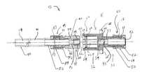
- FIG. 1is an exploded view of the preferred embodiment of the subject optical commutator
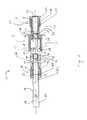
- FIG. 2is a cross-sectional view of the optical commutator of FIG. 1 taken along line 2 - 2 ;
- FIG. 3is a cross-sectional view of the first connector portion of the commutator shown in FIG. 1 taken along line 3 - 3 ;
- FIG. 4is a cross-sectional view of the second connector portion of the commutator shown in FIG. 1 taken along line 4 - 4 ;
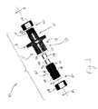
- FIG. 5is a side view of the bushings.
- the subject rotatable fiber coupler or optical commutator 10is provided to couple a pair of associated optical fiber ends 12 and 14 in a rotatable manner.
- a first connector body member 16has a generally cylindrical shape and is preferably radially symmetric about an axis 17 and hollow.
- First connector 16has a threaded end 18 , and a second end 20 which includes a plurality of springy fingers 22 extending axially therefrom in a direction opposite from the threaded end.
- the fingerseach have an extension or protrusion 24 directed radially inward.
- first connector 16defines a first portion 30 into which the first fiber end is selectively inserted, and a second portion 32 adopted to relatively receive a second connector 40 in a manner to be described below.
- the second connector body member 40has a generally cylindrical shape and is also preferably hollow and radially symmetric about an axis 42 .
- Second connector 40includes a threaded end 44 and a radially symmetric circumferential groove 46 .
- Second connector 40is sized to fit inside the fingers 22 of first connector 16 so that a circumferential groove 46 aligns with finger protrusions 24 whereby the first connector 16 and the second connector 40 are detachably coupled, being held together by spring force pressing the finger extensions or protrusions 24 retained in groove 46 .
- the detachable couplingessentially coaxially aligns the symmetry axes 17 and 42 of the first and second connectors 16 , 40 but permits unfettered relative rotational movement of connectors 16 , 40 about the coincident axes 17 , 42 .
- the preferred springy finger-and-groove configurationis illustrated herein for holding the connectors in the coupled relative orientation, many other rotatable interconnects are also contemplated such as replacing the springy fingers 22 with a continuous opening having radially inwardly protruding semi-flexible elements, and other suitable variations or equivalent constructions.
- the first fiber end 12is rigidly attached to the first connector 16 and the second fiber end 14 is rigidly attached to the second connector 40 .
- the pair of fiber endsare coaxially oriented and located in precise close proximity when the first and second connectors are brought together and coupled.
- the relative rotational freedom of connectors 16 , 40provides equivalent relative rotational freedom of the fiber ends 12 , 14 in accordance with the desired mechanical operation of the subject optical commutator 10 .
- the connectors 16 , 40are selectively mechanically coupled by cooperative interaction between the resilient springy fingers 22 of first connector 16 and the groove 46 of second connector 40 as described previously. In that way, the fiber ends are selectively optically coupled by the subject optical commutator 10 .
- first fiber end 12 with first connector 16is now described with reference to FIGS. 2 and 3.
- a first sleeve 50is inserted into an opening 52 at the threaded end 18 of first connector 16 .
- First sleeve 50does not completely insert, but rather extends slightly beyond the threaded end 18 of first connector 16 when maximally inserted.
- a first bushing 54is tightly inserted into an opening 56 accessed through second end 20 of first connector 16 and is held in place preferably by friction.
- bushing 54has an inner opening 100 defining an inside diameter that is preferably essentially the same as the inside diameter of a portion 57 of first connector 16 formed between sleeve opening 52 and bushing opening 56 .
- bushing 54also has an inner lip 110 on one end.
- the fiber jacket 51 and a portion of the optical fiber cladding(not shown) is stripped off a portion 53 of first fiber end 12 .
- the strippingpreferably removes a portion of the fiber cladding because closer tolerances are realized when the cladding is removed compared with jacket removal.
- the outer diameter of the stripped section 53 of first fiber end 12preferably matches the inner diameter of bushing 54 , or equivalently matches the inner diameter of portion 57 of first connector 16 , so that as first fiber end 12 is slidably inserted into the first connector assembly the stripped portion 53 of first fiber end 12 fits closely within bushing 54 and portion 57 of first connector 16 to obtain precise coaxial alignment of first fiber end 12 relative to first connector axis 17 , and also to prevent torsional motion of first fiber end 12 .
- First fiber end 12preferably presses against inner lip 110 of bushing 54 to precisely define the axial position of the first fiber end 12 .
- a first compression fitting 60is provided for locking first fiber end 12 in place within first connector 16 .
- First compression fitting 60includes a split ferrule ring 62 which fits onto the first sleeve 50 , and a ferrule nut 64 which accepts split ferrule ring 62 and threads onto threaded first end 18 of first connector 16 .
- ferrule nut 64is tightened, split ferrule ring 62 compresses first sleeve 50 against first fiber end 12 .
- First sleeve 50thereby distributes the compressive force along an extended length of first fiber end 12 .
- other suitable fittingsmay alternatively be employed, such as replacing the split ferrule ring with an insert including a flange which compresses against first sleeve 50 .
- Second sleeve 70is inserted into an opening 72 at the threaded end 44 of second connector 40 .
- Second sleeve 70does not completely insert, but rather extends slightly beyond the threaded end 44 of second connector 40 when maximally inserted.
- a second bushing 74is tightly inserted into an opening 76 at second end 78 of second connector 40 and is preferably held in place by friction.
- Bushing 74has essentially the same conformation as bushing 54 used in conjunction with first connector 16 , and has an inner opening 100 defining an inside diameter preferably essentially the same as the inside diameter of a portion 77 of second connector 40 lying between sleeve opening 72 and bushing opening 76 .
- bushing 74also has an inner lip 110 on one end.
- the fiber jacket 71 and a portion of the optical fiber cladding(not shown) is stripped off a portion 73 of second fiber end 14 .
- the strippingpreferably removes a portion of the fiber cladding because closer tolerances are obtainable for cladding removal compared with jacket removal.
- the outer diameter of the stripped section 73 of second fiber end 14preferably matches the inner diameter of bushing 74 , or equivalently matches the inner diameter of portion 77 of second connector 40 , so that as second fiber end 14 is slidably inserted into the second connector assembly the stripped section 73 of second fiber end 14 fits closely within bushing 74 and portion 77 of second connector 40 to obtain precise coaxial alignment of second fiber end 14 with second connector axis 42 , and also to prevent torsional motion of second fiber end 14 .
- Second fiber end 14preferably presses against inner lip 110 of bushing 74 to precisely define the axial position of second fiber end 14 relative to the connector body 40 .
- a second compression fitting 80locks second fiber end 14 in place within second connector 40 .
- Second compression fitting 80includes an insert 82 with a flange 83 which presses against second sleeve 70 , and a nut 84 which accepts flange 83 of insert 82 and threads onto threaded first end 44 of second connector 40 .
- Nut 84drives insert flange 83 against second sleeve 70 as nut 84 threads onto threaded end 44 of second connector 40 , and second sleeve 70 is compressively collapsed against second fiber end 14 .
- Second sleeve 70thereby distributes the compressive force along second fiber end 14 .
- other suitable fittingsmay alternatively be employed, such as replacing the insert with a split ferrule ring similar to that used for securing first fiber end 12 within first connector 16 .
- the rigid attachment of second fiber end 14 to second connector 40includes a third sleeve 90 positioned over a length of the second fiber jacket 91 and extending over a portion of insert 82 to reduce the possibility of fiber damage due to excessive mechanical bending.
- a similar sleevemay be included for sealing the connection of first fiber end 12 to first connector 16 if the split ferrule ring 62 is replaced by an insert similar to the insert 82 shown for second compression fitting 80 .
- the subject rotatable optical fiber coupler 10is preferably manufactured from a lightweight, sturdy material such as a plastic material.
- a lightweight, sturdy materialsuch as a plastic material.
- bushings 54 , 74are contemplated to be manufactured from other materials as well, including plastic.
- bushing 54may be integrally formed with the first connector 16 and manufactured as a single unitary piece with a sufficiently thin inner lip.
- bushing 74may be integrally formed with the second connector 40 .
- Inner surfaces of bushings 54 , 74are preferably polished to be highly reflective, especially in the vicinity of the extreme fiber tips where the light coupling across the fiber tips 12 , 14 occurs.
- first fiber end 12is connected by optical fiber to a stationary light source (not shown) and first connector 16 is rigidly attached by mounting bracket 26 to a wall, ceiling, or other fixed location (not shown).
- Second connector 40may then be inserted into first connector 16 by simply pressing second end 78 of second connector 40 into the springy fingers 22 of first connector 16 until the finger extensions 24 engage with groove 46 of the second connector 40 .
- fingers 22are sufficiently stiff to hold second connector 40 in a fixed position in the absence of manual manipulation.
- second connector 40may be rotated about axis 42 without any angular limitations.
- fiber ends 12 , 14remain in precise coaxial alignment defined by the engagement between the connector bodies 16 , 40 , and in close axial proximity defined essentially by the thicknesses of inner lips 110 of bushings 54 , 74 .
- inner lip 110 thicknessesare approximately 15 thousandths of an inch for each lip 110 .
- a thicker inner lip 110typically improves manufacturability but reduces light coupling efficiency due to a correspondingly larger gap.
- second connector 40 and its associated armmay be removed by applying a moderate manual force in opposite axial directions to the first and second connectors 16 , 40 respectively.
- One major advantage of the present inventionis that it facilitates a modular lighting system wherein multiple detachable lighting fixtures are available for different applications, each including a fiber coupler terminating in first connector 40 . Additionally, a single light source may include several fiber connections each terminating in a first connector 16 , and possibly each terminating in a different area of a room or even in different rooms. Any of the detachable lighting fixtures of the modular lighting system may then be attached to any of the several fiber connections of the light source.
- the detachable rotatable optical commutatorfinds application in laser surgery systems, fiber optical communication systems, and other applications where a versatile and detachable fiber coupling may be desirable.
Landscapes
- Physics & Mathematics (AREA)
- General Physics & Mathematics (AREA)
- Optics & Photonics (AREA)
- Mechanical Coupling Of Light Guides (AREA)
Abstract
Description
- This application claims the benefit of Application No. 60/275,058 filed Mar. 12, 2001.[0001]
- The present invention relates to the art of illumination devices useful in general lighting applications and, more particularly, relates to an optical commutator useful in specialized fiber optic lighting applications such as, for example, lighting applications which require convenient, efficient, high intensity, small spot size lighting. However, the invention is applicable in any situation where flexible light piping is required, and the incorporated light source may include incandescent, fluorescent, laser, or other light sources.[0002]
- Electrical lamp apparatus have been in existence at least since the invention of the incandescent light bulb. Many modern electric lamps still utilize incandescent sources essentially similar to the original design but incorporating improved filament materials, better electrical current and voltage control, improved vacuum quality, and other improvements. Other modern lamp apparatus employ fluorescent light sources which typically exhibit higher efficiency and longer service life versus incandescent sources. Specialty lamps are also available which use novel sources such as gas discharge tubes using mercury, sodium, or other gas vapors, xenon arc lamps, gas lasers, semiconductor lasers and light emitting diodes (LED's), and other optical sources.[0003]
- Beyond the light source, the properties of a lamp system are dictated primarily by the optical path design. In the simplest case, there may be no defined optical path, for example, a ceiling fluorescent tube with no associated optical components other than light diffusers, filters, or the like. More commonly, the omni directional light output is conditioned through the use of parabolic reflectors, flat reflectors, lenses or other refractive elements, diffusers such as lamp shades, spectral filters, apertures, and the like.[0004]
- In the case of a fixed, immobile lamp, a great deal of engineering freedom exists in the design of the optical path. Optical path design options are significantly restricted, however, in cases where the point of light emission must be mounted on a flexible arm so that the direction or physical location of the light emission is adjustable. An example is the desktop lamp, which in the conventional commercial design includes a flexible arm such as a “gooseneck” flexible arm, multiple-segment multiple-hinged arm, or the like, and a light emitting head which includes an incandescent or fluorescent light source and associated reflectors or other optical components. Other lamp types which may require flexible mounting and therefore typically incorporate the above-described basic design include surgical operating room lamps and lamps for precision mechanical operations such as semiconductor wire bonding, jewelry work, and other fine mechanical tasks.[0005]
- The requirements for the light emitting head typically include: high brightness, low temperature operation, small spatial size, and low weight. High intensity is required due to the nature of many applications, such as reading and precision jewelry work. Preferably, the lighthead temperature is close to ambient temperature, especially for applications such as desk lighting where the lighthead will be close to a user's face and hands. A small lighthead size is preferable for flexibility in positioning. Low weight is preferable to reduce the mass and cost of the weight-bearing flexible arm.[0006]
- Conventional lamp designs employing a flexible arm and attached head containing at least the light source require undesirable engineering design compromises between light intensity, thermal temperature, size, and weight. The desired high intensity sources are usually larger and heavier than lower intensity sources. High intensity sources also tend to generate a large amount of heat. The heating problem is especially acute for incandescent sources because these sources tend to be rather inefficient. Replacement of incandescent bulbs by fluorescent tubes may greatly reduce the operating temperature, typically with an accompanying decrease in light intensity which may however be acceptable for certain applications. Improved optics which provide better coupling of the generated light to the area requiring illumination are also beneficial, but the optics may also increase head size and weight.[0007]
- A different solution to the need for a flexible lighting source has become available with the advent of fiber optics. Using fiber optical transmission permits decoupling of the light source from the point of light emission. A design incorporating fiber optics may include a large, hot, heavy, high intensity light source positioned remotely from a light emitting head. The head is movably located at the point of light emission and is connected to the light source by a fiber optical link. The head need only contain those optical components such as reflectors, lenses, and the like which are necessary to shape the fiber optical output appropriately for the application. Certain optical components, such as spectral filters, may be placed near the light source remote from the head. An additional advantage of incorporating fiber optical transmission is that a single light source may provide optical power for a number of flexibly positioned heads. Such a system could be valuable, for example, in a hospital operating room where the surgical area may preferably be illuminated from two or more different angles to reduce shadowing.[0008]
- In spite of the benefits potentially available through the incorporation of fiber optics into flexibly positioned lighting systems, practical difficulties have resulted in limited use of fiber optics in such systems. A critical issue is light transmission efficiency at fiber coupling points. Efficient coupling between adjacent fibers requires similar or preferably identical fiber core sizes, smooth fiber end cleaves preferably including anti-reflection coatings, and extremely precise axial and angular alignment of the two fiber tips. For a flexible lamp, the close axial and angular alignment must be maintained as the lamp arm is moved and rotated about the mechanical joints where the fiber coupling typically is employed.[0009]
- The prior art teaches using standard threaded and snap connectors for connecting fiber optical segments. However, there is a need for a convenient and reliable mechanical configuration for providing a fully rotatable fiber coupling where one fiber end may be rotated freely with respect to the other fiber end while maintaining efficient optical coupling. Such an optical coupling may conveniently be called an “optical commutator” in close analogy to the electrical commutator typically employed in connection of rotor windings in electric motors and generators. An optical commutator having a high light transmission efficiency is a highly desired and critical element for lamp designs in which an arm bearing a fiber-coupled light emitting head is to be freely rotatable about a joint.[0010]
- It is further desired to provide an optical commutator that finds application well beyond lighting systems. Fiber optics are used increasingly in communications and in various medical applications, among others. The optical commutator is applicable to desired areas identified above as well as others where rotatable coupling of fiber segments may be desirable.[0011]
- In accordance with one aspect of the present invention, a rotatable optical fiber coupler for coupling a first fiber with a second fiber is provided. A first hollow radially symmetric connector has a threaded first end and a second end having a plurality of resilient springy fingers extending therefrom in the axial direction, the fingers having extensions directed radially inward. A second hollow radially symmetric connector has a threaded first end, the second connector also having a circumferential groove on the outer surface. The second connector detachably attaches coaxially to the first connector by spring force pressing the finger extensions of the first connector into the groove of the second connector, whereby the second connector may rotate about the coaxial axis relative to the first connector.[0012]
- A first sleeve is positioned over a length of the first optical fiber and is received into an opening in the threaded end of the first connector, the first sleeve pressing against the first connector and against the first fiber. A second sleeve is positioned over a length of the second optical fiber and is received into the second connector, the second sleeve pressing against the second connector and against the second fiber.[0013]
- A first bushing securely fits into a space in the second end of the first connector and receives an end of the first fiber after the fiber jacket and a portion of the fiber cladding has been stripped from said end. The first bushing has an inner lip against which the first fiber end presses. A second bushing securely fits into a space in a second end of the second connector and receives an end of the second optical fiber after the fiber jacket and a portion of the fiber cladding has been stripped from said end. The second bushing has an inner lip against which the second fiber end presses.[0014]
- A first compression fitting is provided to secure the first fiber end to the first connector. The first compression fitting includes a split ferrule ring which fits onto the first sleeve, and a ferrule nut which accepts the split ferrule ring and threads onto the threaded first end of the first connector, whereby the first sleeve distributively compresses against the first fiber end and secures the first fiber end in the first connector.[0015]
- A second compression fitting is provided to secure the second fiber end to the second connector. The second compression fitting includes an insert with a flange which presses against the second sleeve. A nut accepts the flange of the insert and threads onto the threaded first end of the second connector, whereby the flange compresses against the second sleeve and compressively secures the second fiber end in the second connector[0016]
- In accordance with another aspect of the present invention, an optical commutator for coupling a second fiber end to a first fiber end in a detachable rotatable manner is disclosed. A second connecting piece is essentially tubular in shape. The second fiber end is inserted completely through the second connecting piece and held rigidly therein such that the second fiber end is set back a preselected distance. A first connecting piece is essentially tubular in shape and essentially divided along the axial direction into a first portion into which the first fiber end is inserted and held rigidly, and a second portion into which a portion of the second connecting piece is coaxially detachably inserted and rotatably attached therein. The first portion and the second portion are apportioned such that the first fiber end is coaxial with and in close proximity to the second fiber end whereby light coupling across the fiber ends is obtained.[0017]
- Preferably, the detachable attachment of the second connecting piece to the first connecting piece second portion includes an axially symmetric groove on an outer surface of the second connecting piece, and an axially symmetric protrusion on an inner surface of the second portion of the first connecting piece which essentially mates with the axially symmetric groove of the second connecting piece.[0018]
- One advantage of the present invention is that a fully rotatable light-emitting head may remain cool during operation independent of the temperature of the light source.[0019]
- Another advantage of the present invention is that it decouples the light-emitting head from the light source of a flexibly positioned lighting source.[0020]
- Another advantage of the present invention is that it permits full rotation of an arm bearing a light-emitting head about any angle, even including angles beyond 0°-360°, i.e. multiple turn rotation.[0021]
- Another advantage of the present invention is that it provides a rotatable fiber coupling which is easily detachable.[0022]
- Another advantage of the present invention is that it facilitates a modular lighting system wherein multiple detachable lighting fixtures are available for different applications.[0023]
- Yet another advantage of the present invention is that it efficiently couples light via fiber optical connection from a light source through a fully, continuously rotatable joint in a lamp arm.[0024]
- Still further advantages and benefits of the present invention will become apparent to those of ordinary skill in the art upon reading and understanding the following detailed description.[0025]
- The invention may take form in various components and arrangements of components, and in various steps and arrangements of steps. The drawings are only for the purposes of illustrating preferred embodiments and are not to be construed as limiting the invention.[0026]
- FIG. 1 is an exploded view of the preferred embodiment of the subject optical commutator;[0027]
- FIG. 2 is a cross-sectional view of the optical commutator of FIG. 1 taken along line[0028]2-2;
- FIG. 3 is a cross-sectional view of the first connector portion of the commutator shown in FIG. 1 taken along line[0029]3-3;
- FIG. 4 is a cross-sectional view of the second connector portion of the commutator shown in FIG. 1 taken along line[0030]4-4; and
- FIG. 5 is a side view of the bushings.[0031]
- With reference to FIGS.[0032]1-5, a preferred embodiment of the invention will be described. The subject rotatable fiber coupler or
optical commutator 10 is provided to couple a pair of associated optical fiber ends12 and14 in a rotatable manner. A firstconnector body member 16 has a generally cylindrical shape and is preferably radially symmetric about an axis17 and hollow.First connector 16 has a threadedend 18, and asecond end 20 which includes a plurality ofspringy fingers 22 extending axially therefrom in a direction opposite from the threaded end. The fingers each have an extension orprotrusion 24 directed radially inward. Preferably, a mountingbracket 26 is integrally formed into the firstconnector body member 16 whereby the first connector may be secured to an associated fixture by mountingholes 28 or the like. It will be recognized thatfirst connector 16 defines afirst portion 30 into which the first fiber end is selectively inserted, and asecond portion 32 adopted to relatively receive asecond connector 40 in a manner to be described below. - The second[0033]
connector body member 40 has a generally cylindrical shape and is also preferably hollow and radially symmetric about anaxis 42.Second connector 40 includes a threadedend 44 and a radially symmetriccircumferential groove 46.Second connector 40 is sized to fit inside thefingers 22 offirst connector 16 so that acircumferential groove 46 aligns withfinger protrusions 24 whereby thefirst connector 16 and thesecond connector 40 are detachably coupled, being held together by spring force pressing the finger extensions orprotrusions 24 retained ingroove 46. The detachable coupling essentially coaxially aligns the symmetry axes17 and42 of the first andsecond connectors connectors coincident axes 17,42. It will be recognized that although the preferred springy finger-and-groove configuration is illustrated herein for holding the connectors in the coupled relative orientation, many other rotatable interconnects are also contemplated such as replacing thespringy fingers 22 with a continuous opening having radially inwardly protruding semi-flexible elements, and other suitable variations or equivalent constructions. - Preferably, the[0034]
first fiber end 12 is rigidly attached to thefirst connector 16 and thesecond fiber end 14 is rigidly attached to thesecond connector 40. The pair of fiber ends are coaxially oriented and located in precise close proximity when the first and second connectors are brought together and coupled. As a consequence, the relative rotational freedom ofconnectors optical commutator 10. Theconnectors springy fingers 22 offirst connector 16 and thegroove 46 ofsecond connector 40 as described previously. In that way, the fiber ends are selectively optically coupled by the subjectoptical commutator 10. - The rigid attachment of[0035]
first fiber end 12 withfirst connector 16 is now described with reference to FIGS. 2 and 3. Afirst sleeve 50 is inserted into anopening 52 at the threadedend 18 offirst connector 16.First sleeve 50 does not completely insert, but rather extends slightly beyond the threadedend 18 offirst connector 16 when maximally inserted. - A[0036]
first bushing 54 is tightly inserted into anopening 56 accessed throughsecond end 20 offirst connector 16 and is held in place preferably by friction. As seen in FIG. 5, bushing54 has aninner opening 100 defining an inside diameter that is preferably essentially the same as the inside diameter of aportion 57 offirst connector 16 formed betweensleeve opening 52 andbushing opening 56. As shown in FIG. 5, bushing54 also has aninner lip 110 on one end. - The fiber jacket[0037]51 and a portion of the optical fiber cladding (not shown) is stripped off a
portion 53 offirst fiber end 12. The stripping preferably removes a portion of the fiber cladding because closer tolerances are realized when the cladding is removed compared with jacket removal. The outer diameter of the strippedsection 53 offirst fiber end 12 preferably matches the inner diameter ofbushing 54, or equivalently matches the inner diameter ofportion 57 offirst connector 16, so that asfirst fiber end 12 is slidably inserted into the first connector assembly the strippedportion 53 offirst fiber end 12 fits closely withinbushing 54 andportion 57 offirst connector 16 to obtain precise coaxial alignment offirst fiber end 12 relative to first connector axis17, and also to prevent torsional motion offirst fiber end 12.First fiber end 12 preferably presses againstinner lip 110 ofbushing 54 to precisely define the axial position of thefirst fiber end 12. - A first compression fitting[0038]60 is provided for locking
first fiber end 12 in place withinfirst connector 16. First compression fitting60 includes asplit ferrule ring 62 which fits onto thefirst sleeve 50, and aferrule nut 64 which accepts splitferrule ring 62 and threads onto threadedfirst end 18 offirst connector 16. Asferrule nut 64 is tightened, splitferrule ring 62 compressesfirst sleeve 50 againstfirst fiber end 12.First sleeve 50 thereby distributes the compressive force along an extended length offirst fiber end 12. Of course, other suitable fittings may alternatively be employed, such as replacing the split ferrule ring with an insert including a flange which compresses againstfirst sleeve 50. - Turning now to the[0039]
second connector 40 shown in FIGS. 2 and 4, a second sleeve70 is inserted into anopening 72 at the threadedend 44 ofsecond connector 40. Second sleeve70 does not completely insert, but rather extends slightly beyond the threadedend 44 ofsecond connector 40 when maximally inserted. - A[0040]
second bushing 74 is tightly inserted into anopening 76 atsecond end 78 ofsecond connector 40 and is preferably held in place by friction.Bushing 74 has essentially the same conformation asbushing 54 used in conjunction withfirst connector 16, and has aninner opening 100 defining an inside diameter preferably essentially the same as the inside diameter of aportion 77 ofsecond connector 40 lying betweensleeve opening 72 andbushing opening 76. As shown in FIG. 5, bushing74 also has aninner lip 110 on one end. - The[0041]
fiber jacket 71 and a portion of the optical fiber cladding (not shown) is stripped off aportion 73 ofsecond fiber end 14. The stripping preferably removes a portion of the fiber cladding because closer tolerances are obtainable for cladding removal compared with jacket removal. The outer diameter of the strippedsection 73 ofsecond fiber end 14 preferably matches the inner diameter ofbushing 74, or equivalently matches the inner diameter ofportion 77 ofsecond connector 40, so that assecond fiber end 14 is slidably inserted into the second connector assembly the strippedsection 73 ofsecond fiber end 14 fits closely withinbushing 74 andportion 77 ofsecond connector 40 to obtain precise coaxial alignment ofsecond fiber end 14 withsecond connector axis 42, and also to prevent torsional motion ofsecond fiber end 14.Second fiber end 14 preferably presses againstinner lip 110 ofbushing 74 to precisely define the axial position ofsecond fiber end 14 relative to theconnector body 40. - A second compression fitting[0042]80 locks
second fiber end 14 in place withinsecond connector 40. Second compression fitting80 includes aninsert 82 with aflange 83 which presses against second sleeve70, and anut 84 which acceptsflange 83 ofinsert 82 and threads onto threadedfirst end 44 ofsecond connector 40.Nut 84 drives insertflange 83 against second sleeve70 asnut 84 threads onto threadedend 44 ofsecond connector 40, and second sleeve70 is compressively collapsed againstsecond fiber end 14. Second sleeve70 thereby distributes the compressive force alongsecond fiber end 14. Of course, other suitable fittings may alternatively be employed, such as replacing the insert with a split ferrule ring similar to that used for securingfirst fiber end 12 withinfirst connector 16. - Preferably, the rigid attachment of[0043]
second fiber end 14 tosecond connector 40 includes athird sleeve 90 positioned over a length of thesecond fiber jacket 91 and extending over a portion ofinsert 82 to reduce the possibility of fiber damage due to excessive mechanical bending. Although not illustrated here, a similar sleeve may be included for sealing the connection offirst fiber end 12 tofirst connector 16 if thesplit ferrule ring 62 is replaced by an insert similar to theinsert 82 shown for second compression fitting80. - The subject rotatable[0044]
optical fiber coupler 10 is preferably manufactured from a lightweight, sturdy material such as a plastic material. In order to provide a precise gap between the fiber ends required for good light coupling across the gap, it was found preferable to use separately manufactured bushings as described above, and these bushings are preferably made from aluminum. However,bushings first connector 16 and manufactured as a single unitary piece with a sufficiently thin inner lip. Similarly, bushing74 may be integrally formed with thesecond connector 40. Inner surfaces ofbushings fiber tips - Having described the preferred structure of the subject[0045]
optical commutator 10, the operation of the commutator is now described. For exemplary purposes only, it will be assumed thatfirst fiber end 12 is connected by optical fiber to a stationary light source (not shown) andfirst connector 16 is rigidly attached by mountingbracket 26 to a wall, ceiling, or other fixed location (not shown).Second connector 40 may then be inserted intofirst connector 16 by simply pressingsecond end 78 ofsecond connector 40 into thespringy fingers 22 offirst connector 16 until thefinger extensions 24 engage withgroove 46 of thesecond connector 40. Preferably,fingers 22 are sufficiently stiff to holdsecond connector 40 in a fixed position in the absence of manual manipulation. By applying manual force,second connector 40 may be rotated aboutaxis 42 without any angular limitations. For all relative rotational angles betweenfirst connector 16 andsecond connector 40, fiber ends12,14 remain in precise coaxial alignment defined by the engagement between theconnector bodies inner lips 110 ofbushings inner lip 110 thicknesses are approximately 15 thousandths of an inch for eachlip 110. A thickerinner lip 110 typically improves manufacturability but reduces light coupling efficiency due to a correspondingly larger gap. If desired,second connector 40 and its associated arm may be removed by applying a moderate manual force in opposite axial directions to the first andsecond connectors - One major advantage of the present invention is that it facilitates a modular lighting system wherein multiple detachable lighting fixtures are available for different applications, each including a fiber coupler terminating in[0046]
first connector 40. Additionally, a single light source may include several fiber connections each terminating in afirst connector 16, and possibly each terminating in a different area of a room or even in different rooms. Any of the detachable lighting fixtures of the modular lighting system may then be attached to any of the several fiber connections of the light source. - Other applications, including applications outside of lighting, are contemplated for the subject commutator. The detachable rotatable optical commutator finds application in laser surgery systems, fiber optical communication systems, and other applications where a versatile and detachable fiber coupling may be desirable.[0047]
- The invention has been described with reference to the preferred embodiment. Obviously, modifications and alterations will occur to others upon reading and understanding the preceding detailed description. It is intended that the invention be construed as including all such modifications and alterations insofar as they come within the scope of the appended claims or the equivalents thereof.[0048]
Claims (15)
1. A rotatable optical fiber coupler for coupling a first fiber with a second fiber, comprising:
a first essentially radially symmetric connector which is essentially hollow and has a threaded first end and a second end having a plurality of springy fingers extending therefrom essentially in the axial direction, the fingers having extensions directed essentially radially inward;
a second essentially radially symmetric connector which is essentially hollow and has a threaded first end, the second connector also having a circumferential groove on the outer surface, the second connector detachably attached coaxially to the first connector by spring force pressing the finger extensions of the first connector into the groove of the second connector, whereby the second connector may rotate about the coaxial axis relative to the first connector;
a first sleeve positioned over a length of the first optical fiber and received into an opening inside the threaded first end of the first connector;
a second sleeve positioned over a length of the second optical fiber and received into an opening inside the threaded first end of the second connector;
a first bushing which securely fits into a space in the second end of the first connector and which receives an end of the first fiber after the fiber jacket and a portion of the fiber cladding is stripped from said end, the first bushing having an inner lip against which the first fiber end presses;
a second bushing which securely fits into a space in a second end of the second connector and which receives an end of the second fiber after the fiber jacket and a portion of the fiber cladding is stripped from said end, the second bushing having an inner lip against which the second fiber end presses;
a first compression fitting including,
a split ferrule ring which fits onto the first sleeve and is compressively held thereto, and
a ferrule nut which accepts the split ferrule ring and threads onto the threaded first end of the first connector, whereby the first connector distributively compresses against the first sleeve and secures the first fiber end in the first connector; and
a second compression fitting including,
an insert having a flange which presses against the second sleeve, and
a nut which accepts the flange of the insert and threads onto the threaded first end of the second connector, whereby the flange compresses against the second sleeve and secures the second fiber end in the second connector.
2. The rotatable optical fiber coupler as set forth inclaim 1 , further comprising:
a third sleeve positioned over a length of the second optical fiber and extending over a portion of the insert of the second compression fitting.
3. The rotatable optical fiber coupler as set forth inclaim 1 , wherein the first connector further comprises:
a mounting bracket integrally formed into the first connector whereby the first connector may be secured to an associated fixture.
4. The rotatable optical fiber coupler as set forth inclaim 1 , wherein:
the first bushing is manufactured from metal;
the second bushing is manufactured from metal; and
the remaining components are manufactured from plastic.
5. The rotatable optical fiber coupler as set forth inclaim 1 , wherein:
the first bushing is integrally molded into the first connector;
the second bushing is integrally molded into the second connector; and
the first and second connectors are manufactured from plastic.
6. The rotatable optical fiber coupler as set forth inclaim 1 , wherein:
the detaching of the second connector from the first connector is obtained by applying a moderate manual force in opposite axial directions to the first and second connectors, respectively.
7. The rotatable optical fiber coupler as set forth inclaim 1 , wherein:
the first connector includes a portion between the first bushing and the first sleeve wherein the inner diameter is essentially similar to the inner diameter of the first bushing; and
the second connector includes a portion between the second bushing and the second sleeve wherein the inner diameter is essentially similar to the inner diameter of the second bushing.
8. An optical commutator for coupling a second fiber end to a first fiber end in a detachable rotatable manner, comprising:
a second connecting piece which is essentially tubular in shape and into which the second fiber end is inserted completely through and held rigidly therein such that the second fiber end is set back a preselected distance from an end of the second connecting piece; and
a first connecting piece which is essentially tubular in shape and essentially divided along the axial direction into,
a first portion into which the first fiber end is inserted and held rigidly, and
a second portion into which a portion of the second connecting piece is coaxially detachably inserted and rotatably attached therein,
the first portion and the second portion being apportioned such that the first fiber end is coaxial with and in close proximity to the second fiber end whereby light coupling across the fiber ends is obtained.
9. The optical commutator as set forth inclaim 8 where the detachable attachment of the second connecting piece to the first connecting piece second portion includes:
an axially symmetric groove on an outer surface of the second connecting piece; and
an axially symmetric protrusion on an inner surface of the second portion of the first connecting piece which essentially mates with the axially symmetric groove of the second connecting piece.
10. A fiber coupler for operatively coupling a first fiber with a second fiber, comprising:
a first connector body member adapted to receive an end of said first fiber;
a set of resilient fingers on the first connector body member; and,
a second connector body member adapted to receive an end of said second fiber, the second connector body member defining a circular groove adapted to receive said set of resilient fingers when the first and second connector body members are in an intermated coupled configuration.
11. The fiber coupler according toclaim 10 wherein:
the first connector body member defines a first longitudinal axis; and,
the second connector body member defines a second longitudinal axis substantially coincident with the first longitudinal axis.
12. The fiber coupler according toclaim 11 further including:
a plurality of resilient fingers extending along said first longitudinal axis from said first connector body member, the plurality of resilient fingers having radially inwardly extending extensions adapted to be received in said circular groove on said second connector body member when the first and second connector body members are in said intermated coupled configuration.
13. The fiber coupler according toclaim 10 wherein the first and second connector body members are mutually rotatable while said set of resilient fingers are engaged in said circular groove.
14. The fiber coupler according toclaim 10 wherein at least one of the first and second connector body members includes a connection portion for connecting the fiber coupler to an associated support member.
15. The fiber coupler according toclaim 10 wherein the first and second connector body members are made of plastic.
Priority Applications (1)
| Application Number | Priority Date | Filing Date | Title |
|---|---|---|---|
| US10/096,395US6758599B2 (en) | 2001-03-12 | 2002-03-12 | Optical commutator |
Applications Claiming Priority (2)
| Application Number | Priority Date | Filing Date | Title |
|---|---|---|---|
| US27505801P | 2001-03-12 | 2001-03-12 | |
| US10/096,395US6758599B2 (en) | 2001-03-12 | 2002-03-12 | Optical commutator |
Publications (2)
| Publication Number | Publication Date |
|---|---|
| US20020126959A1true US20020126959A1 (en) | 2002-09-12 |
| US6758599B2 US6758599B2 (en) | 2004-07-06 |
Family
ID=26791665
Family Applications (1)
| Application Number | Title | Priority Date | Filing Date |
|---|---|---|---|
| US10/096,395Expired - LifetimeUS6758599B2 (en) | 2001-03-12 | 2002-03-12 | Optical commutator |
Country Status (1)
| Country | Link |
|---|---|
| US (1) | US6758599B2 (en) |
Cited By (5)
| Publication number | Priority date | Publication date | Assignee | Title |
|---|---|---|---|---|
| US20040028343A1 (en)* | 2002-05-22 | 2004-02-12 | Yonezawa Electric Wire Co., Ltd. | Optical connector |
| RU2231816C1 (en)* | 2003-03-26 | 2004-06-27 | Жувикин Георгий Викторович | Multichannel optoelectronic commutation system |
| US9110255B2 (en)* | 2014-01-15 | 2015-08-18 | Optomedia Technology Incorporation | Optical connector, optical transmission device and assembly method for optical transmission device |
| CN112443541A (en)* | 2019-09-01 | 2021-03-05 | 九江精密测试技术研究所 | High-precision mechanical locking device for rotary table |
| EP4116756A1 (en)* | 2021-07-08 | 2023-01-11 | Schott Ag | Modular articulable impact-proof vision system |
Families Citing this family (7)
| Publication number | Priority date | Publication date | Assignee | Title |
|---|---|---|---|---|
| US20050113814A1 (en)* | 2003-11-24 | 2005-05-26 | Loeb Marvin P. | Apparatus and method for limiting the re-use of fiber optic, laser energy delivery devices |
| DE102006047207B3 (en)* | 2006-10-05 | 2008-07-03 | Fachhochschule Koblenz | Optical rotary distributor for optical fibers |
| RU2402794C1 (en)* | 2009-04-14 | 2010-10-27 | Закрытое акционерное общество "Центр волоконно-оптических систем передачи информации" (ЗАО "Центр ВОСПИ") | Optical cable connector |
| US20100271804A1 (en)* | 2009-04-22 | 2010-10-28 | Levine Jonathan E | Modular lighting device kit |
| US20140003769A1 (en)* | 2012-06-29 | 2014-01-02 | Precision Optics Corporation, Inc. | Quick connect coupler for optical fiber cable |
| US11675135B2 (en)* | 2019-07-10 | 2023-06-13 | Bios Srl | Rotatable connector for an optical fiber |
| US11712319B2 (en) | 2020-03-27 | 2023-08-01 | American Sterilizer Company | 360 degrees plus rotation camera module for surgical light head handle |
Citations (29)
| Publication number | Priority date | Publication date | Assignee | Title |
|---|---|---|---|---|
| US3912918A (en)* | 1974-04-22 | 1975-10-14 | Designs For Vision | Light sources employing universally adjustable ball and socket joints |
| US3963323A (en)* | 1974-12-23 | 1976-06-15 | International Telephone And Telegraph Corporation | Fiber optic connector with protective cable sleeves |
| US4101198A (en)* | 1976-06-21 | 1978-07-18 | Hewlett-Packard Company | Fiber optic connector with split ferrule assembly |
| US4121272A (en)* | 1977-05-02 | 1978-10-17 | General Electric Company | Torsional oscillation alarm system |
| US4127319A (en)* | 1977-06-01 | 1978-11-28 | Amp Incorporated | Termination means for fiber optic bundle |
| US4140365A (en)* | 1976-04-24 | 1979-02-20 | Itt Industries, Inc. | Fiber optic cable connector housing |
| US4190316A (en)* | 1978-02-02 | 1980-02-26 | The Deutsch Company | Lens connector for optical fibers |
| US4225214A (en)* | 1978-09-18 | 1980-09-30 | Trw Inc. | Connector construction |
| US4240695A (en)* | 1979-06-20 | 1980-12-23 | E. I. Du Pont De Nemours And Company | Optical fibers connector |
| US4268115A (en)* | 1979-06-01 | 1981-05-19 | Tetra-Tech, Inc. | Quick-release fiber-optic connector |
| US4279468A (en)* | 1977-05-02 | 1981-07-21 | Plessey Handel Und Investments Ag | Optical fiber connectors |
| US4303300A (en)* | 1979-02-07 | 1981-12-01 | Thomson-Csf | Rotary-joint device providing for an optical waveguide transmission |
| US4309071A (en)* | 1978-10-23 | 1982-01-05 | Souriau & Cie (Sa) | Connector for optical fibers and device for mounting fibers on tips directly usable on connectors |
| US4676588A (en)* | 1983-06-01 | 1987-06-30 | Amp Incorporated | Fiber optic connector |
| US4747656A (en)* | 1985-05-09 | 1988-05-31 | Alps Electric Co., Ltd. | Optical fiber connector with locking mechanism |
| US4755019A (en)* | 1986-08-16 | 1988-07-05 | W. C. Heraeus Gmbh | Optical fiber coupling |
| US4756595A (en)* | 1986-04-21 | 1988-07-12 | Honeywell Inc. | Optical fiber connector for high pressure environments |
| US4799759A (en)* | 1986-06-26 | 1989-01-24 | G & H Technology, Inc. | Fiber optic connector |
| US4870952A (en)* | 1983-10-28 | 1989-10-03 | Miquel Martinez | Fiber optic illuminator for use in surgery |
| US4872736A (en)* | 1988-04-19 | 1989-10-10 | American Telephone And Telegraph Company, At&T Bell Laboratories | Connector assembly having a latching mechanism |
| US4909589A (en)* | 1988-12-11 | 1990-03-20 | Morris Robert K | Rotatable photonic coupling |
| US5039193A (en)* | 1990-04-03 | 1991-08-13 | Focal Technologies Incorporated | Fibre optic single mode rotary joint |
| US5125056A (en)* | 1986-05-14 | 1992-06-23 | Mcdonnell Douglas Corporation | Fiber optic connector assembly |
| US5337386A (en)* | 1992-12-22 | 1994-08-09 | Hughes Aircraft Company | Single channel snap-lock fiber optic connector |
| US5633963A (en)* | 1995-12-12 | 1997-05-27 | Raytheon Company | Optical rotary joint for single and multimode fibers |
| US5872879A (en)* | 1996-11-25 | 1999-02-16 | Boston Scientific Corporation | Rotatable connecting optical fibers |
| US6053639A (en)* | 1998-07-01 | 2000-04-25 | Chen; Chung-Fang | Optic fiber inner tube connector |
| US6152608A (en)* | 1998-04-10 | 2000-11-28 | Packard Hughes Interconnect Company | Snap lock connector for optical fiber systems |
| US6443626B1 (en)* | 1999-04-09 | 2002-09-03 | Itt Manufacturing Enterprises, Inc. | Optical fibre connector having bayonet coupling |
Family Cites Families (2)
| Publication number | Priority date | Publication date | Assignee | Title |
|---|---|---|---|---|
| DE2516858C2 (en) | 1975-04-17 | 1983-01-20 | Siemens AG, 1000 Berlin und 8000 München | Detachable plug connection for optical fibers |
| US4124272A (en) | 1976-12-14 | 1978-11-07 | Westinghouse Electric Corp. | Rotary fiber optic waveguide coupling |
- 2002
- 2002-03-12USUS10/096,395patent/US6758599B2/ennot_activeExpired - Lifetime
Patent Citations (29)
| Publication number | Priority date | Publication date | Assignee | Title |
|---|---|---|---|---|
| US3912918A (en)* | 1974-04-22 | 1975-10-14 | Designs For Vision | Light sources employing universally adjustable ball and socket joints |
| US3963323A (en)* | 1974-12-23 | 1976-06-15 | International Telephone And Telegraph Corporation | Fiber optic connector with protective cable sleeves |
| US4140365A (en)* | 1976-04-24 | 1979-02-20 | Itt Industries, Inc. | Fiber optic cable connector housing |
| US4101198A (en)* | 1976-06-21 | 1978-07-18 | Hewlett-Packard Company | Fiber optic connector with split ferrule assembly |
| US4279468A (en)* | 1977-05-02 | 1981-07-21 | Plessey Handel Und Investments Ag | Optical fiber connectors |
| US4121272A (en)* | 1977-05-02 | 1978-10-17 | General Electric Company | Torsional oscillation alarm system |
| US4127319A (en)* | 1977-06-01 | 1978-11-28 | Amp Incorporated | Termination means for fiber optic bundle |
| US4190316A (en)* | 1978-02-02 | 1980-02-26 | The Deutsch Company | Lens connector for optical fibers |
| US4225214A (en)* | 1978-09-18 | 1980-09-30 | Trw Inc. | Connector construction |
| US4309071A (en)* | 1978-10-23 | 1982-01-05 | Souriau & Cie (Sa) | Connector for optical fibers and device for mounting fibers on tips directly usable on connectors |
| US4303300A (en)* | 1979-02-07 | 1981-12-01 | Thomson-Csf | Rotary-joint device providing for an optical waveguide transmission |
| US4268115A (en)* | 1979-06-01 | 1981-05-19 | Tetra-Tech, Inc. | Quick-release fiber-optic connector |
| US4240695A (en)* | 1979-06-20 | 1980-12-23 | E. I. Du Pont De Nemours And Company | Optical fibers connector |
| US4676588A (en)* | 1983-06-01 | 1987-06-30 | Amp Incorporated | Fiber optic connector |
| US4870952A (en)* | 1983-10-28 | 1989-10-03 | Miquel Martinez | Fiber optic illuminator for use in surgery |
| US4747656A (en)* | 1985-05-09 | 1988-05-31 | Alps Electric Co., Ltd. | Optical fiber connector with locking mechanism |
| US4756595A (en)* | 1986-04-21 | 1988-07-12 | Honeywell Inc. | Optical fiber connector for high pressure environments |
| US5125056A (en)* | 1986-05-14 | 1992-06-23 | Mcdonnell Douglas Corporation | Fiber optic connector assembly |
| US4799759A (en)* | 1986-06-26 | 1989-01-24 | G & H Technology, Inc. | Fiber optic connector |
| US4755019A (en)* | 1986-08-16 | 1988-07-05 | W. C. Heraeus Gmbh | Optical fiber coupling |
| US4872736A (en)* | 1988-04-19 | 1989-10-10 | American Telephone And Telegraph Company, At&T Bell Laboratories | Connector assembly having a latching mechanism |
| US4909589A (en)* | 1988-12-11 | 1990-03-20 | Morris Robert K | Rotatable photonic coupling |
| US5039193A (en)* | 1990-04-03 | 1991-08-13 | Focal Technologies Incorporated | Fibre optic single mode rotary joint |
| US5337386A (en)* | 1992-12-22 | 1994-08-09 | Hughes Aircraft Company | Single channel snap-lock fiber optic connector |
| US5633963A (en)* | 1995-12-12 | 1997-05-27 | Raytheon Company | Optical rotary joint for single and multimode fibers |
| US5872879A (en)* | 1996-11-25 | 1999-02-16 | Boston Scientific Corporation | Rotatable connecting optical fibers |
| US6152608A (en)* | 1998-04-10 | 2000-11-28 | Packard Hughes Interconnect Company | Snap lock connector for optical fiber systems |
| US6053639A (en)* | 1998-07-01 | 2000-04-25 | Chen; Chung-Fang | Optic fiber inner tube connector |
| US6443626B1 (en)* | 1999-04-09 | 2002-09-03 | Itt Manufacturing Enterprises, Inc. | Optical fibre connector having bayonet coupling |
Cited By (6)
| Publication number | Priority date | Publication date | Assignee | Title |
|---|---|---|---|---|
| US20040028343A1 (en)* | 2002-05-22 | 2004-02-12 | Yonezawa Electric Wire Co., Ltd. | Optical connector |
| US6945703B2 (en)* | 2002-05-22 | 2005-09-20 | Yonezawa Electric Wire Co., Ltd. | Optical connector |
| RU2231816C1 (en)* | 2003-03-26 | 2004-06-27 | Жувикин Георгий Викторович | Multichannel optoelectronic commutation system |
| US9110255B2 (en)* | 2014-01-15 | 2015-08-18 | Optomedia Technology Incorporation | Optical connector, optical transmission device and assembly method for optical transmission device |
| CN112443541A (en)* | 2019-09-01 | 2021-03-05 | 九江精密测试技术研究所 | High-precision mechanical locking device for rotary table |
| EP4116756A1 (en)* | 2021-07-08 | 2023-01-11 | Schott Ag | Modular articulable impact-proof vision system |
Also Published As
| Publication number | Publication date |
|---|---|
| US6758599B2 (en) | 2004-07-06 |
Similar Documents
| Publication | Publication Date | Title |
|---|---|---|
| US6758599B2 (en) | Optical commutator | |
| US6234640B1 (en) | Fiber optic replicant lamp | |
| US5727869A (en) | Fluorescent light fixture with breakaway socket | |
| US6601985B1 (en) | Medical lighting systems using electrodeless metal halide lamps and fiber optic light pipes | |
| US7484863B1 (en) | Lighting fixture | |
| US6464383B1 (en) | Fiber optic ceiling supported surgical task light system with optical commutator and manual zoom lens | |
| US7665875B2 (en) | Articulating dental operatory light | |
| US6422730B1 (en) | Fiber optic light source with two chamber cooling | |
| US11371663B2 (en) | Light bulb shaped light emitting diode module | |
| US11454382B1 (en) | Lighting device system and movable mount for same | |
| KR20020077405A (en) | Snap-on connector system for coupling light from an illuminator to a fiber optic | |
| US5390096A (en) | Replacement compact fluorescent lamp assembly | |
| WO1994010499A1 (en) | Lighting fixture | |
| JP2005518260A (en) | Adjustable progressive joint braking system | |
| US20070008728A1 (en) | Lamp with spot light and flood light features | |
| US4682276A (en) | Low voltage lighting fixture with integral thermally controlled coaxial transformer | |
| US11353172B2 (en) | Modular LED lamp system | |
| US11320116B2 (en) | Integrated LED light | |
| US11953166B2 (en) | LED lighting fixture with interconnect | |
| JP3111922U (en) | Reflector lamp | |
| US5130910A (en) | Reflective housing for increased luminance of fluorescent bulbs | |
| US6082884A (en) | Adjustable fiber optic lighting fixture for individually adjusting the color, focal length and aim of the produced light and method | |
| CN115371020A (en) | A locking structure for Bowens bayonet | |
| EP0579357A1 (en) | A light distribution unit for use with a light projector which projects light via light guides | |
| US6070985A (en) | Multiport illuminator for light guides |
Legal Events
| Date | Code | Title | Description |
|---|---|---|---|
| AS | Assignment | Owner name:STERIS INC., CALIFORNIA Free format text:ASSIGNMENT OF ASSIGNORS INTEREST;ASSIGNORS:KESELMAN, YURY;JESURUN, DAVID;REEL/FRAME:012699/0626 Effective date:20020312 | |
| STCF | Information on status: patent grant | Free format text:PATENTED CASE | |
| AS | Assignment | Owner name:STERIS INC., CALIFORNIA Free format text:ASSIGNMENT OF ASSIGNORS INTEREST;ASSIGNOR:SELIG, MR. VICTOR M.;REEL/FRAME:015215/0039 Effective date:20040929 | |
| CC | Certificate of correction | ||
| AS | Assignment | Owner name:AMERICAN STERILIZER COMPANY, OHIO Free format text:ASSIGNMENT OF ASSIGNORS INTEREST;ASSIGNOR:STERIS INC.;REEL/FRAME:020234/0745 Effective date:20071127 Owner name:AMERICAN STERILIZER COMPANY,OHIO Free format text:ASSIGNMENT OF ASSIGNORS INTEREST;ASSIGNOR:STERIS INC.;REEL/FRAME:020234/0745 Effective date:20071127 | |
| FPAY | Fee payment | Year of fee payment:4 | |
| REMI | Maintenance fee reminder mailed | ||
| FPAY | Fee payment | Year of fee payment:8 | |
| FPAY | Fee payment | Year of fee payment:12 |