US20020122841A1 - Compact slide actuation mold - Google Patents
Compact slide actuation moldDownload PDFInfo
- Publication number
- US20020122841A1 US20020122841A1US09/795,150US79515001AUS2002122841A1US 20020122841 A1US20020122841 A1US 20020122841A1US 79515001 AUS79515001 AUS 79515001AUS 2002122841 A1US2002122841 A1US 2002122841A1
- Authority
- US
- United States
- Prior art keywords
- mold
- molding apparatus
- pair
- slide
- plate
- Prior art date
- Legal status (The legal status is an assumption and is not a legal conclusion. Google has not performed a legal analysis and makes no representation as to the accuracy of the status listed.)
- Granted
Links
- 238000000465mouldingMethods0.000claimsabstractdescription39
- 230000007246mechanismEffects0.000claimsabstractdescription35
- 230000013011matingEffects0.000description5
- 238000001746injection mouldingMethods0.000description3
- 238000011109contaminationMethods0.000description2
- 238000006073displacement reactionMethods0.000description2
- 238000002347injectionMethods0.000description2
- 239000007924injectionSubstances0.000description2
- 230000000717retained effectEffects0.000description2
- 230000003313weakening effectEffects0.000description2
- 208000034809Product contaminationDiseases0.000description1
- 230000004913activationEffects0.000description1
- 230000015572biosynthetic processEffects0.000description1
- 230000006835compressionEffects0.000description1
- 238000007906compressionMethods0.000description1
- 230000000694effectsEffects0.000description1
- 239000012530fluidSubstances0.000description1
- 239000002184metalSubstances0.000description1
- 230000002093peripheral effectEffects0.000description1
- 238000000926separation methodMethods0.000description1
Images


Classifications
- B—PERFORMING OPERATIONS; TRANSPORTING
- B29—WORKING OF PLASTICS; WORKING OF SUBSTANCES IN A PLASTIC STATE IN GENERAL
- B29C—SHAPING OR JOINING OF PLASTICS; SHAPING OF MATERIAL IN A PLASTIC STATE, NOT OTHERWISE PROVIDED FOR; AFTER-TREATMENT OF THE SHAPED PRODUCTS, e.g. REPAIRING
- B29C45/00—Injection moulding, i.e. forcing the required volume of moulding material through a nozzle into a closed mould; Apparatus therefor
- B29C45/17—Component parts, details or accessories; Auxiliary operations
- B29C45/26—Moulds
- B29C45/33—Moulds having transversely, e.g. radially, movable mould parts
- B29C45/332—Mountings or guides therefor; Drives therefor
- Y—GENERAL TAGGING OF NEW TECHNOLOGICAL DEVELOPMENTS; GENERAL TAGGING OF CROSS-SECTIONAL TECHNOLOGIES SPANNING OVER SEVERAL SECTIONS OF THE IPC; TECHNICAL SUBJECTS COVERED BY FORMER USPC CROSS-REFERENCE ART COLLECTIONS [XRACs] AND DIGESTS
- Y10—TECHNICAL SUBJECTS COVERED BY FORMER USPC
- Y10S—TECHNICAL SUBJECTS COVERED BY FORMER USPC CROSS-REFERENCE ART COLLECTIONS [XRACs] AND DIGESTS
- Y10S425/00—Plastic article or earthenware shaping or treating: apparatus
- Y10S425/005—Cammed
- Y—GENERAL TAGGING OF NEW TECHNOLOGICAL DEVELOPMENTS; GENERAL TAGGING OF CROSS-SECTIONAL TECHNOLOGIES SPANNING OVER SEVERAL SECTIONS OF THE IPC; TECHNICAL SUBJECTS COVERED BY FORMER USPC CROSS-REFERENCE ART COLLECTIONS [XRACs] AND DIGESTS
- Y10—TECHNICAL SUBJECTS COVERED BY FORMER USPC
- Y10S—TECHNICAL SUBJECTS COVERED BY FORMER USPC CROSS-REFERENCE ART COLLECTIONS [XRACs] AND DIGESTS
- Y10S425/00—Plastic article or earthenware shaping or treating: apparatus
- Y10S425/058—Undercut
- Y—GENERAL TAGGING OF NEW TECHNOLOGICAL DEVELOPMENTS; GENERAL TAGGING OF CROSS-SECTIONAL TECHNOLOGIES SPANNING OVER SEVERAL SECTIONS OF THE IPC; TECHNICAL SUBJECTS COVERED BY FORMER USPC CROSS-REFERENCE ART COLLECTIONS [XRACs] AND DIGESTS
- Y10—TECHNICAL SUBJECTS COVERED BY FORMER USPC
- Y10S—TECHNICAL SUBJECTS COVERED BY FORMER USPC CROSS-REFERENCE ART COLLECTIONS [XRACs] AND DIGESTS
- Y10S425/00—Plastic article or earthenware shaping or treating: apparatus
- Y10S425/809—Seal, bottle caps only
Definitions
- the present inventionrelates to slide core molds for use in injection molding, and more specifically to slide mechanisms employed in such molds.
- Conventional molds for injection moldingtypically comprise mating parts, such as a core and a cavity, which abut each other at a parting line and are moved directly away from each other along a machine axis during opening of the mold.
- Such moldsmay also include one or more mold components which form an undercut portion of the article to be molded.
- These mold componentsalso referred to herein as “slide inserts”, are moved laterally into and out of engagement with the other mating parts of the mold during closing and opening of the mold.
- a pair of such slide insertsis provided, one slide insert on each side of the mold.
- the slide insertsare moved outwardly in opposite directions from the other mating parts of the mold.
- Molds which include such laterally movable componentsare referred to herein as “slide core molds”.
- Conventional slide mechanismshave several disadvantages. Firstly, conventional slide mechanisms include components such as cams which must be mounted on the outside of the mold and which increase the size of the mold. Some conventional slide retainers, such as the pull rod/compression spring retainer shown in FIG. 2 of the Feist patent, also include components which project from the sides of the mold. These components have the effect of enlarging the mold, reducing the number of mold cavities which can be fitted into a molding apparatus of a given size.
- componentssuch as cams and/or horn pins project from the parting line face and obstruct the space between the mold plates during ejection of the molded parts from the core. Since these components are lubricated, contact with the molded parts during ejection can result in product contamination.
- the present inventionovercomes at least some of the disadvantages of the prior art by providing a molding apparatus having a slide mechanism which is more compact than conventional slide mechanisms, does not form obstructions between the open mold plates, eliminates the need for slide retainers, and does not depend on mold opening and closing for actuation.
- the molding apparatuscomprises at least two mold plates which preferably carry a plurality of mold cores and mating mold cavities which form a plurality of molds.
- Each moldhas a pair of laterally movable mold elements which are movable toward and away from each other.
- the mold elements of each moldare mounted on a pair of slides positioned on either side of the mold.
- the mechanism for moving the mold elements between their inner and outer positionsincludes a reciprocating driving rack which drives at least one pinion.
- Each piniondrives a pair of driven racks which are movable in opposite directions, each of the racks being connected to one of the slides. Therefore, movement of the driving rack results in lateral movement of the slides and the associated mold components inwardly or outwardly in relation to the mold.
- the apparatus of the inventiondoes not utilize horn pins, misalignment of the slides during opening and closing is not a problem, and therefore slide retainers are not required.
- the slide mechanism of the present inventionis compact and is recessed into the stripper plate, away from the mold parting line. This reduces the overall size of the mold and eliminates obstructions between the mold plates, thereby reducing the risk of contamination of parts being ejected from the molds.
- the slide mechanismdoes not rely on mold opening and closing for actuation since the driven racks are preferably actuated by a pneumatic cylinder after the mold is opened and retracted before it is closed, thereby allowing a shorter mold cycle time.
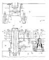
- FIG. 1is a cross-sectional view through one mold of an injection molding apparatus in a plane parallel to a direction in which the slides are moved, showing the mold in the closed position;
- FIG. 2is a cross-sectional view in the same plane as FIG. 1 showing the mold of FIG. 1 with the cavity plate separated from the stripper plate;
- FIG. 3is a cross-sectional view in the same plane as FIG. 1 showing the mold of FIG. 2 with the slides and the slide inserts moved laterally to their outer positions;
- FIG. 4is a cross-sectional view in the same plane as FIG. 1 showing the mold of FIG. 3 with the stripper plate separated from the core plate to advance the stripper ring along the machine axis and eject the molded part from the core;
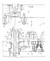
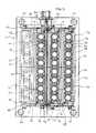
- FIG. 5is a top plan view of a molding apparatus of the present invention, partially disassembled to show details of the slide mechanism;
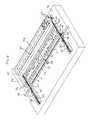
- FIG. 6is a perspective, partially cut away view of a partially disassembled molding apparatus of the present invention, illustrating the preferred slide mechanism, showing details of one pair of slide bars and one pair of slide inserts only;
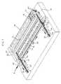
- FIG. 7is a perspective view similar to that of FIG. 6 illustrating the operation of the preferred slide mechanism
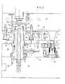
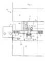
- FIG. 8is an enlarged cross-sectional view through the molding apparatus of FIG. 1 in a plane parallel to the driving rack, showing the sliding mechanism at the proximal end of the driving rack and omitting, for clarity, some of the teeth of the driving rack;
- FIG. 9is an isolated, enlarged cross-sectional view of the stripper plate and the slide mechanism of the molding apparatus of FIG. 1 in a plane perpendicular to the driving rack, showing the slide mechanism at the proximal end of the driving rack and omitting, for clarity, some of the teeth of the driven rack.
- a preferred molding apparatus according to the present inventionis generally indicated by reference numeral 10 in the drawings.
- the molding apparatus 10comprises three mold plates, namely a mold core plate 12 , a mold cavity plate 14 and a mold stripper plate 16 between the core plate 12 and cavity plate 14 .
- a mold core 18is mounted in the mold core plate 12
- a mold cavity 20is mounted in the mold cavity plate 14
- an annular stripper ring 22is mounted in the mold stripper plate 16 and surrounds the mold core 18 .
- Both the core plate 12 and stripper plate 16are movable along a machine axis to move the mold plates between a mold closed position and a mold open position.
- the stripper plate 16is movable along tie rods 24 (FIG. 5) relative to the core plate 12 in order to strip a molded part 26 from the core 18 .
- the stripper plate 16is preferably actuated by machine ejector rods (not shown) which advance the stripper plate 16 along the machine axis.
- the molded part 26 shown in the drawingscomprises a threaded closure for a container having a tamper-evident skirt which is separable from the remainder of closure 26 by a line of pre-weakening 27 .
- the molten plastic which forms molded part 26is injected into mold 28 through injection nozzle 38 .
- the cavity plate 14 and stripper plate 16abut each other at a first parting line P 1 in the mold closed position (FIG. 1), and the core plate 12 and the stripper plate 16 likewise abut each other along second parting line P 2 in the mold closed position.
- a mold 28is formed in which the molded part 26 is formed.
- the mold 28is formed between the mold core 18 and the mold cavity 20 .
- the radially inner portion of the upper surface of the stripper ring 22also forms part of mold 28 at the lower peripheral edge of the molded part 26 .
- the apparatus 10also comprises a plurality of laterally-movable mold elements.
- a pair of such mold elementsare provided for each mold 28 .
- each pair of laterally-movable mold elementscomprises slide inserts 30 and 32 mounted on slide bars 34 and 36 , respectively.
- the slide inserts 30 and 32are each semi-circular in shape and combine to form a split insert which combines with the stripper ring 22 , the core 18 and the cavity 20 to form mold 28 .
- the slide inserts 30 and 32each have a radially inner molding surface which is provided with an undercut portion to form the line of pre-weakening 27 separating the skirt from the main body of molded part 26 .
- the mold 28is opened and part 26 is removed from the mold 28 by first separating the cavity plate 14 from the stripper plate 16 (FIG. 2), laterally moving the slide inserts 30 and 32 and their associated slide bars 34 and 36 away from core 18 (FIG. 3), and then separating stripper plate 16 from core plate 12 (FIG. 4), thereby advancing stripper ring 22 along the machine axis to strip the part 26 from the core 12 .
- the molding apparatus 10preferably comprises a plurality of molds 28 as described above, to permit the simultaneous formation of a number of molded parts 26 .
- the molds 28are arranged in a plurality of spaced, parallel rows 40 .
- the mold apparatus 10comprises four rows 40 , each comprising eight molds 28 .
- mold apparatus 10is capable of simultaneously forming thirty-two molded parts 26 .
- the molding apparatus 10also comprises a slide mechanism for moving the slide inserts 30 and 32 between their inner positions (mold closed position) and their outer positions (FIGS. 3 and 4) in which they are separated from the molded part 26 .
- the slide mechanismincludes a driving rack 42 which is mounted in the stripper plate 16 .
- the driving rack 42comprises an elongate metal bar having a rectangular cross-section, and is provided along one edge with a plurality of teeth 44 .
- the driving rack 42has a proximal end 46 and a distal end 48 , the distance between the distal and proximal ends 46 and 48 being greater than the lengths of the rows 40 of molds 28 .
- the slide mechanismincludes driving means for producing reciprocating movement of the driving rack 42 along a lateral axis which is perpendicular to the machine axis and which is substantially parallel to the rows 40 of molds 28 .
- the driving meanspreferably comprises a pneumatic cylinder 50 (FIGS. 5 and 8) which is mounted to an outer surface of the stripper plate 16 .
- the driving meansmay comprise any means capable of actuating the driving rack, including hydraulic cylinders. Pneumatic cylinders are however preferred over hydraulic cylinders since leakage of fluid from hydraulic cylinders can cause contamination of the molded parts.
- drive pinions 52 and 54are mounted in the stripper plate 16 and are rotatable about an axis parallel to the machine axis. As shown in the drawings, the pinions 52 , 54 are each mounted on a guide bushing 53 , with each pinion and bushing 53 being retained by a pinion retainer plate 55 secured by screws to the stripper plate.
- the drive pinions 52 and 54are provided with gear teeth 56 which engage the teeth 44 on driving rack 42 such that movement of the driving rack 42 parallel to the rows 40 of molds 28 causes rotation of drive pinions 52 and 54 .
- movement of the driving rack 42 in the direction of arrow A in FIG. 7causes counter-clockwise rotation of pinions 52 , 54 and movement of driving rack 42 in the opposite direction causes clockwise rotation of drive pinions 52 and 54 .
- rollers 58are also mounted in the stripper plate 16 for rotation about an axis parallel to the machine axis. As shown in FIGS. 6 and 7, one or more rollers 58 may also be provided intermediate the ends 46 , 48 of driving rack 42 .
- the slide mechanismfurther comprises two pairs of driven racks 60 and 62 , each having one edge provided with teeth 61 and 63 , respectively. As shown in FIGS. 6 and 7 (in which one of the driven racks 62 is partially cut away), one pair of driven racks 60 , 62 engages the drive pinion 52 near the proximal end 46 of driving rack 42 for reciprocating movement along an axis which is perpendicular to the machine axis and perpendicular to the rows 40 of molds 28 in response to rotation of drive pinion 52 .
- the driven racks 60 and 62are spaced from one another and are substantially parallel so that they engage opposite sides of the drive pinion 52 .
- rotation of drive pinion 52results in movement of the driven racks 60 and 62 in opposite directions, as indicated by arrows B and C in FIG. 7. Specifically, when drive pinion 52 rotates in a counter-clockwise direction, rack 60 is driven to the left along arrow B and rack 62 is driven to the right along arrow C. Conversely, when drive pinion 52 rotates in the clockwise direction, rack 60 will be driven to the right and rack 62 will be driven to the left.
- driven racks 60 and 62are provided in engagement with drive pinion 54 at the distal end 48 of driving rack 42 . It will be appreciated that the driven racks 60 at the proximal and distal ends of driving rack 42 move in the same direction in response to rotation of drive pinions 52 and 54 , and that driven racks 62 at the opposite ends of driving rack 42 also move in the same direction.
- the two pairs of driven racks 60 , 62are separated by a distance which is greater than the lengths of the rows 40 and extend across the tops and bottoms of all of the rows 40 .
- the slide bars 34 and 36are mounted on the stripper plate 16 for reciprocal movement towards and away from the mold core 18 .
- the slide barsare movable along an axis which is perpendicular to the machine axis and which is also perpendicular to the rows 40 of molds 28 and to the longitudinal directions of the slide bars 34 , 36 .
- the slide bars 34 , 36extend across the two pairs of driven racks 60 , 62 , with the slide bar 34 being attached at its opposite ends to both driven racks 60 , and slide bar 36 being attached at its opposite ends to both driven racks 62 . Therefore, the slide bars 34 , 36 simultaneously move inward and outward in relation to the mold core 18 in response to movement of driven racks 60 and 62 in opposite directions.
- the slides 34 , 36are retained on pins 64 which project upwardly above the upper surfaces of driven racks 60 and 62 .
- the ends of the slide bars 34 , 36are prevented from being released from driven racks 60 , 62 by gibs 66 , 68 which are bolted to the stripper plate 16 at opposite ends of the slide bars 34 , 36 .
- Gib 68 near the distal end 48 of driving rack 42is shown partially cut away in FIG. 5.
- a series of locking wedgesincluding wedges 70 and 72 .
- the single acting locking wedge 70 and double acting locking wedge 72have sloped inner surfaces 76 and 78 (FIG. 2) respectively which engage sloped outer surfaces 80 and 82 (FIG. 2) of slide bars 34 and 36 respectively.
- the locking wedges 70 and 72firmly retain the slide bars 34 and 36 in place to prevent outward displacement of the slide bars and the slide inserts 30 and 32 .
- the cavity plate 14 and stripper plate 16are separated along parting line P 1 as shown in FIG. 2. As discussed above, this is preferably accomplished by mold opening along the machine axis, leaving the molded part 26 attached to the core 18 .
- the moldis again closed for the next molding operation by bringing core plate 12 and stripper plate 16 together along parting line P 2 , followed by activation of pneumatic cylinder 50 to move the driving rack 42 in the opposite direction to the mold opening step, resulting in movement of the slide bars 34 , 36 and slide inserts 30 , 32 to the inner position, and then bringing together the cavity plate 14 and stripper plate 16 along parting line P 1 , to close the mold 28 .
- actuation of the slide mechanismis independent of the opening and closing of the mold, the order of the above steps can be varied somewhat.
- the slide mechanismcould be actuated during mold opening and closing to further decrease the mold cycle time. This would not, however, require slowing down of the mold opening and closing step since the slide mechanism is operated independently.
- a molding apparatus according to the inventioncould be configured with only one drive pinion and one pair of driven racks, for example where the apparatus contains relatively few molds such that the slides are relatively short.
Landscapes
- Engineering & Computer Science (AREA)
- Manufacturing & Machinery (AREA)
- Mechanical Engineering (AREA)
- Moulds For Moulding Plastics Or The Like (AREA)
Abstract
Description
- The present invention relates to slide core molds for use in injection molding, and more specifically to slide mechanisms employed in such molds.[0001]
- Conventional molds for injection molding typically comprise mating parts, such as a core and a cavity, which abut each other at a parting line and are moved directly away from each other along a machine axis during opening of the mold.[0002]
- Such molds may also include one or more mold components which form an undercut portion of the article to be molded. These mold components, also referred to herein as “slide inserts”, are moved laterally into and out of engagement with the other mating parts of the mold during closing and opening of the mold. Usually, a pair of such slide inserts is provided, one slide insert on each side of the mold. During mold opening, the slide inserts are moved outwardly in opposite directions from the other mating parts of the mold. Molds which include such laterally movable components are referred to herein as “slide core molds”.[0003]
- Presently used mechanisms for opening and closing slide core molds typically include slide blocks on which the slide inserts are mounted. Usually, these slide blocks are slidably mounted on the mold plate which carries the core, with one slide block being provided on each side of the mold. Lateral movement of the slide blocks is accomplished by providing angled horn pins mounted to the mold plate which carries the cavity. The horn pins extend through angled apertures in the slide blocks. As the core is separated from the cavity, the slide blocks slide along the horn pins, resulting in outward displacement of the slide blocks and the associated slide inserts from the other mating parts of the mold. Examples of this type of mechanism are described in U.S. Pat. No. 3,811,645 issued May 21, 1974 to Feist and U.S. Pat. No. 4,889,480 issued Dec. 26, 1989 to Nakamura et al. These two patents are actually concerned with slide retainers which are required in this type of slide core mold since the horn pins and the apertures in the slide blocks may become misaligned when the mold is opened, preventing reinsertion of the horn pins into the slide blocks.[0004]
- Conventional slide mechanisms have several disadvantages. Firstly, conventional slide mechanisms include components such as cams which must be mounted on the outside of the mold and which increase the size of the mold. Some conventional slide retainers, such as the pull rod/compression spring retainer shown in FIG. 2 of the Feist patent, also include components which project from the sides of the mold. These components have the effect of enlarging the mold, reducing the number of mold cavities which can be fitted into a molding apparatus of a given size.[0005]
- In addition, components such as cams and/or horn pins project from the parting line face and obstruct the space between the mold plates during ejection of the molded parts from the core. Since these components are lubricated, contact with the molded parts during ejection can result in product contamination.[0006]
- Another disadvantage of conventional slide mechanisms is that these mechanisms are actuated as the mold opens and closes. This requires that the opening and closing of the mold be slowed down In order to avoid damaging the relatively delicate slide inserts, thereby lengthening the mold cycle time.[0007]
- Therefore, the need exists for an effective slide mechanism which eliminates or reduces the size and/or number of components projecting from the outside of the mold. It would also be desirable to provide a slide mechanism which eliminates the need for a slide retainer to reduce the size and complexity of the mechanism, which also eliminates obstructions between the mold plates, and which can be actuated independently of opening and closing the mold.[0008]
- The present invention overcomes at least some of the disadvantages of the prior art by providing a molding apparatus having a slide mechanism which is more compact than conventional slide mechanisms, does not form obstructions between the open mold plates, eliminates the need for slide retainers, and does not depend on mold opening and closing for actuation.[0009]
- The molding apparatus according to the present invention comprises at least two mold plates which preferably carry a plurality of mold cores and mating mold cavities which form a plurality of molds. Each mold has a pair of laterally movable mold elements which are movable toward and away from each other. The mold elements of each mold are mounted on a pair of slides positioned on either side of the mold.[0010]
- The mechanism for moving the mold elements between their inner and outer positions includes a reciprocating driving rack which drives at least one pinion. Each pinion drives a pair of driven racks which are movable in opposite directions, each of the racks being connected to one of the slides. Therefore, movement of the driving rack results in lateral movement of the slides and the associated mold components inwardly or outwardly in relation to the mold.[0011]
- Since the apparatus of the invention does not utilize horn pins, misalignment of the slides during opening and closing is not a problem, and therefore slide retainers are not required. The slide mechanism of the present invention is compact and is recessed into the stripper plate, away from the mold parting line. This reduces the overall size of the mold and eliminates obstructions between the mold plates, thereby reducing the risk of contamination of parts being ejected from the molds. Furthermore, the slide mechanism does not rely on mold opening and closing for actuation since the driven racks are preferably actuated by a pneumatic cylinder after the mold is opened and retracted before it is closed, thereby allowing a shorter mold cycle time.[0012]
- The invention will now be described, by way of example only, with reference to the accompanying drawings in which:[0013]
- FIG. 1 is a cross-sectional view through one mold of an injection molding apparatus in a plane parallel to a direction in which the slides are moved, showing the mold in the closed position;[0014]
- FIG. 2 is a cross-sectional view in the same plane as FIG. 1 showing the mold of FIG. 1 with the cavity plate separated from the stripper plate;[0015]
- FIG. 3 is a cross-sectional view in the same plane as FIG. 1 showing the mold of FIG. 2 with the slides and the slide inserts moved laterally to their outer positions;[0016]
- FIG. 4 is a cross-sectional view in the same plane as FIG. 1 showing the mold of FIG. 3 with the stripper plate separated from the core plate to advance the stripper ring along the machine axis and eject the molded part from the core;[0017]
- FIG. 5 is a top plan view of a molding apparatus of the present invention, partially disassembled to show details of the slide mechanism;[0018]
- FIG. 6 is a perspective, partially cut away view of a partially disassembled molding apparatus of the present invention, illustrating the preferred slide mechanism, showing details of one pair of slide bars and one pair of slide inserts only;[0019]
- FIG. 7 is a perspective view similar to that of FIG. 6 illustrating the operation of the preferred slide mechanism;[0020]
- FIG. 8 is an enlarged cross-sectional view through the molding apparatus of FIG. 1 in a plane parallel to the driving rack, showing the sliding mechanism at the proximal end of the driving rack and omitting, for clarity, some of the teeth of the driving rack; and[0021]
- FIG. 9 is an isolated, enlarged cross-sectional view of the stripper plate and the slide mechanism of the molding apparatus of FIG. 1 in a plane perpendicular to the driving rack, showing the slide mechanism at the proximal end of the driving rack and omitting, for clarity, some of the teeth of the driven rack.[0022]
- A preferred molding apparatus according to the present invention is generally indicated by[0023]
reference numeral 10 in the drawings. Themolding apparatus 10 comprises three mold plates, namely amold core plate 12, amold cavity plate 14 and amold stripper plate 16 between thecore plate 12 andcavity plate 14. Amold core 18 is mounted in themold core plate 12, amold cavity 20 is mounted in themold cavity plate 14, and anannular stripper ring 22 is mounted in themold stripper plate 16 and surrounds themold core 18. - Both the[0024]
core plate 12 andstripper plate 16 are movable along a machine axis to move the mold plates between a mold closed position and a mold open position. Thestripper plate 16 is movable along tie rods24 (FIG. 5) relative to thecore plate 12 in order to strip amolded part 26 from thecore 18. Thestripper plate 16 is preferably actuated by machine ejector rods (not shown) which advance thestripper plate 16 along the machine axis. - The molded[0025]
part 26 shown in the drawings comprises a threaded closure for a container having a tamper-evident skirt which is separable from the remainder ofclosure 26 by a line of pre-weakening27. The molten plastic which forms moldedpart 26 is injected intomold 28 throughinjection nozzle 38. - The[0026]
cavity plate 14 andstripper plate 16 abut each other at a first parting line P1 in the mold closed position (FIG. 1), and thecore plate 12 and thestripper plate 16 likewise abut each other along second parting line P2 in the mold closed position. With theplates mold 28 is formed in which themolded part 26 is formed. Themold 28 is formed between themold core 18 and themold cavity 20. The radially inner portion of the upper surface of thestripper ring 22 also forms part ofmold 28 at the lower peripheral edge of themolded part 26. - As illustrated in the drawings, the[0027]
apparatus 10 also comprises a plurality of laterally-movable mold elements. A pair of such mold elements are provided for eachmold 28. In the preferred embodiment shown in the drawings, each pair of laterally-movable mold elements comprises slide inserts30 and32 mounted onslide bars stripper ring 22, thecore 18 and thecavity 20 to formmold 28. In the preferred embodiments shown in the drawings, the slide inserts30 and32 each have a radially inner molding surface which is provided with an undercut portion to form the line of pre-weakening27 separating the skirt from the main body of moldedpart 26. - The[0028]
mold 28 is opened andpart 26 is removed from themold 28 by first separating thecavity plate 14 from the stripper plate16 (FIG. 2), laterally moving the slide inserts30 and32 and their associated slide bars34 and36 away from core18 (FIG. 3), and then separatingstripper plate 16 from core plate12 (FIG. 4), thereby advancingstripper ring 22 along the machine axis to strip thepart 26 from thecore 12. These steps will be described in greater detail below. - As illustrated in the plan view of FIG. 5, the[0029]
molding apparatus 10 preferably comprises a plurality ofmolds 28 as described above, to permit the simultaneous formation of a number of moldedparts 26. Preferably, themolds 28 are arranged in a plurality of spaced,parallel rows 40. In thepreferred apparatus 10 shown in the drawings, themold apparatus 10 comprises fourrows 40, each comprising eightmolds 28. Thus,mold apparatus 10 is capable of simultaneously forming thirty-two moldedparts 26. - In the[0030]
leftmost row 40 ofmolds 28 in FIG. 5, the slide bars34,36 have been omitted to reveal a pair ofapertured wear plates 41 which are bolted to thestripper plate 16. The edges ofwear plates 41 are also visible in theother rows 40. Thewear plates 41 underlie the slide bars34,36 and are provided withapertures 43 which surround the stripper rings22 and themold cores 18, this being illustrated in FIGS.1 to4. - The[0031]
molding apparatus 10 also comprises a slide mechanism for moving the slide inserts30 and32 between their inner positions (mold closed position) and their outer positions (FIGS. 3 and 4) in which they are separated from the moldedpart 26. - The slide mechanism includes a[0032]
driving rack 42 which is mounted in thestripper plate 16. Thedriving rack 42 comprises an elongate metal bar having a rectangular cross-section, and is provided along one edge with a plurality ofteeth 44. Thedriving rack 42 has aproximal end 46 and adistal end 48, the distance between the distal and proximal ends46 and48 being greater than the lengths of therows 40 ofmolds 28. - The slide mechanism includes driving means for producing reciprocating movement of the[0033]
driving rack 42 along a lateral axis which is perpendicular to the machine axis and which is substantially parallel to therows 40 ofmolds 28. The driving means preferably comprises a pneumatic cylinder50 (FIGS. 5 and 8) which is mounted to an outer surface of thestripper plate 16. It will be appreciated that the driving means may comprise any means capable of actuating the driving rack, including hydraulic cylinders. Pneumatic cylinders are however preferred over hydraulic cylinders since leakage of fluid from hydraulic cylinders can cause contamination of the molded parts. - Provided near the respective ends[0034]46 and48 of driving
rack 42 are a pair of drive pinions52 and54. The drive pinions52 and54 are mounted in thestripper plate 16 and are rotatable about an axis parallel to the machine axis. As shown in the drawings, thepinions guide bushing 53, with each pinion andbushing 53 being retained by apinion retainer plate 55 secured by screws to the stripper plate. The drive pinions52 and54 are provided withgear teeth 56 which engage theteeth 44 on drivingrack 42 such that movement of thedriving rack 42 parallel to therows 40 ofmolds 28 causes rotation of drive pinions52 and54. Specifically, movement of thedriving rack 42 in the direction of arrow A in FIG. 7 causes counter-clockwise rotation ofpinions rack 42 in the opposite direction causes clockwise rotation of drive pinions52 and54. - Preferably, engagement between the driving[0035]
rack 42 and the drive pinions52,54 is maintained byrollers 58 provided near each of the drive pinions52 and54.Rollers 58 are also mounted in thestripper plate 16 for rotation about an axis parallel to the machine axis. As shown in FIGS. 6 and 7, one ormore rollers 58 may also be provided intermediate theends rack 42. - The slide mechanism further comprises two pairs of driven[0036]
racks teeth racks 62 is partially cut away), one pair of drivenracks drive pinion 52 near theproximal end 46 of drivingrack 42 for reciprocating movement along an axis which is perpendicular to the machine axis and perpendicular to therows 40 ofmolds 28 in response to rotation ofdrive pinion 52. The driven racks60 and62 are spaced from one another and are substantially parallel so that they engage opposite sides of thedrive pinion 52. Therefore, rotation ofdrive pinion 52 results in movement of the drivenracks drive pinion 52 rotates in a counter-clockwise direction,rack 60 is driven to the left along arrow B andrack 62 is driven to the right along arrow C. Conversely, whendrive pinion 52 rotates in the clockwise direction, rack60 will be driven to the right andrack 62 will be driven to the left. - An identical pair of driven[0037]
racks drive pinion 54 at thedistal end 48 of drivingrack 42. It will be appreciated that the drivenracks 60 at the proximal and distal ends of drivingrack 42 move in the same direction in response to rotation of drive pinions52 and54, and that drivenracks 62 at the opposite ends of drivingrack 42 also move in the same direction. - As illustrated in the plan view of FIG. 5, the two pairs of driven[0038]
racks rows 40 and extend across the tops and bottoms of all of therows 40. - The slide bars[0039]34 and36 are mounted on the
stripper plate 16 for reciprocal movement towards and away from themold core 18. The slide bars are movable along an axis which is perpendicular to the machine axis and which is also perpendicular to therows 40 ofmolds 28 and to the longitudinal directions of the slide bars34,36. As shown in FIGS. 6 and 7, the slide bars34,36 extend across the two pairs of drivenracks slide bar 34 being attached at its opposite ends to both drivenracks 60, and slidebar 36 being attached at its opposite ends to both driven racks62. Therefore, the slide bars34,36 simultaneously move inward and outward in relation to themold core 18 in response to movement of drivenracks - As illustrated in FIG. 6 to[0040]8, the
slides pins 64 which project upwardly above the upper surfaces of drivenracks racks stripper plate 16 at opposite ends of the slide bars34,36. Gib68 near thedistal end 48 of drivingrack 42 is shown partially cut away in FIG. 5. - As best illustrated in FIGS. 1 and 2, provided along the first parting line P[0041]1 is a series of locking wedges, including
wedges acting locking wedge 70 and doubleacting locking wedge 72 have slopedinner surfaces 76 and78 (FIG. 2) respectively which engage slopedouter surfaces 80 and82 (FIG. 2) of slide bars34 and36 respectively. Thus, when the cavity plate2514 andstripper plate 16 abut one another in the mold closed position of FIG. 1, the lockingwedges - A molding[0042]
operation utilizing apparatus 10 will now be described below with reference to the drawings. - With the[0043]
mold 28 in the mold closed position as shown in FIG. 1, molten plastic is injected under pressure intomold 28 frominjection nozzle 38 to form moldedpart 26. The mold is subsequently opened and the part ejected by the following sequence of steps: - 1. The[0044]
cavity plate 14 andstripper plate 16 are separated along parting line P1 as shown in FIG. 2. As discussed above, this is preferably accomplished by mold opening along the machine axis, leaving the moldedpart 26 attached to thecore 18. - 2. With the mold open along parting line P[0045]1 and locking wedges withdrawn as in FIG. 2, the
pneumatic cylinder 50 is activated to push thedriving rack 42 in a direction away fromcylinder 50, thereby causing rotation ofpinions racks - 3. With the slide bars[0046]34 and36 and associated slide inserts30 and32 moved to the outer positions as shown in FIG. 3, the
stripper ring 22 is advanced axially upward by separation ofstripper plate 16 fromcore plate 12, thereby ejecting the moldedpart 26 fromcore 18 as shown in FIG. 4. - The mold is again closed for the next molding operation by bringing[0047]
core plate 12 andstripper plate 16 together along parting line P2, followed by activation ofpneumatic cylinder 50 to move thedriving rack 42 in the opposite direction to the mold opening step, resulting in movement of the slide bars34,36 and slide inserts30,32 to the inner position, and then bringing together thecavity plate 14 andstripper plate 16 along parting line P1, to close themold 28. - Since actuation of the slide mechanism is independent of the opening and closing of the mold, the order of the above steps can be varied somewhat. For example, the slide mechanism could be actuated during mold opening and closing to further decrease the mold cycle time. This would not, however, require slowing down of the mold opening and closing step since the slide mechanism is operated independently.[0048]
- Although the invention has been described in connection with a molding apparatus having a certain number of molds, it will be appreciated that the invention can be applied to a molding apparatus having any number of molds, including an apparatus having only one mold.[0049]
- Although the invention has been described in connection with a molding apparatus which utilizes a stripper plate and a stripper ring, it will be appreciated that the present invention could be applied to a molding apparatus having two mold plates which form a one or more molds, with the slide mechanism of the present invention could be mounted in either of the mold plates.[0050]
- It is also conceivable that a molding apparatus according to the invention could be configured with only one drive pinion and one pair of driven racks, for example where the apparatus contains relatively few molds such that the slides are relatively short.[0051]
- Although the invention has been described in connection with certain preferred embodiments, it is not to be limited thereto. Rather, the invention is intended to encompass all embodiments which may fall within the scope of the following claims.[0052]
Claims (18)
Priority Applications (5)
| Application Number | Priority Date | Filing Date | Title |
|---|---|---|---|
| US09/795,150US6450797B1 (en) | 2001-03-01 | 2001-03-01 | Compact slide actuation mold |
| CA002348830ACA2348830C (en) | 2001-03-01 | 2001-05-29 | Compact slide actuation mold |
| PCT/CA2002/000239WO2002070227A1 (en) | 2001-03-01 | 2002-02-22 | Compact slide actuation mold |
| BR0204224-0ABR0204224A (en) | 2001-03-01 | 2002-02-22 | Compact sliding plate activation mold |
| MXPA03007808AMXPA03007808A (en) | 2001-03-01 | 2002-02-22 | Compact slide actuation mold. |
Applications Claiming Priority (1)
| Application Number | Priority Date | Filing Date | Title |
|---|---|---|---|
| US09/795,150US6450797B1 (en) | 2001-03-01 | 2001-03-01 | Compact slide actuation mold |
Publications (2)
| Publication Number | Publication Date |
|---|---|
| US20020122841A1true US20020122841A1 (en) | 2002-09-05 |
| US6450797B1 US6450797B1 (en) | 2002-09-17 |
Family
ID=25164826
Family Applications (1)
| Application Number | Title | Priority Date | Filing Date |
|---|---|---|---|
| US09/795,150Expired - LifetimeUS6450797B1 (en) | 2001-03-01 | 2001-03-01 | Compact slide actuation mold |
Country Status (3)
| Country | Link |
|---|---|
| US (1) | US6450797B1 (en) |
| CA (1) | CA2348830C (en) |
| WO (1) | WO2002070227A1 (en) |
Cited By (12)
| Publication number | Priority date | Publication date | Assignee | Title |
|---|---|---|---|---|
| ES2222815A1 (en)* | 2003-07-24 | 2005-02-01 | Industrial De Moldes Y Matrices, S.A. | Apparatus for the production of preforms by means of moulding |
| EP2150388A4 (en)* | 2007-04-26 | 2010-11-24 | Husky Injection Molding | APPLICATION FOR MULTIPLE TOOL FOR A FORMING SYSTEM |
| WO2011130847A1 (en)* | 2010-04-23 | 2011-10-27 | Husky Injection Molding Systems Ltd. | Molding apparatus |
| US20130071512A1 (en)* | 2010-06-11 | 2013-03-21 | Irumold S.L. | Opening device of slides in moulds for the ejection of moulded parts |
| US20150209989A1 (en)* | 2014-01-28 | 2015-07-30 | Comercial De Utiles Y Moldes, S.A. | Device for demolding parts |
| EP2957410A1 (en)* | 2014-06-19 | 2015-12-23 | Infiplast | Retractable ring system for moulding parts |
| US20180133941A1 (en)* | 2016-11-16 | 2018-05-17 | Yong-Hoon Hur | Injection apparatus for molding combined member of constant-velocity joint boot, injection method of combined member of constant-velocity joint boot, and constant-velocity joint boot manufactured by injection method of combined member |
| WO2020118413A1 (en)* | 2018-12-11 | 2020-06-18 | Husky Injection Molding Systems Ltd. | Injection mold directing clamping load through mold stacks |
| CN113386305A (en)* | 2020-03-11 | 2021-09-14 | 华为技术有限公司 | Die and processing method |
| USD958209S1 (en) | 2019-06-04 | 2022-07-19 | Husky Injection Molding Systems Ltd. | Molding machine part |
| CN116238117A (en)* | 2023-02-09 | 2023-06-09 | 创意塑胶工业(苏州)有限公司 | A demoulding mechanism for an injection mold |
| CN117698074A (en)* | 2024-01-15 | 2024-03-15 | 湖南承运机电有限公司 | Injection mold device for mobile phone charger shell and application method thereof |
Families Citing this family (22)
| Publication number | Priority date | Publication date | Assignee | Title |
|---|---|---|---|---|
| US6799962B2 (en)* | 2001-04-09 | 2004-10-05 | Husky Injection Molding Systems Ltd. | Stripper assembly |
| US6592797B2 (en)* | 2001-06-28 | 2003-07-15 | The Tech Group, Inc. | Method and apparatus to reduce galling in a mold device |
| FR2832951B1 (en)* | 2001-12-05 | 2004-05-14 | Curtil Sa | INJECTION MODULE FOR PLASTIC CAPS WITH TROLLEY |
| US7128564B2 (en)* | 2003-12-11 | 2006-10-31 | Husky Injection Molding Systems Ltd. | Simplified in-mold article handling system and a method for handling molded articles |
| EP1697105A4 (en)* | 2003-12-23 | 2007-09-19 | Decoma Int Inc | Article, method and apparatus of forming expanded plastic materials in a steam chest mold |
| US7240719B2 (en)* | 2004-09-08 | 2007-07-10 | Qx, Inc. | Die-casting systems and methods |
| US20060279023A1 (en)* | 2005-06-08 | 2006-12-14 | Walsh Thomas J | Precision loader of injection molds |
| JP2007112118A (en)* | 2005-09-22 | 2007-05-10 | Igari Mold Kk | Mold assembly for molding blow molded product and molding method of blow molded product |
| CN1951668B (en)* | 2005-10-21 | 2010-05-05 | 鸿富锦精密工业(深圳)有限公司 | Plastic jet mould |
| CN1986192B (en)* | 2005-12-23 | 2010-05-26 | 鸿富锦精密工业(深圳)有限公司 | Plastic Injection Mold |
| US7381049B2 (en)* | 2006-03-08 | 2008-06-03 | Husky Injection Molding Systems Ltd. | Injection mold |
| EP1905566B1 (en)* | 2006-09-26 | 2009-11-11 | GEFIT S.p.A. | Mould for manufacturing sealing caps |
| US20080268090A1 (en)* | 2007-04-26 | 2008-10-30 | Husky Injection Molding Systems Ltd. | Slide Assembly for a Molding System |
| US7575429B2 (en) | 2007-07-20 | 2009-08-18 | Husky Injection Molding Systems Ltd. | Compensating mold stack for use in a molding system |
| US7588439B2 (en) | 2007-07-20 | 2009-09-15 | Husky Injection Molding Systems Ltd. | Compensating core for use with a molding system |
| US7597551B2 (en) | 2007-07-20 | 2009-10-06 | Husky Injection Molding Systems Ltd. | Compensating retaining member for use with a molding system |
| US7628605B2 (en) | 2007-07-20 | 2009-12-08 | Husky Injection Molding Systems Ltd. | Mold stack |
| CN103934993B (en) | 2009-11-30 | 2017-01-18 | 赫斯基注塑系统有限公司 | A molded article transfer device with shuttling movement |
| EP2418068B1 (en) | 2010-08-10 | 2016-11-09 | Mold-Masters (2007) Limited | Quick-change molding system for injection molding |
| CN103747936B (en) | 2011-08-30 | 2016-10-05 | 赫斯基注塑系统有限公司 | A kind of stripper sleeve |
| EP3936301A1 (en) | 2015-07-08 | 2022-01-12 | Husky Injection Molding Systems Luxembourg IP Development S.à.r.l | Injection molding apparatuses |
| CN107856254B (en)* | 2017-12-22 | 2023-12-05 | 宁波华翔汽车饰件有限公司 | Oiling small door base mold and molding method |
Family Cites Families (21)
| Publication number | Priority date | Publication date | Assignee | Title |
|---|---|---|---|---|
| US447675A (en) | 1891-03-03 | frank | ||
| US829380A (en) | 1905-10-30 | 1906-08-28 | Samuel R Ball | Concrete-block-molding mechanism. |
| US1335525A (en) | 1919-09-20 | 1920-03-30 | Fred Ellsworth | Block-mold |
| US2047379A (en) | 1934-01-11 | 1936-07-14 | Western Electric Co | Molding die |
| US2076377A (en) | 1934-07-31 | 1937-04-06 | Loewenstein Ludwig | Apparatus for molding frozen confections |
| US3650653A (en) | 1969-10-13 | 1972-03-21 | Gerald Erickson | Mold assembly for molding chimed containers |
| US3811645A (en) | 1973-01-05 | 1974-05-21 | K Feist | Slide retainer and positioner |
| US4140464A (en) | 1977-06-13 | 1979-02-20 | Emhart Industries, Inc. | Machine system for formation of molecularly oriented plastic bottles |
| US4207051A (en) | 1979-01-11 | 1980-06-10 | Husky Injection Molding Systems Limited | Stripper mechanism for injection mold |
| DE2917799C2 (en) | 1979-05-03 | 1981-04-23 | HASCO-Normalien Hasenclever & Co, 5880 Lüdenscheid | Plastic injection mold or compression mold with a displaceably guided molded part |
| US4718845A (en) | 1986-04-02 | 1988-01-12 | James Sheffield | Rack and pinion gear stack mold control |
| DE3614119A1 (en) | 1986-04-25 | 1987-10-29 | Kunststoffwerke Adolf Hopf Gmb | Device for demoulding an injection-moulded part |
| AU606482B2 (en) | 1988-11-22 | 1991-02-07 | Sankyo Engineering Co., Ltd. | Slide core mold for injection molding |
| US4998875A (en) | 1990-02-28 | 1991-03-12 | D & L Incorporated | Mold with slide retainer |
| US5312243A (en) | 1992-04-01 | 1994-05-17 | Mertz James E | Slide retainer for an injection mold |
| US6171094B1 (en) | 1993-11-01 | 2001-01-09 | John W. Von Holdt | Universal mold |
| DE19539752C2 (en) | 1995-10-26 | 1999-09-23 | Ferromatik Milacron Maschinenb | Tie-bar-less two-plate injection molding machine |
| US5776521A (en)* | 1996-05-14 | 1998-07-07 | Zygo Mould Limited | Apparatus for forming threaded moulded articles |
| US5908597A (en) | 1997-04-18 | 1999-06-01 | Husky Injection Molding Systems Ltd. | Ejection methods and linkage apparatus for stack molds |
| NL1005970C2 (en) | 1997-05-05 | 1998-11-09 | Inter Tooling Services Bv | Injection molding device for hollow objects such as, for example, pipe fittings. |
| US6238202B1 (en)* | 1999-02-26 | 2001-05-29 | Unique Mould Makers Limited | Apparatus for ejecting threaded injection molded parts |
- 2001
- 2001-03-01USUS09/795,150patent/US6450797B1/ennot_activeExpired - Lifetime
- 2001-05-29CACA002348830Apatent/CA2348830C/ennot_activeExpired - Lifetime
- 2002
- 2002-02-22WOPCT/CA2002/000239patent/WO2002070227A1/ennot_activeApplication Discontinuation
Cited By (27)
| Publication number | Priority date | Publication date | Assignee | Title |
|---|---|---|---|---|
| ES2222815A1 (en)* | 2003-07-24 | 2005-02-01 | Industrial De Moldes Y Matrices, S.A. | Apparatus for the production of preforms by means of moulding |
| WO2005009718A1 (en)* | 2003-07-24 | 2005-02-03 | Industrial De Moldes Y Matrices, Sa | Apparatus for the production of preforms by means of moulding |
| ES2222815B1 (en)* | 2003-07-24 | 2005-10-16 | Industrial De Moldes Y Matrices, S.A. | APPARATUS FOR THE MANUFACTURE OF PREFORMS BY MOLDING. |
| EP2150388A4 (en)* | 2007-04-26 | 2010-11-24 | Husky Injection Molding | APPLICATION FOR MULTIPLE TOOL FOR A FORMING SYSTEM |
| WO2011130847A1 (en)* | 2010-04-23 | 2011-10-27 | Husky Injection Molding Systems Ltd. | Molding apparatus |
| US8834149B2 (en) | 2010-04-23 | 2014-09-16 | Husky Injection Molding Systems Ltd. | Molding apparatus |
| US20130071512A1 (en)* | 2010-06-11 | 2013-03-21 | Irumold S.L. | Opening device of slides in moulds for the ejection of moulded parts |
| EP2581198A4 (en)* | 2010-06-11 | 2015-01-21 | Irumold S L | System for opening movable elements in moulds in order to extract the moulded parts |
| US20150209989A1 (en)* | 2014-01-28 | 2015-07-30 | Comercial De Utiles Y Moldes, S.A. | Device for demolding parts |
| US9308681B2 (en)* | 2014-01-28 | 2016-04-12 | Comercial De Utiles Y Moldes, S.A. | Device for demolding parts |
| EP2957410A1 (en)* | 2014-06-19 | 2015-12-23 | Infiplast | Retractable ring system for moulding parts |
| FR3022483A1 (en)* | 2014-06-19 | 2015-12-25 | Infiplast | RETRACTABLE CORE SYSTEM FOR MOLDING WORKPIECES |
| US20180133941A1 (en)* | 2016-11-16 | 2018-05-17 | Yong-Hoon Hur | Injection apparatus for molding combined member of constant-velocity joint boot, injection method of combined member of constant-velocity joint boot, and constant-velocity joint boot manufactured by injection method of combined member |
| US10663007B2 (en)* | 2016-11-16 | 2020-05-26 | Yong-Hoon Hur | Injection apparatus for molding combined member of constant-velocity joint boot, injection method of combined member of constant-velocity joint boot, and constant-velocity joint boot manufactured by injection method of combined member |
| WO2020118413A1 (en)* | 2018-12-11 | 2020-06-18 | Husky Injection Molding Systems Ltd. | Injection mold directing clamping load through mold stacks |
| CN111300764A (en)* | 2018-12-11 | 2020-06-19 | 赫斯基注塑系统有限公司 | Dies, Die Assemblies and Stacked Parts |
| US11806905B2 (en) | 2018-12-11 | 2023-11-07 | Husky Injection Molding Systems Ltd | Molds, mold assemblies and stack components |
| USD986934S1 (en) | 2019-06-04 | 2023-05-23 | Husky Injection Molding Systems Ltd. | Molding machine part |
| USD958207S1 (en) | 2019-06-04 | 2022-07-19 | Husky Injection Molding Systems Ltd. | Molding machine part |
| USD958206S1 (en) | 2019-06-04 | 2022-07-19 | Husky Injection Molding Systems Ltd. | Molding machine part |
| USD958208S1 (en) | 2019-06-04 | 2022-07-19 | Husky Injection Molding Systems Ltd. | Molding machine part |
| USD958205S1 (en) | 2019-06-04 | 2022-07-19 | Husky Injection Molding Systems Ltd. | Molding machine part |
| USD958209S1 (en) | 2019-06-04 | 2022-07-19 | Husky Injection Molding Systems Ltd. | Molding machine part |
| USD986933S1 (en) | 2019-06-04 | 2023-05-23 | Husky Injection Molding Systems Ltd. | Molding machine part |
| CN113386305A (en)* | 2020-03-11 | 2021-09-14 | 华为技术有限公司 | Die and processing method |
| CN116238117A (en)* | 2023-02-09 | 2023-06-09 | 创意塑胶工业(苏州)有限公司 | A demoulding mechanism for an injection mold |
| CN117698074A (en)* | 2024-01-15 | 2024-03-15 | 湖南承运机电有限公司 | Injection mold device for mobile phone charger shell and application method thereof |
Also Published As
| Publication number | Publication date |
|---|---|
| WO2002070227A1 (en) | 2002-09-12 |
| US6450797B1 (en) | 2002-09-17 |
| CA2348830C (en) | 2009-09-08 |
| CA2348830A1 (en) | 2002-09-01 |
Similar Documents
| Publication | Publication Date | Title |
|---|---|---|
| US6450797B1 (en) | Compact slide actuation mold | |
| US4330257A (en) | Turret-type injection-molding machine | |
| US9266265B2 (en) | Molding apparatus | |
| US4243362A (en) | Composite molding apparatus for articles from two materials having a rotary mold block which includes pins for providing core areas | |
| US4118168A (en) | Guidance system for shallow articles discharged from a mold cavity | |
| KR101205686B1 (en) | A mold stack for a preform | |
| CN102858514B (en) | Molding apparatus | |
| US6398537B2 (en) | Shuttle system for an apparatus for injection molding | |
| US5051227A (en) | Production of preforms and blow molded articles | |
| WO2021121977A1 (en) | Tool and method for injection moulding an injection-moulded part in a tool | |
| KR102187481B1 (en) | Control method for injection molds and injection molds for manufacturing injection products with upper/lower undercuts | |
| JPS63188033A (en) | Molding method for synthetic resin product | |
| US20030146546A1 (en) | Injection mold for plastic caps, with carriage | |
| AT523705B1 (en) | Injection molding machine for casting preforms | |
| JP2002347085A (en) | Injection-molding mold | |
| KR100550532B1 (en) | Injection mold of deformation core method and injection method | |
| MXPA03007808A (en) | Compact slide actuation mold. | |
| KR100203397B1 (en) | Eject Device for Molded Products_ | |
| JPH02164509A (en) | Injection die | |
| CN219484160U (en) | Forming die | |
| KR101196521B1 (en) | Apparatus for actuating slide in injection molding | |
| US20240335983A1 (en) | Collapsing core mould | |
| WO2016090464A1 (en) | Mold slide actuator and mold incorporating same | |
| JP7260931B2 (en) | Undercut processing mechanism and mold for molding | |
| JPH038405Y2 (en) |
Legal Events
| Date | Code | Title | Description |
|---|---|---|---|
| AS | Assignment | Owner name:UNIQUE MOULD MAKERS LIMITED, ONTARIO Free format text:ASSIGNMENT OF ASSIGNORS INTEREST;ASSIGNOR:JOSEPH, EALIAS C.;REEL/FRAME:011623/0902 Effective date:20010226 | |
| AS | Assignment | Owner name:STACKTECK SYSTEMS CANADA INC., ONTARIO Free format text:MERGER;ASSIGNOR:UNIQUE MOULD MAKERS LIMITED;REEL/FRAME:013129/0540 Effective date:20001201 Owner name:STACKTECK SYSTEMS LIMITED, ONTARIO Free format text:CHANGE OF NAME;ASSIGNOR:STACKTECK SYSTEMS CANADA INC.;REEL/FRAME:013129/0534 Effective date:20020417 | |
| STCF | Information on status: patent grant | Free format text:PATENTED CASE | |
| AS | Assignment | Owner name:WOODSIDE AGENCY SERVICES, LLC, AS U.S. AGENT, MASS Free format text:SECURITY AGREEMENT;ASSIGNOR:STACKTECK SYSTEMS LIMITED;REEL/FRAME:016038/0099 Effective date:20050301 | |
| FEPP | Fee payment procedure | Free format text:PAYOR NUMBER ASSIGNED (ORIGINAL EVENT CODE: ASPN); ENTITY STATUS OF PATENT OWNER: SMALL ENTITY | |
| FPAY | Fee payment | Year of fee payment:4 | |
| FPAY | Fee payment | Year of fee payment:8 | |
| FPAY | Fee payment | Year of fee payment:12 |