US20020104942A1 - Apparatus and method for adapting two-post rack systems to support four-post rack mounted equipment - Google Patents
Apparatus and method for adapting two-post rack systems to support four-post rack mounted equipmentDownload PDFInfo
- Publication number
- US20020104942A1 US20020104942A1US10/008,766US876601AUS2002104942A1US 20020104942 A1US20020104942 A1US 20020104942A1US 876601 AUS876601 AUS 876601AUS 2002104942 A1US2002104942 A1US 2002104942A1
- Authority
- US
- United States
- Prior art keywords
- post
- rack
- coupling
- coupling member
- equipment
- Prior art date
- Legal status (The legal status is an assumption and is not a legal conclusion. Google has not performed a legal analysis and makes no representation as to the accuracy of the status listed.)
- Granted
Links
- 238000000034methodMethods0.000titleclaimsabstractdescription45
- 230000008878couplingEffects0.000claimsabstractdescription237
- 238000010168coupling processMethods0.000claimsabstractdescription237
- 238000005859coupling reactionMethods0.000claimsabstractdescription237
- 238000012546transferMethods0.000claimsabstractdescription6
- 230000003362replicative effectEffects0.000claimsdescription13
- 230000001154acute effectEffects0.000claimsdescription5
- 238000009423ventilationMethods0.000claimsdescription2
- 230000008901benefitEffects0.000description7
- 230000000712assemblyEffects0.000description6
- 238000000429assemblyMethods0.000description6
- 239000002184metalSubstances0.000description5
- 238000013461designMethods0.000description4
- 238000009434installationMethods0.000description4
- 230000008569processEffects0.000description3
- 238000004364calculation methodMethods0.000description2
- 238000006243chemical reactionMethods0.000description2
- 238000012986modificationMethods0.000description2
- 230000004048modificationEffects0.000description2
- 238000003491arrayMethods0.000description1
- 238000005266castingMethods0.000description1
- 238000010276constructionMethods0.000description1
- 238000001816coolingMethods0.000description1
- 238000012937correctionMethods0.000description1
- 238000002788crimpingMethods0.000description1
- 230000000694effectsEffects0.000description1
- 238000001125extrusionMethods0.000description1
- 230000007246mechanismEffects0.000description1
- 239000007769metal materialSubstances0.000description1
- 229910052755nonmetalInorganic materials0.000description1
- 238000010422paintingMethods0.000description1
- 230000000750progressive effectEffects0.000description1
- 239000013585weight reducing agentSubstances0.000description1
Images


Classifications
- H—ELECTRICITY
- H05—ELECTRIC TECHNIQUES NOT OTHERWISE PROVIDED FOR
- H05K—PRINTED CIRCUITS; CASINGS OR CONSTRUCTIONAL DETAILS OF ELECTRIC APPARATUS; MANUFACTURE OF ASSEMBLAGES OF ELECTRICAL COMPONENTS
- H05K7/00—Constructional details common to different types of electric apparatus
- H05K7/18—Construction of rack or frame
- H05K7/186—Construction of rack or frame for supporting telecommunication equipment
- Y—GENERAL TAGGING OF NEW TECHNOLOGICAL DEVELOPMENTS; GENERAL TAGGING OF CROSS-SECTIONAL TECHNOLOGIES SPANNING OVER SEVERAL SECTIONS OF THE IPC; TECHNICAL SUBJECTS COVERED BY FORMER USPC CROSS-REFERENCE ART COLLECTIONS [XRACs] AND DIGESTS
- Y10—TECHNICAL SUBJECTS COVERED BY FORMER USPC
- Y10T—TECHNICAL SUBJECTS COVERED BY FORMER US CLASSIFICATION
- Y10T29/00—Metal working
- Y10T29/49—Method of mechanical manufacture
- Y10T29/49716—Converting
- Y—GENERAL TAGGING OF NEW TECHNOLOGICAL DEVELOPMENTS; GENERAL TAGGING OF CROSS-SECTIONAL TECHNOLOGIES SPANNING OVER SEVERAL SECTIONS OF THE IPC; TECHNICAL SUBJECTS COVERED BY FORMER USPC CROSS-REFERENCE ART COLLECTIONS [XRACs] AND DIGESTS
- Y10—TECHNICAL SUBJECTS COVERED BY FORMER USPC
- Y10T—TECHNICAL SUBJECTS COVERED BY FORMER US CLASSIFICATION
- Y10T403/00—Joints and connections
- Y10T403/33—Transverse rod to spaced plate surfaces
- Y—GENERAL TAGGING OF NEW TECHNOLOGICAL DEVELOPMENTS; GENERAL TAGGING OF CROSS-SECTIONAL TECHNOLOGIES SPANNING OVER SEVERAL SECTIONS OF THE IPC; TECHNICAL SUBJECTS COVERED BY FORMER USPC CROSS-REFERENCE ART COLLECTIONS [XRACs] AND DIGESTS
- Y10—TECHNICAL SUBJECTS COVERED BY FORMER USPC
- Y10T—TECHNICAL SUBJECTS COVERED BY FORMER US CLASSIFICATION
- Y10T403/00—Joints and connections
- Y10T403/71—Rod side to plate or side
Definitions
- the present inventiongenerally relates to a support rack, and more specifically but not by way of limitation, to an apparatus and method for supporting four-post rack mounted equipment in a two-post equipment rack system.
- Equipment racksare used to support many different types of equipment or systems (e.g., computer servers). Many equipment manufacturers provide equipment with support mechanisms for being supported in traditional four-post rack systems (e.g., cabinets). Often, four-post racks, such as those shown in (Electronic Industries Association) EIA Standard EIA-310-D, incorporated herein by reference, can cost thousands of dollars while two-post equipment racks may only cost several hundred dollars. Therefore, users of four-post rack mountable equipment are interested in an economical, easy alternative to having to use four-post rack systems.
- the principles of the present inventionprovide for an apparatus and method for adapting two-post rack systems to support four-post rack mounted equipment.
- the apparatusincludes a coupling member for modifying a two-post equipment rack.
- the coupling membermay include a vertical support member having a first and second lateral end, and a first and second longitudinal end.
- a first torsion membermay be coupled to the vertical support member at the first longitudinal end, and a second torsion member may be coupled to the vertical support member at the second longitudinal end.
- a coupling feature on the torsion membersmay be included to allow coupling to adjacent coupling members.
- An equipment attachment flangemay be coupled to the first lateral end, and may further be adapted to emulate a vertical upright in a four-post rack.
- a rack attachment flangemay be coupled to the second lateral end, and may be adapted to provide a load transfer path from the vertical support member to the two-post equipment rack.
- a lower flange endmay be provided on the first and second torsion member, and may be adapted to provide a pivot point for load support.
- One embodiment of a method for converting a two-post equipment rackmay include a user first securing a first-load supporting member to a first post. The step may be repeated such that each post has two load-supporting members secured thereto, thereby replicating a four-post rack. A load, including a slide-rail and the like, may then be coupled to the load-supporting members. In certain embodiments, the load-supporting members may be secured to adjacent load supporting members to increase the load bearing strength of the load-supporting members.
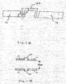
- FIG. 1is a perspective elevated view of an exemplary coupling member used to convert a two-post equipment rack to support four-post equipment;
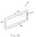
- FIGS. 2A and 2Eare perspective elevated views of the coupling member of FIG. 1 in alternate embodiments;
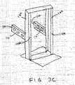
- FIG. 3Ais an exemplary perspective installation sequence for converting a two-post equipment rack including the coupling member of FIG. 1 and/or FIG. 2 to support four-post equipment;
- FIG. 3Bis an exemplary perspective view of a converted two-post equipment rack in a different configuration from FIG. 3A;
- FIG. 3Cis an exemplary perspective view of a converted two-post equipment rack in a different configuration from FIG. 3A;
- FIG. 4is an exemplary schematic flow chart depicting steps for converting a two-post equipment rack including the coupling member of FIG. 1 and/or FIG. 2 to support four-post equipment;
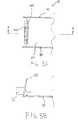
- FIG. 5Ais an exemplary top plan view of the rack attachment flange of the coupling member of FIG. 1;
- FIG. 5Bis a cross-section of FIG. 5A taken along line A-A;
- FIG. 6is an exemplary perspective view of a converted two-post equipment rack having the coupling members of FIG. 1 and/or FIG. 2 secured thereto and supporting a load thereon;
- FIG. 7Ais an exemplary perspective front side view of a two-post rack
- FIG. 7Bis an exemplary side view of a load coupled to a two-post rack utilizing coupling members in accordance with the principles of the present invention
- FIGS. 8 A- 8 Eare side views of exemplary embodiments according to the principles of the present invention.
- FIG. 9is an exemplary perspective side view of two coupling members in a supporting configuration
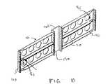
- FIG. 10is an exemplary perspective side view of two coupling members coupled together
- FIGS. 11A and 11Bare top plan views of the coupling member showing the angle between a surface of a post and the coupling member;
- FIG. 12is an exemplary side view of four coupling members secured to a post.
- FIG. 13is an exemplary flow chart for providing a two- to four-post adapter according to the principles of the present invention.
- the present inventionprovides a solution to this dilemma.
- Several coupling membersare provided herein which efficiently and economically secure to two-post racks and emulate four-post equipment racks, allowing four-post equipment to be stored thereon.
- the present inventionmay provide a convenient coupling feature between the coupling members, allowing heavier loads to be stored thereon.
- the present inventionfurther provides a modular system for adapting the two-post racks, such that a user of the present invention can direct the placement of the coupling members.
- only the necessary number of coupling members in only the necessary locationsmay be utilized, thereby minimizing the number of brackets used to only those required for structural support.
- four-post rack loadrefers to equipment or hardware that is commonly mounted in a four-post cabinet or rack.
- Computers, servers, disk arrays and other electronic devicesare a few examples of equipment.
- Sliding rails, shelves, monitor stands and other mechanical structuresare a few examples of hardware that can be supported by the present invention.
- Most common four-post mounting equipment and hardwareis designed to meet the EIA-310 standard, although other standards and variations exist.
- FIG. 1there is shown a perspective view of a coupling member 10 for converting a two-post equipment rack system to a four-post rack system.
- the coupling member 10includes a vertical support member 20 having a first lateral end 30 , a second lateral end 40 , a first longitudinal end 50 , and a second longitudinal end 60 .
- a first torsion member 70is coupled to the vertical support member 20 at the first longitudinal end 50 .
- a second torsion member 80is coupled to the vertical support member 20 at the second longitudinal end 60 .
- First and second torsion member 70 , 80generally reduce deflection and buckling of the coupling member 10 .
- adapter or converterand the respective derivatives refer to any structure capable of providing two- to four-post load support properties.
- FIG. 7Athere is shown an exemplary side perspective view of a two-post rack 801 .
- the two post rack 810also referred to as a telco rack and a relay rack, historically has been used for telephony equipment, relays, and patch panels.
- the two-post rack 801consists of two vertical uprights 160 , or posts, used for attaching equipment. These posts 160 are typically “C” shaped and have mounting features 800 on the front and rear of both posts 160 .
- Two-post racks 801typically have an overall depth of 2′′ to 10′′ from front mounting surface to back mounting surface. Functionally, a two-post rack 801 is very similar to a four-post rack, aside from being shallow in depth.
- the holes of the mounting features 800typically conform to the guidelines of the EIA-310 specification.
- Two-post racks 801usually have a means of attaching the rack to the floor for stability, shown by the base 810 .
- the hole pattern on the front and back 800 of the two posts 160typically conform to the EIA-310 standard.
- the standardspecifies the vertical hole spacing and the right post to left post hole spacing. This standard also describes a minimum opening between the right and left posts 160 .
- FIG. 7Bthere is shown an exemplary perspective side view of a four-post rack 820 .
- Four-post racks 820are often referred to as an equipment or cabinet rack.
- the four-post rack's chief featureis the provision of four vertical uprights 830 , 840 , 850 , 860 , or posts, used for attaching equipment.
- the four-post rackmay or may not have side panels 890 , front doors 880 , and rear doors (not shown), top and bottom panels, and other features.
- Four-post racks 820typically have an overall depth of 16′′ to 34′′ from a front post to a back post.
- Four-post racks 820typically abide by the guidelines of the EIA-310 specification.
- the shape of the postsvary, however they all include mounting features 870 on the four posts facing front and back.
- the poststypically conform to the EIA-310 standard.
- the standardspecifies the vertical hole spacing and the right post to left post hole spacing. This standard also describes a minimum opening 900 between the right and left posts
- a coupling feature 90is provided on the first torsion member 70 and the second torsion member 80 .
- the coupling featureis used to couple the coupling member 10 to adjacent coupling members (not shown in FIG. 1), thereby increasing the load supporting capability of the coupling member 10 .
- the coupling feature 90is an orifice through which a fastener, such as a screw and the like, may be used to secure the adjacent coupling members.
- the placement of the coupling feature 90is exemplary in FIG. 1, and other locations and fasteners for the coupling member are contemplated to be within the scope of the present invention.
- FIG. 9there is shown coupling members 10 adjacent to one another.
- the height X of the equipment attachment flange 120is tightly controlled, such that the coupling members 10 may be stacked upon one another, and in this embodiment, the top coupling member benefits from the support received through the equipment attachment flange 120 to the bottom coupling member 10 .
- the coupling member 10is formed in increments of one “U” in height.
- FIG. 10there is a more detailed showing of the coupling feature 90 as described above.
- both coupling members 10are supported equally due to the coupling thereof
- Both coupling members on either side of the post 160are secured to one another via a fastener 91 through the coupling feature 90 .
- first torsion member 70 and second torsion member 80each have a upper and lower flange ends 101 adapted to mate with the two-post rack.
- the lower flange end 101also provides a pivot point for load support.
- the lower flange end 101adds structural stability to loads supported by the coupling member 10 , but is not required to adapt a two-post equipment rack to a four-post equipment rack.
- the angle BETAcompensates for the non-square mounting surface ALPHA found on two post racks.
- the non-square mounting surface ALPHAtypically results from distortion in the posts due to cooling after extrusion of the posts.
- the obtuse angle on torsion members 70 , 80ensures that the coupling member are at least square and conform with EIA-310. This assists in the loading of four post rack loads into the racks by maintaining a proper opening 900 .
- the upper and lower flange ends 100terminate prior to the first lateral end 30 , creating a gap.
- This gap behind the flange 110provides space for the attachment of loads that may extend above or below the height of the coupling member. It is contemplated that the first and second torsion members 70 and 80 extend entirely to the first lateral end 30 .
- an equipment attachment flange 110may be coupled to the first lateral end 30 .
- the equipment attachment flange 110is intended to support loads.
- the equipment attachment flange 110may be adapted to emulate a vertical upright in a common four-post rack (not shown) or to emulate the characteristics of a specific vendors rack, including attachment feature size and attachment feature location.
- a sliding rail(not shown) may be attached to the coupling member 10 to slide equipment mounted on the coupling member laterally.
- the term “to emulate”means to imitate the function of The equipment attachment flange 110 , therefore, may be adapted to receive a sliding rail.
- the equipment attachment flange 110may define a supporting point for a load.
- the equipment attachment flange 110includes one or more orifices 120 for securing to various pieces of equipment.
- the orifices 120may be adapted to emulate orifices found in four-post equipment racks. It is contemplated that the number, placement, size and configuration of the orifices 120 may vary, and may include a modular design. Such a design would allow for the creation of one orifice 120 that may be adapted to receive several connection points from equipment.
- the equipment attachment flange 110is of a predetermined thickness, which may be adjusted depending on the requirements of the system. In certain preferred embodiments, the equipment attachment flange is substantially perpendicular to the vertical support member 20 . However, in some embodiments the angle between the vertical support member 20 and the equipment attachment flange may be acute or obtuse.
- a means for securing the coupling member 10 to a two-post equipment racksuch as a rack attachment flange 130 may be coupled to the second lateral end 40 .
- the rack attachment flange 130may be adapted to provide a load transfer path from the vertical support member 20 to the two-post equipment rack (not shown in FIG. 1).
- the rack attachment flange 130may include at least one rack connection point 140 .
- the rack attachment point 140is an orifice adapted to mate with a like orifice from a two-post equipment rack.
- the rack attachment flange 130may run the span of the second lateral end 40 , or as is shown in FIG. 1, there may be a gap between the first torsion member 70 , the rack attachment flange 130 , and the second torsion member 80 .
- a greater description of the rack attachment flange 130is provided below in reference to FIGS. 5A and 5B.
- first torsion member 70 and the second torsion member 80are coupled substantially perpendicular to the vertical support member 20 .
- the thickness of the first torsion member 70 and second torsion member 80may vary depending on the requirements of the system. In some embodiments utilizing more than one coupling member 10 , it is advantageous to maintain the coupling members 10 independent of one another to not obstruct openings formed in the racks and to conform with EIA-310. The independence of these members 10 may be determined by the user based on the application.
- the coupling member 10may be provided with one or more openings 150 .
- the openings 150may be utilized for air ventilation, weight reduction and aesthetics, among other reasons.
- the openings 150may further be used as cable tie points, wherein equipment stored in the coupling member 10 may have cables extending therefrom. These cables may be secured to the coupling member 10 with tie wraps and the like at the openings 150 . It is appreciated that the openings 150 are not integral to the load supporting function of the coupling member 10 , but in certain instances may act as an aid in the load transfer through the coupling member 10 .
- FIG. 2Athere is shown a perspective view of a coupling member 10 A in an alternate embodiment, with like numerals being designated for like parts.
- This embodimentis similar to coupling member 10 of FIG. 1.
- the vertical support member 20 Ais not provided with any openings.
- This embodimentsupports loads in a similar fashion as the coupling member 10 of FIG. 1.
- the thickness of the vertical support member 20 A, and the flanges 130 A, 140 Amay be adjusted to compensate for the loss of the first torsion member 70 and the second torsion member 80 in the embodiment of FIG. 1.
- the height Z of the flange 130 Amay be adjusted to compensate for the loss of the lower flange end adapted to act as a pivot point in the embodiment of FIG. 1.
- FIG. 2Bthere is shown a perspective view of a coupling member 10 B in an alternate embodiment, with like numerals being designated for like parts.
- This embodimentis similar to coupling member 10 of FIG. 1.
- first torsion member 70 A and second torsion member 80 Bextend to the equipment attachment flange 120 A and to the rack attachment flange 130 B.
- the vertical support member 20 Bis not provided with any openings. This embodiment supports loads in a similar fashion as the coupling member 10 of FIG. 1.
- coupling member 10 Cincludes rack attachment flange 130 C coupled to the vertical support member 20 C.
- rack attachment flange 130 Ccoupled to the vertical support member 20 C.
- a plurality of holes 120 Care provided on the vertical support member 20 C for securement to a flange and the like (not shown).
- the holes 90 Cwhich are similar in location to the plurality of holes 120 C, may be used for coupling the coupling member 10 C to adjacent coupling members (not shown).
- FIG. 2Dshows a coupling member 10 D having an equipment attachment flange 110 D secured to the vertical support member 20 D via the openings 95 D.
- the holes 90 Dmay be used for coupling the coupling member 20 D to adjacent coupling members (not shown).
- FIG. 2Eis yet another embodiment of a two coupling members 10 E.
- This embodimentprovides one equipment attachment flange 110 E coupling more than one coupling members 10 E to one another while also allowing coupling of the coupling members 10 E to equipment (not shown).
- the equipment attachment flange 110 Eis modular, and may be placed on holes 90 E.
- FIGS. 5A and 5Bthere is shown a top plan view of the rack attachment flange 130 of the coupling member 10 and a cross-section view of the rack attachment flange 130 taken along line A-A, respectively.
- the torsion members 70 , 80extend beyond the rack attachment flange 130 .
- the rack attachment flange 130is also bent at an acute angle, ⁇ , such that when the rack attachment flange 130 is secured to a two-post equipment rack (not shown in FIGS.
- a spring-effectresults from the contact of the torsion members 70 , 80 to the two-post equipment rack and the coupling of the rack attachment flange 130 to the two-post equipment rack. This has the effect of pre-loading the coupling member 10 , such that when a load is applied, the deflection of the coupling member 10 is minimized.
- ⁇may be as little as several tenths of a degree or as great as several degrees.
- the exact calculation of the angle ⁇may be determined through calculation of the desired loading, and may therefore vary from application to application. It is recognized that although the pre-loading configuration of the rack attachment flange 130 is preferred, the rack attachment flange 130 may be in a substantially perpendicular or perpendicular relationship with the vertical support member 20 of the coupling member 10 .
- FIG. 12there is shown a side view of four coupling members 10 secured to a post 160 having a load, in this case a slide assembly 170 , attached thereto. From this view, it is apparent that other loads, such as equipment and the like, may be secured to the coupling members 10 via the equipment flanges 110 . Although not shown, in this configuration the coupling members 10 may be secured to one another via coupling features 90 located on torsion members 70 , 80 of the coupling member 10 . This configuration is adapted to support loads that may exceed the load-bearing capacity of two coupling members 10 .
- Other slide assemblies 160conventional in the art may be adapted to as few as one coupling member 10 , depending on the requirements of the application.
- slide assemblies 170may be specifically designed to adapt to coupling members 10 , although such design may not be necessary, given the design of the coupling member 10 . It is further contemplated that some slide assemblies 170 may be specifically designed to adapt to the vertical support member 20 , and thus eliminate the need for the equipment attachment flange 110 .
- the slide assembly 170secures to the equipment attachment flange 110 via one or more of the orifices 120 (FIG. 1) through connectors 180 on the slide assembly. Because the coupling members 10 are provided with one or more orifices 20 , the number and types of connections between the load and the equipment attachment flange 110 may vary, such connection means being contemplated as within the scope of this invention.
- connection between the slide assembly 170 and the coupling member 10does not affect the securement of additional loads, such as equipment and the like, to the coupling member 10 .
- a slide assembly 170may not be required, as some applications currently do not require the use of a slide assembly 170 .
- FIG. 6there is shown a perspective view of a converted two-post equipment rack having the coupling members 10 , 10 A secured thereto and supporting loads 190 A, 190 B thereon.
- slide assembly 170is mounted on the coupling member 10 and the first load 190 A secured to the slide assembly 170 .
- an adjacent additional coupling member 10 Ais coupled thereto to provide increased load support.
- the load 190 Atravels on one side of the posts 160 , only one coupling member 10 is needed on the opposite side of the post 160 .
- load 190 Bis secured to a coupling member 10 without the use of slide assembly 170 .
- the load 190 Bspans both sides of the post 160 .
- cables 195 extending from load 190 Bcan be secured to the openings 150 of the coupling member 10 via tie-wraps and the like (not specifically shown).
- the coupling member 10 Amay alternately be used to support the loads 190 A, 190 B, should such be desired.
- the coupling membersmay be arranged in any number of configurations depending on the load being supported and the requirements of the system. Such configuration is left to discretion, with such configurations considered to be within the scope of the present invention.
- Coupling member 10is preferably made of metal, and is preferably made in a process whereby a sheet of metal is first placed in a stamping machine as understood in the art. The requisite parts of the metal are stamped in one or more steps and separated from the remaining portion of the sheet. Next the perforated metal is delivered to a crimping device, which bends the torsion members, the equipment attachment flange, and the rack attachment flange to their predetermined angles. In some embodiments, the rack attachment flange is bent at an acute angle relative to the vertical support member in order to place the coupling member in a pre-loading configuration.
- the bent metal sheetmay then be subjected to an anti-corrosive process, such as by painting the coupling member, and may be imprinted with textual and numerical script.
- an anti-corrosive processsuch as by painting the coupling member, and may be imprinted with textual and numerical script.
- Other processessuch as progressive die stamping and casting the coupling member from a pre-fabricated cast, are contemplated to be within the scope of the present invention.
- other non-metal materialsmay be utilized to form the coupling member 10 .
- FIGS. 3A and 3Bthere is shown a perspective exemplary installation sequence for converting a two-post equipment rack to support four-post equipment, and an exemplary configuration of a converted two-post equipment rack.
- a two-post equipment rack 200 having a first post 160 A and a second post 160 Bis first provided, designated by AA.
- a first coupling member 10 Cis coupled to a first side of post 160 A, as designated by BB.
- a second coupling member 10 Dis coupled to a second side of the post 160 B substantially planar to and substantially parallel to the first coupling member 10 C, designated by CC.
- a third and fourth coupling member 10 E, 10 Fare secured on a first side and a second side of a second post 160 B, as designated by EE and FF.
- EE and FFthe user has now coupled independent four-post replicating mounting points on the two-post rack 200 .
- a slide assembly 170may then be attached to the inside-facing sides of the coupling members 10 C, 10 D, 10 E and 10 F.
- the four-post emulated mounting pointsnow can support four-post loads such as slide assembly 170 or other loads 190 , as shown by FF and GG.
- a load 190as such as equipment, may then be secured to the slide assembly 170 . In this case, the load is transferred through the slide assembly 170 to the coupling members 10 C, 10 D, 10 E and 10 F. It is contemplated that some loads do not require slide assemblies.
- a load 190such as equipment not needing slide assemblies, may then be directly secured to the coupling member 10 C, 10 D, 10 E and 10 F as required, designated by GG. More coupling members 10 may be secured to the posts 160 A, 160 B as required and more loads 190 may be secured thereto, designated by HH.
- the coupling members 10may be secured in a manner as determined by the requirements of the load, as shown in the exemplary configuration of FIG. 3B.
- Each coupling member 10may be coupled the adjacent coupling member 10 using a the coupling feature 90 shown in FIG. 1, thereby increasing the load capacity and structural integrity of each coupling member 10 .
- FIG. 3Can exemplary embodiment is shown having two equipment attachment flanges 110 , and two attachment points 110 A provided on the posts 160 .
- This structurenow forms an equivalent four-post rack. It can be seen from FIG. 3C that a load would not be centered. But a load in FIG. 3A would be substantially centered. Centering of the loads would have the added advantage of balancing loads in the rack, but in some circumstances, such as when spacing requirements are confined, it may not be possible to center the load.
- FIG. 4there is shown a schematic exemplary installation flow chart for converting a two-post equipment rack to support four-post equipment.
- a first coupling membermay be coupled to a first side of a first post of a two-post equipment rack, as shown by box 400 .
- a second, third and fourth coupling membermay be coupled to the respective sides of the respective posts, shown in boxes 400 , 500 and 600 .
- a loadmay be coupled to at least one coupling member, as shown in box 700 .
- Other installation sequences varying the connection orderare contemplated to be within the scope of the principles of the present invention.
- FIGS. 8 A-Ethere is shown an exemplary side view of a load 1103 coupled to a two-post rack utilizing coupling members in accordance with the principles of the present invention.
- a post 1101 of a two-post equipment rackis shown.
- Two coupling members 1102are provided outward from the post 1101 .
- the coupling members 1102may be coupled to the post 1101 in any configuration, inasmuch as the coupling members 1102 are sufficiently secured to the post 1101 so that the coupling members 1102 may support a load 1103 .
- a load 1103is secured to the coupling members 1102 and supported thereby.
- the structure of the coupling members 1102may vary, depending on the requirements of the system.
- the coupling members 1102may have angled connection points to the post 1101 .
- examples of coupling membersare shown in various configurations. As can be seen, these coupling members all function to support a load while replicating a four-post equipment rack, such that four-post equipment may be placed thereon.
- the coupling member 02may be one integral member that provides contact points 1105 on one or either side of the post 1101 .
- At least one commercially-available rackhas a front-to-back-post depth of about 28.875′′. It can be appreciated that the present invention can provide a plurality of coupling members on such a rack or other commercially-available racks and, through placement of the coupling members, adjust the forward and/or aft depth to match the intended commercially-available rack. Further adjustments to the coupling members, including conversion of the mounting features, are contemplated to be within the scope of the present invention.
- the advantage of replicating a specific commercially-available rack made by vendor Wis the loads made by the rack-equipment manufacturer W to fit in W racks will also fit in the emulated rack, thereby eliminating costly unnecessary equipment modifications. Such replicating devices can function as an equipment support device, depending on the application.
- FIG. 13is an exemplary flow chart for providing a two- to four-post adapter according to the principles of the present invention.
- features of the present inventionare accomplished by installing a two-post to for-post adapter on a two-post rack, shown by box 1300 .
- a devicemay be mounted to the adapter, shown by box 1310 .
- the adaptermay be coupled to the two-post rack, shown by box 1320 .
- the present inventionprovides for a method for enabling the rack mounting of a device having a four-post rack-mounting configuration to a two-post rack system by providing a two-post to four-post adapter on a two-post rack system.
- Such two-post to four-post adapteris preferably operable to support a device, including slide assemblies and electronic devices such as computer servers, having a four-post rack-mounting configuration.
- the two-post to four-post adaptermay include at least two coupling members.
- steps that may be taken in accordance with the principles of the present inventioninclude measuring hardware that has a four-post rack-mounting configuration to provide for the configuration of the device and specifying dimensions for the two-post to four-post adapter based on this measuring. Additional steps may include selling, distributing, including, offering for sale, advertising, and marketing the apparatus and method disclosed herein. Some two-post to four-post adapters may be provided with the two-post rack system. Some two-post to four-post adapters may alternately be provided with the four-post rack mount equipment.
Landscapes
- Engineering & Computer Science (AREA)
- Microelectronics & Electronic Packaging (AREA)
- Cooling Or The Like Of Electrical Apparatus (AREA)
- Casings For Electric Apparatus (AREA)
- Assembled Shelves (AREA)
Abstract
Description
- 1. Field of the Invention[0001]
- The present invention generally relates to a support rack, and more specifically but not by way of limitation, to an apparatus and method for supporting four-post rack mounted equipment in a two-post equipment rack system.[0002]
- 2. Background[0003]
- Equipment racks are used to support many different types of equipment or systems (e.g., computer servers). Many equipment manufacturers provide equipment with support mechanisms for being supported in traditional four-post rack systems (e.g., cabinets). Often, four-post racks, such as those shown in (Electronic Industries Association) EIA Standard EIA-310-D, incorporated herein by reference, can cost thousands of dollars while two-post equipment racks may only cost several hundred dollars. Therefore, users of four-post rack mountable equipment are interested in an economical, easy alternative to having to use four-post rack systems.[0004]
- In today's ever-increasing technological world, many equipment systems are becoming smaller and smaller. However, there remain many systems that are still relatively large. As many modern corporations utilize these systems, it is generally desirable and economical to store these systems in one convenient location, which traditionally has been a four-post rack. These racks must be designed to handle the heavy and light loads of the different systems stored therein.[0005]
- While a four-post rack traditionally has been the standard for users to mount these systems, due to the expense associated with the four-post racks, two-post equipment racks have been increasingly desirable. The two-post equipment racks provide the benefit of allowing equipment mounted thereto to be more accessible to a user. The two-post rack further takes up less real estate than full four-post rack systems. However, because most equipment systems are pre-designed for four-post racks, the user has been subjected to having to purchase expensive four-post equipment racks to mount the equipment.[0006]
- To overcome the problems of having to mount equipment systems having pre-designed four-post attachments, the principles of the present invention provide for an apparatus and method for adapting two-post rack systems to support four-post rack mounted equipment. In one embodiment, the apparatus includes a coupling member for modifying a two-post equipment rack. The coupling member may include a vertical support member having a first and second lateral end, and a first and second longitudinal end. A first torsion member may be coupled to the vertical support member at the first longitudinal end, and a second torsion member may be coupled to the vertical support member at the second longitudinal end. A coupling feature on the torsion members may be included to allow coupling to adjacent coupling members. An equipment attachment flange may be coupled to the first lateral end, and may further be adapted to emulate a vertical upright in a four-post rack. A rack attachment flange may be coupled to the second lateral end, and may be adapted to provide a load transfer path from the vertical support member to the two-post equipment rack. A lower flange end may be provided on the first and second torsion member, and may be adapted to provide a pivot point for load support.[0007]
- One embodiment of a method for converting a two-post equipment rack may include a user first securing a first-load supporting member to a first post. The step may be repeated such that each post has two load-supporting members secured thereto, thereby replicating a four-post rack. A load, including a slide-rail and the like, may then be coupled to the load-supporting members. In certain embodiments, the load-supporting members may be secured to adjacent load supporting members to increase the load bearing strength of the load-supporting members.[0008]
- These and other features, aspects, and advantages of the present invention will become better understood with regard to the following description, appended claims, accompanying drawings where:[0009]
- FIG. 1 is a perspective elevated view of an exemplary coupling member used to convert a two-post equipment rack to support four-post equipment;[0010]
- FIGS. 2A and 2E are perspective elevated views of the coupling member of FIG. 1 in alternate embodiments;[0011]
- FIG. 3A is an exemplary perspective installation sequence for converting a two-post equipment rack including the coupling member of FIG. 1 and/or FIG. 2 to support four-post equipment;[0012]
- FIG. 3B is an exemplary perspective view of a converted two-post equipment rack in a different configuration from FIG. 3A;[0013]
- FIG. 3C is an exemplary perspective view of a converted two-post equipment rack in a different configuration from FIG. 3A;[0014]
- FIG. 4 is an exemplary schematic flow chart depicting steps for converting a two-post equipment rack including the coupling member of FIG. 1 and/or FIG. 2 to support four-post equipment;[0015]
- FIG. 5A is an exemplary top plan view of the rack attachment flange of the coupling member of FIG. 1;[0016]
- FIG. 5B is a cross-section of FIG. 5A taken along line A-A;[0017]
- FIG. 6 is an exemplary perspective view of a converted two-post equipment rack having the coupling members of FIG. 1 and/or FIG. 2 secured thereto and supporting a load thereon;[0018]
- FIG. 7A is an exemplary perspective front side view of a two-post rack;[0019]
- FIG. 7B is an exemplary side view of a load coupled to a two-post rack utilizing coupling members in accordance with the principles of the present invention;[0020]
- FIGS.[0021]8A-8E are side views of exemplary embodiments according to the principles of the present invention;
- FIG. 9 is an exemplary perspective side view of two coupling members in a supporting configuration;[0022]
- FIG. 10 is an exemplary perspective side view of two coupling members coupled together;[0023]
- FIGS. 11A and 11B are top plan views of the coupling member showing the angle between a surface of a post and the coupling member;[0024]
- FIG. 12 is an exemplary side view of four coupling members secured to a post; and[0025]
- FIG. 13 is an exemplary flow chart for providing a two- to four-post adapter according to the principles of the present invention.[0026]
- Current typical rack equipment storage devices, such as four-post racks, are very costly and space-consuming. However, despite the availability of less-expensive two-post equipment racks, there has not been available any means of attaching four-post equipment to two-post racks.[0027]
- The present invention provides a solution to this dilemma. Several coupling members are provided herein which efficiently and economically secure to two-post racks and emulate four-post equipment racks, allowing four-post equipment to be stored thereon. In addition, the present invention may provide a convenient coupling feature between the coupling members, allowing heavier loads to be stored thereon. The present invention further provides a modular system for adapting the two-post racks, such that a user of the present invention can direct the placement of the coupling members. In addition, only the necessary number of coupling members in only the necessary locations may be utilized, thereby minimizing the number of brackets used to only those required for structural support.[0028]
- The term “four-post rack load” or “load” as used herein refers to equipment or hardware that is commonly mounted in a four-post cabinet or rack. Computers, servers, disk arrays and other electronic devices are a few examples of equipment. Sliding rails, shelves, monitor stands and other mechanical structures are a few examples of hardware that can be supported by the present invention. Most common four-post mounting equipment and hardware is designed to meet the EIA-310 standard, although other standards and variations exist.[0029]
- Referring first to FIG. 1, there is shown a perspective view of a[0030]
coupling member 10 for converting a two-post equipment rack system to a four-post rack system. Thecoupling member 10 includes avertical support member 20 having a firstlateral end 30, a second lateral end40, a firstlongitudinal end 50, and a secondlongitudinal end 60. Afirst torsion member 70 is coupled to thevertical support member 20 at the firstlongitudinal end 50. Asecond torsion member 80 is coupled to thevertical support member 20 at the secondlongitudinal end 60. First andsecond torsion member coupling member 10. - As used herein, the terms adapter or converter and the respective derivatives refer to any structure capable of providing two- to four-post load support properties.[0031]
- Referring now to FIG. 7A, there is shown an exemplary side perspective view of a two-post rack[0032]801. The two
post rack 810, also referred to as a telco rack and a relay rack, historically has been used for telephony equipment, relays, and patch panels. The two-post rack801 consists of twovertical uprights 160, or posts, used for attaching equipment. Theseposts 160 are typically “C” shaped and have mountingfeatures 800 on the front and rear of bothposts 160. Two-post racks801 typically have an overall depth of 2″ to 10″ from front mounting surface to back mounting surface. Functionally, a two-post rack801 is very similar to a four-post rack, aside from being shallow in depth. The holes of the mounting features800 typically conform to the guidelines of the EIA-310 specification. Two-post racks801 usually have a means of attaching the rack to the floor for stability, shown by thebase 810. The hole pattern on the front and back800 of the twoposts 160 typically conform to the EIA-310 standard. The standard specifies the vertical hole spacing and the right post to left post hole spacing. This standard also describes a minimum opening between the right and leftposts 160. - Referring now to FIG. 7B, there is shown an exemplary perspective side view of a four-post rack[0033]820. Four-post racks820 are often referred to as an equipment or cabinet rack. The four-post rack's chief feature is the provision of four
vertical uprights side panels 890, front doors880, and rear doors (not shown), top and bottom panels, and other features. Four-post racks820 typically have an overall depth of 16″ to 34″ from a front post to a back post. Four-post racks820 typically abide by the guidelines of the EIA-310 specification. The shape of the posts vary, however they all include mountingfeatures 870 on the four posts facing front and back. The posts typically conform to the EIA-310 standard. The standard specifies the vertical hole spacing and the right post to left post hole spacing. This standard also describes aminimum opening 900 between the right and left posts - Referring back to FIG. 1, a[0034]
coupling feature 90 is provided on thefirst torsion member 70 and thesecond torsion member 80. The coupling feature is used to couple thecoupling member 10 to adjacent coupling members (not shown in FIG. 1), thereby increasing the load supporting capability of thecoupling member 10. As shown in this embodiment, thecoupling feature 90 is an orifice through which a fastener, such as a screw and the like, may be used to secure the adjacent coupling members. The placement of thecoupling feature 90 is exemplary in FIG. 1, and other locations and fasteners for the coupling member are contemplated to be within the scope of the present invention. - Referring now to FIG. 9, there is shown coupling[0035]
members 10 adjacent to one another. In this exemplary configuration, the height X of theequipment attachment flange 120 is tightly controlled, such that thecoupling members 10 may be stacked upon one another, and in this embodiment, the top coupling member benefits from the support received through theequipment attachment flange 120 to thebottom coupling member 10. There are certain advantages to making height X an even increment of “U”, which may be defined as the modular unit on which panel heights are based, and is typically about 1.75″. These include modularity advantages, because most loads are built based in increments of “U”, and conservation of available “U” space is considered premium. In preferred embodiments, thecoupling member 10 is formed in increments of one “U” in height. - Referring now to FIG. 10, there is a more detailed showing of the[0036]
coupling feature 90 as described above. As can be seen in this embodiment, bothcoupling members 10 are supported equally due to the coupling thereof Both coupling members on either side of thepost 160 are secured to one another via a fastener91 through thecoupling feature 90. - Referring back to FIG. 1, in this embodiment the[0037]
first torsion member 70 andsecond torsion member 80 each have a upper and lower flange ends101 adapted to mate with the two-post rack. Thelower flange end 101 also provides a pivot point for load support. Thelower flange end 101 adds structural stability to loads supported by thecoupling member 10, but is not required to adapt a two-post equipment rack to a four-post equipment rack. - Referring now to FIGS. 11A and 11B, the angle-correction characteristics are shown in greater detail. As can be seen by the surface of the[0038]
coupling member 10, the angle BETA compensates for the non-square mounting surface ALPHA found on two post racks. The non-square mounting surface ALPHA typically results from distortion in the posts due to cooling after extrusion of the posts. The obtuse angle ontorsion members proper opening 900. - Referring back to FIG. 1, in this embodiment the upper and lower flange ends[0039]100 terminate prior to the first
lateral end 30, creating a gap. This gap behind theflange 110 provides space for the attachment of loads that may extend above or below the height of the coupling member. It is contemplated that the first andsecond torsion members lateral end 30. - Still referring to FIG. 1, an[0040]
equipment attachment flange 110 may be coupled to the firstlateral end 30. Theequipment attachment flange 110 is intended to support loads. Theequipment attachment flange 110 may be adapted to emulate a vertical upright in a common four-post rack (not shown) or to emulate the characteristics of a specific vendors rack, including attachment feature size and attachment feature location. In an alternative embodiment, a sliding rail (not shown) may be attached to thecoupling member 10 to slide equipment mounted on the coupling member laterally. As used herein, the term “to emulate” means to imitate the function of Theequipment attachment flange 110, therefore, may be adapted to receive a sliding rail. Theequipment attachment flange 110 may define a supporting point for a load. In addition, theequipment attachment flange 110 includes one ormore orifices 120 for securing to various pieces of equipment. Theorifices 120 may be adapted to emulate orifices found in four-post equipment racks. It is contemplated that the number, placement, size and configuration of theorifices 120 may vary, and may include a modular design. Such a design would allow for the creation of oneorifice 120 that may be adapted to receive several connection points from equipment. Theequipment attachment flange 110 is of a predetermined thickness, which may be adjusted depending on the requirements of the system. In certain preferred embodiments, the equipment attachment flange is substantially perpendicular to thevertical support member 20. However, in some embodiments the angle between thevertical support member 20 and the equipment attachment flange may be acute or obtuse. - Still referring to FIG. 1, a means for securing the[0041]
coupling member 10 to a two-post equipment rack such as arack attachment flange 130 may be coupled to the second lateral end40. Therack attachment flange 130 may be adapted to provide a load transfer path from thevertical support member 20 to the two-post equipment rack (not shown in FIG. 1). Therack attachment flange 130 may include at least onerack connection point 140. In this embodiment, therack attachment point 140 is an orifice adapted to mate with a like orifice from a two-post equipment rack. Therack attachment flange 130 may run the span of the second lateral end40, or as is shown in FIG. 1, there may be a gap between thefirst torsion member 70, therack attachment flange 130, and thesecond torsion member 80. A greater description of therack attachment flange 130 is provided below in reference to FIGS. 5A and 5B. - Still referring to FIG. 1, although not required, it is preferred that the[0042]
first torsion member 70 and thesecond torsion member 80 are coupled substantially perpendicular to thevertical support member 20. The thickness of thefirst torsion member 70 andsecond torsion member 80 may vary depending on the requirements of the system. In some embodiments utilizing more than onecoupling member 10, it is advantageous to maintain thecoupling members 10 independent of one another to not obstruct openings formed in the racks and to conform with EIA-310. The independence of thesemembers 10 may be determined by the user based on the application. - As shown in FIG. 1, the[0043]
coupling member 10 may be provided with one ormore openings 150. Theopenings 150 may be utilized for air ventilation, weight reduction and aesthetics, among other reasons. Theopenings 150 may further be used as cable tie points, wherein equipment stored in thecoupling member 10 may have cables extending therefrom. These cables may be secured to thecoupling member 10 with tie wraps and the like at theopenings 150. It is appreciated that theopenings 150 are not integral to the load supporting function of thecoupling member 10, but in certain instances may act as an aid in the load transfer through thecoupling member 10. - Referring now to FIG. 2A, there is shown a perspective view of a coupling member[0044]10A in an alternate embodiment, with like numerals being designated for like parts. This embodiment is similar to
coupling member 10 of FIG. 1. In this embodiment, the vertical support member20A is not provided with any openings. This embodiment supports loads in a similar fashion as thecoupling member 10 of FIG. 1. The thickness of the vertical support member20A, and theflanges 130A,140A may be adjusted to compensate for the loss of thefirst torsion member 70 and thesecond torsion member 80 in the embodiment of FIG. 1. The height Z of theflange 130A may be adjusted to compensate for the loss of the lower flange end adapted to act as a pivot point in the embodiment of FIG. 1. - Referring now to FIG. 2B, there is shown a perspective view of a coupling member[0045]10B in an alternate embodiment, with like numerals being designated for like parts. This embodiment is similar to
coupling member 10 of FIG. 1. In this embodiment, first torsion member70A and second torsion member80B extend to the equipment attachment flange120A and to the rack attachment flange130B. In addition, the vertical support member20B is not provided with any openings. This embodiment supports loads in a similar fashion as thecoupling member 10 of FIG. 1. - Referring not to FIGS.[0046]2C-2E, there is shown yet other embodiments of the
coupling member 10C,10D, and10E. In FIG. 2C, coupling member10C includesrack attachment flange 130C coupled to the vertical support member20C. However, instead of an equipment attachment flange, a plurality of holes120C are provided on the vertical support member20C for securement to a flange and the like (not shown). The holes90C, which are similar in location to the plurality of holes120C, may be used for coupling the coupling member10C to adjacent coupling members (not shown). - FIG. 2D shows a coupling member[0047]10D having an
equipment attachment flange 110D secured to the vertical support member20D via the openings95D. The holes90D may be used for coupling the coupling member20D to adjacent coupling members (not shown). - FIG. 2E is yet another embodiment of a two[0048]
coupling members 10E. This embodiment provides one equipment attachment flange110E coupling more than onecoupling members 10E to one another while also allowing coupling of thecoupling members 10E to equipment (not shown). The equipment attachment flange110E is modular, and may be placed on holes90E. - Referring now to FIGS. 5A and 5B, there is shown a top plan view of the[0049]
rack attachment flange 130 of thecoupling member 10 and a cross-section view of therack attachment flange 130 taken along line A-A, respectively. In this embodiment of therack attachment flange 130, thetorsion members rack attachment flange 130. Therack attachment flange 130 is also bent at an acute angle, Δ, such that when therack attachment flange 130 is secured to a two-post equipment rack (not shown in FIGS. 5A, 5B), a spring-effect results from the contact of thetorsion members rack attachment flange 130 to the two-post equipment rack. This has the effect of pre-loading thecoupling member 10, such that when a load is applied, the deflection of thecoupling member 10 is minimized. - In some embodiments, Δ may be as little as several tenths of a degree or as great as several degrees. The exact calculation of the angle Δ may be determined through calculation of the desired loading, and may therefore vary from application to application. It is recognized that although the pre-loading configuration of the[0050]
rack attachment flange 130 is preferred, therack attachment flange 130 may be in a substantially perpendicular or perpendicular relationship with thevertical support member 20 of thecoupling member 10. - Referring now to FIG. 12, there is shown a side view of four[0051]
coupling members 10 secured to apost 160 having a load, in this case aslide assembly 170, attached thereto. From this view, it is apparent that other loads, such as equipment and the like, may be secured to thecoupling members 10 via theequipment flanges 110. Although not shown, in this configuration thecoupling members 10 may be secured to one another via coupling features90 located ontorsion members coupling member 10. This configuration is adapted to support loads that may exceed the load-bearing capacity of twocoupling members 10.Other slide assemblies 160 conventional in the art may be adapted to as few as onecoupling member 10, depending on the requirements of the application. It is contemplated that someslide assemblies 170 may be specifically designed to adapt tocoupling members 10, although such design may not be necessary, given the design of thecoupling member 10. It is further contemplated that someslide assemblies 170 may be specifically designed to adapt to thevertical support member 20, and thus eliminate the need for theequipment attachment flange 110. - In this configuration, the[0052]
slide assembly 170 secures to theequipment attachment flange 110 via one or more of the orifices120 (FIG. 1) throughconnectors 180 on the slide assembly. Because thecoupling members 10 are provided with one ormore orifices 20, the number and types of connections between the load and theequipment attachment flange 110 may vary, such connection means being contemplated as within the scope of this invention. - The connection between the[0053]
slide assembly 170 and thecoupling member 10 does not affect the securement of additional loads, such as equipment and the like, to thecoupling member 10. In certain embodiments, aslide assembly 170 may not be required, as some applications currently do not require the use of aslide assembly 170. - For example, referring now to FIG. 6, there is shown a perspective view of a converted two-post equipment rack having the[0054]
coupling members 10,10A secured thereto and supportingloads 190A,190B thereon. As can be seen, slideassembly 170 is mounted on thecoupling member 10 and thefirst load 190A secured to theslide assembly 170. Because thefirst load 190A exceeds the load bearing abilities of onecoupling member 10, an adjacent additional coupling member10A is coupled thereto to provide increased load support. Because theload 190A travels on one side of theposts 160, only onecoupling member 10 is needed on the opposite side of thepost 160. - Still referring to FIG. 6, load[0055]190B is secured to a
coupling member 10 without the use ofslide assembly 170. In this configuration, the load190B spans both sides of thepost 160. Further, it can be seen thatcables 195 extending from load190B can be secured to theopenings 150 of thecoupling member 10 via tie-wraps and the like (not specifically shown). It can be appreciated that the coupling member10A may alternately be used to support theloads 190A,190B, should such be desired. It can further be appreciated that the coupling members may be arranged in any number of configurations depending on the load being supported and the requirements of the system. Such configuration is left to discretion, with such configurations considered to be within the scope of the present invention. - Coupling[0056]
member 10 is preferably made of metal, and is preferably made in a process whereby a sheet of metal is first placed in a stamping machine as understood in the art. The requisite parts of the metal are stamped in one or more steps and separated from the remaining portion of the sheet. Next the perforated metal is delivered to a crimping device, which bends the torsion members, the equipment attachment flange, and the rack attachment flange to their predetermined angles. In some embodiments, the rack attachment flange is bent at an acute angle relative to the vertical support member in order to place the coupling member in a pre-loading configuration. The bent metal sheet may then be subjected to an anti-corrosive process, such as by painting the coupling member, and may be imprinted with textual and numerical script. Other processes, such as progressive die stamping and casting the coupling member from a pre-fabricated cast, are contemplated to be within the scope of the present invention. Still yet, other non-metal materials may be utilized to form thecoupling member 10. - Referring now to FIGS. 3A and 3B, there is shown a perspective exemplary installation sequence for converting a two-post equipment rack to support four-post equipment, and an exemplary configuration of a converted two-post equipment rack. A two-[0057]
post equipment rack 200 having a first post160A and a second post160B is first provided, designated by AA. A first coupling member10C is coupled to a first side of post160A, as designated by BB. Next, a second coupling member10D is coupled to a second side of the post160B substantially planar to and substantially parallel to the first coupling member10C, designated by CC. Likewise, a third andfourth coupling member 10E,10F are secured on a first side and a second side of a second post160B, as designated by EE and FF. After completing this step EE, the user has now coupled independent four-post replicating mounting points on the two-post rack 200. Aslide assembly 170, if needed, may then be attached to the inside-facing sides of thecoupling members 10C,10D,10E and10F. - The four-post emulated mounting points now can support four-post loads such as[0058]
slide assembly 170 orother loads 190, as shown by FF and GG. Aload 190, as such as equipment, may then be secured to theslide assembly 170. In this case, the load is transferred through theslide assembly 170 to thecoupling members 10C,10D,10E and10F. It is contemplated that some loads do not require slide assemblies. Aload 190, such as equipment not needing slide assemblies, may then be directly secured to thecoupling member 10C,10D,10E and10F as required, designated by GG.More coupling members 10 may be secured to the posts160A,160B as required andmore loads 190 may be secured thereto, designated by HH. Thecoupling members 10 may be secured in a manner as determined by the requirements of the load, as shown in the exemplary configuration of FIG. 3B. Eachcoupling member 10 may be coupled theadjacent coupling member 10 using a thecoupling feature 90 shown in FIG. 1, thereby increasing the load capacity and structural integrity of each couplingmember 10. - Referring now to FIG. 3C, an exemplary embodiment is shown having two[0059]
equipment attachment flanges 110, and two attachment points110A provided on theposts 160. This structure now forms an equivalent four-post rack. It can be seen from FIG. 3C that a load would not be centered. But a load in FIG. 3A would be substantially centered. Centering of the loads would have the added advantage of balancing loads in the rack, but in some circumstances, such as when spacing requirements are confined, it may not be possible to center the load. - Referring now to FIG. 4, there is shown a schematic exemplary installation flow chart for converting a two-post equipment rack to support four-post equipment. First, a first coupling member may be coupled to a first side of a first post of a two-post equipment rack, as shown by[0060]
box 400. Second, a second, third and fourth coupling member may be coupled to the respective sides of the respective posts, shown inboxes box 700. Other installation sequences varying the connection order are contemplated to be within the scope of the principles of the present invention. - Referring now to FIGS.[0061]8A-E, there is shown an exemplary side view of a
load 1103 coupled to a two-post rack utilizing coupling members in accordance with the principles of the present invention. A post1101 of a two-post equipment rack is shown. Twocoupling members 1102 are provided outward from the post1101. Thecoupling members 1102 may be coupled to the post1101 in any configuration, inasmuch as thecoupling members 1102 are sufficiently secured to the post1101 so that thecoupling members 1102 may support aload 1103. In this exemplary view, aload 1103 is secured to thecoupling members 1102 and supported thereby. The structure of thecoupling members 1102 may vary, depending on the requirements of the system. - In certain embodiments, the[0062]
coupling members 1102 may have angled connection points to the post1101. In other embodiments such as those shown in FIGS.8A-E, examples of coupling members are shown in various configurations. As can be seen, these coupling members all function to support a load while replicating a four-post equipment rack, such that four-post equipment may be placed thereon. In some embodiments, such as that shown in FIG. 8C, the coupling member02 may be one integral member that providescontact points 1105 on one or either side of the post1101. - At least one commercially-available rack has a front-to-back-post depth of about 28.875″. It can be appreciated that the present invention can provide a plurality of coupling members on such a rack or other commercially-available racks and, through placement of the coupling members, adjust the forward and/or aft depth to match the intended commercially-available rack. Further adjustments to the coupling members, including conversion of the mounting features, are contemplated to be within the scope of the present invention. The advantage of replicating a specific commercially-available rack made by vendor W is the loads made by the rack-equipment manufacturer W to fit in W racks will also fit in the emulated rack, thereby eliminating costly unnecessary equipment modifications. Such replicating devices can function as an equipment support device, depending on the application.[0063]
- FIG. 13 is an exemplary flow chart for providing a two- to four-post adapter according to the principles of the present invention. In this embodiment, features of the present invention are accomplished by installing a two-post to for-post adapter on a two-post rack, shown by[0064]
box 1300. Next, a device may be mounted to the adapter, shown by box1310. Optionally the adapter may be coupled to the two-post rack, shown by box1320. - It should be understood that the present invention provides for a method for enabling the rack mounting of a device having a four-post rack-mounting configuration to a two-post rack system by providing a two-post to four-post adapter on a two-post rack system. Such two-post to four-post adapter is preferably operable to support a device, including slide assemblies and electronic devices such as computer servers, having a four-post rack-mounting configuration. In some embodiments, the two-post to four-post adapter may include at least two coupling members. Other steps that may be taken in accordance with the principles of the present invention include measuring hardware that has a four-post rack-mounting configuration to provide for the configuration of the device and specifying dimensions for the two-post to four-post adapter based on this measuring. Additional steps may include selling, distributing, including, offering for sale, advertising, and marketing the apparatus and method disclosed herein. Some two-post to four-post adapters may be provided with the two-post rack system. Some two-post to four-post adapters may alternately be provided with the four-post rack mount equipment.[0065]
- It should also be understood that there are many aspects to the conversion apparatus and method, and the scope of the principles of the present invention should not necessarily be limited by the description found herein. It is thus believed that the operation and construction of the principles of the present invention will be apparent from the foregoing description of the preferred exemplary embodiments. It will be obvious to a person of ordinary skill in the art that various changes and modifications may be made herein without departing from the spirit and the scope of the invention.[0066]
- The scope of the present invention is instead defined by the following claims.[0067]
Claims (79)
Priority Applications (2)
| Application Number | Priority Date | Filing Date | Title |
|---|---|---|---|
| US10/008,766US7275646B2 (en) | 2000-11-07 | 2001-11-07 | Apparatus and method for adapting two-post rack systems to support four-post rack mounted equipment |
| US11/845,681US7591056B2 (en) | 2000-11-07 | 2007-08-27 | Method for adapting two-post rack systems to support four-post rack mounted equipment |
Applications Claiming Priority (2)
| Application Number | Priority Date | Filing Date | Title |
|---|---|---|---|
| US24702100P | 2000-11-07 | 2000-11-07 | |
| US10/008,766US7275646B2 (en) | 2000-11-07 | 2001-11-07 | Apparatus and method for adapting two-post rack systems to support four-post rack mounted equipment |
Related Child Applications (1)
| Application Number | Title | Priority Date | Filing Date |
|---|---|---|---|
| US11/845,681DivisionUS7591056B2 (en) | 2000-11-07 | 2007-08-27 | Method for adapting two-post rack systems to support four-post rack mounted equipment |
Publications (2)
| Publication Number | Publication Date |
|---|---|
| US20020104942A1true US20020104942A1 (en) | 2002-08-08 |
| US7275646B2 US7275646B2 (en) | 2007-10-02 |
Family
ID=26678596
Family Applications (2)
| Application Number | Title | Priority Date | Filing Date |
|---|---|---|---|
| US10/008,766Expired - LifetimeUS7275646B2 (en) | 2000-11-07 | 2001-11-07 | Apparatus and method for adapting two-post rack systems to support four-post rack mounted equipment |
| US11/845,681Expired - LifetimeUS7591056B2 (en) | 2000-11-07 | 2007-08-27 | Method for adapting two-post rack systems to support four-post rack mounted equipment |
Family Applications After (1)
| Application Number | Title | Priority Date | Filing Date |
|---|---|---|---|
| US11/845,681Expired - LifetimeUS7591056B2 (en) | 2000-11-07 | 2007-08-27 | Method for adapting two-post rack systems to support four-post rack mounted equipment |
Country Status (1)
| Country | Link |
|---|---|
| US (2) | US7275646B2 (en) |
Cited By (21)
| Publication number | Priority date | Publication date | Assignee | Title |
|---|---|---|---|---|
| US20010037985A1 (en)* | 1998-07-31 | 2001-11-08 | George Jordan | Computer component rack mounting arrangement |
| US20030052580A1 (en)* | 2001-09-19 | 2003-03-20 | Dobler Karl J. | Snap-on slide and rail assembly and method of assembling same |
| US20040120123A1 (en)* | 2002-12-20 | 2004-06-24 | Mayer David W. | Multi-configurable telecommunications rack mounting system and method incorporating same |
| US20040217073A1 (en)* | 2003-05-01 | 2004-11-04 | Dobler Karl J. | System and method for utilizing a tool-less rail in a rack |
| US6962397B2 (en) | 2001-09-19 | 2005-11-08 | Hewlett-Packard Development Company, L.P. | Expandable slide and rail assembly for a rack |
| EP1670302A1 (en)* | 2004-12-09 | 2006-06-14 | Knürr AG | Frame |
| US7137512B2 (en) | 2003-02-19 | 2006-11-21 | Hewlett-Packard Development Company, L.P. | Removable rails for use on racks |
| US20070175836A1 (en)* | 2006-01-27 | 2007-08-02 | Gerhard Bumeder | Frame structure |
| US20080078909A1 (en)* | 2006-09-15 | 2008-04-03 | Faircloth Franklin J | Electrical conduit support apparatus |
| US7520474B1 (en)* | 2006-04-28 | 2009-04-21 | Sioux Chief Mfg. Co., Inc. | Cantilevered pipe support bracket |
| US20100032538A1 (en)* | 2008-08-11 | 2010-02-11 | Arnold Keith D | Electrical device hanger |
| US20120080395A1 (en)* | 2010-09-30 | 2012-04-05 | King Slide Works Co., Ltd. | Positioning device used on rack |
| US8833711B2 (en)* | 2010-04-27 | 2014-09-16 | Panduit Corp. | Two post rack with floor mounting brackets |
| US9895623B2 (en) | 2011-10-13 | 2018-02-20 | Building Creative Kids, Llc | Toy couplers including a plurality of block retaining channels |
| US10371291B2 (en)* | 2016-07-18 | 2019-08-06 | Johnson Controls Technology Company | Valve package supports and method of manufacture |
| US10398999B2 (en) | 2011-10-13 | 2019-09-03 | Building Creative Kids, Llc | Toy couplers including a plurality of block retaining channels |
| US20190269964A1 (en)* | 2018-03-05 | 2019-09-05 | Charles Huthmaker | Concept2 Ergometer End Cap Adapter |
| US10493371B2 (en) | 2015-01-06 | 2019-12-03 | Building Creative Kids, Llc | Toy building systems including adjustable connector clips, building planks, and panels |
| USD877263S1 (en) | 2011-10-13 | 2020-03-03 | Building Creative Kids, Llc | Toy coupler |
| EP3488673A4 (en)* | 2016-07-22 | 2020-07-22 | INTEL Corporation | ROBOTIC MAINTENANCE RACK AND SLED |
| US20230038273A1 (en)* | 2021-08-05 | 2023-02-09 | Johnson Controls Tyco IP Holdings LLP | Support assembly for hvac system |
Families Citing this family (47)
| Publication number | Priority date | Publication date | Assignee | Title |
|---|---|---|---|---|
| US7134558B1 (en)* | 2002-03-14 | 2006-11-14 | Innovation First, Inc. | Universal rack mountable shelf |
| US7201279B1 (en)* | 2002-07-18 | 2007-04-10 | Innovation First, Inc. | Sliding rack-mountable shelf for rack-mountable components |
| TWI265771B (en)* | 2005-02-05 | 2006-11-01 | Asustek Comp Inc | Rack bracket structure |
| US9198324B1 (en) | 2006-02-28 | 2015-11-24 | Gorgius L. Yousif | Modular mount rack frame |
| US7976112B2 (en) | 2006-12-18 | 2011-07-12 | Hirsh Industries, Inc. | Cabinet drawer and stationary drawer glide |
| CN102046046B (en)* | 2008-03-28 | 2017-08-29 | 佐尼特结构解决方案有限责任公司 | Unified apparatus installation system |
| JP4745427B2 (en)* | 2009-07-14 | 2011-08-10 | 富士通株式会社 | Article holding device and rack device provided with the same |
| CN101954328B (en)* | 2009-07-14 | 2013-08-28 | 鸿富锦精密工业(深圳)有限公司 | Three-dimensional printing device |
| CN101915344B (en)* | 2010-07-13 | 2013-05-22 | 乐克斯瑞(北京)数字技术有限公司 | Assembled digital home terminal with design of independent functional components |
| CN102378540A (en)* | 2010-08-18 | 2012-03-14 | 鸿富锦精密工业(深圳)有限公司 | Server cabinet framework |
| US8376293B2 (en)* | 2010-10-29 | 2013-02-19 | International Business Machines Corporation | Self-supporting cantilevered mounting system and methods of installation thereof |
| US8582299B1 (en) | 2010-12-23 | 2013-11-12 | Amazon Technologies, Inc. | System with movable computing devices |
| CN103313566A (en)* | 2012-03-08 | 2013-09-18 | 鸿富锦精密工业(深圳)有限公司 | Fan fixing device |
| US8925739B2 (en)* | 2012-07-26 | 2015-01-06 | Lenovo Enterprise Solutions (Singapore) Pte. Ltd. | High-capacity computer rack with rear-accessible side bays |
| US9924611B2 (en)* | 2015-05-15 | 2018-03-20 | Innovation First, Inc. | Connectors to secure multiple rails in a server rack |
| US10025357B2 (en)* | 2015-06-15 | 2018-07-17 | Seagate Technology Llc | Enclosure system for computing equipment |
| USD846971S1 (en)* | 2015-09-25 | 2019-04-30 | Innovation First, Inc. | Rail for use in a server equipment rack |
| US10499535B2 (en) | 2016-08-03 | 2019-12-03 | Schneider Electric It Corporation | Modular rack system |
| TWI645812B (en)* | 2017-10-31 | 2019-01-01 | 川湖科技股份有限公司 | Slide rail mechanism |
| USD926024S1 (en)* | 2018-04-19 | 2021-07-27 | Goldfinch Brothers Inc. | Sliding door top rail |
| GB2580978B (en)* | 2019-02-04 | 2021-10-27 | Vodafone Ltd | Rack installation support |
| USD1032597S1 (en)* | 2021-02-11 | 2024-06-25 | Rackmount International B.V. | Rack mount kit for desktop network appliances |
| USD1033418S1 (en)* | 2021-02-11 | 2024-07-02 | Rackmount International B.V. | Rack mount kit for desktop network appliances |
| USD1072804S1 (en)* | 2021-02-11 | 2025-04-29 | Rackmount.IT B.V. | Rack mount kit for desktop network appliances |
| USD1032616S1 (en)* | 2021-02-11 | 2024-06-25 | Rackmount International B.V. | Rack mount kit for desktop network appliances |
| TWI739718B (en) | 2021-03-10 | 2021-09-11 | 川湖科技股份有限公司 | Slide rail mechanism and slide rail kit thereof |
| TWD215099S (en)* | 2021-04-09 | 2021-11-01 | 勤誠興業股份有限公司 | Chassis support member |
| USD1009040S1 (en)* | 2021-05-14 | 2023-12-26 | Rackmount International B.V. | Rack mount kit for desktop network appliances |
| USD1008245S1 (en)* | 2021-05-14 | 2023-12-19 | Rackmount International B.V. | Rack mount kit for desktop network appliances |
| USD1009024S1 (en)* | 2021-05-14 | 2023-12-26 | Rackmount International B.V. | Rack mount kit for desktop network appliances |
| USD1008275S1 (en)* | 2021-05-14 | 2023-12-19 | Rackmount International B.V. | Rack mount kit for desktop network appliances |
| USD1029821S1 (en)* | 2021-05-14 | 2024-06-04 | Rackmount International B.V. | Rack mount kit for desktop network appliances |
| USD1008244S1 (en)* | 2021-05-14 | 2023-12-19 | Rackmount International B.V. | Rack mount kit for desktop network appliances |
| USD1008248S1 (en)* | 2021-05-14 | 2023-12-19 | Rackmount International B.V. | Rack mount kit for desktop network appliances |
| USD1008247S1 (en)* | 2021-05-14 | 2023-12-19 | Rackmount International B.V. | Rack mount kit for desktop network appliances |
| USD1009021S1 (en)* | 2021-05-14 | 2023-12-26 | Rackmount International B.V. | Rack mount kit for desktop network appliances |
| USD1008249S1 (en)* | 2021-05-14 | 2023-12-19 | Rackmount International B.V. | Rack mount kit for desktop network appliances |
| USD1008243S1 (en)* | 2021-05-14 | 2023-12-19 | Rackmount International B.V. | Rack mount kit for desktop network appliances |
| USD1008246S1 (en)* | 2021-05-14 | 2023-12-19 | Rackmount International B.V. | Rack mount kit for desktop network appliances |
| USD1009022S1 (en)* | 2021-05-14 | 2023-12-26 | Rackmount International B.V. | Rack mount kit for desktop network appliances |
| USD1008250S1 (en)* | 2021-05-14 | 2023-12-19 | Rackmount International B.V. | Rack mount kit for desktop network appliances |
| USD1009023S1 (en)* | 2021-05-14 | 2023-12-26 | Rackmount International B.V. | Rack mount kit for desktop network appliances |
| JP7588031B2 (en)* | 2021-05-19 | 2024-11-21 | 日立Astemo株式会社 | Electronic Control Unit |
| US12152397B2 (en)* | 2021-05-25 | 2024-11-26 | Vertiv Corporation | Outdoor seismic equipment enclosures |
| TWD215362S (en)* | 2021-06-04 | 2021-11-11 | 勤誠興業股份有限公司 | Fan module cover |
| USD1041292S1 (en)* | 2021-12-09 | 2024-09-10 | CFW Investments LLC | Cable organizer |
| USD1011340S1 (en)* | 2022-10-18 | 2024-01-16 | Rackmount International B.V. | Rack mount kit for desktop network appliances |
Citations (24)
| Publication number | Priority date | Publication date | Assignee | Title |
|---|---|---|---|---|
| US655632A (en)* | 1899-10-26 | 1900-08-07 | James W Lawrence | Acetylene-gas generator. |
| US5215362A (en)* | 1991-07-30 | 1993-06-01 | United Technologies Automotive, Inc. | Modular file kit and assembly |
| US5340340A (en)* | 1992-09-24 | 1994-08-23 | Compaq Computer Corporation | Apparatus for removably supporting a plurality of hot plug-connected hard disk drives |
| US5351176A (en)* | 1992-12-31 | 1994-09-27 | North Atlantic Industries, Inc. | Panel for a computer including a hinged door with integral display |
| US5873641A (en)* | 1996-02-16 | 1999-02-23 | Spinelli; Larry | Food case liner |
| US6021909A (en)* | 1998-11-13 | 2000-02-08 | Hewlett-Packard Company | Equipment enclosure rack support rail system |
| US6142590A (en)* | 1999-04-05 | 2000-11-07 | Central Industrial Supply Company | Two U vertical height keyboard and flatscreen drawer for a server system rack |
| US6170784B1 (en)* | 1998-06-18 | 2001-01-09 | Polygon Wire Management, Inc. | Cable management device |
| US6201690B1 (en)* | 1998-09-01 | 2001-03-13 | Emc Corporation | Rack console assembly |
| US6227630B1 (en)* | 1998-04-08 | 2001-05-08 | International Business Machines Corporation | Accessory mounting for digital computer |
| US6254041B1 (en)* | 1998-08-03 | 2001-07-03 | Societe De Constructions Eleciriques De La Seine (Ces) | Cable conduit |
| US20010040142A1 (en)* | 1999-10-27 | 2001-11-15 | Gerome A. Haney | Vertical locating slide bracket |
| US6349837B1 (en)* | 1999-11-10 | 2002-02-26 | Marconi Communications, Inc. | Stiffened relay rack |
| US6370622B1 (en)* | 1998-11-20 | 2002-04-09 | Massachusetts Institute Of Technology | Method and apparatus for curious and column caching |
| US20020043508A1 (en)* | 2000-10-13 | 2002-04-18 | Lewis Kevin William | Support bracket |
| US6442020B1 (en)* | 2000-03-09 | 2002-08-27 | Hon Hai Precision Ind. Co., Ltd. | Shielding device for computer enclosure |
| US20030019822A1 (en)* | 2001-07-24 | 2003-01-30 | Liu Cheng Kuo | Modularized structure for industrial rack |
| US20030019823A1 (en)* | 2001-07-27 | 2003-01-30 | International Business Machines Corporation | Modular stacking equipment rack |
| US20030205539A1 (en)* | 2002-03-11 | 2003-11-06 | Lauchner Craig Edward | Adjustable rackmount assembly |
| US6644481B2 (en)* | 2002-02-11 | 2003-11-11 | Hewlett-Packard Development Company, L.P. | Apparatus and method for rackmounting a chassis |
| US6655534B2 (en)* | 2002-01-23 | 2003-12-02 | Dell Products L.P. | Configurable rack rail system for dual mount configurations |
| US6719149B2 (en)* | 2001-09-04 | 2004-04-13 | Allied Telesis Kabushiki Kaisha | Accommodation apparatus for communication devices |
| US6739682B2 (en)* | 2002-02-07 | 2004-05-25 | Shoei-Yuan Shih | Slide rail structure for case cabinets |
| US6988626B2 (en)* | 1998-07-31 | 2006-01-24 | Varghese Paily T | Computer component rack mounting arrangement |
Family Cites Families (13)
| Publication number | Priority date | Publication date | Assignee | Title |
|---|---|---|---|---|
| US5634701A (en)* | 1994-08-31 | 1997-06-03 | Fireking International, Inc. | Multi-drawer cabinet having a drawer lock-out mechanism |
| US5571256A (en)* | 1994-10-25 | 1996-11-05 | Compaq Computer Corporation | Server drawer slide mount apparatus for a rack-mounted computer system |
| US5542549A (en)* | 1994-11-22 | 1996-08-06 | The Siemon Company | Cross connect frame for communication connector blocks and other devices |
| US5941621A (en)* | 1997-02-28 | 1999-08-24 | Digital Equipment Corporation | Cabinet slide mounting bracket |
| US5833337A (en)* | 1997-05-09 | 1998-11-10 | Sequent Computer Systems, Inc. | Self-retaining rack slide |
| GB9803527D0 (en)* | 1998-02-19 | 1998-04-15 | Reddicliffe Edward A | A method of assembling a cabinet |
| US6370022B1 (en) | 1999-07-13 | 2002-04-09 | Gateway, Inc. | Screwless computer drive assembly |
| US6490153B1 (en)* | 1999-08-06 | 2002-12-03 | California Digital Corporation | Computer system for highly-dense mounting of system components |
| US6220456B1 (en)* | 2000-04-19 | 2001-04-24 | Dell Products, L.P. | Method and apparatus for supporting a computer chassis |
| US6422399B1 (en)* | 2000-11-21 | 2002-07-23 | Dell Products L.P. | Rack system and method having tool-less releasable arm assembly |
| US6556432B2 (en) | 2000-12-28 | 2003-04-29 | Hon Hai Precision Ind. Co., Ltd. | Drive bracket having a pivotable fastener |
| US7134558B1 (en)* | 2002-03-14 | 2006-11-14 | Innovation First, Inc. | Universal rack mountable shelf |
| US7201279B1 (en)* | 2002-07-18 | 2007-04-10 | Innovation First, Inc. | Sliding rack-mountable shelf for rack-mountable components |
- 2001
- 2001-11-07USUS10/008,766patent/US7275646B2/ennot_activeExpired - Lifetime
- 2007
- 2007-08-27USUS11/845,681patent/US7591056B2/ennot_activeExpired - Lifetime
Patent Citations (25)
| Publication number | Priority date | Publication date | Assignee | Title |
|---|---|---|---|---|
| US655632A (en)* | 1899-10-26 | 1900-08-07 | James W Lawrence | Acetylene-gas generator. |
| US5215362A (en)* | 1991-07-30 | 1993-06-01 | United Technologies Automotive, Inc. | Modular file kit and assembly |
| US5340340A (en)* | 1992-09-24 | 1994-08-23 | Compaq Computer Corporation | Apparatus for removably supporting a plurality of hot plug-connected hard disk drives |
| US5351176A (en)* | 1992-12-31 | 1994-09-27 | North Atlantic Industries, Inc. | Panel for a computer including a hinged door with integral display |
| US5873641A (en)* | 1996-02-16 | 1999-02-23 | Spinelli; Larry | Food case liner |
| US6227630B1 (en)* | 1998-04-08 | 2001-05-08 | International Business Machines Corporation | Accessory mounting for digital computer |
| US6170784B1 (en)* | 1998-06-18 | 2001-01-09 | Polygon Wire Management, Inc. | Cable management device |
| US6988626B2 (en)* | 1998-07-31 | 2006-01-24 | Varghese Paily T | Computer component rack mounting arrangement |
| US6254041B1 (en)* | 1998-08-03 | 2001-07-03 | Societe De Constructions Eleciriques De La Seine (Ces) | Cable conduit |
| US6201690B1 (en)* | 1998-09-01 | 2001-03-13 | Emc Corporation | Rack console assembly |
| US6021909A (en)* | 1998-11-13 | 2000-02-08 | Hewlett-Packard Company | Equipment enclosure rack support rail system |
| US6370622B1 (en)* | 1998-11-20 | 2002-04-09 | Massachusetts Institute Of Technology | Method and apparatus for curious and column caching |
| US6142590A (en)* | 1999-04-05 | 2000-11-07 | Central Industrial Supply Company | Two U vertical height keyboard and flatscreen drawer for a server system rack |
| US6974037B2 (en)* | 1999-10-27 | 2005-12-13 | Hewlett-Packard Development Company, L.P. | Rack mount assembly |
| US20010040142A1 (en)* | 1999-10-27 | 2001-11-15 | Gerome A. Haney | Vertical locating slide bracket |
| US6349837B1 (en)* | 1999-11-10 | 2002-02-26 | Marconi Communications, Inc. | Stiffened relay rack |
| US6442020B1 (en)* | 2000-03-09 | 2002-08-27 | Hon Hai Precision Ind. Co., Ltd. | Shielding device for computer enclosure |
| US20020043508A1 (en)* | 2000-10-13 | 2002-04-18 | Lewis Kevin William | Support bracket |
| US20030019822A1 (en)* | 2001-07-24 | 2003-01-30 | Liu Cheng Kuo | Modularized structure for industrial rack |
| US20030019823A1 (en)* | 2001-07-27 | 2003-01-30 | International Business Machines Corporation | Modular stacking equipment rack |
| US6719149B2 (en)* | 2001-09-04 | 2004-04-13 | Allied Telesis Kabushiki Kaisha | Accommodation apparatus for communication devices |
| US6655534B2 (en)* | 2002-01-23 | 2003-12-02 | Dell Products L.P. | Configurable rack rail system for dual mount configurations |
| US6739682B2 (en)* | 2002-02-07 | 2004-05-25 | Shoei-Yuan Shih | Slide rail structure for case cabinets |
| US6644481B2 (en)* | 2002-02-11 | 2003-11-11 | Hewlett-Packard Development Company, L.P. | Apparatus and method for rackmounting a chassis |
| US20030205539A1 (en)* | 2002-03-11 | 2003-11-06 | Lauchner Craig Edward | Adjustable rackmount assembly |
Cited By (32)
| Publication number | Priority date | Publication date | Assignee | Title |
|---|---|---|---|---|
| US20010037985A1 (en)* | 1998-07-31 | 2001-11-08 | George Jordan | Computer component rack mounting arrangement |
| US6988626B2 (en) | 1998-07-31 | 2006-01-24 | Varghese Paily T | Computer component rack mounting arrangement |
| US6962397B2 (en) | 2001-09-19 | 2005-11-08 | Hewlett-Packard Development Company, L.P. | Expandable slide and rail assembly for a rack |
| US20030052580A1 (en)* | 2001-09-19 | 2003-03-20 | Dobler Karl J. | Snap-on slide and rail assembly and method of assembling same |
| US6976745B2 (en) | 2001-09-19 | 2005-12-20 | Hewlett-Packard Development Company, L.P. | Snap-on slide and rail assembly |
| US7012808B2 (en) | 2002-12-20 | 2006-03-14 | Hewlett-Packard Development Company, L.P. | Multi-configurable telecommunications rack mounting system and method incorporating same |
| US20050162838A1 (en)* | 2002-12-20 | 2005-07-28 | Mayer David W. | Multi-configurable telecommunications rack mounting system and method incorporating same |
| US20040120123A1 (en)* | 2002-12-20 | 2004-06-24 | Mayer David W. | Multi-configurable telecommunications rack mounting system and method incorporating same |
| US7218526B2 (en) | 2002-12-20 | 2007-05-15 | Hewlett-Packard Development Company, L.P. | Multi-configurable telecommunications rack mounting system and method incorporating same |
| US7137512B2 (en) | 2003-02-19 | 2006-11-21 | Hewlett-Packard Development Company, L.P. | Removable rails for use on racks |
| US20040217073A1 (en)* | 2003-05-01 | 2004-11-04 | Dobler Karl J. | System and method for utilizing a tool-less rail in a rack |
| EP1670302A1 (en)* | 2004-12-09 | 2006-06-14 | Knürr AG | Frame |
| US20070175836A1 (en)* | 2006-01-27 | 2007-08-02 | Gerhard Bumeder | Frame structure |
| US7520474B1 (en)* | 2006-04-28 | 2009-04-21 | Sioux Chief Mfg. Co., Inc. | Cantilevered pipe support bracket |
| US20080078909A1 (en)* | 2006-09-15 | 2008-04-03 | Faircloth Franklin J | Electrical conduit support apparatus |
| US7455266B2 (en)* | 2006-09-15 | 2008-11-25 | Faircloth Franklin J | Electrical conduit support apparatus |
| US20100032538A1 (en)* | 2008-08-11 | 2010-02-11 | Arnold Keith D | Electrical device hanger |
| US8833711B2 (en)* | 2010-04-27 | 2014-09-16 | Panduit Corp. | Two post rack with floor mounting brackets |
| US20120080395A1 (en)* | 2010-09-30 | 2012-04-05 | King Slide Works Co., Ltd. | Positioning device used on rack |
| USD877263S1 (en) | 2011-10-13 | 2020-03-03 | Building Creative Kids, Llc | Toy coupler |
| US10398999B2 (en) | 2011-10-13 | 2019-09-03 | Building Creative Kids, Llc | Toy couplers including a plurality of block retaining channels |
| US10398998B2 (en) | 2011-10-13 | 2019-09-03 | Building Creative Kids, Llc | Toy couplers including a plurality of block retaining channels |
| US10398997B2 (en) | 2011-10-13 | 2019-09-03 | Building Creative Kids, Llc | Toy couplers including a plurality of block retaining channels |
| US9895623B2 (en) | 2011-10-13 | 2018-02-20 | Building Creative Kids, Llc | Toy couplers including a plurality of block retaining channels |
| US10493371B2 (en) | 2015-01-06 | 2019-12-03 | Building Creative Kids, Llc | Toy building systems including adjustable connector clips, building planks, and panels |
| US11229854B2 (en) | 2015-01-06 | 2022-01-25 | Building Creative Kids, Llc | Toy building systems including adjustable connector clips, building planks, and panels |
| US10371291B2 (en)* | 2016-07-18 | 2019-08-06 | Johnson Controls Technology Company | Valve package supports and method of manufacture |
| EP3488673A4 (en)* | 2016-07-22 | 2020-07-22 | INTEL Corporation | ROBOTIC MAINTENANCE RACK AND SLED |
| US11349734B2 (en) | 2016-07-22 | 2022-05-31 | Intel Corporation | Robotically serviceable computing rack and sleds |
| US20190269964A1 (en)* | 2018-03-05 | 2019-09-05 | Charles Huthmaker | Concept2 Ergometer End Cap Adapter |
| US20230038273A1 (en)* | 2021-08-05 | 2023-02-09 | Johnson Controls Tyco IP Holdings LLP | Support assembly for hvac system |
| US12181172B2 (en)* | 2021-08-05 | 2024-12-31 | Johnson Controls Tyco IP Holdings LLP | Support assembly for HVAC system |
Also Published As
| Publication number | Publication date |
|---|---|
| US7591056B2 (en) | 2009-09-22 |
| US7275646B2 (en) | 2007-10-02 |
| US20080175659A1 (en) | 2008-07-24 |
Similar Documents
| Publication | Publication Date | Title |
|---|---|---|
| US7275646B2 (en) | Apparatus and method for adapting two-post rack systems to support four-post rack mounted equipment | |
| US9755200B2 (en) | Equipment cabinet | |
| US11439034B2 (en) | Uniform equipment mounting system | |
| US9312525B2 (en) | Tiered battery cabinet | |
| US7189924B1 (en) | Rack-mount computer cable management arm | |
| US6974036B2 (en) | Corner post and manufacturing process for making same | |
| US6200170B1 (en) | Tower building-block biased latching system | |
| US10517187B1 (en) | Modular rack assembly | |
| US6017104A (en) | Cabinet structure, having variable size, for electric and/or electronic equipments | |
| CN112087936A (en) | Modular data center server room assembly | |
| US6669029B1 (en) | Mounting bracket for efficiently storing electronic devices | |
| US9955607B1 (en) | Electronic equipment vertical mount and stack rack | |
| US7787253B1 (en) | Data center rack mount loading system | |
| CN217090050U (en) | Corner section bar device and cabinet body equipment | |
| CN215500084U (en) | Whole cabinet server | |
| CN217591392U (en) | Open type communication cabinet | |
| KR102680052B1 (en) | Communication equipment install method that can be installed in various environments | |
| CN217363582U (en) | Bearing assembly and miniature data center cabinet | |
| CN219394725U (en) | Photovoltaic module's installation device and photovoltaic module installing the system | |
| WO2000044182A1 (en) | Enclosure for housing cabling and associated equipment | |
| JPH01238097A (en) | Input/output connection board | |
| HK1002906A (en) | Rack cabinets |
Legal Events
| Date | Code | Title | Description |
|---|---|---|---|
| AS | Assignment | Owner name:INNOVATION FIRST, INC., TEXAS Free format text:ASSIGNMENT OF ASSIGNORS INTEREST;ASSIGNORS:MIMLITCH, ROBERT H. III;NORMAN, DAVID A.;REEL/FRAME:013914/0706 Effective date:20030317 Owner name:INNOVATION FIRST, INC., TEXAS Free format text:ASSIGNMENT OF ASSIGNORS INTEREST;ASSIGNORS:MIMLITCH, III ROBERT H.;NORMAN, DAVID A.;REEL/FRAME:013914/0720 Effective date:20030317 | |
| STCF | Information on status: patent grant | Free format text:PATENTED CASE | |
| CC | Certificate of correction | ||
| FEPP | Fee payment procedure | Free format text:PAYOR NUMBER ASSIGNED (ORIGINAL EVENT CODE: ASPN); ENTITY STATUS OF PATENT OWNER: SMALL ENTITY Free format text:PAT HOLDER NO LONGER CLAIMS SMALL ENTITY STATUS, ENTITY STATUS SET TO UNDISCOUNTED (ORIGINAL EVENT CODE: STOL); ENTITY STATUS OF PATENT OWNER: SMALL ENTITY | |
| REFU | Refund | Free format text:REFUND - SURCHARGE, PETITION TO ACCEPT PYMT AFTER EXP, UNINTENTIONAL (ORIGINAL EVENT CODE: R2551); ENTITY STATUS OF PATENT OWNER: SMALL ENTITY | |
| FPAY | Fee payment | Year of fee payment:4 | |
| FEPP | Fee payment procedure | Free format text:PAT HOLDER CLAIMS SMALL ENTITY STATUS, ENTITY STATUS SET TO SMALL (ORIGINAL EVENT CODE: LTOS); ENTITY STATUS OF PATENT OWNER: SMALL ENTITY | |
| FPAY | Fee payment | Year of fee payment:8 | |
| SULP | Surcharge for late payment | Year of fee payment:7 | |
| FEPP | Fee payment procedure | Free format text:PAYOR NUMBER ASSIGNED (ORIGINAL EVENT CODE: ASPN); ENTITY STATUS OF PATENT OWNER: SMALL ENTITY Free format text:PAYER NUMBER DE-ASSIGNED (ORIGINAL EVENT CODE: RMPN); ENTITY STATUS OF PATENT OWNER: SMALL ENTITY | |
| FEPP | Fee payment procedure | Free format text:11.5 YR SURCHARGE- LATE PMT W/IN 6 MO, SMALL ENTITY (ORIGINAL EVENT CODE: M2556); ENTITY STATUS OF PATENT OWNER: SMALL ENTITY | |
| MAFP | Maintenance fee payment | Free format text:PAYMENT OF MAINTENANCE FEE, 12TH YR, SMALL ENTITY (ORIGINAL EVENT CODE: M2553); ENTITY STATUS OF PATENT OWNER: SMALL ENTITY Year of fee payment:12 |