US20020079997A1 - Linear brushless DC motor with ironless armature assembly - Google Patents
Linear brushless DC motor with ironless armature assemblyDownload PDFInfo
- Publication number
- US20020079997A1 US20020079997A1US10/032,358US3235801AUS2002079997A1US 20020079997 A1US20020079997 A1US 20020079997A1US 3235801 AUS3235801 AUS 3235801AUS 2002079997 A1US2002079997 A1US 2002079997A1
- Authority
- US
- United States
- Prior art keywords
- length
- pole pieces
- permanent magnets
- motor
- brushless
- Prior art date
- Legal status (The legal status is an assumption and is not a legal conclusion. Google has not performed a legal analysis and makes no representation as to the accuracy of the status listed.)
- Granted
Links
- 230000004907fluxEffects0.000claimsdescription7
- 239000000696magnetic materialSubstances0.000claimsdescription4
- 238000004804windingMethods0.000claimsdescription3
- 238000000034methodMethods0.000claims11
- 230000014509gene expressionEffects0.000description2
- 238000012986modificationMethods0.000description1
- 230000004048modificationEffects0.000description1
Images


Classifications
- H—ELECTRICITY
- H02—GENERATION; CONVERSION OR DISTRIBUTION OF ELECTRIC POWER
- H02K—DYNAMO-ELECTRIC MACHINES
- H02K41/00—Propulsion systems in which a rigid body is moved along a path due to dynamo-electric interaction between the body and a magnetic field travelling along the path
- H02K41/02—Linear motors; Sectional motors
- H02K41/03—Synchronous motors; Motors moving step by step; Reluctance motors
- H02K41/031—Synchronous motors; Motors moving step by step; Reluctance motors of the permanent magnet type
- H—ELECTRICITY
- H01—ELECTRIC ELEMENTS
- H01F—MAGNETS; INDUCTANCES; TRANSFORMERS; SELECTION OF MATERIALS FOR THEIR MAGNETIC PROPERTIES
- H01F7/00—Magnets
- H01F7/06—Electromagnets; Actuators including electromagnets
- H01F7/066—Electromagnets with movable winding
Definitions
- the present inventionrelates generally to linear motion devices, and in particular to a linear brushless DC motor with an ironless armature assembly and substantially constant force throughout its stroke.
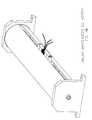
- FIG. 1AOne of the simplest possible linear motion devices is a cylindrical linear voice coil actuator. However, these are limited stroke devices. If long strokes are required, a commutated linear voice coil actuator also known as a linear brushless DC motor can be used (FIG. 1A).
- a linear brushless non-commutated device with flux-focused magnetic circuitscan be found in the moving coil actuator disclosed in U.S. Pat. No. 5,345,206, assigned to BEI Electronics, Inc., the assignee of the subject application. U.S. Pat. No. 5,345,206 is hereby incorporated by reference into the subject application.
- a linear brushless DC motor with ironless armature assembly and a field assemblytailored to achieve a desired constant force versus stroke characteristic, for example, as set forth in FIG. 2.
- the present inventioncomprises an armature assembly, and a field assembly that includes a plurality of permanent magnets each having a length, and a plurality of pole pieces each having a length.
- the ratio between the length of the plurality of permanent magnets and the length of the plurality of pole piecesis tailored to achieve a constant force versus stroke characteristic.
- a brushless DC motorcomprising an armature assembly; and a field assembly positioned with respect to the armature assembly so that an air gap is formed between them.
- the field assemblyincludes a plurality of permanent magnets each having a length, and a plurality of pole pieces each having a length. The ratio between the length of the plurality of permanent magnets and the length of the plurality of pole pieces is selected to provide a sinusoidal distribution of a normal component of flux density in the air gap.
- FIG. 1Ais an illustration of a linear brushless DC motor.
- FIG. 1 Bis a cross section of the linear voice coil actuator disclosed in prior U.S. Pat. No. 5,345,206.
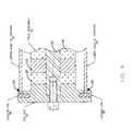
- FIG. 2is simplified cross section showing the housing, field assembly and armature assembly of an embodiment of the linear brushless DC motor of the present invention.
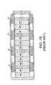
- FIG. 3is a simplified cross section of the field assembly of an embodiment of the linear brushless DC motor of the present invention.
- FIG. 4is a simplified cross section showing details of an end cap of an embodiment of the linear brushless DC motor of the present invention.
- FIG. 5illustrates a sinusoidal distribution of the normal component of the flux density in the air gap in accordance with one embodiment of the present invention.
- FIG. 6illustrates a sinusoidal force versus entire stroke curve obtained for a one phase or combination of two phases of a three-phase motor in accordance with one embodiment of the present invention.
- FIGS. 7A and 7Bare a perspective view and a cross section, respectively, of the armature assembly of one embodiment of the present invention.
- the linear brushless DC motor 10includes an armature assembly 13 , a field assembly 12 “sandwiched” between two end caps 14 , 16 made from soft magnetic material, and two halves 18 , 20 of a housing also made from the soft magnetic material.
- the field assembly 12 , as well as the end caps 14 , 16 and the housing 18 , 20constitute a common magnetic circuit.
- the field assembly 12comprises of a non-magnetic rod 22 , which defines a common field assembly axis, and onto which axially magnetized cylindrical permanent magnets 24 , soft magnetic pole pieces 26 and two axially magnetized end permanent magnets 28 , 30 are installed, for example as set forth in FIG. 3.
- the pole pieces 26are located between the permanent magnets 24 that are magnetized in opposite directions. All the magnets 24 and pole pieces 26 are bonded together. For centering purposes, both ends of the field assembly rod 22 fit into the cylindrical bores 32 provided in the end caps 14 , 16 . The two halves 18 , 20 of the housing fit into the circular cavities 34 also machined in the end caps 14 , 16 . To prevent the angular misalignment of the housing halves 18 , 20 , they are secured in place at both ends with the locking pins 36 . See, FIG. 4.
- the armature assembly 13includes a non-magnetic cylindrical coil base 38 with the cavities for the coils 40 , the three-phase winding and the two mounting brackets 42 , 44 to be connected to the load, as illustrated in FIG. 7.
- the armature assembly 13may slide on motor's own linear bearings (not shown) or may be supported by the linear bearings of the load.
Landscapes
- Physics & Mathematics (AREA)
- Electromagnetism (AREA)
- Engineering & Computer Science (AREA)
- Power Engineering (AREA)
- Chemical & Material Sciences (AREA)
- Combustion & Propulsion (AREA)
- Linear Motors (AREA)
Abstract
Description
- The present application claims priority under 35 U.S.C. §119(e) from provisional application No. 60/258,205, filed Dec. 26, 2000.[0001]
- The present invention relates generally to linear motion devices, and in particular to a linear brushless DC motor with an ironless armature assembly and substantially constant force throughout its stroke.[0002]
- One of the simplest possible linear motion devices is a cylindrical linear voice coil actuator. However, these are limited stroke devices. If long strokes are required, a commutated linear voice coil actuator also known as a linear brushless DC motor can be used (FIG. 1A). An example of a linear brushless non-commutated device with flux-focused magnetic circuits can be found in the moving coil actuator disclosed in U.S. Pat. No. 5,345,206, assigned to BEI Electronics, Inc., the assignee of the subject application. U.S. Pat. No. 5,345,206 is hereby incorporated by reference into the subject application.[0003]
- When linear motion devices are used in a servo system, the mass of a moving part (armature assembly) should be minimized. In addition, all the forces created by a motor, except for the force in the direction of motion, should be eliminated or minimized. And finally, to achieve a smooth operation, the force developed by a servomotor should remain constant throughout the stroke.[0004]
- It is therefore an object of the present invention to provide a linear motion device that has a long stroke and moving parts of low mass.[0005]
- It is another object of the present invention to provide a linear motion device in the form of a linear brushless DC motor in which the forces created by the motor, other than in the direction of motion, are minimized.[0006]
- It is a further object of the present invention to provide a linear brushless DC motor having a smooth operation in which the force developed remains constant throughout the stroke.[0007]
- It is a still further object of the present invention to provide a linear brushless DC motor having a smooth operation in which the force developed remains constant throughout the stroke by using a sinusoidal commutation of a three phase motor.[0008]
- In accordance with the present invention there is provided a linear brushless DC motor with ironless armature assembly and a field assembly tailored to achieve a desired constant force versus stroke characteristic, for example, as set forth in FIG. 2.[0009]
- The present invention comprises an armature assembly, and a field assembly that includes a plurality of permanent magnets each having a length, and a plurality of pole pieces each having a length. The ratio between the length of the plurality of permanent magnets and the length of the plurality of pole pieces is tailored to achieve a constant force versus stroke characteristic.[0010]
- In accordance with the present invention, a brushless DC motor is provided comprising an armature assembly; and a field assembly positioned with respect to the armature assembly so that an air gap is formed between them. The field assembly includes a plurality of permanent magnets each having a length, and a plurality of pole pieces each having a length. The ratio between the length of the plurality of permanent magnets and the length of the plurality of pole pieces is selected to provide a sinusoidal distribution of a normal component of flux density in the air gap.[0011]
- These and other objectives, features and advantages of the present invention will be more readily understood upon consideration of the following detailed description of the invention and the accompanying drawings.[0012]
- FIG. 1A is an illustration of a linear brushless DC motor.[0013]
- FIG. 1 B is a cross section of the linear voice coil actuator disclosed in prior U.S. Pat. No. 5,345,206.[0014]
- FIG. 2 is simplified cross section showing the housing, field assembly and armature assembly of an embodiment of the linear brushless DC motor of the present invention.[0015]
- FIG. 3 is a simplified cross section of the field assembly of an embodiment of the linear brushless DC motor of the present invention.[0016]
- FIG. 4 is a simplified cross section showing details of an end cap of an embodiment of the linear brushless DC motor of the present invention.[0017]
- FIG. 5 illustrates a sinusoidal distribution of the normal component of the flux density in the air gap in accordance with one embodiment of the present invention.[0018]
- FIG. 6 illustrates a sinusoidal force versus entire stroke curve obtained for a one phase or combination of two phases of a three-phase motor in accordance with one embodiment of the present invention.[0019]
- FIGS. 7A and 7B are a perspective view and a cross section, respectively, of the armature assembly of one embodiment of the present invention.[0020]
- According to the present invention, the linear[0021]
brushless DC motor 10 includes anarmature assembly 13, afield assembly 12 “sandwiched” between twoend caps halves 18,20 of a housing also made from the soft magnetic material. Thefield assembly 12, as well as theend caps housing 18,20 constitute a common magnetic circuit. - The[0022]
field assembly 12 comprises of anon-magnetic rod 22, which defines a common field assembly axis, and onto which axially magnetized cylindricalpermanent magnets 24, softmagnetic pole pieces 26 and two axially magnetized endpermanent magnets - The[0023]
pole pieces 26 are located between thepermanent magnets 24 that are magnetized in opposite directions. All themagnets 24 andpole pieces 26 are bonded together. For centering purposes, both ends of thefield assembly rod 22 fit into thecylindrical bores 32 provided in theend caps halves 18,20 of the housing fit into thecircular cavities 34 also machined in theend caps housing halves 18,20, they are secured in place at both ends with thelocking pins 36. See, FIG. 4. - Although the configuration of the magnetic components of the linear motor of the present invention is similar to that of a moving coil actuator disclosed in U.S. Pat. No. 5,345,206 to Morcos, which is assigned to BEI Electronics, Inc., assignee of the subject application, there are two substantial differences:[0024]
- 1) The design of U.S. Pat. No. 5,345,206 was aimed to create flux-focused magnetic circuits whereas the present invention allows one to achieve a sinusoidal distribution of the normal component of the flux density in the air gap, as illustrated in FIG. 5. The sinusoidal distribution is obtained by selecting the appropriate ratio between the length of the permanent magnets and the length of the pole pieces. For example, referring to the pole pieces and the permanent magnets (other than the end permanent magnets) in FIG. 3, one such suitable ratio can be a pole piece length which is two-thirds (⅔) the length of the permanent magnet. The end magnet length was also selected accordingly.[0025]
- 2) In order to get a sinusoidal force vs. entire stroke curve for one phase or a combination of the two phases of a three-phase motor, such as shown in FIG. 6, special attention was paid to selection of the proper ratio between the pole piece length (l[0026]p·p·) and the length of the end pole piece (IE·P·P) which is an integral part of the end cap. Referring to FIG. 2, an example is shown of one such suitable ratio which is an end pole piece length (IE·P·P) which is one-half (½) the pole piece length (lp·p·).
- The[0027]
armature assembly 13 includes a non-magneticcylindrical coil base 38 with the cavities for thecoils 40, the three-phase winding and the twomounting brackets - The[0028]
armature assembly 13 may slide on motor's own linear bearings (not shown) or may be supported by the linear bearings of the load. - The terms and expressions which have been employed herein are intended as terms of description and not of limitation, and there is no intent in the use of such terms and expressions of excluding equivalents of the features shown and described, or portions thereof, it being recognized that various modifications are possible within the scope of the invention claimed.[0029]
Claims (26)
Priority Applications (1)
| Application Number | Priority Date | Filing Date | Title |
|---|---|---|---|
| US10/032,358US6800966B2 (en) | 2000-12-26 | 2001-12-21 | Linear brushless DC motor with ironless armature assembly |
Applications Claiming Priority (2)
| Application Number | Priority Date | Filing Date | Title |
|---|---|---|---|
| US25820500P | 2000-12-26 | 2000-12-26 | |
| US10/032,358US6800966B2 (en) | 2000-12-26 | 2001-12-21 | Linear brushless DC motor with ironless armature assembly |
Publications (2)
| Publication Number | Publication Date |
|---|---|
| US20020079997A1true US20020079997A1 (en) | 2002-06-27 |
| US6800966B2 US6800966B2 (en) | 2004-10-05 |
Family
ID=22979543
Family Applications (1)
| Application Number | Title | Priority Date | Filing Date |
|---|---|---|---|
| US10/032,358Expired - LifetimeUS6800966B2 (en) | 2000-12-26 | 2001-12-21 | Linear brushless DC motor with ironless armature assembly |
Country Status (6)
| Country | Link |
|---|---|
| US (1) | US6800966B2 (en) |
| EP (1) | EP1348250B1 (en) |
| JP (1) | JP2004518391A (en) |
| CN (1) | CN1682423A (en) |
| ES (1) | ES2549852T3 (en) |
| WO (1) | WO2002056447A2 (en) |
Cited By (5)
| Publication number | Priority date | Publication date | Assignee | Title |
|---|---|---|---|---|
| EP1858142A1 (en) | 2006-05-16 | 2007-11-21 | Technische Universität Kaiserlautern | Linear motor |
| US20080150385A1 (en)* | 2004-12-23 | 2008-06-26 | Abb Oy | Rotor Structure for a Permanent-Magnet Machine |
| CN102005892A (en)* | 2010-11-24 | 2011-04-06 | 南京理工大学 | An Electromagnetic Linear Actuator Using Axially Magnetized Permanent Magnets |
| US20160010619A1 (en)* | 2012-10-29 | 2016-01-14 | Reed E. Phillips | Linear faraday induction generator for the generation of electrical power from ocean wave kinetic energy and arrangements thereof |
| EP2566021A3 (en)* | 2011-09-05 | 2017-01-11 | Sanyo Denki Co., Ltd. | Electric machine with linear mover |
Families Citing this family (15)
| Publication number | Priority date | Publication date | Assignee | Title |
|---|---|---|---|---|
| WO2002013211A1 (en)* | 2000-08-03 | 2002-02-14 | Kelly H P G | Electrical short stroke linear actuator |
| US7040481B1 (en)* | 2002-01-08 | 2006-05-09 | Anorad Corporation | Apparatus, method of manufacturing and method of using a linear actuator |
| CN100433512C (en)* | 2003-07-03 | 2008-11-12 | 云南变压器电气股份有限公司 | Linear one-way DC motor for driving magnetic suspension train |
| WO2007103937A2 (en)* | 2006-03-06 | 2007-09-13 | General Innovations, Inc. | Positionally sequenced loudspeaker system |
| DE112007001702T5 (en)* | 2006-07-26 | 2009-05-28 | Kabushiki Kaisha Yaskawa Denki, Kitakyushu | Cylindrical linear motor armature, cylindrical linear motor field pole and cylindrical linear motor using same |
| JP5087333B2 (en)* | 2007-07-12 | 2012-12-05 | 株式会社アイエイアイ | Linear actuator |
| US8076877B2 (en)* | 2008-10-17 | 2011-12-13 | Oteman David G | System and method for controlling power balance in an electrical/mechanical system |
| USD661262S1 (en)* | 2009-10-26 | 2012-06-05 | Nichia Corporation | Light emitting diode |
| CN101710778B (en)* | 2009-12-14 | 2012-05-23 | 北京理工大学 | Linear generator secondary level and control method |
| US8415838B1 (en)* | 2010-07-19 | 2013-04-09 | Moticont | Linear motor with two magnets and a coil carrier having multiple winding areas with each area having a section of a coil wound with one continuous wire with the winding in opposite directions in spaced apart winding areas |
| JP5872108B2 (en)* | 2013-04-12 | 2016-03-01 | 三菱電機株式会社 | Mover and linear motor |
| CN104518594B (en)* | 2013-09-27 | 2017-04-19 | 大银微系统股份有限公司 | Rod type motor mover improved structure |
| WO2017023303A1 (en) | 2015-08-05 | 2017-02-09 | Stren Microlift Technology, Llc | Hydraulic pumping system for use with a subterranean well |
| WO2017155788A1 (en)* | 2016-03-08 | 2017-09-14 | Weatherford Technology Holdings, Llc | Position sensing for wellsite pumping unit |
| CN107623426A (en)* | 2017-07-28 | 2018-01-23 | 柴民 | A kind of linear actuating device and linear electric machine |
Citations (9)
| Publication number | Priority date | Publication date | Assignee | Title |
|---|---|---|---|---|
| US3149255A (en)* | 1962-03-23 | 1964-09-15 | H & T Electrical Products | Electrical reciprocating motor |
| US4363980A (en)* | 1979-06-05 | 1982-12-14 | Polaroid Corporation | Linear motor |
| US4785816A (en)* | 1985-01-14 | 1988-11-22 | Johnson & Johnson Ultrasound Inc. | Ultrasonic transducer probe assembly |
| US5345206A (en)* | 1992-11-24 | 1994-09-06 | Bei Electronics, Inc. | Moving coil actuator utilizing flux-focused interleaved magnetic circuit |
| US5434549A (en)* | 1992-07-20 | 1995-07-18 | Tdk Corporation | Moving magnet-type actuator |
| US5840134A (en)* | 1996-09-30 | 1998-11-24 | Eastman Kodak Company | Functionally gradient permanent magnet actuators |
| US5896076A (en)* | 1997-12-29 | 1999-04-20 | Motran Ind Inc | Force actuator with dual magnetic operation |
| US6157100A (en)* | 1998-07-17 | 2000-12-05 | Rollei Fototechnic Gmbh | Electromagnetic drive for a focal-plane shutter |
| US6417583B1 (en)* | 1999-10-08 | 2002-07-09 | Matsushita Electric Industrial Co., Ltd. | Linear actuator with movable magnets |
Family Cites Families (2)
| Publication number | Priority date | Publication date | Assignee | Title |
|---|---|---|---|---|
| US6239516B1 (en)* | 1998-04-06 | 2001-05-29 | Kollmorgan Corporation | High performance ironless linear motor with supported windings |
| US6388417B1 (en)* | 1999-12-06 | 2002-05-14 | Macrosonix Corporation | High stability dynamic force motor |
- 2001
- 2001-12-21JPJP2002556997Apatent/JP2004518391A/enactivePending
- 2001-12-21USUS10/032,358patent/US6800966B2/ennot_activeExpired - Lifetime
- 2001-12-21EPEP01988414.7Apatent/EP1348250B1/ennot_activeExpired - Lifetime
- 2001-12-21CNCNA018228763Apatent/CN1682423A/enactivePending
- 2001-12-21WOPCT/US2001/050594patent/WO2002056447A2/ennot_activeApplication Discontinuation
- 2001-12-21ESES01988414.7Tpatent/ES2549852T3/ennot_activeExpired - Lifetime
Patent Citations (9)
| Publication number | Priority date | Publication date | Assignee | Title |
|---|---|---|---|---|
| US3149255A (en)* | 1962-03-23 | 1964-09-15 | H & T Electrical Products | Electrical reciprocating motor |
| US4363980A (en)* | 1979-06-05 | 1982-12-14 | Polaroid Corporation | Linear motor |
| US4785816A (en)* | 1985-01-14 | 1988-11-22 | Johnson & Johnson Ultrasound Inc. | Ultrasonic transducer probe assembly |
| US5434549A (en)* | 1992-07-20 | 1995-07-18 | Tdk Corporation | Moving magnet-type actuator |
| US5345206A (en)* | 1992-11-24 | 1994-09-06 | Bei Electronics, Inc. | Moving coil actuator utilizing flux-focused interleaved magnetic circuit |
| US5840134A (en)* | 1996-09-30 | 1998-11-24 | Eastman Kodak Company | Functionally gradient permanent magnet actuators |
| US5896076A (en)* | 1997-12-29 | 1999-04-20 | Motran Ind Inc | Force actuator with dual magnetic operation |
| US6157100A (en)* | 1998-07-17 | 2000-12-05 | Rollei Fototechnic Gmbh | Electromagnetic drive for a focal-plane shutter |
| US6417583B1 (en)* | 1999-10-08 | 2002-07-09 | Matsushita Electric Industrial Co., Ltd. | Linear actuator with movable magnets |
Cited By (7)
| Publication number | Priority date | Publication date | Assignee | Title |
|---|---|---|---|---|
| US20080150385A1 (en)* | 2004-12-23 | 2008-06-26 | Abb Oy | Rotor Structure for a Permanent-Magnet Machine |
| US8084910B2 (en)* | 2004-12-23 | 2011-12-27 | Abb Oy | Rotor structure for a permanent-magnet machine |
| EP1858142A1 (en) | 2006-05-16 | 2007-11-21 | Technische Universität Kaiserlautern | Linear motor |
| CN102005892A (en)* | 2010-11-24 | 2011-04-06 | 南京理工大学 | An Electromagnetic Linear Actuator Using Axially Magnetized Permanent Magnets |
| EP2566021A3 (en)* | 2011-09-05 | 2017-01-11 | Sanyo Denki Co., Ltd. | Electric machine with linear mover |
| US20160010619A1 (en)* | 2012-10-29 | 2016-01-14 | Reed E. Phillips | Linear faraday induction generator for the generation of electrical power from ocean wave kinetic energy and arrangements thereof |
| US9644601B2 (en)* | 2012-10-29 | 2017-05-09 | Energystics, Ltd. | Linear faraday induction generator for the generation of electrical power from ocean wave kinetic energy and arrangements thereof |
Also Published As
| Publication number | Publication date |
|---|---|
| US6800966B2 (en) | 2004-10-05 |
| EP1348250A2 (en) | 2003-10-01 |
| EP1348250B1 (en) | 2015-09-30 |
| WO2002056447A3 (en) | 2003-03-06 |
| CN1682423A (en) | 2005-10-12 |
| ES2549852T3 (en) | 2015-11-02 |
| WO2002056447A2 (en) | 2002-07-18 |
| JP2004518391A (en) | 2004-06-17 |
Similar Documents
| Publication | Publication Date | Title |
|---|---|---|
| US6800966B2 (en) | Linear brushless DC motor with ironless armature assembly | |
| US6522035B1 (en) | Forcer and associated three phase linear motor system | |
| US7456528B2 (en) | High performance linear motor and magnet assembly therefor | |
| US6614137B2 (en) | Linear motor, driving and control system thereof and manufacturing method thereof | |
| JP2008245475A (en) | Moving coil linear motor | |
| US4837467A (en) | Linear motor with angularly indexed magnetic poles | |
| US7471018B2 (en) | Linear motor and manufacturing method of linear motor | |
| JPS61180019A (en) | magnetic bearing | |
| EP0630098A2 (en) | Composite magnet stepper/torquer motor | |
| JPS62118755A (en) | Ac rectilinear moving type motor | |
| JPH1155907A (en) | Electromagnetic driver having moving permanent magnet | |
| US4908592A (en) | Electromagnetic actuating device | |
| US20120205992A1 (en) | Transverse flux electrical motor | |
| JP4513116B2 (en) | Linear motor | |
| JPH1169754A (en) | Movable permanent magnet dc linear motor | |
| JPH06165474A (en) | Moving-magnet type linear dc motor | |
| JP2789543B2 (en) | XY table | |
| US20250070634A1 (en) | Linear electric motor | |
| JPH08182302A (en) | Bearing for linear motor | |
| JPH08163850A (en) | Single pole dc linear motor | |
| JP3268033B2 (en) | Actuator | |
| JPH08275420A (en) | Magnetic circuit and method for assembling magnetic pole magnets thereof | |
| JP3458922B2 (en) | Voice coil type linear motor | |
| JPH08140330A (en) | Moving magnet linear motor | |
| JPH0591710A (en) | Linear motor for swing operation |
Legal Events
| Date | Code | Title | Description |
|---|---|---|---|
| AS | Assignment | Owner name:BEI TECHNOLOGIES, INC., CALIFORNIA Free format text:ASSIGNMENT OF ASSIGNORS INTEREST;ASSIGNOR:GODKIN, MIKHAIL;REEL/FRAME:012422/0985 Effective date:20011214 | |
| STCF | Information on status: patent grant | Free format text:PATENTED CASE | |
| FPAY | Fee payment | Year of fee payment:4 | |
| AS | Assignment | Owner name:CUSTOM SENSORS & TECHNOLOGIES, INC., CALIFORNIA Free format text:CHANGE OF NAME;ASSIGNOR:BEI TECHNOLOGIES, INC.;REEL/FRAME:025026/0793 Effective date:20060406 | |
| REMI | Maintenance fee reminder mailed | ||
| FPAY | Fee payment | Year of fee payment:8 | |
| SULP | Surcharge for late payment | Year of fee payment:7 | |
| AS | Assignment | Owner name:DEUTSCHE BANK AG NEW YORK BRANCH, AS COLLATERAL AG Free format text:SECURITY AGREEMENT;ASSIGNORS:BEI SENSORS & SYSTEMS COMPANY, INC.;CUSTOM SENSORS & TECHNOLOGIES, INC;CRYDOM, INC.;AND OTHERS;REEL/FRAME:033888/0700 Effective date:20140930 | |
| AS | Assignment | Owner name:BEI SENSORS & SYSTEMS COMPANY, INC., CALIFORNIA Free format text:RELEASE BY SECURED PARTY;ASSIGNOR:DEUTSCHE BANK AG NEW YORK BRANCH;REEL/FRAME:037196/0174 Effective date:20151201 Owner name:KAVLICO CORPORATION, CALIFORNIA Free format text:RELEASE BY SECURED PARTY;ASSIGNOR:DEUTSCHE BANK AG NEW YORK BRANCH;REEL/FRAME:037196/0174 Effective date:20151201 Owner name:CUSTOM SENSORS & TECHNOLOGIES, INC., CALIFORNIA Free format text:RELEASE BY SECURED PARTY;ASSIGNOR:DEUTSCHE BANK AG NEW YORK BRANCH;REEL/FRAME:037196/0174 Effective date:20151201 Owner name:CRYDOM, INC., CALIFORNIA Free format text:RELEASE BY SECURED PARTY;ASSIGNOR:DEUTSCHE BANK AG NEW YORK BRANCH;REEL/FRAME:037196/0174 Effective date:20151201 Owner name:BEI TECHNOLOGIES, INC., CALIFORNIA Free format text:RELEASE BY SECURED PARTY;ASSIGNOR:DEUTSCHE BANK AG NEW YORK BRANCH;REEL/FRAME:037196/0174 Effective date:20151201 | |
| AS | Assignment | Owner name:MORGAN STANLEY SENIOR FUNDING, INC., NEW YORK Free format text:SECURITY INTEREST;ASSIGNORS:BEI NORTH AMERICA LLC;CRYDOM, INC.;CUSTOM SENSORS & TECHNOLOGIES, INC.;AND OTHERS;REEL/FRAME:037927/0605 Effective date:20160224 | |
| FPAY | Fee payment | Year of fee payment:12 |