US20020079859A1 - Efficiency maximizing motor controller and method - Google Patents
Efficiency maximizing motor controller and methodDownload PDFInfo
- Publication number
- US20020079859A1 US20020079859A1US09/748,773US74877300AUS2002079859A1US 20020079859 A1US20020079859 A1US 20020079859A1US 74877300 AUS74877300 AUS 74877300AUS 2002079859 A1US2002079859 A1US 2002079859A1
- Authority
- US
- United States
- Prior art keywords
- current
- electrical communication
- induction motor
- dsp
- motor
- Prior art date
- Legal status (The legal status is an assumption and is not a legal conclusion. Google has not performed a legal analysis and makes no representation as to the accuracy of the status listed.)
- Granted
Links
- 238000000034methodMethods0.000titleclaimsabstractdescription14
- 230000006698inductionEffects0.000claimsabstractdescription109
- 238000005457optimizationMethods0.000claimsabstractdescription8
- 230000005669field effectEffects0.000claimsabstractdescription7
- 238000004891communicationMethods0.000claimsdescription107
- 238000005259measurementMethods0.000claimsdescription24
- 230000007935neutral effectEffects0.000claimsdescription13
- 239000003990capacitorSubstances0.000claimsdescription12
- 238000012544monitoring processMethods0.000claimsdescription10
- 238000010304firingMethods0.000claimsdescription8
- 230000006855networkingEffects0.000claimsdescription8
- 230000004044responseEffects0.000claimsdescription5
- 230000001627detrimental effectEffects0.000claimsdescription4
- 239000000835fiberSubstances0.000claimsdescription4
- 230000006872improvementEffects0.000claimsdescription3
- 238000012937correctionMethods0.000claims1
- 238000004364calculation methodMethods0.000abstractdescription5
- 238000010586diagramMethods0.000description37
- 238000002955isolationMethods0.000description5
- 230000007423decreaseEffects0.000description4
- 230000000694effectsEffects0.000description3
- 238000004458analytical methodMethods0.000description2
- 239000011324beadSubstances0.000description2
- 230000008859changeEffects0.000description2
- 238000006243chemical reactionMethods0.000description2
- 230000003247decreasing effectEffects0.000description2
- 241001635479Coris bulbifronsSpecies0.000description1
- 230000006978adaptationEffects0.000description1
- 230000003044adaptive effectEffects0.000description1
- 238000013473artificial intelligenceMethods0.000description1
- 230000033228biological regulationEffects0.000description1
- 230000008878couplingEffects0.000description1
- 238000010168coupling processMethods0.000description1
- 238000005859coupling reactionMethods0.000description1
- 230000007812deficiencyEffects0.000description1
- 238000013461designMethods0.000description1
- 230000003467diminishing effectEffects0.000description1
- 238000001914filtrationMethods0.000description1
- 230000001939inductive effectEffects0.000description1
- 238000012986modificationMethods0.000description1
- 230000004048modificationEffects0.000description1
- 239000003607modifierSubstances0.000description1
- 230000008569processEffects0.000description1
- 230000001681protective effectEffects0.000description1
- 238000006467substitution reactionMethods0.000description1
- 238000004804windingMethods0.000description1
Images


Classifications
- H—ELECTRICITY
- H02—GENERATION; CONVERSION OR DISTRIBUTION OF ELECTRIC POWER
- H02P—CONTROL OR REGULATION OF ELECTRIC MOTORS, ELECTRIC GENERATORS OR DYNAMO-ELECTRIC CONVERTERS; CONTROLLING TRANSFORMERS, REACTORS OR CHOKE COILS
- H02P27/00—Arrangements or methods for the control of AC motors characterised by the kind of supply voltage
- H02P27/02—Arrangements or methods for the control of AC motors characterised by the kind of supply voltage using supply voltage with constant frequency and variable amplitude
Definitions
- This inventionrelates to control of electrical current for efficiency increase and protective powering of electrical motors.
- [0006]provides soft starts of motors for eliminating extra power consumption, for decreasing motor wear and for decreasing wear of devices coupled to the motors from full-power, fast startups of motors;
- [0007]provides consumption of bare minimum amounts of electrical power for selectively no-load and part-load operation of motors at design motor speeds in order to save up to seventy percent of electrical power required for full-load operation;
- [0008]provides motor-parameter off-switching and selective on-switching for fault protection against power surges, power deficiencies, motor stalling, overload, excessive heat or cold and other extraneous problems
- [0011]can be used on both single-phase and three-phase motors and on nearly all sizes of motors for nearly all consumer and industrial applications of motors.
- This inventionaccomplishes these and other objectives with an efficiency-maximizing motor controller and method in which an induction motor has a digital signal processor (DSP) that calculates and optimizes supply of current for existent motor loading from a mains voltage through a current-control element.
- the current-control elementcan include a standard triac, a field-effect transistor, an insulated gate bipolar transistor, a 3 quadrant triac or other select control element.
- This inventionuses this and other motor characteristics to calculate optimum firing angles, firing durations and firing current for dynamically adaptive triacs in order to achieve motor horsepower adaptively to its work loading at the optimum rotational speed.
- Digital calculation and motor-control feedback of this and other motor parameters in millionths of seconds with this inventionprovide motor-current optimization for all motor-use conditions. Calculation of motor-load requirement for current and supply of that current are effectively simultaneous.
- FIG. 1is a block diagram of the efficiency-maximization motor controller
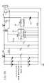
- FIG. 2is an electrical diagram of an analog signal conditioner phase “A”
- FIG. 3is an electrical diagram of a second amplifier stage for the FIG. 2 signal conditioner
- FIG. 4is an electrical diagram of a second capacitor for the FIG. 2 ground virtual circuit
- FIG. 5is an electrical diagram of an analog signal conditioner phase “B”
- FIG. 6is an electrical diagram of a second amplifier stage for the FIG. 5 signal conditioner
- FIG. 7is an electrical diagram of a second capacitor for the FIG. 5 ground virtual circuit
- FIG. 8is an electrical diagram of an analog signal conditioner phase “C”
- FIG. 9is an electrical diagram of a second amplifier stage for the FIG. 8 signal conditioner
- FIG. 10is an electrical diagram of a second capacitor for the FIG. 2 signal conditioner
- FIG. 11is a shrunk diagram of a digital signal processor (DSP);
- FIG. 11Ais an un-shrunk diagram of a top-left portion of the FIG. 11 shrunk diagram
- FIG. 11Bis an un-shrunk diagram of a top-right portion of the FIG. 11 shrunk diagram
- FIG. 11Cis an un-shrunk diagram of a bottom-left portion of the FIG. 11 shrunk diagram
- FIG. 11Dis an un-shrunk diagram of a bottom-right portion of the FIG. 11 shrunk diagram
- FIG. 12is an electrical diagram of a double header assembly for the DSP
- FIG. 13is an electrical diagram of a single header assembly for the DSP
- FIG. 14is an electrical diagram of a jumper assembly for the DSP
- FIG. 15is an electrical diagram of an activity indicator for an activity LED for the DSP
- FIG. 16is an electrical diagram of a ground for the DSP
- FIG. 17is an electrical diagram of a time clock-out switch for the DSP
- FIG. 18is an electrical diagram of a communications port for the debugger and programing port
- FIG. 19is an electrical diagram of a triac three-phase driver for a motor triac
- FIGS. 20 - 24are electrical diagrams of power-connection elements for a single-phase triac
- FIG. 25is an electrical diagram of an IGBT three-phase driver
- FIG. 26is an electrical diagram of an IGBT single-phase connection
- FIGS. 27 - 28are electrical diagrams of communications connections to the outside world for use on personal computers;
- FIG. 29is an electrical diagram of a main PSU
- FIG. 30is an electrical diagram of a power conditioner
- FIGS. 31 - 32are electrical diagrams of an ISO-PSU
- FIG. 33is an electrical diagram of three-phase IGBT power module
- FIG. 34is an electrical diagram of three-phase IGBT power connection
- FIG. 35is an electrical diagram of three-phase triac power module.
- FIG. 1Electrical power for an induction motor 1 from a main power supply 2 is applied through a shunt resistor 3 in a mains neutral 4 line and through a predetermined control element 5 in a mains line 6 in electrical communication with the power supply 2 .
- the predetermined control element 5can be selected from a class of control elements that include a triac, a field-effect transistor (FET), an insulated gate bipolar transistor (IGBT) device, an SCR, and a 3 quadrant triac.
- a voltage analog-to-digital (A/D) converter 7is in electrical communication intermediate the power supply 2 and a digital signal processor (DSP) 8 with mains voltage being applied to the voltage A/D converter 7 . Output of the voltage A/D converter 7 is applied to the DSP 8 for voltage measurement.
- DSPdigital signal processor
- a volts zero-crossing detector 9is in electrical communication intermediate the power supply 2 and the digital signal processor (DSP) 8 with mains voltage being applied to the volts zero-crossing detector 9 . Output of the volts zero-crossing detector 9 is applied to the DSP 8 for phase-angle measurement of volts.
- DSPdigital signal processor
- a current A/D converter 10is in electrical communication intermediate the power supply 2 and the digital signal processor (DSP) 8 with current to drive the induction motor 1 being monitored by the shunt resistor 3 and with the current being applied to the current A/D converter 10 through the shunt resistor 3 . Output of the current A/D converter 10 is applied to the DSP 8 for current measurement.
- DSPdigital signal processor
- a current zero-crossing detector 11is in electrical communication intermediate the power supply 2 and the digital signal processor (DSP) 8 with the current being applied to the current zero-crossing detector 11 through the shunt resistor 3 . Output of the current zero-crossing detector 11 is applied to the DSP 8 for time and phase-angle measurements of current relative to voltage.
- DSPdigital signal processor
- the DSP 8is a micro-controller having architecture to compute predetermined parameters of the induction motor 1 selectively and for controlling current for the induction motor 1 in response to the predetermined parameters.
- An optoelectronically (opto) isolated driver 12is in electrical communication intermediate the DSP 8 and the control element 5 .
- a switching controller 13is in electrical communication intermediate the opto isolated driver 12 and the control element 5 .
- a control attachment 14is in control communication intermediate the DSP and a class of control connectors 15 or connector ports that include serial connectors RS232, serial connectors RS485, Control Area Network (CAN), ethernet, Universal Serial Bus (USB), TCPIP, MODBUS, MODBUS+, wireless, fiber optics, custom utility connectors, and a manual control switch for motor-current-optimization selectively.
- serial connectors RS232serial connectors RS485, Control Area Network (CAN), ethernet, Universal Serial Bus (USB), TCPIP, MODBUS, MODBUS+, wireless, fiber optics, custom utility connectors, and a manual control switch for motor-current-optimization selectively.
- CANControl Area Network
- USBUniversal Serial Bus
- the predetermined parameters of the induction motor 1 that the DSP 8 has computer architecture to compute for controlling current for the induction motor 1include (a) energy savings resulting from predeterminedly selected motor uses; (b) motor soft-start requirements for current to prevent its predeterminedly fast starting; (c) motor stop requirements for current to prevent its predeterminedly fast stopping; (d) motor random-start requirements for current to provide optimum current for its predeterminedly random starting; (e) motor remote-start requirements for current to provide optimum current for its predeterminedly remote starting; (f) motor intranet and internet networking requirements for current to provide optimum current for its predetermined intranet and internet networking; (g) comprehensive monitoring of a selection of the induction motor's 1 electrical parameters that include harmonic content, RMS current, power output, watts consumed, VARs, cycle frequency, phase angle, firing angle, PWM, zero-crossing point, and power being saved by predetermined application of the efficiency-maximization motor controller; (h) automatic logging of usage and downtime of the induction motor; (i)
- a potential dividerconnected to power supply 2 A as shown is used to reduce the 120/240 volts to about 1 volt RMS for voltage measurement.
- the potential dividescomprise the resistor group 19 , R 5 +R 7 with R 4 as a trim, together with R 11 , which provides the division.
- the divided voltageis applied through C 2 18 for DC offset isolation to the unity gain follower U 1 B 16 .
- the output of U 1 B 16 symmetrical around the split 30 3.3Vis applied to the DSP for voltage measurement.
- the same signalis applied to U 2 A which is a comparator with a threshold at the split rail potential (zero volts for the AC voltage present there).
- R 8 and R 10provide Hysteresis by applying a small amount of positive feedback.
- the current inputuses a shunt resistor R 17 3 to reduce costs.
- the shuntis differentially connected to U 1 D 20 via C 6 & C 7 for DC isolation to the unity gain differential stage.
- the output of U 1 D 20is connected to the inverting amplifier U 1 C 22 whose gain can be altered by selection of R 16 to match the shunt to different power rated models.
- the output of U 1 C 22is applied to the DSP for current measurement.
- U 2 B 23is a comparator with a threshold at the split rail potential (zero volts for the AC current, represented as a voltage present there).
- R 13 and R 12provide Hysteresis by applying a small amount of positive feedback.
- the shuntIn single phase the shunt is in series with the motor neutral for current measurement, impossible in three phase without isolated A/D converters or Isolation amplifiers, the transformers are much less expensive. Monitoring the split rail voltage and also the 3.3 volt rail in the DSP removes completely any inaccuracies associated with the divider chain to U 1 A 25 , the rail splitter.
- the U 1 D op-amp 20is in electrical communication with a U 1 C amplifier 22 and a U 2 B collector 23 with output to communicate current zero crossing 24 which is shown as IA ZERO CROSS, to the DSP 8 which is shown in FIGS. 1 and 11- 18 .
- AC currentis read as a voltage across the series motor shunt resistor 3 that is shown as R 17 .
- Thisis done by use of the differentially connected op-amp U 1 D 20 in a classic configuration to avoid any “ground loop”conditions created by common impedance coupling. Connection to the shunt resistor 3 is accomplished in a Kelvin configuration where separate monitoring connections are made to the shunt resistor 3 as shown. Differential signals are passed to the op-amp U 1 D 20 via R 14 , R 21 , R 18 and R 21 . Two capacitors, C 6 and C 7 , are used to isolate the DC component on op-amp inputs.
- the differential U 1 D op-amp 20together with the second U 1 C amplifier 22 stage, has sufficient gain to raise the small voltage derived from the shunt resistor 3 to a level appropriate for accurate analog-to-digital conversion within a range consistent with the induction motor 1 requirements.
- This signalis taken from the output of the second-stage amplifier. Simultaneously, this buffered output is applied to U 2 B comparator 23 which senses the zero-crossing point 24 accurately. Hysteresis is used to speed up the edge of the current zero-crossing detector 24 to further enhance accuracy.
- the outputis taken from the open collector output of the U 2 B comparator 23 and passed to a zero-cross input of the DSP 8 .
- the DSP 8is used to process data rapidly for virtually every aspect of the efficiency-maximization motor controller. It runs at thirty MHz and is capable of performing thirty million instructions per second (30 MIPS). Independently, it handles all of the A/D conversions, PWM generation and the timing necessary to make determinations of the period between zero-crossing points. This processor performs all calculations within each and every half cycle period of 8.33 milli-seconds. Simultaneously, the DSP 8 monitors temperature of the motor, reads start/stop switches, monitors all supply voltages, performs all communications, and outputs appropriate drive signals to the TRIAC or the IGBT/MOS-FET, monitors RPM and temperature. Further, the DSP 8 supports “in-system programming” background de-bugging, and an activity LED.
- triac controller 30has an opto-isolated driver, optol 31 , which is an opto-triac that is driven by a Schmitt inverter U 13 A.
- Triac driveinverted from the DSP 8 , shown in FIGS. 1 and 11- 18 , turns on the LED of the optol 31 which, in turn, switches on the internal photo-sensitive triac controller 30 which turns on a main triac Q 7 32 as shown in FIG. 20.
- Resistor R 125 33 and capacitor C 80 34form a snubber network and a transorb device D 49 absorbs and clamps any transients to a magnitude which is harmless to the triac Q 7 32 .
- an IGBT controller 35has a first opto isolator U 25 36 and a second opto isolator U 26 37 that are driven by U 8 A 38 and U 8 B 39 , which in turn drive IGBT device Q 8 40 and IGTB device Q 9 41 .
- Each deviceis controlled independently by the DSP 8 , allowing full control of firing angle. Unlike the triac, this gives full control over the reactive portion of the current Q 9 which reduces substantially to the problems associated with power factor (PF).
- PFpower factor
- the IGBT controller 35can be turned on or off at will. Since the IGBT controller's 35 on cycle is PWM modulated, complete control of rise time, amplitude, and duration are available. This provides much improvement of RFI/EMG, harmonic content and reactive power factor (PF) for part-power operation.
- FIGS. 27 - 28a communications example is shown for a simple RS232 serial port which can be connected to a computer to display all monitor and control functions.
- the DSP 8can support a plurality of control connectors that include but are not limited to (a) Serial Communications RS232; (b) Serial Communications RS845; (c) CAN (Control Area Network); (d) Ethernet; (e) USB (Universal Serial Bus); (f) TCPIP (stack for internet and intranet communications); (g) Modbus; and (h) Modbus+.
- main +5V poweris provided by an “off-line” switching regulator.
- the +5Vis accurately maintained by a feedback loop comprising U 23 42 , U 24 43 and reference D 48 44 .
- U 24 43is an opto isolator.
- U 9 45is a linear low-drop-out regulator which provides +3.3 V for the DSP 8 and other active circuitry.
- Various +3.3V feedsare derived from the main feed, each of which includes LC filtering as appropriate for needs on the circuit blocks.
- a bead inductor L 2 46provides isolation of digital noise from the analog ground system. When IGBT devices are employed, two additional, small, isolated supplies are required. These are similar to the off-line regulator, except that three +18V are produced. In the case of the single-phase embodiment with IGBT Mosfets, only two outputs are required. When triacs are employed, no isolated voltages are required.
- a use method for optimization of electrical current supplied to the induction motor 1has the following steps.
- a no-load phase angle of lag of voltage by currentis predetermined for rotating the induction motor 1 at a predetermined operational speed of rotation without motor-load resistance in excess of the motor-load resistance inherent to the induction motor 1 separately from and independently of motor loading that is applied to an output shaft of the induction motor 1 for output work.
- Current required for rotating the induction motor 1 under a predetermined full load and having a predetermined full-load phase angle of lag of voltage by current for rotating the induction motor 1 maximumly loaded at the predetermined operational speedis predetermined.
- the part-load increase of current requiredis directed to the induction motor 1 from the power supply 2 .
Landscapes
- Engineering & Computer Science (AREA)
- Power Engineering (AREA)
- Control Of Ac Motors In General (AREA)
Abstract
Description
- This invention relates to control of electrical current for efficiency increase and protective powering of electrical motors.[0001]
- Potential for increase in efficiency of electrical motors by regulation of current for their operation has resulted in a variety of motor-electric controllers for its accomplishment. None, however, computes on a microsecond basis the motor-loading needs of electrical motors for electrical current and, accordingly, optimizes the electrical current supplied for predetermined rotational speeds of the motors and, in addition, provide operational analyses and fault protection against hazzards to motors and to rotationally coupled devices in a manner taught by this invention.[0002]
- Examples of most-closely related known but yet different motor-electric controllers are described in the following patent documents. U.S. Pat. No. 5,249,118, issued to Smith on Sep. 28, 1993, described input control of current for a rotational-speed controller that also controlled rate of increase and decrease of rotational speed for computer-controlled machinery. It is representative of a plurality of patents and prior art that relate to control of speed with control of input current in contrast to Applicants' invention for optimization-control of current for predetermined rotational speed of motors. In the Smith patent, as in other variable-speed motors, current to the motors is not optimized at the variable speeds in a manner taught by this invention. Logic, methods and features for accomplishing speed control differ accordingly from the current-optimization control for predetermined speed described by Applicants.[0003]
- Current control for economizing power of motors at operational speeds by control of input current with yet different logic, methods and features are described in the following patent documents. U.S. Pat. No. 4,864,212, issued to Parker on Sep. 5, 1989, described a sine wave power source connected through a triac to a control system with a gate electrode which is energized by a train (sequence) of sawtooth-shaped control signals having a repetition rate which is twice the frequency of the sine wave power source for providing short bursts of energy to decrease total power input for low power requirements at low fixed rates for variable rates of lowspeed operation. U.S. Pat. No. 4,636,702, issued to Hedges on Jan. 13, 1987, described a sample transformer operative to generate a voltage pulse related to inrush-current parameters for control of portions of sine waves of power input to stator windings for diminishing electrical current to a motor during low loading. It is limited further to a “manually settable means” for selecting a maximum value of motor torque during start mode of operation. U.S. Pat. No. 4,382,223, issued to Hedges on May 3, 1983, and an improvement thereof, U.S. Pat. No. 4,414,499 issued to Hedges on Nov. 8, 1983, described use of a small AC generator coupled to a rotor of an electric motor to produce a signal for controlling a sine wave modifier to regulate current to the motor in accordance with load requirements. The load requirements were determined by a difference between an optimal RPM for the motor and an RPM indicated by the small AC generator. U.S. Pat. No. 4,341,984, issued to Parker, et al. on Jul. 27, 1982, is based on a frequency controller to produce at least two output frequencies for different speeds of operation of a motor. Other U.S. patents issued to Parker and/or Hedges, have employed variations of those indicated above.[0004]
- Objects of patentable novelty and utility taught by this invention are to provide an efficiency-maximizing motor controller and method which:[0005]
- provides soft starts of motors for eliminating extra power consumption, for decreasing motor wear and for decreasing wear of devices coupled to the motors from full-power, fast startups of motors;[0006]
- provides consumption of bare minimum amounts of electrical power for selectively no-load and part-load operation of motors at design motor speeds in order to save up to seventy percent of electrical power required for full-load operation;[0007]
- provides motor-parameter off-switching and selective on-switching for fault protection against power surges, power deficiencies, motor stalling, overload, excessive heat or cold and other extraneous problems;[0008]
- provides analyses of motor-operation factors and efficiencies; decreases motor power use and costs;[0009]
- decreases world need and consumption of electrical power; and[0010]
- can be used on both single-phase and three-phase motors and on nearly all sizes of motors for nearly all consumer and industrial applications of motors.[0011]
- This invention accomplishes these and other objectives with an efficiency-maximizing motor controller and method in which an induction motor has a digital signal processor (DSP) that calculates and optimizes supply of current for existent motor loading from a mains voltage through a current-control element. The current-control element can include a standard triac, a field-effect transistor, an insulated gate bipolar transistor, a 3 quadrant triac or other select control element.[0012]
- An induction motor rotating unloaded is predominately an inductor. In this state, the only work being done is to overcome frictional losses and inertial kinetic energy necessary to maintain rotation. Being largely inductive in this state, current lags voltage by nearly ninety degrees. As the motor is loaded increasingly, a phase difference of current lag diminishes. This is a change in phase angle from near ninety degrees to an angle approaching zero degrees of current lag, Accurately computed with artificial intelligence, this change in phase angle is an accurate measure of motor load for which current is required for operation at an optimum rotational speed.[0013]
- This invention uses this and other motor characteristics to calculate optimum firing angles, firing durations and firing current for dynamically adaptive triacs in order to achieve motor horsepower adaptively to its work loading at the optimum rotational speed. Digital calculation and motor-control feedback of this and other motor parameters in millionths of seconds with this invention provide motor-current optimization for all motor-use conditions. Calculation of motor-load requirement for current and supply of that current are effectively simultaneous.[0014]
- The above and other objects, features and advantages of the present invention should become even more readily apparent to those skilled in the art upon a reading of the following detailed description in conjunction with the drawings wherein there is shown and described illustrative embodiments of the invention.[0015]
- This invention is described by appended claims in relation to description of a preferred embodiment with reference to the following drawings which are explained briefly as follows:[0016]
- FIG. 1 is a block diagram of the efficiency-maximization motor controller;[0017]
- FIG. 2 is an electrical diagram of an analog signal conditioner phase “A”;[0018]
- FIG. 3 is an electrical diagram of a second amplifier stage for the FIG. 2 signal conditioner;[0019]
- FIG. 4 is an electrical diagram of a second capacitor for the FIG. 2 ground virtual circuit;[0020]
- FIG. 5 is an electrical diagram of an analog signal conditioner phase “B”;[0021]
- FIG. 6 is an electrical diagram of a second amplifier stage for the FIG. 5 signal conditioner;[0022]
- FIG. 7 is an electrical diagram of a second capacitor for the FIG. 5 ground virtual circuit;[0023]
- FIG. 8 is an electrical diagram of an analog signal conditioner phase “C”;[0024]
- FIG. 9 is an electrical diagram of a second amplifier stage for the FIG. 8 signal conditioner;[0025]
- FIG. 10 is an electrical diagram of a second capacitor for the FIG. 2 signal conditioner;[0026]
- FIG. 11 is a shrunk diagram of a digital signal processor (DSP);[0027]
- FIG. 11A is an un-shrunk diagram of a top-left portion of the FIG. 11 shrunk diagram;[0028]
- FIG. 11B is an un-shrunk diagram of a top-right portion of the FIG. 11 shrunk diagram;[0029]
- FIG. 11C is an un-shrunk diagram of a bottom-left portion of the FIG. 11 shrunk diagram;[0030]
- FIG. 11D is an un-shrunk diagram of a bottom-right portion of the FIG. 11 shrunk diagram;[0031]
- FIG. 12 is an electrical diagram of a double header assembly for the DSP;[0032]
- FIG. 13 is an electrical diagram of a single header assembly for the DSP;[0033]
- FIG. 14 is an electrical diagram of a jumper assembly for the DSP;[0034]
- FIG. 15 is an electrical diagram of an activity indicator for an activity LED for the DSP;[0035]
- FIG. 16 is an electrical diagram of a ground for the DSP;[0036]
- FIG. 17 is an electrical diagram of a time clock-out switch for the DSP;[0037]
- FIG. 18 is an electrical diagram of a communications port for the debugger and programing port;[0038]
- FIG. 19 is an electrical diagram of a triac three-phase driver for a motor triac;[0039]
- FIGS.[0040]20-24 are electrical diagrams of power-connection elements for a single-phase triac;
- FIG. 25 is an electrical diagram of an IGBT three-phase driver;[0041]
- FIG. 26 is an electrical diagram of an IGBT single-phase connection;[0042]
- FIGS.[0043]27-28 are electrical diagrams of communications connections to the outside world for use on personal computers;
- FIG. 29 is an electrical diagram of a main PSU;[0044]
- FIG. 30 is an electrical diagram of a power conditioner; FIGS.[0045]31-32 are electrical diagrams of an ISO-PSU; FIG. 33 is an electrical diagram of three-phase IGBT power module; FIG. 34 is an electrical diagram of three-phase IGBT power connection; and FIG. 35 is an electrical diagram of three-phase triac power module.
- Listed numerically below with reference to the drawings are terms used to describe features of this invention. These terms and numbers assigned to them designate the same features throughout this description.[0046]
- [0047]1. Induction motor
- [0048]2. Power supply
- [0049]2A. single phase power supply
- [0050]2B. additional two phase power supply
- [0051]3. Shunt resistor
- [0052]4. Mains neutral
- [0053]5. Control element
- [0054]6. Mains line
- [0055]7. Voltage A/D converter
- [0056]8. DSP
- [0057]9. Volts zero-crossing detector
- [0058]10. Current A/D converter
- [0059]11. Current zero-crossing detector
- [0060]12. Opto isolated driver
- [0061]13. Switching controller
- [0062]14. Control attachment
- [0063]15. Control connectors
- [0064]16. U1B unity gain follower
- [0065]17. Alternator network
- [0066]18. Capacitor C2
- [0067]19. Resistors
- [0068]20. UlD op-
amp 21.Capacitors 22.U1C amplifier 23.U2B comparator 24. Zerocrossing detector 25.UlA 26.R3 27.R6 28.Rail splitter 29.C19 30.Triac controller 31.Optol 32.Triac Q7 33.Resistor R125 34.Capacitor C80 35.IGBT controller 36. Firstopto isolator U25 37. Secondopto isolator U26 38.U8A 39.U8B 40.IGBT device Q8 41.IGBT device Q9 42.U23 43.U24 44.D48 45.U9 46.Bead inductor L2 47.voltage transformer 48. current transformer - Reference is made first to FIG. 1. Electrical power for an[0069]
induction motor 1 from amain power supply 2 is applied through ashunt resistor 3 in a mains neutral4 line and through apredetermined control element 5 in amains line 6 in electrical communication with thepower supply 2. Thepredetermined control element 5 can be selected from a class of control elements that include a triac, a field-effect transistor (FET), an insulated gate bipolar transistor (IGBT) device, an SCR, and a 3 quadrant triac. - A voltage analog-to-digital (A/D)[0070]
converter 7 is in electrical communication intermediate thepower supply 2 and a digital signal processor (DSP)8 with mains voltage being applied to the voltage A/D converter 7. Output of the voltage A/D converter 7 is applied to theDSP 8 for voltage measurement. - A volts zero-crossing[0071]
detector 9 is in electrical communication intermediate thepower supply 2 and the digital signal processor (DSP)8 with mains voltage being applied to the volts zero-crossingdetector 9. Output of the volts zero-crossingdetector 9 is applied to theDSP 8 for phase-angle measurement of volts. - A current A/[0072]
D converter 10 is in electrical communication intermediate thepower supply 2 and the digital signal processor (DSP)8 with current to drive theinduction motor 1 being monitored by theshunt resistor 3 and with the current being applied to the current A/D converter 10 through theshunt resistor 3. Output of the current A/D converter 10 is applied to theDSP 8 for current measurement. - A current zero-crossing[0073]
detector 11 is in electrical communication intermediate thepower supply 2 and the digital signal processor (DSP)8 with the current being applied to the current zero-crossingdetector 11 through theshunt resistor 3. Output of the current zero-crossingdetector 11 is applied to theDSP 8 for time and phase-angle measurements of current relative to voltage. - The[0074]
DSP 8 is a micro-controller having architecture to compute predetermined parameters of theinduction motor 1 selectively and for controlling current for theinduction motor 1 in response to the predetermined parameters. - An optoelectronically (opto) isolated[0075]
driver 12 is in electrical communication intermediate theDSP 8 and thecontrol element 5. - A switching[0076]
controller 13 is in electrical communication intermediate the opto isolateddriver 12 and thecontrol element 5. - A[0077]
control attachment 14 is in control communication intermediate the DSP and a class ofcontrol connectors 15 or connector ports that include serial connectors RS232, serial connectors RS485, Control Area Network (CAN), ethernet, Universal Serial Bus (USB), TCPIP, MODBUS, MODBUS+, wireless, fiber optics, custom utility connectors, and a manual control switch for motor-current-optimization selectively. - The predetermined parameters of the induction motor[0078]1 that the DSP8 has computer architecture to compute for controlling current for the induction motor1 include (a) energy savings resulting from predeterminedly selected motor uses; (b) motor soft-start requirements for current to prevent its predeterminedly fast starting; (c) motor stop requirements for current to prevent its predeterminedly fast stopping; (d) motor random-start requirements for current to provide optimum current for its predeterminedly random starting; (e) motor remote-start requirements for current to provide optimum current for its predeterminedly remote starting; (f) motor intranet and internet networking requirements for current to provide optimum current for its predetermined intranet and internet networking; (g) comprehensive monitoring of a selection of the induction motor's1 electrical parameters that include harmonic content, RMS current, power output, watts consumed, VARs, cycle frequency, phase angle, firing angle, PWM, zero-crossing point, and power being saved by predetermined application of the efficiency-maximization motor controller; (h) automatic logging of usage and downtime of the induction motor; (i) a running total of energy savings from predetermined use of the efficiency-maximization motor controller; and (j) monitoring the induction motor1 against overload, stalling, loss of phase, over-voltage, under voltage, over-current, under-current, detrimental temperature, low RPM and DC offset.
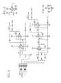
- Referring to FIG. 2, when configured for single phase, and to reduce costs, a potential divider, connected to[0079]
power supply 2A as shown is used to reduce the 120/240 volts to about 1 volt RMS for voltage measurement. The potential divides comprise theresistor group 19, R5+R7 with R4 as a trim, together with R11, which provides the division. The divided voltage is applied throughC2 18 for DC offset isolation to the unitygain follower U1B 16. The output ofU1B 16 symmetrical around thesplit 30 3.3V is applied to the DSP for voltage measurement. The same signal is applied to U2A which is a comparator with a threshold at the split rail potential (zero volts for the AC voltage present there). R8 and R10 provide Hysteresis by applying a small amount of positive feedback. - Likewise, the current input uses a[0080]
shunt resistor R17 3 to reduce costs. The shunt is differentially connected toU1D 20 via C6 & C7 for DC isolation to the unity gain differential stage. The output ofU1D 20 is connected to the invertingamplifier U1C 22 whose gain can be altered by selection of R16 to match the shunt to different power rated models. The output ofU1C 22 is applied to the DSP for current measurement. The same signal is applied toU2B 23 which is a comparator with a threshold at the split rail potential (zero volts for the AC current, represented as a voltage present there). R13 and R12 provide Hysteresis by applying a small amount of positive feedback. - When configured for three phase power with additional two phase[0081]
power supply input 2B all inputs need to be isolated. Voltage and current transformers are used instead of the resistive potential divider network used with onephase power supply 2A as described previously. Avoltage transformer 47 is connected to the circuitry viapower supply 2B, R11 serves as the load on the transformer, and the transformer ratio together with R11 presents the correct voltage level throughC2 18 toU1B 16. Similar circuitry is used for the other two phases as shown in FIGS. 5 and 8. Similarly for three phase three current transformers are used together with a “burden resistor” in place of the shunt. A current transformer is connected topower supply 2B with the primary in series with each motor phase. In single phase the shunt is in series with the motor neutral for current measurement, impossible in three phase without isolated A/D converters or Isolation amplifiers, the transformers are much less expensive. Monitoring the split rail voltage and also the 3.3 volt rail in the DSP removes completely any inaccuracies associated with the divider chain toU1A 25, the rail splitter. - The U[0082]1D op-
amp 20 is in electrical communication with aU1C amplifier 22 and aU2B collector 23 with output to communicate current zero crossing24 which is shown as IA ZERO CROSS, to theDSP 8 which is shown in FIGS. 1 and 11-18. - AC current is read as a voltage across the series[0083]
motor shunt resistor 3 that is shown as R17. This is done by use of the differentially connected op-amp U1D 20 in a classic configuration to avoid any “ground loop”conditions created by common impedance coupling. Connection to theshunt resistor 3 is accomplished in a Kelvin configuration where separate monitoring connections are made to theshunt resistor 3 as shown. Differential signals are passed to the op-amp U1D 20 via R14, R21, R18 and R21. Two capacitors, C6 and C7, are used to isolate the DC component on op-amp inputs. The differential U1D op-amp 20, together with thesecond U1C amplifier 22 stage, has sufficient gain to raise the small voltage derived from theshunt resistor 3 to a level appropriate for accurate analog-to-digital conversion within a range consistent with theinduction motor 1 requirements. - This signal is taken from the output of the second-stage amplifier. Simultaneously, this buffered output is applied to[0084]
U2B comparator 23 which senses the zero-crossing point 24 accurately. Hysteresis is used to speed up the edge of the current zero-crossingdetector 24 to further enhance accuracy. The output is taken from the open collector output of theU2B comparator 23 and passed to a zero-cross input of theDSP 8. - DC isolation is required at both the voltage and current inputs with use of single-supply op-amps and comparators. In order to enable bi-polar signals to pass, the operating point is offset to half of the supply voltage in a “virtual ground” circuit. This topology is achieved by use of[0085]
U1A 25 which hasR3 26 andR6 27 arranged as a rail splitter, splitrail 28, and decoupled byC1 29. - This arrangement gives the virtual ground or split rail extremely low impedance which is at the same AC potential as the analog ground.[0086]
- Referring to FIGS. 1 and 11-[0087]18, the
DSP 8 is used to process data rapidly for virtually every aspect of the efficiency-maximization motor controller. It runs at thirty MHz and is capable of performing thirty million instructions per second (30 MIPS). Independently, it handles all of the A/D conversions, PWM generation and the timing necessary to make determinations of the period between zero-crossing points. This processor performs all calculations within each and every half cycle period of 8.33 milli-seconds. Simultaneously, theDSP 8 monitors temperature of the motor, reads start/stop switches, monitors all supply voltages, performs all communications, and outputs appropriate drive signals to the TRIAC or the IGBT/MOS-FET, monitors RPM and temperature. Further, theDSP 8 supports “in-system programming” background de-bugging, and an activity LED. - Referring to FIGS.[0088]19-24,
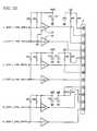
triac controller 30 has an opto-isolated driver,optol 31, which is an opto-triac that is driven by a Schmitt inverter U13A. Triac drive, inverted from theDSP 8, shown in FIGS. 1 and 11-18, turns on the LED of theoptol 31 which, in turn, switches on the internal photo-sensitive triac controller 30 which turns on amain triac Q7 32 as shown in FIG. 20.Resistor R125 33 andcapacitor C80 34 form a snubber network and a transorb device D49 absorbs and clamps any transients to a magnitude which is harmless to thetriac Q7 32. - Referring to FIGS.[0089]25-26, an
IGBT controller 35 has a firstopto isolator U25 36 and a secondopto isolator U26 37 that are driven byU8A 38 andU8B 39, which in turn driveIGBT device Q8 40 andIGTB device Q9 41. Each device is controlled independently by theDSP 8, allowing full control of firing angle. Unlike the triac, this gives full control over the reactive portion of the current Q9 which reduces substantially to the problems associated with power factor (PF). Unlike the triac which stays on until current has ceased to flow, theIGBT controller 35 can be turned on or off at will. Since the IGBT controller's35 on cycle is PWM modulated, complete control of rise time, amplitude, and duration are available. This provides much improvement of RFI/EMG, harmonic content and reactive power factor (PF) for part-power operation. - Referring to FIGS.[0090]27-28, a communications example is shown for a simple RS232 serial port which can be connected to a computer to display all monitor and control functions. Similarly the
DSP 8 can support a plurality of control connectors that include but are not limited to (a) Serial Communications RS232; (b) Serial Communications RS845; (c) CAN (Control Area Network); (d) Ethernet; (e) USB (Universal Serial Bus); (f) TCPIP (stack for internet and intranet communications); (g) Modbus; and (h) Modbus+. - Referring to FIGS.[0091]29-32, for power supply units, main +5V power is provided by an “off-line” switching regulator. The +5V is accurately maintained by a feedback
loop comprising U23 42,U24 43 andreference D48 44.U24 43 is an opto isolator.U9 45 is a linear low-drop-out regulator which provides +3.3 V for theDSP 8 and other active circuitry. Various +3.3V feeds are derived from the main feed, each of which includes LC filtering as appropriate for needs on the circuit blocks. Abead inductor L2 46 provides isolation of digital noise from the analog ground system. When IGBT devices are employed, two additional, small, isolated supplies are required. These are similar to the off-line regulator, except that three +18V are produced. In the case of the single-phase embodiment with IGBT Mosfets, only two outputs are required. When triacs are employed, no isolated voltages are required. - A use method for optimization of electrical current supplied to the[0092]
induction motor 1 has the following steps. For the efficiency-maximization motor controller, a no-load phase angle of lag of voltage by current is predetermined for rotating theinduction motor 1 at a predetermined operational speed of rotation without motor-load resistance in excess of the motor-load resistance inherent to theinduction motor 1 separately from and independently of motor loading that is applied to an output shaft of theinduction motor 1 for output work. Current required for rotating theinduction motor 1 under a predetermined full load and having a predetermined full-load phase angle of lag of voltage by current for rotating theinduction motor 1 maximumly loaded at the predetermined operational speed is predetermined. - With the efficiency-maximization motor controller is calculated any part-load phase angle of the lag of voltage by current for rotating the[0093]
induction motor 1 at the predetermined operational speed of rotation with any added motor-load resistance from any part-loading that is applied to theinduction motor 1. Calculated also with the efficiency-maximization motor controller is any part-load increase of current required for any part-loading of theinduction motor 1 as a part-load percent of a difference between the no-load phase angle and the full-load phase angle. - Then with the efficiency-maximization motor controller, the part-load increase of current required is directed to the[0094]
induction motor 1 from thepower supply 2. - Using the efficiency-maximization motor controller as described, with the[0095]
DSP 8 having computer architecture to compute for the system's predetermined parameters of theinduction motor 1, and with acontrol attachment 14 that is in control communication intermediate theDSP 8 and a predetermined class ofcontrol connectors 15 as diagramed in FIG. 1, at least one of the electrical parameters is entered into the efficiency-maximization motor controller for an objective of operation of theinduction motor 1 through a selectedcontrol connector 15. - A new and useful efficiency-maximization motor controller and method having been described, all such foreseeable modifications, adaptations, substitutions of equivalents, mathematical possibilities of combinations of parts, pluralities of parts, applications and forms thereof as described by the following claims and not precluded by prior art are included in this invention.[0096]
Claims (20)
Priority Applications (2)
| Application Number | Priority Date | Filing Date | Title |
|---|---|---|---|
| US09/748,773US6489742B2 (en) | 2000-12-26 | 2000-12-26 | Efficiency maximizing motor controller and method |
| PCT/US2001/049214WO2002052712A1 (en) | 2000-12-26 | 2001-12-21 | Efficiency maximizing motor controller and method |
Applications Claiming Priority (1)
| Application Number | Priority Date | Filing Date | Title |
|---|---|---|---|
| US09/748,773US6489742B2 (en) | 2000-12-26 | 2000-12-26 | Efficiency maximizing motor controller and method |
Publications (2)
| Publication Number | Publication Date |
|---|---|
| US20020079859A1true US20020079859A1 (en) | 2002-06-27 |
| US6489742B2 US6489742B2 (en) | 2002-12-03 |
Family
ID=25010859
Family Applications (1)
| Application Number | Title | Priority Date | Filing Date |
|---|---|---|---|
| US09/748,773Expired - LifetimeUS6489742B2 (en) | 2000-12-26 | 2000-12-26 | Efficiency maximizing motor controller and method |
Country Status (2)
| Country | Link |
|---|---|
| US (1) | US6489742B2 (en) |
| WO (1) | WO2002052712A1 (en) |
Cited By (35)
| Publication number | Priority date | Publication date | Assignee | Title |
|---|---|---|---|---|
| US20040019439A1 (en)* | 2002-07-23 | 2004-01-29 | Yehia El-Ibiary | Induction motor module and motor incorporating same |
| US20040056622A1 (en)* | 2002-09-23 | 2004-03-25 | Scott Mayhew | System and method for automatic current limit control |
| US20040155622A1 (en)* | 2003-02-12 | 2004-08-12 | Scott Mayhew | System and method for stall detection of a motor |
| US20050109176A1 (en)* | 2003-11-07 | 2005-05-26 | Wilson David N. | Method of cutting carbon and alloy steel |
| US20050162108A1 (en)* | 2003-09-12 | 2005-07-28 | A. O. Smith Corporation | Electric machine and method of operating the electric machine |
| US7102324B2 (en) | 2003-09-12 | 2006-09-05 | A.O. Smith Corporation | Fixed speed drive |
| US20070118307A1 (en)* | 2003-09-30 | 2007-05-24 | Yehia El-Ibiary | Motor parameter estimation method and apparatus |
| KR100810651B1 (en) | 2007-11-09 | 2008-03-06 | 삼화디에스피주식회사 | Power monitoring multi-function motor protection relay |
| US20090051308A1 (en)* | 2007-06-04 | 2009-02-26 | Bin Lu | System and method to determine electric motor efficiency using an equivalent circuit |
| US20100201296A1 (en)* | 2007-12-04 | 2010-08-12 | Oleg Anatolievich Buglaev | Brushless DC Electric Motor |
| US20100277205A1 (en)* | 2007-12-06 | 2010-11-04 | Freescale Semiconductor, Inc. | Semiconductor device and apparatus including semiconductor device |
| CN102004221A (en)* | 2010-08-26 | 2011-04-06 | 沈阳工业大学 | Reciprocal energy feeding test device for actuating mechanism of dual linear induction motors |
| US20110182094A1 (en)* | 2007-08-13 | 2011-07-28 | The Powerwise Group, Inc. | System and method to manage power usage |
| CN102437799A (en)* | 2011-10-21 | 2012-05-02 | 福州大学 | Method for realizing digital signal processor (DSP) control over intermediate frequency single-phase generator inverter |
| CN102832825A (en)* | 2007-08-13 | 2012-12-19 | 智能动力股份有限公司 | IGBT/FET-based energy saving device, system and method |
| US20130043985A1 (en)* | 2011-08-19 | 2013-02-21 | Legendaire Technology Co., Ltd. | Motor control system and the method of controlling motor |
| US20130193891A1 (en)* | 2012-01-27 | 2013-08-01 | Ingersoll-Rand Company | Precision-fastening handheld cordless power tools |
| US8619443B2 (en) | 2010-09-29 | 2013-12-31 | The Powerwise Group, Inc. | System and method to boost voltage |
| US20140028298A1 (en)* | 2010-12-22 | 2014-01-30 | Jan Willem Karel Vietsch | Method of assessing shaft alignment based on energy efficiency |
| US8698446B2 (en) | 2009-09-08 | 2014-04-15 | The Powerwise Group, Inc. | Method to save energy for devices with rotating or reciprocating masses |
| US8698447B2 (en) | 2007-09-14 | 2014-04-15 | The Powerwise Group, Inc. | Energy saving system and method for devices with rotating or reciprocating masses |
| US8810190B2 (en) | 2007-09-14 | 2014-08-19 | The Powerwise Group, Inc. | Motor controller system and method for maximizing energy savings |
| US20140232312A1 (en)* | 2013-02-19 | 2014-08-21 | Whirlpool S.A. | Method for starting a washing machine electric motor |
| US8823314B2 (en) | 2007-09-14 | 2014-09-02 | The Powerwise Group, Inc. | Energy saving system and method for devices with rotating or reciprocating masses |
| US20140301428A1 (en)* | 2011-12-15 | 2014-10-09 | Eutelsat S A | Transmission/reception of microwave signals broadcast by a satellite with an interactive return link using a spread spectrum protocol |
| CN104533383A (en)* | 2014-12-18 | 2015-04-22 | 宝鸡石油机械有限责任公司 | Local and remote control panel of soft starter of hydraulic pressure station |
| US20150214728A1 (en)* | 2014-01-27 | 2015-07-30 | Lsis Co., Ltd. | Analog current output module |
| EP3330722A1 (en)* | 2016-12-01 | 2018-06-06 | Siemens Aktiengesellschaft | Method and circuit for diagnosing a thyristor load current based on the gate current |
| US10148155B2 (en) | 2013-12-04 | 2018-12-04 | Barrett Technology, Llc | Method and apparatus for connecting an ultracompact, high-performance motor controller to an ultracompact, high-performance brushless DC motor |
| US10461537B2 (en)* | 2017-12-19 | 2019-10-29 | Eurotherm Limited | Method to drive a power control device connected to unbalanced three-phase loads when no neutral reference is available in an alternative electrical network |
| US10852325B2 (en)* | 2018-05-09 | 2020-12-01 | Lsis Co., Ltd. | Device for detecting phase loss of output in inverter |
| US20230044966A1 (en)* | 2021-08-06 | 2023-02-09 | PAL-K Dynamics Inc. | Energy efficient motor-generator |
| US20230165430A1 (en)* | 2021-11-30 | 2023-06-01 | Haier Us Appliance Solutions, Inc. | Dishwashing appliance with decision making via sensor circuit |
| US12176834B2 (en) | 2021-01-09 | 2024-12-24 | PAL-K Dynamics Inc. | Energy efficient induction motor |
| WO2025189020A1 (en)* | 2024-03-06 | 2025-09-12 | James Leych Lau | Motor controller module and method of use |
Families Citing this family (25)
| Publication number | Priority date | Publication date | Assignee | Title |
|---|---|---|---|---|
| US6801005B2 (en)* | 2001-10-26 | 2004-10-05 | Load Logic, Inc. | Method and apparatus for controlling three-phase power |
| US20030206386A1 (en)* | 2002-05-01 | 2003-11-06 | Hill Christopher Lawrence | Power supply isolation during motor spinup |
| US6646849B1 (en)* | 2002-05-24 | 2003-11-11 | Long Well Electronics Corp. | Digital power inverter and method of controlling the same |
| US20040055479A1 (en)* | 2002-08-27 | 2004-03-25 | Fmc Technologies, Inc | Juice extractor having soft start motor control |
| US6895809B2 (en)* | 2002-12-31 | 2005-05-24 | Spx Corporation | Method and apparatus for testing a motor |
| US7327118B2 (en)* | 2003-09-12 | 2008-02-05 | A. O. Smith Corporation | Electric machine and method of operating the electric machine |
| CA2443206A1 (en)* | 2003-09-23 | 2005-03-23 | Ignis Innovation Inc. | Amoled display backplanes - pixel driver circuits, array architecture, and external compensation |
| US7196295B2 (en)* | 2003-11-21 | 2007-03-27 | Watlow Electric Manufacturing Company | Two-wire layered heater system |
| KR20050111204A (en)* | 2004-05-21 | 2005-11-24 | 엘지전자 주식회사 | Method for power factor compensation of inverter control circuit |
| US7102323B2 (en)* | 2004-11-30 | 2006-09-05 | Honeywell International Inc. | High power density/limited DC link voltage synchronous motor drive |
| WO2006074457A2 (en)* | 2005-01-03 | 2006-07-13 | Aci Power Systems, Inc. | Ac voltage regulation system and method |
| US7295651B2 (en)* | 2005-06-30 | 2007-11-13 | General Electric Company | Stationary computed tomography system and method |
| US7768221B2 (en)* | 2006-06-02 | 2010-08-03 | Power Efficiency Corporation | Method, system, and apparatus for controlling an electric motor |
| GB0625942D0 (en)* | 2006-12-27 | 2007-02-07 | Nokia Corp | Switched mode power supply for a transmitter |
| US8120307B2 (en)* | 2007-08-24 | 2012-02-21 | The Powerwise Group, Inc. | System and method for providing constant loading in AC power applications |
| US8085010B2 (en)* | 2007-08-24 | 2011-12-27 | The Powerwise Group, Inc. | TRIAC/SCR-based energy savings device for reducing a predetermined amount of voltage using pulse width modulation |
| US8004255B2 (en) | 2008-08-07 | 2011-08-23 | The Powerwise Group, Inc. | Power supply for IGBT/FET drivers |
| US8638059B2 (en) | 2010-08-11 | 2014-01-28 | Dayton-Phoenix Group, Inc. | Control for multi-phase induction motor |
| US8937448B2 (en) | 2011-11-21 | 2015-01-20 | Baker Hughes Incorporated | Systems and methods for downhole power factor correction |
| US8988030B2 (en)* | 2012-11-13 | 2015-03-24 | Schlumberger Technology Corporation | Power control for electrical applications over long cables |
| US9578702B2 (en)* | 2014-05-09 | 2017-02-21 | Osram Sylvania Inc. | Synchronized PWM-dimming with random phase |
| US10944348B2 (en)* | 2016-03-07 | 2021-03-09 | Danfoss Power Electronics A/S | Method and apparatus for characterisation of a three phase induction motor |
| WO2019111145A1 (en)* | 2017-12-06 | 2019-06-13 | Thekke Peedikayil Kunjimon | Electronically controlled high efficiency induction motor |
| JP7116338B2 (en)* | 2020-12-24 | 2022-08-10 | ダイキン工業株式会社 | Information takeover system, second substrate, air conditioner, and information takeover method |
| JP2024502380A (en) | 2021-01-09 | 2024-01-18 | パル-ケー・ダイナミクス・プライベート・リミテッド | energy efficiency induction motor |
Family Cites Families (18)
| Publication number | Priority date | Publication date | Assignee | Title |
|---|---|---|---|---|
| US4190793A (en) | 1977-10-06 | 1980-02-26 | Louis W. Parker | Energy economizer for induction motors |
| US4382223A (en) | 1978-06-21 | 1983-05-03 | Louis W. Parker | Voltage and frequency-controlled AC wave modifier |
| US4242625A (en) | 1979-05-04 | 1980-12-30 | Louis W. Parker | Energy economizer for polyphase induction motors |
| US4341984A (en) | 1980-05-15 | 1982-07-27 | Louis W. Parker | Electronic commutation for direct current electric motors |
| US4297628A (en) | 1980-07-03 | 1981-10-27 | Louis W. Parker | Energy economizer for induction motors |
| US4414499A (en) | 1981-10-14 | 1983-11-08 | Dr. Louis W. Parker | Motor protecting improved energy economizer for induction motors |
| US4636702A (en) | 1984-08-09 | 1987-01-13 | Louis W. Parker | Energy economizer controlled-current start and protection for induction motors |
| US4864212A (en) | 1989-02-03 | 1989-09-05 | Parker Louis W | Energy economizing AC power system |
| US5249118A (en) | 1991-09-03 | 1993-09-28 | Golden Gate Microsystems Incorporated | Fully adaptive velocity tracking drive control positioning system |
| JP2931749B2 (en)* | 1993-12-08 | 1999-08-09 | 株式会社東芝 | Data recording / reproducing device and servo processing method |
| US5754732A (en) | 1995-06-07 | 1998-05-19 | Kollmorgen Corporation | Distributed power supply for high frequency PWM motor controller with IGBT switching transistors |
| US5612605A (en) | 1995-09-22 | 1997-03-18 | Allen-Bradley Company, Inc. | Auto boost for voltage/frequency motor controller |
| US5841641A (en) | 1996-05-01 | 1998-11-24 | Compaq Computer Corporation | Protected zero-crossing detection using switching transistor's on-resistance |
| US5796194A (en) | 1996-07-15 | 1998-08-18 | General Electric Company | Quadrature axis winding for sensorless rotor angular position control of single phase permanent magnet motor |
| US5723966A (en) | 1996-08-23 | 1998-03-03 | Current Technology, Inc. | System and method for increasing the efficiency of alternating current induction motors |
| JPH10313600A (en) | 1997-05-09 | 1998-11-24 | Matsushita Electric Ind Co Ltd | Motor control device |
| JP3688874B2 (en)* | 1997-12-26 | 2005-08-31 | 株式会社東芝 | Disk storage device and head positioning control method |
| US5978547A (en) | 1998-04-20 | 1999-11-02 | K-Tron Technologies, Inc. | High-turndown DC motor controller and method |
- 2000
- 2000-12-26USUS09/748,773patent/US6489742B2/ennot_activeExpired - Lifetime
- 2001
- 2001-12-21WOPCT/US2001/049214patent/WO2002052712A1/ennot_activeApplication Discontinuation
Cited By (57)
| Publication number | Priority date | Publication date | Assignee | Title |
|---|---|---|---|---|
| US6862538B2 (en)* | 2002-07-23 | 2005-03-01 | Reliance Electric Technologies, Llc. | Induction motor module and motor incorporating same |
| US20040019439A1 (en)* | 2002-07-23 | 2004-01-29 | Yehia El-Ibiary | Induction motor module and motor incorporating same |
| US20040056622A1 (en)* | 2002-09-23 | 2004-03-25 | Scott Mayhew | System and method for automatic current limit control |
| US7414377B2 (en)* | 2002-09-23 | 2008-08-19 | Siemens Energy & Automation, Inc. | System and method for automatic current limit control |
| US7196491B2 (en)* | 2003-02-12 | 2007-03-27 | Siemens Energy & Automation, Inc. | System and method for stall detection of a motor |
| FR2851087A1 (en)* | 2003-02-12 | 2004-08-13 | Siemens Energy Et Automation I | SYSTEM AND METHOD FOR A MOTOR LOCK DETECTION. |
| US20040155622A1 (en)* | 2003-02-12 | 2004-08-12 | Scott Mayhew | System and method for stall detection of a motor |
| US20050162108A1 (en)* | 2003-09-12 | 2005-07-28 | A. O. Smith Corporation | Electric machine and method of operating the electric machine |
| US7102324B2 (en) | 2003-09-12 | 2006-09-05 | A.O. Smith Corporation | Fixed speed drive |
| US7268505B2 (en) | 2003-09-12 | 2007-09-11 | A. O. Smith Corporation | Electric machine and method of operating the electric machine |
| US20070118307A1 (en)* | 2003-09-30 | 2007-05-24 | Yehia El-Ibiary | Motor parameter estimation method and apparatus |
| US20050109176A1 (en)* | 2003-11-07 | 2005-05-26 | Wilson David N. | Method of cutting carbon and alloy steel |
| US7178436B2 (en) | 2003-11-07 | 2007-02-20 | United States Steel Corporation | Method of cutting carbon and alloy steel |
| US20090051308A1 (en)* | 2007-06-04 | 2009-02-26 | Bin Lu | System and method to determine electric motor efficiency using an equivalent circuit |
| US7956637B2 (en)* | 2007-06-04 | 2011-06-07 | Eaton Corporation | System and method to determine electric motor efficiency using an equivalent circuit |
| US9170303B2 (en) | 2007-06-04 | 2015-10-27 | Eaton Corporation | System and method to determine electric motor efficiency using an equivalent circuit |
| US20110213589A1 (en)* | 2007-06-04 | 2011-09-01 | Bin Lu | System and method to determine electric motor efficiency using an equivalent circuit |
| CN102832825A (en)* | 2007-08-13 | 2012-12-19 | 智能动力股份有限公司 | IGBT/FET-based energy saving device, system and method |
| US20110182094A1 (en)* | 2007-08-13 | 2011-07-28 | The Powerwise Group, Inc. | System and method to manage power usage |
| US9716431B2 (en) | 2007-08-13 | 2017-07-25 | The Powerwise Group, Inc. | IGBT/FET-based energy savings device for reducing a predetermined amount of voltage using pulse width modulation |
| US8723488B2 (en) | 2007-08-13 | 2014-05-13 | The Powerwise Group, Inc. | IGBT/FET-based energy savings device for reducing a predetermined amount of voltage using pulse width modulation |
| US9716449B2 (en) | 2007-09-14 | 2017-07-25 | The Powerwise Group, Inc. | Energy saving system and method for devices with rotating or reciprocating masses |
| US9628015B2 (en) | 2007-09-14 | 2017-04-18 | The Powerwise Group, Inc. | Energy saving system and method for devices with rotating or reciprocating masses |
| US8823314B2 (en) | 2007-09-14 | 2014-09-02 | The Powerwise Group, Inc. | Energy saving system and method for devices with rotating or reciprocating masses |
| US8810190B2 (en) | 2007-09-14 | 2014-08-19 | The Powerwise Group, Inc. | Motor controller system and method for maximizing energy savings |
| US8698447B2 (en) | 2007-09-14 | 2014-04-15 | The Powerwise Group, Inc. | Energy saving system and method for devices with rotating or reciprocating masses |
| KR100810651B1 (en) | 2007-11-09 | 2008-03-06 | 삼화디에스피주식회사 | Power monitoring multi-function motor protection relay |
| US20100201296A1 (en)* | 2007-12-04 | 2010-08-12 | Oleg Anatolievich Buglaev | Brushless DC Electric Motor |
| US20100277205A1 (en)* | 2007-12-06 | 2010-11-04 | Freescale Semiconductor, Inc. | Semiconductor device and apparatus including semiconductor device |
| US8749936B2 (en)* | 2007-12-06 | 2014-06-10 | Freescale Semiconductor, Inc. | Semiconductor device and apparatus including semiconductor device |
| US8698446B2 (en) | 2009-09-08 | 2014-04-15 | The Powerwise Group, Inc. | Method to save energy for devices with rotating or reciprocating masses |
| US9240745B2 (en) | 2009-09-08 | 2016-01-19 | The Powerwise Group, Inc. | System and method for saving energy when driving masses having periodic load variations |
| CN102004221A (en)* | 2010-08-26 | 2011-04-06 | 沈阳工业大学 | Reciprocal energy feeding test device for actuating mechanism of dual linear induction motors |
| CN103141007A (en)* | 2010-09-29 | 2013-06-05 | 智能动力股份有限公司 | System and method to manage power usage |
| US8619443B2 (en) | 2010-09-29 | 2013-12-31 | The Powerwise Group, Inc. | System and method to boost voltage |
| US20140028298A1 (en)* | 2010-12-22 | 2014-01-30 | Jan Willem Karel Vietsch | Method of assessing shaft alignment based on energy efficiency |
| US9261424B2 (en)* | 2010-12-22 | 2016-02-16 | Aktiebolaget Skf | Method of assessing shaft alignment based on energy efficiency |
| US8816830B2 (en)* | 2011-08-19 | 2014-08-26 | Legendaire Technology Co., Ltd. | Motor control system and the method of controlling motor |
| US20130043985A1 (en)* | 2011-08-19 | 2013-02-21 | Legendaire Technology Co., Ltd. | Motor control system and the method of controlling motor |
| CN102437799A (en)* | 2011-10-21 | 2012-05-02 | 福州大学 | Method for realizing digital signal processor (DSP) control over intermediate frequency single-phase generator inverter |
| US9838751B2 (en)* | 2011-12-15 | 2017-12-05 | Eutelsat S A | Transmission/reception of microwave signals broadcast by a satellite with an interactive return link using a spread spectrum protocol |
| US20140301428A1 (en)* | 2011-12-15 | 2014-10-09 | Eutelsat S A | Transmission/reception of microwave signals broadcast by a satellite with an interactive return link using a spread spectrum protocol |
| US20130193891A1 (en)* | 2012-01-27 | 2013-08-01 | Ingersoll-Rand Company | Precision-fastening handheld cordless power tools |
| US9281770B2 (en)* | 2012-01-27 | 2016-03-08 | Ingersoll-Rand Company | Precision-fastening handheld cordless power tools |
| US20140232312A1 (en)* | 2013-02-19 | 2014-08-21 | Whirlpool S.A. | Method for starting a washing machine electric motor |
| US10148155B2 (en) | 2013-12-04 | 2018-12-04 | Barrett Technology, Llc | Method and apparatus for connecting an ultracompact, high-performance motor controller to an ultracompact, high-performance brushless DC motor |
| US9594416B2 (en)* | 2014-01-27 | 2017-03-14 | Lsis Co., Ltd. | Analog current output module |
| US20150214728A1 (en)* | 2014-01-27 | 2015-07-30 | Lsis Co., Ltd. | Analog current output module |
| CN104533383A (en)* | 2014-12-18 | 2015-04-22 | 宝鸡石油机械有限责任公司 | Local and remote control panel of soft starter of hydraulic pressure station |
| EP3330722A1 (en)* | 2016-12-01 | 2018-06-06 | Siemens Aktiengesellschaft | Method and circuit for diagnosing a thyristor load current based on the gate current |
| US10461537B2 (en)* | 2017-12-19 | 2019-10-29 | Eurotherm Limited | Method to drive a power control device connected to unbalanced three-phase loads when no neutral reference is available in an alternative electrical network |
| US10852325B2 (en)* | 2018-05-09 | 2020-12-01 | Lsis Co., Ltd. | Device for detecting phase loss of output in inverter |
| US12176834B2 (en) | 2021-01-09 | 2024-12-24 | PAL-K Dynamics Inc. | Energy efficient induction motor |
| US20230044966A1 (en)* | 2021-08-06 | 2023-02-09 | PAL-K Dynamics Inc. | Energy efficient motor-generator |
| US12136897B2 (en)* | 2021-08-06 | 2024-11-05 | PAL-K Dynamics Inc. | Energy efficient motor-generator |
| US20230165430A1 (en)* | 2021-11-30 | 2023-06-01 | Haier Us Appliance Solutions, Inc. | Dishwashing appliance with decision making via sensor circuit |
| WO2025189020A1 (en)* | 2024-03-06 | 2025-09-12 | James Leych Lau | Motor controller module and method of use |
Also Published As
| Publication number | Publication date |
|---|---|
| US6489742B2 (en) | 2002-12-03 |
| WO2002052712A1 (en) | 2002-07-04 |
Similar Documents
| Publication | Publication Date | Title |
|---|---|---|
| US6489742B2 (en) | Efficiency maximizing motor controller and method | |
| US4333046A (en) | Power factor control of a three-phase induction motor | |
| Holmes et al. | Variable speed control of single and two phase induction motors using a three phase voltage source inverter | |
| Jovanovic et al. | The use of doubly fed reluctance machines for large pumps and wind turbines | |
| US4355274A (en) | Load responsive control system for constant speed induction motor | |
| US6784634B2 (en) | Brushless doubly-fed induction machine control | |
| US7170261B2 (en) | Generator with dual cycloconverter for 120/240 VAC operation | |
| CA1203566A (en) | Control and stabilizing system for damperless synchronous motor | |
| US20120086382A1 (en) | motor controller and related method | |
| CN110086390B (en) | Power generation equipment for providing double-level voltage and movable generator set | |
| US4521840A (en) | D-C Bus current monitoring system | |
| RU2000120181A (en) | METHOD OF OPTIMIZED POWER AND EFFICIENCY OF REGULATION OF SYNCHRONOUS ELECTRIC MACHINES | |
| CN105846728B (en) | A kind of intelligent AC regulating fan method for controlling number of revolution | |
| CN110086388B (en) | Power generation equipment running off grid and voltage frequency control method thereof | |
| JPS58141699A (en) | Motor controller | |
| CN110086389B (en) | Power generation equipment and movable generator set running off grid | |
| Gandhi et al. | Simulation of PWM inverter for VFD application Using MATLAB | |
| RU2695795C1 (en) | Connection method of asynchronous motor to ac sinusoidal voltage network by means of ac voltage regulator | |
| CN205509902U (en) | Intelligence exchanges pressure regulating fan rotational speed control system | |
| CN213125884U (en) | Single-phase AC speed-regulating current controller without electrolytic capacitor | |
| US11916497B2 (en) | Variable-speed drive for single-phase asynchronous motors | |
| Krischan et al. | Low cost speed control for single phase induction motors-comparing different approaches with regard to efficiency | |
| SU764082A1 (en) | Method for frequency controlling rotary speed of ac electric motor | |
| SU1721787A1 (en) | Device to control non-contact asynchronized synchronous machine | |
| SU1422303A1 (en) | Method of automatic connection of stanby power for users including synchronous motors |
Legal Events
| Date | Code | Title | Description |
|---|---|---|---|
| AS | Assignment | Owner name:LUMSDEN, JOHN, FLORIDA Free format text:ASSIGNMENT OF ASSIGNORS INTEREST;ASSIGNOR:LUMSDEN, JOHN;REEL/FRAME:011792/0845 Effective date:20001214 Owner name:KANAR, MELVIN L., FLORIDA Free format text:ASSIGNMENT OF ASSIGNORS INTEREST;ASSIGNOR:LUMSDEN, JOHN;REEL/FRAME:011792/0845 Effective date:20001214 | |
| STCF | Information on status: patent grant | Free format text:PATENTED CASE | |
| AS | Assignment | Owner name:DIGITAL ENERGY SYSTEMS CO., TEXAS Free format text:ASSIGNMENT OF ASSIGNORS INTEREST;ASSIGNOR:LUMSDEN, JOHN;REEL/FRAME:016334/0107 Effective date:20050211 | |
| AS | Assignment | Owner name:KANAR, MELVIN L., FLORIDA Free format text:GRANT BACK ASSIGNMENT OF PATENT;ASSIGNOR:DIGITAL ENERGY SYSTEMS CO., A NEVADA CORPORATION,;REEL/FRAME:017586/0231 Effective date:20050211 | |
| AS | Assignment | Owner name:KANAR, MELVIN, FLORIDA Free format text:CORRECTIVE ASSIGNMENT TO CORRECT THE ADD AN ADDILTON ASSIGNEE PREVIOUSLY RECORDED ON REEL 017588 FRAME 0231;ASSIGNOR:DIGITAL ENERGY SYSTEMS CO.;REEL/FRAME:017656/0033 Effective date:20050211 Owner name:LUMSDEN, JOHN, TEXAS Free format text:CORRECTIVE ASSIGNMENT TO CORRECT THE ADD AN ADDILTON ASSIGNEE PREVIOUSLY RECORDED ON REEL 017588 FRAME 0231;ASSIGNOR:DIGITAL ENERGY SYSTEMS CO.;REEL/FRAME:017656/0033 Effective date:20050211 | |
| REMI | Maintenance fee reminder mailed | ||
| FPAY | Fee payment | Year of fee payment:4 | |
| SULP | Surcharge for late payment | ||
| AS | Assignment | Owner name:POWERWISE GROUP, LLC., A NEVADA LIMITED LIABILITY Free format text:ASSIGNMENT OF ASSIGNORS INTEREST;ASSIGNOR:KANAR, MELVIN L;REEL/FRAME:018573/0273 Effective date:20061122 Owner name:POWERWISE GROUP, LLC, A NEVADA LIMITED LIABILITY C Free format text:ASSIGNMENT OF ASSIGNORS INTEREST;ASSIGNOR:KANAR, MELVIN L;REEL/FRAME:018573/0273 Effective date:20061122 | |
| AS | Assignment | Owner name:THE POWERWISE GROUP, LLC, TEXAS Free format text:ASSIGNMENT OF ASSIGNORS INTEREST;ASSIGNOR:LUMSDEN, JOHN;REEL/FRAME:020227/0760 Effective date:20071212 | |
| AS | Assignment | Owner name:THE POWERWISE GROUP, INC., A DELAWARE CORPORATION, Free format text:ASSIGNMENT OF ASSIGNORS INTEREST;ASSIGNOR:THE POWERWISE GROUP, LLC, A NEVADA LIMITED LIABILITY COMPANY;REEL/FRAME:022473/0804 Effective date:20090318 | |
| FPAY | Fee payment | Year of fee payment:8 | |
| REMI | Maintenance fee reminder mailed | ||
| FPAY | Fee payment | Year of fee payment:12 | |
| SULP | Surcharge for late payment | Year of fee payment:11 |