US20020074958A1 - Remote control test apparatus - Google Patents
Remote control test apparatusDownload PDFInfo
- Publication number
- US20020074958A1 US20020074958A1US09/977,450US97745001AUS2002074958A1US 20020074958 A1US20020074958 A1US 20020074958A1US 97745001 AUS97745001 AUS 97745001AUS 2002074958 A1US2002074958 A1US 2002074958A1
- Authority
- US
- United States
- Prior art keywords
- detector
- cable
- microcontroller
- shielding
- infrared
- Prior art date
- Legal status (The legal status is an assumption and is not a legal conclusion. Google has not performed a legal analysis and makes no representation as to the accuracy of the status listed.)
- Granted
Links
- 238000012360testing methodMethods0.000titleclaimsabstractdescription99
- 230000004913activationEffects0.000claimsdescription5
- 238000012545processingMethods0.000claimsdescription5
- 230000004044responseEffects0.000claimsdescription4
- 230000011664signalingEffects0.000claimsdescription3
- 238000000034methodMethods0.000abstractdescription15
- 230000008569processEffects0.000abstractdescription9
- 238000012795verificationMethods0.000abstractdescription2
- 230000006870functionEffects0.000description15
- 238000009434installationMethods0.000description7
- 239000003990capacitorSubstances0.000description6
- 230000005672electromagnetic fieldEffects0.000description6
- 239000000463materialSubstances0.000description6
- 238000010586diagramMethods0.000description4
- 238000004804windingMethods0.000description4
- 239000000853adhesiveSubstances0.000description3
- 230000001070adhesive effectEffects0.000description3
- 238000004519manufacturing processMethods0.000description3
- 230000003213activating effectEffects0.000description2
- 238000004891communicationMethods0.000description2
- 230000000694effectsEffects0.000description2
- 238000005516engineering processMethods0.000description2
- 230000000977initiatory effectEffects0.000description2
- 230000007257malfunctionEffects0.000description2
- 229910052751metalInorganic materials0.000description2
- 239000002184metalSubstances0.000description2
- 238000004382pottingMethods0.000description2
- 230000001105regulatory effectEffects0.000description2
- 230000000717retained effectEffects0.000description2
- 238000010998test methodMethods0.000description2
- 229920002799BoPETPolymers0.000description1
- RYGMFSIKBFXOCR-UHFFFAOYSA-NCopperChemical compound[Cu]RYGMFSIKBFXOCR-UHFFFAOYSA-N0.000description1
- 101100536354Drosophila melanogaster tant geneProteins0.000description1
- 239000005041Mylar™Substances0.000description1
- 229910005580NiCdInorganic materials0.000description1
- 238000013459approachMethods0.000description1
- 208000035405autosomal recessive with axonal neuropathy spinocerebellar ataxiaDiseases0.000description1
- 230000004888barrier functionEffects0.000description1
- 230000033228biological regulationEffects0.000description1
- OJIJEKBXJYRIBZ-UHFFFAOYSA-Ncadmium nickelChemical compound[Ni].[Cd]OJIJEKBXJYRIBZ-UHFFFAOYSA-N0.000description1
- 230000000295complement effectEffects0.000description1
- 239000004020conductorSubstances0.000description1
- 229910052802copperInorganic materials0.000description1
- 239000010949copperSubstances0.000description1
- 238000002788crimpingMethods0.000description1
- 230000001627detrimental effectEffects0.000description1
- 238000011161developmentMethods0.000description1
- 239000000428dustSubstances0.000description1
- 230000005674electromagnetic inductionEffects0.000description1
- 230000002708enhancing effectEffects0.000description1
- 238000005286illuminationMethods0.000description1
- 238000002329infrared spectrumMethods0.000description1
- 239000003562lightweight materialSubstances0.000description1
- 230000007246mechanismEffects0.000description1
- 150000002739metalsChemical class0.000description1
- DIDLWIPCWUSYPF-UHFFFAOYSA-Nmicrocystin-LRNatural productsCOC(Cc1ccccc1)C(C)C=C(/C)C=CC2NC(=O)C(NC(CCCNC(=N)N)C(=O)O)NC(=O)C(C)C(NC(=O)C(NC(CC(C)C)C(=O)O)NC(=O)C(C)NC(=O)C(=C)N(C)C(=O)CCC(NC(=O)C2C)C(=O)O)C(=O)ODIDLWIPCWUSYPF-UHFFFAOYSA-N0.000description1
- 238000005065miningMethods0.000description1
- 238000012544monitoring processMethods0.000description1
- 238000000465mouldingMethods0.000description1
- 230000010355oscillationEffects0.000description1
- 239000002245particleSubstances0.000description1
- 230000000737periodic effectEffects0.000description1
- 229920000728polyesterPolymers0.000description1
- 238000011160researchMethods0.000description1
- 238000012552reviewMethods0.000description1
- 238000012163sequencing techniqueMethods0.000description1
- 150000003377silicon compoundsChemical class0.000description1
- 238000010608single channel array normalizationMethods0.000description1
- 239000000779smokeSubstances0.000description1
- 238000005476solderingMethods0.000description1
- 239000007858starting materialSubstances0.000description1
- 230000001960triggered effectEffects0.000description1
- 125000000391vinyl groupChemical group[H]C([*])=C([H])[H]0.000description1
- 229920002554vinyl polymerPolymers0.000description1
- 229910000859α-FeInorganic materials0.000description1
Images


Classifications
- H—ELECTRICITY
- H02—GENERATION; CONVERSION OR DISTRIBUTION OF ELECTRIC POWER
- H02J—CIRCUIT ARRANGEMENTS OR SYSTEMS FOR SUPPLYING OR DISTRIBUTING ELECTRIC POWER; SYSTEMS FOR STORING ELECTRIC ENERGY
- H02J9/00—Circuit arrangements for emergency or stand-by power supply, e.g. for emergency lighting
- H02J9/02—Circuit arrangements for emergency or stand-by power supply, e.g. for emergency lighting in which an auxiliary distribution system and its associated lamps are brought into service
- G—PHYSICS
- G01—MEASURING; TESTING
- G01R—MEASURING ELECTRIC VARIABLES; MEASURING MAGNETIC VARIABLES
- G01R31/00—Arrangements for testing electric properties; Arrangements for locating electric faults; Arrangements for electrical testing characterised by what is being tested not provided for elsewhere
- G01R31/28—Testing of electronic circuits, e.g. by signal tracer
- G01R31/2832—Specific tests of electronic circuits not provided for elsewhere
- G01R31/2834—Automated test systems [ATE]; using microprocessors or computers
Definitions
- the inventionrelates to emergency lighting, and particularly to fluorescent lighting wherein a ballast for a fluorescent lamp is connected to a source of electrical energy other than normal AC line current in the event that the normal AC current fails.
- the fluorescent unitsare customarily combined with and within a conventional fluorescent lighting unit by merely adding the emergency ballast consisting of a battery, a battery charger, inverter and sensing circuitry adjacent the standard fluorescent ballast.
- the sensing circuitobserves the interruption of normal AC power to the lamp unit and immediately switches on the emergency ballast which powers the light fixture for the required period which, under most state safety codes, is a period of at least ninety (90) minutes, a standard called out in the National Electrical Code, NFPA Article 70, and NFPA Article 101 Life Safety Code.
- NFPANational Electrical Code
- Section 5-9.3also mandate that periodic monitoring of the ready status of the emergency systems, including a 30 day test requiring 30 seconds of lighting and annual test requiring a 90 minute duration of lighting.
- U.S. Pat. No. 5,004,953 entitled Emergency Lighting Ballast for Compact Fluorescent Lamps with Integral Startersis illustrative of the fluorescent type of emergency lighting with a ballast. It is common in the installation of emergency fluorescent lighting that an emergency ballast is added to a conventional fluorescent fixture either in original installation or by retrofit. Alternatively, emergency lighting may be provided integrally in a unit having both internal regular and emergency ballasts installed. When main AC power to the lighting fails, voltage sensing circuitry instantly connects DC current from a battery (in the emergency ballast) to an inverter which produces high frequency, high voltage power to illuminate the emergency fluorescent lamp(s) for the required period.
- test circuits for emergency fluorescent lightingis common, typically including the Test/Monitor panel, either mounted on a wall in the building, generally adjacent the emergency lamp, or on the case of the fluorescent ballast or fixture.
- the operation of these types of testing circuitsrequires the technician to go to the particular location of the test switch for each emergency fixture, which is somewhat time consuming.
- Such a configurationinvolves considerable installation cost in that the wall mounted test switch must be wired directly to each fixture to be tested.
- the technicianthen has to access each fixture individually to initiate the test. This procedure is time consuming since fixtures are often eight to twenty feet above the floor in commercial or industrial buildings.
- U.S. Pat. No. 5,666,029 entitled Fluorescent Emergency Ballast Self Test Circuitassigned to the assignee of the present invention is illustrative of a fluorescent emergency lighting ballast which includes an integral self test function.
- the testingis a programmed function, carried out independently by the circuitry in the ballast and in the event of a malfunction in the test, a warning light and/or alarm sounds to advise of the test malfunction.
- the present inventionin its most common form involves the combination of the concept of a type of remote control as utilized with garage door openers, television and VCR machines which activates a specialized monitor circuit integrally connected into the emergency ballast for the fluorescent emergency lamp.
- a technician performing the testsmay conduct a survey of several emergency fixtures in a “point-click-test” series while making a tour through a facility, returning within the required time frame (30 seconds or 90 minutes) to observe that the lamp is still operating in the emergency mode and meeting the requirements of the Life Safety Code.
- the test unitincludes a reset function to terminate any unwanted prior test activation. On reset, any prior test of the emergency ballast to emergency (i.e., battery) function is terminated and the lamp is reconnected to normal AC power, with the battery charging circuit also energized.
- a collateral object of the inventionis to perform testing in the emergency ballast which closely simulates the emergency function of the luminaire, verifying that the emergency capacity of the luminaire is functional.
- a further object of the inventionis to provide for remote activation of the emergency test without having to activate a test switch located on the luminaire or at a discrete location.
- a lighting systemincluding a luminaire including a fluorescent lamp, means for delivering main AC power to the lamp from an AC power source; a DC power source consisting of a stored energy supply; rectifier means for recharging the stored energy supply; inverter means connected to the stored energy supply for producing power from current provided by the DC power supply; supplying such power to the lamp when the mains AC power is interrupted and means for deactivating the inverter when main AC power is being supplied to the lamp; a remote infrared transmitter capable of emitting a coded signal for interrogating an emergency ballast test control; an infrared detector coupled to a microcontroller through a quick connect shielded cable to receive, examine and decode the coded signal, the microcontroller signaling the emergency ballast to supply power from the stored energy source by switching off the mains AC power upon recognition of the coded test signal.
- FIG. 1is a circuit diagram of a preferred embodiment of the remote control test for fluorescent emergency lighting according to the present invention including the infrared initiated microcontroller circuit for activating a remote control test.
- FIG. 2is a flow chart illustrating the test procedure according to the present invention.
- FIG. 3is a diagram of the code signal transmitted by the remote control transmitter and received and processed by the microcontroller circuit in the present invention.
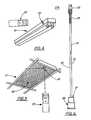
- FIG. 4is a perspective view of a strip fluorescent fixture including the present invention.
- FIG. 5is a perspective view of a troffer fluorescent fixture including the present invention.
- FIG. 6is a top view of the cable assembly according to the present invention.
- FIG. 7is a perspective view of a troffer fixture with the lens open illustrating the present invention.
- FIG. 8is a partial sectional view of the mounting of the cable assembly of the present invention in a troffer fixture.
- FIG. 9is an additional partial sectional view of the mounting of the cable assembly of the present invention in a troffer fixture.
- FIG. 10is a pictorial view of a strip fluorescent fixture, partially cut away, illustrating the present invention.
- FIG. 11is a sectional view of the detector housing according to the present invention.
- FIG. 12is a pictorial of the detector housing of FIG. 11.
- FIG. 13is an elevational view of the detector housing of FIG. 11.
- FIG. 14is a sectional view of the detector housing of FIG. 13, taken on line AA.
- FIG. 15is a plan view of the lens cover for the detector housing of FIG. 11.
- FIGS. 1, 4, 5 , 7 and 10the invention is illustrated in the context of a conventional fluorescent lamp (whether a strip fixture 10 or a troffer fixture 12 ), including an emergency ballast 14 for standby lighting during a period when the main AC power fails.
- FIG. 1illustrates the circuit diagram of a conventional emergency ballast which would be connected in parallel with a conventional fluorescent ballast 16 for providing emergency lighting in the event of main AC power failure.
- the standard fluorescent ballastbe shown, its output would be connected to lamp(s) LAMP, in parallel with the output of the emergency ballast EMERG.
- Relay contacts K 2 and K 3 operated by coils K 2 and K 3are responsive to the battery BATT charging current and upon failure of the main AC power, failure of power to the battery charging circuit In, and thus K 2 and K 3 , allows the switching of the relay contacts K 2 , K 3 , to shift the load of LAMP from the AC supply (via the standard ballast) to the emergency ballast EMERG. More particularly, as described below input/charging circuit In which provides charging current to the battery BATT and disables the emergency operation mode of the emergency ballast EMERG during the period that AC power is being supplied by main AC supply, as at J 11 or J 12 and J 13 .
- emergency ballastsinclusion of alternative voltage connections enable the system to be selectively connected to either standard commercial voltage AC (277 volts AC) or normal residential voltage (120 volts AC).
- Common, or ground potential connector J 13completes the connections to the system input.
- the two voltage terminals and the common terminalare connected to the AC inputs of a full wave (preferably) rectifier D 6 , the high voltage input terminal being connected via capacitors C 1 and C 4 and resistors R 8 and R 7 to limit the charging current supplied to rectifier D 6 to discharge the power from the capacitors after the power is removed from the circuits.
- the DC output from rectifier D 6is supplied to battery BATT via the coils of relays K 1 , K 2 and K 3 .
- the DC output of rectifier D 6is connected to a light emitting diode LED as an indicator that the battery BATT is in the charging mode.
- Relay K 3has a similar switch and associated set of contacts which are provided to connect load LAMP when the normal AC supply or auxiliary AC supply is powering the input/charging circuit In.
- Battery BATTmay be composed of, for example, a 6 volt (DC) nickel cadmium battery. Alternate battery configurations are possible, dictated by the power requirements of load LAMP.
- the output circuit O of the emergency ballast EMERGincludes a transformer T 1 having a primary winding P 1 and a feedback winding F 1 on the input side of transformer T 1 and a secondary winding S 1 on the output side. Output circuit O provides current limiting to the fluorescent lamp load LAMP only to the degree that is necessary to keep the lamp within its operational limits.
- the output circuit Ois composed of a capacitor, C 5 , connected across the output of the secondary winding, S 1 , of transformer T 1 . Capacitors C 6 and C 7 connected in parallel and generally in series with the fluorescent lamp LAMP which the output circuit O powers during emergency operation.
- inverter circuit IvIn the emergency mode, power is supplied to load LAMP from the output circuit by battery BATT through the operation of inverter circuit Iv. Initially the operation of the inverter circuit Iv is placed in operation by transistor Q 3 going into conduction enabling the oscillation of switching transistors Q 1 and Q 2 , including a high voltage surge from the output circuit O for a short interval (which may be in the order of a few milliseconds) after AC power failure to permit the starting of the fluorescent lamp. Those familiar with fluorescent lighting will recognize that a short application of an initial voltage in the range of approximately 500 volts is required to initiate the ignition of the gasses in the standard fluorescent lamp.
- Remote Control Test Circuitis connected to the emergency ballast EMERG through terminal J 1 - 6 , which is tied to the output of rectifier D 6 at diode D 1 .
- the output on pin GPO on microcontroller MC of the RCTactivates swithc Q 201 which sinks the current coming out of rectifier D 6 through resistor R 2 causing the battery charging circuit In to sense a failure of main AC power.
- the emergency ballast EMERGcycles through a 30 second or a 90 minute test, as signaled by the RCT.
- RCTis driven by a microcontroller chip MC, such as the PIC12C508 from Microchip, Inc. which is utilized in the illustrated embodiment.
- MCmicrocontroller chip
- the selection of a particular microprocessoris influenced by the functions to be performed, costs and compatibility with the other system components, and other microcontrollers might be selected, with some adjustment of other circuit components.
- RCTis powered by emergency ballast EMERG through contacts J 1 - 1 from battery BATT which is provided to regulator U 201 which provides a regulated 5 volt supply to the microcontroller chip MC and to an infrared detector ID, which is mounted on the face of a fluorescent fixture or, in the case of a ceiling mount with a translucent cover, on the face of the cover adjacent the fixture behind the cover (not shown).
- Infrared detector IDreceives a coded signal (described later) from the remote transmitter which is supplied to the base of buffer Q 202 which inverts and amplifies the received coded signal and inputs the signal to the microcontroller MC at pin GP 1 .
- Microcontrolleris driven by resonator RES, which in the illustrated embodiment includes capacitors C 206 and C 205 , R 205 and resonator Y 201 which sets the clock frequency of microcontroller MC at 2 MHZ, a value coordinated to the signal received from infrared detector ID to be examined and processed by microcontroller MC.
- resonator RESwhich in the illustrated embodiment includes capacitors C 206 and C 205 , R 205 and resonator Y 201 which sets the clock frequency of microcontroller MC at 2 MHZ, a value coordinated to the signal received from infrared detector ID to be examined and processed by microcontroller MC.
- the clock valuemight be varied should a different coded signal or other operating parameter be chosen.
- a reset capabilityis supplied by a reset control RS including undervoltage sensing integrated circuit U 203 (such as MC34164).
- Reset RSmonitors the battery BATT voltage (the 5 volt output voltage of regulator U 201 ) and is set to signal a supply voltage of less than 2.7 volts, selected as the lower limit of reliability for signal processing by microcontroller MC. On observation of a supply voltage of below 2.7 volts, reset RS provides an input to microcontroller MC pin MCLR which in the preferred embodiment illustrated disables the microcontroller MC.
- reset RSWhen reset RS observes that the supply voltage has returned (i.e., above 2.7 volts), it outputs a signal through resistor R 204 to pin VDD to recycle or “wake up” the microcontroller MC such that any incoming signals from infrared detector ID may be again processed.
- FIG. 2illustrates the interrogating signals transmitted by the hand-held remote (not shown) which are received by the infrared detector ID ( 20 in FIGS. 4, 5, 7 , 8 , 9 , 10 and 11 ).
- This carrieris amplitude modulated by a 38 KHz sub carrier in digital (on-off) pulses. This type of modulation is termed Amplitude Shift Keying modulation and significantly reduces the possibility of interference from other infrared sources, particularly the fluorescent lamps in close proximity to the testing process.
- the on-off digital pulsesform a code modulation method of Pulse Code modulation (PCM) and the series of pulses convey the information respecting to the particular test to be performed.
- PCMPulse Code modulation
- the signalincorporates a Pulse-Timing modulation (PTM) of a serial bit pulse train of nine bits, one start bit followed by eight data bits. These bits (again in this preferred embodiment) are 2.11 ms apart (at 473.9 Hz) with an “ON” pulse width of 0.817 ms, yielding a duty cycle of 38.7 percent.
- PTMPulse-Timing modulation
- the 9-bit cycleis followed by a break, in the preferred embodiment of 31.6 ms.
- the entire signal(data plus break) is repeated every 49.27 ms as long as a selected transmit key on the hand-held remote is activated. It is significant to the reliability and repeatability of the inventive test that the complexity of both Pulse Code and Pulse Timing modulation are combined, the effect of which is to increase the signal-to-noise ratio of the interrogation to ensure accuracy and reliability of test.
- the described approachincluding a microcontroller in combination with the infrared detector to decode the test signal, the use of expensive and massive “matched filter” is otherwise avoided.
- FIG. 3illustrates three different signal lines, one for the 30 second test wherein the emergency ballast is signaled on for the 30 second period to assure operation of the fluorescent lamp in that period.
- the second signal lineinitiates the 90 minute test wherein the emergency ballast is controlled in the on condition for a period of 90 minutes to verify that the emergency lighting (and the battery capacity) will continue lighting in the emergency mode for that period.
- the third signalis to provide a reset of the system (and the emergency ballast) back to the regular operating condition wherein the lighting is powered by the main AC supply through the standard ballast, and the emergency ballast is in standby condition with its battery being charged.
- the reset signalis used primarily to terminate a running test, should that be desired.
- the microcontrollerclock times each test and terminates the procedure at the end of the requisite time (i.e., 30 seconds or 90 minutes.)
- the hand-held remote control transmitteris analogous to the remote controls for television and video recorders, however wherein a preprogramed IC selectively transmits the signal pulse words illustrated in FIG. 3 according to the activation of the operating switches located on the hand-held control.
- the preferred hand-held controlincludes the capacity to selectively transmit one of the three pulse-time signals, each of which is dedicated to one of the three command functions of the hand-held remote: a) the 30 second test; b) the 90 minute test; and c) the reset signal.
- the transmitteris aimed at the detector ID ( 18 in FIGS. 4, 5) in the fluorescent fixture ( 10 , 12 in FIGS. 4, 5), such that the selected infrared pulse train is beamed at the detector housing 20 .
- the signalUpon receipt of the signal, it is processed as described above.
- inventive signal code and timing together with the inventive elements described belowenable the effective use of relative inexpensive, easily installed and used infrared signal interrogation and decoding within a high infrared noise environment and electromagnetic fields, thereby enabling the use of low cost infrared remote technology analogous to that used in TV's and VCR's, which otherwise would be unusable.
- inventive detector housing 20 and shielded cable assembly 23enable the more reliable use of the infrared signal code and timing in the noisy infrared environment.
- this start bitis recognized as a correct bit, then the remaining eight bits are checked for the correct “ON” and “OFF” times, or are read and identified as one of the three signal train streams.
- the microcontrollerlooks for a second stream of bit information, to verify it as correct and a match of the first signal stream.
- the signal interrogationis checked for correctness in format based upon time, duty cycle and matching (twice) one of the three coded patterns.
- the inventive methodologyprovides sufficient signal-to-noise response to prevent false triggering of the test procedure by random infrared noise signals.
- the microcontroller clockis cleared, ready for the start of the interrogation process.
- the software in the microcontrollersets up the memory map and counters to prepare the sequence of functions to be performed by the controller.
- CLEARsets the status register.
- CHECKis a verification that the microcontroller is set up and keeps up with time after which it SCANs the signal from the infrared detector ID to verify the receiving signal is at the required voltage level for processing; if it is (GP1 HIGH) the processing continues, if not, the microcontroller continues to examine incoming signals to look for one of the requisite voltage.
- COLLECT START BIT DATAreceives the first data bit which in GOOD START BIT is checked for proper timing and width, and if the criteria are met (yes) the processing continues. If the start bit fails, the microcontroller resumes looking for a proper signal, clearing all stored signal memory at CLEAR. Once the suitable start bit is recognized, the microcontroller at COLLECT BODY DATA receives the remainder (8 bits) of the signal and examines the string to verify (CHECK) that eight additional bits were received. The microcontroller then in DECIFER does a more detailed review of the signal string to verify that the first bit is a true first bit (time and pulse width) and (CHECK) that there are eight correct following bits.
- BODY OF WORD GOODis the second check on the following string of data bits to verify that the examined signal was repeated and matched. If this WORD is matched to one of the three words, the microprocessor then (on yes) proceeds to the test; if not, the process goes back to the CLEAR, clearing out stored signal memory and looking again for a proper first bit.
- the microcontrollerreads its activity to determine whether there is a test already ongoing; if so, the START ABORT function reads the word to see if it is the RESET signal, in which case the RUN ABORT SEQUENCE terminates the running test and sends the process back to the CLEAR function.
- the particular bit wordis examined to determine whether a 30 second or a ninety minute test is called for.
- the 30 SECOND TEST or the 90 MINUTE TESTinitiates the appropriate test sequence, including TURN LAMP ON for the requisite period and after the running of the program, or the abort sequence, the microcontroller returns to CLEAR for another signal.
- one important objective of the present inventionis to allow the technician to aim the Remote Control Transmitter 22 (FIGS. 4 and 5) toward the lighting fixture 10 , 12 and energize the test routine preferred.
- the detector and the wires connecting the infrared detector to the Remote Control Test Circuit(RCT in FIG. 1) must be placed totally within the fixture or, run through electrical conduit (which is costly, and would be cumbersome in installation). Therefore, placement of an infrared detector housing 20 must be behind the fixture lens 24 (troffer fixture 12 in FIGS. 5 and 7).
- infrared remote controllersare not utilized in close proximity to fluorescent lighting.
- the detectoris located behind fixture lens 24 (the function of which is to diffuse the fluorescent light generated) so the fixture lens 24 further diffuses the signal from the Remote Control Transmitter 22 before it is received by the detector 18 in detector housing 20 as well as reflecting some of the infrared noise generated by the fluorescent light back toward the detector 18 .
- a further factor complicating the use of infrared detectors in such as fluorescent lightingis the electromagnetic fields generated by the high frequency electronic conventional 16 and emergency ballasts 14 which are in close proximity to a detector housing 20 mounted within a light fixture 10 , 12 .
- the present inventionenables the use of infrared remote controllers in fields having a high degree of infrared noise, even when associated components generate electromagnetic fields, techniques previously avoided by those skilled in the art.
- the present inventionincludes a novel detector housing 20 in which an infrared detector unit 18 , such as a GP1U901X infrared detector from Sharp Electronics, Inc., is mounted.
- the preferred detectoris compact in size to be conveniently located within the flourescent fixture 10 , 12 .
- Detector 18is mounted in a housing 20 which is also sized to be conveniently placed within a fluorescent fixture.
- detector housing 20is comprised of two adjoining cylindrical sections, a collar section 21 and a detector section 28 .
- collar sectionBeing adapted for mounting directly into standard fixtures as strip 10 and troffer 12 , collar section is approximately 1 ⁇ 2 inch in diameter to fit a standard 1 ⁇ 2 inch electrical mounting tube 26 for the troffer mounting illustrated in FIG. 8 and 9 .
- Tube 26is retained in fixture 12 by means such as bracket 19 conveniently located near the end of fixture as illustrated in FIG. 5.
- the detector section 28For mounting in a strip fixture 10 having standard 5 ⁇ 8 inch holes, the detector section 28 has an outside diameter of approximately 5 ⁇ 8 inch.
- Housing 20is manufactured of a convenient, light weight material such as PVC, either by fabrication or molding. Other materials, including metals might be substituted, depending upon cost of materials and manufacture.
- the preferred detector 18is capable of receiving the interrogating signals from the Remote Control Transmitter 22 and generating a comparable signal which is passed on to the remote control test circuit (RCT in FIG. 1) which is physically located in the emergency ballast 14 .
- Detector 18operates on the Amplitude Shift Keying (ASK) code principle and incorporates a 38 kHz bandpass filter with high-gain amplifiers and an automatic gain control (AGC), parameters matching the interrogating signal from the Remote Control Transmitter 22 .
- AGCautomatic gain control
- Contributing to the special effectiveness of the present inventionis the configuration of the detector housing 20 . As may be seen in FIGS. 12 through 15, housing 20 includes collar section 21 sized to conveniently receive cable 27 which connects detector 18 to the remote control test circuit RCT (FIG. 1).
- Cable 27is preferably shielded to minimize electromagnetic induction from the fields established by the conventional and emergency ballasts. Further, cable 27 is sealed into the inside diameter 25 of collar 21 with potting 31 , such as a silicon compound, for strain relief between the cable and collar section internal diameter 25 . Detector 18 is mounted into the detector section 28 of housing 20 , being affixed with a suitable adhesive to a mounting platform such as the off-set 30 between the different inside diameters 29 , 25 of the collar section 21 and the detector section 28 , respectively.
- potting 31such as a silicon compound
- An additional aspect of the present inventionincludes shielding 34 around the interior diameter 29 of the detector section 28 .
- Shielding 34is of an electrically conductive material, such as an adhesive backed copper tape such as produced by Minnesota Mining and Manufacturing, Inc. and available from electrical supply houses. Other shielding materials may be used so long as they are attachable to the interior diameter of detector section 28 .
- shielding 34is connected at terminal 36 to the ground wire 27 d for cable 27 which is also shielded (not shown) and similarly connected to detector housing 20 at terminal 37 to protect against the electromagnetic field established by and in the vicinity of the electronic ballasts for the fluorescent lamps.
- the Sharp GPIU901Xis enclosed in a metal case or housing 18 h so that the detector 18 electronics are also shielded from the electromagnetic field of the ballasts. Since both housing 20 and cable 27 are shielded against the electromagnetic field interference, both may be mounted within the body of lighting fixtures 10 , 12 .
- the lens cover 46Completing the assembly of detector housing 20 is the lens cover 46 which covers and protects the sensitive infrared detector 18 from dust or other airborne particles which may be present in a commercial or industrial environment.
- Lens cover 46is preferably white so as to be relatively unnoticeable under fixture lens 24 when closed.
- Cover 46is composed of a material which is translucent or transparent to the infrared signal from remote control 22 , such as of a rigid vinyl or MYLAR, a polyester material available from E. I. duPont de Nemours & Company. Lens cover 46 material is selected to provide minimal attenuation of the infrared test initiating signal from Remote Control Transmitter since the less attenuation caused by lens cover 46 , the greater will be the strength of the test initiating signal which must be received through the infrared noise by detector eye 32 . Lens cover 36 is retained on detector section 28 by means such as an adhesive or other suitable attachment mechanism.
- cable assembly 23(FIG. 6) including cable 27 being a three wire shielded cable such as Belden 9533 060 which is fitted at one end with a miniaturized, three prong plug-type connector 33 such as Berg 67954-002. It is preferable to enclose the connector 33 and attached (as by soldering or crimping) wires 27 r, 27 w, and 27 b in such as stress relieving sleeve 35 , (i.e, heat shrink tubing from SPC Technology PHS-024) to ensure reliable performance. Cable assembly 23 is terminated at its other end by detector housing 20 including detector 18 .
- Cable wires 27 r and 27 wterminate on terminals 37 t of detector 18 and carry the signal output of detector 18 responsive to Remote Control Transmitter 22 test signals to the remote control test circuit RCT (illustrated in FIG. 1).
- Wire 27 b and the cable shield drain 27 dare terminated on the casing 18 h of detector 18 at terminal 37 and drain 27 d is also terminated on detector shield 34 at terminal 6 (all illustrated in FIG. 11).
- the termination of wires 27 r and 27 w at detector 18includes stress relieving sleeve 38 , preferably of such as heat shrink tubing (e.g., 3M FP301).
- emergency ballast 14with a complementary cable assemble 23 ′(to assembly 23 ) which is connected to the test circuit RCT (FIG. 1), and a cooperating female plug 33 ′(e.g., Berg 67954-00) to plug 33 so that the cables 23 , 23 ′ need only to be connected, as at connection 40 in FIG. 9.
- RCTtest circuit
- cooperating female plug 33 ′e.g., Berg 67954-00
- the following componentshave the values indicated: C1 6.8 ⁇ Fd C4 4.7 ⁇ Fd C5 220 ⁇ Fd C6 1000 ⁇ Fd C7 680 ⁇ Fd C8 1500 ⁇ Fd C20 4.7 ⁇ Fd C201 0.1 ⁇ Fd. C202 0.1 ⁇ Fd. C203 15 ⁇ Fd. TANT C204 0.1 ⁇ Fd. Q1 NPN transistor D44H8 Q2 NPN transistor D44H8 Q3 PNP transistor 2N4403 PNP Q201 NPN transistor ZTX851 Q202 NPN transistor ZTX851 U201 Regulator 5V.
- T Transformer S1 500turns, 34 ga. P1, 6 turns, center tapped, 23 ga. F1 2 turns, 23 ga. Core ferrite plus BATT Battery NiCd, SAFT, 6V, 4000 mAh LED Indicator red ID Infrared Detector Sharp GPIU901X 10 Strip fixture 12 Troffer fixture 14 Emergency ballast 16 Conventional ballast 18 Detector 18h Conductive case 19 Mounting bracket 20 Detector housing 22 Remote Control Transmitter 23 Cable assembly 23′ Cable assembly 24 Fixture lens 25 Collar section inside diameter 26 Electrical mounting tube 27 Cable 27r red cable wire 27w White cable wire 27d Drain wire 28 Detector section 29 Detector section inside diameter 30 Off set 31 Potting 32 Detector eye 33 Cable plug 33′ Cable plug 34 Detector shield 35 Stress relieving sleeve 36 Detector/drain terminal 37 Shield/drain connection 38 Stress relieving sleeve 40 Connection
- the inventive signaling systemmay be utilized for other desirable control functions in an infrared/high EMI field environment, including functions as a switch for activating the standard fluorescent lamp.
Landscapes
- Business, Economics & Management (AREA)
- Emergency Management (AREA)
- Engineering & Computer Science (AREA)
- Power Engineering (AREA)
- Circuit Arrangement For Electric Light Sources In General (AREA)
- Selective Calling Equipment (AREA)
Abstract
Description
- This application claims priority of U.S. Provisional Application Ser. No. 60/106,470, filed Oct. 30, 1998, and is a division of U.S. Application Ser. No. 09/428,898, filed Oct. 28, 1999.[0001]
- [0002] Not Applicable
- 1. Field of the Invention[0003]
- The invention relates to emergency lighting, and particularly to fluorescent lighting wherein a ballast for a fluorescent lamp is connected to a source of electrical energy other than normal AC line current in the event that the normal AC current fails.[0004]
- Emergency lighting is required in commercial, industrial, and institutional buildings just as fire extinguishers, smoke alarms and other safety equipment. Three types of emergency lighting are common in such installations: unit equipment, engine generators and central battery systems. Unit equipment falls into two principle types: fluorescent and incandescent.[0005]
- The fluorescent units are customarily combined with and within a conventional fluorescent lighting unit by merely adding the emergency ballast consisting of a battery, a battery charger, inverter and sensing circuitry adjacent the standard fluorescent ballast. The sensing circuit observes the interruption of normal AC power to the lamp unit and immediately switches on the emergency ballast which powers the light fixture for the required period which, under most state safety codes, is a period of at least ninety (90) minutes, a standard called out in the National Electrical Code, NFPA Article 70, and NFPA Article 101 Life Safety Code. These regulations at NFPA, Article 101, Section 5-9.3 also mandate that periodic monitoring of the ready status of the emergency systems, including a 30 day test requiring 30 seconds of lighting and annual test requiring a 90 minute duration of lighting. An exception is provided for those emergency lighting units which contain a self testing/self-diagnostic circuit which automatically performs a minimum 30 second test and diagnostic routine at least once every 30 days and indicates failures by a status indicator. U.S. Pat. No. 5,666,029 assigned to the assignee of the present invention is illustrative of such a self testing/self diagnostic circuit.[0006]
- 2. General Background of the Invention[0007]
- U.S. Pat. No. 5,004,953 entitled Emergency Lighting Ballast for Compact Fluorescent Lamps with Integral Starters, assigned to the assignee of the present invention is illustrative of the fluorescent type of emergency lighting with a ballast. It is common in the installation of emergency fluorescent lighting that an emergency ballast is added to a conventional fluorescent fixture either in original installation or by retrofit. Alternatively, emergency lighting may be provided integrally in a unit having both internal regular and emergency ballasts installed. When main AC power to the lighting fails, voltage sensing circuitry instantly connects DC current from a battery (in the emergency ballast) to an inverter which produces high frequency, high voltage power to illuminate the emergency fluorescent lamp(s) for the required period.[0008]
- The inclusion of test circuits for emergency fluorescent lighting is common, typically including the Test/Monitor panel, either mounted on a wall in the building, generally adjacent the emergency lamp, or on the case of the fluorescent ballast or fixture. The operation of these types of testing circuits requires the technician to go to the particular location of the test switch for each emergency fixture, which is somewhat time consuming. Such a configuration involves considerable installation cost in that the wall mounted test switch must be wired directly to each fixture to be tested. In the case of test switches located directly on a fixture, though avoiding the extra installation cost of the wall mounted switch, the technician then has to access each fixture individually to initiate the test. This procedure is time consuming since fixtures are often eight to twenty feet above the floor in commercial or industrial buildings.[0009]
- U.S. Pat. No. 5,666,029 entitled Fluorescent Emergency Ballast Self Test Circuit, assigned to the assignee of the present invention is illustrative of a fluorescent emergency lighting ballast which includes an integral self test function. In the described ballast, the testing is a programmed function, carried out independently by the circuitry in the ballast and in the event of a malfunction in the test, a warning light and/or alarm sounds to advise of the test malfunction.[0010]
- The present invention in its most common form involves the combination of the concept of a type of remote control as utilized with garage door openers, television and VCR machines which activates a specialized monitor circuit integrally connected into the emergency ballast for the fluorescent emergency lamp. With this remote control test feature, a technician performing the tests, whether the 30 second or the 90 minute variety, may conduct a survey of several emergency fixtures in a “point-click-test” series while making a tour through a facility, returning within the required time frame (30 seconds or 90 minutes) to observe that the lamp is still operating in the emergency mode and meeting the requirements of the Life Safety Code. In a preferred embodiment, the test unit includes a reset function to terminate any unwanted prior test activation. On reset, any prior test of the emergency ballast to emergency (i.e., battery) function is terminated and the lamp is reconnected to normal AC power, with the battery charging circuit also energized.[0011]
- Prior attempts of providing fluorescent emergency lighting with such remote control operation have been unsuccessful. The significant amounts of infrared light (noise) produced by fluorescent lamps interferes with conventional remote control transmitters and receivers, to the degree that reliable, repeatable tests have not been possible. Further, the significant amount of infrared noise within the flourescent fixture has prevented the mounting of a useful detector of the remote test control signal. The present invention breaks through the infrared noise barrier by using a uniquely coded signal which interrogates the fixture and if analyzed to be of a proper digital pulse train, and upon successful match, initiates the particular requested test sequence (30 second or 90 minute). The invention further provides a novel infrared detector housing further enhancing the receipt of the coded signal and novel cabling to connect the detector to the control circuit in the emergency ballast.[0012]
- It is an object of the present invention to perform selective testing of an emergency ballast of a fluorescent luminaire.[0013]
- A collateral object of the invention is to perform testing in the emergency ballast which closely simulates the emergency function of the luminaire, verifying that the emergency capacity of the luminaire is functional.[0014]
- A further object of the invention is to provide for remote activation of the emergency test without having to activate a test switch located on the luminaire or at a discrete location.[0015]
- These and other objects of the present invention are achieved by a lighting system including a luminaire including a fluorescent lamp, means for delivering main AC power to the lamp from an AC power source; a DC power source consisting of a stored energy supply; rectifier means for recharging the stored energy supply; inverter means connected to the stored energy supply for producing power from current provided by the DC power supply; supplying such power to the lamp when the mains AC power is interrupted and means for deactivating the inverter when main AC power is being supplied to the lamp; a remote infrared transmitter capable of emitting a coded signal for interrogating an emergency ballast test control; an infrared detector coupled to a microcontroller through a quick connect shielded cable to receive, examine and decode the coded signal, the microcontroller signaling the emergency ballast to supply power from the stored energy source by switching off the mains AC power upon recognition of the coded test signal.[0016]
- FIG. 1 is a circuit diagram of a preferred embodiment of the remote control test for fluorescent emergency lighting according to the present invention including the infrared initiated microcontroller circuit for activating a remote control test.[0017]
- FIG. 2 is a flow chart illustrating the test procedure according to the present invention.[0018]
- FIG. 3 is a diagram of the code signal transmitted by the remote control transmitter and received and processed by the microcontroller circuit in the present invention.[0019]
- FIG. 4 is a perspective view of a strip fluorescent fixture including the present invention.[0020]
- FIG. 5 is a perspective view of a troffer fluorescent fixture including the present invention.[0021]
- FIG. 6 is a top view of the cable assembly according to the present invention.[0022]
- FIG. 7 is a perspective view of a troffer fixture with the lens open illustrating the present invention.[0023]
- FIG. 8 is a partial sectional view of the mounting of the cable assembly of the present invention in a troffer fixture.[0024]
- FIG. 9 is an additional partial sectional view of the mounting of the cable assembly of the present invention in a troffer fixture.[0025]
- FIG. 10 is a pictorial view of a strip fluorescent fixture, partially cut away, illustrating the present invention.[0026]
- FIG. 11 is a sectional view of the detector housing according to the present invention.[0027]
- FIG. 12 is a pictorial of the detector housing of FIG. 11.[0028]
- FIG. 13 is an elevational view of the detector housing of FIG. 11.[0029]
- FIG. 14 is a sectional view of the detector housing of FIG. 13, taken on line AA.[0030]
- FIG. 15 is a plan view of the lens cover for the detector housing of FIG. 11.[0031]
- Referring now to FIGS. 1, 4,[0032]5,7 and10, the invention is illustrated in the context of a conventional fluorescent lamp (whether a
strip fixture 10 or a troffer fixture12), including anemergency ballast 14 for standby lighting during a period when the main AC power fails. FIG. 1 illustrates the circuit diagram of a conventional emergency ballast which would be connected in parallel with a conventionalfluorescent ballast 16 for providing emergency lighting in the event of main AC power failure. In the FIG. 1, were the standard fluorescent ballast be shown, its output would be connected to lamp(s) LAMP, in parallel with the output of the emergency ballast EMERG. Relay contacts K2 and K3 operated by coils K2 and K3 are responsive to the battery BATT charging current and upon failure of the main AC power, failure of power to the battery charging circuit In, and thus K2 and K3, allows the switching of the relay contacts K2, K3, to shift the load of LAMP from the AC supply (via the standard ballast) to the emergency ballast EMERG. More particularly, as described below input/charging circuit In which provides charging current to the battery BATT and disables the emergency operation mode of the emergency ballast EMERG during the period that AC power is being supplied by main AC supply, as at J11 or J12 and J13. In preferred embodiments of emergency ballasts, inclusion of alternative voltage connections enable the system to be selectively connected to either standard commercial voltage AC (277 volts AC) or normal residential voltage (120 volts AC). Common, or ground potential connector J13 completes the connections to the system input. - The two voltage terminals and the common terminal are connected to the AC inputs of a full wave (preferably) rectifier D[0033]6, the high voltage input terminal being connected via capacitors C1 and C4 and resistors R8 and R7 to limit the charging current supplied to rectifier D6 to discharge the power from the capacitors after the power is removed from the circuits. The DC output from rectifier D6 is supplied to battery BATT via the coils of relays K1, K2 and K3. Similarly, the DC output of rectifier D6 is connected to a light emitting diode LED as an indicator that the battery BATT is in the charging mode.
- Responsive to the status of input/charging circuit In, the switch of relay, K[0034]2, which is connected to terminal J27, and to a normally open contact (NO) of relay, K2, when its coil is energized and to terminal J25, a normally closed contact (NC) of relay K2 when its coil is de-energized, the latter position being that illustrated in FIG. 1. Relay K3 has a similar switch and associated set of contacts which are provided to connect load LAMP when the normal AC supply or auxiliary AC supply is powering the input/charging circuit In.
- Battery BATT may be composed of, for example, a 6 volt (DC) nickel cadmium battery. Alternate battery configurations are possible, dictated by the power requirements of load LAMP. The output circuit O of the emergency ballast EMERG includes a transformer T[0035]1 having a primary winding P1 and a feedback winding F1 on the input side of transformer T1 and a secondary winding S1 on the output side. Output circuit O provides current limiting to the fluorescent lamp load LAMP only to the degree that is necessary to keep the lamp within its operational limits. The output circuit O is composed of a capacitor, C5, connected across the output of the secondary winding, S1, of transformer T1. Capacitors C6 and C7 connected in parallel and generally in series with the fluorescent lamp LAMP which the output circuit O powers during emergency operation.
- In the emergency mode, power is supplied to load LAMP from the output circuit by battery BATT through the operation of inverter circuit Iv. Initially the operation of the inverter circuit Iv is placed in operation by transistor Q[0036]3 going into conduction enabling the oscillation of switching transistors Q1 and Q2, including a high voltage surge from the output circuit O for a short interval (which may be in the order of a few milliseconds) after AC power failure to permit the starting of the fluorescent lamp. Those familiar with fluorescent lighting will recognize that a short application of an initial voltage in the range of approximately 500 volts is required to initiate the ignition of the gasses in the standard fluorescent lamp. Immediately after ignition, as switch Q3 continues to supply base current to Q1 and Q2 as later discussed, the current regulating capacitors C8 and C7 in the output circuit O regulate the current level to that required to operate the fluorescent lamp at its emergency rated (reduced) illumination.
- During normal operation when main AC power supply is functioning, charging current is supplied from the rectifier D[0037]6, to battery BATT, while energizing relays K1 and K2 so that the switch Q3 and the oscillating switches Q1 and Q2 and the output circuit O are inactive. Should the main AC power supply fail, and for that continuing period of time until normal main AC power resumes, such that its frequency and voltage output again power rectifier D6, relays K1 and K2 are de-energized so that the fluorescent lamp load is connected to the output circuit O and the inverter Iv is triggered into operation.
- Remote Control Test Circuit (RCT) is connected to the emergency ballast EMERG through terminal J[0038]1-6, which is tied to the output of rectifier D6 at diode D1. In order to initiate a test of the function of the emergency ballast, the output on pin GPO on microcontroller MC of the RCT activates swithc Q201 which sinks the current coming out of rectifier D6 through resistor R2 causing the battery charging circuit In to sense a failure of main AC power. Then, according the description of the RCT circuit below, the emergency ballast EMERG cycles through a 30 second or a 90 minute test, as signaled by the RCT.
- As illustrated in FIG. 1, RCT is driven by a microcontroller chip MC, such as the PIC12C508 from Microchip, Inc. which is utilized in the illustrated embodiment. As those skilled in the art will appreciate, the selection of a particular microprocessor is influenced by the functions to be performed, costs and compatibility with the other system components, and other microcontrollers might be selected, with some adjustment of other circuit components. RCT is powered by emergency ballast EMERG through contacts J[0039]1-1 from battery BATT which is provided to regulator U201 which provides a regulated 5 volt supply to the microcontroller chip MC and to an infrared detector ID, which is mounted on the face of a fluorescent fixture or, in the case of a ceiling mount with a translucent cover, on the face of the cover adjacent the fixture behind the cover (not shown). Infrared detector ID receives a coded signal (described later) from the remote transmitter which is supplied to the base of buffer Q202 which inverts and amplifies the received coded signal and inputs the signal to the microcontroller MC at pin GP1. Microcontroller is driven by resonator RES, which in the illustrated embodiment includes capacitors C206 and C205,
R 205 and resonator Y201 which sets the clock frequency of microcontroller MC at 2 MHZ, a value coordinated to the signal received from infrared detector ID to be examined and processed by microcontroller MC. As observed previously, those skilled in the art should understand that the clock value might be varied should a different coded signal or other operating parameter be chosen. - As added reliability for the testing process available through the remote control test circuit RCT, a reset capability is supplied by a reset control RS including undervoltage sensing integrated circuit U[0040]203 (such as MC34164). Reset RS monitors the battery BATT voltage (the 5 volt output voltage of regulator U201) and is set to signal a supply voltage of less than 2.7 volts, selected as the lower limit of reliability for signal processing by microcontroller MC. On observation of a supply voltage of below 2.7 volts, reset RS provides an input to microcontroller MC pin MCLR which in the preferred embodiment illustrated disables the microcontroller MC. When reset RS observes that the supply voltage has returned (i.e., above 2.7 volts), it outputs a signal through resistor R204 to pin VDD to recycle or “wake up” the microcontroller MC such that any incoming signals from infrared detector ID may be again processed.
- FIG. 2 illustrates the interrogating signals transmitted by the hand-held remote (not shown) which are received by the infrared detector ID ([0041]20 in FIGS. 4, 5,7,8,9,10 and11). The carrier frequency for the remote communications is centered at 319 THz, which is in the infrared spectrum (λ=950 nm). This carrier is amplitude modulated by a 38 KHz sub carrier in digital (on-off) pulses. This type of modulation is termed Amplitude Shift Keying modulation and significantly reduces the possibility of interference from other infrared sources, particularly the fluorescent lamps in close proximity to the testing process. The on-off digital pulses form a code modulation method of Pulse Code modulation (PCM) and the series of pulses convey the information respecting to the particular test to be performed. In the preferred embodiment illustrates, the signal incorporates a Pulse-Timing modulation (PTM) of a serial bit pulse train of nine bits, one start bit followed by eight data bits. These bits (again in this preferred embodiment) are 2.11 ms apart (at 473.9 Hz) with an “ON” pulse width of 0.817 ms, yielding a duty cycle of 38.7 percent. The 9-bit cycle is followed by a break, in the preferred embodiment of 31.6 ms. Accordingly, the entire signal (data plus break) is repeated every 49.27 ms as long as a selected transmit key on the hand-held remote is activated. It is significant to the reliability and repeatability of the inventive test that the complexity of both Pulse Code and Pulse Timing modulation are combined, the effect of which is to increase the signal-to-noise ratio of the interrogation to ensure accuracy and reliability of test. By using the described approach including a microcontroller in combination with the infrared detector to decode the test signal, the use of expensive and massive “matched filter” is otherwise avoided. Further, the use of the low frequency bit rate enables the signal to be checked for time “on” as well as time “off”, along with the check of the bit pattern correctness, all without excessive demands on the decoding and thus reducing cost of the circuit. FIG. 3 illustrates three different signal lines, one for the 30 second test wherein the emergency ballast is signaled on for the 30 second period to assure operation of the fluorescent lamp in that period. The second signal line initiates the 90 minute test wherein the emergency ballast is controlled in the on condition for a period of 90 minutes to verify that the emergency lighting (and the battery capacity) will continue lighting in the emergency mode for that period. The third signal is to provide a reset of the system (and the emergency ballast) back to the regular operating condition wherein the lighting is powered by the main AC supply through the standard ballast, and the emergency ballast is in standby condition with its battery being charged. The reset signal is used primarily to terminate a running test, should that be desired. The microcontroller clock times each test and terminates the procedure at the end of the requisite time (i.e., 30 seconds or 90 minutes.) The hand-held remote control transmitter is analogous to the remote controls for television and video recorders, however wherein a preprogramed IC selectively transmits the signal pulse words illustrated in FIG. 3 according to the activation of the operating switches located on the hand-held control. The preferred hand-held control includes the capacity to selectively transmit one of the three pulse-time signals, each of which is dedicated to one of the three command functions of the hand-held remote: a) the 30 second test; b) the 90 minute test; and c) the reset signal. Similarly to the television remote, the transmitter is aimed at the detector ID (18 in FIGS. 4, 5) in the fluorescent fixture (10,12 in FIGS. 4, 5), such that the selected infrared pulse train is beamed at the
detector housing 20. Upon receipt of the signal, it is processed as described above. - The inventive signal code and timing together with the inventive elements described below enable the effective use of relative inexpensive, easily installed and used infrared signal interrogation and decoding within a high infrared noise environment and electromagnetic fields, thereby enabling the use of low cost infrared remote technology analogous to that used in TV's and VCR's, which otherwise would be unusable. The[0042]
inventive detector housing 20 and shieldedcable assembly 23 enable the more reliable use of the infrared signal code and timing in the noisy infrared environment. By way of general explanation of the interrogation process, prior to the full explanation of the flow diagram of FIG. 3, in the process of interrogation, the start bit is checked for a correct “ON” time and then checked for a correct “OFF” time. If this start bit is recognized as a correct bit, then the remaining eight bits are checked for the correct “ON” and “OFF” times, or are read and identified as one of the three signal train streams. Once the decoded pattern is verified as one of the three proper signals, the microcontroller looks for a second stream of bit information, to verify it as correct and a match of the first signal stream. Thus, the signal interrogation is checked for correctness in format based upon time, duty cycle and matching (twice) one of the three coded patterns. The inventive methodology provides sufficient signal-to-noise response to prevent false triggering of the test procedure by random infrared noise signals. - As illustrated in the flowchart of FIG. 2, on START, the microcontroller clock is cleared, ready for the start of the interrogation process. On INITIALIZATION the software in the microcontroller sets up the memory map and counters to prepare the sequence of functions to be performed by the controller. When the memory map and counters are installed, CLEAR sets the status register. CHECK is a verification that the microcontroller is set up and keeps up with time after which it SCANs the signal from the infrared detector ID to verify the receiving signal is at the required voltage level for processing; if it is (GP1 HIGH) the processing continues, if not, the microcontroller continues to examine incoming signals to look for one of the requisite voltage. With the recognition of a signal of sufficient voltage, COLLECT START BIT DATA receives the first data bit which in GOOD START BIT is checked for proper timing and width, and if the criteria are met (yes) the processing continues. If the start bit fails, the microcontroller resumes looking for a proper signal, clearing all stored signal memory at CLEAR. Once the suitable start bit is recognized, the microcontroller at COLLECT BODY DATA receives the remainder (8 bits) of the signal and examines the string to verify (CHECK) that eight additional bits were received. The microcontroller then in DECIFER does a more detailed review of the signal string to verify that the first bit is a true first bit (time and pulse width) and (CHECK) that there are eight correct following bits. If the CHECK is passed, BODY OF WORD GOOD is the second check on the following string of data bits to verify that the examined signal was repeated and matched. If this WORD is matched to one of the three words, the microprocessor then (on yes) proceeds to the test; if not, the process goes back to the CLEAR, clearing out stored signal memory and looking again for a proper first bit. At TEST IN PROGRESS the microcontroller reads its activity to determine whether there is a test already ongoing; if so, the START ABORT function reads the word to see if it is the RESET signal, in which case the RUN ABORT SEQUENCE terminates the running test and sends the process back to the CLEAR function. With no test in progress, the particular bit word is examined to determine whether a 30 second or a ninety minute test is called for. On the particular recognition, either the 30 SECOND TEST or the 90 MINUTE TEST initiates the appropriate test sequence, including TURN LAMP ON for the requisite period and after the running of the program, or the abort sequence, the microcontroller returns to CLEAR for another signal.[0043]
- Referring now generally to FIGS. 4 through 15, one important objective of the present invention is to allow the technician to aim the Remote Control Transmitter[0044]22 (FIGS. 4 and 5) toward the
lighting fixture infrared detector housing 20 must be behind the fixture lens24 (troffer fixture 12 in FIGS. 5 and 7). It is well known to those skilled in the art relating to infrared remote controls such as for television and video recorders that fluorescent lighting generates significant infrared noise which interferes with the communication signals of infrared controllers. It is for this reason that infrared remote controllers are not utilized in close proximity to fluorescent lighting. There is an added complication in the present application since the detector is located behind fixture lens24 (the function of which is to diffuse the fluorescent light generated) so thefixture lens 24 further diffuses the signal from theRemote Control Transmitter 22 before it is received by thedetector 18 indetector housing 20 as well as reflecting some of the infrared noise generated by the fluorescent light back toward thedetector 18. A further factor complicating the use of infrared detectors in such as fluorescent lighting is the electromagnetic fields generated by the high frequency electronic conventional16 andemergency ballasts 14 which are in close proximity to adetector housing 20 mounted within alight fixture - Referring now specifically to FIGS. 4 through 15, in addition to the use of a specially coded signal which is verified by a second signal train as discussed above, the present invention includes a[0045]
novel detector housing 20 in which aninfrared detector unit 18, such as a GP1U901X infrared detector from Sharp Electronics, Inc., is mounted. The preferred detector is compact in size to be conveniently located within theflourescent fixture Detector 18 is mounted in ahousing 20 which is also sized to be conveniently placed within a fluorescent fixture. In the preferred embodiment illustrated,detector housing 20 is comprised of two adjoining cylindrical sections, acollar section 21 and adetector section 28. Being adapted for mounting directly into standard fixtures asstrip 10 andtroffer 12, collar section is approximately ½ inch in diameter to fit a standard ½ inch electrical mountingtube 26 for the troffer mounting illustrated in FIG. 8 and9.Tube 26 is retained infixture 12 by means such asbracket 19 conveniently located near the end of fixture as illustrated in FIG. 5. For mounting in astrip fixture 10 having standard ⅝ inch holes, thedetector section 28 has an outside diameter of approximately ⅝ inch.Housing 20 is manufactured of a convenient, light weight material such as PVC, either by fabrication or molding. Other materials, including metals might be substituted, depending upon cost of materials and manufacture. - The preferred[0046]
detector 18 is capable of receiving the interrogating signals from theRemote Control Transmitter 22 and generating a comparable signal which is passed on to the remote control test circuit (RCT in FIG. 1) which is physically located in theemergency ballast 14.Detector 18 operates on the Amplitude Shift Keying (ASK) code principle and incorporates a 38 kHz bandpass filter with high-gain amplifiers and an automatic gain control (AGC), parameters matching the interrogating signal from theRemote Control Transmitter 22. Contributing to the special effectiveness of the present invention is the configuration of thedetector housing 20. As may be seen in FIGS. 12 through 15,housing 20 includescollar section 21 sized to conveniently receivecable 27 which connectsdetector 18 to the remote control test circuit RCT (FIG. 1).Cable 27 is preferably shielded to minimize electromagnetic induction from the fields established by the conventional and emergency ballasts. Further,cable 27 is sealed into theinside diameter 25 ofcollar 21 with potting31, such as a silicon compound, for strain relief between the cable and collar sectioninternal diameter 25.Detector 18 is mounted into thedetector section 28 ofhousing 20, being affixed with a suitable adhesive to a mounting platform such as the off-set30 between the differentinside diameters collar section 21 and thedetector section 28, respectively. Other techniques for mounting thedetector 18 withinhousing 20 may be employed subject to location of the receivingeye 32 ofdetector 18withing detector section 28 so as to have an angle of incidence a which shadows or blocks substantial amounts the surrounding detrimental infrared noise by limiting the reception of theeye 32 to a convenient cone within the angle α. Those skilled in the art will appreciate that the angle of incidence α of receivingeye 32 is determined by the depth ofeye 32 within theinside diameter 29 ofdetector section 28 as well as the detector section insidediameter 29. - An additional aspect of the present invention includes shielding[0047]34 around the
interior diameter 29 of thedetector section 28.Shielding 34 is of an electrically conductive material, such as an adhesive backed copper tape such as produced by Minnesota Mining and Manufacturing, Inc. and available from electrical supply houses. Other shielding materials may be used so long as they are attachable to the interior diameter ofdetector section 28. In the present embodiment, shielding34 is connected at terminal36 to theground wire 27dforcable 27 which is also shielded (not shown) and similarly connected todetector housing 20 atterminal 37 to protect against the electromagnetic field established by and in the vicinity of the electronic ballasts for the fluorescent lamps. In the preferred embodiment described, the Sharp GPIU901X is enclosed in a metal case or housing18hso that thedetector 18 electronics are also shielded from the electromagnetic field of the ballasts. Since bothhousing 20 andcable 27 are shielded against the electromagnetic field interference, both may be mounted within the body oflighting fixtures detector housing 20 is thelens cover 46 which covers and protects the sensitiveinfrared detector 18 from dust or other airborne particles which may be present in a commercial or industrial environment.Lens cover 46 is preferably white so as to be relatively unnoticeable underfixture lens 24 when closed.Cover 46 is composed of a material which is translucent or transparent to the infrared signal fromremote control 22, such as of a rigid vinyl or MYLAR, a polyester material available from E. I. duPont de Nemours & Company. Lens cover46 material is selected to provide minimal attenuation of the infrared test initiating signal from Remote Control Transmitter since the less attenuation caused bylens cover 46, the greater will be the strength of the test initiating signal which must be received through the infrared noise bydetector eye 32.Lens cover 36 is retained ondetector section 28 by means such as an adhesive or other suitable attachment mechanism. - Completing the mounted assemblage for mounting a remote control test module including an infrared detector is cable assembly[0048]23 (FIG. 6) including
cable 27 being a three wire shielded cable such as Belden 9533 060 which is fitted at one end with a miniaturized, three prong plug-type connector 33 such as Berg 67954-002. It is preferable to enclose theconnector 33 and attached (as by soldering or crimping)wires 27r,27w,and27bin such asstress relieving sleeve 35, (i.e, heat shrink tubing from SPC Technology PHS-024) to ensure reliable performance.Cable assembly 23 is terminated at its other end bydetector housing 20 includingdetector 18.Cable wires 27rand27wterminate on terminals37tofdetector 18 and carry the signal output ofdetector 18 responsive toRemote Control Transmitter 22 test signals to the remote control test circuit RCT (illustrated in FIG. 1). Wire27band thecable shield drain 27dare terminated on the casing18hofdetector 18 atterminal 37 and drain27dis also terminated ondetector shield 34 at terminal6(all illustrated in FIG. 11). As withconnector 33, the termination ofwires 27rand27watdetector 18 includes stress relieving sleeve38, preferably of such as heat shrink tubing (e.g., 3M FP301). For ease of installation of the remote control test feature in the field, it is preferable to provideemergency ballast 14 with a complementary cable assemble23′(to assembly23) which is connected to the test circuit RCT (FIG. 1), and a cooperatingfemale plug 33′(e.g., Berg 67954-00) to plug33 so that thecables - In the illustrated embodiment, the following components have the values indicated:[0049]
C1 6.8 μFd C4 4.7 μFd C5 220 μFd C6 1000 ρFd C7 680 ρFd C8 1500 ρFd C20 4.7 μFd C201 0.1 μFd. C202 0.1 μFd. C203 15 μFd. TANT C204 0.1 μFd. Q1 NPN transistor D44H8 Q2 NPN transistor D44H8 Q3 PNP transistor 2N4403 PNP Q201 NPN transistor ZTX851 Q202 NPN transistor ZTX851 U201 Regulator 5V. TK11650 U202 Microcontroller PIC12C508 U203 Reset MC34164 Y201 2 MHZ resonator R2 10 M ohms R3 180 ohms R4 120 ohms R5 15 K ohms R6 1 K ohms R7 10 M ohms R8 10 M ohms R15 15 K ohms R20 4.7 K ohms D1 Diode 1N4005 D3 Zener 1N5347 D6 Bridge D7 Diode 1N4005 D8 ZENER 1N5221B D9 High Voltage Diode 2000 VDC, 50 mA, BYD43X2 D10 High Voltage Diode 2000 VDC, 50 mA, BYD43X2 D14 Diode 1N4005 K1,K2,K3 Relay SPDT 75 mA., 6 V. T Transformer S1 500 turns, 34 ga. P1, 6 turns, center tapped, 23 ga. F1 2 turns, 23 ga.Core ferrite plus BATT Battery NiCd, SAFT, 6V, 4000 mAh LED Indicator red ID Infrared Detector Sharp GPIU901X 10 Strip fixture 12 Troffer fixture 14 Emergency ballast 16 Conventional ballast 18 Detector 18h Conductive case 19 Mounting bracket 20 Detector housing 22 Remote Control Transmitter 23 Cable assembly 23′ Cable assembly 24 Fixture lens 25 Collar section inside diameter 26 Electrical mounting tube 27 Cable 27r red cable wire 27w White cable wire 27d Drain wire 28 Detector section 29 Detector section inside diameter 30 Off set 31 Potting 32 Detector eye 33 Cable plug 33′ Cable plug 34 Detector shield 35 Stress relieving sleeve 36 Detector/ drain terminal 37 Shield/drain connection 38 Stress relieving sleeve 40 Connection - With the shielding offered by the described[0050]
detector housing 20, thecable 23 anddetector 18, all being grounded to the microcontroller RCT, the inventive signaling system may be utilized for other desirable control functions in an infrared/high EMI field environment, including functions as a switch for activating the standard fluorescent lamp. - The disclosed embodiments are to be considered in all respects as illustrative and not restrictive. Those skilled in the art will recognize that variations may be made in the interrogation signal word style, the sequencing, timing and phasing of the process as well as variations in the hardware for accomplishing the test function without departing form the spirit of the invention. The scope of the invention is to be defined by the appended claims rather than the foregoing descriptions and other embodiments which come into the meaning and range of equivalency of the claims are therefore intended to be included within the scope thereof.[0051]
Claims (19)
Priority Applications (3)
| Application Number | Priority Date | Filing Date | Title |
|---|---|---|---|
| US09/977,450US6756736B2 (en) | 1998-10-30 | 2001-10-15 | Remote control test apparatus |
| US10/077,401US6710546B2 (en) | 1998-10-30 | 2002-02-15 | Remote control test apparatus |
| US10/616,536US6828733B1 (en) | 1998-10-30 | 2003-07-10 | Remote lamp control apparatus |
Applications Claiming Priority (3)
| Application Number | Priority Date | Filing Date | Title |
|---|---|---|---|
| US10647098P | 1998-10-30 | 1998-10-30 | |
| US09/428,898US6392349B1 (en) | 1998-10-30 | 1999-10-28 | Remote control test apparatus |
| US09/977,450US6756736B2 (en) | 1998-10-30 | 2001-10-15 | Remote control test apparatus |
Related Parent Applications (2)
| Application Number | Title | Priority Date | Filing Date |
|---|---|---|---|
| US09/428,898DivisionUS6392349B1 (en) | 1998-10-30 | 1999-10-28 | Remote control test apparatus |
| US09/428,898Continuation-In-PartUS6392349B1 (en) | 1998-10-30 | 1999-10-28 | Remote control test apparatus |
Related Child Applications (2)
| Application Number | Title | Priority Date | Filing Date |
|---|---|---|---|
| US10/077,401DivisionUS6710546B2 (en) | 1998-10-30 | 2002-02-15 | Remote control test apparatus |
| US10/077,401Continuation-In-PartUS6710546B2 (en) | 1998-10-30 | 2002-02-15 | Remote control test apparatus |
Publications (2)
| Publication Number | Publication Date |
|---|---|
| US20020074958A1true US20020074958A1 (en) | 2002-06-20 |
| US6756736B2 US6756736B2 (en) | 2004-06-29 |
Family
ID=26803692
Family Applications (2)
| Application Number | Title | Priority Date | Filing Date |
|---|---|---|---|
| US09/428,898Expired - LifetimeUS6392349B1 (en) | 1998-10-30 | 1999-10-28 | Remote control test apparatus |
| US09/977,450Expired - Fee RelatedUS6756736B2 (en) | 1998-10-30 | 2001-10-15 | Remote control test apparatus |
Family Applications Before (1)
| Application Number | Title | Priority Date | Filing Date |
|---|---|---|---|
| US09/428,898Expired - LifetimeUS6392349B1 (en) | 1998-10-30 | 1999-10-28 | Remote control test apparatus |
Country Status (1)
| Country | Link |
|---|---|
| US (2) | US6392349B1 (en) |
Cited By (28)
| Publication number | Priority date | Publication date | Assignee | Title |
|---|---|---|---|---|
| US20050174122A1 (en)* | 2004-02-11 | 2005-08-11 | Schriefer Jay R. | Quick-connect ballast testing and monitoring method and apparatus |
| GB2438251A (en)* | 2006-05-17 | 2007-11-21 | Mark Andrew Quinn | Dectector assembly for emergency lighting units |
| US20100102960A1 (en)* | 2008-10-24 | 2010-04-29 | Altair Engineering, Inc. | Integration of led lighting control with emergency notification systems |
| KR20100096223A (en)* | 2007-12-04 | 2010-09-01 | 코닌클리즈케 필립스 일렉트로닉스 엔.브이. | Lighting system and remote control device and control method therefore |
| US8454193B2 (en) | 2010-07-08 | 2013-06-04 | Ilumisys, Inc. | Independent modules for LED fluorescent light tube replacement |
| US8523394B2 (en) | 2010-10-29 | 2013-09-03 | Ilumisys, Inc. | Mechanisms for reducing risk of shock during installation of light tube |
| US8540401B2 (en) | 2010-03-26 | 2013-09-24 | Ilumisys, Inc. | LED bulb with internal heat dissipating structures |
| US8541958B2 (en) | 2010-03-26 | 2013-09-24 | Ilumisys, Inc. | LED light with thermoelectric generator |
| US8596813B2 (en) | 2010-07-12 | 2013-12-03 | Ilumisys, Inc. | Circuit board mount for LED light tube |
| US8807785B2 (en) | 2008-05-23 | 2014-08-19 | Ilumisys, Inc. | Electric shock resistant L.E.D. based light |
| US8866396B2 (en) | 2000-02-11 | 2014-10-21 | Ilumisys, Inc. | Light tube and power supply circuit |
| US8870415B2 (en) | 2010-12-09 | 2014-10-28 | Ilumisys, Inc. | LED fluorescent tube replacement light with reduced shock hazard |
| US8901823B2 (en) | 2008-10-24 | 2014-12-02 | Ilumisys, Inc. | Light and light sensor |
| US8928025B2 (en) | 2007-12-20 | 2015-01-06 | Ilumisys, Inc. | LED lighting apparatus with swivel connection |
| US8946996B2 (en) | 2008-10-24 | 2015-02-03 | Ilumisys, Inc. | Light and light sensor |
| US9057493B2 (en) | 2010-03-26 | 2015-06-16 | Ilumisys, Inc. | LED light tube with dual sided light distribution |
| US9072171B2 (en) | 2011-08-24 | 2015-06-30 | Ilumisys, Inc. | Circuit board mount for LED light |
| US9101026B2 (en) | 2008-10-24 | 2015-08-04 | Ilumisys, Inc. | Integration of LED lighting with building controls |
| US9163794B2 (en) | 2012-07-06 | 2015-10-20 | Ilumisys, Inc. | Power supply assembly for LED-based light tube |
| US9184518B2 (en) | 2012-03-02 | 2015-11-10 | Ilumisys, Inc. | Electrical connector header for an LED-based light |
| US9267650B2 (en) | 2013-10-09 | 2016-02-23 | Ilumisys, Inc. | Lens for an LED-based light |
| US9271367B2 (en) | 2012-07-09 | 2016-02-23 | Ilumisys, Inc. | System and method for controlling operation of an LED-based light |
| US9285084B2 (en) | 2013-03-14 | 2016-03-15 | Ilumisys, Inc. | Diffusers for LED-based lights |
| US9353939B2 (en) | 2008-10-24 | 2016-05-31 | iLumisys, Inc | Lighting including integral communication apparatus |
| US9510400B2 (en) | 2014-05-13 | 2016-11-29 | Ilumisys, Inc. | User input systems for an LED-based light |
| US9574717B2 (en) | 2014-01-22 | 2017-02-21 | Ilumisys, Inc. | LED-based light with addressed LEDs |
| CN108226655A (en)* | 2017-12-15 | 2018-06-29 | 四川金网通电子科技有限公司 | A kind of infrared receiving terminal Electromagnetic Interference Test method |
| US10161568B2 (en) | 2015-06-01 | 2018-12-25 | Ilumisys, Inc. | LED-based light with canted outer walls |
Families Citing this family (22)
| Publication number | Priority date | Publication date | Assignee | Title |
|---|---|---|---|---|
| US6710546B2 (en)* | 1998-10-30 | 2004-03-23 | The Bodine Company, Inc. | Remote control test apparatus |
| US6842459B1 (en) | 2000-04-19 | 2005-01-11 | Serconet Ltd. | Network combining wired and non-wired segments |
| TWI239026B (en)* | 2001-08-29 | 2005-09-01 | Au Optronics Corp | Plasma display panel structure and its driving method |
| US7123128B2 (en)* | 2003-06-17 | 2006-10-17 | Wayne-Dalton Corp. | Pre-installed appliance and method for purchasing the same |
| US7045964B1 (en) | 2004-01-13 | 2006-05-16 | Hermans Albert L | Emergency lighting system with automatic diagnostic test |
| IL161869A (en)* | 2004-05-06 | 2014-05-28 | Serconet Ltd | System and method for carrying a wireless based signal over wiring |
| CA2584485C (en)* | 2004-10-20 | 2013-12-31 | Resverlogix Corp. | Stilbenes and chalcones for the prevention and treatment of cardiovascular diseases |
| US20060114120A1 (en)* | 2004-11-04 | 2006-06-01 | Goldstone Marc B | System and method for the unpredictable remote control of devices |
| US7190266B2 (en)* | 2004-11-12 | 2007-03-13 | Wayne-Dalton Corp. | Pre-installed appliance with warning system and methods of operation |
| US7813451B2 (en)* | 2006-01-11 | 2010-10-12 | Mobileaccess Networks Ltd. | Apparatus and method for frequency shifting of a wireless signal and systems using frequency shifting |
| US7638948B2 (en) | 2006-11-21 | 2009-12-29 | Thomas & Betts International, Inc. | Apparatus and method for detecting failure in an emergency lighting lamphead |
| US8594133B2 (en) | 2007-10-22 | 2013-11-26 | Corning Mobileaccess Ltd. | Communication system using low bandwidth wires |
| US8175649B2 (en) | 2008-06-20 | 2012-05-08 | Corning Mobileaccess Ltd | Method and system for real time control of an active antenna over a distributed antenna system |
| WO2010089719A1 (en) | 2009-02-08 | 2010-08-12 | Mobileaccess Networks Ltd. | Communication system using cables carrying ethernet signals |
| EP2829152A2 (en) | 2012-03-23 | 2015-01-28 | Corning Optical Communications Wireless Ltd. | Radio-frequency integrated circuit (rfic) chip(s) for providing distributed antenna system functionalities, and related components, systems, and methods |
| US9791117B2 (en) | 2013-04-02 | 2017-10-17 | Thomas & Betts International Llc | Emergency lighting fixture with remote control |
| NL2012930B1 (en)* | 2014-06-02 | 2016-06-09 | Eldolab Holding Bv | Light unit driver system. |
| US9184960B1 (en) | 2014-09-25 | 2015-11-10 | Corning Optical Communications Wireless Ltd | Frequency shifting a communications signal(s) in a multi-frequency distributed antenna system (DAS) to avoid or reduce frequency interference |
| CN104902635A (en)* | 2015-06-08 | 2015-09-09 | 廖婕 | Energy storage LED emergency lamp |
| US11224109B2 (en)* | 2019-04-29 | 2022-01-11 | Abl Ip Holding Llc | Connected life safety emergency lighting scheduler |
| GB2591148B (en)* | 2020-01-17 | 2022-09-28 | Tridonic Gmbh & Co Kg | Driver for emergency lighting means |
| US11149912B2 (en)* | 2020-02-05 | 2021-10-19 | Litetronics International, Inc. | Emergency high bay light |
Citations (12)
| Publication number | Priority date | Publication date | Assignee | Title |
|---|---|---|---|---|
| US4085353A (en)* | 1976-03-11 | 1978-04-18 | Rollei Of America, Inc. | Remote sensor trigger circuit |
| US4398130A (en)* | 1979-12-27 | 1983-08-09 | General Electric Company | Arc lamp lighting unit with low and high light levels |
| US4799039A (en)* | 1985-01-30 | 1989-01-17 | Dual-Lite Manufacturing | Emergency lighting supervisory system |
| US4810936A (en)* | 1986-12-01 | 1989-03-07 | Hubbell Incorporated | Failing lamp monitoring and deactivating circuit |
| US5154504A (en)* | 1989-08-31 | 1992-10-13 | Minitronics Pty Limited | Communications and testing for emergency systems |
| US5336977A (en)* | 1993-05-18 | 1994-08-09 | Li Ming Chun | Emergency lighting device |
| US5455487A (en)* | 1993-09-22 | 1995-10-03 | The Watt Stopper | Moveable desktop light controller |
| US5455488A (en)* | 1994-01-28 | 1995-10-03 | Cmc Technologies, Inc. | Miniature light-activated lamp control apparatus and the like |
| US5646486A (en)* | 1990-12-18 | 1997-07-08 | Edwards Larry M | Fail-safe uninterruptible lighting system |
| US5666029A (en)* | 1994-05-03 | 1997-09-09 | The Bodine Company | Fluorescent emergency ballast self test circuit |
| US5811938A (en)* | 1995-06-01 | 1998-09-22 | The Bodine Company, Inc. | Emergency lighting ballast for starting and operating two compact fluorescent lamps with integral starter |
| US6120165A (en)* | 1996-07-10 | 2000-09-19 | Solar Wide Industrial Ltd. | Outdoor solar lamp |
Family Cites Families (2)
| Publication number | Priority date | Publication date | Assignee | Title |
|---|---|---|---|---|
| US5623256A (en)* | 1994-12-15 | 1997-04-22 | Marcoux; Paul A. | Radio paging electrical load control system and device |
| US6211627B1 (en)* | 1997-07-29 | 2001-04-03 | Michael Callahan | Lighting systems |
- 1999
- 1999-10-28USUS09/428,898patent/US6392349B1/ennot_activeExpired - Lifetime
- 2001
- 2001-10-15USUS09/977,450patent/US6756736B2/ennot_activeExpired - Fee Related
Patent Citations (12)
| Publication number | Priority date | Publication date | Assignee | Title |
|---|---|---|---|---|
| US4085353A (en)* | 1976-03-11 | 1978-04-18 | Rollei Of America, Inc. | Remote sensor trigger circuit |
| US4398130A (en)* | 1979-12-27 | 1983-08-09 | General Electric Company | Arc lamp lighting unit with low and high light levels |
| US4799039A (en)* | 1985-01-30 | 1989-01-17 | Dual-Lite Manufacturing | Emergency lighting supervisory system |
| US4810936A (en)* | 1986-12-01 | 1989-03-07 | Hubbell Incorporated | Failing lamp monitoring and deactivating circuit |
| US5154504A (en)* | 1989-08-31 | 1992-10-13 | Minitronics Pty Limited | Communications and testing for emergency systems |
| US5646486A (en)* | 1990-12-18 | 1997-07-08 | Edwards Larry M | Fail-safe uninterruptible lighting system |
| US5336977A (en)* | 1993-05-18 | 1994-08-09 | Li Ming Chun | Emergency lighting device |
| US5455487A (en)* | 1993-09-22 | 1995-10-03 | The Watt Stopper | Moveable desktop light controller |
| US5455488A (en)* | 1994-01-28 | 1995-10-03 | Cmc Technologies, Inc. | Miniature light-activated lamp control apparatus and the like |
| US5666029A (en)* | 1994-05-03 | 1997-09-09 | The Bodine Company | Fluorescent emergency ballast self test circuit |
| US5811938A (en)* | 1995-06-01 | 1998-09-22 | The Bodine Company, Inc. | Emergency lighting ballast for starting and operating two compact fluorescent lamps with integral starter |
| US6120165A (en)* | 1996-07-10 | 2000-09-19 | Solar Wide Industrial Ltd. | Outdoor solar lamp |
Cited By (74)
| Publication number | Priority date | Publication date | Assignee | Title |
|---|---|---|---|---|
| US9739428B1 (en) | 2000-02-11 | 2017-08-22 | Ilumisys, Inc. | Light tube and power supply circuit |
| US10054270B2 (en) | 2000-02-11 | 2018-08-21 | Ilumisys, Inc. | Light tube and power supply circuit |
| US9006990B1 (en) | 2000-02-11 | 2015-04-14 | Ilumisys, Inc. | Light tube and power supply circuit |
| US10557593B2 (en) | 2000-02-11 | 2020-02-11 | Ilumisys, Inc. | Light tube and power supply circuit |
| US9222626B1 (en) | 2000-02-11 | 2015-12-29 | Ilumisys, Inc. | Light tube and power supply circuit |
| US9416923B1 (en) | 2000-02-11 | 2016-08-16 | Ilumisys, Inc. | Light tube and power supply circuit |
| US9759392B2 (en) | 2000-02-11 | 2017-09-12 | Ilumisys, Inc. | Light tube and power supply circuit |
| US9006993B1 (en) | 2000-02-11 | 2015-04-14 | Ilumisys, Inc. | Light tube and power supply circuit |
| US9970601B2 (en) | 2000-02-11 | 2018-05-15 | Ilumisys, Inc. | Light tube and power supply circuit |
| US9803806B2 (en) | 2000-02-11 | 2017-10-31 | Ilumisys, Inc. | Light tube and power supply circuit |
| US9746139B2 (en) | 2000-02-11 | 2017-08-29 | Ilumisys, Inc. | Light tube and power supply circuit |
| US9777893B2 (en) | 2000-02-11 | 2017-10-03 | Ilumisys, Inc. | Light tube and power supply circuit |
| US8870412B1 (en) | 2000-02-11 | 2014-10-28 | Ilumisys, Inc. | Light tube and power supply circuit |
| US8866396B2 (en) | 2000-02-11 | 2014-10-21 | Ilumisys, Inc. | Light tube and power supply circuit |
| US9752736B2 (en) | 2000-02-11 | 2017-09-05 | Ilumisys, Inc. | Light tube and power supply circuit |
| US6972570B2 (en)* | 2004-02-11 | 2005-12-06 | Schriefer Jay R | Quick-connect ballast testing and monitoring method and apparatus |
| US20050174122A1 (en)* | 2004-02-11 | 2005-08-11 | Schriefer Jay R. | Quick-connect ballast testing and monitoring method and apparatus |
| GB2438251A (en)* | 2006-05-17 | 2007-11-21 | Mark Andrew Quinn | Dectector assembly for emergency lighting units |
| US8698607B2 (en)* | 2007-12-04 | 2014-04-15 | Koninklijke Philips N.V. | Lighting system and remote control method therefor |
| KR101676439B1 (en)* | 2007-12-04 | 2016-11-15 | 코닌클리케 필립스 엔.브이. | Lighting system and remote control device and control method therefore |
| US20100244746A1 (en)* | 2007-12-04 | 2010-09-30 | Koninklijke Philips Electronics N.V. | Lighting system and remote control method therefor |
| KR20100096223A (en)* | 2007-12-04 | 2010-09-01 | 코닌클리즈케 필립스 일렉트로닉스 엔.브이. | Lighting system and remote control device and control method therefore |
| US8928025B2 (en) | 2007-12-20 | 2015-01-06 | Ilumisys, Inc. | LED lighting apparatus with swivel connection |
| US8807785B2 (en) | 2008-05-23 | 2014-08-19 | Ilumisys, Inc. | Electric shock resistant L.E.D. based light |
| US10036549B2 (en) | 2008-10-24 | 2018-07-31 | Ilumisys, Inc. | Lighting including integral communication apparatus |
| US8653984B2 (en)* | 2008-10-24 | 2014-02-18 | Ilumisys, Inc. | Integration of LED lighting control with emergency notification systems |
| US11333308B2 (en) | 2008-10-24 | 2022-05-17 | Ilumisys, Inc. | Light and light sensor |
| US11073275B2 (en) | 2008-10-24 | 2021-07-27 | Ilumisys, Inc. | Lighting including integral communication apparatus |
| US9101026B2 (en) | 2008-10-24 | 2015-08-04 | Ilumisys, Inc. | Integration of LED lighting with building controls |
| US10973094B2 (en) | 2008-10-24 | 2021-04-06 | Ilumisys, Inc. | Integration of LED lighting with building controls |
| US10932339B2 (en) | 2008-10-24 | 2021-02-23 | Ilumisys, Inc. | Light and light sensor |
| US8946996B2 (en) | 2008-10-24 | 2015-02-03 | Ilumisys, Inc. | Light and light sensor |
| US10713915B2 (en)* | 2008-10-24 | 2020-07-14 | Ilumisys, Inc. | Integration of LED lighting control with emergency notification systems |
| US10571115B2 (en) | 2008-10-24 | 2020-02-25 | Ilumisys, Inc. | Lighting including integral communication apparatus |
| US10560992B2 (en) | 2008-10-24 | 2020-02-11 | Ilumisys, Inc. | Light and light sensor |
| US9353939B2 (en) | 2008-10-24 | 2016-05-31 | iLumisys, Inc | Lighting including integral communication apparatus |
| US9398661B2 (en) | 2008-10-24 | 2016-07-19 | Ilumisys, Inc. | Light and light sensor |
| US20100102960A1 (en)* | 2008-10-24 | 2010-04-29 | Altair Engineering, Inc. | Integration of led lighting control with emergency notification systems |
| US20140368342A1 (en)* | 2008-10-24 | 2014-12-18 | Ilumisys, Inc. | Integration of led lighting control with emergency notification systems |
| US8901823B2 (en) | 2008-10-24 | 2014-12-02 | Ilumisys, Inc. | Light and light sensor |
| US10342086B2 (en) | 2008-10-24 | 2019-07-02 | Ilumisys, Inc. | Integration of LED lighting with building controls |
| US20190139387A1 (en)* | 2008-10-24 | 2019-05-09 | Ilumisys, Inc. | Integration of LED Lighting Control with Emergency Notification Systems |
| US9585216B2 (en) | 2008-10-24 | 2017-02-28 | Ilumisys, Inc. | Integration of LED lighting with building controls |
| US9635727B2 (en) | 2008-10-24 | 2017-04-25 | Ilumisys, Inc. | Light and light sensor |
| US10182480B2 (en) | 2008-10-24 | 2019-01-15 | Ilumisys, Inc. | Light and light sensor |
| US10176689B2 (en)* | 2008-10-24 | 2019-01-08 | Ilumisys, Inc. | Integration of led lighting control with emergency notification systems |
| US9395075B2 (en) | 2010-03-26 | 2016-07-19 | Ilumisys, Inc. | LED bulb for incandescent bulb replacement with internal heat dissipating structures |
| US8541958B2 (en) | 2010-03-26 | 2013-09-24 | Ilumisys, Inc. | LED light with thermoelectric generator |
| US9057493B2 (en) | 2010-03-26 | 2015-06-16 | Ilumisys, Inc. | LED light tube with dual sided light distribution |
| US8540401B2 (en) | 2010-03-26 | 2013-09-24 | Ilumisys, Inc. | LED bulb with internal heat dissipating structures |
| US8840282B2 (en) | 2010-03-26 | 2014-09-23 | Ilumisys, Inc. | LED bulb with internal heat dissipating structures |
| US9013119B2 (en) | 2010-03-26 | 2015-04-21 | Ilumisys, Inc. | LED light with thermoelectric generator |
| US8454193B2 (en) | 2010-07-08 | 2013-06-04 | Ilumisys, Inc. | Independent modules for LED fluorescent light tube replacement |
| US8596813B2 (en) | 2010-07-12 | 2013-12-03 | Ilumisys, Inc. | Circuit board mount for LED light tube |
| US8523394B2 (en) | 2010-10-29 | 2013-09-03 | Ilumisys, Inc. | Mechanisms for reducing risk of shock during installation of light tube |
| US8894430B2 (en) | 2010-10-29 | 2014-11-25 | Ilumisys, Inc. | Mechanisms for reducing risk of shock during installation of light tube |
| US8870415B2 (en) | 2010-12-09 | 2014-10-28 | Ilumisys, Inc. | LED fluorescent tube replacement light with reduced shock hazard |
| US9072171B2 (en) | 2011-08-24 | 2015-06-30 | Ilumisys, Inc. | Circuit board mount for LED light |
| US9184518B2 (en) | 2012-03-02 | 2015-11-10 | Ilumisys, Inc. | Electrical connector header for an LED-based light |
| US9163794B2 (en) | 2012-07-06 | 2015-10-20 | Ilumisys, Inc. | Power supply assembly for LED-based light tube |
| US10278247B2 (en) | 2012-07-09 | 2019-04-30 | Ilumisys, Inc. | System and method for controlling operation of an LED-based light |
| US9807842B2 (en) | 2012-07-09 | 2017-10-31 | Ilumisys, Inc. | System and method for controlling operation of an LED-based light |
| US9271367B2 (en) | 2012-07-09 | 2016-02-23 | Ilumisys, Inc. | System and method for controlling operation of an LED-based light |
| US10966295B2 (en) | 2012-07-09 | 2021-03-30 | Ilumisys, Inc. | System and method for controlling operation of an LED-based light |
| US9285084B2 (en) | 2013-03-14 | 2016-03-15 | Ilumisys, Inc. | Diffusers for LED-based lights |
| US9267650B2 (en) | 2013-10-09 | 2016-02-23 | Ilumisys, Inc. | Lens for an LED-based light |
| US10260686B2 (en) | 2014-01-22 | 2019-04-16 | Ilumisys, Inc. | LED-based light with addressed LEDs |
| US9574717B2 (en) | 2014-01-22 | 2017-02-21 | Ilumisys, Inc. | LED-based light with addressed LEDs |
| US9510400B2 (en) | 2014-05-13 | 2016-11-29 | Ilumisys, Inc. | User input systems for an LED-based light |
| US10690296B2 (en) | 2015-06-01 | 2020-06-23 | Ilumisys, Inc. | LED-based light with canted outer walls |
| US10161568B2 (en) | 2015-06-01 | 2018-12-25 | Ilumisys, Inc. | LED-based light with canted outer walls |
| US11028972B2 (en) | 2015-06-01 | 2021-06-08 | Ilumisys, Inc. | LED-based light with canted outer walls |
| US11428370B2 (en) | 2015-06-01 | 2022-08-30 | Ilumisys, Inc. | LED-based light with canted outer walls |
| CN108226655A (en)* | 2017-12-15 | 2018-06-29 | 四川金网通电子科技有限公司 | A kind of infrared receiving terminal Electromagnetic Interference Test method |
Also Published As
| Publication number | Publication date |
|---|---|
| US6392349B1 (en) | 2002-05-21 |
| US6756736B2 (en) | 2004-06-29 |
Similar Documents
| Publication | Publication Date | Title |
|---|---|---|
| US6756736B2 (en) | Remote control test apparatus | |
| US6828733B1 (en) | Remote lamp control apparatus | |
| US6710546B2 (en) | Remote control test apparatus | |
| US4148019A (en) | Security alarm transmission system | |
| US6380852B1 (en) | Power shut-off that operates in response to prespecified remote-conditions | |
| CA2056961C (en) | Independent emergency lighting system with alarm signals for fires, harmfull gas, surrounding air pollution and alike | |
| US5365145A (en) | Emergency lighting system | |
| US4812827A (en) | Detector and light assembly | |
| US4945346A (en) | Audible circuit tracer | |
| JPH01264197A (en) | Individual emergency lighting apparatus with self-diagnosis function | |
| US20080303661A1 (en) | Compact and self-contained security system | |
| US20070252720A1 (en) | Multifunction portable security system | |
| EA024037B1 (en) | Method for connecting ac powered switches, current sensors and control devices via two way ir, fiber optic and light guide cables and remote control system comprising them | |
| US20080180261A1 (en) | Carbon monoxide and explosive gas shut off system | |
| US10897124B2 (en) | High voltage site alarm signaling system and method for electrical cabinetry | |
| US7227463B2 (en) | Alarm systems, alarm system operating methods, and alarm extension devices | |
| EP2159765A1 (en) | Position and operation signalling apparatus for fire extinguishers and fire extinguishing system comprising such an apparatus | |
| US5929781A (en) | Radio frequency controlled system for testing emergency lighting units | |
| KR100498973B1 (en) | Apparatus for controlling a light using remote controller and method therefor | |
| EP0910843B1 (en) | Improvements in and relating to remote monitoring and signalling | |
| US6838991B2 (en) | Method and apparatus for testing an electronic pet containment transmitter | |
| US4893324A (en) | Portable fire detection system | |
| KR870001305B1 (en) | Vehicle Guidance System of Alarm System | |
| EP1906371B1 (en) | Control of alarm devices | |
| US4812821A (en) | Visual fire alert system |
Legal Events
| Date | Code | Title | Description |
|---|---|---|---|
| FPAY | Fee payment | Year of fee payment:4 | |
| AS | Assignment | Owner name:PHILIPS EMERGENCY LIGHTING, LLC, TENNESSEE Free format text:CHANGE OF NAME;ASSIGNOR:THE BODINE COMPANY, LLC;REEL/FRAME:023525/0640 Effective date:20081006 Owner name:PHILIPS ELECTRONICS NORTH AMERICA CORPORATION, MAS Free format text:MERGER;ASSIGNORS:THE BODINE GROUP HOLDING COMPANY;PHILIPS ELECTRONICS NORTH AMERICA CORPORATION;REEL/FRAME:023525/0799 Effective date:20081216 Owner name:THE BODINE GROUP HOLDING COMPANY, TENNESSEE Free format text:MERGER;ASSIGNORS:PHILIPS EMERGENCY LIGHTING, LLC;THE BODINE GROUP HOLDING COMPANY;REEL/FRAME:023525/0775 Effective date:20081216 Owner name:PHILIPS EMERGENCY LIGHTING, LLC, TENNESSEE Free format text:MERGER;ASSIGNORS:ALLTRONICS,LLC;PHILIPS EMERGENCY LIGHTING, LLC;REEL/FRAME:023525/0737 Effective date:20081216 | |
| AS | Assignment | Owner name:KONINKLIJKE PHILIPS ELECTRONICS N.V., NETHERLANDS Free format text:ASSIGNMENT OF ASSIGNORS INTEREST;ASSIGNOR:PHILIPS ELECTRONICS NORTH AMERICA CORPORATION;REEL/FRAME:023556/0109 Effective date:20091123 | |
| FPAY | Fee payment | Year of fee payment:8 | |
| REMI | Maintenance fee reminder mailed | ||
| LAPS | Lapse for failure to pay maintenance fees | ||
| STCH | Information on status: patent discontinuation | Free format text:PATENT EXPIRED DUE TO NONPAYMENT OF MAINTENANCE FEES UNDER 37 CFR 1.362 | |
| FP | Lapsed due to failure to pay maintenance fee | Effective date:20160629 |