US20020013588A1 - Instrument and method for implanting an interbody fusion device - Google Patents
Instrument and method for implanting an interbody fusion deviceDownload PDFInfo
- Publication number
- US20020013588A1 US20020013588A1US09/961,758US96175801AUS2002013588A1US 20020013588 A1US20020013588 A1US 20020013588A1US 96175801 AUS96175801 AUS 96175801AUS 2002013588 A1US2002013588 A1US 2002013588A1
- Authority
- US
- United States
- Prior art keywords
- holder
- conduit
- base
- flange
- during use
- Prior art date
- Legal status (The legal status is an assumption and is not a legal conclusion. Google has not performed a legal analysis and makes no representation as to the accuracy of the status listed.)
- Granted
Links
- 238000000034methodMethods0.000titleclaimsabstractdescription105
- 230000004927fusionEffects0.000titleclaimsabstractdescription70
- 239000007943implantSubstances0.000claimsabstractdescription100
- 238000000926separation methodMethods0.000claimsabstractdescription7
- 238000003780insertionMethods0.000claimsdescription77
- 230000037431insertionEffects0.000claimsdescription77
- 239000000463materialSubstances0.000claimsdescription8
- 230000008878couplingEffects0.000claims2
- 238000010168coupling processMethods0.000claims2
- 238000005859coupling reactionMethods0.000claims2
- 210000004204blood vesselAnatomy0.000abstractdescription32
- 230000001681protective effectEffects0.000description77
- 210000000988bone and boneAnatomy0.000description11
- 210000005036nerveAnatomy0.000description11
- 210000001519tissueAnatomy0.000description11
- 210000004872soft tissueAnatomy0.000description8
- 210000000709aortaAnatomy0.000description6
- 230000008901benefitEffects0.000description5
- 238000001356surgical procedureMethods0.000description5
- 241001269524DuraSpecies0.000description4
- 238000005553drillingMethods0.000description4
- 239000004606Fillers/ExtendersSubstances0.000description3
- 238000009434installationMethods0.000description3
- 230000008569processEffects0.000description3
- 208000028389Nerve injuryDiseases0.000description2
- 230000008764nerve damageEffects0.000description2
- 210000000056organAnatomy0.000description2
- 210000001032spinal nerveAnatomy0.000description2
- 230000003313weakening effectEffects0.000description2
- 208000004550Postoperative PainDiseases0.000description1
- 210000001015abdomenAnatomy0.000description1
- 230000003187abdominal effectEffects0.000description1
- 238000005299abrasionMethods0.000description1
- 230000032683agingEffects0.000description1
- 238000004873anchoringMethods0.000description1
- 210000001367arteryAnatomy0.000description1
- 239000000560biocompatible materialSubstances0.000description1
- 230000000295complement effectEffects0.000description1
- 238000005520cutting processMethods0.000description1
- 230000007423decreaseEffects0.000description1
- 239000013013elastic materialSubstances0.000description1
- 238000007499fusion processingMethods0.000description1
- 238000002513implantationMethods0.000description1
- 208000014674injuryDiseases0.000description1
- 230000002262irrigationEffects0.000description1
- 238000003973irrigationMethods0.000description1
- 238000004519manufacturing processMethods0.000description1
- 229910052751metalInorganic materials0.000description1
- 239000002184metalSubstances0.000description1
- 150000002739metalsChemical class0.000description1
- 238000012986modificationMethods0.000description1
- 230000004048modificationEffects0.000description1
- 210000003205muscleAnatomy0.000description1
- 230000035515penetrationEffects0.000description1
- 238000002360preparation methodMethods0.000description1
- 230000008439repair processEffects0.000description1
- 238000010079rubber tappingMethods0.000description1
- 230000006641stabilisationEffects0.000description1
- 238000011105stabilizationMethods0.000description1
- 229910001220stainless steelInorganic materials0.000description1
- 239000010935stainless steelSubstances0.000description1
- 230000008733traumaEffects0.000description1
- 210000003462veinAnatomy0.000description1
Images


Classifications
- A—HUMAN NECESSITIES
- A61—MEDICAL OR VETERINARY SCIENCE; HYGIENE
- A61B—DIAGNOSIS; SURGERY; IDENTIFICATION
- A61B17/00—Surgical instruments, devices or methods
- A61B17/16—Instruments for performing osteoclasis; Drills or chisels for bones; Trepans
- A61B17/17—Guides or aligning means for drills, mills, pins or wires
- A61B17/1739—Guides or aligning means for drills, mills, pins or wires specially adapted for particular parts of the body
- A61B17/1757—Guides or aligning means for drills, mills, pins or wires specially adapted for particular parts of the body for the spine
- A—HUMAN NECESSITIES
- A61—MEDICAL OR VETERINARY SCIENCE; HYGIENE
- A61F—FILTERS IMPLANTABLE INTO BLOOD VESSELS; PROSTHESES; DEVICES PROVIDING PATENCY TO, OR PREVENTING COLLAPSING OF, TUBULAR STRUCTURES OF THE BODY, e.g. STENTS; ORTHOPAEDIC, NURSING OR CONTRACEPTIVE DEVICES; FOMENTATION; TREATMENT OR PROTECTION OF EYES OR EARS; BANDAGES, DRESSINGS OR ABSORBENT PADS; FIRST-AID KITS
- A61F2/00—Filters implantable into blood vessels; Prostheses, i.e. artificial substitutes or replacements for parts of the body; Appliances for connecting them with the body; Devices providing patency to, or preventing collapsing of, tubular structures of the body, e.g. stents
- A61F2/02—Prostheses implantable into the body
- A61F2/30—Joints
- A61F2/46—Special tools for implanting artificial joints
- A61F2/4603—Special tools for implanting artificial joints for insertion or extraction of endoprosthetic joints or of accessories thereof
- A61F2/4611—Special tools for implanting artificial joints for insertion or extraction of endoprosthetic joints or of accessories thereof of spinal prostheses
- A—HUMAN NECESSITIES
- A61—MEDICAL OR VETERINARY SCIENCE; HYGIENE
- A61B—DIAGNOSIS; SURGERY; IDENTIFICATION
- A61B17/00—Surgical instruments, devices or methods
- A61B17/02—Surgical instruments, devices or methods for holding wounds open, e.g. retractors; Tractors
- A61B17/025—Joint distractors
- A61B2017/0256—Joint distractors for the spine
- A—HUMAN NECESSITIES
- A61—MEDICAL OR VETERINARY SCIENCE; HYGIENE
- A61F—FILTERS IMPLANTABLE INTO BLOOD VESSELS; PROSTHESES; DEVICES PROVIDING PATENCY TO, OR PREVENTING COLLAPSING OF, TUBULAR STRUCTURES OF THE BODY, e.g. STENTS; ORTHOPAEDIC, NURSING OR CONTRACEPTIVE DEVICES; FOMENTATION; TREATMENT OR PROTECTION OF EYES OR EARS; BANDAGES, DRESSINGS OR ABSORBENT PADS; FIRST-AID KITS
- A61F2/00—Filters implantable into blood vessels; Prostheses, i.e. artificial substitutes or replacements for parts of the body; Appliances for connecting them with the body; Devices providing patency to, or preventing collapsing of, tubular structures of the body, e.g. stents
- A61F2/02—Prostheses implantable into the body
- A61F2/30—Joints
- A61F2/44—Joints for the spine, e.g. vertebrae, spinal discs
- A61F2/442—Intervertebral or spinal discs, e.g. resilient
- A—HUMAN NECESSITIES
- A61—MEDICAL OR VETERINARY SCIENCE; HYGIENE
- A61F—FILTERS IMPLANTABLE INTO BLOOD VESSELS; PROSTHESES; DEVICES PROVIDING PATENCY TO, OR PREVENTING COLLAPSING OF, TUBULAR STRUCTURES OF THE BODY, e.g. STENTS; ORTHOPAEDIC, NURSING OR CONTRACEPTIVE DEVICES; FOMENTATION; TREATMENT OR PROTECTION OF EYES OR EARS; BANDAGES, DRESSINGS OR ABSORBENT PADS; FIRST-AID KITS
- A61F2/00—Filters implantable into blood vessels; Prostheses, i.e. artificial substitutes or replacements for parts of the body; Appliances for connecting them with the body; Devices providing patency to, or preventing collapsing of, tubular structures of the body, e.g. stents
- A61F2/02—Prostheses implantable into the body
- A61F2/30—Joints
- A61F2/44—Joints for the spine, e.g. vertebrae, spinal discs
- A61F2/4455—Joints for the spine, e.g. vertebrae, spinal discs for the fusion of spinal bodies, e.g. intervertebral fusion of adjacent spinal bodies, e.g. fusion cages
- A61F2/446—Joints for the spine, e.g. vertebrae, spinal discs for the fusion of spinal bodies, e.g. intervertebral fusion of adjacent spinal bodies, e.g. fusion cages having a circular or elliptical cross-section substantially parallel to the axis of the spine, e.g. cylinders or frustocones
- A—HUMAN NECESSITIES
- A61—MEDICAL OR VETERINARY SCIENCE; HYGIENE
- A61F—FILTERS IMPLANTABLE INTO BLOOD VESSELS; PROSTHESES; DEVICES PROVIDING PATENCY TO, OR PREVENTING COLLAPSING OF, TUBULAR STRUCTURES OF THE BODY, e.g. STENTS; ORTHOPAEDIC, NURSING OR CONTRACEPTIVE DEVICES; FOMENTATION; TREATMENT OR PROTECTION OF EYES OR EARS; BANDAGES, DRESSINGS OR ABSORBENT PADS; FIRST-AID KITS
- A61F2/00—Filters implantable into blood vessels; Prostheses, i.e. artificial substitutes or replacements for parts of the body; Appliances for connecting them with the body; Devices providing patency to, or preventing collapsing of, tubular structures of the body, e.g. stents
- A61F2/02—Prostheses implantable into the body
- A61F2/30—Joints
- A61F2002/30001—Additional features of subject-matter classified in A61F2/28, A61F2/30 and subgroups thereof
- A61F2002/30316—The prosthesis having different structural features at different locations within the same prosthesis; Connections between prosthetic parts; Special structural features of bone or joint prostheses not otherwise provided for
- A61F2002/30535—Special structural features of bone or joint prostheses not otherwise provided for
- A61F2002/30604—Special structural features of bone or joint prostheses not otherwise provided for modular
- A—HUMAN NECESSITIES
- A61—MEDICAL OR VETERINARY SCIENCE; HYGIENE
- A61F—FILTERS IMPLANTABLE INTO BLOOD VESSELS; PROSTHESES; DEVICES PROVIDING PATENCY TO, OR PREVENTING COLLAPSING OF, TUBULAR STRUCTURES OF THE BODY, e.g. STENTS; ORTHOPAEDIC, NURSING OR CONTRACEPTIVE DEVICES; FOMENTATION; TREATMENT OR PROTECTION OF EYES OR EARS; BANDAGES, DRESSINGS OR ABSORBENT PADS; FIRST-AID KITS
- A61F2/00—Filters implantable into blood vessels; Prostheses, i.e. artificial substitutes or replacements for parts of the body; Appliances for connecting them with the body; Devices providing patency to, or preventing collapsing of, tubular structures of the body, e.g. stents
- A61F2/02—Prostheses implantable into the body
- A61F2/30—Joints
- A61F2/44—Joints for the spine, e.g. vertebrae, spinal discs
- A61F2002/448—Joints for the spine, e.g. vertebrae, spinal discs comprising multiple adjacent spinal implants within the same intervertebral space or within the same vertebra, e.g. comprising two adjacent spinal implants
- A—HUMAN NECESSITIES
- A61—MEDICAL OR VETERINARY SCIENCE; HYGIENE
- A61F—FILTERS IMPLANTABLE INTO BLOOD VESSELS; PROSTHESES; DEVICES PROVIDING PATENCY TO, OR PREVENTING COLLAPSING OF, TUBULAR STRUCTURES OF THE BODY, e.g. STENTS; ORTHOPAEDIC, NURSING OR CONTRACEPTIVE DEVICES; FOMENTATION; TREATMENT OR PROTECTION OF EYES OR EARS; BANDAGES, DRESSINGS OR ABSORBENT PADS; FIRST-AID KITS
- A61F2/00—Filters implantable into blood vessels; Prostheses, i.e. artificial substitutes or replacements for parts of the body; Appliances for connecting them with the body; Devices providing patency to, or preventing collapsing of, tubular structures of the body, e.g. stents
- A61F2/02—Prostheses implantable into the body
- A61F2/30—Joints
- A61F2/46—Special tools for implanting artificial joints
- A61F2/4603—Special tools for implanting artificial joints for insertion or extraction of endoprosthetic joints or of accessories thereof
- A61F2002/4625—Special tools for implanting artificial joints for insertion or extraction of endoprosthetic joints or of accessories thereof with relative movement between parts of the instrument during use
- A61F2002/4627—Special tools for implanting artificial joints for insertion or extraction of endoprosthetic joints or of accessories thereof with relative movement between parts of the instrument during use with linear motion along or rotating motion about the instrument axis or the implantation direction, e.g. telescopic, along a guiding rod, screwing inside the instrument
- A—HUMAN NECESSITIES
- A61—MEDICAL OR VETERINARY SCIENCE; HYGIENE
- A61F—FILTERS IMPLANTABLE INTO BLOOD VESSELS; PROSTHESES; DEVICES PROVIDING PATENCY TO, OR PREVENTING COLLAPSING OF, TUBULAR STRUCTURES OF THE BODY, e.g. STENTS; ORTHOPAEDIC, NURSING OR CONTRACEPTIVE DEVICES; FOMENTATION; TREATMENT OR PROTECTION OF EYES OR EARS; BANDAGES, DRESSINGS OR ABSORBENT PADS; FIRST-AID KITS
- A61F2/00—Filters implantable into blood vessels; Prostheses, i.e. artificial substitutes or replacements for parts of the body; Appliances for connecting them with the body; Devices providing patency to, or preventing collapsing of, tubular structures of the body, e.g. stents
- A61F2/02—Prostheses implantable into the body
- A61F2/30—Joints
- A61F2/46—Special tools for implanting artificial joints
- A61F2002/4681—Special tools for implanting artificial joints by applying mechanical shocks, e.g. by hammering
- A—HUMAN NECESSITIES
- A61—MEDICAL OR VETERINARY SCIENCE; HYGIENE
- A61F—FILTERS IMPLANTABLE INTO BLOOD VESSELS; PROSTHESES; DEVICES PROVIDING PATENCY TO, OR PREVENTING COLLAPSING OF, TUBULAR STRUCTURES OF THE BODY, e.g. STENTS; ORTHOPAEDIC, NURSING OR CONTRACEPTIVE DEVICES; FOMENTATION; TREATMENT OR PROTECTION OF EYES OR EARS; BANDAGES, DRESSINGS OR ABSORBENT PADS; FIRST-AID KITS
- A61F2/00—Filters implantable into blood vessels; Prostheses, i.e. artificial substitutes or replacements for parts of the body; Appliances for connecting them with the body; Devices providing patency to, or preventing collapsing of, tubular structures of the body, e.g. stents
- A61F2/02—Prostheses implantable into the body
- A61F2/30—Joints
- A61F2/46—Special tools for implanting artificial joints
- A61F2002/4687—Mechanical guides for implantation instruments
- A—HUMAN NECESSITIES
- A61—MEDICAL OR VETERINARY SCIENCE; HYGIENE
- A61F—FILTERS IMPLANTABLE INTO BLOOD VESSELS; PROSTHESES; DEVICES PROVIDING PATENCY TO, OR PREVENTING COLLAPSING OF, TUBULAR STRUCTURES OF THE BODY, e.g. STENTS; ORTHOPAEDIC, NURSING OR CONTRACEPTIVE DEVICES; FOMENTATION; TREATMENT OR PROTECTION OF EYES OR EARS; BANDAGES, DRESSINGS OR ABSORBENT PADS; FIRST-AID KITS
- A61F2250/00—Special features of prostheses classified in groups A61F2/00 - A61F2/26 or A61F2/82 or A61F9/00 or A61F11/00 or subgroups thereof
- A61F2250/0058—Additional features; Implant or prostheses properties not otherwise provided for
- A61F2250/006—Additional features; Implant or prostheses properties not otherwise provided for modular
- A61F2250/0063—Nested prosthetic parts
Definitions
- the present inventiongenerally relates to spinal fixation and fusion systems.
- the inventionalso generally relates to an insertion guide used during the insertion of a spinal implant system, wherein the implant system is used for correction, fixation, and/or stabilization of the spine.
- Intervertebral disks that become degenerated due to various factors such as trauma or agingtypically have to be partially or fully removed. Removal of an intervertebral disk can destabilize the spine, making it necessary to replace the vertebral disk to maintain the height of the spine and to fuse the spine. Spinal implants are often used to prevent collapse of the spine. In a typical spinal fusion procedure, an intervertebral disk is removed and implants are inserted in the disk space between neighboring vertebrae. The implants maintain normal disk spacing and help restore spinal stability.
- the implantsmay be constructed of any biocompatible materials sufficiently strong to maintain spinal distraction including, but not limited to, bone, stainless steel, or inert metals. Implants are typically packed with bone graft or a synthetic bone graft substitute to facilitate spinal fusion. Implants may have a variety of shapes, which include, but are not limited to, threaded cylinders, unthreaded cylinders, and parallelepipeds.
- An anterior spinal fusion procedureis often preferred to a posterior spinal fusion procedure.
- An anterior spinal fusion proceduremay require less bone removal and muscle distraction than a posterior spinal fusion procedure.
- an anterior spinal fusion proceduremay involve less risk of nerve damage than a posterior spinal fusion procedure.
- a surgical opening in the abdomenmay be up to ten inches deep.
- a protective sleevemay be used during preparation and insertion of a spinal implant.
- the protective sleevemay serve to protect abdominal organs, blood vessels and other tissue during the spinal implant procedure.
- the sleevetypically extends above the surgical opening during use.
- the sleevemay maintain distraction of the vertebrae.
- the sleevemay serve as an alignment guide for tool and implant insertion during the surgical procedure.
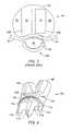
- Protective sleevestypically have distractors on a distal end. Distractors are projections that may be inserted into a disk space during a spinal fusion procedure. The distractors may serve to achieve and maintain distraction of adjacent vertebrae. Distractors may also help to secure the protective sleeve to the spinal column during the procedure. Protective sleeves may have one tube or two parallel tubes. FIG. 1 shows a single-tube protective sleeve, and FIG. 2 shows a dual-tube protective sleeve.
- FIG. 1illustrates a single-tube protective sleeve 30 used in a spinal fusion procedure.
- a spinal fusion procedureinvolves the insertion of one or more implants in a disk space between two vertebrae.
- Protective sleeve 30includes a substantially long, hollow tube 32 , two distractors 34 on opposite sides of an end of the tube, and two spikes 36 (only one shown) on opposite sides of the end of the tube.
- Protective sleeve 30is typically sufficiently long to allow access to a spinal column of a large patient during an anterior procedure.
- Protective sleeve 30may also be used in a posterior spinal fusion procedure.
- a spinal fusion procedure using implantstypically involves the insertion of two implants that are bilaterally positioned in an intervertebral disk space.
- the disk spaceis prepared by performing a discectomy and by distracting the vertebrae adjacent the disk space.
- a cap(not shown) is placed on end 38 of the protective sleeve 30 opposite distractors 34 to protect the end of the sleeve during insertion.
- Distractors 34may then be hammered into the disk space by striking the cap with a mallet (not shown).
- Spikes 36are hammered into disk bone on the vertebrae and help to stabilize protective sleeve 30 during the procedure.
- Distractors 34serve to separate the adjoining vertebrae to approximately normal spacing.
- a holeis drilled in the disk space by inserting a tool with a reaming head attachment through tube 32 and rotating the tool until a predetermined depth is reached. In some procedures, the hole is then tapped by inserting a tool with tap head attachment through tube 32 and rotating the tool until a predetermined depth is reached. The top and bottom of the reamed and tapped hole may extend into the end plates of the adjacent vertebrae.
- an implantmay be inserted in the hole by attaching the implant to an implant insertion tool and inserting the implant through tube 32 .
- the implantmay be hammered into the hole by striking the implant insertion tool with a mallet.
- the implantmay be threaded into the hole by turning the implant insertion tool. Then, the protective sleeve 30 may be removed.
- the protective sleeve 30is hammered in the disk space opposite the first implant and the procedure is repeated. Alternatively, the protective sleeve 30 may remain inserted in the disk space, and a second single-tube protective sleeve 30 may be inserted adjacent to the protective sleeve.
- the optimal alignment and spacing of implants in a spinal fusion proceduremay be determined before surgery. Achieving the predetermined alignment and spacing during surgery is often important for optimal fusing of the adjacent vertebrae.
- Protective sleeve 30has characteristics that may make achieving alignment difficult. First, each of the two holes is aligned, reamed, and tapped in a separate procedure. It is often difficult to align and space the holes correctly. Second, the alignment of protective sleeve 30 must be maintained after insertion. Any slight movement of protective sleeve 30 , which may act like a lever arm, may result in misalignment of the hole.
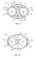
- FIG. 2illustrates a dual-tube protective sleeve 40 used in a spinal fusion procedure involving the insertion of two implants into a disk space.
- Protective sleeve 40includes substantially long, hollow tubes 32 , one or more distractors 34 and one or more spikes 36 .
- Protective sleeve 40is typically long enough to allow access during an anterior procedure to an intervertebral disk in a large patient.
- Spinal fusion using implants with protective sleeve 40involves the insertion of two implants, bilaterally positioned in parallel in an intervertebral disk space. During an anterior procedure, the disk space is prepared by performing a discectomy and by distracting the vertebrae adjacent the disk space.
- a cap(not shown) is placed on the end 42 of protective sleeve 40 opposite distractor 34 to protect the sleeve during insertion.
- Distractor 34is then hammered into the disk space by striking the cap with a mallet (not shown).
- Spikes 36are hammered into disk bone on the adjacent vertebrae to help stabilize protective sleeve 40 during the procedure.
- Distractor 34serves to separate the adjoining vertebrae to approximately normal spacing. After insertion, holes are reamed in the disk space by inserting a tool with a reaming head attachment through tubes 32 and rotating the tool until a predetermined depth is reached.
- the holesare tapped by inserting a tool with a tap head attachment through tubes 32 and rotating the tool until a predetermined depth is reached.
- the top and bottom of the reamed and tapped holesmay extend into the end caps of the adjacent vertebrae.
- implantsare inserted in the holes by attaching the implants to an implant insertion tool and inserting the implants through tubes 32 .
- the implantsare hammered into the hole by striking the implant insertion tool with a mallet.
- the implantsare threaded into the holes by turning the implant insertion tool. After both implants are inserted, protective sleeve 40 is removed.
- FIG. 3shows a representation of implants inserted into disk space 44 using a dual-tube protective sleeve 40 .
- Spinal nerves in the spinal canal 46are protected by dura 48 .
- Nerves 50extend from the spinal canal 46 .
- Implants 52are inserted between two vertebrae 54 (one shown). Care must be taken during insertion of the implants 52 to make sure that the implants do not impinge on the nerves 50 .
- dual-tube protective sleeve 40has characteristics that make it difficult to align the implants correctly.
- the alignment of protective sleeve 40must be maintained after insertion. Any slight movement of sleeve 40 , which may act like a lever arm, may result in misalignment of the hole.
- the long parallel tubesmake it difficult to angulate the two implants 52 relative to each other. Angulated implants may be the desired alignment in some spinal fusion procedures.
- Using a dual-tube protective sleeve 40has the advantage that the surgical procedure is simplified because there is only one insertion procedure, as opposed to two insertion procedures for a single-tube protective sleeve 30 .
- the sleevesare typically unitary members that are long enough to extend out of a ten-inch deep surgical opening after being hammered into place. To maintain alignment after insertion, the sleeve must be kept as motionless as possible. The sleeve tends to act like a lever arm, and any slight motion of the sleeve during the procedure may result in misalignment of the implants. The sleeve acting as a lever arm is particularly problematic when the sleeve is handed off during the surgical procedure from one member of the surgical team to another member of the surgical team.
- a second disadvantage of protective sleevesis related to the first disadvantage.
- the sleeveis held in place only by the distractors and the spikes inserted in the disk space.
- This connectionmay not be very secure. Because the connection is not secure, the sleeve may have to be held by the members of the surgical team throughout the entire procedure to maintain proper alignment. As noted above, any slight movement can result in the misalignment of the implants.
- a third disadvantage of protective sleevesis that they may afford minimal protection to surrounding tissues during a spinal fusion procedure.
- Major blood vesselsparallel the anterior surface of the spine for much of the spine's lower length. These vessels may be retracted during the procedure.
- the interface between the distal end of the sleeve and the spinal columnis typically not a perfect fit. Gaps may exist between the sleeve and the vertebrae. The presence of gaps creates the risk of drill bits, taps, and implants coming into contact with the blood vessels or other surrounding tissues during the procedure.
- the blood vesselsmay be pinched between the sleeve and the vertebrae. A nick or cut to either the aorta or the blood vessels can be life threatening.
- a holder or basethat allows for the insertion of instruments and spinal implants into a disk space during a spinal fusion procedure.
- distractors and tangs of a holdermay be driven into an intervertebral disc space. The distractors and tangs may secure the holder to the spine during.
- fasteners extending through a holder into the adjacent vertebraemay be used fix the holder to the spine.
- distractors, tangs, and fastenerssecure a holder to the spine.
- a flangemay be placed around the holder to protect the surrounding tissue and blood vessels. Protective sleeves may be inserted into and may be removed from conduits in the holder.
- a portion of the sleevemay have a slot or a window, located adjacent to the top of the holder.
- the slot or windowmay serve as a view-port to provide increased visibility near the procedure site.
- Surgical instrumentsmay be inserted through the protective sleeves and through the holder conduits to prepare the intervertebral space for an implant.
- An embodiment of a holderincludes a body, one or more conduits passing through the body from the top to the bottom, one or more distractors on the bottom of the body, and one or more tangs on the bottom of the body.
- the bodymay have a smooth outer surface with no sharp corners.
- the bodymay be flared near the bottom to provide shielding for surrounding tissue.
- the flared bottommay provide room for optional fasteners to extend at oblique angles from the body of the holder.
- the flared bodymay also provide the holder with a stable base against the spinal column.
- An optional flangemay be provided that fits around the outer surface of the holder.
- the flangemay provide shielding of soft tissue, such as blood vessels and organs, from cutting tools at the junction of the holder and the vertebral bodies.
- the flangemay also prevent damage to soft tissues due to pinching of the soft tissue between the holder and the vertebral bodies.
- the flangemay be made of a rigid or semi-rigid material.
- a portion of the flangemay be made of an elastic material so that the flange may stretch over and slide down the holder.
- the holdermay include a rim for holding the flange in place after installation.
- the holdermay include a groove for holding the flange in place.
- the flangehas an elastic collar, which holds the flange in place against the holder.
- the inner surfaces of the conduitsmay contain shoulders to limit the insertion distance of protective sleeves in the conduits.
- a conduitAbove a shoulder, a conduit may be sized to match the outer diameter of a protective sleeve. Below the shoulder, the conduit may be sized to match the outer diameter of instrument heads and implants to be used in the procedure.
- the shouldermay include slots configured to engage distractors on protective sleeves; thus allowing the holder to be used with single-tube protective sleeves having distractors.
- Embodiments of the holdermay have non-circular conduits.
- the cross sectional shape of the holder conduits and the protective sleeves inserted into the holdermay be any desired shape that allows for the insertion of spinal implants into a disk space.
- the cross sectional shape of the conduitsmay be rectangular if the cross sectional shape of the spinal implants are generally rectangular.
- Other embodiments of the holdermay have circular conduits or conduits which do not have a regular geometric shape.
- Embodiments of holders that have circular conduitsmay be constructed with conduits of different diameters to accommodate protective sleeves and implants of different diameters.
- Embodiments of holdersmay be provided with non-parallel angled conduits.
- Non parallel conduitsallow the insertion of implants at oblique angles to improve spinal fusion and to protect nerves posterior to the disk space.
- Other holder embodimentsmay have parallel conduits.
- the distractors on the bottom of the holder bodyare projections that insert into a disk space during a spinal fusion procedure.
- the distractorsmay serve to achieve and/or maintain distraction of the adjacent vertebrae.
- the distractorsmay also secure the holder to the spinal column during the procedure.
- the distractorsmay be substantially wedge-shaped, and may include curved surfaces.
- the tangs on the bottom of the holder bodymay serve to maintain distraction, and may also maintain a parallel orientation of the vertebrae during the procedure.
- the tangsmay also be substantially wedge-shaped, and may also include curved surfaces. Outer surfaces of the distractors and tangs may be serrated to secure the holder to adjacent vertebrae during a spinal fusion procedure.
- Curved inner surfaces on the tangs and curved surfaces on the distractormay serve as partially enclosed extensions of the conduits, and may help maintain alignment of the implant during a spinal fusion procedure.
- the bodyincludes one or more fastener holes for the insertion of fasteners into vertebrae.
- the fastener holesmay be angled so that fasteners inserted through the holes extend obliquely into adjacent vertebrae without damaging the vertebral endplates.
- the fastenersmay pass through the end caps of the vertebrae into cancellous bone in the interior of the vertebrae.
- the fastenersmay serve to substantially anchor the holder to the spine during the spinal fusion procedure.
- the height of the holder, when inserted in a spine,may be substantially less than the length of a protective sleeve.
- a protective sleevemay be inserted into a holder conduit when needed and removed when not needed without affecting alignment. Removal of a protective sleeve from the holder decreases the likelihood of a protective sleeve being inadvertently used as a lever arm during the procedure. Removing a protective sleeve from the holder may increase visibility at the procedure site. Removing a protective sleeve may also allow for easy irrigation of the entire surgical site, including the holes being prepared for the implants.
- FIG. 1illustrates a single-tube protective sleeve
- FIG. 2illustrates a dual-tube protective sleeve
- FIG. 3is a representation of implants inserted into a disk space with a dual-tube protective sleeve, or with an embodiment of a holder of the present invention that has parallel conduits;
- FIG. 4is a perspective view of a first embodiment of a holder
- FIG. 5is a front view the first embodiment holder
- FIG. 6is a side view the first embodiment holder
- FIG. 7is a cross-sectional view of the first embodiment holder taken substantially along line 7 - 7 of FIG. 6;
- FIG. 8is a cross-sectional view of the first embodiment holder taken substantially along line 8 - 8 of FIG. 5;
- FIG. 9is a top view of the first embodiment holder
- FIG. 10is a bottom view of the first embodiment holder
- FIG. 11is a top view of an embodiment of a holder flange
- FIG. 12is a top view of another embodiment of a holder flange
- FIG. 13is a perspective view of an embodiment of a holder flange with a collar
- FIG. 14is a perspective view of an embodiment of a holder flange
- FIG. 15is a perspective view of an embodiment of a holder without conduit extenders
- FIG. 16is a cross sectional view of an embodiment of a holder having a flange groove
- FIG. 17is a cross sectional view of an embodiment of a holder without body flare
- FIG. 18is a cross sectional view of an embodiment of a holder with an alternative fastener hole arrangement
- FIG. 19is a perspective view of an embodiment of a holder having serrated distractors and tangs
- FIG. 20is a perspective view of an embodiment of a holder having an extended upper opening and an insertion tool slot.
- FIG. 21is a perspective view of the embodiment shown in FIG. 20;
- FIG. 22is a perspective view of an insertion tool for an embodiment of a holder
- FIG. 23is a perspective view of an alternate embodiment holder having overlapping conduits
- FIG. 24is a top view of a possible arrangement of implants inserted into a disk space using the holder of FIG. 23;
- FIG. 25is a perspective view of a holder having one conduit
- FIG. 26is a perspective view of a holder with an inserted protective sleeve and tool
- FIG. 27is a front view of a holder with an alternate protective sleeve
- FIGS. 28 a - 28 eillustrate steps included in a spinal fusion procedure using an embodiment of a holder
- FIG. 29illustrates the positioning of major blood vessels around one embodiment of a holder during a typical L 5 /S 1 fusion procedure
- FIG. 30illustrates the positioning of major blood vessels around one embodiment of a holder during a typical L 4 /L 5 fusion procedure
- FIG. 31illustrates the angulation of implants inserted using one embodiment of a holder.
- a holder or base for use as an insertion guide during a spinal implantation procedureis designated generally as 100 .
- a holdermay be used to support a sleeve during a spinal fusion procedure, and a base may be used with or without a sleeve during a spinal fusion procedure.
- a holdermay be used as a base, and a base may be used as a holder.
- FIGS. 4 - 10show views of a first embodiment of the holder 100 .
- the holder 100may include unitary body 102 , conduits 104 through the body, conduit extenders 106 , flared portion 108 , flange rim 110 , holes 112 , distractor 114 , and tangs 116 .
- the height of the holder bodymay be less than about six inches. Preferably, the holder height is less than four inches, and more preferably, less than 2 inches.
- the conduits 104may have circular cross sections. Alternatively, the conduits 104 may have any desired cross sectional shape, such as rectangular or ellipsoid, to correspond to instruments and implants used during a spinal fusion procedure.
- the body 102may have flared portion 108 .
- the flared portion 108may allow for angulation of fastener holes 112 , as shown in FIG. 8.
- Fastener holes 112may be located in slot 118 .
- Angulated fastener holes 112allow fasteners 120 inserted through the fastener holes to penetrate adjacent vertebrae 54 through end caps 122 of the vertebrae and into cancellous bone 124 , as shown in FIG. 28 c. Attaching the holder 100 to the vertebrae 54 with fasteners 120 placed through end caps 122 may minimize weakening of the end plates 126 of the vertebrae. Shoulders 128 limit the insertion depth of the fasteners 120 into the holder 100 .
- Fasteners 120may be any type of fastening device including, but not limited to, screws, nails, rivets, trocars, pins, and barbs.
- the flared portion 108 of the body 102may shield blood vessels, nerves, and other soft tissue from damage by the body and tools used during the spinal fusion procedure.
- the flared portion 108increases the circumference of holder 100 to a maximum near flange rim 110 .
- Optional flange 130may slip over the top of holder 100 and reside against the rim 110 .
- the flared portion 108may also provide a stable base on the end caps 122 of the vertebrae 54 for holder 100 .
- the perimeter of the conduit 104 at a top end of the holder 100may match the outer perimeter of protective sleeve 132 inserted into the conduit.
- the conduits 104may include shoulders 134 .
- a shoulder 134prevents insertion of a protective sleeve 132 into a conduit 104 beyond a certain depth.
- a conduit 104may include slots 136 .
- the slots 136correspond to the shape of the distractors 34 on the ends of single-tube protective sleeves 30 . Slots 136 allow a holder 100 to be used with a single-tube protective sleeve 30 having distractors 34 , such as the sleeve shown in FIG. 1.
- conduits 104may be configured to receive protective sleeves 132 without distractors 34 by having shoulders 128 which extend fully around the diameter of the conduits 104 .
- a protective sleeve 132may be slid into a conduit 104 without the use of an insertion tool.
- FIG. 7shows a cross sectional view of the first embodiment holder 100 with the conduits 104 angulated toward one another. Having the conduits angled relative to one another allows for the angulation of implants 52 .
- Angulated implants 52may provide a more stable fusion of vertebrae 54 .
- angulated implants 52may be less likely to protrude from posterior side 138 of the disk space to press on nerves 50 exiting the spinal canal 46 .
- the angle Alocated between a center line of a first conduit 104 and a centerline of an adjacent conduit, may vary from 0 to about 30 degrees, preferably the angle A is less than about 20 degrees, and more preferably, the angle A is less than about 10 degrees. If the angle A is 0 degrees, then the adjacent conduits 104 are parallel.
- Flange rim 110may support flange 130 .
- the flange 130may serve to protect blood vessels and other tissue placed upon the flange 130 and near the body 102 of the holder 100 .
- FIGS. 11 - 14show some flange embodiments.
- ends 140 of the flange 130are relatively wide to provide extra protection and a support area on the sides of the holder 100 where the blood vessels are most likely to be placed.
- the flange 130may have flexible collar 142 to more securely attach the flange to the body 102 of a holder 100 .
- the shape of the flange 130 during usemay correspond to the anterior surface of the spine so that a snug fit against the spine is established during a spinal fusion procedure.
- the snug fitmay help prevent tools used during the procedure from contacting and potentially damaging adjacent tissue.
- the flange 130may be made of a semi-rigid elastic or plastic material so that an inner edge of the flange conforms to the shape of the holder body 102 after the flange has been stretched over and slid down the body. As shown in FIG. 14, the flange may have narrow brims 144 , and relatively short ends 140 . The ends 140 of the flange 130 are long enough to be easily positionable under adjacent vessels and tissue.
- the distractors 114 and tangs 116are protrusions, which may extend from the bottom of the holder body 102 .
- Distractor 114may serve to maintain distraction of adjacent vertebrae 54 during a spinal fusion procedure.
- the distractor 114may establish a separation distance between the vertebrae during the procedure.
- Tangs 116may also serve to maintain distraction.
- the tangsmay maintain a parallel orientation of the vertebrae 54 during the procedure.
- Distractor 114 and tangs 116may be substantially wedge-shaped to facilitate insertion into the disk space 44 .
- Surfaces of distractor 114 and tangs 116may be curved to match the curvature of the conduits 104 , so that the distractor and tangs serve as partially enclosed extensions of conduits.
- Bottom 146 of the holder 100may conform to the general shape of a vertebra 54 .
- portions of the bottom 146 of the holder 100may reside on end caps 122 of adjacent vertebrae 54 .
- Having the bottom 146 of the holder 100 shaped to conform to the shape of the vertebrae 54may help to protect adjacent soft tissue and vessels from being pinched between the holder and the vertebrae during the spinal fusion procedure.
- FIGS. 15 - 21show some alternate embodiments of a holder 100 .
- FIG. 15shows a holder without conduit extenders on the body 102 .
- FIG. 16shows a cross sectional view of a holder 100 with flange groove 148 .
- the flange groove 148may support an inner edge of a flange 130 to hold the flange at a desired position on the body 102 .
- FIGS. 16 and 17show cross sectional views of holders 100 without fastener holes.
- FIG. 17also shows the holder without a flared portion and without a flange rim or a flange groove.
- FIG. 18shows a cross sectional view of another embodiment holder with an alternate fastener hole 112 arrangement.
- fastener holes 112extend between conduits 104 from the top of body 102 downwards at an oblique angle relative to a vertical axis of holder 100 .
- the fastener holes 112cross at point 150 and then exit near an outer edge of the lower portion of body 102 .
- the fastener holes 112include shoulders 128 to limit the insertion depth of fasteners 120 into fastener holes 112 .
- one fastener 120is inserted into a fastener hole 112 and into a vertebra 54 until the head of the fastener is past the cross point 150 .
- fastener 120is inserted into the remaining fastener hole 112 and the fastener is inserted into the adjacent vertebra 54 . Both fasteners 120 may be further inserted into the vertebrae 54 until the fastener heads contact the shoulders 128 .
- FIG. 19shows an embodiment of a holder 100 , which has serrations 154 on outer edges of the distractor 114 and on the outer edges of the tangs 116 .
- Serrations 154may maintain proper alignment and the serrations may inhibit the distractor 114 and tangs 116 from backing out of the vertebrae 54 after the holder 100 is inserted during a spinal fusion procedure.
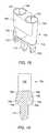
- FIG. 20 and FIG. 21show perspective views of an alternate embodiment of a holder 100 .
- the body 102may include flat sections 156 , large top opening 158 , undercut tool slots 160 , spring stop 162 , and ball 164 .
- the flat sections 156may help to make the holder 100 easier to machine during the manufacturing.
- the holdermay have large top opening 158 with conduits 104 located in a lower section of the body.
- the body 102may have undercut tool slots 160 (only one shown).
- Coil springs(not shown) are placed in the body 102 between the spring stops 162 and the balls 164 (only one shown).
- the spring stops 162 , coil springs and balls 164form an assembly that removably connects an insertion tool 166 to the holder 100 .
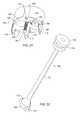
- FIG. 22shows a perspective view of the insertion tool 166 used with the holder shown in FIG. 20 and FIG. 21.
- the insertion tool 166includes attachment head 168 , dimples 170 , shaft 172 , and top member 174 .
- the attachment head 168 of the insertion tool 166is inserted into the top opening 158 of the body 102 .
- the insertion tool 166is rotated approximately 90 degrees. Rotating the insertion tool 166 forces the balls 164 in the holder body 102 against the coil springs, and compresses the springs. When the dimples 170 align with balls 164 , the springs force the balls into the dimples and attach the insertion tool 166 to the holder 100 .
- the insertion toolWhen the holder 100 is attached to the insertion tool 166 , the insertion tool functions as a handle and allows the holder to be positioned at a desired location.
- a mallet(not shown) may be used to strike upper surface 176 of the top member 174 to insert the holder into a disk space 44 after the holder is positioned at a desired location.
- the insertion toolis rotated approximately 90 degrees, and the attachment head 168 is removed from the opening 158 .
- FIG. 23shows a perspective view of an embodiment of a holder 100 wherein the conduits 104 of the holder overlap.
- the holderhas a pair of distractors 114 located at opposite sides of the body 102 .
- FIG. 24shows a schematic representation of one possible arrangement of implants 52 , 53 inserted in a disk space 44 with the, embodiment of a holder 100 shown in FIG. 23.
- FIG. 25shows an embodiment of the holder 100 having one conduit 104 extending through the body 102 .
- the holder 100may have a pair of distractors 114 located at opposite sides of the conduit 104 .
- the holdermay have fastener holes (not shown) that allow fasteners to attach the holder to vertebrae 54 during a spinal fusion procedure.
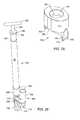
- FIG. 26illustrates an embodiment of a holder 100 with protective sleeve 132 , driver 180 , and attachment 182 .
- Tube 32 of protective sleeve 132may be inserted in one of the conduits 104 of holder 100 .
- Shaft 184 of driver 180may be inserted in tube 32 .
- At least a portion of shaft 184may have a diameter substantially equal to the inside diameter of tube 32 to maintain alignment of the driver 180 during use.
- Stop 186may serve to limit the distance shaft 184 may be inserted into tube 32 .
- stop 186may be adjustable to allow different insertion depths.
- the driver 180may have handle 188 for turning shaft 184 located on an end of the shaft.
- Attachment 182may be located on an end of the shaft opposite to the handle 188 . Attachments may include, but are not limited to, drilling heads and tapping heads. An implant 52 may also be coupled to the distal end of a driver for insertion into a disc space 44 .
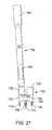
- FIG. 27illustrates an embodiment of a protective sleeve 132 prior to insertion into an embodiment of a holder 100 .
- the protective sleeve 132includes widened portion 190 at an end of the sleeve.
- the widened portion 190receives a tool (not shown) having a complementary wide portion at an end of the tool.
- the sleeve 132may include view-port 192 to provide improved visibility of the surgical site during the procedure.
- the view-portmay be a window, a slot, or other structure that allows increased allows increased visibility of the surgical site during the procedure.
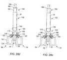
- FIGS. 28 a - 28 eillustrate steps included in a spinal fusion procedure using an embodiment of a holder 100 .
- holder 100is shown being inserted into disk space 44 between adjacent vertebrae 54 .
- Distractor 114may be driven into the disk space 44 by striking insertion device 194 with mallet 196 .
- Insertion device 194may fit in the conduits 104 .
- insertion device 194may fit between conduits 104 in slot 118 to provide a contact surface with the holder 100 for hammering.
- the insertion devicemay be an insertion tool 166 as shown in FIG. 22.
- the insertion device 194may be coupled with holder 100 prior to insertion into the surgical cavity, and may be used as a handle for inserting and positioning holder 100 by the surgeon prior to and during hammering.
- Distractor 114separates vertebrae 54 as the distractor is hammered in. The distractor widens the disk space 44 to the desired width for the procedure.
- Holder 100may be hammered with the mallet 196 until the bottom 146 of body 102 makes substantial contact with the adjacent vertebra 54 .
- holder 100has been hammered into the disk space 44 to an optimal depth.
- Optional flange 130may then be slipped over the top of holder 100 to fit snugly against flange rim 110 .
- blood vessels 198such as the aorta and vena cava, which are retracted to one side during the installation of the holder 100 , may be placed over flange 130 next to body 102 , as shown in FIG. 29 and FIG. 30.
- the shape of flange 130serves to protect the blood vessels 198 from being pinched, nicked or cut during the remainder of the spinal fusion procedure.
- Body 102may be formed with smooth, arcuate outer surfaces with no sharp comers to further protect blood vessels 198 and tissue.
- FIG. 28 cshows the insertion of optional fasteners 120 in fastener holes 112 , through end caps 122 and into cancellous bone 124 of vertebrae 54 .
- Angling of fasteners 120 into cancellous bone 124avoids vertical penetration deep into the end plates 126 ; thus helping to prevent weakening of the endplates near the implants 52 .
- the head of driver 200may fit into slot 118 to contact a fastener 120 .
- the slot 118may protect surrounding soft tissues should the head of the driver 200 slip off the fastener 120 .
- Slot 118may also help contain a fastener 120 should the fastener be dropped during the insertion process.
- the heads of fasteners 120may include hex or star shaped slots for receiving a corresponding driver 200 .
- driver 200may include a bent or bendable shaft to facilitate the angled insertion of the fasteners 120 in the fastener holes 112 .
- the shaft of driver 200may be long enough to allow the surgeon to turn the driver above the surgical cavity while the head of the driver is coupled to the head of a fastener 120 .
- a fastener 120may be coupled to the driving head of driver 200 to help prevent dropping the fastener into the surgical cavity during insertion.
- protective sleeve 132is inserted in one of the conduits 104 of the holder 100 .
- Shaft 184 of driver 180is inserted into the protective sleeve 132 .
- Stop 186serves to limit the distance shaft 184 may be inserted into sleeve 132 .
- Drilling head 182may be coupled to the distal end of driver 180 .
- a handle (not shown) coupled to the proximal end of driving shaft 184may be turned while applying downward pressure on driver 180 to drill out a hole in disk space 44 . Drilling the hole may also remove bone from the end plates 126 of adjacent vertebrae 54 .
- Flange 130may protect adjacent blood vessels 198 and other soft tissues during the drilling process.
- driver 180is retracted and a tap (not shown) is attached to the driver.
- the tap and the driver 180are inserted into the sleeve 132 .
- a handle (not shown) coupled to an end of the driving shaft 184is turned while applying downward pressure on driver 180 to tap a flight of threads in the vertebrae 54 .
- the driveris removed from the protective sleeve 132 .
- a threaded implant 52is coupled to the distal end of an implant insertion tool 202 .
- the implant insertion tool 202is inserted into the sleeve 132 .
- a handle (not shown) coupled to the proximal end of implant insertion tool 132is turned while applying downward pressure to screw implant 52 into the threaded hole in disk space 44 .
- an unthreaded implant 52is coupled to an end of an implant insertion tool 202 .
- the implant insertion tool 202is inserted into the protective sleeve 132 .
- a mallet(not shown) is used to strike the proximal end of implant insertion tool 202 to drive implant 52 into the disk space 44 .
- inserted implant 52is then detached from insertion tool 202 .
- Protective sleeve 132may then be removed from the conduit 104 of holder 100 and inserted into the adjacent holder conduit 104 .
- a second protective sleeve 132may be inserted in the adjacent conduit 104 .
- the steps described for FIGS. 28 d - 28 emay then be repeated for the installation of the second implant.
- fasteners 120may be backed out of vertebrae 54 and holder 100 may be removed from the disk space 44 .
- FIGS. 28 a - 28 eAn advantage of holder 100 illustrated in FIGS. 28 a - 28 e is that the tools and protective sleeve 132 may be removed at any time during the procedure without affecting the alignment or spacing of the holder 100 . Fixing the holder 100 to the vertebrae with fasteners 120 , and inserting the protective sleeve 132 into the holder 100 only when necessary may minimize the risk of misalignment of implants 52 during a spinal fusion procedure.
- FIG. 29illustrates the positioning of major blood vessels 198 around a dual-conduit holder 100 during an L 5 /S 1 fusion procedure.
- Holder 100is shown inserted in disk space 44 (L 5 /S 1 ) between vertebra 54 (L 5 ) and sacrum 204 (S 1 ).
- the bifurcation of major blood vessels 198typically is proximate vertebra L 5 .
- the right branch and left branch of major blood vessels 198are shown separated and placed over holder flange 130 .
- the bifurcation point of the major blood vessels 198may be located higher or lower than proximate the L 5 vertebra.
- An irregularly located bifurcation point of the major blood vessels 198may require the branches of the major blood vessels to be routed around one side of holder 100 .
- FIG. 30illustrates the positioning of major blood vessels 198 around a holder 100 during an L 4 /L 5 fusion process.
- Holder 100is shown inserted in disk space 44 (L 4 /L 5 ) between adjacent vertebrae 54 (L 4 and L 5 ).
- the bifurcation of major blood vessels 198typically is proximate vertebra L 5 .
- the major blood vessels 198are shown placed over holder 100 upon flange 130 .
- the blood vesselsmay be placed on either side of holder 100 .
- the configuration of holder 100 and the added protection of flexible flange 130may serve to protect the blood vessels 198 from being nicked during the spinal fusion procedure.
- the body 102 of holder 100may be curved and may lack sharp comers or edges to further protect the blood vessels 198 and other tissue from abrasion.
- Protecting the blood vessels 198is critical in a spinal fusion procedure, as the aorta is a major artery and the vena cava is a major vein. Even a tiny nick in either blood vessel 198 is potentially catastrophic, and must be repaired quickly.
- a nick in the vena cavais particularly problematic because the vena cava has thinner walls than the aorta, making the vena cava easier to nick and harder to repair than the aorta.
- FIG. 3illustrates the orientation of implants 52 inserted using dual-tube protective sleeves 40 or an embodiment of holder 100 that has an angle A value of 0 degrees.
- Implants 52are shown inserted in parallel in disk space 44 .
- Spinal nerves within the spinal canal 46 and protective sheath 48(also called the dura) are shown posterior to disk space 44 .
- Nerves 50exit the sides of spinal canal 46 .
- An end 206 of an implant 52may put pressure on nerves 50 if the implant is inserted far enough to allow ends to protrude out the posterior side 138 of disk space 44 . Pressure on the nerves may lead to severe post-operative pain or nerve damage for the patient.
- FIG. 31illustrates the angulation of implants inserted using one embodiment of a holder 100 .
- Implants 52are shown inserted angled inwards in disk space 44 .
- Nerves 50are shown exiting from the sides of spinal canal 46 . If implants 52 are inserted far enough that ends 206 protrude out the posterior side 138 of the disk space 44 , ends 206 may be more likely to put pressure on dura 48 than on nerves 50 .
- Dura 48may be less likely to be negatively affected by the pressure than nerves 50 .
- FIG. 31Also shown in FIG. 31 is an embodiment of a holder 100 inserted in disk space 44 .
- the curvature of bottom 146 of holder 100may substantially match the curvature of the anterior surface of the adjacent vertebrae 54 .
- the close fit between the vertebrae 54 and the holder 100may help protect blood vessels 198 and other soft tissues from being pinched between the vertebrae and the holder during the spinal fusion procedure.
- the angulation of conduits 104is shown as angle A.
- Different embodiments of holder 100may be made with a wide range of angles A to be used in spinal fusion procedures requiring different optimal angulations of implants 52 . Most procedures may fall between 0 degrees and 30 degrees. Approximately 8 degrees may be the optimal angulation for implants 52 in many procedures.
Landscapes
- Health & Medical Sciences (AREA)
- Orthopedic Medicine & Surgery (AREA)
- Engineering & Computer Science (AREA)
- Biomedical Technology (AREA)
- Life Sciences & Earth Sciences (AREA)
- Transplantation (AREA)
- General Health & Medical Sciences (AREA)
- Veterinary Medicine (AREA)
- Oral & Maxillofacial Surgery (AREA)
- Heart & Thoracic Surgery (AREA)
- Public Health (AREA)
- Surgery (AREA)
- Animal Behavior & Ethology (AREA)
- Physical Education & Sports Medicine (AREA)
- Vascular Medicine (AREA)
- Cardiology (AREA)
- Dentistry (AREA)
- Nuclear Medicine, Radiotherapy & Molecular Imaging (AREA)
- Neurology (AREA)
- Medical Informatics (AREA)
- Molecular Biology (AREA)
- Prostheses (AREA)
- Surgical Instruments (AREA)
Abstract
Description
- 1. Field of the Invention[0001]
- The present invention generally relates to spinal fixation and fusion systems. The invention also generally relates to an insertion guide used during the insertion of a spinal implant system, wherein the implant system is used for correction, fixation, and/or stabilization of the spine.[0002]
- 2. Description of the Related Art[0003]
- Intervertebral disks that become degenerated due to various factors such as trauma or aging typically have to be partially or fully removed. Removal of an intervertebral disk can destabilize the spine, making it necessary to replace the vertebral disk to maintain the height of the spine and to fuse the spine. Spinal implants are often used to prevent collapse of the spine. In a typical spinal fusion procedure, an intervertebral disk is removed and implants are inserted in the disk space between neighboring vertebrae. The implants maintain normal disk spacing and help restore spinal stability.[0004]
- The implants may be constructed of any biocompatible materials sufficiently strong to maintain spinal distraction including, but not limited to, bone, stainless steel, or inert metals. Implants are typically packed with bone graft or a synthetic bone graft substitute to facilitate spinal fusion. Implants may have a variety of shapes, which include, but are not limited to, threaded cylinders, unthreaded cylinders, and parallelepipeds.[0005]
- An anterior spinal fusion procedure is often preferred to a posterior spinal fusion procedure. An anterior spinal fusion procedure may require less bone removal and muscle distraction than a posterior spinal fusion procedure. Also, an anterior spinal fusion procedure may involve less risk of nerve damage than a posterior spinal fusion procedure. In an anterior spinal fusion procedure, a surgical opening in the abdomen may be up to ten inches deep. A protective sleeve may be used during preparation and insertion of a spinal implant. The protective sleeve may serve to protect abdominal organs, blood vessels and other tissue during the spinal implant procedure. The sleeve typically extends above the surgical opening during use. The sleeve may maintain distraction of the vertebrae. Also, the sleeve may serve as an alignment guide for tool and implant insertion during the surgical procedure.[0006]
- Protective sleeves typically have distractors on a distal end. Distractors are projections that may be inserted into a disk space during a spinal fusion procedure. The distractors may serve to achieve and maintain distraction of adjacent vertebrae. Distractors may also help to secure the protective sleeve to the spinal column during the procedure. Protective sleeves may have one tube or two parallel tubes. FIG. 1 shows a single-tube protective sleeve, and FIG. 2 shows a dual-tube protective sleeve.[0007]
- FIG. 1 illustrates a single-tube[0008]
protective sleeve 30 used in a spinal fusion procedure. A spinal fusion procedure involves the insertion of one or more implants in a disk space between two vertebrae.Protective sleeve 30 includes a substantially long,hollow tube 32, twodistractors 34 on opposite sides of an end of the tube, and two spikes36 (only one shown) on opposite sides of the end of the tube.Protective sleeve 30 is typically sufficiently long to allow access to a spinal column of a large patient during an anterior procedure.Protective sleeve 30 may also be used in a posterior spinal fusion procedure. - A spinal fusion procedure using implants typically involves the insertion of two implants that are bilaterally positioned in an intervertebral disk space. During an anterior procedure, the disk space is prepared by performing a discectomy and by distracting the vertebrae adjacent the disk space. A cap (not shown) is placed on[0009]
end 38 of theprotective sleeve 30opposite distractors 34 to protect the end of the sleeve during insertion.Distractors 34 may then be hammered into the disk space by striking the cap with a mallet (not shown).Spikes 36 are hammered into disk bone on the vertebrae and help to stabilizeprotective sleeve 30 during the procedure.Distractors 34 serve to separate the adjoining vertebrae to approximately normal spacing. - After insertion, a hole is drilled in the disk space by inserting a tool with a reaming head attachment through[0010]
tube 32 and rotating the tool until a predetermined depth is reached. In some procedures, the hole is then tapped by inserting a tool with tap head attachment throughtube 32 and rotating the tool until a predetermined depth is reached. The top and bottom of the reamed and tapped hole may extend into the end plates of the adjacent vertebrae. After the hole is prepared, an implant may be inserted in the hole by attaching the implant to an implant insertion tool and inserting the implant throughtube 32. For untapped holes, the implant may be hammered into the hole by striking the implant insertion tool with a mallet. For tapped holes, the implant may be threaded into the hole by turning the implant insertion tool. Then, theprotective sleeve 30 may be removed. - If a second implant is to be inserted, the[0011]
protective sleeve 30 is hammered in the disk space opposite the first implant and the procedure is repeated. Alternatively, theprotective sleeve 30 may remain inserted in the disk space, and a second single-tubeprotective sleeve 30 may be inserted adjacent to the protective sleeve. - The optimal alignment and spacing of implants in a spinal fusion procedure may be determined before surgery. Achieving the predetermined alignment and spacing during surgery is often important for optimal fusing of the adjacent vertebrae.[0012]
Protective sleeve 30 has characteristics that may make achieving alignment difficult. First, each of the two holes is aligned, reamed, and tapped in a separate procedure. It is often difficult to align and space the holes correctly. Second, the alignment ofprotective sleeve 30 must be maintained after insertion. Any slight movement ofprotective sleeve 30, which may act like a lever arm, may result in misalignment of the hole. - FIG. 2 illustrates a dual-tube[0013]
protective sleeve 40 used in a spinal fusion procedure involving the insertion of two implants into a disk space.Protective sleeve 40 includes substantially long,hollow tubes 32, one ormore distractors 34 and one ormore spikes 36.Protective sleeve 40 is typically long enough to allow access during an anterior procedure to an intervertebral disk in a large patient. Spinal fusion using implants withprotective sleeve 40 involves the insertion of two implants, bilaterally positioned in parallel in an intervertebral disk space. During an anterior procedure, the disk space is prepared by performing a discectomy and by distracting the vertebrae adjacent the disk space. A cap (not shown) is placed on theend 42 ofprotective sleeve 40opposite distractor 34 to protect the sleeve during insertion.Distractor 34 is then hammered into the disk space by striking the cap with a mallet (not shown).Spikes 36 are hammered into disk bone on the adjacent vertebrae to help stabilizeprotective sleeve 40 during the procedure.Distractor 34 serves to separate the adjoining vertebrae to approximately normal spacing. After insertion, holes are reamed in the disk space by inserting a tool with a reaming head attachment throughtubes 32 and rotating the tool until a predetermined depth is reached. In some procedures, the holes are tapped by inserting a tool with a tap head attachment throughtubes 32 and rotating the tool until a predetermined depth is reached. The top and bottom of the reamed and tapped holes may extend into the end caps of the adjacent vertebrae. After the holes are prepared, implants are inserted in the holes by attaching the implants to an implant insertion tool and inserting the implants throughtubes 32. For untapped holes, the implants are hammered into the hole by striking the implant insertion tool with a mallet. For tapped holes, the implants are threaded into the holes by turning the implant insertion tool. After both implants are inserted,protective sleeve 40 is removed. - FIG. 3 shows a representation of implants inserted into[0014]
disk space 44 using a dual-tubeprotective sleeve 40. Spinal nerves in thespinal canal 46 are protected bydura 48.Nerves 50 extend from thespinal canal 46.Implants 52 are inserted between two vertebrae54 (one shown). Care must be taken during insertion of theimplants 52 to make sure that the implants do not impinge on thenerves 50. - Like single-tube[0015]
protective sleeve 30, dual-tubeprotective sleeve 40 has characteristics that make it difficult to align the implants correctly. First, the alignment ofprotective sleeve 40 must be maintained after insertion. Any slight movement ofsleeve 40, which may act like a lever arm, may result in misalignment of the hole. Second, the long parallel tubes make it difficult to angulate the twoimplants 52 relative to each other. Angulated implants may be the desired alignment in some spinal fusion procedures. Using a dual-tubeprotective sleeve 40 has the advantage that the surgical procedure is simplified because there is only one insertion procedure, as opposed to two insertion procedures for a single-tubeprotective sleeve 30. - Single- and dual-tube protective sleeves share some disadvantages. First, the sleeves are typically unitary members that are long enough to extend out of a ten-inch deep surgical opening after being hammered into place. To maintain alignment after insertion, the sleeve must be kept as motionless as possible. The sleeve tends to act like a lever arm, and any slight motion of the sleeve during the procedure may result in misalignment of the implants. The sleeve acting as a lever arm is particularly problematic when the sleeve is handed off during the surgical procedure from one member of the surgical team to another member of the surgical team.[0016]
- A second disadvantage of protective sleeves is related to the first disadvantage. The sleeve is held in place only by the distractors and the spikes inserted in the disk space. This connection may not be very secure. Because the connection is not secure, the sleeve may have to be held by the members of the surgical team throughout the entire procedure to maintain proper alignment. As noted above, any slight movement can result in the misalignment of the implants.[0017]
- A third disadvantage of protective sleeves is that they may afford minimal protection to surrounding tissues during a spinal fusion procedure. Major blood vessels, parallel the anterior surface of the spine for much of the spine's lower length. These vessels may be retracted during the procedure. The interface between the distal end of the sleeve and the spinal column is typically not a perfect fit. Gaps may exist between the sleeve and the vertebrae. The presence of gaps creates the risk of drill bits, taps, and implants coming into contact with the blood vessels or other surrounding tissues during the procedure. Also, the blood vessels may be pinched between the sleeve and the vertebrae. A nick or cut to either the aorta or the blood vessels can be life threatening.[0018]
- The above-mentioned methods and systems inadequately address the need to angulate implants in some spinal fusion procedures, the need to maintain precise alignment throughout the procedure, and the need to protect surrounding tissues during the procedure. It is therefore desirable that an improved method and system be derived for inserting spinal implants during a spinal fusion procedure.[0019]
- The problems outlined above may in large part be solved by a holder or base that allows for the insertion of instruments and spinal implants into a disk space during a spinal fusion procedure. In an embodiment, distractors and tangs of a holder may be driven into an intervertebral disc space. The distractors and tangs may secure the holder to the spine during. In an embodiment, fasteners extending through a holder into the adjacent vertebrae may be used fix the holder to the spine. In another embodiment, distractors, tangs, and fasteners secure a holder to the spine. A flange may be placed around the holder to protect the surrounding tissue and blood vessels. Protective sleeves may be inserted into and may be removed from conduits in the holder. A portion of the sleeve may have a slot or a window, located adjacent to the top of the holder. The slot or window may serve as a view-port to provide increased visibility near the procedure site. Surgical instruments may be inserted through the protective sleeves and through the holder conduits to prepare the intervertebral space for an implant.[0020]
- An embodiment of a holder includes a body, one or more conduits passing through the body from the top to the bottom, one or more distractors on the bottom of the body, and one or more tangs on the bottom of the body. The body may have a smooth outer surface with no sharp corners. In some embodiments, the body may be flared near the bottom to provide shielding for surrounding tissue. The flared bottom may provide room for optional fasteners to extend at oblique angles from the body of the holder. The flared body may also provide the holder with a stable base against the spinal column.[0021]
- An optional flange may be provided that fits around the outer surface of the holder. The flange may provide shielding of soft tissue, such as blood vessels and organs, from cutting tools at the junction of the holder and the vertebral bodies. The flange may also prevent damage to soft tissues due to pinching of the soft tissue between the holder and the vertebral bodies. The flange may be made of a rigid or semi-rigid material. A portion of the flange may be made of an elastic material so that the flange may stretch over and slide down the holder. In one embodiment, the holder may include a rim for holding the flange in place after installation. In another embodiment, the holder may include a groove for holding the flange in place. In another embodiment, the flange has an elastic collar, which holds the flange in place against the holder.[0022]
- In some embodiments, the inner surfaces of the conduits may contain shoulders to limit the insertion distance of protective sleeves in the conduits. Above a shoulder, a conduit may be sized to match the outer diameter of a protective sleeve. Below the shoulder, the conduit may be sized to match the outer diameter of instrument heads and implants to be used in the procedure. In some embodiments, the shoulder may include slots configured to engage distractors on protective sleeves; thus allowing the holder to be used with single-tube protective sleeves having distractors.[0023]
- Embodiments of the holder may have non-circular conduits. The cross sectional shape of the holder conduits and the protective sleeves inserted into the holder may be any desired shape that allows for the insertion of spinal implants into a disk space. For example, the cross sectional shape of the conduits may be rectangular if the cross sectional shape of the spinal implants are generally rectangular. Other embodiments of the holder may have circular conduits or conduits which do not have a regular geometric shape. Embodiments of holders that have circular conduits may be constructed with conduits of different diameters to accommodate protective sleeves and implants of different diameters.[0024]
- Embodiments of holders may be provided with non-parallel angled conduits. Non parallel conduits allow the insertion of implants at oblique angles to improve spinal fusion and to protect nerves posterior to the disk space. Other holder embodiments may have parallel conduits.[0025]
- The distractors on the bottom of the holder body are projections that insert into a disk space during a spinal fusion procedure. The distractors may serve to achieve and/or maintain distraction of the adjacent vertebrae. The distractors may also secure the holder to the spinal column during the procedure. The distractors may be substantially wedge-shaped, and may include curved surfaces. The tangs on the bottom of the holder body may serve to maintain distraction, and may also maintain a parallel orientation of the vertebrae during the procedure. The tangs may also be substantially wedge-shaped, and may also include curved surfaces. Outer surfaces of the distractors and tangs may be serrated to secure the holder to adjacent vertebrae during a spinal fusion procedure.[0026]
- In one embodiment, there is one distractor centrally located between two conduits; and two tangs, with one next to each conduit opposite the distractor. Curved inner surfaces on the tangs and curved surfaces on the distractor may serve as partially enclosed extensions of the conduits, and may help maintain alignment of the implant during a spinal fusion procedure.[0027]
- In some embodiments, the body includes one or more fastener holes for the insertion of fasteners into vertebrae. The fastener holes may be angled so that fasteners inserted through the holes extend obliquely into adjacent vertebrae without damaging the vertebral endplates. The fasteners may pass through the end caps of the vertebrae into cancellous bone in the interior of the vertebrae. The fasteners may serve to substantially anchor the holder to the spine during the spinal fusion procedure.[0028]
- The height of the holder, when inserted in a spine, may be substantially less than the length of a protective sleeve. During the spinal fusion procedure, a protective sleeve may be inserted into a holder conduit when needed and removed when not needed without affecting alignment. Removal of a protective sleeve from the holder decreases the likelihood of a protective sleeve being inadvertently used as a lever arm during the procedure. Removing a protective sleeve from the holder may increase visibility at the procedure site. Removing a protective sleeve may also allow for easy irrigation of the entire surgical site, including the holes being prepared for the implants.[0029]
- The ability to remove the protective sleeves when not in use, the short profile of the holder, and the fastener anchoring system all help to maintain proper alignment during the insertion of implants in a spinal fusion procedure.[0030]
- Further advantages of the present invention will become apparent to those skilled in the art with the benefit of the following detailed description of embodiments and upon reference to the accompanying drawings in which:[0031]
- FIG. 1 illustrates a single-tube protective sleeve;[0032]
- FIG. 2 illustrates a dual-tube protective sleeve;[0033]
- FIG. 3 is a representation of implants inserted into a disk space with a dual-tube protective sleeve, or with an embodiment of a holder of the present invention that has parallel conduits;[0034]
- FIG. 4 is a perspective view of a first embodiment of a holder;[0035]
- FIG. 5 is a front view the first embodiment holder;[0036]
- FIG. 6 is a side view the first embodiment holder;[0037]
- FIG. 7 is a cross-sectional view of the first embodiment holder taken substantially along line[0038]7-7 of FIG. 6;
- FIG. 8 is a cross-sectional view of the first embodiment holder taken substantially along line[0039]8-8 of FIG. 5;
- FIG. 9 is a top view of the first embodiment holder;[0040]
- FIG. 10 is a bottom view of the first embodiment holder;[0041]
- FIG. 11 is a top view of an embodiment of a holder flange;[0042]
- FIG. 12 is a top view of another embodiment of a holder flange;[0043]
- FIG. 13 is a perspective view of an embodiment of a holder flange with a collar;[0044]
- FIG. 14 is a perspective view of an embodiment of a holder flange;[0045]
- FIG. 15 is a perspective view of an embodiment of a holder without conduit extenders;[0046]
- FIG. 16 is a cross sectional view of an embodiment of a holder having a flange groove;[0047]
- FIG. 17 is a cross sectional view of an embodiment of a holder without body flare;[0048]
- FIG. 18 is a cross sectional view of an embodiment of a holder with an alternative fastener hole arrangement;[0049]
- FIG. 19 is a perspective view of an embodiment of a holder having serrated distractors and tangs;[0050]
- FIG. 20 is a perspective view of an embodiment of a holder having an extended upper opening and an insertion tool slot.[0051]
- FIG. 21 is a perspective view of the embodiment shown in FIG. 20;[0052]
- FIG. 22 is a perspective view of an insertion tool for an embodiment of a holder;[0053]
- FIG. 23 is a perspective view of an alternate embodiment holder having overlapping conduits;[0054]
- FIG. 24 is a top view of a possible arrangement of implants inserted into a disk space using the holder of FIG. 23;[0055]
- FIG. 25 is a perspective view of a holder having one conduit;[0056]
- FIG. 26 is a perspective view of a holder with an inserted protective sleeve and tool;[0057]
- FIG. 27 is a front view of a holder with an alternate protective sleeve;[0058]
- FIGS. 28[0059]a-28eillustrate steps included in a spinal fusion procedure using an embodiment of a holder;
- FIG. 29 illustrates the positioning of major blood vessels around one embodiment of a holder during a typical L[0060]5/S1 fusion procedure,
- FIG. 30 illustrates the positioning of major blood vessels around one embodiment of a holder during a typical L[0061]4/L5 fusion procedure; and
- FIG. 31 illustrates the angulation of implants inserted using one embodiment of a holder.[0062]
- Referring to the drawings, a holder or base for use as an insertion guide during a spinal implantation procedure is designated generally as[0063]100. A holder may be used to support a sleeve during a spinal fusion procedure, and a base may be used with or without a sleeve during a spinal fusion procedure. For illustrative purposes only, the following description will describe a holder. A person having ordinary skill in the art will understand that a holder may be used as a base, and a base may be used as a holder.
- FIGS.[0064]4-10 show views of a first embodiment of the
holder 100. Theholder 100 may includeunitary body 102,conduits 104 through the body,conduit extenders 106, flaredportion 108,flange rim 110, holes112,distractor 114, and tangs116. The height of the holder body may be less than about six inches. Preferably, the holder height is less than four inches, and more preferably, less than 2 inches. - The[0065]
conduits 104 may have circular cross sections. Alternatively, theconduits 104 may have any desired cross sectional shape, such as rectangular or ellipsoid, to correspond to instruments and implants used during a spinal fusion procedure. - As shown in FIG. 6, the[0066]
body 102 may have flaredportion 108. The flaredportion 108 may allow for angulation of fastener holes112, as shown in FIG. 8. Fastener holes112 may be located inslot 118. Angulated fastener holes112 allowfasteners 120 inserted through the fastener holes to penetrateadjacent vertebrae 54 throughend caps 122 of the vertebrae and intocancellous bone 124, as shown in FIG. 28c.Attaching theholder 100 to thevertebrae 54 withfasteners 120 placed throughend caps 122 may minimize weakening of theend plates 126 of the vertebrae.Shoulders 128 limit the insertion depth of thefasteners 120 into theholder 100.Fasteners 120 may be any type of fastening device including, but not limited to, screws, nails, rivets, trocars, pins, and barbs. - The flared[0067]
portion 108 of thebody 102 may shield blood vessels, nerves, and other soft tissue from damage by the body and tools used during the spinal fusion procedure. In addition, the flaredportion 108 increases the circumference ofholder 100 to a maximum nearflange rim 110.Optional flange 130 may slip over the top ofholder 100 and reside against therim 110. The flaredportion 108 may also provide a stable base on the end caps122 of thevertebrae 54 forholder 100. - The perimeter of the[0068]
conduit 104 at a top end of theholder 100 may match the outer perimeter ofprotective sleeve 132 inserted into the conduit. Theconduits 104 may includeshoulders 134. Ashoulder 134 prevents insertion of aprotective sleeve 132 into aconduit 104 beyond a certain depth. As shown in FIG. 9 and in cross section in FIG. 7, aconduit 104 may includeslots 136. Theslots 136 correspond to the shape of thedistractors 34 on the ends of single-tubeprotective sleeves 30.Slots 136 allow aholder 100 to be used with a single-tubeprotective sleeve 30 havingdistractors 34, such as the sleeve shown in FIG. 1. In other embodiments,conduits 104 may be configured to receiveprotective sleeves 132 withoutdistractors 34 by havingshoulders 128 which extend fully around the diameter of theconduits 104. Aprotective sleeve 132 may be slid into aconduit 104 without the use of an insertion tool. - FIG. 7 shows a cross sectional view of the[0069]
first embodiment holder 100 with theconduits 104 angulated toward one another. Having the conduits angled relative to one another allows for the angulation ofimplants 52.Angulated implants 52 may provide a more stable fusion ofvertebrae 54. In addition, angulatedimplants 52 may be less likely to protrude fromposterior side 138 of the disk space to press onnerves 50 exiting thespinal canal 46. The angle A, located between a center line of afirst conduit 104 and a centerline of an adjacent conduit, may vary from 0 to about 30 degrees, preferably the angle A is less than about 20 degrees, and more preferably, the angle A is less than about 10 degrees. If the angle A is 0 degrees, then theadjacent conduits 104 are parallel. - [0070]
Flange rim 110 may supportflange 130. Theflange 130 may serve to protect blood vessels and other tissue placed upon theflange 130 and near thebody 102 of theholder 100. FIGS.11-14 show some flange embodiments. In one embodiment, ends140 of theflange 130 are relatively wide to provide extra protection and a support area on the sides of theholder 100 where the blood vessels are most likely to be placed. As shown in FIG. 14, theflange 130 may haveflexible collar 142 to more securely attach the flange to thebody 102 of aholder 100. The shape of theflange 130 during use may correspond to the anterior surface of the spine so that a snug fit against the spine is established during a spinal fusion procedure. The snug fit may help prevent tools used during the procedure from contacting and potentially damaging adjacent tissue. Theflange 130 may be made of a semi-rigid elastic or plastic material so that an inner edge of the flange conforms to the shape of theholder body 102 after the flange has been stretched over and slid down the body. As shown in FIG. 14, the flange may havenarrow brims 144, and relatively short ends140. The ends140 of theflange 130 are long enough to be easily positionable under adjacent vessels and tissue. - The[0071]
distractors 114 andtangs 116 are protrusions, which may extend from the bottom of theholder body 102.Distractor 114 may serve to maintain distraction ofadjacent vertebrae 54 during a spinal fusion procedure. Thedistractor 114 may establish a separation distance between the vertebrae during the procedure.Tangs 116 may also serve to maintain distraction. The tangs may maintain a parallel orientation of thevertebrae 54 during the procedure.Distractor 114 andtangs 116 may be substantially wedge-shaped to facilitate insertion into thedisk space 44. Surfaces ofdistractor 114 andtangs 116 may be curved to match the curvature of theconduits 104, so that the distractor and tangs serve as partially enclosed extensions of conduits. - [0072]
Bottom 146 of theholder 100, as seen in FIG. 5, may conform to the general shape of avertebra 54. When the holder is inserted into adisk space 44, portions of the bottom146 of theholder 100 may reside onend caps 122 ofadjacent vertebrae 54. Having thebottom 146 of theholder 100 shaped to conform to the shape of thevertebrae 54 may help to protect adjacent soft tissue and vessels from being pinched between the holder and the vertebrae during the spinal fusion procedure. - FIGS.[0073]15-21 show some alternate embodiments of a
holder 100. FIG. 15 shows a holder without conduit extenders on thebody 102. FIG. 16 shows a cross sectional view of aholder 100 withflange groove 148. Theflange groove 148 may support an inner edge of aflange 130 to hold the flange at a desired position on thebody 102. FIGS. 16 and 17 show cross sectional views ofholders 100 without fastener holes. FIG. 17 also shows the holder without a flared portion and without a flange rim or a flange groove. - FIG. 18 shows a cross sectional view of another embodiment holder with an[0074]
alternate fastener hole 112 arrangement. In this embodiment, fastener holes112 extend betweenconduits 104 from the top ofbody 102 downwards at an oblique angle relative to a vertical axis ofholder 100. The fastener holes112 cross atpoint 150 and then exit near an outer edge of the lower portion ofbody 102. The fastener holes112 includeshoulders 128 to limit the insertion depth offasteners 120 into fastener holes112. To use this embodiment, onefastener 120 is inserted into afastener hole 112 and into avertebra 54 until the head of the fastener is past thecross point 150. Then, anotherfastener 120 is inserted into the remainingfastener hole 112 and the fastener is inserted into theadjacent vertebra 54. Bothfasteners 120 may be further inserted into thevertebrae 54 until the fastener heads contact theshoulders 128. - FIG. 19 shows an embodiment of a[0075]
holder 100, which hasserrations 154 on outer edges of thedistractor 114 and on the outer edges of thetangs 116.Serrations 154 may maintain proper alignment and the serrations may inhibit thedistractor 114 andtangs 116 from backing out of thevertebrae 54 after theholder 100 is inserted during a spinal fusion procedure. - FIG. 20 and FIG. 21 show perspective views of an alternate embodiment of a[0076]
holder 100. Thebody 102 may includeflat sections 156, largetop opening 158, undercuttool slots 160,spring stop 162, andball 164. Theflat sections 156 may help to make theholder 100 easier to machine during the manufacturing. The holder may have largetop opening 158 withconduits 104 located in a lower section of the body. Thebody 102 may have undercut tool slots160 (only one shown). Coil springs (not shown) are placed in thebody 102 between the spring stops162 and the balls164 (only one shown). The spring stops162, coil springs andballs 164 form an assembly that removably connects aninsertion tool 166 to theholder 100. - FIG. 22 shows a perspective view of the[0077]
insertion tool 166 used with the holder shown in FIG. 20 and FIG. 21. Theinsertion tool 166 includesattachment head 168,dimples 170,shaft 172, andtop member 174. Theattachment head 168 of theinsertion tool 166 is inserted into thetop opening 158 of thebody 102. Theinsertion tool 166 is rotated approximately 90 degrees. Rotating theinsertion tool 166 forces theballs 164 in theholder body 102 against the coil springs, and compresses the springs. When thedimples 170 align withballs 164, the springs force the balls into the dimples and attach theinsertion tool 166 to theholder 100. When theholder 100 is attached to theinsertion tool 166, the insertion tool functions as a handle and allows the holder to be positioned at a desired location. A mallet (not shown) may be used to strikeupper surface 176 of thetop member 174 to insert the holder into adisk space 44 after the holder is positioned at a desired location. To remove theinsertion tool 166 from theholder 100, the insertion tool is rotated approximately 90 degrees, and theattachment head 168 is removed from theopening 158. - FIG. 23 shows a perspective view of an embodiment of a[0078]
holder 100 wherein theconduits 104 of the holder overlap. The holder has a pair ofdistractors 114 located at opposite sides of thebody 102. FIG. 24 shows a schematic representation of one possible arrangement ofimplants disk space 44 with the, embodiment of aholder 100 shown in FIG. 23. - FIG. 25 shows an embodiment of the[0079]
holder 100 having oneconduit 104 extending through thebody 102. Theholder 100 may have a pair ofdistractors 114 located at opposite sides of theconduit 104. The holder may have fastener holes (not shown) that allow fasteners to attach the holder tovertebrae 54 during a spinal fusion procedure. - FIG. 26 illustrates an embodiment of a[0080]
holder 100 withprotective sleeve 132,driver 180, andattachment 182.Tube 32 ofprotective sleeve 132 may be inserted in one of theconduits 104 ofholder 100.Shaft 184 ofdriver 180 may be inserted intube 32. At least a portion ofshaft 184 may have a diameter substantially equal to the inside diameter oftube 32 to maintain alignment of thedriver 180 during use. Stop186 may serve to limit thedistance shaft 184 may be inserted intotube 32. In some embodiments, stop186 may be adjustable to allow different insertion depths. Thedriver 180 may have handle188 for turningshaft 184 located on an end of the shaft.Attachment 182 may be located on an end of the shaft opposite to thehandle 188. Attachments may include, but are not limited to, drilling heads and tapping heads. Animplant 52 may also be coupled to the distal end of a driver for insertion into adisc space 44. - FIG. 27 illustrates an embodiment of a[0081]
protective sleeve 132 prior to insertion into an embodiment of aholder 100. Theprotective sleeve 132 includes widenedportion 190 at an end of the sleeve. The widenedportion 190 receives a tool (not shown) having a complementary wide portion at an end of the tool. Thesleeve 132 may include view-port 192 to provide improved visibility of the surgical site during the procedure. The view-port may be a window, a slot, or other structure that allows increased allows increased visibility of the surgical site during the procedure. - FIGS. 28[0082]a-28eillustrate steps included in a spinal fusion procedure using an embodiment of a
holder 100. In FIG. 28a,holder 100 is shown being inserted intodisk space 44 betweenadjacent vertebrae 54.Distractor 114 may be driven into thedisk space 44 by strikinginsertion device 194 withmallet 196.Insertion device 194 may fit in theconduits 104. Alternately,insertion device 194 may fit betweenconduits 104 inslot 118 to provide a contact surface with theholder 100 for hammering. In the embodiments of theholder 100 shown in FIGS. 20, 21, and23, the insertion device may be aninsertion tool 166 as shown in FIG. 22. Theinsertion device 194 may be coupled withholder 100 prior to insertion into the surgical cavity, and may be used as a handle for inserting andpositioning holder 100 by the surgeon prior to and during hammering.Distractor 114 separatesvertebrae 54 as the distractor is hammered in. The distractor widens thedisk space 44 to the desired width for the procedure.Holder 100 may be hammered with themallet 196 until thebottom 146 ofbody 102 makes substantial contact with theadjacent vertebra 54. - In FIG. 28[0083]b,
holder 100 has been hammered into thedisk space 44 to an optimal depth.Optional flange 130 may then be slipped over the top ofholder 100 to fit snugly againstflange rim 110. After flange130 is installed,blood vessels 198, such as the aorta and vena cava, which are retracted to one side during the installation of theholder 100, may be placed overflange 130 next tobody 102, as shown in FIG. 29 and FIG. 30. The shape offlange 130 serves to protect theblood vessels 198 from being pinched, nicked or cut during the remainder of the spinal fusion procedure.Body 102 may be formed with smooth, arcuate outer surfaces with no sharp comers to further protectblood vessels 198 and tissue. - FIG. 28[0084]cshows the insertion of
optional fasteners 120 in fastener holes112, throughend caps 122 and intocancellous bone 124 ofvertebrae 54. Angling offasteners 120 intocancellous bone 124 avoids vertical penetration deep into theend plates 126; thus helping to prevent weakening of the endplates near theimplants 52. The head ofdriver 200 may fit intoslot 118 to contact afastener 120. Theslot 118 may protect surrounding soft tissues should the head of thedriver 200 slip off thefastener 120.Slot 118 may also help contain afastener 120 should the fastener be dropped during the insertion process. In some embodiments, the heads offasteners 120 may include hex or star shaped slots for receiving acorresponding driver 200. In some embodiments,driver 200 may include a bent or bendable shaft to facilitate the angled insertion of thefasteners 120 in the fastener holes112. In some embodiments, the shaft ofdriver 200 may be long enough to allow the surgeon to turn the driver above the surgical cavity while the head of the driver is coupled to the head of afastener 120. In some embodiments, afastener 120 may be coupled to the driving head ofdriver 200 to help prevent dropping the fastener into the surgical cavity during insertion. - In FIG. 28[0085]d,
protective sleeve 132 is inserted in one of theconduits 104 of theholder 100.Shaft 184 ofdriver 180 is inserted into theprotective sleeve 132. Stop186 serves to limit thedistance shaft 184 may be inserted intosleeve 132.Drilling head 182 may be coupled to the distal end ofdriver 180. A handle (not shown) coupled to the proximal end of drivingshaft 184 may be turned while applying downward pressure ondriver 180 to drill out a hole indisk space 44. Drilling the hole may also remove bone from theend plates 126 ofadjacent vertebrae 54.Flange 130 may protectadjacent blood vessels 198 and other soft tissues during the drilling process. - In spinal fusion procedures using threaded implants, after the hole is drilled,[0086]
driver 180 is retracted and a tap (not shown) is attached to the driver. The tap and thedriver 180 are inserted into thesleeve 132. A handle (not shown) coupled to an end of the drivingshaft 184 is turned while applying downward pressure ondriver 180 to tap a flight of threads in thevertebrae 54. After a flight of threads is formed in the hole, the driver is removed from theprotective sleeve 132. - Referring to FIG. 28[0087]e,a threaded
implant 52 is coupled to the distal end of animplant insertion tool 202. Theimplant insertion tool 202 is inserted into thesleeve 132. A handle (not shown) coupled to the proximal end ofimplant insertion tool 132 is turned while applying downward pressure to screwimplant 52 into the threaded hole indisk space 44. - In spinal fusion procedures using unthreaded implants, after the hole is drilled, an[0088]
unthreaded implant 52 is coupled to an end of animplant insertion tool 202. Theimplant insertion tool 202 is inserted into theprotective sleeve 132. A mallet (not shown) is used to strike the proximal end ofimplant insertion tool 202 to driveimplant 52 into thedisk space 44. - In all embodiments, inserted[0089]
implant 52 is then detached frominsertion tool 202.Protective sleeve 132 may then be removed from theconduit 104 ofholder 100 and inserted into theadjacent holder conduit 104. Optionally, a secondprotective sleeve 132 may be inserted in theadjacent conduit 104. The steps described for FIGS. 28d-28emay then be repeated for the installation of the second implant. After thesecond implant 52 is installed,fasteners 120 may be backed out ofvertebrae 54 andholder 100 may be removed from thedisk space 44. - An advantage of[0090]
holder 100 illustrated in FIGS. 28a-28eis that the tools andprotective sleeve 132 may be removed at any time during the procedure without affecting the alignment or spacing of theholder 100. Fixing theholder 100 to the vertebrae withfasteners 120, and inserting theprotective sleeve 132 into theholder 100 only when necessary may minimize the risk of misalignment ofimplants 52 during a spinal fusion procedure. - FIG. 29 illustrates the positioning of[0091]
major blood vessels 198 around a dual-conduit holder 100 during an L5/S1 fusion procedure.Holder 100 is shown inserted in disk space44 (L5/S1) between vertebra54 (L5) and sacrum204 (S1). The bifurcation of major blood vessels198 (the aorta and vena cava) typically is proximate vertebra L5. The right branch and left branch ofmajor blood vessels 198 are shown separated and placed overholder flange 130. In some patients, the bifurcation point of themajor blood vessels 198 may be located higher or lower than proximate the L5 vertebra. An irregularly located bifurcation point of themajor blood vessels 198 may require the branches of the major blood vessels to be routed around one side ofholder 100. - FIG. 30 illustrates the positioning of[0092]
major blood vessels 198 around aholder 100 during an L4/L5 fusion process.Holder 100 is shown inserted in disk space44 (L4/L5) between adjacent vertebrae54 (L4 and L5). The bifurcation ofmajor blood vessels 198 typically is proximate vertebra L5. Themajor blood vessels 198 are shown placed overholder 100 uponflange 130. The blood vessels may be placed on either side ofholder 100. - The configuration of[0093]
holder 100 and the added protection offlexible flange 130 may serve to protect theblood vessels 198 from being nicked during the spinal fusion procedure. In addition, thebody 102 ofholder 100 may be curved and may lack sharp comers or edges to further protect theblood vessels 198 and other tissue from abrasion. Protecting theblood vessels 198 is critical in a spinal fusion procedure, as the aorta is a major artery and the vena cava is a major vein. Even a tiny nick in eitherblood vessel 198 is potentially catastrophic, and must be repaired quickly. A nick in the vena cava is particularly problematic because the vena cava has thinner walls than the aorta, making the vena cava easier to nick and harder to repair than the aorta. - FIG. 3 illustrates the orientation of[0094]
implants 52 inserted using dual-tubeprotective sleeves 40 or an embodiment ofholder 100 that has an angle A value of 0 degrees.Implants 52 are shown inserted in parallel indisk space 44. Spinal nerves within thespinal canal 46 and protective sheath48 (also called the dura) are shown posterior todisk space 44.Nerves 50 exit the sides ofspinal canal 46. Anend 206 of animplant 52 may put pressure onnerves 50 if the implant is inserted far enough to allow ends to protrude out theposterior side 138 ofdisk space 44. Pressure on the nerves may lead to severe post-operative pain or nerve damage for the patient. - FIG. 31 illustrates the angulation of implants inserted using one embodiment of a[0095]
holder 100.Implants 52 are shown inserted angled inwards indisk space 44.Nerves 50 are shown exiting from the sides ofspinal canal 46. Ifimplants 52 are inserted far enough that ends206 protrude out theposterior side 138 of thedisk space 44, ends206 may be more likely to put pressure ondura 48 than onnerves 50.Dura 48 may be less likely to be negatively affected by the pressure thannerves 50. - Also shown in FIG. 31 is an embodiment of a[0096]
holder 100 inserted indisk space 44. The curvature ofbottom 146 ofholder 100 may substantially match the curvature of the anterior surface of theadjacent vertebrae 54. The close fit between thevertebrae 54 and theholder 100 may help protectblood vessels 198 and other soft tissues from being pinched between the vertebrae and the holder during the spinal fusion procedure. The angulation ofconduits 104 is shown as angle A. Different embodiments ofholder 100 may be made with a wide range of angles A to be used in spinal fusion procedures requiring different optimal angulations ofimplants 52. Most procedures may fall between 0 degrees and 30 degrees. Approximately 8 degrees may be the optimal angulation forimplants 52 in many procedures. - Further modifications and alternative embodiments of various aspects of the invention will be apparent to those skilled in the art in view of this description. Accordingly, this description is to be construed as illustrative only and is for the purpose of teaching those skilled in the art the general manner of carrying out the invention. It is to be understood that the forms of the invention shown and described herein are to be taken as examples of embodiments. Elements and materials may be substituted for those illustrated and described herein, parts and processes may be reversed, and certain features of the invention may be utilized independently, all as would be apparent to one skilled in the art after having the benefit of this description of the invention. Changes may be made in the elements described herein without departing from the spirit and scope of the invention as described in the following claims.[0097]
Claims (126)
1. A holder for use with a sleeve during a spinal fusion procedure, comprising:
a body;
at least one protrusion extending from the body, the at least one protrusion configured to couple the body to a disk space between a first vertebra and a second vertebra; and
a conduit through the body;
wherein an end of the sleeve is removably positionable in the conduit during use, and wherein the sleeve is configured to allow tools or devices for implanting a spinal fusion device, or for preparing a patient to receive a spinal fusion device, to be inserted in the disk space through the sleeve and through the conduit.
2. The holder as defined inclaim 1 , further comprising a shoulder in the conduit, the shoulder configured to limit insertion depth of the sleeve into the conduit.
3. The holder as defined inclaim 1 , wherein the at least one protrusion establishes a separation distance between the first vertebra and the second vertebra during use.
4. The holder as defined inclaim 1 , wherein the at least one protrusion comprises sides and further comprising serrations on at least one side of the at least one protrusion.
5. The holder as defined inclaim 1 , further comprising a flange, the flange having an inner edge, an outer edge, a lower surface and an upper surface, wherein the flange is positionable around the body, and wherein the flange is configured to protect tissue and vessels adjacent to the disk space during use.
6. The holder as defined inclaim 5 , wherein the flange is made of a semi-rigid material.
7. The holder as defined inclaim 5 , wherein the lower surface of the flange curves during use to substantially match curvatures of surfaces of vertebrae adjacent to the holder.
8. The holder as defined inclaim 5 , further comprising a rim on a portion of an outer surface of the body, wherein the rim is configured to engage the lower surface of the flange to support the flange during use.
9. The holder as defined inclaim 5 , further comprising a groove on a portion of an outer surface of the body, wherein the groove is configured to engage the inner edge of the flange to support the flange during use.
10. The holder as defined inclaim 5 , wherein the flange further comprises an elastic collar configured to conform to the shape of the body during use to support the flange during use.
11. The holder as defined inclaim 1 , wherein a height of the body is less than about six inches.
12. The holder as defined inclaim 1 , wherein a height of the body is less than about four inches.
13. The holder as defined inclaim 1 , wherein a height of the body is less than about two inches.
14. The holder as defined inclaim 1 , further comprising a hole in the body, the hole configured to receive a fastener that couples the body to the first vertebra.
15. The holder as defined inclaim 14 , wherein the hole passes through the body at an oblique angle relative to a vertical axis of the body.
16. The holder as defined inclaim 1 , further comprising a slot in a conduit wall, the slot configured to engage a distractor on an end of the sleeve during use.
17. The holder as defined inclaim 1 , wherein the sleeve further comprises a view-port to provide increased visibility of a surgical site during use.
18. The holder as defined inclaim 1 , wherein the bottom of the body is curved to substantially conform to curvatures of vertebrae adjacent to the holder during use.
19. A base for use during a spinal fusion procedure, comprising:
a body having a height of less than about 6 inches, said body comprising a conduit through the body; and
at least one protrusion extending from the body, the at least one protrusion configured to couple the body to a disk space between a first vertebra and a second vertebra;
wherein the conduit is configured to allow tools or devices for implanting a spinal fusion device, or for preparing a patient to receive a spinal fusion device, to be inserted in the disk space through the conduit.
20. The base as defined inclaim 19 , further comprising a sleeve, and wherein an end of the sleeve is removably positionable in the conduit.
21. The base as defined inclaim 20 , further comprising a slot in a conduit wall, the slot configured to engage a distractor on an end of the sleeve during use.
22. The base as defined inclaim 20 , further comprising a shoulder in the conduit, the shoulder configured to limit insertion depth of the sleeve into the conduit.
23. The base as defined inclaim 20 , wherein the sleeve further comprises a view-port to provide increased visibility of a surgical site during use.
24. The base as defined inclaim 19 , wherein the at least one protrusion establishes a separation distance between the first vertebra and the second vertebra during use.
25. The base as defined inclaim 19 , wherein the at least one protrusion comprises sides and further comprising serrations on at least one side of the at least one protrusion.
26. The base as defined inclaim 19 , further comprising a flange, the flange having an inner edge, an outer edge, a lower surface and an upper surface, wherein the flange is positionable around the body, and wherein the flange is configured to protect tissue and vessels adjacent to the disk space during use.
27. The base as defined inclaim 26 , wherein the flange is made of a semi-rigid material.
28. The base as defined inclaim 26 , wherein the lower surface of the flange curves during use to substantially match curvatures of surfaces of vertebrae adjacent to the holder.
29. The base as defined inclaim 26 , further comprising a rim on a portion of an outer surface of the body, wherein the rim is configured to engage the lower surface of the flange to support the flange during use.
30. The base as defined inclaim 26 , further comprising a groove on a portion of an outer surface of the body, wherein the groove is configured to engage the inner edge of the flange to support the flange during use.
31. The base as defined inclaim 26 , wherein the flange further comprises an elastic collar configured to conform to the shape of the body during use to support the flange during use.
32. The base as defined inclaim 19 , wherein a height of the body is less than about four inches.
33. The base as defined inclaim 19 , wherein a height of the body is less than about two inches.
34. The base as defined inclaim 19 , further comprising a hole in the body, the hole configured to receive a fastener that couples the body to the first vertebra.
35. The base as defined inclaim 34 , wherein the hole passes through the body at an oblique angle relative to a vertical axis of the body.
36. The base as defined inclaim 19 , wherein the bottom of the body is curved to substantially conform to curvatures of vertebrae adjacent to the holder during use.
37. A base for use during a spinal fusion procedure, comprising:
a body;
a first hole in the body, the hole configured to receive a fastener that couples the body to a first vertebra during use; and
a conduit through the body;
wherein the conduit is configured to allow tools or devices for implanting a spinal fusion device, or for preparing a patient to receive a spinal fusion device, to be inserted in a disk space adjacent to the first vertebra.
38. The base as defined inclaim 37 , further comprising a second hole in the body, the second hole configured to receive a fastener that couples the body to a second vertebra during use.
39. The base as defined inclaim 37 , further comprising a sleeve, and wherein an end of the sleeve is removably positionable in the conduit.
40. The base as defined inclaim 39 , further comprising a shoulder in the conduit, the shoulder configured to limit insertion depth of the sleeve into the conduit.
41. The base as defined inclaim 39 , further comprising a slot in a conduit wall, the slot configured to engage a distractor on an end of the sleeve during use.
42. The base as defined inclaim 39 , wherein the sleeve further comprises a view-port to provide increased visibility of a surgical site during use.
43. The base as defined inclaim 37 , further comprising a protrusion extending from the body, the protrusion configured to be positionable within the disk space during use.
44. The base as defined inclaim 43 , wherein the protrusion establishes a separation distance between the first vertebra and the second vertebra during use.
45. The base as defined inclaim 43 , wherein the protrusion comprises sides and further comprising serrations on at least one side of the protrusion.
46. The base as defined inclaim 37 , further comprising a flange, the flange having an inner edge, an outer edge, a lower surface and an upper surface, wherein the flange is positionable around the body, and wherein the flange is configured to protect tissue and vessels adjacent to the disk space during use.
47. The base as defined inclaim 46 , wherein the flange is made of a semi-rigid material.
48. The base as defined inclaim 46 , wherein the lower surface of the flange curves during use to substantially match curvatures of vertebrae adjacent to the holder.
49. The base as defined inclaim 46 , further comprising a rim on a portion of an outer surface of the body, wherein the rim engages the lower surface of the flange to support the flange during use.
50. The base as defined inclaim 46 , further comprising a groove on a portion of an outer surface of the body, wherein the groove engages the inner edge of the flange to support the flange during use.
51. The base as defined inclaim 46 , wherein the flange further comprises an elastic collar which conforms to the shape of the body during use to support and secure the flange against the body.
52. The base as defined inclaim 37 , wherein a height of the body is less than about six inches.
53. The base as defined inclaim 37 , wherein a height of the body is less than about four inches.
54. The base as defined inclaim 37 , wherein a height of the body is less than about two inches.
55. The base as defined inclaim 37 , wherein the first hole passes through the body at an oblique angle relative to a vertical axis of the body.
56. The base as defined inclaim 37 , wherein the bottom of the body is curved to substantially conform to curvatures of vertebrae adjacent to the holder during use.
57. A holder for use with a sleeve during a spinal fusion procedure comprising:
a body;
a first conduit through the body;
a second conduit through the body; and
a protrusion from a bottom of the body, the protrusion configured to couple the body within a disk space between a first vertebra and a second vertebra;
wherein the sleeve is removably positionable within the first conduit or the second conduit, and wherein the sleeve is configured to allow tools or devices for implanting a spinal fusion device, or for preparing a patient to receive a spinal fusion device, to be inserted in the disk space through the sleeve and through the conduit.
58. The holder as defined inclaim 57 , further comprising a shoulder in the first conduit, wherein the shoulder limits insertion depth of the sleeve into the first conduit.
59. The holder as defined inclaim 57 , wherein the protrusion establishes a separation distance between the vertebrae during use.
60. The holder as defined inclaim 57 , wherein the protrusion has sides and further comprising serrations on at least one side of the protrusion.
61. The holder as defined inclaim 57 , wherein the protrusion is located between exit holes of the first and second conduits in the bottom of the body.
62. The holder as defined inclaim 61 , further comprising a second protrusion extending from the bottom of the body adjacent to a side of the exit hole of the first conduit opposite the first protrusion, the second protrusion positionable between adjacent vertebrae during use.
63. The holder as defined inclaim 62 , wherein the second protrusion further comprises serrations on a side of the second protrusion.
64. The holder as defined inclaim 57 , further comprising a second protrusion extending from the bottom of the body adjacent to a side of the first conduit, and a third protrusion extending from the bottom of the body adjacent to a side of the exit hole of the second conduit, wherein the first protrusion is positioned between the second protrusion and the third protrusion.
65. The holder as defined inclaim 64 , wherein the second protrusion further comprises serrations on a side of the second protrusion.
66. The holder as defined inclaim 57 , further comprising a hole passing through the body, the hole configured to receive a fastener that couples the holder to a vertebra during use.
67. The holder as defined inclaim 66 , wherein the hole passes through the body at an oblique angle relative to a vertical axis of the body.
68. The holder as defined inclaim 57 , wherein the bottom of the body is curved to substantially conform to curvatures of vertebrae adjacent to the holder during use.
69. The holder as defined inclaim 57 , further comprising a flange, the flange having an inner edge, an outer edge, a lower surface, and an upper surface, wherein the flange is positionable around the body, and wherein the flange is configured to protect tissue and vessels adjacent to the disk space during use.
70. The holder as defined inclaim 69 , wherein the flange is made of a semi-rigid material.
71. The holder as defined inclaim 69 , wherein a lower surface of the flange curves during use to substantially match curvatures of surfaces of vertebrae adjacent to the holder.
72. The holder as defined inclaim 69 , wherein the flange further comprises an elastic collar configured to conform to the shape of the body during use to support the flange.
73. The holder as defined inclaim 69 , further comprising a rim on a portion of an outer surface of the body, wherein the rim is configured to engage the lower surface the flange during use.
74. The holder as defined inclaim 69 , further comprising a groove on a portion of an outer surface of the body, wherein the groove is configured to engage the inner edge of the flange during use.
75. The holder as defined inclaim 57 , wherein the first conduit further comprises a slot on an inner surface, the slot configured to engage a distractor on an end of the sleeve during use.
76. The holder as defined inclaim 57 , wherein the first and second conduits are substantially parallel.
77. The holder as defined inclaim 57 , wherein the conduits are angled relative to each other.
78. The holder as defined inclaim 77 , wherein a distance between a centerline of the first conduit and a centerline of the second conduit at a top of the body is greater than a distance between centerlines of the conduits at the bottom of the body.
79. The holder as defined inclaim 78 , wherein an angle between the centerlines of the conduits is less than about 30 degrees.
80. The holder as defined inclaim 78 , wherein an angle between the centerlines of the conduits is less than about 20 degrees.
81. The holder as defined inclaim 78 , wherein an angle between the centerlines of the conduits is between about 2 degrees and about 10 degrees.
82. The holder as defined inclaim 57 , wherein the body further comprises two sides, and wherein the sides flare such that a largest width of the body measured from side to side is proximate the bottom of the body.
83. The holder as defined inclaim 57 , further comprising a first hole and a second hole passing through the body and wherein the first hole and the second hole are configured to receive fasteners for coupling the holder to vertebrae during use.
84. The holder as defined inclaim 83 , wherein the first hole and the second hole are obliquely angled through the body relative to a vertical axis of the body.
85. The holder as defined inclaim 83 , wherein the body further comprises:
a first side and a second side; and
wherein the holes are located between the first and second conduits;
wherein an entry of the first hole is located on a top of the body proximate the first side, and an exit of the first hole is located on the bottom of the body proximate the second side; and
wherein an entry of the second hole is located on the top of the body proximate the second side, and an exit for the second hole is located on the bottom of the body proximate the first side.
86. The holder as defined inclaim 83 , wherein the body further comprises:
a first side and a second side; and
an opening in a top of the body, the opening having a bottom;
wherein an entry of the first hole is located substantially at the bottom of the opening near the first side, and an exit of the first hole is located on the bottom of the body proximate the first side; and
wherein an entry for the second hole is located substantially at the bottom of the opening near the second side, and an exit for the second hole is located on the bottom of the body proximate the second side.
87. The holder as defined inclaim 86 , wherein the opening is located between the first conduit and the second conduit.
88. The holder as defined inclaim 57 , wherein a height of the body is less than about six inches.
89. The holder as defined inclaim 57 , wherein a height of the body is less than about four inches.
90. The holder as defined inclaim 57 , wherein a height of the body is less than about two inches.
91. The holder as defined inclaim 57 , wherein a portion of the first conduit overlaps a portion of the second conduit.
92. The holder as defined inclaim 57 , wherein the sleeve further comprises a view-port to provide increased visibility of a surgical site during use.
93. A base for use during a spinal fusion procedure, comprising:
a body;
a first conduit through the body;
a second conduit through the body; and
a hole in the body, the hole configured to receive a fastener that couples the body to a first vertebra during use;
wherein tools or devices inserted into the first conduit or the second conduit during use are positionable in a disk space adjacent to the first vertebra.
94. The base as defined inclaim 93 , further comprising a second hole in the body, the second hole configured to receive a fastener that couples the body to a second vertebra during use.
95. The base as defined inclaim 93 , further comprising a sleeve, and wherein an end of the sleeve is removably positionable in the first conduit or the second conduit during use.
96. The base as defined inclaim 95 , wherein the sleeve further comprises a view-port to provide increased visibility of a surgical site during use.
97. The base as defined inclaim 95 , further comprising a shoulder in the first conduit, wherein the shoulder limits insertion depth of the sleeve into the first conduit.
98. The base as defined inclaim 95 , wherein the first conduit further comprises a slot on an inner surface, the slot configured to engage a distractor on an end of the sleeve during use.
99. The base as defined inclaim 93 , wherein the bottom of the body is curved to substantially conform to curvatures of vertebrae adjacent to the holder during use.
100. The base as defined inclaim 93 , further comprising a flange, the flange having an inner edge, an outer edge, a lower surface, and an upper surface, wherein the flange is positionable around the body, and wherein the flange is configured to protect tissue and vessels adjacent to the disk space during use.
101. The base as defined inclaim 100 , wherein the flange is made of a semi-rigid material.
102. The base as defined inclaim 100 , wherein a lower surface of the flange curves during use to substantially match curvatures of surfaces of vertebrae adjacent to the holder.
103. The base as defined inclaim 100 , wherein the flange further comprises an elastic collar configured to conform to the shape of the body during use to support the flange.
104. The base as defined inclaim 100 , further comprising a rim on a portion of an outer surface of the body, wherein the rim is configured to engage the lower surface the flange during use.
105. The base as defined inclaim 100 , further comprising a groove on a portion of an outer surface of the body, wherein the groove is configured to engage the inner edge of the flange during use.
106. The base as defined inclaim 93 , wherein the first and second conduits are substantially parallel.
107. The base as defined inclaim 93 , wherein the conduits are angled relative to each other.
108. The base as defined inclaim 107 , wherein a distance between a centerline of the first conduit and a centerline of the second conduit at a top of the body is greater than a distance between centerlines of the conduits at the bottom of the body.
109. The base as defined inclaim 108 , wherein an angle between the centerlines of the conduits is less than about 30 degrees.
110. The base as defined inclaim 108 , wherein an angle between the centerlines of the conduits is less than about 20 degrees.
111. The base as defined inclaim 108 , wherein an angle between the centerlines of the conduits is between about 2 degrees and about 10 degrees.
112. The base as defined inclaim 108 , wherein t he body further comprises two sides, and wherein the sides flare such that a largest width of the body measured from side to side is proximate the bottom of the body.
113. The base as defined inclaim 93 , wherein the first hole and the second hole are obliquely angled through the body relative to a vertical axis of the body.
114. The base as defined inclaim 93 , wherein the body further comprises:
a first side and a second side; and
wherein the holes are located between the first and second conduits;
wherein an entry of the first hole is located on a top of the body proximate the first side, and an exit of the first hole is located on a bottom of the body proximate the second side; and
wherein an entry of the second hole is located on the top of the body proximate the second side, and an exit for the second hole is located on the bottom of the body proximate the first side.
115. The base as defined inclaim 93 , wherein the body further comprises:
a first side and a second side; and
an opening in a top of the body, the opening having a bottom;
wherein an entry of the first hole is located substantially at the bottom of the opening near the first side, and an exit of the first hole is located on a bottom of the body proximate the first side; and
wherein an entry for the second hole is located substantially at the bottom of the opening near the second side, and an exit for the second hole is located on the bottom of the body proximate the second side.
116. The base as defined inclaim 93 , wherein the opening is located between the first conduit and the second conduit.
117. The base as defined inclaim 93 , wherein a height of the body is less than about six inches.
118. The base as defined inclaim 93 , wherein a height of the body is less than about four inches.
119. The base as defined inclaim 93 , wherein a height of the body is less than about two inches.
120. The base as defined inclaim 93 , wherein a portion of the first conduit overlaps a portion of the second conduit.
121. A method of inserting an implant during a spinal fusion procedure, comprising:
inserting a holder in a disk space between a first vertebra and a second vertebra, wherein a portion of the disk space is beneath a first conduit, wherein the first conduit extends through the holder from a top to a bottom of the holder;
securing the holder to the first vertebra and the second vertebra;
placing a sleeve into the first conduit of the holder;
preparing the disk space beneath the first conduit to receive a first implant with instruments inserted through the sleeve and through the first conduit; and
inserting an implant into the disk space through the first conduit.
122. The method as defined inclaim 99 , further comprising:
removing the sleeve from the first conduit of the holder;
placing a sleeve in a second conduit of the holder, the second conduit extending through the holder from the top to the bottom;
preparing the disk space beneath the second conduit to receive an implant with instruments inserted into the disk space through the sleeve and holder; and
inserting a second implant into the disk space through second conduit.
123. The method as defined inclaim 121 , further comprising placing a flange about an outer surface of the holder after the holder is inserted into the disk space to shield surrounding tissue and vessels during use.
124. The method as defined inclaim 121 , wherein the holder comprises at least one distractor, and wherein inserting the holder in a disk space comprises coupling a first end of a holder insertion device to the holder and hammering on a second end of the holder insertion device to drive the distractor into the disk space between the second vertebra and the first vertebra.
125. The method as defined inclaim 121 , wherein the holder comprises a first hole and a second hole through the body, and wherein securing the holder to the first vertebra and the second vertebra comprises placing a fastener in the first hole and inserting the fastener into the first vertebra, placing a second fastener in the second hole and inserting the second fastener into the second vertebra.
126. The method as defined inclaim 125 , wherein the holder comprises a distractor extending from the bottom and positionable between the vertebrae to maintain a separation distance between the vertebrae.
Priority Applications (1)
| Application Number | Priority Date | Filing Date | Title |
|---|---|---|---|
| US09/961,758US6616671B2 (en) | 2000-01-06 | 2001-09-24 | Instrument and method for implanting an interbody fusion device |
Applications Claiming Priority (2)
| Application Number | Priority Date | Filing Date | Title |
|---|---|---|---|
| US09/478,923US6447512B1 (en) | 2000-01-06 | 2000-01-06 | Instrument and method for implanting an interbody fusion device |
| US09/961,758US6616671B2 (en) | 2000-01-06 | 2001-09-24 | Instrument and method for implanting an interbody fusion device |
Related Parent Applications (1)
| Application Number | Title | Priority Date | Filing Date |
|---|---|---|---|
| US09/478,923ContinuationUS6447512B1 (en) | 2000-01-06 | 2000-01-06 | Instrument and method for implanting an interbody fusion device |
Publications (2)
| Publication Number | Publication Date |
|---|---|
| US20020013588A1true US20020013588A1 (en) | 2002-01-31 |
| US6616671B2 US6616671B2 (en) | 2003-09-09 |
Family
ID=23901932
Family Applications (3)
| Application Number | Title | Priority Date | Filing Date |
|---|---|---|---|
| US09/478,923Expired - LifetimeUS6447512B1 (en) | 2000-01-06 | 2000-01-06 | Instrument and method for implanting an interbody fusion device |
| US09/755,183Expired - LifetimeUS6524312B2 (en) | 2000-01-06 | 2001-01-05 | Instrument and method for implanting an interbody fusion device |
| US09/961,758Expired - Fee RelatedUS6616671B2 (en) | 2000-01-06 | 2001-09-24 | Instrument and method for implanting an interbody fusion device |
Family Applications Before (2)
| Application Number | Title | Priority Date | Filing Date |
|---|---|---|---|
| US09/478,923Expired - LifetimeUS6447512B1 (en) | 2000-01-06 | 2000-01-06 | Instrument and method for implanting an interbody fusion device |
| US09/755,183Expired - LifetimeUS6524312B2 (en) | 2000-01-06 | 2001-01-05 | Instrument and method for implanting an interbody fusion device |
Country Status (3)
| Country | Link |
|---|---|
| US (3) | US6447512B1 (en) |
| AU (1) | AU2767801A (en) |
| WO (1) | WO2001049188A1 (en) |
Cited By (32)
| Publication number | Priority date | Publication date | Assignee | Title |
|---|---|---|---|---|
| US6663637B2 (en)* | 2001-01-02 | 2003-12-16 | Robert A Dixon | Vertebral distraction stabilizer |
| US20040002712A1 (en)* | 2002-06-26 | 2004-01-01 | Alexander Grinberg | Endplate shaping device |
| US20040049281A1 (en)* | 1999-10-22 | 2004-03-11 | Archus Orthopedics, Inc. | Facet arthroplasty devices and methods |
| US20040230201A1 (en)* | 2003-05-14 | 2004-11-18 | Archus Orthopedics Inc. | Prostheses, tools and methods for replacement of natural facet joints with artifical facet joint surfaces |
| US20040230304A1 (en)* | 2003-05-14 | 2004-11-18 | Archus Orthopedics Inc. | Prostheses, tools and methods for replacement of natural facet joints with artifical facet joint surfaces |
| US20050055029A1 (en)* | 2003-09-10 | 2005-03-10 | Sdgi Holdings, Inc. | Artificial spinal discs and associated implantation instruments and methods |
| US20050119748A1 (en)* | 1999-10-22 | 2005-06-02 | Reiley Mark A. | Prostheses, systems and methods for replacement of natural facet joints with artificial facet joint surfaces |
| US20050131406A1 (en)* | 2003-12-15 | 2005-06-16 | Archus Orthopedics, Inc. | Polyaxial adjustment of facet joint prostheses |
| US20050143818A1 (en)* | 2003-05-14 | 2005-06-30 | Hansen Yuan | Prostheses, tools and methods for replacement of natural facet joints with artifical facet joint surfaces |
| US20050240266A1 (en)* | 2004-04-22 | 2005-10-27 | Kuiper Mark K | Crossbar spinal prosthesis having a modular design and related implantation methods |
| US20050267579A1 (en)* | 1999-10-22 | 2005-12-01 | Reiley Mark A | Implantable device for facet joint replacement |
| US20060036261A1 (en)* | 2004-08-13 | 2006-02-16 | Stryker Spine | Insertion guide for a spinal implant |
| US20060041311A1 (en)* | 2004-08-18 | 2006-02-23 | Mcleer Thomas J | Devices and methods for treating facet joints |
| US20060052785A1 (en)* | 2004-08-18 | 2006-03-09 | Augostino Teena M | Adjacent level facet arthroplasty devices, spine stabilization systems, and methods |
| US20060079895A1 (en)* | 2004-09-30 | 2006-04-13 | Mcleer Thomas J | Methods and devices for improved bonding of devices to bone |
| US20060085075A1 (en)* | 2004-10-04 | 2006-04-20 | Archus Orthopedics, Inc. | Polymeric joint complex and methods of use |
| US20060085072A1 (en)* | 2004-04-22 | 2006-04-20 | Archus Orthopedics, Inc. | Implantable orthopedic device component selection instrument and methods |
| US20060100707A1 (en)* | 2003-07-08 | 2006-05-11 | David Stinson | Prostheses, tools and methods for replacement of natural facet joints with artificial facet joint surfaces |
| US20060184180A1 (en)* | 2004-04-22 | 2006-08-17 | Augostino Teena M | Facet Joint Prosthesis Measurement and Implant Tools |
| US20070088358A1 (en)* | 2005-03-22 | 2007-04-19 | Hansen Yuan | Minimally Invasive Spine Restoration Systems, Devices, Methods and Kits |
| US20070093833A1 (en)* | 2004-05-03 | 2007-04-26 | Kuiper Mark K | Crossbar spinal prosthesis having a modular design and related implantation methods |
| US20070233256A1 (en)* | 2006-03-15 | 2007-10-04 | Ohrt John A | Facet and disc arthroplasty system and method |
| US20080082171A1 (en)* | 2004-04-22 | 2008-04-03 | Kuiper Mark K | Crossbar spinal prosthesis having a modular design and systems for treating spinal pathologies |
| US20080091204A1 (en)* | 2004-04-22 | 2008-04-17 | Kuiper Mark K | Crossbar spinal prosthesis having a modular design and related implantation methods |
| US20080097612A1 (en)* | 1999-10-22 | 2008-04-24 | Reiley Mark A | Facet Arthroplasty Devices and Methods |
| US20080103501A1 (en)* | 2006-08-11 | 2008-05-01 | Ralph Christopher R | Angled Washer Polyaxial Connection for Dynamic Spine Prosthesis |
| US20080177310A1 (en)* | 2000-10-20 | 2008-07-24 | Archus Orthopedics, Inc. | Facet arthroplasty devices and methods |
| US20080221586A1 (en)* | 2007-02-09 | 2008-09-11 | Alphatec Spine, Inc. | Curviliner spinal access method and device |
| US20090312801A1 (en)* | 2008-06-16 | 2009-12-17 | Lemoine Jeremy J | Multi-guide plate holder |
| US7914556B2 (en) | 2005-03-02 | 2011-03-29 | Gmedelaware 2 Llc | Arthroplasty revision system and method |
| US8221461B2 (en) | 2004-10-25 | 2012-07-17 | Gmedelaware 2 Llc | Crossbar spinal prosthesis having a modular design and systems for treating spinal pathologies |
| US8496686B2 (en) | 2005-03-22 | 2013-07-30 | Gmedelaware 2 Llc | Minimally invasive spine restoration systems, devices, methods and kits |
Families Citing this family (236)
| Publication number | Priority date | Publication date | Assignee | Title |
|---|---|---|---|---|
| US5836311A (en)* | 1995-09-20 | 1998-11-17 | Medtronic, Inc. | Method and apparatus for temporarily immobilizing a local area of tissue |
| US6428541B1 (en) | 1998-04-09 | 2002-08-06 | Sdgi Holdings, Inc. | Method and instrumentation for vertebral interbody fusion |
| ATE274844T1 (en)* | 1998-04-09 | 2004-09-15 | Sdgi Holdings Inc | VERTEBRATE BODY DISTRACTOR |
| US6743234B2 (en)* | 1999-02-04 | 2004-06-01 | Sdgi Holdings, Inc. | Methods and instrumentation for vertebral interbody fusion |
| FR2897259B1 (en) | 2006-02-15 | 2008-05-09 | Ldr Medical Soc Par Actions Si | INTERSOMATIC TRANSFORAMINAL CAGE WITH INTERBREBAL FUSION GRAFT AND CAGE IMPLANTATION INSTRUMENT |
| US6447512B1 (en)* | 2000-01-06 | 2002-09-10 | Spinal Concepts, Inc. | Instrument and method for implanting an interbody fusion device |
| US8177841B2 (en) | 2000-05-01 | 2012-05-15 | Arthrosurface Inc. | System and method for joint resurface repair |
| US7678151B2 (en) | 2000-05-01 | 2010-03-16 | Ek Steven W | System and method for joint resurface repair |
| US7163541B2 (en) | 2002-12-03 | 2007-01-16 | Arthrosurface Incorporated | Tibial resurfacing system |
| US6520964B2 (en) | 2000-05-01 | 2003-02-18 | Std Manufacturing, Inc. | System and method for joint resurface repair |
| US6610067B2 (en) | 2000-05-01 | 2003-08-26 | Arthrosurface, Incorporated | System and method for joint resurface repair |
| FR2808995B1 (en) | 2000-05-18 | 2003-02-21 | Aesculap Sa | INTERSOMATIC CAGE WITH UNIFIED GRAFT |
| US6641582B1 (en)* | 2000-07-06 | 2003-11-04 | Sulzer Spine-Tech Inc. | Bone preparation instruments and methods |
| WO2002070024A1 (en)* | 2001-01-04 | 2002-09-12 | Osteotech, Inc. | Method for sterilizing bioactive materials |
| US7169182B2 (en) | 2001-07-16 | 2007-01-30 | Spinecore, Inc. | Implanting an artificial intervertebral disc |
| US6673113B2 (en)* | 2001-10-18 | 2004-01-06 | Spinecore, Inc. | Intervertebral spacer device having arch shaped spring elements |
| US6929647B2 (en)* | 2001-02-21 | 2005-08-16 | Howmedica Osteonics Corp. | Instrumentation and method for implant insertion |
| FR2824261B1 (en) | 2001-05-04 | 2004-05-28 | Ldr Medical | INTERVERTEBRAL DISC PROSTHESIS AND IMPLEMENTATION METHOD AND TOOLS |
| FR2827156B1 (en) | 2001-07-13 | 2003-11-14 | Ldr Medical | VERTEBRAL CAGE DEVICE WITH MODULAR FASTENING |
| US6723043B2 (en) | 2001-09-25 | 2004-04-20 | Sdgi Holdings, Inc. | Methods and devices for inserting and manipulating surgical instruments |
| US7713302B2 (en)* | 2001-10-01 | 2010-05-11 | Spinecore, Inc. | Intervertebral spacer device utilizing a spirally slotted belleville washer having radially spaced concentric grooves |
| US7771477B2 (en) | 2001-10-01 | 2010-08-10 | Spinecore, Inc. | Intervertebral spacer device utilizing a belleville washer having radially spaced concentric grooves |
| US7004945B2 (en) | 2001-11-01 | 2006-02-28 | Spinewave, Inc. | Devices and methods for the restoration of a spinal disc |
| AU2002350026A1 (en)* | 2001-11-01 | 2003-05-12 | Lawrence M. Boyd | System and method for the pretreatment of the endplates of an intervertebral disc |
| US7357895B2 (en)* | 2002-01-04 | 2008-04-15 | Osteotech, Inc. | Method for sterilizing bioactive materials |
| WO2003069178A1 (en) | 2002-02-12 | 2003-08-21 | Zexel Valeo Climate Control Corporation | Electromagnetic clutch |
| AR038680A1 (en) | 2002-02-19 | 2005-01-26 | Synthes Ag | INTERVERTEBRAL IMPLANT |
| US7527629B2 (en)* | 2002-03-12 | 2009-05-05 | Cervitech, Inc. | Instrument set for fitting an intervertebral joint prosthesis |
| EP1344493B1 (en)* | 2002-03-12 | 2009-09-02 | Cervitech, Inc. | Instument set for insertion of intervertebral prostheses |
| US20090182341A1 (en)* | 2002-03-12 | 2009-07-16 | Cervitech, Inc. | Instrument set for fitting an intervertebral jont prosthesis |
| US6824278B2 (en)* | 2002-03-15 | 2004-11-30 | Memx, Inc. | Self-shadowing MEM structures |
| US8038713B2 (en) | 2002-04-23 | 2011-10-18 | Spinecore, Inc. | Two-component artificial disc replacements |
| US20080027548A9 (en) | 2002-04-12 | 2008-01-31 | Ferree Bret A | Spacerless artificial disc replacements |
| US6706068B2 (en)* | 2002-04-23 | 2004-03-16 | Bret A. Ferree | Artificial disc replacements with natural kinematics |
| US7306603B2 (en) | 2002-08-21 | 2007-12-11 | Innovative Spinal Technologies | Device and method for percutaneous placement of lumbar pedicle screws and connecting rods |
| US6966929B2 (en) | 2002-10-29 | 2005-11-22 | St. Francis Medical Technologies, Inc. | Artificial vertebral disk replacement implant with a spacer |
| US7273496B2 (en) | 2002-10-29 | 2007-09-25 | St. Francis Medical Technologies, Inc. | Artificial vertebral disk replacement implant with crossbar spacer and method |
| US7497859B2 (en) | 2002-10-29 | 2009-03-03 | Kyphon Sarl | Tools for implanting an artificial vertebral disk |
| US7083649B2 (en) | 2002-10-29 | 2006-08-01 | St. Francis Medical Technologies, Inc. | Artificial vertebral disk replacement implant with translating pivot point |
| FR2846550B1 (en) | 2002-11-05 | 2006-01-13 | Ldr Medical | INTERVERTEBRAL DISC PROSTHESIS |
| US7914545B2 (en) | 2002-12-03 | 2011-03-29 | Arthrosurface, Inc | System and method for retrograde procedure |
| US7901408B2 (en) | 2002-12-03 | 2011-03-08 | Arthrosurface, Inc. | System and method for retrograde procedure |
| CA2515247C (en) | 2003-02-06 | 2010-10-05 | Synthes (U.S.A.) | Intervertebral implant |
| US8388624B2 (en) | 2003-02-24 | 2013-03-05 | Arthrosurface Incorporated | Trochlear resurfacing system and method |
| US6908484B2 (en)* | 2003-03-06 | 2005-06-21 | Spinecore, Inc. | Cervical disc replacement |
| AU2004220634B2 (en)* | 2003-03-06 | 2009-09-17 | Spinecore, Inc. | Instrumentation and methods for use in implanting a cervical disc replacement device |
| US7648509B2 (en) | 2003-03-10 | 2010-01-19 | Ilion Medical Llc | Sacroiliac joint immobilization |
| US20040186483A1 (en)* | 2003-03-22 | 2004-09-23 | Bagby George W. | Implant driver apparatus and bone joining device |
| WO2004084742A1 (en) | 2003-03-24 | 2004-10-07 | Theken Surgical Llc | Spinal implant adjustment device |
| US7819903B2 (en) | 2003-03-31 | 2010-10-26 | Depuy Spine, Inc. | Spinal fixation plate |
| US7326216B2 (en)* | 2003-04-02 | 2008-02-05 | Warsaw Orthopedic, Inc. | Methods and instrumentation for positioning implants in spinal disc space in an anterior lateral approach |
| US7935123B2 (en) | 2003-04-09 | 2011-05-03 | Depuy Acromed, Inc. | Drill guide with alignment feature |
| US7416553B2 (en) | 2003-04-09 | 2008-08-26 | Depuy Acromed, Inc. | Drill guide and plate inserter |
| US7776047B2 (en)* | 2003-04-09 | 2010-08-17 | Depuy Spine, Inc. | Guide for spinal tools, implants, and devices |
| US7909829B2 (en) | 2003-06-27 | 2011-03-22 | Depuy Spine, Inc. | Tissue retractor and drill guide |
| US7465304B1 (en) | 2003-04-14 | 2008-12-16 | Spine Design, Inc. | Anterior cervical facet discectomy surgery kit and method for its use |
| CN100349553C (en) | 2003-05-07 | 2007-11-21 | 阿利瓦医药有限公司 | Device for treating back pain by re-establishing the exchange of nutrient and waste |
| US7909848B2 (en) | 2003-06-27 | 2011-03-22 | Depuy Spine, Inc. | Tissue retractor and guide device |
| US7731721B2 (en)* | 2003-07-16 | 2010-06-08 | Synthes Usa, Llc | Plating system with multiple function drill guide |
| KR20060123057A (en) | 2003-08-01 | 2006-12-01 | 신세스 게엠바하 | Drill guide assembly for bone fixation |
| US7204853B2 (en)* | 2003-08-05 | 2007-04-17 | Flexuspine, Inc. | Artificial functional spinal unit assemblies |
| US7909869B2 (en) | 2003-08-05 | 2011-03-22 | Flexuspine, Inc. | Artificial spinal unit assemblies |
| US7753958B2 (en) | 2003-08-05 | 2010-07-13 | Gordon Charles R | Expandable intervertebral implant |
| US7316714B2 (en)* | 2003-08-05 | 2008-01-08 | Flexuspine, Inc. | Artificial functional spinal unit assemblies |
| US7799082B2 (en) | 2003-08-05 | 2010-09-21 | Flexuspine, Inc. | Artificial functional spinal unit system and method for use |
| US7357804B2 (en) | 2003-08-13 | 2008-04-15 | Synthes (U.S.A.) | Quick-release drill-guide assembly for bone-plate |
| US7300441B2 (en)* | 2003-08-20 | 2007-11-27 | Sdgi Holdings, Inc. | Technique and instrumentation for preparation of vertebral members |
| US7909860B2 (en) | 2003-09-03 | 2011-03-22 | Synthes Usa, Llc | Bone plate with captive clips |
| US20050049595A1 (en) | 2003-09-03 | 2005-03-03 | Suh Sean S. | Track-plate carriage system |
| US7520899B2 (en) | 2003-11-05 | 2009-04-21 | Kyphon Sarl | Laterally insertable artificial vertebral disk replacement implant with crossbar spacer |
| AU2004293042A1 (en) | 2003-11-20 | 2005-06-09 | Arthrosurface, Inc. | Retrograde delivery of resurfacing devices |
| US7341587B2 (en)* | 2003-11-20 | 2008-03-11 | Warsaw Orthopedic, Inc. | Methods and devices for inserting and engaging vertebral implants in minimally invasive procedures |
| US7670377B2 (en) | 2003-11-21 | 2010-03-02 | Kyphon Sarl | Laterally insertable artifical vertebral disk replacement implant with curved spacer |
| US20050283237A1 (en)* | 2003-11-24 | 2005-12-22 | St. Francis Medical Technologies, Inc. | Artificial spinal disk replacement device with staggered vertebral body attachments |
| US7481839B2 (en) | 2003-12-02 | 2009-01-27 | Kyphon Sarl | Bioresorbable interspinous process implant for use with intervertebral disk remediation or replacement implants and procedures |
| US20050154462A1 (en)* | 2003-12-02 | 2005-07-14 | St. Francis Medical Technologies, Inc. | Laterally insertable artificial vertebral disk replacement implant with translating pivot point |
| US20050143826A1 (en)* | 2003-12-11 | 2005-06-30 | St. Francis Medical Technologies, Inc. | Disk repair structures with anchors |
| EP1778107A4 (en)* | 2003-12-31 | 2010-01-13 | Charles D Ray | Tapered bone fusion cages or blocks, implantation means and method |
| US8123757B2 (en)* | 2003-12-31 | 2012-02-28 | Depuy Spine, Inc. | Inserter instrument and implant clip |
| US7789912B2 (en)* | 2004-01-08 | 2010-09-07 | Spine Wave, Inc. | Apparatus and method for injecting fluent material at a distracted tissue site |
| US20050171608A1 (en)* | 2004-01-09 | 2005-08-04 | Sdgi Holdings, Inc. | Centrally articulating spinal device and method |
| US7771479B2 (en) | 2004-01-09 | 2010-08-10 | Warsaw Orthopedic, Inc. | Dual articulating spinal device and method |
| FR2865629B1 (en) | 2004-02-04 | 2007-01-26 | Ldr Medical | INTERVERTEBRAL DISC PROSTHESIS |
| EP2113227B1 (en) | 2004-02-04 | 2015-07-29 | LDR Medical | Intervertebral disc prosthesis |
| US7488327B2 (en)* | 2004-04-12 | 2009-02-10 | Synthes (U.S.A.) | Free hand drill guide |
| US20050267482A1 (en)* | 2004-04-22 | 2005-12-01 | Hyde Edward R Jr | Bone treatment method with implants and instrumentation |
| US20050240197A1 (en)* | 2004-04-23 | 2005-10-27 | Kmiec Stanley J Jr | Device and method for inserting, positioning and removing an implant |
| FR2869528B1 (en) | 2004-04-28 | 2007-02-02 | Ldr Medical | INTERVERTEBRAL DISC PROSTHESIS |
| US7544208B1 (en) | 2004-05-03 | 2009-06-09 | Theken Spine, Llc | Adjustable corpectomy apparatus |
| US20050267503A1 (en)* | 2004-05-11 | 2005-12-01 | Hunstad David L | Tissue removal device |
| WO2006004885A2 (en) | 2004-06-28 | 2006-01-12 | Arthrosurface, Inc. | System for articular surface replacement |
| US7789913B2 (en) | 2004-06-29 | 2010-09-07 | Spine Wave, Inc. | Methods for injecting a curable biomaterial into an intervertebral space |
| DE102004043996B4 (en)* | 2004-09-08 | 2008-04-17 | Aesculap Ag & Co. Kg | Surgical instrument and implant system |
| US7799081B2 (en) | 2004-09-14 | 2010-09-21 | Aeolin, Llc | System and method for spinal fusion |
| US7481840B2 (en) | 2004-09-29 | 2009-01-27 | Kyphon Sarl | Multi-piece artificial spinal disk replacement device with selectably positioning articulating element |
| US7575600B2 (en) | 2004-09-29 | 2009-08-18 | Kyphon Sarl | Artificial vertebral disk replacement implant with translating articulation contact surface and method |
| US20060069438A1 (en)* | 2004-09-29 | 2006-03-30 | Zucherman James F | Multi-piece artificial spinal disk replacement device with multi-segmented support plates |
| US8298235B2 (en)* | 2004-09-30 | 2012-10-30 | Depuy Spine, Inc. | Instrument and method for the insertion and alignment of an intervertebral implant |
| WO2006041963A2 (en)* | 2004-10-05 | 2006-04-20 | Abdou M S | Devices and methods for inter-vertebral orthopedic device placement |
| US7837713B2 (en)* | 2004-11-22 | 2010-11-23 | Minsurg International, Inc. | Methods and surgical kits for minimally-invasive facet joint fusion |
| US8021392B2 (en)* | 2004-11-22 | 2011-09-20 | Minsurg International, Inc. | Methods and surgical kits for minimally-invasive facet joint fusion |
| US7828853B2 (en) | 2004-11-22 | 2010-11-09 | Arthrosurface, Inc. | Articular surface implant and delivery system |
| WO2006058221A2 (en) | 2004-11-24 | 2006-06-01 | Abdou Samy M | Devices and methods for inter-vertebral orthopedic device placement |
| FR2879436B1 (en) | 2004-12-22 | 2007-03-09 | Ldr Medical | INTERVERTEBRAL DISC PROSTHESIS |
| US20060155284A1 (en)* | 2005-01-07 | 2006-07-13 | Depuy Spine Sarl | Occipital plate and guide systems |
| US9744052B2 (en)* | 2005-04-12 | 2017-08-29 | Nathan C. Moskowitz | Bi-directional fixating/locking transvertebral body screw/intervertebral cage stand-alone constructs |
| US7708743B2 (en)* | 2005-04-29 | 2010-05-04 | Warsaw Orthopedic, Inc. | Apparatus and method for positioning an implant during surgery |
| FR2887762B1 (en) | 2005-06-29 | 2007-10-12 | Ldr Medical Soc Par Actions Si | INTERVERTEBRAL DISC PROSTHESIS INSERTION INSTRUMENTATION BETWEEN VERTEBRATES |
| US8177823B2 (en) | 2005-06-30 | 2012-05-15 | Depuy Spine Sarl | Orthopedic clamping hook assembly |
| US7533672B2 (en)* | 2005-09-06 | 2009-05-19 | Synthes Usa, Llc | Methods and apparatus for vascular protection in spinal surgery |
| US9072554B2 (en)* | 2005-09-21 | 2015-07-07 | Children's Hospital Medical Center | Orthopedic implant |
| US20100100138A1 (en)* | 2005-09-21 | 2010-04-22 | Reynolds Joseph E | Endoscopic Insturments and Mehod for Delivery of Spinal Implant |
| FR2891135B1 (en) | 2005-09-23 | 2008-09-12 | Ldr Medical Sarl | INTERVERTEBRAL DISC PROSTHESIS |
| US20070093897A1 (en)* | 2005-10-21 | 2007-04-26 | Stryker Spine (In France) | System and method for fusion cage implantation |
| FR2893838B1 (en) | 2005-11-30 | 2008-08-08 | Ldr Medical Soc Par Actions Si | PROSTHESIS OF INTERVERTEBRAL DISC AND INSTRUMENTATION OF INSERTION OF THE PROSTHESIS BETWEEN VERTEBRATES |
| US7867279B2 (en)* | 2006-01-23 | 2011-01-11 | Depuy Spine, Inc. | Intervertebral disc prosthesis |
| US7635389B2 (en)* | 2006-01-30 | 2009-12-22 | Warsaw Orthopedic, Inc. | Posterior joint replacement device |
| US7811326B2 (en)* | 2006-01-30 | 2010-10-12 | Warsaw Orthopedic Inc. | Posterior joint replacement device |
| EP1988855A2 (en) | 2006-02-27 | 2008-11-12 | Synthes GmbH | Intervertebral implant with fixation geometry |
| US20070203500A1 (en)* | 2006-02-28 | 2007-08-30 | Vermillion Technologies, Llc | Apparatus and method of shaping an intervertebral space |
| US8118869B2 (en) | 2006-03-08 | 2012-02-21 | Flexuspine, Inc. | Dynamic interbody device |
| US20070270862A1 (en)* | 2006-03-30 | 2007-11-22 | Sdgi Holdings, Inc. | Instruments and methods for preparing an intervertebral space |
| US8696560B2 (en) | 2006-05-02 | 2014-04-15 | K2M, Inc. | Minimally open retraction device |
| US8303601B2 (en)* | 2006-06-07 | 2012-11-06 | Stryker Spine | Collet-activated distraction wedge inserter |
| US20080027547A1 (en)* | 2006-07-27 | 2008-01-31 | Warsaw Orthopedic Inc. | Prosthetic device for spinal joint reconstruction |
| US8062303B2 (en)* | 2006-08-16 | 2011-11-22 | K2M, Inc. | Apparatus and methods for inserting an implant |
| US20080045968A1 (en)* | 2006-08-18 | 2008-02-21 | Warsaw Orthopedic, Inc. | Instruments and Methods for Spinal Surgery |
| US20080046084A1 (en)* | 2006-08-21 | 2008-02-21 | John Sledge | Anterior cervical spine instrumentation and related surgical method |
| US8282642B2 (en)* | 2006-09-26 | 2012-10-09 | K2M, Inc. | Cervical drill guide apparatus |
| US8066750B2 (en) | 2006-10-06 | 2011-11-29 | Warsaw Orthopedic, Inc | Port structures for non-rigid bone plates |
| US9358029B2 (en) | 2006-12-11 | 2016-06-07 | Arthrosurface Incorporated | Retrograde resection apparatus and method |
| US20080161929A1 (en) | 2006-12-29 | 2008-07-03 | Mccormack Bruce | Cervical distraction device |
| US7959677B2 (en) | 2007-01-19 | 2011-06-14 | Flexuspine, Inc. | Artificial functional spinal unit system and method for use |
| US8465546B2 (en) | 2007-02-16 | 2013-06-18 | Ldr Medical | Intervertebral disc prosthesis insertion assemblies |
| US8579910B2 (en)* | 2007-05-18 | 2013-11-12 | DePuy Synthes Products, LLC | Insertion blade assembly and method of use |
| US8864832B2 (en)* | 2007-06-20 | 2014-10-21 | Hh Spinal Llc | Posterior total joint replacement |
| FR2916956B1 (en) | 2007-06-08 | 2012-12-14 | Ldr Medical | INTERSOMATIC CAGE, INTERVERTEBRAL PROSTHESIS, ANCHORING DEVICE AND IMPLANTATION INSTRUMENTATION |
| US10821003B2 (en) | 2007-06-20 | 2020-11-03 | 3Spline Sezc | Spinal osteotomy |
| US8043343B2 (en)* | 2007-06-28 | 2011-10-25 | Zimmer Spine, Inc. | Stabilization system and method |
| US12186201B2 (en) | 2007-07-02 | 2025-01-07 | Theken Spine, Llc | Spinal cage having deployable member |
| US8545562B1 (en) | 2007-07-02 | 2013-10-01 | Theken Spine, Llc | Deployable member for use with an intervertebral cage |
| US8864829B1 (en) | 2007-07-02 | 2014-10-21 | Theken Spine, Llc | Spinal cage having deployable member |
| US8142508B1 (en) | 2007-07-02 | 2012-03-27 | Theken Spine, Llc | Spinal cage having deployable member which is removable |
| US10342674B2 (en) | 2007-07-02 | 2019-07-09 | Theken Spine, Llc | Spinal cage having deployable member |
| US8292958B1 (en) | 2007-07-02 | 2012-10-23 | Theken Spine, Llc | Spinal cage having deployable member |
| US8562621B2 (en)* | 2007-07-06 | 2013-10-22 | Luis A. Mignucci | Anterior spinal interbody fusion delivery system |
| US8968325B2 (en) | 2007-07-06 | 2015-03-03 | Luis Antonio Mignucci | Anterior spinal interbody fusion delivery system |
| US7922767B2 (en)* | 2007-07-07 | 2011-04-12 | Jmea Corporation | Disk fusion implant |
| US8172854B2 (en)* | 2007-07-19 | 2012-05-08 | Spinal Elements, Inc. | Attachable instrument guide with detachable handle |
| US8157844B2 (en) | 2007-10-22 | 2012-04-17 | Flexuspine, Inc. | Dampener system for a posterior stabilization system with a variable length elongated member |
| US8162994B2 (en) | 2007-10-22 | 2012-04-24 | Flexuspine, Inc. | Posterior stabilization system with isolated, dual dampener systems |
| US8267965B2 (en) | 2007-10-22 | 2012-09-18 | Flexuspine, Inc. | Spinal stabilization systems with dynamic interbody devices |
| US8187330B2 (en) | 2007-10-22 | 2012-05-29 | Flexuspine, Inc. | Dampener system for a posterior stabilization system with a variable length elongated member |
| US8182514B2 (en) | 2007-10-22 | 2012-05-22 | Flexuspine, Inc. | Dampener system for a posterior stabilization system with a fixed length elongated member |
| US8523912B2 (en) | 2007-10-22 | 2013-09-03 | Flexuspine, Inc. | Posterior stabilization systems with shared, dual dampener systems |
| WO2009055541A1 (en)* | 2007-10-23 | 2009-04-30 | K2M, Inc. | Implant insertion tool |
| US8267997B2 (en) | 2007-11-12 | 2012-09-18 | Theken Spine, Llc | Vertebral interbody compression implant |
| JP2011502708A (en) | 2007-11-16 | 2011-01-27 | ジンテス ゲゼルシャフト ミット ベシュレンクテル ハフツング | Low profile intervertebral implant |
| JP5677850B2 (en) | 2007-12-28 | 2015-02-25 | シンセス ゲゼルシャフト ミット ベシュレンクテル ハフツングSynthes Gmbh | Combined body for impact driving into the patient's bone |
| WO2009089367A2 (en) | 2008-01-09 | 2009-07-16 | Providence Medical Technology, Inc. | Methods and apparatus for accessing and treating the facet joint |
| US8221426B2 (en)* | 2008-02-12 | 2012-07-17 | Warsaw Orthopedic, Inc. | Methods and devices for deformity correction |
| US8740912B2 (en) | 2008-02-27 | 2014-06-03 | Ilion Medical Llc | Tools for performing less invasive orthopedic joint procedures |
| EP2262448A4 (en) | 2008-03-03 | 2014-03-26 | Arthrosurface Inc | Bone resurfacing system and method |
| US9333086B2 (en) | 2008-06-06 | 2016-05-10 | Providence Medical Technology, Inc. | Spinal facet cage implant |
| US11224521B2 (en) | 2008-06-06 | 2022-01-18 | Providence Medical Technology, Inc. | Cervical distraction/implant delivery device |
| US8267966B2 (en) | 2008-06-06 | 2012-09-18 | Providence Medical Technology, Inc. | Facet joint implants and delivery tools |
| CA2725811A1 (en) | 2008-06-06 | 2009-12-10 | Providence Medical Technology, Inc. | Facet joint implants and delivery tools |
| US8382767B2 (en)* | 2008-10-31 | 2013-02-26 | K2M, Inc. | Implant insertion tool |
| CN102256570B (en) | 2008-11-07 | 2015-09-02 | 斯恩蒂斯有限公司 | Spacer and connecting plate assembly between vertebral bodies |
| US8366748B2 (en)* | 2008-12-05 | 2013-02-05 | Kleiner Jeffrey | Apparatus and method of spinal implant and fusion |
| US8130904B2 (en) | 2009-01-29 | 2012-03-06 | The Invention Science Fund I, Llc | Diagnostic delivery service |
| US8083406B2 (en) | 2009-01-29 | 2011-12-27 | The Invention Science Fund I, Llc | Diagnostic delivery service |
| US8366719B2 (en) | 2009-03-18 | 2013-02-05 | Integrated Spinal Concepts, Inc. | Image-guided minimal-step placement of screw into bone |
| US8906033B2 (en)* | 2009-03-30 | 2014-12-09 | DePuy Synthes Products, LLC | Cervical motion disc inserter |
| US8287597B1 (en)* | 2009-04-16 | 2012-10-16 | Nuvasive, Inc. | Method and apparatus for performing spine surgery |
| US10945743B2 (en) | 2009-04-17 | 2021-03-16 | Arthrosurface Incorporated | Glenoid repair system and methods of use thereof |
| WO2010121250A1 (en) | 2009-04-17 | 2010-10-21 | Arthrosurface Incorporated | Glenoid resurfacing system and method |
| AU2010236182A1 (en) | 2009-04-17 | 2011-11-24 | Arthrosurface Incorporated | Glenoid resurfacing system and method |
| CN105326585B (en) | 2009-09-17 | 2018-12-11 | Ldr控股公司 | Intervertebral implant with extensible bone anchoring element |
| US9204906B2 (en) | 2009-10-22 | 2015-12-08 | Nuvasive, Inc. | Posterior cervical fusion system and techniques |
| US10098674B2 (en) | 2009-10-22 | 2018-10-16 | Nuvasive, Inc. | System and method for posterior cervical fusion |
| US8764806B2 (en) | 2009-12-07 | 2014-07-01 | Samy Abdou | Devices and methods for minimally invasive spinal stabilization and instrumentation |
| WO2011080535A1 (en) | 2009-12-31 | 2011-07-07 | Lrd Medical | Anchoring device, intervertebral implant and implantation instrument |
| EP2542165A4 (en)* | 2010-03-05 | 2015-10-07 | Arthrosurface Inc | Tibial resurfacing system and method |
| US8808304B2 (en)* | 2010-04-21 | 2014-08-19 | Globus Medical, Inc | Insertion tool assembly |
| DE102010035832A1 (en)* | 2010-08-30 | 2012-03-01 | Spontech Spine Intelligence Group Ag | Instrumentation for inserting an implant into an intervertebral disc space |
| WO2012088238A2 (en) | 2010-12-21 | 2012-06-28 | Synthes Usa, Llc | Intervertebral implants, systems, and methods of use |
| US9241809B2 (en) | 2010-12-21 | 2016-01-26 | DePuy Synthes Products, Inc. | Intervertebral implants, systems, and methods of use |
| US8388687B2 (en) | 2011-03-25 | 2013-03-05 | Flexuspine, Inc. | Interbody device insertion systems and methods |
| US9066716B2 (en) | 2011-03-30 | 2015-06-30 | Arthrosurface Incorporated | Suture coil and suture sheath for tissue repair |
| US8540721B2 (en) | 2011-04-04 | 2013-09-24 | Amicus Design Group, Llc | Adjustable apparatus and methods for inserting an implant |
| US9622759B2 (en)* | 2011-04-21 | 2017-04-18 | DePuy Synthes Products, Inc. | Spline oriented indexing guide |
| US9066734B2 (en)* | 2011-08-31 | 2015-06-30 | Biomet Manufacturing, Llc | Patient-specific sacroiliac guides and associated methods |
| US8845728B1 (en) | 2011-09-23 | 2014-09-30 | Samy Abdou | Spinal fixation devices and methods of use |
| US9526627B2 (en) | 2011-11-17 | 2016-12-27 | Exactech, Inc. | Expandable interbody device system and method |
| EP2804565B1 (en) | 2011-12-22 | 2018-03-07 | Arthrosurface Incorporated | System for bone fixation |
| US20130226240A1 (en) | 2012-02-22 | 2013-08-29 | Samy Abdou | Spinous process fixation devices and methods of use |
| FR2987256B1 (en) | 2012-02-24 | 2014-08-08 | Ldr Medical | ANCHORING DEVICE FOR INTERVERTEBRAL IMPLANT, INTERVERTEBRAL IMPLANT AND IMPLANTATION INSTRUMENTATION |
| WO2014008126A1 (en) | 2012-07-03 | 2014-01-09 | Arthrosurface Incorporated | System and method for joint resurfacing and repair |
| US9526537B2 (en)* | 2012-08-03 | 2016-12-27 | Alphatec Spine, Inc. | Instrument and method for reducing and securing spinal rods |
| US9198767B2 (en) | 2012-08-28 | 2015-12-01 | Samy Abdou | Devices and methods for spinal stabilization and instrumentation |
| US9320617B2 (en) | 2012-10-22 | 2016-04-26 | Cogent Spine, LLC | Devices and methods for spinal stabilization and instrumentation |
| USD732667S1 (en) | 2012-10-23 | 2015-06-23 | Providence Medical Technology, Inc. | Cage spinal implant |
| US20140200668A1 (en)* | 2013-01-15 | 2014-07-17 | X-Spine Systems, Inc. | Implant system having a multifunctional inserter and complementary implant |
| US9492288B2 (en) | 2013-02-20 | 2016-11-15 | Flexuspine, Inc. | Expandable fusion device for positioning between adjacent vertebral bodies |
| US9492200B2 (en) | 2013-04-16 | 2016-11-15 | Arthrosurface Incorporated | Suture system and method |
| US10478313B1 (en) | 2014-01-10 | 2019-11-19 | Nuvasive, Inc. | Spinal fusion implant and related methods |
| US11607319B2 (en) | 2014-03-07 | 2023-03-21 | Arthrosurface Incorporated | System and method for repairing articular surfaces |
| US10624748B2 (en) | 2014-03-07 | 2020-04-21 | Arthrosurface Incorporated | System and method for repairing articular surfaces |
| US9931219B2 (en) | 2014-03-07 | 2018-04-03 | Arthrosurface Incorporated | Implant and anchor assembly |
| US9517144B2 (en) | 2014-04-24 | 2016-12-13 | Exactech, Inc. | Limited profile intervertebral implant with incorporated fastening mechanism |
| US10398565B2 (en) | 2014-04-24 | 2019-09-03 | Choice Spine, Llc | Limited profile intervertebral implant with incorporated fastening and locking mechanism |
| AU2015267055B2 (en) | 2014-05-27 | 2020-04-02 | Christopher U. Phan | Lateral mass fixation implant |
| JP2017520357A (en) | 2014-05-28 | 2017-07-27 | プロビデンス メディカル テクノロジー インコーポレイテッド | Outer mass fixing system |
| WO2017008087A1 (en) | 2015-07-06 | 2017-01-12 | Javier Garcia-Bengochea | Methods and devices for surgical access |
| EP3164080A4 (en) | 2014-07-06 | 2018-06-27 | Garcia-Bengochea, Javier | Methods and devices for surgical access |
| US20160058564A1 (en)* | 2014-09-03 | 2016-03-03 | Globus Medical Inc. | Intervertebral Implants and Related Methods of Use |
| US9901457B2 (en) | 2014-10-16 | 2018-02-27 | Jmea Corporation | Coiling implantable prostheses |
| US9867718B2 (en) | 2014-10-22 | 2018-01-16 | DePuy Synthes Products, Inc. | Intervertebral implants, systems, and methods of use |
| US20160310197A1 (en)* | 2015-04-23 | 2016-10-27 | Camber Spine Technologies, LLC | System for sacroiliac joint fusion |
| US10857003B1 (en) | 2015-10-14 | 2020-12-08 | Samy Abdou | Devices and methods for vertebral stabilization |
| TW201806562A (en) | 2016-06-28 | 2018-03-01 | 普羅維登斯醫療科技公司 | Spinal implant and methods of using the same |
| US10973648B1 (en) | 2016-10-25 | 2021-04-13 | Samy Abdou | Devices and methods for vertebral bone realignment |
| US10744000B1 (en) | 2016-10-25 | 2020-08-18 | Samy Abdou | Devices and methods for vertebral bone realignment |
| US11871968B2 (en) | 2017-05-19 | 2024-01-16 | Providence Medical Technology, Inc. | Spinal fixation access and delivery system |
| US11160663B2 (en) | 2017-08-04 | 2021-11-02 | Arthrosurface Incorporated | Multicomponent articular surface implant |
| US11648128B2 (en) | 2018-01-04 | 2023-05-16 | Providence Medical Technology, Inc. | Facet screw and delivery device |
| US11273043B1 (en)* | 2018-06-15 | 2022-03-15 | Advance Research System, Llc | System and method for fusion of sacroiliac joint |
| WO2020061464A1 (en) | 2018-09-21 | 2020-03-26 | Providence Medical Technology, Inc. | Vertebral joint access and decortication devices and methods of using |
| US11179248B2 (en) | 2018-10-02 | 2021-11-23 | Samy Abdou | Devices and methods for spinal implantation |
| US11298244B2 (en) | 2019-01-31 | 2022-04-12 | K2M, Inc. | Interbody implants and instrumentation |
| WO2020186099A1 (en) | 2019-03-12 | 2020-09-17 | Arthrosurface Incorporated | Humeral and glenoid articular surface implant systems and methods |
| USD933230S1 (en) | 2019-04-15 | 2021-10-12 | Providence Medical Technology, Inc. | Cervical cage |
| US11534307B2 (en) | 2019-09-16 | 2022-12-27 | K2M, Inc. | 3D printed cervical standalone implant |
| USD945621S1 (en) | 2020-02-27 | 2022-03-08 | Providence Medical Technology, Inc. | Spinal cage |
| US12409046B2 (en) | 2022-04-12 | 2025-09-09 | 3Spine, Inc. | Total spinal joint systems with motion moderators |
Family Cites Families (86)
| Publication number | Priority date | Publication date | Assignee | Title |
|---|---|---|---|---|
| US3848601A (en) | 1972-06-14 | 1974-11-19 | G Ma | Method for interbody fusion of the spine |
| GB2083754B (en) | 1980-09-15 | 1984-04-26 | Rezaian Seyed Mahmoud | Spinal fixator |
| US4501269A (en) | 1981-12-11 | 1985-02-26 | Washington State University Research Foundation, Inc. | Process for fusing bone joints |
| US4877020A (en) | 1984-11-30 | 1989-10-31 | Vich Jose M O | Apparatus for bone graft |
| US4743256A (en) | 1985-10-04 | 1988-05-10 | Brantigan John W | Surgical prosthetic implant facilitating vertebral interbody fusion and method |
| SU1424826A1 (en) | 1986-05-22 | 1988-09-23 | Белорусский научно-исследовательский институт травматологии и ортопедии | Fixative for spinal column |
| GB8620937D0 (en) | 1986-08-29 | 1986-10-08 | Shepperd J A N | Spinal implant |
| SE460958B (en) | 1986-10-02 | 1989-12-11 | Kh Gol Sp Proizvodstvennogkhar | TOOLS FOR CUTTING OUT THREADS |
| US4834757A (en) | 1987-01-22 | 1989-05-30 | Brantigan John W | Prosthetic implant |
| US4714469A (en) | 1987-02-26 | 1987-12-22 | Pfizer Hospital Products Group, Inc. | Spinal implant |
| GB8718627D0 (en) | 1987-08-06 | 1987-09-09 | Showell A W Sugicraft Ltd | Spinal implants |
| DE8711113U1 (en) | 1987-08-15 | 1987-11-05 | Orthoplant Endoprothetik GmbH i.L., 28259 Bremen | Device for cutting a thread in a socket-shaped bone |
| US4950296A (en) | 1988-04-07 | 1990-08-21 | Mcintyre Jonathan L | Bone grafting units |
| US5015247A (en) | 1988-06-13 | 1991-05-14 | Michelson Gary K | Threaded spinal implant |
| US5772661A (en) | 1988-06-13 | 1998-06-30 | Michelson; Gary Karlin | Methods and instrumentation for the surgical correction of human thoracic and lumbar spinal disease from the antero-lateral aspect of the spine |
| US5484437A (en)* | 1988-06-13 | 1996-01-16 | Michelson; Gary K. | Apparatus and method of inserting spinal implants |
| EP0703757B1 (en)* | 1988-06-13 | 2003-08-27 | Karlin Technology, Inc. | Apparatus for inserting spinal implants |
| CA1333209C (en) | 1988-06-28 | 1994-11-29 | Gary Karlin Michelson | Artificial spinal fusion implants |
| US5609635A (en) | 1988-06-28 | 1997-03-11 | Michelson; Gary K. | Lordotic interbody spinal fusion implants |
| US4961740B1 (en) | 1988-10-17 | 1997-01-14 | Surgical Dynamics Inc | V-thread fusion cage and method of fusing a bone joint |
| US5062845A (en) | 1989-05-10 | 1991-11-05 | Spine-Tech, Inc. | Method of making an intervertebral reamer |
| US5458638A (en) | 1989-07-06 | 1995-10-17 | Spine-Tech, Inc. | Non-threaded spinal implant |
| US4936848A (en) | 1989-09-22 | 1990-06-26 | Bagby George W | Implant for vertebrae |
| US5055104A (en) | 1989-11-06 | 1991-10-08 | Surgical Dynamics, Inc. | Surgically implanting threaded fusion cages between adjacent low-back vertebrae by an anterior approach |
| US5112354A (en) | 1989-11-16 | 1992-05-12 | Northwestern University | Bone allograft material and method |
| US5147402A (en) | 1990-12-05 | 1992-09-15 | Sulzer Brothers Limited | Implant for ingrowth of osseous tissue |
| US5171278A (en) | 1991-02-22 | 1992-12-15 | Madhavan Pisharodi | Middle expandable intervertebral disk implants |
| US5390683A (en) | 1991-02-22 | 1995-02-21 | Pisharodi; Madhavan | Spinal implantation methods utilizing a middle expandable implant |
| DE69209494T2 (en) | 1991-02-22 | 1996-10-31 | Pisharodi Madhavan | IMPLANT FROM AN EXPANDABLE INTERMEDIATE DISC |
| US5123926A (en) | 1991-02-22 | 1992-06-23 | Madhavan Pisharodi | Artificial spinal prosthesis |
| DE4106823C1 (en) | 1991-03-04 | 1992-06-25 | Liebscher Kunststofftechnik, 8032 Graefelfing, De | |
| US5192327A (en) | 1991-03-22 | 1993-03-09 | Brantigan John W | Surgical prosthetic implant for vertebrae |
| US5306307A (en) | 1991-07-22 | 1994-04-26 | Calcitek, Inc. | Spinal disk implant |
| US5263953A (en) | 1991-12-31 | 1993-11-23 | Spine-Tech, Inc. | Apparatus and system for fusing bone joints |
| EP0566810B1 (en) | 1992-04-21 | 1996-08-14 | SULZER Medizinaltechnik AG | Artificial spinal disc |
| US5306309A (en) | 1992-05-04 | 1994-04-26 | Calcitek, Inc. | Spinal disk implant and implantation kit |
| US5445642A (en) | 1992-09-01 | 1995-08-29 | Depuy Inc. | Method for installing a femoral component |
| US5676701A (en) | 1993-01-14 | 1997-10-14 | Smith & Nephew, Inc. | Low wear artificial spinal disc |
| CA2155422C (en) | 1993-02-10 | 2005-07-12 | Stephen D. Kuslich | Spinal stabilization surgical method |
| EP0621020A1 (en) | 1993-04-21 | 1994-10-26 | SULZER Medizinaltechnik AG | Intervertebral prosthesis and method of implanting such a prosthesis |
| FR2707480B1 (en) | 1993-06-28 | 1995-10-20 | Bisserie Michel | Intervertebral disc prosthesis. |
| US5425772A (en) | 1993-09-20 | 1995-06-20 | Brantigan; John W. | Prosthetic implant for intervertebral spinal fusion |
| US5443514A (en) | 1993-10-01 | 1995-08-22 | Acromed Corporation | Method for using spinal implants |
| CN1156255C (en) | 1993-10-01 | 2004-07-07 | 美商-艾克罗米德公司 | Spinal implant |
| US5397364A (en) | 1993-10-12 | 1995-03-14 | Danek Medical, Inc. | Anterior interbody fusion device |
| FR2717068B1 (en) | 1994-03-14 | 1996-04-26 | Biomat | Vertebral interbody fusion cage. |
| US6093207A (en) | 1994-03-18 | 2000-07-25 | Pisharodi; Madhavan | Middle expanded, removable intervertebral disk stabilizer disk |
| US5697977A (en) | 1994-03-18 | 1997-12-16 | Pisharodi; Madhavan | Method and apparatus for spondylolisthesis reduction |
| JP3509103B2 (en) | 1994-05-23 | 2004-03-22 | スルザー スパイン−テック インコーポレイテッド | Intervertebral fusion implant |
| US5536271A (en) | 1994-06-02 | 1996-07-16 | Depuy, Inc. | Patella reaming system |
| DE4423257C2 (en) | 1994-07-02 | 2001-07-12 | Ulrich Heinrich | Implant to be inserted between the vertebral body of the spine as a placeholder |
| JPH10507386A (en) | 1994-10-17 | 1998-07-21 | レイメディカ, インコーポレイテッド | Artificial spinal disc nucleus |
| US5674296A (en) | 1994-11-14 | 1997-10-07 | Spinal Dynamics Corporation | Human spinal disc prosthesis |
| WO1996015377A1 (en) | 1994-11-16 | 1996-05-23 | Soubeiran Arnaud Andre | Device for mutually moving two bodies |
| ES2259169T3 (en) | 1994-12-09 | 2006-09-16 | Sdgi Holdings, Inc. | REPLACEMENT OF ADJUSTABLE VERTEBRAL BODY. |
| US5665122A (en) | 1995-01-31 | 1997-09-09 | Kambin; Parviz | Expandable intervertebral cage and surgical method |
| DE19504867C1 (en) | 1995-02-14 | 1996-02-29 | Harms Juergen | Position retainer for spine |
| CN1134810A (en) | 1995-02-17 | 1996-11-06 | 索发默达纳集团股份有限公司 | Improved interbody spinal fusion implants |
| US5632747A (en) | 1995-03-15 | 1997-05-27 | Osteotech, Inc. | Bone dowel cutter |
| US5782919A (en) | 1995-03-27 | 1998-07-21 | Sdgi Holdings, Inc. | Interbody fusion device and method for restoration of normal spinal anatomy |
| US5607424A (en) | 1995-04-10 | 1997-03-04 | Tropiano; Patrick | Domed cage |
| FR2733413B1 (en) | 1995-04-27 | 1997-10-17 | Jbs Sa | CERVICAL CAGE DEVICE FOR PERFORMING INTERSOMATIC ARTHRODESIS |
| US5702391A (en) | 1995-05-16 | 1997-12-30 | Lin; Chih-I | Intervertebral fusion device |
| JP3689146B2 (en) | 1995-05-30 | 2005-08-31 | ペンタックス株式会社 | Elements for screw fixation to bone |
| US5683391A (en) | 1995-06-07 | 1997-11-04 | Danek Medical, Inc. | Anterior spinal instrumentation and method for implantation and revision |
| US5702449A (en) | 1995-06-07 | 1997-12-30 | Danek Medical, Inc. | Reinforced porous spinal implants |
| AU6144496A (en) | 1995-06-19 | 1997-01-15 | Sven Olerud | An adjustable spacing device and a method of adjusting the distance between two vertebrae with the aid of said spacing device in spinal surgical operations |
| DE19529605C2 (en) | 1995-08-11 | 1997-10-09 | Bernhard Zientek | Intervertebral implant |
| US5683394A (en) | 1995-09-29 | 1997-11-04 | Advanced Spine Fixation Systems, Inc. | Fusion mass constrainer |
| US5709683A (en) | 1995-12-19 | 1998-01-20 | Spine-Tech, Inc. | Interbody bone implant having conjoining stabilization features for bony fusion |
| US5814084A (en) | 1996-01-16 | 1998-09-29 | University Of Florida Tissue Bank, Inc. | Diaphysial cortical dowel |
| US5766253A (en) | 1996-01-16 | 1998-06-16 | Surgical Dynamics, Inc. | Spinal fusion device |
| US5722977A (en) | 1996-01-24 | 1998-03-03 | Danek Medical, Inc. | Method and means for anterior lumbar exact cut with quadrilateral osteotome and precision guide/spacer |
| US5653763A (en) | 1996-03-29 | 1997-08-05 | Fastenetix, L.L.C. | Intervertebral space shape conforming cage device |
| US5702455A (en) | 1996-07-03 | 1997-12-30 | Saggar; Rahul | Expandable prosthesis for spinal fusion |
| US5716416A (en) | 1996-09-10 | 1998-02-10 | Lin; Chih-I | Artificial intervertebral disk and method for implanting the same |
| WO1998017208A2 (en) | 1996-10-22 | 1998-04-30 | Surgical Dynamics, Inc. | Apparatus for fusing adjacent bone structures |
| WO1998017209A2 (en) | 1996-10-23 | 1998-04-30 | Sdgi Holdings, Inc. | Spinal spacer |
| US5749916A (en) | 1997-01-21 | 1998-05-12 | Spinal Innovations | Fusion implant |
| US6042582A (en)* | 1997-05-20 | 2000-03-28 | Ray; Charles D. | Instrumentation and method for facilitating insertion of spinal implant |
| CA2238117C (en) | 1997-05-30 | 2006-01-10 | United States Surgical Corporation | Method and instrumentation for implant insertion |
| US6033438A (en) | 1997-06-03 | 2000-03-07 | Sdgi Holdings, Inc. | Open intervertebral spacer |
| ATE274844T1 (en) | 1998-04-09 | 2004-09-15 | Sdgi Holdings Inc | VERTEBRATE BODY DISTRACTOR |
| US6083228A (en) | 1998-06-09 | 2000-07-04 | Michelson; Gary K. | Device and method for preparing a space between adjacent vertebrae to receive an insert |
| US6113602A (en)* | 1999-03-26 | 2000-09-05 | Sulzer Spine-Tech Inc. | Posterior spinal instrument guide and method |
| US6447512B1 (en)* | 2000-01-06 | 2002-09-10 | Spinal Concepts, Inc. | Instrument and method for implanting an interbody fusion device |
- 2000
- 2000-01-06USUS09/478,923patent/US6447512B1/ennot_activeExpired - Lifetime
- 2001
- 2001-01-05WOPCT/US2001/000451patent/WO2001049188A1/enactiveApplication Filing
- 2001-01-05AUAU27678/01Apatent/AU2767801A/ennot_activeAbandoned
- 2001-01-05USUS09/755,183patent/US6524312B2/ennot_activeExpired - Lifetime
- 2001-09-24USUS09/961,758patent/US6616671B2/ennot_activeExpired - Fee Related
Cited By (87)
| Publication number | Priority date | Publication date | Assignee | Title |
|---|---|---|---|---|
| US20080200953A1 (en)* | 1999-10-22 | 2008-08-21 | Reiley Mark A | Facet Joint Prostheses |
| US20060009848A1 (en)* | 1999-10-22 | 2006-01-12 | Reiley Mark A | Facet arthroplasty device and methods |
| US8066740B2 (en) | 1999-10-22 | 2011-11-29 | Gmedelaware 2 Llc | Facet joint prostheses |
| US20040049281A1 (en)* | 1999-10-22 | 2004-03-11 | Archus Orthopedics, Inc. | Facet arthroplasty devices and methods |
| US20040049273A1 (en)* | 1999-10-22 | 2004-03-11 | Archus Orthopedics, Inc. | Facet Arthroplasty devices and methods |
| US20080132951A1 (en)* | 1999-10-22 | 2008-06-05 | Reiley Mark A | Prostheses systems and methods for replacement of natural facet joints with artificial facet joint surfaces |
| US20080097613A1 (en)* | 1999-10-22 | 2008-04-24 | Reiley Mark A | Prostheses, Systems and Methods for Replacement of Natural Facet Joints With Artificial Facet Joint Surfaces |
| US20080097612A1 (en)* | 1999-10-22 | 2008-04-24 | Reiley Mark A | Facet Arthroplasty Devices and Methods |
| US20050119748A1 (en)* | 1999-10-22 | 2005-06-02 | Reiley Mark A. | Prostheses, systems and methods for replacement of natural facet joints with artificial facet joint surfaces |
| US8070811B2 (en) | 1999-10-22 | 2011-12-06 | Gmedelaware 2 Llc | Facet arthroplasty devices and methods |
| US20050137706A1 (en)* | 1999-10-22 | 2005-06-23 | Reiley Mark A. | Facet arthroplasty devices and methods |
| US20050137705A1 (en)* | 1999-10-22 | 2005-06-23 | Reiley Mark A. | Facet arthroplasty devices and methods |
| US8092532B2 (en) | 1999-10-22 | 2012-01-10 | Gmedelaware 2 Llc | Facet arthroplasty devices and methods |
| US20050149190A1 (en)* | 1999-10-22 | 2005-07-07 | Reiley Mark A. | Facet arthroplasty devices and methods |
| US7691145B2 (en) | 1999-10-22 | 2010-04-06 | Facet Solutions, Inc. | Prostheses, systems and methods for replacement of natural facet joints with artificial facet joint surfaces |
| US20050267579A1 (en)* | 1999-10-22 | 2005-12-01 | Reiley Mark A | Implantable device for facet joint replacement |
| US7087084B2 (en) | 1999-10-22 | 2006-08-08 | Archus Orthopedics, Inc. | Method for replacing a natural facet joint with a prosthesis having an artificial facet joint structure |
| US20050283238A1 (en)* | 1999-10-22 | 2005-12-22 | Reiley Mark A | Facet arthroplasty devices and methods |
| US20060009849A1 (en)* | 1999-10-22 | 2006-01-12 | Reiley Mark A | Facet arthroplasty devices and methods |
| US20050251256A1 (en)* | 1999-10-22 | 2005-11-10 | Archus Orthopedics, Inc. | Facet arthroplasty devices and methods |
| US20060009847A1 (en)* | 1999-10-22 | 2006-01-12 | Reiley Mark A | Facet arthroplasty devices and methods |
| US20080045954A1 (en)* | 1999-10-22 | 2008-02-21 | Reiley Mark A | Prostheses, systems and methods for replacement of natural facet joints with artificial facet joint surfaces |
| US7608106B2 (en) | 1999-10-22 | 2009-10-27 | Archus Orthopedics, Inc. | Facet arthroplasty devices and methods |
| US20080177310A1 (en)* | 2000-10-20 | 2008-07-24 | Archus Orthopedics, Inc. | Facet arthroplasty devices and methods |
| US6663637B2 (en)* | 2001-01-02 | 2003-12-16 | Robert A Dixon | Vertebral distraction stabilizer |
| US20080097440A1 (en)* | 2001-09-25 | 2008-04-24 | Reiley Mark A | Prostheses, Systems and Methods for Replacement of Natural Facet Joints With Artificial Facet Joint Surfaces |
| US20040002712A1 (en)* | 2002-06-26 | 2004-01-01 | Alexander Grinberg | Endplate shaping device |
| EP1374781A1 (en)* | 2002-06-26 | 2004-01-02 | DePuy AcroMed, Inc. | A milling block for use in a vertebral body milling device |
| US7147642B2 (en) | 2002-06-26 | 2006-12-12 | Depuy Acromed, Inc. | Endplate shaping device |
| US20070168029A1 (en)* | 2003-05-14 | 2007-07-19 | Yuan Hansen A | Prostheses, tools and methods for replacement of natural facet joints with artificial facet joint surfaces |
| US20080275505A1 (en)* | 2003-05-14 | 2008-11-06 | Hansen Yuan | Prostheses, Tools and Methods for Replacement of Natural Facet Joints With Artificial Facet Joint Surfaces |
| US20040230201A1 (en)* | 2003-05-14 | 2004-11-18 | Archus Orthopedics Inc. | Prostheses, tools and methods for replacement of natural facet joints with artifical facet joint surfaces |
| US20040230304A1 (en)* | 2003-05-14 | 2004-11-18 | Archus Orthopedics Inc. | Prostheses, tools and methods for replacement of natural facet joints with artifical facet joint surfaces |
| US20050143818A1 (en)* | 2003-05-14 | 2005-06-30 | Hansen Yuan | Prostheses, tools and methods for replacement of natural facet joints with artifical facet joint surfaces |
| US20060149375A1 (en)* | 2003-05-14 | 2006-07-06 | Yuan Hansen A | Prostheses, Tools And Methods For Replacement Of Natural Facet Joints With Artificial Facet Joint Surfaces |
| US8409254B2 (en) | 2003-05-14 | 2013-04-02 | Gmedelaware 2 Llc | Prostheses, tools and methods for replacement of natural facet joints with artificial facet joint surfaces |
| US20080125814A1 (en)* | 2003-05-14 | 2008-05-29 | Archus Orthopedics, Inc. | Prostheses, tools and methods for replacement of natural facet joints with artificial facet joint surfaces |
| US7608104B2 (en) | 2003-05-14 | 2009-10-27 | Archus Orthopedics, Inc. | Prostheses, tools and methods for replacement of natural facet joints with artifical facet joint surfaces |
| US9198766B2 (en) | 2003-05-14 | 2015-12-01 | Gmedelaware 2 Llc | Prostheses, tools, and methods for replacement of natural facet joints with artificial facet joint surfaces |
| US8231655B2 (en) | 2003-07-08 | 2012-07-31 | Gmedelaware 2 Llc | Prostheses and methods for replacement of natural facet joints with artificial facet joint surfaces |
| US8523907B2 (en) | 2003-07-08 | 2013-09-03 | Gmedelaware 2 Llc | Prostheses, tools and methods for replacement of natural facet joints with artificial facet joint surfaces |
| US20060100707A1 (en)* | 2003-07-08 | 2006-05-11 | David Stinson | Prostheses, tools and methods for replacement of natural facet joints with artificial facet joint surfaces |
| US20060265070A1 (en)* | 2003-07-08 | 2006-11-23 | David Stinson | Prostheses and methods for replacement of natural facet joints with artificial facet joint surfaces |
| US20050055029A1 (en)* | 2003-09-10 | 2005-03-10 | Sdgi Holdings, Inc. | Artificial spinal discs and associated implantation instruments and methods |
| US7794465B2 (en)* | 2003-09-10 | 2010-09-14 | Warsaw Orthopedic, Inc. | Artificial spinal discs and associated implantation instruments and methods |
| US9056016B2 (en) | 2003-12-15 | 2015-06-16 | Gmedelaware 2 Llc | Polyaxial adjustment of facet joint prostheses |
| US20080177332A1 (en)* | 2003-12-15 | 2008-07-24 | Archus Orthopedics, Inc. | Polyaxial adjustment of facet joint prostheses |
| US20050131406A1 (en)* | 2003-12-15 | 2005-06-16 | Archus Orthopedics, Inc. | Polyaxial adjustment of facet joint prostheses |
| US7674293B2 (en) | 2004-04-22 | 2010-03-09 | Facet Solutions, Inc. | Crossbar spinal prosthesis having a modular design and related implantation methods |
| US20080082171A1 (en)* | 2004-04-22 | 2008-04-03 | Kuiper Mark K | Crossbar spinal prosthesis having a modular design and systems for treating spinal pathologies |
| US20050240266A1 (en)* | 2004-04-22 | 2005-10-27 | Kuiper Mark K | Crossbar spinal prosthesis having a modular design and related implantation methods |
| US8187303B2 (en) | 2004-04-22 | 2012-05-29 | Gmedelaware 2 Llc | Anti-rotation fixation element for spinal prostheses |
| US20080091200A1 (en)* | 2004-04-22 | 2008-04-17 | Kuiper Mark K | Crossbar spinal prosthesis having a modular design and related implantation methods |
| US20080091205A1 (en)* | 2004-04-22 | 2008-04-17 | Kuiper Mark K | Crossbar Spinal Prosthesis Having a Modular Design and Related Implantation Methods |
| US7406775B2 (en) | 2004-04-22 | 2008-08-05 | Archus Orthopedics, Inc. | Implantable orthopedic device component selection instrument and methods |
| US20080091204A1 (en)* | 2004-04-22 | 2008-04-17 | Kuiper Mark K | Crossbar spinal prosthesis having a modular design and related implantation methods |
| US8675930B2 (en) | 2004-04-22 | 2014-03-18 | Gmedelaware 2 Llc | Implantable orthopedic device component selection instrument and methods |
| US20060085072A1 (en)* | 2004-04-22 | 2006-04-20 | Archus Orthopedics, Inc. | Implantable orthopedic device component selection instrument and methods |
| US20080292161A1 (en)* | 2004-04-22 | 2008-11-27 | Funk Michael J | Implantable orthopedic device component selection instrument and methods |
| US8496687B2 (en) | 2004-04-22 | 2013-07-30 | Gmedelaware 2 Llc | Crossbar spinal prosthesis having a modular design and related implantation methods |
| US7290347B2 (en) | 2004-04-22 | 2007-11-06 | Archus Orthopedics, Inc. | Facet joint prosthesis measurement and implant tools |
| US8491635B2 (en) | 2004-04-22 | 2013-07-23 | Gmedelaware 2 Llc | Crossbar spinal prosthesis having a modular design and related implantation methods |
| US8425557B2 (en) | 2004-04-22 | 2013-04-23 | Gmedelaware 2 Llc | Crossbar spinal prosthesis having a modular design and related implantation methods |
| US20060184180A1 (en)* | 2004-04-22 | 2006-08-17 | Augostino Teena M | Facet Joint Prosthesis Measurement and Implant Tools |
| US20070093833A1 (en)* | 2004-05-03 | 2007-04-26 | Kuiper Mark K | Crossbar spinal prosthesis having a modular design and related implantation methods |
| US8226691B2 (en) | 2004-08-13 | 2012-07-24 | Stryker Spine | Insertion guide for a spinal implant |
| US20110022175A1 (en)* | 2004-08-13 | 2011-01-27 | Stryker Spine | Insertion guide for a spinal implant |
| US20060036261A1 (en)* | 2004-08-13 | 2006-02-16 | Stryker Spine | Insertion guide for a spinal implant |
| US8398681B2 (en) | 2004-08-18 | 2013-03-19 | Gmedelaware 2 Llc | Adjacent level facet arthroplasty devices, spine stabilization systems, and methods |
| US20060052785A1 (en)* | 2004-08-18 | 2006-03-09 | Augostino Teena M | Adjacent level facet arthroplasty devices, spine stabilization systems, and methods |
| US20060041311A1 (en)* | 2004-08-18 | 2006-02-23 | Mcleer Thomas J | Devices and methods for treating facet joints |
| US20060058791A1 (en)* | 2004-08-18 | 2006-03-16 | Richard Broman | Implantable spinal device revision system |
| US20060079895A1 (en)* | 2004-09-30 | 2006-04-13 | Mcleer Thomas J | Methods and devices for improved bonding of devices to bone |
| US20080140121A1 (en)* | 2004-10-04 | 2008-06-12 | Archus Orthopedics, Inc. | Polymeric joint complex and methods of use |
| US20080177309A1 (en)* | 2004-10-04 | 2008-07-24 | Archus Orthopedics, Inc. | Polymeric joint complex and methods of use |
| US20060085075A1 (en)* | 2004-10-04 | 2006-04-20 | Archus Orthopedics, Inc. | Polymeric joint complex and methods of use |
| US20090024219A1 (en)* | 2004-10-04 | 2009-01-22 | Archus Orthopedics, Inc. | Polymeric joint complex and methods of use |
| US8221461B2 (en) | 2004-10-25 | 2012-07-17 | Gmedelaware 2 Llc | Crossbar spinal prosthesis having a modular design and systems for treating spinal pathologies |
| US7914556B2 (en) | 2005-03-02 | 2011-03-29 | Gmedelaware 2 Llc | Arthroplasty revision system and method |
| US8496686B2 (en) | 2005-03-22 | 2013-07-30 | Gmedelaware 2 Llc | Minimally invasive spine restoration systems, devices, methods and kits |
| US20070088358A1 (en)* | 2005-03-22 | 2007-04-19 | Hansen Yuan | Minimally Invasive Spine Restoration Systems, Devices, Methods and Kits |
| US20070233256A1 (en)* | 2006-03-15 | 2007-10-04 | Ohrt John A | Facet and disc arthroplasty system and method |
| US20080103501A1 (en)* | 2006-08-11 | 2008-05-01 | Ralph Christopher R | Angled Washer Polyaxial Connection for Dynamic Spine Prosthesis |
| US8702755B2 (en) | 2006-08-11 | 2014-04-22 | Gmedelaware 2 Llc | Angled washer polyaxial connection for dynamic spine prosthesis |
| US20080221586A1 (en)* | 2007-02-09 | 2008-09-11 | Alphatec Spine, Inc. | Curviliner spinal access method and device |
| US8152714B2 (en) | 2007-02-09 | 2012-04-10 | Alphatec Spine, Inc. | Curviliner spinal access method and device |
| US20090312801A1 (en)* | 2008-06-16 | 2009-12-17 | Lemoine Jeremy J | Multi-guide plate holder |
Also Published As
| Publication number | Publication date |
|---|---|
| US20010053914A1 (en) | 2001-12-20 |
| US6616671B2 (en) | 2003-09-09 |
| AU2767801A (en) | 2001-07-16 |
| WO2001049188A1 (en) | 2001-07-12 |
| US6447512B1 (en) | 2002-09-10 |
| US6524312B2 (en) | 2003-02-25 |
Similar Documents
| Publication | Publication Date | Title |
|---|---|---|
| US6616671B2 (en) | Instrument and method for implanting an interbody fusion device | |
| US20200121375A1 (en) | Method and implant system for sacroiliac joint fixation and fusion | |
| EP0796593B1 (en) | Instrumentation for surgical implant insertion | |
| JP4326134B2 (en) | Method and apparatus for performing a surgical procedure | |
| JP4603549B2 (en) | Marking and guiding method and system for flexible fixation of the spine | |
| US6929606B2 (en) | Retractor and method for spinal pedicle screw placement | |
| US6984234B2 (en) | Bone plate stabilization system and method for its use | |
| US7909829B2 (en) | Tissue retractor and drill guide | |
| US6607530B1 (en) | Systems and methods for spinal fixation | |
| US20060030861A1 (en) | Methods and devices for retracting tissue in minimally invasive surgery | |
| US20150327874A1 (en) | Pedicle drill guide for spinal surgery | |
| US20130267961A1 (en) | Impactor | |
| US20120116411A1 (en) | Systems, devices and apparatuses for bony fixation and disk repair and replacement methods related thereto | |
| EP2223663A1 (en) | Apparatus for providing posterior or anterior trans-sacral access to spinal vertebrae | |
| US20120323242A1 (en) | Surgical awl and method of using the same | |
| JP2007506514A5 (en) | ||
| US20220323117A1 (en) | Spinal facet implant and delivery tools | |
| EP4260824B1 (en) | Pedicle-based intradiscal fixation | |
| JP2007516733A (en) | Method and apparatus for flexible fixation of the spine | |
| JP2007516733A5 (en) | ||
| AU3893001A (en) | Method and instrumentation for implant insertion |
Legal Events
| Date | Code | Title | Description |
|---|---|---|---|
| CC | Certificate of correction | ||
| FPAY | Fee payment | Year of fee payment:4 | |
| AS | Assignment | Owner name:ABBOTT SPINE, INC., TEXAS Free format text:CHANGE OF NAME;ASSIGNOR:SPINAL CONCEPTS, INC.;REEL/FRAME:021824/0852 Effective date:20050420 | |
| AS | Assignment | Owner name:ZIMMER SPINE AUSTIN, INC., TEXAS Free format text:CHANGE OF NAME;ASSIGNOR:ABBOTT SPINE INC.;REEL/FRAME:023373/0935 Effective date:20081215 | |
| AS | Assignment | Owner name:ZIMMER SPINE, INC., MINNESOTA Free format text:MERGER;ASSIGNOR:ZIMMER SPINE AUSTIN, INC.;REEL/FRAME:023379/0810 Effective date:20090828 | |
| FPAY | Fee payment | Year of fee payment:8 | |
| REMI | Maintenance fee reminder mailed | ||
| LAPS | Lapse for failure to pay maintenance fees | ||
| STCH | Information on status: patent discontinuation | Free format text:PATENT EXPIRED DUE TO NONPAYMENT OF MAINTENANCE FEES UNDER 37 CFR 1.362 | |
| FP | Expired due to failure to pay maintenance fee | Effective date:20150909 |