US20020005304A1 - Anti-spin control for a separately excited motor drive system - Google Patents
Anti-spin control for a separately excited motor drive systemDownload PDFInfo
- Publication number
- US20020005304A1 US20020005304A1US09/853,404US85340401AUS2002005304A1US 20020005304 A1US20020005304 A1US 20020005304A1US 85340401 AUS85340401 AUS 85340401AUS 2002005304 A1US2002005304 A1US 2002005304A1
- Authority
- US
- United States
- Prior art keywords
- field
- motors
- current
- motor
- recited
- Prior art date
- Legal status (The legal status is an assumption and is not a legal conclusion. Google has not performed a legal analysis and makes no representation as to the accuracy of the status listed.)
- Granted
Links
- 238000000034methodMethods0.000claimsabstractdescription74
- 238000011084recoveryMethods0.000claimsabstractdescription46
- 230000004044responseEffects0.000claimsabstractdescription22
- 238000001514detection methodMethods0.000claimsabstractdescription19
- 238000004804windingMethods0.000claimsdescription43
- 230000007246mechanismEffects0.000claimsdescription28
- 230000001133accelerationEffects0.000claimsdescription9
- 230000000977initiatory effectEffects0.000claimsdescription3
- 230000007935neutral effectEffects0.000claimsdescription3
- 230000009467reductionEffects0.000claimsdescription3
- 230000001960triggered effectEffects0.000claimsdescription2
- 238000012544monitoring processMethods0.000claims1
- 230000009977dual effectEffects0.000description27
- 238000010586diagramMethods0.000description17
- 230000008569processEffects0.000description11
- 238000009987spinningMethods0.000description7
- 230000007423decreaseEffects0.000description4
- 238000013459approachMethods0.000description3
- 230000004913activationEffects0.000description2
- 230000008030eliminationEffects0.000description2
- 238000003379elimination reactionMethods0.000description2
- 238000007429general methodMethods0.000description2
- 238000004364calculation methodMethods0.000description1
- 230000008859changeEffects0.000description1
- 238000013461designMethods0.000description1
- 230000007613environmental effectEffects0.000description1
- 230000004907fluxEffects0.000description1
- 238000005259measurementMethods0.000description1
- 238000012986modificationMethods0.000description1
- 230000004048modificationEffects0.000description1
- 238000005070samplingMethods0.000description1
Images


Classifications
- B—PERFORMING OPERATIONS; TRANSPORTING
- B60—VEHICLES IN GENERAL
- B60L—PROPULSION OF ELECTRICALLY-PROPELLED VEHICLES; SUPPLYING ELECTRIC POWER FOR AUXILIARY EQUIPMENT OF ELECTRICALLY-PROPELLED VEHICLES; ELECTRODYNAMIC BRAKE SYSTEMS FOR VEHICLES IN GENERAL; MAGNETIC SUSPENSION OR LEVITATION FOR VEHICLES; MONITORING OPERATING VARIABLES OF ELECTRICALLY-PROPELLED VEHICLES; ELECTRIC SAFETY DEVICES FOR ELECTRICALLY-PROPELLED VEHICLES
- B60L3/00—Electric devices on electrically-propelled vehicles for safety purposes; Monitoring operating variables, e.g. speed, deceleration or energy consumption
- B60L3/10—Indicating wheel slip ; Correction of wheel slip
- B60L3/102—Indicating wheel slip ; Correction of wheel slip of individual wheels
- Y—GENERAL TAGGING OF NEW TECHNOLOGICAL DEVELOPMENTS; GENERAL TAGGING OF CROSS-SECTIONAL TECHNOLOGIES SPANNING OVER SEVERAL SECTIONS OF THE IPC; TECHNICAL SUBJECTS COVERED BY FORMER USPC CROSS-REFERENCE ART COLLECTIONS [XRACs] AND DIGESTS
- Y02—TECHNOLOGIES OR APPLICATIONS FOR MITIGATION OR ADAPTATION AGAINST CLIMATE CHANGE
- Y02T—CLIMATE CHANGE MITIGATION TECHNOLOGIES RELATED TO TRANSPORTATION
- Y02T10/00—Road transport of goods or passengers
- Y02T10/60—Other road transportation technologies with climate change mitigation effect
- Y02T10/64—Electric machine technologies in electromobility
Definitions
- the present inventionrelates to vehicles in which two or more driven wheels are each connected to an individual separately excited DC motor yet driven by a single controller. More particularly, the present invention relates to methods and apparatus for detecting, eliminating and recovering from a condition in which a single wheel loses contact with the ground or spins on a low friction surface.
- the present inventionenables the performance of electric motors having armature and field coils that are independently excited by a source of voltage, in which the armature coils are connected in series, to be controlled by a single controller. Since each electric motor has armature and field coils that are independently excited by a single source of voltage, power around either the armature or field coils may be separately shunted. Using such a shunting mechanism, once a “single wheel spin” is detected, recovery from the single wheel spin may be performed.
- each of the electric motorsinclude armature and field coils which are independently excited by a source of voltage to generate armature and field currents.
- the armaturesare connected in series to the voltage source.
- the methods and apparatusinclude detecting a condition in the system indicating that one of the wheels is slipping, reducing power delivered to one of the motors that is associated with the slipping wheel in response to the detection of the condition, providing power to the one or more motors that are not associated with the slipping wheel after the power delivered to the motor associated with the slipping wheel is reduced, and restoring the power delivered to the one of the motors associated with the slipping wheel in response to a recovery event.
- a condition in the systemis detected to ascertain when to deactivate one of the motors.
- One of the motors to deactivateis identified when the condition is detected.
- Current in the identified motoris then eliminated.
- the currentmay be armature current or field current. Armature current and field current are then provided to the one or more motors that are not identified as one of the motors to deactivate after the current is eliminated in the identified motor.
- the current in the identified motoris then restored in response to a recovery event.
- a recovery eventmay be defined by a variety of different events.
- a recovery eventmay include the detection of movement of the vehicle in a desired direction, movement of the vehicle for a specified period of time, and/or movement of the vehicle for a specified distance.
- a recovery eventmay be a lapse of a predetermined period of time or a user-initiated event such as the return of a throttle in the vehicle to neutral or initiation of braking of the vehicle.
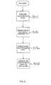
- FIG. 1is a process flow diagram illustrating a general method of implementing an anti-spin control system in accordance with one embodiment of the invention.
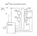
- FIG. 2is a block diagram illustrating a first dual motor system in which the present invention may be implemented, where the field windings are connected in series and the armatures are connected in series.
- FIG. 3is a process flow diagram illustrating one method of shunting power to the slipping motor as shown at block 104 of FIG. 1 within the dual motor system illustrated in FIG. 2.
- FIG. 4is a process flow diagram illustrating one method of resuming to dual motor operation as shown at block 110 of FIG. 1 within the dual motor system illustrated in FIG. 2.
- FIG. 5is a block diagram illustrating a second dual motor system in which the present invention may be implemented, where the field windings are connected in parallel and the armatures are connected in series.
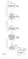
- FIG. 6is a process flow diagram illustrating one method of shunting power to the slipping motor as shown at block 104 of FIG. 1 within the dual motor system illustrated in FIG. 5.
- FIG. 7is a process flow diagram illustrating one method of resuming to dual motor operation as shown at block 110 of FIG. 1 within the dual motor system illustrated in FIG. 5.
- FIG. 8is a block diagram illustrating a third dual motor system in which the present invention may be implemented, where the armatures are connected in series and a separate independent field drive amplifier is connected to each of the parallel connected field windings.
- FIG. 9is a process flow diagram illustrating one method of detecting a recovery event indicating that the shunted motor of the third embodiment illustrated in FIG. 8 may be re-engaged.
- the present inventionprovides anti-spin control for a motor drive system having two or more series connected shunt wound direct current electric motors having separately excited armature and field windings. That is, the armatures of the two or more motors are connected in series. As will be discussed in more detail below, the field windings from the different motors may be connected in series, in parallel or independently. As will be described with reference to the following figures, the present invention enables detection and recovery from a single wheel spin in a vehicle in which two or more driven wheels are each connected to a separate electric motor.
- a controllerresponds by shunting the current around the offending motor (e.g., with a small relay). The offending motor will quickly lose back EMF for lack of field flux. With the reduction of EMF from the now shunted motor, the increased voltage on the remaining motor will allow substantially increased armature current and thus increased torque.
- the shunt relayis de-activated and power is restored to both field coils so that both motors can produce torque. This allows the vehicle to move past the obstacle, hole or other low friction event and return to normal dual motor drive.
- FIG. 1is a process flow diagram illustrating a general method of implementing an anti-spin control system in accordance with one embodiment of the invention.
- a single wheel spinis detected at block 102 in order to determine when to deactivate one of the motors.
- the “slipping motor”may then be identified.
- powere.g., field power
- the motorsare independently excited, power may be shunted by eliminating either armature current or field current in the identified motor. In the following described embodiment, the field current is eliminated.
- a drive algorithmis engaged for the non-slipping motor(s) at block 106 .
- both armature and field currentare supplied to the remaining motors.
- the systemwaits for or detects appropriate conditions to determine when to re-engage the shunted motor as shown at block 108 .
- the vehiclemay then resume to normal dual motor operation at block 110 in response to this recovery event. More particularly, the current that has been eliminated from the slipping motor is now restored.
- FIG. 2, FIG. 5, and FIG. 8illustrate several possible embodiments of a dual motor drive system in which the anti-spin control may be implemented.
- the back EMF of the spinning motoris reduced such that voltage and therefore torque can be restored to the remaining motors.
- the anti-spin controlmay be implemented by adjusting the current across either the armature or the field winding of the “spinning” motor.
- elimination and recovery from a “single wheel spin”is performed through the elimination and restoration of field current in the “spinning motor”.
- FIG. 2 and FIG. 5illustrate motor drive systems employing shunt type motors having armature and field coils which are independently excited by a source of voltage to generate armature and field currents.
- FIG. 2is a block diagram illustrating a first dual motor system in which the present invention may be implemented.
- a source of DC voltage 202e.g., battery
- armatures 204 and 206 associated with the two motorsare connected in series to the voltage source 202 through an armature controller to provide independent control of the motor armatures 204 and 206 .
- motor field windings 208 and 210are coupled to the armatures 204 and 206 and connected to the source of voltage 202 through a field winding controller to provide control of the motor field windings 208 and 210 independent of the armatures 204 and 206 .
- the armature controller and the field winding controllermay be implemented separately, they are preferably implemented in a single controller 212 having a single high power amplifier for the armatures 204 and 206 .
- FIG. 2It is important to note that in the first dual motor system illustrated in FIG. 2, the field windings 208 and 210 are connected in series and each of the field windings 208 and 210 has an associated relay, 212 and 214 , respectively. As described above with reference to block 104 of FIG. 1, the current in the slipping motor is shunted. More particularly, in this embodiment, the field current is eliminated through the use of a relay.
- FIG. 3 and FIG. 4together illustrate a method of shunting and restoring power, respectively, while preventing arching of the relay contacts.
- FIG. 3is a process flow diagram illustrating one method of shunting power to the slipping motor as shown at block 104 of FIG. 1 within the dual motor system illustrated in FIG. 2.
- the field currentis eliminated in the identified motor. Since the field windings 208 and 210 are connected in series, the current flowing through field windings 208 and 210 is identical when the relays 212 and 214 are open, as shown in FIG. 2.
- the relay around the field windings of the slipping motormust be closed.
- the value of the field current flowing through the field coils of the motorsis set to zero at block 302 .
- the shunted motormay be re-engaged.
- the current in the shunted motoris re-established in response to a recovery event.
- the field current flowing through the shunted motoris restored.
- FIG. 4is a process flow diagram illustrating one method of resuming to dual motor operation as shown at block 110 of FIG. 1 within the dual motor system illustrated in FIG. 2.
- the field current commandis set to zero at block 402 to set a desired field current flowing through the field coils of the motors to zero.
- the present inventiondetects that the field current is substantially zero.
- the relay around the previously slipping motoris opened at block 406 .
- the field current commandis then set back to the previous value at block 408 . Since the relay is now open, the current flows through the field windings of the previously slipping motor.
- FIG. 5is a block diagram illustrating a second dual motor system in which the present invention may be implemented.
- field windings 502 and 504are connected in parallel rather than in series.
- the field windings 502 and 504 of both motorshave an associated relay 506 and 508 , respectively.
- the relays 506 and 508remain closed.
- the appropriate relay 506 or 508is opened.
- FIG. 6 and FIG. 7together illustrate a method of shunting and restoring power, respectively, while preventing arching of the relay contacts.
- FIG. 6is a process flow diagram illustrating one method of shunting power to the slipping motor as shown at block 104 of FIG. 1 within the dual motor system illustrated in FIG. 5. Since the current will be set to zero and then restored, it may be desirable to ascertain a value of the field current flowing through the field coils of the motors. In order to eliminate the field current in the slipping motor, the field current flowing through the field coils of the motors is reduced to substantially zero. As shown at block 602 , this may be accomplished by setting a field current command to zero, where the field current command indicates a desired field current flowing through the field coils of the motors.
- the relay around the slipping motoris opened at block 606 .
- the current flowing through the field windings of the motorsis divided among the field windings 502 and 504 .
- the current(e.g., via the field current command) is reduced by this amount in order to maintain previous current levels in the non-slipping motor(s).
- the field current commandis set back to one half the previous field current value at block 608 .
- the field currentwill be reduced by (1/the number of motors) prior to setting the field current at block 608 .
- the currentwill be (1-1/the number of motors)*previous field current value. For example, where there are three motors, the amount of current will be reduced by one-third of the previous field current value.
- FIG. 7is a process flow diagram illustrating one method of resuming to dual motor operation as shown at block 110 of FIG. 1 within the dual motor system illustrated in FIG. 5.
- the relayIn order to cause field current to flow through the previously slipping motor, the relay is closed to allow field current in the previously slipping motor at block 702 .
- the field current commandis then set back to the previous value of the field current at 704 . In other words, the field current is increased to its previous value to accommodate the previously slipping motor. It is important to note that recovery in the second embodiment does not require shutting down the field a second time. This is preferable since each shutdown causes a torque loss and noticeable bump.
- FIG. 8is a block diagram illustrating a third dual motor system in which the present invention may be implemented.
- field windings 802 and 804 of the motorsare connected in parallel and each of the motors has a separate associated field amplifier (not shown).
- the controller 212includes an independent field amplifier for each of the field windings 802 and 804 .
- each of the field windings 802 and 804has independent control and therefore no field shunting relays are required.
- a field current command associated with the slipping motoris set to substantially zero.
- the field current commandis set to its previous value. Unlike the previous two embodiments, there is no complete loss of torque during activation or de-activation of the anti-spin system and no mechanical parts to fail or delay activation/de-activation.
- One slip detection mechanismis based on the relative voltage drop across the different motors. More specifically, during normal operation, the applied voltage across each of the motors should be approximately identical. For instance, in a dual motor system, the voltage across a single motor should be approximately one half the total applied voltage (assuming they are identical motors). However, when one of the motors slips, the voltage across this motor will be greater than a particular threshold voltage. Of course, there may be other reasons for having different voltage drops across the motors as well. Most notably, in the event of a non-slipping turn, the wheels will be rotating at different speeds, and thus, the voltage drops across motors will be different as a function of the tightest permissible turning radius.
- a wheelis determined to be slipping when V>1 ⁇ 2 Vtot+0.25Vtot where Vtot is the total motor voltage across all of the motors and 0.25Vtot functions as a voltage range that defines a slipping motor condition.
- a threshold voltagemay be set over which it is assumed that varies with the relative turning radius of the wheels associated with the motors. This voltage range may be programmable and may reflect the relative turning radius of the two wheels, as described above.
- the voltage V across a single motorshould be approximately 1 ⁇ 2 Vtot, but may rise to 1 ⁇ 2Vtot+0.25Vtot.
- the voltage Vexceeds this threshold amount, the wheel is determined to be slipping. This method is ideal in instances where the wheels have a long turning radius and therefore the motors run at approximately the same speed during turns of the wheels.
- one or more angle sensorsmay be used to ascertain a relative angle of rotation of the two wheels to ascertain the appropriate voltage range and therefore the threshold voltage.
- the voltagemay be monitored between the motor armatures with respect to ground.
- the filtered Controller output voltageis subtracted from the measured battery voltage with the result equal to the total voltage applied across the two motors.
- the voltage between the armaturesis measured with respect to battery ground and the filtered Controller output voltage is subtracted, with the result being the voltage across a single motor.
- the pulse width modulation (PWM) appliedcan be used to determine motor voltage.
- An alternative approach to detecting a slipping motorincludes the detection of a specific rate of acceleration or increased acceleration rate.
- the acceleration rate, or difference in acceleration ratesmay be estimated through the calculation of the derivative of the differences between the velocities of the motors with respect to time.
- the first derivative of the differences between the applied motor voltagesrepresents the rate of velocity difference between the motors.
- the velocitiesmay be sampled over time to determine the change in velocity over time. For instance, the velocity of the motors may be sampled every 10 milliseconds. The velocity of the motors may be obtained, for example, through the use of speed sensors in each wheel. When one motor slips, the acceleration rate changes dramatically and creates a definitive signal that represents wheel slip.
- the speed of the motormay be used to determine whether motor slip is occurring.
- the speedmay provide direct feedback to motor slip.
- the speed of the motorsmay be obtained through the use of speed sensors coupled to the wheels of the vehicle or through sampling motor voltage or applied currents. When motor armature resistance is known, motor speed can be estimated through a calculated motor model.
- Another approach to detection of a slipping motorincludes ascertaining the speed of the motors. More particularly, the speed of two or more motors may be compared to determine if wheel slip is occurring, since the speed of a slipping motor will be much faster than that of the other non-slipping motor.
- a motor modelmay be used to determine motor speed. Armature current, applied voltage and field current in each motor may be measured or calculated from measurements and input into this motor model to ascertain various motor speeds. Accordingly, any of the above mechanisms may be used to detect a wheel slip as well as identify the motor responsible for the wheel slip.
- Various recovery eventsmay be used to determine the appropriate conditions for re-engaging the shunted motor.
- the present inventionpreferably detects that the vehicle has moved in the desired direction. For instance, the movement of the vehicle for a specified period of time or distance could be ascertained. This would indicate a regain of traction and after some distance, it could be assumed that traction could be restored to both wheels.
- Other methods for detecting such movementinclude, but are not limited to, detecting a reduction in armature current in one of the motors.
- voltage and current datamay be input into a motor model to detect a speed of the previously slipping motor to establish whether the speed of the motor is increasing.
- speed sensorsmay be used to determine the speeds of various motors.
- the movement of the vehicleis detected.
- a user-initiated eventsuch as a return of the throttle in the vehicle to neutral or initiation of braking could also be used as recovery events to initiate the recovery of the vehicle into normal dual motor operation.
- a mere lapse of a predetermined period of timemay be useful, although not preferable, in determining the movement of the vehicle.
- FIG. 9illustrates one method of detecting a recovery event indicating that the shunted motor of the third embodiment illustrated in FIG. 8 may be re-engaged. More particularly, in a system having two or more field amplifiers, the offending motor's field could be pulsed on periodically to allow detection of its back EMF and thus its motor speed. If the detected motor speed is substantially the same as the motor with traction, then both motors would be re-engaged. Thus, at block 902 , the field coils of the previously slipping motor are pulsed. The speed of the motor is then detected via the pulsed field coils. The speed of another one of the motors is detected at block 906 . It is next determined whether the speeds of the two motors are substantially equivalent at block 908 . If the speeds of the two motors are determined to be substantially equivalent at block 910 , a recovery event is triggered at block 912 . Otherwise, the field coils of the offending motor could continue to be pulsed on periodically until a recovery event is established.
- the present inventionprovides automatic detection as well as automatic anti-spin engagement. However, the present invention may also inform an operator of the spinning wheel condition by providing an indicator (e.g., light, beeper, display) of the detected condition. The operator may then initiate the anti-spin control manually.
- an indicatore.g., light, beeper, display
- the controller of the present inventionmay generally be implemented on any suitable computer system (e.g., microprocessor).
- the present inventionmay be implemented as computer-readable instructions stored on any suitable computer-readable media.
Landscapes
- Engineering & Computer Science (AREA)
- Life Sciences & Earth Sciences (AREA)
- Sustainable Development (AREA)
- Sustainable Energy (AREA)
- Power Engineering (AREA)
- Transportation (AREA)
- Mechanical Engineering (AREA)
- Electric Propulsion And Braking For Vehicles (AREA)
Abstract
Description
- This application claims priority of provisional U.S. patent application Ser. No. 60/203,423, filed May 10, 2000, entitled “Anti-Spin Control for a Separately Excited Motor Drive System” which is incorporated by reference.[0001]
- 1. Field of the Invention[0002]
- The present invention relates to vehicles in which two or more driven wheels are each connected to an individual separately excited DC motor yet driven by a single controller. More particularly, the present invention relates to methods and apparatus for detecting, eliminating and recovering from a condition in which a single wheel loses contact with the ground or spins on a low friction surface.[0003]
- 2. Description of the Related Art[0004]
- Many electric vehicles have unique performance requirements that pose difficult obstacles to the design of control systems that are used to control the vehicles. For instance, aerial platforms (e.g., scissor lifts) and tuggers used to tow luggage within airports are typically difficult to maneuver due to the potentially large and uneven weight distribution, as well as the proportions of the vehicle. In order to increase the control with which these vehicles are operated and provide increased traction, separate motors are often used to independently drive wheels on the left and right sides of the vehicle.[0005]
- In an electric motor vehicle controlled by two or more DC motors connected in series, there are many potentially undesirable environmental obstacles that can prevent normal operation of the vehicle. As one example, when the vehicle is driven into a pothole or over a ramp, one of the wheels may lose contact with the ground and spin, making it difficult if not impossible to steer the vehicle out of the pothole. As another example, driving over ice or other low friction surface may cause one of the wheels to spin uncontrollably. As the offending motor speeds up it produces increased back Electro-Motive Force (EMF). As the EMF increases, it robs the other motor of applied voltage. As a result, the motor current decreases and a total torque produced by both motors decreases. This often leads to a stalled vehicle or roll-back.[0006]
- Drive systems of electric vehicles such as aerial platforms often employ dual motors with a single controller to save costs while providing increased traction. However, in those systems that do attempt to resolve the spinning wheel problem, the motors are connected in parallel or to separate controllers, increasing the system cost. Moreover, many such systems require that the operator detect the spinning wheel problem as well as manually initiate an anti-spin control mechanism to alleviate the spinning wheel problem. Accordingly, there are continuing efforts to provide improved control mechanisms that facilitate detecting, eliminating and recovering from a single wheel spin in a vehicle in which two or more driven wheels are each connected to an electric motor.[0007]
- The present invention enables the performance of electric motors having armature and field coils that are independently excited by a source of voltage, in which the armature coils are connected in series, to be controlled by a single controller. Since each electric motor has armature and field coils that are independently excited by a single source of voltage, power around either the armature or field coils may be separately shunted. Using such a shunting mechanism, once a “single wheel spin” is detected, recovery from the single wheel spin may be performed.[0008]
- In accordance with one aspect of the invention, methods and apparatus for controlling performance of electric motors in a system having two or more electric motors are disclosed. The motors are adapted for being coupled to two or more wheels of an electric vehicle, where each of the electric motors include armature and field coils which are independently excited by a source of voltage to generate armature and field currents. In addition, the armatures are connected in series to the voltage source. The methods and apparatus include detecting a condition in the system indicating that one of the wheels is slipping, reducing power delivered to one of the motors that is associated with the slipping wheel in response to the detection of the condition, providing power to the one or more motors that are not associated with the slipping wheel after the power delivered to the motor associated with the slipping wheel is reduced, and restoring the power delivered to the one of the motors associated with the slipping wheel in response to a recovery event.[0009]
- In accordance with another aspect of the invention, a condition in the system is detected to ascertain when to deactivate one of the motors. One of the motors to deactivate is identified when the condition is detected. Current in the identified motor is then eliminated. The current may be armature current or field current. Armature current and field current are then provided to the one or more motors that are not identified as one of the motors to deactivate after the current is eliminated in the identified motor. The current in the identified motor is then restored in response to a recovery event.[0010]
- A recovery event may be defined by a variety of different events. For example, a recovery event may include the detection of movement of the vehicle in a desired direction, movement of the vehicle for a specified period of time, and/or movement of the vehicle for a specified distance. Similarly, a recovery event may be a lapse of a predetermined period of time or a user-initiated event such as the return of a throttle in the vehicle to neutral or initiation of braking of the vehicle.[0011]
- FIG. 1 is a process flow diagram illustrating a general method of implementing an anti-spin control system in accordance with one embodiment of the invention.[0012]
- FIG. 2 is a block diagram illustrating a first dual motor system in which the present invention may be implemented, where the field windings are connected in series and the armatures are connected in series.[0013]
- FIG. 3 is a process flow diagram illustrating one method of shunting power to the slipping motor as shown at block[0014]104 of FIG. 1 within the dual motor system illustrated in FIG. 2.
- FIG. 4 is a process flow diagram illustrating one method of resuming to dual motor operation as shown at[0015]
block 110 of FIG. 1 within the dual motor system illustrated in FIG. 2. - FIG. 5 is a block diagram illustrating a second dual motor system in which the present invention may be implemented, where the field windings are connected in parallel and the armatures are connected in series.[0016]
- FIG. 6 is a process flow diagram illustrating one method of shunting power to the slipping motor as shown at block[0017]104 of FIG. 1 within the dual motor system illustrated in FIG. 5.
- FIG. 7 is a process flow diagram illustrating one method of resuming to dual motor operation as shown at[0018]
block 110 of FIG. 1 within the dual motor system illustrated in FIG. 5. - FIG. 8 is a block diagram illustrating a third dual motor system in which the present invention may be implemented, where the armatures are connected in series and a separate independent field drive amplifier is connected to each of the parallel connected field windings.[0019]
- FIG. 9 is a process flow diagram illustrating one method of detecting a recovery event indicating that the shunted motor of the third embodiment illustrated in FIG. 8 may be re-engaged.[0020]
- In the following description, numerous specific details are set forth in order to provide a thorough understanding of the present invention. It will be apparent, however, to one skilled in the art, that the present invention may be practiced without some or all of these specific details. In other instances, well known process steps have not been described in detail in order not to unnecessarily obscure the present invention.[0021]
- The present invention provides anti-spin control for a motor drive system having two or more series connected shunt wound direct current electric motors having separately excited armature and field windings. That is, the armatures of the two or more motors are connected in series. As will be discussed in more detail below, the field windings from the different motors may be connected in series, in parallel or independently. As will be described with reference to the following figures, the present invention enables detection and recovery from a single wheel spin in a vehicle in which two or more driven wheels are each connected to a separate electric motor.[0022]
- In the event that a single wheel loses contact with the ground or spins on a low friction surface, a sensed voltage swings beyond normal limits as the offending motor speeds up and produces increased back EMF. As the EMF increases, it robs the other motor of applied voltage, the motor current decreases and a total torque produced by both motors decreases. This often leads to a stalled vehicle or roll-back. Thus, in accordance with the present invention, a controller responds by shunting the current around the offending motor (e.g., with a small relay). The offending motor will quickly lose back EMF for lack of field flux. With the reduction of EMF from the now shunted motor, the increased voltage on the remaining motor will allow substantially increased armature current and thus increased torque. This in turn will allow the vehicle to continue to move or restrain roll-back. After movement is detected or some time has elapsed, the shunt relay is de-activated and power is restored to both field coils so that both motors can produce torque. This allows the vehicle to move past the obstacle, hole or other low friction event and return to normal dual motor drive.[0023]
- FIG. 1 is a process flow diagram illustrating a general method of implementing an anti-spin control system in accordance with one embodiment of the invention. First, a single wheel spin is detected at[0024]
block 102 in order to determine when to deactivate one of the motors. When this condition is detected, the “slipping motor” may then be identified. Next, power (e.g., field power) is shunted around the slipping motor at block104. More particularly, since the motors are independently excited, power may be shunted by eliminating either armature current or field current in the identified motor. In the following described embodiment, the field current is eliminated. After the current in the field of the offending motor is eliminated, a drive algorithm is engaged for the non-slipping motor(s) atblock 106. In other words, both armature and field current are supplied to the remaining motors. Next, the system waits for or detects appropriate conditions to determine when to re-engage the shunted motor as shown atblock 108. The vehicle may then resume to normal dual motor operation atblock 110 in response to this recovery event. More particularly, the current that has been eliminated from the slipping motor is now restored. - Embodiments Used to Shunt and Restore Power to a Slipping Motor[0025]
- FIG. 2, FIG. 5, and FIG. 8 illustrate several possible embodiments of a dual motor drive system in which the anti-spin control may be implemented. In the following described embodiments, the back EMF of the spinning motor is reduced such that voltage and therefore torque can be restored to the remaining motors. More particularly, the anti-spin control may be implemented by adjusting the current across either the armature or the field winding of the “spinning” motor. However, in the embodiments described with reference to the following figures, elimination and recovery from a “single wheel spin” is performed through the elimination and restoration of field current in the “spinning motor”. Although armature current rather than field current may be eliminated, it is preferable to eliminate field current since the armature current levels would be large in comparison to the required field current levels. Moreover, the substantial armature current would require a large relay, increasing the cost of the resulting system. FIG. 2 and FIG. 5 illustrate motor drive systems employing shunt type motors having armature and field coils which are independently excited by a source of voltage to generate armature and field currents.[0026]
- First Embodiment[0027]
- FIG. 2 is a block diagram illustrating a first dual motor system in which the present invention may be implemented. As shown, a source of DC voltage[0028]202 (e.g., battery) is provided. In addition,
armatures voltage source 202 through an armature controller to provide independent control of themotor armatures motor field windings 208 and210 are coupled to thearmatures voltage 202 through a field winding controller to provide control of themotor field windings 208 and210 independent of thearmatures single controller 212 having a single high power amplifier for thearmatures - It is important to note that in the first dual motor system illustrated in FIG. 2, the[0029]
field windings 208 and210 are connected in series and each of thefield windings 208 and210 has an associated relay,212 and214, respectively. As described above with reference to block104 of FIG. 1, the current in the slipping motor is shunted. More particularly, in this embodiment, the field current is eliminated through the use of a relay. FIG. 3 and FIG. 4 together illustrate a method of shunting and restoring power, respectively, while preventing arching of the relay contacts. - FIG. 3 is a process flow diagram illustrating one method of shunting power to the slipping motor as shown at block[0030]104 of FIG. 1 within the dual motor system illustrated in FIG. 2. In this embodiment, the field current is eliminated in the identified motor. Since the
field windings 208 and210 are connected in series, the current flowing throughfield windings 208 and210 is identical when therelays block 304, the relay around the field coils of the slipping motor is closed at block306. The field current command is then set back to its previous value atblock 308. Since the relay of the slipping motor is closed, the current will now flow through the path of least resistance, and the field current of the slipping motor will therefore be substantially zero. Since the relay of the non-slipping motor remains open, the field current flows through the field windings of the non-slipping motor. - Once the event that caused the motor to slip is over, the shunted motor may be re-engaged. In other words, the current in the shunted motor is re-established in response to a recovery event. Thus, in the embodiment illustrated in FIG. 2, the field current flowing through the shunted motor is restored.[0031]
- FIG. 4 is a process flow diagram illustrating one method of resuming to dual motor operation as shown at[0032]
block 110 of FIG. 1 within the dual motor system illustrated in FIG. 2. The field current command is set to zero atblock 402 to set a desired field current flowing through the field coils of the motors to zero. Next, atblock 404 the present invention detects that the field current is substantially zero. When the field current is substantially zero, the relay around the previously slipping motor is opened at block406. The field current command is then set back to the previous value atblock 408. Since the relay is now open, the current flows through the field windings of the previously slipping motor. - Second Embodiment[0033]
- FIG. 5 is a block diagram illustrating a second dual motor system in which the present invention may be implemented. In this embodiment,[0034]
field windings 502 and504 are connected in parallel rather than in series. Moreover, thefield windings 502 and504 of both motors have an associatedrelay 506 and508, respectively. As shown, during normal operation of the vehicle, therelays 506 and508 remain closed. In order to eliminate field current flowing through the slipping motor, theappropriate relay 506 or508 is opened. FIG. 6 and FIG. 7 together illustrate a method of shunting and restoring power, respectively, while preventing arching of the relay contacts. - FIG. 6 is a process flow diagram illustrating one method of shunting power to the slipping motor as shown at block[0035]104 of FIG. 1 within the dual motor system illustrated in FIG. 5. Since the current will be set to zero and then restored, it may be desirable to ascertain a value of the field current flowing through the field coils of the motors. In order to eliminate the field current in the slipping motor, the field current flowing through the field coils of the motors is reduced to substantially zero. As shown at
block 602, this may be accomplished by setting a field current command to zero, where the field current command indicates a desired field current flowing through the field coils of the motors. Once it is detected that the field current is substantially zero atblock 604, the relay around the slipping motor is opened at block606. During normal operation of the vehicle, the current flowing through the field windings of the motors is divided among thefield windings 502 and504. Thus, when field current no longer flows through one of the motors, the current (e.g., via the field current command) is reduced by this amount in order to maintain previous current levels in the non-slipping motor(s). Since in this example there are two motors, the field current command is set back to one half the previous field current value atblock 608. Of course, if more than two motors are used, the field current will be reduced by (1/the number of motors) prior to setting the field current atblock 608. In other words, the current will be (1-1/the number of motors)*previous field current value. For example, where there are three motors, the amount of current will be reduced by one-third of the previous field current value. - FIG. 7 is a process flow diagram illustrating one method of resuming to dual motor operation as shown at[0036]
block 110 of FIG. 1 within the dual motor system illustrated in FIG. 5. In order to cause field current to flow through the previously slipping motor, the relay is closed to allow field current in the previously slipping motor atblock 702. The field current command is then set back to the previous value of the field current at704. In other words, the field current is increased to its previous value to accommodate the previously slipping motor. It is important to note that recovery in the second embodiment does not require shutting down the field a second time. This is preferable since each shutdown causes a torque loss and noticeable bump. - Third Embodiment[0037]
- FIG. 8 is a block diagram illustrating a third dual motor system in which the present invention may be implemented. In this embodiment,[0038]
field windings 802 and804 of the motors are connected in parallel and each of the motors has a separate associated field amplifier (not shown). In this embodiment, thecontroller 212 includes an independent field amplifier for each of thefield windings 802 and804. Thus, each of thefield windings 802 and804 has independent control and therefore no field shunting relays are required. - In order to eliminate field current in the slipping motor, a field current command associated with the slipping motor is set to substantially zero. Similarly, once recovery of power to both motors is desired, the field current command is set to its previous value. Unlike the previous two embodiments, there is no complete loss of torque during activation or de-activation of the anti-spin system and no mechanical parts to fail or delay activation/de-activation.[0039]
- Detection of Slipping Motor[0040]
- There are various ways to detect a “slipping motor” condition. One slip detection mechanism is based on the relative voltage drop across the different motors. More specifically, during normal operation, the applied voltage across each of the motors should be approximately identical. For instance, in a dual motor system, the voltage across a single motor should be approximately one half the total applied voltage (assuming they are identical motors). However, when one of the motors slips, the voltage across this motor will be greater than a particular threshold voltage. Of course, there may be other reasons for having different voltage drops across the motors as well. Most notably, in the event of a non-slipping turn, the wheels will be rotating at different speeds, and thus, the voltage drops across motors will be different as a function of the tightest permissible turning radius. For instance, the relative turning radius of an outside wheel with respect to an inside wheel may be determined as follows: Vout/Vin=(L+W)/L where L is the length of the vehicle and W is the width of the vehicle. When the turning radius of one wheel is within 25 percent of the turning radius of another wheel, a wheel is determined to be slipping when V>½ Vtot+0.25Vtot where Vtot is the total motor voltage across all of the motors and 0.25Vtot functions as a voltage range that defines a slipping motor condition. Thus, a threshold voltage may be set over which it is assumed that varies with the relative turning radius of the wheels associated with the motors. This voltage range may be programmable and may reflect the relative turning radius of the two wheels, as described above. Thus, in a dual motor system in which the maximum relative turning radius between the wheels is 25 percent, the voltage V across a single motor should be approximately ½ Vtot, but may rise to ½Vtot+0.25Vtot. When the voltage V exceeds this threshold amount, the wheel is determined to be slipping. This method is ideal in instances where the wheels have a long turning radius and therefore the motors run at approximately the same speed during turns of the wheels.[0041]
- Alternatively, rather than using a fixed threshold value, one or more angle sensors may be used to ascertain a relative angle of rotation of the two wheels to ascertain the appropriate voltage range and therefore the threshold voltage.[0042]
- In order to ascertain the voltage across a single motor, the voltage may be monitored between the motor armatures with respect to ground. The filtered Controller output voltage is subtracted from the measured battery voltage with the result equal to the total voltage applied across the two motors. The voltage between the armatures is measured with respect to battery ground and the filtered Controller output voltage is subtracted, with the result being the voltage across a single motor. In a half-bridge power topology, the pulse width modulation (PWM) applied can be used to determine motor voltage.[0043]
- An alternative approach to detecting a slipping motor includes the detection of a specific rate of acceleration or increased acceleration rate. Thus, when the acceleration of one of the motors exceeds a maximum acceleration rate, this may indicate a slipping motor condition. This method may be used for wheels of any turning radius. The acceleration rate, or difference in acceleration rates, may be estimated through the calculation of the derivative of the differences between the velocities of the motors with respect to time. Moreover, the first derivative of the differences between the applied motor voltages represents the rate of velocity difference between the motors. Alternatively, the velocities may be sampled over time to determine the change in velocity over time. For instance, the velocity of the motors may be sampled every 10 milliseconds. The velocity of the motors may be obtained, for example, through the use of speed sensors in each wheel. When one motor slips, the acceleration rate changes dramatically and creates a definitive signal that represents wheel slip.[0044]
- In accordance with another approach to detecting a slipping motor, the speed of the motor may be used to determine whether motor slip is occurring. The speed may provide direct feedback to motor slip. As described above, the speed of the motors may be obtained through the use of speed sensors coupled to the wheels of the vehicle or through sampling motor voltage or applied currents. When motor armature resistance is known, motor speed can be estimated through a calculated motor model.[0045]
- Another approach to detection of a slipping motor includes ascertaining the speed of the motors. More particularly, the speed of two or more motors may be compared to determine if wheel slip is occurring, since the speed of a slipping motor will be much faster than that of the other non-slipping motor. For example, a motor model may be used to determine motor speed. Armature current, applied voltage and field current in each motor may be measured or calculated from measurements and input into this motor model to ascertain various motor speeds. Accordingly, any of the above mechanisms may be used to detect a wheel slip as well as identify the motor responsible for the wheel slip.[0046]
- Recovery Event Used to Initiate Restoration of Power to Previously Slipping Motor[0047]
- Various recovery events may be used to determine the appropriate conditions for re-engaging the shunted motor. The present invention preferably detects that the vehicle has moved in the desired direction. For instance, the movement of the vehicle for a specified period of time or distance could be ascertained. This would indicate a regain of traction and after some distance, it could be assumed that traction could be restored to both wheels. Other methods for detecting such movement include, but are not limited to, detecting a reduction in armature current in one of the motors. Similarly, voltage and current data may be input into a motor model to detect a speed of the previously slipping motor to establish whether the speed of the motor is increasing. Moreover, speed sensors may be used to determine the speeds of various motors. When the speeds of the previously slipping motor and another motor are determined to be within a specified range (and therefore approximately the same), the movement of the vehicle is detected. As another example, a user-initiated event such as a return of the throttle in the vehicle to neutral or initiation of braking could also be used as recovery events to initiate the recovery of the vehicle into normal dual motor operation. Of course, a mere lapse of a predetermined period of time may be useful, although not preferable, in determining the movement of the vehicle.[0048]
- FIG. 9 illustrates one method of detecting a recovery event indicating that the shunted motor of the third embodiment illustrated in FIG. 8 may be re-engaged. More particularly, in a system having two or more field amplifiers, the offending motor's field could be pulsed on periodically to allow detection of its back EMF and thus its motor speed. If the detected motor speed is substantially the same as the motor with traction, then both motors would be re-engaged. Thus, at[0049]
block 902, the field coils of the previously slipping motor are pulsed. The speed of the motor is then detected via the pulsed field coils. The speed of another one of the motors is detected atblock 906. It is next determined whether the speeds of the two motors are substantially equivalent atblock 908. If the speeds of the two motors are determined to be substantially equivalent atblock 910, a recovery event is triggered atblock 912. Otherwise, the field coils of the offending motor could continue to be pulsed on periodically until a recovery event is established. - The present invention provides automatic detection as well as automatic anti-spin engagement. However, the present invention may also inform an operator of the spinning wheel condition by providing an indicator (e.g., light, beeper, display) of the detected condition. The operator may then initiate the anti-spin control manually.[0050]
- The controller of the present invention may generally be implemented on any suitable computer system (e.g., microprocessor). In addition, the present invention may be implemented as computer-readable instructions stored on any suitable computer-readable media.[0051]
- Although illustrative embodiments and applications of this invention are shown and described herein, many variations and modifications are possible which remain within the concept, scope, and spirit of the invention, and these variations would become clear to those of ordinary skill in the art after perusal of this application. For instance, although the specification has described a dual motor system, more than two motors may be used. Moreover, although shunt relays are shown to be connected to the field windings in some of the above-described embodiments, it is also possible to shunt the armature current. Accordingly, the present embodiments are to be considered as illustrative and not restrictive, and the invention is not to be limited to the details given herein, but may be modified within the scope and equivalents of the appended claims.[0052]
Claims (49)
Priority Applications (1)
| Application Number | Priority Date | Filing Date | Title |
|---|---|---|---|
| US09/853,404US6611116B2 (en) | 2000-05-10 | 2001-05-10 | Anti-spin control for a separately excited motor drive system |
Applications Claiming Priority (2)
| Application Number | Priority Date | Filing Date | Title |
|---|---|---|---|
| US20342300P | 2000-05-10 | 2000-05-10 | |
| US09/853,404US6611116B2 (en) | 2000-05-10 | 2001-05-10 | Anti-spin control for a separately excited motor drive system |
Publications (2)
| Publication Number | Publication Date |
|---|---|
| US20020005304A1true US20020005304A1 (en) | 2002-01-17 |
| US6611116B2 US6611116B2 (en) | 2003-08-26 |
Family
ID=26898598
Family Applications (1)
| Application Number | Title | Priority Date | Filing Date |
|---|---|---|---|
| US09/853,404Expired - LifetimeUS6611116B2 (en) | 2000-05-10 | 2001-05-10 | Anti-spin control for a separately excited motor drive system |
Country Status (1)
| Country | Link |
|---|---|
| US (1) | US6611116B2 (en) |
Cited By (34)
| Publication number | Priority date | Publication date | Assignee | Title |
|---|---|---|---|---|
| US20030205422A1 (en)* | 2002-05-02 | 2003-11-06 | Oshkosh Truck Corporation | Hybrid vehicle with combustion engine/electric motor drive |
| EP1371516A3 (en)* | 2002-06-11 | 2004-02-25 | General Motors Corporation | Locomotive wheel slip control and method |
| US20040133332A1 (en)* | 2001-01-31 | 2004-07-08 | Oshkosh Truck Corporation | A/C bus assembly for electronic traction vehicle |
| US20050113988A1 (en)* | 2001-12-21 | 2005-05-26 | Oshkosh Truck Corporation | Failure mode operation for an electric vehicle |
| US20050114007A1 (en)* | 2001-12-21 | 2005-05-26 | Oshkosh Truck Corporation | Multi-network control system for a vehicle |
| US20050119806A1 (en)* | 2001-01-31 | 2005-06-02 | Oshkosh Truck Corporation | System and method for braking in an electric vehicle |
| US20050189886A1 (en)* | 2004-02-17 | 2005-09-01 | Railpower Technologies Corp. | Predicting wheel slip and skid in a locomotive |
| US20060071645A1 (en)* | 2004-09-27 | 2006-04-06 | Oshkosh Truck Corporation | Status indicator for an energy storage device for use with an electric vehicle |
| US7040439B2 (en)* | 2002-09-03 | 2006-05-09 | Hitachi, Ltd. | Hybrid car control apparatus |
| US20060106521A1 (en)* | 2004-09-27 | 2006-05-18 | Oshkosh Truck Corporation | System and method for reducing wheel slip and wheel locking in an electric vehicle |
| US20070061059A1 (en)* | 2005-09-14 | 2007-03-15 | Toyota Jidosha Kabushiki Kaisha | Vehicle controller |
| US20070185625A1 (en)* | 1999-07-30 | 2007-08-09 | Oshkosh Truck Corporation | Turret envelope control system and method for a fire fighting vehicle |
| US20070288131A1 (en)* | 2001-01-31 | 2007-12-13 | Oshkosh Truck Corporation | Control system and method for electric vehicle |
| US20070291130A1 (en)* | 2006-06-19 | 2007-12-20 | Oshkosh Truck Corporation | Vision system for an autonomous vehicle |
| EP1894767A1 (en) | 2006-08-31 | 2008-03-05 | Hitachi, Ltd. | Control apparatus for vehicle |
| US20080103662A1 (en)* | 1999-07-30 | 2008-05-01 | Oshkosh Truck Corporation | Concrete placement vehicle control system and method |
| US20090272298A1 (en)* | 2005-11-23 | 2009-11-05 | Lars Borthy Petersen | Use of Pulverized Glass in a Composite Material |
| EP1466775A3 (en)* | 2003-04-10 | 2010-09-15 | Nissan Motor Company Limited | Drive controlling apparatus and method for automotive vehicle |
| WO2010113161A1 (en)* | 2009-03-31 | 2010-10-07 | Yesaiahu Redler | Apparatus and method for optimizing current use during control of multiple motors |
| EP2404778A3 (en)* | 2007-09-18 | 2012-08-08 | Mitsubishi Electric Corporation | Electric train car controlling device |
| US8337352B2 (en) | 2010-06-22 | 2012-12-25 | Oshkosh Corporation | Electromechanical variable transmission |
| US8947531B2 (en) | 2006-06-19 | 2015-02-03 | Oshkosh Corporation | Vehicle diagnostics based on information communicated between vehicles |
| US9114804B1 (en) | 2013-03-14 | 2015-08-25 | Oshkosh Defense, Llc | Vehicle drive and method with electromechanical variable transmission |
| US9651120B2 (en) | 2015-02-17 | 2017-05-16 | Oshkosh Corporation | Multi-mode electromechanical variable transmission |
| US9650032B2 (en) | 2015-02-17 | 2017-05-16 | Oshkosh Corporation | Multi-mode electromechanical variable transmission |
| US9656659B2 (en) | 2015-02-17 | 2017-05-23 | Oshkosh Corporation | Multi-mode electromechanical variable transmission |
| US10421350B2 (en) | 2015-10-20 | 2019-09-24 | Oshkosh Corporation | Inline electromechanical variable transmission system |
| US10578195B2 (en) | 2015-02-17 | 2020-03-03 | Oshkosh Corporation | Inline electromechanical variable transmission system |
| US10584775B2 (en) | 2015-02-17 | 2020-03-10 | Oshkosh Corporation | Inline electromechanical variable transmission system |
| US10982736B2 (en) | 2015-02-17 | 2021-04-20 | Oshkosh Corporation | Multi-mode electromechanical variable transmission |
| US11325595B2 (en)* | 2019-05-24 | 2022-05-10 | Toyota Jidosha Kabushiki Kaisha | Vehicle |
| EP4071022A1 (en)* | 2021-04-06 | 2022-10-12 | Rivian IP Holdings, LLC | Systems and methods for speed control of wheels of a vehicle |
| US11701959B2 (en) | 2015-02-17 | 2023-07-18 | Oshkosh Corporation | Inline electromechanical variable transmission system |
| US12078231B2 (en) | 2015-02-17 | 2024-09-03 | Oshkosh Corporation | Inline electromechanical variable transmission system |
Families Citing this family (9)
| Publication number | Priority date | Publication date | Assignee | Title |
|---|---|---|---|---|
| WO2005097573A2 (en) | 2004-03-30 | 2005-10-20 | Railpower Technologies Corp. | Emission management for a hybrid locomotive |
| US20060012334A1 (en) | 2004-05-17 | 2006-01-19 | Railpower Technologies Corp. | Automated battery cell shunt bypass |
| CA2576871A1 (en) | 2004-08-09 | 2006-02-23 | Railpower Technologies Corp. | Regenerative braking methods for a hybrid locomotive |
| AU2005272903A1 (en) | 2004-08-09 | 2006-02-23 | Railpower Technologies Corp. | Locomotive power train architecture |
| US7565867B2 (en) | 2004-09-03 | 2009-07-28 | Frank Wegner Donnelly | Multiple engine locomotive configuration |
| US7309929B2 (en)* | 2005-04-25 | 2007-12-18 | Railpower Technologies Corporation | Locomotive engine start method |
| WO2007047809A2 (en) | 2005-10-19 | 2007-04-26 | Railpower Technologies Corp. | Design of a large low maintenance battery pack for a hybrid locomotive |
| US7778747B2 (en)* | 2006-08-31 | 2010-08-17 | National Railway Equipment Co. | Adhesion control system for off-highway vehicle |
| US20080288132A1 (en) | 2007-05-16 | 2008-11-20 | General Electric Company | Method of operating vehicle and associated system |
Family Cites Families (3)
| Publication number | Priority date | Publication date | Assignee | Title |
|---|---|---|---|---|
| US3764867A (en)* | 1972-11-14 | 1973-10-09 | Gen Electric | Traction motor speed regulation for propulsion systems providing smooth stepless changes in speed and automatic wheel slip control |
| US5264763A (en)* | 1992-10-29 | 1993-11-23 | Schaeff Inc. | Optimizing system for vehicle traction motors |
| JPH11136811A (en)* | 1997-10-29 | 1999-05-21 | Toyota Autom Loom Works Ltd | Vehicle controller |
- 2001
- 2001-05-10USUS09/853,404patent/US6611116B2/ennot_activeExpired - Lifetime
Cited By (84)
| Publication number | Priority date | Publication date | Assignee | Title |
|---|---|---|---|---|
| US7835838B2 (en) | 1999-07-30 | 2010-11-16 | Oshkosh Corporation | Concrete placement vehicle control system and method |
| US8095247B2 (en) | 1999-07-30 | 2012-01-10 | Oshkosh Corporation | Turret envelope control system and method for a vehicle |
| US20080103662A1 (en)* | 1999-07-30 | 2008-05-01 | Oshkosh Truck Corporation | Concrete placement vehicle control system and method |
| US20070185625A1 (en)* | 1999-07-30 | 2007-08-09 | Oshkosh Truck Corporation | Turret envelope control system and method for a fire fighting vehicle |
| US20070288131A1 (en)* | 2001-01-31 | 2007-12-13 | Oshkosh Truck Corporation | Control system and method for electric vehicle |
| US20050119806A1 (en)* | 2001-01-31 | 2005-06-02 | Oshkosh Truck Corporation | System and method for braking in an electric vehicle |
| US20040133332A1 (en)* | 2001-01-31 | 2004-07-08 | Oshkosh Truck Corporation | A/C bus assembly for electronic traction vehicle |
| US20080059014A1 (en)* | 2001-01-31 | 2008-03-06 | Oshkosh Truck Corporation | System and method for braking in an electric vehicle |
| US7379797B2 (en) | 2001-01-31 | 2008-05-27 | Oshkosh Truck Corporation | System and method for braking in an electric vehicle |
| US7848857B2 (en) | 2001-01-31 | 2010-12-07 | Oshkosh Corporation | System and method for braking in an electric vehicle |
| US7711460B2 (en) | 2001-01-31 | 2010-05-04 | Oshkosh Corporation | Control system and method for electric vehicle |
| US7164977B2 (en) | 2001-01-31 | 2007-01-16 | Oshkosh Truck Corporation | A/C bus assembly for electronic traction vehicle |
| US7254468B2 (en) | 2001-12-21 | 2007-08-07 | Oshkosh Truck Corporation | Multi-network control system for a vehicle |
| US20050113988A1 (en)* | 2001-12-21 | 2005-05-26 | Oshkosh Truck Corporation | Failure mode operation for an electric vehicle |
| US7302320B2 (en) | 2001-12-21 | 2007-11-27 | Oshkosh Truck Corporation | Failure mode operation for an electric vehicle |
| US20080071438A1 (en)* | 2001-12-21 | 2008-03-20 | Oshkosh Truck Corporation | Failure mode operation for an electric vehicle |
| US8000850B2 (en) | 2001-12-21 | 2011-08-16 | Oshkosh Truck Corporation | Failure mode operation for an electric vehicle |
| US20050114007A1 (en)* | 2001-12-21 | 2005-05-26 | Oshkosh Truck Corporation | Multi-network control system for a vehicle |
| US20090194347A1 (en)* | 2002-05-02 | 2009-08-06 | Oshkosh Corporation | Hybrid vehicle with combustion engine/electric motor drive |
| US7520354B2 (en) | 2002-05-02 | 2009-04-21 | Oshkosh Truck Corporation | Hybrid vehicle with combustion engine/electric motor drive |
| US20030205422A1 (en)* | 2002-05-02 | 2003-11-06 | Oshkosh Truck Corporation | Hybrid vehicle with combustion engine/electric motor drive |
| EP1371516A3 (en)* | 2002-06-11 | 2004-02-25 | General Motors Corporation | Locomotive wheel slip control and method |
| US7040439B2 (en)* | 2002-09-03 | 2006-05-09 | Hitachi, Ltd. | Hybrid car control apparatus |
| EP1466775A3 (en)* | 2003-04-10 | 2010-09-15 | Nissan Motor Company Limited | Drive controlling apparatus and method for automotive vehicle |
| US20050189886A1 (en)* | 2004-02-17 | 2005-09-01 | Railpower Technologies Corp. | Predicting wheel slip and skid in a locomotive |
| US7084602B2 (en)* | 2004-02-17 | 2006-08-01 | Railpower Technologies Corp. | Predicting wheel slip and skid in a locomotive |
| US20060106521A1 (en)* | 2004-09-27 | 2006-05-18 | Oshkosh Truck Corporation | System and method for reducing wheel slip and wheel locking in an electric vehicle |
| US7439711B2 (en) | 2004-09-27 | 2008-10-21 | Oshkosh Corporation | Energy storage device including a status indicator |
| US20060071645A1 (en)* | 2004-09-27 | 2006-04-06 | Oshkosh Truck Corporation | Status indicator for an energy storage device for use with an electric vehicle |
| US7937194B2 (en) | 2004-09-27 | 2011-05-03 | Oshkosh Corporation | System and method for reducing wheel slip and wheel locking in an electric vehicle |
| US20070061059A1 (en)* | 2005-09-14 | 2007-03-15 | Toyota Jidosha Kabushiki Kaisha | Vehicle controller |
| US7774122B2 (en)* | 2005-09-14 | 2010-08-10 | Toyota Jidosha Kabushiki Kaisha | Vehicle controller |
| US20090272298A1 (en)* | 2005-11-23 | 2009-11-05 | Lars Borthy Petersen | Use of Pulverized Glass in a Composite Material |
| US8947531B2 (en) | 2006-06-19 | 2015-02-03 | Oshkosh Corporation | Vehicle diagnostics based on information communicated between vehicles |
| US20070291130A1 (en)* | 2006-06-19 | 2007-12-20 | Oshkosh Truck Corporation | Vision system for an autonomous vehicle |
| US8139109B2 (en) | 2006-06-19 | 2012-03-20 | Oshkosh Corporation | Vision system for an autonomous vehicle |
| US9420203B2 (en) | 2006-06-19 | 2016-08-16 | Oshkosh Defense, Llc | Vision system for a vehicle |
| US7663336B2 (en) | 2006-08-31 | 2010-02-16 | Hitachi, Ltd. | Control apparatus for vehicle |
| US20080056687A1 (en)* | 2006-08-31 | 2008-03-06 | Hitachi, Ltd. | Control Apparatus For Vehicle |
| EP1894767A1 (en) | 2006-08-31 | 2008-03-05 | Hitachi, Ltd. | Control apparatus for vehicle |
| EP2404778A3 (en)* | 2007-09-18 | 2012-08-08 | Mitsubishi Electric Corporation | Electric train car controlling device |
| US8280568B2 (en) | 2007-09-18 | 2012-10-02 | Mitsubishi Electric Corporation | Electric train car controlling device |
| WO2010113161A1 (en)* | 2009-03-31 | 2010-10-07 | Yesaiahu Redler | Apparatus and method for optimizing current use during control of multiple motors |
| US8629634B2 (en) | 2010-02-01 | 2014-01-14 | Yesaiahu REDLER | Apparatus and method for optimizing current use during control of multiple motors |
| US8337352B2 (en) | 2010-06-22 | 2012-12-25 | Oshkosh Corporation | Electromechanical variable transmission |
| US10029556B2 (en) | 2010-06-22 | 2018-07-24 | Oshkosh Defense, Llc | Electromechanical variable transmission |
| US10843549B2 (en) | 2010-06-22 | 2020-11-24 | Oshkosh Defense, Llc | Electromechanical variable transmission |
| US10457134B2 (en) | 2010-06-22 | 2019-10-29 | Oshkosh Defense, Llc | Electromechanical variable transmission |
| US8864613B2 (en) | 2010-06-22 | 2014-10-21 | Oshkosh Corporation | Electromechanical variable transmission |
| US9428042B2 (en) | 2010-06-22 | 2016-08-30 | Oshkosh Defense, Llc | Electromechanical variable transmission |
| US11052899B2 (en) | 2013-03-14 | 2021-07-06 | Oshkosh Defense, Llc | Vehicle drive and method with electromechanical variable transmission |
| US11440527B2 (en) | 2013-03-14 | 2022-09-13 | Oshkosh Defense, Llc | Methods and systems for vehicle drive |
| US12214770B2 (en) | 2013-03-14 | 2025-02-04 | Oshkosh Defense, Llc | Drive train for a vehicle |
| US11827207B2 (en) | 2013-03-14 | 2023-11-28 | Oshkosh Defense, Llc | Drive train for a vehicle |
| US9821789B2 (en) | 2013-03-14 | 2017-11-21 | Oshkosh Defense, Llc | Vehicle drive and method with electromechanical variable transmission |
| US11299139B2 (en) | 2013-03-14 | 2022-04-12 | Oshkosh Defense, Llc | Drive train for a vehicle |
| US9452750B2 (en) | 2013-03-14 | 2016-09-27 | Oshkosh Defense, Llc | Methods, systems, and vehicles with electromechanical variable transmission |
| US9114804B1 (en) | 2013-03-14 | 2015-08-25 | Oshkosh Defense, Llc | Vehicle drive and method with electromechanical variable transmission |
| US10315643B2 (en) | 2013-03-14 | 2019-06-11 | Oshkosh Defense, Llc | Methods, systems, and vehicles with electromechanical variable transmission |
| US10392000B2 (en) | 2013-03-14 | 2019-08-27 | Oshkosh Defense, Llc | Vehicle drive and method with electromechanical variable transmission |
| US9132736B1 (en) | 2013-03-14 | 2015-09-15 | Oshkosh Defense, Llc | Methods, systems, and vehicles with electromechanical variable transmission |
| US9376102B1 (en) | 2013-03-14 | 2016-06-28 | Oshkosh Defense, Llc | Vehicle drive and method with electromechanical variable transmission |
| US10160438B2 (en) | 2015-02-17 | 2018-12-25 | Oshkosh Corporation | Multi-mode electromechanical variable transmission |
| US9908520B2 (en) | 2015-02-17 | 2018-03-06 | Oshkosh Corporation | Multi-mode electromechanical variable transmission |
| US12228195B2 (en) | 2015-02-17 | 2025-02-18 | Oshkosh Corporation | Driveline for electrified vehicle |
| US10935112B2 (en) | 2015-02-17 | 2021-03-02 | Oshkosh Corporation | Inline electromechanical variable transmission system |
| US10967728B2 (en) | 2015-02-17 | 2021-04-06 | Oshkosh Corporation | Multi-mode electromechanical variable transmission |
| US10974713B2 (en) | 2015-02-17 | 2021-04-13 | Oshkosh Corporation | Multi-mode electromechanical variable transmission |
| US10982736B2 (en) | 2015-02-17 | 2021-04-20 | Oshkosh Corporation | Multi-mode electromechanical variable transmission |
| US10989279B2 (en) | 2015-02-17 | 2021-04-27 | Oshkosh Corporation | Multi-mode electromechanical variable transmission |
| US11009104B2 (en) | 2015-02-17 | 2021-05-18 | Oshkosh Corporation | Inline electromechanical variable transmission system |
| US9650032B2 (en) | 2015-02-17 | 2017-05-16 | Oshkosh Corporation | Multi-mode electromechanical variable transmission |
| US10584775B2 (en) | 2015-02-17 | 2020-03-10 | Oshkosh Corporation | Inline electromechanical variable transmission system |
| US10578195B2 (en) | 2015-02-17 | 2020-03-03 | Oshkosh Corporation | Inline electromechanical variable transmission system |
| US12078231B2 (en) | 2015-02-17 | 2024-09-03 | Oshkosh Corporation | Inline electromechanical variable transmission system |
| US9651120B2 (en) | 2015-02-17 | 2017-05-16 | Oshkosh Corporation | Multi-mode electromechanical variable transmission |
| US9656659B2 (en) | 2015-02-17 | 2017-05-23 | Oshkosh Corporation | Multi-mode electromechanical variable transmission |
| US11701959B2 (en) | 2015-02-17 | 2023-07-18 | Oshkosh Corporation | Inline electromechanical variable transmission system |
| US11007860B2 (en) | 2015-10-20 | 2021-05-18 | Oshkosh Corporation | Inline electromechanical variable transmission system |
| US10421350B2 (en) | 2015-10-20 | 2019-09-24 | Oshkosh Corporation | Inline electromechanical variable transmission system |
| US11325595B2 (en)* | 2019-05-24 | 2022-05-10 | Toyota Jidosha Kabushiki Kaisha | Vehicle |
| CN115195491A (en)* | 2021-04-06 | 2022-10-18 | 瑞伟安知识产权控股有限公司 | System and method for speed control of wheels of a vehicle |
| EP4071022A1 (en)* | 2021-04-06 | 2022-10-12 | Rivian IP Holdings, LLC | Systems and methods for speed control of wheels of a vehicle |
| US11932117B2 (en) | 2021-04-06 | 2024-03-19 | Rivian Ip Holdings, Llc | Systems and methods for speed control of wheels of a vehicle |
Also Published As
| Publication number | Publication date |
|---|---|
| US6611116B2 (en) | 2003-08-26 |
Similar Documents
| Publication | Publication Date | Title |
|---|---|---|
| US6611116B2 (en) | Anti-spin control for a separately excited motor drive system | |
| JP3383226B2 (en) | Method and apparatus for detecting over-use condition of electric assist steering motor | |
| US6316892B1 (en) | Automatic door control system | |
| US9873451B2 (en) | Motor circuit for electric power assisted steering and method | |
| CN105292094B (en) | Method and device for operating a parking brake of a motor vehicle | |
| US9394739B2 (en) | Window opening-closing control system and window opening-closing control apparatus | |
| US6385522B1 (en) | Brake control apparatus and method | |
| EP0870641B1 (en) | Performance event sensing for control of electric motor driven golf car | |
| JPH0733033A (en) | Power supply relay failure detection device for electric motor drive equipment | |
| US4569411A (en) | Power steering control apparatus | |
| AU687971B2 (en) | Proportional control of a permanent magnet brake | |
| JP3320960B2 (en) | Motor control device | |
| JPH04261396A (en) | Abnormality monitor for step motor | |
| JPH02123903A (en) | Eddy current brake device for vehicles | |
| KR100884822B1 (en) | How to detect failure of solenoid valve | |
| JP2001079041A (en) | Electric wheelchair abnormality detection method | |
| KR20220086991A (en) | Motor Controller and method thereof | |
| EP0641700B1 (en) | Proportional control of a permanent magnet brake | |
| US7392098B2 (en) | Control system | |
| US20070182352A1 (en) | Method and circuit arrangement for the electrical control and/or regulation of the movement of an electrically driven unit | |
| JPH1169865A (en) | Electric motor drive | |
| JP3131109B2 (en) | Steering control device | |
| JP2001352611A (en) | Electric vehicle control device and control method, and electric vehicle using the same | |
| JPH0469002A (en) | Control method for inverter electric vehicle | |
| JPH0993726A (en) | Method for controlling electric rolling stock |
Legal Events
| Date | Code | Title | Description |
|---|---|---|---|
| AS | Assignment | Owner name:CURTIS INSTRUMENTS, INC., CALIFORNIA Free format text:ASSIGNMENT OF ASSIGNORS INTEREST;ASSIGNORS:BACHMAN, MICHAEL;NAHAPETIAN, GEVORG;MAY, BILL;REEL/FRAME:011813/0417;SIGNING DATES FROM 20010428 TO 20010509 | |
| STCF | Information on status: patent grant | Free format text:PATENTED CASE | |
| AS | Assignment | Owner name:BANK OF NEW YORK, AS ADMINISTRATIVE AGENT, THE, NE Free format text:GRANT OF SECURITY INTEREST;ASSIGNOR:CURTIS INSTRUMENTS, INC.;REEL/FRAME:017125/0460 Effective date:20051216 | |
| AS | Assignment | Owner name:THE BANK OF NEW YORK, NEW YORK Free format text:SECURITY INTEREST;ASSIGNOR:CURTIS INSTRUMENTS, INC.;REEL/FRAME:017230/0312 Effective date:20051216 | |
| FPAY | Fee payment | Year of fee payment:4 | |
| FPAY | Fee payment | Year of fee payment:8 | |
| FPAY | Fee payment | Year of fee payment:12 | |
| AS | Assignment | Owner name:TD BANK, N.A., NEW YORK Free format text:SECURITY AGREEMENT;ASSIGNOR:CURTIS INSTRUMENTS, INC.;REEL/FRAME:036151/0428 Effective date:20150707 | |
| AS | Assignment | Owner name:TD BANK, N.A., NEW YORK Free format text:AMENDED AND RESTATED SECURITY AGREEMENT;ASSIGNOR:CURTIS INSTRUMENTS, INC.;REEL/FRAME:050048/0354 Effective date:20190812 | |
| AS | Assignment | Owner name:CURTIS INSTRUMENTS, INC., NEW YORK Free format text:RELEASE BY SECURED PARTY;ASSIGNOR:TD BANK, N.A.;REEL/FRAME:058597/0776 Effective date:20211222 |