US20020003617A1 - Spatially resolving range-finding system - Google Patents
Spatially resolving range-finding systemDownload PDFInfo
- Publication number
- US20020003617A1 US20020003617A1US09/944,496US94449601AUS2002003617A1US 20020003617 A1US20020003617 A1US 20020003617A1US 94449601 AUS94449601 AUS 94449601AUS 2002003617 A1US2002003617 A1US 2002003617A1
- Authority
- US
- United States
- Prior art keywords
- light sources
- finding system
- spatially resolving
- receiving elements
- resolving range
- Prior art date
- Legal status (The legal status is an assumption and is not a legal conclusion. Google has not performed a legal analysis and makes no representation as to the accuracy of the status listed.)
- Granted
Links
Images


Classifications
- G—PHYSICS
- G01—MEASURING; TESTING
- G01S—RADIO DIRECTION-FINDING; RADIO NAVIGATION; DETERMINING DISTANCE OR VELOCITY BY USE OF RADIO WAVES; LOCATING OR PRESENCE-DETECTING BY USE OF THE REFLECTION OR RERADIATION OF RADIO WAVES; ANALOGOUS ARRANGEMENTS USING OTHER WAVES
- G01S17/00—Systems using the reflection or reradiation of electromagnetic waves other than radio waves, e.g. lidar systems
- G01S17/88—Lidar systems specially adapted for specific applications
- G01S17/89—Lidar systems specially adapted for specific applications for mapping or imaging
- G—PHYSICS
- G01—MEASURING; TESTING
- G01S—RADIO DIRECTION-FINDING; RADIO NAVIGATION; DETERMINING DISTANCE OR VELOCITY BY USE OF RADIO WAVES; LOCATING OR PRESENCE-DETECTING BY USE OF THE REFLECTION OR RERADIATION OF RADIO WAVES; ANALOGOUS ARRANGEMENTS USING OTHER WAVES
- G01S7/00—Details of systems according to groups G01S13/00, G01S15/00, G01S17/00
- G01S7/48—Details of systems according to groups G01S13/00, G01S15/00, G01S17/00 of systems according to group G01S17/00
- G01S7/481—Constructional features, e.g. arrangements of optical elements
- G01S7/4814—Constructional features, e.g. arrangements of optical elements of transmitters alone
Definitions
- the inventionrelates to a spatially resolving range-finding system for constructing three-dimensional objects.
- Such systemsare preferably used to identify persons or objects for the purpose of access control or for general surveillance tasks.
- Sensor systemswhich record and process in three dimensions are becoming increasingly important for the most varied tasks in industrial technology. The conceivable applications are extremely manifold and comprehensive and must be supported by a new generation of optical sensors for industrial metrology.
- Known optical radar systemssuch as laser radar, for example, are based either on the principle of laser pulse travel time measurement or on the determination of the phase indifference of modulated laser light for the purpose of deriving the object distance.
- Mechanical scanning devicesare additionally required for the purpose of constructing a three-dimensional imaging system. This leads to a relatively expensive electronic and mechanical outlay which restricts the use of such three dimensional systems to a few special applications.
- a substantial feature of the inventionresides in executing the implementation of the range-finding system using only solid state technology. Furthermore, an single relatively strong light source is replaced by an arrangement, for example in the form of a matrix, of weaker light sources. The light power in relation to the previously high power of a single light source is reduced in relation to the whole-area illumination relative to the number of pixels.
- the range-finding systemmanages without moving parts. Limits of laser protection regulations can be observed straight away.
- the range-finding systemresolves pixels such that individual object points or their range or their contour value can be imaged in a differentiated fashion. This is achieved, in particular, by an advantageous configuration in which the system is provided with light sources which can be driven optionally and receiving elements which can be read out optionally.
- the correspondence between light sources and receiving elementscan advantageously be varied in such a way that not only is there a 1:1 assignment, but, for example, one light source corresponds to several receiving elements combined to form one group. Equally, a group of light sources can serve a single receiving element.
- the result of a measurementconsists in a generated three-dimensional image of an object, a contour image, or in the form of a sectional view which reproduces the external shape of the object at a specific section of the object with the aid of the illuminating beams.
- a whole-area illumination of an objectis expediently performed with the aid of a whole-area arrangement with respectively dedicated light sources and receiving elements. It is advantageous for these arrangements respectively to be designed rectangularly in the form of a matrix. If there is no need for such a whole-area illumination or measurement of an object, the light sources and the receiving elements can be arranged in a fashion matched to the task. This means, for example, that, while retaining the correspondence between light sources and receiving elements, a specific line or surface is selected in each case as their arrangement, a corresponding line or surface on the object being detected. Designing this arrangement in a fashion matched to the task is taken to mean that the corresponding arrangements of the light source and the receiving elements are adapted to the shape of the object or to probable positions of the object.
- CMOSmetal oxide semiconductor
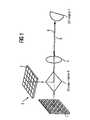
- FIG. 1shows an optical sensor, which records in three dimensions, with illumination and read out in a pixelwise fashion, it being possible to illuminate a three-dimensional object over its whole area;
- FIG. 2shows a system corresponding to FIG. 1 with a configuration of the arrangement of the light source and the receiving elements that is adapted to the measurement problem;
- FIG. 3shows a schematic arrangement of laser diodes relative to an optical system, and an arrangement of CMOS image converter elements
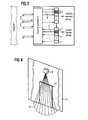
- FIG. 4shows a transmitting and receiving unit above a building entrance door for the purpose of safeguarding the building.
- the range-finding system proposed hereis based on the fact that consistent functional and spatial integration of microelectronics, photonics and optics has been undertaken in a microsystem with the exclusive use of solid state technology. Owing to the microelectronics, in particular the CMOS microelectronics, it is rendered possible to implement integrated, photosensitive arrangements with extremely short integration times, for example 50 ns, and thus to deduce indirectly, via the received intensity of laser pulses, the travel time of the latter, or the range of the object point from the measuring system. A reduction in the laser power required over all can be achieved by multiple repetition of pulsed exposure, integration and logic combination.
- the principleis based on the consideration that, in the case of the use of the random image access inherent in the CMOS technology, only that pixel is illuminated at a given time whose intensity is read out instantaneously at the corresponding receiving element. Consequently, the system simultaneously resolves pixels, and it is possible to dispense with mechanical scanning.
- the light powerthen distributed over several light sources or laser diodes, which are of substantially lower power and operating serially, drastically reduces the problems of rising times and power supply as well as costs and aspects of laser protection.
- the measurement uncertainties, achievable with the aid of the disclosed measuring system, of ⁇ 5 cm in a measuring range from 0.5 to 5 mare realistic.
- FIGS. 1 and 2show a spatially resolving range-finding system which includes on the left-hand side an arrangement with light sources 1 , emitted illuminating beams 5 being guided via a divider mirror 8 and an optical system 4 , and illuminating at least partially a three-dimensional object 7 .
- Imaging beams 6 reflected by the object 7are guided via the same optical system 4 and the divider mirror 8 onto a solid state image converter 3 , 31 , and evaluated by receiving elements 2 corresponding to the light sources 1 .
- the evaluationis performed optoelectronically, and yields a complete or partial contour image of the object 7 .
- the light sources 1 and the receiving elements 2 as a rectangular matrixis suitable for recording a complete three-dimensional image of an object 7 .
- the partial illumination described by means of serially actuating light sources 1leads overall to the complete recording of the object 7 .
- the serial response of the light sources 1 combined with the serial reading out of the corresponding receiving elements 2can be carried out at high speed.
- the abovementioned correspondencemeans that an illuminating beam 5 generated centrally in the arrangement of the light sources 1 passes, after reflection at the object 7 , via the divider mirror 8 into the centrally placed receiving element 2 of the solid state image converter 3 . This holds in a corresponding way for all the other light sources 1 and receiving elements 2 .
- FIG. 2shows an arrangement corresponding to FIG. 1, in which the light sources 1 and the solid state image converter 31 are designed in a fashion matched to the task.
- the designselected in the illustration, in the form of a cross, projects onto the object 7 merely a similar cross, which can be evaluated via the arrangement, likewise designed as a cross, of receiving elements 2 . It is possible in this way to detect substantial characteristic features of an object 7 , subsequent categorization being possible. This means that, in the case of a face, for example, specific contours are viewed without illuminating and evaluating the entire face.
- FIG. 3The mode of operation of the laser diode array as an illuminating unit, the optical system 4 and the CMOS sensor array at the receiving end is illustrated schematically in FIG. 3.
- the light source 11emphasized in the drawing, of the laser diode array emits an illuminating beam 5 which is guided to the object 7 via the optical system 4 .
- the reflected imaging beam 6is guided correspondingly via the optical system 4 onto a receiving element 21 , which corresponds to the above-named light source 11 and is likewise emphasized in the drawing of FIG. 3.
- the currently considered and/or active illuminating beams 5 and imaging beams 6are illustrated in FIG. 3 with continuous strokes. A corresponding statement holds for the beams illustrated by broken strokes, which are, however, present offset in time.
- Possible fields of application of spatially resolving range-finding systemsare speed measurement, vehicle identification, security surveillance, railroad platform surveillance, railroad grid crossing surveillance, material flow measurement on conveyor belts, or automation of crane systems by means of three-dimensional determination of position.
- FIG. 4The intelligent surveillance of a building entrance door is sketched in FIG. 4.
- the transmitting/receiving unit 9is fitted above a house door 10 of a house 11 .
- the points of impingement of the corresponding light beams on the groundare arranged in FIG. 4 in the form of a semicircle 12 . They therefore cover the area in front of the house door 10 .
- the range-finding systemin this case undertakes a partial illumination of an object appearing in front of the house door 10 , the contour of the object can be evaluated and categorized. This means, for example, that it is possible to establish whether a dog, a cat or a person is located in front of the door. There is no need in this case to illuminate the entire area of the object.
- each beam pathcan be guided specifically through an appropriately configured optical system.
Landscapes
- Engineering & Computer Science (AREA)
- Physics & Mathematics (AREA)
- Computer Networks & Wireless Communication (AREA)
- General Physics & Mathematics (AREA)
- Radar, Positioning & Navigation (AREA)
- Remote Sensing (AREA)
- Electromagnetism (AREA)
- Length Measuring Devices By Optical Means (AREA)
- Measurement Of Optical Distance (AREA)
- Optical Radar Systems And Details Thereof (AREA)
Abstract
Description
- The invention relates to a spatially resolving range-finding system for constructing three-dimensional objects. Such systems are preferably used to identify persons or objects for the purpose of access control or for general surveillance tasks. Sensor systems which record and process in three dimensions are becoming increasingly important for the most varied tasks in industrial technology. The conceivable applications are extremely manifold and comprehensive and must be supported by a new generation of optical sensors for industrial metrology.[0001]
- Known optical radar systems, such as laser radar, for example, are based either on the principle of laser pulse travel time measurement or on the determination of the phase indifference of modulated laser light for the purpose of deriving the object distance. Mechanical scanning devices are additionally required for the purpose of constructing a three-dimensional imaging system. This leads to a relatively expensive electronic and mechanical outlay which restricts the use of such three dimensional systems to a few special applications.[0002]
- Also known are methods in which depth photos are obtained (gated view) with the aid of short term laser illumination and electrooptic switches as well as with CCD cameras. Disadvantages of these sensors reside in a high laser power and in expensive electrooptic shutters. Since CCD cameras generally are operated only according to the television standard, only long read out times can be achieved.[0003]
- It is the object of the invention to provide, by avoiding the disadvantages of the prior art, a spatially resolving range-finding system with the aid of which it is possible to generate three-dimensional images rapidly and cost-effectively.[0004]
- This object is achieved by means of the combination of features corresponding to claim[0005]1.
- A substantial feature of the invention resides in executing the implementation of the range-finding system using only solid state technology. Furthermore, an single relatively strong light source is replaced by an arrangement, for example in the form of a matrix, of weaker light sources. The light power in relation to the previously high power of a single light source is reduced in relation to the whole-area illumination relative to the number of pixels. The range-finding system manages without moving parts. Limits of laser protection regulations can be observed straight away. Owing to the corresponding arrangement of light sources, on the one hand, and receiving elements of a solid state image converter, on the other hand, it is possible for the object points illuminated by a light source and thereby defined to be respectively received with accurate assignment by a receiving element of the solid state image converter and evaluated with regard to the range.[0006]
- The distribution of a relatively high light power over a multiplicity of light sources with a prescribed arrangement produces advantages such as a shorter rise time of the amplitude of the light, a higher accuracy of the measurement and ease of compliance with limits, for example from laser protection regulations.[0007]
- The range-finding system resolves pixels such that individual object points or their range or their contour value can be imaged in a differentiated fashion. This is achieved, in particular, by an advantageous configuration in which the system is provided with light sources which can be driven optionally and receiving elements which can be read out optionally. The correspondence between light sources and receiving elements can advantageously be varied in such a way that not only is there a 1:1 assignment, but, for example, one light source corresponds to several receiving elements combined to form one group. Equally, a group of light sources can serve a single receiving element.[0008]
- The result of a measurement consists in a generated three-dimensional image of an object, a contour image, or in the form of a sectional view which reproduces the external shape of the object at a specific section of the object with the aid of the illuminating beams.[0009]
- A whole-area illumination of an object is expediently performed with the aid of a whole-area arrangement with respectively dedicated light sources and receiving elements. It is advantageous for these arrangements respectively to be designed rectangularly in the form of a matrix. If there is no need for such a whole-area illumination or measurement of an object, the light sources and the receiving elements can be arranged in a fashion matched to the task. This means, for example, that, while retaining the correspondence between light sources and receiving elements, a specific line or surface is selected in each case as their arrangement, a corresponding line or surface on the object being detected. Designing this arrangement in a fashion matched to the task is taken to mean that the corresponding arrangements of the light source and the receiving elements are adapted to the shape of the object or to probable positions of the object.[0010]
- It is advantageous to use modulable laser diodes as light sources. The design of the solid state image converter in the form of an CMOS (metal oxide semiconductor) image converter is associated with a cost-effective design which permits individual receiving elements to be read out optionally in a rapid and reliable fashion.[0011]
- The use of a spatially resolving range-finding system according to the invention for the purpose of building entrance safeguarding is associated with particular advantages. An appropriate sensor operates with light and not with other, potentially damaging radiations. If laser diodes are used, their individual light power is so low that laser protection regulations are complied with straight away. The arrangement or configuration of the transmitting and receiving units of the measuring system can be adapted specifically to the object.[0012]
- Exemplary embodiments which do not limit the invention are described below with the aid of the accompanying schematics, in which:[0013]
- FIG. 1 shows an optical sensor, which records in three dimensions, with illumination and read out in a pixelwise fashion, it being possible to illuminate a three-dimensional object over its whole area;[0014]
- FIG. 2 shows a system corresponding to FIG. 1 with a configuration of the arrangement of the light source and the receiving elements that is adapted to the measurement problem;[0015]
- FIG. 3 shows a schematic arrangement of laser diodes relative to an optical system, and an arrangement of CMOS image converter elements; and[0016]
- FIG. 4 shows a transmitting and receiving unit above a building entrance door for the purpose of safeguarding the building.[0017]
- Taking and constructing three-dimensional images plays a substantial role chiefly for identification or for access control, that is to say for surveillance tasks in general. Thus, in future a key role will be ascribed to the rapid, cost-effective and robust acquisition of three-dimensional images in industrial sensor technology. An essential precondition for this is, above all, the implementation of this sensor technology with the exclusive use of solid state technology. The applications resulting therefrom are extremely manifold and comprehensive, and open up a new generation of optical sensors for industrial metrology. These three-dimensional microsystems are used, for example, in traffic surveillance and room surveillance as well as in the guidance of transportation operations. In addition to identifying objects, it is also possible to measure speeds. A flow of material can be monitored and automated.[0018]
- The range-finding system proposed here is based on the fact that consistent functional and spatial integration of microelectronics, photonics and optics has been undertaken in a microsystem with the exclusive use of solid state technology. Owing to the microelectronics, in particular the CMOS microelectronics, it is rendered possible to implement integrated, photosensitive arrangements with extremely short integration times, for example 50 ns, and thus to deduce indirectly, via the received intensity of laser pulses, the travel time of the latter, or the range of the object point from the measuring system. A reduction in the laser power required over all can be achieved by multiple repetition of pulsed exposure, integration and logic combination.[0019]
- A very decisive role is accorded photonics in this system. High demands must be placed on the laser light source with regard to rise time and constancy. The rise time should be less than 1 ns. A substantial reduction in this set of problems is achieved by the novel approach of synchronizing illumination of object sections and addressing corresponding regions from the sensor array. This is to be understood to include the corresponding configuration of the measuring system, the individual light sources, which assigns individual light sources which illuminate the object points provided to corresponding receiving elements.[0020]
- The principle is based on the consideration that, in the case of the use of the random image access inherent in the CMOS technology, only that pixel is illuminated at a given time whose intensity is read out instantaneously at the corresponding receiving element. Consequently, the system simultaneously resolves pixels, and it is possible to dispense with mechanical scanning. The light power then distributed over several light sources or laser diodes, which are of substantially lower power and operating serially, drastically reduces the problems of rising times and power supply as well as costs and aspects of laser protection. The measurement uncertainties, achievable with the aid of the disclosed measuring system, of ±5 cm in a measuring range from 0.5 to 5 m are realistic.[0021]
- In the case of the serial operation of individual laser diodes with the corresponding receiving elements, it is possible, in turn, to permit substantially higher luminance at the site of the object than in the case of a whole-area illumination without the laser protection regulations being infringed. This leads to a substantially improved signal-to-noise ratio at the receiving elements, and thus to a substantially increased efficiency of the overall system.[0022]
- FIGS. 1 and 2 show a spatially resolving range-finding system which includes on the left-hand side an arrangement with light sources[0023]1, emitted
illuminating beams 5 being guided via adivider mirror 8 and anoptical system 4, and illuminating at least partially a three-dimensional object 7.Imaging beams 6 reflected by theobject 7 are guided via the sameoptical system 4 and thedivider mirror 8 onto a solidstate image converter elements 2 corresponding to the light sources1. The evaluation is performed optoelectronically, and yields a complete or partial contour image of theobject 7. The form of the arrangements, illustrated in FIG. 1, of the light sources1 and the receivingelements 2 as a rectangular matrix is suitable for recording a complete three-dimensional image of anobject 7. The partial illumination described by means of serially actuating light sources1 leads overall to the complete recording of theobject 7. The serial response of the light sources1 combined with the serial reading out of thecorresponding receiving elements 2 can be carried out at high speed. As illustrated in FIG. 1, the abovementioned correspondence means that an illuminatingbeam 5 generated centrally in the arrangement of the light sources1 passes, after reflection at theobject 7, via thedivider mirror 8 into the centrally placed receivingelement 2 of the solidstate image converter 3. This holds in a corresponding way for all the other light sources1 and receivingelements 2. The use of a multiplicity of light sources1 with a corresponding number of receivingelements 2, combined with a serial illumination of theobject 7 does not give rise to any sorts of problems for the power supply of the light sources in order to comply with limits of a laser protection regulation or a requisite short rise time in the case of the modulation of the light sources1. This is to be viewed in contrast to the prior art, in which a single light source of high power is used. - FIG. 2 shows an arrangement corresponding to FIG. 1, in which the light sources[0024]1 and the solid
state image converter 31 are designed in a fashion matched to the task. The design, selected in the illustration, in the form of a cross, projects onto theobject 7 merely a similar cross, which can be evaluated via the arrangement, likewise designed as a cross, of receivingelements 2. It is possible in this way to detect substantial characteristic features of anobject 7, subsequent categorization being possible. This means that, in the case of a face, for example, specific contours are viewed without illuminating and evaluating the entire face. - The mode of operation of the laser diode array as an illuminating unit, the[0025]
optical system 4 and the CMOS sensor array at the receiving end is illustrated schematically in FIG. 3. Thelight source 11, emphasized in the drawing, of the laser diode array emits an illuminatingbeam 5 which is guided to theobject 7 via theoptical system 4. The reflectedimaging beam 6 is guided correspondingly via theoptical system 4 onto a receiving element21, which corresponds to the above-namedlight source 11 and is likewise emphasized in the drawing of FIG. 3. The currently considered and/or active illuminatingbeams 5 andimaging beams 6 are illustrated in FIG. 3 with continuous strokes. A corresponding statement holds for the beams illustrated by broken strokes, which are, however, present offset in time. - Possible fields of application of spatially resolving range-finding systems are speed measurement, vehicle identification, security surveillance, railroad platform surveillance, railroad grid crossing surveillance, material flow measurement on conveyor belts, or automation of crane systems by means of three-dimensional determination of position.[0026]
- The intelligent surveillance of a building entrance door is sketched in FIG. 4. The transmitting/receiving unit[0027]9 is fitted above a
house door 10 of ahouse 11. The points of impingement of the corresponding light beams on the ground are arranged in FIG. 4 in the form of asemicircle 12. They therefore cover the area in front of thehouse door 10. Since the range-finding system in this case undertakes a partial illumination of an object appearing in front of thehouse door 10, the contour of the object can be evaluated and categorized. This means, for example, that it is possible to establish whether a dog, a cat or a person is located in front of the door. There is no need in this case to illuminate the entire area of the object. Corresponding arrangements of the beam paths can be defined for the surveillance of objects of other types. In accordance with the configuration in FIG. 4, the arrangement of the light sources1 and the arrangement of the receivingelements 2 is likewise semicircular. In addition, each beam path can be guided specifically through an appropriately configured optical system.
Claims (15)
1. A spatially resolving range-finding system with the aid of which light travel time measurements can be carried out in a pixelwise fashion, comprising:
a one- or two-dimensional arrangement of modulable light sources;
a solid state image converter with receiving elements which exhibit a correspondence to the light sources with reference to the arrangement;
an optical system for guiding illuminating beams and imaging beams between light sources which can be driven serially, individually or in groups, object points corresponding thereto, and receiving elements driven correspondingly with the light sources it being possible to determine the range from each object point to the corresponding receiving element of the solid state image converter with the aid of a light travel time measurement.
2. The spatially resolving range-finding system according toclaim 1 , in which the correspondence between the arrangements of the light sources and the receiving elements is given by the use of a divider mirror and an optical system.
3. The spatially resolving range-finding system according toclaim 1 , in which, in the case of relatively large ranges between an object and the range-finding system, the arrangements of the light sources and the receiving elements are positioned immediately next to one another and their front is aligned in the direction of the object.
4. The spatially resolving range-finding system according toclaim 1 , in which the light sources can be driven optionally, and the corresponding receiving elements can be read out optionally.
5. The spatially resolving range-finding system according toclaim 1 , in which an optical system in the beam path of the illuminating beam and the imaging beam is designed in such a way that either one light source corresponds to one receiving element several light sources correspond to one receiving element or one light source corresponds to several receiving elements.
6. The spatially resolving range-finding system according toclaim 1 , in which the division is the same within the arrangements of the light sources and the receiving elements.
7. The spatially resolving range-finding system according toclaim 1 , in which the arrangement of the light sources and the arrangement of the receiving elements are represented in the form of a rectangular matrix in each case.
8. The spatially resolving range-finding system according toclaim 1 , in which the arrangement of the light sources and the arrangement of the receiving elements are designed in a fashion matched to the task.
9. The spatially resolving range-finding system according toclaim 8 , in which the arrangement of the light sources and the arrangement of the receiving elements are represented by a line, a full circle, a semicircle or cross.
10. The spatially resolving range-finding system according toclaim 1 , in which a sectional view or a three-dimensional image of an object is generated.
11. The spatially resolving range-finding system according toclaim 1 , in which the light sources are represented by rapidly modulable laser diodes or light-emitting diodes.
12. The spatially resolving range-finding system according toclaim 1 , in which the solid state image converter is represented by CMOS image converter.
13. The spatially resolving range-finding system according toclaim 1 , in which the light travel time measurement is a pulse travel time measurement or a phase measurement.
14. The spatially resolving range-finding system according toclaim 1 , for the purpose of intelligent building entrance safeguarding, railroad platform surveillance, railroad grid crossing surveillance or vehicle surveillance.
15. The spatially resolving range-finding system according toclaim 1 , for the purpose of surveillance of interiors of buildings or vehicles.
Applications Claiming Priority (4)
| Application Number | Priority Date | Filing Date | Title |
|---|---|---|---|
| DE19912196 | 1999-03-18 | ||
| DE19912196.6 | 1999-03-18 | ||
| DE19912196 | 1999-03-18 | ||
| PCT/DE2000/000814WO2000055642A1 (en) | 1999-03-18 | 2000-03-16 | Resoluting range finding device |
Related Parent Applications (1)
| Application Number | Title | Priority Date | Filing Date |
|---|---|---|---|
| PCT/DE2000/000814ContinuationWO2000055642A1 (en) | 1999-03-18 | 2000-03-16 | Resoluting range finding device |
Publications (2)
| Publication Number | Publication Date |
|---|---|
| US20020003617A1true US20020003617A1 (en) | 2002-01-10 |
| US6636300B2 US6636300B2 (en) | 2003-10-21 |
Family
ID=7901506
Family Applications (1)
| Application Number | Title | Priority Date | Filing Date |
|---|---|---|---|
| US09/944,496Expired - LifetimeUS6636300B2 (en) | 1999-03-18 | 2001-08-31 | Spatially resolving range-finding system |
Country Status (5)
| Country | Link |
|---|---|
| US (1) | US6636300B2 (en) |
| EP (1) | EP1159636B1 (en) |
| DE (1) | DE50002356D1 (en) |
| ES (1) | ES2199822T3 (en) |
| WO (1) | WO2000055642A1 (en) |
Cited By (32)
| Publication number | Priority date | Publication date | Assignee | Title |
|---|---|---|---|---|
| GB2374743A (en)* | 2001-04-04 | 2002-10-23 | Instro Prec Ltd | Surface profile measurement |
| US20050195383A1 (en)* | 1994-05-23 | 2005-09-08 | Breed David S. | Method for obtaining information about objects in a vehicular blind spot |
| US7248344B2 (en) | 2001-04-04 | 2007-07-24 | Instro Precision Limited | Surface profile measurement |
| US20070182528A1 (en)* | 2000-05-08 | 2007-08-09 | Automotive Technologies International, Inc. | Vehicular Component Control Methods Based on Blind Spot Monitoring |
| US20070181786A1 (en)* | 2004-09-28 | 2007-08-09 | Siemens Aktiengesellschaft | Device for monitoring spatial areas |
| US20080007710A1 (en)* | 2004-07-22 | 2008-01-10 | B.E.A. S.A. | Door sensor system for detecting a target object |
| WO2008009536A1 (en)* | 2006-07-17 | 2008-01-24 | Siemens Aktiengesellschaft | Industrial plant having safety-relevant area |
| EP2041515A4 (en)* | 2006-07-13 | 2009-11-11 | Velodyne Acoustics Inc | High definition lidar system |
| US20100302528A1 (en)* | 2009-06-02 | 2010-12-02 | Velodyne Acoustics, Inc. | Color lidar scanner |
| US20110216304A1 (en)* | 2006-07-13 | 2011-09-08 | Velodyne Acoustics, Inc. | High definition lidar system |
| US20130076861A1 (en)* | 2010-01-21 | 2013-03-28 | Shmuel Sternklar | Method and apparatus for probing an object, medium or optical path using noisy light |
| US20130314693A1 (en)* | 2012-05-23 | 2013-11-28 | Jds Uniphase Corporation | Range imaging devices and methods |
| CN104035097A (en)* | 2014-07-01 | 2014-09-10 | 清华大学 | No-scanning three-dimensional laser detection device received by array transmitting unit and method |
| JP2016534346A (en)* | 2013-08-20 | 2016-11-04 | グーグル インコーポレイテッド | Apparatus and method for rotating LIDAR platform with shared transmission / light receiving path |
| USRE46672E1 (en) | 2006-07-13 | 2018-01-16 | Velodyne Lidar, Inc. | High definition LiDAR system |
| WO2019002484A1 (en)* | 2017-06-29 | 2019-01-03 | Osram Opto Semiconductors Gmbh | OPTICAL SPACING MEASURING DEVICE AND METHOD FOR OPERATING AN OPTICAL SPACING MEASUREMENT DEVICE |
| US20190170866A1 (en)* | 2017-12-05 | 2019-06-06 | Sharp Kabushiki Kaisha | Photoreceptor, flight time measurement device, and optical radar |
| EP3540458A1 (en)* | 2018-03-12 | 2019-09-18 | OMRON Corporation | Optical safety sensor |
| US10983218B2 (en) | 2016-06-01 | 2021-04-20 | Velodyne Lidar Usa, Inc. | Multiple pixel scanning LIDAR |
| US11025885B2 (en) | 2015-09-24 | 2021-06-01 | Ouster, Inc. | Optical system for collecting distance information within a field |
| US11073617B2 (en) | 2016-03-19 | 2021-07-27 | Velodyne Lidar Usa, Inc. | Integrated illumination and detection for LIDAR based 3-D imaging |
| US11082010B2 (en) | 2018-11-06 | 2021-08-03 | Velodyne Lidar Usa, Inc. | Systems and methods for TIA base current detection and compensation |
| US11137480B2 (en) | 2016-01-31 | 2021-10-05 | Velodyne Lidar Usa, Inc. | Multiple pulse, LIDAR based 3-D imaging |
| US11294041B2 (en) | 2017-12-08 | 2022-04-05 | Velodyne Lidar Usa, Inc. | Systems and methods for improving detection of a return signal in a light ranging and detection system |
| US11614542B1 (en)* | 2017-08-11 | 2023-03-28 | Zoox, Inc. | Lidar photosensor amplification circuit |
| US11703569B2 (en) | 2017-05-08 | 2023-07-18 | Velodyne Lidar Usa, Inc. | LIDAR data acquisition and control |
| US11796648B2 (en) | 2018-09-18 | 2023-10-24 | Velodyne Lidar Usa, Inc. | Multi-channel lidar illumination driver |
| US11808891B2 (en) | 2017-03-31 | 2023-11-07 | Velodyne Lidar Usa, Inc. | Integrated LIDAR illumination power control |
| US11885958B2 (en) | 2019-01-07 | 2024-01-30 | Velodyne Lidar Usa, Inc. | Systems and methods for a dual axis resonant scanning mirror |
| US11906670B2 (en) | 2019-07-01 | 2024-02-20 | Velodyne Lidar Usa, Inc. | Interference mitigation for light detection and ranging |
| US11971507B2 (en) | 2018-08-24 | 2024-04-30 | Velodyne Lidar Usa, Inc. | Systems and methods for mitigating optical crosstalk in a light ranging and detection system |
| US12061263B2 (en) | 2019-01-07 | 2024-08-13 | Velodyne Lidar Usa, Inc. | Systems and methods for a configurable sensor system |
Families Citing this family (23)
| Publication number | Priority date | Publication date | Assignee | Title |
|---|---|---|---|---|
| US7783403B2 (en)* | 1994-05-23 | 2010-08-24 | Automotive Technologies International, Inc. | System and method for preventing vehicular accidents |
| US7630806B2 (en)* | 1994-05-23 | 2009-12-08 | Automotive Technologies International, Inc. | System and method for detecting and protecting pedestrians |
| US8041483B2 (en)* | 1994-05-23 | 2011-10-18 | Automotive Technologies International, Inc. | Exterior airbag deployment techniques |
| EP1380811B2 (en)* | 2002-07-03 | 2013-08-07 | Optosys SA | Optical distance measuring device |
| DE102004019337A1 (en) | 2004-04-21 | 2005-11-17 | Siemens Ag | Assistance system for motor vehicles |
| DE102005056265A1 (en) | 2005-11-14 | 2007-05-16 | Pilz Gmbh & Co Kg | Device and method for monitoring a room area, in particular for securing a danger zone of an automated system |
| US8822894B2 (en) | 2011-01-07 | 2014-09-02 | California Institute Of Technology | Light-field pixel for detecting a wavefront based on a first intensity normalized by a second intensity |
| DE102007023101A1 (en)* | 2007-05-16 | 2008-11-20 | Sick Ag | Optoelectronic sensor arrangement and method for monitoring a monitoring area |
| EP2026097A1 (en) | 2007-08-08 | 2009-02-18 | Harman Becker Automotive Systems GmbH | Vehicle illumination system |
| DE102008007451A1 (en)* | 2008-01-31 | 2009-08-06 | Carl Zeiss Microimaging Gmbh | Arrangement for three-dimensional mapping of scene, has receiving unit with two-dimensional detector surface for local resolution detection of light, which is reflected or controlled from objects located in different areas of scene |
| US9046680B2 (en)* | 2008-03-07 | 2015-06-02 | California Institute Of Technology | Scanning illumination microscope |
| WO2011035299A2 (en)* | 2009-09-21 | 2011-03-24 | California Institute Of Technology | Reflective focusing and transmissive projection device |
| WO2011047053A2 (en)* | 2009-10-13 | 2011-04-21 | California Institute Of Technology | Holographically illuminated imaging devices |
| WO2011106324A2 (en)* | 2010-02-23 | 2011-09-01 | California Institute Of Technology | Nondiffracting beam detection devices for three-dimensional imaging |
| WO2012033957A2 (en) | 2010-09-09 | 2012-03-15 | California Institute Of Technology | Delayed emission detection devices and methods |
| US9086536B2 (en) | 2011-03-09 | 2015-07-21 | California Institute Of Technology | Talbot imaging devices and systems |
| WO2012145566A2 (en) | 2011-04-20 | 2012-10-26 | California Institute Of Technology | Talbot-illuminated imaging devices, systems, and methods for focal plane tuning |
| US12123950B2 (en) | 2016-02-15 | 2024-10-22 | Red Creamery, LLC | Hybrid LADAR with co-planar scanning and imaging field-of-view |
| US12399279B1 (en) | 2016-02-15 | 2025-08-26 | Red Creamery Llc | Enhanced hybrid LIDAR with high-speed scanning |
| US11556000B1 (en) | 2019-08-22 | 2023-01-17 | Red Creamery Llc | Distally-actuated scanning mirror |
| US12399278B1 (en) | 2016-02-15 | 2025-08-26 | Red Creamery Llc | Hybrid LIDAR with optically enhanced scanned laser |
| DE102018222777A1 (en)* | 2018-12-21 | 2020-06-25 | Robert Bosch Gmbh | Optoelectronic sensor and method for operating an optoelectronic sensor |
| CN109782299B (en)* | 2019-02-14 | 2021-11-02 | 深圳市迈测科技股份有限公司 | Solid-state laser radar device |
Family Cites Families (11)
| Publication number | Priority date | Publication date | Assignee | Title |
|---|---|---|---|---|
| DE2802477C3 (en)* | 1978-01-20 | 1981-08-20 | Precitronic Gesellschaft für Feinmechanik und Electronik mbH, 2000 Hamburg | Device for sending and / or receiving laser light with several laser light emitting and / or detecting optronic elements |
| DE2818942C2 (en)* | 1978-04-28 | 1986-03-27 | Zellweger Uster Ag, Uster | Method for room monitoring and device for carrying out the method |
| DE3915627A1 (en) | 1989-05-12 | 1990-11-15 | Dornier Luftfahrt | OPTICAL RADAR |
| DE3942770A1 (en) | 1989-12-23 | 1991-07-11 | Dornier Luftfahrt | DISTANCE IMAGE CAMERA |
| EP0464263A3 (en)* | 1990-06-27 | 1992-06-10 | Siemens Aktiengesellschaft | Device for obstacle detection for pilots of low flying aircrafts |
| US5047776A (en)* | 1990-06-27 | 1991-09-10 | Hughes Aircraft Company | Multibeam optical and electromagnetic hemispherical/spherical sensor |
| DE4440613C1 (en)* | 1994-11-14 | 1996-07-25 | Leica Ag | Device and method for the detection and demodulation of an intensity-modulated radiation field |
| US5784023A (en)* | 1995-06-26 | 1998-07-21 | Bluege; John | Speed detection method |
| DE19616038A1 (en)* | 1996-04-23 | 1997-10-30 | Bosch Gmbh Robert | Method and measuring device for determining the position of an object |
| US5953110A (en)* | 1998-04-23 | 1999-09-14 | H.N. Burns Engineering Corporation | Multichannel laser radar |
| US6207967B1 (en)* | 1999-03-04 | 2001-03-27 | Valeo Electrical Systems, Inc. | Off the glass imaging rain sensor |
- 2000
- 2000-03-16DEDE50002356Tpatent/DE50002356D1/ennot_activeExpired - Lifetime
- 2000-03-16ESES00925048Tpatent/ES2199822T3/ennot_activeExpired - Lifetime
- 2000-03-16WOPCT/DE2000/000814patent/WO2000055642A1/enactiveIP Right Grant
- 2000-03-16EPEP00925048Apatent/EP1159636B1/ennot_activeExpired - Lifetime
- 2001
- 2001-08-31USUS09/944,496patent/US6636300B2/ennot_activeExpired - Lifetime
Cited By (73)
| Publication number | Priority date | Publication date | Assignee | Title |
|---|---|---|---|---|
| US20050195383A1 (en)* | 1994-05-23 | 2005-09-08 | Breed David S. | Method for obtaining information about objects in a vehicular blind spot |
| US7209221B2 (en)* | 1994-05-23 | 2007-04-24 | Automotive Technologies International, Inc. | Method for obtaining and displaying information about objects in a vehicular blind spot |
| US20070182528A1 (en)* | 2000-05-08 | 2007-08-09 | Automotive Technologies International, Inc. | Vehicular Component Control Methods Based on Blind Spot Monitoring |
| US7852462B2 (en) | 2000-05-08 | 2010-12-14 | Automotive Technologies International, Inc. | Vehicular component control methods based on blind spot monitoring |
| US7248344B2 (en) | 2001-04-04 | 2007-07-24 | Instro Precision Limited | Surface profile measurement |
| GB2374743A (en)* | 2001-04-04 | 2002-10-23 | Instro Prec Ltd | Surface profile measurement |
| US20080007710A1 (en)* | 2004-07-22 | 2008-01-10 | B.E.A. S.A. | Door sensor system for detecting a target object |
| US7446862B2 (en)* | 2004-07-22 | 2008-11-04 | B.E.A.S.A. | Door sensor system for detecting a target object |
| US7701557B2 (en)* | 2004-09-28 | 2010-04-20 | Siemens Aktiengesellschaft | Device for monitoring spatial areas |
| US20070181786A1 (en)* | 2004-09-28 | 2007-08-09 | Siemens Aktiengesellschaft | Device for monitoring spatial areas |
| US8767190B2 (en) | 2006-07-13 | 2014-07-01 | Velodyne Acoustics, Inc. | High definition LiDAR system |
| USRE48688E1 (en) | 2006-07-13 | 2021-08-17 | Velodyne Lidar Usa, Inc. | High definition LiDAR system |
| USRE46672E1 (en) | 2006-07-13 | 2018-01-16 | Velodyne Lidar, Inc. | High definition LiDAR system |
| USRE48490E1 (en) | 2006-07-13 | 2021-03-30 | Velodyne Lidar Usa, Inc. | High definition LiDAR system |
| EP2041515A4 (en)* | 2006-07-13 | 2009-11-11 | Velodyne Acoustics Inc | High definition lidar system |
| US7969558B2 (en) | 2006-07-13 | 2011-06-28 | Velodyne Acoustics Inc. | High definition lidar system |
| US20110216304A1 (en)* | 2006-07-13 | 2011-09-08 | Velodyne Acoustics, Inc. | High definition lidar system |
| USRE48491E1 (en) | 2006-07-13 | 2021-03-30 | Velodyne Lidar Usa, Inc. | High definition lidar system |
| USRE48504E1 (en) | 2006-07-13 | 2021-04-06 | Velodyne Lidar Usa, Inc. | High definition LiDAR system |
| US20100020306A1 (en)* | 2006-07-13 | 2010-01-28 | Velodyne Acoustics, Inc. | High definition lidar system |
| USRE48503E1 (en) | 2006-07-13 | 2021-04-06 | Velodyne Lidar Usa, Inc. | High definition LiDAR system |
| USRE47942E1 (en) | 2006-07-13 | 2020-04-14 | Velodyne Lindar, Inc. | High definition lidar system |
| USRE48666E1 (en) | 2006-07-13 | 2021-08-03 | Velodyne Lidar Usa, Inc. | High definition LiDAR system |
| WO2008009536A1 (en)* | 2006-07-17 | 2008-01-24 | Siemens Aktiengesellschaft | Industrial plant having safety-relevant area |
| RU2439163C2 (en)* | 2006-07-17 | 2012-01-10 | Сименс Акциенгезелльшафт | Production plant with zone relating to safety control |
| US20090315229A1 (en)* | 2006-07-17 | 2009-12-24 | Siemens Aktiengesellschaft | Industrial plant having safety-relevant area |
| US8675181B2 (en) | 2009-06-02 | 2014-03-18 | Velodyne Acoustics, Inc. | Color LiDAR scanner |
| US20100302528A1 (en)* | 2009-06-02 | 2010-12-02 | Velodyne Acoustics, Inc. | Color lidar scanner |
| US20130076861A1 (en)* | 2010-01-21 | 2013-03-28 | Shmuel Sternklar | Method and apparatus for probing an object, medium or optical path using noisy light |
| US20130314693A1 (en)* | 2012-05-23 | 2013-11-28 | Jds Uniphase Corporation | Range imaging devices and methods |
| US9046359B2 (en)* | 2012-05-23 | 2015-06-02 | Jds Uniphase Corporation | Range imaging devices and methods |
| US9397470B2 (en) | 2012-05-23 | 2016-07-19 | Lumentum Operations Llc | Range imaging devices and methods |
| JP2016534346A (en)* | 2013-08-20 | 2016-11-04 | グーグル インコーポレイテッド | Apparatus and method for rotating LIDAR platform with shared transmission / light receiving path |
| CN104035097B (en)* | 2014-07-01 | 2016-09-28 | 清华大学 | The no-raster three-dimensional laser detection device and method that a kind of array emitter unit receives |
| CN104035097A (en)* | 2014-07-01 | 2014-09-10 | 清华大学 | No-scanning three-dimensional laser detection device received by array transmitting unit and method |
| US11202056B2 (en) | 2015-09-24 | 2021-12-14 | Ouster, Inc. | Optical system with multiple light emitters sharing a field of view of a pixel detector |
| US11627298B2 (en) | 2015-09-24 | 2023-04-11 | Ouster, Inc. | Optical system for collecting distance information within a field |
| US11025885B2 (en) | 2015-09-24 | 2021-06-01 | Ouster, Inc. | Optical system for collecting distance information within a field |
| US11196979B2 (en) | 2015-09-24 | 2021-12-07 | Ouster, Inc. | Optical system for collecting distance information within a field |
| US11956410B2 (en) | 2015-09-24 | 2024-04-09 | Ouster, Inc. | Optical system for collecting distance information within a field |
| US12200183B2 (en) | 2015-09-24 | 2025-01-14 | Ouster, Inc. | Optical system for collecting distance information within a field |
| US11178381B2 (en) | 2015-09-24 | 2021-11-16 | Ouster, Inc. | Optical system for collecting distance information within a field |
| US11190750B2 (en) | 2015-09-24 | 2021-11-30 | Ouster, Inc. | Optical imaging system with a plurality of sense channels |
| US11698443B2 (en) | 2016-01-31 | 2023-07-11 | Velodyne Lidar Usa, Inc. | Multiple pulse, lidar based 3-D imaging |
| US11822012B2 (en) | 2016-01-31 | 2023-11-21 | Velodyne Lidar Usa, Inc. | Multiple pulse, LIDAR based 3-D imaging |
| US11550036B2 (en) | 2016-01-31 | 2023-01-10 | Velodyne Lidar Usa, Inc. | Multiple pulse, LIDAR based 3-D imaging |
| US11137480B2 (en) | 2016-01-31 | 2021-10-05 | Velodyne Lidar Usa, Inc. | Multiple pulse, LIDAR based 3-D imaging |
| US11073617B2 (en) | 2016-03-19 | 2021-07-27 | Velodyne Lidar Usa, Inc. | Integrated illumination and detection for LIDAR based 3-D imaging |
| US11874377B2 (en) | 2016-06-01 | 2024-01-16 | Velodyne Lidar Usa, Inc. | Multiple pixel scanning LIDAR |
| US11550056B2 (en) | 2016-06-01 | 2023-01-10 | Velodyne Lidar Usa, Inc. | Multiple pixel scanning lidar |
| US11561305B2 (en) | 2016-06-01 | 2023-01-24 | Velodyne Lidar Usa, Inc. | Multiple pixel scanning LIDAR |
| US11808854B2 (en) | 2016-06-01 | 2023-11-07 | Velodyne Lidar Usa, Inc. | Multiple pixel scanning LIDAR |
| US10983218B2 (en) | 2016-06-01 | 2021-04-20 | Velodyne Lidar Usa, Inc. | Multiple pixel scanning LIDAR |
| US11808891B2 (en) | 2017-03-31 | 2023-11-07 | Velodyne Lidar Usa, Inc. | Integrated LIDAR illumination power control |
| US11703569B2 (en) | 2017-05-08 | 2023-07-18 | Velodyne Lidar Usa, Inc. | LIDAR data acquisition and control |
| WO2019002484A1 (en)* | 2017-06-29 | 2019-01-03 | Osram Opto Semiconductors Gmbh | OPTICAL SPACING MEASURING DEVICE AND METHOD FOR OPERATING AN OPTICAL SPACING MEASUREMENT DEVICE |
| US11644538B2 (en) | 2017-06-29 | 2023-05-09 | Osram Oled Gmbh | Optical distance measuring apparatus and method for operating an optical distance measuring apparatus |
| US11614542B1 (en)* | 2017-08-11 | 2023-03-28 | Zoox, Inc. | Lidar photosensor amplification circuit |
| US11726192B2 (en)* | 2017-12-05 | 2023-08-15 | Sharp Kabushiki Kaisha | Photoreceptor, flight time measurement device, and optical radar |
| US20190170866A1 (en)* | 2017-12-05 | 2019-06-06 | Sharp Kabushiki Kaisha | Photoreceptor, flight time measurement device, and optical radar |
| US20230052333A1 (en)* | 2017-12-08 | 2023-02-16 | Velodyne Lidar Usa, Inc. | Systems and methods for improving detection of a return signal in a light ranging and detection system |
| US11294041B2 (en) | 2017-12-08 | 2022-04-05 | Velodyne Lidar Usa, Inc. | Systems and methods for improving detection of a return signal in a light ranging and detection system |
| US11885916B2 (en)* | 2017-12-08 | 2024-01-30 | Velodyne Lidar Usa, Inc. | Systems and methods for improving detection of a return signal in a light ranging and detection system |
| TWI696843B (en)* | 2018-03-12 | 2020-06-21 | 日商歐姆龍股份有限公司 | Optical safety sensor |
| US11543488B2 (en) | 2018-03-12 | 2023-01-03 | Omron Corporation | Optical safety sensor |
| CN110261863A (en)* | 2018-03-12 | 2019-09-20 | 欧姆龙株式会社 | Optical profile type safety sensor |
| EP3540458A1 (en)* | 2018-03-12 | 2019-09-18 | OMRON Corporation | Optical safety sensor |
| US11971507B2 (en) | 2018-08-24 | 2024-04-30 | Velodyne Lidar Usa, Inc. | Systems and methods for mitigating optical crosstalk in a light ranging and detection system |
| US11796648B2 (en) | 2018-09-18 | 2023-10-24 | Velodyne Lidar Usa, Inc. | Multi-channel lidar illumination driver |
| US11082010B2 (en) | 2018-11-06 | 2021-08-03 | Velodyne Lidar Usa, Inc. | Systems and methods for TIA base current detection and compensation |
| US11885958B2 (en) | 2019-01-07 | 2024-01-30 | Velodyne Lidar Usa, Inc. | Systems and methods for a dual axis resonant scanning mirror |
| US12061263B2 (en) | 2019-01-07 | 2024-08-13 | Velodyne Lidar Usa, Inc. | Systems and methods for a configurable sensor system |
| US11906670B2 (en) | 2019-07-01 | 2024-02-20 | Velodyne Lidar Usa, Inc. | Interference mitigation for light detection and ranging |
Also Published As
| Publication number | Publication date |
|---|---|
| ES2199822T3 (en) | 2004-03-01 |
| US6636300B2 (en) | 2003-10-21 |
| EP1159636A1 (en) | 2001-12-05 |
| WO2000055642A1 (en) | 2000-09-21 |
| DE50002356D1 (en) | 2003-07-03 |
| EP1159636B1 (en) | 2003-05-28 |
Similar Documents
| Publication | Publication Date | Title |
|---|---|---|
| US6636300B2 (en) | Spatially resolving range-finding system | |
| US12078756B2 (en) | Methods and apparatus for array based lidar systems with reduced interference | |
| US20220137189A1 (en) | Method and device for optically measuring distances | |
| US6373557B1 (en) | Method and apparatus for picking up a three-dimensional range image | |
| US9621876B2 (en) | Scanning 3D imager | |
| CA3017819C (en) | Lidar based 3-d imaging with varying illumination intensity | |
| CN109557522A (en) | Multi-beam laser scanner | |
| US4070584A (en) | Object-identification system with sequentially activated photocell array | |
| JP4350385B2 (en) | Method for automatically searching for target marks, device for automatically searching for target marks, receiving unit, geodometer and geodetic system | |
| JP4405155B2 (en) | Image analysis system | |
| CN105473393B (en) | The sensor mechanism of posture is manipulated on vehicle for detecting | |
| US7202898B1 (en) | Self gating photosurface | |
| US7995836B2 (en) | Optoelectronic multiplane sensor and method for monitoring objects | |
| CN100432905C (en) | Method and device for optical navigation | |
| CN101641573B (en) | Optical sensor chip and anti-pinch device with such sensor chip | |
| JPH10508736A (en) | Apparatus and method for detecting and demodulating intensity-modulated fields | |
| JP7558371B2 (en) | Retroreflector detection and avoidance in LIDAR devices | |
| Mengel et al. | Fast range imaging by CMOS sensor array through multiple double short time integration (MDSI) | |
| US5082365A (en) | Remote identification and speed determination system | |
| CN100517198C (en) | pointing device | |
| EP4382960A1 (en) | Guided flash lidar | |
| CN114144693A (en) | Conditioning equipment and lidar measurement equipment | |
| Hussmann et al. | A review on commercial solid state 3D cameras for machine vision applications | |
| JP7176364B2 (en) | DISTANCE INFORMATION ACQUISITION DEVICE AND DISTANCE INFORMATION ACQUISITION METHOD | |
| JP4560912B2 (en) | Distance measuring device |
Legal Events
| Date | Code | Title | Description |
|---|---|---|---|
| AS | Assignment | Owner name:SIEMENS AKTIENGESELLSCHAFT, GERMANY Free format text:ASSIGNMENT OF ASSIGNORS INTEREST;ASSIGNORS:DOEMENS, GUENTER;MENGEL, PETER;REEL/FRAME:012508/0215;SIGNING DATES FROM 20010718 TO 20010719 | |
| STCF | Information on status: patent grant | Free format text:PATENTED CASE | |
| FPAY | Fee payment | Year of fee payment:4 | |
| FPAY | Fee payment | Year of fee payment:8 | |
| FPAY | Fee payment | Year of fee payment:12 |