US20010048396A1 - Scanning, circularly polarized varied impedance transmission line antenna - Google Patents
Scanning, circularly polarized varied impedance transmission line antennaDownload PDFInfo
- Publication number
- US20010048396A1 US20010048396A1US09/871,139US87113901AUS2001048396A1US 20010048396 A1US20010048396 A1US 20010048396A1US 87113901 AUS87113901 AUS 87113901AUS 2001048396 A1US2001048396 A1US 2001048396A1
- Authority
- US
- United States
- Prior art keywords
- line
- transmission line
- varied
- ground plane
- meander
- Prior art date
- Legal status (The legal status is an assumption and is not a legal conclusion. Google has not performed a legal analysis and makes no representation as to the accuracy of the status listed.)
- Granted
Links
- 230000005540biological transmissionEffects0.000titleclaimsabstractdescription57
- 230000010287polarizationEffects0.000claimsabstractdescription15
- 239000003989dielectric materialSubstances0.000claimsdescription7
- 230000009977dual effectEffects0.000claimsdescription6
- 230000005684electric fieldEffects0.000claimsdescription3
- 239000000463materialSubstances0.000claimsdescription3
- 238000003491arrayMethods0.000abstractdescription14
- 230000008859changeEffects0.000description5
- 239000004020conductorSubstances0.000description5
- 238000004519manufacturing processMethods0.000description5
- 230000000694effectsEffects0.000description3
- 230000033001locomotionEffects0.000description3
- 230000004048modificationEffects0.000description3
- 238000012986modificationMethods0.000description3
- 230000005404monopoleEffects0.000description3
- 230000008901benefitEffects0.000description2
- 238000010276constructionMethods0.000description2
- 238000010586diagramMethods0.000description2
- 238000000034methodMethods0.000description2
- 230000010363phase shiftEffects0.000description2
- 230000004044responseEffects0.000description2
- RYGMFSIKBFXOCR-UHFFFAOYSA-NCopperChemical compound[Cu]RYGMFSIKBFXOCR-UHFFFAOYSA-N0.000description1
- 230000015572biosynthetic processEffects0.000description1
- 229910052802copperInorganic materials0.000description1
- 239000010949copperSubstances0.000description1
- 230000008878couplingEffects0.000description1
- 238000010168coupling processMethods0.000description1
- 238000005859coupling reactionMethods0.000description1
- 238000006880cross-coupling reactionMethods0.000description1
- 230000007423decreaseEffects0.000description1
- 230000001419dependent effectEffects0.000description1
- 230000003993interactionEffects0.000description1
- 230000005855radiationEffects0.000description1
- 230000009467reductionEffects0.000description1
- 230000003068static effectEffects0.000description1
- 239000000758substrateSubstances0.000description1
- 229910000859α-FeInorganic materials0.000description1
Images


Classifications
- H—ELECTRICITY
- H01—ELECTRIC ELEMENTS
- H01Q—ANTENNAS, i.e. RADIO AERIALS
- H01Q1/00—Details of, or arrangements associated with, antennas
- H01Q1/36—Structural form of radiating elements, e.g. cone, spiral, umbrella; Particular materials used therewith
- H—ELECTRICITY
- H01—ELECTRIC ELEMENTS
- H01Q—ANTENNAS, i.e. RADIO AERIALS
- H01Q13/00—Waveguide horns or mouths; Slot antennas; Leaky-waveguide antennas; Equivalent structures causing radiation along the transmission path of a guided wave
- H01Q13/20—Non-resonant leaky-waveguide or transmission-line antennas; Equivalent structures causing radiation along the transmission path of a guided wave
- H—ELECTRICITY
- H01—ELECTRIC ELEMENTS
- H01Q—ANTENNAS, i.e. RADIO AERIALS
- H01Q9/00—Electrically-short antennas having dimensions not more than twice the operating wavelength and consisting of conductive active radiating elements
- H01Q9/04—Resonant antennas
- H01Q9/30—Resonant antennas with feed to end of elongated active element, e.g. unipole
- H01Q9/32—Vertical arrangement of element
- H—ELECTRICITY
- H01—ELECTRIC ELEMENTS
- H01Q—ANTENNAS, i.e. RADIO AERIALS
- H01Q9/00—Electrically-short antennas having dimensions not more than twice the operating wavelength and consisting of conductive active radiating elements
- H01Q9/04—Resonant antennas
- H01Q9/30—Resonant antennas with feed to end of elongated active element, e.g. unipole
- H01Q9/42—Resonant antennas with feed to end of elongated active element, e.g. unipole with folded element, the folded parts being spaced apart a small fraction of the operating wavelength
Definitions
- the inventionpertains to meander line loaded antenna and, more particularly, to multi-element antennas and arrays of such antennas, and more specifically to a scanning phased array MLA with circular polarization.
- MLAmeander line loaded antenna
- Meander linesare designed to adjust the electrical length of the antenna.
- the design of the meander slow wave structurepermits lengths of the meander line to be switched in or out of the circuit quickly with negligible loss. This is done in order to change the effective electrical length of the antenna. This switching is possible because the active switching devices are always located in the high impedance sections of the meander line. This keeps the current through the switching devices low resulting in very low dissipation losses in the switch, and high antenna efficiency.
- the simple, basic MLAcan be operated in a loop mode that provides a “figure eight” coverage pattern.
- Horizontal polarization loop modemay be obtained when the antenna is operated at a frequency wherein the electrical length of the entire line, including the meander lines is a multiple of full wavelength.
- the antennacan also be operated in a vertically polarized monopole mode, by adjusting the electrical length to an odd multiple of a half wavelength at operating frequency.
- the meander linescan be tuned using electrical or mechanical switches to change the mode of operation at a given frequency, or to switch the frequency in a given mode.
- the MLAallows the physical dimensions of antennas to be significantly reduced, while maintaining an electrical length that is still a multiple and radiating structures of a quarter wavelength.
- Meander line loaded antennasachieve the efficiency limit of the Chu-Harrington relationship although the antenna size is much less than a wavelength at the frequency of operation. Height reductions of 10 to 1 can be achieved with comparable gain over quarter wave monopole antennas.
- the existing MLA antennasare narrow band antennas. Although the switchable meander line allows the antennas to cover wider frequency bands, the instantaneous bandwidth is narrow.
- array antennasare very expensive because each antenna receives its own, separate signal. These signals, typically, are generated by using an external corporate feed network. These limitations are further magnified in the case of phased array antennas that achieve directional control by varying the phase of the transmission signal between different array elements, thus requiring phase control for each element.
- the aforementioned U.S. Pat. No. 5,790,080describes an antenna that includes one or more conductive elements that act as radiating antenna elements and a slow wave meander line that couples electrical signals between the conductive elements.
- the meander linehas an effective electrical length that affects the electrical length and operating characteristics of the antenna. The electrical length and operating mode of the antenna is readily controlled.
- U.S. Pat. No. 5,943,011 entitled ANTENNA ARRAY USING SIMPLIFIED BEAM FORMING NETWORKdiscloses an example of an antenna array, or multi-element antenna and the feed network used for steering signals transmitted or received through the array.
- the signals coupled to and from each antenna elementare adjusted in phase by a network of radio frequency (RF) hybrid devices.
- RFradio frequency
- U.S. Pat. No. 5,144,319 entitled PLANAR SUBSTRATE FERRITE/DIODE PHASE SHIFTER FOR PHASED ARRAY APPLICATIONSis an example of a phase shifter that can be used for an individual antenna element within an array, and shows the use of this shifter for each antenna element of a phased array.
- U.S. Pat. No. 4,010,474 entitled TWO DIMENSIONAL ARRAY ANTENNAdiscloses a phase control network for the elements of a two dimensional array.
- U.S. Pat. No. 5,949,303 entitled MOVABLE DIELECTRIC BODY FOR CONTROLLING PROPAGATION VELOCITY IN A FEED LINEdiscloses a single phase shifter for use with multiple array elements.
- a feed conductor lineincludes a source input and multiple antenna element outputs.
- a moveable dielectric materiallocated between the feed line, or the carrier plate thereof, and a ground plane, controls the propagation velocity of signals coupled through the feed line. In this manner a mechanical adjustment is made which determines the phasing of multiple antenna elements.
- a maneuverable, scanning, phased-array, meander line loaded antennahaving circular polarization.
- Linear arrays or transmission lines of crossed MLA elementseach allow the application of two feeds—a first signal feed and a 90° phase shifted signal feed.
- each linear arraytherefore, can radiate a circularly polarized RF signal.
- a compact, low-cost, scanning phased arraymay be built by forming a symmetrical superstructure of these linear arrays.
- the inventive antenna structuremay be readily formed using printed circuit manufacturing techniques.
- An array antennafor an inexpensive, dual-feed, array antenna utilizing a stepped or varied impedance transmission line to provide an active antenna array.
- the stepped nature of the antenna elementscreate a varied impedance transmission line as those sections that are further from the ground plane have a greater impedance than those elements closer to the ground plane.
- the higher impedance sectionsfunction as individual active array elements for radiating or receiving. Variation of the spacing among the active elements controls the antenna gain pattern. And, the delay line characteristics of the meander line elements are used to control the phase relationship of the antenna elements.
- the present inventionsimplifies the design and manufacture of a phased-array MLA having circular polarization.
- the inventive antennahas an easily controlled beam and pointing direction.
- the inventionalso reduces the complexity of phased-array control logic and reduces the fabrication cost for phased-array antennas, especially antennas where circular polarization is required.
- the inventionfeatures an array of orthogonal meander lines, and a movable back plate. This creates a slow wave configuration, which provides the necessary phase shift, producing a circular, polarized, radiation pattern.
- One of the features of the inventionis the formation of linear arrays of multiple crossed MLA elements that may then be arranged into a symmetrical array.
- a movable ground planeprovides for frequency tuning of the elements.
- the symmetrical array so formedprovides a scanning, maneuverable phased array.
- the structure of the crossed MLA elements as a plurality of interconnected transmission linesprovides operation in a circularly polarized array.
- An object of the inventionis a varied impedance transmission line antenna, comprising a ground plane with a transmission line disposed substantially parallel to and in close proximity to the ground plane, wherein the transmission line is a plurality of crossed meander line loaded elements each having an upper element and a lower element.
- a first conducting lineis interconnecting the upper element of each of the crossed meander line loaded elements and a second conducting line is interconnecting the lower element of each of the crossed meander line loaded elements.
- the crossed meander line loaded elementsare connected in series by the first and second conducting line and form an alternating impedance pattern based upon a spacing from the ground plane, wherein the first and second conducting line is a low impedance section and the crossed meander line loaded elements are a high impedance section.
- a further objectis the varied impedance transmission line antenna, wherein the first conducting line is connected to a first signal feed and the second conducting line is connected to a second signal feed. And, also where the first and second signal feed are phase-shifted by 90 degrees to place the feeds in quadrature.
- a propagation constantis varied by changing the spacing.
- the spacingcan be varied dynamically, substantially continuously, and periodically by moving the ground plane.
- the ground planecan be mechanically moved by means a stepper motor or a piezoelectric actuator.
- a dielectric materialcan be disposed between the plurality of crossed meander line loaded elements and the ground plane with an adjustable dielectric constant, such as ferroelectric material, and the dielectric constant is changeable by an applied electric field.
- An object of the inventionis a varied impedance transmission line antenna, comprising a ground plane with a transmission line disposed substantially parallel to and in close proximity to the ground plane, wherein the transmission line is a plurality of dual bow-tie meander line loaded elements with a first bow-tie element disposed orthogonal to a second bow-tie element.
- An aspect of the inventionis includes where the bow-tie meander line loaded elements are connected in series by the first and second conducting line and form an alternating impedance pattern based upon a spacing from the ground plane.
- the first and second conducting lineis a low impedance section and the bow-tie meander line loaded elements are a high impedance section.
- a further aspect of the inventionis that the ground plane is moveable.
- an additional objectis the varied impedance transmission line antenna, wherein the first conducting line is connected to a first signal feed and the second conducting line is connected to a second signal feed.
- An object of the inventionis a varied impedance transmission line antenna array, comprising a ground plane with two or more transmission lines disposed substantially parallel to and in close proximity to the ground plane, wherein the transmission lines are a plurality of crossed meander line loaded elements each having a first element and a second element. There is a first conducting line interconnecting the first element of each of the crossed meander line loaded elements and a second conducting line interconnecting the second element of each of the crossed meander line loaded elements. In this configuration it is easy to form a two-dimensional array. And the first and second signal feed can be selectively applied to the plurality of crossed meander line loaded elements, whereby the antenna is steerable. Furthermore, the first and second signal feed can be selectively applied to the plurality of crossed meander line loaded elements, whereby an operating frequency of the phased-array antenna is scannable.
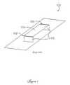
- FIG. 1is a schematic, perspective view of a meander line loaded loop antenna of the prior art
- FIG. 2is a schematic, perspective view of a meander line used as an element coupler in the meander line loaded loop antenna of FIG. 1;
- FIG. 3consisting of a series of diagrams 3 a - 3 d depicts four operating modes of the antenna of FIG. 1;
- FIG. 4is a schematic, cross-sectional view of a typical meander line having a movable ground plane
- FIG. 5is a schematic, perspective view of the single crossed MLA element
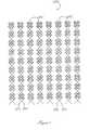
- FIG. 6is a schematic view of a linear array of the crossed MLA elements of FIG. 5;
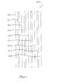
- FIG. 7is a schematic view of a two-dimensional array of the linear arrays of FIG. 6;
- FIG. 8is a schematic, cross-sectional view of a printed circuit implementation of the inventive antenna.
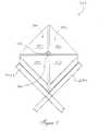
- FIG. 9is a schematic, perspective view of a pair of orthogonal bow-tic meander antenna elements.
- FIG. 1illustrates the prior art meander line loaded structure 100 described in more detail is U.S. Pat. No. 5,790,080.
- a pair of opposing side units 102are connected to a ground plane 105 and extend substantially orthogonal from the ground plane 105 .
- a horizontal top cover 104extends between the side pieces 102 , but does not come in direct contact with the side units 102 . Instead, there are gaps 106 separating the side pieces 102 from the top cover 104 .
- a meander line loaded element 108such as the one depicted in FIG. 2 is placed on the inner sides 102 or inner surface of the top cover 104 of the structure 100 such that the meander line 108 resides in the gaps 106 .
- FIG. 3there are shown four typical operating modalities for the MLA 100 shown in FIG. 1 in combination with the meander line 108 a (FIG. 2). Quarter wavelength 1 ⁇ 2, 1 and ⁇ fraction (3/2) ⁇ modes of operation are shown.
- the meander line loaded structure 108provides a switching means to change the electrical length of the line and thereby effect the properties of the structure 100 . As explained in more detail in the prior art, the switching enables the structure to operate in loop mode or monopole mode by altering the electrical length and hence the wavelengths as shown in FIGS. 3 A-D.
- the meander line 200is a slow wave structure.
- the propagation constant in the structurecan be controlled and is given by:
- the propagation velocityis thus dependent upon the ratio of alternating impedance values of the varied transmission line.
- impedance valuesThere are many factors that contribute to the impedance values, including the size of the transmission lines, the dielectric constant of the dielectric, and the spacing between the transmission line and the ground plane.
- the remaining adjustable variableis the spacing, which is used to effect the propagation constant.
- One of the unique aspects of this inventionis the nature of the stepped or varied impedance transmission line and the interaction with the moveable ground plane.
- the alternating spacing of the transmission line from the ground planecreates alternating impedance. Varying the spacing enables control of the antenna gain pattern. And, the delay line characteristics of the transmission line effect the phase relationship that is used to further influence and control the antenna.
- the propagation constantIn order to achieve an array that can be pointed and scanned, the propagation constant must be varied with time. This is achieved by changing the distance d 202 between a ground plane 204 and low impedance sections 206 of the meander line 208 . Thus, the delay between the high Z radiating sections is adjusted by changing the spacing d 202 between the low Z sections 206 and the ground plane. The low Z sections are more dramatically affected by the movement of the ground plane as opposed to the high Z sections.
- the mechanical motion of ground plane 204can be accomplished by using stepper motors or piezoelectric motors (not shown) to drive a mechanical linkage to the ground plane.
- the space 202 between the ground plane 204 and the low impedance sections 206 of the meander line 208can contain a ferroelectric material 210 with a dielectric constant that can be varied by applying an electric field (not shown). Both the implementation of the mechanical moving means and altering the dielectric constant are known to those skilled in the art.
- Each MLA element 212 a , 212 bis a high impedance section 212 of meander line 208 (FIG. 4), and they have traditional loop construction.
- Upper crossed element 212 aconsists of two vertical radiating surfaces 122 separated from a horizontal surface 224 b by gaps (not shown).
- Lower crossed element 212 bconsists of two vertical radiating surfaces 222 separated from a horizontal surface 224 a by gaps (not shown).
- These antenna elementsrepresent the high impedance portion of two distinct meander lines. This configuration, when properly fed in quadrature as is known in the art, is capable of producing a circularly polarized signal.
- Each MLA element 212 a , 212 bis connected to a low-impedance section 206 a , 206 b corresponding to low-impedance section 206 of meander line 208 (FIG. 4). These low impedance portions of the meander lines 206 a , 206 b connect to the next element in the linear array. The overlapping low impedance portions 206 a and 206 b are not electrically connected at the junction point, thus isolating the two signal feeds as they traverse the transmission line.
- Multiple linear arraysmay be interconnected and arranged to form a square or rectangle as shown herein, as well as other shapes in conformance with the principles of the present invention.
- This configurationwhen properly fed, is capable of producing a circularly polarized signal for the array structure.
- the low impedance sectionsare striplines, such as copper, that interconnects the sequential orthogonal antenna sections
- FIG. 6there is shown a schematic top view diagram of a linear array 240 formed from a series of MLA crossed elements 220 (FIG. 5) also called cells forming the transmission line 240 .
- the multiple orthogonal meander line antennas 220are interconnected to and by the low impedance lines 206 a , 206 b .
- linear array 240By properly feeding linear array 240 with an RF signal 242 and 90° phase-shifted RF signal 244 , circular polarization of a radiated signal is maintained.
- Two-dimensional array 260allows the antenna to be steered through selective energization of selective linear arrays 240 .
- the antenna formed by two-dimensional array 260is tuned.
- the frequency response of antenna 260may be swept (i.e., scanned).
- Ground plane 204has a dielectric layer 210 on its upper surface.
- a low-impedance portion 212 b of the lower level meander lineis then formed on top of dielectric material 210 .
- a second dielectric layer 302is formed over low-impedance portion 212 b .
- the low-impedance portion 212 a or the upper meander lineis formed over dielectric material 302 .
- a first via layer 304which allows electrical connection to internal planes of the antenna 300 , is formed atop and insulated from low impedance portion 212 a .
- the lower element radiating surface 224 bis formed over first via layer 304 .
- the upper element radiating surface 224 ais formed over radiating surface 224 b .
- the functionality of the printed circuitis the same as described herein.
- FIG. 9Another embodiment of incorporates a bow-tie arrangement as shown in FIG. 9.
- Pending U.S. Patent Application entitled NARROW-BAND, SYMMETRIC, CROSSED, CIRCULARLY POLARIZED MEANDER LINE LOADED ANTENNAthat is herein incorporated by reference.
- FIG. 9there is shown a schematic, perspective view of an improved, crossed-element MLA, a bow-tie structure 400 .
- This structureis called a crossed MLA in that it operates as a crossed element antenna.
- the pair of MLA orthogonal crossed MLA elements 220(FIG. 5) are replaced by pairs of triangular elements 410 , 420 , 430 , and 440 .
- Elements 410 and 430are electrically coupled at point 450 , and their interior vertices form a first bow-tie element 126 .
- elements 420 and 440are coupled at point 470 to form a second bow-tie element 480 , orthogonal to first bow-tie element 460 .
- Bow-tie elements 460 , 480are each meander line loaded elements. Whereas the orthogonal crossed antenna 220 (FIG. 5), has antenna element crossing over each other there is some cross-coupling, which is reduced by the bow-tie elements 460 , 480 . In addition, the axial response from the inventive arrangement is improved. To achieve circular polarization, the bow-tie elements 460 , 480 are fed in quadrature (i.e., the feeds are 90° out-of-phase) as is well known to those skilled in the antenna design arts. The bow-tie elements represent the high impedance sections.
- Each MLA element 460 , 480is connected to a low-impedance section 206 a , 206 b corresponding to low-impedance section 206 of meander line 208 (FIG. 4), and the entire structure is disposed above a ground plane (not shown).
- These low impedance portions of the meander lines 206 a , 206 bconnect to the next bow-tie element in a linear array.
- Multiple linear arraysmay be arranged to form a square or rectangle as shown herein, as well as other shapes in conformance with the principles of the present invention. The other aspects of the invention recited herein are applicable to the bow-tie arrangement.
Landscapes
- Variable-Direction Aerials And Aerial Arrays (AREA)
Abstract
Description
- Applicant hereby claims the priority benefits in accordance with the provisions of 35 U.S.C. §119, basing said claim on United States Provisional Patent Application Serial No. 60/208,192, filed May 31, 2000. Pending patent application Ser. No. 09/844135 entitled SINGLE FEED, MULTI-ELEMENT ANTENNA filed Apr. 27, 2001 and pending US Patent Application entitled NARROW-BAND, SYMMETRIC, CROSSED, CIRCULARLY POLARIZED MEANDER LINE LOADED ANTENNA filed May 31, 2001 are incorporated by reference herein.[0001]
- The invention pertains to meander line loaded antenna and, more particularly, to multi-element antennas and arrays of such antennas, and more specifically to a scanning phased array MLA with circular polarization.[0002]
- In the past, efficient antennas have typically required structures with minimum dimensions on the order of a quarter wavelength of the radiating frequency. These dimensions allow the antenna to be easily excited, and to operate at or near resonance. This limits the energy dissipated in resistive losses, and maximizes the transmitted energy. This type of antenna tends to be large in size at the resonant wavelength. Further, as frequency decreases, antenna dimensions increase in proportion.[0003]
- In order to address the shortcomings of traditional antenna design and functionality, the meander line loaded antenna (MLA) was developed. One such antenna is disclosed in U.S. Pat. No. 5,790,080, entitled MEANDER LINE LOADED ANTENNA hereby incorporated by reference. One type of MLA described in this prior art patent was for two spaced-apart vertical conductors attached to a ground plane, and a horizontal conductor located across the top of the vertical conductors. The vertical and horizontal conductors are separated by gaps, one or both of which are bridged by meander lines.[0004]
- Meander lines are designed to adjust the electrical length of the antenna. In addition, the design of the meander slow wave structure permits lengths of the meander line to be switched in or out of the circuit quickly with negligible loss. This is done in order to change the effective electrical length of the antenna. This switching is possible because the active switching devices are always located in the high impedance sections of the meander line. This keeps the current through the switching devices low resulting in very low dissipation losses in the switch, and high antenna efficiency.[0005]
- The simple, basic MLA can be operated in a loop mode that provides a “figure eight” coverage pattern. Horizontal polarization loop mode, may be obtained when the antenna is operated at a frequency wherein the electrical length of the entire line, including the meander lines is a multiple of full wavelength. The antenna can also be operated in a vertically polarized monopole mode, by adjusting the electrical length to an odd multiple of a half wavelength at operating frequency. The meander lines can be tuned using electrical or mechanical switches to change the mode of operation at a given frequency, or to switch the frequency in a given mode.[0006]
- The MLA allows the physical dimensions of antennas to be significantly reduced, while maintaining an electrical length that is still a multiple and radiating structures of a quarter wavelength. Meander line loaded antennas achieve the efficiency limit of the Chu-Harrington relationship although the antenna size is much less than a wavelength at the frequency of operation. Height reductions of 10 to 1 can be achieved with comparable gain over quarter wave monopole antennas. The existing MLA antennas are narrow band antennas. Although the switchable meander line allows the antennas to cover wider frequency bands, the instantaneous bandwidth is narrow.[0007]
- The meander line loaded antenna, as well as antennas in general, have certain limitations when used in arrays. Currently, array antennas are very expensive because each antenna receives its own, separate signal. These signals, typically, are generated by using an external corporate feed network. These limitations are further magnified in the case of phased array antennas that achieve directional control by varying the phase of the transmission signal between different array elements, thus requiring phase control for each element.[0008]
- The aforementioned U.S. Pat. No. 5,790,080 describes an antenna that includes one or more conductive elements that act as radiating antenna elements and a slow wave meander line that couples electrical signals between the conductive elements. The meander line has an effective electrical length that affects the electrical length and operating characteristics of the antenna. The electrical length and operating mode of the antenna is readily controlled.[0009]
- U.S. Pat. No. 5,943,011 entitled ANTENNA ARRAY USING SIMPLIFIED BEAM FORMING NETWORK discloses an example of an antenna array, or multi-element antenna and the feed network used for steering signals transmitted or received through the array. The signals coupled to and from each antenna element are adjusted in phase by a network of radio frequency (RF) hybrid devices.[0010]
- U.S. Pat. No. 5,144,319 entitled PLANAR SUBSTRATE FERRITE/DIODE PHASE SHIFTER FOR PHASED ARRAY APPLICATIONS is an example of a phase shifter that can be used for an individual antenna element within an array, and shows the use of this shifter for each antenna element of a phased array.[0011]
- U.S. Pat. No. 4,010,474 entitled TWO DIMENSIONAL ARRAY ANTENNA discloses a phase control network for the elements of a two dimensional array.[0012]
- U.S. Pat. No. 5,949,303 entitled MOVABLE DIELECTRIC BODY FOR CONTROLLING PROPAGATION VELOCITY IN A FEED LINE discloses a single phase shifter for use with multiple array elements. As shown in FIG. 1, a feed conductor line includes a source input and multiple antenna element outputs. A moveable dielectric material located between the feed line, or the carrier plate thereof, and a ground plane, controls the propagation velocity of signals coupled through the feed line. In this manner a mechanical adjustment is made which determines the phasing of multiple antenna elements.[0013]
- The prior art shows the level of complexity that is required for the use of multiple element antenna arrays. There are a number of difficulties relating to individual connections as well as problems relating to phase control. What is needed is a simplified coupling and phase control that enables multi-element antennas that are simple to manufacture and operate without sacrificing performance.[0014]
- In accordance with the present invention there is provided a maneuverable, scanning, phased-array, meander line loaded antenna having circular polarization. Linear arrays or transmission lines of crossed MLA elements each allow the application of two feeds—a first signal feed and a 90° phase shifted signal feed. When properly connected, each linear array, therefore, can radiate a circularly polarized RF signal. A compact, low-cost, scanning phased array may be built by forming a symmetrical superstructure of these linear arrays. For high-frequency applications, the inventive antenna structure may be readily formed using printed circuit manufacturing techniques.[0015]
- An array antenna is disclosed for an inexpensive, dual-feed, array antenna utilizing a stepped or varied impedance transmission line to provide an active antenna array. The stepped nature of the antenna elements create a varied impedance transmission line as those sections that are further from the ground plane have a greater impedance than those elements closer to the ground plane. The higher impedance sections function as individual active array elements for radiating or receiving. Variation of the spacing among the active elements controls the antenna gain pattern. And, the delay line characteristics of the meander line elements are used to control the phase relationship of the antenna elements.[0016]
- The present invention simplifies the design and manufacture of a phased-array MLA having circular polarization. The inventive antenna has an easily controlled beam and pointing direction. The invention also reduces the complexity of phased-array control logic and reduces the fabrication cost for phased-array antennas, especially antennas where circular polarization is required.[0017]
- One of the structural differences between the antenna of the present invention and that of the related art, is that the invention features an array of orthogonal meander lines, and a movable back plate. This creates a slow wave configuration, which provides the necessary phase shift, producing a circular, polarized, radiation pattern.[0018]
- It is, therefore, an object of the invention to provide a crossed-element meander line loaded linear array having circular polarization capability. A further object is a bow-tie meander line loaded linear array having circular polarization.[0019]
- It is another object of the invention to provide a scanning, phase-structured MLA operating in a circular polarization mode, and formed from linear arrays of orthogonal MLA elements.[0020]
- One of the features of the invention is the formation of linear arrays of multiple crossed MLA elements that may then be arranged into a symmetrical array. A movable ground plane provides for frequency tuning of the elements. The symmetrical array so formed provides a scanning, maneuverable phased array. The structure of the crossed MLA elements as a plurality of interconnected transmission lines provides operation in a circularly polarized array.[0021]
- It is a further object of the invention to provide a scanning, phase-structured MLA with a movable back plate that operates in a circular polarization mode.[0022]
- It is an additional object of the invention to provide a scanning, phase-structured MLA operating in a circular polarization mode, and which is fabricated using printed circuit manufacturing techniques.[0023]
- An object of the invention is a varied impedance transmission line antenna, comprising a ground plane with a transmission line disposed substantially parallel to and in close proximity to the ground plane, wherein the transmission line is a plurality of crossed meander line loaded elements each having an upper element and a lower element. A first conducting line is interconnecting the upper element of each of the crossed meander line loaded elements and a second conducting line is interconnecting the lower element of each of the crossed meander line loaded elements.[0024]
- And, the crossed meander line loaded elements are connected in series by the first and second conducting line and form an alternating impedance pattern based upon a spacing from the ground plane, wherein the first and second conducting line is a low impedance section and the crossed meander line loaded elements are a high impedance section.[0025]
- A further object is the varied impedance transmission line antenna, wherein the first conducting line is connected to a first signal feed and the second conducting line is connected to a second signal feed. And, also where the first and second signal feed are phase-shifted by 90 degrees to place the feeds in quadrature.[0026]
- And yet another object is the varied impedance transmission line antenna, wherein a propagation constant is varied by changing the spacing. The spacing can be varied dynamically, substantially continuously, and periodically by moving the ground plane. The ground plane can be mechanically moved by means a stepper motor or a piezoelectric actuator. In addition, a dielectric material can be disposed between the plurality of crossed meander line loaded elements and the ground plane with an adjustable dielectric constant, such as ferroelectric material, and the dielectric constant is changeable by an applied electric field.[0027]
- An object of the invention is a varied impedance transmission line antenna, comprising a ground plane with a transmission line disposed substantially parallel to and in close proximity to the ground plane, wherein the transmission line is a plurality of dual bow-tie meander line loaded elements with a first bow-tie element disposed orthogonal to a second bow-tie element. There is a first conducting line interconnecting the first bow-tie element of each of the dual bow-tie meander line loaded elements and a second conducting line interconnecting the second bow-tie element of each of the dual bow-tie meander line loaded elements. An aspect of the invention is includes where the bow-tie meander line loaded elements are connected in series by the first and second conducting line and form an alternating impedance pattern based upon a spacing from the ground plane. The first and second conducting line is a low impedance section and the bow-tie meander line loaded elements are a high impedance section. A further aspect of the invention is that the ground plane is moveable.[0028]
- And, an additional object is the varied impedance transmission line antenna, wherein the first conducting line is connected to a first signal feed and the second conducting line is connected to a second signal feed.[0029]
- An object of the invention is a varied impedance transmission line antenna array, comprising a ground plane with two or more transmission lines disposed substantially parallel to and in close proximity to the ground plane, wherein the transmission lines are a plurality of crossed meander line loaded elements each having a first element and a second element. There is a first conducting line interconnecting the first element of each of the crossed meander line loaded elements and a second conducting line interconnecting the second element of each of the crossed meander line loaded elements. In this configuration it is easy to form a two-dimensional array. And the first and second signal feed can be selectively applied to the plurality of crossed meander line loaded elements, whereby the antenna is steerable. Furthermore, the first and second signal feed can be selectively applied to the plurality of crossed meander line loaded elements, whereby an operating frequency of the phased-array antenna is scannable.[0030]
- Still other objects and advantages of the present invention will become readily apparent to those skilled in this art from the following detailed description, wherein I have shown and described only a preferred embodiment of the invention, simply by way of illustration of the best mode contemplated by me on carrying out my invention. As will be realized, the invention is capable of other and different embodiments, and its several details are capable of modifications in various obvious respects, all without departing from the invention.[0031]
- A complete understanding of the present invention may be obtained by reference to the accompanying drawings, when considered in conjunction with the subsequent detailed description, in which:[0032]
- FIG. 1 is a schematic, perspective view of a meander line loaded loop antenna of the prior art;[0033]
- FIG. 2 is a schematic, perspective view of a meander line used as an element coupler in the meander line loaded loop antenna of FIG. 1;[0034]
- FIG. 3, consisting of a series of diagrams[0035]3a-3ddepicts four operating modes of the antenna of FIG. 1;
- FIG. 4 is a schematic, cross-sectional view of a typical meander line having a movable ground plane;[0036]
- FIG. 5 is a schematic, perspective view of the single crossed MLA element;[0037]
- FIG. 6 is a schematic view of a linear array of the crossed MLA elements of FIG. 5;[0038]
- FIG. 7 is a schematic view of a two-dimensional array of the linear arrays of FIG. 6;[0039]
- FIG. 8 is a schematic, cross-sectional view of a printed circuit implementation of the inventive antenna; and[0040]
- FIG. 9 is a schematic, perspective view of a pair of orthogonal bow-tic meander antenna elements.[0041]
- FIG. 1 illustrates the prior art meander line loaded[0042]
structure 100 described in more detail is U.S. Pat. No. 5,790,080. A pair of opposingside units 102 are connected to a ground plane105 and extend substantially orthogonal from the ground plane105. A horizontaltop cover 104 extends between theside pieces 102, but does not come in direct contact with theside units 102. Instead, there aregaps 106 separating theside pieces 102 from thetop cover 104. A meander line loadedelement 108, such as the one depicted in FIG. 2 is placed on theinner sides 102 or inner surface of thetop cover 104 of thestructure 100 such that themeander line 108 resides in thegaps 106. - Referring now to FIG. 3, there are shown four typical operating modalities for the[0043]
MLA 100 shown in FIG. 1 in combination with themeander line 108a(FIG. 2). Quarter wavelength ½, 1 and {fraction (3/2)} modes of operation are shown. The meander line loadedstructure 108 provides a switching means to change the electrical length of the line and thereby effect the properties of thestructure 100. As explained in more detail in the prior art, the switching enables the structure to operate in loop mode or monopole mode by altering the electrical length and hence the wavelengths as shown in FIGS.3A-D. - Referring now to FIG. 4, there is shown a schematic, cross-sectional view of the meander line generally at[0044]
reference number 200. Themeander line 200 is a slow wave structure. By designing the transmission line to have regions at different impedance levels the propagation constant in the structure can be controlled and is given by: - β=0/2(I1/I2½
- where:[0045]
- β[0046]0=2 π/λ0
- Z[0047]1=high impedance
- Z[0048]2=low impedance
- The propagation velocity is thus dependent upon the ratio of alternating impedance values of the varied transmission line. There are many factors that contribute to the impedance values, including the size of the transmission lines, the dielectric constant of the dielectric, and the spacing between the transmission line and the ground plane. However once the other variables are static, the remaining adjustable variable is the spacing, which is used to effect the propagation constant. By controlling the propagation constant, the phase of the signal at each radiating element in a linear array can be controlled. This allows the construction of a low cost phased array with a fixed pointing direction.[0049]
- One of the unique aspects of this invention is the nature of the stepped or varied impedance transmission line and the interaction with the moveable ground plane. The alternating spacing of the transmission line from the ground plane creates alternating impedance. Varying the spacing enables control of the antenna gain pattern. And, the delay line characteristics of the transmission line effect the phase relationship that is used to further influence and control the antenna.[0050]
- In order to achieve an array that can be pointed and scanned, the propagation constant must be varied with time. This is achieved by changing the[0051]
distance d 202 between aground plane 204 andlow impedance sections 206 of themeander line 208. Thus, the delay between the high Z radiating sections is adjusted by changing thespacing d 202 between thelow Z sections 206 and the ground plane. The low Z sections are more dramatically affected by the movement of the ground plane as opposed to the high Z sections. - The mechanical motion of[0052]
ground plane 204 can be accomplished by using stepper motors or piezoelectric motors (not shown) to drive a mechanical linkage to the ground plane. Alternatively, thespace 202 between theground plane 204 and thelow impedance sections 206 of themeander line 208 can contain aferroelectric material 210 with a dielectric constant that can be varied by applying an electric field (not shown). Both the implementation of the mechanical moving means and altering the dielectric constant are known to those skilled in the art. - Either of these actions (i.e., changing the distance between[0053]
ground plane 204 andlow impedance sections 202 of20meander line 206, and/or changing the dielectric constant ofdielectric material 210 within the region betweenground plane 204 andlow impedance sections 206 of line208) results in a change in the ratio of the high to the low impedance values. This change in impedance values in turn, changes the propagation constant and the phase shift experienced at each of the elements (i.e., high impedance sections212). - Aspects of the present invention are also described in pending patent application Ser. No. 09/844135 entitled SINGLE FEED, MULTI-ELEMENT ANTENNA. This invention utilizes crossed MLA antennas to form a transmission line having circular polarization and uses a compressed pattern with two signal feeds.[0054]
- Referring now to FIG. 5, there is shown a schematic, perspective view of a crossed MLA element, generally at[0055]
reference number 220. EachMLA element high impedance section 212 of meander line208 (FIG. 4), and they have traditional loop construction. Upper crossedelement 212aconsists of two vertical radiating surfaces122 separated from ahorizontal surface 224b by gaps (not shown). Lower crossedelement 212bconsists of two vertical radiating surfaces222 separated from ahorizontal surface 224aby gaps (not shown). These antenna elements represent the high impedance portion of two distinct meander lines. This configuration, when properly fed in quadrature as is known in the art, is capable of producing a circularly polarized signal. - Each[0056]
MLA element impedance section impedance section 206 of meander line208 (FIG. 4). These low impedance portions of themeander lines low impedance portions - Multiple linear arrays may be interconnected and arranged to form a square or rectangle as shown herein, as well as other shapes in conformance with the principles of the present invention. This configuration, when properly fed, is capable of producing a circularly polarized signal for the array structure. In one embodiment the low impedance sections are striplines, such as copper, that interconnects the sequential orthogonal antenna sections[0057]
- Referring now to FIG. 6, there is shown a schematic top view diagram of a[0058]
linear array 240 formed from a series of MLA crossed elements220 (FIG. 5) also called cells forming thetransmission line 240. As illustrated, the multiple orthogonalmeander line antennas 220 are interconnected to and by thelow impedance lines linear array 240 with anRF signal 242 and 90° phase-shiftedRF signal 244, circular polarization of a radiated signal is maintained. - Referring now also to FIG. 7, there is shown a schematic representation of a two-[0059]
dimensional array 260 formed fromlinear arrays 240. Two-dimensional array 260 allows the antenna to be steered through selective energization of selectivelinear arrays 240. - By moving the back plate (i.e., the ground plane)[0060]204 relative to meander line208 (FIG. 4) the antenna formed by two-
dimensional array 260 is tuned. By varyingspacing d 202 periodically or continuously, the frequency response ofantenna 260 may be swept (i.e., scanned). Combining thisback plate 204 movement with the selective energization oflinear arrays 240, a true scanning, steerable phased-array antenna is formed. - Referring now to FIG. 8, there is shown a schematic, cross-sectional view of a printed circuit implementation of the antenna of the present invention, generally at[0061]
reference number 300.Ground plane 204 has adielectric layer 210 on its upper surface. A low-impedance portion 212bof the lower level meander line is then formed on top ofdielectric material 210. Asecond dielectric layer 302 is formed over low-impedance portion 212b. The low-impedance portion 212aor the upper meander line is formed overdielectric material 302. A first vialayer 304, which allows electrical connection to internal planes of theantenna 300, is formed atop and insulated fromlow impedance portion 212a. The lowerelement radiating surface 224bis formed over first vialayer 304. Finally, the upperelement radiating surface 224ais formed over radiatingsurface 224b. The functionality of the printed circuit is the same as described herein. - Another embodiment of incorporates a bow-tie arrangement as shown in FIG. 9. Pending U.S. Patent Application entitled NARROW-BAND, SYMMETRIC, CROSSED, CIRCULARLY POLARIZED MEANDER LINE LOADED ANTENNA that is herein incorporated by reference.[0062]
- Referring now to FIG. 9, there is shown a schematic, perspective view of an improved, crossed-element MLA, a bow-[0063]
tie structure 400. This structure is called a crossed MLA in that it operates as a crossed element antenna. The pair of MLA orthogonal crossed MLA elements220 (FIG. 5) are replaced by pairs oftriangular elements Elements point 450, and their interior vertices form a first bow-tie element126. Likewise,elements point 470 to form a second bow-tie element 480, orthogonal to first bow-tie element 460. Bow-tie elements tie elements tie elements - Each[0064]
MLA element impedance section impedance section 206 of meander line208 (FIG. 4), and the entire structure is disposed above a ground plane (not shown). These low impedance portions of themeander lines - Since other modifications and changes varied to fit particular operating conditions and environments or designs will be apparent to those skilled in the art, the invention is not considered limited to the examples chosen for purposes of disclosure, and covers changes and modifications which do not constitute departures from the true scope of this invention. Having thus described the invention, what is desired to be protected by letters patents is presented in the subsequently appended[0065]
Claims (20)
Priority Applications (1)
| Application Number | Priority Date | Filing Date | Title |
|---|---|---|---|
| US09/871,139US6359599B2 (en) | 2000-05-31 | 2001-05-31 | Scanning, circularly polarized varied impedance transmission line antenna |
Applications Claiming Priority (2)
| Application Number | Priority Date | Filing Date | Title |
|---|---|---|---|
| US20819200P | 2000-05-31 | 2000-05-31 | |
| US09/871,139US6359599B2 (en) | 2000-05-31 | 2001-05-31 | Scanning, circularly polarized varied impedance transmission line antenna |
Publications (2)
| Publication Number | Publication Date |
|---|---|
| US20010048396A1true US20010048396A1 (en) | 2001-12-06 |
| US6359599B2 US6359599B2 (en) | 2002-03-19 |
Family
ID=22773589
Family Applications (1)
| Application Number | Title | Priority Date | Filing Date |
|---|---|---|---|
| US09/871,139Expired - LifetimeUS6359599B2 (en) | 2000-05-31 | 2001-05-31 | Scanning, circularly polarized varied impedance transmission line antenna |
Country Status (3)
| Country | Link |
|---|---|
| US (1) | US6359599B2 (en) |
| AU (1) | AU2001275024A1 (en) |
| WO (1) | WO2001093371A1 (en) |
Cited By (4)
| Publication number | Priority date | Publication date | Assignee | Title |
|---|---|---|---|---|
| US6630909B2 (en)* | 2001-08-01 | 2003-10-07 | Raymond R. Nepveu | Meander line loaded antenna and method for tuning |
| EP2673838A1 (en)* | 2011-02-11 | 2013-12-18 | Ami Research&development, LLC | High performance low profile antennas |
| US9246230B2 (en) | 2011-02-11 | 2016-01-26 | AMI Research & Development, LLC | High performance low profile antennas |
| US9806425B2 (en) | 2011-02-11 | 2017-10-31 | AMI Research & Development, LLC | High performance low profile antennas |
Families Citing this family (19)
| Publication number | Priority date | Publication date | Assignee | Title |
|---|---|---|---|---|
| US6597321B2 (en)* | 2001-11-08 | 2003-07-22 | Skycross, Inc. | Adaptive variable impedance transmission line loaded antenna |
| US7053832B2 (en)* | 2002-07-03 | 2006-05-30 | Lucent Technologies Inc. | Multiband antenna arrangement |
| US6888510B2 (en)* | 2002-08-19 | 2005-05-03 | Skycross, Inc. | Compact, low profile, circular polarization cubic antenna |
| US6950066B2 (en)* | 2002-08-22 | 2005-09-27 | Skycross, Inc. | Apparatus and method for forming a monolithic surface-mountable antenna |
| US7683841B2 (en)* | 2006-07-11 | 2010-03-23 | Samsung Electronics Co., Ltd. | Antenna device |
| GB0802729D0 (en)* | 2008-02-14 | 2008-03-26 | Isis Innovation | Resonant reflector assembly and method |
| US8502744B2 (en)* | 2008-09-16 | 2013-08-06 | Honeywell International Inc. | Scanning antenna |
| US8816925B2 (en) | 2009-05-06 | 2014-08-26 | Bae Systems Information And Electronic Systems Integration Inc. | Multiband whip antenna |
| US8081130B2 (en)* | 2009-05-06 | 2011-12-20 | Bae Systems Information And Electronic Systems Integration Inc. | Broadband whip antenna |
| US8665174B2 (en) | 2011-01-13 | 2014-03-04 | The Boeing Company | Triangular phased array antenna subarray |
| US8643554B1 (en) | 2011-05-25 | 2014-02-04 | The Boeing Company | Ultra wide band antenna element |
| US9099777B1 (en) | 2011-05-25 | 2015-08-04 | The Boeing Company | Ultra wide band antenna element |
| US9368879B1 (en) | 2011-05-25 | 2016-06-14 | The Boeing Company | Ultra wide band antenna element |
| US9147936B1 (en) | 2011-06-28 | 2015-09-29 | AMI Research & Development, LLC | Low-profile, very wide bandwidth aircraft communications antennas using advanced ground-plane techniques |
| US9166301B2 (en) | 2012-02-13 | 2015-10-20 | AMI Research & Development, LLC | Travelling wave antenna feed structures |
| US9172147B1 (en) | 2013-02-20 | 2015-10-27 | The Boeing Company | Ultra wide band antenna element |
| US9481332B1 (en) | 2013-06-14 | 2016-11-01 | The Boeing Company | Plug-n-play power system for an accessory in an aircraft |
| US9391375B1 (en) | 2013-09-27 | 2016-07-12 | The United States Of America As Represented By The Secretary Of The Navy | Wideband planar reconfigurable polarization antenna array |
| US9705199B2 (en) | 2014-05-02 | 2017-07-11 | AMI Research & Development, LLC | Quasi TEM dielectric travelling wave scanning array |
Family Cites Families (27)
| Publication number | Priority date | Publication date | Assignee | Title |
|---|---|---|---|---|
| US3633207A (en)* | 1969-01-21 | 1972-01-04 | Univ Illinois Foundation Urban | Modulated impedance feeding system for log-periodic antennas |
| US3736534A (en) | 1971-10-13 | 1973-05-29 | Litton Systems Inc | Planar-shielded meander slow-wave structure |
| US3754197A (en) | 1972-05-18 | 1973-08-21 | Sanford Research Inst | Meander-line impedance transformer |
| US3754271A (en) | 1972-07-03 | 1973-08-21 | Gte Sylvania Inc | Broadband antenna polarizer |
| US3849745A (en) | 1973-01-26 | 1974-11-19 | Westinghouse Electric Corp | Method and system for varying the characteristics of a dispersive delay line |
| US4010474A (en) | 1975-05-05 | 1977-03-01 | The United States Of America As Represented By The Secretary Of The Navy | Two dimensional array antenna |
| US4293858A (en) | 1979-11-23 | 1981-10-06 | International Telephone And Telegraph Corporation | Polarization agile meander line array |
| US4786914A (en) | 1985-01-25 | 1988-11-22 | E-Systems, Inc. | Meanderline polarization twister |
| FR2584872B1 (en) | 1985-07-09 | 1987-11-20 | Europ Agence Spatiale | BROADBAND FLAT ANTENNA WITH CIRCULAR POLARIZATION, USES OF SUCH ANTENNA, APPLICATIONS, AND MANUFACTURING METHOD |
| US5144319A (en) | 1991-03-14 | 1992-09-01 | Electromagnetic Sciences, Inc. | Planar substrate ferrite/diode phase shifter for phased array applications |
| JP3324243B2 (en) | 1993-03-30 | 2002-09-17 | 三菱電機株式会社 | Antenna device and antenna system |
| US5818397A (en) | 1993-09-10 | 1998-10-06 | Radio Frequency Systems, Inc. | Circularly polarized horizontal beamwidth antenna having binary feed network with microstrip transmission line |
| US5521610A (en)* | 1993-09-17 | 1996-05-28 | Trimble Navigation Limited | Curved dipole antenna with center-post amplifier |
| US5563616A (en) | 1994-03-18 | 1996-10-08 | California Microwave | Antenna design using a high index, low loss material |
| US5786792A (en) | 1994-06-13 | 1998-07-28 | Northrop Grumman Corporation | Antenna array panel structure |
| US5790080A (en) | 1995-02-17 | 1998-08-04 | Lockheed Sanders, Inc. | Meander line loaded antenna |
| SE504563C2 (en) | 1995-05-24 | 1997-03-03 | Allgon Ab | Device for setting the direction of an antenna loop |
| US5592182A (en) | 1995-07-10 | 1997-01-07 | Texas Instruments Incorporated | Efficient, dual-polarization, three-dimensionally omni-directional crossed-loop antenna with a planar base element |
| US5784032A (en)* | 1995-11-01 | 1998-07-21 | Telecommunications Research Laboratories | Compact diversity antenna with weak back near fields |
| DE19627015C2 (en) | 1996-07-04 | 2000-07-13 | Kathrein Werke Kg | Antenna field |
| US5754143A (en) | 1996-10-29 | 1998-05-19 | Southwest Research Institute | Switch-tuned meandered-slot antenna |
| KR100193851B1 (en) | 1996-11-05 | 1999-06-15 | 윤종용 | Small antenna of portable radio |
| US6008762A (en) | 1997-03-31 | 1999-12-28 | Qualcomm Incorporated | Folded quarter-wave patch antenna |
| SE519118C2 (en) | 1997-07-23 | 2003-01-14 | Allgon Ab | Antenna device for receiving and / or transmitting double-polarizing electromagnetic waves |
| US5943011A (en) | 1997-10-24 | 1999-08-24 | Raytheon Company | Antenna array using simplified beam forming network |
| US6034637A (en) | 1997-12-23 | 2000-03-07 | Motorola, Inc. | Double resonant wideband patch antenna and method of forming same |
| US6094170A (en) | 1999-06-03 | 2000-07-25 | Advanced Application Technology, Inc. | Meander line phased array antenna element |
- 2001
- 2001-05-31AUAU2001275024Apatent/AU2001275024A1/ennot_activeAbandoned
- 2001-05-31USUS09/871,139patent/US6359599B2/ennot_activeExpired - Lifetime
- 2001-05-31WOPCT/US2001/017429patent/WO2001093371A1/enactiveApplication Filing
Cited By (5)
| Publication number | Priority date | Publication date | Assignee | Title |
|---|---|---|---|---|
| US6630909B2 (en)* | 2001-08-01 | 2003-10-07 | Raymond R. Nepveu | Meander line loaded antenna and method for tuning |
| EP2673838A1 (en)* | 2011-02-11 | 2013-12-18 | Ami Research&development, LLC | High performance low profile antennas |
| EP2673838A4 (en)* | 2011-02-11 | 2015-01-07 | Ami Res & Dev Llc | DISCRETE ANTENNAS WITH HIGH EFFICIENCY |
| US9246230B2 (en) | 2011-02-11 | 2016-01-26 | AMI Research & Development, LLC | High performance low profile antennas |
| US9806425B2 (en) | 2011-02-11 | 2017-10-31 | AMI Research & Development, LLC | High performance low profile antennas |
Also Published As
| Publication number | Publication date |
|---|---|
| WO2001093371A1 (en) | 2001-12-06 |
| AU2001275024A1 (en) | 2001-12-11 |
| US6359599B2 (en) | 2002-03-19 |
Similar Documents
| Publication | Publication Date | Title |
|---|---|---|
| US6359599B2 (en) | Scanning, circularly polarized varied impedance transmission line antenna | |
| US6081235A (en) | High resolution scanning reflectarray antenna | |
| US5617103A (en) | Ferroelectric phase shifting antenna array | |
| US6373446B2 (en) | Narrow-band, symmetric, crossed, circularly polarized meander line loaded antenna | |
| US3854140A (en) | Circularly polarized phased antenna array | |
| US7075485B2 (en) | Low cost multi-beam, multi-band and multi-diversity antenna systems and methods for wireless communications | |
| US6538603B1 (en) | Phased array antennas incorporating voltage-tunable phase shifters | |
| JP3875592B2 (en) | Multi-element array type planar antenna | |
| JP3754091B2 (en) | Microwave antenna with wide-angle scanning capability | |
| Gu et al. | 3-D coverage beam-scanning antenna using feed array and active frequency-selective surface | |
| CN114156661B (en) | Miniaturized multi-beam reconfigurable antenna and planar phased array antenna | |
| US20010048394A1 (en) | Multi-layer, wideband meander line loaded antenna | |
| JP3842645B2 (en) | Multi-element array type planar antenna | |
| Elhabbash et al. | Design of dual-band dual-polarized MIMO antenna for mm-wave 5G base stations with octagonal prism structure | |
| US6486850B2 (en) | Single feed, multi-element antenna | |
| CN116845547B (en) | Ka band dual-polarization 2bit array antenna | |
| Wang et al. | Low-cost 2-bit phase and 1-bit amplitude reconfigurable antenna for beam steering and shaping | |
| Zhao et al. | A butler matrix-based antenna array with improved gain flatness and sidelobe levels by using pattern-reconfigurable subarrays | |
| US6429820B1 (en) | High gain, frequency tunable variable impedance transmission line loaded antenna providing multi-band operation | |
| CN116598763B (en) | Ultra-thin broadband reconfigurable transmission unit and array thereof | |
| CN116526162A (en) | Dual-channel dual-linear polarization 2-bit array antenna | |
| Schulwitz et al. | A monopulse Rotman lens phased array for enhanced angular resolution | |
| WO2002017434A1 (en) | High gain, frequency tunable variable impedance transmission line loaded antenna with radiating and tuning wing | |
| Konch et al. | Design of a pattern reconfigurable switched parasitic array for null steering application | |
| Baskaradas | Design of electronically steerable direction shifting microstrip antenna array using beam steering technique |
Legal Events
| Date | Code | Title | Description |
|---|---|---|---|
| AS | Assignment | Owner name:BAE SYSTEMS INFORMATION AND ELECTRONIC SYSTEMS INT Free format text:ASSIGNMENT OF ASSIGNORS INTEREST;ASSIGNOR:APOSTOLOS, JOHN T.;REEL/FRAME:011706/0898 Effective date:20010530 Owner name:BAE SYSTEMS INFORMATION AND ELECTRONIC SYSTEMS, IN Free format text:ASSIGNMENT OF ASSIGNORS INTEREST;ASSIGNOR:APOSTOLOS, JOHN T., CITIZEN OF U.S.;REEL/FRAME:011702/0303 Effective date:20010530 | |
| FEPP | Fee payment procedure | Free format text:PAYOR NUMBER ASSIGNED (ORIGINAL EVENT CODE: ASPN); ENTITY STATUS OF PATENT OWNER: LARGE ENTITY | |
| STCF | Information on status: patent grant | Free format text:PATENTED CASE | |
| FPAY | Fee payment | Year of fee payment:4 | |
| FPAY | Fee payment | Year of fee payment:8 | |
| SULP | Surcharge for late payment | Year of fee payment:7 | |
| FPAY | Fee payment | Year of fee payment:12 | |
| AS | Assignment | Owner name:HERCULES TECHNOLOGY GROWTH CAPITAL, INC., CALIFORN Free format text:SECURITY INTEREST;ASSIGNOR:SKYCROSS, INC.;REEL/FRAME:033244/0853 Effective date:20140625 | |
| AS | Assignment | Owner name:ACHILLES TECHNOLOGY MANAGEMENT CO II, INC., CALIFO Free format text:SECURED PARTY BILL OF SALE AND ASSIGNMENT;ASSIGNOR:HERCULES CAPITAL, INC.;REEL/FRAME:039114/0803 Effective date:20160620 |