US20010029674A1 - Abbe error correction system and method - Google Patents
Abbe error correction system and methodDownload PDFInfo
- Publication number
- US20010029674A1 US20010029674A1US09/755,950US75595001AUS2001029674A1US 20010029674 A1US20010029674 A1US 20010029674A1US 75595001 AUS75595001 AUS 75595001AUS 2001029674 A1US2001029674 A1US 2001029674A1
- Authority
- US
- United States
- Prior art keywords
- translation stage
- axis
- reference surface
- fast
- positioner
- Prior art date
- Legal status (The legal status is an assumption and is not a legal conclusion. Google has not performed a legal analysis and makes no representation as to the accuracy of the status listed.)
- Granted
Links
Images


Classifications
- G—PHYSICS
- G05—CONTROLLING; REGULATING
- G05B—CONTROL OR REGULATING SYSTEMS IN GENERAL; FUNCTIONAL ELEMENTS OF SUCH SYSTEMS; MONITORING OR TESTING ARRANGEMENTS FOR SUCH SYSTEMS OR ELEMENTS
- G05B19/00—Programme-control systems
- G05B19/02—Programme-control systems electric
- G05B19/18—Numerical control [NC], i.e. automatically operating machines, in particular machine tools, e.g. in a manufacturing environment, so as to execute positioning, movement or co-ordinated operations by means of programme data in numerical form
- G05B19/19—Numerical control [NC], i.e. automatically operating machines, in particular machine tools, e.g. in a manufacturing environment, so as to execute positioning, movement or co-ordinated operations by means of programme data in numerical form characterised by positioning or contouring control systems, e.g. to control position from one programmed point to another or to control movement along a programmed continuous path
- G05B19/39—Numerical control [NC], i.e. automatically operating machines, in particular machine tools, e.g. in a manufacturing environment, so as to execute positioning, movement or co-ordinated operations by means of programme data in numerical form characterised by positioning or contouring control systems, e.g. to control position from one programmed point to another or to control movement along a programmed continuous path using a combination of the means covered by at least two of the preceding groups G05B19/21, G05B19/27 and G05B19/33
- G—PHYSICS
- G03—PHOTOGRAPHY; CINEMATOGRAPHY; ANALOGOUS TECHNIQUES USING WAVES OTHER THAN OPTICAL WAVES; ELECTROGRAPHY; HOLOGRAPHY
- G03F—PHOTOMECHANICAL PRODUCTION OF TEXTURED OR PATTERNED SURFACES, e.g. FOR PRINTING, FOR PROCESSING OF SEMICONDUCTOR DEVICES; MATERIALS THEREFOR; ORIGINALS THEREFOR; APPARATUS SPECIALLY ADAPTED THEREFOR
- G03F7/00—Photomechanical, e.g. photolithographic, production of textured or patterned surfaces, e.g. printing surfaces; Materials therefor, e.g. comprising photoresists; Apparatus specially adapted therefor
- G03F7/70—Microphotolithographic exposure; Apparatus therefor
- G03F7/70691—Handling of masks or workpieces
- G03F7/70716—Stages
- B—PERFORMING OPERATIONS; TRANSPORTING
- B23—MACHINE TOOLS; METAL-WORKING NOT OTHERWISE PROVIDED FOR
- B23K—SOLDERING OR UNSOLDERING; WELDING; CLADDING OR PLATING BY SOLDERING OR WELDING; CUTTING BY APPLYING HEAT LOCALLY, e.g. FLAME CUTTING; WORKING BY LASER BEAM
- B23K26/00—Working by laser beam, e.g. welding, cutting or boring
- B23K26/02—Positioning or observing the workpiece, e.g. with respect to the point of impact; Aligning, aiming or focusing the laser beam
- B23K26/04—Automatically aligning, aiming or focusing the laser beam, e.g. using the back-scattered light
- B23K26/042—Automatically aligning the laser beam
- B23K26/043—Automatically aligning the laser beam along the beam path, i.e. alignment of laser beam axis relative to laser beam apparatus
- G—PHYSICS
- G03—PHOTOGRAPHY; CINEMATOGRAPHY; ANALOGOUS TECHNIQUES USING WAVES OTHER THAN OPTICAL WAVES; ELECTROGRAPHY; HOLOGRAPHY
- G03F—PHOTOMECHANICAL PRODUCTION OF TEXTURED OR PATTERNED SURFACES, e.g. FOR PRINTING, FOR PROCESSING OF SEMICONDUCTOR DEVICES; MATERIALS THEREFOR; ORIGINALS THEREFOR; APPARATUS SPECIALLY ADAPTED THEREFOR
- G03F7/00—Photomechanical, e.g. photolithographic, production of textured or patterned surfaces, e.g. printing surfaces; Materials therefor, e.g. comprising photoresists; Apparatus specially adapted therefor
- G03F7/70—Microphotolithographic exposure; Apparatus therefor
- G03F7/70691—Handling of masks or workpieces
- G03F7/70716—Stages
- G03F7/70725—Stages control
- G—PHYSICS
- G05—CONTROLLING; REGULATING
- G05B—CONTROL OR REGULATING SYSTEMS IN GENERAL; FUNCTIONAL ELEMENTS OF SUCH SYSTEMS; MONITORING OR TESTING ARRANGEMENTS FOR SUCH SYSTEMS OR ELEMENTS
- G05B19/00—Programme-control systems
- G05B19/02—Programme-control systems electric
- G05B19/18—Numerical control [NC], i.e. automatically operating machines, in particular machine tools, e.g. in a manufacturing environment, so as to execute positioning, movement or co-ordinated operations by means of programme data in numerical form
- G05B19/404—Numerical control [NC], i.e. automatically operating machines, in particular machine tools, e.g. in a manufacturing environment, so as to execute positioning, movement or co-ordinated operations by means of programme data in numerical form characterised by control arrangements for compensation, e.g. for backlash, overshoot, tool offset, tool wear, temperature, machine construction errors, load, inertia
- H—ELECTRICITY
- H05—ELECTRIC TECHNIQUES NOT OTHERWISE PROVIDED FOR
- H05K—PRINTED CIRCUITS; CASINGS OR CONSTRUCTIONAL DETAILS OF ELECTRIC APPARATUS; MANUFACTURE OF ASSEMBLAGES OF ELECTRICAL COMPONENTS
- H05K3/00—Apparatus or processes for manufacturing printed circuits
- H05K3/0008—Apparatus or processes for manufacturing printed circuits for aligning or positioning of tools relative to the circuit board
Definitions
- This inventionrelates to systems or methods for positioning one or multiple “tools,” such as laser beams or other radiation beams, relative to target locations on one or multiple workpieces and, in particular, to a system that accurately compensates for Abbe errors associated with the movement of one or more stages of such a beam positioning system.
- toolssuch as laser beams or other radiation beams
- a variety of technologiesemploy tools to micro-machine, or deposit patterns or materials on target locations on a workpiece.
- a micro-dimensioned punchmay be used to punch holes in a thin metal plate;
- a lasermay be used to precisely machine or selectively erode metallic, crystalline, or amorphous specimens; and ion beams may be used to selectively implant charged particles into an integrated circuit. All of the above-mentioned processes share a common requirement for accurately and rapidly positioning a pertinent tool to target locations on the workpiece.
- a high-speed short-movement positioner(“fast positioner”), such as a galvanometer, is supported by the upper stage of an X-Y translation table (“slow positioner”) and the upper stage and the workpiece are supported by the lower stage.
- the combined movement of the two positionersentails first moving the slow positioner to a known location near a target location on the workpiece, stopping the slow positioner, moving the fast positioner to the exact target location, stopping the fast positioner, causing the tool to operate on the target location, and then repeating the process for the next target location.
- the combined system of Overbeckis also a stacked stage positioning system and suffers from many of the same serious drawbacks as the aforementioned fixed beam system.
- the starting, stopping, and change of direction delays associated with the inertial mass of the stages and fast positioner undulyincrease the time required for the tool to process the workpiece.
- Overbeck's systemalso imposes a serious drawback upon a computer-based machine tool control file or “database” that typically commands the tool to move to a series of predetermined target locations across the workpiece.
- the database positioning the tool across the workpiecemust be “panelized” into abutting segments that each fit within the limited movement range of the fast positioner when the size of large circuit patterns exceeds this movement range.
- U.S. Pat. Nos. 5,751,585 and 5,847,960 of Cutler et al.describe split-axis positioning systems, in which the upper stage is not supported by, and moves independently from, the lower stage and in which the workpiece is carried on one axis or stage while the tool is carried on the other axis or stage.
- These positioning systemshave one or more upper stages, which each support a fast positioner, and can process one or multiple workpieces simultaneously at high throughput rates because the independently supported stages each carry less inertial mass and can accelerate, decelerate, or change direction more quickly than can those of a stacked stage system.
- the resonance frequencies for a given loadare increased.
- the slow and fast positionersare adapted to move, without necessarily stopping, in response to a stream of positioning command data while coordinating their individually moving positions to produce temporarily stationary tool positions over target locations defined by the database.
- split-axis positioning systemsare becoming even more advantageous as the overall size and weight of the workpieces increase, utilizing longer and hence more massive stages.
- feature sizesare continuing to decrease, causing the need for dimensional precision to increase, and split-axis systems are more likely to exhibit rotational errors that introduce Abbe errors, which are errors indicative of the physical separation between the effective position of a stage and the indicated position of the stage.
- Abbe errorsare typically caused by imperfections or thermal variations in the bearings upon which the stages slide and/or alignment or acceleration imperfections of the drive mechanisms that provide movement to the stages.
- FIG. 1shows three mutually perpendicular translational motion axes, such as X axis 10 , Y axis 12 , and Z axis 14 that define a three-dimensional coordinate system 16 , and three mutually perpendicular rotational motion axes (hereafter referred to as a roll axis 18 , a pitch axis 20 , and a yaw axis 22 ).
- Skilled workerstypically refer to roll as an angular rotation about X-axis 10
- pitchas an angular rotation about Y-axis 12
- yawas an angular rotation about Z-axis 14 .
- laser interferometer systemscan be used to indicate and compensate for certain Abbe errors, such systems are costly and heavy because they typically require reference mirrors that are nearly as long as the combined stage length plus the length of travel, e.g. as much as two times the travel distance. Such mirrors are difficult, if not impossible, to procure for the long travel dimensions of large stages, such as with a lengthwise dimension of 76 to 92 cm (30-36 inches), needed to accommodate larger workpieces.
- split-axis systemswould require at least two interferometers for each stage and/or a very complex system of optics to rat -indicate angle and position, and the additive weight of the interferometers would increase the inertial load on the stages at the expense of frequency response time to changes in momentum.
- U.S. Pat. No. 5,699,621 of Trumper et al.discloses the use of small range displacement transducers to indicate pitch, yaw, and roll angle errors.
- Trumper et al.correct angular errors by controlling the bearing gap with electromagnets that require the use of a highly compliant magnetic or air bearing system.
- the correction speed of the Trumper et al. systemis limited to the bandwidth of the linear stage system and therefore has similar mass versus bandwidth limitations as stacked stage positioning systems.
- An object of the present inventionis to provide a method or apparatus that employs non-contact small displacement sensors, such as capacitive sensors, to determine Abbe errors due to mechanical stage pitch, yaw and roll that are not indicated by an on-axis position indicator, such as a linear scale encoder or laser interferometer, and a means to compensate for such Abbe errors.
- non-contact small displacement sensorssuch as capacitive sensors
- Another object of the inventionis to employ such sensors to determine and correct Abbe errors due to linear bearing variability or distortions associated with acceleration or temperature gradients.
- the present inventionprovides a cost effective means to determine and compensate for linear stage positioning system Abbe errors that are errors at the effective position of the system that are not indicated by a position indicator such as a metal or glass scale encoder or laser interferometer due to pitch, yaw, or roll of the linear stage and the resulting physical distance between the effective position and the indicated position of a stage.
- a position indicatorsuch as a metal or glass scale encoder or laser interferometer due to pitch, yaw, or roll of the linear stage and the resulting physical distance between the effective position and the indicated position of a stage.
- the systemis calibrated against precision X and Y position reference standards so the corrections depend only on sensing small changes in the sensor readings and not on absolute accuracy of the sensor readings.
- the present inventionis preferred for use in split-axis positioning systems, it can be employed in stacked stage systems to reduce their manufacturing costs.
- a linear scale encodercan be employed to indicate the nominal on-axis stage position to reduce costs further, a laser interferometer can be
- FIG. 1shows six axes, including three mutually perpendicular translational motion axes, X, Y, and Z, and three mutually perpendicular rotational motion axes, roll, pitch, and yaw.
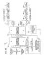
- FIGS. 2A and 2Bprovide a pictorial block diagram of a multi-stage laser beam positioning system of this invention.
- FIG. 3is a fragmentary pictorial side view showing a prior art galvanometer-driven mirror positioner of a type suitable for use with this invention.
- FIG. 4is a plan view showing preferred positions of Y-stage Abbe error sensors mounted on a Y-axis stage (workpiece stage) relative to a reference surface.
- FIG. 5is an end view showing preferred positions of the sensors mounted on the Y-axis stage of FIG. 4.
- FIG. 6is a side elevation view showing preferred positions of X-stage Abbe error sensors mounted on an X-axis stage (tool stage) relative to a reference surface.
- FIG. 7is an end view showing preferred positions of the sensors mounted on the X-axis stage of FIG. 6.
- FIG. 8is a plan view showing preferred positions of the sensors mounted on the X-axis stage of FIG. 6.
- FIG. 9is an oblique pictorial view showing a multi-head laser machining system employing the present invention.
- FIG. 10is a simplified electrical block diagram of a digital signal processing system including multiple fast stage signal processors employed in the multi-head laser machining system of FIG. 9.
- FIG. 11is a simplified electrical block diagram of one of multiple fast stage signal processors employed in the digital signal processing system of FIG. 10.
- FIG. 2shows a multi-stage tool positioner system 50 having positioning command execution capabilities in accordance with this invention.
- Positioner system 50is described herein only by way of example with reference to a single-head, laser-based hole cutting system that employs a digital signal processor (“DSP”) 52 to control a fast galvanometer positioner stage 54 (scanner or “fast stage 54 ”), a slow X-axis translation stage 56 (“slow stage 56 ”), and a slow Y-axis translation stage 58 (“slow stage 58 ”) to direct a laser beam 60 to target locations on a single workpiece 62 , such as an etched circuit board.
- DSPdigital signal processor
- the X-axis translation stage 56is supported by bearings on rails 46 and generally moves along an X-Z plane
- the Y-axis translation stage 58is supported by bearings on rails 48 and generally moves along an X-Y plane.
- both stages 56 and 58could alternatively be adapted to move in parallel planes and be inertially separated or dependent.
- positioner system 50employs high stiffness re-circulating or cross-roller bearing systems to support and direct the movement of stages 56 and 58 .
- a system control computer 63processes a tool path database stored in a database storage subsystem 64 .
- the databasecontains the desired processing parameters for cutting holes and/or profiles with laser beam 60 in workpiece 62 .
- the databaseis conventionally compiled using a tool path generating program, such as I-DEAS Generative Machining provided by Structural Dynamics Research Corporation located in Milford, Ohio.
- System control computer 63conveys parsed portions of the stored database to a laser controller 68 and position control portions of the database as a data stream to a delta process 70 .
- Delta process 70resolves the data stream into x and y components for delta position (“dp”), delta velocity (“dv”), and delta time (“dt”) for each intended change in the path of laser beam 60 across workpiece 62 . Consequently, each movement of laser beam 60 is defined in dp, dv, and dt components that are further processed by a position profiler 72 into move profiles including acceleration and/or constant velocity segment position signals.
- Delta process 70preferably generates the dp, dv, and dt components in accordance with a preferred BASIC language signal processing procedure described in U.S. Pat. Nos. 5,751,585 and 5,847,960 of Cutler et al., which are assigned to the assignee of this application.
- the dp, dv, and dt components generated by delta process 70are further processed by position profiler 72 into the move profile positioning signals required to move fast stage 54 and slow stages 56 and 58 as commanded by the database.
- positioner accelerationis proportional to motive force
- motive forceis proportional to electrical current supplied to a positioner driver such as a linear or rotary servo motor or a galvanometer coil. Therefore, the positioning signal produced by position profiler 72 is a series of “full-spectrum” half-sine profiled acceleration-inducing and constant velocity-inducing positioning steps that cause system movements.
- the full-spectrum bandwidthneed only be about 250 Hertz, a bandwidth sufficient to drive a typical galvanometer-driven mirror positioner at its maximum frequency.
- Instantaneous values of the full-spectrum positioning signalare generated by DSP 52 at a rate of about 10,000 points per second by employing the dp, dv, and dt components generated by delta process 70 as variables for a sine value generation program running in DSP 52 .
- the dp, dv, and dt componentsmay be employed to address and fetch associated sinusoidal waveform values stored in a sine value lookup table that is incorporated within DSP 52 .
- the resulting full-spectrum positioning signalhas acceleration and position components that are received by a profiling filter 78 having a constant signal propagation delay and a delay element 79 that compensates in DSP 52 for the constant signal propagation delay of profiling filter 78 .
- delay element 79delays the laser triggering pulses generated by position profiler 72 to coincide with the delayed movements of fast stage 54 and slow stages 56 and 58 .
- Profiling filter 78 and delay element 79also cooperate, as described below, to move slow stages 56 and 58 smoothly over the average position profile while limiting their acceleration to ⁇ 1 g and cooperate to limit fast stage 54 positioning movements to ⁇ 10 millimeters.
- the position componentis received by profiling filter 78 to produce filtered position command data for driving slow stages 56 and 58 .
- profiling filter 78is preferably a fourth-order low-pass filter.
- profiling filter 78produces filtered position command data having a constant time delay with respect to the half-sine positioning signal position component
- the constant time delayis compensated for by delay element 79 .
- Delay element 79is preferably implemented in DSP 52 as a programmed delay in conveying the half-sine positioning signal acceleration and position components from position profiler 72 to fast stage 54 signal processing elements, the first of which are adders 80 and 82 . Thereby, half-sine positioning signals directed to fast stage 54 are time synchronized with the filtered position commands directed to slow stages 56 and 58 .
- the acceleration component from position profiler 72is also filtered by profiling filter 78 to provide a filtered acceleration command to adder 80 and a feed forward process 94 .
- Adder 80functions as a high-pass filter by subtracting the filtered acceleration command from the acceleration component of the full-spectrum positioning signal to form a galvo acceleration feed forward signal, which is conveyed to a feed forward process 86 .
- the filtered position command from profiling filter 78 and the delayed position component of the half-sine positioning signalare conveyed respectively to adders 90 and 82 for processing and distribution, respectively, to slow stages 56 and 58 and fast stage 54 .
- a galvo filter 97 and a servo filter 98are conventional loop compensation filters that function to keep fast stage 54 and slow stages 56 and 58 stable.
- Profiling filter 78is implemented by cascading two or more second-order filters having critical damping ratios. As the number of cascaded filters increases beyond two, their cutoff frequencies increase by about the square root of the number of filters (e.g., two filters have cutoffs that are 1.414 times the cutoff for a single filter). Preferably two filters are cascaded to provide good smoothing while keeping the overall filter implementation simple.
- the preferred 38 radian per second cutoff frequency(about 6 Hertz (Hz)) is a very low frequency compared to the 10 kHz rate at which DSP 52 updates positioning data for slow stages 56 and 58 . If profiling filter 78 runs at the 10 kHz slow stage update frequency, the discrete filter coefficients become sensitive to roundoff errors because the poles of the discrete filter move close to the unit circle.
- Profiling filter 78also receives the acceleration command from position profiler 72 and generates the filtered acceleration command that is conveyed to servo feed forward process 94 and to adder 80 .
- the desired move profile commandsare preferably calculated at the 10 kHz updating rate, and the slow stage acceleration and actual (not commanded) position is subtracted therefrom at adders 80 and 82 to produce, respectively, the fast stage acceleration and position command signals.
- the fast stage acceleration command signalis processed through adder 80 and feed forward process 86 , while the fast stage position command signal is processed through adder 82 and galvo filter 97 .
- the processed fast stage signalsare combined in an adder 84 and conveyed to a galvanometer driver 88 .
- the slow stage filtered acceleration commandis processed through a feed forward process 94
- the slow stage filtered position commandis processed through adder 90 and servo filter 98 .
- the processed slow stage signalsare combined in an adder 92 and conveyed to a linear servo motor driver 96 .
- Galvanometer driver 88provides deflection control current to a pair of mirror deflecting galvanometers in fast stage 54
- servo motor driver 96provides control current to linear servo motors that control the positioning of slow stages 56 and 58 .
- FIG. 3shows a prior art galvanometer-driven mirror positioner 100 of a type suitable for use as fast stage 54 .
- Galvanometer driver 88(FIG. 2) provides rotational control current on conductors 102 to respective X-axis and Y-axis high-speed response D.C. motors 104 and 106 that rotate shafts 107 in bearings 108 to selectively pivot a pair of mirrors 110 and 112 that deflect laser beam 60 through an optional lens 114 to a predetermined target location on workpiece 62 .
- a nonbearing motion positionersuch as a piezoelectric element, a voice coil actuator, or other limited angle high-speed positioner device could be used in place of galvanometer-driven mirror positioner 100 in positioner system 50 .
- Two signalsare combined with the slow and fast stage position commands to reduce positional errors between the commanded position and the actual position of laser beam 60 on workpiece 62 .
- the delayed fast stage position command at adder 82 and the filtered slow stage position command at adder 90represent the ideal signal values required to cause proper positioning of stages 54 , 56 , and 58 .
- practical factorssuch as gravity, friction, mass, and inaccuracies in the full-spectrum positioning signal generated by position profiler 72 are not contemplated in the unmodified position commands.
- Position sensors 120 and 122may be well-known types employing rotating capacitor plates, linear and rotary encoder scales, or interferometer motion detectors together with appropriate analog-to-digital and/or digital-to-analog conversion techniques.
- sensed position data of fast stage 54 and slow stages 56 and 58are generated by position sensors 120 and 122 and subtracted from the commanded position at adder 82 to generate positional difference data that are combined in adder 84 with acceleration data from feed forward process 86 .
- sensed position data of slow stages 56 and 58are generated by position sensor 122 and subtracted from the commanded position at adder 90 to generate positional difference data that are combined in adder 92 with acceleration data from feed forward process 94 .
- Coordinated positioningis particularly beneficial for applications such as laser beam hole cutting that requires rapid movement between target locations along a tool path combined with pauses at each target location to fire the laser to cut a hole but, of course, is not limited to that application.
- Other features and preferred processing parameters of a conventional laser drilling systemare disclosed in U.S. Pat. No. 5,841,099 of Owen et al.
- FIGS. 4 and 5are respective plan and end views showing preferred positions of Y-stage Abbe sensors 124 mounted on Y-axis translation stage 58 relative to yaw reference surface 126 in accordance with an aspect of this invention
- FIGS. 6 - 8are respective side elevation, end, and plan views showing preferred positions of X-stage Abbe sensors 128 , 130 , 131 , and 132 mounted on X-axis translation stage 56 relative to yaw and roll reference surfaces 134 and pitch reference surface 136 in accordance with an aspect of this invention.
- Abbe sensors 124 , 128 , 130 , 131 , and 132are preferably non-contact, small and lightweight displacement sensors.
- the most preferred sensorsmeasure capacitance as a function of distance from a given reference surface.
- the Abbe sensorshave a gap range (distance between sensor and reference surface) of 50 ⁇ m plus or minus 25 ⁇ m and a resolution of less than 50 nm and preferably less than or equal to 10 nm. Skilled persons will appreciated that numerous other ranges are possible including a wider or narrower gap range and better resolution when the technology becomes cost effective.
- Non contact sensorsare preferred because they eliminate wear that might lead to inaccuracies.
- Preferred Abbe sensorsinclude Model PX405H series probes available from Lion Precision of St. Paul, Minn. Other suitable capacitance probes or sensors are available from ADE Technologies of Westwood, Mass and Micro-Epsilon of Ortenburg, Germany.
- Reference surfaces 126 , 134 , and 136may be formed on appropriate sides of bearing rails 46 and 48 as shown in FIG. 2B or may be otherwise positioned near but separated from translations stages 56 and 58 as shown in FIGS. 4 - 8 . (In FIGS. 4 - 8 , four Y-stage bearings 138 and three X-stage bearings 140 are depicted instead of rails 46 and 48 ).
- the reference surfacesare preferably the same length as the base for the stages or at least as long as the movement ranges along bearing rails 46 and 48 .
- the reference surfacesare preferably stable but do not need to be perfectly straight because the sensors are calibrated against the entire length of the surfaces so the corrections depend only on sensing small changes in the sensor readings and not on absolute accuracy of the sensor readings or stage positions.
- stages 56 and 58could be adapted to move in parallel planes and be inertially separated or dependent, the following description is, for convenience, presented herein only by way of example to addressing X and Y axis position errors in split-axis positioning system 70 where substantially flat (100 to 10,000 times larger in the X and Y dimensions than in Z dimension) workpiece 62 is carried on Y stage 58 and the tool (laser 76 ) is directed by X-stage 56 .
- the nominal on-axis position of Y stage 58is indicated by sensor 122 a , which is preferably a glass or metal scale encoder or a laser interferometer depending on desired positioning accuracy specifications.
- Y-stage yawtypically produces the most significant X and Y Abbe errors.
- the yaw erroris indicated by preferably a pair of Y-stage Abbe sensors 124 a and 124 b (generically sensors 124 ) that are preferably mounted as far apart as possible along Y axis 12 and as near to the top of the side of Y stage 58 , or a chuck that it may support, as practical.
- Reference surface 126is preferably integrated into rail 46 or the base of the Y stage assembly in a manner that results in as stable an indication of the stage yaw as possible as a function of other effects including bearing repeatability, temperature, and stage acceleration.
- the capacitances indicating the X components of the distance from the reference surface of the Abbe error detected by sensors 124 due to yaware preferably converted by a Y-stage yaw probe driver 145 into a DC voltage suitable for processing into Abbe error correction signals. These signals may be directed to separate X-Abbe and Y-Abbe error adders 142 and 144 before being routed to adder 82 and incorporated into scanner position commands.
- pitch, yaw, and roll of X stage 56can also cause significant X and Y position errors.
- the preferred split-axis configurationhas X stage 56 oriented on edge, such that the planes defined by the stages 56 and 58 are transverse and such that stages 56 and 58 are inertially separated.
- X stage 56is oriented vertically while Y stage 58 is oriented horizontally.
- pitch, yaw, and roll in this contextare defined with respect to the actual plane of movement of X stage 56 and not with respect to a more typical horizontal orientation.
- the nominal on-axis position of X stage 56is indicated by sensor 122 b , which is preferably a glass or metal scale encoder or a laser interferometer depending on desired positioning accuracy specifications.
- the X-stage Abbe sensors 128 , 130 , 131 , and 132may all be the same types as or different types from Y-stage sensors 124 .
- Sensors 128 a and 128 bare preferably mounted as far apart as possible along X axis 10 .
- sensors 130 and 131are preferably mounted as far apart as possible along X axis 10 .
- Sensor 132is preferably mounted to be planar with and as far apart as possible along Z axis 14 from sensor 131 .
- X stage 56is preferably kinematically mounted on three bearings 140 as shown in FIGS. 6 - 8 .
- changes in distance from reference surfaces 134 and 136 detected by X-stage Abbe sensors 128 , 130 , 131 , and 132will result predominately in movement of a plane associated with X stage 56 and not from distortion of X stage 56 .
- X-stage Abbe sensors 130 and 131detect distances from X-stage yaw reference surface 134 a and indicate changes in the yaw angle of the plane of X stage 56 .
- X-stage Abbe sensors 131 and 132detect distances from X-stage role reference surfaces 134 a and 134 b , respectively, and indicate changes in the roll angle of the plane of X-stage 56 .
- X-stage Abbe sensors 128detect distances from the pitch reference surface 136 and indicate changes in the pitch angle of X stage 56 .
- the capacitances indicating the X and Y components of the distance from the reference surface 134 a of the Abbe error detected by sensors 130 and 131 due to yaware preferably converted by an X-stage yaw probe driver 146 into a DC voltage suitable for processing into Abbe error correction signals.
- the capacitances indicating the X and Y components of the distances from the reference surfaces 134 a and 134 b of the Abbe error detected by sensors 131 and 132 due to rollare preferably converted by an X-stage roll probe driver 147 into a DC voltage suitable for processing into error correction signals.
- the capacitances indicating the X and Y components of the distances from the reference surface 136 of the Abbe error detected by sensors 128 due to pitchare preferably converted by an X-stage pitch probe driver 148 into a DC voltage suitable for processing into error correction signals.
- sensor 131feeds both yaw probe driver 145 and roll probe driver 146 .
- Suitable probe driversare well known to skilled persons; however, the Compact Probe Driver manufactured by Lion Precision is preferred.
- These yaw, roll, and pitch Abbe error correction signalsmay be directed to separate X-Abbe and Y-Abbe adders 142 and 144 before being routed to adder 82 and incorporated into scanner position commands.
- the X and Y position components that correspond to these Abbe errorsare calculated in real time as positioner system 50 moves and process workpiece 62 and are added to or superimposed on the scanner position commands to compensate for the Abbe position errors.
- These angular changesare combined with the geometry of the optics (including location of the beam path (or beam paths) relative to the stage and distance of the work from the stage) to indicate associated changes (errors) in effective beam position on the work.
- Fast responseis achieved by adding the Abbe error corrections to the scanner position at adder 82 because the bandwidth of the fast stage 54 is significantly higher than the bandwidth of the linear stages 56 and 58 .
- the Abbe error corrections resulting from the system of sensorscould be added to the linear stage position servo loop directly at adder 90 .
- This implementationwould be appropriate when fast stage 54 is replaced by a fixed beam positioner.
- a fixed beam positionerwould typically provide more precise beam positioning than is provided by fast stage 54 and would be employed in applications where greater accuracy might be desirable such as in severing micron or submicron sized links.
- Skilled personswill appreciate that X-axis stage 56 could be adapted so that fast stage 54 may be interchangeable with a fixed beam positioner, or that X-axis stage 56 may support both fast stage 54 and a fixed beam positioner simultaneously. In the latter case, Abbe error corrections would be fed to adder 82 whenever fast stage 54 is employed and fed to adder 90 whenever a fixed beam positioner is employed.
- FIG. 9shows a multi-head positioner 150 embodiment of this invention in which multiple workpieces 152 A, 152 B, 152 C, . . . 152 N are simultaneously processed.
- Multi-head positioner 150employs one each of slow stages 56 and 58 configured such that workpieces 152 are fixtured and carried on Y-axis slow stage 58 and multiple fast stages 154 A, 154 B, 154 C, . . . 154 N are carried on X-axis slow stage 56 .
- the roles of slow stages 56 and 58may be reversed, or two or more fast stages 154 may be carried by one or more X-axis slow stages 56 while Y-axis 58 carries a single workpiece 62 .
- the number N of fast stages 154 carried on slow stage 56is preferably limited to four, although N may vary with positioner types and applications.
- Each of workpieces 152has associated with it one or more processing tools, preferably a laser 156 A, 156 B, 156 C, . . . 156 N that directs processing energy toward associated fast stages 154 A, 154 B, 154 C, . . . 154 N by way of associated mirrors 158 A, 158 B, 158 C, . . . 158 N.
- Fast stages 154deflect the processing energy to target locations in substantially square, such as 20 by 20 millimeter processing fields 162 A, 162 B, 162 C, . . . 162 N located on associated workpieces 152 .
- Video cameras 160 A, 160 B, 160 C, . . . 160 Nare positioned on slow stage 56 for viewing associated processing fields 162 , sensing the alignments, offsets, rotations, and dimensional variations of workpieces 152 , and aiming and focusing lasers 156 .
- the same processing patternis duplicated on workpieces 152 by each of lasers 156 and fast stages 154 .
- processing pattern variationsmay be required to match the pattern to variations among workpiece geometries, scale factors, offsets, rotations, distortions.
- multi-head positioner 150can compensate for the above-described variations by employing programmable correction factors, described with reference to FIGS. 10 and 11, when driving each of fast stages 154 .
- the Abbe errorsindicating the degree to which a commanded tool position does not match a sensed target location, can be compensated for in a manner similar with that described with respect to FIGS. 2A, 2B, and 4 - 8 .
- FIG. 10shows how multi-rate positioner DSP 52 (FIG. 2) may be adapted to coordinate the positioning of multiple fast stages 154 and slow stages 56 and 58 , resulting in a multi-head DSP 170 .
- multi-head DSP 170receives from system control computer 63 dp, dv, and dt components that are further processed by position profiler 72 into half-sine profiled positioning signals.
- DSP 170also includes some of the same signal processing elements as DSP 52 , namely profiling filter 78 , delay element 79 , feed forward process 94 , servo driver 96 , slow stage 56 , and position sensor 122 . Because FIG. 10 is simplified, only X-axis slow stage 56 processing elements are shown. Skilled workers will understand that corresponding Y-axis elements are implied.
- FIG. 11shows a representative one of fast stage signal processors 172 receiving fast and slow stage positioning data from DSP 170 and correction data from system control computer 63 .
- the correction datainclude slow stage and workpiece related correction data that are conveyed to a geometry correction processor 180 and fast stage linearity and scale factor correction data that are conveyed to a fast stage correction processor 182 .
- Skilled personswill appreciate that if fast stages 154 are mounted on separate X-axis stages 56 , which preferably have synchronized movement but may be unsynchronized, then each such X-axis stage 56 may be commanded by its own processor 170 or subprocessor. Furthermore, each such stage 56 would preferably be equipped with its own position sensor 122 and five X-stage Abbe sensors to compensate for any Abbe errors associated with the individual stages.
- correction datamay be equation- or lookup table-based.
- correction data employed by geometry correction processor 180 and fast stage correction processorare preferably equation-based along lines described in U.S. Pat. No. 4,941,082 of Pailthorp et al. (“the '082 patent”), which is assigned to the assignee of this application and is incorporated herein by reference.
- Fast stage linearity and scale factor errorsare relatively constant and depend mostly on the individual characteristics of fast stages 154 . Therefore, fast stage correction processor 182 requires relatively small and infrequent correction data changes. Generating this correction data entails, for example, directing each of fast stages 154 to at least 13 calibration points on an associated calibration target as described in the '082 patent. A reflected energy detector senses any differences between the directed and actual target point locations and provides difference data to system control computer 63 for processing. The resulting correction data are conveyed to and stored in each fast stage correction processor 182 . Also, any differences between the directed and actual target point locations sensed by associated video cameras 160 are calibrated and compensated for. Slow stage linearity and scale factor errors are also relatively constant and do not, therefore, require frequent correction data changes.
- geometry correction processor 180requires relatively large correction data changes every time workpieces 152 are changed. Generating this correction data entails, for example, directing slow stages 56 and 58 to at least two, and preferably four, predetermined calibration targets on each associated workpiece 152 . Alternatively, in an embodiment where the vision system is working through the fast positioner, both the slow stages 56 and 58 and fast stages 154 are directed toward the calibration targets. These calibration targets may be, for example, corners, tooling holes, or photoetch targets of an ECB. Each video camera 160 senses differences between the directed and actual calibration target locations and provides difference data to system control computer 63 for processing. The resulting correction data for each workpiece 152 are conveyed to and stored in the associated geometry correction processor 180 .
- corrected positioning data for the Y-axisare conveyed from correction processors 180 and 182 to feed forward process 86 , galvo driver 88 , and fast stage 154 .
- Position feedback dataare generated by position sensor 120 (as in FIG. 2A) and combined for correction in adders 184 and 84 . Skilled workers will understand that the same process applies to X-axis fast positioning.
- each fast stageis preferably limited to an 18 by 18 millimeter positioning range within its 20 by 20 millimeter maximum linear positioning range. The remaining 2 millimeters of positioning range is employed for applying the above-described corrections.
- a typical tool application employing positioner system 50 and including Abbe error correctionis laser cutting of holes, such as blind via holes, in multilayer ECBs or other workpieces 62 .
- Multilayer ECBsare typically manufactured by registering, stacking together, laminating, and pressing multiple 0.05- to 0.08-millimeter thick circuit board layers. Each layer typically contains a different interconnection pad and conductor pattern, which after processing constitutes a complex electrical component mounting and interconnection assembly.
- the component and conductor density trend of ECBsis increasing together with that of integrated circuits. Therefore, the positioning accuracy and dimensional tolerances of holes in ECBs is increasing proportionally.
- the pressing stepcauses expansion and dimensional variations that lead to scale factor and orthogonality variations among the ECBs.
- fixturing variationscan cause dimensional rotation and offset errors among the ECBs.
- ECB thickness variationsmake it difficult to mechanically drill holes having an accurately predetermined depth.
- Positioner systems 50 or 150solve the above-described problems as follows. Two to four calibration targets can be etched at predetermined locations, preferably one at each corner, on each ECB. Video cameras 160 sense differences between the commanded and actual calibration target locations and provide difference data to system control computer 63 for processing. The resulting correction data are conveyed to and stored in geometry correction processor 180 .
- Two calibration targetsprovide sufficient difference data to system control computer 63 to correct for rotation and offset variations among the ECBs.
- Three calibration targetsprovide sufficient difference data to system control computer 63 to correct for rotation, offset, scale factor, and orthogonality variations among the ECBs.
- Adding a fourth calibration targetfurther allows for correction of trapezoidal distortion in each of the ECBs.
- ECB thickness variationsare readily accommodated by the ⁇ 0.13-millimeter ( ⁇ 0.005 inch) laser depth of field.
- blind via holespresents a difficult challenge for any hole processing tool because of the tight depth, diameter, and positioning tolerances involved. This is because blind via holes are typically processed through a first conductor layer (e.g., copper, aluminum, gold, nickel, silver, palladium, tin, and lead), through one or more dielectric layers (e.g., polyimide, FR-4 resin, benzocyclobutene, bismaleimide triazine, cyanate ester-based resin, ceramic), and up to, but not through a second conductor layer. The resulting hole is plated with a conductive material to electrically connect the first and second conductor layers. Blind via processing windows are presented in detail U.S. Pat. No. 5,841,099 of Owen et al.
- multi-head positioner 150is configured as an ECB blind via cutting apparatus in which N equals an even number, such as 2, 4, or 6, but preferably 4.
- Lasers 156 A and 156 Care UV lasers (wavelength is less than about 400 nanometers and preferably about 355 or 266 nm), and lasers 156 B and 156 N are IR lasers (wavelength is in a range from about 1,000 nanometers to about 10,000 nanometers, preferably about 9,000 nanometers). Because the UV and IR lasers have substantially different wavelengths, mirrors 158 and optics for fast stages 154 are configured for compatibility with each associated laser's wavelength.
- UV lasers 156 A and 156 Care capable of cutting both the first conductor layer and the dielectric layer in a suitable manner. However, the laser power levels and pulse repetition rates are carefully controlled to prevent unacceptable damage to the second conductor layer. This results in a narrow “process window.” Therefore, UV lasers 156 A and 156 C are preferably employed to cut through only the first conductor layer and a portion of the dielectric layer, a process that has a wide process window. Once the first conductor layer is removed by the UV lasers 156 , IR lasers 156 B and 156 N, which have a wide process window for cutting through the remaining dielectric layer without cutting through or damaging the second conductor layer, are employed to remove the last portion of the dielectric layer.
- the ECB blind via cutting apparatusemploys UV lasers 156 A and 156 C to cut through the first conductor layers of workpieces 152 A and 152 C and IR lasers 156 B and 156 N to cut through the dielectric layers on workpieces 152 B and 152 N.
- the time required for UV lasers 156 A and 156 C to cut through the conductor layersis typically longer than the time required by IR lasers 152 B and 152 N to cut through the dielectric layer. Therefore, the longer processing time dictates the processing throughput. Because the target locations are substantially identical for all tools on multi-tool positioner 150 , the different processing times are accounted for by providing appropriately different laser power levels and pulse repetition rates for the UV and IR lasers.
- UV lasers 154 A and 154 Chave a beam diameter of only about 20 micrometers
- multi-tool positioner 150must cause the UV beam to follow a spiral or circular path to cut such holes in a conductor layer. Therefore, cutting these relatively large holes takes a proportionally longer time.
- IR lasers 154 B and 154 Nhave a beam diameter of about 400 micrometers, which is about 20 times the UV laser beam diameter. Therefore, when cutting these relatively large diameter holes through the dielectric layers, at least some portion of the IR laser beam will cover the entire hole while the UV beam follows the spiral or circular path to cut a hole in a conductor layer. Under these circumstances, the IR laser beams are on the target locations for a relatively longer time and the different effective processing times are again accounted for by providing appropriately different laser power levels and pulse repetition rates for the UV and IR lasers.
- a single lasermay be shared among multiple workpieces by employing suitable power splitting devices. It is also envisioned that switchable-wavelength lasers may be employed in this invention.
- This inventionprovides an improved combination of positioning accuracy, positioning speed, minimized or eliminated stopping time, nonpanelized tool path databases, and minimized fast stage movement range that dramatically improves processing throughput while reducing workpiece rejects caused by dimensional and orientation variations.
- portions of this inventionmay be implemented differently from the laser beam micro-machining implementation described above.
- a wide variety of toolsin single or multi-headed configurations, may be moved by the fast positioner stage, such as micro-dimensioned drills, punches, lasers, laser beams, radiation beams, particle beams, beam producing devices, microscopes, lenses, optical instruments, and cameras.
- many different positioning devicesmay be employed in different combinations drawn from among galvanometers, voice coils, piezoelectric transducers, stepper motors, and lead screw positioners.
- the DSPsneed not be completely digital and may, for example, include any suitable combination of analog and digital subcircuits.
- the positioning signal profiles, spectral bandwidth and amplitudes, and filter characteristics described hereinmay all be modified to suit the requirements of other positioning applications.
Landscapes
- Physics & Mathematics (AREA)
- Optics & Photonics (AREA)
- Engineering & Computer Science (AREA)
- General Physics & Mathematics (AREA)
- Mechanical Engineering (AREA)
- Plasma & Fusion (AREA)
- Automation & Control Theory (AREA)
- Manufacturing & Machinery (AREA)
- Human Computer Interaction (AREA)
- Container, Conveyance, Adherence, Positioning, Of Wafer (AREA)
- Control Of Position Or Direction (AREA)
- Length Measuring Devices By Optical Means (AREA)
- Analysing Materials By The Use Of Radiation (AREA)
- Radar Systems Or Details Thereof (AREA)
- Attitude Control For Articles On Conveyors (AREA)
- Automatic Control Of Machine Tools (AREA)
- Transmission And Conversion Of Sensor Element Output (AREA)
- Navigation (AREA)
Abstract
Description
- This application derives priority from U.S. Provisional Patent Application No. 60/175,993, filed Jan. 11, 2000.[0001]
- This invention relates to systems or methods for positioning one or multiple “tools,” such as laser beams or other radiation beams, relative to target locations on one or multiple workpieces and, in particular, to a system that accurately compensates for Abbe errors associated with the movement of one or more stages of such a beam positioning system.[0002]
- A variety of technologies employ tools to micro-machine, or deposit patterns or materials on target locations on a workpiece. For example, a micro-dimensioned punch may be used to punch holes in a thin metal plate; a laser may be used to precisely machine or selectively erode metallic, crystalline, or amorphous specimens; and ion beams may be used to selectively implant charged particles into an integrated circuit. All of the above-mentioned processes share a common requirement for accurately and rapidly positioning a pertinent tool to target locations on the workpiece.[0003]
- The following background is presented herein only by way of example to laser beam positioning systems, but skilled persons will appreciate that the description is applicable to tool positioning systems in general. Conventional tool positioning systems, and particularly beam-positioning systems, typically provide movement within a three-dimensional coordinate system and can be characterized in several ways.[0004]
- Traditional positioning systems are characterized by X-Y translation tables in which the workpiece is secured to an upper stage that is supported by a lower stage. Such systems typically move the workpiece relative to a fixed beam position and are commonly referred to as stacked stage positioning systems because the lower stage supports the inertial mass of the upper stage and the workpiece. These positioning systems have relatively good positioning accuracy because interferometers are typically used along each axis to determine the absolute position of each stage.[0005]
- In U.S. Pat. No. 4,532,402 of Overbeck, a high-speed short-movement positioner (“fast positioner”), such as a galvanometer, is supported by the upper stage of an X-Y translation table (“slow positioner”) and the upper stage and the workpiece are supported by the lower stage. The combined movement of the two positioners entails first moving the slow positioner to a known location near a target location on the workpiece, stopping the slow positioner, moving the fast positioner to the exact target location, stopping the fast positioner, causing the tool to operate on the target location, and then repeating the process for the next target location.[0006]
- However, the combined system of Overbeck is also a stacked stage positioning system and suffers from many of the same serious drawbacks as the aforementioned fixed beam system. The starting, stopping, and change of direction delays associated with the inertial mass of the stages and fast positioner unduly increase the time required for the tool to process the workpiece. Overbeck's system also imposes a serious drawback upon a computer-based machine tool control file or “database” that typically commands the tool to move to a series of predetermined target locations across the workpiece. The database positioning the tool across the workpiece must be “panelized” into abutting segments that each fit within the limited movement range of the fast positioner when the size of large circuit patterns exceeds this movement range.[0007]
- U.S. Pat. Nos. 5,751,585 and 5,847,960 of Cutler et al. describe split-axis positioning systems, in which the upper stage is not supported by, and moves independently from, the lower stage and in which the workpiece is carried on one axis or stage while the tool is carried on the other axis or stage. These positioning systems have one or more upper stages, which each support a fast positioner, and can process one or multiple workpieces simultaneously at high throughput rates because the independently supported stages each carry less inertial mass and can accelerate, decelerate, or change direction more quickly than can those of a stacked stage system. Thus, because the mass of one stage is not carried on the other stage, the resonance frequencies for a given load are increased. Furthermore, the slow and fast positioners are adapted to move, without necessarily stopping, in response to a stream of positioning command data while coordinating their individually moving positions to produce temporarily stationary tool positions over target locations defined by the database. These split-axis, multirate positioning systems reduce the fast positioner movement range limitations of prior systems while providing significantly increased tool processing throughput and can work from panelized or unpanelized databases.[0008]
- Such split-axis positioning systems are becoming even more advantageous as the overall size and weight of the workpieces increase, utilizing longer and hence more massive stages. At the same time, feature sizes are continuing to decrease, causing the need for dimensional precision to increase, and split-axis systems are more likely to exhibit rotational errors that introduce Abbe errors, which are errors indicative of the physical separation between the effective position of a stage and the indicated position of the stage. Abbe errors are typically caused by imperfections or thermal variations in the bearings upon which the stages slide and/or alignment or acceleration imperfections of the drive mechanisms that provide movement to the stages.[0009]
- FIG. 1 shows three mutually perpendicular translational motion axes, such as[0010]
X axis 10,Y axis 12, andZ axis 14 that define a three-dimensional coordinate system 16, and three mutually perpendicular rotational motion axes (hereafter referred to as aroll axis 18, apitch axis 20, and a yaw axis22). Skilled workers typically refer to roll as an angular rotation aboutX-axis 10, pitch as an angular rotation about Y-axis 12, and yaw as an angular rotation about Z-axis 14. - Although laser interferometer systems can be used to indicate and compensate for certain Abbe errors, such systems are costly and heavy because they typically require reference mirrors that are nearly as long as the combined stage length plus the length of travel, e.g. as much as two times the travel distance. Such mirrors are difficult, if not impossible, to procure for the long travel dimensions of large stages, such as with a lengthwise dimension of 76 to 92 cm (30-36 inches), needed to accommodate larger workpieces. Furthermore, split-axis systems would require at least two interferometers for each stage and/or a very complex system of optics to rat -indicate angle and position, and the additive weight of the interferometers would increase the inertial load on the stages at the expense of frequency response time to changes in momentum.[0011]
- U.S. Pat. No. 5,699,621 of Trumper et al. discloses the use of small range displacement transducers to indicate pitch, yaw, and roll angle errors. Trumper et al. correct angular errors by controlling the bearing gap with electromagnets that require the use of a highly compliant magnetic or air bearing system. The correction speed of the Trumper et al. system is limited to the bandwidth of the linear stage system and therefore has similar mass versus bandwidth limitations as stacked stage positioning systems.[0012]
- A less expensive and/or less massive and very accurate Abbe error correction system or method is therefore desirable.[0013]
- An object of the present invention is to provide a method or apparatus that employs non-contact small displacement sensors, such as capacitive sensors, to determine Abbe errors due to mechanical stage pitch, yaw and roll that are not indicated by an on-axis position indicator, such as a linear scale encoder or laser interferometer, and a means to compensate for such Abbe errors.[0014]
- Another object of the invention is to employ such sensors to determine and correct Abbe errors due to linear bearing variability or distortions associated with acceleration or temperature gradients.[0015]
- The present invention provides a cost effective means to determine and compensate for linear stage positioning system Abbe errors that are errors at the effective position of the system that are not indicated by a position indicator such as a metal or glass scale encoder or laser interferometer due to pitch, yaw, or roll of the linear stage and the resulting physical distance between the effective position and the indicated position of a stage. To minimize cost, the system is calibrated against precision X and Y position reference standards so the corrections depend only on sensing small changes in the sensor readings and not on absolute accuracy of the sensor readings. Although the present invention is preferred for use in split-axis positioning systems, it can be employed in stacked stage systems to reduce their manufacturing costs. Although a linear scale encoder can be employed to indicate the nominal on-axis stage position to reduce costs further, a laser interferometer can be used when a greater level of accuracy and/or resolution is desired.[0016]
- Additional objects and advantages of this invention will be apparent from the following detailed description of preferred embodiments thereof which proceeds with reference to the accompanying drawings.[0017]
- FIG. 1 shows six axes, including three mutually perpendicular translational motion axes, X, Y, and Z, and three mutually perpendicular rotational motion axes, roll, pitch, and yaw.[0018]
- FIGS. 2A and 2B provide a pictorial block diagram of a multi-stage laser beam positioning system of this invention.[0019]
- FIG. 3 is a fragmentary pictorial side view showing a prior art galvanometer-driven mirror positioner of a type suitable for use with this invention.[0020]
- FIG. 4 is a plan view showing preferred positions of Y-stage Abbe error sensors mounted on a Y-axis stage (workpiece stage) relative to a reference surface.[0021]
- FIG. 5 is an end view showing preferred positions of the sensors mounted on the Y-axis stage of FIG. 4.[0022]
- FIG. 6 is a side elevation view showing preferred positions of X-stage Abbe error sensors mounted on an X-axis stage (tool stage) relative to a reference surface.[0023]
- FIG. 7 is an end view showing preferred positions of the sensors mounted on the X-axis stage of FIG. 6.[0024]
- FIG. 8 is a plan view showing preferred positions of the sensors mounted on the X-axis stage of FIG. 6.[0025]
- FIG. 9 is an oblique pictorial view showing a multi-head laser machining system employing the present invention.[0026]
- FIG. 10 is a simplified electrical block diagram of a digital signal processing system including multiple fast stage signal processors employed in the multi-head laser machining system of FIG. 9.[0027]
- FIG. 11 is a simplified electrical block diagram of one of multiple fast stage signal processors employed in the digital signal processing system of FIG. 10.[0028]
- FIGS. 2A and 2B (generically FIG. 2) show a multi-stage[0029]
tool positioner system 50 having positioning command execution capabilities in accordance with this invention.Positioner system 50 is described herein only by way of example with reference to a single-head, laser-based hole cutting system that employs a digital signal processor (“DSP”)52 to control a fast galvanometer positioner stage54 (scanner or “fast stage 54”), a slow X-axis translation stage56 (“slow stage 56”), and a slow Y-axis translation stage58 (“slow stage 58”) to direct alaser beam 60 to target locations on asingle workpiece 62, such as an etched circuit board. - With reference to FIG. 1, in a preferred split-axis embodiment, the[0030]
X-axis translation stage 56 is supported by bearings onrails 46 and generally moves along an X-Z plane, and the Y-axis translation stage 58 is supported by bearings onrails 48 and generally moves along an X-Y plane. Skilled persons will appreciate that bothstages positioner system 50 employs high stiffness re-circulating or cross-roller bearing systems to support and direct the movement ofstages - A[0031]
system control computer 63 processes a tool path database stored in adatabase storage subsystem 64. The database contains the desired processing parameters for cutting holes and/or profiles withlaser beam 60 inworkpiece 62. The database is conventionally compiled using a tool path generating program, such as I-DEAS Generative Machining provided by Structural Dynamics Research Corporation located in Milford, Ohio.System control computer 63 conveys parsed portions of the stored database to alaser controller 68 and position control portions of the database as a data stream to adelta process 70.Delta process 70 resolves the data stream into x and y components for delta position (“dp”), delta velocity (“dv”), and delta time (“dt”) for each intended change in the path oflaser beam 60 acrossworkpiece 62. Consequently, each movement oflaser beam 60 is defined in dp, dv, and dt components that are further processed by aposition profiler 72 into move profiles including acceleration and/or constant velocity segment position signals. - [0032]
Delta process 70 preferably generates the dp, dv, and dt components in accordance with a preferred BASIC language signal processing procedure described in U.S. Pat. Nos. 5,751,585 and 5,847,960 of Cutler et al., which are assigned to the assignee of this application. - Referring again to FIG. 2, the dp, dv, and dt components generated by[0033]
delta process 70 are further processed byposition profiler 72 into the move profile positioning signals required to movefast stage 54 andslow stages position profiler 72 is a series of “full-spectrum” half-sine profiled acceleration-inducing and constant velocity-inducing positioning steps that cause system movements. The full-spectrum bandwidth need only be about 250 Hertz, a bandwidth sufficient to drive a typical galvanometer-driven mirror positioner at its maximum frequency. - Instantaneous values of the full-spectrum positioning signal are generated by[0034]
DSP 52 at a rate of about 10,000 points per second by employing the dp, dv, and dt components generated bydelta process 70 as variables for a sine value generation program running inDSP 52. Alternatively, the dp, dv, and dt components may be employed to address and fetch associated sinusoidal waveform values stored in a sine value lookup table that is incorporated withinDSP 52. - The resulting full-spectrum positioning signal has acceleration and position components that are received by a[0035]
profiling filter 78 having a constant signal propagation delay and adelay element 79 that compensates inDSP 52 for the constant signal propagation delay ofprofiling filter 78. For example,delay element 79 delays the laser triggering pulses generated byposition profiler 72 to coincide with the delayed movements offast stage 54 andslow stages Profiling filter 78 anddelay element 79 also cooperate, as described below, to moveslow stages fast stage 54 positioning movements to ±10 millimeters. - The position component is received by profiling[0036]
filter 78 to produce filtered position command data for drivingslow stages Profiling filter 78 is preferably a fourth-order low-pass filter. - Because profiling[0037]
filter 78 produces filtered position command data having a constant time delay with respect to the half-sine positioning signal position component, the constant time delay is compensated for bydelay element 79. Delayelement 79 is preferably implemented inDSP 52 as a programmed delay in conveying the half-sine positioning signal acceleration and position components fromposition profiler 72 tofast stage 54 signal processing elements, the first of which areadders fast stage 54 are time synchronized with the filtered position commands directed to slowstages - The acceleration component from[0038]
position profiler 72 is also filtered by profilingfilter 78 to provide a filtered acceleration command to adder80 and afeed forward process 94.Adder 80 functions as a high-pass filter by subtracting the filtered acceleration command from the acceleration component of the full-spectrum positioning signal to form a galvo acceleration feed forward signal, which is conveyed to afeed forward process 86. Likewise, the filtered position command from profilingfilter 78 and the delayed position component of the half-sine positioning signal are conveyed respectively toadders stages fast stage 54. Agalvo filter 97 and aservo filter 98 are conventional loop compensation filters that function to keepfast stage 54 andslow stages - Profiling[0039]
filter 78 is implemented by cascading two or more second-order filters having critical damping ratios. As the number of cascaded filters increases beyond two, their cutoff frequencies increase by about the square root of the number of filters (e.g., two filters have cutoffs that are 1.414 times the cutoff for a single filter). Preferably two filters are cascaded to provide good smoothing while keeping the overall filter implementation simple. - For[0040]
profiling filter 78, the preferred38 radian per second cutoff frequency (about 6 Hertz (Hz)) is a very low frequency compared to the 10 kHz rate at whichDSP 52 updates positioning data forslow stages filter 78 runs at the 10 kHz slow stage update frequency, the discrete filter coefficients become sensitive to roundoff errors because the poles of the discrete filter move close to the unit circle.Profiling filter 78 also receives the acceleration command fromposition profiler 72 and generates the filtered acceleration command that is conveyed to servo feedforward process 94 and to adder80. - The desired move profile commands are preferably calculated at the 10 kHz updating rate, and the slow stage acceleration and actual (not commanded) position is subtracted therefrom at[0041]
adders - The fast stage acceleration command signal is processed through[0042]
adder 80 and feedforward process 86, while the fast stage position command signal is processed throughadder 82 andgalvo filter 97. The processed fast stage signals are combined in anadder 84 and conveyed to agalvanometer driver 88. - Likewise, the slow stage filtered acceleration command is processed through a[0043]
feed forward process 94, while the slow stage filtered position command is processed throughadder 90 andservo filter 98. The processed slow stage signals are combined in anadder 92 and conveyed to a linearservo motor driver 96. - [0044]
Galvanometer driver 88 provides deflection control current to a pair of mirror deflecting galvanometers infast stage 54, andservo motor driver 96 provides control current to linear servo motors that control the positioning ofslow stages - FIG. 3 shows a prior art galvanometer-driven[0045]
mirror positioner 100 of a type suitable for use asfast stage 54. Galvanometer driver88 (FIG. 2) provides rotational control current onconductors 102 to respective X-axis and Y-axis high-speedresponse D.C. motors 104 and106 that rotateshafts 107 inbearings 108 to selectively pivot a pair ofmirrors laser beam 60 through anoptional lens 114 to a predetermined target location onworkpiece 62. - Alternatively, a nonbearing motion positioner, such as a piezoelectric element, a voice coil actuator, or other limited angle high-speed positioner device could be used in place of galvanometer-driven[0046]
mirror positioner 100 inpositioner system 50. - Likewise with reference to FIG. 2, alternative accurate rotary or linear positioner mechanisms may be substituted for the linear servo motors driving[0047]
slow stages positioner system 50, linear motors that preferentially respond to the slow stage position command are preferred. - Two signals are combined with the slow and fast stage position commands to reduce positional errors between the commanded position and the actual position of[0048]
laser beam 60 onworkpiece 62. The delayed fast stage position command atadder 82 and the filtered slow stage position command atadder 90 represent the ideal signal values required to cause proper positioning ofstages position profiler 72 are not contemplated in the unmodified position commands. - The practical factors are accounted for by sensing the actual positions of[0049]
stages position sensors adders DSP 52. Note thatadder 82 in the fast stage positioning path receives position feedback data from bothposition sensors Position sensors - As[0050]
laser beam 60 undergoes movement acrossworkpiece 62, the sensed beam position is continuously compared to the commanded beam position, with the positional difference representing a degree to which the practical factors have caused positioning errors. In particular, sensed position data offast stage 54 andslow stages position sensors adder 82 to generate positional difference data that are combined inadder 84 with acceleration data from feed forwardprocess 86. Likewise, sensed position data ofslow stages position sensor 122 and subtracted from the commanded position atadder 90 to generate positional difference data that are combined inadder 92 with acceleration data from feed forwardprocess 94. - Coordinated positioning is particularly beneficial for applications such as laser beam hole cutting that requires rapid movement between target locations along a tool path combined with pauses at each target location to fire the laser to cut a hole but, of course, is not limited to that application. Other features and preferred processing parameters of a conventional laser drilling system are disclosed in U.S. Pat. No. 5,841,099 of Owen et al.[0051]
- FIGS. 4 and 5 are respective plan and end views showing preferred positions of Y-[0052]
stage Abbe sensors 124 mounted on Y-axis translation stage 58 relative to yawreference surface 126 in accordance with an aspect of this invention, and FIGS.6-8 are respective side elevation, end, and plan views showing preferred positions ofX-stage Abbe sensors X-axis translation stage 56 relative to yaw and roll reference surfaces134 and pitchreference surface 136 in accordance with an aspect of this invention. - With reference to FIGS.[0053]2B and4-8,
Abbe sensors - Reference surfaces[0054]126,134, and136 may be formed on appropriate sides of bearing
rails stage bearings 138 and threeX-stage bearings 140 are depicted instead ofrails 46 and48). The reference surfaces are preferably the same length as the base for the stages or at least as long as the movement ranges along bearingrails - Although[0055]
stages axis positioning system 70 where substantially flat (100 to 10,000 times larger in the X and Y dimensions than in Z dimension) workpiece62 is carried onY stage 58 and the tool (laser76) is directed byX-stage 56. - With reference again to FIGS. 2A, 2B,[0056]4 and5, the nominal on-axis position of
Y stage 58 is indicated bysensor 122a, which is preferably a glass or metal scale encoder or a laser interferometer depending on desired positioning accuracy specifications. In a split-axis configuration, Y-stage yaw typically produces the most significant X and Y Abbe errors. The yaw error is indicated by preferably a pair of Y-stage Abbe sensors124aand124b(generically sensors124) that are preferably mounted as far apart as possible alongY axis 12 and as near to the top of the side ofY stage 58, or a chuck that it may support, as practical.Reference surface 126 is preferably integrated intorail 46 or the base of the Y stage assembly in a manner that results in as stable an indication of the stage yaw as possible as a function of other effects including bearing repeatability, temperature, and stage acceleration. - The capacitances indicating the X components of the distance from the reference surface of the Abbe error detected by[0057]
sensors 124 due to yaw are preferably converted by a Y-stageyaw probe driver 145 into a DC voltage suitable for processing into Abbe error correction signals. These signals may be directed to separate X-Abbe and Y-Abbe error adders - With reference again to FIGS. 2A, 2B, and[0058]6-8, pitch, yaw, and roll of
X stage 56 can also cause significant X and Y position errors. The preferred split-axis configuration, as shown in the figures, hasX stage 56 oriented on edge, such that the planes defined by thestages X stage 56 is oriented vertically whileY stage 58 is oriented horizontally. Thus, pitch, yaw, and roll in this context are defined with respect to the actual plane of movement ofX stage 56 and not with respect to a more typical horizontal orientation. - The nominal on-axis position of[0059]
X stage 56 is indicated bysensor 122b, which is preferably a glass or metal scale encoder or a laser interferometer depending on desired positioning accuracy specifications. TheX-stage Abbe sensors stage sensors 124.Sensors X axis 10. Similarly,sensors X axis 10.Sensor 132 is preferably mounted to be planar with and as far apart as possible alongZ axis 14 fromsensor 131. - Because[0060]
X stage 56 is preferably kinematically mounted on threebearings 140 as shown in FIGS.6-8, changes in distance fromreference surfaces 134 and136 detected byX-stage Abbe sensors X stage 56 and not from distortion ofX stage 56.X-stage Abbe sensors yaw reference surface 134aand indicate changes in the yaw angle of the plane ofX stage 56.X-stage Abbe sensors X-stage 56.X-stage Abbe sensors 128 detect distances from thepitch reference surface 136 and indicate changes in the pitch angle ofX stage 56. - The capacitances indicating the X and Y components of the distance from the[0061]
reference surface 134aof the Abbe error detected bysensors yaw probe driver 146 into a DC voltage suitable for processing into Abbe error correction signals. Similarly, the capacitances indicating the X and Y components of the distances from the reference surfaces134aand134bof the Abbe error detected bysensors roll probe driver 147 into a DC voltage suitable for processing into error correction signals. Similarly, the capacitances indicating the X and Y components of the distances from thereference surface 136 of the Abbe error detected bysensors 128 due to pitch are preferably converted by an X-stagepitch probe driver 148 into a DC voltage suitable for processing into error correction signals. Skilled persons will note thatsensor 131 feeds bothyaw probe driver 145 and rollprobe driver 146. Suitable probe drivers are well known to skilled persons; however, the Compact Probe Driver manufactured by Lion Precision is preferred. These yaw, roll, and pitch Abbe error correction signals may be directed to separate X-Abbe and Y-Abbe adders - The X and Y position components that correspond to these Abbe errors are calculated in real time as[0062]
positioner system 50 moves andprocess workpiece 62 and are added to or superimposed on the scanner position commands to compensate for the Abbe position errors. These angular changes are combined with the geometry of the optics (including location of the beam path (or beam paths) relative to the stage and distance of the work from the stage) to indicate associated changes (errors) in effective beam position on the work. Fast response is achieved by adding the Abbe error corrections to the scanner position atadder 82 because the bandwidth of thefast stage 54 is significantly higher than the bandwidth of thelinear stages - However, the Abbe error corrections resulting from the system of sensors could be added to the linear stage position servo loop directly at[0063]
adder 90. This implementation would be appropriate whenfast stage 54 is replaced by a fixed beam positioner. A fixed beam positioner would typically provide more precise beam positioning than is provided byfast stage 54 and would be employed in applications where greater accuracy might be desirable such as in severing micron or submicron sized links. Skilled persons will appreciate thatX-axis stage 56 could be adapted so thatfast stage 54 may be interchangeable with a fixed beam positioner, or thatX-axis stage 56 may support bothfast stage 54 and a fixed beam positioner simultaneously. In the latter case, Abbe error corrections would be fed to adder82 wheneverfast stage 54 is employed and fed to adder90 whenever a fixed beam positioner is employed. - FIG. 9 shows a[0064]
multi-head positioner 150 embodiment of this invention in whichmultiple workpieces Multi-head positioner 150 employs one each ofslow stages slow stage 58 and multiplefast stages slow stage 56. Of course, the roles ofslow stages fast stages 154 may be carried by one or more X-axisslow stages 56 while Y-axis 58 carries asingle workpiece 62. - As the number of[0065]
fast stages 154 carried onslow stage 56 increases, their accumulated mass becomes increasingly difficult to accelerate. Therefore, the number N offast stages 154 carried onslow stage 56 is preferably limited to four, although N may vary with positioner types and applications. - Each of workpieces[0066]152 has associated with it one or more processing tools, preferably a
laser fast stages mirrors Fast stages 154 deflect the processing energy to target locations in substantially square, such as 20 by 20millimeter processing fields - [0067]
Video cameras slow stage 56 for viewing associated processing fields162, sensing the alignments, offsets, rotations, and dimensional variations of workpieces152, and aiming and focusing lasers156. - In the preferred embodiment, the same processing pattern is duplicated on workpieces[0068]152 by each of lasers156 and
fast stages 154. However, in some processing applications, processing pattern variations may be required to match the pattern to variations among workpiece geometries, scale factors, offsets, rotations, distortions. Alternatively, it may be desirable to have one or more lasers156 simultaneously processing different, but preferably nominally identical or repetitive (slave to a single Y stage), patterns on the same workpiece152. It may also be necessary to correct for fast stage nonlinearities and mounting inconsistences introduced by mounting position variations among workpieces152 mounted onslow stage 58. Unlike prior multi-spindle drilling machines,multi-head positioner 150 can compensate for the above-described variations by employing programmable correction factors, described with reference to FIGS. 10 and 11, when driving each offast stages 154. Similarly, the Abbe errors, indicating the degree to which a commanded tool position does not match a sensed target location, can be compensated for in a manner similar with that described with respect to FIGS. 2A, 2B, and4-8. - FIG. 10 shows how multi-rate positioner DSP[0069]52 (FIG. 2) may be adapted to coordinate the positioning of multiple
fast stages 154 andslow stages multi-head DSP 170. In like manner toDSP 52,multi-head DSP 170 receives fromsystem control computer 63 dp, dv, and dt components that are further processed byposition profiler 72 into half-sine profiled positioning signals.DSP 170 also includes some of the same signal processing elements asDSP 52, namely profilingfilter 78,delay element 79, feedforward process 94,servo driver 96,slow stage 56, andposition sensor 122. Because FIG. 10 is simplified, only X-axisslow stage 56 processing elements are shown. Skilled workers will understand that corresponding Y-axis elements are implied. - Only a single[0070]
system control computer 63 is required to driveslow stages stage signal processors system control computer 63. In this way, fast stage position commands and current slow stage position data are received by each of faststage signal processors 172 such that each offast stages 154 is directed to a common set of target locations that are further positionable by unique error correction data. If only a singleX-axis stage 56 is employed to carry multiplefast stages 154 and a single Y-axis stage 58 is employed to carry one or multiple workpieces152, then the Abbe error detection system shown and described in connection with FIGS. 2A, 2B, and4-8 can be employed without modification, and the Abbeerror correction data 190 can be fed to adder80 of FIG. 10 or faststage correction processor 180 of FIG. 11 as shown. - FIG. 11 shows a representative one of fast[0071]
stage signal processors 172 receiving fast and slow stage positioning data fromDSP 170 and correction data fromsystem control computer 63. The correction data include slow stage and workpiece related correction data that are conveyed to ageometry correction processor 180 and fast stage linearity and scale factor correction data that are conveyed to a faststage correction processor 182. Skilled persons will appreciate that iffast stages 154 are mounted on separateX-axis stages 56, which preferably have synchronized movement but may be unsynchronized, then each suchX-axis stage 56 may be commanded by itsown processor 170 or subprocessor. Furthermore, eachsuch stage 56 would preferably be equipped with itsown position sensor 122 and five X-stage Abbe sensors to compensate for any Abbe errors associated with the individual stages. - The correction data may be equation- or lookup table-based. However, correction data employed by[0072]
geometry correction processor 180 and fast stage correction processor are preferably equation-based along lines described in U.S. Pat. No. 4,941,082 of Pailthorp et al. (“the '082 patent”), which is assigned to the assignee of this application and is incorporated herein by reference. - Fast stage linearity and scale factor errors are relatively constant and depend mostly on the individual characteristics of[0073]
fast stages 154. Therefore, faststage correction processor 182 requires relatively small and infrequent correction data changes. Generating this correction data entails, for example, directing each offast stages 154 to at least 13 calibration points on an associated calibration target as described in the '082 patent. A reflected energy detector senses any differences between the directed and actual target point locations and provides difference data to system controlcomputer 63 for processing. The resulting correction data are conveyed to and stored in each faststage correction processor 182. Also, any differences between the directed and actual target point locations sensed by associated video cameras160 are calibrated and compensated for. Slow stage linearity and scale factor errors are also relatively constant and do not, therefore, require frequent correction data changes. - On the other hand, workpiece-related errors are relatively variable and depend mostly on workpiece placement, offset, rotation, and dimensional variations among workpieces[0074]152. Therefore,
geometry correction processor 180 requires relatively large correction data changes every time workpieces152 are changed. Generating this correction data entails, for example, directingslow stages slow stages fast stages 154 are directed toward the calibration targets. These calibration targets may be, for example, corners, tooling holes, or photoetch targets of an ECB. Each video camera160 senses differences between the directed and actual calibration target locations and provides difference data to system controlcomputer 63 for processing. The resulting correction data for each workpiece152 are conveyed to and stored in the associatedgeometry correction processor 180. - For each fast[0075]
stage signal processor 172, corrected positioning data for the Y-axis are conveyed fromcorrection processors forward process 86,galvo driver 88, andfast stage 154. Position feedback data are generated by position sensor120 (as in FIG. 2A) and combined for correction inadders - In applying the correction data to[0076]
fast stages 154, each fast stage is preferably limited to an 18 by 18 millimeter positioning range within its 20 by 20 millimeter maximum linear positioning range. The remaining 2 millimeters of positioning range is employed for applying the above-described corrections. - The foregoing describes signal processing for a single axis of motion for each of the fast and slow positioner stages. Skilled workers will readily understand how to replicate the signal processing to coordinate the motion of both axes, both stages, and single or multiple fast positioners.[0077]
- A typical tool application employing[0078]
positioner system 50 and including Abbe error correction is laser cutting of holes, such as blind via holes, in multilayer ECBs orother workpieces 62. Multilayer ECBs are typically manufactured by registering, stacking together, laminating, and pressing multiple 0.05- to 0.08-millimeter thick circuit board layers. Each layer typically contains a different interconnection pad and conductor pattern, which after processing constitutes a complex electrical component mounting and interconnection assembly. The component and conductor density trend of ECBs is increasing together with that of integrated circuits. Therefore, the positioning accuracy and dimensional tolerances of holes in ECBs is increasing proportionally. - Unfortunately, the pressing step causes expansion and dimensional variations that lead to scale factor and orthogonality variations among the ECBs. Moreover, when multiple ECBs (workpieces[0079]152) are attached to slow
stage 58, fixturing variations can cause dimensional rotation and offset errors among the ECBs. Adding to that, ECB thickness variations make it difficult to mechanically drill holes having an accurately predetermined depth. - [0080]
Positioner systems computer 63 for processing. The resulting correction data are conveyed to and stored ingeometry correction processor 180. - Two calibration targets provide sufficient difference data to system control[0081]
computer 63 to correct for rotation and offset variations among the ECBs. Three calibration targets provide sufficient difference data to system controlcomputer 63 to correct for rotation, offset, scale factor, and orthogonality variations among the ECBs. Adding a fourth calibration target further allows for correction of trapezoidal distortion in each of the ECBs. - ECB thickness variations are readily accommodated by the ±0.13-millimeter (±0.005 inch) laser depth of field.[0082]
- Processing blind via holes presents a difficult challenge for any hole processing tool because of the tight depth, diameter, and positioning tolerances involved. This is because blind via holes are typically processed through a first conductor layer (e.g., copper, aluminum, gold, nickel, silver, palladium, tin, and lead), through one or more dielectric layers (e.g., polyimide, FR-4 resin, benzocyclobutene, bismaleimide triazine, cyanate ester-based resin, ceramic), and up to, but not through a second conductor layer. The resulting hole is plated with a conductive material to electrically connect the first and second conductor layers. Blind via processing windows are presented in detail U.S. Pat. No. 5,841,099 of Owen et al.[0083]
- Referring again to FIG. 9,[0084]
multi-head positioner 150 is configured as an ECB blind via cutting apparatus in which N equals an even number, such as 2, 4, or 6, but preferably 4.Lasers lasers fast stages 154 are configured for compatibility with each associated laser's wavelength. - [0085]
UV lasers UV lasers IR lasers UV lasers workpieces 152A and152C andIR lasers workpieces - The time required for[0086]
UV lasers IR lasers multi-tool positioner 150, the different processing times are accounted for by providing appropriately different laser power levels and pulse repetition rates for the UV and IR lasers. - Some applications require cutting relatively large hole diameters of about 200 micrometers or less. Because[0087]
UV lasers multi-tool positioner 150 must cause the UV beam to follow a spiral or circular path to cut such holes in a conductor layer. Therefore, cutting these relatively large holes takes a proportionally longer time. However,IR lasers - If suitable laser power is available, a single laser may be shared among multiple workpieces by employing suitable power splitting devices. It is also envisioned that switchable-wavelength lasers may be employed in this invention.[0088]
- This invention provides an improved combination of positioning accuracy, positioning speed, minimized or eliminated stopping time, nonpanelized tool path databases, and minimized fast stage movement range that dramatically improves processing throughput while reducing workpiece rejects caused by dimensional and orientation variations.[0089]
- Skilled workers will recognize that portions of this invention may be implemented differently from the laser beam micro-machining implementation described above. For example, a wide variety of tools, in single or multi-headed configurations, may be moved by the fast positioner stage, such as micro-dimensioned drills, punches, lasers, laser beams, radiation beams, particle beams, beam producing devices, microscopes, lenses, optical instruments, and cameras. Also, many different positioning devices may be employed in different combinations drawn from among galvanometers, voice coils, piezoelectric transducers, stepper motors, and lead screw positioners. The DSPs need not be completely digital and may, for example, include any suitable combination of analog and digital subcircuits. Of course, the positioning signal profiles, spectral bandwidth and amplitudes, and filter characteristics described herein may all be modified to suit the requirements of other positioning applications.[0090]
- It will be obvious to skilled workers that many other changes may be made to the details of the above-described embodiments of this invention without departing from the underlying principles thereof. The scope of the present invention should, therefore, be determined only by the following claims.[0091]
Claims (46)
Priority Applications (1)
| Application Number | Priority Date | Filing Date | Title |
|---|---|---|---|
| US09/755,950US6430465B2 (en) | 2000-01-11 | 2001-01-05 | Abbe error correction system and method |
Applications Claiming Priority (2)
| Application Number | Priority Date | Filing Date | Title |
|---|---|---|---|
| US17599300P | 2000-01-11 | 2000-01-11 | |
| US09/755,950US6430465B2 (en) | 2000-01-11 | 2001-01-05 | Abbe error correction system and method |
Publications (2)
| Publication Number | Publication Date |
|---|---|
| US20010029674A1true US20010029674A1 (en) | 2001-10-18 |
| US6430465B2 US6430465B2 (en) | 2002-08-06 |
Family
ID=22642517
Family Applications (1)
| Application Number | Title | Priority Date | Filing Date |
|---|---|---|---|
| US09/755,950Expired - LifetimeUS6430465B2 (en) | 2000-01-11 | 2001-01-05 | Abbe error correction system and method |
Country Status (11)
| Country | Link |
|---|---|
| US (1) | US6430465B2 (en) |
| EP (1) | EP1275036B1 (en) |
| JP (1) | JP4860870B2 (en) |
| KR (1) | KR100755335B1 (en) |
| CN (1) | CN100437407C (en) |
| AT (1) | ATE308071T1 (en) |
| AU (1) | AU2001227690A1 (en) |
| CA (1) | CA2396259A1 (en) |
| DE (1) | DE60114397T2 (en) |
| TW (1) | TW472177B (en) |
| WO (1) | WO2001052004A1 (en) |
Cited By (22)
| Publication number | Priority date | Publication date | Assignee | Title |
|---|---|---|---|---|
| US20020125227A1 (en)* | 2001-03-12 | 2002-09-12 | Yunlong Sun | Quasi-CW diode-pumped, solid-state UV laser system and method employing same |
| US20030047541A1 (en)* | 2001-03-12 | 2003-03-13 | Yunlong Sun | Quasi-CW diode-pumped, solid-state harmonic laser system and method employing same |
| US20040140426A1 (en)* | 2002-02-15 | 2004-07-22 | Psia Corporation | Scanning probe microscope with improved probe head mount |
| US20040176861A1 (en)* | 2003-03-06 | 2004-09-09 | Asml Netherlands B.V. | System for controlling a position of a mass |
| WO2005116783A1 (en)* | 2004-05-27 | 2005-12-08 | K.U.Leuven Research And Development | A measurement configuration based on linear scales able to measure to a target also moving perpendicular to the measurement axis |
| US20060018350A1 (en)* | 2004-07-20 | 2006-01-26 | Lightwave Electronics Corporation | Laser burst boosting method and apparatus |
| US20080029491A1 (en)* | 2006-07-20 | 2008-02-07 | Gsi Group Corporation | System and method for laser processing at non-constant velocities |
| US20080094593A1 (en)* | 2006-09-01 | 2008-04-24 | Nikon Corporation | Movable body drive method and movable body drive system, pattern formation method and apparatus, exposure method and apparatus, device manufacturing method, and calibration method |
| US20080094592A1 (en)* | 2006-08-31 | 2008-04-24 | Nikon Corporation | Movable body drive method and movable body drive system, pattern formation method and apparatus, exposure method and apparatus, and device manufacturing method |
| US20080094604A1 (en)* | 2006-09-01 | 2008-04-24 | Nikon Corporation | Movable body drive method and movable body drive system, pattern formation method and apparatus, exposure method and apparatus, and device manufacturing method |
| US20080106722A1 (en)* | 2006-08-31 | 2008-05-08 | Nikon Corporation | Movable body drive system and movable body drive method, pattern formation apparatus and method, exposure apparatus and method, device manufacturing method, and decision-making method |
| WO2007092498A3 (en)* | 2006-02-06 | 2008-07-24 | Rave Llc | Method and apparatus for controlling sample position during material removal or addition |
| US20080201971A1 (en)* | 2007-02-26 | 2008-08-28 | Vistec Semiconductor Systems Gmbh | Method for eliminating sources of error in the system correction of a coordinate measuring machine |
| US20080218713A1 (en)* | 2006-08-31 | 2008-09-11 | Nikon Corporation | Movable body drive method and movable body drive system, pattern formation method and apparatus, exposure method and apparatus, and device manufacturing method |
| US8100543B1 (en)* | 2007-06-12 | 2012-01-24 | Nvidia Corporation | Display system and method equipped with at least one steerable deflecting mirror |
| US8118440B1 (en) | 2007-06-12 | 2012-02-21 | Nvidia Corporation | Capture system and method equipped with at least one steerable deflecting mirror |
| US20130126491A1 (en)* | 2010-04-23 | 2013-05-23 | Osram Opto Semiconductors Gmbh | Method and Device for Machining a Workpiece by Means of a Laser |
| US20130325162A1 (en)* | 2011-02-25 | 2013-12-05 | Innse-Berardi S.P.A. | Machine tools which compensate for thermal deformation |
| DE10296913B4 (en) | 2001-06-08 | 2014-08-21 | Electro Scientific Industries, Inc. | Segmented laser cutting |
| CN112643228A (en)* | 2021-01-21 | 2021-04-13 | 上海维宏电子科技股份有限公司 | Method, system, device, processor and storage medium for realizing capacitance compensation control on cutting head temperature drift in laser cutting system |
| US20220074737A1 (en)* | 2019-02-08 | 2022-03-10 | Dutch United Instruments B.V. | Positioning system for positioning an object |
| CN116088414A (en)* | 2021-11-08 | 2023-05-09 | 苏州维嘉科技股份有限公司 | Deviation correction method, device, equipment and storage medium, laminated plate production line |
Families Citing this family (58)
| Publication number | Priority date | Publication date | Assignee | Title |
|---|---|---|---|---|
| EP1202833B1 (en)* | 1999-07-23 | 2003-12-03 | Heidelberg Instruments Mikrotechnik GmbH | Method of producing microbore holes |
| US6676878B2 (en) | 2001-01-31 | 2004-01-13 | Electro Scientific Industries, Inc. | Laser segmented cutting |
| JP2002096234A (en)* | 2000-09-20 | 2002-04-02 | Mori Seiki Co Ltd | Control method and control device for drive mechanism in NC machine tool |
| DE10156781C1 (en)* | 2001-11-19 | 2003-02-27 | Siemens Ag | Active compensator for mechanical vibrations and deformations has machine point moved in accordance with preset intended position value |
| US6706998B2 (en) | 2002-01-11 | 2004-03-16 | Electro Scientific Industries, Inc. | Simulated laser spot enlargement |
| JP2004001067A (en)* | 2002-03-28 | 2004-01-08 | Fanuc Ltd | Laser beam machine and laser beam machining method |
| KR100992120B1 (en)* | 2003-03-13 | 2010-11-04 | 삼성전자주식회사 | Silicon Crystallization System and Silicon Crystallization Method |
| US20040204777A1 (en)* | 2003-04-14 | 2004-10-14 | Alon Harpaz | Precision motion control using feed forward of acceleration |
| DE10317363B3 (en)* | 2003-04-15 | 2004-08-26 | Siemens Ag | Laser-powered hole boring machine for manufacture of substrates for electrical switching circuits has scanning system with oscillating mirrors and focusing lens |
| JP3680064B2 (en)* | 2003-04-21 | 2005-08-10 | ファナック株式会社 | Numerical controller |
| CN100544877C (en)* | 2003-10-17 | 2009-09-30 | 通明国际科技公司 | Flexible scan field |
| KR101290665B1 (en)* | 2004-06-07 | 2013-07-30 | 일렉트로 싸이언티픽 인더스트리이즈 인코포레이티드 | Aom modulation techniques for improving laser system performance |
| US7133187B2 (en)* | 2004-06-07 | 2006-11-07 | Electro Scientific Industries, Inc. | AOM modulation techniques employing plurality of transducers to improve laser system performance |
| US7203569B2 (en)* | 2004-08-31 | 2007-04-10 | General Electric Company | Machine tool control methods and designs for fabricating mesoscopic surface structures on substrates |
| US20060065085A1 (en)* | 2004-09-29 | 2006-03-30 | General Electric Company | Multi element tool designs for modifying surface characteristics of substrates |
| JP4513574B2 (en)* | 2005-01-12 | 2010-07-28 | ウシオ電機株式会社 | Stage equipment |
| US7826063B2 (en)* | 2005-04-29 | 2010-11-02 | Zygo Corporation | Compensation of effects of atmospheric perturbations in optical metrology |
| US7512452B2 (en)* | 2005-06-13 | 2009-03-31 | Mauro George E | Positioning system for eliminating lost motion effect |
| JP4291313B2 (en)* | 2005-09-13 | 2009-07-08 | 住友重機械工業株式会社 | Head operation control device, control method, and stage device |
| US7638731B2 (en) | 2005-10-18 | 2009-12-29 | Electro Scientific Industries, Inc. | Real time target topography tracking during laser processing |
| US7605343B2 (en)* | 2006-05-24 | 2009-10-20 | Electro Scientific Industries, Inc. | Micromachining with short-pulsed, solid-state UV laser |
| JP5276595B2 (en)* | 2006-11-15 | 2013-08-28 | ザイゴ コーポレーション | Distance measuring interferometer and encoder measuring system used in lithography tools |
| US7894075B2 (en)* | 2006-12-11 | 2011-02-22 | Zygo Corporation | Multiple-degree of freedom interferometer with compensation for gas effects |
| US7812965B2 (en)* | 2006-12-11 | 2010-10-12 | Zygo Corporation | Multiple-degree of freedom interferometer with compensation for gas effects |
| US8173931B2 (en)* | 2008-06-13 | 2012-05-08 | Electro Scientific Industries, Inc. | Automatic recipe management for laser processing a work piece |
| US8024060B2 (en)* | 2008-06-16 | 2011-09-20 | Electro Scientific Industries, Inc. | Method for defining safe zones in laser machining systems |
| US8450641B2 (en)* | 2008-10-10 | 2013-05-28 | Ipg Microsystems Llc | Laser machining systems and methods with moving laser scanning stage(s) providing force cancellation |
| TWI523720B (en) | 2009-05-28 | 2016-03-01 | 伊雷克托科學工業股份有限公司 | Acousto-optic deflector applications in laser processing of features in a workpiece, and related laser processing method |
| US8925931B2 (en) | 2010-04-29 | 2015-01-06 | Black & Decker Inc. | Oscillating tool |
| US9073195B2 (en) | 2010-04-29 | 2015-07-07 | Black & Decker Inc. | Universal accessory for oscillating power tool |
| US9186770B2 (en) | 2010-04-29 | 2015-11-17 | Black & Decker Inc. | Oscillating tool attachment feature |
| CN102259503B (en)* | 2010-05-26 | 2014-02-12 | 宏恒胜电子科技(淮安)有限公司 | Automatic coding system and its usage method |
| JP5014471B2 (en)* | 2010-06-30 | 2012-08-29 | ファナック株式会社 | Numerical controller for multi-axis machines |
| KR102143502B1 (en)* | 2010-10-22 | 2020-08-13 | 일렉트로 싸이언티픽 인더스트리이즈 인코포레이티드 | Laser processing systems and methods for beam dithering and skiving |
| US9149923B2 (en) | 2010-11-09 | 2015-10-06 | Black & Decker Inc. | Oscillating tools and accessories |
| CN102540783B (en)* | 2010-12-31 | 2014-11-12 | 上海微电子装备有限公司 | Automatic calibration device and method for abbe cosine error of interferometer |
| USD832666S1 (en) | 2012-07-16 | 2018-11-06 | Black & Decker Inc. | Oscillating saw blade |
| US9397587B2 (en)* | 2013-11-20 | 2016-07-19 | Massachusetts Institute Of Technology | Multi-actuator design and control for a high-speed/large-range nanopositioning system |
| US9269149B2 (en)* | 2014-05-08 | 2016-02-23 | Orbotech Ltd. | Calibration of a direct-imaging system |
| CN104654997B (en)* | 2015-02-14 | 2018-03-13 | 中国科学院测量与地球物理研究所 | A kind of multiple degrees of freedom differential capacitance calibration device for displacement sensor |
| CN104759753B (en)* | 2015-03-30 | 2016-08-31 | 江苏大学 | The co-ordination of multisystem automatization improves the method for induced with laser cavitation reinforcement |
| WO2017044646A1 (en) | 2015-09-09 | 2017-03-16 | Electro Scientific Industries, Inc. | Laser processing apparatus, methods of laser-processing workpieces and related arrangements |
| JP6761590B2 (en)* | 2015-12-24 | 2020-09-30 | 株式会社リコー | Optical processing equipment |
| TWI564131B (en)* | 2015-12-29 | 2017-01-01 | Hiwin Tech Corp | Method and method of path planning for array pick - up using robotic arm The compensator used by the path planning method |
| CN105574287B (en)* | 2016-01-07 | 2018-10-02 | 安徽理工大学 | Machine tool error modeling method based on bidimensional Abbe error and Instantaneous center |
| WO2018126078A1 (en) | 2016-12-30 | 2018-07-05 | Electro Scientific Industries, Inc. | Method and system for extending optics lifetime in laser processing apparatus |
| US10265778B2 (en) | 2017-01-16 | 2019-04-23 | Black & Decker Inc. | Accessories for oscillating power tools |
| USD814900S1 (en) | 2017-01-16 | 2018-04-10 | Black & Decker Inc. | Blade for oscillating power tools |
| CN110650818B (en) | 2017-05-25 | 2021-08-27 | 三菱电机株式会社 | Laser processing apparatus |
| EP3749481B1 (en)* | 2018-02-07 | 2023-11-22 | Micro Products Company | Material positioner for welding apparatus and method |
| KR102655354B1 (en) | 2018-06-05 | 2024-04-08 | 일렉트로 싸이언티픽 인더스트리이즈 인코포레이티드 | Laser processing device, its operation method and method of processing workpieces using it |
| JP7431550B2 (en)* | 2019-10-03 | 2024-02-15 | 三井精機工業株式会社 | Adjustment method that enables higher accuracy of machine tools |
| US11969845B2 (en) | 2020-02-18 | 2024-04-30 | Hiwin Mikrosystem Corp. | Quick measurement module |
| DE102020104708B4 (en) | 2020-02-22 | 2022-01-27 | Hiwin Mikrosystem Corp. | Fast measurement module |
| DE102020204232B4 (en)* | 2020-04-01 | 2023-05-17 | P&L Gmbh & Co. Kg | Machine tool with high-precision machining capability and operating method |
| CN111338291B (en)* | 2020-04-07 | 2023-07-14 | 湖北文理学院 | Abbe error compensation method and system based on machine tool positioning accuracy measurement |
| TWI728812B (en)* | 2020-05-19 | 2021-05-21 | 鴻勁精密股份有限公司 | Correction method for a moving device |
| CN112066881B (en)* | 2020-09-15 | 2021-10-22 | 成都明杰科技有限公司 | Use method of control system for precisely measuring Abbe error |
Family Cites Families (40)
| Publication number | Priority date | Publication date | Assignee | Title |
|---|---|---|---|---|
| US3786332A (en) | 1969-03-19 | 1974-01-15 | Thomson Houston Comp Francaise | Micro positioning apparatus |
| FR2330997A1 (en) | 1975-11-07 | 1977-06-03 | Sagem | IMPROVEMENTS IN PROCESSES AND MACHINES FOR MEASURING PART DIMENSIONS |
| GB2042719B (en) | 1978-12-27 | 1983-03-09 | Ferranti Ltd | Positional measuring apparatus |
| US4378482A (en) | 1981-04-27 | 1983-03-29 | Control Data Corporation | Electron-beam stage X-Y positioning instrumentation |
| US4532402A (en) | 1983-09-02 | 1985-07-30 | Xrl, Inc. | Method and apparatus for positioning a focused beam on an integrated circuit |
| US4724525A (en) | 1984-12-12 | 1988-02-09 | Moore Special Tool Co., Inc. | Real-time data collection apparatus for use in multi-axis measuring machine |
| US4782598A (en) | 1985-09-19 | 1988-11-08 | Digital Electronic Automation, Inc. | Active error compensation in a coordinate measuring machine |
| US4676649A (en)* | 1985-11-27 | 1987-06-30 | Compact Spindle Bearing Corp. | Multi-axis gas bearing stage assembly |
| GB8616431D0 (en) | 1986-07-05 | 1986-08-13 | Renishaw Plc | Locating co-ordinates of object |
| DE3743902A1 (en) | 1986-12-26 | 1988-07-07 | Mitsubishi Electric Corp | LASER MACHINING DEVICE |
| US4877939A (en) | 1987-01-30 | 1989-10-31 | Duley Walter W | Means of enhancing laser processing efficiency of metals |
| US4820899A (en) | 1987-03-03 | 1989-04-11 | Nikon Corporation | Laser beam working system |
| US4789770A (en) | 1987-07-15 | 1988-12-06 | Westinghouse Electric Corp. | Controlled depth laser drilling system |
| FR2620223B1 (en) | 1987-09-09 | 1994-03-25 | Institut Superieur Etat Surface | METHOD FOR SLIDING A MOBILE MEDIUM ON A REFERENCE SURFACE AND ASSOCIATED DEVICE |
| US4939678A (en) | 1987-11-19 | 1990-07-03 | Brown & Sharpe Manufacturing Company | Method for calibration of coordinate measuring machine |
| GB8730169D0 (en) | 1987-12-24 | 1988-02-03 | Renishaw Plc | Optical apparatus for use with interferometric measuring devices |
| JPH01266983A (en) | 1988-04-20 | 1989-10-24 | Hitachi Seiko Ltd | Piercing machine for printed board |
| US4941082A (en) | 1988-04-25 | 1990-07-10 | Electro Scientific Industries, Inc. | Light beam positioning system |
| JP2704734B2 (en)* | 1988-09-05 | 1998-01-26 | キヤノン株式会社 | Stage positioning correction method and apparatus |
| US5315526A (en)* | 1989-12-07 | 1994-05-24 | Okuma Corporation | Numerically controlled lathe |
| US5280677A (en) | 1990-05-17 | 1994-01-25 | Canon Kabushiki Kaisha | Positioning mechanism |
| US5255199A (en)* | 1990-12-14 | 1993-10-19 | Martin Marietta Energy Systems, Inc. | Cutting tool form compensaton system and method |
| US5290992A (en) | 1992-10-07 | 1994-03-01 | International Business Machines Corporation | Apparatus for maximizing light beam utilization |
| US5408318A (en) | 1993-08-02 | 1995-04-18 | Nearfield Systems Incorporated | Wide range straightness measuring stem using a polarized multiplexed interferometer and centered shift measurement of beam polarization components |
| US5798195A (en)* | 1993-09-24 | 1998-08-25 | Nikon Corporation | Stepping accuracy measuring method |
| DE4342312A1 (en) | 1993-12-11 | 1995-06-14 | Zeiss Carl Fa | Method for correcting vibration-related measurement errors in coordinate measuring machines |
| DE4436507A1 (en) | 1994-10-13 | 1996-04-18 | Zeiss Carl Fa | Coordinate measurement of workpiece using coordinate measuring unit |
| US5841099A (en) | 1994-07-18 | 1998-11-24 | Electro Scientific Industries, Inc. | Method employing UV laser pulses of varied energy density to form depthwise self-limiting blind vias in multilayered targets |
| US5552888A (en) | 1994-12-02 | 1996-09-03 | Nikon Precision, Inc. | Apparatus for measuring position of an X-Y stage |
| US5847960A (en)* | 1995-03-20 | 1998-12-08 | Electro Scientific Industries, Inc. | Multi-tool positioning system |
| US5751585A (en)* | 1995-03-20 | 1998-05-12 | Electro Scientific Industries, Inc. | High speed, high accuracy multi-stage tool positioning system |
| CN2238417Y (en)* | 1995-04-11 | 1996-10-23 | 中国科学院长春光学精密机械研究所 | Sensor for measuring micro linear displacement |
| JP3153099B2 (en) | 1995-04-20 | 2001-04-03 | キヤノン株式会社 | Positioning device |
| US5832416A (en) | 1995-09-01 | 1998-11-03 | Brown & Sharpe Manufacturing Company | Calibration system for coordinate measuring machine |
| US5812420A (en) | 1995-09-05 | 1998-09-22 | Nikon Corporation | Vibration-preventive apparatus and exposure apparatus |
| JP3460074B2 (en) | 1995-11-24 | 2003-10-27 | 株式会社トプコン | Electronic level horizontal error correction mechanism |
| US5699621A (en) | 1996-02-21 | 1997-12-23 | Massachusetts Institute Of Technology | Positioner with long travel in two dimensions |
| JPH09317767A (en)* | 1996-05-28 | 1997-12-09 | Nippon Seiko Kk | Positioning device |
| JPH1041205A (en)* | 1996-07-18 | 1998-02-13 | Nikon Corp | Scanning exposure equipment |
| JPH11233403A (en)* | 1998-02-10 | 1999-08-27 | Nikon Corp | Stage adjustment method and scanning exposure apparatus using the same |
- 2001
- 2001-01-05EPEP01901835Apatent/EP1275036B1/ennot_activeExpired - Lifetime
- 2001-01-05KRKR1020027008743Apatent/KR100755335B1/ennot_activeExpired - Fee Related
- 2001-01-05ATAT01901835Tpatent/ATE308071T1/ennot_activeIP Right Cessation
- 2001-01-05JPJP2001552159Apatent/JP4860870B2/ennot_activeExpired - Fee Related
- 2001-01-05AUAU2001227690Apatent/AU2001227690A1/ennot_activeAbandoned
- 2001-01-05CNCNB018036155Apatent/CN100437407C/ennot_activeExpired - Fee Related
- 2001-01-05CACA002396259Apatent/CA2396259A1/ennot_activeAbandoned
- 2001-01-05WOPCT/US2001/000484patent/WO2001052004A1/enactiveIP Right Grant
- 2001-01-05DEDE60114397Tpatent/DE60114397T2/ennot_activeExpired - Lifetime
- 2001-01-05USUS09/755,950patent/US6430465B2/ennot_activeExpired - Lifetime
- 2001-01-08TWTW090100352Apatent/TW472177B/ennot_activeIP Right Cessation
Cited By (68)
| Publication number | Priority date | Publication date | Assignee | Title |
|---|---|---|---|---|
| US6806440B2 (en) | 2001-03-12 | 2004-10-19 | Electro Scientific Industries, Inc. | Quasi-CW diode pumped, solid-state UV laser system and method employing same |
| US20030047541A1 (en)* | 2001-03-12 | 2003-03-13 | Yunlong Sun | Quasi-CW diode-pumped, solid-state harmonic laser system and method employing same |
| US20020125227A1 (en)* | 2001-03-12 | 2002-09-12 | Yunlong Sun | Quasi-CW diode-pumped, solid-state UV laser system and method employing same |
| US6781090B2 (en) | 2001-03-12 | 2004-08-24 | Electro Scientific Industries, Inc. | Quasi-CW diode-pumped, solid-state harmonic laser system and method employing same |
| DE10296913B4 (en) | 2001-06-08 | 2014-08-21 | Electro Scientific Industries, Inc. | Segmented laser cutting |
| US20040140424A1 (en)* | 2002-02-15 | 2004-07-22 | Psia Corporation | Scanning probe microscope with improved probe tip mount |
| US6945100B2 (en) | 2002-02-15 | 2005-09-20 | Psia Corporation | Scanning probe microscope with improved probe tip mount |
| US6951129B2 (en)* | 2002-02-15 | 2005-10-04 | Psia Corporation | Scanning probe microscope with improved probe head mount |
| US20040140426A1 (en)* | 2002-02-15 | 2004-07-22 | Psia Corporation | Scanning probe microscope with improved probe head mount |
| US20040176861A1 (en)* | 2003-03-06 | 2004-09-09 | Asml Netherlands B.V. | System for controlling a position of a mass |
| US7209219B2 (en)* | 2003-03-06 | 2007-04-24 | Asml Netherlands B.V. | System for controlling a position of a mass |
| WO2005116783A1 (en)* | 2004-05-27 | 2005-12-08 | K.U.Leuven Research And Development | A measurement configuration based on linear scales able to measure to a target also moving perpendicular to the measurement axis |
| US7478481B2 (en)* | 2004-05-27 | 2009-01-20 | K.U. Leuven Research & Development | Measurement configuration based on linear scales able to measure to a target also moving perpendicular to the measurement axis |
| US20080040941A1 (en)* | 2004-05-27 | 2008-02-21 | Dominiek Reynaerts | Measurement Configuration Based on Linear Scales Able to Measure to a Target Also Moving Perpendicular to the Measurement Axis |
| EP2431826A1 (en)* | 2004-05-27 | 2012-03-21 | K.U.Leuven Research & Development | A measurement configuration based on linear scales able to measure to a target also moving perpendicular to the measurement axis |
| US20060018350A1 (en)* | 2004-07-20 | 2006-01-26 | Lightwave Electronics Corporation | Laser burst boosting method and apparatus |
| US7352784B2 (en) | 2004-07-20 | 2008-04-01 | Jds Uniphase Corporation | Laser burst boosting method and apparatus |
| WO2007092498A3 (en)* | 2006-02-06 | 2008-07-24 | Rave Llc | Method and apparatus for controlling sample position during material removal or addition |
| US8084706B2 (en)* | 2006-07-20 | 2011-12-27 | Gsi Group Corporation | System and method for laser processing at non-constant velocities |
| US20080029491A1 (en)* | 2006-07-20 | 2008-02-07 | Gsi Group Corporation | System and method for laser processing at non-constant velocities |
| US20120083049A1 (en)* | 2006-07-20 | 2012-04-05 | Gsi Group Corporation | System and method for laser processing at non-constant velocities |
| US10073359B2 (en) | 2006-08-31 | 2018-09-11 | Nikon Corporation | Movable body drive system and movable body drive method, pattern formation apparatus and method, exposure apparatus and method, device manufacturing method, and decision-making method |
| US10338482B2 (en) | 2006-08-31 | 2019-07-02 | Nikon Corporation | Movable body drive method and movable body drive system, pattern formation method and apparatus, exposure method and apparatus, and device manufacturing method |
| US10162274B2 (en) | 2006-08-31 | 2018-12-25 | Nikon Corporation | Movable body drive method and system, pattern formation method and apparatus, exposure method and apparatus for driving movable body based on measurement value of encoder and information on flatness of scale, and device manufacturing method |
| EP2071611A4 (en)* | 2006-08-31 | 2011-04-20 | Nikon Corp | Mobile body drive system and mobile body drive method, pattern formation apparatus and method, exposure apparatus and method, device manufacturing method, and decision method |
| US8013982B2 (en) | 2006-08-31 | 2011-09-06 | Nikon Corporation | Movable body drive method and system, pattern formation method and apparatus, exposure method and apparatus for driving movable body based on measurement value of encoder and information on flatness of scale, and device manufacturing method |
| US20080218713A1 (en)* | 2006-08-31 | 2008-09-11 | Nikon Corporation | Movable body drive method and movable body drive system, pattern formation method and apparatus, exposure method and apparatus, and device manufacturing method |
| US10101673B2 (en) | 2006-08-31 | 2018-10-16 | Nikon Corporation | Movable body drive method and system, pattern formation method and apparatus, exposure method and apparatus for driving movable body based on measurement value of encoder and information on flatness of scale, and device manufacturing method |
| US20080094592A1 (en)* | 2006-08-31 | 2008-04-24 | Nikon Corporation | Movable body drive method and movable body drive system, pattern formation method and apparatus, exposure method and apparatus, and device manufacturing method |
| US10067428B2 (en) | 2006-08-31 | 2018-09-04 | Nikon Corporation | Movable body drive system and movable body drive method, pattern formation apparatus and method, exposure apparatus and method, device manufacturing method, and decision-making method |
| US10353301B2 (en) | 2006-08-31 | 2019-07-16 | Nikon Corporation | Movable body drive method and movable body drive system, pattern formation method and apparatus, exposure method and apparatus, and device manufacturing method |
| US20080106722A1 (en)* | 2006-08-31 | 2008-05-08 | Nikon Corporation | Movable body drive system and movable body drive method, pattern formation apparatus and method, exposure apparatus and method, device manufacturing method, and decision-making method |
| US8203697B2 (en) | 2006-08-31 | 2012-06-19 | Nikon Corporation | Movable body drive method and system, pattern formation method and apparatus, exposure method and apparatus for driving movable body based on measurement value of encoder and information on flatness of scale, and device manufacturing method |
| US9983486B2 (en) | 2006-08-31 | 2018-05-29 | Nikon Corporation | Movable body drive method and movable body drive system, pattern formation method and apparatus, exposure method and apparatus, and device manufacturing method |
| US9958792B2 (en) | 2006-08-31 | 2018-05-01 | Nikon Corporation | Movable body drive method and movable body drive system, pattern formation method and apparatus, exposure method and apparatus, and device manufacturing method |
| US8675171B2 (en) | 2006-08-31 | 2014-03-18 | Nikon Corporation | Movable body drive system and movable body drive method, pattern formation apparatus and method, exposure apparatus and method, device manufacturing method, and decision-making method |
| US10353302B2 (en) | 2006-08-31 | 2019-07-16 | Nikon Corporation | Movable body drive method and movable body drive system, pattern formation method and apparatus, exposure method and apparatus, and device manufacturing method |
| EP2988320A1 (en)* | 2006-08-31 | 2016-02-24 | Nikon Corporation | Exposure apparatus, exposure method, and device manufactuing method |
| US8937710B2 (en) | 2006-08-31 | 2015-01-20 | Nikon Corporation | Exposure method and apparatus compensating measuring error of encoder due to grating section and displacement of movable body in Z direction |
| US8947639B2 (en) | 2006-08-31 | 2015-02-03 | Nikon Corporation | Exposure method and apparatus measuring position of movable body based on information on flatness of encoder grating section |
| US9568844B2 (en) | 2006-08-31 | 2017-02-14 | Nikon Corporation | Movable body drive system and movable body drive method, pattern formation apparatus and method, exposure apparatus and method, device manufacturing method, and decision-making method |
| US9874822B2 (en) | 2006-09-01 | 2018-01-23 | Nikon Corporation | Movable body drive method and movable body drive system, pattern formation method and apparatus, exposure method and apparatus, and device manufacturing method |
| US8134688B2 (en) | 2006-09-01 | 2012-03-13 | Nikon Corporation | Movable body drive method and movable body drive system, pattern formation method and apparatus, exposure method and apparatus, device manufacturing method, and calibration method |
| US9429854B2 (en) | 2006-09-01 | 2016-08-30 | Nikon Corporation | Movable body drive method and movable body drive system, pattern formation method and apparatus, exposure method and apparatus, device manufacturing method, and calibration method |
| US9081301B2 (en) | 2006-09-01 | 2015-07-14 | Nikon Corporation | Movable body drive method and movable body drive system, pattern formation method and apparatus, exposure method and apparatus, device manufacturing method, and calibration method |
| US9625834B2 (en) | 2006-09-01 | 2017-04-18 | Nikon Corporation | Movable body drive method and movable body drive system, pattern formation method and apparatus, exposure method and apparatus, device manufacturing method, and calibration method |
| US9740114B2 (en) | 2006-09-01 | 2017-08-22 | Nikon Corporation | Movable body drive method and movable body drive system, pattern formation method and apparatus, exposure method and apparatus, device manufacturing method, and calibration method |
| US20080094593A1 (en)* | 2006-09-01 | 2008-04-24 | Nikon Corporation | Movable body drive method and movable body drive system, pattern formation method and apparatus, exposure method and apparatus, device manufacturing method, and calibration method |
| US9760021B2 (en) | 2006-09-01 | 2017-09-12 | Nikon Corporation | Movable body drive method and movable body drive system, pattern formation method and apparatus, exposure method and apparatus, device manufacturing method, and calibration method |
| US9846374B2 (en) | 2006-09-01 | 2017-12-19 | Nikon Corporation | Movable body drive method and movable body drive system, pattern formation method and apparatus, exposure method and apparatus, device manufacturing method, and calibration method |
| US8860925B2 (en) | 2006-09-01 | 2014-10-14 | Nikon Corporation | Movable body drive method and movable body drive system, pattern formation method and apparatus, exposure method and apparatus, and device manufacturing method |
| US20080094604A1 (en)* | 2006-09-01 | 2008-04-24 | Nikon Corporation | Movable body drive method and movable body drive system, pattern formation method and apparatus, exposure method and apparatus, and device manufacturing method |
| US9971253B2 (en) | 2006-09-01 | 2018-05-15 | Nikon Corporation | Movable body drive method and movable body drive system, pattern formation method and apparatus, exposure method and apparatus, device manufacturing method, and calibration method |
| US10289012B2 (en) | 2006-09-01 | 2019-05-14 | Nikon Corporation | Movable body drive method and movable body drive system, pattern formation method and apparatus, exposure method and apparatus, device manufacturing method, and calibration method |
| US9377698B2 (en) | 2006-09-01 | 2016-06-28 | Nikon Corporation | Movable body drive method and movable body drive system, pattern formation method and apparatus, exposure method and apparatus, device manufacturing method, and calibration method |
| US10289010B2 (en) | 2006-09-01 | 2019-05-14 | Nikon Corporation | Movable body drive method and movable body drive system, pattern formation method and apparatus, exposure method and apparatus, and device manufacturing method |
| US10197924B2 (en) | 2006-09-01 | 2019-02-05 | Nikon Corporation | Movable body drive method and movable body drive system, pattern formation method and apparatus, exposure method and apparatus, device manufacturing method, and calibration method |
| US7694426B2 (en)* | 2007-02-26 | 2010-04-13 | Vistec Semiconductor Systems Gmbh | Method for eliminating sources of error in the system correction of a coordinate measuring machine |
| US20080201971A1 (en)* | 2007-02-26 | 2008-08-28 | Vistec Semiconductor Systems Gmbh | Method for eliminating sources of error in the system correction of a coordinate measuring machine |
| US8100543B1 (en)* | 2007-06-12 | 2012-01-24 | Nvidia Corporation | Display system and method equipped with at least one steerable deflecting mirror |
| US8118440B1 (en) | 2007-06-12 | 2012-02-21 | Nvidia Corporation | Capture system and method equipped with at least one steerable deflecting mirror |
| US20130126491A1 (en)* | 2010-04-23 | 2013-05-23 | Osram Opto Semiconductors Gmbh | Method and Device for Machining a Workpiece by Means of a Laser |
| US20130325162A1 (en)* | 2011-02-25 | 2013-12-05 | Innse-Berardi S.P.A. | Machine tools which compensate for thermal deformation |
| US9753448B2 (en)* | 2011-02-25 | 2017-09-05 | Innse-Berardi S.P.A. | Machine tools which compensate for thermal deformation |
| US20220074737A1 (en)* | 2019-02-08 | 2022-03-10 | Dutch United Instruments B.V. | Positioning system for positioning an object |
| US12044520B2 (en)* | 2019-02-08 | 2024-07-23 | Dutch United Instruments | Positioning system for positioning an object |
| CN112643228A (en)* | 2021-01-21 | 2021-04-13 | 上海维宏电子科技股份有限公司 | Method, system, device, processor and storage medium for realizing capacitance compensation control on cutting head temperature drift in laser cutting system |
| CN116088414A (en)* | 2021-11-08 | 2023-05-09 | 苏州维嘉科技股份有限公司 | Deviation correction method, device, equipment and storage medium, laminated plate production line |
Also Published As
| Publication number | Publication date |
|---|---|
| TW472177B (en) | 2002-01-11 |
| ATE308071T1 (en) | 2005-11-15 |
| CA2396259A1 (en) | 2001-07-19 |
| AU2001227690A1 (en) | 2001-07-24 |
| US6430465B2 (en) | 2002-08-06 |
| JP2003523567A (en) | 2003-08-05 |
| DE60114397T2 (en) | 2006-08-03 |
| WO2001052004A1 (en) | 2001-07-19 |
| DE60114397D1 (en) | 2005-12-01 |
| JP4860870B2 (en) | 2012-01-25 |
| KR100755335B1 (en) | 2007-09-05 |
| CN1419663A (en) | 2003-05-21 |
| EP1275036A1 (en) | 2003-01-15 |
| EP1275036B1 (en) | 2005-10-26 |
| CN100437407C (en) | 2008-11-26 |
| KR20020067600A (en) | 2002-08-22 |
Similar Documents
| Publication | Publication Date | Title |
|---|---|---|
| US6430465B2 (en) | Abbe error correction system and method | |
| EP0886810B1 (en) | Multi-tool positioning system | |
| CN100595017C (en) | Laser beam tertiary locator apparatus and method | |
| TW494041B (en) | Method and system for precisely positioning a waist of a material-processing laser beam to process microstructures within a laser-processing site | |
| US8238007B2 (en) | On-the-fly laser beam path error correction for specimen target location processing | |
| KR20080061372A (en) | Real time target topography tracking during laser processing | |
| EP1613445B1 (en) | Positioning method and apparatus | |
| CN112264723A (en) | Laser micropore machining equipment and machining method suitable for small-sized complex curved surface part | |
| CN101361030A (en) | Axis control method | |
| JP3233080B2 (en) | Acquisition method of correction information and correction method of laser irradiation position in laser processing | |
| KR100443549B1 (en) | Multi-tool positioning system | |
| JP3614308B2 (en) | Laser processing method | |
| HK1016285B (en) | Multi-tool positioning system | |
| JP2539097B2 (en) | Machining error correction method and machine tool | |
| JP2002318361A (en) | Galvanometer positioning control method | |
| JP2002049425A (en) | Stage control method and control device | |
| JPS62267093A (en) | Focusing method | |
| Woody et al. | A lathe tool translator for form error reduction in diamond turning | |
| JP2002032129A (en) | Moving stage mechanism using control sensor and correction sensor, control method and control device | |
| JPH11151639A (en) | In-process measuring device | |
| JPS6356383A (en) | Control system for laser beam processing position | |
| JPH0546250A (en) | Positioning device |
Legal Events
| Date | Code | Title | Description |
|---|---|---|---|
| AS | Assignment | Owner name:ELECTRO SCIENTIFIC INDUSTRIES, OREGON Free format text:ASSIGNMENT OF ASSIGNORS INTEREST;ASSIGNOR:CUTLER, DONALD R.;REEL/FRAME:011434/0411 Effective date:20010103 | |
| STCF | Information on status: patent grant | Free format text:PATENTED CASE | |
| CC | Certificate of correction | ||
| FPAY | Fee payment | Year of fee payment:4 | |
| FPAY | Fee payment | Year of fee payment:8 | |
| FPAY | Fee payment | Year of fee payment:12 | |
| AS | Assignment | Owner name:BARCLAYS BANK PLC, AS COLLATERAL AGENT, NEW YORK Free format text:PATENT SECURITY AGREEMENT (TERM LOAN);ASSIGNORS:ELECTRO SCIENTIFIC INDUSTRIES, INC.;MKS INSTRUMENTS, INC.;NEWPORT CORPORATION;REEL/FRAME:048211/0227 Effective date:20190201 Owner name:BARCLAYS BANK PLC, AS COLLATERAL AGENT, NEW YORK Free format text:PATENT SECURITY AGREEMENT (ABL);ASSIGNORS:ELECTRO SCIENTIFIC INDUSTRIES, INC.;MKS INSTRUMENTS, INC.;NEWPORT CORPORATION;REEL/FRAME:048211/0312 Effective date:20190201 | |
| AS | Assignment | Owner name:BARCLAYS BANK PLC, AS COLLATERAL AGENT, NEW YORK Free format text:CORRECTIVE ASSIGNMENT TO CORRECT THE REMOVE U.S. PATENT NO. 7,919,646 PREVIOUSLY RECORDED ON REEL 048211 FRAME 0227. ASSIGNOR(S) HEREBY CONFIRMS THE PATENT SECURITY AGREEMENT (TERM LOAN);ASSIGNORS:ELECTRO SCIENTIFIC INDUSTRIES, INC.;MKS INSTRUMENTS, INC.;NEWPORT CORPORATION;REEL/FRAME:055006/0492 Effective date:20190201 Owner name:BARCLAYS BANK PLC, AS COLLATERAL AGENT, NEW YORK Free format text:CORRECTIVE ASSIGNMENT TO CORRECT THE REMOVE U.S. PATENT NO.7,919,646 PREVIOUSLY RECORDED ON REEL 048211 FRAME 0312. ASSIGNOR(S) HEREBY CONFIRMS THE PATENT SECURITY AGREEMENT (ABL);ASSIGNORS:ELECTRO SCIENTIFIC INDUSTRIES, INC.;MKS INSTRUMENTS, INC.;NEWPORT CORPORATION;REEL/FRAME:055668/0687 Effective date:20190201 | |
| AS | Assignment | Owner name:ELECTRO SCIENTIFIC INDUSTRIES, INC., OREGON Free format text:RELEASE BY SECURED PARTY;ASSIGNOR:BARCLAYS BANK PLC;REEL/FRAME:063009/0001 Effective date:20220817 Owner name:NEWPORT CORPORATION, MASSACHUSETTS Free format text:RELEASE BY SECURED PARTY;ASSIGNOR:BARCLAYS BANK PLC;REEL/FRAME:063009/0001 Effective date:20220817 Owner name:MKS INSTRUMENTS, INC., MASSACHUSETTS Free format text:RELEASE BY SECURED PARTY;ASSIGNOR:BARCLAYS BANK PLC;REEL/FRAME:063009/0001 Effective date:20220817 Owner name:ELECTRO SCIENTIFIC INDUSTRIES, INC., OREGON Free format text:RELEASE BY SECURED PARTY;ASSIGNOR:BARCLAYS BANK PLC;REEL/FRAME:062739/0001 Effective date:20220817 Owner name:NEWPORT CORPORATION, MASSACHUSETTS Free format text:RELEASE BY SECURED PARTY;ASSIGNOR:BARCLAYS BANK PLC;REEL/FRAME:062739/0001 Effective date:20220817 Owner name:MKS INSTRUMENTS, INC., MASSACHUSETTS Free format text:RELEASE BY SECURED PARTY;ASSIGNOR:BARCLAYS BANK PLC;REEL/FRAME:062739/0001 Effective date:20220817 |