US12355238B2 - Energy storage systems and methods using heterogeneous pressure media and interactive actuation module - Google Patents
Energy storage systems and methods using heterogeneous pressure media and interactive actuation moduleDownload PDFInfo
- Publication number
- US12355238B2 US12355238B2US17/892,676US202217892676AUS12355238B2US 12355238 B2US12355238 B2US 12355238B2US 202217892676 AUS202217892676 AUS 202217892676AUS 12355238 B2US12355238 B2US 12355238B2
- Authority
- US
- United States
- Prior art keywords
- liquid
- energy storage
- energy
- initial
- gas
- Prior art date
- Legal status (The legal status is an assumption and is not a legal conclusion. Google has not performed a legal analysis and makes no representation as to the accuracy of the status listed.)
- Active
Links
Images


Classifications
- G—PHYSICS
- G05—CONTROLLING; REGULATING
- G05B—CONTROL OR REGULATING SYSTEMS IN GENERAL; FUNCTIONAL ELEMENTS OF SUCH SYSTEMS; MONITORING OR TESTING ARRANGEMENTS FOR SUCH SYSTEMS OR ELEMENTS
- G05B19/00—Programme-control systems
- G05B19/02—Programme-control systems electric
- G05B19/04—Programme control other than numerical control, i.e. in sequence controllers or logic controllers
- G05B19/042—Programme control other than numerical control, i.e. in sequence controllers or logic controllers using digital processors
- H—ELECTRICITY
- H02—GENERATION; CONVERSION OR DISTRIBUTION OF ELECTRIC POWER
- H02J—CIRCUIT ARRANGEMENTS OR SYSTEMS FOR SUPPLYING OR DISTRIBUTING ELECTRIC POWER; SYSTEMS FOR STORING ELECTRIC ENERGY
- H02J15/00—Systems for storing electric energy
- H02J15/003—Systems for storing electric energy in the form of hydraulic energy
- H—ELECTRICITY
- H02—GENERATION; CONVERSION OR DISTRIBUTION OF ELECTRIC POWER
- H02J—CIRCUIT ARRANGEMENTS OR SYSTEMS FOR SUPPLYING OR DISTRIBUTING ELECTRIC POWER; SYSTEMS FOR STORING ELECTRIC ENERGY
- H02J15/00—Systems for storing electric energy
- H02J15/006—Systems for storing electric energy in the form of pneumatic energy, e.g. compressed air energy storage [CAES]
- G—PHYSICS
- G05—CONTROLLING; REGULATING
- G05B—CONTROL OR REGULATING SYSTEMS IN GENERAL; FUNCTIONAL ELEMENTS OF SUCH SYSTEMS; MONITORING OR TESTING ARRANGEMENTS FOR SUCH SYSTEMS OR ELEMENTS
- G05B2219/00—Program-control systems
- G05B2219/20—Pc systems
- G05B2219/25—Pc structure of the system
- G05B2219/25297—Identify controlled element, valve, and read characteristics
- G—PHYSICS
- G05—CONTROLLING; REGULATING
- G05B—CONTROL OR REGULATING SYSTEMS IN GENERAL; FUNCTIONAL ELEMENTS OF SUCH SYSTEMS; MONITORING OR TESTING ARRANGEMENTS FOR SUCH SYSTEMS OR ELEMENTS
- G05B2219/00—Program-control systems
- G05B2219/20—Pc systems
- G05B2219/26—Pc applications
- G05B2219/2639—Energy management, use maximum of cheap power, keep peak load low
- H—ELECTRICITY
- H02—GENERATION; CONVERSION OR DISTRIBUTION OF ELECTRIC POWER
- H02J—CIRCUIT ARRANGEMENTS OR SYSTEMS FOR SUPPLYING OR DISTRIBUTING ELECTRIC POWER; SYSTEMS FOR STORING ELECTRIC ENERGY
- H02J2300/00—Systems for supplying or distributing electric power characterised by decentralized, dispersed, or local generation
- H02J2300/20—The dispersed energy generation being of renewable origin
- H—ELECTRICITY
- H02—GENERATION; CONVERSION OR DISTRIBUTION OF ELECTRIC POWER
- H02J—CIRCUIT ARRANGEMENTS OR SYSTEMS FOR SUPPLYING OR DISTRIBUTING ELECTRIC POWER; SYSTEMS FOR STORING ELECTRIC ENERGY
- H02J3/00—Circuit arrangements for AC mains or AC distribution networks
- H02J3/38—Arrangements for parallely feeding a single network by two or more generators, converters or transformers
- H02J3/381—Dispersed generators
Definitions
- the present inventionrelates to a field of green (renewable) energy power generation. Specifically, the present invention relates to energy storage systems and methods using a heterogeneous pressure media and interactive actuation module.
- coal and nuclear energyare used to generate electricity, but the carbon dioxide and the reactants used in the reaction of nuclear energy become environmental issues.
- an energy storagee.g., a heterogeneous pressure media and interactive actuation module
- the energy storageincludes a first container for setting an initial gas and a second container for setting an initial liquid.
- additional pressuree.g., pumped fluid, such as water (e.g., working liquid)
- the pressurized gasserves as an energy storage media.
- the processes of pressuring the gas and releasing of the pressureserve as a function of energy storage and release.
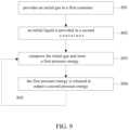
- An embodimentbased on the aforementioned heterogeneous pressure media and interactive actuation module, uses a single module or a combination of multiple single modules to determine the output pressure.
- An embodimentbased on the aforementioned heterogeneous pressure media and interactive actuation module, executes a first operation mode to store a first pressure energy and executes a second operation mode to convert the first pressure energy into a second pressure energy.
- An embodimentbased on the aforementioned heterogeneous pressure media and interactive actuation module, includes a hole cover and a repair pipe for repairers to repair a first container and a second container.
- An embodimentbased on the aforementioned heterogeneous pressure media and interactive actuation module, includes a pressure sensor to sense pressure.
- An embodimentbased on the aforementioned heterogeneous pressure media and interactive actuation module, includes a valve body with an open mode and a closed mode, whereby switching between the open mode and the closed mode, the first operation mode or the second operation mode is performed.
- the present disclosureuses substances that can be easily obtained from the environment, such as water, ambient air and other substances. Therefore, when the efficiency is reduced, the original energy storage and discharge efficiency can be restored simply by adding/refilling at least one of the initial gas, initial liquid, and working fluid, without the need to purchase natural gas, coal, and nuclear transformation. materials, etc.
- Residual power storage and conversionstores residual/unused power or backup power for emergency supplemental use, which is collectively referred to herein as residual electricity.
- the present disclosureuses residual power to drive pumps, so as to convert residual electricity into pressure energy by the heterogeneous pressure media and interactive actuation module to achieve the effect of storing residual electricity.
- the present disclosurecan instantly convert the pressure energy into electrical energy to make up for the insufficient electricity any time according to the increased demand of electricity.
- FIG. 2 Ais a schematic diagram illustrating the operation of the energy storage executing a first operation mode of FIG. 1 in accordance with some embodiments.
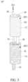
- FIG. 3is a three-dimensional schematic diagram of the energy storage in accordance with some embodiments.
- FIG. 5is a three-dimensional schematic diagram of the energy storage in accordance with some embodiments.
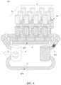
- FIG. 6is a three-dimensional schematic diagram of the energy storage system in accordance with some embodiments.
- FIG. 8is a three-dimensional schematic diagram of the energy storage system in accordance with some embodiments.
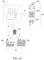
- FIG. 10is a schematic diagram illustrating the application of the energy storage system of FIG. 7 of a power network in accordance with some embodiments.
- the terms “include”, “comprise”, “have” or any other similar termsare intended to cover non-exclusive inclusions.
- an element, structure, product or device that contains a plurality of featuresis not limited to the requirements listed herein, but may include those features that are not explicitly listed but are generally inherent in the element, structure, product or device.
- the term “or”refers to the inclusive “or” rather than the exclusive “or”.
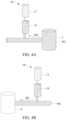
- the working fluid WLis injected into the energy storage 10 .
- the working fluid WLmay come from a liquid source.
- the liquid sourcemay be a water tank, a reservoir, a water tower, etc., which can serve as a device or equipment for storing the working fluid WL.
- the arrow illustrated in FIG. 2 Arepresents the flow path of the working fluid WL during the first operation mode M 1 .
- the working fluid WLis discharged from the energy storage 10 .
- the working fluid WLcan be discharged to the converter to drive the converter for operation and generating electricity.
- the arrow illustrated in FIG. 2 Billustrates the flow path of the working fluid WL during the second operation mode M 2 .
- the working fluid WLcan be water, in accordance with some embodiments.
- other fluids or liquidsare also within the scope of the present disclosure, such as organic solvents, inorganic solvents, molten salts, fluid ionic salts, supercritical fluids, and various gases or other flowable substances or pressure-generating substances and mechanisms, etc.
- the energy storage 10may be installed underground or enclosed by other materials (such as cement, concrete, etc.).
- the first container 12 and the second container 14when the first container 12 and the second container 14 are encapsulated by cement, the first container 12 and the second container 14 can increase the strength of resistance against pressure.
- the enclosure by cement or concretecan reduce the thickness/material requirements of the walls of the containers.
- an underground system of the present disclosurealso reduces the thickness/material requirements of the walls of the containers.
- the first container 12forms a first space SP 1 to store an initial gas IG.
- the first container 12is illustrated with a cylindrical tank body as an example.
- the first container 12may also be a polygonal tank body, a honeycomb-shaped tank body or another shaped-tank body.
- the initial gas IGcontains air, other fluids or gases, which are also within the scope of the embodiments, such as hydrogen, helium, nitrogen or mixed gases (such as 20% hydrogen and 80% helium), etc., as well as various gases or other flowable substances or substances and mechanisms that can generate pressure.
- the initial gas IGmay also be transformed from other material states.
- the gas stateis transformed from a solid-state or a liquid state. The foregoing transformation may occur, for example, through changes in temperature, pressure, etc.
- the initial gas IGmay not only stay in the first space SP 1 but may also appear in the second space SP 2 .
- the initial gas IGmay not fill the entire first space SP 1 .
- the initial gas IGin addition to filling the entire first space SP 1 , the initial gas IG may also fill a part of the first space SP 1 .
- the second container 14is disposed on one side of the first container 12 .
- the second container 14is disposed on the lower side of the first container 12 as an example. In other embodiments, the second container 14 may be disposed on either side the first container 12 ; that is, it is not limited to be disposed on the lower side of the first container 12 .
- the second container 14forms a second space SP 2 to store an initial liquid IL. After the second container 14 is connected to the first container 12 , the second space SP 2 connects with the first space SP 1 . In FIG.
- the working fluid WLis continuously injected into the second space SP 2 (as shown in FIG. 4 A ).
- the injected working fluid WLgradually increases the space occupied in the second space SP 2 by gradually increasing the volume in the second space SP 2 , thereby driving the initial liquid IL to continuously compress the initial gas IG in the first space SP 1 , until the initial gas IG in the first space SP 1 reaches a predetermined pressure, causing the first container 12 to reach and store a first pressure energy FPE (as illustrated in FIG. 3 ).
- the value of the predetermined pressurecan range from several kilopascals to several megapascals.
- the value of the predetermined pressuremay range from 4 megapascals (Mpa) (or N/m2) to 12 Mpa.
- Mpamegapascals
- the initial gas IGwill continue to be compressed until the initial liquid IL no longer pushes the initial gas IG due to pressure balance or the initial gas IG can no longer be compressed. It is then that the gas IG will stop being compressed.
- the pressure of the initial gas IGcan be reached or maintained at a predetermined pressure by adjusting the initial liquid IL to push the initial gas IG, thereby determining the amount of the first pressure energy FPE.
- the working fluid WLis discharged from the second space SP 2 toward the opposite direction (as shown in FIG. 4 B ).
- the initial fluid ILis pushed by the first pressure energy FPE, causing the working fluid WL to squeeze to move in the direction toward, for example, the converter 4 , which originates from the effect of pressure release caused by the continuous expansion of the compressed initial gas IG.
- the initial gas IGdrives the initial liquid IL to discharge, so as to convert the first pressure energy FPE into a second pressure energy SPE to drive the converter 4 .
- the converter 4is acted on by the second pressure energy SPE to generate electrical energy E (or electricity).
- FIG. 3is a three-dimensional schematic diagram of an energy storage 10 ′ in accordance with some embodiments.
- the energy storage 10 ′in addition to the first container 12 and the second container 14 described above, the energy storage 10 ′ further includes a first tube 16 and a second tube 18 .
- the arrangement of the first tube 16 and the second tube 18are more flexible.
- the first tube 16includes a first end 162 and a third end 164 .
- the first end 162is coupled to the first container 12 and the third end 164 is coupled to the second container 14 so that the first tube 16 communicates with the first space SP 1 and the second space SP 2 .
- first container 12the second container 14 , the first tube 16 , and the second tube 18 are provided above and will not be repeated here for the sake of brevity and clarity.
- the hole cover 29is disposed at the first container 12 . Opening the hole cover 29 connects the first space SP 1 with the outside space of the first container 12 . Closing the hole cover 29 blocks the connection between the first space SP 1 and the outside space of the first container 12 . Maintenance can be performed by a person (not shown in the figure) entering the first space SP 1 .
- the hole cover 29may further include a pressure safety valve (also called a pop-up valve) (not shown) used for selectively releasing gas or liquid to release pressure, so as to adjust the pressure safety valve so that the pressure of the first container 12 is maintained at a predetermined pressure setting the value of, for example, several megapascals and several megapascals.
- the maintenance pipe 30is disposed between the first container 12 and the second container 14 . Opening the maintenance pipe 30 connects the first space SP 1 and the second space SP 2 . Closing the maintenance pipe 30 blocks the connection between the first space SP 1 and the second space SP 2 . A maintenance person (not shown in figure) is allowed to enter the second space SP 2 for maintenance.
- the maintenance pipeline 30may further include a pressure safety valve (also called a pop-up valve) (not shown) used for selectively releasing gas or liquid to release the pressure, so as to be able to adjust the pressure to reach a predetermined pressure setting value.
- each of the energy storages 102 , 104 , 106 and 108respectively includes a one to one correspondence of first container 12 to a second container 14 , a first tube 16 and a second tube 18 .
- Each first container 12forms a first space SP 1 to store an initial gas IG.
- Each second container 14is disposed on the lower side of a first container 12 , and the respective second container 14 forms a second space SP 2 to store an initial liquid IL.
- each second tube 18is coupled to a second container 14 and the other end of the second tube 18 is coupled to the first pipe 6 .
- the diameter of the second tube 18may be larger or smaller than the diameter of the first tube 16 .
- the liquid source 2supplies and recycles the working liquid WL.
- the liquid source 2may be a reservoir, a water tower, a reservoir, and the like.
- the description of the function of the liquid source 2 functioning as a supplyis provided above will not be repeated here for the sake of brevity and clarity.
- the liquid source 2can also recycle the working fluid WL outputted by the converter 4 through the second pipe 8 .
- the converter 4receives and outputs the working fluid WL.
- the converter 4may be a liquid pump, a turbo pump, a liquid generator, a liquid turbine generator, a hydro turbine generator, or other liquid driven device configured to generate electricity.
- the converter 4can function as a supply, reference may be made to the description of the prior embodiment, which will not be repeated here.
- the liquid source 2can also recycle the working liquid WL outputted from the converter 4 through the second pipe 8 .
- the working liquid WL from the liquid source 2is injected into the second spaces SP 2 through the first pipe 6 and the second tubes 18 , so that the working liquid WL drives the initial liquid IL through the first tubes 16 to continuously compresses the initial gas IG in the first spaces SP 1 until the initial gas IG acting on the first spaces SP 1 have a predetermined pressure, thereby enabling the first containers 12 to store a first pressure energy FPE.
- the initial gas IGcontinuously expands to drive the initial liquid IL moving toward and discharge from the second tubes 18 to convert the first pressure energy FPE into a second pressure energy SPE and pass through the first pipes 6 to drive the converter 4 to generate an electrical energy E.
- the working liquid WLafter driving the converter 4 , returns to the liquid source 2 through the second pipe 8 .
- FIG. 7is a three-dimensional schematic diagram of an energy storage system 20 ′ in accordance with some embodiments.
- the energy storage system 20 ′includes not only the energy storage 10 ′′, the liquid source 2 , the converter 4 , the first pipe 6 and the second pipe 8 , but the energy storage system 20 ′ also includes at least one pressure sensor 32 , a pump 34 , valve bodies 36 , 36 ′, and a controller 38 .
- the controller 38can be implemented on a server computer, which broadly represents one or more computers, such as one or more desktop computers, server computers, a server farm, a cloud computing platform, a parallel computer, virtual computing instances in public or private datacenters, and/or instances of a server-based application.
- the pump 34enables the heterogeneous pressure media and interactive actuation energy storage system to have a better energy storage effect, storing and releasing more energy.
- the pump 34may instead be disposed at at least one of the first spaces SP 1 , the second spaces SP 2 , the first tubes 16 , the second tubes 18 , between the first tubes 16 and the first containers 12 , between the second tubes 18 and the second containers 14 , the first pipe 6 , the second pipe 8 , between the second pipe 8 and the liquid source 2 , and between the second pipe 8 and the converter 2 .
- the pump 34regulates the working liquid WL of the liquid source 2 to enter the energy storage 10 ′′.
- the energy storage 10 ′′further includes an extended energy storage unit 40 connected to the converter 4 to store electrical energy E.
- the extended energy storage unit 40may be, for example, a storage battery, a secondary battery, a supercapacitor, or the like.
- the energy storage system 20 ′′can contain n ⁇ m energy storages 10 ′′, as shown in FIG. 8 , which is a three-dimensional schematic diagram of the energy storage system 20 ′′ in accordance with some embodiments.
- the devices and systemsare used to store and release energy so that such stored energy can be used on-demand.
- a systemconverts an electrical energy into a potential energy or compressed air energy, storing the converted energy, and releasing the stored energy when in-demand.
Landscapes
- Engineering & Computer Science (AREA)
- Power Engineering (AREA)
- Physics & Mathematics (AREA)
- General Physics & Mathematics (AREA)
- Automation & Control Theory (AREA)
- Filling Or Discharging Of Gas Storage Vessels (AREA)
Abstract
Description
Claims (28)
Priority Applications (1)
| Application Number | Priority Date | Filing Date | Title |
|---|---|---|---|
| US17/892,676US12355238B2 (en) | 2021-12-03 | 2022-08-22 | Energy storage systems and methods using heterogeneous pressure media and interactive actuation module |
Applications Claiming Priority (8)
| Application Number | Priority Date | Filing Date | Title |
|---|---|---|---|
| CN202111466565.5ACN116291792B (en) | 2021-12-03 | 2021-12-03 | Energy storage system using heterogeneous pressure energy interactive actuating module and method thereof |
| CN202111466565.5 | 2021-12-03 | ||
| US17/777,516US11870253B2 (en) | 2021-12-03 | 2022-05-16 | Energy storage systems and methods using heterogeneous pressure media and interactive actuation module |
| PCT/US2022/029374WO2023101718A1 (en) | 2021-12-03 | 2022-05-16 | Energy storage systems and methods using heterogeneous pressure media and interactive actuation module |
| US202263345269P | 2022-05-24 | 2022-05-24 | |
| US202263345274P | 2022-05-24 | 2022-05-24 | |
| US202263349284P | 2022-06-06 | 2022-06-06 | |
| US17/892,676US12355238B2 (en) | 2021-12-03 | 2022-08-22 | Energy storage systems and methods using heterogeneous pressure media and interactive actuation module |
Related Parent Applications (2)
| Application Number | Title | Priority Date | Filing Date |
|---|---|---|---|
| US17/777,516Continuation-In-PartUS11870253B2 (en) | 2021-12-03 | 2022-05-16 | Energy storage systems and methods using heterogeneous pressure media and interactive actuation module |
| PCT/US2022/029374Continuation-In-PartWO2023101718A1 (en) | 2021-12-03 | 2022-05-16 | Energy storage systems and methods using heterogeneous pressure media and interactive actuation module |
Publications (2)
| Publication Number | Publication Date |
|---|---|
| US20230179017A1 US20230179017A1 (en) | 2023-06-08 |
| US12355238B2true US12355238B2 (en) | 2025-07-08 |
Family
ID=86609200
Family Applications (1)
| Application Number | Title | Priority Date | Filing Date |
|---|---|---|---|
| US17/892,676ActiveUS12355238B2 (en) | 2021-12-03 | 2022-08-22 | Energy storage systems and methods using heterogeneous pressure media and interactive actuation module |
Country Status (1)
| Country | Link |
|---|---|
| US (1) | US12355238B2 (en) |
Citations (111)
| Publication number | Priority date | Publication date | Assignee | Title |
|---|---|---|---|---|
| US2652690A (en)* | 1951-09-27 | 1953-09-22 | Minnie O Brien Labriola | Utility master power unit |
| US3991574A (en) | 1975-02-03 | 1976-11-16 | Frazier Larry Vane W | Fluid pressure power plant with double-acting piston |
| US4206608A (en)* | 1978-06-21 | 1980-06-10 | Bell Thomas J | Natural energy conversion, storage and electricity generation system |
| US4220006A (en) | 1978-11-20 | 1980-09-02 | Kindt Robert J | Power generator |
| US4367786A (en) | 1979-11-23 | 1983-01-11 | Daimler-Benz Aktiengesellschaft | Hydrostatic bladder-type storage means |
| US4525631A (en) | 1981-12-30 | 1985-06-25 | Allison John H | Pressure energy storage device |
| JPH0617555A (en) | 1992-06-30 | 1994-01-25 | Nippon Steel Corp | Underground tank for compressed gas storage |
| US6109358A (en)* | 1999-02-05 | 2000-08-29 | Conor Pacific Environmental Technologies Inc. | Venting apparatus and method for remediation of a porous medium |
| US20020144503A1 (en) | 2001-04-10 | 2002-10-10 | Merswolke Paul H.F. | Wind powered hydroelectric power plant and method of operation thereof |
| US6718761B2 (en)* | 2001-04-10 | 2004-04-13 | New World Generation Inc. | Wind powered hydroelectric power plant and method of operation thereof |
| US20050155347A1 (en) | 2002-03-27 | 2005-07-21 | Lewellin Richard L. | Engine for converting thermal energy to stored energy |
| US20050198959A1 (en) | 2004-03-15 | 2005-09-15 | Frank Schubert | Electric generation facility and method employing solar technology |
| US20050279085A1 (en)* | 2004-06-18 | 2005-12-22 | Moore George V | Energy conversion system |
| US7168252B1 (en) | 2005-12-19 | 2007-01-30 | Price David E | Solar heated generator |
| US7281371B1 (en)* | 2006-08-23 | 2007-10-16 | Ebo Group, Inc. | Compressed air pumped hydro energy storage and distribution system |
| US20070289622A1 (en) | 2006-06-19 | 2007-12-20 | Lockheed Martin Corporation | Integrated solar energy conversion system, method, and apparatus |
| US7364810B2 (en) | 2003-09-03 | 2008-04-29 | Bloom Energy Corporation | Combined energy storage and fuel generation with reversible fuel cells |
| US20080136186A1 (en) | 2006-11-29 | 2008-06-12 | Yshape Inc. | Hydraulic energy accumulator |
| US20080211230A1 (en) | 2005-07-25 | 2008-09-04 | Rexorce Thermionics, Inc. | Hybrid power generation and energy storage system |
| US20090152871A1 (en)* | 2007-12-14 | 2009-06-18 | Jose Ong Ching | Multiple energy inputs hydropower system |
| US7579700B1 (en)* | 2008-05-28 | 2009-08-25 | Moshe Meller | System and method for converting electrical energy into pressurized air and converting pressurized air into electricity |
| US7663255B2 (en)* | 2006-08-21 | 2010-02-16 | Korea Institute Of Machinery & Materials | Compressed-air-storing electricity generating system and electricity generating method using the same |
| TWM375775U (en) | 2008-07-22 | 2010-03-11 | Hong-Wei Zhang | Fluid energy conversion device |
| US20100089063A1 (en) | 2008-04-09 | 2010-04-15 | Sustainx, Inc. | Systems and Methods for Energy Storage and Recovery Using Rapid Isothermal Gas Expansion and Compression |
| US20100096858A1 (en) | 2007-09-27 | 2010-04-22 | William Riley | Hydroelectric pumped-storage |
| US7743609B1 (en) | 2008-02-06 | 2010-06-29 | Florida Turbine Technologies, Inc. | Power plant with energy storage deep water tank |
| US20100192568A1 (en) | 2009-02-05 | 2010-08-05 | Grant Peacock | Phase change compressor |
| US20100205960A1 (en) | 2009-01-20 | 2010-08-19 | Sustainx, Inc. | Systems and Methods for Combined Thermal and Compressed Gas Energy Conversion Systems |
| US20100252028A1 (en) | 2009-03-26 | 2010-10-07 | Robert Charles Mierisch | Intermediate pressure storage system for thermal storage |
| US20100270801A1 (en) | 2009-04-28 | 2010-10-28 | Liu Kuo-Shen | Electricity storage and recovery system |
| US20100326062A1 (en) | 2009-06-29 | 2010-12-30 | Lightsail Energy Inc. | Compressed air energy storage system utilizing two-phase flow to facilitate heat exchange |
| US7878280B2 (en) | 2003-04-09 | 2011-02-01 | Bloom Energy Corporation | Low pressure hydrogen fueled vehicle and method of operating same |
| US20110030361A1 (en)* | 2009-08-06 | 2011-02-10 | Newwindtech Llc | Hydrostatic linear wind mill for wind energy harnessing applications |
| WO2011024928A1 (en) | 2009-08-24 | 2011-03-03 | Kawanishi Eiji | Hybrid power generator coupled to gravity power generator using balance which has pressure load device |
| US20110120673A1 (en) | 2009-09-17 | 2011-05-26 | Xiaodong Xiang | Systems and methods of thermal transfer and/or storage |
| WO2011076926A2 (en) | 2009-12-23 | 2011-06-30 | Global Power And Energy Limited | Compressed air energy storage system |
| US8037678B2 (en) | 2009-09-11 | 2011-10-18 | Sustainx, Inc. | Energy storage and generation systems and methods using coupled cylinder assemblies |
| US20110259007A1 (en) | 2009-06-05 | 2011-10-27 | Mitsubishi Heavy Industries, Ltd. | Concentrated solar power gas turbine and concentrated-solar-power-gas turbine power generation equipment |
| US20110266804A1 (en)* | 2010-05-03 | 2011-11-03 | Joseph Dolcimascolo | Ancient hydroelectric company |
| US20110296822A1 (en) | 2010-04-08 | 2011-12-08 | Benjamin Bollinger | Efficiency of liquid heat exchange in compressed-gas energy storage systems |
| US8127542B1 (en)* | 2011-04-13 | 2012-03-06 | Joseph Dolcimascolo | Portable hydroelectric generating system |
| US8240956B2 (en) | 2010-04-15 | 2012-08-14 | Eydrostor Inc. | System and method for modularly deployable and scalable compressed air energy accumulator |
| TW201241308A (en) | 2011-04-15 | 2012-10-16 | Univ Nat Central | Phase change thermal storage heat power generation system |
| TWM440345U (en) | 2012-07-13 | 2012-11-01 | Huan-Lin Zeng | Power generating device |
| US20120305411A1 (en) | 2010-02-15 | 2012-12-06 | Ron Elazari-Volcani | Underwater energy storage system and power station powered therewith |
| TWM446825U (en) | 2012-04-06 | 2013-02-11 | zhe-yang Li | Structure improvement for energy storage of fluid compressed by piston |
| CN102966387A (en) | 2012-11-14 | 2013-03-13 | 北京修齐四方科技有限公司 | Method for generating power by using stored potential energy |
| US20130134612A1 (en) | 2011-11-24 | 2013-05-30 | Cameron Phillip Lewis | System and method for fragmentation and dispersal of a compressed gas body |
| US20130214537A1 (en) | 2010-11-30 | 2013-08-22 | Mitsubishi Heavy Industries, Ltd | Power generating apparatus of renewable energy type and operation method thereof |
| US20130219892A1 (en) | 2012-02-27 | 2013-08-29 | Energy Compression Inc. | Modular adsorption-enhanced compressed air energy storage system with regenerative thermal energy recycling |
| US20130220310A1 (en) | 2010-10-25 | 2013-08-29 | Christian Thomas Gregory | Solar thermal receiver with concentric tube modules |
| US20140026547A1 (en) | 2012-07-27 | 2014-01-30 | Samsung Techwin Co., Ltd. | Energy storage system and method for storing energy and recovering the stored energy using the system |
| US8723347B2 (en) | 2010-03-24 | 2014-05-13 | Lightsail Energy, Inc. | Energy storage system utilizing compressed gas |
| US8739533B2 (en) | 2010-12-02 | 2014-06-03 | Or Yogev | Solar augmented wind turbine for stable and dispatchable utility scale power generation |
| CN103925111A (en) | 2014-04-30 | 2014-07-16 | 郭远军 | Parallel motion high-low-pressure power machine and application thereof |
| US8806866B2 (en) | 2011-05-17 | 2014-08-19 | Sustainx, Inc. | Systems and methods for efficient two-phase heat transfer in compressed-air energy storage systems |
| US8823195B2 (en)* | 2012-04-03 | 2014-09-02 | Mark Robert John LEGACY | Hydro electric energy generation and storage structure |
| US20150000248A1 (en) | 2012-02-23 | 2015-01-01 | Prextor Systems, S.L. | Combined Cycle CAES Technology (CCC) |
| US9059605B2 (en) | 2010-09-10 | 2015-06-16 | Saben Murray | Energy storage devices and methods of using same |
| US20150211551A1 (en) | 2014-01-29 | 2015-07-30 | Curtis VanWalleghem | Energy accumulation apparatus |
| JP2015145674A (en) | 2006-09-05 | 2015-08-13 | エムディーアイ−モーター・ディベロップメント・インターナショナル・エス.エー. | Compressed-air or gas and/or additional-energy engine having active expansion chamber |
| WO2015159278A1 (en) | 2014-04-13 | 2015-10-22 | Yuval Broshy | System and method for high capacity energy storage with two fluids |
| CN103216426B (en) | 2013-02-22 | 2016-02-10 | 中国科学院理化技术研究所 | Regenerative compressed air energy storage system |
| US9261068B2 (en)* | 2013-01-16 | 2016-02-16 | Yaser K. Barakat | Hydroelectric power generating system |
| US20160178129A1 (en) | 2006-02-27 | 2016-06-23 | Highview Enterprises Limited | Method of Storing Energy and a Cryogenic Energy Storage System |
| US20160201658A1 (en) | 2013-08-30 | 2016-07-14 | Heliix, Inc. | Thermal compressor |
| US9410559B2 (en) | 2014-01-29 | 2016-08-09 | Hydrostor, Inc. | Energy-accumulation apparatus |
| CN106091403A (en) | 2016-06-16 | 2016-11-09 | 无锡市翱宇特新科技发展有限公司 | A kind of photo-thermal photovoltaic electric power water heater |
| US20160348637A1 (en) | 2013-09-25 | 2016-12-01 | Emil Bächli Energietechnik Ag | Method and system for combined pump water pressure-compressed air energy storage at constant turbine water pressure |
| CN105043147B (en) | 2015-06-25 | 2017-01-25 | 中国科学院理化技术研究所 | Liquefied compressed air energy storage system adopting liquid cold accumulation working medium |
| US9562521B2 (en) | 2012-04-24 | 2017-02-07 | Or Yogev | Hybrid system for electric power generation from solar-thermal energy and wind energy sources |
| CN102797613B (en) | 2011-05-25 | 2017-03-01 | 中国科学院工程热物理研究所 | A kind of water pumping compressed air energy-storage |
| CN107002641A (en) | 2014-09-29 | 2017-08-01 | 西门子公司 | Apparatus and method for storage energy |
| US9797366B2 (en) | 2011-11-11 | 2017-10-24 | Roentdek-Handels | Pumped-storage power plant |
| CN104675680B (en) | 2014-12-16 | 2017-12-15 | 西安交通大学 | A kind of compressed-air energy-storage system of supply of cooling, heating and electrical powers |
| CN106677848B (en) | 2016-12-29 | 2018-03-02 | 西安交通大学 | A kind of joint energy-storage system and method using air and water as energy storage working medium |
| CN106499612B (en) | 2016-12-01 | 2018-06-26 | 西安交通大学 | Compressed air double-energy storage system without external heat source |
| US20180306066A1 (en) | 2015-10-20 | 2018-10-25 | Niki Enerji Uretim A.S. | A power generator and a method of generating power |
| US20180320679A1 (en) | 2017-05-02 | 2018-11-08 | EnisEnerGen, LLC | Green Communities |
| US20190003384A1 (en) | 2013-04-03 | 2019-01-03 | Sigma Energy Storage Inc. | Compressed air energy storage and recovery |
| US10203735B2 (en) | 2012-03-21 | 2019-02-12 | Bloom Energy Corporation | Systems and methods for providing fuel cell power to a data center |
| US10205323B2 (en)* | 2014-11-21 | 2019-02-12 | James Arthur Lowell | Hydroelectricity and compressed-air power converter system |
| US20190052094A1 (en) | 2017-08-10 | 2019-02-14 | Bloom Energy Corporation | Methods of advanced grid and microgrid support functionalities through hybrid fuel cell systems |
| US10208737B1 (en) | 2011-10-25 | 2019-02-19 | Walter B. Freeman | Uniformly pressurized thermal energy recovery systems |
| US20190064757A1 (en) | 2017-08-31 | 2019-02-28 | Energy Harbors Corporation, Inc. | Energy management with multiple pressurized storage elements |
| CN109826741A (en) | 2019-02-20 | 2019-05-31 | 西安交通大学 | A damless pumped storage system and method for variable working conditions using an abandoned tunnel or an air-raid shelter as an energy storage container |
| US10344741B2 (en)* | 2015-02-12 | 2019-07-09 | University Of Malta | Hydro-pneumatic energy storage system |
| US20190221697A1 (en) | 2016-09-02 | 2019-07-18 | Hans Se-young Cho | System for power generation using solar energy |
| US10415469B2 (en)* | 2017-08-25 | 2019-09-17 | Savannah River Nuclear Solutions, Llc | Hybrid compressed air/water energy storage system and method |
| CN108571415B (en) | 2018-04-03 | 2019-12-24 | 西安交通大学 | A high-pressure adiabatic gas storage pumped compressed air energy storage system |
| US10655505B2 (en) | 2015-05-08 | 2020-05-19 | Kabushiki Kaisha Kobe Seiko Sho (Kobe Steel, Ltd.) | Compressed air energy storage and power generation device and compressed air energy storage and power generation method |
| US10707802B1 (en)* | 2017-03-13 | 2020-07-07 | AquaEnergy, LLC | Pressurized pumped hydro storage system |
| US20200263830A1 (en) | 2017-03-09 | 2020-08-20 | Hydrostor Inc. | A Thermal Storage Apparatus for a Compressed Gas Energy Storage System |
| CN111636991A (en) | 2020-05-13 | 2020-09-08 | 深圳新效能科技有限公司 | Device for driving hydraulic generator by air-water mixed impulsive force |
| US10823132B2 (en) | 2016-10-10 | 2020-11-03 | Jeshoa MESINGER | Hydraulic-pneumatic energy storage and recovery system |
| US10836579B2 (en) | 2016-11-16 | 2020-11-17 | Augwind, Ltd. | System for storing compressed gas and method for construction thereof |
| US10837429B2 (en) | 2018-07-19 | 2020-11-17 | Energy Vault, Inc. | Energy storage system and method |
| US10859207B2 (en) | 2017-02-01 | 2020-12-08 | Hydrostor Inc. | Hydrostatically compensated compressed gas energy storage system |
| CN112360584A (en) | 2020-11-11 | 2021-02-12 | 深圳新效能科技有限公司 | Application method of waste heat recycling efficient hydroelectric generating set |
| TW202108950A (en) | 2019-08-30 | 2021-03-01 | 黃仲廷 | Heat pump enhanced concentrated solar power generation system capable of improving kinetic energy of the engine outputting water vapor to increase the torque |
| CN112459980A (en) | 2019-09-08 | 2021-03-09 | 奥格温德有限公司 | System for energy storage and power generation |
| US20210071632A1 (en) | 2018-03-23 | 2021-03-11 | Hans Gude Gudesen | Underwater energy storage system |
| WO2021078568A1 (en) | 2019-10-24 | 2021-04-29 | IFP Energies Nouvelles | Tank for storing energy in the form of pressurized gas, made of ultra high performance fibre-reinforced concrete |
| US20210206574A1 (en) | 2018-06-20 | 2021-07-08 | Augwind Ltd. | System for storing compressed fluid |
| US20210221652A1 (en) | 2020-01-22 | 2021-07-22 | Energy Vault, Inc. | Damped self-centering mechanism |
| US20210351615A1 (en) | 2019-09-08 | 2021-11-11 | Augwind Ltd. | System for energy storage and electrical power generation |
| US20210388810A1 (en) | 2019-02-27 | 2021-12-16 | Hydrostor Inc. | Hydrostatically compensated caes system having an elevated compensation liquid reservoir |
| US20210404446A1 (en) | 2020-06-30 | 2021-12-30 | Energy Vault, Inc. | Energy storage and delivery system |
| CN114198242A (en) | 2021-12-06 | 2022-03-18 | 西安交通大学 | A pumped-storage system and method utilizing spring elastic potential energy |
| US20220090585A1 (en) | 2019-01-15 | 2022-03-24 | Hydrostor Inc. | Compressed gas energy storage system |
| US20220243701A1 (en) | 2021-02-02 | 2022-08-04 | Energy Vault, Inc. | Energy storage system with elevator lift system |
- 2022
- 2022-08-22USUS17/892,676patent/US12355238B2/enactiveActive
Patent Citations (119)
| Publication number | Priority date | Publication date | Assignee | Title |
|---|---|---|---|---|
| US2652690A (en)* | 1951-09-27 | 1953-09-22 | Minnie O Brien Labriola | Utility master power unit |
| US3991574A (en) | 1975-02-03 | 1976-11-16 | Frazier Larry Vane W | Fluid pressure power plant with double-acting piston |
| US4206608A (en)* | 1978-06-21 | 1980-06-10 | Bell Thomas J | Natural energy conversion, storage and electricity generation system |
| US4220006A (en) | 1978-11-20 | 1980-09-02 | Kindt Robert J | Power generator |
| US4367786A (en) | 1979-11-23 | 1983-01-11 | Daimler-Benz Aktiengesellschaft | Hydrostatic bladder-type storage means |
| US4525631A (en) | 1981-12-30 | 1985-06-25 | Allison John H | Pressure energy storage device |
| JPH0617555A (en) | 1992-06-30 | 1994-01-25 | Nippon Steel Corp | Underground tank for compressed gas storage |
| US6109358A (en)* | 1999-02-05 | 2000-08-29 | Conor Pacific Environmental Technologies Inc. | Venting apparatus and method for remediation of a porous medium |
| US20020144503A1 (en) | 2001-04-10 | 2002-10-10 | Merswolke Paul H.F. | Wind powered hydroelectric power plant and method of operation thereof |
| US6718761B2 (en)* | 2001-04-10 | 2004-04-13 | New World Generation Inc. | Wind powered hydroelectric power plant and method of operation thereof |
| US20050155347A1 (en) | 2002-03-27 | 2005-07-21 | Lewellin Richard L. | Engine for converting thermal energy to stored energy |
| US7878280B2 (en) | 2003-04-09 | 2011-02-01 | Bloom Energy Corporation | Low pressure hydrogen fueled vehicle and method of operating same |
| US7364810B2 (en) | 2003-09-03 | 2008-04-29 | Bloom Energy Corporation | Combined energy storage and fuel generation with reversible fuel cells |
| US20050198959A1 (en) | 2004-03-15 | 2005-09-15 | Frank Schubert | Electric generation facility and method employing solar technology |
| US20050279085A1 (en)* | 2004-06-18 | 2005-12-22 | Moore George V | Energy conversion system |
| US20080211230A1 (en) | 2005-07-25 | 2008-09-04 | Rexorce Thermionics, Inc. | Hybrid power generation and energy storage system |
| US7168252B1 (en) | 2005-12-19 | 2007-01-30 | Price David E | Solar heated generator |
| US20160178129A1 (en) | 2006-02-27 | 2016-06-23 | Highview Enterprises Limited | Method of Storing Energy and a Cryogenic Energy Storage System |
| US20070289622A1 (en) | 2006-06-19 | 2007-12-20 | Lockheed Martin Corporation | Integrated solar energy conversion system, method, and apparatus |
| US7663255B2 (en)* | 2006-08-21 | 2010-02-16 | Korea Institute Of Machinery & Materials | Compressed-air-storing electricity generating system and electricity generating method using the same |
| US7281371B1 (en)* | 2006-08-23 | 2007-10-16 | Ebo Group, Inc. | Compressed air pumped hydro energy storage and distribution system |
| JP2015145674A (en) | 2006-09-05 | 2015-08-13 | エムディーアイ−モーター・ディベロップメント・インターナショナル・エス.エー. | Compressed-air or gas and/or additional-energy engine having active expansion chamber |
| US20080136186A1 (en) | 2006-11-29 | 2008-06-12 | Yshape Inc. | Hydraulic energy accumulator |
| US20110041490A1 (en) | 2006-11-29 | 2011-02-24 | YSHAPE, Inc. | Hydraulic energy accumulator |
| US20100096858A1 (en) | 2007-09-27 | 2010-04-22 | William Riley | Hydroelectric pumped-storage |
| US20090152871A1 (en)* | 2007-12-14 | 2009-06-18 | Jose Ong Ching | Multiple energy inputs hydropower system |
| US7743609B1 (en) | 2008-02-06 | 2010-06-29 | Florida Turbine Technologies, Inc. | Power plant with energy storage deep water tank |
| US20100089063A1 (en) | 2008-04-09 | 2010-04-15 | Sustainx, Inc. | Systems and Methods for Energy Storage and Recovery Using Rapid Isothermal Gas Expansion and Compression |
| US7579700B1 (en)* | 2008-05-28 | 2009-08-25 | Moshe Meller | System and method for converting electrical energy into pressurized air and converting pressurized air into electricity |
| TWM375775U (en) | 2008-07-22 | 2010-03-11 | Hong-Wei Zhang | Fluid energy conversion device |
| US20100205960A1 (en) | 2009-01-20 | 2010-08-19 | Sustainx, Inc. | Systems and Methods for Combined Thermal and Compressed Gas Energy Conversion Systems |
| US20100192568A1 (en) | 2009-02-05 | 2010-08-05 | Grant Peacock | Phase change compressor |
| US20100252028A1 (en) | 2009-03-26 | 2010-10-07 | Robert Charles Mierisch | Intermediate pressure storage system for thermal storage |
| US20100270801A1 (en) | 2009-04-28 | 2010-10-28 | Liu Kuo-Shen | Electricity storage and recovery system |
| US20110259007A1 (en) | 2009-06-05 | 2011-10-27 | Mitsubishi Heavy Industries, Ltd. | Concentrated solar power gas turbine and concentrated-solar-power-gas turbine power generation equipment |
| US9444378B2 (en)* | 2009-06-29 | 2016-09-13 | Lightsail Energy, Inc. | Compressed air energy storage system utilizing two-phase flow to facilitate heat exchange |
| US20100326062A1 (en) | 2009-06-29 | 2010-12-30 | Lightsail Energy Inc. | Compressed air energy storage system utilizing two-phase flow to facilitate heat exchange |
| US20110030361A1 (en)* | 2009-08-06 | 2011-02-10 | Newwindtech Llc | Hydrostatic linear wind mill for wind energy harnessing applications |
| WO2011024928A1 (en) | 2009-08-24 | 2011-03-03 | Kawanishi Eiji | Hybrid power generator coupled to gravity power generator using balance which has pressure load device |
| US8037678B2 (en) | 2009-09-11 | 2011-10-18 | Sustainx, Inc. | Energy storage and generation systems and methods using coupled cylinder assemblies |
| US20110120673A1 (en) | 2009-09-17 | 2011-05-26 | Xiaodong Xiang | Systems and methods of thermal transfer and/or storage |
| WO2011076926A2 (en) | 2009-12-23 | 2011-06-30 | Global Power And Energy Limited | Compressed air energy storage system |
| US20120305411A1 (en) | 2010-02-15 | 2012-12-06 | Ron Elazari-Volcani | Underwater energy storage system and power station powered therewith |
| US8723347B2 (en) | 2010-03-24 | 2014-05-13 | Lightsail Energy, Inc. | Energy storage system utilizing compressed gas |
| US20110296822A1 (en) | 2010-04-08 | 2011-12-08 | Benjamin Bollinger | Efficiency of liquid heat exchange in compressed-gas energy storage systems |
| US8240956B2 (en) | 2010-04-15 | 2012-08-14 | Eydrostor Inc. | System and method for modularly deployable and scalable compressed air energy accumulator |
| US20110266804A1 (en)* | 2010-05-03 | 2011-11-03 | Joseph Dolcimascolo | Ancient hydroelectric company |
| US9059605B2 (en) | 2010-09-10 | 2015-06-16 | Saben Murray | Energy storage devices and methods of using same |
| US20130220310A1 (en) | 2010-10-25 | 2013-08-29 | Christian Thomas Gregory | Solar thermal receiver with concentric tube modules |
| US20130214537A1 (en) | 2010-11-30 | 2013-08-22 | Mitsubishi Heavy Industries, Ltd | Power generating apparatus of renewable energy type and operation method thereof |
| US8739533B2 (en) | 2010-12-02 | 2014-06-03 | Or Yogev | Solar augmented wind turbine for stable and dispatchable utility scale power generation |
| US8127542B1 (en)* | 2011-04-13 | 2012-03-06 | Joseph Dolcimascolo | Portable hydroelectric generating system |
| TW201241308A (en) | 2011-04-15 | 2012-10-16 | Univ Nat Central | Phase change thermal storage heat power generation system |
| US8806866B2 (en) | 2011-05-17 | 2014-08-19 | Sustainx, Inc. | Systems and methods for efficient two-phase heat transfer in compressed-air energy storage systems |
| CN102797613B (en) | 2011-05-25 | 2017-03-01 | 中国科学院工程热物理研究所 | A kind of water pumping compressed air energy-storage |
| US10208737B1 (en) | 2011-10-25 | 2019-02-19 | Walter B. Freeman | Uniformly pressurized thermal energy recovery systems |
| US9797366B2 (en) | 2011-11-11 | 2017-10-24 | Roentdek-Handels | Pumped-storage power plant |
| US20130134612A1 (en) | 2011-11-24 | 2013-05-30 | Cameron Phillip Lewis | System and method for fragmentation and dispersal of a compressed gas body |
| US20150000248A1 (en) | 2012-02-23 | 2015-01-01 | Prextor Systems, S.L. | Combined Cycle CAES Technology (CCC) |
| US20130219892A1 (en) | 2012-02-27 | 2013-08-29 | Energy Compression Inc. | Modular adsorption-enhanced compressed air energy storage system with regenerative thermal energy recycling |
| US10203735B2 (en) | 2012-03-21 | 2019-02-12 | Bloom Energy Corporation | Systems and methods for providing fuel cell power to a data center |
| US8823195B2 (en)* | 2012-04-03 | 2014-09-02 | Mark Robert John LEGACY | Hydro electric energy generation and storage structure |
| TWM446825U (en) | 2012-04-06 | 2013-02-11 | zhe-yang Li | Structure improvement for energy storage of fluid compressed by piston |
| US9562521B2 (en) | 2012-04-24 | 2017-02-07 | Or Yogev | Hybrid system for electric power generation from solar-thermal energy and wind energy sources |
| TWM440345U (en) | 2012-07-13 | 2012-11-01 | Huan-Lin Zeng | Power generating device |
| US9422948B2 (en)* | 2012-07-27 | 2016-08-23 | Hanwha Techwin Co., Ltd. | Energy storage system and method for storing energy and recovering the stored energy using the system |
| US20140026547A1 (en) | 2012-07-27 | 2014-01-30 | Samsung Techwin Co., Ltd. | Energy storage system and method for storing energy and recovering the stored energy using the system |
| CN102966387A (en) | 2012-11-14 | 2013-03-13 | 北京修齐四方科技有限公司 | Method for generating power by using stored potential energy |
| US9261068B2 (en)* | 2013-01-16 | 2016-02-16 | Yaser K. Barakat | Hydroelectric power generating system |
| CN103216426B (en) | 2013-02-22 | 2016-02-10 | 中国科学院理化技术研究所 | Regenerative compressed air energy storage system |
| US20190003384A1 (en) | 2013-04-03 | 2019-01-03 | Sigma Energy Storage Inc. | Compressed air energy storage and recovery |
| US20160201658A1 (en) | 2013-08-30 | 2016-07-14 | Heliix, Inc. | Thermal compressor |
| US20160348637A1 (en) | 2013-09-25 | 2016-12-01 | Emil Bächli Energietechnik Ag | Method and system for combined pump water pressure-compressed air energy storage at constant turbine water pressure |
| US9410559B2 (en) | 2014-01-29 | 2016-08-09 | Hydrostor, Inc. | Energy-accumulation apparatus |
| US20150211551A1 (en) | 2014-01-29 | 2015-07-30 | Curtis VanWalleghem | Energy accumulation apparatus |
| WO2015159278A1 (en) | 2014-04-13 | 2015-10-22 | Yuval Broshy | System and method for high capacity energy storage with two fluids |
| CN103925111A (en) | 2014-04-30 | 2014-07-16 | 郭远军 | Parallel motion high-low-pressure power machine and application thereof |
| US20170264164A1 (en) | 2014-09-29 | 2017-09-14 | Siemens Aktiengesellschaft | Device and Method for Storing Energy |
| CN107002641A (en) | 2014-09-29 | 2017-08-01 | 西门子公司 | Apparatus and method for storage energy |
| US10205323B2 (en)* | 2014-11-21 | 2019-02-12 | James Arthur Lowell | Hydroelectricity and compressed-air power converter system |
| CN104675680B (en) | 2014-12-16 | 2017-12-15 | 西安交通大学 | A kind of compressed-air energy-storage system of supply of cooling, heating and electrical powers |
| US10344741B2 (en)* | 2015-02-12 | 2019-07-09 | University Of Malta | Hydro-pneumatic energy storage system |
| US10655505B2 (en) | 2015-05-08 | 2020-05-19 | Kabushiki Kaisha Kobe Seiko Sho (Kobe Steel, Ltd.) | Compressed air energy storage and power generation device and compressed air energy storage and power generation method |
| CN105043147B (en) | 2015-06-25 | 2017-01-25 | 中国科学院理化技术研究所 | Liquefied compressed air energy storage system adopting liquid cold accumulation working medium |
| US20180306066A1 (en) | 2015-10-20 | 2018-10-25 | Niki Enerji Uretim A.S. | A power generator and a method of generating power |
| CN106091403A (en) | 2016-06-16 | 2016-11-09 | 无锡市翱宇特新科技发展有限公司 | A kind of photo-thermal photovoltaic electric power water heater |
| US20190221697A1 (en) | 2016-09-02 | 2019-07-18 | Hans Se-young Cho | System for power generation using solar energy |
| US10823132B2 (en) | 2016-10-10 | 2020-11-03 | Jeshoa MESINGER | Hydraulic-pneumatic energy storage and recovery system |
| US10836579B2 (en) | 2016-11-16 | 2020-11-17 | Augwind, Ltd. | System for storing compressed gas and method for construction thereof |
| CN106499612B (en) | 2016-12-01 | 2018-06-26 | 西安交通大学 | Compressed air double-energy storage system without external heat source |
| CN106677848B (en) | 2016-12-29 | 2018-03-02 | 西安交通大学 | A kind of joint energy-storage system and method using air and water as energy storage working medium |
| US10859207B2 (en) | 2017-02-01 | 2020-12-08 | Hydrostor Inc. | Hydrostatically compensated compressed gas energy storage system |
| US11274792B2 (en) | 2017-03-09 | 2022-03-15 | Hydrostor Inc. | Thermal storage in pressurized fluid for compressed air energy storage systems |
| US20200263830A1 (en) | 2017-03-09 | 2020-08-20 | Hydrostor Inc. | A Thermal Storage Apparatus for a Compressed Gas Energy Storage System |
| US10707802B1 (en)* | 2017-03-13 | 2020-07-07 | AquaEnergy, LLC | Pressurized pumped hydro storage system |
| US20180320679A1 (en) | 2017-05-02 | 2018-11-08 | EnisEnerGen, LLC | Green Communities |
| US20190052094A1 (en) | 2017-08-10 | 2019-02-14 | Bloom Energy Corporation | Methods of advanced grid and microgrid support functionalities through hybrid fuel cell systems |
| US10415469B2 (en)* | 2017-08-25 | 2019-09-17 | Savannah River Nuclear Solutions, Llc | Hybrid compressed air/water energy storage system and method |
| US20190064757A1 (en) | 2017-08-31 | 2019-02-28 | Energy Harbors Corporation, Inc. | Energy management with multiple pressurized storage elements |
| US20210071632A1 (en) | 2018-03-23 | 2021-03-11 | Hans Gude Gudesen | Underwater energy storage system |
| CN108571415B (en) | 2018-04-03 | 2019-12-24 | 西安交通大学 | A high-pressure adiabatic gas storage pumped compressed air energy storage system |
| US20210206574A1 (en) | 2018-06-20 | 2021-07-08 | Augwind Ltd. | System for storing compressed fluid |
| US10837429B2 (en) | 2018-07-19 | 2020-11-17 | Energy Vault, Inc. | Energy storage system and method |
| US20220090585A1 (en) | 2019-01-15 | 2022-03-24 | Hydrostor Inc. | Compressed gas energy storage system |
| CN109826741A (en) | 2019-02-20 | 2019-05-31 | 西安交通大学 | A damless pumped storage system and method for variable working conditions using an abandoned tunnel or an air-raid shelter as an energy storage container |
| US20210388810A1 (en) | 2019-02-27 | 2021-12-16 | Hydrostor Inc. | Hydrostatically compensated caes system having an elevated compensation liquid reservoir |
| TW202108950A (en) | 2019-08-30 | 2021-03-01 | 黃仲廷 | Heat pump enhanced concentrated solar power generation system capable of improving kinetic energy of the engine outputting water vapor to increase the torque |
| US11404935B2 (en) | 2019-09-08 | 2022-08-02 | Augwind Ltd. | System for energy storage and electrical power generation |
| US11387707B2 (en) | 2019-09-08 | 2022-07-12 | Augwind Ltd. | System for energy storage and electrical power generation |
| US20210351615A1 (en) | 2019-09-08 | 2021-11-11 | Augwind Ltd. | System for energy storage and electrical power generation |
| US20210075296A1 (en) | 2019-09-08 | 2021-03-11 | Augwind Ltd. | System for energy storage and electrical power generation |
| CN112459980A (en) | 2019-09-08 | 2021-03-09 | 奥格温德有限公司 | System for energy storage and power generation |
| WO2021078568A1 (en) | 2019-10-24 | 2021-04-29 | IFP Energies Nouvelles | Tank for storing energy in the form of pressurized gas, made of ultra high performance fibre-reinforced concrete |
| US20210221652A1 (en) | 2020-01-22 | 2021-07-22 | Energy Vault, Inc. | Damped self-centering mechanism |
| CN111636991A (en) | 2020-05-13 | 2020-09-08 | 深圳新效能科技有限公司 | Device for driving hydraulic generator by air-water mixed impulsive force |
| US20210404446A1 (en) | 2020-06-30 | 2021-12-30 | Energy Vault, Inc. | Energy storage and delivery system |
| CN112360584A (en) | 2020-11-11 | 2021-02-12 | 深圳新效能科技有限公司 | Application method of waste heat recycling efficient hydroelectric generating set |
| US20220243701A1 (en) | 2021-02-02 | 2022-08-04 | Energy Vault, Inc. | Energy storage system with elevator lift system |
| CN114198242A (en) | 2021-12-06 | 2022-03-18 | 西安交通大学 | A pumped-storage system and method utilizing spring elastic potential energy |
Non-Patent Citations (14)
| Title |
|---|
| A Notification Concerning Transmittal of International Preliminary Report on Patentability dated Dec. 19, 2024 issued in PCT Patent Application No. PCT/US2023/024400. |
| International Preliminary Report dated Jun. 13, 2024 in International Application No. PCT/US2022/029374. |
| International Search Report in International Application No. PCT/US2022/029374, mailed on Aug. 24, 2022, 12 pages. |
| International Search Report mailed Apr. 1, 2024 in International Application No. PCT/US 23/81234, 15 pages. |
| Notice of Allowance in U.S. Appl. No. 17/777,516, mailed on Jun. 12, 2023, 7 pages. |
| Notification Concerning Transmittal of International Preliminary Report on Patentability dated Dec. 5, 2024 issued in PCT Patent Application No. PCT/US2023/023060. |
| Notification Concerning Transmittal of International Preliminary Report on Patentability dated Dec. 5, 2024 issued in PCT Patent Application No. PCT/US2023/023063. |
| Notification Concerning Transmittal of International Preliminary Report on Patentability dated Feb. 13, 2025 issued in PCT Patent Application No. PCT/US2023/029077. |
| Office Action in TW Application No. 111119555, mailed on Jul. 25, 2023, 4 pages. |
| Office Action in U.S. Appl. No. 17/777,516, mailed on Apr. 20, 2023, 10 pages. |
| TIPO Search Report in Taiwan Application No. 112118938. |
| TIPO Search Report in Taiwan Application No. 112118947. |
| TIPO Search Report in Taiwan Application No. 112120898. |
| TIPO Search Report in Taiwan Application No. 112128677. |
Also Published As
| Publication number | Publication date |
|---|---|
| US20230179017A1 (en) | 2023-06-08 |
Similar Documents
| Publication | Publication Date | Title |
|---|---|---|
| US11067099B2 (en) | Method and system for combined pump water pressure-compressed air energy storage at constant turbine water pressure | |
| KR101493126B1 (en) | Systems and methods for energy storage and recovery using rapid isothermal gas expansion and compression | |
| US9249811B2 (en) | Compressed air energy storage system and method | |
| CN103114564B (en) | Based on storage station and the energy storing and electricity generating method of compressed-air energy storage | |
| US10612512B2 (en) | Energy storage and power generation system and method | |
| US12218499B2 (en) | Hydraulic compressed air energy storage system | |
| Fu et al. | Design and operational strategy research for temperature control systems of isothermal compressed air energy storage power plants | |
| JP6827038B2 (en) | Devices and methods for converting the energy of electricity sources and storing the energy in the form of compressed air | |
| EP2337955A2 (en) | Electrical energy/pressurized air conversion techniques | |
| WO2008139267A1 (en) | Energy storage systems | |
| US11870253B2 (en) | Energy storage systems and methods using heterogeneous pressure media and interactive actuation module | |
| EP3693568B1 (en) | System and method for energy storage and generation, wherein pressure is released in a liquid circuit which in turn drives a liquid turbine for energy generation | |
| US12355238B2 (en) | Energy storage systems and methods using heterogeneous pressure media and interactive actuation module | |
| CN111535886B (en) | Multi-energy combined constant-pressure power generation system | |
| WO2023101718A1 (en) | Energy storage systems and methods using heterogeneous pressure media and interactive actuation module | |
| CN212690123U (en) | A multi-energy combined power generation system | |
| US12234797B2 (en) | Smart controlling systems for energy storage | |
| CN111502893A (en) | A power generation system using high-density medium to maintain constant pressure | |
| US12160102B1 (en) | Energy storage system | |
| WO2023229974A1 (en) | Smart controlling systems for energy storage | |
| CN119801688A (en) | A compressed air energy storage system | |
| WO2025099690A1 (en) | System for electric power storage (maclec infinity pressure battery) | |
| CN120487299A (en) | Underwater compressed air energy storage system considering multi-level gas storage structure |
Legal Events
| Date | Code | Title | Description |
|---|---|---|---|
| FEPP | Fee payment procedure | Free format text:ENTITY STATUS SET TO UNDISCOUNTED (ORIGINAL EVENT CODE: BIG.); ENTITY STATUS OF PATENT OWNER: SMALL ENTITY | |
| AS | Assignment | Owner name:POWER8 TECH INC., CALIFORNIA Free format text:ASSIGNMENT OF ASSIGNORS INTEREST;ASSIGNORS:DING, LIEN CHUN;SU, QIU SHUI;LIN, SONG YUAN;AND OTHERS;REEL/FRAME:060868/0580 Effective date:20220820 | |
| FEPP | Fee payment procedure | Free format text:ENTITY STATUS SET TO SMALL (ORIGINAL EVENT CODE: SMAL); ENTITY STATUS OF PATENT OWNER: SMALL ENTITY | |
| STPP | Information on status: patent application and granting procedure in general | Free format text:FINAL REJECTION MAILED | |
| STPP | Information on status: patent application and granting procedure in general | Free format text:RESPONSE AFTER FINAL ACTION FORWARDED TO EXAMINER | |
| STPP | Information on status: patent application and granting procedure in general | Free format text:ADVISORY ACTION MAILED | |
| STPP | Information on status: patent application and granting procedure in general | Free format text:DOCKETED NEW CASE - READY FOR EXAMINATION | |
| STPP | Information on status: patent application and granting procedure in general | Free format text:NON FINAL ACTION MAILED | |
| STPP | Information on status: patent application and granting procedure in general | Free format text:RESPONSE TO NON-FINAL OFFICE ACTION ENTERED AND FORWARDED TO EXAMINER | |
| STPP | Information on status: patent application and granting procedure in general | Free format text:NOTICE OF ALLOWANCE MAILED -- APPLICATION RECEIVED IN OFFICE OF PUBLICATIONS | |
| STCF | Information on status: patent grant | Free format text:PATENTED CASE |