US12354174B2 - Systems and methods for cascaded model predictive control - Google Patents
Systems and methods for cascaded model predictive controlDownload PDFInfo
- Publication number
- US12354174B2 US12354174B2US16/723,830US201916723830AUS12354174B2US 12354174 B2US12354174 B2US 12354174B2US 201916723830 AUS201916723830 AUS 201916723830AUS 12354174 B2US12354174 B2US 12354174B2
- Authority
- US
- United States
- Prior art keywords
- building
- temperature
- thermal model
- dynamic thermal
- hvac equipment
- Prior art date
- Legal status (The legal status is an assumption and is not a legal conclusion. Google has not performed a legal analysis and makes no representation as to the accuracy of the status listed.)
- Active, expires
Links
Images


Classifications
- G—PHYSICS
- G06—COMPUTING OR CALCULATING; COUNTING
- G06Q—INFORMATION AND COMMUNICATION TECHNOLOGY [ICT] SPECIALLY ADAPTED FOR ADMINISTRATIVE, COMMERCIAL, FINANCIAL, MANAGERIAL OR SUPERVISORY PURPOSES; SYSTEMS OR METHODS SPECIALLY ADAPTED FOR ADMINISTRATIVE, COMMERCIAL, FINANCIAL, MANAGERIAL OR SUPERVISORY PURPOSES, NOT OTHERWISE PROVIDED FOR
- G06Q50/00—Information and communication technology [ICT] specially adapted for implementation of business processes of specific business sectors, e.g. utilities or tourism
- G06Q50/06—Energy or water supply
- G—PHYSICS
- G06—COMPUTING OR CALCULATING; COUNTING
- G06Q—INFORMATION AND COMMUNICATION TECHNOLOGY [ICT] SPECIALLY ADAPTED FOR ADMINISTRATIVE, COMMERCIAL, FINANCIAL, MANAGERIAL OR SUPERVISORY PURPOSES; SYSTEMS OR METHODS SPECIALLY ADAPTED FOR ADMINISTRATIVE, COMMERCIAL, FINANCIAL, MANAGERIAL OR SUPERVISORY PURPOSES, NOT OTHERWISE PROVIDED FOR
- G06Q20/00—Payment architectures, schemes or protocols
- G06Q20/08—Payment architectures
- G06Q20/085—Payment architectures involving remote charge determination or related payment systems
- G—PHYSICS
- G06—COMPUTING OR CALCULATING; COUNTING
- G06Q—INFORMATION AND COMMUNICATION TECHNOLOGY [ICT] SPECIALLY ADAPTED FOR ADMINISTRATIVE, COMMERCIAL, FINANCIAL, MANAGERIAL OR SUPERVISORY PURPOSES; SYSTEMS OR METHODS SPECIALLY ADAPTED FOR ADMINISTRATIVE, COMMERCIAL, FINANCIAL, MANAGERIAL OR SUPERVISORY PURPOSES, NOT OTHERWISE PROVIDED FOR
- G06Q20/00—Payment architectures, schemes or protocols
- G06Q20/08—Payment architectures
- G06Q20/14—Payment architectures specially adapted for billing systems
- G06Q20/145—Payments according to the detected use or quantity
Definitions
- the present disclosurerelates to systems and methods for minimizing energy cost in response to time-varying pricing scenarios.
- the systems and methods described hereinmay be used for demand response in building or HVAC systems such as those sold by Johnson Controls, Inc.
- energy providersmay use a rate structure that assigns different energy rates to on-peak, partial-peak, and off-peak time periods.
- Control actionscan be taken to respond to variable pricing scenarios.
- One responseis to turn off equipment.
- the energyis used to drive a heating or cooling system for a building
- the cost minimization problemis often subject to constraints. For example, it is desirable to maintain the building temperature within an acceptable range.
- Methods that are more proactiveinclude storing energy in batteries or using ice storage to meet the future cooling loads. A problem with many of these techniques is the requirement for large, expensive, and non-standard equipment.
- a method that does not require additional equipmentis storing energy in the thermal mass of the building. This form of thermal energy storage risks leading to either uncomfortable building zone temperatures or demand charges that are not significantly reduced.
- One techniqueis to pre-cool the building to a minimum allowable temperature and to determine the temperature setpoint trajectory that will minimize power use while maintaining the temperature below a maximum allowable value. With this technique, the demand can be curtailed and the zone temperature can remain within temperature comfort bounds.
- Traditional methodsare less than optimal and are unable to handle RTP pricing scenarios with rapidly changing energy prices or CPP pricing scenarios having several regions of interest for both energy and demand charges. Furthermore, traditional methods may have difficulty accounting for varying disturbances to the system or changes to the system which are likely to necessitate re-developing or retraining the underlying model.
- Energy cost minimization systems and methodsare needed to address a plurality of variable pricing schemes including the rapidly changing energy cost structures of CPP and RTP. Additionally, a method is needed which handles the possibility of multiple demand charge regions and which handles varying disturbances and changes to the system without the need to re-train the model.
- HVACheating, ventilation, or air conditioning
- the HVAC systemincludes a building system, a load predictor, an outer controller, an inner controller, and HVAC equipment.
- the building systemincludes one or more measurement devices configured to measure at least one of a measured temperature of the building or a measured power usage of the building and generate a feedback signal including at least one of the measured temperature of the building or the measured power usage of the building.
- the load predictoris configured to predict a future power usage of the building.
- the outer controlleris configured to receive the feedback signal from the building system, receive time-varying pricing information, perform an optimization process to determine an amount of power to defer from the predicted power usage based on the feedback signal and the pricing information, and output a power control signal indicating the amount of power to defer.
- the amount of power to deferoptimizes a total cost of the power usage of the building.
- the inner controlleris configured to receive a power setpoint representing a difference between the predicted power usage and the amount of power to defer, determine an operating setpoint for the building system predicted to achieve the power setpoint, and output a second control signal indicating the operating setpoint.
- the HVAC equipmentinclude one or more physical devices.
- the building systemis configured to operate the HVAC equipment to achieve the operating setpoint.
- At least one of the outer controller or the inner controlleris an electronic device including a communications interface and a processing circuit.
- the feedback signalincludes both information representative of the measured temperature and information representative of the measured power usage of the building.
- the outer controlleris configured to receive a dynamic model describing heat transfer characteristics of the building and temperature constraints defining an acceptable range for the measured temperature. In some embodiments, the outer controller is configured to use the dynamic model and the feedback signal to estimate a temperature state for the building as a function of power usage. In some embodiments, the outer controller is configured to use an optimization procedure to determine a power usage for the building which minimizes the total cost of the power usage while maintaining the estimated temperature state within the acceptable range.
- the outer controller and the inner controllerhave different sampling and control intervals.
- the sampling and control interval of the outer controllermay be longer than the sampling and control interval of the inner controller.
- the outer controller and the inner controllerare physically decoupled in location.
- the time-varying pricing informationincludes demand charge information defining a cost per unit of power corresponding to a maximum power usage within a pricing period. In some embodiments, the time-varying pricing information includes demand charge information for two or more of a plurality of pricing periods.
- the second control signalincludes at least one of the operating setpoint or a derivative of the operating setpoint.
- the power control signalincludes at least one of the power setpoint received by the inner controller or the amount of power to defer from a predicted power usage. In some embodiments, the amount of power to defer is subtracted from the predicted power usage to calculate the power setpoint received by the inner controller.
- the load predictorconfigured to receive the operating setpoint and at least one of current weather information, past weather information, or past building power usage. In some embodiments, the load predictor is configured to output the predicted power usage.
- the power control signalmay be an amount of power to defer from the predicted power usage.
- the methodincludes measuring at least one of a measured temperature of the building or a measured power usage of the building, generating a feedback signal including at least one of the measured temperature of the building or the measured power usage of the building, and predicting a future power usage of the building based on historical weather and power usage data.
- the methodincludes performing an optimization process to determine an amount of power to defer from the predicted power usage based on the feedback signal and time-varying pricing information and generating a power control signal indicating the amount of power to defer. The amount of power to defer optimizes a total cost of the power usage of the building.
- the methodincludes calculating a power setpoint representing a difference between the predicted power usage and the amount of power to defer, determining an operating setpoint predicted to achieve the power setpoint, generating a second control signal indicating the operating setpoint, and operating HVAC equipment to achieve the operating setpoint, the HVAC equipment comprising one or more physical devices.
- the feedback signalincludes both information representative of the measured temperature and information representative of the measured power usage of the building.
- FIG. 2is a chart illustrating an exemplary critical-peak pricing structure with multiple pricing levels within the critical peak pricing period.
- FIG. 6is a block diagram of a cascaded model predictive control system featuring an inner MPC controller and an outer MPC controller, according to an exemplary embodiment.
- FIG. 15is a flowchart of an optimization process for minimizing the result of an energy cost function while satisfying temperature constraints, equality constraints, and demand charge constraints.
- FIG. 16is a flowchart of a process for recursively updating an energy model, updating equality constraints and demand charge constraints, and recursively implementing the masking procedure and optimization procedure.
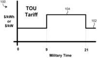
- a chart 100 illustrating “time of use” (TOU) energy pricingis shown, according to an exemplary embodiment.
- an energy providermay charge a baseline price 102 for energy used during an off-peak period and a relatively higher price 104 for energy used during an on-peak period. For example, during an off-peak period, energy may cost $0.10 per kWh whereas during an on-peak period, energy may cost $0.20 per kWh.
- Energy costmay be expressed as a cost per unit of energy using any measure of cost and any measure of energy (e.g., $/kWh, $/J, etc.).
- a chart 200 illustrating a critical-peak pricing (CPP) structureis shown, according to an exemplary embodiment.
- a high price 204may be charged for energy used during the CPP period.
- an energy providermay charge two to ten times the on-peak energy rate 202 during a CPP period.
- Certain days in a billing cyclemay designated as CPP days and the CPP period may be divided in two or more sub-periods.
- CPP periodsmay also have separate demand charges for each sub-period.
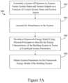
- process 400includes receiving an energy model for the building system (step 402 ).
- the energy model for the building systemi.e., the system model
- the energy modelmay be a mathematical representation of the building system and may be used to predict how the system will respond to various combinations of manipulated inputs and uncontrolled disturbances.
- the energy modelmay be used to predict the temperature or power usage of the building in response to a power or temperature setpoint (or other controlled variable).
- the energy modelmay describe the energy transfer characteristics of the building. Energy transfer characteristics may include physical traits of the building which are relevant to one or more forms of energy transfer (e.g., thermal conductivity, electrical resistance, etc.). Additionally, the energy model may describe the energy storage characteristics of the building (e.g., thermal capacitance, electrical capacitance, etc.) as well as the objects contained within the building. The energy transfer and energy storage characteristics of the building system may be referred to as system parameters.
- step 402may include receiving a pre-defined system model including all the information needed to accurately predict the building's response (e.g., all the system parameters). In other embodiments, step 402 may include developing the model (e.g., by empirically determining the system parameters).
- Step 402may include formulating a system of equations to express future system states and system outputs (e.g., future building temperature, future power usage, etc.) as a function of current system states (e.g., current building temperature, current power usage, etc.) and controllable system inputs (e.g., a power setpoint, a temperature setpoint, etc.). Step 402 may further include accounting for disturbances to the system (e.g., factors that may affect future system states and system outputs other than controllable inputs), developing a framework model using physical principles to describe the energy characteristics of the building system in terms of undefined system parameters, and obtaining system parameters for the framework model. Step 402 may be accomplished using process 500 , described in greater detail in reference to FIG. 5 .
- method 400may include receiving system state information (step 404 ).
- Receiving system state informationmay include conducting and/or receiving measurements or estimates of current building conditions (i.e., current states of the building system) such as building temperature, building power use, etc.).
- System state informationmay include information relating to directly measurable system states or may include estimated or calculated quantities. Materials within the building may have a thermal capacitance and therefore may be used to store a thermal load (e.g., a heating or cooling load).
- System state informationmay include an estimation of an amount of heat currently stored by the capacitive objects within the building.
- method 400may include receiving an energy cost function for the building system (step 406 ).
- the energy cost functionmay be used to calculate a total energy cost within a finite time horizon.
- Current system state informatione.g., measurements of current power usage
- predicted future system statese.g., estimated future power usage
- time-varying price informatione.g., off-peak, on-peak, critical peak, etc.
- Step 406may further include expressing the cost function as a liner equation by adding demand charge constraints to the optimization procedure and using a masking procedure to invalidate demand charge constraints for inactive pricing periods. Step 406 may be accomplished using a cost function definition process such as process 1300 , described in greater detail in reference to FIG. 13 .
- method 400may include using an optimization procedure to minimize the total energy cost for the building system (step 408 ).
- Step 408may include receiving temperature constraints, using the energy model and the system state information to formulate equality constraints, and determining an optimal power usage or setpoint to minimize the total cost of energy within a finite time horizon (e.g., minimize the energy cost determined by the cost function) while maintaining building temperature within acceptable bounds.
- Equality constraintsmay be used to guarantee that the optimization procedure considers the physical realities of the building system (e.g., energy transfer principles, energy characteristics of the building, etc.) during cost minimization.
- equality constraintsmay be used to predict the building's response (e.g., how the system states and outputs will change) to a projected power usage or temperature setpoint, thereby allowing the energy cost function to be minimized without violating the temperature constraints.
- Step 408may be accomplished using an optimization process such as process 1500 described in greater detail in reference to FIG. 15 .
- Process 500may be used to accomplish step 402 of method 400 .
- Process 500may include formulating a system of equations to express future system states and system outputs (e.g., future building temperature, future power use, etc.) as a function of current system states (e.g., current building temperature, current power use, etc.) and controllable inputs to the system (e.g., a power setpoint, a temperature setpoint, or other manipulated variables) (step 502 ).
- future system states and system outputse.g., future building temperature, future power use, etc.
- current system statese.g., current building temperature, current power use, etc.
- controllable inputs to the systeme.g., a power setpoint, a temperature setpoint, or other manipulated variables
- Process 500may further include accounting for disturbances to the system (e.g., factors other than controllable inputs) such as outside temperature or weather conditions that may affect future system states and system outputs (step 504 ). Additionally, process 500 may include developing a framework model using physical principles to describe the energy characteristics of the building system in terms of undefined system parameters (step 506 ), and obtaining system parameters for the framework model (step 508 ).
- disturbances to the systeme.g., factors other than controllable inputs
- process 500may include developing a framework model using physical principles to describe the energy characteristics of the building system in terms of undefined system parameters (step 506 ), and obtaining system parameters for the framework model (step 508 ).
- process 500may include formulating a system of equations to express future system states and system outputs as a function of current system states and controllable system inputs (step 502 ).
- a state space representationis used to express future system states and system outputs in discrete time as a function current system states and inputs to the system 502 .
- step 502may include formulating any type of equation (e.g., linear, quadratic, algebraic, trigonometric, differential, etc.) to express future system states.
- Timemay be expressed in discrete intervals (e.g., time-steps) by moving from a time-step k to the next time-step k+1.
- the system parametersmay be adaptively identified on a recursive basis to account for changes to the building system over time.
- a recursive system identification processis described in greater detail in reference to FIG. 12 .
- a change to the physical geometry of the systeme.g., knocking down a wall
- a change in disturbances to the systemsuch as heat transfer through the exterior walls (e.g., a change in weather), heat generated from people in the building, or heat dissipated from electrical resistance within the building (e.g., a load change) may not result in a change to the system parameters because no physical change to the building itself has occurred.
- process 500may include accounting for disturbances to the system (step 504 ).
- Disturbances to the systemmay include factors such as external weather conditions, heat generated by people in the building, or heat generated by electrical resistance within the building.
- disturbances to the systemmay include factors having an impact on system states (e.g., building temperature, building power use, etc.) other than controllable inputs to the system.
- system statese.g., building temperature, building power use, etc.
- an observer-based designmay be used to allow an estimation of the system states which may not be directly measurable. Additionally, such a design may account for measurement error in system states which have a noise distribution associated with their measurement (e.g., an exact value may not be accurately measurable).
- k )A ( ⁇ ) ⁇ circumflex over (x) ⁇ ( k
- k ⁇ 1)C ( ⁇ ) ⁇ circumflex over (x) ⁇ ( k
- Kis the Kalman gain and the hat notation ⁇ circumflex over (x) ⁇ , ⁇ implies an estimate of the state and output respectively.
- k)means the value at time step k+1 given the information at time step k. Therefore the first equation reads “the estimate of the states at time step k+1 given the information up to time step k” and the second equation reads “the estimate of the output at time step k given the information up to time step k ⁇ 1.” The estimate of the states and outputs are used throughout the cost minimization problem over the prediction and control horizons.
- process 500may further include developing a framework energy model of the building system using physical principles to describe the energy characteristics of the system in terms of undefined system parameters (step 506 ).
- the framework energy modelmay include generalized energy characteristics of the building system (e.g., thermal resistances, thermal capacitances, heat transfer rates, etc.) without determining numerical values for such quantities.
- model predictive controlmay be used to develop the framework energy model.
- MPCis a unifying control methodology that incorporates technologies of feedback control, optimization over a time horizon with constraints, system identification for model parameters, state estimation theory for handling disturbances, and a robust mathematical framework to enable a state of the art controller.
- An exemplary MPC controller 1700 and diagrams which may develop and use a framework energy modelare described in greater detail in reference to FIG. 5 B - FIG. 10 .
- a framework energy model for the building systemmay be developed (step 506 ) for two or more MPC controllers.
- process 500may further include obtaining system parameters for the framework energy model of the building system (step 508 ).
- the system parametersmay be specified in advance, imported from a previously identified system, received from a separate process, specified by a user, or otherwise received or retrieved.
- system parametersare identified using a system identification process such as process 1100 , described in greater detail in reference to FIG. 11 .
- MPC controller 1700may further include a processing circuit 1705 having a processor 1704 and memory 1706 .
- Processor 1704can be implemented as a general purpose processor, an application specific integrated circuit (ASIC), one or more field programmable gate arrays (FPGAs), a group of processing components, or other suitable electronic processing components.
- Memory 1706may include one or more devices (e.g., RAM, ROM, Flash memory, hard disk storage, etc.) for storing data and/or computer code for completing and/or facilitating the various processes, layers, and modules described in the present disclosure.
- Memory 1706may comprise volatile memory or non-volatile memory.
- Memory 1706may include database components, object code components, script components, or any other type of information structure for supporting the various activities and information structures described in the present disclosure.
- the memory 1706is communicably connected to the processor 1704 and includes computer instructions for executing (e.g., by the processor 1704 ) one or more processes described herein.
- Memory 1706may include an optimization module 1722 for completing an optimization procedure, an identification module 1724 for performing system identification, a state estimation module 1726 to estimate system states based on the data received via the communications interface 1702 , and a state prediction module 1728 to predict future system states.
- MPC controller 1700may compensate for an unmeasured disturbance to the system.
- MPC controller 1700may be referred to as an offset-free or zero-offset MPC controller.
- the integral mode in PID controllerserves to remove the steady state error of a variable.
- the state space modelcan be augmented with an integrating disturbance d, as shown in the following equation, to guarantee zero offset in the steady state:
- the number of integrating disturbances to introducemay equal the number of measurements needed to achieve zero offset, independent from tuning the controller.
- System 600may include an inner MPC controller 602 and an outer MPC controller 604 .
- Inner MPC controller 606may function within an inner control loop contained within an outer control loop. This inner-outer control loop architecture may be referred to as a “cascaded” control system.
- Cascaded MPC system 600 disclosed hereinhas several advantages over a single MPC controller.
- system 600may allow inner MPC controller 602 to operate at a shorter sampling and control interval to quickly reject disturbances while outer MPC controller 604 may operate at a longer sampling and control interval to maintain optimal power usage.
- the sampling and control execution time of inner MPC controller 602may be around thirty seconds whereas the sampling and control execution time of outer MPC controller 604 may be around fifteen minutes.
- the choice of fifteen minutesmay be driven by a frequency of changes in energy pricing data (e.g., in the real-time pricing rate structure, energy prices may change as frequently as once per fifteen minutes).
- longer or shorter control timesmay be used.
- the cascaded designadvantageously permits the development of a less complex energy model than could be achieved with a single comprehensive energy model for the entire building system.
- inner controller 602 and outer controller 604may be decoupled in location.
- the outer controller 604may be implemented off-site or “in the cloud” whereas the inner controller 602 may be run in an on-site building supervisory environment (e.g., a building controller local to a building).
- outer controller 604may receive input from multiple building systems and may interact with multiple inner controllers.
- inner MPC controller 602may be responsible for keeping the building's power use 612 (P B ) at a power setpoint 622 (P sp ) by modulating a temperature setpoint 624 (T sp ).
- Inner MPC controller 602may determine the necessary changes in the temperature setpoint 626 ( ⁇ dot over (T) ⁇ sp ). As shown, changes 626 may be integrated through integrator block 630 before being sent to the building system 606 as temperature setpoint 624 (T sp ).
- Outer MPC controller 604may use energy consumption and demand prices, 626 (C C,k ) and 628 (C D,k ) respectively, to determine an amount of power that should be deferred 632 (P D ).
- the deferred power 632may be subtracted from an estimated building load 636 .
- Feed forward predictor 640may determine the estimated building load 636 using past weather and power use data 638 .
- Inner MPC controller 702may receive a power setpoint 722 (P sp ) as an input.
- power setpoint 722may be an optimal power usage as determined by outer MPC controller 604 .
- historical weather and power usage data 638may be used to determine a typical building load 636 (e.g., a predicted or historical amount of energy needed to maintain the building temperature within temperature constraints). If a typical building load 636 is determined, outer MPC controller 604 may be used to determine an amount of power that should be deferred 632 .
- the amount of deferred power 632is subtracted from the typical building load 636 before being sent to the inner MPC controller 702 as a power setpoint 722 .
- the amount of deferred power 632may be positive (e.g., subtracted from the typical building load 636 ) or negative (e.g., added to the typical building load 636 ).
- inner MPC controller 702may further receive a zone temperature 714 (T z ) as an input.
- Zone temperature 714may be a variable representing a state of the system.
- zone temperature 714may be the measured temperature of the single building zone (e.g., a room, floor, area, combination of rooms or floors, etc.).
- zone temperature 714may be a weighted average of the temperatures of multiple building zones. In some embodiments, the weighted average may be based on the area or volume of one or more zones. Additionally, the weighted average may be based on the relative position of the zone temperatures within the demand response temperature range. For example, zone temperature 714 may be calculated as follows:
- Zone temperature 714may be measured directly, calculated from measured quantities (e.g., information representative of a measured temperature), or otherwise generated by the system.
- Information representative of a measured temperaturemay be the measured temperature itself or information from which a building temperature may be calculated.
- inner MPC controller 702may further receive a current power usage 712 of the building.
- Current power usage 712may be received as a feedback input for inner MPC controller 702 .
- Inner MPC controller 702may attempt to control current power usage 712 to match power setpoint 722 .
- current power usage 712is an amount of power currently used by the building.
- power usage 712may represent any other state of the system, depending on the variable or variables sought to be controlled.
- Power usage 712may be measured directly from the building system, calculated from measured quantities, or otherwise generated by any other method or process.
- inner MPC controller 702may output the derivative of a temperature setpoint ⁇ dot over (T) ⁇ sp 726 .
- the derivative of the temperature setpoint 726may be used by inner MPC controller 702 to control power usage 712 .
- ⁇ dot over (T) ⁇ sp 726may be a rate at which the temperature setpoint 624 is to be increased or decreased for the single zone.
- ⁇ dot over (T) ⁇ sp 726may be applied to the respective temperature setpoints for each individual zone.
- ⁇ dot over (T) ⁇ sp 726may be broken into multiple outputs using a weighted average calculation based on the relative positions of the zone temperatures within the demand response range.
- the derivative of the temperature setpoint 726may be chosen as the output of the inner MPC controller 702 because the system 606 is expected to perform as a “negative 1” type system.
- a step change in the temperature setpoint 624may cause a very small change in steady-state power usage. Therefore to prevent steady-state offset (or an offset the decays very slowly) the controller 702 may have two integrators.
- the first integratormay be implicit in the disturbance model of the MPC controller (e.g., included as an integrating disturbance) whereas the second integrator 630 may be explicitly located downstream of inner MPC controller 602 , as shown in FIG. 6 .
- the exemplary embodimentuses a derivative of temperature setpoint 726 as the output variable for the inner MPC controller 702 , other embodiments may use different output variables or additional output variables.
- Outer MPC controller 604may be responsible for calculating an amount of power to defer 632 , based on current and future energy prices 626 and 628 , while maintaining building temperature 614 within acceptable bounds. As long the temperature constraints are satisfied, temperature 614 may be allowed to fluctuate. Thus, the goal of the outer MPC controller 604 is to minimize the cost of energy subject to temperature constraints.
- outer MPC controller 804may receive the current zone temperature T z 814 and the current power usage P B 812 of the building system. As described in reference to FIG. 7 , these two variables represent states of building system 606 . Both states may be measured directly, calculated from measured quantities, or otherwise generated by building system 606 . In some embodiments, controller 804 may receive information representative of a measured temperature and/or information representative of a measured power usage. Information representative of a measured temperature may be the measured temperature itself or information from which a building temperature may be calculated. Information representative of a measured power usage may be the measured power usage itself or information from which a building power usage may be calculated.
- outer MPC controller 804may further receive pricing information 826 including energy consumption and demand prices, C C,k and C D,k respectively, according to an exemplary embodiment.
- the electric consumption price C C,kmay be the cost per unit of energy consumed (e.g., $/J or $/kWh).
- C C,kmay be applied as a multiplier to the total amount of energy used in a billing cycle, a pricing period, or any other time period to determine an energy consumption cost.
- the demand price C D,kmay be an additional charge corresponding to the peak power (e.g., maximum rate of energy use) at any given time during a billing period.
- Pricing information 826may include consumption and demand prices for one or more pricing periods or pricing levels including off-peak, partial-peak, on-peak, critical-peak, real-time, or any other pricing period or pricing level.
- pricing information 826may include timing information defining the times during which the various consumption prices and demand prices will be in effect.
- outer MPC controller 804may further receive historical weather and power usage data. Historical weather and power usage data may be used to perform a feed-forward estimation of the building's probable power requirements. However, in other embodiments, this estimation may performed by a separate feed-forward module 640 , as shown in FIG. 6 . In further embodiments, historical weather and power usage data are not considered by the outer MPC controller 804 in determining the optimal power setpoint 822 .
- Diagram 900may represent a framework energy model of the building system for the inner MPC controller.
- the building systemis modeled in diagram 900 as a single-zone building with a shallow mass and a deep mass.
- the shallow massmay represent objects and/or materials in the building which have contact with the air inside the building (e.g., immediate wall material, drywall, furniture, floor, ceiling, etc.)
- the deep massmay represent material which is separated from the air inside the building by the shallow mass (e.g., cement block, foundation, etc.).
- T, C, and Rare used to represent temperatures, capacitances, and resistances, respectively, with the associated subscripts d, s, z, and O representing deep mass, shallow mass, zone air, and outside air, respectively. Also shown is the heat supplied 932 by people and electric resistance within the building ( ⁇ dot over (Q) ⁇ L ), and the heat supplied 934 (or removed in the case of a negative number) by the HVAC system ( ⁇ dot over (Q) ⁇ HVAC ).
- the framework energy modelis simplified by eliminating C d , C s , and ⁇ dot over (Q) ⁇ L , thereby significantly reducing the number of parameters in the model.
- a reduced number of parametersmay increase the robustness of system identification and reduce the computational effort of the inner MPC controller.
- these time varying sources of heat entering the zone temperature node 914may be treated as a slowly moving disturbance.
- the slowly moving disturbance 940may be represented as ⁇ dot over (Q) ⁇ D which includes conduction and convection of outside air 942 , heat transfer from the shallow mass 944 , and heat generated from people and electrical use inside the building 932 .
- ⁇ dot over (Q) ⁇ HVAC 934may be modeled as the output of a PI controller.
- ⁇ dot over (Q) ⁇ HVAC 934represents the power delivered to the system
- additional equationsmay be introduced to compensate for the power lost in transportation.
- the energy balancemay be maintained by heating water in the building which may be transported to a chiller/tower system where the heat may be expelled into to the atmosphere.
- the transport process that converts the cooling power delivered to the building system to a power use at a cooling towermay be modeled by an over-damped second-order system with one (shorter) time constant ⁇ 1 representing the delay and a second time constant ⁇ 2 representing mass of cooling fluid.
- Pis the power used by the cooling equipment (e.g., at the cooling/chilling towers)
- P Bis the power usage as measured by the building
- K qis coefficient that converts PID output to heating power
- K eis coefficient that converts PID output to a steady-state power usage by the central plant equipment
- ⁇ 1 and ⁇ 2are the time constants of the power transport process.
- the entire model needed by the inner MPC controller 602can be represented by:
- modeling P Dist in such a waymay allow for offset free control in the presence of slowly changing disturbances.
- the complete inner loop framework energy modelmay be given by:
- a Kalman gain(used in the state estimation process) may be used to optimally convert measurement errors to state estimation error, thereby causing P Dist to change.
- Diagram 1000may represent a framework energy model of the building system for the outer MPC controller.
- FIG. 10 ( a )a complete energy diagram for the outer loop framework energy model is shown, according to an exemplary embodiment.
- all forms of capacitance 1002 , 1004 , and 1006 in the buildingmay be included in the model because it may no longer be sufficient to treat the heat transfer from the shallow mass 1044 as a slowly moving disturbance.
- knowledge of the states of these capacitors and how heat is transferred between themmay be relevant to a prediction of how zone temperature 1014 will change.
- an objective of the outer loop modelmay be to predict the state of these capacitors.
- FIG. 10 ( b )a simplified energy diagram for the outer loop framework energy model is shown.
- Two simplifying assumptionsmay be made in converting the complete energy diagram ( FIG. 10 ( a ) ) to the simplified energy diagram ( FIG. 10 ( b ) ).
- the energy transferred through external conduction and convection 1042 and the typical load profile at a constant setpoint ⁇ dot over (Q) ⁇ L2 1032can be estimated based on time of day and temperature difference between the outside air temperature 1048 and the zone 1014 (e.g., T o ⁇ T z ).
- Estimationmay performed by the feed forward load predictor 640 shown in FIG. 6 .
- the random portion of the load profile(e.g., the portion that is independent of time of day and temperature difference) may be represented an integrated disturbance ⁇ dot over (Q) ⁇ D2 1040 .
- energy transfer equations describing the model shown in FIG. 10 ( b )may be expressed as:
- the heat transfersmay be converted to powers that can be measured at the meter by assuming a constant of proportionality between the two. For example, ⁇ dot over (Q) ⁇ HVAC may be converted to P HVAC by multiplying by a coefficient of performance.
- inputs to the outer MPC controller 604may be divided into controllable inputs, measured disturbances (e.g., uncontrollable but measurable inputs), and unmeasured disturbances (e.g., uncontrollable and unmeasured inputs).
- the inputsmay be reformulated to P C (e.g., the power required to keep the zone temperature constant) and P D (e.g., the deferred power).
- P Ce.g., the power required to keep the zone temperature constant
- P De.g., the deferred power
- P Dmay be a controllable input because it may be possible to control the amount of power to defer.
- P Cmay be a measured disturbance because it may be possible to estimate the power required maintain a constant building temperature based the difference between outdoor air temperature and the temperature within the building.
- estimation of P C(P L2 and the portion of P HVAC that comes from a constant setpoint) may be performed in a feed forward fashion as shown in FIG. 6 .
- P D2may be an unmeasured disturbance and can be viewed as the estimation error in P C .
- the framework energy model of the building system used by the outer MPC controllermay be expressed as:
- P Cf(T OA ⁇ T z ,t)
- the outer loop modelcan be simplified further by assuming that changes in the deep mass temperature 1052 (T d ) occur at a rate that is much slower than the length of time power use can be deferred.
- T dthe temperature of the deep mass 1052
- the framework energy model used by outer MPC controller 604may be expressed as:
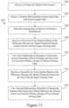
- process 1100may include receiving a framework energy model for the building system (step 1102 ), receiving training data including system input data and system output data (step 1104 ), filtering the training data to remove extraneous disturbances (step 1106 ), receiving a first error cost function based on the difference between the filtered output training data and a model-predicted filtered output (step 1108 ), and using a first optimization procedure to determine system parameters which minimize the first error cost function within a range of filtered training data (step 1110 ).
- the first error cost functionmay be used to determine the cost of prediction error within a range of filtered training data.
- the range of filtered training datamay comprise the entire set of training data or a subset thereof.
- the training data used by the first error cost functionmay be automatically specified, chosen by a user, or otherwise determined by any other method or process.
- ⁇ circumflex over ( ⁇ ) ⁇ ( k+ 1)⁇ circumflex over ( ⁇ ) ⁇ ( k )+ ⁇ ⁇ ⁇ ⁇ ⁇ 1 [y ( k ) ⁇ ⁇ ( k
- k ⁇ 1)] T ⁇ , ⁇ ⁇E ⁇ [ ⁇ right arrow over (y) ⁇ ( k ) ⁇ ⁇ ( k
- the state estimatemay be resolved by assuming that the state estimate is equal to the actual state for a given parameter value. While this may not be true due to noise in the system, it may asymptotically true in terms of the expected parameter values. Because the system state estimates are also functions of the model parameters, can then be written as,
- ⁇ ( ⁇ ; k )C ⁇ ( ⁇ ) ⁇ d d ⁇ ⁇ ⁇ ⁇ x ⁇ ⁇ ( ⁇ ; k
- the derivatives of the matrices C and Dmay be determined by the model parameters, whereas the derivative of the state estimate ⁇ may be estimated recursively using in the following equation:
- ⁇ ⁇ ( ⁇ ; k + 1 )⁇ d d ⁇ ⁇ ⁇ ⁇ x ⁇ ⁇ ( ⁇ ; k + 1
- k )d d ⁇ ⁇ ⁇ ⁇ [ A ⁇ ( ⁇ ) ⁇ x ⁇ ⁇ ( ⁇ ; k
- k - 1 ) + B ⁇ ( ⁇ ) ⁇ u ⁇ ( k ) + K ⁇ ( ⁇ ) ⁇ ⁇ ⁇ ( k ) ] ,⁇ A ⁇ ( ⁇ ) ⁇ ⁇ ⁇ ( ⁇ ; k ) - K ⁇ ( ⁇ ) ⁇ ⁇ ⁇ ( ⁇ ; k ) + ⁇ [ dA d ⁇ ⁇ ⁇ 1 ⁇ x ⁇ ⁇ ( ⁇ ; k
- recursive system identification process 1200may use the following restated equations to estimate updated values for the model parameters each time a new measurement is obtained (step 1202 ): ⁇ ( k
- k ⁇ 1)C ( ⁇ circumflex over ( ⁇ ) ⁇ ( k ))( k
- k ⁇ 1)+ D ( ⁇ circumflex over ( ⁇ ) ⁇ ( k )) u ( k ) ⁇ ( k )y ( k ) ⁇ ⁇ ( k
- Process 1200may further include includes using the updated model parameters to estimate the system states (step 1206 ).
- An EKFcould be developed to estimate both the system states and the model parameters simultaneously; however, this configuration may not converge if the noise properties of the system are unknown. Therefore, in an exemplary embodiment, system states may be estimated using a Kalman gain which is dependent on the model parameters according to the following difference equations: ⁇ circumflex over (x) ⁇ ( k+ 1
- k )A ( ⁇ circumflex over ( ⁇ ) ⁇ ( k )) ⁇ circumflex over (x) ⁇ ( k
- k ⁇ 1)+ B ( ⁇ circumflex over ( ⁇ ) ⁇ ( k )) u ( k )+ K ( ⁇ circumflex over ( ⁇ ) ⁇ ( k )) ⁇ ( k ), P ⁇ ( k+ 1)P ⁇ ( k )+ Q p +L ( k )[ ( k ) P ⁇ ( k ) T ( k )+ R]L T
- process 1200may further include checking the estimated model parameters for stability and robustness (step 1204 ) and reverting to previous model parameters if the estimated model parameters are either unstable or non-robust (step 1208 ).
- step 1204may be accomplished using the estimated model parameters to update the difference equations shown above and then checking the updated equations for stability.
- the difference equationsmay be stable if, for the domain , the parameters are such that the eigenvalues of A ⁇ KC are strictly less than one. In other words: ⁇ ⁇ d iff eig ⁇ A ( ⁇ ) ⁇ K ( ⁇ ) C ( ⁇ ) ⁇ 1
- the parameter update equationmay be replaced with:
- ⁇ ⁇ ⁇ ( k + 1 )⁇ ⁇ ⁇ ⁇ ( k ) + L ⁇ ( k ) ⁇ ⁇ ⁇ ( k ) , ⁇ ⁇ ⁇ ( k ) + L ⁇ ( k ) ⁇ ⁇ ⁇ ( k ) ⁇ ⁇ ⁇ ⁇ ( k ) , ⁇ ⁇ ⁇ ( k ) + L ⁇ ( k ) ⁇ ⁇ ⁇ ( k ) ⁇ ⁇ ⁇ ( k ) ⁇ Therefore, in some embodiments, the model parameters are not updated (step 1208 ) (e.g., the estimated value is not used and the parameters revert to their previous values) if the estimated values would result in instability.
- process 1200achieves improved robustness by considering the effect of outlying raw data.
- the gradient of the cost function(at a given sample) may be stated as ⁇ .
- process 1200may be a modified descent process in which the EKF equations (e.g., the parameter update equations used in step 1202 ) are used to scale and modify the direction of the descent.
- the gradient of the cost functionmay be stated as:
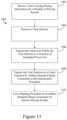
- process 1300may include receiving pricing information including energy charge information and demand charge information for a plurality pricing periods (step 1302 ).
- pricing informationmay include only energy charge information or only demand charge information or such information may pertain to only one pricing period.
- Energy charge informationmay include the cost of energy for some or all of the pricing periods.
- the cost of energyis defined on a per-unit basis (e.g., $/Joule, $/kWh, etc.).
- energy costmay be defined on a progressive or regressive basis, segmented into one or more fixed-cost ranges of energy use, or make use of any other cost structure.
- Demand charge informationmay include a cost corresponding to the peak power usage during one or more of the pricing periods (e.g., the maximum power used at any given time within a pricing period or combination of periods).
- the demand chargemay be imposed for some or all of the pricing periods and pricing periods may overlap (e.g., an “anytime” period would overlap with any other period or periods).
- the demand charge informationmay define the cost of power on a per-unit basis (e.g., $/W, $/kW, etc.).
- the demand chargemay be imposed on a progressive or regressive basis, segmented into one or more fixed-cost ranges of maximum power use, or make use of any other cost structure.
- pricing periodsmay include two or more different periods chosen from the group consisting of: off-peak, partial-peak, on-peak, critical-peak, and real-time. However, in other embodiments, more or fewer pricing periods may be used.
- the critical-peak pricing periodmay be subdivided into several sub-periods having different energy charges, different demand charges, or both, as shown in FIG. 2 .
- Two or more pricing periodsmay overlap and gaps may exist during which no pricing period is active.
- a pricing periodmay become inactive at a specified time and reactivate at a later time while still qualifying as the same pricing period (e.g., the on-peak period may recur every day from 9:00 A.M. until 9:00 P.M. as shown in FIG. 1 ).
- Energy charge information, demand charge information, and pricing period informationmay be received from the same source or from different sources, concurrently or at different times.
- process 1300may further include receiving a time horizon (step 1304 ).
- a time horizonmay define how far into the future to look when predicting future system states or planning future system inputs.
- the time horizonmay function as a prediction horizon, a control horizon, or both, depending on the application of the control system.
- a prediction horizonmay be used by the optimization procedure 1500 to define a time period during which the cost function is minimized.
- the control horizonmay be used by the optimization procedure 1500 to define a time period during which the manipulated inputs to the system may be controlled.
- the time horizonmay be used as both the prediction horizon and the control horizon and may be set to 5 r (e.g., five times a time constant of the system). However, in other embodiments, other time horizons may be used.
- the time horizonmay be used by both the optimization procedure 1500 to minimize the cost function and by the masking procedure 1310 to selectively mask the inactive demand charge constraints.
- process 1300may further include using the time-varying pricing information and the time horizon to express the total cost within the time horizon as a function of estimated power use (step 1306 ).
- the optimization problemcan be stated mathematically as minimizing the cost function:
- P Rrepresents the maximum power in the region from previous time steps in the billing cycle.
- P Rrepresents the maximum power in the region from previous time steps in the billing cycle.
- the value of P Rmay initially be zero at the beginning of a billing cycle and may increase due to constraints on the zone temperature T z .
- FIG. 16a flowchart of a process 1600 illustrating a recursive implementation of process 1500 is shown, according to an exemplary embodiment.
- process 1600may further include using the system state information to formulate demand charge constraints (step 1604 ).
- An example demand charge constraintmay be stated as (P i ⁇ P j ) k ⁇ P R where P R represents the maximum power in the demand charge region from previous time steps in the billing cycle.
- system state informationmay information regarding estimated or actual power use for a previous time-step. Thus, system state information may be used to resolve the value of P R in a demand charge constraint.
- Step 1604may be substantially equivalent to step 1308 in process 1300 .
- process 1600may further include using the masking procedure to invalidate the demand charge constraints which apply to inactive pricing periods (step 1606 ).
- step 1606may be performed because not all of the demand charge constraints are valid for each discrete time step used in the optimization procedure. In other embodiments, only valid demand charge constraints may be initially imposed and step 1606 may be unnecessary.
- process 1600may further include using the system model and system state information to formulate equality constraints (step 1608 ).
- Step 1608may allow the optimization procedure to accurately predict the effects of changing inputs to the building system so that the cost function can be minimized without violating the temperature constraints.
- process 1600may further include determining an optimal power usage which minimizes the total energy cost as determined by the cost function within a time horizon while satisfying the equality constraints, the temperature constraints, and the demand charge constraints (step 1610 ).
- Many minimization procedurescan be employed to perform cost minimization including Gauss-Newton, Ninness-Wills, adaptive Gauss-Newton, Gradient Descent, Levenberg-Marquardt, or any other optimization or search algorithm.
- process 1600may further include updating the system model and system state information (step 1612 ).
- Step 1612may be accomplished using recursive system identification process 1200 , batch system identification process 1100 or any other update process.
- the updated system model and system state informationmay be used to update the equality constraints and demand charge constraints a subsequent iteration of the recursive process.
- the system state informationmay include power usage information for previous time-steps. This information may be used to update the value of P R if necessary (e.g., if the power used during the last unrecorded time-step was greater than the stored value of P R ) so that P R continues to represent the maximum power used in a demand charge region during the current billing cycle.
- Steps 1604 - 1612may be performed recursively.
- the present disclosurecontemplates methods, systems and program products on any machine-readable media for accomplishing various operations.
- the embodiments of the present disclosuremay be implemented using existing computer processors, or by a special purpose computer processor for an appropriate system, incorporated for this or another purpose, or by a hardwired system.
- Embodiments within the scope of the present disclosureinclude program products comprising machine-readable media for carrying or having machine-executable instructions or data structures stored thereon.
- Such machine-readable mediacan be any available media that can be accessed by a general purpose or special purpose computer or other machine with a processor.
Landscapes
- Business, Economics & Management (AREA)
- Accounting & Taxation (AREA)
- Engineering & Computer Science (AREA)
- Economics (AREA)
- General Business, Economics & Management (AREA)
- General Physics & Mathematics (AREA)
- Strategic Management (AREA)
- Theoretical Computer Science (AREA)
- Physics & Mathematics (AREA)
- Finance (AREA)
- Health & Medical Sciences (AREA)
- Water Supply & Treatment (AREA)
- Public Health (AREA)
- Development Economics (AREA)
- General Health & Medical Sciences (AREA)
- Human Resources & Organizations (AREA)
- Marketing (AREA)
- Primary Health Care (AREA)
- Tourism & Hospitality (AREA)
- Supply And Distribution Of Alternating Current (AREA)
- Management, Administration, Business Operations System, And Electronic Commerce (AREA)
Abstract
Description
x(k+1)=Ax(k)±Bu(k)
y(k)=Cx(k)+Du(k)
where x represents the states of the system, u represents the manipulated variables which function as inputs to the system, and y represents the outputs of the system. Time may be expressed in discrete intervals (e.g., time-steps) by moving from a time-step k to the next time-step k+1.
x(k+1)=A(θ)x(k)+B(θ)u(k)
y(k)=C(θ)x(k)+D(θ)u(k)
where θ represents variable parameters in the system. A change to the physical geometry of the system (e.g., knocking down a wall) may result in a change to the system parameters. However, a change in disturbances to the system such as heat transfer through the exterior walls (e.g., a change in weather), heat generated from people in the building, or heat dissipated from electrical resistance within the building (e.g., a load change) may not result in a change to the system parameters because no physical change to the building itself has occurred.
x(k+1)=A(θ)x(k)+B(θ)u(k)+w(k)
y(k)=C(θ)x(k)+D(θ)u(k)+v(k)
w(k)˜N(0,Q)v(k)˜N(0,R)
where w and v are disturbance and measurement noise variables. The solution to this state estimation problem may be given by the function:
{circumflex over (x)}(k+1|k)=A(θ){circumflex over (x)}(k|k−1)+B(θ)u(k)+(θ)[y(k)−ŷ(k|k−1)]
ŷ(k|k−1)=C(θ){circumflex over (x)}(k|k−1)+D(θ)u(k),{circumflex over (x)}(0;θ)
where K is the Kalman gain and the hat notation {circumflex over (x)}, ŷ implies an estimate of the state and output respectively. The notation (k+1|k) means the value at time step k+1 given the information at time step k. Therefore the first equation reads “the estimate of the states at time step k+1 given the information up to time step k” and the second equation reads “the estimate of the output at time step k given the information up to time step k−1.” The estimate of the states and outputs are used throughout the cost minimization problem over the prediction and control horizons.
The number of integrating disturbances to introduce may equal the number of measurements needed to achieve zero offset, independent from tuning the controller.
where w is the weight of a zone and Tmaxand Tminrepresent the minimum and maximum allowable temperatures for that zone. In this case, the variable representing the zone temperatures may be normalized (e.g., between 0 and 1).
Cz{dot over (T)}z=Kq[Kp(Tsp−Tz)+KII]+{dot over (Q)}D
and the integral may be given by:
İ=Tsp−TZ
{umlaut over (P)}+(τ1+τ2){dot over (P)}+(τ1τ2)P=Pss
Pss=Ke[Kp(Tsp−Tz)+KII]
The additional values that have been introduced are defined as follows: P is the power used by the cooling equipment (e.g., at the cooling/chilling towers), PBis the power usage as measured by the building, Kqis coefficient that converts PID output to heating power, Keis coefficient that converts PID output to a steady-state power usage by the central plant equipment, and τ1and τ2are the time constants of the power transport process.
where {dot over (Q)}D940 as well as any power usage by loads other than HVAC equipment may be incorporated into the power disturbance PDist, which may be added to the measured
Although the discrete time model shows PDistas a constant, a Kalman gain (used in the state estimation process) may be used to optimally convert measurement errors to state estimation error, thereby causing PDistto change.
To convert these equations to the framework energy model used by
and the framework energy model used by the outer MPC controller can be expressed as:
In both models, terms representing the slowly moving disturbances may be removed as these disturbances may be subsequently accounted for using a Kalman gain, described in greater detail in reference to

which may be optimal for normally distributed errors, but sensitive to outliers:
with a parameterized Kalman gain of:
with a parameterized Kalman gain of:
The parameters in the A and B matrices may be held constant at the values identified by the first optimization procedure while K is determined by the second optimization procedure using the non-filtered training data.
xk=Axk+Buk⇒x0=(I−A)−1Bu0.
To solve this problem, it can be assumed that because the system states are at a steady-state and the temperature setpoint is constant, the zone temperature Tzis equal to the temperature setpoint. Additionally, the measured power may be assumed to be unchanging (e.g., {dot over (P)}Δ=0) and can be attributed to the heat disturbances. Finally, at the steady-state, powers PΔand PCmay be interchangeable; therefore, PΔmay be set to zero and PCmay be set to the current power usage. In this way, the state of the integrator can also be initialized to zero. With these assumptions in place, the
{circumflex over (θ)}(k+1)={circumflex over (θ)}(k)+L(k)[y(k)−ŷ(k|k−1)],
L(k)=Pθ(k)

Pθ(k+1)=Pθ(k)+Qp+L(k)[
where the state update matrix is the identity matrix and Pθ(k) is the parameter estimation error covariance. To calculate the time varying equivalent to the measurement equation, C, for the EKF, the generic update equation for normal distributions may be used, as shown in the following equations:
{circumflex over (θ)}(k+1)={circumflex over (θ)}(k)+ΣθωΣωω−1[y(k)−ŷ(k|k−1)],
Pθ(k+1)=Pθ(k)+QP+ΣθωΣωω−1ΣθωT
Σθω=E{[{circumflex over (θ)}(k)−θ(k)][y(k)−ŷ(k|k−1)]T},
Σωω=E{[{right arrow over (y)}(k)−ŷ(k|k−1)][y(k)−ŷ(k|k−1)]T}.
where Σθω and Σωω are the cross covariance between the parameter estimation error and the output estimation error and the covariance of the output estimation error, respectively. To calculate these to covariance matrices recursively and obtain the EKF equations shown above, the actual measurement may be approximated linearly as:
and used to update the parameter estimates in the EKF equations shown above.
and using the product rule, as:
ŷ(k|k−1)=C({circumflex over (θ)}(k))(k|k−1)+D({circumflex over (θ)}(k))u(k)
ε(k)=y(k)−ŷ(k|k−1)

L(k)=Pθ(k)
{circumflex over (θ)}(k+1)={circumflex over (θ)}(k)+L(k)ε(k)
{circumflex over (x)}(k+1|k)=A({circumflex over (θ)}(k)){circumflex over (x)}(k|k−1)+B({circumflex over (θ)}(k))u(k)+K({circumflex over (θ)}(k))ε(k),
Pθ(k+1)=Pθ(k)+Qp+L(k)[
η(k+1)=A({circumflex over (θ)}(k))η(k)−K({circumflex over (θ)}(k))


which follow from the derivation above.

θ∈

Thus, to keep the difference equations stable, the parameter update equation may be replaced with:
Therefore, in some embodiments, the model parameters are not updated (step1208) (e.g., the estimated value is not used and the parameters revert to their previous values) if the estimated values would result in instability.
which when applied to the following cost function, becomes:
Thus, in
Tmini<Tz,i<Tmax,i∀i
However, only the first term of this function is linear. The second term of the cost function includes a “max” operation which selects the maximum power usage at any given time during the relevant pricing period.
(Pi−Pj)k≤PR
for all i samples within a time horizon and for all j demand charge regions (e.g., pricing periods), where PRrepresents the maximum power in the region from previous time steps in the billing cycle. For example, the value of PRmay initially be zero at the beginning of a billing cycle and may increase due to constraints on the zone temperature Tz.
Claims (21)
Priority Applications (1)
| Application Number | Priority Date | Filing Date | Title |
|---|---|---|---|
| US16/723,830US12354174B2 (en) | 2013-03-13 | 2019-12-20 | Systems and methods for cascaded model predictive control |
Applications Claiming Priority (3)
| Application Number | Priority Date | Filing Date | Title |
|---|---|---|---|
| US13/802,154US9852481B1 (en) | 2013-03-13 | 2013-03-13 | Systems and methods for cascaded model predictive control |
| US15/808,388US10580097B2 (en) | 2013-03-13 | 2017-11-09 | Systems and methods for cascaded model predictive control |
| US16/723,830US12354174B2 (en) | 2013-03-13 | 2019-12-20 | Systems and methods for cascaded model predictive control |
Related Parent Applications (1)
| Application Number | Title | Priority Date | Filing Date |
|---|---|---|---|
| US15/808,388ContinuationUS10580097B2 (en) | 2013-03-13 | 2017-11-09 | Systems and methods for cascaded model predictive control |
Publications (2)
| Publication Number | Publication Date |
|---|---|
| US20200143491A1 US20200143491A1 (en) | 2020-05-07 |
| US12354174B2true US12354174B2 (en) | 2025-07-08 |
Family
ID=60674708
Family Applications (3)
| Application Number | Title | Priority Date | Filing Date |
|---|---|---|---|
| US13/802,154Active2035-04-18US9852481B1 (en) | 2013-03-13 | 2013-03-13 | Systems and methods for cascaded model predictive control |
| US15/808,388Active2033-11-30US10580097B2 (en) | 2013-03-13 | 2017-11-09 | Systems and methods for cascaded model predictive control |
| US16/723,830Active2033-07-24US12354174B2 (en) | 2013-03-13 | 2019-12-20 | Systems and methods for cascaded model predictive control |
Family Applications Before (2)
| Application Number | Title | Priority Date | Filing Date |
|---|---|---|---|
| US13/802,154Active2035-04-18US9852481B1 (en) | 2013-03-13 | 2013-03-13 | Systems and methods for cascaded model predictive control |
| US15/808,388Active2033-11-30US10580097B2 (en) | 2013-03-13 | 2017-11-09 | Systems and methods for cascaded model predictive control |
Country Status (1)
| Country | Link |
|---|---|
| US (3) | US9852481B1 (en) |
Families Citing this family (56)
| Publication number | Priority date | Publication date | Assignee | Title |
|---|---|---|---|---|
| US8843238B2 (en)* | 2011-09-30 | 2014-09-23 | Johnson Controls Technology Company | Systems and methods for controlling energy use in a building management system using energy budgets |
| US10101730B2 (en) | 2014-05-01 | 2018-10-16 | Johnson Controls Technology Company | Incorporating a load change penalty in central plant optimization |
| US10031494B2 (en) | 2014-08-15 | 2018-07-24 | Honeywell International Inc. | Dashboard and button/tile system for an interface |
| US10190789B2 (en) | 2015-09-30 | 2019-01-29 | Johnson Controls Technology Company | Central plant with coordinated HVAC equipment staging across multiple subplants |
| US10250039B2 (en) | 2015-10-08 | 2019-04-02 | Con Edison Battery Storage, Llc | Energy storage controller with battery life model |
| US10700541B2 (en) | 2015-10-08 | 2020-06-30 | Con Edison Battery Storage, Llc | Power control system with battery power setpoint optimization using one-step-ahead prediction |
| US10186889B2 (en) | 2015-10-08 | 2019-01-22 | Taurus Des, Llc | Electrical energy storage system with variable state-of-charge frequency response optimization |
| US10181165B2 (en)* | 2016-02-12 | 2019-01-15 | Fujitsu Limited | Critical peak pricing demand response participant assessment |
| US10423735B2 (en)* | 2016-06-29 | 2019-09-24 | International Business Machines Corporation | Hybrid modeling for a device under test associated with a two-phase cooling system |
| US10778012B2 (en) | 2016-07-29 | 2020-09-15 | Con Edison Battery Storage, Llc | Battery optimization control system with data fusion systems and methods |
| WO2018098575A1 (en)* | 2016-11-29 | 2018-06-07 | Peak Power Inc. | System and method for dynamic energy storage system control |
| US10337753B2 (en)* | 2016-12-23 | 2019-07-02 | Abb Ag | Adaptive modeling method and system for MPC-based building energy control |
| US12071036B2 (en) | 2019-09-06 | 2024-08-27 | Netzero V2G Technologies Llc | Minimum cost demand charge management by electric vehicles |
| US10423138B2 (en)* | 2017-03-06 | 2019-09-24 | Con Edison Battery Storage, Llc | Building energy storage system with planning tool |
| EP3601895B1 (en) | 2017-03-31 | 2023-03-01 | Honeywell International Inc. | Method for providing a comfort dashboard and non-transitory computer-readable medium |
| US10146237B2 (en) | 2017-04-28 | 2018-12-04 | Johnson Controls Technology Company | Smart thermostat with model predictive control |
| US11274849B2 (en) | 2017-04-28 | 2022-03-15 | Johnson Controls Tyco IP Holdings LLP | Smart thermostat with model predictive control and demand response integration |
| US10670287B2 (en)* | 2017-05-10 | 2020-06-02 | Cenergistic Llc | Building automation and control system modeling and reporting |
| US12085296B2 (en) | 2017-05-26 | 2024-09-10 | Tyco Fire & Security Gmbh | Building equipment with predictive control and allocation of energy from multiple energy sources |
| US10571146B2 (en)* | 2017-05-26 | 2020-02-25 | Johnson Controls Technology Company | Air handling unit and rooftop unit with predictive control |
| US10935940B2 (en) | 2017-08-03 | 2021-03-02 | Johnson Controls Technology Company | Building management system with augmented deep learning using combined regression and artificial neural network modeling |
| US11159022B2 (en) | 2018-08-28 | 2021-10-26 | Johnson Controls Tyco IP Holdings LLP | Building energy optimization system with a dynamically trained load prediction model |
| US11163271B2 (en) | 2018-08-28 | 2021-11-02 | Johnson Controls Technology Company | Cloud based building energy optimization system with a dynamically trained load prediction model |
| US12393992B2 (en) | 2018-10-18 | 2025-08-19 | Tyco Fire & Security Gmbh | Systems and methods for assessing and controlling sustainability of an energy plant |
| US11960261B2 (en) | 2019-07-12 | 2024-04-16 | Johnson Controls Tyco IP Holdings LLP | HVAC system with sustainability and emissions controls |
| US12007732B2 (en) | 2019-07-12 | 2024-06-11 | Johnson Controls Tyco IP Holdings LLP | HVAC system with building infection control |
| US10830474B2 (en)* | 2018-11-06 | 2020-11-10 | Lennox Industries Inc. | Systems and methods of predicting energy usage |
| US11210591B2 (en)* | 2019-01-04 | 2021-12-28 | Johnson Controls Tyco IP Holdings LLP | Building control system with automated Kalman filter parameter initiation and system identification |
| KR102544265B1 (en)* | 2019-01-09 | 2023-06-16 | 삼성전자주식회사 | Electronic device and control method thereof |
| US10978199B2 (en) | 2019-01-11 | 2021-04-13 | Honeywell International Inc. | Methods and systems for improving infection control in a building |
| US11592792B2 (en) | 2019-01-30 | 2023-02-28 | Johnson Controls Tyco IP Holdings LLP | Energy control system with energy provider level demand optimization |
| US11226600B2 (en) | 2019-08-29 | 2022-01-18 | Johnson Controls Tyco IP Holdings LLP | Building control system with load curtailment optimization |
| US11274842B2 (en) | 2019-07-12 | 2022-03-15 | Johnson Controls Tyco IP Holdings LLP | Systems and methods for optimizing ventilation, filtration, and conditioning schemes for buildings |
| US11714393B2 (en) | 2019-07-12 | 2023-08-01 | Johnson Controls Tyco IP Holdings LLP | Building control system with load curtailment optimization |
| CN114364926B (en) | 2019-07-12 | 2024-04-05 | 江森自控泰科知识产权控股有限责任合伙公司 | HVAC systems with design and operation tools for infection control in buildings |
| US12264828B2 (en) | 2019-07-12 | 2025-04-01 | Tyco Fire & Security Gmbh | Air quality control and disinfection system |
| US11099529B2 (en) | 2019-07-23 | 2021-08-24 | International Business Machines Corporation | Prediction optimization for system level production control |
| US11099530B2 (en) | 2019-08-23 | 2021-08-24 | Johnson Controls Technology Company | Central plant control system with device geometric modeling and control |
| US11144020B2 (en) | 2019-08-23 | 2021-10-12 | Johnson Controls Tyco IP Holdings LLP | Central plant control system with geometric modeling of operational sequences |
| KR20210033769A (en)* | 2019-09-19 | 2021-03-29 | 삼성전자주식회사 | Electric apparatus and operation method of the electric apparatus |
| US12071020B2 (en) | 2019-09-24 | 2024-08-27 | Netzero V2G Technologies Llc | Electric vehicle service equipment adapter module to control added loads |
| US11662113B2 (en) | 2019-11-18 | 2023-05-30 | Johnson Controls Tyco IP Holdings LLP | Building cooling systems with energy optimization and model predictive control |
| KR20210093015A (en) | 2020-01-17 | 2021-07-27 | 삼성전자주식회사 | The method for predicting in sequential data and apparatus thereof |
| US11913659B2 (en) | 2020-06-15 | 2024-02-27 | Honeywell International Inc. | Systems and methods for monitoring operation of an HVAC system |
| US20210390474A1 (en) | 2020-06-15 | 2021-12-16 | Honeywell International Inc. | Dashboard for multi site management system |
| US11823295B2 (en) | 2020-06-19 | 2023-11-21 | Honeywell International, Inc. | Systems and methods for reducing risk of pathogen exposure within a space |
| US12131828B2 (en) | 2020-06-22 | 2024-10-29 | Honeywell Internationa Inc. | Devices, systems, and methods for assessing facility compliance with infectious disease guidance |
| US11894145B2 (en) | 2020-09-30 | 2024-02-06 | Honeywell International Inc. | Dashboard for tracking healthy building performance |
| US11372383B1 (en) | 2021-02-26 | 2022-06-28 | Honeywell International Inc. | Healthy building dashboard facilitated by hierarchical model of building control assets |
| US12398905B2 (en) | 2021-05-28 | 2025-08-26 | Tyco Fire & Security Gmbh | Building control system with multi-objective control of carbon emissions and occupant comfort |
| US12261434B2 (en) | 2022-02-10 | 2025-03-25 | Tyco Fire & Security Gmbh | Control system with multi-factor carbon emissions optimization |
| WO2023044134A1 (en) | 2021-09-20 | 2023-03-23 | Johnson Controls Tyco IP Holdings LLP | Systems and methods for sustainability planning for a building |
| CN113629748B (en)* | 2021-10-11 | 2022-03-11 | 国网江西省电力有限公司电力科学研究院 | Five-level energy storage converter cascade model prediction control method and device |
| US11761663B2 (en)* | 2021-11-19 | 2023-09-19 | Johnson Controls Tyco IP Holdings LLP | HVAC system for reducing intra-space variation of controlled environmental conditions |
| US12386325B2 (en) | 2022-04-28 | 2025-08-12 | Inventus Holdings, Llc | Staggered cooling system controls for battery energy storage systems |
| US12431621B2 (en) | 2023-01-26 | 2025-09-30 | Honeywell International Inc. | Compact dual band antenna |
Citations (264)
| Publication number | Priority date | Publication date | Assignee | Title |
|---|---|---|---|---|
| US4061185A (en)* | 1975-05-16 | 1977-12-06 | Canada Square Management Ltd. | Temperature control system |
| US4349869A (en)* | 1979-10-01 | 1982-09-14 | Shell Oil Company | Dynamic matrix control method |
| US4616308A (en)* | 1983-11-15 | 1986-10-07 | Shell Oil Company | Dynamic process control |
| US5289362A (en)* | 1989-12-15 | 1994-02-22 | Johnson Service Company | Energy control system |
| US5301101A (en)* | 1990-06-21 | 1994-04-05 | Honeywell Inc. | Receding horizon based adaptive control having means for minimizing operating costs |
| US5347446A (en)* | 1991-02-08 | 1994-09-13 | Kabushiki Kaisha Toshiba | Model predictive control apparatus |
| US5351184A (en)* | 1993-01-26 | 1994-09-27 | Honeywell Inc. | Method of multivariable predictive control utilizing range control |
| US5408406A (en)* | 1993-10-07 | 1995-04-18 | Honeywell Inc. | Neural net based disturbance predictor for model predictive control |
| US5442544A (en)* | 1990-01-26 | 1995-08-15 | Honeywell Inc. | Single input single output rate optimal controller |
| WO1995022087A1 (en)* | 1994-02-15 | 1995-08-17 | Intellinet Inc. | Home automation system |
| US5519605A (en)* | 1994-10-24 | 1996-05-21 | Olin Corporation | Model predictive control apparatus and method |
| US5572420A (en)* | 1995-04-03 | 1996-11-05 | Honeywell Inc. | Method of optimal controller design for multivariable predictive control utilizing range control |
| WO1999022284A1 (en)* | 1997-10-29 | 1999-05-06 | Tecom, Inc. | Environmental condition control and energy-management system and method |
| US6055483A (en)* | 1997-05-05 | 2000-04-25 | Honeywell, Inc. | Systems and methods using bridge models to globally optimize a process facility |
| US6122555A (en)* | 1997-05-05 | 2000-09-19 | Honeywell International Inc. | System and methods for globally optimizing a process facility |
| US6141595A (en)* | 1998-04-03 | 2000-10-31 | Johnson Controls Technology Company | Common object architecture supporting application-centric building automation systems |
| US6167389A (en)* | 1996-12-23 | 2000-12-26 | Comverge Technologies, Inc. | Method and apparatus using distributed intelligence for applying real time pricing and time of use rates in wide area network including a headend and subscriber |
| US6278962B1 (en)* | 1996-05-03 | 2001-08-21 | Aspen Technology, Inc. | Hybrid linear-neural network process control |
| US6278899B1 (en)* | 1996-05-06 | 2001-08-21 | Pavilion Technologies, Inc. | Method for on-line optimization of a plant |
| EP1156286A2 (en) | 2000-05-17 | 2001-11-21 | Carrier Corporation | Advanced starting control for heating/cooling systems |
| WO2002007365A2 (en)* | 2000-07-13 | 2002-01-24 | Nxegen | System and method for monitoring and controlling energy usage |
| US6347254B1 (en)* | 1998-12-31 | 2002-02-12 | Honeywell Inc | Process facility control systems using an efficient prediction form and methods of operating the same |
| US6385510B1 (en)* | 1997-12-03 | 2002-05-07 | Klaus D. Hoog | HVAC remote monitoring system |
| US6459939B1 (en)* | 1999-06-29 | 2002-10-01 | Alan J. Hugo | Performance assessment of model predictive controllers |
| US20030009401A1 (en)* | 2001-04-27 | 2003-01-09 | Enerwise Global Technologies, Inc. | Computerized utility cost estimation method and system |
| US20030055798A1 (en) | 2001-09-08 | 2003-03-20 | Hittle Douglas C. | Combined proportional plus integral (PI) and neural network (nN) controller |
| US6574581B1 (en)* | 1994-10-25 | 2003-06-03 | Honeywell International Inc. | Profile based method for deriving a temperature setpoint using a ‘delta’ based on cross-indexing a received price-point level signal |
| US6577962B1 (en)* | 2000-09-28 | 2003-06-10 | Silicon Energy, Inc. | System and method for forecasting energy usage load |
| US20030139854A1 (en)* | 2002-01-24 | 2003-07-24 | Kolk Richard A. | Energy consumption estimation using real time pricing information |
| US20040095237A1 (en)* | 1999-01-09 | 2004-05-20 | Chen Kimball C. | Electronic message delivery system utilizable in the monitoring and control of remote equipment and method of same |
| US20040117330A1 (en)* | 2002-03-28 | 2004-06-17 | Ehlers Gregory A. | System and method for controlling usage of a commodity |
| US20040128266A1 (en)* | 2001-08-16 | 2004-07-01 | International Business Machines Corporation | Method for optimizing energy consumption and cost |
| US6785592B1 (en)* | 1999-07-16 | 2004-08-31 | Perot Systems Corporation | System and method for energy management |
| US6807510B1 (en)* | 2003-05-05 | 2004-10-19 | Honeywell Acsa Inc. | Model predictive controller for coordinated cross direction and machine direction control |
| US20040215529A1 (en)* | 2004-04-16 | 2004-10-28 | Foster Andre E. | System and method for energy price forecasting automation |
| US20050027494A1 (en)* | 2003-03-31 | 2005-02-03 | University Of Florida | Accurate linear parameter estimation with noisy inputs |
| US20050096797A1 (en)* | 2003-10-30 | 2005-05-05 | Hitachi, Ltd. | Method, system and computer program for managing energy consumption |
| US20050143865A1 (en)* | 2003-12-30 | 2005-06-30 | Jay Warren Gardner | System and methods for maintaining power usage within a set allocation |
| US20050173865A1 (en)* | 2003-05-05 | 2005-08-11 | Leonard Holtz, A Part Interest | Method for playing a basketball-type game |
| US6934931B2 (en)* | 2000-04-05 | 2005-08-23 | Pavilion Technologies, Inc. | System and method for enterprise modeling, optimization and control |
| US20050194456A1 (en)* | 2004-03-02 | 2005-09-08 | Tessier Patrick C. | Wireless controller with gateway |
| US20050203761A1 (en)* | 2004-03-15 | 2005-09-15 | Barr Andrew H. | Rack equipment power pricing plan control system and method |
| US20050234600A1 (en)* | 2004-04-16 | 2005-10-20 | Energyconnect, Inc. | Enterprise energy automation |
| US6968295B1 (en)* | 2002-12-31 | 2005-11-22 | Ingersoll-Rand Company, Ir Retail Solutions Division | Method of and system for auditing the energy-usage of a facility |
| US6976366B2 (en)* | 2001-04-30 | 2005-12-20 | Emerson Retail Services Inc. | Building system performance analysis |
| US7039475B2 (en)* | 2002-12-09 | 2006-05-02 | Pavilion Technologies, Inc. | System and method of adaptive control of processes with varying dynamics |
| US7050866B2 (en)* | 1996-05-06 | 2006-05-23 | Pavilion Technologies, Inc. | Dynamic controller for controlling a system |
| US7050863B2 (en)* | 2002-09-11 | 2006-05-23 | Fisher-Rosemount Systems, Inc. | Integrated model predictive control and optimization within a process control system |
| US7069161B2 (en)* | 2002-01-17 | 2006-06-27 | Gristina Family Trust | System for managing resource infrastructure and resource consumption in real time |
| US20060161450A1 (en)* | 2005-01-18 | 2006-07-20 | Mc Energy, Inc. | Method and system for tracking and budgeting energy usage |
| US20060259199A1 (en)* | 2003-06-05 | 2006-11-16 | Gjerde Jan O | Method and a system for automatic management of demand for non-durables |
| US20060276938A1 (en)* | 2005-06-06 | 2006-12-07 | Equinox Energy Solutions, Inc. | Optimized energy management system |
| US7152023B2 (en)* | 2003-02-14 | 2006-12-19 | United Technologies Corporation | System and method of accelerated active set search for quadratic programming in real-time model predictive control |
| US7165399B2 (en)* | 2004-12-29 | 2007-01-23 | Honeywell International Inc. | Method and system for using a measure of fueling rate in the air side control of an engine |
| US7188779B2 (en)* | 2003-03-21 | 2007-03-13 | Home Comfort Zones | Zone climate control |
| US7197485B2 (en)* | 2003-07-16 | 2007-03-27 | United Technologies Corporation | Square root method for computationally efficient model predictive control |
| US7203554B2 (en)* | 2004-03-16 | 2007-04-10 | United Technologies Corporation | Model predictive controller with life extending control |
| US20070203860A1 (en)* | 2006-02-24 | 2007-08-30 | Gridpoint, Inc. | Energy budget manager |
| US7266416B2 (en)* | 2004-01-09 | 2007-09-04 | Abb Research Ltd | Process control system |
| US20070213880A1 (en)* | 2006-03-09 | 2007-09-13 | Ehlers Gregory A | System and method for demand limiting resistive load management |
| US7272454B2 (en)* | 2003-06-05 | 2007-09-18 | Fisher-Rosemount Systems, Inc. | Multiple-input/multiple-output control blocks with non-linear predictive capabilities |
| US7275374B2 (en)* | 2004-12-29 | 2007-10-02 | Honeywell International Inc. | Coordinated multivariable control of fuel and air in engines |
| US20080010521A1 (en)* | 2006-06-27 | 2008-01-10 | Goodrum Alan L | Determining actual power consumption for system power performance states |
| US7328074B2 (en)* | 2002-12-02 | 2008-02-05 | United Technologies Corporation | Real-time quadratic programming for control of dynamical systems |
| US7328577B2 (en)* | 2004-12-29 | 2008-02-12 | Honeywell International Inc. | Multivariable control for an engine |
| US20080083234A1 (en)* | 2006-10-04 | 2008-04-10 | Steve Krebs | Apparatus and method for logging data from a heating, ventilation, and air conditioning system |
| US7376472B2 (en)* | 2002-09-11 | 2008-05-20 | Fisher-Rosemount Systems, Inc. | Integrated model predictive control and optimization within a process control system |
| US7376471B2 (en)* | 2006-02-21 | 2008-05-20 | United Technologies Corporation | System and method for exploiting a good starting guess for binding constraints in quadratic programming with an infeasible and inconsistent starting guess for the solution |
| US7389773B2 (en) | 2005-08-18 | 2008-06-24 | Honeywell International Inc. | Emissions sensors for fuel control in engines |
| US7400933B2 (en)* | 2004-02-06 | 2008-07-15 | Wisconsin Alumni Research Foundation | SISO model predictive controller |
| US7418372B2 (en)* | 2004-05-27 | 2008-08-26 | Nissan Motor Co., Ltd. | Model predictive control apparatus |
| US7454253B2 (en)* | 2006-03-30 | 2008-11-18 | Honeywell Asca Inc. | Fast performance prediction of multivariable model predictive controller for paper machine cross-directional processes |
| US20090001180A1 (en)* | 2007-06-28 | 2009-01-01 | Honeywell International Inc. | Thermostat with utility messaging |
| US20090005912A1 (en) | 2007-03-26 | 2009-01-01 | Siemens Corporation | Apparatus and Method for the Control of the Indoor Thermal Environment Having Feed Forward and Feedback Control Using Adaptive Reference Models |
| WO2009023229A1 (en)* | 2007-08-15 | 2009-02-19 | Constellation Energy Group, Inc. | Multiple input building controller |
| WO2009023230A1 (en)* | 2007-08-15 | 2009-02-19 | Constellation Energy Group, Inc. | Multi-building control for demand response power usage control |
| US7496413B2 (en)* | 2006-05-03 | 2009-02-24 | Honeywell Asca Inc. | Apparatus and method for coordinating controllers to control a paper machine or other machine |
| WO2009038598A1 (en)* | 2007-09-19 | 2009-03-26 | United Technologies Corporation | System and method for occupancy estimation |
| US20090112369A1 (en)* | 2005-10-14 | 2009-04-30 | Markus Gwerder | System for controlling room temperature in building using predictive control |
| US20090171862A1 (en)* | 2007-12-28 | 2009-07-02 | Johnson Controls Technology Company | Energy control system |
| US7577483B2 (en)* | 2006-05-25 | 2009-08-18 | Honeywell Asca Inc. | Automatic tuning method for multivariable model predictive controllers |
| US7580775B2 (en)* | 2006-07-11 | 2009-08-25 | Regen Energy Inc. | Method and apparatus for implementing enablement state decision for energy consuming load based on demand and duty cycle of load |
| US20090216382A1 (en)* | 2008-02-26 | 2009-08-27 | Howard Ng | Direct Load Control System and Method with Comfort Temperature Setting |
| US7591135B2 (en)* | 2004-12-29 | 2009-09-22 | Honeywell International Inc. | Method and system for using a measure of fueling rate in the air side control of an engine |
| US7599897B2 (en)* | 2006-05-05 | 2009-10-06 | Rockwell Automation Technologies, Inc. | Training a support vector machine with process constraints |
| US7610108B2 (en)* | 1996-05-06 | 2009-10-27 | Rockwell Automation Technologies, Inc. | Method and apparatus for attenuating error in dynamic and steady-state processes for prediction, control, and optimization |
| US7650195B2 (en)* | 2005-10-27 | 2010-01-19 | Honeywell Asca Inc. | Automated tuning of large-scale multivariable model predictive controllers for spatially-distributed processes |
| US20100013863A1 (en)* | 2006-10-27 | 2010-01-21 | Ciaran Harris | Method and apparatus for facilitating movement within a three dimensional graphical user interface |
| US7676283B2 (en)* | 2005-02-11 | 2010-03-09 | Siemens Aktiengesellschaft | Method for optimizing the functioning of a plurality of compressor units and corresponding device |
| US20100070084A1 (en)* | 2008-09-16 | 2010-03-18 | John Douglas Steinberg | System and method for calculating the thermal mass of a building |
| US20100106332A1 (en)* | 2008-09-29 | 2010-04-29 | Battelle Memorial Institute | Using bi-directional communications in a market-based resource allocation system |
| US20100106334A1 (en)* | 2008-10-27 | 2010-04-29 | Lennox Industries Inc. | System and method for zoning a distributed architecture heating, ventilation and air conditioning network |
| US20100138363A1 (en)* | 2009-06-12 | 2010-06-03 | Microsoft Corporation | Smart grid price response service for dynamically balancing energy supply and demand |
| US20100141046A1 (en)* | 2008-12-04 | 2010-06-10 | American Power Conversion Corporation | Energy reduction |
| US20100179704A1 (en)* | 2009-01-14 | 2010-07-15 | Integral Analytics, Inc. | Optimization of microgrid energy use and distribution |
| US20100204845A1 (en)* | 2007-03-09 | 2010-08-12 | Sanyo Electric Co., Ltd. | Demand Control System, Demand Controller, Demand Program, and Demand Controlling Method |
| US20100235004A1 (en)* | 2009-03-11 | 2010-09-16 | Deepinder Singh Thind | Predictive Conditioning In Occupancy Zones |
| US20100244571A1 (en)* | 2009-03-27 | 2010-09-30 | American Power Conversion Corporation | System and method for changing power states of a power device |
| US20100262313A1 (en)* | 2009-04-09 | 2010-10-14 | E3 Greentech Enterprises, Inc. | System and method for energy consumption management |
| US20100269854A1 (en) | 2007-12-21 | 2010-10-28 | Siemens Vai Metals Technologies Sas | Apparatus and Method for the Continuous Pickling of Steel Strip |
| US7826909B2 (en)* | 2006-12-11 | 2010-11-02 | Fakhruddin T Attarwala | Dynamic model predictive control |
| US20100286937A1 (en)* | 2009-05-08 | 2010-11-11 | Jay Hedley | Building energy consumption analysis system |
| US20100289643A1 (en)* | 2009-05-18 | 2010-11-18 | Alarm.Com | Remote device control and energy monitoring |
| US7844352B2 (en)* | 2006-10-20 | 2010-11-30 | Lehigh University | Iterative matrix processor based implementation of real-time model predictive control |
| US7856281B2 (en)* | 2005-09-30 | 2010-12-21 | Fisher-Rosemount Systems, Inc. | On-line adaptive model predictive control in a process control system |
| US20100324962A1 (en)* | 2009-06-22 | 2010-12-23 | Johnson Controls Technology Company | Smart building manager |
| US20100332373A1 (en)* | 2009-02-26 | 2010-12-30 | Jason Crabtree | System and method for participation in energy-related markets |
| US20110022193A1 (en)* | 2009-07-27 | 2011-01-27 | Siemens Industry, Inc. | Method and apparatus of a self-configured, model-based adaptive, predictive controller for multi-zone regulation systems |
| US7894943B2 (en)* | 2005-06-30 | 2011-02-22 | Sloup Charles J | Real-time global optimization of building setpoints and sequence of operation |
| US20110046792A1 (en)* | 2009-08-21 | 2011-02-24 | Imes Kevin R | Energy Management System And Method |
| US20110061015A1 (en)* | 2009-06-22 | 2011-03-10 | Johnson Controls Technology Company | Systems and methods for statistical control and fault detection in a building management system |
| US20110060424A1 (en)* | 2009-09-10 | 2011-03-10 | Honeywell International Inc. | System and method for predicting future disturbances in model predictive control applications |
| US7908117B2 (en)* | 2007-08-03 | 2011-03-15 | Ecofactor, Inc. | System and method for using a network of thermostats as tool to verify peak demand reduction |
| US7930045B2 (en)* | 2008-10-07 | 2011-04-19 | Emerson Process Management Power & Water Solutions, Inc. | Two-stage model predictive control technique |
| US20110106328A1 (en)* | 2009-11-05 | 2011-05-05 | General Electric Company | Energy optimization system |
| US7945352B2 (en)* | 2006-05-18 | 2011-05-17 | Siemens Aktiengesellschaft | Generalized predictive control (GPC) based position control method for an axle |
| US7949416B2 (en)* | 2008-05-06 | 2011-05-24 | United Technologies Corporation | Multivariable control system |
| US20110125293A1 (en)* | 2009-11-25 | 2011-05-26 | Honeywell International Inc. | Fast algorithm for model predictive control |
| WO2011072332A1 (en) | 2009-12-16 | 2011-06-23 | Commonwealth Scientific And Industrial Research Organisation | Hvac control system and method |
| US20110153090A1 (en)* | 2009-12-22 | 2011-06-23 | General Electric Company | Energy management of hvac system |
| US20110160913A1 (en)* | 2009-12-31 | 2011-06-30 | Schneider Electric USA, Inc. | Methods and apparatuses for displaying energy savings from an hvac system |
| US20110178977A1 (en)* | 2009-06-22 | 2011-07-21 | Johnson Controls Technology Company | Building management system with fault analysis |
| US7987145B2 (en)* | 2008-03-19 | 2011-07-26 | Honeywell Internationa | Target trajectory generator for predictive control of nonlinear systems using extended Kalman filter |
| US20110184565A1 (en)* | 2010-01-22 | 2011-07-28 | Honeywell International Inc. | Hvac control with utility time of day pricing support |
| US20110184545A1 (en) | 2009-11-23 | 2011-07-28 | Cameleon Software | Device and method for formulating a numerical model of a manufactured product |
| US20110184564A1 (en)* | 2010-01-22 | 2011-07-28 | Honeywell International Inc. | Hvac control with utility time of day pricing support |
| US7996140B2 (en)* | 2008-07-17 | 2011-08-09 | Honeywell International Inc. | Configurable automotive controller |
| US20110202185A1 (en)* | 2009-08-21 | 2011-08-18 | Imes Kevin R | Zone based energy management system |
| US20110202193A1 (en)* | 2010-02-17 | 2011-08-18 | Inscope Solutions | Managing Power Utilized Within A Local Power Network |
| WO2011100736A2 (en)* | 2010-02-15 | 2011-08-18 | Carrier Corporation | Model based system and method for estimating parameters and states in temperature controlled spaces |
| US8005575B2 (en)* | 2006-06-01 | 2011-08-23 | General Electric Company | Methods and apparatus for model predictive control in a real time controller |
| US20110218691A1 (en)* | 2010-03-05 | 2011-09-08 | Efficient Energy America Incorporated | System and method for providing reduced consumption of energy using automated human thermal comfort controls |
| US8019701B2 (en)* | 2002-12-09 | 2011-09-13 | Rockwell Automation Technologies, Inc | Training a model of a non-linear process |
| US20110231320A1 (en)* | 2009-12-22 | 2011-09-22 | Irving Gary W | Energy management systems and methods |
| WO2011117356A1 (en)* | 2010-03-26 | 2011-09-29 | Pouliquen Herve | Device for analyzing the thermal behaviour in transient regime of a room equipped with a heating or air-conditioning unit |
| US20110238224A1 (en)* | 2010-03-24 | 2011-09-29 | Honeywell International Inc. | Setpoint recovery with utility time of day pricing |
| US8032235B2 (en)* | 2007-06-28 | 2011-10-04 | Rockwell Automation Technologies, Inc. | Model predictive control system and method for reduction of steady state error |
| US8036758B2 (en)* | 2008-04-07 | 2011-10-11 | Honeywell International Inc. | System and method for continuous supply chain control and optimization using stochastic calculus of variations approach |
| US20110257911A1 (en)* | 2009-06-22 | 2011-10-20 | Johnson Controls Technology Company | Systems and methods for detecting changes in energy usage in a building |
| US20110257789A1 (en)* | 2010-04-19 | 2011-10-20 | Honeywell International Inc. | Active cloud point controller for refining applications and related method |
| US8046089B2 (en)* | 2008-06-20 | 2011-10-25 | Honeywell International Inc. | Apparatus and method for model predictive control (MPC) of a nonlinear process |
| GB2479817A (en)* | 2010-04-20 | 2011-10-26 | Senselogix Ltd | Energy management system with central energy automation appliance and distributed energy control nodes |
| US20110290893A1 (en)* | 2010-05-26 | 2011-12-01 | John Douglas Steinberg | System and method for using a mobile electronic device to optimize an energy management system |
| US8073659B2 (en)* | 2007-11-13 | 2011-12-06 | Honeywell International Inc. | Decomposition of nonlinear dynamics using multiple model approach and gap metric analysis |
| US20110301723A1 (en)* | 2010-06-02 | 2011-12-08 | Honeywell International Inc. | Using model predictive control to optimize variable trajectories and system control |
| US8078291B2 (en)* | 2008-04-04 | 2011-12-13 | Honeywell International Inc. | Methods and systems for the design and implementation of optimal multivariable model predictive controllers for fast-sampling constrained dynamic systems |
| US8086352B1 (en)* | 2007-10-04 | 2011-12-27 | Scott Elliott | Predictive efficient residential energy controls |
| US20120016524A1 (en)* | 2010-07-16 | 2012-01-19 | General Electric Company | Thermal time constraints for demand response applications |
| US20120022838A1 (en)* | 2010-07-26 | 2012-01-26 | Rolls-Royce Plc | System control |
| US8105029B2 (en)* | 2008-04-15 | 2012-01-31 | Siemens Aktiengesellschaft | Method and apparatus for prediction-based wind turbine control |
| US8121818B2 (en)* | 2008-11-10 | 2012-02-21 | Mitek Analytics Llc | Method and system for diagnostics of apparatus |
| US8126575B2 (en)* | 2008-03-26 | 2012-02-28 | Fakhruddin T Attarwala | Universal model predictive controller |
| US20120053740A1 (en)* | 2010-09-01 | 2012-03-01 | General Electric Company | Energy smart system |
| US20120053741A1 (en)* | 2011-03-08 | 2012-03-01 | General Electric Company | Manage whole home appliances/loads to a peak energy consumption |
| US20120053745A1 (en)* | 2010-08-26 | 2012-03-01 | Comverge, Inc. | System and method for establishing local control of a space conditioning load during a direct load control event |
| US20120059351A1 (en)* | 2010-09-08 | 2012-03-08 | Honeywell International Inc. | Apparatus and method for medication delivery using single input-single output (siso) model predictive control |
| US20120065805A1 (en)* | 2008-10-08 | 2012-03-15 | Rey Montalvo | Method and system for fully automated energy management |
| US20120060505A1 (en)* | 2010-09-14 | 2012-03-15 | United Technologies Corporation | Adaptive control for a gas turbine engine |
| US8145329B2 (en)* | 2009-06-02 | 2012-03-27 | Honeywell International Inc. | Method and system for combining feedback and feedforward in model predictive control |
| US8145361B2 (en)* | 2007-08-28 | 2012-03-27 | Consert, Inc. | System and method for manipulating controlled energy using devices to manage customer bills |
| US20120084063A1 (en)* | 2009-06-22 | 2012-04-05 | Johnson Controls Technology Company | Systems and methods for detecting changes in energy usage in a building |
| US20120083930A1 (en)* | 2010-09-30 | 2012-04-05 | Robert Bosch Gmbh | Adaptive load management: a system for incorporating customer electrical demand information for demand and supply side energy management |
| US20120089330A1 (en)* | 2010-10-07 | 2012-04-12 | Honeywell International Inc. | System and method for wavelet-based gait classification |
| US20120109394A1 (en)* | 2010-10-28 | 2012-05-03 | Yasuo Takagi | Household Energy Management System |
| US20120109620A1 (en)* | 2010-11-01 | 2012-05-03 | Honeywell International Inc. | Apparatus and method for model predictive control (mpc) using approximate window-based estimators |
| US8172153B1 (en)* | 2004-12-30 | 2012-05-08 | Kennedy Metal Products & Buildings, Inc. | Energy usage control for a building |
| US8180493B1 (en)* | 2009-09-04 | 2012-05-15 | Paul Ira Laskow | Method and apparatus for effecting temperature difference in a respective zone |
| US8185217B2 (en) | 2008-01-31 | 2012-05-22 | Fisher-Rosemount Systems, Inc. | Robust adaptive model predictive controller with tuning to compensate for model mismatch |
| US20120125559A1 (en) | 2010-11-19 | 2012-05-24 | Nest Labs, Inc. | Temperature controller with time to target display |
| US20120130924A1 (en)* | 2010-11-22 | 2012-05-24 | James Patrick W | System and method for analyzing energy use |
| US8200346B2 (en)* | 2009-02-02 | 2012-06-12 | Fisher-Rosemount Systems, Inc. | Model predictive controller with tunable integral component to compensate for model mismatch |
| US20120150707A1 (en)* | 2010-09-20 | 2012-06-14 | Johnson Controls Technology Company | Systems and methods for providing energy efficient building equipment and services |
| US20120197458A1 (en)* | 2011-01-28 | 2012-08-02 | Honeywell International Inc. | Management and monitoring of automated demand response in a multi-site enterprise |
| US20120209442A1 (en)* | 2011-02-11 | 2012-08-16 | General Electric Company | Methods and apparatuses for managing peak loads for a customer location |
| US20120232701A1 (en)* | 2011-03-07 | 2012-09-13 | Raphael Carty | Systems and methods for optimizing energy and resource management for building systems |
| US20120278221A1 (en)* | 2011-04-28 | 2012-11-01 | Battelle Memorial Institute | Preventing conflicts among bid curves used with transactive controllers in a market-based resource allocation system |
| US20120296482A1 (en)* | 2009-10-23 | 2012-11-22 | Viridity Energy, Inc. | Methods, apparatus and systems for managing energy assets |
| US20120296799A1 (en)* | 2009-12-10 | 2012-11-22 | Phillip Andrew Ross Playfair | System, method and computer program for energy use management and reduction |
| WO2012161804A1 (en) | 2011-02-24 | 2012-11-29 | Clean Urban Energy, Inc. | Integration of commercial building operations with electric system operations and markets |
| US20120310416A1 (en)* | 2011-06-03 | 2012-12-06 | Energyhub | Realization of energy savings potential through feedback |
| US20120316695A1 (en)* | 2011-06-07 | 2012-12-13 | Fujitsu Limited | System and Method for Managing Power Consumption |
| US8335596B2 (en)* | 2010-07-16 | 2012-12-18 | Verizon Patent And Licensing Inc. | Remote energy management using persistent smart grid network context |
| US20120330626A1 (en)* | 2011-06-24 | 2012-12-27 | International Business Machines Corporation | Estimating building thermal properties by integrating heat transfer inversion model with clustering and regression techniques for a portfolio of existing buildings |
| US20120330671A1 (en)* | 2011-06-22 | 2012-12-27 | General Electric Company | System and method for implementing congestion pricing in a power distribution network |
| US20130013124A1 (en)* | 2011-07-08 | 2013-01-10 | Park Daniel J | System and Method for the Multi-Dimensional Representation of Energy Control |
| US20130013119A1 (en)* | 2011-07-08 | 2013-01-10 | Carl Mansfield | Virtual Thermostat System and Method |
| US20130024029A1 (en)* | 2007-05-24 | 2013-01-24 | Bao Tran | System for reducing energy consumption in a building |
| US20130060471A1 (en)* | 2010-07-19 | 2013-03-07 | Mark A. Aschheim | Estimating energy savings and carbon offsets for buildings in real-time |
| US20130060391A1 (en)* | 2011-09-01 | 2013-03-07 | Sharp Laboratories Of America, Inc. | Energy management system |
| US20130066571A1 (en)* | 2011-09-14 | 2013-03-14 | General Electric Company | Method and system for managing power consumption of a meter during communication activities |
| US20130083960A1 (en)* | 2011-09-30 | 2013-04-04 | Andrew Kostrzewski | Function-centric data system |
| US20130085614A1 (en)* | 2011-09-30 | 2013-04-04 | Johnson Controls Technology Company | Systems and methods for controlling energy use in a building management system using energy budgets |
| US8417391B1 (en)* | 2011-12-15 | 2013-04-09 | Restore Nv | Automated demand response energy management system |
| US20130090777A1 (en)* | 2011-10-07 | 2013-04-11 | Siemens Corporation | Adaptive demand response based on distributed load control |
| US20130110299A1 (en)* | 2011-10-27 | 2013-05-02 | Mark Joseph Meyerhofer | Systems and methods to predict a reduction of energy consumption |
| US8443071B2 (en)* | 2011-10-04 | 2013-05-14 | Advanergy, Inc. | Data server system and method |
| US20130123996A1 (en)* | 2011-11-14 | 2013-05-16 | Gilberto Augusto Matos | Method and system for improving the effectiveness of planned power consumption demand response events |
| WO2013075080A1 (en)* | 2011-11-17 | 2013-05-23 | Trustees Of Boston University | Automated technique of measuring room air change rates in hvac system |
| US20130151012A1 (en)* | 2011-12-12 | 2013-06-13 | Honeywell International Inc. | System and method for optimal load and source scheduling in context aware homes |
| US20130179373A1 (en)* | 2012-01-06 | 2013-07-11 | Trane International Inc. | Systems and Methods for Estimating HVAC Operation Cost |
| US20130184892A1 (en)* | 2012-01-15 | 2013-07-18 | Enlighted, Inc. | Building load reduction during demand response |
| US20130190940A1 (en)* | 2012-01-23 | 2013-07-25 | University Of Maryland, College Park | Optimizing and controlling the energy consumption of a building |
| US20130204439A1 (en)* | 2009-09-11 | 2013-08-08 | NetESCO LLC | Controlling building systems |
| US20130226316A1 (en)* | 2012-02-27 | 2013-08-29 | Somfy Sas | Methods for Controlling and Parameterizing a Home Automation Installation and Home Automation Installation Implementing Said Methods |
| US8527109B2 (en)* | 2006-07-11 | 2013-09-03 | Regen Energy Inc. | Method and apparatus for managing an energy consuming load |
| US8527108B2 (en)* | 2006-07-11 | 2013-09-03 | Regen Energy Inc. | Method and apparatus for managing an energy consuming load |
| US20130231792A1 (en)* | 2012-03-05 | 2013-09-05 | Siemens Corporation | System and Method of Energy Management Control |
| WO2013130956A1 (en) | 2012-03-02 | 2013-09-06 | Vigilent Corporation | Multi-dimensional optimization for controlling environmental maintenance modules |
| US20130245847A1 (en)* | 2009-10-23 | 2013-09-19 | Alain P. Steven | Facilitating revenue generation from wholesale electricity markets using an enineering-based energy asset model |
| US8548638B2 (en)* | 2008-09-15 | 2013-10-01 | General Electric Company | Energy management system and method |
| US20130268126A1 (en)* | 2010-12-28 | 2013-10-10 | Omron Corporation | Air conditioning information estimation device, control method of air conditioning information estimation device, and control program |
| US20130274928A1 (en)* | 2010-12-31 | 2013-10-17 | Nest Labs, Inc. | Background schedule simulations in an intelligent, network-connected thermostat |
| US20130275295A1 (en)* | 2002-12-30 | 2013-10-17 | Facebook, Inc. | Presenting a travel route using more than one presentation style |
| US20130282181A1 (en)* | 2012-04-20 | 2013-10-24 | Battelle Memorial Institute | Controller for thermostatically controlled loads |
| US20130297367A1 (en)* | 2012-03-21 | 2013-11-07 | Honeywell International Inc. | Manufacturing optimizer based on production and consumption targets |
| US20130308674A1 (en)* | 2012-02-17 | 2013-11-21 | Cypress Envirosytems Inc. | System and method for conducting heating, ventilation, and air conditioning analytics |
| US20130311793A1 (en)* | 2012-05-18 | 2013-11-21 | Tsun-Yao Chang | Data switch with power budgeting |
| WO2013171448A1 (en)* | 2012-05-15 | 2013-11-21 | Passivsystems Limited | Predictive temperature management system controller |
| US8600561B1 (en)* | 2012-09-30 | 2013-12-03 | Nest Labs, Inc. | Radiant heating controls and methods for an environmental control system |
| US20130325377A1 (en)* | 2012-05-31 | 2013-12-05 | Johnson Controls Technology Company | Systems and methods for measuring and verifying energy usage in a building |
| US20130345880A1 (en) | 2012-06-26 | 2013-12-26 | Johnson Controls Technology Company | Systems and methods for controlling a chiller plant for a building |
| US20130340450A1 (en)* | 2012-06-20 | 2013-12-26 | Whirlpool Corporation | On-line energy consumption optimization adaptive to environmental condition |
| US20140000836A1 (en)* | 2012-06-29 | 2014-01-02 | Jingyang Xu | Method for Operating Building Climate Control System Using Integrated Temperature and Humidity Models |
| US20140039686A1 (en)* | 2012-08-01 | 2014-02-06 | Tendril Network, Inc. | Optimization of energy use through model-based simulations |
| US20140058572A1 (en)* | 2012-08-27 | 2014-02-27 | Gridium, Inc. | Systems and methods for energy consumption and energy demand management |
| WO2014033189A1 (en)* | 2012-08-28 | 2014-03-06 | Katholieke Universiteit Leuven | Control of thermally activated building systems |
| US20140067132A1 (en)* | 2012-08-30 | 2014-03-06 | Honeywell International Inc. | Hvac controller with regression model to help reduce energy consumption |
| US20140094979A1 (en)* | 2012-09-28 | 2014-04-03 | Carl Mansfield | System and Method for Predictive Peak Load Management via Integrated Load Management |
| US20140128997A1 (en)* | 2012-11-08 | 2014-05-08 | Honeywell Internationl Inc. | Identifying models of dynamic systems |
| US8720791B2 (en)* | 2010-08-26 | 2014-05-13 | Cooper Technologies Company | Utility-driven energy-load management with adaptive fan control during load-control events |
| US20140148953A1 (en)* | 2010-10-01 | 2014-05-29 | Viridity Energy | Dynamic loud modeling of a building's energy consumption for demand response applications |
| US20140156322A1 (en)* | 2012-08-10 | 2014-06-05 | Itron, Inc. | Unified Framework for Electrical Load Forecasting |
| US8751432B2 (en)* | 2010-09-02 | 2014-06-10 | Anker Berg-Sonne | Automated facilities management system |
| WO2014089466A1 (en)* | 2012-12-07 | 2014-06-12 | Battelle Memorial Institute | Using demand side resources to provide frequency regulation |
| US20140172503A1 (en)* | 2012-12-14 | 2014-06-19 | Battelle Memorial Institute | Transactive control and coordination framework and associated toolkit functions |
| US8768527B2 (en)* | 2009-01-13 | 2014-07-01 | Hitachi, Ltd. | Power demand-supply management server and power demand-supply management system |
| US20140203092A1 (en)* | 2013-01-24 | 2014-07-24 | General Electric Company | Communicating thermostat recovery algorithm |
| US20140214214A1 (en)* | 2013-01-31 | 2014-07-31 | Johnson Controls Technology Company | Systems and methods for rapid disturbance detection and response |
| US20140222396A1 (en)* | 2013-02-07 | 2014-08-07 | General Electric Company | Method for predicting hvac energy consumption |
| US20140229026A1 (en)* | 2013-02-13 | 2014-08-14 | Al Cabrini | Prediction of future energy and demand usage using historical energy and demand usage |
| US20140229016A1 (en)* | 2013-02-12 | 2014-08-14 | Tendril Networks, Inc. | Setpoint adjustment-based duty cycling |
| US20140297238A1 (en)* | 2013-04-01 | 2014-10-02 | Honeywell International Inc. | System for obtaining and classifying energy characteristics |
| US8862280B1 (en)* | 2011-06-13 | 2014-10-14 | Gridpoint, Inc. | Dynamic load curtailment system and method |
| US8886361B1 (en)* | 2009-06-22 | 2014-11-11 | The Southern Company | Energy decision management system |
| US20140339316A1 (en)* | 2013-05-14 | 2014-11-20 | University Of Florida Research Foundation, Inc. | Using customer premises to provide ancillary services for a power grid |
| US8903554B2 (en)* | 2011-02-22 | 2014-12-02 | The Board Of Trustees Of The Leland Stanford Junior University | Energy plant design and operation |
| US20140379099A1 (en)* | 2012-01-13 | 2014-12-25 | Sony Corporation | Control system and method for control of electrical devices |
| US20150105918A1 (en)* | 2013-10-15 | 2015-04-16 | Samsung Electronics Co., Ltd. | Method and apparatus for controlling indoor temperature based on information about moving user |
| WO2015061271A1 (en)* | 2013-10-22 | 2015-04-30 | University Of Florida Research Foundation, Inc. | Low-frequency ancillary power grid services |
| US20150142179A1 (en)* | 2012-06-15 | 2015-05-21 | Mitsubishi Electric Corporation | Air-conditioning management device, air-conditioning management method, and program |
| US20150276253A1 (en)* | 2008-10-08 | 2015-10-01 | Rey Montalvo | Method and system for fully automated enterprise control of local power usage |
| US9235657B1 (en)* | 2013-03-13 | 2016-01-12 | Johnson Controls Technology Company | System identification and model development |
| US20160018125A1 (en)* | 2013-03-04 | 2016-01-21 | Greensleeves, Llc. | Energy management systems and methods of use |
| US20160195866A1 (en)* | 2013-03-13 | 2016-07-07 | Johnson Controls Technology Company | Systems and methods for energy cost optimization in a building system |
| US9448550B2 (en)* | 2009-07-30 | 2016-09-20 | Commissariat A L'energie Atomique Et Aux Energies Alternatives | Energy management in a building |
| US20160305678A1 (en)* | 2015-04-20 | 2016-10-20 | Alexandre PAVLOVSKI | Predictive building control system and method for optimizing energy use and thermal comfort for a building or network of buildings |
| US20170206615A1 (en)* | 2012-01-23 | 2017-07-20 | Earth Networks, Inc. | Optimizing and controlling the energy consumption of a building |
| US20180358810A1 (en)* | 2017-06-08 | 2018-12-13 | Board Of Regents, The University Of Texas System | Systems and methods for optimizing building-to-grid integration |
| US10337753B2 (en)* | 2016-12-23 | 2019-07-02 | Abb Ag | Adaptive modeling method and system for MPC-based building energy control |
| DE112017006442T5 (en)* | 2016-12-21 | 2019-09-19 | Intel Corporation | WIRELESS COMMUNICATION TECHNOLOGY, DEVICES AND METHOD |
| US20190316802A1 (en)* | 2018-04-13 | 2019-10-17 | Johnson Controls Technology Company | Building management system with system identification using multi-step ahead error prediction |
| US20200065444A1 (en)* | 2012-11-06 | 2020-02-27 | Cenergistic Llc | Adjustment simulation method for energy consumption |
| CN112290536A (en)* | 2020-09-23 | 2021-01-29 | 电子科技大学 | Online scheduling method of electricity-heat comprehensive energy system based on near-end strategy optimization |
| WO2021023687A1 (en)* | 2019-08-02 | 2021-02-11 | Exergyn Ltd. | Elastocaloric heat recovery in a heat pump / refrigeration system using a pump mechanism |
- 2013
- 2013-03-13USUS13/802,154patent/US9852481B1/enactiveActive
- 2017
- 2017-11-09USUS15/808,388patent/US10580097B2/enactiveActive
- 2019
- 2019-12-20USUS16/723,830patent/US12354174B2/enactiveActive
Patent Citations (302)
| Publication number | Priority date | Publication date | Assignee | Title |
|---|---|---|---|---|
| US4061185A (en)* | 1975-05-16 | 1977-12-06 | Canada Square Management Ltd. | Temperature control system |
| US4349869A (en)* | 1979-10-01 | 1982-09-14 | Shell Oil Company | Dynamic matrix control method |
| US4616308A (en)* | 1983-11-15 | 1986-10-07 | Shell Oil Company | Dynamic process control |
| US5289362A (en)* | 1989-12-15 | 1994-02-22 | Johnson Service Company | Energy control system |
| US5442544A (en)* | 1990-01-26 | 1995-08-15 | Honeywell Inc. | Single input single output rate optimal controller |
| US5301101A (en)* | 1990-06-21 | 1994-04-05 | Honeywell Inc. | Receding horizon based adaptive control having means for minimizing operating costs |
| US5347446A (en)* | 1991-02-08 | 1994-09-13 | Kabushiki Kaisha Toshiba | Model predictive control apparatus |
| US5351184A (en)* | 1993-01-26 | 1994-09-27 | Honeywell Inc. | Method of multivariable predictive control utilizing range control |
| US5408406A (en)* | 1993-10-07 | 1995-04-18 | Honeywell Inc. | Neural net based disturbance predictor for model predictive control |
| WO1995022087A1 (en)* | 1994-02-15 | 1995-08-17 | Intellinet Inc. | Home automation system |
| US5519605A (en)* | 1994-10-24 | 1996-05-21 | Olin Corporation | Model predictive control apparatus and method |
| US6574581B1 (en)* | 1994-10-25 | 2003-06-03 | Honeywell International Inc. | Profile based method for deriving a temperature setpoint using a ‘delta’ based on cross-indexing a received price-point level signal |
| US5572420A (en)* | 1995-04-03 | 1996-11-05 | Honeywell Inc. | Method of optimal controller design for multivariable predictive control utilizing range control |
| US6278962B1 (en)* | 1996-05-03 | 2001-08-21 | Aspen Technology, Inc. | Hybrid linear-neural network process control |
| US7610108B2 (en)* | 1996-05-06 | 2009-10-27 | Rockwell Automation Technologies, Inc. | Method and apparatus for attenuating error in dynamic and steady-state processes for prediction, control, and optimization |
| US6278899B1 (en)* | 1996-05-06 | 2001-08-21 | Pavilion Technologies, Inc. | Method for on-line optimization of a plant |
| US7050866B2 (en)* | 1996-05-06 | 2006-05-23 | Pavilion Technologies, Inc. | Dynamic controller for controlling a system |
| US6167389A (en)* | 1996-12-23 | 2000-12-26 | Comverge Technologies, Inc. | Method and apparatus using distributed intelligence for applying real time pricing and time of use rates in wide area network including a headend and subscriber |
| US6055483A (en)* | 1997-05-05 | 2000-04-25 | Honeywell, Inc. | Systems and methods using bridge models to globally optimize a process facility |
| US6122555A (en)* | 1997-05-05 | 2000-09-19 | Honeywell International Inc. | System and methods for globally optimizing a process facility |
| WO1999022284A1 (en)* | 1997-10-29 | 1999-05-06 | Tecom, Inc. | Environmental condition control and energy-management system and method |
| US6216956B1 (en)* | 1997-10-29 | 2001-04-17 | Tocom, Inc. | Environmental condition control and energy management system and method |
| US5924486A (en)* | 1997-10-29 | 1999-07-20 | Tecom, Inc. | Environmental condition control and energy management system and method |
| US6385510B1 (en)* | 1997-12-03 | 2002-05-07 | Klaus D. Hoog | HVAC remote monitoring system |
| US6141595A (en)* | 1998-04-03 | 2000-10-31 | Johnson Controls Technology Company | Common object architecture supporting application-centric building automation systems |
| US6347254B1 (en)* | 1998-12-31 | 2002-02-12 | Honeywell Inc | Process facility control systems using an efficient prediction form and methods of operating the same |
| US20040095237A1 (en)* | 1999-01-09 | 2004-05-20 | Chen Kimball C. | Electronic message delivery system utilizable in the monitoring and control of remote equipment and method of same |
| US6459939B1 (en)* | 1999-06-29 | 2002-10-01 | Alan J. Hugo | Performance assessment of model predictive controllers |
| US6785592B1 (en)* | 1999-07-16 | 2004-08-31 | Perot Systems Corporation | System and method for energy management |
| US6934931B2 (en)* | 2000-04-05 | 2005-08-23 | Pavilion Technologies, Inc. | System and method for enterprise modeling, optimization and control |
| EP1156286A2 (en) | 2000-05-17 | 2001-11-21 | Carrier Corporation | Advanced starting control for heating/cooling systems |
| WO2002007365A2 (en)* | 2000-07-13 | 2002-01-24 | Nxegen | System and method for monitoring and controlling energy usage |
| US6577962B1 (en)* | 2000-09-28 | 2003-06-10 | Silicon Energy, Inc. | System and method for forecasting energy usage load |
| US20030009401A1 (en)* | 2001-04-27 | 2003-01-09 | Enerwise Global Technologies, Inc. | Computerized utility cost estimation method and system |
| US6976366B2 (en)* | 2001-04-30 | 2005-12-20 | Emerson Retail Services Inc. | Building system performance analysis |
| US20040128266A1 (en)* | 2001-08-16 | 2004-07-01 | International Business Machines Corporation | Method for optimizing energy consumption and cost |
| US20030055798A1 (en) | 2001-09-08 | 2003-03-20 | Hittle Douglas C. | Combined proportional plus integral (PI) and neural network (nN) controller |
| US7069161B2 (en)* | 2002-01-17 | 2006-06-27 | Gristina Family Trust | System for managing resource infrastructure and resource consumption in real time |
| US7668671B1 (en)* | 2002-01-17 | 2010-02-23 | Dario Gristina | System for managing resource infrastructure and resource consumption in real time |
| US20030139854A1 (en)* | 2002-01-24 | 2003-07-24 | Kolk Richard A. | Energy consumption estimation using real time pricing information |
| US7516106B2 (en)* | 2002-03-28 | 2009-04-07 | Robert Shaw Controls Company | System and method for controlling usage of a commodity |
| US7343226B2 (en)* | 2002-03-28 | 2008-03-11 | Robertshaw Controls Company | System and method of controlling an HVAC system |
| US20040117330A1 (en)* | 2002-03-28 | 2004-06-17 | Ehlers Gregory A. | System and method for controlling usage of a commodity |
| US7376472B2 (en)* | 2002-09-11 | 2008-05-20 | Fisher-Rosemount Systems, Inc. | Integrated model predictive control and optimization within a process control system |
| US7050863B2 (en)* | 2002-09-11 | 2006-05-23 | Fisher-Rosemount Systems, Inc. | Integrated model predictive control and optimization within a process control system |
| US7328074B2 (en)* | 2002-12-02 | 2008-02-05 | United Technologies Corporation | Real-time quadratic programming for control of dynamical systems |
| US7039475B2 (en)* | 2002-12-09 | 2006-05-02 | Pavilion Technologies, Inc. | System and method of adaptive control of processes with varying dynamics |
| US8019701B2 (en)* | 2002-12-09 | 2011-09-13 | Rockwell Automation Technologies, Inc | Training a model of a non-linear process |
| US20130275295A1 (en)* | 2002-12-30 | 2013-10-17 | Facebook, Inc. | Presenting a travel route using more than one presentation style |
| US6968295B1 (en)* | 2002-12-31 | 2005-11-22 | Ingersoll-Rand Company, Ir Retail Solutions Division | Method of and system for auditing the energy-usage of a facility |
| US7152023B2 (en)* | 2003-02-14 | 2006-12-19 | United Technologies Corporation | System and method of accelerated active set search for quadratic programming in real-time model predictive control |
| US7188779B2 (en)* | 2003-03-21 | 2007-03-13 | Home Comfort Zones | Zone climate control |
| US20050027494A1 (en)* | 2003-03-31 | 2005-02-03 | University Of Florida | Accurate linear parameter estimation with noisy inputs |
| US6807510B1 (en)* | 2003-05-05 | 2004-10-19 | Honeywell Acsa Inc. | Model predictive controller for coordinated cross direction and machine direction control |
| US20050173865A1 (en)* | 2003-05-05 | 2005-08-11 | Leonard Holtz, A Part Interest | Method for playing a basketball-type game |
| US7272454B2 (en)* | 2003-06-05 | 2007-09-18 | Fisher-Rosemount Systems, Inc. | Multiple-input/multiple-output control blocks with non-linear predictive capabilities |
| US20060259199A1 (en)* | 2003-06-05 | 2006-11-16 | Gjerde Jan O | Method and a system for automatic management of demand for non-durables |
| US7197485B2 (en)* | 2003-07-16 | 2007-03-27 | United Technologies Corporation | Square root method for computationally efficient model predictive control |
| US20050096797A1 (en)* | 2003-10-30 | 2005-05-05 | Hitachi, Ltd. | Method, system and computer program for managing energy consumption |
| US20050143865A1 (en)* | 2003-12-30 | 2005-06-30 | Jay Warren Gardner | System and methods for maintaining power usage within a set allocation |
| US7266416B2 (en)* | 2004-01-09 | 2007-09-04 | Abb Research Ltd | Process control system |
| US7400933B2 (en)* | 2004-02-06 | 2008-07-15 | Wisconsin Alumni Research Foundation | SISO model predictive controller |
| US20050194456A1 (en)* | 2004-03-02 | 2005-09-08 | Tessier Patrick C. | Wireless controller with gateway |
| US20050203761A1 (en)* | 2004-03-15 | 2005-09-15 | Barr Andrew H. | Rack equipment power pricing plan control system and method |
| US7203554B2 (en)* | 2004-03-16 | 2007-04-10 | United Technologies Corporation | Model predictive controller with life extending control |
| US20040215529A1 (en)* | 2004-04-16 | 2004-10-28 | Foster Andre E. | System and method for energy price forecasting automation |
| US20050234600A1 (en)* | 2004-04-16 | 2005-10-20 | Energyconnect, Inc. | Enterprise energy automation |
| US7418372B2 (en)* | 2004-05-27 | 2008-08-26 | Nissan Motor Co., Ltd. | Model predictive control apparatus |
| US7275374B2 (en)* | 2004-12-29 | 2007-10-02 | Honeywell International Inc. | Coordinated multivariable control of fuel and air in engines |
| US7165399B2 (en)* | 2004-12-29 | 2007-01-23 | Honeywell International Inc. | Method and system for using a measure of fueling rate in the air side control of an engine |
| US7328577B2 (en)* | 2004-12-29 | 2008-02-12 | Honeywell International Inc. | Multivariable control for an engine |
| US7591135B2 (en)* | 2004-12-29 | 2009-09-22 | Honeywell International Inc. | Method and system for using a measure of fueling rate in the air side control of an engine |
| US8172153B1 (en)* | 2004-12-30 | 2012-05-08 | Kennedy Metal Products & Buildings, Inc. | Energy usage control for a building |
| US20060161450A1 (en)* | 2005-01-18 | 2006-07-20 | Mc Energy, Inc. | Method and system for tracking and budgeting energy usage |
| US7676283B2 (en)* | 2005-02-11 | 2010-03-09 | Siemens Aktiengesellschaft | Method for optimizing the functioning of a plurality of compressor units and corresponding device |
| US8903560B2 (en) | 2005-06-06 | 2014-12-02 | Gridpoint, Inc. | Optimized energy management system |
| US7274975B2 (en)* | 2005-06-06 | 2007-09-25 | Gridpoint, Inc. | Optimized energy management system |
| US20060276938A1 (en)* | 2005-06-06 | 2006-12-07 | Equinox Energy Solutions, Inc. | Optimized energy management system |
| US20070276547A1 (en) | 2005-06-06 | 2007-11-29 | Gridpoint, Inc. | Optimized Energy Management System |
| US7894943B2 (en)* | 2005-06-30 | 2011-02-22 | Sloup Charles J | Real-time global optimization of building setpoints and sequence of operation |
| US7389773B2 (en) | 2005-08-18 | 2008-06-24 | Honeywell International Inc. | Emissions sensors for fuel control in engines |
| US7878178B2 (en) | 2005-08-18 | 2011-02-01 | Honeywell International Inc. | Emissions sensors for fuel control in engines |
| US8109255B2 (en) | 2005-08-18 | 2012-02-07 | Honeywell International Inc. | Engine controller |
| US7856281B2 (en)* | 2005-09-30 | 2010-12-21 | Fisher-Rosemount Systems, Inc. | On-line adaptive model predictive control in a process control system |
| US20090112369A1 (en)* | 2005-10-14 | 2009-04-30 | Markus Gwerder | System for controlling room temperature in building using predictive control |
| US7650195B2 (en)* | 2005-10-27 | 2010-01-19 | Honeywell Asca Inc. | Automated tuning of large-scale multivariable model predictive controllers for spatially-distributed processes |
| US7376471B2 (en)* | 2006-02-21 | 2008-05-20 | United Technologies Corporation | System and method for exploiting a good starting guess for binding constraints in quadratic programming with an infeasible and inconsistent starting guess for the solution |
| US20070203860A1 (en)* | 2006-02-24 | 2007-08-30 | Gridpoint, Inc. | Energy budget manager |
| US20070213880A1 (en)* | 2006-03-09 | 2007-09-13 | Ehlers Gregory A | System and method for demand limiting resistive load management |
| US7454253B2 (en)* | 2006-03-30 | 2008-11-18 | Honeywell Asca Inc. | Fast performance prediction of multivariable model predictive controller for paper machine cross-directional processes |
| US7496413B2 (en)* | 2006-05-03 | 2009-02-24 | Honeywell Asca Inc. | Apparatus and method for coordinating controllers to control a paper machine or other machine |
| US7599897B2 (en)* | 2006-05-05 | 2009-10-06 | Rockwell Automation Technologies, Inc. | Training a support vector machine with process constraints |
| US7945352B2 (en)* | 2006-05-18 | 2011-05-17 | Siemens Aktiengesellschaft | Generalized predictive control (GPC) based position control method for an axle |
| US7577483B2 (en)* | 2006-05-25 | 2009-08-18 | Honeywell Asca Inc. | Automatic tuning method for multivariable model predictive controllers |
| US8005575B2 (en)* | 2006-06-01 | 2011-08-23 | General Electric Company | Methods and apparatus for model predictive control in a real time controller |
| US20080010521A1 (en)* | 2006-06-27 | 2008-01-10 | Goodrum Alan L | Determining actual power consumption for system power performance states |
| US7580775B2 (en)* | 2006-07-11 | 2009-08-25 | Regen Energy Inc. | Method and apparatus for implementing enablement state decision for energy consuming load based on demand and duty cycle of load |
| US10139877B2 (en) | 2006-07-11 | 2018-11-27 | Encycle Corporation | Method and apparatus for managing an energy consuming load |
| US9703339B2 (en) | 2006-07-11 | 2017-07-11 | Encycle Corporation | Method and apparatus for managing an energy consuming load |
| US9110647B2 (en) | 2006-07-11 | 2015-08-18 | Regen Energy Inc. | Method and apparatus for managing an energy consuming load |
| US8918223B2 (en) | 2006-07-11 | 2014-12-23 | Regen Energy Inc. | Apparatus for managing an energy consuming load |
| US7894946B2 (en) | 2006-07-11 | 2011-02-22 | Regen Energy, Inc. | Apparatus for managing an energy consuming load by compiling load state data from other loads |
| US8527108B2 (en)* | 2006-07-11 | 2013-09-03 | Regen Energy Inc. | Method and apparatus for managing an energy consuming load |
| US8527109B2 (en)* | 2006-07-11 | 2013-09-03 | Regen Energy Inc. | Method and apparatus for managing an energy consuming load |
| US20080083234A1 (en)* | 2006-10-04 | 2008-04-10 | Steve Krebs | Apparatus and method for logging data from a heating, ventilation, and air conditioning system |
| US7844352B2 (en)* | 2006-10-20 | 2010-11-30 | Lehigh University | Iterative matrix processor based implementation of real-time model predictive control |
| US20100013863A1 (en)* | 2006-10-27 | 2010-01-21 | Ciaran Harris | Method and apparatus for facilitating movement within a three dimensional graphical user interface |
| US7826909B2 (en)* | 2006-12-11 | 2010-11-02 | Fakhruddin T Attarwala | Dynamic model predictive control |
| US20100204845A1 (en)* | 2007-03-09 | 2010-08-12 | Sanyo Electric Co., Ltd. | Demand Control System, Demand Controller, Demand Program, and Demand Controlling Method |
| US20090005912A1 (en) | 2007-03-26 | 2009-01-01 | Siemens Corporation | Apparatus and Method for the Control of the Indoor Thermal Environment Having Feed Forward and Feedback Control Using Adaptive Reference Models |
| US20130024029A1 (en)* | 2007-05-24 | 2013-01-24 | Bao Tran | System for reducing energy consumption in a building |
| US8032235B2 (en)* | 2007-06-28 | 2011-10-04 | Rockwell Automation Technologies, Inc. | Model predictive control system and method for reduction of steady state error |
| US20120116546A1 (en)* | 2007-06-28 | 2012-05-10 | Rockwell Automation Technologies, Inc. | Model Predictive Control System and Method for Reduction of Steady State Error |
| US20090001180A1 (en)* | 2007-06-28 | 2009-01-01 | Honeywell International Inc. | Thermostat with utility messaging |
| US7908117B2 (en)* | 2007-08-03 | 2011-03-15 | Ecofactor, Inc. | System and method for using a network of thermostats as tool to verify peak demand reduction |
| US7565227B2 (en)* | 2007-08-15 | 2009-07-21 | Constellation Energy Group, Inc. | Multi-building control for demand response power usage control |
| US20090048717A1 (en)* | 2007-08-15 | 2009-02-19 | Constellation Energy Group, Inc. | Multiple input building controller |
| WO2009023230A1 (en)* | 2007-08-15 | 2009-02-19 | Constellation Energy Group, Inc. | Multi-building control for demand response power usage control |
| WO2009023229A1 (en)* | 2007-08-15 | 2009-02-19 | Constellation Energy Group, Inc. | Multiple input building controller |
| US8145361B2 (en)* | 2007-08-28 | 2012-03-27 | Consert, Inc. | System and method for manipulating controlled energy using devices to manage customer bills |
| WO2009038598A1 (en)* | 2007-09-19 | 2009-03-26 | United Technologies Corporation | System and method for occupancy estimation |
| US8086352B1 (en)* | 2007-10-04 | 2011-12-27 | Scott Elliott | Predictive efficient residential energy controls |
| US8073659B2 (en)* | 2007-11-13 | 2011-12-06 | Honeywell International Inc. | Decomposition of nonlinear dynamics using multiple model approach and gap metric analysis |
| US20100269854A1 (en) | 2007-12-21 | 2010-10-28 | Siemens Vai Metals Technologies Sas | Apparatus and Method for the Continuous Pickling of Steel Strip |
| US20090171862A1 (en)* | 2007-12-28 | 2009-07-02 | Johnson Controls Technology Company | Energy control system |
| US8185217B2 (en) | 2008-01-31 | 2012-05-22 | Fisher-Rosemount Systems, Inc. | Robust adaptive model predictive controller with tuning to compensate for model mismatch |
| US20090216382A1 (en)* | 2008-02-26 | 2009-08-27 | Howard Ng | Direct Load Control System and Method with Comfort Temperature Setting |
| US7987145B2 (en)* | 2008-03-19 | 2011-07-26 | Honeywell Internationa | Target trajectory generator for predictive control of nonlinear systems using extended Kalman filter |
| US8126575B2 (en)* | 2008-03-26 | 2012-02-28 | Fakhruddin T Attarwala | Universal model predictive controller |
| US8078291B2 (en)* | 2008-04-04 | 2011-12-13 | Honeywell International Inc. | Methods and systems for the design and implementation of optimal multivariable model predictive controllers for fast-sampling constrained dynamic systems |
| US8036758B2 (en)* | 2008-04-07 | 2011-10-11 | Honeywell International Inc. | System and method for continuous supply chain control and optimization using stochastic calculus of variations approach |
| US8105029B2 (en)* | 2008-04-15 | 2012-01-31 | Siemens Aktiengesellschaft | Method and apparatus for prediction-based wind turbine control |
| US7949416B2 (en)* | 2008-05-06 | 2011-05-24 | United Technologies Corporation | Multivariable control system |
| US8046089B2 (en)* | 2008-06-20 | 2011-10-25 | Honeywell International Inc. | Apparatus and method for model predictive control (MPC) of a nonlinear process |
| US7996140B2 (en)* | 2008-07-17 | 2011-08-09 | Honeywell International Inc. | Configurable automotive controller |
| US8060290B2 (en) | 2008-07-17 | 2011-11-15 | Honeywell International Inc. | Configurable automotive controller |
| US8548638B2 (en)* | 2008-09-15 | 2013-10-01 | General Electric Company | Energy management system and method |
| US7848900B2 (en)* | 2008-09-16 | 2010-12-07 | Ecofactor, Inc. | System and method for calculating the thermal mass of a building |
| US20100070084A1 (en)* | 2008-09-16 | 2010-03-18 | John Douglas Steinberg | System and method for calculating the thermal mass of a building |
| US20100106332A1 (en)* | 2008-09-29 | 2010-04-29 | Battelle Memorial Institute | Using bi-directional communications in a market-based resource allocation system |
| US7930045B2 (en)* | 2008-10-07 | 2011-04-19 | Emerson Process Management Power & Water Solutions, Inc. | Two-stage model predictive control technique |
| US20120065805A1 (en)* | 2008-10-08 | 2012-03-15 | Rey Montalvo | Method and system for fully automated energy management |
| US20150276253A1 (en)* | 2008-10-08 | 2015-10-01 | Rey Montalvo | Method and system for fully automated enterprise control of local power usage |
| US20100106334A1 (en)* | 2008-10-27 | 2010-04-29 | Lennox Industries Inc. | System and method for zoning a distributed architecture heating, ventilation and air conditioning network |
| US8121818B2 (en)* | 2008-11-10 | 2012-02-21 | Mitek Analytics Llc | Method and system for diagnostics of apparatus |
| US20100141046A1 (en)* | 2008-12-04 | 2010-06-10 | American Power Conversion Corporation | Energy reduction |
| US8768527B2 (en)* | 2009-01-13 | 2014-07-01 | Hitachi, Ltd. | Power demand-supply management server and power demand-supply management system |
| US20100179704A1 (en)* | 2009-01-14 | 2010-07-15 | Integral Analytics, Inc. | Optimization of microgrid energy use and distribution |
| US8200346B2 (en)* | 2009-02-02 | 2012-06-12 | Fisher-Rosemount Systems, Inc. | Model predictive controller with tunable integral component to compensate for model mismatch |
| US20100332373A1 (en)* | 2009-02-26 | 2010-12-30 | Jason Crabtree | System and method for participation in energy-related markets |
| US20100235004A1 (en)* | 2009-03-11 | 2010-09-16 | Deepinder Singh Thind | Predictive Conditioning In Occupancy Zones |
| US20100244571A1 (en)* | 2009-03-27 | 2010-09-30 | American Power Conversion Corporation | System and method for changing power states of a power device |
| US20100262313A1 (en)* | 2009-04-09 | 2010-10-14 | E3 Greentech Enterprises, Inc. | System and method for energy consumption management |
| US9146548B2 (en)* | 2009-04-09 | 2015-09-29 | Intelligent Energy Solutions, Llc | System and method for energy consumption management |
| US20100286937A1 (en)* | 2009-05-08 | 2010-11-11 | Jay Hedley | Building energy consumption analysis system |
| US20100289643A1 (en)* | 2009-05-18 | 2010-11-18 | Alarm.Com | Remote device control and energy monitoring |
| US8145329B2 (en)* | 2009-06-02 | 2012-03-27 | Honeywell International Inc. | Method and system for combining feedback and feedforward in model predictive control |
| US20100138363A1 (en)* | 2009-06-12 | 2010-06-03 | Microsoft Corporation | Smart grid price response service for dynamically balancing energy supply and demand |
| US20100324962A1 (en)* | 2009-06-22 | 2010-12-23 | Johnson Controls Technology Company | Smart building manager |
| US20110178977A1 (en)* | 2009-06-22 | 2011-07-21 | Johnson Controls Technology Company | Building management system with fault analysis |
| US20110061015A1 (en)* | 2009-06-22 | 2011-03-10 | Johnson Controls Technology Company | Systems and methods for statistical control and fault detection in a building management system |
| US8886361B1 (en)* | 2009-06-22 | 2014-11-11 | The Southern Company | Energy decision management system |
| US20120084063A1 (en)* | 2009-06-22 | 2012-04-05 | Johnson Controls Technology Company | Systems and methods for detecting changes in energy usage in a building |
| US20110257911A1 (en)* | 2009-06-22 | 2011-10-20 | Johnson Controls Technology Company | Systems and methods for detecting changes in energy usage in a building |
| US20110022193A1 (en)* | 2009-07-27 | 2011-01-27 | Siemens Industry, Inc. | Method and apparatus of a self-configured, model-based adaptive, predictive controller for multi-zone regulation systems |
| US9448550B2 (en)* | 2009-07-30 | 2016-09-20 | Commissariat A L'energie Atomique Et Aux Energies Alternatives | Energy management in a building |
| US20110046792A1 (en)* | 2009-08-21 | 2011-02-24 | Imes Kevin R | Energy Management System And Method |
| US20110202185A1 (en)* | 2009-08-21 | 2011-08-18 | Imes Kevin R | Zone based energy management system |
| US8180493B1 (en)* | 2009-09-04 | 2012-05-15 | Paul Ira Laskow | Method and apparatus for effecting temperature difference in a respective zone |
| US20110060424A1 (en)* | 2009-09-10 | 2011-03-10 | Honeywell International Inc. | System and method for predicting future disturbances in model predictive control applications |
| US20130204439A1 (en)* | 2009-09-11 | 2013-08-08 | NetESCO LLC | Controlling building systems |
| US20130245847A1 (en)* | 2009-10-23 | 2013-09-19 | Alain P. Steven | Facilitating revenue generation from wholesale electricity markets using an enineering-based energy asset model |
| US20140316973A1 (en)* | 2009-10-23 | 2014-10-23 | Viridity Energy, Inc. | Facilitating revenue generation from wholesale electricity markets |
| US20120296482A1 (en)* | 2009-10-23 | 2012-11-22 | Viridity Energy, Inc. | Methods, apparatus and systems for managing energy assets |
| US20110106328A1 (en)* | 2009-11-05 | 2011-05-05 | General Electric Company | Energy optimization system |
| US8359124B2 (en) | 2009-11-05 | 2013-01-22 | General Electric Company | Energy optimization system |
| US20110106327A1 (en) | 2009-11-05 | 2011-05-05 | General Electric Company | Energy optimization method |
| US20110184545A1 (en) | 2009-11-23 | 2011-07-28 | Cameleon Software | Device and method for formulating a numerical model of a manufactured product |
| US20110125293A1 (en)* | 2009-11-25 | 2011-05-26 | Honeywell International Inc. | Fast algorithm for model predictive control |
| US20120296799A1 (en)* | 2009-12-10 | 2012-11-22 | Phillip Andrew Ross Playfair | System, method and computer program for energy use management and reduction |
| US9429923B2 (en)* | 2009-12-16 | 2016-08-30 | Commonwealth Scientific And Industrial Research Organisation | HVAC control system and method |
| US20120259469A1 (en)* | 2009-12-16 | 2012-10-11 | John Ward | Hvac control system and method |
| WO2011072332A1 (en) | 2009-12-16 | 2011-06-23 | Commonwealth Scientific And Industrial Research Organisation | Hvac control system and method |
| US20110231320A1 (en)* | 2009-12-22 | 2011-09-22 | Irving Gary W | Energy management systems and methods |
| US20110153090A1 (en)* | 2009-12-22 | 2011-06-23 | General Electric Company | Energy management of hvac system |
| US20110160913A1 (en)* | 2009-12-31 | 2011-06-30 | Schneider Electric USA, Inc. | Methods and apparatuses for displaying energy savings from an hvac system |
| US20110184564A1 (en)* | 2010-01-22 | 2011-07-28 | Honeywell International Inc. | Hvac control with utility time of day pricing support |
| US20110184565A1 (en)* | 2010-01-22 | 2011-07-28 | Honeywell International Inc. | Hvac control with utility time of day pricing support |
| US8326466B2 (en)* | 2010-01-22 | 2012-12-04 | Honeywell International Inc. | HVAC control with utility time of day pricing support |
| US20120330465A1 (en)* | 2010-02-15 | 2012-12-27 | O'neill Zheng | Model Based System and Method for Estimating Parameters and States in Temperature Controlled Spaces |
| WO2011100736A2 (en)* | 2010-02-15 | 2011-08-18 | Carrier Corporation | Model based system and method for estimating parameters and states in temperature controlled spaces |
| CN102934036A (en)* | 2010-02-15 | 2013-02-13 | 开利公司 | Model based system and method for estimating parameters and states in temperature controlled spaces |
| US20110202193A1 (en)* | 2010-02-17 | 2011-08-18 | Inscope Solutions | Managing Power Utilized Within A Local Power Network |
| US20110218691A1 (en)* | 2010-03-05 | 2011-09-08 | Efficient Energy America Incorporated | System and method for providing reduced consumption of energy using automated human thermal comfort controls |
| US20110238224A1 (en)* | 2010-03-24 | 2011-09-29 | Honeywell International Inc. | Setpoint recovery with utility time of day pricing |
| WO2011117356A1 (en)* | 2010-03-26 | 2011-09-29 | Pouliquen Herve | Device for analyzing the thermal behaviour in transient regime of a room equipped with a heating or air-conditioning unit |
| US20110257789A1 (en)* | 2010-04-19 | 2011-10-20 | Honeywell International Inc. | Active cloud point controller for refining applications and related method |
| GB2479817A (en)* | 2010-04-20 | 2011-10-26 | Senselogix Ltd | Energy management system with central energy automation appliance and distributed energy control nodes |
| US20130238157A1 (en)* | 2010-04-20 | 2013-09-12 | Senselogix Limited | Energy management system |
| US20110290893A1 (en)* | 2010-05-26 | 2011-12-01 | John Douglas Steinberg | System and method for using a mobile electronic device to optimize an energy management system |
| US20110301723A1 (en)* | 2010-06-02 | 2011-12-08 | Honeywell International Inc. | Using model predictive control to optimize variable trajectories and system control |
| US20120016524A1 (en)* | 2010-07-16 | 2012-01-19 | General Electric Company | Thermal time constraints for demand response applications |
| US8335596B2 (en)* | 2010-07-16 | 2012-12-18 | Verizon Patent And Licensing Inc. | Remote energy management using persistent smart grid network context |
| US20130060471A1 (en)* | 2010-07-19 | 2013-03-07 | Mark A. Aschheim | Estimating energy savings and carbon offsets for buildings in real-time |
| US20120022838A1 (en)* | 2010-07-26 | 2012-01-26 | Rolls-Royce Plc | System control |
| US20120053745A1 (en)* | 2010-08-26 | 2012-03-01 | Comverge, Inc. | System and method for establishing local control of a space conditioning load during a direct load control event |
| US8720791B2 (en)* | 2010-08-26 | 2014-05-13 | Cooper Technologies Company | Utility-driven energy-load management with adaptive fan control during load-control events |
| US20120053740A1 (en)* | 2010-09-01 | 2012-03-01 | General Electric Company | Energy smart system |
| US8751432B2 (en)* | 2010-09-02 | 2014-06-10 | Anker Berg-Sonne | Automated facilities management system |
| US20120059351A1 (en)* | 2010-09-08 | 2012-03-08 | Honeywell International Inc. | Apparatus and method for medication delivery using single input-single output (siso) model predictive control |
| US20120060505A1 (en)* | 2010-09-14 | 2012-03-15 | United Technologies Corporation | Adaptive control for a gas turbine engine |
| US20120150707A1 (en)* | 2010-09-20 | 2012-06-14 | Johnson Controls Technology Company | Systems and methods for providing energy efficient building equipment and services |
| US20120083930A1 (en)* | 2010-09-30 | 2012-04-05 | Robert Bosch Gmbh | Adaptive load management: a system for incorporating customer electrical demand information for demand and supply side energy management |
| US20140148953A1 (en)* | 2010-10-01 | 2014-05-29 | Viridity Energy | Dynamic loud modeling of a building's energy consumption for demand response applications |
| US20120089330A1 (en)* | 2010-10-07 | 2012-04-12 | Honeywell International Inc. | System and method for wavelet-based gait classification |
| US20120109394A1 (en)* | 2010-10-28 | 2012-05-03 | Yasuo Takagi | Household Energy Management System |
| US20120109620A1 (en)* | 2010-11-01 | 2012-05-03 | Honeywell International Inc. | Apparatus and method for model predictive control (mpc) using approximate window-based estimators |
| US20120125559A1 (en) | 2010-11-19 | 2012-05-24 | Nest Labs, Inc. | Temperature controller with time to target display |
| US20120130924A1 (en)* | 2010-11-22 | 2012-05-24 | James Patrick W | System and method for analyzing energy use |
| US20130268126A1 (en)* | 2010-12-28 | 2013-10-10 | Omron Corporation | Air conditioning information estimation device, control method of air conditioning information estimation device, and control program |
| US20130274928A1 (en)* | 2010-12-31 | 2013-10-17 | Nest Labs, Inc. | Background schedule simulations in an intelligent, network-connected thermostat |
| US20120197458A1 (en)* | 2011-01-28 | 2012-08-02 | Honeywell International Inc. | Management and monitoring of automated demand response in a multi-site enterprise |
| US20120209442A1 (en)* | 2011-02-11 | 2012-08-16 | General Electric Company | Methods and apparatuses for managing peak loads for a customer location |
| US8903554B2 (en)* | 2011-02-22 | 2014-12-02 | The Board Of Trustees Of The Leland Stanford Junior University | Energy plant design and operation |
| US20130013121A1 (en)* | 2011-02-24 | 2013-01-10 | Henze Gregor P | Integration of commercial building operations with electric system operations and markets |
| WO2012161804A1 (en) | 2011-02-24 | 2012-11-29 | Clean Urban Energy, Inc. | Integration of commercial building operations with electric system operations and markets |
| US20120232701A1 (en)* | 2011-03-07 | 2012-09-13 | Raphael Carty | Systems and methods for optimizing energy and resource management for building systems |
| US20120053741A1 (en)* | 2011-03-08 | 2012-03-01 | General Electric Company | Manage whole home appliances/loads to a peak energy consumption |
| US20120278221A1 (en)* | 2011-04-28 | 2012-11-01 | Battelle Memorial Institute | Preventing conflicts among bid curves used with transactive controllers in a market-based resource allocation system |
| US20120310416A1 (en)* | 2011-06-03 | 2012-12-06 | Energyhub | Realization of energy savings potential through feedback |
| US20120316695A1 (en)* | 2011-06-07 | 2012-12-13 | Fujitsu Limited | System and Method for Managing Power Consumption |
| US8862280B1 (en)* | 2011-06-13 | 2014-10-14 | Gridpoint, Inc. | Dynamic load curtailment system and method |
| US20120330671A1 (en)* | 2011-06-22 | 2012-12-27 | General Electric Company | System and method for implementing congestion pricing in a power distribution network |
| US20120330626A1 (en)* | 2011-06-24 | 2012-12-27 | International Business Machines Corporation | Estimating building thermal properties by integrating heat transfer inversion model with clustering and regression techniques for a portfolio of existing buildings |
| US20130013124A1 (en)* | 2011-07-08 | 2013-01-10 | Park Daniel J | System and Method for the Multi-Dimensional Representation of Energy Control |
| US20130013119A1 (en)* | 2011-07-08 | 2013-01-10 | Carl Mansfield | Virtual Thermostat System and Method |
| US20130060391A1 (en)* | 2011-09-01 | 2013-03-07 | Sharp Laboratories Of America, Inc. | Energy management system |
| US20130066571A1 (en)* | 2011-09-14 | 2013-03-14 | General Electric Company | Method and system for managing power consumption of a meter during communication activities |
| US20130083960A1 (en)* | 2011-09-30 | 2013-04-04 | Andrew Kostrzewski | Function-centric data system |
| US20130085614A1 (en)* | 2011-09-30 | 2013-04-04 | Johnson Controls Technology Company | Systems and methods for controlling energy use in a building management system using energy budgets |
| US8443071B2 (en)* | 2011-10-04 | 2013-05-14 | Advanergy, Inc. | Data server system and method |
| US20130090777A1 (en)* | 2011-10-07 | 2013-04-11 | Siemens Corporation | Adaptive demand response based on distributed load control |
| US20130110299A1 (en)* | 2011-10-27 | 2013-05-02 | Mark Joseph Meyerhofer | Systems and methods to predict a reduction of energy consumption |
| US20130123996A1 (en)* | 2011-11-14 | 2013-05-16 | Gilberto Augusto Matos | Method and system for improving the effectiveness of planned power consumption demand response events |
| US20140303789A1 (en)* | 2011-11-17 | 2014-10-09 | Trustees Of Boston University | Automated technique of measuring room air change rates in hvac system |
| WO2013075080A1 (en)* | 2011-11-17 | 2013-05-23 | Trustees Of Boston University | Automated technique of measuring room air change rates in hvac system |
| US20130151012A1 (en)* | 2011-12-12 | 2013-06-13 | Honeywell International Inc. | System and method for optimal load and source scheduling in context aware homes |
| US8417391B1 (en)* | 2011-12-15 | 2013-04-09 | Restore Nv | Automated demand response energy management system |
| US8825219B2 (en) | 2011-12-15 | 2014-09-02 | Restore Nv | Automated demand response energy management system |
| US20130179373A1 (en)* | 2012-01-06 | 2013-07-11 | Trane International Inc. | Systems and Methods for Estimating HVAC Operation Cost |
| US20140379099A1 (en)* | 2012-01-13 | 2014-12-25 | Sony Corporation | Control system and method for control of electrical devices |
| US20130184892A1 (en)* | 2012-01-15 | 2013-07-18 | Enlighted, Inc. | Building load reduction during demand response |
| US9261863B2 (en)* | 2012-01-23 | 2016-02-16 | Earth Networks, Inc. | Optimizing and controlling the energy consumption of a building |
| US20130190940A1 (en)* | 2012-01-23 | 2013-07-25 | University Of Maryland, College Park | Optimizing and controlling the energy consumption of a building |
| US20170206615A1 (en)* | 2012-01-23 | 2017-07-20 | Earth Networks, Inc. | Optimizing and controlling the energy consumption of a building |
| US20130308674A1 (en)* | 2012-02-17 | 2013-11-21 | Cypress Envirosytems Inc. | System and method for conducting heating, ventilation, and air conditioning analytics |
| US20130226316A1 (en)* | 2012-02-27 | 2013-08-29 | Somfy Sas | Methods for Controlling and Parameterizing a Home Automation Installation and Home Automation Installation Implementing Said Methods |
| WO2013130956A1 (en) | 2012-03-02 | 2013-09-06 | Vigilent Corporation | Multi-dimensional optimization for controlling environmental maintenance modules |
| US20140371920A1 (en)* | 2012-03-02 | 2014-12-18 | Vigilent Corporation | Multi-dimensional optimization for controlling environmental maintenance modules |
| US20130231792A1 (en)* | 2012-03-05 | 2013-09-05 | Siemens Corporation | System and Method of Energy Management Control |
| US20130297367A1 (en)* | 2012-03-21 | 2013-11-07 | Honeywell International Inc. | Manufacturing optimizer based on production and consumption targets |
| US20130282181A1 (en)* | 2012-04-20 | 2013-10-24 | Battelle Memorial Institute | Controller for thermostatically controlled loads |
| WO2013171448A1 (en)* | 2012-05-15 | 2013-11-21 | Passivsystems Limited | Predictive temperature management system controller |
| US20130311793A1 (en)* | 2012-05-18 | 2013-11-21 | Tsun-Yao Chang | Data switch with power budgeting |
| US20130325377A1 (en)* | 2012-05-31 | 2013-12-05 | Johnson Controls Technology Company | Systems and methods for measuring and verifying energy usage in a building |
| US20150142179A1 (en)* | 2012-06-15 | 2015-05-21 | Mitsubishi Electric Corporation | Air-conditioning management device, air-conditioning management method, and program |
| US20130340450A1 (en)* | 2012-06-20 | 2013-12-26 | Whirlpool Corporation | On-line energy consumption optimization adaptive to environmental condition |
| US20130345880A1 (en) | 2012-06-26 | 2013-12-26 | Johnson Controls Technology Company | Systems and methods for controlling a chiller plant for a building |
| US20150192317A1 (en)* | 2012-06-26 | 2015-07-09 | Johnson Controls Technology Company | Systems and methods for controlling a central plant for a building |
| US20140000836A1 (en)* | 2012-06-29 | 2014-01-02 | Jingyang Xu | Method for Operating Building Climate Control System Using Integrated Temperature and Humidity Models |
| US20140039686A1 (en)* | 2012-08-01 | 2014-02-06 | Tendril Network, Inc. | Optimization of energy use through model-based simulations |
| US20140156322A1 (en)* | 2012-08-10 | 2014-06-05 | Itron, Inc. | Unified Framework for Electrical Load Forecasting |
| US20140058572A1 (en)* | 2012-08-27 | 2014-02-27 | Gridium, Inc. | Systems and methods for energy consumption and energy demand management |
| WO2014033189A1 (en)* | 2012-08-28 | 2014-03-06 | Katholieke Universiteit Leuven | Control of thermally activated building systems |
| US20140067132A1 (en)* | 2012-08-30 | 2014-03-06 | Honeywell International Inc. | Hvac controller with regression model to help reduce energy consumption |
| US20140094979A1 (en)* | 2012-09-28 | 2014-04-03 | Carl Mansfield | System and Method for Predictive Peak Load Management via Integrated Load Management |
| US8600561B1 (en)* | 2012-09-30 | 2013-12-03 | Nest Labs, Inc. | Radiant heating controls and methods for an environmental control system |
| US20200065444A1 (en)* | 2012-11-06 | 2020-02-27 | Cenergistic Llc | Adjustment simulation method for energy consumption |
| US20140128997A1 (en)* | 2012-11-08 | 2014-05-08 | Honeywell Internationl Inc. | Identifying models of dynamic systems |
| WO2014089466A1 (en)* | 2012-12-07 | 2014-06-12 | Battelle Memorial Institute | Using demand side resources to provide frequency regulation |
| US20150295405A1 (en)* | 2012-12-07 | 2015-10-15 | Battelle Memorial Institute | Using demand side resources to provide frequency regulation |
| US20140172503A1 (en)* | 2012-12-14 | 2014-06-19 | Battelle Memorial Institute | Transactive control and coordination framework and associated toolkit functions |
| US20140203092A1 (en)* | 2013-01-24 | 2014-07-24 | General Electric Company | Communicating thermostat recovery algorithm |
| US20140214214A1 (en)* | 2013-01-31 | 2014-07-31 | Johnson Controls Technology Company | Systems and methods for rapid disturbance detection and response |
| US20140222396A1 (en)* | 2013-02-07 | 2014-08-07 | General Electric Company | Method for predicting hvac energy consumption |
| US20140229016A1 (en)* | 2013-02-12 | 2014-08-14 | Tendril Networks, Inc. | Setpoint adjustment-based duty cycling |
| US20140229026A1 (en)* | 2013-02-13 | 2014-08-14 | Al Cabrini | Prediction of future energy and demand usage using historical energy and demand usage |
| US20160018125A1 (en)* | 2013-03-04 | 2016-01-21 | Greensleeves, Llc. | Energy management systems and methods of use |
| US9436179B1 (en)* | 2013-03-13 | 2016-09-06 | Johnson Controls Technology Company | Systems and methods for energy cost optimization in a building system |
| US20160195866A1 (en)* | 2013-03-13 | 2016-07-07 | Johnson Controls Technology Company | Systems and methods for energy cost optimization in a building system |
| US9235657B1 (en)* | 2013-03-13 | 2016-01-12 | Johnson Controls Technology Company | System identification and model development |
| US20140297238A1 (en)* | 2013-04-01 | 2014-10-02 | Honeywell International Inc. | System for obtaining and classifying energy characteristics |
| US20140339316A1 (en)* | 2013-05-14 | 2014-11-20 | University Of Florida Research Foundation, Inc. | Using customer premises to provide ancillary services for a power grid |
| US20150105918A1 (en)* | 2013-10-15 | 2015-04-16 | Samsung Electronics Co., Ltd. | Method and apparatus for controlling indoor temperature based on information about moving user |
| WO2015061271A1 (en)* | 2013-10-22 | 2015-04-30 | University Of Florida Research Foundation, Inc. | Low-frequency ancillary power grid services |
| US20160305678A1 (en)* | 2015-04-20 | 2016-10-20 | Alexandre PAVLOVSKI | Predictive building control system and method for optimizing energy use and thermal comfort for a building or network of buildings |
| DE112017006442T5 (en)* | 2016-12-21 | 2019-09-19 | Intel Corporation | WIRELESS COMMUNICATION TECHNOLOGY, DEVICES AND METHOD |
| US10337753B2 (en)* | 2016-12-23 | 2019-07-02 | Abb Ag | Adaptive modeling method and system for MPC-based building energy control |
| US20180358810A1 (en)* | 2017-06-08 | 2018-12-13 | Board Of Regents, The University Of Texas System | Systems and methods for optimizing building-to-grid integration |
| US20190316802A1 (en)* | 2018-04-13 | 2019-10-17 | Johnson Controls Technology Company | Building management system with system identification using multi-step ahead error prediction |
| WO2021023687A1 (en)* | 2019-08-02 | 2021-02-11 | Exergyn Ltd. | Elastocaloric heat recovery in a heat pump / refrigeration system using a pump mechanism |
| CN112290536A (en)* | 2020-09-23 | 2021-01-29 | 电子科技大学 | Online scheduling method of electricity-heat comprehensive energy system based on near-end strategy optimization |
Non-Patent Citations (42)
| Title |
|---|
| Afram et al., "Theory and Application of HVAC Control Systems—A review of Model Predictive Control (MPC)," Building and Environment, Feb. 2014, vol. 72 (pp. 343-355). |
| Ahn et al., "Optimal Control Development for Chilled Water Plants Using a Quadratic Representation," Energy and Buildings, Apr. 2001, vol. 33, No. 4 (pp. 371-378). |
| Ashley Emery, "Estimating Parameters and Refining Thermal Models by Using the Extended Kalman Filter Approach", published by Journal of heat transfer in 2004, all pages (Year: 2004).* |
| Burer et al., "Non-convex Mixed-Integer Nonlinear Programming: A Survey," Surveys in Operations Research and Management Science, Jul. 2012, vol. 17, No. 2 (pp. 97-106). |
| Cantoni, A., "Optimal Curve Fitting with Piecewise Linear Functions," IEEE Transactions on Computers, Jan. 1971, vol. 20, No. (pp. 59-67). |
| Corbin et al., "A Model Predictive Control Optimization Environment for Real-Time Commercial Building Application," Journal of Building Performance Simulation, 2013, (Published online: Jan. 11, 2012) vol. 6, No. 3 (pp. 159-174). |
| Drgona et al., "All you Need to Know about Model Predictive Control for Buildings," Annual Reviews in Control, 2020, vol. 50 (pp. 190-232). |
| EPO Notice of Opposition to a European Patent issued in Appl. Ser. No. EP 16165681.4 dated May 2, 2023 (48 pages). |
| EPO Notice of Opposition to a European Patent issued in Appl. Ser. No. EP 16165681.4 dated May 2, 2023 (51 pages). |
| EPO Notice of Opposition to a European Patent with Consolidated List issued in EP Appl. Ser. No. 16165681.4 dated May 2, 2023 (4 pages). |
| EPO Office Action on EP Appl. Ser. No. 16165681.4 dated Apr. 6, 2021 (7 pages). |
| EPO Search Opinion EP Appl. Ser. No. EP 22177772.5 dated Sep. 26, 2022 (6 pages). |
| Extended European Search Report on EP Appl. Ser. No. 22177772.5 dated Sep. 26, 2022 (11 pages). |
| Faruqui et al., (RAP), "Time-Varying and Dynamic Rate Design" published by www.raponline.org on Jul. 2012, entire document, 52 pages. |
| George et al., "Time Series Analysis: Forecasting and Control", Fifth Edition, John Wiley & Sons, 2016, Chapters 4-7 and 13-15, 183 pages. |
| Gyalistras, D. "Use of weather and occupancy forecasts for optimal building climate control (OptiControl): Two years progress report." Terrestrial Systems Ecology ETH Zurich, Switzerland and Building Technologies Division, Siemens Switzerland Ltd., Zug, hereinafter "Gya". (Year: 2009).* |
| Hackner, J.R., "HVAC system dynamics and energy use in existing buildings," Doctoral Dissertation, University of Madison, Wisconsin, 1984 (174 pages). |
| Haves et al., "Model Predictive Control of HVAC Systems: Implementation and Testing at the University of California, Merced," Technical Report, U.S. Department of Energy Office of Scientific and Technical Information, Jun. 29, 2010 (140 pages). |
| Huang et al., "A New Model Predictive Control Scheme for Energy and Cost Savings in Commercial Buildings: An Airport Terminal Building Case Study," Building and Environment, Jul. 2015, vol. 89 (pp. 203-216). |
| Johan Hedbrant, "One the thermal inertia and time constant of single family houses", published by Linkopinos Universitet institute of Technology in 2001 (Year: 2001).* |
| Kandepu et al., "Applying the Unscented Kalman Filter for Nonlinear State Estimation," Journal of Process Control, 2008, 18, pp. 753-768. |
| Keiman et al., Model Predictive Control for Mid-Size Commercial Building HVAC: Implementation, Results and Energy Savings, Research Gate, Aug. 2012, 9 pages. |
| Kelman et al., "Analysis of Local Optima in Predictive Control for Energy Efficient Buildings," Journal of Building Performance Simulation, Apr. 16, 2012, vol. 6, No. 3 (pp. 236-255). |
| Koehler et al., "Building Temperature Distributed Control via Explicit MPC and ‘Trim and Respond’ Methods," European Control Conference (ECC), Jul. 17-19, 2013, Zurich, Switzerland (pp. 4334-4339). |
| Kwadzogah et al., "Model Predictive Control for HVAC Systems—A Review," 2013 IEEE International Conference on Automation Science and Engineering,Model Predictive Control for HVAC Systems—A Review, 2013 IEEE International Conference on Automation Science and Engineering (CASE), Madison, WI, United States, Aug. 17-20, 2013 (pp. 442-447). |
| McKenna et al., "A Trnsys model of a building HVAC system with GSHP and PCM thermal energy storage—component modelling and validation," Proceedings of BS2013: 13th Conference of International Building Performance Simulation Association, Chambéry, France, Aug. 26-28, 2013 (pp. 3336-3343). |
| Mohsen ben Ammar, "Neuro-fuzzy dynamic model with Kalman filter to forecast irradiance and temperature for solar energy systems", published by Elsevier in 2008, all pages (Year: 2008).* |
| Mossolly et al., "Optimal Control Strategy for a Multizone Air Conditioning System Using a Genetic Algorithm," Energy, Jan. 2009, vol. 34, No. 1 (pp. 58-66). |
| Nassif et al., "Optimization of HVAC Control System Strategy Using Two-Objective genetic Algorithm," International Journal of Hva C&R Research, vol. 11, No. 3 (pp. 459-486). |
| Peter Radecki, "Online Building Thermal Parameter Estimation via Unscented Kalman Filtering", published by AACC in 2012, all pages (Year: 2012).* |
| Peter Radecki, "Online Building Thermal Parameter Estimation via Unscented Kalman Filtering", published by IEEE in 2012, all pages (Year: 2012).* |
| Stluka et al., "Energy Management for Buildings and Microgrids," 2011 50th IEEE Conference on Decision and Control and European Control Conference (CDCECC) Orlando, FL, USA, Dec. 12-15, 2011 (pp. 5150-5157). |
| Strurznegger, D., "Model Predictive Building Climate Control, Steps Towards Practice," Doctoral Thesis, Automatic Control Laboratory, Zurich, Switzerland, 2014 (176 pages). |
| Sun et al., Optimal Control of Building HVAC&R Systems Using Complete Simulation-Based Sequential Quadratic Programming (CSB-SQP), Building and Environment, May 2005, vol. 40, No. 5 (pp. 657-669). |
| Third Party Observation Report on EP Appl. Ser. No. 16165681.4 dated Jan. 15, 2020 (8 pages). |
| Verhelst, C., "Model Predictive Control of Ground Coupled Heat Pump Systems in Office Buildings," Dissertation, Arenberg Doctoral School of Science, Engineering & Technology, Katholieke Universiteit Leuven—Faculty of Engineering Celestijnenlaan : 300A box 2421, B-3001 Heverlee (Belgium) Apr. 20, 2012 (316 pages). |
| Wang et al., "Model-Based Optimal Control of VAV Air-Conditioning System Using Genetic Algorithm," Building and Environment, Aug. 2000, vol. 35, No. 6 (pp. 471-487). |
| Wang et al., "Supervisory and Optimal Control of Building HVAC Systems: A Review," HVAC&R Research, Jan. 2008, vol. 14, No. 1 (pp. 3-32). |
| Ward et al., "Beyond Comfort—Managing the Impact of HVAC Control on the Outside World," Proceedings of Conference: Air Conditioning and the Low Carbon Cooling Challenge, Cumberland Lodge, Windsor, UK, London: Network for Comfort and Energy Use in Buildings, http://nceub.org.uk, Jul. 27-29, 2008, 15 pages. |
| Xi et al., "Support Vector Regression Model Predictive Control on a HVAC Plant," Control Engineering Practice, Aug. 2007, vol. 15, No. 8 (pp. 897-908). |
| Yao et al., "Global Optimization of a Central Air-Conditioning System Using Decomposition-Coordination Method," Energy and Buildings, May 2010, vol. 42, No. 5 (pp. 570-583). |
| Yudong Ma, "Predictive Control For Energy Efficient Buildings with Thermal Storage", published by IEEE Control Systems Magazine, in Feb. 2012 (Year: 2012).* |
Also Published As
| Publication number | Publication date |
|---|---|
| US9852481B1 (en) | 2017-12-26 |
| US20180075549A1 (en) | 2018-03-15 |
| US10580097B2 (en) | 2020-03-03 |
| US20200143491A1 (en) | 2020-05-07 |
Similar Documents
| Publication | Publication Date | Title |
|---|---|---|
| US12354174B2 (en) | Systems and methods for cascaded model predictive control | |
| US10007259B2 (en) | Systems and methods for energy cost optimization in a building system | |
| US11086276B2 (en) | System identification and model development | |
| US9651929B2 (en) | HVAC system control integrated with demand response, on-site energy storage system and on-site energy generation system | |
| US8725307B2 (en) | System and method for measurement aided prediction of temperature and airflow values in a data center | |
| US10332026B2 (en) | Building thermal control techniques | |
| US8825451B2 (en) | System and methods for rack cooling analysis | |
| Fu et al. | Decentralized and centralized model predictive control to reduce the bullwhip effect in supply chain management | |
| US20180313557A1 (en) | Smart thermostat with model predictive control | |
| US9740181B2 (en) | Identifying models of dynamic systems using regression model for parameters and error rates | |
| Vaghefi et al. | A hybrid physics-based and data driven approach to optimal control of building cooling/heating systems | |
| US20160261116A1 (en) | Low-frequency ancillary power grid services | |
| Maasoumy et al. | Selecting building predictive control based on model uncertainty | |
| US10061365B2 (en) | Temperature prediction system using prediction models, temperature prediction method using prediction models, and non-transitory computer readable recording medium having therein program for temperature prediction using prediction models | |
| Ding et al. | Multi-zone hvac control with model-based deep reinforcement learning | |
| WO2025000034A1 (en) | Improvements in control systems for thermal conditions | |
| Goldfeder et al. | The Smart Buildings Control Suite: A Diverse Open Source Benchmark to Evaluate and Scale HVAC Control Policies for Sustainability | |
| US10208971B2 (en) | Navier-stokes based indoor climate control | |
| Kono et al. | Multiscale modeling of in-room temperature distribution with human occupancy data: A practical case study | |
| US20230314031A1 (en) | System and method for modeling, parameter estimation and adaptive control of building heating, ventilation and air conditioning (hvac) system with the aid of a digital computer | |
| Vande Cavey et al. | Setting up a framework for model predictive control with moving horizon state estimation using JModelica | |
| US20190034560A1 (en) | Thermal model creation device, method, and program | |
| Atabay et al. | Self-adapting building models and optimized HVAC scheduling for demand side management | |
| Papas et al. | ADREAM: Energy Consumption Optimisation through Dynamic Energetic Simulations for an Intelligent Management of Energy | |
| JP7417563B2 (en) | Information processing device, information processing method, and information processing program |
Legal Events
| Date | Code | Title | Description |
|---|---|---|---|
| FEPP | Fee payment procedure | Free format text:ENTITY STATUS SET TO UNDISCOUNTED (ORIGINAL EVENT CODE: BIG.); ENTITY STATUS OF PATENT OWNER: LARGE ENTITY | |
| AS | Assignment | Owner name:JOHNSON CONTROLS TECHNOLOGY COMPANY, MICHIGAN Free format text:ASSIGNMENT OF ASSIGNORS INTEREST;ASSIGNORS:TURNEY, ROBERT D.;WENZEL, MICHAEL J.;REEL/FRAME:051376/0544 Effective date:20130313 | |
| STPP | Information on status: patent application and granting procedure in general | Free format text:APPLICATION DISPATCHED FROM PREEXAM, NOT YET DOCKETED | |
| STPP | Information on status: patent application and granting procedure in general | Free format text:DOCKETED NEW CASE - READY FOR EXAMINATION | |
| STPP | Information on status: patent application and granting procedure in general | Free format text:NON FINAL ACTION MAILED | |
| STPP | Information on status: patent application and granting procedure in general | Free format text:RESPONSE TO NON-FINAL OFFICE ACTION ENTERED AND FORWARDED TO EXAMINER | |
| STPP | Information on status: patent application and granting procedure in general | Free format text:FINAL REJECTION MAILED | |
| STPP | Information on status: patent application and granting procedure in general | Free format text:RESPONSE AFTER FINAL ACTION FORWARDED TO EXAMINER | |
| STPP | Information on status: patent application and granting procedure in general | Free format text:ADVISORY ACTION MAILED | |
| STPP | Information on status: patent application and granting procedure in general | Free format text:DOCKETED NEW CASE - READY FOR EXAMINATION | |
| STPP | Information on status: patent application and granting procedure in general | Free format text:NON FINAL ACTION MAILED | |
| STPP | Information on status: patent application and granting procedure in general | Free format text:RESPONSE TO NON-FINAL OFFICE ACTION ENTERED AND FORWARDED TO EXAMINER | |
| STPP | Information on status: patent application and granting procedure in general | Free format text:FINAL REJECTION MAILED | |
| STPP | Information on status: patent application and granting procedure in general | Free format text:RESPONSE AFTER FINAL ACTION FORWARDED TO EXAMINER | |
| STPP | Information on status: patent application and granting procedure in general | Free format text:ADVISORY ACTION MAILED | |
| STPP | Information on status: patent application and granting procedure in general | Free format text:DOCKETED NEW CASE - READY FOR EXAMINATION | |
| STPP | Information on status: patent application and granting procedure in general | Free format text:NON FINAL ACTION MAILED | |
| STPP | Information on status: patent application and granting procedure in general | Free format text:RESPONSE TO NON-FINAL OFFICE ACTION ENTERED AND FORWARDED TO EXAMINER | |
| STPP | Information on status: patent application and granting procedure in general | Free format text:FINAL REJECTION MAILED | |
| STPP | Information on status: patent application and granting procedure in general | Free format text:ADVISORY ACTION MAILED | |
| STPP | Information on status: patent application and granting procedure in general | Free format text:DOCKETED NEW CASE - READY FOR EXAMINATION | |
| STPP | Information on status: patent application and granting procedure in general | Free format text:NOTICE OF ALLOWANCE MAILED -- APPLICATION RECEIVED IN OFFICE OF PUBLICATIONS | |
| STCF | Information on status: patent grant | Free format text:PATENTED CASE |