US12352127B2 - Voltage to accelerate/decelerate expandable metal - Google Patents
Voltage to accelerate/decelerate expandable metalDownload PDFInfo
- Publication number
- US12352127B2 US12352127B2US17/151,468US202117151468AUS12352127B2US 12352127 B2US12352127 B2US 12352127B2US 202117151468 AUS202117151468 AUS 202117151468AUS 12352127 B2US12352127 B2US 12352127B2
- Authority
- US
- United States
- Prior art keywords
- expandable metal
- recited
- downhole
- metal
- voltage
- Prior art date
- Legal status (The legal status is an assumption and is not a legal conclusion. Google has not performed a legal analysis and makes no representation as to the accuracy of the status listed.)
- Active, expires
Links
Images


Classifications
- E—FIXED CONSTRUCTIONS
- E21—EARTH OR ROCK DRILLING; MINING
- E21B—EARTH OR ROCK DRILLING; OBTAINING OIL, GAS, WATER, SOLUBLE OR MELTABLE MATERIALS OR A SLURRY OF MINERALS FROM WELLS
- E21B33/00—Sealing or packing boreholes or wells
- E21B33/10—Sealing or packing boreholes or wells in the borehole
- E21B33/12—Packers; Plugs
- E21B33/1208—Packers; Plugs characterised by the construction of the sealing or packing means
- E—FIXED CONSTRUCTIONS
- E21—EARTH OR ROCK DRILLING; MINING
- E21B—EARTH OR ROCK DRILLING; OBTAINING OIL, GAS, WATER, SOLUBLE OR MELTABLE MATERIALS OR A SLURRY OF MINERALS FROM WELLS
- E21B23/00—Apparatus for displacing, setting, locking, releasing or removing tools, packers or the like in boreholes or wells
- E21B23/01—Apparatus for displacing, setting, locking, releasing or removing tools, packers or the like in boreholes or wells for anchoring the tools or the like
- E—FIXED CONSTRUCTIONS
- E21—EARTH OR ROCK DRILLING; MINING
- E21B—EARTH OR ROCK DRILLING; OBTAINING OIL, GAS, WATER, SOLUBLE OR MELTABLE MATERIALS OR A SLURRY OF MINERALS FROM WELLS
- E21B23/00—Apparatus for displacing, setting, locking, releasing or removing tools, packers or the like in boreholes or wells
- E21B23/06—Apparatus for displacing, setting, locking, releasing or removing tools, packers or the like in boreholes or wells for setting packers
Definitions
- Wellboresare drilled into the earth for a variety of purposes including accessing hydrocarbon bearing formations.
- a variety of downhole toolsmay be used within a wellbore in connection with accessing and extracting such hydrocarbons. Throughout the process, it may become necessary to isolate sections of the wellbore in order to create pressure zones. Downhole tools, such as frac plugs, bridge plugs, packers, and other suitable tools, may be used to isolate wellbore sections.
- the aforementioned downhole toolsare commonly run into the wellbore on a conveyance, such as a wireline, work string or production tubing. Such tools often have either an internal or external setting tool, which is used to set the downhole tool within the wellbore and hold the tool in place, and thus function as a wellbore anchor.
- the wellbore anchorstypically include a plurality of slips, which extend outwards when actuated to engage and grip a casing within a wellbore or the open hole itself, and a sealing assembly, which can be made of rubber and extends outwards to seal off the flow of liquid around the downhole tool.
- FIG. 1illustrates a perspective view of a well system including an exemplary operating environment that the apparatuses, systems and methods disclosed herein may be employed;
- the expandable metalis a first side of the electrical circuit, wherein the downhole conductive feature is the second side of the electrical circuit.
- the electrodesare configured so that at least part of the electrical current passes through fluid surrounding the expandable metal. For example, at least a portion of one or both of the first electrode or the second electrode could be exposed to the wellbore fluid surrounding the expandable metal.
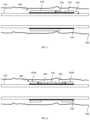
- FIG. 2depicted is a perspective view of an alternative embodiment of a well system 200 including an exemplary operating environment that the apparatuses, systems and methods disclosed herein may be employed.
- the well system 200is similar in many respects to the well stem 100 . Accordingly, like reference numbers have been used to indicate similar, if not identical, features.
- the well system 200in contrast to the well system 100 , includes a wellbore tubular 210 (e.g., liner hanger) extending from the casing 150 into the open hole region 145 .
- the well system 200additionally includes one or more downhole packers 220 located in the open hole region 145 , thereby isolating the various different production zones within the well system 200 .
- the one or more downhole packers 220include the expandable metal configured to expand in response to hydrolysis in accordance with the disclosure. Additionally, the one or more downhole packers 220 are operable to receive a voltage as the expandable metal is expanding in response to wellbore fluid.
- the power(e.g., voltage) is delivered from an electric line 230 , such as a TEC (tubing encapsulated conductor), coupled to an uphole power source.
- the electric line 230may be connected to sensors and actuators downhole.
- the electric line 230may also deliver power (e.g., voltage) to accelerate the chemical reaction of the one or more downhole packers 220 .
- the power (e.g., voltage)can be through a direct connection to the wire or through an inductive coupling or a capacitive coupling.
- the power (e.g., voltage)is delivered from a chemical battery, such as a lithium battery or an alkaline battery.
- the power (e.g., voltage)is delivered from a fluid-flow driven power generator, such as a turbine power generator.
- the opposite voltageis used to delay the initiation of the chemical reaction.
- a positive voltageaccelerates the chemical reaction
- applying a negative voltage to the expandable metalwill inhibit the reaction. This can ensure that the expandable metal does not react (e.g., expand) until the desired time. Additionally, the negative voltage can protect the metal from acid based corrosion.
- FIG. 4A Pourbaix diagram for Mg, Al, and Zn are shown in FIG. 4 .
- a negative voltageis used to delay the reaction of the expandable metal for one period of time and then a positive voltage is used to accelerate the reaction of the expandable metal for a second period of time.
- a power source 530is positioned proximate the expandable metal 520 .
- a first electrode 540couples a first connection of the power source 530 with the expandable metal 520
- a second electrode 545couples a second connection of the power source 530 with the downhole tubular 510 .
- the first connectionis a positive terminal of the power source 530 , thereby causing the expandable metal 520 to function as an anode
- the second connectionis a negative terminal of the power source 530 , thereby causing the downhole tubular 510 to function as a cathode.
- a direct current (DC) power sourcecould be coupled to the expandable metal 520 and the downhole tubular 510 .
- FIG. 6illustrated is an alternative embodiment of a downhole tool 600 .
- the downhole tool 600shares many of the same features as the downhole tool 500 . Accordingly, like reference numbers have been used to illustrate similar, if not identical, features.
- expandable metal 620 a and 620 bare used as both conductive features, for example positioned radially about the downhole tubular 510 .
- a first electrode 640couples a first connection of the power source 530 with the expandable metal 620 a
- a second electrode 645couples a second connection of the power source 530 with the expandable metal 620 b .
- an insulator 650is applied to the expandable metal 620 a and expandable metal 620 b .
- the insulator 650could just be applied to one of the expandable metal 620 a or expandable metal 620 b (e.g., like the anode).
- a non-expandable metalsuch as a plate or a mesh of stainless steel, titanium, or copper, could couple to the second electrode 645 .
- the poweris created from a DC voltage. As shown in FIG. 6 , one of expandable metal 620 a or expandable metal 620 b is the anode and would more rapidly react, while the other of the expandable metal 620 a or expandable metal 620 b is the cathode and would have a delayed reaction. In another embodiment, the power is created from an alternating current (AC) voltage. In this configuration, such as that shown in the embodiment of FIG. 6 , both sections of the expandable metal 620 a and expandable metal 620 b would alternate between being the anode and the cathode, and thus alternate between having a rapid reaction and a delayed reaction.
- ACalternating current
- FIG. 7illustrated is an alternative embodiment of a downhole tool 700 .
- the downhole tool 700shares many of the same features as the downhole tool 500 . Accordingly, like reference numbers have been used to illustrate similar, if not identical, features.
- a power source 730is positioned within the downhole tubular 510 within the wellbore 590 .
- a first electrode 740couples a first connection of the power source 730 with a conductive plate 725 coupled to a slurry of expandable metal particles 720
- a second electrode 745couples a second connection of the power source 730 with a downhole conductive feature 710 .
- the slurry of expandable metal particles 720may be flowed into the downhole tubular 510 in the wellbore 590 .
- the slurry of expandable metal particles 720lands on the conductive plate 725 , which at some point (e.g., either after, before, or substantially simultaneously with the slurry of expandable metal particles 720 landing on the conductive plate 725 ) receives a positive voltage accelerating the expansion thereof.
- the downhole conductive feature 710can be in the fluid (as shown) or can be electrically connected with an oilfield tubular (casing).
- FIG. 8illustrated is yet another alternative embodiment of a downhole tool 800 designed, manufactured and operated according to one aspect of the disclosure.
- the downhole tool 800may be an expandable metal wellbore anchor or an expandable metal packer or seal, among other downhole tools.
- the downhole tool 800includes one or more expandable metal members 820 positioned on a downhole tubular 810 . While the downhole tubular 810 illustrated in FIG. 8 is API pipe, other embodiments may exist wherein another type conveyance is used.
- the one or more expandable metal members 820comprise a metal configured to expand in response to hydrolysis, as discussed in detail above. Furthermore, a combined volume of the one or more expandable metal members should be sufficient to expand to anchor one or more downhole tools within the wellbore in response to the hydrolysis. In one embodiment, the combined volume of the one or more expandable metal members 820 is sufficient to expand to anchor at least about 100,000 Newtons (e.g., about 25,000 lbs.) of weight within the wellbore.
- the combined volume of the one or more expandable metal members 820is sufficient to expand to anchor at least about 200,000 Newtons (e.g., about 50,000 lbs.) of weight within the wellbore, and in yet another embodiment sufficient to expand to anchor at least about 300,000 Newtons (e.g., about 70,000 lbs.) of weight within the wellbore.
- the one or more expandable metal members 820are seals, they may be capable of holding pressures up to about 1000 psi.
- the one or more expandable metal membersare capable of holding pressures up to about 10,000 psi, and in even yet another embodiment up to about 20,000 psi, or more.
- two or more expandable metal members 820are axially positioned along and substantially equally radially spaced about the downhole tubular 810 .
- the two or more expandable metal members 820include openings extending entirely through a wall thickness thereof for accepting a fastener 825 (e.g., a set screw in one embodiment) for fixing to the downhole tubular 810 .
- the two or more expandable metal members 820will expand to engage with the wellbore (e.g., cased region of the wellbore or open hole region of the wellbore) when subjected to a suitable fluid, including a brine based fluid, and thus act as a wellbore anchor and/or wellbore packer.
- a suitable fluidincluding a brine based fluid
- the downhole tool 800includes a power source 830 .
- a first electrode 840is coupled between the one or more expandable metal members 820 and a first connection of the power source 830
- a second electrode 845is coupled between the downhole tubular 810 and a second connection of the power source 830 .
- the power source 830 , and the connections between the power source 830 and the one or more expandable metal members 820may be similar in many respects to the power source 530 discussed above, and thus may be used to accelerate the expansion of the one or more expandable metal members 820 .
- FIG. 9illustrated is yet another alternative embodiment of a downhole tool 900 designed, manufactured and operated according to one aspect of the disclosure.
- the downhole tool 900is similar in many respects to the downhole tool 800 . Accordingly, like reference numerals have been used to reference similar, if not identical, features.
- the downhole tool 900differs from the downhole tool 800 primarily in that it includes two or more spacers 910 radially interleaving the two or more expandable metal members 820 .
- the two or more spacers 910may comprise a variety of different materials and remain within the scope of the disclosure. In the embodiment of FIG. 9 , the two or more spacers 910 do not comprise the metal configured to expand in response to hydrolysis, and thus do not expand.
- the two or more spacers 910could comprise steel.
- FIG. 10illustrated is yet another alternative embodiment of a downhole tool 1000 designed, manufactured and operated according to one aspect of the disclosure.
- the downhole tool 1000is similar in certain respects to the downhole tool 800 . Accordingly, like reference numerals have been used to reference similar, if not identical, features.
- the downhole tool 1000includes a single elongate toroidal expandable metal member 1020 positioned around the downhole tubular 810 .
- the single elongate toroidal expandable metal member 1020may comprise one or more of the expandable metals discussed above.
- the single elongate toroidal expandable metal member 1020need not have a circular opening or circular exterior, and thus could comprise a rectangle, another polygon, or any other suitable shape.
- the single elongate toroidal expandable metal member 1020is held in place on the downhole conveyance 810 using a pair of retaining rings 1030 , for example positioned adjacent a proximal end and a distal end of the single elongate toroidal expandable metal member 1020 .
- the pair of retaining rings 1030does not comprise the metal configured to expand in response to hydrolysis, and moreover include one or more fasteners 825 for holding the single elongate toroidal expandable metal member 1020 in place.
- FIG. 11illustrated is yet another alternative embodiment of a downhole tool 1100 designed, manufactured and operated according to one aspect of the disclosure.
- the downhole tool 1100is similar in many respects to the downhole tool 1000 . Accordingly, like reference numerals have been used to reference similar, if not identical, features.
- the downhole tool 1100includes the single elongate toroidal expandable metal member 1020 positioned around the downhole tubular 810 .
- the downhole tool 1100does not employ retaining rings 1020 .
- the expandable metal downhole tool 1100positions the sets screws 825 directly in openings extending entirely through a wall thickness of the single elongate toroidal expandable metal member 1020 .
- FIG. 12illustrated is yet another alternative embodiment of a downhole tool 1200 designed, manufactured and operated according to one aspect of the disclosure.
- the downhole tool 1200is similar in certain respects to the downhole tool 1000 . Accordingly, like reference numerals have been used to reference similar, if not identical, features.
- the downhole tool 1200includes two or more toroidal expandable metal members 1220 positioned around the downhole tubular 810 . In fact, in the embodiment of FIG. 12 , five toroidal expandable metal members 1220 are used.
- the two or more toroidal expandable metal members 1220may comprise one or more of the expandable metals discussed above.
- the downhole tool 1200 illustrated in FIG. 12additionally includes one or more spacers 1230 axially interleaving the two or more toroidal expandable metal members 1220 .
- the one or more spacers 1230do not comprise the metal configured to expand in response to hydrolysis.
- the downhole tool 1200additionally includes a pair of retaining rings 1030 .
- the pair of retaining rings 1030does not comprise the metal configured to expand in response to hydrolysis, and moreover include one or more fasteners 825 .
- FIG. 13illustrated is yet another alternative embodiment of a downhole tool 1300 designed, manufactured and operated according to one aspect of the disclosure.
- the downhole tool 1300is similar in certain respects to the downhole tool 1100 . Accordingly, like reference numerals have been used to reference similar, if not identical, features.
- the downhole tool 1300additionally includes a swellable rubber member 1310 positioned proximate the one or more expandable metal members 1020 .
- the swellable rubber member 1310in the illustrated embodiment, is configured to swell in response to contact with one or more downhole reactive fluids to pressure seal the wellbore, as well as function as a wellbore anchor.
- the swellable rubber reactive fluidmay be a diesel solution, or other similar water-based solution.
- the swellable rubber member 1310is positioned between a pair of expandable metal members 1020 .
- the swellable rubber member 1310could be placed around at least a portion of the one or more expandable metal members 1020 , and in yet another embodiment could be placed proximate an axial end of the one or more expandable metal members 1020 , among other locations.
- FIG. 14illustrated is yet another alternative embodiment of a downhole tool 1400 designed, manufactured and operated according to one aspect of the disclosure.
- the downhole tool 1400is similar in certain respects to the downhole tool 1100 . Accordingly, like reference numerals have been used to reference similar, if not identical, features.
- the downhole tool 1400additionally includes one or more axial grooves 1410 extending along an entire length thereof.
- the axial groove 1410may comprise a variety of shapes and locations and remain within the scope of the present disclosure.
- the one or more axial grooves 1410may be used to provide fluid flow past the downhole tool 1400 , as well as act as a electric cable (e.g., TEC) or other feature bypass (e.g., no splicing required) for the downhole tool 1400 .
- TECelectric cable
- other feature bypasse.g., no splicing required
- FIG. 15illustrated is yet another alternative embodiment of a downhole tool 1500 designed, manufactured and operated according to one aspect of the disclosure.
- the downhole tool 1500is similar in certain respects to the downhole tool 1100 . Accordingly, like reference numerals have been used to reference similar, if not identical, features.
- the downhole tool 1500additionally includes one or more passageways 1510 (e.g., comprising one or more shunt tubes in one embodiment) extending along an entire length thereof.
- the one or more passageways 1510in accordance with the disclosure, provide fluid flow past the downhole tool 1500 .
- the one or more passageways 1510do not comprise the metal configured to expand in response to hydrolysis, and thus should remain open.
- the one or more passageways 1510are positioned in a wall thickness of the toroidal expandable metal member 1020 , but they could be in other locations, including the axial groove 1410 discussed above with regard to FIG. 14 .
- Element 14wherein the voltage is a negative voltage operable to decelerate the expansion of the expandable metal.
- Element 15wherein the voltage is a negative voltage operable to protect the expandable metal from acid corrosion.
- Element 16wherein the voltage ranges from 0.01 volts to 200 volts.
- Element 17wherein the voltage ranges from 0.5 volts to 10 volts.
- Element 18wherein a current associated with the voltage ranges from 0.05 amps to 5 amps.
- Element 19wherein the downhole conductive feature is conductive tubing positionable within a wellbore.
- Element 20wherein the expandable metal is a first expandable metal feature and the downhole conductive feature is a second expandable metal feature.
- Element 26further including one or more electrical insulators physically separating at least one of the first expandable metal feature and the second expandable from the conductive tubular.
- Element 27wherein the power source is a downhole battery power supply.
- Element 28wherein the power source is a downhole power generator.
- Element 29wherein the power source is an uphole power source, and further including an electric line extending from the uphole power source to the downhole tool.
- Element 31wherein the downhole tool is a downhole tool is a packer.
- Element 32wherein the downhole tool is a downhole anchor.
Landscapes
- Geology (AREA)
- Life Sciences & Earth Sciences (AREA)
- Engineering & Computer Science (AREA)
- Mining & Mineral Resources (AREA)
- Environmental & Geological Engineering (AREA)
- Fluid Mechanics (AREA)
- Physics & Mathematics (AREA)
- General Life Sciences & Earth Sciences (AREA)
- Geochemistry & Mineralogy (AREA)
- Earth Drilling (AREA)
- Electrical Discharge Machining, Electrochemical Machining, And Combined Machining (AREA)
- Electrolytic Production Of Metals (AREA)
- Manufacturing Of Electrical Connectors (AREA)
- Manufacture Of Alloys Or Alloy Compounds (AREA)
Abstract
Description
Mg+2H2O→Mg(OH)2+H2,
where Mg(OH)2is also known as brucite. Another hydration reaction uses aluminum hydrolysis. The reaction forms a material known as Gibbsite, bayerite, and norstrandite, depending on form. The hydration reaction for aluminum is:
Al+3H2O→Al(OH)3+3/2H2.
Ca+2H2O→Ca(OH)2+H2,
Where Ca(OH)2is known as portlandite and is a common hydrolysis product of Portland cement. Magnesium hydroxide and calcium hydroxide are considered to be relatively insoluble in water. Aluminum hydroxide can be considered an amphoteric hydroxide, which has solubility in strong acids or in strong bases.
Claims (20)
Priority Applications (12)
| Application Number | Priority Date | Filing Date | Title |
|---|---|---|---|
| AU2021209133AAU2021209133B2 (en) | 2020-01-17 | 2021-01-18 | Voltage to accelerate/decelerate expandable metal |
| GB2400949.0AGB2624125B (en) | 2020-01-17 | 2021-01-18 | Voltage to accelerate/decelerate expandable metal |
| MX2022007448AMX2022007448A (en) | 2020-01-17 | 2021-01-18 | Voltage to accelerate/decelerate expandable metal. |
| GB2400950.8AGB2624126B (en) | 2020-01-17 | 2021-01-18 | Voltage to accelerate/decelerate expandable metal |
| PCT/US2021/013825WO2021146684A1 (en) | 2020-01-17 | 2021-01-18 | Voltage to accelerate/decelerate expandable metal |
| CA3160788ACA3160788A1 (en) | 2020-01-17 | 2021-01-18 | Voltage to accelerate/decelerate expandable metal |
| NO20220612ANO20220612A1 (en) | 2020-01-17 | 2021-01-18 | Voltage to accelerate/decelerate expandable metal |
| US17/151,468US12352127B2 (en) | 2020-01-17 | 2021-01-18 | Voltage to accelerate/decelerate expandable metal |
| BR112022011008ABR112022011008A2 (en) | 2020-01-17 | 2021-01-18 | METHOD FOR LAYING A BOTTOM TOOL, BOTTOM TOOL AND WELL SYSTEM |
| GB2207606.1AGB2605062B (en) | 2020-01-17 | 2021-01-18 | Voltage to accelerate/decelerate expandable metal |
| DKPA202270318ADK202270318A1 (en) | 2020-01-17 | 2022-06-14 | Voltage to accelerate/decelerate expandable metal |
| US19/232,491US20250305382A1 (en) | 2020-01-17 | 2025-06-09 | Voltage to accelerate/decelerate expandable metal |
Applications Claiming Priority (2)
| Application Number | Priority Date | Filing Date | Title |
|---|---|---|---|
| US202062962901P | 2020-01-17 | 2020-01-17 | |
| US17/151,468US12352127B2 (en) | 2020-01-17 | 2021-01-18 | Voltage to accelerate/decelerate expandable metal |
Related Child Applications (1)
| Application Number | Title | Priority Date | Filing Date |
|---|---|---|---|
| US19/232,491DivisionUS20250305382A1 (en) | 2020-01-17 | 2025-06-09 | Voltage to accelerate/decelerate expandable metal |
Publications (2)
| Publication Number | Publication Date |
|---|---|
| US20210222510A1 US20210222510A1 (en) | 2021-07-22 |
| US12352127B2true US12352127B2 (en) | 2025-07-08 |
Family
ID=76857947
Family Applications (2)
| Application Number | Title | Priority Date | Filing Date |
|---|---|---|---|
| US17/151,468Active2042-01-25US12352127B2 (en) | 2020-01-17 | 2021-01-18 | Voltage to accelerate/decelerate expandable metal |
| US19/232,491PendingUS20250305382A1 (en) | 2020-01-17 | 2025-06-09 | Voltage to accelerate/decelerate expandable metal |
Family Applications After (1)
| Application Number | Title | Priority Date | Filing Date |
|---|---|---|---|
| US19/232,491PendingUS20250305382A1 (en) | 2020-01-17 | 2025-06-09 | Voltage to accelerate/decelerate expandable metal |
Country Status (9)
| Country | Link |
|---|---|
| US (2) | US12352127B2 (en) |
| AU (1) | AU2021209133B2 (en) |
| BR (1) | BR112022011008A2 (en) |
| CA (1) | CA3160788A1 (en) |
| DK (1) | DK202270318A1 (en) |
| GB (3) | GB2605062B (en) |
| MX (1) | MX2022007448A (en) |
| NO (1) | NO20220612A1 (en) |
| WO (1) | WO2021146684A1 (en) |
Families Citing this family (4)
| Publication number | Priority date | Publication date | Assignee | Title |
|---|---|---|---|---|
| US20230160272A1 (en)* | 2021-11-22 | 2023-05-25 | Baker Hughes Oilfield Operations Llc | Anchor for tool, method for managing a borehole, and system |
| US12345120B2 (en) | 2022-05-10 | 2025-07-01 | Halliburton Energy Services, Inc. | Fast-acting swellable downhole seal |
| US12305459B2 (en)* | 2022-06-15 | 2025-05-20 | Halliburton Energy Services, Inc. | Sealing/anchoring tool employing an expandable metal circlet |
| WO2025096612A1 (en)* | 2023-10-31 | 2025-05-08 | Saudi Arabian Oil Company | Systems and methods for anchoring a sub-surface completion unit in a wellbore |
Citations (285)
| Publication number | Priority date | Publication date | Assignee | Title |
|---|---|---|---|---|
| US1525740A (en) | 1921-09-12 | 1925-02-10 | Ernest E Howard | Substructure construction |
| US2075912A (en) | 1935-03-28 | 1937-04-06 | Gray Tool Co | Packer |
| US2590931A (en) | 1949-02-11 | 1952-04-01 | Sperry Sun Well Surveying Co | Chemically heated paraffin knife |
| US2743781A (en) | 1952-08-25 | 1956-05-01 | Guiberson Corp | Hydraulic anchor tool |
| US2865454A (en) | 1956-07-02 | 1958-12-23 | Shell Dev | Oil well fishing apparatus and method |
| US3206536A (en) | 1963-04-24 | 1965-09-14 | Alfred M Goodloe | Expanded metal rf radiation shielding gasket |
| US3371716A (en) | 1965-10-23 | 1968-03-05 | Schlumberger Technology Corp | Bridge plug |
| US3616354A (en) | 1964-04-17 | 1971-10-26 | Gordon Ian Russell | Method for installing cathodic protection |
| US3706125A (en) | 1970-08-10 | 1972-12-19 | John P Hopkins Co | Pipe line construction method |
| EP0015726A1 (en) | 1979-03-02 | 1980-09-17 | Roger Dale Crooks | Method relating to the pumping of fluid along a tubular structure in a bore of a well and tubular component for use in such structure |
| US4270608A (en) | 1979-12-27 | 1981-06-02 | Halliburton Company | Method and apparatus for gravel packing multiple zones |
| US4424859A (en) | 1981-11-04 | 1984-01-10 | Sims Coleman W | Multi-channel fluid injection system |
| US4424861A (en) | 1981-10-08 | 1984-01-10 | Halliburton Company | Inflatable anchor element and packer employing same |
| US4442908A (en) | 1980-07-12 | 1984-04-17 | Preussag Aktiengesellschaft | Tool for drilling curved sections of well holes |
| US4446932A (en) | 1981-04-24 | 1984-05-08 | Petro-Drive, Inc. | Hydrostatic shear pin |
| US4457379A (en) | 1982-02-22 | 1984-07-03 | Baker Oil Tools, Inc. | Method and apparatus for opening downhole flapper valves |
| US4527815A (en) | 1982-10-21 | 1985-07-09 | Mobil Oil Corporation | Use of electroless nickel coating to prevent galling of threaded tubular joints |
| US4977636A (en) | 1989-08-30 | 1990-12-18 | King John B | Pile supported bridge assembly |
| US4979585A (en) | 1989-10-02 | 1990-12-25 | Halliburton Logging Services, Inc. | Compound suspension linkage |
| US5139274A (en) | 1989-03-11 | 1992-08-18 | Oseman Gavin S | Seal for a hydraulic ram |
| US5220959A (en) | 1991-09-24 | 1993-06-22 | The Gates Rubber Company | Gripping inflatable packer |
| US5424139A (en) | 1994-01-10 | 1995-06-13 | Lydall, Inc. | Metal heat insulator |
| US5492173A (en) | 1993-03-10 | 1996-02-20 | Halliburton Company | Plug or lock for use in oil field tubular members and an operating system therefor |
| US5517981A (en) | 1994-06-21 | 1996-05-21 | The United States Of America As Represented By The Secretary Of The Army | Water-activated chemical heater with suppressed hydrogen |
| US5662341A (en) | 1996-03-19 | 1997-09-02 | Halliburton Company | Metal-to-metal seal assembly for oil and gas well production apparatus |
| US5667015A (en) | 1995-02-03 | 1997-09-16 | Bj Services Company | Well barrier |
| US5803173A (en) | 1996-07-29 | 1998-09-08 | Baker Hughes Incorporated | Liner wiper plug apparatus and method |
| EP0869257A2 (en) | 1997-03-31 | 1998-10-07 | Halliburton Energy Services, Inc. | Primary well cementing |
| EP0940558A1 (en) | 1998-03-06 | 1999-09-08 | Shell Internationale Researchmaatschappij B.V. | Electrical heater |
| US6089320A (en) | 1997-10-10 | 2000-07-18 | Halliburton Energy Services, Inc. | Apparatus and method for lateral wellbore completion |
| US6106024A (en) | 1998-06-04 | 2000-08-22 | Cooper Cameron Corporation | Riser joint and apparatus for its assembly |
| WO2002002900A2 (en) | 2000-06-30 | 2002-01-10 | Watherford/Lamb, Inc. | Apparatus and method to complete a multilateral junction |
| KR20020014619A (en) | 2000-08-18 | 2002-02-25 | 전상율 | The construction method of landfill in soft soil using the horeizontal expansion pile |
| US20020088616A1 (en) | 2000-07-11 | 2002-07-11 | Swor Loren C. | High temperature high pressure retrievable packer with barrel slip |
| JP2003090037A (en) | 2000-12-28 | 2003-03-28 | Jun Nishiwaki | Pile construction method |
| US20030132001A1 (en) | 2000-08-17 | 2003-07-17 | Wilson James Brian | Flow control device |
| US20030164237A1 (en) | 2002-03-01 | 2003-09-04 | Butterfield Charles A. | Method, apparatus and system for selective release of cementing plugs |
| US20030164236A1 (en) | 2000-06-30 | 2003-09-04 | Thornton John Thomas Oliver | Downhole tools |
| JP2003293354A (en) | 2002-02-04 | 2003-10-15 | Geotop Corp | Construction method of foundation ground |
| US20030205377A1 (en) | 2002-05-06 | 2003-11-06 | National Oilwell, L.P. | Packer retriever |
| JP2004169303A (en) | 2002-11-18 | 2004-06-17 | Geotop Corp | Ready-made piles and their construction methods |
| US20040194970A1 (en)* | 2003-04-07 | 2004-10-07 | Eatwell William Donald | Expandable seal member with shape memory alloy |
| US6840325B2 (en) | 2002-09-26 | 2005-01-11 | Weatherford/Lamb, Inc. | Expandable connection for use with a swelling elastomer |
| WO2005022012A1 (en) | 2003-08-29 | 2005-03-10 | Caledyne Limited | Improved seal |
| US20050051333A1 (en) | 2003-09-04 | 2005-03-10 | Weber James L. | Wiper plug with packer |
| US20050061369A1 (en) | 2003-04-15 | 2005-03-24 | De Almeida Alcino Resende | Mandrel for a gas lift valve |
| US20050072576A1 (en) | 2003-10-03 | 2005-04-07 | Henriksen Knut H. | Mud flow back valve |
| US20050093250A1 (en) | 2003-11-05 | 2005-05-05 | Santi Nestor J. | High-strength sealed connection for expandable tubulars |
| US6907930B2 (en) | 2003-01-31 | 2005-06-21 | Halliburton Energy Services, Inc. | Multilateral well construction and sand control completion |
| US6942039B2 (en) | 2002-04-08 | 2005-09-13 | Team Oil Tools, Llc | Flapper valve and associated method for single trip retrieval of packer tools |
| US20050199401A1 (en) | 2004-03-12 | 2005-09-15 | Schlumberger Technology Corporation | System and Method to Seal Using a Swellable Material |
| WO2006045794A1 (en) | 2004-10-27 | 2006-05-04 | Shell Internationale Research Maatschappij B.V. | Sealing of a wellbore device in a tubular element |
| US20060144591A1 (en) | 2004-12-30 | 2006-07-06 | Chevron U.S.A. Inc. | Method and apparatus for repair of wells utilizing meltable repair materials and exothermic reactants as heating agents |
| US7104322B2 (en) | 2003-05-20 | 2006-09-12 | Weatherford/Lamb, Inc. | Open hole anchor and associated method |
| US20060272806A1 (en) | 2005-01-31 | 2006-12-07 | Wilkie Arnold E | Swelling packer with overlapping petals |
| US7152687B2 (en) | 2003-11-06 | 2006-12-26 | Halliburton Energy Services, Inc. | Expandable tubular with port valve |
| EP1757770A1 (en) | 2005-08-25 | 2007-02-28 | Services Petroliers Schlumberger (Sps) | Method and apparatus to set a plug in a wellbore |
| WO2007047089A1 (en) | 2005-10-21 | 2007-04-26 | Halliburton Energy Services, Inc. | High pressure d-tube with enhanced through tube access |
| US20070089910A1 (en) | 2003-01-09 | 2007-04-26 | Hewson James A | Method of forming a bore |
| US20070095532A1 (en) | 2003-06-30 | 2007-05-03 | Philip Head | Apparatus and method for sealing a wellbore |
| US20070137826A1 (en) | 2001-06-05 | 2007-06-21 | Bosma Martin G R | Creating a well abandonment plug |
| US20070144734A1 (en) | 2005-03-30 | 2007-06-28 | Xu Zheng R | Inflatable packers |
| US20070151724A1 (en) | 2006-01-05 | 2007-07-05 | Schlumberger Technology Corporation | System and Method for Isolating a Wellbore Region |
| US20070163781A1 (en) | 2005-05-06 | 2007-07-19 | Bj Services Company | Multi-zone, single trip well completion system and methods of use |
| US20070221387A1 (en) | 2006-03-21 | 2007-09-27 | Warren Michael Levy | Expandable downhole tools and methods of using and manufacturing same |
| US20070246213A1 (en) | 2006-04-20 | 2007-10-25 | Hailey Travis T Jr | Gravel packing screen with inflow control device and bypass |
| US20070267824A1 (en) | 2006-05-19 | 2007-11-22 | Baugh John L | Seal and slip assembly for expandable downhole tools |
| US20070277979A1 (en) | 2006-06-06 | 2007-12-06 | Halliburton Energy Services | Downhole wellbore tools having deteriorable and water-swellable components thereof and methods of use |
| US7322408B2 (en) | 2002-12-09 | 2008-01-29 | Specialised Petroleum Services Group Ltd. | Downhole tool with actuable barrier |
| US20080047708A1 (en) | 2006-06-24 | 2008-02-28 | Spencer Homer L | Method and apparatus for plugging perforations |
| US7347274B2 (en) | 2004-01-27 | 2008-03-25 | Schlumberger Technology Corporation | Annular barrier tool |
| US7350590B2 (en) | 2002-11-05 | 2008-04-01 | Weatherford/Lamb, Inc. | Instrumentation for a downhole deployment valve |
| EP1910728A1 (en) | 2005-07-29 | 2008-04-16 | Viega GmbH & Co. KG | Connection element for producing a fluid-tight screw connection, and method for the production thereof |
| GB2444060A (en) | 2006-11-21 | 2008-05-28 | Swelltec Ltd | Swellable downhole apparatus |
| US20080135249A1 (en)* | 2006-12-07 | 2008-06-12 | Fripp Michael L | Well system having galvanic time release plug |
| US20080149351A1 (en) | 2006-12-20 | 2008-06-26 | Schlumberger Technology Corporation | Temporary containments for swellable and inflatable packer elements |
| US7402277B2 (en) | 2006-02-07 | 2008-07-22 | Exxonmobil Research And Engineering Company | Method of forming metal foams by cold spray technique |
| US20080290603A1 (en) | 2007-05-24 | 2008-11-27 | Baker Hughes Incorporated | Swellable material and method |
| US20090014173A1 (en) | 2005-03-04 | 2009-01-15 | Iain Macleod | Well bore anchors |
| US20090084555A1 (en) | 2005-06-15 | 2009-04-02 | Paul Bernard Lee | Novel activating mechanism for controlling the operation of a downhole tool |
| US20090102133A1 (en) | 2007-10-18 | 2009-04-23 | Baker Hughes Incorporated | Downhole tubular sealing system |
| US20090159278A1 (en) | 2006-12-29 | 2009-06-25 | Pierre-Yves Corre | Single Packer System for Use in Heavy Oil Environments |
| US20090200028A1 (en) | 2008-02-08 | 2009-08-13 | Swellfix Bv | Wellbore delivery apparatus |
| US7578043B2 (en) | 2002-07-06 | 2009-08-25 | Weatherford/Lamb, Inc. | Coupling tubulars |
| US20090250228A1 (en) | 2008-04-03 | 2009-10-08 | Schlumberger Technology Corporation | Well packers and control line management |
| US20090250227A1 (en) | 2008-04-02 | 2009-10-08 | Halliburton Energy Services, Inc. | A System And Method For Plugging A Side Pocket Mandrel Using A Swelling Plug |
| US20090321087A1 (en) | 2008-06-27 | 2009-12-31 | Electrical/Electronic Mechanical Industrial Equipment Ltd. | Expandable plug |
| US7673688B1 (en) | 2008-09-09 | 2010-03-09 | Halliburton Energy Services, Inc. | Casing wiping dart with filtering layer |
| US7677303B2 (en) | 2008-04-14 | 2010-03-16 | Baker Hughes Incorporated | Zero-relaxation packer setting lock system |
| US20100072711A1 (en) | 2008-09-19 | 2010-03-25 | Baker Hughes Incorporated | Expandable metal-to-metal seal |
| US20100078173A1 (en) | 2008-09-29 | 2010-04-01 | Frank's International, Inc. | Downhole device actuator and method |
| US7696275B2 (en) | 2003-11-20 | 2010-04-13 | Halliburton Energy Services, Inc. | Downhole seal element formed from a nanocomposite material |
| US20100096143A1 (en) | 2008-10-20 | 2010-04-22 | Tesco Corporation (Us) | Method for Installing Wellbore String Devices |
| US20100108148A1 (en) | 2008-10-31 | 2010-05-06 | Schlumberger Technology Corporation | Utilizing swellable materials to control fluid flow |
| US20100122819A1 (en) | 2008-11-17 | 2010-05-20 | Baker Hughes Incorporated | Inserts with Swellable Elastomer Seals for Side Pocket Mandrels |
| US20100155083A1 (en) | 2008-12-18 | 2010-06-24 | Baker Hughes Incorporated | Open-hole anchor for whipstock system |
| US20100225107A1 (en) | 2006-02-17 | 2010-09-09 | Norsk Hydro Asa | Gas Tight Tubular Joint or Connection |
| US20100257913A1 (en) | 2009-04-13 | 2010-10-14 | Enventure Global Technology, Llc | Resilient Anchor |
| US20100307737A1 (en) | 2007-10-29 | 2010-12-09 | Jone Mellemstrand | Packer with Ribs |
| US20110061876A1 (en) | 2008-12-16 | 2011-03-17 | Mark Johnson | Method and Apparatus for Cementing a Liner in a Borehole Using a Tubular Member Having an Obstruction |
| US20110098202A1 (en)* | 2008-04-28 | 2011-04-28 | Simon James | Swellable compositions for borehole applications |
| US7963321B2 (en) | 2009-05-15 | 2011-06-21 | Tam International, Inc. | Swellable downhole packer |
| US20110147014A1 (en) | 2009-12-21 | 2011-06-23 | Schlumberger Technology Corporation | Control swelling of swellable packer by pre-straining the swellable packer element |
| US7996945B2 (en) | 2003-07-08 | 2011-08-16 | Rutgers, The State University Of New Jersey | Use of recycled plastics for structural building forms |
| US20120018143A1 (en) | 2010-07-23 | 2012-01-26 | Weatherford/Lamb, Inc. | Swellable Packer Anchors |
| US8109339B2 (en) | 2009-08-21 | 2012-02-07 | Baker Hughes Incorporated | Zero backlash downhole setting tool and method |
| US20120048561A1 (en) | 2010-09-01 | 2012-03-01 | Halliburton Energy Services, Inc. | Downhole adjustable inflow control device for use in a subterranean well |
| US20120048623A1 (en) | 2009-05-07 | 2012-03-01 | Vam Drilling France | Holding device insertable into the central bore of a tubular drill string component, and corresponding tubular drill string component |
| US20120049462A1 (en) | 2009-02-14 | 2012-03-01 | Malcolm Pitman | Connector seal |
| US20120048531A1 (en) | 2009-04-27 | 2012-03-01 | Halliburton Energy Services, Inc. | Thermal Component Temperature Management System and Method |
| EP2447466A2 (en) | 2010-10-26 | 2012-05-02 | Weatherford/Lamb, Inc. | Downhole flow device with erosion resistant and pressure assisted metal seal |
| US20120168147A1 (en) | 2011-01-05 | 2012-07-05 | Bowersock Justin C | Overshot with Dynamic Seal Feature |
| US20120175134A1 (en) | 2011-01-11 | 2012-07-12 | Schlumberger Technology Corporation | Oilfield apparatus and method comprising swellable elastomers |
| US8225861B2 (en) | 2009-03-11 | 2012-07-24 | Baker Hughes Incorporated | Sealing feed through lines for downhole swelling packers |
| US8266751B2 (en) | 2009-12-10 | 2012-09-18 | Yidong He | Method to compress prefabricated deck units by tensioning supporting girders |
| WO2012125660A2 (en) | 2011-03-14 | 2012-09-20 | Smith International Inc. | Dual wiper plug system |
| EP2501890A2 (en) | 2009-11-20 | 2012-09-26 | Halliburton Energy Services, Inc. | Swellable connection system and method of using the same |
| US20120273236A1 (en) | 2011-04-27 | 2012-11-01 | Varadaraju Gandikota | Expandable open-hole anchor |
| US20130048289A1 (en) | 2011-08-30 | 2013-02-28 | Baker Hughes Incorporated | Sealing system, method of manufacture thereof and articles comprising the same |
| US20130056209A1 (en) | 2011-09-06 | 2013-03-07 | Baker Hughes Incorporated | Swelling Acceleration Using Inductively Heated and Embedded Particles in a Subterranean Tool |
| US20130056207A1 (en) | 2011-09-02 | 2013-03-07 | Baker Hughes Incorporated | Downhole sealing system using cement activated material and method of downhole sealing |
| US20130081815A1 (en) | 2011-09-30 | 2013-04-04 | Baker Hughes Incorporated | Enhancing Swelling Rate for Subterranean Packers and Screens |
| US8430176B2 (en) | 2009-08-21 | 2013-04-30 | Baker Hughes Incorporated | Zero backlash downhole setting tool and method |
| US8453736B2 (en) | 2010-11-19 | 2013-06-04 | Baker Hughes Incorporated | Method and apparatus for stimulating production in a wellbore |
| US8459367B2 (en) | 2008-03-04 | 2013-06-11 | Swelltec Limited | Swellable packer having a cable conduit |
| US20130153236A1 (en) | 2011-12-20 | 2013-06-20 | Baker Hughes Incorporated | Subterranean Tool Actuation Using a Controlled Electrolytic Material Trigger |
| US20130152824A1 (en) | 2011-12-16 | 2013-06-20 | James B. Crews | Electrolytic composite materials |
| US8469084B2 (en) | 2009-07-15 | 2013-06-25 | Schlumberger Technology Corporation | Wireless transfer of power and data between a mother wellbore and a lateral wellbore |
| US20130161006A1 (en) | 2011-12-27 | 2013-06-27 | Agathe Robisson | Downhole sealing using settable material in an elastic membrane |
| US20130186615A1 (en) | 2010-10-07 | 2013-07-25 | Jorgen Hallunbæk | Annular barrier |
| US20130192853A1 (en) | 2010-10-06 | 2013-08-01 | Packers Plus Energy Services Inc. | Wellbore packer back-up ring assembly, packer and method |
| CA2820742A1 (en) | 2013-07-04 | 2013-09-20 | IOR Canada Ltd. | Improved hydrocarbon recovery process exploiting multiple induced fractures |
| US20130292117A1 (en) | 2012-05-04 | 2013-11-07 | Schlumberger Technology Corporation | Compliant sand screen |
| US8579024B2 (en) | 2010-07-14 | 2013-11-12 | Team Oil Tools, Lp | Non-damaging slips and drillable bridge plug |
| CN203308412U (en) | 2013-06-09 | 2013-11-27 | 中国石油化工股份有限公司 | Selective and drillable anchoring mechanism for packer |
| US20140026335A1 (en) | 2012-07-27 | 2014-01-30 | OCCI, Inc. | System and method for bridge replacement |
| US20140034308A1 (en) | 2012-08-03 | 2014-02-06 | Halliburton Energy Services, Inc. | Method and apparatus for remote zonal stimulation with fluid loss device |
| US20140051612A1 (en) | 2012-08-14 | 2014-02-20 | Baker Hughes Incorporated | Swellable article |
| US8684096B2 (en) | 2009-04-02 | 2014-04-01 | Key Energy Services, Llc | Anchor assembly and method of installing anchors |
| US8794330B2 (en) | 2010-11-01 | 2014-08-05 | Completion Tool Developments, Inc. | Apparatus for single-trip time progressive wellbore treatment |
| US8807209B2 (en) | 2007-05-31 | 2014-08-19 | Baker Hughes Incorporated | Swellable material and method |
| US20140262352A1 (en) | 2013-03-14 | 2014-09-18 | Weatherford/Lamb, Inc. | Cable By-Pass for Spooled Cables |
| WO2014182301A1 (en) | 2013-05-09 | 2014-11-13 | Halliburton Energy Services, Inc. | Swellable packer with reinforcement and anti-extrusion features |
| US8894070B2 (en) | 2008-02-04 | 2014-11-25 | Halliburton Energy Services, Inc. | Energized composite metal to metal seal |
| WO2014193042A1 (en) | 2013-05-29 | 2014-12-04 | 한국에너지기술연구원 | Pipe for heat energy |
| US20150021049A1 (en) | 2013-07-22 | 2015-01-22 | Tam International, Inc. | Swellable casing anchor |
| US20150075768A1 (en) | 2010-01-15 | 2015-03-19 | Halliburton Energy Services, Inc. | Well tools operable via thermal expansion resulting from reactive materials |
| US9004173B2 (en) | 2011-05-10 | 2015-04-14 | Baker Hughes Incorporated | Cement wiper plug with size changing feature |
| US20150101813A1 (en) | 2013-10-15 | 2015-04-16 | Baker Hughes Incorporated | Methods for hanging liner from casing and articles derived therefrom |
| US20150113913A1 (en) | 2012-05-29 | 2015-04-30 | Ajou University Industry-Academic Cooperation Foundation | Hollow structure, and preparation method thereof |
| WO2015069886A2 (en) | 2013-11-06 | 2015-05-14 | Weatherford/Lamb, Inc. | Structural insert for composite bridge plug |
| WO2015099909A1 (en) | 2013-12-23 | 2015-07-02 | Baker Hughes Incorporated | Conformable devices using shape memory alloys for downhole applications |
| US20150184486A1 (en) | 2013-10-31 | 2015-07-02 | Jeffrey Stephen Epstein | Sacrificial isolation ball for fracturing subsurface geologic formations |
| US20150233190A1 (en) | 2012-10-12 | 2015-08-20 | Schlumberger Technology Corporation | Multilateral Y-Block System |
| US20150275587A1 (en) | 2012-10-12 | 2015-10-01 | Schlumberger Technology Corporation | Non-threaded tubular connection |
| JP2015175449A (en) | 2014-03-17 | 2015-10-05 | 東亜グラウト工業株式会社 | Repair method for existing pipe parts |
| US20150337615A1 (en) | 2013-10-31 | 2015-11-26 | Jeffrey Stephen Epstein | Isolation member and isolation member seat for fracturing subsurface geologic formations |
| WO2015183277A1 (en) | 2014-05-29 | 2015-12-03 | Halliburton Energy Services, Inc. | Packer assembly with thermal expansion buffers |
| US20150345248A1 (en) | 2012-12-20 | 2015-12-03 | Bisn Tec Ltd | Apparatus for use in well abandonment |
| US9217311B2 (en) | 2012-11-05 | 2015-12-22 | Baker Hughes Incorporated | Flapper valve and method of valving a tubular |
| US20150369003A1 (en) | 2012-12-19 | 2015-12-24 | Schlumberger Technology Corporation | Downhole Valve Utilizing Degradable Material |
| US20150368990A1 (en) | 2014-06-18 | 2015-12-24 | Portable Composite Structures, Inc. | Centralizer with collaborative spring force |
| WO2016000068A1 (en) | 2014-07-02 | 2016-01-07 | IOR Canada Ltd. | Multi-flow pipe and pipe couplings therefor for use in fracture flow hydrocarbon recovery processes |
| US20160024896A1 (en) | 2013-03-04 | 2016-01-28 | Halliburton Energy Services, Inc | Abandonment and containment system for gas wells |
| US20160024902A1 (en) | 2014-07-22 | 2016-01-28 | Schlumberger Technology Corporation | Methods and cables for use in fracturing zones in a well |
| US9249904B2 (en) | 2009-08-21 | 2016-02-02 | Titeflex Corporation | Energy dissipative tubes and methods of fabricating and installing the same |
| US9279295B2 (en) | 2012-06-28 | 2016-03-08 | Weatherford Technology Holdings, Llc | Liner flotation system |
| US20160138559A1 (en) | 2014-11-13 | 2016-05-19 | Jerome A. Bauer | Automatic height adjusting paddle wheel |
| US20160138359A1 (en) | 2014-11-17 | 2016-05-19 | Baker Hughes Incorporated | Swellable compositions, articles formed therefrom, and methods of manufacture thereof |
| US20160137912A1 (en) | 2012-12-10 | 2016-05-19 | Powdermet, Inc. | Structural Expandable Materials |
| US9347272B2 (en) | 2002-08-30 | 2016-05-24 | Technology Ventures International Limited | Method and assembly for forming a supported bore using a first and second drill bit |
| US20160145968A1 (en)* | 2013-06-28 | 2016-05-26 | Schlumberger Technology Corporation | Smart Cellular Structures For Composite Packer And Mill-Free Bridgeplug Seals Having Enhanced Pressure Rating |
| US20160145488A1 (en) | 2013-03-14 | 2016-05-26 | Lawrence Livermore National Security, Llc | Encapsulated proppants |
| US9353606B2 (en) | 2010-11-16 | 2016-05-31 | Darcy Technologies Limited | Downhole method and apparatus |
| US20160177668A1 (en) | 2014-08-15 | 2016-06-23 | Thru Tubing Solutions, Inc. | Flapper valve tool |
| US20160194936A1 (en) | 2015-01-06 | 2016-07-07 | Baker Hughes Incorporated | Completion assembly with bypass for reversing valve |
| US9393601B2 (en) | 2013-05-31 | 2016-07-19 | Baker Hughes Incorporated | Convertible wiping device |
| US20160208569A1 (en) | 2013-09-30 | 2016-07-21 | Swellfix B.V. | Sealing insert and method |
| CN205422632U (en) | 2016-03-16 | 2016-08-03 | 上海尊优自动化设备有限公司 | Cage anchoring slips and packer slip mechanism |
| US20160273312A1 (en) | 2014-07-16 | 2016-09-22 | Halliburton Energy Services, Inc. | Multilateral junction with mechanical stiffeners |
| WO2016171666A1 (en) | 2015-04-21 | 2016-10-27 | Schlumberger Canada Limited | Swellable component for a downhole tool |
| US20160319633A1 (en) | 2014-12-02 | 2016-11-03 | Schlumberger Technology Corporation | Methods of deployment for eutectic isolation tools to ensure wellbore plugs |
| US20160326830A1 (en) | 2013-04-12 | 2016-11-10 | Welltec A/S | A downhole expandable tubular |
| US20160326849A1 (en) | 2013-12-30 | 2016-11-10 | Darcy Technologies Limited | Downhole apparatus |
| US20160333187A1 (en) | 2015-05-14 | 2016-11-17 | LiquiGlide Inc. | Systems and methods for controlling the degradation of degradable materials |
| US9534460B2 (en) | 2014-08-15 | 2017-01-03 | Thru Tubing Solutions, Inc. | Flapper valve tool |
| US20170015824A1 (en) | 2015-07-14 | 2017-01-19 | Weir Slurry Group, Inc. | Swellable rubber compositions |
| US20170022778A1 (en) | 2014-04-16 | 2017-01-26 | Halliburton Energy Services, Inc. | Time-delay coating for dissolvable wellbore isolation devices |
| EP3144018A1 (en) | 2014-05-13 | 2017-03-22 | Jiangsu Fengyuan Medical Devices Co., Ltd. | Method for preparing surface coating with reduced degradation rate of biodegradable magnesium alloy vascular stent |
| US9611715B1 (en) | 2012-09-12 | 2017-04-04 | Alaskan Energy Resources, Inc. | Isolation liner incorporating a drill pipe with swell packers |
| US20170107419A1 (en) | 2014-05-30 | 2017-04-20 | Schlumberger Technology Corporation | Degradable heat treatable components |
| US20170107794A1 (en) | 2014-07-10 | 2017-04-20 | Halliburton Energy Services Inc. | Multilateral junction fitting for intelligent completion of well |
| US20170113275A1 (en) | 2014-05-30 | 2017-04-27 | Schlumberger Technology Corporation | Degradable powder blend |
| US9644459B2 (en) | 2010-07-28 | 2017-05-09 | Packers Plus Energy Services Inc. | Wellbore lateral liner placement system |
| US20170159401A1 (en) | 2014-07-11 | 2017-06-08 | Saltel Industries | Expandable tubular element bearing one or more swelling seals |
| WO2017100417A1 (en) | 2015-12-08 | 2017-06-15 | Ensign-Bickford Aerospace & Defense Company | Destructible casing segmentation device and method for use |
| US20170175488A1 (en) | 2015-12-21 | 2017-06-22 | Packers Plus Energy Services Inc. | Indexing dart system and method for wellbore fluid treatment |
| US20170175487A1 (en) | 2015-12-21 | 2017-06-22 | Vanguard Completions Ltd. | Downhole drop plugs, downhole valves, frac tools, and related methods of use |
| US20170191342A1 (en) | 2011-02-16 | 2017-07-06 | Weatherford Technology Holdings, Llc | Anchoring seal |
| US20170198191A1 (en) | 2011-05-11 | 2017-07-13 | Schlumberger Technology Corporation | Methods of zonal isolation and treatment diversion |
| US9708880B2 (en) | 2012-06-08 | 2017-07-18 | Halliburton Energy Services, Inc. | Swellable packer with enhanced anchoring and/or sealing capability |
| EP3196402A1 (en) | 2016-01-22 | 2017-07-26 | Shell Internationale Research Maatschappij B.V. | Plugging to-be-abandoned wellbores in the earth |
| US9732578B2 (en) | 2007-08-25 | 2017-08-15 | Swellfix B.V. | Downhole sealing assembly with swellable seal |
| US20170234103A1 (en) | 2014-04-02 | 2017-08-17 | Magnum Oil Tools International, Ltd. | Dissolvable downhole tools comprising both degradable polymer acid and degradable metal alloy elements |
| US9765595B2 (en) | 2011-10-11 | 2017-09-19 | Packers Plus Energy Services Inc. | Wellbore actuators, treatment strings and methods |
| US20170306714A1 (en) | 2014-10-03 | 2017-10-26 | Qinterra Technologies As | Wireline Operated Dump Bailer And Method For Unloading Of Material In A Well |
| US20170314372A1 (en) | 2016-04-29 | 2017-11-02 | Randy C. Tolman | System and Method for Autonomous Tools |
| US20170350237A1 (en) | 2016-06-03 | 2017-12-07 | Schlumberger Technology Corporation | Methods and appartus for remote actuation of a downhole device in a wellbore |
| US20170356266A1 (en) | 2014-12-18 | 2017-12-14 | Halliburton Energy Services, Inc. | Casing segment methods and systems with time control of degradable plugs |
| US20180023366A1 (en) | 2016-01-06 | 2018-01-25 | Baker Hughes, A Ge Company, Llc | Slotted Backup Ring Assembly |
| US20180023362A1 (en) | 2015-03-26 | 2018-01-25 | Halliburton Energy Services, Inc. | Multifunction downhole plug |
| US20180038193A1 (en) | 2015-04-01 | 2018-02-08 | Halliburton Energy Services, Inc. | Degradable expanding wellbore isolation device |
| US20180078998A1 (en) | 2014-02-21 | 2018-03-22 | Terves Inc. | Self-Actuating Device For Centralizing an Object |
| US20180081468A1 (en) | 2012-03-07 | 2018-03-22 | Darcy Technologies Limited | Downhole Apparatus |
| US20180080304A1 (en) | 2016-09-21 | 2018-03-22 | Baker Hughes Incorporated | Centralized Wiper Plug |
| WO2018055382A1 (en) | 2016-09-22 | 2018-03-29 | Resolute Energy Solutions Limited | Well apparatus and associated methods |
| US20180086894A1 (en) | 2016-09-23 | 2018-03-29 | Schlumberger Technology Corporation | Degradable polymeric material |
| US20180087350A1 (en) | 2014-11-17 | 2018-03-29 | Terves Inc. | In Situ Expandable Tubulars |
| US20180094508A1 (en) | 2016-09-30 | 2018-04-05 | Baker Hughes Incorporated | Frac and gravel packing system having return path and method |
| US20180100367A1 (en)* | 2016-10-06 | 2018-04-12 | Baker Hughes, A Ge Company, Llc | Controlled disintegration of downhole tools |
| US9945190B2 (en) | 2012-08-20 | 2018-04-17 | Smart Stabilizer Systems Limited | Articulating component of a downhole assembly, downhole steering assembly, and method of operating a downhole tool |
| US20180128072A1 (en) | 2016-11-04 | 2018-05-10 | Baker Hughes Incorporated | Fishing Tool with Inflatable Overshot |
| US20180128082A1 (en) | 2016-11-04 | 2018-05-10 | Integrity Well Completions Inc. | Actuatable seat valve and actuators for use therewith |
| WO2018085102A1 (en) | 2016-11-03 | 2018-05-11 | Terves Inc. | Self-actuating device for centralizing an object |
| US9976381B2 (en) | 2015-07-24 | 2018-05-22 | Team Oil Tools, Lp | Downhole tool with an expandable sleeve |
| US9976380B2 (en) | 2013-07-22 | 2018-05-22 | Tam International, Inc. | Grooved swellable packer |
| CN108194756A (en) | 2017-12-05 | 2018-06-22 | 复旦大学 | CIPP internal lining pipes and the method for preparing CIPP internal lining pipes |
| US10030467B2 (en) | 2014-03-20 | 2018-07-24 | Saudi Arabian Oil Company | Method and apparatus for sealing an undesirable formation zone in the wall of a wellbore |
| US20180209234A1 (en) | 2017-01-20 | 2018-07-26 | Baker Hughes Incorporated | Iris Fishing Tool Overshot Catch |
| US20180223624A1 (en) | 2016-07-13 | 2018-08-09 | Halliburton Energy Services, Inc. | Two-part dissolvable flow-plug for a completion |
| US20180298708A1 (en) | 2015-07-09 | 2018-10-18 | Halliburton Energy Services, Inc. | Wellbore anchoring assembly |
| US20180334882A1 (en) | 2017-05-19 | 2018-11-22 | Frac Technology AS | Downhole tool |
| US20180347288A1 (en)* | 2016-07-20 | 2018-12-06 | Halliburton Energy Services, Inc. | Downhole capacitive coupling systems |
| US20180363409A1 (en) | 2017-06-14 | 2018-12-20 | Magnum Oil Tools International, Ltd. | Dissolvable downhole frac tool having a single slip |
| US10179873B1 (en) | 2014-03-06 | 2019-01-15 | Weir Slurry Group, Inc. | Water swellable rubber composition suitable for use with oil field equipment |
| US20190078414A1 (en) | 2013-05-13 | 2019-03-14 | Magnum Oil Tools International, Ltd. | Dissolvable aluminum downhole plug |
| US20190128092A1 (en) | 2017-10-30 | 2019-05-02 | Conocophillips Company | Through tubing p&a with bismuth alloys |
| US20190136666A1 (en) | 2017-11-06 | 2019-05-09 | Entech Solution As | Method and stimulation sleeve for well completion in a subterranean wellbore |
| WO2019094044A1 (en) | 2017-11-13 | 2019-05-16 | Halliburton Energy Services, Inc. | Swellable metal for non-elastomeric o-rings, seal stacks, and gaskets |
| US10316601B2 (en) | 2014-08-25 | 2019-06-11 | Halliburton Energy Services, Inc. | Coatings for a degradable wellbore isolation device |
| US20190178054A1 (en) | 2016-05-03 | 2019-06-13 | Halliburton Manufacturing And Services Limited | Downhole apparatus with a valve arrangement |
| US20190186228A1 (en) | 2017-12-01 | 2019-06-20 | Gryphon Oilfield Solutions, Llc | Casing wiper plug system and method for operating the same |
| WO2019122857A1 (en) | 2017-12-20 | 2019-06-27 | Ardyne Holdings Limited | Improvements in or relating to well abandonment and slot recovery |
| US10337298B2 (en) | 2016-10-05 | 2019-07-02 | Tiw Corporation | Expandable liner hanger system and method |
| US10344570B2 (en) | 2014-09-17 | 2019-07-09 | Halliburton Energy Services, Inc. | Completion deflector for intelligent completion of well |
| US10352109B2 (en) | 2015-05-20 | 2019-07-16 | Schlumberger Technology Corporation | System and methodology for coupling tubing |
| US20190225861A1 (en) | 2018-01-24 | 2019-07-25 | Saudi Arabian Oil Company | Settable, form-filling loss circulation control compositions comprising in situ foamed non-hydraulic sorel cement systems and method of use |
| WO2019147285A1 (en) | 2018-01-29 | 2019-08-01 | Halliburton Energy Services, Inc. | Sealing apparatus with swellable metal |
| WO2019151870A1 (en) | 2018-01-30 | 2019-08-08 | Hydra Systems As | A method, system and plug for providing a cross-sectional seal in a subterranean well |
| US20190249510A1 (en) | 2016-12-20 | 2019-08-15 | Baker Hughes, A Ge Company, Llc | One-way energy retention device, method and system |
| WO2019164499A1 (en) | 2018-02-23 | 2019-08-29 | Halliburton Energey Services, Inc. | Swellable metal for swell packer |
| US20190316025A1 (en) | 2018-04-16 | 2019-10-17 | Terves Inc. | Method of Improving Wellbore Integrity and Loss Control |
| WO2020005252A1 (en) | 2018-06-28 | 2020-01-02 | Halliburton Energy Services, Inc. | Elastomer with an expandable metal |
| US20200032574A1 (en) | 2014-09-11 | 2020-01-30 | Republic Doors & Frames | Welded steel door |
| US20200056435A1 (en)* | 2018-08-16 | 2020-02-20 | Advanced Upstream Ltd. | Dissolvable pressure barrier |
| US20200072019A1 (en) | 2018-08-30 | 2020-03-05 | Innovex Downhole Solutions, Inc. | Downhole tool with an expandable sleeve, grit material, and button inserts |
| US20200080402A1 (en) | 2017-05-03 | 2020-03-12 | Halliburton Energy Services Inc. | Support Device For Tubing String |
| US20200080401A1 (en) | 2014-11-17 | 2020-03-12 | Terves Inc. | In Situ Expandable Tubulars |
| WO2020141203A1 (en) | 2019-01-03 | 2020-07-09 | Concrete Canvas Technology Ltd | Flexible composite |
| US10718183B2 (en) | 2013-12-30 | 2020-07-21 | Halliburton Manufacturing And Services Limited | Downhole apparatus for disrupting filter cake |
| WO2020167288A1 (en) | 2019-02-11 | 2020-08-20 | Halliburton Energy Services, Inc. | Energizing seals with swellable materials |
| US20200308945A1 (en) | 2016-01-06 | 2020-10-01 | Halliburton Energy Services, Inc. | Downhole Hydraulic Fracturing Tool |
| WO2020204940A1 (en) | 2019-04-05 | 2020-10-08 | Halliburton Energy Services, Inc. | Delay coating for wellbore isolation device |
| US20200370391A1 (en) | 2018-09-24 | 2020-11-26 | Halliburton Energy Services, Inc. | Swellable metal packer with porous external sleeve |
| US20210017835A1 (en) | 2019-07-16 | 2021-01-21 | Halliburton Energy Services, Inc. | Composite expandable metal elements with reinforcement |
| US20210040810A1 (en) | 2019-08-06 | 2021-02-11 | Halliburton Energy Services, Inc. | Expandable metal gas lift mandrel plug |
| WO2021034325A1 (en) | 2019-08-21 | 2021-02-25 | Halliburton Energy Services, Inc. | An expandable metal sealant wellbore casing patch |
| US10961804B1 (en) | 2019-10-16 | 2021-03-30 | Halliburton Energy Services, Inc. | Washout prevention element for expandable metal sealing elements |
| US20210123310A1 (en) | 2019-10-29 | 2021-04-29 | Halliburton Energy Services, Inc. | Expandable metal wellbore anchor |
| US20210123319A1 (en) | 2019-10-29 | 2021-04-29 | Halliburton Energy Services, Inc. | Running lines through expandable metal sealing elements |
| WO2021096519A1 (en) | 2019-11-14 | 2021-05-20 | Halliburton Energy Services, Inc. | Expandable metal packing stacks |
| US20210172286A1 (en) | 2019-12-10 | 2021-06-10 | Halliburton Energy Services, Inc. | Surge assembly with fluid bypass for well control |
| WO2021126279A1 (en) | 2019-12-18 | 2021-06-24 | Halliburton Energy Services, Inc. | Reactive metal sealing elements for a liner hanger |
| US20210187604A1 (en) | 2014-02-21 | 2021-06-24 | Terves, Llc | Degradable and/or Deformable Diverters and Seals |
| US20210270093A1 (en) | 2020-02-28 | 2021-09-02 | Halliburton Energy Services, Inc. | Textured surfaces of expanding metal for centralizer, mixing, and differential sticking |
| US20210270103A1 (en) | 2020-02-28 | 2021-09-02 | Halliburton Energy Services, Inc. | Expandable metal fishing tool |
| US20210332673A1 (en) | 2019-02-22 | 2021-10-28 | Halliburton Energy Services, Inc. | An expanding metal sealant for use with multilateral completion systems |
| US20210363849A1 (en) | 2020-05-20 | 2021-11-25 | Saudi Arabian Oil Company | Retrieving a stuck downhole component |
| US20220106847A1 (en) | 2020-10-02 | 2022-04-07 | Halliburton Energy Services, Inc. | Method of using hydraulic activation chambers for anchoring downhole equipment |
| US11359448B2 (en) | 2019-12-20 | 2022-06-14 | Halliburton Energy Services, Inc. | Barrier coating layer for an expandable member wellbore tool |
| US20220186575A1 (en) | 2020-12-16 | 2022-06-16 | Halliburton Energy Services, Inc. | Non-expanding liner hanger |
| US11365611B2 (en) | 2017-05-01 | 2022-06-21 | Conocophillips Company | Metal seal for liner drilling |
| US20220205336A1 (en) | 2020-12-30 | 2022-06-30 | Halliburton Energy Services, Inc. | Interval control valve including an expanding metal sealed and anchored joints |
| US11428066B2 (en) | 2018-01-25 | 2022-08-30 | Welltec Oilfield Solutions Ag | Downhole wireline intervention tool |
| US20220372837A1 (en) | 2021-05-20 | 2022-11-24 | Halliburton Energy Services, Inc. | Expandable metal slip ring for use with a sealing assembly |
- 2021
- 2021-01-18GBGB2207606.1Apatent/GB2605062B/enactiveActive
- 2021-01-18BRBR112022011008Apatent/BR112022011008A2/enunknown
- 2021-01-18GBGB2400950.8Apatent/GB2624126B/enactiveActive
- 2021-01-18MXMX2022007448Apatent/MX2022007448A/enunknown
- 2021-01-18WOPCT/US2021/013825patent/WO2021146684A1/ennot_activeCeased
- 2021-01-18CACA3160788Apatent/CA3160788A1/enactivePending
- 2021-01-18NONO20220612Apatent/NO20220612A1/enunknown
- 2021-01-18AUAU2021209133Apatent/AU2021209133B2/enactiveActive
- 2021-01-18GBGB2400949.0Apatent/GB2624125B/enactiveActive
- 2021-01-18USUS17/151,468patent/US12352127B2/enactiveActive
- 2022
- 2022-06-14DKDKPA202270318Apatent/DK202270318A1/enunknown
- 2025
- 2025-06-09USUS19/232,491patent/US20250305382A1/enactivePending
Patent Citations (334)
| Publication number | Priority date | Publication date | Assignee | Title |
|---|---|---|---|---|
| US1525740A (en) | 1921-09-12 | 1925-02-10 | Ernest E Howard | Substructure construction |
| US2075912A (en) | 1935-03-28 | 1937-04-06 | Gray Tool Co | Packer |
| US2590931A (en) | 1949-02-11 | 1952-04-01 | Sperry Sun Well Surveying Co | Chemically heated paraffin knife |
| US2743781A (en) | 1952-08-25 | 1956-05-01 | Guiberson Corp | Hydraulic anchor tool |
| US2865454A (en) | 1956-07-02 | 1958-12-23 | Shell Dev | Oil well fishing apparatus and method |
| US3206536A (en) | 1963-04-24 | 1965-09-14 | Alfred M Goodloe | Expanded metal rf radiation shielding gasket |
| US3616354A (en) | 1964-04-17 | 1971-10-26 | Gordon Ian Russell | Method for installing cathodic protection |
| US3371716A (en) | 1965-10-23 | 1968-03-05 | Schlumberger Technology Corp | Bridge plug |
| US3706125A (en) | 1970-08-10 | 1972-12-19 | John P Hopkins Co | Pipe line construction method |
| EP0015726A1 (en) | 1979-03-02 | 1980-09-17 | Roger Dale Crooks | Method relating to the pumping of fluid along a tubular structure in a bore of a well and tubular component for use in such structure |
| US4270608A (en) | 1979-12-27 | 1981-06-02 | Halliburton Company | Method and apparatus for gravel packing multiple zones |
| US4442908A (en) | 1980-07-12 | 1984-04-17 | Preussag Aktiengesellschaft | Tool for drilling curved sections of well holes |
| US4446932A (en) | 1981-04-24 | 1984-05-08 | Petro-Drive, Inc. | Hydrostatic shear pin |
| US4424861A (en) | 1981-10-08 | 1984-01-10 | Halliburton Company | Inflatable anchor element and packer employing same |
| US4424859A (en) | 1981-11-04 | 1984-01-10 | Sims Coleman W | Multi-channel fluid injection system |
| US4457379A (en) | 1982-02-22 | 1984-07-03 | Baker Oil Tools, Inc. | Method and apparatus for opening downhole flapper valves |
| US4527815A (en) | 1982-10-21 | 1985-07-09 | Mobil Oil Corporation | Use of electroless nickel coating to prevent galling of threaded tubular joints |
| US5139274A (en) | 1989-03-11 | 1992-08-18 | Oseman Gavin S | Seal for a hydraulic ram |
| US4977636A (en) | 1989-08-30 | 1990-12-18 | King John B | Pile supported bridge assembly |
| US4979585A (en) | 1989-10-02 | 1990-12-25 | Halliburton Logging Services, Inc. | Compound suspension linkage |
| US5220959A (en) | 1991-09-24 | 1993-06-22 | The Gates Rubber Company | Gripping inflatable packer |
| US5492173A (en) | 1993-03-10 | 1996-02-20 | Halliburton Company | Plug or lock for use in oil field tubular members and an operating system therefor |
| US5424139A (en) | 1994-01-10 | 1995-06-13 | Lydall, Inc. | Metal heat insulator |
| US5517981A (en) | 1994-06-21 | 1996-05-21 | The United States Of America As Represented By The Secretary Of The Army | Water-activated chemical heater with suppressed hydrogen |
| US5667015A (en) | 1995-02-03 | 1997-09-16 | Bj Services Company | Well barrier |
| US5662341A (en) | 1996-03-19 | 1997-09-02 | Halliburton Company | Metal-to-metal seal assembly for oil and gas well production apparatus |
| US5803173A (en) | 1996-07-29 | 1998-09-08 | Baker Hughes Incorporated | Liner wiper plug apparatus and method |
| EP0869257A2 (en) | 1997-03-31 | 1998-10-07 | Halliburton Energy Services, Inc. | Primary well cementing |
| US6089320A (en) | 1997-10-10 | 2000-07-18 | Halliburton Energy Services, Inc. | Apparatus and method for lateral wellbore completion |
| EP0940558A1 (en) | 1998-03-06 | 1999-09-08 | Shell Internationale Researchmaatschappij B.V. | Electrical heater |
| EP0940558B1 (en) | 1998-03-06 | 2005-01-19 | Shell Internationale Researchmaatschappij B.V. | Wellbore electrical heater |
| US6106024A (en) | 1998-06-04 | 2000-08-22 | Cooper Cameron Corporation | Riser joint and apparatus for its assembly |
| WO2002002900A2 (en) | 2000-06-30 | 2002-01-10 | Watherford/Lamb, Inc. | Apparatus and method to complete a multilateral junction |
| US20030164236A1 (en) | 2000-06-30 | 2003-09-04 | Thornton John Thomas Oliver | Downhole tools |
| WO2002002900A3 (en) | 2000-06-30 | 2002-05-16 | Watherford Lamb Inc | Apparatus and method to complete a multilateral junction |
| WO2002002900A8 (en) | 2000-06-30 | 2003-12-31 | Watherford Lamb Inc | Apparatus and method to complete a multilateral junction |
| US20020088616A1 (en) | 2000-07-11 | 2002-07-11 | Swor Loren C. | High temperature high pressure retrievable packer with barrel slip |
| US20030132001A1 (en) | 2000-08-17 | 2003-07-17 | Wilson James Brian | Flow control device |
| KR20020014619A (en) | 2000-08-18 | 2002-02-25 | 전상율 | The construction method of landfill in soft soil using the horeizontal expansion pile |
| JP2003090037A (en) | 2000-12-28 | 2003-03-28 | Jun Nishiwaki | Pile construction method |
| US20070137826A1 (en) | 2001-06-05 | 2007-06-21 | Bosma Martin G R | Creating a well abandonment plug |
| JP2003293354A (en) | 2002-02-04 | 2003-10-15 | Geotop Corp | Construction method of foundation ground |
| US20030164237A1 (en) | 2002-03-01 | 2003-09-04 | Butterfield Charles A. | Method, apparatus and system for selective release of cementing plugs |
| US6942039B2 (en) | 2002-04-08 | 2005-09-13 | Team Oil Tools, Llc | Flapper valve and associated method for single trip retrieval of packer tools |
| US20030205377A1 (en) | 2002-05-06 | 2003-11-06 | National Oilwell, L.P. | Packer retriever |
| US7578043B2 (en) | 2002-07-06 | 2009-08-25 | Weatherford/Lamb, Inc. | Coupling tubulars |
| US9347272B2 (en) | 2002-08-30 | 2016-05-24 | Technology Ventures International Limited | Method and assembly for forming a supported bore using a first and second drill bit |
| US6840325B2 (en) | 2002-09-26 | 2005-01-11 | Weatherford/Lamb, Inc. | Expandable connection for use with a swelling elastomer |
| US7350590B2 (en) | 2002-11-05 | 2008-04-01 | Weatherford/Lamb, Inc. | Instrumentation for a downhole deployment valve |
| JP2004169303A (en) | 2002-11-18 | 2004-06-17 | Geotop Corp | Ready-made piles and their construction methods |
| US7322408B2 (en) | 2002-12-09 | 2008-01-29 | Specialised Petroleum Services Group Ltd. | Downhole tool with actuable barrier |
| US20070089910A1 (en) | 2003-01-09 | 2007-04-26 | Hewson James A | Method of forming a bore |
| US6907930B2 (en) | 2003-01-31 | 2005-06-21 | Halliburton Energy Services, Inc. | Multilateral well construction and sand control completion |
| US20040194970A1 (en)* | 2003-04-07 | 2004-10-07 | Eatwell William Donald | Expandable seal member with shape memory alloy |
| US20050061369A1 (en) | 2003-04-15 | 2005-03-24 | De Almeida Alcino Resende | Mandrel for a gas lift valve |
| US7104322B2 (en) | 2003-05-20 | 2006-09-12 | Weatherford/Lamb, Inc. | Open hole anchor and associated method |
| US20070095532A1 (en) | 2003-06-30 | 2007-05-03 | Philip Head | Apparatus and method for sealing a wellbore |
| US7996945B2 (en) | 2003-07-08 | 2011-08-16 | Rutgers, The State University Of New Jersey | Use of recycled plastics for structural building forms |
| WO2005022012A1 (en) | 2003-08-29 | 2005-03-10 | Caledyne Limited | Improved seal |
| US20050051333A1 (en) | 2003-09-04 | 2005-03-10 | Weber James L. | Wiper plug with packer |
| US20050072576A1 (en) | 2003-10-03 | 2005-04-07 | Henriksen Knut H. | Mud flow back valve |
| US20050093250A1 (en) | 2003-11-05 | 2005-05-05 | Santi Nestor J. | High-strength sealed connection for expandable tubulars |
| US7152687B2 (en) | 2003-11-06 | 2006-12-26 | Halliburton Energy Services, Inc. | Expandable tubular with port valve |
| US7696275B2 (en) | 2003-11-20 | 2010-04-13 | Halliburton Energy Services, Inc. | Downhole seal element formed from a nanocomposite material |
| US7347274B2 (en) | 2004-01-27 | 2008-03-25 | Schlumberger Technology Corporation | Annular barrier tool |
| US20050199401A1 (en) | 2004-03-12 | 2005-09-15 | Schlumberger Technology Corporation | System and Method to Seal Using a Swellable Material |
| US20100139930A1 (en) | 2004-03-12 | 2010-06-10 | Schlumberger Technology Corporation | System and method to seal using a swellable material |
| WO2006045794A1 (en) | 2004-10-27 | 2006-05-04 | Shell Internationale Research Maatschappij B.V. | Sealing of a wellbore device in a tubular element |
| US20060144591A1 (en) | 2004-12-30 | 2006-07-06 | Chevron U.S.A. Inc. | Method and apparatus for repair of wells utilizing meltable repair materials and exothermic reactants as heating agents |
| US20060272806A1 (en) | 2005-01-31 | 2006-12-07 | Wilkie Arnold E | Swelling packer with overlapping petals |
| US20090014173A1 (en) | 2005-03-04 | 2009-01-15 | Iain Macleod | Well bore anchors |
| US20070144734A1 (en) | 2005-03-30 | 2007-06-28 | Xu Zheng R | Inflatable packers |
| US20070163781A1 (en) | 2005-05-06 | 2007-07-19 | Bj Services Company | Multi-zone, single trip well completion system and methods of use |
| US20090084555A1 (en) | 2005-06-15 | 2009-04-02 | Paul Bernard Lee | Novel activating mechanism for controlling the operation of a downhole tool |
| US8042841B2 (en) | 2005-07-29 | 2011-10-25 | Viega Gmbh & Co. Kg | Connection element for producing a fluid-tight screw connection, and method for the production thereof |
| EP1910728B1 (en) | 2005-07-29 | 2009-09-09 | Viega GmbH & Co. KG | Connection element for producing a fluid-tight screw connection, and method for the production thereof |
| EP1910728A1 (en) | 2005-07-29 | 2008-04-16 | Viega GmbH & Co. KG | Connection element for producing a fluid-tight screw connection, and method for the production thereof |
| EP1757770A1 (en) | 2005-08-25 | 2007-02-28 | Services Petroliers Schlumberger (Sps) | Method and apparatus to set a plug in a wellbore |
| US20070089875A1 (en) | 2005-10-21 | 2007-04-26 | Steele David J | High pressure D-tube with enhanced through tube access |
| WO2007047089A1 (en) | 2005-10-21 | 2007-04-26 | Halliburton Energy Services, Inc. | High pressure d-tube with enhanced through tube access |
| US20070151724A1 (en) | 2006-01-05 | 2007-07-05 | Schlumberger Technology Corporation | System and Method for Isolating a Wellbore Region |
| KR20080096576A (en) | 2006-02-07 | 2008-10-30 | 엑손모빌 리서치 앤드 엔지니어링 컴퍼니 | Method for Forming Metal Foam by Low Temperature Spray Technique |
| US7402277B2 (en) | 2006-02-07 | 2008-07-22 | Exxonmobil Research And Engineering Company | Method of forming metal foams by cold spray technique |
| US20100225107A1 (en) | 2006-02-17 | 2010-09-09 | Norsk Hydro Asa | Gas Tight Tubular Joint or Connection |
| US20100181080A1 (en) | 2006-03-21 | 2010-07-22 | Warren Michael Levy | Expandable downhole tools and methods of using and manufacturing same |
| US20070221387A1 (en) | 2006-03-21 | 2007-09-27 | Warren Michael Levy | Expandable downhole tools and methods of using and manufacturing same |
| US20070246213A1 (en) | 2006-04-20 | 2007-10-25 | Hailey Travis T Jr | Gravel packing screen with inflow control device and bypass |
| US20070267824A1 (en) | 2006-05-19 | 2007-11-22 | Baugh John L | Seal and slip assembly for expandable downhole tools |
| US20070277979A1 (en) | 2006-06-06 | 2007-12-06 | Halliburton Energy Services | Downhole wellbore tools having deteriorable and water-swellable components thereof and methods of use |
| US20080047708A1 (en) | 2006-06-24 | 2008-02-28 | Spencer Homer L | Method and apparatus for plugging perforations |
| GB2444060A (en) | 2006-11-21 | 2008-05-28 | Swelltec Ltd | Swellable downhole apparatus |
| GB2444060B (en) | 2006-11-21 | 2008-12-17 | Swelltec Ltd | Downhole apparatus and method |
| US20090272546A1 (en) | 2006-11-21 | 2009-11-05 | Swelltec Limited | Downhole apparatus with a swellable seal |
| US20080135249A1 (en)* | 2006-12-07 | 2008-06-12 | Fripp Michael L | Well system having galvanic time release plug |
| US20080149351A1 (en) | 2006-12-20 | 2008-06-26 | Schlumberger Technology Corporation | Temporary containments for swellable and inflatable packer elements |
| US20090159278A1 (en) | 2006-12-29 | 2009-06-25 | Pierre-Yves Corre | Single Packer System for Use in Heavy Oil Environments |
| US20080290603A1 (en) | 2007-05-24 | 2008-11-27 | Baker Hughes Incorporated | Swellable material and method |
| US8807209B2 (en) | 2007-05-31 | 2014-08-19 | Baker Hughes Incorporated | Swellable material and method |
| US9732578B2 (en) | 2007-08-25 | 2017-08-15 | Swellfix B.V. | Downhole sealing assembly with swellable seal |
| US20090102133A1 (en) | 2007-10-18 | 2009-04-23 | Baker Hughes Incorporated | Downhole tubular sealing system |
| US20100307737A1 (en) | 2007-10-29 | 2010-12-09 | Jone Mellemstrand | Packer with Ribs |
| US8894070B2 (en) | 2008-02-04 | 2014-11-25 | Halliburton Energy Services, Inc. | Energized composite metal to metal seal |
| US20090200028A1 (en) | 2008-02-08 | 2009-08-13 | Swellfix Bv | Wellbore delivery apparatus |
| US8459367B2 (en) | 2008-03-04 | 2013-06-11 | Swelltec Limited | Swellable packer having a cable conduit |
| US20090250227A1 (en) | 2008-04-02 | 2009-10-08 | Halliburton Energy Services, Inc. | A System And Method For Plugging A Side Pocket Mandrel Using A Swelling Plug |
| US20090250228A1 (en) | 2008-04-03 | 2009-10-08 | Schlumberger Technology Corporation | Well packers and control line management |
| US7677303B2 (en) | 2008-04-14 | 2010-03-16 | Baker Hughes Incorporated | Zero-relaxation packer setting lock system |
| US9771510B2 (en) | 2008-04-28 | 2017-09-26 | Schlumberger Technology Corporation | Swellable compositions for borehole applications |
| US8993491B2 (en) | 2008-04-28 | 2015-03-31 | Schlumberger Technology Corporation | Swellable compositions for borehole applications |
| US20110098202A1 (en)* | 2008-04-28 | 2011-04-28 | Simon James | Swellable compositions for borehole applications |
| US20090321087A1 (en) | 2008-06-27 | 2009-12-31 | Electrical/Electronic Mechanical Industrial Equipment Ltd. | Expandable plug |
| US7673688B1 (en) | 2008-09-09 | 2010-03-09 | Halliburton Energy Services, Inc. | Casing wiping dart with filtering layer |
| US20100072711A1 (en) | 2008-09-19 | 2010-03-25 | Baker Hughes Incorporated | Expandable metal-to-metal seal |
| US20100078173A1 (en) | 2008-09-29 | 2010-04-01 | Frank's International, Inc. | Downhole device actuator and method |
| US20100096143A1 (en) | 2008-10-20 | 2010-04-22 | Tesco Corporation (Us) | Method for Installing Wellbore String Devices |
| US20100108148A1 (en) | 2008-10-31 | 2010-05-06 | Schlumberger Technology Corporation | Utilizing swellable materials to control fluid flow |
| US20100122819A1 (en) | 2008-11-17 | 2010-05-20 | Baker Hughes Incorporated | Inserts with Swellable Elastomer Seals for Side Pocket Mandrels |
| US20110061876A1 (en) | 2008-12-16 | 2011-03-17 | Mark Johnson | Method and Apparatus for Cementing a Liner in a Borehole Using a Tubular Member Having an Obstruction |
| US20100155083A1 (en) | 2008-12-18 | 2010-06-24 | Baker Hughes Incorporated | Open-hole anchor for whipstock system |
| US20120049462A1 (en) | 2009-02-14 | 2012-03-01 | Malcolm Pitman | Connector seal |
| US8225861B2 (en) | 2009-03-11 | 2012-07-24 | Baker Hughes Incorporated | Sealing feed through lines for downhole swelling packers |
| US8684096B2 (en) | 2009-04-02 | 2014-04-01 | Key Energy Services, Llc | Anchor assembly and method of installing anchors |
| US20100257913A1 (en) | 2009-04-13 | 2010-10-14 | Enventure Global Technology, Llc | Resilient Anchor |
| US20120048531A1 (en) | 2009-04-27 | 2012-03-01 | Halliburton Energy Services, Inc. | Thermal Component Temperature Management System and Method |
| US20120048623A1 (en) | 2009-05-07 | 2012-03-01 | Vam Drilling France | Holding device insertable into the central bore of a tubular drill string component, and corresponding tubular drill string component |
| US7963321B2 (en) | 2009-05-15 | 2011-06-21 | Tam International, Inc. | Swellable downhole packer |
| US8469084B2 (en) | 2009-07-15 | 2013-06-25 | Schlumberger Technology Corporation | Wireless transfer of power and data between a mother wellbore and a lateral wellbore |
| US9249904B2 (en) | 2009-08-21 | 2016-02-02 | Titeflex Corporation | Energy dissipative tubes and methods of fabricating and installing the same |
| US8109339B2 (en) | 2009-08-21 | 2012-02-07 | Baker Hughes Incorporated | Zero backlash downhole setting tool and method |
| US8430176B2 (en) | 2009-08-21 | 2013-04-30 | Baker Hughes Incorporated | Zero backlash downhole setting tool and method |
| EP2501890A2 (en) | 2009-11-20 | 2012-09-26 | Halliburton Energy Services, Inc. | Swellable connection system and method of using the same |
| US8266751B2 (en) | 2009-12-10 | 2012-09-18 | Yidong He | Method to compress prefabricated deck units by tensioning supporting girders |
| US20110147014A1 (en) | 2009-12-21 | 2011-06-23 | Schlumberger Technology Corporation | Control swelling of swellable packer by pre-straining the swellable packer element |
| US20150075768A1 (en) | 2010-01-15 | 2015-03-19 | Halliburton Energy Services, Inc. | Well tools operable via thermal expansion resulting from reactive materials |
| US8579024B2 (en) | 2010-07-14 | 2013-11-12 | Team Oil Tools, Lp | Non-damaging slips and drillable bridge plug |
| US20120018143A1 (en) | 2010-07-23 | 2012-01-26 | Weatherford/Lamb, Inc. | Swellable Packer Anchors |
| US9644459B2 (en) | 2010-07-28 | 2017-05-09 | Packers Plus Energy Services Inc. | Wellbore lateral liner placement system |
| US20120048561A1 (en) | 2010-09-01 | 2012-03-01 | Halliburton Energy Services, Inc. | Downhole adjustable inflow control device for use in a subterranean well |
| US20130192853A1 (en) | 2010-10-06 | 2013-08-01 | Packers Plus Energy Services Inc. | Wellbore packer back-up ring assembly, packer and method |
| US20130186615A1 (en) | 2010-10-07 | 2013-07-25 | Jorgen Hallunbæk | Annular barrier |
| EP2447466A2 (en) | 2010-10-26 | 2012-05-02 | Weatherford/Lamb, Inc. | Downhole flow device with erosion resistant and pressure assisted metal seal |
| EP2447466B1 (en) | 2010-10-26 | 2018-10-31 | Weatherford Technology Holdings, LLC | Downhole flow device with erosion resistant and pressure assisted metal seal |
| EP2447466A3 (en) | 2010-10-26 | 2017-03-15 | Weatherford Technology Holdings, LLC | Downhole flow device with erosion resistant and pressure assisted metal seal |
| US8794330B2 (en) | 2010-11-01 | 2014-08-05 | Completion Tool Developments, Inc. | Apparatus for single-trip time progressive wellbore treatment |
| US9353606B2 (en) | 2010-11-16 | 2016-05-31 | Darcy Technologies Limited | Downhole method and apparatus |
| US8453736B2 (en) | 2010-11-19 | 2013-06-04 | Baker Hughes Incorporated | Method and apparatus for stimulating production in a wellbore |
| US20120168147A1 (en) | 2011-01-05 | 2012-07-05 | Bowersock Justin C | Overshot with Dynamic Seal Feature |
| WO2012094322A2 (en) | 2011-01-05 | 2012-07-12 | Baker Hughes Incorporated | Overshot with dynamic seal feature |
| WO2012094322A3 (en) | 2011-01-05 | 2012-10-26 | Baker Hughes Incorporated | Overshot with dynamic seal feature |
| US8490707B2 (en) | 2011-01-11 | 2013-07-23 | Schlumberger Technology Corporation | Oilfield apparatus and method comprising swellable elastomers |
| US20120175134A1 (en) | 2011-01-11 | 2012-07-12 | Schlumberger Technology Corporation | Oilfield apparatus and method comprising swellable elastomers |
| US20170191342A1 (en) | 2011-02-16 | 2017-07-06 | Weatherford Technology Holdings, Llc | Anchoring seal |
| WO2012125660A3 (en) | 2011-03-14 | 2013-02-21 | Smith International Inc. | Dual wiper plug system |
| WO2012125660A2 (en) | 2011-03-14 | 2012-09-20 | Smith International Inc. | Dual wiper plug system |
| US20120273236A1 (en) | 2011-04-27 | 2012-11-01 | Varadaraju Gandikota | Expandable open-hole anchor |
| US9004173B2 (en) | 2011-05-10 | 2015-04-14 | Baker Hughes Incorporated | Cement wiper plug with size changing feature |
| US20170198191A1 (en) | 2011-05-11 | 2017-07-13 | Schlumberger Technology Corporation | Methods of zonal isolation and treatment diversion |
| US20130048289A1 (en) | 2011-08-30 | 2013-02-28 | Baker Hughes Incorporated | Sealing system, method of manufacture thereof and articles comprising the same |
| US8875800B2 (en) | 2011-09-02 | 2014-11-04 | Baker Hughes Incorporated | Downhole sealing system using cement activated material and method of downhole sealing |
| US20130056207A1 (en) | 2011-09-02 | 2013-03-07 | Baker Hughes Incorporated | Downhole sealing system using cement activated material and method of downhole sealing |
| US20130056209A1 (en) | 2011-09-06 | 2013-03-07 | Baker Hughes Incorporated | Swelling Acceleration Using Inductively Heated and Embedded Particles in a Subterranean Tool |
| US20130081815A1 (en) | 2011-09-30 | 2013-04-04 | Baker Hughes Incorporated | Enhancing Swelling Rate for Subterranean Packers and Screens |
| US9765595B2 (en) | 2011-10-11 | 2017-09-19 | Packers Plus Energy Services Inc. | Wellbore actuators, treatment strings and methods |
| US20130152824A1 (en) | 2011-12-16 | 2013-06-20 | James B. Crews | Electrolytic composite materials |
| US20130153236A1 (en) | 2011-12-20 | 2013-06-20 | Baker Hughes Incorporated | Subterranean Tool Actuation Using a Controlled Electrolytic Material Trigger |
| US20130161006A1 (en) | 2011-12-27 | 2013-06-27 | Agathe Robisson | Downhole sealing using settable material in an elastic membrane |
| US20180081468A1 (en) | 2012-03-07 | 2018-03-22 | Darcy Technologies Limited | Downhole Apparatus |
| US20130292117A1 (en) | 2012-05-04 | 2013-11-07 | Schlumberger Technology Corporation | Compliant sand screen |
| US20150113913A1 (en) | 2012-05-29 | 2015-04-30 | Ajou University Industry-Academic Cooperation Foundation | Hollow structure, and preparation method thereof |
| US9708880B2 (en) | 2012-06-08 | 2017-07-18 | Halliburton Energy Services, Inc. | Swellable packer with enhanced anchoring and/or sealing capability |
| US9279295B2 (en) | 2012-06-28 | 2016-03-08 | Weatherford Technology Holdings, Llc | Liner flotation system |
| US20140026335A1 (en) | 2012-07-27 | 2014-01-30 | OCCI, Inc. | System and method for bridge replacement |
| US20140034308A1 (en) | 2012-08-03 | 2014-02-06 | Halliburton Energy Services, Inc. | Method and apparatus for remote zonal stimulation with fluid loss device |
| US9404030B2 (en) | 2012-08-14 | 2016-08-02 | Baker Hughes Incorporated | Swellable article |
| US9725979B2 (en) | 2012-08-14 | 2017-08-08 | Baker Hughes Incorporated | Swellable article |
| US20140051612A1 (en) | 2012-08-14 | 2014-02-20 | Baker Hughes Incorporated | Swellable article |
| WO2014028149A1 (en) | 2012-08-14 | 2014-02-20 | Baker Hughes Incorporated | Swellable article |
| US20160230495A1 (en) | 2012-08-14 | 2016-08-11 | Baker Hughes Incorporated | Swellable article |
| US9945190B2 (en) | 2012-08-20 | 2018-04-17 | Smart Stabilizer Systems Limited | Articulating component of a downhole assembly, downhole steering assembly, and method of operating a downhole tool |
| US9611715B1 (en) | 2012-09-12 | 2017-04-04 | Alaskan Energy Resources, Inc. | Isolation liner incorporating a drill pipe with swell packers |
| US20150233190A1 (en) | 2012-10-12 | 2015-08-20 | Schlumberger Technology Corporation | Multilateral Y-Block System |
| US20150275587A1 (en) | 2012-10-12 | 2015-10-01 | Schlumberger Technology Corporation | Non-threaded tubular connection |
| US10060225B2 (en) | 2012-10-12 | 2018-08-28 | Schlumberger Technology Corporation | Multilateral Y-block system |
| US9217311B2 (en) | 2012-11-05 | 2015-12-22 | Baker Hughes Incorporated | Flapper valve and method of valving a tubular |
| US20160137912A1 (en) | 2012-12-10 | 2016-05-19 | Powdermet, Inc. | Structural Expandable Materials |
| US20150369003A1 (en) | 2012-12-19 | 2015-12-24 | Schlumberger Technology Corporation | Downhole Valve Utilizing Degradable Material |
| US20150345248A1 (en) | 2012-12-20 | 2015-12-03 | Bisn Tec Ltd | Apparatus for use in well abandonment |
| US20160024896A1 (en) | 2013-03-04 | 2016-01-28 | Halliburton Energy Services, Inc | Abandonment and containment system for gas wells |
| US20140262352A1 (en) | 2013-03-14 | 2014-09-18 | Weatherford/Lamb, Inc. | Cable By-Pass for Spooled Cables |
| US20160145488A1 (en) | 2013-03-14 | 2016-05-26 | Lawrence Livermore National Security, Llc | Encapsulated proppants |
| US20160326830A1 (en) | 2013-04-12 | 2016-11-10 | Welltec A/S | A downhole expandable tubular |
| WO2014182301A1 (en) | 2013-05-09 | 2014-11-13 | Halliburton Energy Services, Inc. | Swellable packer with reinforcement and anti-extrusion features |
| US20190078414A1 (en) | 2013-05-13 | 2019-03-14 | Magnum Oil Tools International, Ltd. | Dissolvable aluminum downhole plug |
| WO2014193042A1 (en) | 2013-05-29 | 2014-12-04 | 한국에너지기술연구원 | Pipe for heat energy |
| US9393601B2 (en) | 2013-05-31 | 2016-07-19 | Baker Hughes Incorporated | Convertible wiping device |
| CN203308412U (en) | 2013-06-09 | 2013-11-27 | 中国石油化工股份有限公司 | Selective and drillable anchoring mechanism for packer |
| US20160145968A1 (en)* | 2013-06-28 | 2016-05-26 | Schlumberger Technology Corporation | Smart Cellular Structures For Composite Packer And Mill-Free Bridgeplug Seals Having Enhanced Pressure Rating |
| CA2820742A1 (en) | 2013-07-04 | 2013-09-20 | IOR Canada Ltd. | Improved hydrocarbon recovery process exploiting multiple induced fractures |
| US9976380B2 (en) | 2013-07-22 | 2018-05-22 | Tam International, Inc. | Grooved swellable packer |
| US20150021049A1 (en) | 2013-07-22 | 2015-01-22 | Tam International, Inc. | Swellable casing anchor |
| US10364636B2 (en) | 2013-07-22 | 2019-07-30 | Tam International, Inc. | Swellable casing anchor |
| US20160208569A1 (en) | 2013-09-30 | 2016-07-21 | Swellfix B.V. | Sealing insert and method |
| US20150101813A1 (en) | 2013-10-15 | 2015-04-16 | Baker Hughes Incorporated | Methods for hanging liner from casing and articles derived therefrom |
| WO2015057338A1 (en) | 2013-10-15 | 2015-04-23 | Baker Hughes Incorporated | Methods for hanging liner from casing and articles derived therefrom |
| US20150337615A1 (en) | 2013-10-31 | 2015-11-26 | Jeffrey Stephen Epstein | Isolation member and isolation member seat for fracturing subsurface geologic formations |
| US20150184486A1 (en) | 2013-10-31 | 2015-07-02 | Jeffrey Stephen Epstein | Sacrificial isolation ball for fracturing subsurface geologic formations |
| WO2015069886A3 (en) | 2013-11-06 | 2015-09-24 | Weatherford/Lamb, Inc. | Structural insert for composite bridge plug |
| WO2015069886A2 (en) | 2013-11-06 | 2015-05-14 | Weatherford/Lamb, Inc. | Structural insert for composite bridge plug |
| WO2015099909A1 (en) | 2013-12-23 | 2015-07-02 | Baker Hughes Incorporated | Conformable devices using shape memory alloys for downhole applications |
| US10718183B2 (en) | 2013-12-30 | 2020-07-21 | Halliburton Manufacturing And Services Limited | Downhole apparatus for disrupting filter cake |
| US20160326849A1 (en) | 2013-12-30 | 2016-11-10 | Darcy Technologies Limited | Downhole apparatus |
| US20190039126A1 (en) | 2014-02-21 | 2019-02-07 | Terves Inc. | Self-Actuating Device For Centralizing an Object |
| US20210187604A1 (en) | 2014-02-21 | 2021-06-24 | Terves, Llc | Degradable and/or Deformable Diverters and Seals |
| US20180078998A1 (en) | 2014-02-21 | 2018-03-22 | Terves Inc. | Self-Actuating Device For Centralizing an Object |
| US10758974B2 (en) | 2014-02-21 | 2020-09-01 | Terves, Llc | Self-actuating device for centralizing an object |
| US10179873B1 (en) | 2014-03-06 | 2019-01-15 | Weir Slurry Group, Inc. | Water swellable rubber composition suitable for use with oil field equipment |
| JP2015175449A (en) | 2014-03-17 | 2015-10-05 | 東亜グラウト工業株式会社 | Repair method for existing pipe parts |
| US10030467B2 (en) | 2014-03-20 | 2018-07-24 | Saudi Arabian Oil Company | Method and apparatus for sealing an undesirable formation zone in the wall of a wellbore |
| US20170234103A1 (en) | 2014-04-02 | 2017-08-17 | Magnum Oil Tools International, Ltd. | Dissolvable downhole tools comprising both degradable polymer acid and degradable metal alloy elements |
| US20170022778A1 (en) | 2014-04-16 | 2017-01-26 | Halliburton Energy Services, Inc. | Time-delay coating for dissolvable wellbore isolation devices |
| EP3144018A1 (en) | 2014-05-13 | 2017-03-22 | Jiangsu Fengyuan Medical Devices Co., Ltd. | Method for preparing surface coating with reduced degradation rate of biodegradable magnesium alloy vascular stent |
| EP3144018B1 (en) | 2014-05-13 | 2018-09-26 | Jiangsu Fengyuan Medical Devices Co., Ltd. | Method for preparing surface coating with reduced degradation rate of biodegradable magnesium alloy vascular stent |
| EP3144018A4 (en) | 2014-05-13 | 2017-05-31 | Jiangsu Fengyuan Medical Devices Co., Ltd. | Method for preparing surface coating with reduced degradation rate of biodegradable magnesium alloy vascular stent |
| WO2015183277A1 (en) | 2014-05-29 | 2015-12-03 | Halliburton Energy Services, Inc. | Packer assembly with thermal expansion buffers |
| US20170107419A1 (en) | 2014-05-30 | 2017-04-20 | Schlumberger Technology Corporation | Degradable heat treatable components |
| US20170113275A1 (en) | 2014-05-30 | 2017-04-27 | Schlumberger Technology Corporation | Degradable powder blend |
| US20150368990A1 (en) | 2014-06-18 | 2015-12-24 | Portable Composite Structures, Inc. | Centralizer with collaborative spring force |
| WO2016000068A1 (en) | 2014-07-02 | 2016-01-07 | IOR Canada Ltd. | Multi-flow pipe and pipe couplings therefor for use in fracture flow hydrocarbon recovery processes |
| US20170107794A1 (en) | 2014-07-10 | 2017-04-20 | Halliburton Energy Services Inc. | Multilateral junction fitting for intelligent completion of well |
| US10472933B2 (en) | 2014-07-10 | 2019-11-12 | Halliburton Energy Services, Inc. | Multilateral junction fitting for intelligent completion of well |
| US20170159401A1 (en) | 2014-07-11 | 2017-06-08 | Saltel Industries | Expandable tubular element bearing one or more swelling seals |
| US20160273312A1 (en) | 2014-07-16 | 2016-09-22 | Halliburton Energy Services, Inc. | Multilateral junction with mechanical stiffeners |
| US20160024902A1 (en) | 2014-07-22 | 2016-01-28 | Schlumberger Technology Corporation | Methods and cables for use in fracturing zones in a well |
| US20160177668A1 (en) | 2014-08-15 | 2016-06-23 | Thru Tubing Solutions, Inc. | Flapper valve tool |
| US9534460B2 (en) | 2014-08-15 | 2017-01-03 | Thru Tubing Solutions, Inc. | Flapper valve tool |
| US10316601B2 (en) | 2014-08-25 | 2019-06-11 | Halliburton Energy Services, Inc. | Coatings for a degradable wellbore isolation device |
| US20200032574A1 (en) | 2014-09-11 | 2020-01-30 | Republic Doors & Frames | Welded steel door |
| US10344570B2 (en) | 2014-09-17 | 2019-07-09 | Halliburton Energy Services, Inc. | Completion deflector for intelligent completion of well |
| US20170306714A1 (en) | 2014-10-03 | 2017-10-26 | Qinterra Technologies As | Wireline Operated Dump Bailer And Method For Unloading Of Material In A Well |
| US20160138559A1 (en) | 2014-11-13 | 2016-05-19 | Jerome A. Bauer | Automatic height adjusting paddle wheel |
| US20190016951A1 (en) | 2014-11-17 | 2019-01-17 | Powdermet, Inc. | Structural Expandable Materials |
| CN107148444A (en) | 2014-11-17 | 2017-09-08 | 贝克休斯公司 | Swellable compositions, articles formed therefrom, and methods of making the same |
| US9745451B2 (en) | 2014-11-17 | 2017-08-29 | Baker Hughes Incorporated | Swellable compositions, articles formed therefrom, and methods of manufacture thereof |
| US20160138359A1 (en) | 2014-11-17 | 2016-05-19 | Baker Hughes Incorporated | Swellable compositions, articles formed therefrom, and methods of manufacture thereof |
| US10119011B2 (en) | 2014-11-17 | 2018-11-06 | Baker Hughes, A Ge Company, Llc | Swellable compositions, articles formed therefrom, and methods of manufacture thereof |
| CN107148444B (en) | 2014-11-17 | 2019-01-01 | 贝克休斯公司 | Swellable compositions, articles formed therefrom, and methods of making the same |
| US20180087350A1 (en) | 2014-11-17 | 2018-03-29 | Terves Inc. | In Situ Expandable Tubulars |
| US20200080401A1 (en) | 2014-11-17 | 2020-03-12 | Terves Inc. | In Situ Expandable Tubulars |
| US20160319633A1 (en) | 2014-12-02 | 2016-11-03 | Schlumberger Technology Corporation | Methods of deployment for eutectic isolation tools to ensure wellbore plugs |
| US20170356266A1 (en) | 2014-12-18 | 2017-12-14 | Halliburton Energy Services, Inc. | Casing segment methods and systems with time control of degradable plugs |
| US20160194936A1 (en) | 2015-01-06 | 2016-07-07 | Baker Hughes Incorporated | Completion assembly with bypass for reversing valve |
| US20180023362A1 (en) | 2015-03-26 | 2018-01-25 | Halliburton Energy Services, Inc. | Multifunction downhole plug |
| US20180038193A1 (en) | 2015-04-01 | 2018-02-08 | Halliburton Energy Services, Inc. | Degradable expanding wellbore isolation device |
| US10533392B2 (en) | 2015-04-01 | 2020-01-14 | Halliburton Energy Services, Inc. | Degradable expanding wellbore isolation device |
| WO2016171666A1 (en) | 2015-04-21 | 2016-10-27 | Schlumberger Canada Limited | Swellable component for a downhole tool |
| US20160333187A1 (en) | 2015-05-14 | 2016-11-17 | LiquiGlide Inc. | Systems and methods for controlling the degradation of degradable materials |
| US10352109B2 (en) | 2015-05-20 | 2019-07-16 | Schlumberger Technology Corporation | System and methodology for coupling tubing |
| US20180298708A1 (en) | 2015-07-09 | 2018-10-18 | Halliburton Energy Services, Inc. | Wellbore anchoring assembly |
| US20170015824A1 (en) | 2015-07-14 | 2017-01-19 | Weir Slurry Group, Inc. | Swellable rubber compositions |
| US9976381B2 (en) | 2015-07-24 | 2018-05-22 | Team Oil Tools, Lp | Downhole tool with an expandable sleeve |
| WO2017100417A1 (en) | 2015-12-08 | 2017-06-15 | Ensign-Bickford Aerospace & Defense Company | Destructible casing segmentation device and method for use |
| US20190032435A1 (en) | 2015-12-08 | 2019-01-31 | Ensign-Bickford Aerospace & Defense Company | Destructible casing segmentation device and method for use |
| US20170175488A1 (en) | 2015-12-21 | 2017-06-22 | Packers Plus Energy Services Inc. | Indexing dart system and method for wellbore fluid treatment |
| US20170175487A1 (en) | 2015-12-21 | 2017-06-22 | Vanguard Completions Ltd. | Downhole drop plugs, downhole valves, frac tools, and related methods of use |
| US20180023366A1 (en) | 2016-01-06 | 2018-01-25 | Baker Hughes, A Ge Company, Llc | Slotted Backup Ring Assembly |
| US20200308945A1 (en) | 2016-01-06 | 2020-10-01 | Halliburton Energy Services, Inc. | Downhole Hydraulic Fracturing Tool |
| EP3196402A1 (en) | 2016-01-22 | 2017-07-26 | Shell Internationale Research Maatschappij B.V. | Plugging to-be-abandoned wellbores in the earth |
| CN205422632U (en) | 2016-03-16 | 2016-08-03 | 上海尊优自动化设备有限公司 | Cage anchoring slips and packer slip mechanism |
| US20170314372A1 (en) | 2016-04-29 | 2017-11-02 | Randy C. Tolman | System and Method for Autonomous Tools |
| US20190178054A1 (en) | 2016-05-03 | 2019-06-13 | Halliburton Manufacturing And Services Limited | Downhole apparatus with a valve arrangement |
| US20170350237A1 (en) | 2016-06-03 | 2017-12-07 | Schlumberger Technology Corporation | Methods and appartus for remote actuation of a downhole device in a wellbore |
| US20180223624A1 (en) | 2016-07-13 | 2018-08-09 | Halliburton Energy Services, Inc. | Two-part dissolvable flow-plug for a completion |
| US20180347288A1 (en)* | 2016-07-20 | 2018-12-06 | Halliburton Energy Services, Inc. | Downhole capacitive coupling systems |
| US20180080304A1 (en) | 2016-09-21 | 2018-03-22 | Baker Hughes Incorporated | Centralized Wiper Plug |
| WO2018055382A1 (en) | 2016-09-22 | 2018-03-29 | Resolute Energy Solutions Limited | Well apparatus and associated methods |
| US20190383115A1 (en) | 2016-09-22 | 2019-12-19 | Resolute Energy Solutions Limited | Well apparatus and associated methods |
| US20180086894A1 (en) | 2016-09-23 | 2018-03-29 | Schlumberger Technology Corporation | Degradable polymeric material |
| US20180094508A1 (en) | 2016-09-30 | 2018-04-05 | Baker Hughes Incorporated | Frac and gravel packing system having return path and method |
| US10337298B2 (en) | 2016-10-05 | 2019-07-02 | Tiw Corporation | Expandable liner hanger system and method |
| US20180100367A1 (en)* | 2016-10-06 | 2018-04-12 | Baker Hughes, A Ge Company, Llc | Controlled disintegration of downhole tools |
| WO2018085102A1 (en) | 2016-11-03 | 2018-05-11 | Terves Inc. | Self-actuating device for centralizing an object |
| US20180128072A1 (en) | 2016-11-04 | 2018-05-10 | Baker Hughes Incorporated | Fishing Tool with Inflatable Overshot |
| US20180128082A1 (en) | 2016-11-04 | 2018-05-10 | Integrity Well Completions Inc. | Actuatable seat valve and actuators for use therewith |
| US20190249510A1 (en) | 2016-12-20 | 2019-08-15 | Baker Hughes, A Ge Company, Llc | One-way energy retention device, method and system |
| US20180209234A1 (en) | 2017-01-20 | 2018-07-26 | Baker Hughes Incorporated | Iris Fishing Tool Overshot Catch |
| US11365611B2 (en) | 2017-05-01 | 2022-06-21 | Conocophillips Company | Metal seal for liner drilling |
| US20200080402A1 (en) | 2017-05-03 | 2020-03-12 | Halliburton Energy Services Inc. | Support Device For Tubing String |
| US10794152B2 (en) | 2017-05-03 | 2020-10-06 | Halliburton Energy Services Inc. | Support device for tubing string |
| US20180334882A1 (en) | 2017-05-19 | 2018-11-22 | Frac Technology AS | Downhole tool |
| US20180363409A1 (en) | 2017-06-14 | 2018-12-20 | Magnum Oil Tools International, Ltd. | Dissolvable downhole frac tool having a single slip |
| US20190128092A1 (en) | 2017-10-30 | 2019-05-02 | Conocophillips Company | Through tubing p&a with bismuth alloys |
| US20190136666A1 (en) | 2017-11-06 | 2019-05-09 | Entech Solution As | Method and stimulation sleeve for well completion in a subterranean wellbore |
| WO2019094044A1 (en) | 2017-11-13 | 2019-05-16 | Halliburton Energy Services, Inc. | Swellable metal for non-elastomeric o-rings, seal stacks, and gaskets |
| US20200240235A1 (en) | 2017-11-13 | 2020-07-30 | Halliburton Energy Services, Inc. | Swellable metal for non-elastomeric o-rings, seal stacks, and gaskets |
| US20190186228A1 (en) | 2017-12-01 | 2019-06-20 | Gryphon Oilfield Solutions, Llc | Casing wiper plug system and method for operating the same |
| CN108194756A (en) | 2017-12-05 | 2018-06-22 | 复旦大学 | CIPP internal lining pipes and the method for preparing CIPP internal lining pipes |
| CN108194756B (en) | 2017-12-05 | 2020-08-28 | 复旦大学 | CIPP lined pipe and method for preparing CIPP lined pipe |
| WO2019122857A1 (en) | 2017-12-20 | 2019-06-27 | Ardyne Holdings Limited | Improvements in or relating to well abandonment and slot recovery |
| US20190225861A1 (en) | 2018-01-24 | 2019-07-25 | Saudi Arabian Oil Company | Settable, form-filling loss circulation control compositions comprising in situ foamed non-hydraulic sorel cement systems and method of use |
| US11428066B2 (en) | 2018-01-25 | 2022-08-30 | Welltec Oilfield Solutions Ag | Downhole wireline intervention tool |
| US20200325749A1 (en) | 2018-01-29 | 2020-10-15 | Halliburton Energy Services, Inc. | Sealing apparatus with swellable metal |
| US11512552B2 (en) | 2018-01-29 | 2022-11-29 | Halliburton Energy Services, Inc. | Sealing apparatus with swellable metal |
| WO2019147285A1 (en) | 2018-01-29 | 2019-08-01 | Halliburton Energy Services, Inc. | Sealing apparatus with swellable metal |
| WO2019151870A1 (en) | 2018-01-30 | 2019-08-08 | Hydra Systems As | A method, system and plug for providing a cross-sectional seal in a subterranean well |
| WO2019164499A8 (en) | 2018-02-23 | 2020-08-13 | Halliburton Energy Services, Inc. | Swellable metal for swell packer |
| WO2019164499A1 (en) | 2018-02-23 | 2019-08-29 | Halliburton Energey Services, Inc. | Swellable metal for swell packer |
| US20190316025A1 (en) | 2018-04-16 | 2019-10-17 | Terves Inc. | Method of Improving Wellbore Integrity and Loss Control |
| WO2020005252A1 (en) | 2018-06-28 | 2020-01-02 | Halliburton Energy Services, Inc. | Elastomer with an expandable metal |
| US20200362224A1 (en) | 2018-06-28 | 2020-11-19 | Halliburton Energy Services, Inc. | Elastomer With An Expandable Metal |
| US20200056435A1 (en)* | 2018-08-16 | 2020-02-20 | Advanced Upstream Ltd. | Dissolvable pressure barrier |
| US20200072019A1 (en) | 2018-08-30 | 2020-03-05 | Innovex Downhole Solutions, Inc. | Downhole tool with an expandable sleeve, grit material, and button inserts |
| US20200370391A1 (en) | 2018-09-24 | 2020-11-26 | Halliburton Energy Services, Inc. | Swellable metal packer with porous external sleeve |
| WO2020141203A1 (en) | 2019-01-03 | 2020-07-09 | Concrete Canvas Technology Ltd | Flexible composite |
| WO2020167288A1 (en) | 2019-02-11 | 2020-08-20 | Halliburton Energy Services, Inc. | Energizing seals with swellable materials |
| US20210332673A1 (en) | 2019-02-22 | 2021-10-28 | Halliburton Energy Services, Inc. | An expanding metal sealant for use with multilateral completion systems |
| WO2020204940A1 (en) | 2019-04-05 | 2020-10-08 | Halliburton Energy Services, Inc. | Delay coating for wellbore isolation device |
| US20210017835A1 (en) | 2019-07-16 | 2021-01-21 | Halliburton Energy Services, Inc. | Composite expandable metal elements with reinforcement |
| US20210040810A1 (en) | 2019-08-06 | 2021-02-11 | Halliburton Energy Services, Inc. | Expandable metal gas lift mandrel plug |
| WO2021034325A1 (en) | 2019-08-21 | 2021-02-25 | Halliburton Energy Services, Inc. | An expandable metal sealant wellbore casing patch |
| US10961804B1 (en) | 2019-10-16 | 2021-03-30 | Halliburton Energy Services, Inc. | Washout prevention element for expandable metal sealing elements |
| WO2021086317A1 (en) | 2019-10-29 | 2021-05-06 | Halliburton Energy Services, Inc. | Expandable metal wellbore anchor |
| US20210123319A1 (en) | 2019-10-29 | 2021-04-29 | Halliburton Energy Services, Inc. | Running lines through expandable metal sealing elements |
| US20210123310A1 (en) | 2019-10-29 | 2021-04-29 | Halliburton Energy Services, Inc. | Expandable metal wellbore anchor |
| WO2021096519A1 (en) | 2019-11-14 | 2021-05-20 | Halliburton Energy Services, Inc. | Expandable metal packing stacks |
| US20210172286A1 (en) | 2019-12-10 | 2021-06-10 | Halliburton Energy Services, Inc. | Surge assembly with fluid bypass for well control |
| WO2021126279A1 (en) | 2019-12-18 | 2021-06-24 | Halliburton Energy Services, Inc. | Reactive metal sealing elements for a liner hanger |
| US11359448B2 (en) | 2019-12-20 | 2022-06-14 | Halliburton Energy Services, Inc. | Barrier coating layer for an expandable member wellbore tool |
| US20210270103A1 (en) | 2020-02-28 | 2021-09-02 | Halliburton Energy Services, Inc. | Expandable metal fishing tool |
| US20210270093A1 (en) | 2020-02-28 | 2021-09-02 | Halliburton Energy Services, Inc. | Textured surfaces of expanding metal for centralizer, mixing, and differential sticking |
| US20210363849A1 (en) | 2020-05-20 | 2021-11-25 | Saudi Arabian Oil Company | Retrieving a stuck downhole component |
| US20220106847A1 (en) | 2020-10-02 | 2022-04-07 | Halliburton Energy Services, Inc. | Method of using hydraulic activation chambers for anchoring downhole equipment |
| US20220186575A1 (en) | 2020-12-16 | 2022-06-16 | Halliburton Energy Services, Inc. | Non-expanding liner hanger |
| US20220205336A1 (en) | 2020-12-30 | 2022-06-30 | Halliburton Energy Services, Inc. | Interval control valve including an expanding metal sealed and anchored joints |
| US20220372837A1 (en) | 2021-05-20 | 2022-11-24 | Halliburton Energy Services, Inc. | Expandable metal slip ring for use with a sealing assembly |
Non-Patent Citations (3)
| Title |
|---|
| Fripp, et al. "Novel Expanding Metal Alloy for Non-Elastomeric Sealing and Anchoring." Paper presented at the SPE Annual Technical Conference and Exhibition, Houston, Texas, USA, Oct. 2022. doi: https://doi.org/10.2118/210273-MS (Year: 2022).* |
| Fripp, Michael, and Zachary Walton. "Degradable Metal for Use in a Fully Dissolvable Frac Plug." Paper presented at the Offshore Technology Conference, Houston, Texas, USA, May 2016. doi: https://doi.org/10.4043/27187-MS (Year: 2016).* |
| Merchant B. Gold, the noble metal and the paradoxes of its toxicology. Biologicals. Mar. 1998;26(1):49-59. doi: 10.1006/biol.1997.0123. PMID: 9637749. (Year: 1998).* |
Also Published As
| Publication number | Publication date |
|---|---|
| WO2021146684A1 (en) | 2021-07-22 |
| GB2605062A (en) | 2022-09-21 |
| AU2021209133A1 (en) | 2022-06-09 |
| AU2021209133B2 (en) | 2025-08-28 |
| BR112022011008A2 (en) | 2022-08-16 |
| DK202270318A1 (en) | 2022-06-21 |
| GB202400950D0 (en) | 2024-03-06 |
| GB2624125A (en) | 2024-05-08 |
| MX2022007448A (en) | 2022-06-27 |
| NO20220612A1 (en) | 2022-05-24 |
| GB2624126B (en) | 2024-09-25 |
| GB2624126A (en) | 2024-05-08 |
| GB2605062B (en) | 2024-09-25 |
| US20210222510A1 (en) | 2021-07-22 |
| GB2624125B (en) | 2024-09-25 |
| CA3160788A1 (en) | 2021-07-22 |
| GB202207606D0 (en) | 2022-07-06 |
| US20250305382A1 (en) | 2025-10-02 |
| GB202400949D0 (en) | 2024-03-06 |
Similar Documents
| Publication | Publication Date | Title |
|---|---|---|
| US11891867B2 (en) | Expandable metal wellbore anchor | |
| US12352127B2 (en) | Voltage to accelerate/decelerate expandable metal | |
| US11359448B2 (en) | Barrier coating layer for an expandable member wellbore tool | |
| US20220372837A1 (en) | Expandable metal slip ring for use with a sealing assembly | |
| US11512561B2 (en) | Expanding metal sealant for use with multilateral completion systems | |
| US20210270103A1 (en) | Expandable metal fishing tool | |
| US20210040810A1 (en) | Expandable metal gas lift mandrel plug | |
| US20210270093A1 (en) | Textured surfaces of expanding metal for centralizer, mixing, and differential sticking | |
| US12345116B2 (en) | Expandable metal as backup for elastomeric elements | |
| US20250305383A1 (en) | Heaters to accelerate setting of expandable metal | |
| US20220049574A1 (en) | Expandable metal displacement plug | |
| US20250075574A1 (en) | Delayed acceleration of expandable metal reaction with galvanic corrosion | |
| AU2019479292B2 (en) | Barrier coating layer for an expandable member wellbore tool |
Legal Events
| Date | Code | Title | Description |
|---|---|---|---|
| FEPP | Fee payment procedure | Free format text:ENTITY STATUS SET TO UNDISCOUNTED (ORIGINAL EVENT CODE: BIG.); ENTITY STATUS OF PATENT OWNER: LARGE ENTITY | |
| STPP | Information on status: patent application and granting procedure in general | Free format text:APPLICATION DISPATCHED FROM PREEXAM, NOT YET DOCKETED | |
| AS | Assignment | Owner name:HALLIBURTON ENERGY SERVICES, INC., TEXAS Free format text:ASSIGNMENT OF ASSIGNORS INTEREST;ASSIGNORS:FRIPP, MICHAEL LINLEY;HOLDERMAN, LUKE;ORNELAZ, RICHARD DECENA;SIGNING DATES FROM 20210127 TO 20210205;REEL/FRAME:055178/0660 | |
| STPP | Information on status: patent application and granting procedure in general | Free format text:DOCKETED NEW CASE - READY FOR EXAMINATION | |
| STPP | Information on status: patent application and granting procedure in general | Free format text:NON FINAL ACTION MAILED | |
| STPP | Information on status: patent application and granting procedure in general | Free format text:RESPONSE TO NON-FINAL OFFICE ACTION ENTERED AND FORWARDED TO EXAMINER | |
| STPP | Information on status: patent application and granting procedure in general | Free format text:NON FINAL ACTION MAILED | |
| STPP | Information on status: patent application and granting procedure in general | Free format text:NON FINAL ACTION MAILED | |
| STPP | Information on status: patent application and granting procedure in general | Free format text:RESPONSE TO NON-FINAL OFFICE ACTION ENTERED AND FORWARDED TO EXAMINER | |
| STPP | Information on status: patent application and granting procedure in general | Free format text:FINAL REJECTION MAILED | |
| STCV | Information on status: appeal procedure | Free format text:NOTICE OF APPEAL FILED | |
| STPP | Information on status: patent application and granting procedure in general | Free format text:RESPONSE TO NON-FINAL OFFICE ACTION ENTERED AND FORWARDED TO EXAMINER | |
| STPP | Information on status: patent application and granting procedure in general | Free format text:NON FINAL ACTION MAILED | |
| STPP | Information on status: patent application and granting procedure in general | Free format text:RESPONSE TO NON-FINAL OFFICE ACTION ENTERED AND FORWARDED TO EXAMINER | |
| STPP | Information on status: patent application and granting procedure in general | Free format text:NOTICE OF ALLOWANCE MAILED -- APPLICATION RECEIVED IN OFFICE OF PUBLICATIONS | |
| STCF | Information on status: patent grant | Free format text:PATENTED CASE |