US12352060B2 - Load bearing components and safety deck of an integrated construction system - Google Patents
Load bearing components and safety deck of an integrated construction systemDownload PDFInfo
- Publication number
- US12352060B2 US12352060B2US17/861,087US202217861087AUS12352060B2US 12352060 B2US12352060 B2US 12352060B2US 202217861087 AUS202217861087 AUS 202217861087AUS 12352060 B2US12352060 B2US 12352060B2
- Authority
- US
- United States
- Prior art keywords
- ledger
- construction system
- post
- integrated construction
- header beam
- Prior art date
- Legal status (The legal status is an assumption and is not a legal conclusion. Google has not performed a legal analysis and makes no representation as to the accuracy of the status listed.)
- Active
Links
Images


Classifications
- E—FIXED CONSTRUCTIONS
- E04—BUILDING
- E04G—SCAFFOLDING; FORMS; SHUTTERING; BUILDING IMPLEMENTS OR AIDS, OR THEIR USE; HANDLING BUILDING MATERIALS ON THE SITE; REPAIRING, BREAKING-UP OR OTHER WORK ON EXISTING BUILDINGS
- E04G7/00—Connections between parts of the scaffold
- E04G7/02—Connections between parts of the scaffold with separate coupling elements
- E04G7/28—Clips or connections for securing boards
- E—FIXED CONSTRUCTIONS
- E04—BUILDING
- E04B—GENERAL BUILDING CONSTRUCTIONS; WALLS, e.g. PARTITIONS; ROOFS; FLOORS; CEILINGS; INSULATION OR OTHER PROTECTION OF BUILDINGS
- E04B1/00—Constructions in general; Structures which are not restricted either to walls, e.g. partitions, or floors or ceilings or roofs
- E04B1/16—Structures made from masses, e.g. of concrete, cast or similarly formed in situ with or without making use of additional elements, such as permanent forms, substructures to be coated with load-bearing material
- E—FIXED CONSTRUCTIONS
- E04—BUILDING
- E04B—GENERAL BUILDING CONSTRUCTIONS; WALLS, e.g. PARTITIONS; ROOFS; FLOORS; CEILINGS; INSULATION OR OTHER PROTECTION OF BUILDINGS
- E04B1/00—Constructions in general; Structures which are not restricted either to walls, e.g. partitions, or floors or ceilings or roofs
- E04B1/18—Structures comprising elongated load-supporting parts, e.g. columns, girders, skeletons
- E04B1/24—Structures comprising elongated load-supporting parts, e.g. columns, girders, skeletons the supporting parts consisting of metal
- E04B1/2403—Connection details of the elongated load-supporting parts
- E—FIXED CONSTRUCTIONS
- E04—BUILDING
- E04G—SCAFFOLDING; FORMS; SHUTTERING; BUILDING IMPLEMENTS OR AIDS, OR THEIR USE; HANDLING BUILDING MATERIALS ON THE SITE; REPAIRING, BREAKING-UP OR OTHER WORK ON EXISTING BUILDINGS
- E04G11/00—Forms, shutterings, or falsework for making walls, floors, ceilings, or roofs
- E04G11/02—Forms, shutterings, or falsework for making walls, floors, ceilings, or roofs for rooms as a whole by which walls and floors are cast simultaneously, whole storeys, or whole buildings
- E—FIXED CONSTRUCTIONS
- E04—BUILDING
- E04G—SCAFFOLDING; FORMS; SHUTTERING; BUILDING IMPLEMENTS OR AIDS, OR THEIR USE; HANDLING BUILDING MATERIALS ON THE SITE; REPAIRING, BREAKING-UP OR OTHER WORK ON EXISTING BUILDINGS
- E04G11/00—Forms, shutterings, or falsework for making walls, floors, ceilings, or roofs
- E04G11/06—Forms, shutterings, or falsework for making walls, floors, ceilings, or roofs for walls, e.g. curved end panels for wall shutterings; filler elements for wall shutterings; shutterings for vertical ducts
- E04G11/20—Movable forms; Movable forms for moulding cylindrical, conical or hyperbolical structures; Templates serving as forms for positioning blocks or the like
- E04G11/28—Climbing forms, i.e. forms which are not in contact with the poured concrete during lifting from layer to layer and which are anchored in the hardened concrete
- E—FIXED CONSTRUCTIONS
- E04—BUILDING
- E04G—SCAFFOLDING; FORMS; SHUTTERING; BUILDING IMPLEMENTS OR AIDS, OR THEIR USE; HANDLING BUILDING MATERIALS ON THE SITE; REPAIRING, BREAKING-UP OR OTHER WORK ON EXISTING BUILDINGS
- E04G11/00—Forms, shutterings, or falsework for making walls, floors, ceilings, or roofs
- E04G11/36—Forms, shutterings, or falsework for making walls, floors, ceilings, or roofs for floors, ceilings, or roofs of plane or curved surfaces end formpanels for floor shutterings
- E04G11/365—Stop-end shutterings
- E—FIXED CONSTRUCTIONS
- E04—BUILDING
- E04G—SCAFFOLDING; FORMS; SHUTTERING; BUILDING IMPLEMENTS OR AIDS, OR THEIR USE; HANDLING BUILDING MATERIALS ON THE SITE; REPAIRING, BREAKING-UP OR OTHER WORK ON EXISTING BUILDINGS
- E04G11/00—Forms, shutterings, or falsework for making walls, floors, ceilings, or roofs
- E04G11/36—Forms, shutterings, or falsework for making walls, floors, ceilings, or roofs for floors, ceilings, or roofs of plane or curved surfaces end formpanels for floor shutterings
- E04G11/48—Supporting structures for shutterings or frames for floors or roofs
- E04G11/50—Girders, beams, or the like as supporting members for forms
- E—FIXED CONSTRUCTIONS
- E04—BUILDING
- E04G—SCAFFOLDING; FORMS; SHUTTERING; BUILDING IMPLEMENTS OR AIDS, OR THEIR USE; HANDLING BUILDING MATERIALS ON THE SITE; REPAIRING, BREAKING-UP OR OTHER WORK ON EXISTING BUILDINGS
- E04G17/00—Connecting or other auxiliary members for forms, falsework structures, or shutterings
- E04G17/002—Workplatforms, railings; Arrangements for pouring concrete, attached to the form
- E—FIXED CONSTRUCTIONS
- E04—BUILDING
- E04G—SCAFFOLDING; FORMS; SHUTTERING; BUILDING IMPLEMENTS OR AIDS, OR THEIR USE; HANDLING BUILDING MATERIALS ON THE SITE; REPAIRING, BREAKING-UP OR OTHER WORK ON EXISTING BUILDINGS
- E04G17/00—Connecting or other auxiliary members for forms, falsework structures, or shutterings
- E04G17/04—Connecting or fastening means for metallic forming or stiffening elements, e.g. for connecting metallic elements to non-metallic elements
- E—FIXED CONSTRUCTIONS
- E04—BUILDING
- E04G—SCAFFOLDING; FORMS; SHUTTERING; BUILDING IMPLEMENTS OR AIDS, OR THEIR USE; HANDLING BUILDING MATERIALS ON THE SITE; REPAIRING, BREAKING-UP OR OTHER WORK ON EXISTING BUILDINGS
- E04G17/00—Connecting or other auxiliary members for forms, falsework structures, or shutterings
- E04G17/06—Tying means; Spacers ; Devices for extracting or inserting wall ties
- E04G17/065—Tying means, the tensional elements of which are threaded to enable their fastening or tensioning
- E04G17/0651—One-piece elements
- E—FIXED CONSTRUCTIONS
- E04—BUILDING
- E04G—SCAFFOLDING; FORMS; SHUTTERING; BUILDING IMPLEMENTS OR AIDS, OR THEIR USE; HANDLING BUILDING MATERIALS ON THE SITE; REPAIRING, BREAKING-UP OR OTHER WORK ON EXISTING BUILDINGS
- E04G17/00—Connecting or other auxiliary members for forms, falsework structures, or shutterings
- E04G17/14—Bracing or strutting arrangements for formwalls; Devices for aligning forms
- E—FIXED CONSTRUCTIONS
- E04—BUILDING
- E04G—SCAFFOLDING; FORMS; SHUTTERING; BUILDING IMPLEMENTS OR AIDS, OR THEIR USE; HANDLING BUILDING MATERIALS ON THE SITE; REPAIRING, BREAKING-UP OR OTHER WORK ON EXISTING BUILDINGS
- E04G25/00—Shores or struts; Chocks
- E04G25/04—Shores or struts; Chocks telescopic
- E04G25/06—Shores or struts; Chocks telescopic with parts held together by positive means
- E04G25/065—Shores or struts; Chocks telescopic with parts held together by positive means by a threaded nut
- E—FIXED CONSTRUCTIONS
- E04—BUILDING
- E04G—SCAFFOLDING; FORMS; SHUTTERING; BUILDING IMPLEMENTS OR AIDS, OR THEIR USE; HANDLING BUILDING MATERIALS ON THE SITE; REPAIRING, BREAKING-UP OR OTHER WORK ON EXISTING BUILDINGS
- E04G5/00—Component parts or accessories for scaffolds
- E04G5/02—Scaffold feet, e.g. with arrangements for adjustment
- E—FIXED CONSTRUCTIONS
- E04—BUILDING
- E04G—SCAFFOLDING; FORMS; SHUTTERING; BUILDING IMPLEMENTS OR AIDS, OR THEIR USE; HANDLING BUILDING MATERIALS ON THE SITE; REPAIRING, BREAKING-UP OR OTHER WORK ON EXISTING BUILDINGS
- E04G7/00—Connections between parts of the scaffold
- E04G7/02—Connections between parts of the scaffold with separate coupling elements
- E04G7/06—Stiff scaffolding clamps for connecting scaffold members of common shape
- E04G7/12—Clamps or clips for crossing members
- E—FIXED CONSTRUCTIONS
- E04—BUILDING
- E04G—SCAFFOLDING; FORMS; SHUTTERING; BUILDING IMPLEMENTS OR AIDS, OR THEIR USE; HANDLING BUILDING MATERIALS ON THE SITE; REPAIRING, BREAKING-UP OR OTHER WORK ON EXISTING BUILDINGS
- E04G9/00—Forming or shuttering elements for general use
- E04G9/02—Forming boards or similar elements
- E04G9/06—Forming boards or similar elements the form surface being of metal
- E—FIXED CONSTRUCTIONS
- E21—EARTH OR ROCK DRILLING; MINING
- E21D—SHAFTS; TUNNELS; GALLERIES; LARGE UNDERGROUND CHAMBERS
- E21D11/00—Lining tunnels, galleries or other underground cavities, e.g. large underground chambers; Linings therefor; Making such linings in situ, e.g. by assembling
- E21D11/04—Lining with building materials
- E21D11/10—Lining with building materials with concrete cast in situ; Shuttering also lost shutterings, e.g. made of blocks, of metal plates or other equipment adapted therefor
- E—FIXED CONSTRUCTIONS
- E04—BUILDING
- E04C—STRUCTURAL ELEMENTS; BUILDING MATERIALS
- E04C3/00—Structural elongated elements designed for load-supporting
- E04C3/02—Joists; Girders, trusses, or trusslike structures, e.g. prefabricated; Lintels; Transoms; Braces
- E04C3/04—Joists; Girders, trusses, or trusslike structures, e.g. prefabricated; Lintels; Transoms; Braces of metal
- E04C2003/0404—Joists; Girders, trusses, or trusslike structures, e.g. prefabricated; Lintels; Transoms; Braces of metal beams, girders, or joists characterised by cross-sectional aspects
- E04C2003/0443—Joists; Girders, trusses, or trusslike structures, e.g. prefabricated; Lintels; Transoms; Braces of metal beams, girders, or joists characterised by cross-sectional aspects characterised by substantial shape of the cross-section
- E04C2003/0452—H- or I-shaped
- E—FIXED CONSTRUCTIONS
- E04—BUILDING
- E04C—STRUCTURAL ELEMENTS; BUILDING MATERIALS
- E04C3/00—Structural elongated elements designed for load-supporting
- E04C3/02—Joists; Girders, trusses, or trusslike structures, e.g. prefabricated; Lintels; Transoms; Braces
- E04C3/04—Joists; Girders, trusses, or trusslike structures, e.g. prefabricated; Lintels; Transoms; Braces of metal
- E04C2003/0404—Joists; Girders, trusses, or trusslike structures, e.g. prefabricated; Lintels; Transoms; Braces of metal beams, girders, or joists characterised by cross-sectional aspects
- E04C2003/0443—Joists; Girders, trusses, or trusslike structures, e.g. prefabricated; Lintels; Transoms; Braces of metal beams, girders, or joists characterised by cross-sectional aspects characterised by substantial shape of the cross-section
- E04C2003/0465—Joists; Girders, trusses, or trusslike structures, e.g. prefabricated; Lintels; Transoms; Braces of metal beams, girders, or joists characterised by cross-sectional aspects characterised by substantial shape of the cross-section square- or rectangular-shaped
- E—FIXED CONSTRUCTIONS
- E04—BUILDING
- E04C—STRUCTURAL ELEMENTS; BUILDING MATERIALS
- E04C3/00—Structural elongated elements designed for load-supporting
- E04C3/02—Joists; Girders, trusses, or trusslike structures, e.g. prefabricated; Lintels; Transoms; Braces
- E04C3/04—Joists; Girders, trusses, or trusslike structures, e.g. prefabricated; Lintels; Transoms; Braces of metal
- E04C2003/0486—Truss like structures composed of separate truss elements
- E04C2003/0491—Truss like structures composed of separate truss elements the truss elements being located in one single surface or in several parallel surfaces
- E—FIXED CONSTRUCTIONS
- E04—BUILDING
- E04G—SCAFFOLDING; FORMS; SHUTTERING; BUILDING IMPLEMENTS OR AIDS, OR THEIR USE; HANDLING BUILDING MATERIALS ON THE SITE; REPAIRING, BREAKING-UP OR OTHER WORK ON EXISTING BUILDINGS
- E04G1/00—Scaffolds primarily resting on the ground
- E04G1/24—Scaffolds primarily resting on the ground comprising essentially special base constructions; comprising essentially special ground-engaging parts, e.g. inclined struts, wheels
- E04G2001/242—Scaffolds movable on wheels or tracks
- E—FIXED CONSTRUCTIONS
- E04—BUILDING
- E04G—SCAFFOLDING; FORMS; SHUTTERING; BUILDING IMPLEMENTS OR AIDS, OR THEIR USE; HANDLING BUILDING MATERIALS ON THE SITE; REPAIRING, BREAKING-UP OR OTHER WORK ON EXISTING BUILDINGS
- E04G9/00—Forming or shuttering elements for general use
- E04G9/02—Forming boards or similar elements
- E04G2009/028—Forming boards or similar elements with reinforcing ribs on the underside
- E—FIXED CONSTRUCTIONS
- E04—BUILDING
- E04G—SCAFFOLDING; FORMS; SHUTTERING; BUILDING IMPLEMENTS OR AIDS, OR THEIR USE; HANDLING BUILDING MATERIALS ON THE SITE; REPAIRING, BREAKING-UP OR OTHER WORK ON EXISTING BUILDINGS
- E04G11/00—Forms, shutterings, or falsework for making walls, floors, ceilings, or roofs
- E04G11/36—Forms, shutterings, or falsework for making walls, floors, ceilings, or roofs for floors, ceilings, or roofs of plane or curved surfaces end formpanels for floor shutterings
- E04G11/48—Supporting structures for shutterings or frames for floors or roofs
- E04G11/50—Girders, beams, or the like as supporting members for forms
- E04G2011/505—Girders, beams, or the like as supporting members for forms with nailable or screwable inserts
- E—FIXED CONSTRUCTIONS
- E04—BUILDING
- E04G—SCAFFOLDING; FORMS; SHUTTERING; BUILDING IMPLEMENTS OR AIDS, OR THEIR USE; HANDLING BUILDING MATERIALS ON THE SITE; REPAIRING, BREAKING-UP OR OTHER WORK ON EXISTING BUILDINGS
- E04G25/00—Shores or struts; Chocks
- E04G2025/003—Supports therefor, e.g. tripods
- E—FIXED CONSTRUCTIONS
- E04—BUILDING
- E04G—SCAFFOLDING; FORMS; SHUTTERING; BUILDING IMPLEMENTS OR AIDS, OR THEIR USE; HANDLING BUILDING MATERIALS ON THE SITE; REPAIRING, BREAKING-UP OR OTHER WORK ON EXISTING BUILDINGS
- E04G25/00—Shores or struts; Chocks
- E04G2025/006—Heads therefor, e.g. pivotable
- E—FIXED CONSTRUCTIONS
- E04—BUILDING
- E04G—SCAFFOLDING; FORMS; SHUTTERING; BUILDING IMPLEMENTS OR AIDS, OR THEIR USE; HANDLING BUILDING MATERIALS ON THE SITE; REPAIRING, BREAKING-UP OR OTHER WORK ON EXISTING BUILDINGS
- E04G5/00—Component parts or accessories for scaffolds
- E04G5/16—Struts or stiffening rods, e.g. diagonal rods
- E04G5/165—Lintel for scaffoldings
- E—FIXED CONSTRUCTIONS
- E04—BUILDING
- E04G—SCAFFOLDING; FORMS; SHUTTERING; BUILDING IMPLEMENTS OR AIDS, OR THEIR USE; HANDLING BUILDING MATERIALS ON THE SITE; REPAIRING, BREAKING-UP OR OTHER WORK ON EXISTING BUILDINGS
- E04G7/00—Connections between parts of the scaffold
- E04G7/30—Scaffolding bars or members with non-detachably fixed coupling elements
- E04G7/302—Scaffolding bars or members with non-detachably fixed coupling elements for connecting crossing or intersecting bars or members
- E04G7/306—Scaffolding bars or members with non-detachably fixed coupling elements for connecting crossing or intersecting bars or members the added coupling elements are fixed at several bars or members to connect
- E04G7/307—Scaffolding bars or members with non-detachably fixed coupling elements for connecting crossing or intersecting bars or members the added coupling elements are fixed at several bars or members to connect with tying means for connecting the bars or members
Definitions
- vertical formworkprovides the ability to form structures that hold vertical loads.
- Shoringprovides the ability to form structures that hold horizontal loads.
- Vertical structures like walls, columns and foundationsrequire formwork, and horizontal structures like slabs, beams and girders require shoring to cast them into place as an elevated structural component. Examples where shoring provides horizontal concrete members include: slabs, horizontal concrete girders, cross-t's under highways, etc.
- formwork and shoringare unlimited given the wide range of project types in both the industrial and commercial construction markets. From high-rise buildings to the construction of an industrial facility, formwork and shoring are used to help contractors cast foundations, columns, walls, elevated slabs and elevated beams in an enormous variety of shapes and uses. Chances are that all of the buildings in which people live and work have some sort of poured in-place concrete that was casted using a formwork system.
- Older generation systemsrequired formwork and shoring providers to have significantly large inventories of parts in order to make up the variety of configurations necessary. Those systems consisted of endless amounts of components used by a building contractor. Along with the large amount of inventory items, the assembly efficiency for those systems was often on the low side, as compared to systems in use today. Due to the large amount of pieces, it was common for many of these items to be lost during the construction process.
- the fitting ringincludes an inner portion configured to be coupled to a post.
- the fitting ringalso includes an outer portion configured to be coupled to a ledger rail and configured to allow the post to handle a load from the ledger rail.
- the modular header beamincludes a first end and a second end.
- the modular header beamis an extrusion configured to interchangeably support shoring panels of a shoring assembly and decking panels of a decking assembly.
- the perimeter safety deck assemblyincludes a post.
- a first ledgeris coupled to the post in a horizontal configuration.
- At least one second ledgeris coupled to the first ledger and forms a vertical outer wall.
- the perimeter safety deck assemblymay include a bracing element coupled to the post and the first ledger.
- the bracing elementcan be coupled to the post via a ledger clamp and the first ledger via a clip.
- the vertical outer wallmay include a plurality of second ledgers coupled together to form the vertical outer wall.
- the first ledgermay be coupled to the post via a ledger clamp.
- the perimeter safety deck assemblymay include a third ledger coupled to the post and the at least one second ledger.
- the first ledger and the third ledgermay be part of a ledger assembly.
- the ledger assemblymay include at least one strut coupled to the first ledger and the third ledger.
- the ledger assemblymay include a plurality of struts coupled to the first ledger and the third ledger.
- the ledger assemblymay include brace members coupled between adjacent struts of the plurality of struts.
- the bracing elementmay be coupled to the post via a ledger clamp.
- the bracing elementmay be coupled to the third ledger via a clip.
- the bearing plateincludes a surface.
- the surfacehas an outer boundary defining an outer edge of the bearing plate.
- the surfacehas an inner boundary within the bearing plate that defines an area shaped to interchangeably accommodate a plurality of components of the integrated construction system.
- the bearing plateincludes a surface.
- the surfacehas an outer boundary defining an outer edge of the bearing plate.
- the surfacehas a plurality of inner boundaries within the bearing plate, each of the inner boundaries defining an area shaped to interchangeably accommodate a plurality of components of the integrated construction system.
- the integrated construction systemincludes a first panel for a formwork configuration of the integrated construction system, a second panel for a shoring configuration of the integrated construction system, and a third panel for a worker access configuration of the integrated construction system.
- the first panel, the second panel and the third panelare the same panel type.
- the panel typemay be a form panel.
- the form panelmay be an aluminum form panel.
- the second panelmay be supported by a header beam in the shoring configuration.
- the header beammay be coupled to a plurality of posts.
- the header beammay be an aluminum header beam and the plurality of posts may be a plurality of aluminum posts.
- At least one bracing assemblymay be coupled between the plurality of posts.
- the at least one bracing assemblymay include a first modular ledger, a second modular ledger, and at least one ledger strut.
- the bracing assemblymay include two ledger struts and ledger brace members.
- the panel typemay be a modular ledger.
- the second panelmay be part of a bracing assembly.
- the bracing assemblymay include: the second panel, a fourth panel comprising the same panel type, and at least one ledger strut.
- the bracing assemblymay include two ledger struts and ledger brace members.
- the third panel and a fifth panelmay be part of a second bracing assembly, the fifth panel being the same panel type.
- a sixth panelmay be coupled to the second bracing assembly to form an outer wall of the worker access configuration, the sixth panel being the same panel type.
- a plurality of modular ledger panelsmay be coupled together and are coupled to the second bracing assembly to form an outer wall of the worker access configuration. The plurality of modular ledger panels may be coupled together using a ledger splice.
- a plurality of joistsmay be coupled to a top surface of the second bracing assembly.
- the plurality of joistscan support a platform that provides worker access.
- a first panel for a formwork configuration of the integrated construction systemis provided.
- a second panel for a shoring configuration of the integrated construction systemis provided.
- a third panel for a worker access configuration of the integrated construction systemis provided.
- the first panel, the second panel and the third panelare a same panel type.
- the modular ledgerincludes a rail, having a first end and a second end. Each end of the rail is configured to be coupled to one or more posts and/or assemblies through a coupling component.
- the railhas a plurality of holes configured to couple to bracing components of the integrated construction system.
- the railmay be hollow and constructed of aluminum.
- the coupling componentmay be a ledger clamp, a ledger splice, a ledger guardrail fitting, or a ledger end fitting.
- the plurality of holescan be a hole pattern formed longitudinally along each side of the rail.
- the railmay be configured to form a wall of a safety deck.
- the railmay be configured to form part of a rollback mechanism.
- the railcan be configured to form part of a bracing assembly when coupled to the bracing components.
- the railcan be configured as a load bearing member when coupled to posts of the integrated construction system.
- the bracing assemblyincludes a first rail configured to be coupled to one or more posts and/or assemblies through a first coupling component, a second rail configured to be coupled to the one or more posts and/or assemblies through a second coupling component, and a first ledger strut coupled to the first rail and the second rail.
- the bracing assemblyincludes a second ledger strut coupled to the first rail and the second rail.
- the bracing assemblyincludes ledger brace members coupled between the first ledger strut and the second ledger strut.
- the first ledger strut, the second ledger strut, and the ledger brace membersmay be adjusted along the first rail and the second rail.
- a distance between the first rail and the second railmay be adjusted by adjusting a lateral position of at least one of the first ledger strut and the second ledger strut along the first rail and the second rail.
- first rail and the second railmay have a first hole pattern.
- the first ledger strutmay have a second hole pattern. The first hole pattern and the second hole pattern may be used to couple the first rail to the second rail via the first ledger strut.
- the integrated construction system componentincludes a ledger rail configured to be coupled to one or more posts and/or assemblies through a coupling component.
- the ledger railis constructed of aluminum and configured to provide bracing for the integrated construction system and handle vertical loads while attached to other components of the integrated construction system.
- the modular postincludes a longitudinal extruded post having a first end and a second end. Each end of the longitudinal extruded post is configured to receive a post end component.
- the longitudinal extruded postincludes a plurality of grooves cut into the longitudinal extruded post at predetermined locations along the post.
- the modular postmay include at least one post fitting mechanically fastened to the longitudinal extruded post.
- the at least one post fittingcan be coupled to the post by sliding the at least one post fitting down the longitudinal extruded post and twisting the at least one post fitting into place.
- the at least one post fittingcan be twisted into place at one of the plurality of grooves.
- the at least one post fittingmay be fastened to the longitudinal extruded post using a screw.
- the longitudinal extruded postmay include a plurality of ribs along the longitudinal extruded post.
- the plurality of groovescan be cut into the plurality of ribs.
- the post end componentmay include a post end fitting.
- the post end fittingmay be a permanent fitting.
- the post end componentmay include screw leg components.
- the screw leg componentscan be used to vary a height of a shoring assembly of the integrated construction system.
- the height of the shoring assemblycan be varied within an adjustment range.
- the longitudinal extruded postcan be coupled to a screw leg assembly.
- the screw leg assemblymay remain attached to the longitudinal extruded post using screw leg clips of the screw leg assembly.
- the longitudinal post and the screw leg assemblycan be configured to be moved from a first location to a second location without being disassembled.
- the modular postcan be configured to be coupled to a coupling component of the integrated construction system.
- the coupling componentcan be coupled to a bracing component.
- the coupling componentcan be coupled to a modular ledger panel.
- the coupling componentcan be coupled to a bracing element.
- FIG. 1illustrates a shoring system using components of an integrated construction system in accordance with implementations of various techniques described herein.
- FIG. 2illustrates various system component drawings for modular vertical posts and post components in accordance with implementations of various techniques described herein.
- FIG. 3illustrates details of a post extrusion and a ledger fitting in accordance with implementations of various techniques described herein.
- FIG. 4illustrates various views of a post end fitting in accordance with implementations of various techniques described herein.
- FIG. 5illustrates various views of screw leg components in accordance with implementations of various techniques described herein.
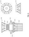
- FIG. 6illustrates various views of a multi-purpose bearing plate in accordance with implementations of various techniques described herein.
- FIG. 7illustrates various views of a multi-purpose bearing plate in a slope bracket configuration in accordance with implementations of various techniques described herein.
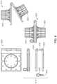
- FIG. 8illustrates various views of a post hinge attachment in accordance with implementations of various techniques described herein.
- FIG. 9illustrates various views of a swivel caster shoe in accordance with implementations of various techniques described herein.
- FIG. 10illustrates different standard post assembly applications using the multi-purpose bearing plate in accordance with implementations of various techniques described herein.
- FIG. 11illustrates drophead components and a configuration showing a drophead coupled to a modular ledger beam in accordance with implementations of various techniques described herein.
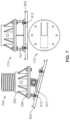
- FIG. 12illustrates various views of a heavy duty or mega-shore bearing plate in accordance with implementations of various techniques described herein.
- FIG. 13illustrates various system component drawings for modular ledger panel components in accordance with implementations of various techniques described herein.
- FIG. 14illustrates various modular ledger configuration examples in accordance with implementations of various techniques described herein.
- FIG. 16illustrates ledger rail fittings in accordance with implementations of various techniques described herein.
- FIG. 17illustrates a ledger strut and bracing assembly range in accordance with implementations of various techniques described herein.
- FIG. 18illustrates examples of modular header beams in accordance with implementations of various techniques described herein.
- FIG. 19illustrates beam and joist components in accordance with implementations of various techniques described herein.
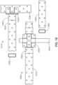
- FIG. 20illustrates modular shoring using standard panel decking in accordance with implementations of various techniques described herein.
- FIG. 21illustrates modular shoring using standard joist decking in accordance with implementations of various techniques described herein.
- FIG. 22illustrates a modular shoring plan where standard aluminum panels and filler are used to provide shoring in accordance with implementations of various techniques described herein.
- FIG. 23illustrates modular shoring sections and details in accordance with implementations of various techniques described herein.
- FIG. 24illustrates various components of the integrated construction system being used together to form a tunnel form in accordance with implementations of various techniques described herein.
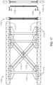
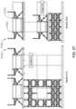
- FIG. 27illustrates an elevational view of the HD shoring application in accordance with implementations of various techniques described herein.
- ledger assemblyincludes multiple ledger rails 171 , 173 , certain implementations may include only one horizontal ledger rail, e.g., ledger rail 171 , coupled to post 185 and outer wall 145 .
- ledger rail 171may be supported by bracing element 157 .
- bracing element 157can be coupled directly to ledger rail 171 using clip 195 and coupled to a fitting of post 185 using clamp 187 .
- joists 150are coupled to the bracing assembly and are used to support a platform 155 , e.g., a wood platform.
- Platform 155may provide support for shoring in addition to providing worker access via a perimeter safety deck.
- Platform 155may support a modular header beam 163 coupled to joists 120 , which in turn support a platform 161 and barrier 165 .
- the platform 161 and barrier 165are used to form an outer edge of the concrete slab 130 .
- filler 159may be included to keep modular header beam 163 and platform 161 level.
- FIG. 30shows a joist 1920 coupled to a shoring assembly 3001 that includes a modular header beam (header extrusion 1003 ), multi-purpose bearing plate 1008 , eye-bolt connector 1040 , post end fitting 1016 , and a post 1002 having post end fittings 215 .
- Joist 1920is coupled to the shoring assembly 3001 using standard joist clip 3010 as described above.
- FIG. 30shows a joist 1920 coupled to a modular ledger panel 3002 using joist/ledger clip 3005 .
- FIG. 2includes various system component drawings for modular vertical posts 205 that include post components 210 , 215 of the shoring system.
- the modular vertical posts 205may be provided in various lengths. In one implementation, the modular vertical posts 205 have lengths of 2 feet, 3 feet, 4 feet, 6 feet and 9 feet.
- Each of the posts 205is made up of a longitudinal extruded post 210 and independent fittings, e.g., ledger fitting 215 , that are fastened to the post.
- the independent fittingsare not welded to the post.
- the independent fittingsare, instead, mechanically fastened.
- the fittingsare coupled to the post by sliding the fitting down the post, twisting the fitting into place and mechanically fastening the fitting to the post.
- the fittingis twisted into place using a groove 207 lathed into the ribs of the post 205 .
- the groove 207is obscured by the fitting 215 .
- Fittingsare placed onto the post at predetermined intervals. In one implementation, fittings fastened to the post are placed 12 inches apart.
- FIG. 29illustrates a post without fittings.
- Post 2905includes ribbed portions 2925 , 2930 , 2935 , 2940 and grooves 2910 , 2915 , 2920 .
- the postis formed as a longitudinal extrusion having ribs.
- the grooves 2910 , 2915 , 2920are lathed/cut into the ribs of the post 2905 at predefined intervals resulting in the post having the grooves 2910 , 2915 , 2920 and the ribbed portions 2925 , 2930 , 2935 , 2940 .
- the fittingsare coupled to the post by sliding them down the ribbed portions 2925 , 2930 , 2935 , 2940 of the post. The fittings are then twisted into place using grooves 2910 , 2915 , 2929 .
- Screw legs 255are provided in various lengths and are used to adjust a height of the vertical post. The height of the post may be adjusted by using the screw legs on one or both ends of the vertical post.
- the bearing plate 220 , mega-shore bearing plate 225 , slope bracket 230 , post hinge 235 , screw leg connector clips 240 , swivel caster shoe 245 , and deck drophead 250are used with the vertical posts to provide various shoring application configurations.
- FIG. 2further includes a side view of one configuration of a shoring assembly 260 using vertical posts 265 , screw legs 270 , the ledger panel assembly 275 , bearing plates 280 , a header beam 285 , and joists 290 .
- Fitting ring 307is used to attach a ledger or ledger assembly to post 305 .
- Ledgers and ledger assembliesare described in more detail below in FIGS. 13 - 17 .
- the fitting ring 307is spaced every 12 inches along the post 305 .
- the fitting ring 307is slid down the post 305 and then twisted into place on the post 305 . After twisting the fitting ring 307 into place on the post 305 , the fitting ring 307 is mechanically fastened to the post, e.g., with a screw.
- the featureis unique to this system, as all others weld connection fittings to the posts
- the post 305is configured to be a complete extruded piece, e.g., constructed of aluminum.
- the post 305is cut to a specific length.
- a groove, e.g., groove 207is lathed into the circumference of the post 305 at predetermined locations along the post 305 .
- the grooveis lathed into the post 305 every 12 inches.
- the grooveis a 1 ⁇ 2 inch cut groove.
- the fitting ring 307slides down the post 305 and twists into place at each groove.
- View 320shows the fitting ring 307 being twisted into the groove, which is shown in FIG. 29 .
- View 320shows a circular shaft portion 335 of the post 305 .
- View 310 and 315are top and side views of the fitting ring 307 , respectively. As previously described, the rings are twisted into place as shown in view 320 and mechanically fastened as shown in view 325 , e.g., using screw 330 .
- FIG. 29there are grooves 2910 , 2915 , 2920 that are cut into the post extrusion 2905 .
- Protrusion 343 of fitting ring 307fits into the groove 2910 , 2915 , 2920 .
- screws 330are used to hold the fitting ring 307 in place on the post extrusion 2905 .
- the screws 330 that hold the fitting ring 307 in placeare seated through hole 339 .
- Optional hole 341can be used for future attachments, such as lateral plan bracing or cable bracing.
- Configuring posts in the manner described aboveallows for the installation of posts and ledgers without welding.
- configuring posts in this mannerfurther allows posts to take a load.
- Prior art systemsdon't allow a ledger to put a load from a ledger onto a post.
- FIG. 4 and FIG. 5include post end components.
- the post end componentsmay include the post end fitting of FIG. 4 and/or the screw leg components of FIG. 5 .
- FIG. 4shows various views 405 , 410 , 415 , 420 of a post end fitting.
- View 405is a top cross-sectional view of a post end fitting.
- Views 410 , 415 , 420are top cross-sectional, side cross-sectional, and side view respectively, of a post end fitting coupled to a post.
- the post end fittingcan be used on a top portion and a bottom portion of each post.
- the post end fittingis configured to be a permanent fitting.
- Shoringis generally used repetitively from one concrete pour to the next. In typical prior art shoring systems, the shoring system is completely disassembled and then re-assembled on the next position.
- the present integrated construction systemprovides the ability to keep much of the setup intact and fly the assembly with a crane from one setup to the next to reduce labor costs.
- the screw leg clipsallow the screw legs to remain attached to the posts, so the screw legs will still turn for adjustment, but also provide the ability to move the post and screw leg as a unit from one pour to the next without being disassembled.
- FIG. 5shows a top view 510 of a screw leg end fitting.
- FIG. 5shows a side view 515 of the screw leg end fitting.
- the screw leg assembly 520 , 525 , 530is used to vary the height of the shoring assembly, e.g., shoring assembly 260 .
- a portion of the screw leg assembly 520 , 525 , 530fits inside of the post 545 .
- Adjustable legse.g., screw legs, are used to provide a height needed for a particular application, e.g., within an adjustment range.
- the screw leg thread 525is used with a screw leg end fitting 520 and a screw leg adjusting nut 530 .
- the screw leg adjusting nut 530can be a twisted wing nut.
- the configuration shown in FIG. 5allows for an adjustable post having non-welded components.
- FIG. 8shows various views of a post hinge attachment.
- View 805shows a bottom plate of a post hinge assembly.
- View 810shows a post hinge assembly, which includes a top plate 825 , the bottom plate 805 , a barrel 830 , and a screw fastener 835 and screw 840 .
- View 815shows the post hinge assembly with posts 845 , 850 in an open state.
- View 820shows the post hinge assembly with posts 845 , 850 in a closed state.
- the post hinge assemblyis useful in moving shoring components.
- FIG. 9shows various views 905 , 910 , 915 of a swivel caster shoe.
- Swivel caster shoescan be mounted to a post assembly 917 using the multi-purpose bearing plate 922 .
- View 905shows one implementation of a swivel caster shoe 935 coupled to a post assembly 920 and a screw leg assembly 925 using a multi-purpose bearing plate 930 .
- View 910is a top view of the swivel caster shoe.
- View 915is side view of the swivel caster shoe.
- FIG. 10shows views 1005 , 1010 , 1015 , 1020 of different standard post assembly applications using the multi-purpose bearing plate.
- the same multi-purpose bearing platecan be used for different applications.
- the prior artuses different bearing plates for different applications.
- View 1005shows a sloped slab application.
- the sloped slab applicationincludes a slope bracket 1001 .
- the slope bracket 1001is coupled to multi-purpose bearing plate 1008 using screws 1027 .
- Slope bracket 1001is also coupled to screw leg 1006 using screws 1029 .
- Screw leg 1006is further coupled to post 1002 .
- View 1010shows a screw leg and header beam application.
- screw leg 1006is coupled to post 1002 .
- Screw leg 1006is also coupled to multi-purpose bearing plate 1008 , e.g., using screws 1027 (not shown).
- Multi-purpose bearing plate 1008is coupled to header extrusion 1003 using eye-bolt connector 1040 .
- View 1015shows an application where a header beam is directly coupled to the post.
- post 1002is coupled to post end fitting 1016 .
- Post end fitting 1016is also coupled to multi-purpose bearing plate 1008 , e.g., using screws 1027 (not shown).
- Multi-purpose bearing plate 1008is coupled to header extrusion 1003 using eye-bolt connector 1040 .
- the modular postscan be used with the same multi-purpose bearing plate to provide different applications.
- FIG. 11shows drophead components 1105 and a configuration 1110 showing a drophead 1102 coupled to a modular ledger beam 1107 .
- Drophead components 1105include a drophead top plate 1112 , a drophead base plate 1114 , a drop head inner tube 1116 , a drop head header seat 1118 , and a drophead stripping nut 1120 .
- the drophead 1102provides the ability to drop the shoring and leave the posts in place for reshoring.
- the drophead componentsmount to the end of a post or screw leg.
- FIG. 12shows various views 1205 , 1210 , 1215 , 1220 of a heavy duty or mega-shore bearing plate.
- View 1205is a top view of a mega-shore bearing plate 1202 .
- the mega-shore bearing plate 1202is constructed of steel.
- the mega-shore bearing plate 1202may be coupled to a beam or a modular header beam (e.g., modular header beam 1912 ) near a top portion of a shoring assembly using a metal clip, e.g., standard joist clip 3010 .
- a top surface of mega-shore bearing plate 1202has an outer boundary defining an outer edge of the bearing plate.
- the top surface of mega-shore bearing plate 1202has a plurality of inner boundaries 1224 , 1234 , 1236 , 1238 within the multi-purpose bearing plate 1202 .
- Each inner boundary 1224 , 1234 , 1236 , 1238defines an area 1240 , 1242 , 1244 , 1246 shaped to interchangeably accommodate a plurality of components of the integrated construction system.
- a plurality of members 1226 , 1248 , 1250 , 1252are formed on an outer surface of each inner boundary 1224 , 1234 , 1236 , 1238 .
- FIG. 20shows modular shoring using standard panel decking.
- Item 2005is a side view of a shoring configuration that uses a post 2015 , deck drop head assembly 2020 , and a modular header beam 2025 to support standard aluminum form panels 2030 , and plywood filler 2035 in a shoring application.
- Deck drop head assembly 2020includes a plurality of couplings/fittings made into an adjustable assembly, shown in FIG. 11 , as an exploded view item 1105 with individual items 1112 , 1114 , 1116 , 1118 , 1120 and an assembled view item 1102 . This is the same as FIG. 20 with items 2007 , 2008 , 2009 , 2011 and 2020 .
- FIG. 21shows modular shoring using standard joist decking.
- Item 2105is a side view of a shoring configuration that uses a post 2015 , deck drop assembly 2020 , and a modular header beam 1912 to support joists 1920 , 1935 , 1940 , 1945 holding up plywood deck material 2135 .
- Deck drop head assembly 2020includes a plurality of couplings 2007 , 2009 , 2011 .
- the plurality of couplings 2007 , 2009 , 2011are shaped to accommodate the plurality of hooks 1909 of the modular header connector fitting 1903 .
- the modular header beam 1912is coupled to the deck drop head assembly 2020 via modular header connector fitting 1903 and supports the plywood deck material 2135 using joists 1920 , 1935 , 1940 , 1945 and deck drop head assembly 2020 .
- Joists 1920 , 1935 , 1940 , 1945may be coupled to the plywood deck material 2135 using synthetic nailers 1925 , 1950 , 1955 , 1960 .
- the standard panels 2030 , 2032 of FIG. 20are 4′′ deep.
- the joists 1920 , 1935 , 1940 , 1945 of FIG. 21are 6.5′′ deep.
- 0.5′′ thick plywoodsits on top of joists 1920 , 1935 , 1940 , 1945 .
- a joist and plywood configurationhas a total depth of 7′′.
- the difference between the standard panel configuration of FIG. 20 and the joist/plywood configurationis 3′′.
- the three fittings 2007 , 2009 , 2011 on the drophead attachment 2020are spaced 3′′ apart. Because of the difference in depth of the two configurations ( FIG. 20 and FIG. 21 ), header beam 1912 is coupled to the deck drop head assembly 2020 using the top two fittings 2007 , 2009 in FIG. 20 and is coupled to the deck drop head assembly 2020 using the bottom two fittings 2009 , 2011 in FIG. 21 .
- the modular header beam 1912is a hollow aluminum extrusion. As shown in FIG. 18 , FIG. 19 , FIG. 20 and FIG. 21 , the modular header beam has a first end and a second end and is configured to interchangeably support shoring panels of a shoring assembly (see FIG. 20 ) and decking panels of a decking assembly (see FIG. 21 ).
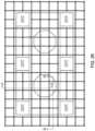
- FIG. 22shows an implementation of a modular shoring plan of an integrated construction system where standard aluminum panels and filler are used to provide shoring.
- this implementationshows 2 ⁇ 6 and 3 ⁇ 6 panels, e.g., panels 2205 , 2207 , being used to provide shoring for a horizontal concrete slab.
- different sized filler panelscan be added as needed.
- FIG. 22shows 12 inch (panel 2213 ) and 3 foot (panel 2215 ) panels. Panels in prior art shoring systems are only designed for deck slabs. Prior art shoring panels were not used for columns, walls, etc.
- the present integrated construction systemuses panels that can be used vertically for formwork and horizontally for shoring applications.
- FIG. 22shows 2 ⁇ 6 and 3 ⁇ 6 panels, e.g., panels 2205 , 2207 , being used to provide shoring for a horizontal concrete slab.
- different sized filler panelscan be added as needed.
- FIG. 22shows 12 inch (panel 2213 ) and 3 foot (panel 22
- FIG. 22also shows a perimeter safety deck 2209 .
- FIG. 22additionally shows an access bay 2211 that provides access to a lower level of a structure under construction.
- the integrated construction systemincludes components that may be used interchangeably in formwork, shoring and/or worker access configurations. Different views of the standard aluminum panels being supported by components of the integrated construction system are described below with respect to FIG. 23 . The views described below are denoted by an A-A view, which provides a view in a first direction relative to the shoring application and a B-B view, which provides a view in a second direction relative to the shoring application.
- FIG. 23shows an implementation of modular shoring sections and details.
- Section A-Ais a side view of the shoring support structure. A portion 2301 of Section A-A corresponds to the elements present in FIG. 1 .
- various posts 2305 and bracing assemblies 2310are used to support standard aluminum panels 2315 holding up a poured concrete slab 2320 .
- a perimeter safety deck 2325is formed from a bracing assembly 2340 , joists 2335 , a ledger rail 2350 and a bracing element 2345 .
- Section B-Bis a view from a different side showing the posts 2302 , bracing assemblies 2304 , standard aluminum panels 2306 , header beams 2308 , and the perimeter safety deck 2312 .
- the perimeter safety deckuses an optional pinlock guardrail 2360 .
- FIG. 23further shows, in greater detail, a view 2355 of a column area of the example shoring deck.
- This implementationillustrates how to use standard aluminum form panels for both vertical and horizontal applications.
- this implementationmay be used in a drop deck shoring application.
- FIG. 24shows various components of the integrated construction system being used together to form a tunnel form.
- the aluminum form panelsare used in a hybrid application where both a formwork and a shoring configuration are used to create the tunnel form.
- This configurationincludes formwork panels 2405 , 2410 , culvert form 2415 , modular header beam 2420 , bracing assemblies 2425 , 2530 , posts 2435 coupled to screw leg assemblies 2460 , tie assemblies 2440 , standard adjustable filler 2450 , and wood shim 2455 .
- swivel caster shoe 2445may be coupled to posts 2435 via screw leg assembly 2460 .
- Tunnel form applicationscan be used to provide an underground culvert, e.g., under a road, that water flows through.
- FIG. 24utilizes both formwork and shoring components to achieve a particular configuration.
- Using formwork and shoring components of the present systemminimizes the amount of components needed from disparate systems and also minimizes the amount of custom items that would need to be crafted to achieve a configuration similar to the configuration shown in FIG. 24 .
- FIG. 25shows two views that show a rollback shearwall deck.
- the rollback mechanismis shown in a set position, i.e., adjacent to the concrete wall 2502 .
- the rollback mechanismincludes one or more standard panels 2504 , at least one first vertical ledger rail 2506 coupled to at least one horizontal ledger rail 2512 and supported by brace 2508 .
- the one or more horizontal ledger railsare coupled to a bracing assembly 2518 by a rollback strut 2516 .
- the bracing assembly 2518is coupled to at least one second vertical ledger rail 2514 and supported by brace 2522 .
- the rollback mechanismis shown in a fly position, i.e., pulled back from the concrete wall.
- FIG. 25provides a rollback shear wall deck system and worker access platform application. Ledger panels are used to provide this rollback mechanism in both vertical and horizontal configurations.
- FIG. 25also shows landing bracket 2524 , 2526 and landing bracket 2528 .
- the arrangement shown in views 2505 , 2510is called a “Roll-Back Jump-Form” because the form jumps from one elevation to the next as vertical construction progresses.
- the present systemutilizes standard components, with a few additional items, e.g., various fillers or other items, to satisfy particular formwork and shoring applications.
- Prior art systemshave more specialized systems and do not use standard components that can be used in various configurations to address various needs.
- FIG. 25illustrates another example of using an integrated construction system to provide both formwork and shoring to form an exterior shearwall, for example, those typically found on high rise buildings.
- the wall form and platformare assembled as a unit to allow worker access outside of the building limits at elevation
- the wall form and work platformcan be picked up with a crane as a unit and landed onto a bracket at the next elevation.
- the wall form and work platformalso allow the crane rigging to be released safely by the construction workers.
- the crane riggingis released more safely because the form panel seats itself onto the bracket securely and uses gravity to hold it in-place without human interaction. This allows the workers to access the platform safely to remove the rigging and complete the next wall pour.
- FIG. 28illustrates a block diagram of a method 2800 of providing an integrated construction system.
- a first panel for a formwork configuration of an integrated construction systemis provided.
- a second panel for a shoring configuration of the integrated construction systemis provided.
- a third panel for a worker access configuration of the integrated construction systemis provided.
- the first panel, the second panel, and the third panelare a same panel type, e.g., modular ledger or standard aluminum panel (form panel).
- the postsare all aluminum.
- the fittingsmay be cast steel or cast aluminum.
- the ledger panelsare made of aluminum.
- the end fittings with the screw mechanismmay be steel.
- the vertical strutsmay be steel.
- the cross bracemay be an aluminum strap. In this manner, the bracing assembly can be a combination of aluminum and steel.
- the present shoring systemdoes not use any welded aluminum.
- the present shoring systemincludes a number of advantages and benefits.
- the present shoring systemis part of a larger integrated construction system that provides a total solution for formwork, shoring and heavy-duty access.
- This new larger integrated construction systemhas significantly less items in its usable inventory, as compared to other independent task focused systems, i.e., prior art independent formwork systems, prior art independent shoring systems, and prior art independent heavy-duty access systems.
- the present integrated construction systemhas a unique approach to the type of materials used in its construction, as well as the method of manufacture.
- the present integrated construction systemby design, minimizes the number of separate components needed to provide shoring, formwork and worker access application.
- the integrated construction systemfurther provides a unique method of manufacturing the integrated construction system components.
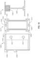
- FIG. 31illustrates standard panel assembly plan views. Top/bottom 3110 , 3120 and cutaway views 3105 , 3115 are shown for both 3 ft (panel 3110 ) and 2 ft panel (panel 3120 ) widths.
- FIG. 32illustrates elevational views 3210 , 3220 of the standard panel assembly for 2′ (panel 3120 ) and 3′ (panel 3110 ) widths.
- Top/bottom 3205 , 3215 and side elevational 3225 views of panels 3110 , 3120are also shown.
- Each standard panel 3110 , 3120includes side rails 3227 , inner rails 3231 and tie extrusions 3229 .
- Standard panelscan be 2′ or 3′ in width.
- Each standard panel of width 2′ or 3′can have a panel length of 3′, 6′, or 9′.
- first, second, etc.may be used herein to describe various elements, these elements should not be limited by these terms. These terms are only used to distinguish one element from another.
- a first object or stepcould be termed a second object or step, and, similarly, a second object or step could be termed a first object or step, without departing from the scope of the invention.
- the first object or step, and the second object or stepare both objects or steps, respectively, but they are not to be considered the same object or step.
Landscapes
- Engineering & Computer Science (AREA)
- Architecture (AREA)
- Structural Engineering (AREA)
- Civil Engineering (AREA)
- Mechanical Engineering (AREA)
- Mining & Mineral Resources (AREA)
- Electromagnetism (AREA)
- Physics & Mathematics (AREA)
- Life Sciences & Earth Sciences (AREA)
- General Life Sciences & Earth Sciences (AREA)
- Geochemistry & Mineralogy (AREA)
- Geology (AREA)
- Forms Removed On Construction Sites Or Auxiliary Members Thereof (AREA)
Abstract
Description
Claims (20)
Priority Applications (1)
| Application Number | Priority Date | Filing Date | Title |
|---|---|---|---|
| US17/861,087US12352060B2 (en) | 2016-06-24 | 2022-07-08 | Load bearing components and safety deck of an integrated construction system |
Applications Claiming Priority (8)
| Application Number | Priority Date | Filing Date | Title |
|---|---|---|---|
| US201662354325P | 2016-06-24 | 2016-06-24 | |
| US201762471173P | 2017-03-14 | 2017-03-14 | |
| US15/630,923US10472823B2 (en) | 2016-06-24 | 2017-06-22 | Formwork system |
| US15/845,962US10465399B2 (en) | 2016-06-24 | 2017-12-18 | Integrated construction system |
| US15/910,698US10415262B2 (en) | 2016-06-24 | 2018-03-02 | Modular ledgers of an integrated construction system |
| US15/971,620US11976483B2 (en) | 2016-06-24 | 2018-05-04 | Modular posts of an integrated construction system |
| US16/222,825US11306492B2 (en) | 2016-06-24 | 2018-12-17 | Load bearing components and safety deck of an integrated construction system |
| US17/861,087US12352060B2 (en) | 2016-06-24 | 2022-07-08 | Load bearing components and safety deck of an integrated construction system |
Related Parent Applications (1)
| Application Number | Title | Priority Date | Filing Date |
|---|---|---|---|
| US16/222,825DivisionUS11306492B2 (en) | 2016-06-24 | 2018-12-17 | Load bearing components and safety deck of an integrated construction system |
Publications (2)
| Publication Number | Publication Date |
|---|---|
| US20220341192A1 US20220341192A1 (en) | 2022-10-27 |
| US12352060B2true US12352060B2 (en) | 2025-07-08 |
Family
ID=66243512
Family Applications (4)
| Application Number | Title | Priority Date | Filing Date |
|---|---|---|---|
| US16/222,825ActiveUS11306492B2 (en) | 2016-06-24 | 2018-12-17 | Load bearing components and safety deck of an integrated construction system |
| US17/723,158ActiveUS12291885B2 (en) | 2016-06-24 | 2022-04-18 | Fitting ring |
| US17/861,087ActiveUS12352060B2 (en) | 2016-06-24 | 2022-07-08 | Load bearing components and safety deck of an integrated construction system |
| US17/988,960ActiveUS11970873B2 (en) | 2016-06-24 | 2022-11-17 | Bearing plate of an integrated construction system |
Family Applications Before (2)
| Application Number | Title | Priority Date | Filing Date |
|---|---|---|---|
| US16/222,825ActiveUS11306492B2 (en) | 2016-06-24 | 2018-12-17 | Load bearing components and safety deck of an integrated construction system |
| US17/723,158ActiveUS12291885B2 (en) | 2016-06-24 | 2022-04-18 | Fitting ring |
Family Applications After (1)
| Application Number | Title | Priority Date | Filing Date |
|---|---|---|---|
| US17/988,960ActiveUS11970873B2 (en) | 2016-06-24 | 2022-11-17 | Bearing plate of an integrated construction system |
Country Status (1)
| Country | Link |
|---|---|
| US (4) | US11306492B2 (en) |
Families Citing this family (16)
| Publication number | Priority date | Publication date | Assignee | Title |
|---|---|---|---|---|
| US11624196B2 (en) | 2016-06-24 | 2023-04-11 | Apache Industrial Services, Inc | Connector end fitting for an integrated construction system |
| US11976483B2 (en) | 2016-06-24 | 2024-05-07 | Apache Industrial Services, Inc | Modular posts of an integrated construction system |
| US12195961B2 (en) | 2016-06-24 | 2025-01-14 | Apache Industrial Services, Inc. | Formwork system |
| US11306492B2 (en) | 2016-06-24 | 2022-04-19 | Apache Industrial Services, Inc | Load bearing components and safety deck of an integrated construction system |
| US10472823B2 (en) | 2016-06-24 | 2019-11-12 | Apache Industrial Services, Inc. | Formwork system |
| US11047142B1 (en) | 2020-07-31 | 2021-06-29 | Bond Formwork Systems, LLC | Main beam structure and profile for formwork grid systems |
| US11268289B2 (en) | 2020-07-31 | 2022-03-08 | Bond Formwork Systems, LLC | Drophead nut for formwork grid systems |
| US10982452B1 (en)* | 2020-07-31 | 2021-04-20 | Bond Formwork Systems, LLC | Secondary joist profile for grid systems |
| US11763109B2 (en)* | 2021-01-27 | 2023-09-19 | Paratech, Incorporated | Electronic strut monitor |
| GB2605968B (en)* | 2021-04-19 | 2025-04-02 | J Mac Safety Systems Ltd | A corner mounting bracket for a work platform |
| US12049980B1 (en)* | 2021-08-06 | 2024-07-30 | Art Guild of Philadelphia, Inc. | System for securing an elongated member |
| CN114352007A (en)* | 2022-01-18 | 2022-04-15 | 无锡信泰模架科技有限公司 | Construction method of unit type supporting and early-dismantling formwork system |
| CN114352006A (en)* | 2022-01-18 | 2022-04-15 | 无锡信泰模架科技有限公司 | Modular recyclable construction process for concrete slab pouring construction |
| CA3178396A1 (en)* | 2022-02-14 | 2023-08-14 | Kyle Marsh | Temporary building enclosure |
| CN115726564B (en)* | 2022-10-25 | 2024-10-01 | 中建海峡建设发展有限公司 | Method for installing and detaching overweight high formwork support system |
| CN116804338A (en)* | 2023-06-14 | 2023-09-26 | 中建铁投轨道交通建设有限公司 | A support truss for the inner formwork of the variable cross-section side wall and its construction method |
Citations (450)
| Publication number | Priority date | Publication date | Assignee | Title |
|---|---|---|---|---|
| US559931A (en) | 1896-05-12 | Mold for cisterns | ||
| US1163188A (en) | 1914-07-17 | 1915-12-07 | Guy B Waite | Adjustable centering for reinforced-concrete floor construction. |
| US1176005A (en) | 1914-07-17 | 1916-03-21 | Guy B Waite | Adjustable centering for concrete floor constructions. |
| US1473504A (en) | 1922-12-23 | 1923-11-06 | Neely Richard Earl | Rail clamp |
| US1575268A (en) | 1925-11-04 | 1926-03-02 | Frank H Howard | I-beam clamp |
| US1653126A (en) | 1923-07-30 | 1927-12-20 | Duff Mfg Co | Mine post or jack |
| USRE17629E (en) | 1930-03-25 | I-beam clamp | ||
| US1768543A (en) | 1926-05-15 | 1930-07-01 | Clausing George Walter | Hanger |
| US1890386A (en) | 1928-12-13 | 1932-12-06 | Builders Patent Scaffolding Co | Ledger clamp |
| US1890336A (en) | 1931-06-02 | 1932-12-06 | Frank E Nodine | Locking means |
| US1919405A (en) | 1928-04-16 | 1933-07-25 | William H Wilson | Truss |
| US1970547A (en) | 1933-02-11 | 1934-08-21 | Macgregor S Anderson | Wall form |
| US1974628A (en) | 1932-04-16 | 1934-09-25 | Cleveland Crane Eng | Clamp |
| US1974752A (en) | 1933-08-17 | 1934-09-25 | Roberg Otto | Concrete mold construction |
| US2181163A (en) | 1939-08-11 | 1939-11-28 | Roy W Akins | Adjustable support for buildings or the like |
| US2261907A (en) | 1939-06-23 | 1941-11-04 | Safway Steel Scaffolds Co Of W | Scaffold bracket |
| US2357819A (en) | 1940-06-07 | 1944-09-12 | Greer Robert Royden | Supporting frame for screens |
| US2382201A (en) | 1943-05-01 | 1945-08-14 | Joseph R Burke | Timber load carrying member |
| FR926917A (en) | 1946-05-14 | 1947-10-15 | Scaffolding console | |
| US2479962A (en) | 1946-10-17 | 1949-08-23 | Alf M Paulson | Scaffold construction |
| US2511584A (en) | 1947-05-12 | 1950-06-13 | Hayden C Hill | Wall form construction |
| US2573806A (en) | 1948-12-23 | 1951-11-06 | Adeline E E Paterson | Unidirectional restraining device for a fastening cord |
| US2631346A (en) | 1949-12-29 | 1953-03-17 | Fargo Mfg Co Inc | Messenger wire clamp |
| US2760249A (en) | 1953-06-08 | 1956-08-28 | Wilson Thomas Woodrow | Concrete wall form |
| US2804673A (en) | 1954-06-08 | 1957-09-03 | Fortunat B Fex | Concrete beam form supports |
| US2832559A (en) | 1953-06-08 | 1958-04-29 | Superior Concrete Accessories | Adjustable brace |
| FR1165329A (en) | 1957-01-26 | 1958-10-21 | Railing fixing device, in particular for buildings under construction and scaffolding erected using this device | |
| US2877974A (en) | 1954-01-06 | 1959-03-17 | Thomas C Estes | Adjustable beam clamp |
| GB838828A (en) | 1956-12-28 | 1960-06-22 | Donald Mayer King | Improvements in or relating to devices for facilitating the attachment of items of equipment or other structural members to joists, beams or the like |
| US2944120A (en) | 1958-06-12 | 1960-07-05 | Zorro D Ruben | Safety foot switch |
| US2945662A (en) | 1955-03-07 | 1960-07-19 | Economy Forms Corp | Adjustable brace connector unit |
| US2970677A (en) | 1955-12-09 | 1961-02-07 | Gen Fireproofing Co | Metallic partitioning devices |
| US2974762A (en) | 1952-09-23 | 1961-03-14 | Hunnebeck Emil Mauritz | Girder units |
| US2976597A (en) | 1958-11-03 | 1961-03-28 | Symons Clamp & Mfg Co | Concrete wall form extension |
| GB877463A (en) | 1958-08-08 | 1961-09-13 | John Burton | A new or improved construction of scaffold frame |
| US3005282A (en) | 1958-01-28 | 1961-10-24 | Interlego Ag | Toy building brick |
| US3018898A (en) | 1960-03-14 | 1962-01-30 | John G Molek | Portable bracket pole |
| US3054486A (en) | 1961-06-29 | 1962-09-18 | Hico Corp Of America | Form supporting girder for use in concrete construction |
| US3077653A (en) | 1960-09-07 | 1963-02-19 | Edward B Ward | Concrete wall form |
| US3124330A (en) | 1964-03-10 | I-beam clamp | ||
| US3131902A (en) | 1962-09-06 | 1964-05-05 | Jr George Zak | Shoring device for boats |
| US3168772A (en) | 1963-10-10 | 1965-02-09 | Utah Construction & Mining Co | Form system for concrete construction |
| US3171627A (en) | 1962-04-19 | 1965-03-02 | Union Metal Products Inc | Extensible shoring device |
| US3204918A (en) | 1962-04-23 | 1965-09-07 | Symons Mfg Co | Concrete wall form panel units and connecting means therefor |
| US3217833A (en) | 1964-06-29 | 1965-11-16 | Delmer W Smith | Safety device |
| US3222829A (en) | 1962-06-18 | 1965-12-14 | Lucy M Bening | Knockdown shelter |
| US3247639A (en) | 1963-11-13 | 1966-04-26 | Rambelle Robert Dela | Form supporting girder for use in concrete construction |
| US3288427A (en) | 1963-07-10 | 1966-11-29 | Pluckebaum Paul | Assemblable formwork for reinforced concrete structures |
| US3318057A (en) | 1964-03-24 | 1967-05-09 | Robertson Co H H | Pedestal floor construction |
| US3325957A (en) | 1963-06-10 | 1967-06-20 | Standard Iron & Wire Works Inc | Adjustable length joist |
| US3392801A (en) | 1964-03-19 | 1968-07-16 | Kenneth W. Gethmann | Scaffold device |
| US3420012A (en) | 1966-09-01 | 1969-01-07 | Ernest C Liskey Jr | Elevated floor system |
| US3462110A (en) | 1967-06-26 | 1969-08-19 | Bliss Co | Support assembly |
| US3465995A (en) | 1968-02-23 | 1969-09-09 | Viber Co | I-beam clamp |
| US3472539A (en) | 1969-01-02 | 1969-10-14 | Streater Ind Inc | Tubular frame joint member |
| US3486287A (en) | 1967-09-23 | 1969-12-30 | Massey Ferguson Ind Ltd | Wall assembling device |
| US3491852A (en) | 1968-06-20 | 1970-01-27 | Paul W Leist | Ladder scaffold |
| US3493208A (en) | 1967-05-06 | 1970-02-03 | Masataro Sato | Bracket for scaffolding |
| DE2006912A1 (en) | 1969-02-24 | 1970-09-03 | Graphic Sciences Inc., Danbury, Conn. (V.St.A.) | Image transmission device |
| US3533587A (en) | 1968-10-04 | 1970-10-13 | Alcan Aluminum Corp | Beam clamp |
| US3533857A (en) | 1967-11-29 | 1970-10-13 | Hughes Aircraft Co | Method of restoring crystals damaged by irradiation |
| US3550723A (en) | 1968-11-29 | 1970-12-29 | Tom D Gentry | Bridge scaffold |
| US3559357A (en) | 1969-07-09 | 1971-02-02 | David A Lowe | Modular building system |
| CH506685A (en) | 1970-04-29 | 1971-04-30 | Baechli Jules | Scaffold girders |
| US3578060A (en) | 1969-04-18 | 1971-05-11 | Lloyd Spencer | Vertically movable self-locking shutter |
| US3601356A (en) | 1969-09-09 | 1971-08-24 | Kwik Lock Form Co | Vertical stiffening arrangement for wall forms |
| US3684058A (en) | 1971-05-13 | 1972-08-15 | Ultra Products Inc | Scaffold |
| US3696578A (en) | 1970-03-06 | 1972-10-10 | Liskey Aluminum | Floor panel for an elevated floor assembly |
| US3735953A (en) | 1970-04-22 | 1973-05-29 | Mesa Ind Los Angeles | Concrete beam forms |
| US3751790A (en) | 1970-10-05 | 1973-08-14 | S Frazier | Construction of a form for concrete molding |
| US3776498A (en) | 1970-08-28 | 1973-12-04 | A Peters | Stabilizable scaffolding support bracket |
| US3790117A (en) | 1972-05-08 | 1974-02-05 | C Winkler | Auxiliary rear view mirror |
| US3815858A (en) | 1973-01-12 | 1974-06-11 | Waco Scaffold & Shoring Co | Roll out formwork support |
| US3817006A (en) | 1972-10-27 | 1974-06-18 | Bracing Syst Inc | Apparatus for supporting masonry walls against wind damage during construction |
| US3822850A (en) | 1973-01-29 | 1974-07-09 | Dell Holdings Ltd | Support for construction fence |
| US3862737A (en) | 1973-10-01 | 1975-01-28 | Hoover Ball & Bearing Co | Concrete form panels and locking means therefor |
| US3876046A (en) | 1973-07-09 | 1975-04-08 | Licentia Gmbh | Mounting of an exchangeable adaptor rail on a contact rail |
| US3885648A (en) | 1973-01-31 | 1975-05-27 | Mills Echafaudages | Bayonet - type connection |
| US3890750A (en) | 1972-12-08 | 1975-06-24 | Composite Const Systems | Construction system |
| US3900179A (en) | 1973-01-12 | 1975-08-19 | Waco Scaffold & Shoring Co | Column roll out support |
| US3900182A (en) | 1972-12-08 | 1975-08-19 | Composite Const Systems | Construction form support member |
| US3993282A (en) | 1972-12-08 | 1976-11-23 | Composite Construction Systems, Inc. | Construction form support member |
| US4003543A (en) | 1975-07-14 | 1977-01-18 | Harsco Corporation | Column lift bracket |
| GB1465950A (en) | 1973-05-10 | 1977-03-02 | Dreiskaemper Gmbh | Quick-assembly formwork |
| US4030266A (en) | 1976-02-17 | 1977-06-21 | Symons Corporation | Invertable, multi-purpose structural clamp |
| US4030694A (en) | 1976-07-14 | 1977-06-21 | Symons Corporation | Composite concrete wall form unit with a special transition bolt |
| US4032100A (en) | 1976-03-11 | 1977-06-28 | Kahn William J | Instant scaffold and paint can holder |
| US4033081A (en) | 1975-05-16 | 1977-07-05 | Perkins Jr Fred M | Modular building system |
| US4036466A (en) | 1973-12-20 | 1977-07-19 | Symons Corporation | Flying deck-type concrete form installation |
| US4070833A (en) | 1976-04-19 | 1978-01-31 | Loren Hancock | Bracing apparatus |
| US4102096A (en) | 1977-03-02 | 1978-07-25 | Symons Corporation | Leg brace assembly for adjustable shoring apparatus |
| US4106256A (en) | 1976-12-01 | 1978-08-15 | Symons Corporation | Adjustable shoring apparatus |
| US4121804A (en) | 1977-07-15 | 1978-10-24 | Leary Thomas J O | Adjustable concrete form |
| US4123031A (en) | 1976-09-14 | 1978-10-31 | Hyre Robert W | Improvements in concrete roadway-slab forming and form-elevation adjusting means |
| US4133433A (en) | 1977-03-28 | 1979-01-09 | Wolf Morris A | Merchandising display system |
| US4158452A (en) | 1977-07-13 | 1979-06-19 | Gates & Sons, Inc. | Clamping lock for looped ties |
| US4162682A (en) | 1978-01-25 | 1979-07-31 | Miller Sharon | Pivotal sectionalized wall for hog raising enclosure |
| US4163537A (en) | 1976-07-12 | 1979-08-07 | Societe Anonyme Des Ateliers Marcadet Mobilier | Bearer structure for assembling modular elements |
| US4188017A (en) | 1978-10-10 | 1980-02-12 | Gerhard Dingler | Tensioning device for frame pieces |
| US4194338A (en) | 1977-09-20 | 1980-03-25 | Trafton Ronald H | Construction components, assemblies thereof, and methods of making and using same |
| US4202145A (en) | 1978-11-20 | 1980-05-13 | Leav-Er-Rite Mfg. Co. Incorporated | Cast-in-place concrete slab pouring form |
| US4248024A (en) | 1978-03-02 | 1981-02-03 | Dahlstroem C I S | Centering for casting concrete roofs |
| US4261144A (en)* | 1979-07-05 | 1981-04-14 | Rhw, Inc. | Vertical corner post for screened-in room structure |
| US4342440A (en) | 1980-03-25 | 1982-08-03 | Eyden Everett A | Concrete deck forming apparatus |
| US4348002A (en) | 1980-03-25 | 1982-09-07 | Eyden Everett A | Hanger for concrete deck forming apparatus |
| US4349491A (en) | 1980-03-25 | 1982-09-14 | Eyden Everett A | Method for forming a concrete deck |
| EP0062420A1 (en) | 1981-03-27 | 1982-10-13 | Aluma Systems Incorporated | Concrete forming structures |
| US4371203A (en) | 1981-07-13 | 1983-02-01 | Munro Donald C | Universal beam clamp |
| US4372425A (en) | 1981-01-12 | 1983-02-08 | Michael Murphy | Auxiliary scaffolding attachment |
| FR2527254A1 (en) | 1982-05-19 | 1983-11-25 | Ricard Jacques | Device for assembling shuttering panels - comprises pivoting linkages on adjacent panels which are interconnected by traction device |
| US4458461A (en) | 1981-07-27 | 1984-07-10 | Planscape Systems (N.Z.) Limited | Support posts and/or a partitioning system |
| GB2133826A (en) | 1983-01-11 | 1984-08-01 | Acrow | Adjusting curvature of formwork |
| US4470574A (en) | 1978-12-11 | 1984-09-11 | Jackson George W | Support structure for building forms |
| US4473209A (en) | 1982-01-15 | 1984-09-25 | Harsco Corporation | Prefabricated wall form modular unit |
| US4481748A (en)* | 1980-09-10 | 1984-11-13 | Harsco Corporation | Shoring system and parts thereof |
| US4493172A (en) | 1982-08-06 | 1985-01-15 | Jones Brian D | Connector system |
| US4499967A (en)* | 1983-11-09 | 1985-02-19 | Anderson Carl E | Scaffolding staging |
| GB2145761A (en) | 1983-08-04 | 1985-04-03 | Midlands Environmental Service | Roof structure and bracket for use in supporting said structure |
| US4516372A (en) | 1981-08-14 | 1985-05-14 | Grutsch George A | Concrete formwork |
| US4529163A (en) | 1984-04-20 | 1985-07-16 | Gerhard Dingler | Combination of form panels and form lock devices |
| US4558544A (en) | 1983-03-30 | 1985-12-17 | H. H. Robertson Company | Adjustable pedestal for elevated floors |
| US4582001A (en) | 1984-02-27 | 1986-04-15 | Nashville Wire Products | Shelf connector assembly |
| US4587786A (en) | 1983-10-26 | 1986-05-13 | Anthes Equipment Limited | Scaffolding and locking discs therefor |
| US4619433A (en) | 1983-09-17 | 1986-10-28 | Josef Maier | Apparatus for erecting arcuate walls of concrete or the like |
| FR2593843A1 (en) | 1986-01-24 | 1987-08-07 | Ricard Bruno | CONNECTING FLANGE FOR ASSEMBLING BEAMS, AND WOOD FRAMEWORK PRODUCED USING THE CONNECTING FLANGE |
| US4685264A (en) | 1986-04-09 | 1987-08-11 | Epic Metals Corporation | Concrete slab-beam form system for composite metal deck concrete construction |
| US4743202A (en) | 1984-08-03 | 1988-05-10 | Interlego A.G. | Current-carrying building element |
| US4742985A (en) | 1984-11-16 | 1988-05-10 | Rund-Stahl-Bau Gesellschaft M.B.H. | Formwork assembly for a poured concrete structure |
| US4761847A (en) | 1987-06-26 | 1988-08-09 | Savage Carl P | Folding ramp |
| US4776557A (en) | 1985-05-22 | 1988-10-11 | Rapid Metal Developments Ltd. | Formwork panel |
| US4787183A (en) | 1984-12-27 | 1988-11-29 | Aluma Systems Ltd. | Truss arrangement |
| US4805735A (en)* | 1988-02-28 | 1989-02-21 | Carl Anderson | Scaffolding net system |
| US4805365A (en) | 1987-12-10 | 1989-02-21 | Hamilton Industries, Inc. | Corner post assembly |
| US4813196A (en) | 1986-05-22 | 1989-03-21 | Greyhound Exhibitgroup Inc. | Structural system |
| US4821844A (en) | 1988-04-11 | 1989-04-18 | Huffman Cary A | Outrigger for scaffolding |
| US4826113A (en) | 1984-11-23 | 1989-05-02 | The Dow Chemical Company | Pipe support assembly |
| US4831791A (en) | 1984-11-20 | 1989-05-23 | Hauserman, Inc. | Space divider system |
| GB2215374A (en) | 1988-02-24 | 1989-09-20 | Kwikform Ltd Gkn | Scaffolding |
| US4880195A (en) | 1988-12-09 | 1989-11-14 | Kalamazoo Banner Works, Inc. | Banner support |
| US4881716A (en) | 1987-10-10 | 1989-11-21 | Gerhard Dingler | Assembly for prefabricated formwork |
| US4919268A (en) | 1985-06-08 | 1990-04-24 | Creative Design And Packaging Cardiff Limited | Containers |
| EP0369108A2 (en) | 1988-11-12 | 1990-05-23 | Josef Maier | Filling-in piece for shutterings |
| EP0375969A1 (en) | 1988-12-28 | 1990-07-04 | THYSSEN HÜNNEBECK GmbH | Aligning clamp for shuttering systems |
| EP0408209A2 (en) | 1989-07-08 | 1991-01-16 | Gkn Kwikform Limited | Formwork system |
| US5009050A (en) | 1990-05-15 | 1991-04-23 | Ed. Shook, Jr. | Roofing clamp |
| WO1991009191A1 (en) | 1989-12-14 | 1991-06-27 | Industrial Innovations Limited | Structure support means |
| US5029670A (en) | 1990-06-22 | 1991-07-09 | Whitmer Gerald T | Frame erection safety system and components thereof |
| US5029803A (en) | 1990-01-05 | 1991-07-09 | Peri Gmbh | Device for adapting a formwork element to given radii of a circular formwork |
| US5044601A (en) | 1989-05-30 | 1991-09-03 | Symons Corporation | Outside bay adapter for a concrete forming system |
| US5048781A (en) | 1990-04-26 | 1991-09-17 | Edward Breen | Concrete mold assembly device |
| US5078360A (en) | 1989-12-22 | 1992-01-07 | Speral Aluminium Inc. | Prefabricated assembly for poured concrete forming structures |
| US5104079A (en) | 1989-10-24 | 1992-04-14 | Lisega Gmbh | Supporting clamp for mounting constructional components, for example tubes or the like |
| US5125617A (en) | 1990-03-29 | 1992-06-30 | Miller Alan P | Adjustable radius walers for forming |
| US5127342A (en) | 1990-11-14 | 1992-07-07 | International Storage Systems | Adjustable shelving |
| US5146816A (en) | 1988-11-12 | 1992-09-15 | Josef Maier | Connecting formwork panels |
| US5150557A (en) | 1990-12-17 | 1992-09-29 | Gregory Robert K | Adjustable shoring system |
| US5154837A (en) | 1990-12-03 | 1992-10-13 | Jones A Alan | Flexible form |
| KR920008222Y1 (en) | 1990-06-14 | 1992-11-14 | 주식회사 대종건영 | Scaffolding fixture |
| US5174909A (en) | 1990-01-18 | 1992-12-29 | Western Forms, Inc. | Latching bolt mechanism and mount for concrete forming system |
| US5192145A (en) | 1990-05-21 | 1993-03-09 | Wolfgang Rixen | Cross coupling for bars |
| US5219473A (en) | 1990-03-27 | 1993-06-15 | Sandwith Stanley R | Adjustable concrete formwork system |
| US5228258A (en) | 1989-11-27 | 1993-07-20 | Fuji Jukogyo Kabushiki Kaisha | Collapsible truss structure |
| DE9305194U1 (en) | 1993-04-06 | 1993-08-26 | Plettac AG, 58840 Plettenberg | System framework |
| US5240089A (en) | 1991-07-17 | 1993-08-31 | Speral Aluminum Inc. | Modular scaffolding assembly |
| DE9309950U1 (en) | 1993-07-05 | 1993-09-16 | Paschal-Werk G. Maier GmbH, 77790 Steinach | Formwork panel with edge profiles |
| US5263296A (en) | 1991-07-17 | 1993-11-23 | Speral Aluminium Inc. | Modular scaffolding assembly |
| US5265836A (en) | 1992-07-01 | 1993-11-30 | Dale, Cox & Simon | Concrete form |
| US5292098A (en) | 1988-06-07 | 1994-03-08 | Thos. Storey (Engineers) Limited | Support work props |
| US5307601A (en) | 1992-02-06 | 1994-05-03 | Mccracken Robert G | Beam member for use in concrete forming apparatus |
| BE1006369A6 (en) | 1991-12-11 | 1994-08-02 | Callens Henri Evarist | Vibrating panel cover and covering grip for this |
| DE4328105C1 (en) | 1993-08-20 | 1994-09-29 | Paul Stange | Retaining jaw for a pipe-securing means |
| US5367852A (en) | 1991-12-27 | 1994-11-29 | Ono Tatsuo | Support system |
| US5379566A (en) | 1992-01-25 | 1995-01-10 | Peri Gmbh | Adjustable-height post |
| US5385323A (en) | 1993-10-14 | 1995-01-31 | Garelick; Richard J. | Telescoped tubular support members |
| US5447249A (en) | 1992-09-04 | 1995-09-05 | Vickers; Robert V. | Interengaging containers |
| JPH07279411A (en) | 1994-04-06 | 1995-10-27 | Kobe Steel Ltd | Form for concrete |
| US5509635A (en) | 1993-07-05 | 1996-04-23 | Paschal-Werk G. Maier Gmbh | Formwork with form panels and connecting means |
| US5529144A (en) | 1994-08-11 | 1996-06-25 | Henderson; Matt G. | Steel worker's safety clamp |
| US5549176A (en) | 1994-09-09 | 1996-08-27 | Modern Bridge Forming Co., Inc. | Bridge construction machinery and method for constructing bridges |
| EP0729536A1 (en) | 1993-11-20 | 1996-09-04 | Maier G Paschal Werk | CONTROL PANEL WITH EDGE BRIDGES FROM A FLAT-EXTRUSION PROFILE |
| US5560730A (en) | 1993-12-17 | 1996-10-01 | Scaffold Connection Corporation | Scaffold system |
| US5570500A (en) | 1994-01-22 | 1996-11-05 | Paschal-Werk G. Maier Gmbh | Clamp for connecting form panels with clamping jaws urging sections of panels together at their edges |
| US5575938A (en) | 1992-10-28 | 1996-11-19 | Tatsuo Ono | Form panel |
| US5641036A (en) | 1994-10-24 | 1997-06-24 | Maxwell; James Clifford | Climbing tree stand with backpack, climbing aid and seat |
| US5655336A (en) | 1994-09-16 | 1997-08-12 | Azar; Tony | Telescopic light metal form board |
| US5680732A (en) | 1993-12-31 | 1997-10-28 | Skouras; Joseph Alexander | Lifting and shoring jack assembly |
| US5685121A (en) | 1996-02-16 | 1997-11-11 | Defrancesco; Frank | Metal stud |
| US5711397A (en) | 1995-02-03 | 1998-01-27 | Flora; Charles D. | Safety device for steelworkers |
| JPH1046806A (en) | 1996-08-07 | 1998-02-17 | Nikken Metal:Kk | Formwork panel for concrete |
| WO1998007935A1 (en) | 1996-08-22 | 1998-02-26 | Arnfinn Saervoll | Formwork system |
| US5729948A (en) | 1996-08-29 | 1998-03-24 | Levy; Tzadok | Apparatus and method for rigidly joining construction elements to one another |
| US5729950A (en) | 1996-04-03 | 1998-03-24 | Hardy Industries, Inc. | All-metal reinforcing building frame |
| US5735100A (en) | 1996-10-07 | 1998-04-07 | 527233 B.C. Ltd. | Folding telescopic prefabricated framing units for non-load-bearing walls |
| US5746535A (en) | 1995-06-08 | 1998-05-05 | Heron Sondermaschinen Und Steuerungen Ges.M.B.H | Plate fastener |
| CN1188175A (en) | 1997-01-15 | 1998-07-22 | 安托尼奥·那瓦罗·皮利兹 | curved wall forming device |
| EP0678637B1 (en) | 1994-04-21 | 1998-07-29 | DOKA Industrie GmbH | Method and arrangement for shuttering floors |
| US5791096A (en) | 1997-03-07 | 1998-08-11 | Chen; Kingbow | Raised floor supporting structure |
| US5863020A (en) | 1995-11-01 | 1999-01-26 | Rose Manufacturing Company | Lifeline mounting apparatus |
| KR0134600Y1 (en) | 1995-09-20 | 1999-02-18 | 한준수 | Multipurpose Bracket for Construction |
| US5941486A (en) | 1997-03-24 | 1999-08-24 | Redev Management Corporation | Bracket assembly |
| US5943830A (en) | 1997-05-30 | 1999-08-31 | Dayton Superior Corporation | Knee brace bracket for tilt-up construction |
| DE19807860A1 (en) | 1998-02-25 | 1999-09-09 | Hofmann | Method for joining metal profile strip |
| US5961240A (en) | 1997-04-02 | 1999-10-05 | Aluma Enterprises Inc. | Scaffolding connector |
| DE29912555U1 (en) | 1999-07-17 | 1999-10-07 | Wilhelm Layher Vermögensverwaltungs-GmbH, 74363 Güglingen | Console device for a scaffolding device |
| US5979138A (en) | 1997-12-12 | 1999-11-09 | Allen; Timothy R. | Adjustable concrete forms |
| US5979119A (en) | 1996-03-27 | 1999-11-09 | Trafton; Ronald H. | Components and assemblies for building construction and methods of making and using same |
| US6003631A (en) | 1998-09-29 | 1999-12-21 | Knauth; Peter R. | Wall supported scaffolding device |
| US6059258A (en) | 1997-10-10 | 2000-05-09 | Jackson; George W. | Modular shoring frame and system |
| US6092623A (en) | 1999-06-25 | 2000-07-25 | Collavino; Loris | Safety anchor system |
| US6106186A (en) | 1992-07-31 | 2000-08-22 | Wenger Corporation | Modular portable stage system |
| US6161359A (en) | 1997-12-26 | 2000-12-19 | Tatsuo Ono | Shoring |
| US6173809B1 (en) | 1998-03-25 | 2001-01-16 | Mc Enterprises International, Inc. | Safety stanchions |
| US6186856B1 (en) | 1997-10-21 | 2001-02-13 | Ching Yean Chen | Toy of equilateral triangular building blocks |
| US6205739B1 (en) | 1998-10-09 | 2001-03-27 | Tomcat Global Corporation | Connector node |
| US6298629B1 (en) | 1999-08-04 | 2001-10-09 | Protecta International S.A. | Safety line anchorage assemblies |
| US6318572B1 (en) | 2000-07-20 | 2001-11-20 | Yung Lin Lai | Multifunctional knockdown rack structure |
| US6321501B1 (en) | 1999-04-19 | 2001-11-27 | James P. Ignash | Collapsible three sided truss |
| WO2002003116A1 (en) | 2000-06-30 | 2002-01-10 | Motorola, Inc. | Fiber-optic network having hybrid integrated circuit nodes |
| US20020003061A1 (en) | 2000-07-06 | 2002-01-10 | Philippe Michel J. | Scaffolding |
| US20020036118A1 (en) | 1997-12-26 | 2002-03-28 | Nisso Sangyo, Co. Ltd. | Frames and structures assembled by same |
| US6363685B1 (en)* | 2000-05-19 | 2002-04-02 | William E. Kugler | Method and apparatus for selectively adjusting the elevation of an undulating or plannar surface |
| US6370741B1 (en) | 2000-12-15 | 2002-04-16 | Haur-Wen Lu | Stationery clamp |
| US20020044823A1 (en) | 2001-11-09 | 2002-04-18 | Sosa Saul Siney | Frame connection mechanism |
| US20020084141A1 (en) | 1999-04-22 | 2002-07-04 | Thomas Donald Harrison | Scaffolding units and platforms for use with scaffolding units |
| US20020092961A1 (en) | 2001-01-12 | 2002-07-18 | Gallis Anthony J. | Modular form tube and clamp system |
| US6422345B1 (en) | 1996-08-16 | 2002-07-23 | Peri Gmbh | Dismountable facade scaffold |
| US6439344B1 (en) | 2001-01-26 | 2002-08-27 | Mc Enterprises International, Inc. | Concrete mounted safety stanchion and apparatus and methods for mounting to concrete |
| JP2002256700A (en) | 2000-12-27 | 2002-09-11 | Hideki Nakane | Concrete form, crosspiece for concrete form, and concrete placing method |
| DE10121957A1 (en) | 2001-05-05 | 2002-11-07 | Agemo Geruestbau Gmbh | Safety net temporary support frame for use during erection and dismantling of building scaffolding |
| US20020185335A1 (en) | 2001-06-11 | 2002-12-12 | Mark Verdyk | Safety device |
| US6520705B2 (en) | 2001-05-10 | 2003-02-18 | Wilson Frank Stasney, Jr. | Clamping assembly |
| US6520471B2 (en) | 2001-03-01 | 2003-02-18 | Appian Construction, Inc. | Pedestal support for an elevated paver deck assembly |
| US6554235B1 (en) | 1999-10-29 | 2003-04-29 | Force Et Forme | Support post with adjustable accessory supports |
| US6575652B2 (en) | 2001-01-16 | 2003-06-10 | Kurt F. Krauss | Structural couplings and system |
| US6591574B2 (en) | 2001-08-09 | 2003-07-15 | Troy L. Humphrey | Bracket assembly for installation of concrete forms for building foundations |
| US20030209648A1 (en) | 2002-03-22 | 2003-11-13 | Artur Schworer | Device for mounting and dismantling formwork |
| US20030213152A1 (en) | 2002-05-20 | 2003-11-20 | Kim Yong Soo | Traffic sign device |
| KR20030095163A (en) | 2002-06-29 | 2003-12-18 | 박경수 | Bracket for scaffole of construction works |
| US6688430B1 (en) | 1999-11-01 | 2004-02-10 | Pluseight Technology Ab | Device for coupling scaffolding elements |
| US20040035064A1 (en)* | 2000-05-19 | 2004-02-26 | Kugler William E. | Non-threaded apparatus for selectively adjusting the elevation of a building surface |
| US20040055249A1 (en) | 2000-10-03 | 2004-03-25 | Kennedy Stephen John | Bridge deck panels, fabrication methods and use |
| US6712543B1 (en) | 1999-07-21 | 2004-03-30 | Fms Forder-Und Montage-Systeme Schmalzhofer Gmbh | Connecting device for profiled bars with grooves |
| US6722468B2 (en) | 2002-02-01 | 2004-04-20 | James R. Albano | Suspended scaffolding system |
| JP2004156416A (en) | 2002-11-05 | 2004-06-03 | Yoshitaka Kawasaki | House foundation structure and construction method |
| US6746183B1 (en) | 2002-09-23 | 2004-06-08 | James G. Sullivan | Shoring device with outer ratcheting collar |
| US6752570B2 (en) | 2002-04-08 | 2004-06-22 | Richard Lanka | Shoring system apparatus and method for shoring |
| US6751914B2 (en) | 2002-03-01 | 2004-06-22 | Steelcase Development Corporation | Post and beam furniture system |
| US20040118065A1 (en) | 2002-09-13 | 2004-06-24 | Jackson Barry W. | Column hung shoring bracket and slab support truss system |
| GB2398848A (en) | 2003-02-26 | 2004-09-01 | Sgb Services Ltd | A wedge arrangement |
| US20040200172A1 (en) | 2003-04-14 | 2004-10-14 | Beck John R. | Building construction systems and methods |
| US20040231922A1 (en) | 2001-06-15 | 2004-11-25 | Arthur Schwoerer | Dismountable scaffolding |
| US20040237437A1 (en) | 2003-05-27 | 2004-12-02 | Hur Teow Beng | Panel formwork system |
| KR200372312Y1 (en) | 2004-10-06 | 2005-01-10 | 이윤도 | A scaffold assembly |
| EP1498571A1 (en) | 2003-07-14 | 2005-01-19 | Ronaldus Johannes Stienstra | Ladder safety device |
| US20050045785A1 (en) | 2003-08-25 | 2005-03-03 | Warren Cohen | Mounting system for mounting a support to a rail of a deck |
| US6872117B1 (en) | 2004-07-26 | 2005-03-29 | Co-Union Industry Co., Ltd. | Bottom base for a soft water-spouting toy |
| US6874741B2 (en) | 2002-08-08 | 2005-04-05 | Hilti Aktiengesellschaft | Holding device for securing a shoe element of a pipeline section |
| KR200381397Y1 (en) | 2005-01-27 | 2005-04-11 | 용덕재 | Foot plate safety guardrail device of mold |
| US6886662B2 (en)* | 2003-09-18 | 2005-05-03 | D. Paul Riley | Hanging scaffold support |
| EP1544379A2 (en) | 2003-12-19 | 2005-06-22 | Friedr. Ischebeck GmbH | Clamping device |
| US6913422B2 (en) | 2003-07-30 | 2005-07-05 | Aluma Enterprises Inc. | Shoring leg with node connectors |
| EP1559851A2 (en) | 2004-01-29 | 2005-08-03 | ALTEC Aluminium-Technik Hans-J. Gebauer GmbH | Safety guardrail |
| US20050166483A1 (en) | 2003-12-23 | 2005-08-04 | Bruce Mead | Cap |
| US20050217040A1 (en) | 2003-10-07 | 2005-10-06 | Jackson George W | Bridge overhang bracket |
| US6953106B2 (en) | 2001-06-07 | 2005-10-11 | James Thomas Weston | Collapsible scaffolding tower |
| US6962234B1 (en) | 2002-07-13 | 2005-11-08 | Reeves Eric W | Sliding anchorage device |
| ES2245264A1 (en) | 2005-04-11 | 2005-12-16 | Ingenieria De Encofrados Y Servicios, S.L. | Adjustable clamp for connecting panel boards has L-shaped sections articulated over intermediate support, in which their central axis crosses intermediate support while their individual transverse axes cross orifices of intermediate support |
| US20060011802A1 (en) | 2002-04-24 | 2006-01-19 | Profast | Vertical casting apparatus and method |
| US20060027729A1 (en) | 2004-08-06 | 2006-02-09 | Mccracken Robert | Concrete form having adjustable curvature |
| US20060042179A1 (en) | 2004-08-05 | 2006-03-02 | Peter Vanagan | Slab formwork systems |
| KR200410996Y1 (en) | 2005-12-23 | 2006-03-09 | 주식회사 신영 | Railing Structure of Construction Scaffolding Frame |
| KR20060078341A (en) | 2004-12-31 | 2006-07-05 | 박영식 | Scaffold Support for Form Railing |
| US20060175130A1 (en) | 2003-09-18 | 2006-08-10 | Riley D P | Hanging scaffold support bracket |
| US7096641B2 (en) | 2003-05-19 | 2006-08-29 | Hilti Aktiengesellschaft | Hollow profile |
| US20060191236A1 (en) | 2005-02-28 | 2006-08-31 | Surowiecki Matt F | Internally braced framing |
| US20060207215A1 (en) | 2005-03-15 | 2006-09-21 | Bruno Stephen M | Retractable brace |
| US20060239769A1 (en) | 2003-07-05 | 2006-10-26 | Schwoerer Artur | Hookable turnbuckle device |
| US20060272889A1 (en) | 2003-05-16 | 2006-12-07 | Denis Paquette | Safety restraint system |
| WO2006135223A1 (en) | 2005-06-17 | 2006-12-21 | Elda Margarita Capetillo Ponce | Additional panel with adjustable frame |
| US7165361B2 (en) | 2003-04-24 | 2007-01-23 | Peter Vanagan | Building construction shores |
| US20070021048A1 (en) | 2005-07-05 | 2007-01-25 | Aero Industries, Inc. | Bulkhead construction |
| KR100682310B1 (en) | 2004-06-30 | 2007-02-15 | 주식회사 알루폼스코리아 | Concrete formwork |
| US7178765B2 (en) | 2004-09-16 | 2007-02-20 | Min-Hua Huang | Computer supporter |
| US20070045048A1 (en) | 2005-09-01 | 2007-03-01 | Wyse Steven J | Scaffold frame section with integral guard rail post |
| US20070056799A1 (en) | 2005-09-12 | 2007-03-15 | Charles Leidner | Scaffold device |
| US20070074480A1 (en)* | 2005-08-18 | 2007-04-05 | Jude Kleila | Beam and joints for use in screened enclosure and method for designing screened enclosure |
| WO2007043897A2 (en) | 2005-10-12 | 2007-04-19 | Itw New Zealand Limited | Improvements in and relating to the construction of walls or panels |
| US20070102603A1 (en) | 2005-11-10 | 2007-05-10 | Newell Robert M | Articulated shoring cup |
| US20070175174A1 (en) | 2005-03-15 | 2007-08-02 | Bruno Stephen M | Retractable brace |
| US7275731B1 (en) | 2004-01-08 | 2007-10-02 | Shinault Edwin K | Telescopically adjustable support brace |
| US20080017783A1 (en) | 2006-07-20 | 2008-01-24 | Hy-Rise Scoffolding Ltd. | Formwork panel assemblies and clamp |
| US20080105172A1 (en) | 2006-11-02 | 2008-05-08 | John Repasky | Pedestal for Ballast Block Decking |
| US20080141601A1 (en) | 2005-02-08 | 2008-06-19 | Bruce Mead | Pedestal Head |
| US7404532B1 (en) | 2003-10-16 | 2008-07-29 | Jeffrey Baril | Safety gate mounting kit |
| US20080178641A1 (en) | 2006-12-22 | 2008-07-31 | Himmen Hans-Rudolf | Device and method for locking apparatuses |
| US20080210725A1 (en) | 2004-04-16 | 2008-09-04 | Thule Automotive Limited | Roof Rail |
| US20080244006A1 (en) | 2007-03-27 | 2008-10-02 | Sholem Weisner | Method and apparatus for a digital leg history |
| US20080244996A1 (en) | 2004-08-27 | 2008-10-09 | Paul Gillespie | Telescoping Shoring Post |
| US20080256895A1 (en) | 2007-04-17 | 2008-10-23 | John Niswonger | Corner joint for silk screen frames |
| US20090056258A1 (en) | 2007-08-28 | 2009-03-05 | Currier Donald W | Forming Apparatus and System |
| US7530540B2 (en) | 2005-12-15 | 2009-05-12 | Haworth, Ltd. | Upright post with mounting collar |
| JP2009127315A (en) | 2007-11-26 | 2009-06-11 | Kyowa Concrete Industry Co Ltd | Formwork panel wall |
| US20090188189A1 (en) | 2006-11-02 | 2009-07-30 | John Repasky | Stabilizing Systems For Deck Pedestals |
| US20090212195A1 (en) | 2005-02-23 | 2009-08-27 | Alberto Arocena Bergareche | Peripheral Slab Formwork System |
| US20090211195A1 (en) | 2005-07-04 | 2009-08-27 | Peri Gmbh | Ceiling Formwork System |
| DE102008026989B3 (en) | 2008-06-05 | 2009-09-03 | Dräger Medical AG & Co. KG | Fastening device, medical device and device system with such a fastening device |
| US20090230283A1 (en) | 2008-03-10 | 2009-09-17 | Western Forms, Inc. | Form clamp |
| DE202009010716U1 (en) | 2009-08-07 | 2009-11-19 | Hofin Gmbh | Betonierungs formwork panel |
| US20090301815A1 (en) | 2008-06-10 | 2009-12-10 | Rogers Peter J | Modular scaffold system |
| EP2141307A2 (en) | 2008-07-04 | 2010-01-06 | DOKA Industrie GmbH | Anti-tipping device, ceiling formwork system with same, method for constructing a ceiling formwork and use of a tool for applying ceiling formwork supports |
| US20100000822A1 (en) | 2008-07-03 | 2010-01-07 | Spanz Pty Ltd | Scaffolding system |
| US20100005735A1 (en) | 2004-08-27 | 2010-01-14 | Gillespie Enterprises Inc. | Telescoping shoring post with gross adjustment capacity |
| US20100025563A1 (en) | 2007-02-16 | 2010-02-04 | Tang Hang Seng | Formwork system |
| US20100024176A1 (en) | 2005-04-11 | 2010-02-04 | Sistemas Tecnicos De Encofrados, S.A | Clamp for securing shuttering panels |
| US20100071141A1 (en) | 2008-09-19 | 2010-03-25 | Randall Julian Reiner | Variable length beam |
| WO2010054836A2 (en) | 2008-11-14 | 2010-05-20 | Hans Haindl | Clamp mounting |
| DE202010002426U1 (en) | 2010-02-11 | 2010-05-20 | Altrad Baumann Gmbh | Fastening device of a scaffolding holder for a roof scaffold on a building roof construction |
| US20100122872A1 (en) | 2008-11-17 | 2010-05-20 | Peter Korevaar | Scaffold elevator |
| US20100218452A1 (en) | 2009-03-02 | 2010-09-02 | El Sacrificio Ventures, LLC | Adjustable Telescoping Support Mechanism for Use with Concrete Forming Systems |
| US20100224447A1 (en) | 2009-03-06 | 2010-09-09 | Athos Construction Products, Inc. | Integrated plank and toeboard system |
| US7823347B1 (en)* | 2001-02-27 | 2010-11-02 | Lawrence Blinn | Structural member and structural systems using structural member |
| US20110011018A1 (en) | 2009-07-15 | 2011-01-20 | Frank Johnson | Modular construction mold apparatus and method for constructing concrete buildings and structures |
| US7913463B2 (en) | 2007-08-27 | 2011-03-29 | David Russell | Adjustable vertical brace |
| US20110101587A1 (en) | 2009-10-30 | 2011-05-05 | Pryor Products a California Corporation | Compact support clamp with rotating equipment attachment and jaw operator |
| CN201835529U (en) | 2010-11-04 | 2011-05-18 | 石家庄市太行钢模板有限公司 | Connecting fixture for side ribs of steel formworks of buildings |
| US7950199B2 (en) | 2007-05-18 | 2011-05-31 | Viking Range Corporation | Adjustable cabinet fillers |
| KR20110077096A (en) | 2009-12-30 | 2011-07-07 | 김광부 | Temporary stairs for underground power district construction |
| CA2712330A1 (en) | 2010-06-28 | 2011-07-22 | Evans Consoles Corporation | Universal cam lock mount |
| US8061672B1 (en) | 2006-03-20 | 2011-11-22 | Daniel Kaufman | Clamping device for securing metal struts to I-beams for interior wall construction |
| US8083192B2 (en) | 2005-10-27 | 2011-12-27 | Hub Street Equipment Pty Ltd | Pole mounting system and method |
| US20120025058A1 (en) | 2009-02-10 | 2012-02-02 | Precast Modular Solutions Pty. Ltd. | Modular building construction arrangement |
| US20120076605A1 (en)* | 2010-09-29 | 2012-03-29 | Raildecks (2009) Inc. | Collapsible intermodal transport platform |
| US20120112376A1 (en) | 2009-06-29 | 2012-05-10 | Tian Khoo | Slab formwork sytem |
| US20120117913A1 (en) | 2010-11-16 | 2012-05-17 | Melic Jonathan J | Anchor assembly |
| US8181742B1 (en) | 2007-07-06 | 2012-05-22 | Ranese Thomas F | Safety jack plate |
| US8191840B2 (en) | 2008-10-24 | 2012-06-05 | Francis Clifton Jenestreet | T-channel fixture-mounting pole clamp |
| EP2462296A1 (en) | 2009-08-07 | 2012-06-13 | Hofin GmbH | Formwork panel for concrete work |
| WO2012096639A1 (en) | 2011-01-10 | 2012-07-19 | Johnson Frank K | Modular construction mold apparatus and method for constructing concrete buildings and structures |
| KR101194682B1 (en) | 2010-08-22 | 2012-10-29 | (주)블루폼 | Clamp for coupling of panels and concrete form using the same |
| US8302356B2 (en) | 2009-07-21 | 2012-11-06 | United Construction Products, Inc. | Support pedestal having an anchoring washer for securing elevated surface tiles |
| KR200463949Y1 (en) | 2012-05-04 | 2012-12-04 | 신영산업개발 주식회사 | Flat tie stopper for concrete wall mold |
| US20130015185A1 (en) | 2011-07-13 | 2013-01-17 | Gilberto Eugenio Galvan Leal | Interlocking Cap or Screw Cap |
| US20130036688A1 (en) | 2010-04-30 | 2013-02-14 | Ambe Engineering Pty Ltd | System For Forming An Insulated Concrete Thermal Mass Wall |
| US20130043095A1 (en) | 2011-08-16 | 2013-02-21 | Stephen H. Thacker | Masonry scaffold system with truss level rosettes |
| US8403280B2 (en) | 2010-08-25 | 2013-03-26 | Shure Acquisition Holdings, Inc. | Microphone mounting apparatus |
| US8418425B1 (en) | 2010-12-29 | 2013-04-16 | Patrick J. Santini | Tubular beam for the construction of temporary structures |
| US20130161462A1 (en) | 2011-12-23 | 2013-06-27 | Dustin M.M. Haddock | Mounting device using a lifting clamping action for installation on panel assembly |
| US8505864B1 (en) | 2012-02-29 | 2013-08-13 | Imp Inc. | PV kit for roof assembly |
| US20130221175A1 (en) | 2012-02-26 | 2013-08-29 | Troy A. McGee | Boat Transducer Mounting Apparatus |
| US20130228394A1 (en) | 2012-03-01 | 2013-09-05 | Sousa Truck Trailer Repair Ltd. | Worker Safety Device and Method |
| KR200469990Y1 (en) | 2011-07-12 | 2013-11-18 | 유림가설(주) | Bracket for scaffold and scaffold thereof |
| KR101335478B1 (en) | 2013-06-18 | 2013-12-02 | 오충식 | Beam clamp |
| US20130333191A1 (en) | 2011-03-04 | 2013-12-19 | Pluseight Technology Ab | Coupling arrangement |
| US8616519B2 (en) | 2010-08-23 | 2013-12-31 | Titan Formwork Systems, Llc | Shoring post with supplemental beam support |
| US20140021424A1 (en) | 2011-04-08 | 2014-01-23 | Lasse Ramskov Holding Aps | Guardrail |
| US20140020982A1 (en) | 2011-11-02 | 2014-01-23 | Saferile Platforms, Inc | Pivoting Horizontal and Vertical Scaffold Members and a Method of Erecting an Offset Scaffold Platform |
| US8635820B2 (en) | 2006-08-07 | 2014-01-28 | George A. Lafferty, III | Structural reinforcing system components |
| US8671635B2 (en)* | 2011-01-04 | 2014-03-18 | Nigel Jones | Perimeter pedestals |
| US20140086669A1 (en) | 2011-05-17 | 2014-03-27 | Peter Rogers | Glued ledger head |
| US8684412B2 (en) | 2005-12-13 | 2014-04-01 | Karl M. Steins | Collapsible trailer |
| CN103899083A (en) | 2012-12-28 | 2014-07-02 | 深圳市特辰科技股份有限公司 | Building frame formwork |
| US20140228060A1 (en) | 2006-11-22 | 2014-08-14 | Raj Abhyanker | Marker placement in a mapping environment |
| US8827587B2 (en) | 2010-12-17 | 2014-09-09 | Zenith Products Corporation | Tension rod mechanism with opposing threads |
| US20140250821A1 (en)* | 2006-05-18 | 2014-09-11 | Paradigm Focus Product Development Inc. | Light steel trusses and truss systems |
| US8850753B2 (en)* | 2010-03-26 | 2014-10-07 | Ramin Tabibnia | Apparatus for establishing a paver surface over a subsurface |
| CN203878831U (en) | 2014-03-20 | 2014-10-15 | 武汉联创迈特建筑集成有限公司 | Special-shaped floor beam of truss type dry and wet regions for building |
| US8869477B2 (en) | 2008-09-30 | 2014-10-28 | Calera Corporation | Formed building materials |
| US20140339019A1 (en) | 2013-05-20 | 2014-11-20 | Apache Industrial Services | Scaffold bracket |
| US8898999B1 (en)* | 2013-11-27 | 2014-12-02 | United Construction Products, Inc. | Restraint system for elevated surface tiles |
| US20140361144A1 (en) | 2013-04-08 | 2014-12-11 | Acrow Formwork (N.I.) Ltd. | Formwork panel |
| US20150033661A1 (en)* | 2013-07-31 | 2015-02-05 | Staging Concepts Acquisitions, Llc | Staging system and method |
| US8978176B1 (en) | 2013-05-25 | 2015-03-17 | Zinus, Inc. | Adjustable, collapsible, compact mattress support |
| US8978822B2 (en) | 2006-10-11 | 2015-03-17 | Wilhelm Layher Verwaltungs-Gmbh | Vertical frame of metal |
| US9015950B2 (en) | 2010-11-08 | 2015-04-28 | Alustar As | Method and device for locking a support ring to a scaffolding column |
| CN204386134U (en) | 2014-12-31 | 2015-06-10 | 广西路建工程集团有限公司 | The attached mould scaffold of a kind of concrete cylindrical hoop |
| US20150157885A1 (en) | 2013-12-11 | 2015-06-11 | Yi-Pin Liu | Anti-Falling Device |
| US9056639B2 (en) | 2013-04-06 | 2015-06-16 | Roger Charles Bank | Folding vehicular utility trailer |
| US9074379B2 (en) | 2013-03-15 | 2015-07-07 | Romeo Ilarian Ciuperca | Hybrid insulated concrete form and method of making and using same |
| US20150211242A1 (en) | 2012-09-07 | 2015-07-30 | Form 700 Pty Ltd | Panel support bracket |
| US9153860B2 (en) | 2012-03-15 | 2015-10-06 | European Space Agency | Mechanical support ring structure |
| KR20150116373A (en) | 2014-04-07 | 2015-10-15 | 피앤케이에코 주식회사 | A form frame with a lighting hybrid-structure for decreasing noise and impact |
| EP2937056A1 (en) | 2014-04-22 | 2015-10-28 | Fresenius Vial SAS | Fastening device |
| US9179774B2 (en) | 2005-07-01 | 2015-11-10 | Spg International Llc | Adjustable shelving system |
| US9206632B1 (en) | 2013-03-15 | 2015-12-08 | Jerry Nicholas Fields | Safety gate hinge assembly used with a safety gate |
| US20160002936A1 (en) | 2013-02-11 | 2016-01-07 | 4 Ken Pty Ltd | Cantilevered supplementary support platform for modular scaffold |
| US9232783B2 (en) | 2013-08-02 | 2016-01-12 | James Blackwell | Adjustable platform assembly for attaching to tree |
| US9249565B2 (en) | 2011-12-07 | 2016-02-02 | Cpi Technologies, Llc | Deployable truss with orthogonally-hinged primary chords |
| EP2982813A1 (en) | 2014-08-05 | 2016-02-10 | Alphi | Primary support beam with adjustable length |
| US20160102462A1 (en) | 2013-07-09 | 2016-04-14 | Firestone Building Products Company, Llc. | Non-sequentially installed dry joint wall panel system |
| US9422711B1 (en)* | 2015-03-17 | 2016-08-23 | Thomas G. Hendry | Screen support assembly with wide lateral support efficiency |
| US20160244984A1 (en) | 2013-07-10 | 2016-08-25 | Polytech Gmbh | Formwork panel for concreting formworks |
| EP3073028A1 (en) | 2015-03-23 | 2016-09-28 | Alphi | Beam with hinged connection ends |
| US20160281376A1 (en) | 2015-01-09 | 2016-09-29 | Philip T. Ward | Spring loaded waler bracket assembly |
| US20160305459A1 (en) | 2010-12-10 | 2016-10-20 | Solar Clam-P | Panel Mounting System and Method |
| US9546489B2 (en) | 2012-08-02 | 2017-01-17 | Form 700 Pty Ltd | Formwork support scaffold structure |
| US9556624B1 (en) | 2014-06-27 | 2017-01-31 | Utility Service Co., Inc. | Scaffold system |
| US20170037631A1 (en)* | 2013-10-25 | 2017-02-09 | Mbrico, Llc | Tile and Support Structure |
| US9587298B2 (en) | 2013-02-19 | 2017-03-07 | Arconic Inc. | Heat treatable aluminum alloys having magnesium and zinc and methods for producing the same |
| US9719267B2 (en) | 2008-06-10 | 2017-08-01 | Athos Construction Products Inc. | High capacity vertical member for use with modular scaffolding |
| CN107100358A (en) | 2017-05-23 | 2017-08-29 | 北京六建集团有限责任公司 | Cantilever bracket, frame body and construction method for non-unloading industrialized safety protection |
| US20170254099A1 (en) | 2016-03-07 | 2017-09-07 | Safway Services, Llc | Adjustable Platform Extension Bracket For Work Platform Systems and Related Methods |
| US20170260758A1 (en)* | 2014-11-21 | 2017-09-14 | Fast Beam Oy | Scaffolding arrangement |
| US20170292280A1 (en) | 2015-01-07 | 2017-10-12 | Fast-Form Systems Ltd | Method for erecting a shuttering framework |
| US20170321413A1 (en)* | 2014-11-26 | 2017-11-09 | Andrew PRIDHAM | A Modular Platform Assembly and a Method of Assembling a Modular Platform |
| KR20170128688A (en) | 2016-05-12 | 2017-11-23 | 주식회사 블루폼 | Form with advanced structure |
| US20170350141A1 (en) | 2015-05-29 | 2017-12-07 | United Construction Products, Inc. | Deck pedestal |
| WO2017223504A1 (en) | 2016-06-24 | 2017-12-28 | Apache Industrial Services, Inc. | Formwork system |
| US20180094418A1 (en) | 2016-10-03 | 2018-04-05 | Roger Winter | Deck component with post sleeve and flanges |
| US20180099233A1 (en) | 2015-04-21 | 2018-04-12 | Joachim Peiler | Planarly connectable toy bricks comprising an unilaterally open, box-like hollow body and plug-in studs at the bottom outer side as well as a bottom dome on the bottom inner side |
| US20180112423A1 (en) | 2016-10-26 | 2018-04-26 | Terry S. Hartman | Adjustable concrete form brace and reinforcement bar hanger |
| US20180119435A1 (en)* | 2016-11-03 | 2018-05-03 | Alum-A-Pole Corporation | Support member for joinable scaffolding planks |
| US20180187428A1 (en) | 2015-07-01 | 2018-07-05 | Justin MAHER | Device for locking down scaffold boards |
| US10018208B2 (en) | 2015-05-19 | 2018-07-10 | CKH, Inc. | Apparatus and method for securing planks |
| CN207686282U (en) | 2017-12-20 | 2018-08-03 | 恒强(天津)模架有限公司 | A kind of aluminum alloy pattern plate ruggedized construction of adjustable-angle |
| WO2018143534A1 (en) | 2017-01-31 | 2018-08-09 | 유대식 | Mold assembly |
| US10106991B2 (en)* | 2015-06-01 | 2018-10-23 | Wausau Tile, Inc. | Paver pedestal and method of installing same |
| US10125505B2 (en) | 2012-06-01 | 2018-11-13 | Wls Intellectual Property Limited | Scaffolding |
| US20190010717A1 (en) | 2017-07-10 | 2019-01-10 | Doka Gmbh | Formwork support system and method of installing a formwork support system |
| US10266993B2 (en) | 2016-08-03 | 2019-04-23 | Astra Capital Incorporated | Bearing pad |
| US20190127996A1 (en) | 2016-06-24 | 2019-05-02 | Apache Industrial Services, Inc. | Load Bearing Components and Safety Deck of an Integrated Construction System |
| US20190145115A1 (en) | 2017-11-16 | 2019-05-16 | Titan Formwork Systems Llc | System for lateral support of shoring posts |
| KR20190088168A (en) | 2018-01-18 | 2019-07-26 | 에스오씨기술지주 주식회사 | Curvature-controllable concrete structure formwork |
| US20190257070A1 (en) | 2018-02-17 | 2019-08-22 | BuildXGroup, Inc. | Cube coupling joint |
| US10415311B2 (en) | 2017-11-13 | 2019-09-17 | Werner Co. | Pole grab and ladder including the same |
| US10415262B2 (en) | 2016-06-24 | 2019-09-17 | Apache Industrial Services, Inc. | Modular ledgers of an integrated construction system |
| US10422140B2 (en)* | 2016-10-05 | 2019-09-24 | Danny P. Mitchell | Screen enclosure support assembly |
| KR20190115612A (en) | 2018-04-03 | 2019-10-14 | (주)의조산업 | Bracket for foot board |
| US20190321664A1 (en) | 2018-04-18 | 2019-10-24 | Shu-Chen Hsu | Mounting Type High-Altitude Movement Fall Arrester |
| US10465399B2 (en) | 2016-06-24 | 2019-11-05 | Apache Industrial Services, Inc. | Integrated construction system |
| US10465339B2 (en) | 2016-09-07 | 2019-11-05 | Valmet Technologies Oy | System and a method for producing aqueous sulphuric acid |
| US20200011074A1 (en) | 2016-06-24 | 2020-01-09 | Apache Industrial Services, Inc. | Modular Ledgers of an Integrated Construction System |
| CN110700585A (en) | 2019-11-11 | 2020-01-17 | 河北易鼎行环保科技有限公司 | A formwork reinforcement system structure and its construction technology |
| CN210086830U (en) | 2019-05-23 | 2020-02-18 | 四川万润铝模有限公司 | Hang mould corner and install connecting piece additional |
| US10570632B1 (en) | 2019-01-15 | 2020-02-25 | Terry S. Hartman | Adjustable concrete form brace and reinforcement bar hanger |
| US10641302B1 (en) | 2019-04-09 | 2020-05-05 | Kearney-National Inc. | Pole assembly with dovetail cam structure for accessory mounting |
| US10640968B2 (en)* | 2018-06-21 | 2020-05-05 | Thomas Joseph Teffenhart, JR. | System and method having an improved beam and beam coupling system |
| US10797372B2 (en) | 2016-09-22 | 2020-10-06 | Cue Dee Ab | Chain clamp |
| KR102180857B1 (en) | 2020-08-07 | 2020-11-19 | 이규운 | A TEMPORARY GUARDRAIL ASSEMBLY FOR THE POSt |
| US10844613B2 (en) | 2019-03-19 | 2020-11-24 | Hanover Prest-Paving Company | Paver supporting apparatus |
| US20210108427A1 (en) | 2019-10-10 | 2021-04-15 | Titan Formwork Systems, Llc | Adjustable beam |
| KR20210043807A (en) | 2019-10-14 | 2021-04-22 | 김걸 | Finishing formwork for gap |
| US10995504B1 (en) | 2018-07-19 | 2021-05-04 | David S. Cook | Scaffold stabilizer |
| US20210156157A1 (en) | 2017-05-15 | 2021-05-27 | Sistemas Tecnicos De Encofrados, S.A. | Runner holder |
| US20210180344A1 (en) | 2019-12-16 | 2021-06-17 | Wilian Holding Co. | Clamp for interconnecting components of a shoring apparatus |
| US20210246673A1 (en) | 2020-02-10 | 2021-08-12 | Peri Gmbh | Equalizing beam |
| GB2592433A (en) | 2020-02-28 | 2021-09-01 | J Mac Safety Systems Ltd | Hop-up scaffold bracket |
| US11199011B2 (en)* | 2016-04-07 | 2021-12-14 | Wilhelm Layher Verwaltungs—Gmbh | Metal fitting for a toeboard of a scaffold |
| US11203470B2 (en) | 2008-08-25 | 2021-12-21 | Ben Ezra | Modular bottle closure for coupling and assembly |
| US20220010568A1 (en) | 2018-11-26 | 2022-01-13 | Peri Gmbh | Scaffold node |
| US11530541B1 (en) | 2017-09-22 | 2022-12-20 | Reinhardt Switzer | Adjustable form for concrete construction |
Family Cites Families (4)
| Publication number | Priority date | Publication date | Assignee | Title |
|---|---|---|---|---|
| DE20006912U1 (en) | 1999-10-12 | 2000-06-29 | Baumann Verwertungsgesellschaft Gmbh, 88471 Laupheim | Scaffold holder for an eaves scaffold |
| JP4224226B2 (en) | 2001-06-26 | 2009-02-12 | 富士通株式会社 | Display control method, display control system, display control program, and computer-readable medium |
| WO2012104685A1 (en) | 2011-01-31 | 2012-08-09 | Value Chain Network (Hong Kong) Limited | Building blocks and building block fasteners |
| WO2015001658A1 (en) | 2013-07-05 | 2015-01-08 | 株式会社ニューテックシンセイ | Method for manufacturing wooden building blocks |
- 2018
- 2018-12-17USUS16/222,825patent/US11306492B2/enactiveActive
- 2022
- 2022-04-18USUS17/723,158patent/US12291885B2/enactiveActive
- 2022-07-08USUS17/861,087patent/US12352060B2/enactiveActive
- 2022-11-17USUS17/988,960patent/US11970873B2/enactiveActive
Patent Citations (468)
| Publication number | Priority date | Publication date | Assignee | Title |
|---|---|---|---|---|
| USRE17629E (en) | 1930-03-25 | I-beam clamp | ||
| US559931A (en) | 1896-05-12 | Mold for cisterns | ||
| US3124330A (en) | 1964-03-10 | I-beam clamp | ||
| US1163188A (en) | 1914-07-17 | 1915-12-07 | Guy B Waite | Adjustable centering for reinforced-concrete floor construction. |
| US1176005A (en) | 1914-07-17 | 1916-03-21 | Guy B Waite | Adjustable centering for concrete floor constructions. |
| US1473504A (en) | 1922-12-23 | 1923-11-06 | Neely Richard Earl | Rail clamp |
| US1653126A (en) | 1923-07-30 | 1927-12-20 | Duff Mfg Co | Mine post or jack |
| US1575268A (en) | 1925-11-04 | 1926-03-02 | Frank H Howard | I-beam clamp |
| US1768543A (en) | 1926-05-15 | 1930-07-01 | Clausing George Walter | Hanger |
| US1919405A (en) | 1928-04-16 | 1933-07-25 | William H Wilson | Truss |
| US1890386A (en) | 1928-12-13 | 1932-12-06 | Builders Patent Scaffolding Co | Ledger clamp |
| US1890336A (en) | 1931-06-02 | 1932-12-06 | Frank E Nodine | Locking means |
| US1974628A (en) | 1932-04-16 | 1934-09-25 | Cleveland Crane Eng | Clamp |
| US1970547A (en) | 1933-02-11 | 1934-08-21 | Macgregor S Anderson | Wall form |
| US1974752A (en) | 1933-08-17 | 1934-09-25 | Roberg Otto | Concrete mold construction |
| US2261907A (en) | 1939-06-23 | 1941-11-04 | Safway Steel Scaffolds Co Of W | Scaffold bracket |
| US2181163A (en) | 1939-08-11 | 1939-11-28 | Roy W Akins | Adjustable support for buildings or the like |
| US2357819A (en) | 1940-06-07 | 1944-09-12 | Greer Robert Royden | Supporting frame for screens |
| US2382201A (en) | 1943-05-01 | 1945-08-14 | Joseph R Burke | Timber load carrying member |
| FR926917A (en) | 1946-05-14 | 1947-10-15 | Scaffolding console | |
| US2479962A (en) | 1946-10-17 | 1949-08-23 | Alf M Paulson | Scaffold construction |
| US2511584A (en) | 1947-05-12 | 1950-06-13 | Hayden C Hill | Wall form construction |
| US2573806A (en) | 1948-12-23 | 1951-11-06 | Adeline E E Paterson | Unidirectional restraining device for a fastening cord |
| US2631346A (en) | 1949-12-29 | 1953-03-17 | Fargo Mfg Co Inc | Messenger wire clamp |
| US2974762A (en) | 1952-09-23 | 1961-03-14 | Hunnebeck Emil Mauritz | Girder units |
| US2760249A (en) | 1953-06-08 | 1956-08-28 | Wilson Thomas Woodrow | Concrete wall form |
| US2832559A (en) | 1953-06-08 | 1958-04-29 | Superior Concrete Accessories | Adjustable brace |
| US2877974A (en) | 1954-01-06 | 1959-03-17 | Thomas C Estes | Adjustable beam clamp |
| US2804673A (en) | 1954-06-08 | 1957-09-03 | Fortunat B Fex | Concrete beam form supports |
| US2945662A (en) | 1955-03-07 | 1960-07-19 | Economy Forms Corp | Adjustable brace connector unit |
| US2970677A (en) | 1955-12-09 | 1961-02-07 | Gen Fireproofing Co | Metallic partitioning devices |
| GB838828A (en) | 1956-12-28 | 1960-06-22 | Donald Mayer King | Improvements in or relating to devices for facilitating the attachment of items of equipment or other structural members to joists, beams or the like |
| FR1165329A (en) | 1957-01-26 | 1958-10-21 | Railing fixing device, in particular for buildings under construction and scaffolding erected using this device | |
| US3005282A (en) | 1958-01-28 | 1961-10-24 | Interlego Ag | Toy building brick |
| US2944120A (en) | 1958-06-12 | 1960-07-05 | Zorro D Ruben | Safety foot switch |
| GB877463A (en) | 1958-08-08 | 1961-09-13 | John Burton | A new or improved construction of scaffold frame |
| US2976597A (en) | 1958-11-03 | 1961-03-28 | Symons Clamp & Mfg Co | Concrete wall form extension |
| US3018898A (en) | 1960-03-14 | 1962-01-30 | John G Molek | Portable bracket pole |
| US3077653A (en) | 1960-09-07 | 1963-02-19 | Edward B Ward | Concrete wall form |
| US3054486A (en) | 1961-06-29 | 1962-09-18 | Hico Corp Of America | Form supporting girder for use in concrete construction |
| US3171627A (en) | 1962-04-19 | 1965-03-02 | Union Metal Products Inc | Extensible shoring device |
| US3204918A (en) | 1962-04-23 | 1965-09-07 | Symons Mfg Co | Concrete wall form panel units and connecting means therefor |
| US3222829A (en) | 1962-06-18 | 1965-12-14 | Lucy M Bening | Knockdown shelter |
| US3131902A (en) | 1962-09-06 | 1964-05-05 | Jr George Zak | Shoring device for boats |
| US3325957A (en) | 1963-06-10 | 1967-06-20 | Standard Iron & Wire Works Inc | Adjustable length joist |
| US3288427A (en) | 1963-07-10 | 1966-11-29 | Pluckebaum Paul | Assemblable formwork for reinforced concrete structures |
| US3168772A (en) | 1963-10-10 | 1965-02-09 | Utah Construction & Mining Co | Form system for concrete construction |
| US3247639A (en) | 1963-11-13 | 1966-04-26 | Rambelle Robert Dela | Form supporting girder for use in concrete construction |
| US3392801A (en) | 1964-03-19 | 1968-07-16 | Kenneth W. Gethmann | Scaffold device |
| US3318057A (en) | 1964-03-24 | 1967-05-09 | Robertson Co H H | Pedestal floor construction |
| US3217833A (en) | 1964-06-29 | 1965-11-16 | Delmer W Smith | Safety device |
| US3420012A (en) | 1966-09-01 | 1969-01-07 | Ernest C Liskey Jr | Elevated floor system |
| US3493208A (en) | 1967-05-06 | 1970-02-03 | Masataro Sato | Bracket for scaffolding |
| US3462110A (en) | 1967-06-26 | 1969-08-19 | Bliss Co | Support assembly |
| US3486287A (en) | 1967-09-23 | 1969-12-30 | Massey Ferguson Ind Ltd | Wall assembling device |
| US3533857A (en) | 1967-11-29 | 1970-10-13 | Hughes Aircraft Co | Method of restoring crystals damaged by irradiation |
| US3465995A (en) | 1968-02-23 | 1969-09-09 | Viber Co | I-beam clamp |
| US3491852A (en) | 1968-06-20 | 1970-01-27 | Paul W Leist | Ladder scaffold |
| US3533587A (en) | 1968-10-04 | 1970-10-13 | Alcan Aluminum Corp | Beam clamp |
| US3550723A (en) | 1968-11-29 | 1970-12-29 | Tom D Gentry | Bridge scaffold |
| US3472539A (en) | 1969-01-02 | 1969-10-14 | Streater Ind Inc | Tubular frame joint member |
| DE2006912A1 (en) | 1969-02-24 | 1970-09-03 | Graphic Sciences Inc., Danbury, Conn. (V.St.A.) | Image transmission device |
| US3578060A (en) | 1969-04-18 | 1971-05-11 | Lloyd Spencer | Vertically movable self-locking shutter |
| US3559357A (en) | 1969-07-09 | 1971-02-02 | David A Lowe | Modular building system |
| US3601356A (en) | 1969-09-09 | 1971-08-24 | Kwik Lock Form Co | Vertical stiffening arrangement for wall forms |
| US3696578A (en) | 1970-03-06 | 1972-10-10 | Liskey Aluminum | Floor panel for an elevated floor assembly |
| US3735953A (en) | 1970-04-22 | 1973-05-29 | Mesa Ind Los Angeles | Concrete beam forms |
| CH506685A (en) | 1970-04-29 | 1971-04-30 | Baechli Jules | Scaffold girders |
| US3776498A (en) | 1970-08-28 | 1973-12-04 | A Peters | Stabilizable scaffolding support bracket |
| US3751790A (en) | 1970-10-05 | 1973-08-14 | S Frazier | Construction of a form for concrete molding |
| US3684058A (en) | 1971-05-13 | 1972-08-15 | Ultra Products Inc | Scaffold |
| US3790117A (en) | 1972-05-08 | 1974-02-05 | C Winkler | Auxiliary rear view mirror |
| US3817006A (en) | 1972-10-27 | 1974-06-18 | Bracing Syst Inc | Apparatus for supporting masonry walls against wind damage during construction |
| US3993282A (en) | 1972-12-08 | 1976-11-23 | Composite Construction Systems, Inc. | Construction form support member |
| US3890750A (en) | 1972-12-08 | 1975-06-24 | Composite Const Systems | Construction system |
| US3900182A (en) | 1972-12-08 | 1975-08-19 | Composite Const Systems | Construction form support member |
| US3815858A (en) | 1973-01-12 | 1974-06-11 | Waco Scaffold & Shoring Co | Roll out formwork support |
| US3900179A (en) | 1973-01-12 | 1975-08-19 | Waco Scaffold & Shoring Co | Column roll out support |
| US3822850A (en) | 1973-01-29 | 1974-07-09 | Dell Holdings Ltd | Support for construction fence |
| US3885648A (en) | 1973-01-31 | 1975-05-27 | Mills Echafaudages | Bayonet - type connection |
| GB1465950A (en) | 1973-05-10 | 1977-03-02 | Dreiskaemper Gmbh | Quick-assembly formwork |
| US3876046A (en) | 1973-07-09 | 1975-04-08 | Licentia Gmbh | Mounting of an exchangeable adaptor rail on a contact rail |
| US3862737A (en) | 1973-10-01 | 1975-01-28 | Hoover Ball & Bearing Co | Concrete form panels and locking means therefor |
| US4036466A (en) | 1973-12-20 | 1977-07-19 | Symons Corporation | Flying deck-type concrete form installation |
| US4033081A (en) | 1975-05-16 | 1977-07-05 | Perkins Jr Fred M | Modular building system |
| US4003543A (en) | 1975-07-14 | 1977-01-18 | Harsco Corporation | Column lift bracket |
| US4030266A (en) | 1976-02-17 | 1977-06-21 | Symons Corporation | Invertable, multi-purpose structural clamp |
| US4032100A (en) | 1976-03-11 | 1977-06-28 | Kahn William J | Instant scaffold and paint can holder |
| US4070833A (en) | 1976-04-19 | 1978-01-31 | Loren Hancock | Bracing apparatus |
| US4163537A (en) | 1976-07-12 | 1979-08-07 | Societe Anonyme Des Ateliers Marcadet Mobilier | Bearer structure for assembling modular elements |
| US4030694A (en) | 1976-07-14 | 1977-06-21 | Symons Corporation | Composite concrete wall form unit with a special transition bolt |
| US4123031A (en) | 1976-09-14 | 1978-10-31 | Hyre Robert W | Improvements in concrete roadway-slab forming and form-elevation adjusting means |
| US4106256A (en) | 1976-12-01 | 1978-08-15 | Symons Corporation | Adjustable shoring apparatus |
| US4102096A (en) | 1977-03-02 | 1978-07-25 | Symons Corporation | Leg brace assembly for adjustable shoring apparatus |
| US4133433A (en) | 1977-03-28 | 1979-01-09 | Wolf Morris A | Merchandising display system |
| US4158452A (en) | 1977-07-13 | 1979-06-19 | Gates & Sons, Inc. | Clamping lock for looped ties |
| US4121804A (en) | 1977-07-15 | 1978-10-24 | Leary Thomas J O | Adjustable concrete form |
| US4194338A (en) | 1977-09-20 | 1980-03-25 | Trafton Ronald H | Construction components, assemblies thereof, and methods of making and using same |
| US4162682A (en) | 1978-01-25 | 1979-07-31 | Miller Sharon | Pivotal sectionalized wall for hog raising enclosure |
| US4248024A (en) | 1978-03-02 | 1981-02-03 | Dahlstroem C I S | Centering for casting concrete roofs |
| US4188017A (en) | 1978-10-10 | 1980-02-12 | Gerhard Dingler | Tensioning device for frame pieces |
| US4202145A (en) | 1978-11-20 | 1980-05-13 | Leav-Er-Rite Mfg. Co. Incorporated | Cast-in-place concrete slab pouring form |
| US4470574A (en) | 1978-12-11 | 1984-09-11 | Jackson George W | Support structure for building forms |
| US4261144A (en)* | 1979-07-05 | 1981-04-14 | Rhw, Inc. | Vertical corner post for screened-in room structure |
| US4342440A (en) | 1980-03-25 | 1982-08-03 | Eyden Everett A | Concrete deck forming apparatus |
| US4349491A (en) | 1980-03-25 | 1982-09-14 | Eyden Everett A | Method for forming a concrete deck |
| US4348002A (en) | 1980-03-25 | 1982-09-07 | Eyden Everett A | Hanger for concrete deck forming apparatus |
| US4481748A (en)* | 1980-09-10 | 1984-11-13 | Harsco Corporation | Shoring system and parts thereof |
| US4372425A (en) | 1981-01-12 | 1983-02-08 | Michael Murphy | Auxiliary scaffolding attachment |
| EP0062420A1 (en) | 1981-03-27 | 1982-10-13 | Aluma Systems Incorporated | Concrete forming structures |
| US4371203A (en) | 1981-07-13 | 1983-02-01 | Munro Donald C | Universal beam clamp |
| US4458461A (en) | 1981-07-27 | 1984-07-10 | Planscape Systems (N.Z.) Limited | Support posts and/or a partitioning system |
| US4516372B1 (en) | 1981-08-14 | 2000-04-25 | Ciu Corp | Concrete formwork |
| US4516372A (en) | 1981-08-14 | 1985-05-14 | Grutsch George A | Concrete formwork |
| US4473209A (en) | 1982-01-15 | 1984-09-25 | Harsco Corporation | Prefabricated wall form modular unit |
| FR2527254A1 (en) | 1982-05-19 | 1983-11-25 | Ricard Jacques | Device for assembling shuttering panels - comprises pivoting linkages on adjacent panels which are interconnected by traction device |
| US4493172A (en) | 1982-08-06 | 1985-01-15 | Jones Brian D | Connector system |
| GB2133826A (en) | 1983-01-11 | 1984-08-01 | Acrow | Adjusting curvature of formwork |
| US4558544A (en) | 1983-03-30 | 1985-12-17 | H. H. Robertson Company | Adjustable pedestal for elevated floors |
| GB2145761A (en) | 1983-08-04 | 1985-04-03 | Midlands Environmental Service | Roof structure and bracket for use in supporting said structure |
| US4619433A (en) | 1983-09-17 | 1986-10-28 | Josef Maier | Apparatus for erecting arcuate walls of concrete or the like |
| US4587786A (en) | 1983-10-26 | 1986-05-13 | Anthes Equipment Limited | Scaffolding and locking discs therefor |
| US4499967A (en)* | 1983-11-09 | 1985-02-19 | Anderson Carl E | Scaffolding staging |
| US4582001A (en) | 1984-02-27 | 1986-04-15 | Nashville Wire Products | Shelf connector assembly |
| US4529163A (en) | 1984-04-20 | 1985-07-16 | Gerhard Dingler | Combination of form panels and form lock devices |
| US4743202A (en) | 1984-08-03 | 1988-05-10 | Interlego A.G. | Current-carrying building element |
| US4742985A (en) | 1984-11-16 | 1988-05-10 | Rund-Stahl-Bau Gesellschaft M.B.H. | Formwork assembly for a poured concrete structure |
| US4831791A (en) | 1984-11-20 | 1989-05-23 | Hauserman, Inc. | Space divider system |
| US4826113A (en) | 1984-11-23 | 1989-05-02 | The Dow Chemical Company | Pipe support assembly |
| US4787183A (en) | 1984-12-27 | 1988-11-29 | Aluma Systems Ltd. | Truss arrangement |
| US4776557A (en) | 1985-05-22 | 1988-10-11 | Rapid Metal Developments Ltd. | Formwork panel |
| US4919268A (en) | 1985-06-08 | 1990-04-24 | Creative Design And Packaging Cardiff Limited | Containers |
| FR2593843A1 (en) | 1986-01-24 | 1987-08-07 | Ricard Bruno | CONNECTING FLANGE FOR ASSEMBLING BEAMS, AND WOOD FRAMEWORK PRODUCED USING THE CONNECTING FLANGE |
| US4685264A (en) | 1986-04-09 | 1987-08-11 | Epic Metals Corporation | Concrete slab-beam form system for composite metal deck concrete construction |
| US4813196A (en) | 1986-05-22 | 1989-03-21 | Greyhound Exhibitgroup Inc. | Structural system |
| US4761847A (en) | 1987-06-26 | 1988-08-09 | Savage Carl P | Folding ramp |
| US4881716A (en) | 1987-10-10 | 1989-11-21 | Gerhard Dingler | Assembly for prefabricated formwork |
| US4805365A (en) | 1987-12-10 | 1989-02-21 | Hamilton Industries, Inc. | Corner post assembly |
| GB2215374A (en) | 1988-02-24 | 1989-09-20 | Kwikform Ltd Gkn | Scaffolding |
| US4805735A (en)* | 1988-02-28 | 1989-02-21 | Carl Anderson | Scaffolding net system |
| US4821844A (en) | 1988-04-11 | 1989-04-18 | Huffman Cary A | Outrigger for scaffolding |
| US5292098A (en) | 1988-06-07 | 1994-03-08 | Thos. Storey (Engineers) Limited | Support work props |
| EP0369108A2 (en) | 1988-11-12 | 1990-05-23 | Josef Maier | Filling-in piece for shutterings |
| US5146816A (en) | 1988-11-12 | 1992-09-15 | Josef Maier | Connecting formwork panels |
| US4880195A (en) | 1988-12-09 | 1989-11-14 | Kalamazoo Banner Works, Inc. | Banner support |
| EP0375969A1 (en) | 1988-12-28 | 1990-07-04 | THYSSEN HÜNNEBECK GmbH | Aligning clamp for shuttering systems |
| US5044601A (en) | 1989-05-30 | 1991-09-03 | Symons Corporation | Outside bay adapter for a concrete forming system |
| EP0408209A2 (en) | 1989-07-08 | 1991-01-16 | Gkn Kwikform Limited | Formwork system |
| US5104079A (en) | 1989-10-24 | 1992-04-14 | Lisega Gmbh | Supporting clamp for mounting constructional components, for example tubes or the like |
| US5228258A (en) | 1989-11-27 | 1993-07-20 | Fuji Jukogyo Kabushiki Kaisha | Collapsible truss structure |
| WO1991009191A1 (en) | 1989-12-14 | 1991-06-27 | Industrial Innovations Limited | Structure support means |
| US5078360A (en) | 1989-12-22 | 1992-01-07 | Speral Aluminium Inc. | Prefabricated assembly for poured concrete forming structures |
| US5029803A (en) | 1990-01-05 | 1991-07-09 | Peri Gmbh | Device for adapting a formwork element to given radii of a circular formwork |
| US5174909A (en) | 1990-01-18 | 1992-12-29 | Western Forms, Inc. | Latching bolt mechanism and mount for concrete forming system |
| US5219473A (en) | 1990-03-27 | 1993-06-15 | Sandwith Stanley R | Adjustable concrete formwork system |
| US5125617A (en) | 1990-03-29 | 1992-06-30 | Miller Alan P | Adjustable radius walers for forming |
| US5048781A (en) | 1990-04-26 | 1991-09-17 | Edward Breen | Concrete mold assembly device |
| US5009050A (en) | 1990-05-15 | 1991-04-23 | Ed. Shook, Jr. | Roofing clamp |
| US5192145A (en) | 1990-05-21 | 1993-03-09 | Wolfgang Rixen | Cross coupling for bars |
| KR920008222Y1 (en) | 1990-06-14 | 1992-11-14 | 주식회사 대종건영 | Scaffolding fixture |
| US5029670A (en) | 1990-06-22 | 1991-07-09 | Whitmer Gerald T | Frame erection safety system and components thereof |
| US5127342A (en) | 1990-11-14 | 1992-07-07 | International Storage Systems | Adjustable shelving |
| US5154837A (en) | 1990-12-03 | 1992-10-13 | Jones A Alan | Flexible form |
| US5150557A (en) | 1990-12-17 | 1992-09-29 | Gregory Robert K | Adjustable shoring system |
| US5240089A (en) | 1991-07-17 | 1993-08-31 | Speral Aluminum Inc. | Modular scaffolding assembly |
| US5263296A (en) | 1991-07-17 | 1993-11-23 | Speral Aluminium Inc. | Modular scaffolding assembly |
| BE1006369A6 (en) | 1991-12-11 | 1994-08-02 | Callens Henri Evarist | Vibrating panel cover and covering grip for this |
| US5367852A (en) | 1991-12-27 | 1994-11-29 | Ono Tatsuo | Support system |
| US5379566A (en) | 1992-01-25 | 1995-01-10 | Peri Gmbh | Adjustable-height post |
| US5307601A (en) | 1992-02-06 | 1994-05-03 | Mccracken Robert G | Beam member for use in concrete forming apparatus |
| US5265836A (en) | 1992-07-01 | 1993-11-30 | Dale, Cox & Simon | Concrete form |
| US6106186A (en) | 1992-07-31 | 2000-08-22 | Wenger Corporation | Modular portable stage system |
| US5447249A (en) | 1992-09-04 | 1995-09-05 | Vickers; Robert V. | Interengaging containers |
| US5575938A (en) | 1992-10-28 | 1996-11-19 | Tatsuo Ono | Form panel |
| DE9305194U1 (en) | 1993-04-06 | 1993-08-26 | Plettac AG, 58840 Plettenberg | System framework |
| DE9309950U1 (en) | 1993-07-05 | 1993-09-16 | Paschal-Werk G. Maier GmbH, 77790 Steinach | Formwork panel with edge profiles |
| US5509635A (en) | 1993-07-05 | 1996-04-23 | Paschal-Werk G. Maier Gmbh | Formwork with form panels and connecting means |
| DE4328105C1 (en) | 1993-08-20 | 1994-09-29 | Paul Stange | Retaining jaw for a pipe-securing means |
| US5385323A (en) | 1993-10-14 | 1995-01-31 | Garelick; Richard J. | Telescoped tubular support members |
| EP0729536A1 (en) | 1993-11-20 | 1996-09-04 | Maier G Paschal Werk | CONTROL PANEL WITH EDGE BRIDGES FROM A FLAT-EXTRUSION PROFILE |
| US5560730A (en) | 1993-12-17 | 1996-10-01 | Scaffold Connection Corporation | Scaffold system |
| US5680732A (en) | 1993-12-31 | 1997-10-28 | Skouras; Joseph Alexander | Lifting and shoring jack assembly |
| US5570500A (en) | 1994-01-22 | 1996-11-05 | Paschal-Werk G. Maier Gmbh | Clamp for connecting form panels with clamping jaws urging sections of panels together at their edges |
| JPH07279411A (en) | 1994-04-06 | 1995-10-27 | Kobe Steel Ltd | Form for concrete |
| EP0678637B1 (en) | 1994-04-21 | 1998-07-29 | DOKA Industrie GmbH | Method and arrangement for shuttering floors |
| US5529144A (en) | 1994-08-11 | 1996-06-25 | Henderson; Matt G. | Steel worker's safety clamp |
| US5549176A (en) | 1994-09-09 | 1996-08-27 | Modern Bridge Forming Co., Inc. | Bridge construction machinery and method for constructing bridges |
| US5655336A (en) | 1994-09-16 | 1997-08-12 | Azar; Tony | Telescopic light metal form board |
| US5641036A (en) | 1994-10-24 | 1997-06-24 | Maxwell; James Clifford | Climbing tree stand with backpack, climbing aid and seat |
| US5711397A (en) | 1995-02-03 | 1998-01-27 | Flora; Charles D. | Safety device for steelworkers |
| US5746535A (en) | 1995-06-08 | 1998-05-05 | Heron Sondermaschinen Und Steuerungen Ges.M.B.H | Plate fastener |
| KR0134600Y1 (en) | 1995-09-20 | 1999-02-18 | 한준수 | Multipurpose Bracket for Construction |
| US5863020A (en) | 1995-11-01 | 1999-01-26 | Rose Manufacturing Company | Lifeline mounting apparatus |
| US5685121A (en) | 1996-02-16 | 1997-11-11 | Defrancesco; Frank | Metal stud |
| US5979119A (en) | 1996-03-27 | 1999-11-09 | Trafton; Ronald H. | Components and assemblies for building construction and methods of making and using same |
| US5729950A (en) | 1996-04-03 | 1998-03-24 | Hardy Industries, Inc. | All-metal reinforcing building frame |
| JPH1046806A (en) | 1996-08-07 | 1998-02-17 | Nikken Metal:Kk | Formwork panel for concrete |
| US6422345B1 (en) | 1996-08-16 | 2002-07-23 | Peri Gmbh | Dismountable facade scaffold |
| WO1998007935A1 (en) | 1996-08-22 | 1998-02-26 | Arnfinn Saervoll | Formwork system |
| US5729948A (en) | 1996-08-29 | 1998-03-24 | Levy; Tzadok | Apparatus and method for rigidly joining construction elements to one another |
| US5735100A (en) | 1996-10-07 | 1998-04-07 | 527233 B.C. Ltd. | Folding telescopic prefabricated framing units for non-load-bearing walls |
| CN1188175A (en) | 1997-01-15 | 1998-07-22 | 安托尼奥·那瓦罗·皮利兹 | curved wall forming device |
| US5791096A (en) | 1997-03-07 | 1998-08-11 | Chen; Kingbow | Raised floor supporting structure |
| US5941486A (en) | 1997-03-24 | 1999-08-24 | Redev Management Corporation | Bracket assembly |
| US5961240A (en) | 1997-04-02 | 1999-10-05 | Aluma Enterprises Inc. | Scaffolding connector |
| US5943830A (en) | 1997-05-30 | 1999-08-31 | Dayton Superior Corporation | Knee brace bracket for tilt-up construction |
| US6059258A (en) | 1997-10-10 | 2000-05-09 | Jackson; George W. | Modular shoring frame and system |
| US6186856B1 (en) | 1997-10-21 | 2001-02-13 | Ching Yean Chen | Toy of equilateral triangular building blocks |
| US5979138A (en) | 1997-12-12 | 1999-11-09 | Allen; Timothy R. | Adjustable concrete forms |
| US20020036118A1 (en) | 1997-12-26 | 2002-03-28 | Nisso Sangyo, Co. Ltd. | Frames and structures assembled by same |
| US6161359A (en) | 1997-12-26 | 2000-12-19 | Tatsuo Ono | Shoring |
| US6450291B1 (en) | 1997-12-26 | 2002-09-17 | Nisso Sangyo, Co., Ltd. | Frames and structures assembled by same |
| DE19807860A1 (en) | 1998-02-25 | 1999-09-09 | Hofmann | Method for joining metal profile strip |
| US6173809B1 (en) | 1998-03-25 | 2001-01-16 | Mc Enterprises International, Inc. | Safety stanchions |
| US6003631A (en) | 1998-09-29 | 1999-12-21 | Knauth; Peter R. | Wall supported scaffolding device |
| US6205739B1 (en) | 1998-10-09 | 2001-03-27 | Tomcat Global Corporation | Connector node |
| US6321501B1 (en) | 1999-04-19 | 2001-11-27 | James P. Ignash | Collapsible three sided truss |
| US20020084141A1 (en) | 1999-04-22 | 2002-07-04 | Thomas Donald Harrison | Scaffolding units and platforms for use with scaffolding units |
| US6092623A (en) | 1999-06-25 | 2000-07-25 | Collavino; Loris | Safety anchor system |
| DE29912555U1 (en) | 1999-07-17 | 1999-10-07 | Wilhelm Layher Vermögensverwaltungs-GmbH, 74363 Güglingen | Console device for a scaffolding device |
| US6712543B1 (en) | 1999-07-21 | 2004-03-30 | Fms Forder-Und Montage-Systeme Schmalzhofer Gmbh | Connecting device for profiled bars with grooves |
| US6298629B1 (en) | 1999-08-04 | 2001-10-09 | Protecta International S.A. | Safety line anchorage assemblies |
| US6554235B1 (en) | 1999-10-29 | 2003-04-29 | Force Et Forme | Support post with adjustable accessory supports |
| US6688430B1 (en) | 1999-11-01 | 2004-02-10 | Pluseight Technology Ab | Device for coupling scaffolding elements |
| US6363685B1 (en)* | 2000-05-19 | 2002-04-02 | William E. Kugler | Method and apparatus for selectively adjusting the elevation of an undulating or plannar surface |
| US20040035064A1 (en)* | 2000-05-19 | 2004-02-26 | Kugler William E. | Non-threaded apparatus for selectively adjusting the elevation of a building surface |
| WO2002003116A1 (en) | 2000-06-30 | 2002-01-10 | Motorola, Inc. | Fiber-optic network having hybrid integrated circuit nodes |
| US20020003061A1 (en) | 2000-07-06 | 2002-01-10 | Philippe Michel J. | Scaffolding |
| US6318572B1 (en) | 2000-07-20 | 2001-11-20 | Yung Lin Lai | Multifunctional knockdown rack structure |
| US20040055249A1 (en) | 2000-10-03 | 2004-03-25 | Kennedy Stephen John | Bridge deck panels, fabrication methods and use |
| US6370741B1 (en) | 2000-12-15 | 2002-04-16 | Haur-Wen Lu | Stationery clamp |
| JP2002256700A (en) | 2000-12-27 | 2002-09-11 | Hideki Nakane | Concrete form, crosspiece for concrete form, and concrete placing method |
| US20020092961A1 (en) | 2001-01-12 | 2002-07-18 | Gallis Anthony J. | Modular form tube and clamp system |
| US6575652B2 (en) | 2001-01-16 | 2003-06-10 | Kurt F. Krauss | Structural couplings and system |
| US20030194265A1 (en) | 2001-01-16 | 2003-10-16 | Krauss Kurt F. | Structural couplings and system |
| US6439344B1 (en) | 2001-01-26 | 2002-08-27 | Mc Enterprises International, Inc. | Concrete mounted safety stanchion and apparatus and methods for mounting to concrete |
| US7823347B1 (en)* | 2001-02-27 | 2010-11-02 | Lawrence Blinn | Structural member and structural systems using structural member |
| US6520471B2 (en) | 2001-03-01 | 2003-02-18 | Appian Construction, Inc. | Pedestal support for an elevated paver deck assembly |
| DE10121957A1 (en) | 2001-05-05 | 2002-11-07 | Agemo Geruestbau Gmbh | Safety net temporary support frame for use during erection and dismantling of building scaffolding |
| US6520705B2 (en) | 2001-05-10 | 2003-02-18 | Wilson Frank Stasney, Jr. | Clamping assembly |
| US6953106B2 (en) | 2001-06-07 | 2005-10-11 | James Thomas Weston | Collapsible scaffolding tower |
| US20020185335A1 (en) | 2001-06-11 | 2002-12-12 | Mark Verdyk | Safety device |
| US20040231922A1 (en) | 2001-06-15 | 2004-11-25 | Arthur Schwoerer | Dismountable scaffolding |
| US6591574B2 (en) | 2001-08-09 | 2003-07-15 | Troy L. Humphrey | Bracket assembly for installation of concrete forms for building foundations |
| US20020044823A1 (en) | 2001-11-09 | 2002-04-18 | Sosa Saul Siney | Frame connection mechanism |
| US6722468B2 (en) | 2002-02-01 | 2004-04-20 | James R. Albano | Suspended scaffolding system |
| US6751914B2 (en) | 2002-03-01 | 2004-06-22 | Steelcase Development Corporation | Post and beam furniture system |
| US7249624B2 (en) | 2002-03-01 | 2007-07-31 | Steelcase Development Corporation | Post and beam furniture system |
| US20030209648A1 (en) | 2002-03-22 | 2003-11-13 | Artur Schworer | Device for mounting and dismantling formwork |
| US6752570B2 (en) | 2002-04-08 | 2004-06-22 | Richard Lanka | Shoring system apparatus and method for shoring |
| US20060011802A1 (en) | 2002-04-24 | 2006-01-19 | Profast | Vertical casting apparatus and method |
| US20030213152A1 (en) | 2002-05-20 | 2003-11-20 | Kim Yong Soo | Traffic sign device |
| KR20030095163A (en) | 2002-06-29 | 2003-12-18 | 박경수 | Bracket for scaffole of construction works |
| US6962234B1 (en) | 2002-07-13 | 2005-11-08 | Reeves Eric W | Sliding anchorage device |
| US6874741B2 (en) | 2002-08-08 | 2005-04-05 | Hilti Aktiengesellschaft | Holding device for securing a shoe element of a pipeline section |
| US20040118065A1 (en) | 2002-09-13 | 2004-06-24 | Jackson Barry W. | Column hung shoring bracket and slab support truss system |
| US6746183B1 (en) | 2002-09-23 | 2004-06-08 | James G. Sullivan | Shoring device with outer ratcheting collar |
| JP2004156416A (en) | 2002-11-05 | 2004-06-03 | Yoshitaka Kawasaki | House foundation structure and construction method |
| GB2398848A (en) | 2003-02-26 | 2004-09-01 | Sgb Services Ltd | A wedge arrangement |
| US20040200172A1 (en) | 2003-04-14 | 2004-10-14 | Beck John R. | Building construction systems and methods |
| US7165361B2 (en) | 2003-04-24 | 2007-01-23 | Peter Vanagan | Building construction shores |
| US20060272889A1 (en) | 2003-05-16 | 2006-12-07 | Denis Paquette | Safety restraint system |
| US7096641B2 (en) | 2003-05-19 | 2006-08-29 | Hilti Aktiengesellschaft | Hollow profile |
| US20040237437A1 (en) | 2003-05-27 | 2004-12-02 | Hur Teow Beng | Panel formwork system |
| US20060239769A1 (en) | 2003-07-05 | 2006-10-26 | Schwoerer Artur | Hookable turnbuckle device |
| EP1498571A1 (en) | 2003-07-14 | 2005-01-19 | Ronaldus Johannes Stienstra | Ladder safety device |
| US6913422B2 (en) | 2003-07-30 | 2005-07-05 | Aluma Enterprises Inc. | Shoring leg with node connectors |
| US20050045785A1 (en) | 2003-08-25 | 2005-03-03 | Warren Cohen | Mounting system for mounting a support to a rail of a deck |
| US6886662B2 (en)* | 2003-09-18 | 2005-05-03 | D. Paul Riley | Hanging scaffold support |
| US20060175130A1 (en) | 2003-09-18 | 2006-08-10 | Riley D P | Hanging scaffold support bracket |
| US20050217040A1 (en) | 2003-10-07 | 2005-10-06 | Jackson George W | Bridge overhang bracket |
| US7032268B2 (en) | 2003-10-07 | 2006-04-25 | Jackson George W | Bridge overhang bracket |
| US7404532B1 (en) | 2003-10-16 | 2008-07-29 | Jeffrey Baril | Safety gate mounting kit |
| EP1544379A2 (en) | 2003-12-19 | 2005-06-22 | Friedr. Ischebeck GmbH | Clamping device |
| US20050166483A1 (en) | 2003-12-23 | 2005-08-04 | Bruce Mead | Cap |
| US7275731B1 (en) | 2004-01-08 | 2007-10-02 | Shinault Edwin K | Telescopically adjustable support brace |
| EP1559851A2 (en) | 2004-01-29 | 2005-08-03 | ALTEC Aluminium-Technik Hans-J. Gebauer GmbH | Safety guardrail |
| US20080210725A1 (en) | 2004-04-16 | 2008-09-04 | Thule Automotive Limited | Roof Rail |
| KR100682310B1 (en) | 2004-06-30 | 2007-02-15 | 주식회사 알루폼스코리아 | Concrete formwork |
| US6872117B1 (en) | 2004-07-26 | 2005-03-29 | Co-Union Industry Co., Ltd. | Bottom base for a soft water-spouting toy |
| US20060042179A1 (en) | 2004-08-05 | 2006-03-02 | Peter Vanagan | Slab formwork systems |
| US20060027729A1 (en) | 2004-08-06 | 2006-02-09 | Mccracken Robert | Concrete form having adjustable curvature |
| US7210664B2 (en) | 2004-08-06 | 2007-05-01 | Wilian Holding Company | Concrete form having adjustable curvature |
| US20080244996A1 (en) | 2004-08-27 | 2008-10-09 | Paul Gillespie | Telescoping Shoring Post |
| US20100005735A1 (en) | 2004-08-27 | 2010-01-14 | Gillespie Enterprises Inc. | Telescoping shoring post with gross adjustment capacity |
| US7178765B2 (en) | 2004-09-16 | 2007-02-20 | Min-Hua Huang | Computer supporter |
| KR200372312Y1 (en) | 2004-10-06 | 2005-01-10 | 이윤도 | A scaffold assembly |
| KR20060078341A (en) | 2004-12-31 | 2006-07-05 | 박영식 | Scaffold Support for Form Railing |
| KR200381397Y1 (en) | 2005-01-27 | 2005-04-11 | 용덕재 | Foot plate safety guardrail device of mold |
| US20080141601A1 (en) | 2005-02-08 | 2008-06-19 | Bruce Mead | Pedestal Head |
| US20090212195A1 (en) | 2005-02-23 | 2009-08-27 | Alberto Arocena Bergareche | Peripheral Slab Formwork System |
| US20060191236A1 (en) | 2005-02-28 | 2006-08-31 | Surowiecki Matt F | Internally braced framing |
| US20070175174A1 (en) | 2005-03-15 | 2007-08-02 | Bruno Stephen M | Retractable brace |
| US20060207215A1 (en) | 2005-03-15 | 2006-09-21 | Bruno Stephen M | Retractable brace |
| ES2245264A1 (en) | 2005-04-11 | 2005-12-16 | Ingenieria De Encofrados Y Servicios, S.L. | Adjustable clamp for connecting panel boards has L-shaped sections articulated over intermediate support, in which their central axis crosses intermediate support while their individual transverse axes cross orifices of intermediate support |
| US20100024176A1 (en) | 2005-04-11 | 2010-02-04 | Sistemas Tecnicos De Encofrados, S.A | Clamp for securing shuttering panels |
| WO2006135223A1 (en) | 2005-06-17 | 2006-12-21 | Elda Margarita Capetillo Ponce | Additional panel with adjustable frame |
| US9179774B2 (en) | 2005-07-01 | 2015-11-10 | Spg International Llc | Adjustable shelving system |
| US20090211195A1 (en) | 2005-07-04 | 2009-08-27 | Peri Gmbh | Ceiling Formwork System |
| US20070021048A1 (en) | 2005-07-05 | 2007-01-25 | Aero Industries, Inc. | Bulkhead construction |
| US20070074480A1 (en)* | 2005-08-18 | 2007-04-05 | Jude Kleila | Beam and joints for use in screened enclosure and method for designing screened enclosure |
| US20070045048A1 (en) | 2005-09-01 | 2007-03-01 | Wyse Steven J | Scaffold frame section with integral guard rail post |
| US20070056799A1 (en) | 2005-09-12 | 2007-03-15 | Charles Leidner | Scaffold device |
| WO2007043897A2 (en) | 2005-10-12 | 2007-04-19 | Itw New Zealand Limited | Improvements in and relating to the construction of walls or panels |
| US8083192B2 (en) | 2005-10-27 | 2011-12-27 | Hub Street Equipment Pty Ltd | Pole mounting system and method |
| US20070102603A1 (en) | 2005-11-10 | 2007-05-10 | Newell Robert M | Articulated shoring cup |
| US8684412B2 (en) | 2005-12-13 | 2014-04-01 | Karl M. Steins | Collapsible trailer |
| US7530540B2 (en) | 2005-12-15 | 2009-05-12 | Haworth, Ltd. | Upright post with mounting collar |
| KR200410996Y1 (en) | 2005-12-23 | 2006-03-09 | 주식회사 신영 | Railing Structure of Construction Scaffolding Frame |
| US8061672B1 (en) | 2006-03-20 | 2011-11-22 | Daniel Kaufman | Clamping device for securing metal struts to I-beams for interior wall construction |
| US20140250821A1 (en)* | 2006-05-18 | 2014-09-11 | Paradigm Focus Product Development Inc. | Light steel trusses and truss systems |
| US20080017783A1 (en) | 2006-07-20 | 2008-01-24 | Hy-Rise Scoffolding Ltd. | Formwork panel assemblies and clamp |
| US8635820B2 (en) | 2006-08-07 | 2014-01-28 | George A. Lafferty, III | Structural reinforcing system components |
| US8978822B2 (en) | 2006-10-11 | 2015-03-17 | Wilhelm Layher Verwaltungs-Gmbh | Vertical frame of metal |
| US8438805B2 (en) | 2006-11-02 | 2013-05-14 | John Repasky | Pedestal for ballast block decking |
| US20090188189A1 (en) | 2006-11-02 | 2009-07-30 | John Repasky | Stabilizing Systems For Deck Pedestals |
| US20080105172A1 (en) | 2006-11-02 | 2008-05-08 | John Repasky | Pedestal for Ballast Block Decking |
| US7918059B2 (en) | 2006-11-02 | 2011-04-05 | John Repasky | Pedestal for ballast block decking |
| US20140228060A1 (en) | 2006-11-22 | 2014-08-14 | Raj Abhyanker | Marker placement in a mapping environment |
| US20080178641A1 (en) | 2006-12-22 | 2008-07-31 | Himmen Hans-Rudolf | Device and method for locking apparatuses |
| US20100025563A1 (en) | 2007-02-16 | 2010-02-04 | Tang Hang Seng | Formwork system |
| US20080244006A1 (en) | 2007-03-27 | 2008-10-02 | Sholem Weisner | Method and apparatus for a digital leg history |
| US20080256895A1 (en) | 2007-04-17 | 2008-10-23 | John Niswonger | Corner joint for silk screen frames |
| US7950199B2 (en) | 2007-05-18 | 2011-05-31 | Viking Range Corporation | Adjustable cabinet fillers |
| US8181742B1 (en) | 2007-07-06 | 2012-05-22 | Ranese Thomas F | Safety jack plate |
| US7913463B2 (en) | 2007-08-27 | 2011-03-29 | David Russell | Adjustable vertical brace |
| US20090056258A1 (en) | 2007-08-28 | 2009-03-05 | Currier Donald W | Forming Apparatus and System |
| JP2009127315A (en) | 2007-11-26 | 2009-06-11 | Kyowa Concrete Industry Co Ltd | Formwork panel wall |
| US20090230283A1 (en) | 2008-03-10 | 2009-09-17 | Western Forms, Inc. | Form clamp |
| DE102008026989B3 (en) | 2008-06-05 | 2009-09-03 | Dräger Medical AG & Co. KG | Fastening device, medical device and device system with such a fastening device |
| US8136633B2 (en) | 2008-06-10 | 2012-03-20 | Rogers Peter J | Modular scaffold system |
| US9719267B2 (en) | 2008-06-10 | 2017-08-01 | Athos Construction Products Inc. | High capacity vertical member for use with modular scaffolding |
| US20090301815A1 (en) | 2008-06-10 | 2009-12-10 | Rogers Peter J | Modular scaffold system |
| US20100000822A1 (en) | 2008-07-03 | 2010-01-07 | Spanz Pty Ltd | Scaffolding system |
| EP2141307A2 (en) | 2008-07-04 | 2010-01-06 | DOKA Industrie GmbH | Anti-tipping device, ceiling formwork system with same, method for constructing a ceiling formwork and use of a tool for applying ceiling formwork supports |
| US11203470B2 (en) | 2008-08-25 | 2021-12-21 | Ben Ezra | Modular bottle closure for coupling and assembly |
| US20100071141A1 (en) | 2008-09-19 | 2010-03-25 | Randall Julian Reiner | Variable length beam |
| US8869477B2 (en) | 2008-09-30 | 2014-10-28 | Calera Corporation | Formed building materials |
| US8191840B2 (en) | 2008-10-24 | 2012-06-05 | Francis Clifton Jenestreet | T-channel fixture-mounting pole clamp |
| WO2010054836A2 (en) | 2008-11-14 | 2010-05-20 | Hans Haindl | Clamp mounting |
| US20100122872A1 (en) | 2008-11-17 | 2010-05-20 | Peter Korevaar | Scaffold elevator |
| US20120025058A1 (en) | 2009-02-10 | 2012-02-02 | Precast Modular Solutions Pty. Ltd. | Modular building construction arrangement |
| US20100218452A1 (en) | 2009-03-02 | 2010-09-02 | El Sacrificio Ventures, LLC | Adjustable Telescoping Support Mechanism for Use with Concrete Forming Systems |
| US20100224447A1 (en) | 2009-03-06 | 2010-09-09 | Athos Construction Products, Inc. | Integrated plank and toeboard system |
| US20110138723A1 (en) | 2009-04-03 | 2011-06-16 | John Repasky | Stabilizing System For Deck Pedestals |
| US20120112376A1 (en) | 2009-06-29 | 2012-05-10 | Tian Khoo | Slab formwork sytem |
| US20110011018A1 (en) | 2009-07-15 | 2011-01-20 | Frank Johnson | Modular construction mold apparatus and method for constructing concrete buildings and structures |
| US9388561B2 (en) | 2009-07-15 | 2016-07-12 | Frank Johnson | Modular construction mold apparatus and method for constructing concrete buildings and structures |
| US8302356B2 (en) | 2009-07-21 | 2012-11-06 | United Construction Products, Inc. | Support pedestal having an anchoring washer for securing elevated surface tiles |
| DE202009010716U1 (en) | 2009-08-07 | 2009-11-19 | Hofin Gmbh | Betonierungs formwork panel |
| EP2462296A1 (en) | 2009-08-07 | 2012-06-13 | Hofin GmbH | Formwork panel for concrete work |
| US20110101587A1 (en) | 2009-10-30 | 2011-05-05 | Pryor Products a California Corporation | Compact support clamp with rotating equipment attachment and jaw operator |
| KR20110077096A (en) | 2009-12-30 | 2011-07-07 | 김광부 | Temporary stairs for underground power district construction |
| DE202010002426U1 (en) | 2010-02-11 | 2010-05-20 | Altrad Baumann Gmbh | Fastening device of a scaffolding holder for a roof scaffold on a building roof construction |
| US8850753B2 (en)* | 2010-03-26 | 2014-10-07 | Ramin Tabibnia | Apparatus for establishing a paver surface over a subsurface |
| US20130036688A1 (en) | 2010-04-30 | 2013-02-14 | Ambe Engineering Pty Ltd | System For Forming An Insulated Concrete Thermal Mass Wall |
| CA2712330A1 (en) | 2010-06-28 | 2011-07-22 | Evans Consoles Corporation | Universal cam lock mount |
| KR101194682B1 (en) | 2010-08-22 | 2012-10-29 | (주)블루폼 | Clamp for coupling of panels and concrete form using the same |
| US8616519B2 (en) | 2010-08-23 | 2013-12-31 | Titan Formwork Systems, Llc | Shoring post with supplemental beam support |
| US8403280B2 (en) | 2010-08-25 | 2013-03-26 | Shure Acquisition Holdings, Inc. | Microphone mounting apparatus |
| US20120076605A1 (en)* | 2010-09-29 | 2012-03-29 | Raildecks (2009) Inc. | Collapsible intermodal transport platform |
| CN201835529U (en) | 2010-11-04 | 2011-05-18 | 石家庄市太行钢模板有限公司 | Connecting fixture for side ribs of steel formworks of buildings |
| US9015950B2 (en) | 2010-11-08 | 2015-04-28 | Alustar As | Method and device for locking a support ring to a scaffolding column |
| US20120117913A1 (en) | 2010-11-16 | 2012-05-17 | Melic Jonathan J | Anchor assembly |
| US20160305459A1 (en) | 2010-12-10 | 2016-10-20 | Solar Clam-P | Panel Mounting System and Method |
| US8827587B2 (en) | 2010-12-17 | 2014-09-09 | Zenith Products Corporation | Tension rod mechanism with opposing threads |
| US8418425B1 (en) | 2010-12-29 | 2013-04-16 | Patrick J. Santini | Tubular beam for the construction of temporary structures |
| US8671635B2 (en)* | 2011-01-04 | 2014-03-18 | Nigel Jones | Perimeter pedestals |
| WO2012096639A1 (en) | 2011-01-10 | 2012-07-19 | Johnson Frank K | Modular construction mold apparatus and method for constructing concrete buildings and structures |
| US20130333191A1 (en) | 2011-03-04 | 2013-12-19 | Pluseight Technology Ab | Coupling arrangement |
| US9637937B2 (en) | 2011-03-04 | 2017-05-02 | Pluseight Technology Ab | Coupling arrangement |
| US20140021424A1 (en) | 2011-04-08 | 2014-01-23 | Lasse Ramskov Holding Aps | Guardrail |
| US20140086669A1 (en) | 2011-05-17 | 2014-03-27 | Peter Rogers | Glued ledger head |
| KR200469990Y1 (en) | 2011-07-12 | 2013-11-18 | 유림가설(주) | Bracket for scaffold and scaffold thereof |
| US20130015185A1 (en) | 2011-07-13 | 2013-01-17 | Gilberto Eugenio Galvan Leal | Interlocking Cap or Screw Cap |
| US20130043095A1 (en) | 2011-08-16 | 2013-02-21 | Stephen H. Thacker | Masonry scaffold system with truss level rosettes |
| US20140020982A1 (en) | 2011-11-02 | 2014-01-23 | Saferile Platforms, Inc | Pivoting Horizontal and Vertical Scaffold Members and a Method of Erecting an Offset Scaffold Platform |
| US9249565B2 (en) | 2011-12-07 | 2016-02-02 | Cpi Technologies, Llc | Deployable truss with orthogonally-hinged primary chords |
| US20130161462A1 (en) | 2011-12-23 | 2013-06-27 | Dustin M.M. Haddock | Mounting device using a lifting clamping action for installation on panel assembly |
| US20130221175A1 (en) | 2012-02-26 | 2013-08-29 | Troy A. McGee | Boat Transducer Mounting Apparatus |
| US8505864B1 (en) | 2012-02-29 | 2013-08-13 | Imp Inc. | PV kit for roof assembly |
| US20130228394A1 (en) | 2012-03-01 | 2013-09-05 | Sousa Truck Trailer Repair Ltd. | Worker Safety Device and Method |
| US9153860B2 (en) | 2012-03-15 | 2015-10-06 | European Space Agency | Mechanical support ring structure |
| KR200463949Y1 (en) | 2012-05-04 | 2012-12-04 | 신영산업개발 주식회사 | Flat tie stopper for concrete wall mold |
| US10125505B2 (en) | 2012-06-01 | 2018-11-13 | Wls Intellectual Property Limited | Scaffolding |
| US9546489B2 (en) | 2012-08-02 | 2017-01-17 | Form 700 Pty Ltd | Formwork support scaffold structure |
| US20150211242A1 (en) | 2012-09-07 | 2015-07-30 | Form 700 Pty Ltd | Panel support bracket |
| CN103899083A (en) | 2012-12-28 | 2014-07-02 | 深圳市特辰科技股份有限公司 | Building frame formwork |
| US20160002936A1 (en) | 2013-02-11 | 2016-01-07 | 4 Ken Pty Ltd | Cantilevered supplementary support platform for modular scaffold |
| US9587298B2 (en) | 2013-02-19 | 2017-03-07 | Arconic Inc. | Heat treatable aluminum alloys having magnesium and zinc and methods for producing the same |
| US20150337548A1 (en) | 2013-03-15 | 2015-11-26 | Romeo Ilarian Ciuperca | Hybrid insulated concrete form and method of making and using same |
| US9074379B2 (en) | 2013-03-15 | 2015-07-07 | Romeo Ilarian Ciuperca | Hybrid insulated concrete form and method of making and using same |
| US9206632B1 (en) | 2013-03-15 | 2015-12-08 | Jerry Nicholas Fields | Safety gate hinge assembly used with a safety gate |
| US9056639B2 (en) | 2013-04-06 | 2015-06-16 | Roger Charles Bank | Folding vehicular utility trailer |
| US20140361144A1 (en) | 2013-04-08 | 2014-12-11 | Acrow Formwork (N.I.) Ltd. | Formwork panel |
| US20140339019A1 (en) | 2013-05-20 | 2014-11-20 | Apache Industrial Services | Scaffold bracket |
| US8978176B1 (en) | 2013-05-25 | 2015-03-17 | Zinus, Inc. | Adjustable, collapsible, compact mattress support |
| KR101335478B1 (en) | 2013-06-18 | 2013-12-02 | 오충식 | Beam clamp |
| US20160102462A1 (en) | 2013-07-09 | 2016-04-14 | Firestone Building Products Company, Llc. | Non-sequentially installed dry joint wall panel system |
| US20160244984A1 (en) | 2013-07-10 | 2016-08-25 | Polytech Gmbh | Formwork panel for concreting formworks |
| JP2016532026A (en) | 2013-07-10 | 2016-10-13 | ポリテック ゲーエムベーハーPolytech Gmbh | Formwork panels for concrete work barriers |
| US20150033661A1 (en)* | 2013-07-31 | 2015-02-05 | Staging Concepts Acquisitions, Llc | Staging system and method |
| US9232783B2 (en) | 2013-08-02 | 2016-01-12 | James Blackwell | Adjustable platform assembly for attaching to tree |
| US20170037631A1 (en)* | 2013-10-25 | 2017-02-09 | Mbrico, Llc | Tile and Support Structure |
| US8898999B1 (en)* | 2013-11-27 | 2014-12-02 | United Construction Products, Inc. | Restraint system for elevated surface tiles |
| US20150157885A1 (en) | 2013-12-11 | 2015-06-11 | Yi-Pin Liu | Anti-Falling Device |
| CN203878831U (en) | 2014-03-20 | 2014-10-15 | 武汉联创迈特建筑集成有限公司 | Special-shaped floor beam of truss type dry and wet regions for building |
| KR20150116373A (en) | 2014-04-07 | 2015-10-15 | 피앤케이에코 주식회사 | A form frame with a lighting hybrid-structure for decreasing noise and impact |
| EP2937056A1 (en) | 2014-04-22 | 2015-10-28 | Fresenius Vial SAS | Fastening device |
| US9556624B1 (en) | 2014-06-27 | 2017-01-31 | Utility Service Co., Inc. | Scaffold system |
| EP2982813A1 (en) | 2014-08-05 | 2016-02-10 | Alphi | Primary support beam with adjustable length |
| US20170260758A1 (en)* | 2014-11-21 | 2017-09-14 | Fast Beam Oy | Scaffolding arrangement |
| US20170321413A1 (en)* | 2014-11-26 | 2017-11-09 | Andrew PRIDHAM | A Modular Platform Assembly and a Method of Assembling a Modular Platform |
| CN204386134U (en) | 2014-12-31 | 2015-06-10 | 广西路建工程集团有限公司 | The attached mould scaffold of a kind of concrete cylindrical hoop |
| US20170292280A1 (en) | 2015-01-07 | 2017-10-12 | Fast-Form Systems Ltd | Method for erecting a shuttering framework |
| US20160281376A1 (en) | 2015-01-09 | 2016-09-29 | Philip T. Ward | Spring loaded waler bracket assembly |
| US9422711B1 (en)* | 2015-03-17 | 2016-08-23 | Thomas G. Hendry | Screen support assembly with wide lateral support efficiency |
| EP3073028A1 (en) | 2015-03-23 | 2016-09-28 | Alphi | Beam with hinged connection ends |
| US20180099233A1 (en) | 2015-04-21 | 2018-04-12 | Joachim Peiler | Planarly connectable toy bricks comprising an unilaterally open, box-like hollow body and plug-in studs at the bottom outer side as well as a bottom dome on the bottom inner side |
| US10018208B2 (en) | 2015-05-19 | 2018-07-10 | CKH, Inc. | Apparatus and method for securing planks |
| US20170350141A1 (en) | 2015-05-29 | 2017-12-07 | United Construction Products, Inc. | Deck pedestal |
| US9951528B2 (en)* | 2015-05-29 | 2018-04-24 | United Construction Products, Inc. | Deck pedestal |
| US10106991B2 (en)* | 2015-06-01 | 2018-10-23 | Wausau Tile, Inc. | Paver pedestal and method of installing same |
| US20180187428A1 (en) | 2015-07-01 | 2018-07-05 | Justin MAHER | Device for locking down scaffold boards |
| US20170254099A1 (en) | 2016-03-07 | 2017-09-07 | Safway Services, Llc | Adjustable Platform Extension Bracket For Work Platform Systems and Related Methods |
| US11199011B2 (en)* | 2016-04-07 | 2021-12-14 | Wilhelm Layher Verwaltungs—Gmbh | Metal fitting for a toeboard of a scaffold |
| KR20170128688A (en) | 2016-05-12 | 2017-11-23 | 주식회사 블루폼 | Form with advanced structure |
| US20170370099A1 (en) | 2016-06-24 | 2017-12-28 | Apache Industrial Services, Inc. | Formwork System |
| US10415262B2 (en) | 2016-06-24 | 2019-09-17 | Apache Industrial Services, Inc. | Modular ledgers of an integrated construction system |
| US10472823B2 (en) | 2016-06-24 | 2019-11-12 | Apache Industrial Services, Inc. | Formwork system |
| US10465399B2 (en) | 2016-06-24 | 2019-11-05 | Apache Industrial Services, Inc. | Integrated construction system |
| US20200011074A1 (en) | 2016-06-24 | 2020-01-09 | Apache Industrial Services, Inc. | Modular Ledgers of an Integrated Construction System |
| WO2017223504A1 (en) | 2016-06-24 | 2017-12-28 | Apache Industrial Services, Inc. | Formwork system |
| US20190127996A1 (en) | 2016-06-24 | 2019-05-02 | Apache Industrial Services, Inc. | Load Bearing Components and Safety Deck of an Integrated Construction System |
| US10266993B2 (en) | 2016-08-03 | 2019-04-23 | Astra Capital Incorporated | Bearing pad |
| US10465339B2 (en) | 2016-09-07 | 2019-11-05 | Valmet Technologies Oy | System and a method for producing aqueous sulphuric acid |
| US10797372B2 (en) | 2016-09-22 | 2020-10-06 | Cue Dee Ab | Chain clamp |
| US20180094418A1 (en) | 2016-10-03 | 2018-04-05 | Roger Winter | Deck component with post sleeve and flanges |
| US10422140B2 (en)* | 2016-10-05 | 2019-09-24 | Danny P. Mitchell | Screen enclosure support assembly |
| US20180112423A1 (en) | 2016-10-26 | 2018-04-26 | Terry S. Hartman | Adjustable concrete form brace and reinforcement bar hanger |
| US20180119435A1 (en)* | 2016-11-03 | 2018-05-03 | Alum-A-Pole Corporation | Support member for joinable scaffolding planks |
| WO2018143534A1 (en) | 2017-01-31 | 2018-08-09 | 유대식 | Mold assembly |
| US20210156157A1 (en) | 2017-05-15 | 2021-05-27 | Sistemas Tecnicos De Encofrados, S.A. | Runner holder |
| CN107100358A (en) | 2017-05-23 | 2017-08-29 | 北京六建集团有限责任公司 | Cantilever bracket, frame body and construction method for non-unloading industrialized safety protection |
| US20190010717A1 (en) | 2017-07-10 | 2019-01-10 | Doka Gmbh | Formwork support system and method of installing a formwork support system |
| US11530541B1 (en) | 2017-09-22 | 2022-12-20 | Reinhardt Switzer | Adjustable form for concrete construction |
| US10415311B2 (en) | 2017-11-13 | 2019-09-17 | Werner Co. | Pole grab and ladder including the same |
| US20190145115A1 (en) | 2017-11-16 | 2019-05-16 | Titan Formwork Systems Llc | System for lateral support of shoring posts |
| CN207686282U (en) | 2017-12-20 | 2018-08-03 | 恒强(天津)模架有限公司 | A kind of aluminum alloy pattern plate ruggedized construction of adjustable-angle |
| KR20190088168A (en) | 2018-01-18 | 2019-07-26 | 에스오씨기술지주 주식회사 | Curvature-controllable concrete structure formwork |
| US20190257070A1 (en) | 2018-02-17 | 2019-08-22 | BuildXGroup, Inc. | Cube coupling joint |
| KR20190115612A (en) | 2018-04-03 | 2019-10-14 | (주)의조산업 | Bracket for foot board |
| KR102166828B1 (en) | 2018-04-03 | 2020-10-16 | (주)의조산업 | Bracket for foot board |
| US20190321664A1 (en) | 2018-04-18 | 2019-10-24 | Shu-Chen Hsu | Mounting Type High-Altitude Movement Fall Arrester |
| US10640968B2 (en)* | 2018-06-21 | 2020-05-05 | Thomas Joseph Teffenhart, JR. | System and method having an improved beam and beam coupling system |
| US10995504B1 (en) | 2018-07-19 | 2021-05-04 | David S. Cook | Scaffold stabilizer |
| US20220010568A1 (en) | 2018-11-26 | 2022-01-13 | Peri Gmbh | Scaffold node |
| US10570632B1 (en) | 2019-01-15 | 2020-02-25 | Terry S. Hartman | Adjustable concrete form brace and reinforcement bar hanger |
| US10844613B2 (en) | 2019-03-19 | 2020-11-24 | Hanover Prest-Paving Company | Paver supporting apparatus |
| US10641302B1 (en) | 2019-04-09 | 2020-05-05 | Kearney-National Inc. | Pole assembly with dovetail cam structure for accessory mounting |
| CN210086830U (en) | 2019-05-23 | 2020-02-18 | 四川万润铝模有限公司 | Hang mould corner and install connecting piece additional |
| US20210108427A1 (en) | 2019-10-10 | 2021-04-15 | Titan Formwork Systems, Llc | Adjustable beam |
| KR20210043807A (en) | 2019-10-14 | 2021-04-22 | 김걸 | Finishing formwork for gap |
| CN110700585A (en) | 2019-11-11 | 2020-01-17 | 河北易鼎行环保科技有限公司 | A formwork reinforcement system structure and its construction technology |
| US20210180344A1 (en) | 2019-12-16 | 2021-06-17 | Wilian Holding Co. | Clamp for interconnecting components of a shoring apparatus |
| US20210246673A1 (en) | 2020-02-10 | 2021-08-12 | Peri Gmbh | Equalizing beam |
| GB2592433A (en) | 2020-02-28 | 2021-09-01 | J Mac Safety Systems Ltd | Hop-up scaffold bracket |
| KR102180857B1 (en) | 2020-08-07 | 2020-11-19 | 이규운 | A TEMPORARY GUARDRAIL ASSEMBLY FOR THE POSt |
Non-Patent Citations (3)
| Title |
|---|
| PCT International Search Report and Written Opinion; PCT/US2017/039097; 2017. |
| PCT International Search Report and Written Opinion; PCT/US2018/066256; Apr. 11, 2019. |
| PCT International Search Report and Written Opinion; PCT/US2021/020113; Aug. 2021. |
Also Published As
| Publication number | Publication date |
|---|---|
| US20230115437A1 (en) | 2023-04-13 |
| US20220341192A1 (en) | 2022-10-27 |
| US12291885B2 (en) | 2025-05-06 |
| US11970873B2 (en) | 2024-04-30 |
| US11306492B2 (en) | 2022-04-19 |
| US20220243486A1 (en) | 2022-08-04 |
| US20190127996A1 (en) | 2019-05-02 |
Similar Documents
| Publication | Publication Date | Title |
|---|---|---|
| US12352060B2 (en) | Load bearing components and safety deck of an integrated construction system | |
| US10415262B2 (en) | Modular ledgers of an integrated construction system | |
| US10465399B2 (en) | Integrated construction system | |
| US20240287823A1 (en) | Modular Posts of an Integrated Construction System | |
| US11293194B2 (en) | Modular ledgers of an integrated construction system | |
| US20100295007A1 (en) | Safety barriers | |
| US10435895B2 (en) | Adjustable platform extension bracket for work platform systems and related methods | |
| KR101082429B1 (en) | Expansion supporting structure of civil construction structure and expansion construction method using same | |
| US20120080655A1 (en) | Safety hand rail | |
| KR102097909B1 (en) | Space expansion self-assembly temporary working stand | |
| JP6590512B2 (en) | Staircase temporary scaffolding | |
| JPH08284439A (en) | Heavy load type form timbering and member thereof | |
| CA3085940A1 (en) | Integrated construction system | |
| KR102509803B1 (en) | Prefabricated safty board | |
| KR102464479B1 (en) | Four-way binding bracket of single binding means for hanging bridge inspection facilities | |
| CN100419191C (en) | scaffold | |
| KR200276904Y1 (en) | Safety construction of pier for bridge's inspection | |
| KR200307607Y1 (en) | Temporang construction sfuctare for culvating slad | |
| KR102787079B1 (en) | Temporary Structures for the Construction of Cantilever Slabs in Buildings | |
| CN217975316U (en) | Assembled aerial working sidewalk based on steel structure steel beam surface support | |
| KR102728931B1 (en) | Supports for work deck of system scaffolding or system support | |
| US20230265645A1 (en) | Modular space frame support system, work platform system and methods of erecting the same | |
| AU2006202497B2 (en) | A Scaffolding Assembly | |
| KR200382207Y1 (en) | Bridge inspection passage | |
| KR200367391Y1 (en) | Prefab safety balustrade for a temporary of a balcony |
Legal Events
| Date | Code | Title | Description |
|---|---|---|---|
| FEPP | Fee payment procedure | Free format text:ENTITY STATUS SET TO UNDISCOUNTED (ORIGINAL EVENT CODE: BIG.); ENTITY STATUS OF PATENT OWNER: LARGE ENTITY | |
| STPP | Information on status: patent application and granting procedure in general | Free format text:DOCKETED NEW CASE - READY FOR EXAMINATION | |
| STPP | Information on status: patent application and granting procedure in general | Free format text:NON FINAL ACTION MAILED | |
| STPP | Information on status: patent application and granting procedure in general | Free format text:RESPONSE TO NON-FINAL OFFICE ACTION ENTERED AND FORWARDED TO EXAMINER | |
| STPP | Information on status: patent application and granting procedure in general | Free format text:FINAL REJECTION MAILED | |
| STPP | Information on status: patent application and granting procedure in general | Free format text:ADVISORY ACTION MAILED | |
| STPP | Information on status: patent application and granting procedure in general | Free format text:NON FINAL ACTION MAILED | |
| STPP | Information on status: patent application and granting procedure in general | Free format text:RESPONSE TO NON-FINAL OFFICE ACTION ENTERED AND FORWARDED TO EXAMINER | |
| STPP | Information on status: patent application and granting procedure in general | Free format text:NOTICE OF ALLOWANCE MAILED -- APPLICATION RECEIVED IN OFFICE OF PUBLICATIONS | |
| AS | Assignment | Owner name:APACHE INDUSTRIAL SERVICES, INC., TEXAS Free format text:ASSIGNMENT OF ASSIGNORS INTEREST;ASSIGNOR:CHEVIS, KENNETH M.;REEL/FRAME:070616/0842 Effective date:20181127 | |
| STCF | Information on status: patent grant | Free format text:PATENTED CASE |