US12351323B2 - Hybrid electric engine and nacelle system - Google Patents
Hybrid electric engine and nacelle systemDownload PDFInfo
- Publication number
- US12351323B2 US12351323B2US18/163,676US202318163676AUS12351323B2US 12351323 B2US12351323 B2US 12351323B2US 202318163676 AUS202318163676 AUS 202318163676AUS 12351323 B2US12351323 B2US 12351323B2
- Authority
- US
- United States
- Prior art keywords
- nacelle
- gas turbine
- turbine engine
- sleeve
- hybrid electric
- Prior art date
- Legal status (The legal status is an assumption and is not a legal conclusion. Google has not performed a legal analysis and makes no representation as to the accuracy of the status listed.)
- Active, expires
Links
Images


Classifications
- F—MECHANICAL ENGINEERING; LIGHTING; HEATING; WEAPONS; BLASTING
- F02—COMBUSTION ENGINES; HOT-GAS OR COMBUSTION-PRODUCT ENGINE PLANTS
- F02K—JET-PROPULSION PLANTS
- F02K5/00—Plants including an engine, other than a gas turbine, driving a compressor or a ducted fan
- B—PERFORMING OPERATIONS; TRANSPORTING
- B64—AIRCRAFT; AVIATION; COSMONAUTICS
- B64D—EQUIPMENT FOR FITTING IN OR TO AIRCRAFT; FLIGHT SUITS; PARACHUTES; ARRANGEMENT OR MOUNTING OF POWER PLANTS OR PROPULSION TRANSMISSIONS IN AIRCRAFT
- B64D27/00—Arrangement or mounting of power plants in aircraft; Aircraft characterised by the type or position of power plants
- B64D27/02—Aircraft characterised by the type or position of power plants
- B64D27/24—Aircraft characterised by the type or position of power plants using steam or spring force
- B—PERFORMING OPERATIONS; TRANSPORTING
- B64—AIRCRAFT; AVIATION; COSMONAUTICS
- B64D—EQUIPMENT FOR FITTING IN OR TO AIRCRAFT; FLIGHT SUITS; PARACHUTES; ARRANGEMENT OR MOUNTING OF POWER PLANTS OR PROPULSION TRANSMISSIONS IN AIRCRAFT
- B64D15/00—De-icing or preventing icing on exterior surfaces of aircraft
- B64D15/12—De-icing or preventing icing on exterior surfaces of aircraft by electric heating
- B—PERFORMING OPERATIONS; TRANSPORTING
- B64—AIRCRAFT; AVIATION; COSMONAUTICS
- B64D—EQUIPMENT FOR FITTING IN OR TO AIRCRAFT; FLIGHT SUITS; PARACHUTES; ARRANGEMENT OR MOUNTING OF POWER PLANTS OR PROPULSION TRANSMISSIONS IN AIRCRAFT
- B64D27/00—Arrangement or mounting of power plants in aircraft; Aircraft characterised by the type or position of power plants
- B64D27/02—Aircraft characterised by the type or position of power plants
- B64D27/10—Aircraft characterised by the type or position of power plants of gas-turbine type
- B—PERFORMING OPERATIONS; TRANSPORTING
- B64—AIRCRAFT; AVIATION; COSMONAUTICS
- B64D—EQUIPMENT FOR FITTING IN OR TO AIRCRAFT; FLIGHT SUITS; PARACHUTES; ARRANGEMENT OR MOUNTING OF POWER PLANTS OR PROPULSION TRANSMISSIONS IN AIRCRAFT
- B64D29/00—Power-plant nacelles, fairings or cowlings
- F—MECHANICAL ENGINEERING; LIGHTING; HEATING; WEAPONS; BLASTING
- F01—MACHINES OR ENGINES IN GENERAL; ENGINE PLANTS IN GENERAL; STEAM ENGINES
- F01D—NON-POSITIVE DISPLACEMENT MACHINES OR ENGINES, e.g. STEAM TURBINES
- F01D15/00—Adaptations of machines or engines for special use; Combinations of engines with devices driven thereby
- F01D15/10—Adaptations for driving, or combinations with, electric generators
- F—MECHANICAL ENGINEERING; LIGHTING; HEATING; WEAPONS; BLASTING
- F01—MACHINES OR ENGINES IN GENERAL; ENGINE PLANTS IN GENERAL; STEAM ENGINES
- F01D—NON-POSITIVE DISPLACEMENT MACHINES OR ENGINES, e.g. STEAM TURBINES
- F01D25/00—Component parts, details, or accessories, not provided for in, or of interest apart from, other groups
- F01D25/02—De-icing means for engines having icing phenomena
- F—MECHANICAL ENGINEERING; LIGHTING; HEATING; WEAPONS; BLASTING
- F02—COMBUSTION ENGINES; HOT-GAS OR COMBUSTION-PRODUCT ENGINE PLANTS
- F02C—GAS-TURBINE PLANTS; AIR INTAKES FOR JET-PROPULSION PLANTS; CONTROLLING FUEL SUPPLY IN AIR-BREATHING JET-PROPULSION PLANTS
- F02C6/00—Plural gas-turbine plants; Combinations of gas-turbine plants with other apparatus; Adaptations of gas-turbine plants for special use
- F02C6/14—Gas-turbine plants having means for storing energy, e.g. for meeting peak loads
- F—MECHANICAL ENGINEERING; LIGHTING; HEATING; WEAPONS; BLASTING
- F02—COMBUSTION ENGINES; HOT-GAS OR COMBUSTION-PRODUCT ENGINE PLANTS
- F02C—GAS-TURBINE PLANTS; AIR INTAKES FOR JET-PROPULSION PLANTS; CONTROLLING FUEL SUPPLY IN AIR-BREATHING JET-PROPULSION PLANTS
- F02C7/00—Features, components parts, details or accessories, not provided for in, or of interest apart form groups F02C1/00 - F02C6/00; Air intakes for jet-propulsion plants
- F02C7/04—Air intakes for gas-turbine plants or jet-propulsion plants
- F02C7/047—Heating to prevent icing
- B—PERFORMING OPERATIONS; TRANSPORTING
- B64—AIRCRAFT; AVIATION; COSMONAUTICS
- B64D—EQUIPMENT FOR FITTING IN OR TO AIRCRAFT; FLIGHT SUITS; PARACHUTES; ARRANGEMENT OR MOUNTING OF POWER PLANTS OR PROPULSION TRANSMISSIONS IN AIRCRAFT
- B64D27/00—Arrangement or mounting of power plants in aircraft; Aircraft characterised by the type or position of power plants
- B64D27/02—Aircraft characterised by the type or position of power plants
- B64D27/026—Aircraft characterised by the type or position of power plants comprising different types of power plants, e.g. combination of a piston engine and a gas-turbine
- F—MECHANICAL ENGINEERING; LIGHTING; HEATING; WEAPONS; BLASTING
- F05—INDEXING SCHEMES RELATING TO ENGINES OR PUMPS IN VARIOUS SUBCLASSES OF CLASSES F01-F04
- F05D—INDEXING SCHEME FOR ASPECTS RELATING TO NON-POSITIVE-DISPLACEMENT MACHINES OR ENGINES, GAS-TURBINES OR JET-PROPULSION PLANTS
- F05D2220/00—Application
- F05D2220/70—Application in combination with
- F05D2220/76—Application in combination with an electrical generator
- Y—GENERAL TAGGING OF NEW TECHNOLOGICAL DEVELOPMENTS; GENERAL TAGGING OF CROSS-SECTIONAL TECHNOLOGIES SPANNING OVER SEVERAL SECTIONS OF THE IPC; TECHNICAL SUBJECTS COVERED BY FORMER USPC CROSS-REFERENCE ART COLLECTIONS [XRACs] AND DIGESTS
- Y02—TECHNOLOGIES OR APPLICATIONS FOR MITIGATION OR ADAPTATION AGAINST CLIMATE CHANGE
- Y02T—CLIMATE CHANGE MITIGATION TECHNOLOGIES RELATED TO TRANSPORTATION
- Y02T50/00—Aeronautics or air transport
- Y02T50/60—Efficient propulsion technologies, e.g. for aircraft
Definitions
- Exemplary embodiments of the present disclosurepertain to the art of aircraft propulsion, and more specifically to aircraft utilizing a hybrid electric gas generator.
- Advanced nacellescan contribute to lower fuel burn by reducing drag and weight.
- Hybrid-electric gas generatorsuse electrical power instead of combustion for power conditions where combustion is less efficient and also by electrically transferring excess power between engine spools or to charge batteries.
- a goal of hybrid-electric designersis to minimize the size and quantity of electrical components so that the added weight does not offset the gains offered by electric power.
- a propulsion system of an aircraftincludes a hybrid electric gas turbine engine; and a nacelle at least partially enclosing the hybrid electric gas turbine engine.
- the nacelleincludes a first nacelle half and a second nacelle half.
- Each of the first nacelle half and the second nacelle halfinclude an outer nacelle sleeve, an inner nacelle sleeve radially offset from the outer nacelle sleeve such that a flowpath is defined between the outer nacelle sleeve and the inner nacelle sleeve, and an upper bifurcation connecting the outer nacelle sleeve to the inner nacelle sleeve at an upper end of the nacelle.
- the flowpathis circumferentially continuous between the upper bifurcation of the first nacelle half and the upper bifurcation of the second nacelle half.
- the hybrid electric gas turbine engineincludes a gas turbine engine and an electric motor operably connected to the gas turbine engine to supplement operation of the gas turbine engine.
- an electrically powered anti-ice systemis configured to prevent ice accumulation at the propulsion system.
- the anti-ice systemis powered by electrical power generated by the hybrid electric gas turbine engine.
- the anti-ice systemis powered by one or more of a battery, capacitor or electric motor of the hybrid electric gas turbine engine.
- the anti-ice systemincludes a plurality of resistive heating elements arrayed around one or more of the nacelle and the hybrid electric gas turbine engine.
- the plurality of resistive heating elementsincludes one or more carbon nanotube structures.
- a propulsion system of an aircraftincludes a hybrid electric gas turbine engine, a nacelle at least partially enclosing the hybrid electric gas turbine engine, and an electrically powered anti-ice system configured to prevent ice accumulation at the propulsion system.
- the anti-ice systemis powered by electrical power generated by the hybrid electric gas turbine engine.
- the hybrid electric gas turbine engineincludes a gas turbine engine and an electric motor operably connected to the gas turbine engine to supplement operation of the gas turbine engine.
- the anti-ice systemis powered by one or more of a battery, capacitor or electric motor of the hybrid electric gas turbine engine.
- the anti-ice systemincludes a plurality of resistive heating elements arrayed around one or more of the nacelle and the hybrid electric gas turbine engine.
- the plurality of resistive heating elementsincludes one or more carbon nanotube structures.
- the plurality of resistive heating elementsare embedded in the material of the nacelle.
- the nacelleincludes a first nacelle half and a second nacelle half.
- Each of the first nacelle half and the second nacelle halfinclude an outer nacelle sleeve, an inner nacelle sleeve radially offset from the outer nacelle sleeve such that a flowpath is defined between the outer nacelle sleeve and the inner nacelle sleeve, and an upper bifurcation connecting the outer nacelle sleeve to the inner nacelle sleeve at an upper end of the nacelle.
- the flowpathis circumferentially continuous between the upper bifurcation of the first nacelle half and the upper bifurcation of the second nacelle half.
- a propulsion system of an aircraftincludes a hybrid electric gas turbine engine and a nacelle at least partially enclosing the hybrid electric gas turbine engine.
- the nacelleincludes a first nacelle half and a second nacelle half.
- Each of the first nacelle half and the second nacelle halfinclude an outer nacelle sleeve, an inner nacelle sleeve radially offset from the outer nacelle sleeve such that a flowpath is defined between the outer nacelle sleeve and the inner nacelle sleeve, and an upper bifurcation connecting the outer nacelle sleeve to the inner nacelle sleeve at an upper end of the nacelle.
- the flowpathis circumferentially continuous between the upper bifurcation of the first nacelle half and the upper bifurcation of the second nacelle half.
- An electrically powered anti-ice systemis configured to prevent ice accumulation at the propulsion system.
- the anti-ice systemis powered by electrical power generated by the hybrid electric gas turbine engine.
- the hybrid electric gas turbine engineincludes a gas turbine engine and an electric motor operably connected to the gas turbine engine to supplement operation of the gas turbine engine.
- the anti-ice systemis powered by one or more of a battery, capacitor or electric motor of the hybrid electric gas turbine engine.
- the anti-ice systemincludes a plurality of resistive heating elements arrayed around one or more of the nacelle and the hybrid electric gas turbine engine.
- the plurality of resistive heating elementsincludes one or more carbon nanotube structures.
- the plurality of resistive heating elementsare embedded in the material of the nacelle.
- FIG. 1 Ais a partial cross-sectional view of a gas turbine engine
- FIG. 1 Bis a partial cross-sectional view of a hybrid electric gas turbine engine according to one or more embodiments described herein;
- FIG. 2is a cross-sectional illustration of an embodiment of an engine and nacelle assembly
- FIG. 3is a schematic illustration of an anti-ice system of a hybrid gas turbine engine.
- FIG. 1 Aschematically illustrates a gas turbine engine 20 .
- the gas turbine engine 20is disclosed herein as a two-spool turbofan that generally incorporates a fan section 22 , a compressor section 24 , a combustor section 26 and a turbine section 28 .
- Alternative enginesmight include other systems or features.
- the fan section 22drives air along a bypass flow path B in a bypass duct, while the compressor section 24 drives air along a core flow path C for compression and communication into the combustor section 26 then expansion through the turbine section 28 .
- the low speed spool 30generally includes an inner shaft 40 that interconnects a fan 42 , a low pressure compressor 44 and a low pressure turbine 46 .
- the inner shaft 40is connected to the fan 42 through a speed change mechanism, which in exemplary gas turbine engine 20 is illustrated as a geared architecture 48 to drive the fan 42 at a lower speed than the low speed spool 30 .
- the high speed spool 32includes an outer shaft 50 that interconnects a high pressure compressor 52 and high pressure turbine 54 .
- a combustor 56is arranged in exemplary gas turbine 20 between the high pressure compressor 52 and the high pressure turbine 54 .
- An engine static structure 36is arranged generally between the high pressure turbine 54 and the low pressure turbine 46 .
- the engine static structure 36further supports bearing systems 38 in the turbine section 28 .
- the inner shaft 40 and the outer shaft 50are concentric and rotate via bearing systems 38 about the engine central longitudinal axis A which is collinear with their longitudinal axes.
- the engine 20 in one exampleis a high-bypass geared aircraft engine.
- the engine 20 bypass ratiois greater than about six (6), with an example embodiment being greater than about ten (10)
- the geared architecture 48is an epicyclic gear train, such as a planetary gear system or other gear system, with a gear reduction ratio of greater than about 2.3
- the low pressure turbine 46has a pressure ratio that is greater than about five.
- the engine 20 bypass ratiois greater than about ten (10:1)
- the fan diameteris significantly larger than that of the low pressure compressor 44
- the low pressure turbine 46has a pressure ratio that is greater than about five 5:1.
- Low pressure turbine 46 pressure ratiois pressure measured prior to inlet of low pressure turbine 46 as related to the pressure at the outlet of the low pressure turbine 46 prior to an exhaust nozzle.
- the geared architecture 48may be an epicycle gear train, such as a planetary gear system or other gear system, with a gear reduction ratio of greater than about 2.3:1. It should be understood, however, that the above parameters are only exemplary of one embodiment of a geared architecture engine and that the present disclosure is applicable to other gas turbine engines including direct drive turbofans.
- the fan section 22 of the engine 20is designed for a particular flight condition—typically cruise at about 0.8 Mach and about 35,000 feet (10,688 meters).
- TSFCThrust Specific Fuel Consumption
- Low fan pressure ratiois the pressure ratio across the fan blade alone, without a Fan Exit Guide Vane (“FEGV”) system.
- the low fan pressure ratio as disclosed herein according to one non-limiting embodimentis less than about 1.45.
- the electrical power system 110has a power source 180 (illustrated as battery or capacitor 180 ) such as a battery, a super capacitor, an ultra-capacitor or an equivalent thereof, which supplies power to a motor 182 , which is connected to an engine accessory gearbox 184 that is operably coupled to the high speed spool 32 such that the motor 182 , when operated will provide power assist to the high speed spool 32 via the accessory gearbox 184 .
- the accessory gearbox 184will have at least one component (e.g., a gear train or other equivalent device) operably coupled to the high speed spool 32 and the motor 182 such that operation of the motor 182 will rotate the component which in turn will rotate the high speed spool 32 .
- the power assist to the high speed spool 32 via the motor 182will add enough stability to the high pressure compressor in order to allow, for example, re-starting without external power assist which may be provided by an auxiliary power unit (APU).
- APUauxiliary power unit
- the motor 182may be configured to provide power assist to the high speed spool 32 .
- the motor 182may be configured to provide power assist to the high speed spool 32 in order to expand an in-flight re-start envelope.
- the motor 182may be configured to provide power assist to the low speed spool 30 .
- the motor 182may be operatively coupled to the low speed spool 30 via accessory gearbox 184 in order to provide additional thrust to the engine 20 .
- each of the low speed spool 30 and the high speed spool 32can have a dedicated motor (e.g., the motor 182 ) operatively coupled thereto via a dedicated gearbox (e.g., the gearbox 184 ).
- a dedicated motore.g., the motor 182
- a dedicated gearboxe.g., the gearbox 184
- the power source 180 and the motor 182are under the full authority of a full authority digital engine control (FADEC) 156 , which controls the power source and the engine.
- the FADEC 156is an example of a controller that can include a processing system 160 , a memory system 162 , and an input/output interface 164 .
- the processing system 160can include any type or combination of central processing unit (CPU), including one or more of: a microprocessor, a digital signal processor (DSP), a microcontroller, an application specific integrated circuit (ASIC), a field programmable gate array (FPGA), or the like.
- CPUcentral processing unit
- DSPdigital signal processor
- ASICapplication specific integrated circuit
- FPGAfield programmable gate array
- the memory system 162can store data and instructions that are executed by the processing system 160 .
- the memory system 162may include random access memory (RAM), read only memory (ROM), or other electronic, optical, magnetic, or any other computer readable medium onto which is stored data and algorithms in a non-transitory form.
- the input/output interface 164is configured to collect sensor data from the one or more system sensors and interface with various components and subsystems, such as components of motor drive electronics, rectifier electronics, an energy storage management system, an integrated fuel control unit, actuators, and/or other components of the hybrid electric propulsion system 100 .
- the FADEC 156provides a means for controlling hybrid electric system control effectors 168 based on a power transfer control 166 that is dynamically updated during operation of the hybrid electric propulsion system 100 .
- the means for controlling the hybrid electric system control effectors 168can be otherwise subdivided, distributed, or combined with other control elements.
- the FADEC 156can also include various operational controls, such as a power transfer control 166 that controls hybrid electric system control effectors 168 .
- the power transfer control 166can apply control laws and access/update models to determine how to control and transfer power to and from the hybrid electric system control effectors 168 .
- sensed and/or derived parameters related to speed, flow rate, pressure ratios, temperature, thrust, and the likecan be used to establish operational schedules and transition limits to maintain efficient operation of the gas turbine engine 20 .
- the hybrid electric propulsion system 100can include a hybrid electric controller 210 , which may be integrated into or separate from the FADEC 156 .
- the hybrid electric controller 210is communicatively coupled to the power source 180 , the motor 182 , and/or any other suitable components. The features and functionality of the hybrid electric controller 210 are described in more detail herein with respect to FIG. 2 .
- the lines connecting the componentsform a bus (i.e., a communication bus) for transmitting/receiving data among the components.
- a busi.e., a communication bus
- the componentscan include a receiver for receiving data, a transmitter for transmitting data, and/or a transceiver for transmitting and receiving data via the bus.
- An aircraftcan selectively power a hybrid electric engine, such as the gas turbine engine 20 associated with hybrid electric propulsion system 100 of FIG. 1 B (e.g., hybrid electric gas turbine engine), by providing electric power from a battery source and/or liquid fuel (jet fuel).
- a hybrid electric enginesuch as the gas turbine engine 20 associated with hybrid electric propulsion system 100 of FIG. 1 B (e.g., hybrid electric gas turbine engine)
- a battery source and/or liquid fueljet fuel
- electric powermay be more efficient.
- other stagese.g., takeoff, climb
- itmay be more efficient to power the engine with liquid fuel.
- electric powermay be more efficient, and thus the battery may be utilized to power the hybrid electric engine during taxi.
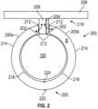
- a nacelle 200that extends circumferentially around the hybrid electric propulsion system 100 (including gas turbine engine 20 ) and at least partially encloses the hybrid electric propulsion system 100 .
- the nacelle 200is configured to at least partially define the bypass flowpath B.
- the nacelle 200includes a first nacelle half 200 a and a second nacelle half 200 b located at opposite lateral sides of the hybrid electric propulsion system 100 .
- the nacelle 200includes an upper bifurcation 202 separating the first nacelle half 200 a and the second nacelle half 200 b , and through which pathways 204 for electrical power, fluids, fuel or the like are routed.
- the upper bifurcation 202houses a pylon 208 by which the hybrid electric propulsion system 100 is attached to an aircraft structure, such as a wing 209 or another engine mounting surface (e.g., fuselage, empennage, etc.).
- the nacelle 200includes an outer nacelle sleeve 214 and an inner nacelle sleeve 216 located radially inboard of and spaced apart from the outer nacelle sleeve 214 .
- the outer nacelle sleeve 214 and the inner nacelle sleeve 216are independently movable about an outer sleeve hinge 212 and an inner sleeve hinge 213 , respectively, between a closed position enclosing the hybrid electric propulsion system 100 and an opened position allowing access to the hybrid electric propulsion system 100 by, for example, a service technician.
- the first nacelle half 200 a and the second nacelle half 200 beach include an outer nacelle sleeve 214 and an inner nacelle sleeve 216 defining the bypass flowpath B therebetween.
- the upper bifurcation 202extends between the outer nacelle sleeve 214 and the inner nacelle sleeve 216 at an upper nacelle end 218 closest to the pylon 208 .
- the outer nacelle sleeves 214are secured to one another by an outer nacelle latch 222
- the inner nacelle sleeves 216are secured to one another by an inner nacelle latch 224 .
- the nacelle 200is absent a lower bifurcation, such that the bypass flowpath B extends circumferentially continuously between the upper bifurcation 202 of the first nacelle half 200 a and the upper bifurcation 202 of the second nacelle half 200 b.
- an anti-ice system 226is operably connected to the nacelle 200 and the hybrid electric propulsion system 100 to prevent ice accumulation on the nacelle 200 and the hybrid electric propulsion system 100 (e.g., gas turbine engine 20 ).
- the anti-ice system 226uses resistive heating elements 228 operably connected to the hybrid electric propulsion system 100 , which provides electrical power to the resistive heating elements 228 .
- the resistive heating elements 228may be powered by, for example, the battery 180 or the electric motor 182 , which may be co-located with the gas turbine engine 20 inside of the nacelle 200 , or may alternatively be located remotely from the nacelle 200 at another location on the aircraft.
- the resistive heating elements 228are arrayed around the nacelle 200 and at selected components of the gas turbine engine 20 , such that when the resistive heating elements 228 are activated and heated, the temperature of the portions of the nacelle 200 and the selected components of the gas turbine engine 20 increases to prevent accumulation of ice at those locations.
- the resistive heating elements 228are formed from a highly electrically-conductive material, such as for example, carbon nanotubes.
- the resistive heating elements 228are located at an inlet end 230 of the outer nacelle sleeve 214 and are arrayed around a circumference or perimeter of the inlet end 230 .
- the outer nacelle sleeve 214is formed from a composite material, such as a carbon fiber or glass fiber reinforced material. In such embodiments, the carbon nanotubes or other highly electrically-conductive material is embedded in the composite material.
- the efficient carbon nano tube anti-ice deviceutilizes less energy than traditional pneumatic systems, but if extra electrical components are being added just for this purpose, much or all of the benefit is negated by the added weight. In the case of a hybrid-electric system, however, the required electrical components are already in place and compensated by other benefits.
Landscapes
- Engineering & Computer Science (AREA)
- Aviation & Aerospace Engineering (AREA)
- Mechanical Engineering (AREA)
- General Engineering & Computer Science (AREA)
- Chemical & Material Sciences (AREA)
- Combustion & Propulsion (AREA)
- Structures Of Non-Positive Displacement Pumps (AREA)
Abstract
Description
Claims (17)
Priority Applications (2)
| Application Number | Priority Date | Filing Date | Title |
|---|---|---|---|
| US18/163,676US12351323B2 (en) | 2023-02-02 | 2023-02-02 | Hybrid electric engine and nacelle system |
| EP24155383.3AEP4421299A3 (en) | 2023-02-02 | 2024-02-01 | Hybrid electric engine and nacelle system |
Applications Claiming Priority (1)
| Application Number | Priority Date | Filing Date | Title |
|---|---|---|---|
| US18/163,676US12351323B2 (en) | 2023-02-02 | 2023-02-02 | Hybrid electric engine and nacelle system |
Publications (2)
| Publication Number | Publication Date |
|---|---|
| US20240262515A1 US20240262515A1 (en) | 2024-08-08 |
| US12351323B2true US12351323B2 (en) | 2025-07-08 |
Family
ID=89834292
Family Applications (1)
| Application Number | Title | Priority Date | Filing Date |
|---|---|---|---|
| US18/163,676Active2043-04-12US12351323B2 (en) | 2023-02-02 | 2023-02-02 | Hybrid electric engine and nacelle system |
Country Status (2)
| Country | Link |
|---|---|
| US (1) | US12351323B2 (en) |
| EP (1) | EP4421299A3 (en) |
Families Citing this family (1)
| Publication number | Priority date | Publication date | Assignee | Title |
|---|---|---|---|---|
| US12351323B2 (en)* | 2023-02-02 | 2025-07-08 | Rtx Corporation | Hybrid electric engine and nacelle system |
Citations (57)
| Publication number | Priority date | Publication date | Assignee | Title |
|---|---|---|---|---|
| US20050038418A1 (en)* | 1997-05-15 | 2005-02-17 | Palomar Medical Technologies, Inc. | Light energy delivery head |
| US20080087371A1 (en)* | 2006-10-11 | 2008-04-17 | Ameron International Corporation | Fiber reinforced resin polymer mortar pole |
| US20110016778A1 (en) | 2008-01-09 | 2011-01-27 | Boris Anatolievich Musokhranov | Method for forming coal mixtures for producing coking burden and a composition of said mixtures |
| US20110167781A1 (en) | 2009-12-30 | 2011-07-14 | Mra Systems, Inc. | Turbomachine nacelle and anti-icing system and method therefor |
| US20130043342A1 (en)* | 2010-01-14 | 2013-02-21 | Saab Ab | Multifunctional de-icing/anti-icing system |
| US20140034414A1 (en)* | 2012-07-31 | 2014-02-06 | Brian Bobby Burkett | Electric heater for integration into an aircraft acoustic panel |
| US20150098810A1 (en)* | 2013-10-07 | 2015-04-09 | Rohr, Inc. | Hybrid inner fixed structure with metallic and composite construction |
| US20150143796A1 (en)* | 2013-11-27 | 2015-05-28 | Rohr, Inc. | System and method for captured inner fixed structure |
| US20150308291A1 (en)* | 2014-04-25 | 2015-10-29 | Rohr, Inc. | Access panel(s) for an inner nacelle of a turbine engine |
| US20160069297A1 (en)* | 2013-04-24 | 2016-03-10 | United Technoligies Corporation | Geared turbine engine with o-duct and thrust reverser |
| US20160201600A1 (en)* | 2013-08-28 | 2016-07-14 | United Tecnologies Corporation | Thrust reverser sliding door assembly |
| US9567089B2 (en)* | 2012-07-24 | 2017-02-14 | Rohr, Inc. | Hybrid hinge and latch beam |
| US9714627B2 (en)* | 2013-11-15 | 2017-07-25 | Rohr, Inc. | Mounting of aircraft propulsion system outer sleeve and inner structure to pylon with distinct hinges |
| US20170240288A1 (en)* | 2016-02-23 | 2017-08-24 | Airbus Operations Sas | Aircraft engine assembly, comprising an engine attachment device equipped with structural movable cowls connected to the central box |
| US9783313B2 (en)* | 2015-06-23 | 2017-10-10 | Rohr, Inc. | Installing or removing aircraft engines |
| US20170362957A1 (en)* | 2016-06-17 | 2017-12-21 | Rohr, Inc. | Nacelle with bifurcation extension and integral structural reinforcement |
| US9897007B2 (en)* | 2012-07-24 | 2018-02-20 | Rohr, Inc. | Thrust reverser-integrated track beam and inner fixed structure |
| US9903313B2 (en)* | 2014-04-24 | 2018-02-27 | Rohr, Inc. | Thrust reverser with one or more butressing corner cascade portions |
| US10006375B1 (en)* | 2017-07-11 | 2018-06-26 | General Electric Company | Propulsion system for an aircraft |
| US10093429B2 (en)* | 2015-07-07 | 2018-10-09 | Rohr, Inc | Latch beam deflection support |
| US10107191B2 (en)* | 2012-02-29 | 2018-10-23 | United Technologies Corporation | Geared gas turbine engine with reduced fan noise |
| US10167741B2 (en)* | 2015-11-03 | 2019-01-01 | Rohr, Inc. | Nacelle fluid drain |
| US20190316545A1 (en) | 2016-11-30 | 2019-10-17 | Safran Nacelles | Aircraft turbojet engine nacelle, propulsion unit and aircraft including such a nacelle |
| US10507931B2 (en)* | 2015-10-19 | 2019-12-17 | Rohr, Inc. | Panel and insert for corner radii |
| US20190389589A1 (en)* | 2018-06-22 | 2019-12-26 | General Electric Company | Anti-icing system for an aircraft |
| US10734953B1 (en)* | 2019-02-22 | 2020-08-04 | Qorvo Us, Inc. | Power amplifier system |
| US10759541B2 (en)* | 2016-10-14 | 2020-09-01 | Rohr, Inc. | Nacelle bifurcation with leading edge structure |
| US20200392859A1 (en) | 2019-06-12 | 2020-12-17 | Rolls-Royce Plc | Limiting spool speeds in a gas turbine engine |
| US20210003096A1 (en)* | 2017-11-27 | 2021-01-07 | Safran Nacelles | Turbojet engine nacelle including a single movable frame of a cascade thrust reverser and passages of ancillaries |
| US20210129998A1 (en)* | 2018-03-29 | 2021-05-06 | Gkn Aerospace Services Limited | Ice removal system |
| US20210172333A1 (en)* | 2019-12-06 | 2021-06-10 | United Technologies Corporation | Systems and methods for hybrid electric turbine engines |
| US20210231057A1 (en)* | 2020-01-28 | 2021-07-29 | Airbus Operations Sas | Aircraft turbomachine equipped with a thermoacoustic system |
| US20210310440A1 (en)* | 2020-04-07 | 2021-10-07 | Rohr, Inc. | Nacelle with independent opening thrust reverser section |
| US20210316872A1 (en)* | 2019-10-08 | 2021-10-14 | Rohr , Inc. | Support structure for inner cowls of an aircraft propulsion system |
| US20210323685A1 (en)* | 2020-04-17 | 2021-10-21 | Raytheon Technologies Corporation | Systems and methods for hybrid electric gas turbine engines |
| US11208970B2 (en)* | 2018-06-28 | 2021-12-28 | Rohr, Inc. | Aft cascade ring design concept |
| US11261787B2 (en)* | 2018-06-22 | 2022-03-01 | General Electric Company | Aircraft anti-icing system |
| US11428190B2 (en)* | 2017-12-28 | 2022-08-30 | Safran Nacelles | Grid-type thrust reverser for turbojet engine |
| US20220348341A1 (en)* | 2021-04-30 | 2022-11-03 | Raytheon Technologies Corporation | Hybrid propulsion control system update module |
| US20220403776A1 (en)* | 2021-06-18 | 2022-12-22 | Raytheon Technologies Corporation | Turbine over-speed brake for hybrid electric gas turbine engine |
| US20220412268A1 (en)* | 2021-06-28 | 2022-12-29 | Raytheon Technologies Corporation | Hybrid electric multiple shaft core |
| US11548648B2 (en)* | 2020-01-14 | 2023-01-10 | Goodrich Corporation | Robust power transmission |
| US11618574B2 (en)* | 2018-06-19 | 2023-04-04 | Airbus Operations Gmbh | Heatable leading-edge apparatus, leading-edge heating system and aircraft comprising them |
| US20230139529A1 (en)* | 2021-10-29 | 2023-05-04 | Raytheon Technologies Corporation | Hybrid-electric single engine descent failure management |
| US20230138442A1 (en)* | 2021-10-29 | 2023-05-04 | Raytheon Technologies Corporation | Hybrid-electric single engine descent failure management |
| US20230211889A1 (en)* | 2022-01-05 | 2023-07-06 | General Electric Company | Aircraft thrust management with a fuel cell |
| US11698032B1 (en)* | 2022-05-06 | 2023-07-11 | Pratt & Whitney Canada Corp. | Systems and methods for controlling noise in aircraft powered by hybrid-electric gas turbine engines |
| US11706848B2 (en)* | 2014-04-10 | 2023-07-18 | Metis Design Corporation | Multifunctional assemblies |
| US11725542B2 (en)* | 2021-07-29 | 2023-08-15 | Pratt & Whitney Canada Corp. | Gas turbine engine disassembly / assembly methods |
| US20230282848A1 (en)* | 2022-02-21 | 2023-09-07 | General Electric Company | Modular fuel cell assembly |
| US11753968B2 (en)* | 2021-08-23 | 2023-09-12 | Rolls-Royce Deutschland Ltd & Co Kg | Nacelle cowling structure for a turbomachine |
| US20240025556A1 (en)* | 2022-07-19 | 2024-01-25 | Blended Wing Aircraft, Inc. | Methods and systems for venting a fuel tank on a blended wing body aircraft |
| US11891185B2 (en)* | 2020-05-20 | 2024-02-06 | Safran Nacelles | Nacelle for a propulsion assembly with a very high bypass ratio, comprising a removable and structural front internal structure |
| US20240061444A1 (en)* | 2022-08-17 | 2024-02-22 | Beta Air, Llc | Apparatus for pre-flight preparation for an electric aircraft |
| US11964768B2 (en)* | 2017-09-01 | 2024-04-23 | Textron Innovations Inc. | Tailored rotor-blade ice-protection system |
| US20240174368A1 (en)* | 2022-11-30 | 2024-05-30 | Airbus Operations Sas | Propeller propulsion assembly for an aircraft |
| US20240262515A1 (en)* | 2023-02-02 | 2024-08-08 | Raytheon Technologies Corporation | Hybrid electric engine and nacelle system |
- 2023
- 2023-02-02USUS18/163,676patent/US12351323B2/enactiveActive
- 2024
- 2024-02-01EPEP24155383.3Apatent/EP4421299A3/enactivePending
Patent Citations (62)
| Publication number | Priority date | Publication date | Assignee | Title |
|---|---|---|---|---|
| US20050038418A1 (en)* | 1997-05-15 | 2005-02-17 | Palomar Medical Technologies, Inc. | Light energy delivery head |
| US20080087371A1 (en)* | 2006-10-11 | 2008-04-17 | Ameron International Corporation | Fiber reinforced resin polymer mortar pole |
| US20110016778A1 (en) | 2008-01-09 | 2011-01-27 | Boris Anatolievich Musokhranov | Method for forming coal mixtures for producing coking burden and a composition of said mixtures |
| US20110167781A1 (en) | 2009-12-30 | 2011-07-14 | Mra Systems, Inc. | Turbomachine nacelle and anti-icing system and method therefor |
| US8931740B2 (en)* | 2010-01-14 | 2015-01-13 | Saab Ab | Multifunctional de-icing/anti-icing system |
| US20130043342A1 (en)* | 2010-01-14 | 2013-02-21 | Saab Ab | Multifunctional de-icing/anti-icing system |
| US10107191B2 (en)* | 2012-02-29 | 2018-10-23 | United Technologies Corporation | Geared gas turbine engine with reduced fan noise |
| US9897007B2 (en)* | 2012-07-24 | 2018-02-20 | Rohr, Inc. | Thrust reverser-integrated track beam and inner fixed structure |
| US9567089B2 (en)* | 2012-07-24 | 2017-02-14 | Rohr, Inc. | Hybrid hinge and latch beam |
| US20140034414A1 (en)* | 2012-07-31 | 2014-02-06 | Brian Bobby Burkett | Electric heater for integration into an aircraft acoustic panel |
| US20160069297A1 (en)* | 2013-04-24 | 2016-03-10 | United Technoligies Corporation | Geared turbine engine with o-duct and thrust reverser |
| US20160201600A1 (en)* | 2013-08-28 | 2016-07-14 | United Tecnologies Corporation | Thrust reverser sliding door assembly |
| US20150098810A1 (en)* | 2013-10-07 | 2015-04-09 | Rohr, Inc. | Hybrid inner fixed structure with metallic and composite construction |
| US9885253B2 (en)* | 2013-10-07 | 2018-02-06 | Rohr, Inc. | Hybrid inner fixed structure with metallic and composite construction |
| US9714627B2 (en)* | 2013-11-15 | 2017-07-25 | Rohr, Inc. | Mounting of aircraft propulsion system outer sleeve and inner structure to pylon with distinct hinges |
| US20150143796A1 (en)* | 2013-11-27 | 2015-05-28 | Rohr, Inc. | System and method for captured inner fixed structure |
| US9366202B2 (en)* | 2013-11-27 | 2016-06-14 | Rohr, Inc. | System and method for captured inner fixed structure |
| US11706848B2 (en)* | 2014-04-10 | 2023-07-18 | Metis Design Corporation | Multifunctional assemblies |
| US9903313B2 (en)* | 2014-04-24 | 2018-02-27 | Rohr, Inc. | Thrust reverser with one or more butressing corner cascade portions |
| US20150308291A1 (en)* | 2014-04-25 | 2015-10-29 | Rohr, Inc. | Access panel(s) for an inner nacelle of a turbine engine |
| US9783313B2 (en)* | 2015-06-23 | 2017-10-10 | Rohr, Inc. | Installing or removing aircraft engines |
| US10093429B2 (en)* | 2015-07-07 | 2018-10-09 | Rohr, Inc | Latch beam deflection support |
| US10507931B2 (en)* | 2015-10-19 | 2019-12-17 | Rohr, Inc. | Panel and insert for corner radii |
| US10167741B2 (en)* | 2015-11-03 | 2019-01-01 | Rohr, Inc. | Nacelle fluid drain |
| US20170240288A1 (en)* | 2016-02-23 | 2017-08-24 | Airbus Operations Sas | Aircraft engine assembly, comprising an engine attachment device equipped with structural movable cowls connected to the central box |
| US20170362957A1 (en)* | 2016-06-17 | 2017-12-21 | Rohr, Inc. | Nacelle with bifurcation extension and integral structural reinforcement |
| US10759541B2 (en)* | 2016-10-14 | 2020-09-01 | Rohr, Inc. | Nacelle bifurcation with leading edge structure |
| US20190316545A1 (en) | 2016-11-30 | 2019-10-17 | Safran Nacelles | Aircraft turbojet engine nacelle, propulsion unit and aircraft including such a nacelle |
| US10006375B1 (en)* | 2017-07-11 | 2018-06-26 | General Electric Company | Propulsion system for an aircraft |
| US11964768B2 (en)* | 2017-09-01 | 2024-04-23 | Textron Innovations Inc. | Tailored rotor-blade ice-protection system |
| US20210003096A1 (en)* | 2017-11-27 | 2021-01-07 | Safran Nacelles | Turbojet engine nacelle including a single movable frame of a cascade thrust reverser and passages of ancillaries |
| US11428190B2 (en)* | 2017-12-28 | 2022-08-30 | Safran Nacelles | Grid-type thrust reverser for turbojet engine |
| US20210129998A1 (en)* | 2018-03-29 | 2021-05-06 | Gkn Aerospace Services Limited | Ice removal system |
| US12030648B2 (en)* | 2018-03-29 | 2024-07-09 | Gkn Aerospace Services Limited | Ice removal system |
| US11618574B2 (en)* | 2018-06-19 | 2023-04-04 | Airbus Operations Gmbh | Heatable leading-edge apparatus, leading-edge heating system and aircraft comprising them |
| US20190389589A1 (en)* | 2018-06-22 | 2019-12-26 | General Electric Company | Anti-icing system for an aircraft |
| US11242150B2 (en)* | 2018-06-22 | 2022-02-08 | General Electric Company | Anti-icing system for an aircraft |
| US11261787B2 (en)* | 2018-06-22 | 2022-03-01 | General Electric Company | Aircraft anti-icing system |
| US11208970B2 (en)* | 2018-06-28 | 2021-12-28 | Rohr, Inc. | Aft cascade ring design concept |
| US10734953B1 (en)* | 2019-02-22 | 2020-08-04 | Qorvo Us, Inc. | Power amplifier system |
| US20200392859A1 (en) | 2019-06-12 | 2020-12-17 | Rolls-Royce Plc | Limiting spool speeds in a gas turbine engine |
| US20210316872A1 (en)* | 2019-10-08 | 2021-10-14 | Rohr , Inc. | Support structure for inner cowls of an aircraft propulsion system |
| US20210172333A1 (en)* | 2019-12-06 | 2021-06-10 | United Technologies Corporation | Systems and methods for hybrid electric turbine engines |
| US11548648B2 (en)* | 2020-01-14 | 2023-01-10 | Goodrich Corporation | Robust power transmission |
| US20210231057A1 (en)* | 2020-01-28 | 2021-07-29 | Airbus Operations Sas | Aircraft turbomachine equipped with a thermoacoustic system |
| US20210310440A1 (en)* | 2020-04-07 | 2021-10-07 | Rohr, Inc. | Nacelle with independent opening thrust reverser section |
| US20210323685A1 (en)* | 2020-04-17 | 2021-10-21 | Raytheon Technologies Corporation | Systems and methods for hybrid electric gas turbine engines |
| US11891185B2 (en)* | 2020-05-20 | 2024-02-06 | Safran Nacelles | Nacelle for a propulsion assembly with a very high bypass ratio, comprising a removable and structural front internal structure |
| US20220348341A1 (en)* | 2021-04-30 | 2022-11-03 | Raytheon Technologies Corporation | Hybrid propulsion control system update module |
| US20220403776A1 (en)* | 2021-06-18 | 2022-12-22 | Raytheon Technologies Corporation | Turbine over-speed brake for hybrid electric gas turbine engine |
| US20220412268A1 (en)* | 2021-06-28 | 2022-12-29 | Raytheon Technologies Corporation | Hybrid electric multiple shaft core |
| US11725542B2 (en)* | 2021-07-29 | 2023-08-15 | Pratt & Whitney Canada Corp. | Gas turbine engine disassembly / assembly methods |
| US11753968B2 (en)* | 2021-08-23 | 2023-09-12 | Rolls-Royce Deutschland Ltd & Co Kg | Nacelle cowling structure for a turbomachine |
| US20230138442A1 (en)* | 2021-10-29 | 2023-05-04 | Raytheon Technologies Corporation | Hybrid-electric single engine descent failure management |
| US20230139529A1 (en)* | 2021-10-29 | 2023-05-04 | Raytheon Technologies Corporation | Hybrid-electric single engine descent failure management |
| US20230211889A1 (en)* | 2022-01-05 | 2023-07-06 | General Electric Company | Aircraft thrust management with a fuel cell |
| US20230282848A1 (en)* | 2022-02-21 | 2023-09-07 | General Electric Company | Modular fuel cell assembly |
| US11698032B1 (en)* | 2022-05-06 | 2023-07-11 | Pratt & Whitney Canada Corp. | Systems and methods for controlling noise in aircraft powered by hybrid-electric gas turbine engines |
| US20240025556A1 (en)* | 2022-07-19 | 2024-01-25 | Blended Wing Aircraft, Inc. | Methods and systems for venting a fuel tank on a blended wing body aircraft |
| US20240061444A1 (en)* | 2022-08-17 | 2024-02-22 | Beta Air, Llc | Apparatus for pre-flight preparation for an electric aircraft |
| US20240174368A1 (en)* | 2022-11-30 | 2024-05-30 | Airbus Operations Sas | Propeller propulsion assembly for an aircraft |
| US20240262515A1 (en)* | 2023-02-02 | 2024-08-08 | Raytheon Technologies Corporation | Hybrid electric engine and nacelle system |
Non-Patent Citations (2)
| Title |
|---|
| Extended European Search Report for EP Application No. 24155383.3, dated Sep. 25, 2024, pp. 1-11. |
| Partial European Search Report for EP Application No. 24155383.3; Mailing Date, Jul. 3, 2024. |
Also Published As
| Publication number | Publication date |
|---|---|
| EP4421299A3 (en) | 2024-10-23 |
| EP4421299A2 (en) | 2024-08-28 |
| US20240262515A1 (en) | 2024-08-08 |
Similar Documents
| Publication | Publication Date | Title |
|---|---|---|
| US11821369B2 (en) | Electric power assist for in-flight engine re-start | |
| US10710735B2 (en) | Operation of a vertical takeoff and landing aircraft | |
| EP3862542B1 (en) | Cooling system for power cables in a gas turbine engine | |
| US20190002113A1 (en) | Propulsion system for an aircraft | |
| US20230182919A1 (en) | Propulsion system for an aircraft | |
| US12092042B2 (en) | Hydrogen fuel system | |
| US12092038B2 (en) | Rotor dynamics accommodation using electrical power assist | |
| US20180372588A1 (en) | Propulsion system for an aircraft | |
| US11199139B2 (en) | Gas turbine engine system bowed rotor start mitigation and wear reduction | |
| EP4352349B1 (en) | Oil circulation system for hybrid electric engine | |
| US12123344B2 (en) | Engine and secondary power unit integrated operation | |
| US20220396365A1 (en) | Hybrid electric engine power distribution | |
| EP3767090B1 (en) | Compressor operability control for hybrid electric propulsion | |
| EP4421299A2 (en) | Hybrid electric engine and nacelle system | |
| US20220397064A1 (en) | Hybrid electric engine with electric tip clearance mechanism | |
| EP4112909A1 (en) | Hybrid electric variable area turbine | |
| US12258139B2 (en) | Ground-based aircraft movement | |
| US11415065B2 (en) | Material fatigue improvement for hybrid propulsion systems | |
| US20230095723A1 (en) | Turbine engine with variable pitch fan | |
| EP3869022B1 (en) | After-fan system with electrical motor for gas turbine engines | |
| US11557995B2 (en) | Aircraft engine power-assist start stability control | |
| EP3502442B1 (en) | Concentric power takeoff transmission | |
| EP3034838B1 (en) | System and method for controlling an environmental condition of an engine electronic component | |
| US11649763B1 (en) | Rating control architecture and method for hybrid electric engine | |
| US20240401518A1 (en) | Hydrogen fuel system |
Legal Events
| Date | Code | Title | Description |
|---|---|---|---|
| FEPP | Fee payment procedure | Free format text:ENTITY STATUS SET TO UNDISCOUNTED (ORIGINAL EVENT CODE: BIG.); ENTITY STATUS OF PATENT OWNER: LARGE ENTITY | |
| AS | Assignment | Owner name:ROHR, INC., CALIFORNIA Free format text:ASSIGNMENT OF ASSIGNORS INTEREST;ASSIGNOR:SHERMAN, BRIAN;REEL/FRAME:062579/0207 Effective date:20230131 Owner name:RAYTHEON TECHNOLOGIES CORPORATION, CONNECTICUT Free format text:ASSIGNMENT OF ASSIGNORS INTEREST;ASSIGNORS:MULDOON, MARC J.;YAZICI, MURAT;REEL/FRAME:062579/0182 Effective date:20230131 | |
| AS | Assignment | Owner name:RTX CORPORATION, CONNECTICUT Free format text:CHANGE OF NAME;ASSIGNOR:RAYTHEON TECHNOLOGIES CORPORATION;REEL/FRAME:064402/0837 Effective date:20230714 | |
| STPP | Information on status: patent application and granting procedure in general | Free format text:NON FINAL ACTION MAILED | |
| STPP | Information on status: patent application and granting procedure in general | Free format text:RESPONSE TO NON-FINAL OFFICE ACTION ENTERED AND FORWARDED TO EXAMINER | |
| STPP | Information on status: patent application and granting procedure in general | Free format text:FINAL REJECTION MAILED | |
| AS | Assignment | Owner name:RTX CORPORATION, CONNECTICUT Free format text:CHANGE OF NAME;ASSIGNOR:RAYTHEON TECHNOLOGIES CORPORATION;REEL/FRAME:071429/0761 Effective date:20230711 | |
| STCF | Information on status: patent grant | Free format text:PATENTED CASE |