US12350754B2 - Electron beam source and the use of the same - Google Patents
Electron beam source and the use of the sameDownload PDFInfo
- Publication number
- US12350754B2 US12350754B2US16/195,995US201816195995AUS12350754B2US 12350754 B2US12350754 B2US 12350754B2US 201816195995 AUS201816195995 AUS 201816195995AUS 12350754 B2US12350754 B2US 12350754B2
- Authority
- US
- United States
- Prior art keywords
- electron beam
- top surface
- base
- cathode
- grid
- Prior art date
- Legal status (The legal status is an assumption and is not a legal conclusion. Google has not performed a legal analysis and makes no representation as to the accuracy of the status listed.)
- Active, expires
Links
Images


Classifications
- B—PERFORMING OPERATIONS; TRANSPORTING
- B23—MACHINE TOOLS; METAL-WORKING NOT OTHERWISE PROVIDED FOR
- B23K—SOLDERING OR UNSOLDERING; WELDING; CLADDING OR PLATING BY SOLDERING OR WELDING; CUTTING BY APPLYING HEAT LOCALLY, e.g. FLAME CUTTING; WORKING BY LASER BEAM
- B23K15/00—Electron-beam welding or cutting
- B23K15/0046—Welding
- B23K15/0086—Welding welding for purposes other than joining, e.g. built-up welding
- B—PERFORMING OPERATIONS; TRANSPORTING
- B29—WORKING OF PLASTICS; WORKING OF SUBSTANCES IN A PLASTIC STATE IN GENERAL
- B29C—SHAPING OR JOINING OF PLASTICS; SHAPING OF MATERIAL IN A PLASTIC STATE, NOT OTHERWISE PROVIDED FOR; AFTER-TREATMENT OF THE SHAPED PRODUCTS, e.g. REPAIRING
- B29C64/00—Additive manufacturing, i.e. manufacturing of three-dimensional [3D] objects by additive deposition, additive agglomeration or additive layering, e.g. by 3D printing, stereolithography or selective laser sintering
- B29C64/10—Processes of additive manufacturing
- B29C64/141—Processes of additive manufacturing using only solid materials
- B29C64/153—Processes of additive manufacturing using only solid materials using layers of powder being selectively joined, e.g. by selective laser sintering or melting
- B—PERFORMING OPERATIONS; TRANSPORTING
- B29—WORKING OF PLASTICS; WORKING OF SUBSTANCES IN A PLASTIC STATE IN GENERAL
- B29C—SHAPING OR JOINING OF PLASTICS; SHAPING OF MATERIAL IN A PLASTIC STATE, NOT OTHERWISE PROVIDED FOR; AFTER-TREATMENT OF THE SHAPED PRODUCTS, e.g. REPAIRING
- B29C64/00—Additive manufacturing, i.e. manufacturing of three-dimensional [3D] objects by additive deposition, additive agglomeration or additive layering, e.g. by 3D printing, stereolithography or selective laser sintering
- B29C64/20—Apparatus for additive manufacturing; Details thereof or accessories therefor
- B29C64/264—Arrangements for irradiation
- B29C64/268—Arrangements for irradiation using laser beams; using electron beams [EB]
- B—PERFORMING OPERATIONS; TRANSPORTING
- B33—ADDITIVE MANUFACTURING TECHNOLOGY
- B33Y—ADDITIVE MANUFACTURING, i.e. MANUFACTURING OF THREE-DIMENSIONAL [3-D] OBJECTS BY ADDITIVE DEPOSITION, ADDITIVE AGGLOMERATION OR ADDITIVE LAYERING, e.g. BY 3-D PRINTING, STEREOLITHOGRAPHY OR SELECTIVE LASER SINTERING
- B33Y10/00—Processes of additive manufacturing
- B—PERFORMING OPERATIONS; TRANSPORTING
- B33—ADDITIVE MANUFACTURING TECHNOLOGY
- B33Y—ADDITIVE MANUFACTURING, i.e. MANUFACTURING OF THREE-DIMENSIONAL [3-D] OBJECTS BY ADDITIVE DEPOSITION, ADDITIVE AGGLOMERATION OR ADDITIVE LAYERING, e.g. BY 3-D PRINTING, STEREOLITHOGRAPHY OR SELECTIVE LASER SINTERING
- B33Y30/00—Apparatus for additive manufacturing; Details thereof or accessories therefor
- B—PERFORMING OPERATIONS; TRANSPORTING
- B33—ADDITIVE MANUFACTURING TECHNOLOGY
- B33Y—ADDITIVE MANUFACTURING, i.e. MANUFACTURING OF THREE-DIMENSIONAL [3-D] OBJECTS BY ADDITIVE DEPOSITION, ADDITIVE AGGLOMERATION OR ADDITIVE LAYERING, e.g. BY 3-D PRINTING, STEREOLITHOGRAPHY OR SELECTIVE LASER SINTERING
- B33Y50/00—Data acquisition or data processing for additive manufacturing
- B33Y50/02—Data acquisition or data processing for additive manufacturing for controlling or regulating additive manufacturing processes
- H—ELECTRICITY
- H01—ELECTRIC ELEMENTS
- H01J—ELECTRIC DISCHARGE TUBES OR DISCHARGE LAMPS
- H01J1/00—Details of electrodes, of magnetic control means, of screens, or of the mounting or spacing thereof, common to two or more basic types of discharge tubes or lamps
- H01J1/02—Main electrodes
- H01J1/13—Solid thermionic cathodes
- H01J1/135—Circuit arrangements therefor, e.g. for temperature control
- H—ELECTRICITY
- H01—ELECTRIC ELEMENTS
- H01J—ELECTRIC DISCHARGE TUBES OR DISCHARGE LAMPS
- H01J1/00—Details of electrodes, of magnetic control means, of screens, or of the mounting or spacing thereof, common to two or more basic types of discharge tubes or lamps
- H01J1/02—Main electrodes
- H01J1/13—Solid thermionic cathodes
- H01J1/15—Cathodes heated directly by an electric current
- H01J1/16—Cathodes heated directly by an electric current characterised by the shape
- H—ELECTRICITY
- H01—ELECTRIC ELEMENTS
- H01J—ELECTRIC DISCHARGE TUBES OR DISCHARGE LAMPS
- H01J3/00—Details of electron-optical or ion-optical arrangements or of ion traps common to two or more basic types of discharge tubes or lamps
- H01J3/02—Electron guns
- H01J3/027—Construction of the gun or parts thereof
- H—ELECTRICITY
- H01—ELECTRIC ELEMENTS
- H01J—ELECTRIC DISCHARGE TUBES OR DISCHARGE LAMPS
- H01J37/00—Discharge tubes with provision for introducing objects or material to be exposed to the discharge, e.g. for the purpose of examination or processing thereof
- H01J37/30—Electron-beam or ion-beam tubes for localised treatment of objects
- H01J37/302—Controlling tubes by external information, e.g. programme control
- H01J37/3023—Programme control
- H—ELECTRICITY
- H01—ELECTRIC ELEMENTS
- H01J—ELECTRIC DISCHARGE TUBES OR DISCHARGE LAMPS
- H01J37/00—Discharge tubes with provision for introducing objects or material to be exposed to the discharge, e.g. for the purpose of examination or processing thereof
- H01J37/30—Electron-beam or ion-beam tubes for localised treatment of objects
- H01J37/317—Electron-beam or ion-beam tubes for localised treatment of objects for changing properties of the objects or for applying thin layers thereon, e.g. for ion implantation
- H01J37/3178—Electron-beam or ion-beam tubes for localised treatment of objects for changing properties of the objects or for applying thin layers thereon, e.g. for ion implantation for applying thin layers on objects
- Y—GENERAL TAGGING OF NEW TECHNOLOGICAL DEVELOPMENTS; GENERAL TAGGING OF CROSS-SECTIONAL TECHNOLOGIES SPANNING OVER SEVERAL SECTIONS OF THE IPC; TECHNICAL SUBJECTS COVERED BY FORMER USPC CROSS-REFERENCE ART COLLECTIONS [XRACs] AND DIGESTS
- Y02—TECHNOLOGIES OR APPLICATIONS FOR MITIGATION OR ADAPTATION AGAINST CLIMATE CHANGE
- Y02P—CLIMATE CHANGE MITIGATION TECHNOLOGIES IN THE PRODUCTION OR PROCESSING OF GOODS
- Y02P10/00—Technologies related to metal processing
- Y02P10/25—Process efficiency
Definitions
- Various embodiments of the present inventionrelate to an electron generating assembly, an electron beam source and a method for additive manufacturing of a three-dimensional article by successively fusing individual layers of powder material using such electron beam source.
- An additive manufacturing apparatusmay comprise a work table on which the three-dimensional article is to be formed, a powder dispenser or powder distributor, arranged to lay down a thin layer of powder on the work table for the formation of a powder bed, a high energy beam for delivering energy to the powder whereby fusion of the powder takes place, elements for control of the energy given off by the energy beam over the powder bed for the formation of a cross section of the three-dimensional article through fusion of parts of the powder bed, and a controlling computer, in which information is stored concerning consecutive cross sections of the three-dimensional article.
- a three-dimensional articleis formed through consecutive fusions of consecutively formed cross sections of powder layers, successively laid down by the powder dispenser.
- an electron beam sourcefor generating an electron beam comprising a cathode, an anode and a grid for regulating an electron beam current, wherein the cathode is having a base and a protrusion with sidewalls and a top surface, the base having a base surface which is essentially in parallel with the top surface, the base surface and the top surface are essentially flat and facing towards the anode, the base surface and the top surface are arranged at a predetermined distance from each other, the base is larger than the protrusion, the sidewalls are essentially perpendicular to the base surface and the top surface, the electron beam source further comprising a control unit adapted for changing an applied voltage to the grid for switching a spot size of the electron beam on a target surface between at least a first a first spot size corresponding to emission from the top surface of the cathode only and to a second spot size corresponding to emission from the top surface and the base surface of the cathode.
- the base and the protrusionare circular.
- a non-limiting advantage of this embodimentis that any defects in the electron beam spot on the target surface may be easily detected.
- the center of the protrusionis aligned with the center of the base element.
- a non-limiting advantage of this embodimentis that a so called ghost spot may be arranged symmetrically around the melting spot.
- the center of the protrusionis not aligned with the center of the base element.
- the predetermined distance of the top surface and the base surfaceis 0.2-2 mm.
- a non-limiting advantage of this embodimentis that the sensitivity of a change in grid voltage may be chosen by a different distance. The smaller the distance the more sensitive the cathode will be for grid voltage variations, which in turn may result in a different electron beam spot sizes. By increasing the distance more variations in the grid voltage is allowed before changing from only electron beam emanating from the top surface to an electron emanating from the top surface plus the base surface. A larger distance will increase the electron beam current range from only the top surface before the base surface starts to add electrons to the electron beam spot on the target surface.
- an apparatus for forming a three-dimensional article through successively depositing individual layers of powder material that are fused together so as to form the articlewherein the apparatus comprises an electron beam source according to any one of the embodiments mentioned above.
- An advantage of this embodimentis that the electron beam spot may be switched between different spot sizes during manufacturing for different purposes very quickly and without the need of changing the setting of the beam shaping optics.
- an electron beam generating assemblyfor and electron beam source, the assembly comprising a cathode, a grid, a heating circuit for the cathode, the cathode and grid are arranged electrically insulated from each other, wherein the cathode is having a base and a protrusion with sidewalls and a top surface, the base with a base surface and the top surface are essentially in parallel with each other, essentially flat and facing downwards, the base surface and the top surface are arranged at a predetermined distance from each other, the base surface is larger than the top surface and the sidewalls are essentially perpendicular to the base surface and the top surface.
- a non-limiting advantage of the present inventionis that the inventive concept may be used in any existing triode electron beam source with little or no design modifications to the electron beam source as such.
- FIG. 1depicts, in a schematic view, an example embodiment of an electron beam source with an inventive electron beam generating assembly
- FIG. 2depicts, in a schematic view, an example embodiment of an electron beam generating assembly according to the present invention
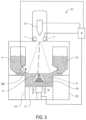
- FIG. 3depicts, in a schematic view, an example embodiment of an apparatus for producing a three-dimensional article which may have an electron beam generating assembly as depicted in FIG. 2 .
- FIG. 4is a block diagram of an exemplary system 1020 according to various embodiments.
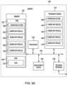
- FIG. 5 Ais a schematic block diagram of a server 1200 according to various embodiments.
- FIG. 5 Bis a schematic block diagram of an exemplary mobile device 1300 according to various embodiments.
- three-dimensional structuresand the like as used herein refer generally to intended or actually fabricated three-dimensional configurations (e.g., of structural material or materials) that are intended to be used for a particular purpose. Such structures, etc. may, for example, be designed with the aid of a three-dimensional CAD system.
- electron beamrefers to any charged particle beam.
- the sources of charged particle beamcan include an electron gun, a linear accelerator and so on.
- FIG. 3depicts an embodiment of a freeform fabrication or additive manufacturing apparatus 21 in which the electron beam generating assembly according to the present invention may be implemented.
- the apparatus 21comprising an electron beam gun 6 ; deflection coils 7 ; two powder hoppers 4 , 14 ; a build platform 2 ; a build tank 10 ; a powder distributor 28 ; a powder bed 5 ; and a vacuum chamber 20 .
- the vacuum chamber 20is capable of maintaining a vacuum environment via a vacuum system, which system may comprise a turbo molecular pump, a scroll pump, an ion pump and one or more valves which are well known to a skilled person in the art and therefore need no further explanation in this context.
- the vacuum systemis controlled by a control unit 8 .
- the electron beam gun 6is generating an electron beam which is used for pre-heating of the powder, melting or fusing together powder material provided on the build platform 2 or post heat treatment of the already fused powder material.
- the control unit 8may be used for controlling and managing the electron beam emitted from the electron beam gun 6 .
- At least one focusing coil (not shown), at least one deflection coil 7 , an optional coil for astigmatic correction (not shown) and an electron beam power supply (not shown)may be electrically connected to the control unit 8 .
- the electron beam gun 6may generate a focusable electron beam with an accelerating voltage of about 15-60 kV and with a beam power in the range of 3-10 kW.
- the pressure in the vacuum chambermay be 1 ⁇ 10 ⁇ 3 mbar or lower when building the three-dimensional article by fusing the powder layer by layer with the energy beam.
- the powder hoppers 4 , 14comprise the powder material to be provided on the build platform 2 in the build tank 10 .
- the powder materialmay for instance be pure metals or metal alloys such as titanium, titanium alloys, aluminum, aluminum alloys, stainless steel, Co—Cr alloys, nickel based super alloys, etc.
- the powder distributor 28is arranged to lay down a thin layer of the powder material on the build platform 2 .
- the build platform 2will be lowered successively in relation to a fixed point in the vacuum chamber.
- the build platform 2is in one embodiment of the invention arranged movably in vertical direction, i.e., in the direction indicated by arrow P. This means that the build platform 2 starts in an initial position, in which a first powder material layer of necessary thickness has been laid down.
- Means for lowering the build platform 2may for instance be through a servo engine equipped with a gear, adjusting screws, etc.
- the servo enginemay be connected to the control unit 8 .
- the energy beamis directed over the work table causing the second powder layer to fuse in selected locations to form a second cross section of the three-dimensional article.
- Fused portions in the second layermay be bonded to fused portions of the first layer.
- the fused portions in the first and second layermay be melted together by melting not only the powder in the uppermost layer but also remelting at least a fraction of a thickness of a layer directly below the uppermost layer.
- the electrical conductivity of the powdercan gradually be increased by increasing the temperature of the powder.
- a powder that has a high temperatureobtains a considerably higher conductivity which results in a lower density of the charge distribution since the charges quickly can diffuse over a large region. This effect is enhanced if the powder is allowed to be slightly sintered during a pre-heating process.
- the powdercan be fused together, i.e., melted or fully sintered, with predetermined values of the beam current and beam scanning velocity.
- FIG. 1depicts, in a schematic view, an exemplary embodiment of an electron beam source in which the inventive method may be implemented.
- the electron beam source 100comprises a cathode 102 , a grid 104 and an anode 106 . Electrons emitted at the cathode 102 being on negative potential are accelerated towards the anode 106 and finally a target surface 118 .
- a grid 104is set at a predetermined distance from the cathode 102 .
- the cathode 102may be provided with a voltage which may cause the cathode to heat up, where upon the cathode 102 releases electrons by thermionic emission.
- An aperture 105 of the grid 104may have about the same size and shape as a cross sectional area of the cathode along a plane taken along a line denote by A-A.
- An electron beam generating cathodemay be a thermionic cathode made of an alkaline earth metal hexaboride such as Lithium hexaboride, Sodium hexaboride, Potassium hexaboride, Rubidium hexaboride, Caesium hexaboride or Francium hexaboride.
- an alkaline earth metal hexaboridesuch as Lithium hexaboride, Sodium hexaboride, Potassium hexaboride, Rubidium hexaboride, Caesium hexaboride or Francium hexaboride.
- the cathodemay also be made of a rare earth metal hexaboride such as Scandium hexaboride, Yttrium hexaboride, Lanthanum hexaboride, Cerium hexaboride, Praseodymium hexaboride, Neodymium hexaboride, Promethium hexaboride, Samarium hexaboride, Europium hexaboride, Gadolumium hexaboride, Terbium hexaboride, Dysprosium hexaboride, Holmium hexaboride, Erbium hexaboride, Thulium hexaboride, Ytterbium hexaboride or Lutetium hexaboride.
- the cathodemay also be made of Hafnium carbide.
- the grid 104is provided between the cathode 102 and the anode 106 .
- the grid 104may be arranged as a plate having the aperture 105 .
- the aperture 105may be aligned with the cathode 102 .
- the size of the aperture in the grid 104may correspond to a cross section of the electron beam 120 at the position of the grid 104 .
- a grid voltage 180may be provided between the grid 104 and the cathode 102 and may be adjusted between a negative blocking voltage and a full power voltage and thereby adjusting an electron beam current between 0—maximum electron beam current.
- the cathode 102may be provided with a negative potential of ⁇ 20 kV to ⁇ 100 kV.
- a first connection point 110 of the accelerator voltage 160 and a first connection point 114 of the grid voltage 180may be fixed to the same potential of ⁇ 20 kV to ⁇ 100 kV.
- a second connection point 108 of the accelerator voltage 160may be provided with ground potential.
- a second connection point 112 of the grid voltage 180may be varied between the negative blocking voltage and the full power voltage.
- a second control unit 150may be controlling the voltage on the second connection point 112 of the grid voltage in order to adjust the electron beam current to a desired value.
- the second control unit 150may be a physically separate control unit in connection with the control unit 8 or fully integrated in the control unit 8 .
- the target surface 118may be set to ground potential or a positive potential.
- the electron beam source 100may also comprise means 170 for detecting the actual electron beam current.
- An example means for detecting the electron beam current on the target surfacemay be to detect the actual loading of the high voltage source providing the accelerator voltage 160 , indicated by box 170 in FIG. 1 . This may be done by simply measuring the electron beam passing between the first and second connection points 110 and 108 respectively.
- the negative blocking voltagemay be around ⁇ 61 kV, i.e., the second connection point 112 of the grid voltage is set at ⁇ 61 kV and the first connection point 114 is set to ⁇ 60 kV, for blocking the electrons by the grid 104 . If starting to decrease the negative blocking voltage at the second connection point 112 , some of the electrons emitted from the cathode will be allowed to pass the grid 104 .
- the electron beam currentmay vary from 0 mA—maximum electron beam current which may be 25 mA for a predetermined size and shape of the cathode and a predetermined size and shape of the aperture in the grid 104 .
- Other accelerator voltages and/or other size, shape and emissivity of the cathode and/or other size and shape of the aperture in the gridmay affect the maximum electron beam current to be higher or lower than the exemplified 25 mA.
- the cathode 240is having a base 242 on top of which a protrusion 244 is arranged.
- the protrusionhaving a top surface 248 and side walls 247 .
- the base 242have a base surface 246 which is the freely exposed surface beside the protrusion.
- the base 242 as suchis larger than the protrusion 244 .
- the total area of the top surface 248 and the base surface 246correspond in this particular embodiment to the total surface of the base 242 .
- the side walls 247is essentially perpendicular to the base surface 246 and the top surface 248 .
- the top surface and the base surfaceis essentially in parallel with each other.
- the distance between the top surface 248 and the base surfaceis denoted by D.
- the distance Dmay be in the range of 0.2-2 mm.
- the top surface 248may be used for electron beam currents from 0-40 mA, whereas the top surface 248 plus sad base surface 246 may be used for electron beam currents from 40-200 mA.
- the top surface and the base surfacemay have a circular shape. In an example embodiment the diameter of the top surface may be 0.5 mm and the diameter of the base surface may be 1 mm.
- the top surface 248 of the protrusion 244may be arranged 0.2-1.5 mm into the aperture of the grid 104 , i.e., the top surface 248 is further away from the target surface than the aperture of the grid 104
- An advantage with this design of the cathodeis that the electron beam from the top surface and the base surface will have in general terms the same trajectories.
- Thismay be advantageous in a special case in for instance additive manufacturing when a defocused high energy beam, a so called “ghost spot, is arranged around a sharp focused melting sport without changing the focus coil.
- the “ghost spot”may be arranged with a certain frequency around the melting spot.
- the frequencyis the switching frequency of the grid voltage between a first grid voltage allowing only electrons from the top surface to form an electron beam impinging on the target surface to a second grid voltage allowing electron from both the top surface and the base surface to form an electron beam to impinge on the target surface.
- a cathode 102 at different temperaturesmay emanate different amounts of electrons.
- the grid potentialmay be taken from a look-up table.
- the correct grid voltagemay be extracted for achieving a desired electron beam current from the a look up table or a mathematical function.
- the electron beam currentmay be switched from a first predetermined electron beam current to a second predetermined electron beam current by just switching the potential on the grid from a first grid potential to a second grid potential. This may enable fast switching of the electron beam current during the fusion process with accuracy from a first electron beam current to a second electron beam current.
- an electron beam currenthas to be switched from a first electron beam current to a second electron beam current during a scan line of the electron beam in order to achieve final material characteristics.
- the electron beam currentmay instantaneously change from a first electron beam current to a second desired electron beam current.
- the fast response of the amendment of the grid potential and the corresponding electron beam currentmakes it suitable as an addressing method for electron beam current in an additive manufacturing process where the electron beam may need to be amended several times during a small time interval.
- a sufficiently quick change in the electron beam currentmay for some applications be the key factor for a successful 3-dimensional article with the desired material properties and dimensional tolerances.
- a predetermined grid potentialmay be applied for achieving a predetermined electron beam current on the powder surface for fusing the powder. This may also enable a fast switching during a fusion process from a first electron beam current to a second electron beam current. This may be necessary during a scan line depending on which, when and/or where a specific type of structure to be melted.
- the programmay be installed in a computer readable storage medium.
- the computer readable storage mediummay be the control unit 8 , the control unit 150 , or another separate and distinct control unit.
- the computer readable storage medium and the program element, which may comprise computer-readable program code portions embodied therein,may further be contained within a non-transitory computer program product. Further details regarding these features and configurations are provided, in turn, below.
- a non-volatile computer-readable storage mediummay include a floppy disk, flexible disk, hard disk, solid-state storage (SSS) (e.g., a solid state drive (SSD), solid state card (SSC), solid state module (SSM)), enterprise flash drive, magnetic tape, or any other non-transitory magnetic medium, and/or the like.
- SSDsolid state drive
- SSCsolid state card
- SSMsolid state module
- Such a non-volatile computer-readable storage mediummay also include read-only memory (ROM), programmable read-only memory (PROM), erasable programmable read-only memory (EPROM), electrically erasable programmable read-only memory (EEPROM), flash memory (e.g., Serial, NAND, NOR, and/or the like), multimedia memory cards (MMC), secure digital (SD) memory cards, SmartMedia cards, CompactFlash (CF) cards, Memory Sticks, and/or the like.
- ROMread-only memory
- PROMprogrammable read-only memory
- EPROMerasable programmable read-only memory
- EEPROMelectrically erasable programmable read-only memory
- flash memorye.g., Serial, NAND, NOR, and/or the like
- MMCmultimedia memory cards
- SDsecure digital
- SmartMedia cardsSmartMedia cards
- CompactFlash (CF) cardsMemory Sticks, and/or the like.
- a non-volatile computer-readable storage mediummay also include conductive-bridging random access memory (CBRAM), phase-change random access memory (PRAM), ferroelectric random-access memory (FeRAM), non-volatile random-access memory (NVRAM), magnetoresistive random-access memory (MRAM), resistive random-access memory (RRAM), Silicon-Oxide-Nitride-Oxide-Silicon memory (SONOS), floating junction gate random access memory (FJG RAM), Millipede memory, racetrack memory, and/or the like.
- CBRAMconductive-bridging random access memory
- PRAMphase-change random access memory
- FeRAMferroelectric random-access memory
- NVRAMnon-volatile random-access memory
- MRAMmagnetoresistive random-access memory
- RRAMresistive random-access memory
- SONOSSilicon-Oxide-Nitride-Oxide-Silicon memory
- FJG RAMfloating junction gate random access memory
- Millipede memoryracetrack memory
- a volatile computer-readable storage mediummay include random access memory (RAM), dynamic random access memory (DRAM), static random access memory (SRAM), fast page mode dynamic random access memory (FPM DRAM), extended data-out dynamic random access memory (EDO DRAM), synchronous dynamic random access memory (SDRAM), double data rate synchronous dynamic random access memory (DDR SDRAM), double data rate type two synchronous dynamic random access memory (DDR2 SDRAM), double data rate type three synchronous dynamic random access memory (DDR3 SDRAM), Rambus dynamic random access memory (RDRAM), Twin Transistor RAM (TTRAM), Thyristor RAM (T-RAM), Zero-capacitor (Z-RAM), Rambus in-line memory module (RIMM), dual in-line memory module (DIMM), single in-line memory module (SIMM), video random access memory VRAM, cache memory (including various levels), flash memory, register memory, and/or the like.
- RAMrandom access memory
- DRAMdynamic random access memory
- SRAMstatic random access memory
- FPM DRAMfast page mode dynamic random access memory
- embodiments of the present inventionmay also be implemented as methods, apparatus, systems, computing devices, computing entities, and/or the like, as have been described elsewhere herein.
- embodiments of the present inventionmay take the form of an apparatus, system, computing device, computing entity, and/or the like executing instructions stored on a computer-readable storage medium to perform certain steps or operations.
- embodiments of the present inventionmay also take the form of an entirely hardware embodiment performing certain steps or operations.
- These computer program instructionsmay also be stored in a computer-readable memory that can direct a computer or other programmable data processing apparatus to function in a particular manner, such that the instructions stored in the computer-readable memory produce an article of manufacture including computer-readable instructions for implementing the functionality specified in the flowchart block or blocks.
- the computer program instructionsmay also be loaded onto a computer or other programmable data processing apparatus to cause a series of operational steps to be performed on the computer or other programmable apparatus to produce a computer-implemented process such that the instructions that execute on the computer or other programmable apparatus provide operations for implementing the functions specified in the flowchart block or blocks.
- blocks of the block diagrams and flowchart illustrationssupport various combinations for performing the specified functions, combinations of operations for performing the specified functions and program instructions for performing the specified functions. It should also be understood that each block of the block diagrams and flowchart illustrations, and combinations of blocks in the block diagrams and flowchart illustrations, could be implemented by special purpose hardware-based computer systems that perform the specified functions or operations, or combinations of special purpose hardware and computer instructions.
- FIG. 4is a block diagram of an exemplary system 1020 that can be used in conjunction with various embodiments of the present invention.
- the system 1020may include one or more central computing devices 1110 , one or more distributed computing devices 1120 , and one or more distributed handheld or mobile devices 1300 , all configured in communication with a central server 1200 (or control unit) via one or more networks 1130 .
- FIG. 4illustrates the various system entities as separate, standalone entities, the various embodiments are not limited to this particular architecture.
- the one or more networks 1130may be capable of supporting communication in accordance with any one or more of a number of second-generation (2G), 2.5G, third-generation (3G), and/or fourth-generation (4G) mobile communication protocols, or the like. More particularly, the one or more networks 1130 may be capable of supporting communication in accordance with 2G wireless communication protocols IS-136 (TDMA), GSM, and IS-95 (CDMA). Also, for example, the one or more networks 1130 may be capable of supporting communication in accordance with 2.5G wireless communication protocols GPRS, Enhanced Data GSM Environment (EDGE), or the like.
- the one or more networks 1130may be capable of supporting communication in accordance with 3G wireless communication protocols such as Universal Mobile Telephone System (UMTS) network employing Wideband Code Division Multiple Access (WCDMA) radio access technology.
- UMTSUniversal Mobile Telephone System
- WCDMAWideband Code Division Multiple Access
- Some narrow-band AMPS (NAMPS), as well as TACS, network(s)may also benefit from embodiments of the present invention, as should dual or higher mode mobile stations (e.g., digital/analog or TDMA/CDMA/analog phones).
- each of the components of the system 5may be configured to communicate with one another in accordance with techniques such as, for example, radio frequency (RF), BluetoothTM infrared (IrDA), or any of a number of different wired or wireless networking techniques, including a wired or wireless Personal Area Network (“PAN”), Local Area Network (“LAN”), Metropolitan Area Network (“MAN”), Wide Area Network (“WAN”), or the like.
- RFradio frequency
- IrDAinfrared
- PANPersonal Area Network
- LANLocal Area Network
- MANMetropolitan Area Network
- WANWide Area Network
- the device(s) 1110 - 1300are illustrated in FIG. 4 as communicating with one another over the same network 1130 , these devices may likewise communicate over multiple, separate networks.
- the distributed devices 1110 , 1120 , and/or 1300may be further configured to collect and transmit data on their own.
- the devices 1110 , 1120 , and/or 1300may be capable of receiving data via one or more input units or devices, such as a keypad, touchpad, barcode scanner, radio frequency identification (RFID) reader, interface card (e.g., modem, etc.) or receiver.
- RFIDradio frequency identification
- the devices 1110 , 1120 , and/or 1300may further be capable of storing data to one or more volatile or non-volatile memory modules, and outputting the data via one or more output units or devices, for example, by displaying data to the user operating the device, or by transmitting data, for example over the one or more networks 1130 .
- the server 1200includes at least one storage device or program storage 210 , such as a hard disk drive, a floppy disk drive, a CD Rom drive, or optical disk drive, for storing information on various computer-readable media, such as a hard disk, a removable magnetic disk, or a CD-ROM disk.
- each of these storage devices 1210are connected to the system bus 1235 by an appropriate interface.
- the storage devices 1210 and their associated computer-readable mediaprovide nonvolatile storage for a personal computer.
- the computer-readable media described abovecould be replaced by any other type of computer-readable media known in the art. Such media include, for example, magnetic cassettes, flash memory cards, digital video disks, and Bernoulli cartridges.
- a number of program modules(e.g., exemplary modules 1400 - 1700 ) comprising, for example, one or more computer-readable program code portions executable by the processor 1230 , may be stored by the various storage devices 1210 and within RAM 1222 . Such program modules may also include an operating system 1280 . In these and other embodiments, the various modules 1400 , 1500 , 1600 , 1700 control certain aspects of the operation of the server 1200 with the assistance of the processor 1230 and operating system 1280 . In still other embodiments, it should be understood that one or more additional and/or alternative modules may also be provided, without departing from the scope and nature of the present invention.
- embodiments of the present inventionare not limited to traditionally defined server architectures. Still further, the system of embodiments of the present invention is not limited to a single server, or similar network entity or mainframe computer system. Other similar architectures including one or more network entities operating in conjunction with one another to provide the functionality described herein may likewise be used without departing from the spirit and scope of embodiments of the present invention. For example, a mesh network of two or more personal computers (PCs), similar electronic devices, or handheld portable devices, collaborating with one another to provide the functionality described herein in association with the server 1200 may likewise be used without departing from the spirit and scope of embodiments of the present invention.
- PCspersonal computers
- similar electronic devicesor handheld portable devices
- FIG. 5 Bprovides an illustrative schematic representative of a mobile device 1300 that can be used in conjunction with various embodiments of the present invention.
- Mobile devices 1300can be operated by various parties.
- a mobile device 1300may include an antenna 1312 , a transmitter 1304 (e.g., radio), a receiver 1306 (e.g., radio), and a processing element 1308 that provides signals to and receives signals from the transmitter 1304 and receiver 1306 , respectively.
- a transmitter 1304e.g., radio
- a receiver 1306e.g., radio
- a processing element 1308that provides signals to and receives signals from the transmitter 1304 and receiver 1306 , respectively.
- the signals provided to and received from the transmitter 1304 and the receiver 1306 , respectively,may include signaling data in accordance with an air interface standard of applicable wireless systems to communicate with various entities, such as the server 1200 , the distributed devices 1110 , 1120 , and/or the like.
- the mobile device 1300may be capable of operating with one or more air interface standards, communication protocols, modulation types, and access types. More particularly, the mobile device 1300 may operate in accordance with any of a number of wireless communication standards and protocols.
- the mobile device 1300may operate in accordance with multiple wireless communication standards and protocols, such as GPRS, UMTS, CDMA2000, 1 ⁇ RTT, WCDMA, TD-SCDMA, LTE, E-UTRAN, EVDO, HSPA, HSDPA, Wi-Fi, WiMAX, UWB, IR protocols, Bluetooth protocols, USB protocols, and/or any other wireless protocol.
- multiple wireless communication standards and protocolssuch as GPRS, UMTS, CDMA2000, 1 ⁇ RTT, WCDMA, TD-SCDMA, LTE, E-UTRAN, EVDO, HSPA, HSDPA, Wi-Fi, WiMAX, UWB, IR protocols, Bluetooth protocols, USB protocols, and/or any other wireless protocol.
- the mobile device 1300may according to various embodiments communicate with various other entities using concepts such as Unstructured Supplementary Service data (USSD), Short Message Service (SMS), Multimedia Messaging Service (MIMS), Dual-Tone Multi-Frequency Signaling (DTMF), and/or Subscriber Identity Module Dialer (SIM dialer).
- USSDUnstructured Supplementary Service data
- SMSShort Message Service
- MIMSMultimedia Messaging Service
- DTMFDual-Tone Multi-Frequency Signaling
- SIM dialerSubscriber Identity Module Dialer
- the mobile device 1300can also download changes, add-ons, and updates, for instance, to its firmware, software (e.g., including executable instructions, applications, program modules), and operating system.
- the mobile device 1300may include a location determining device and/or functionality.
- the mobile device 1300may include a GPS module adapted to acquire, for example, latitude, longitude, altitude, geocode, course, and/or speed data.
- the GPS moduleacquires data, sometimes known as ephemeris data, by identifying the number of satellites in view and the relative positions of those satellites.
- the mobile device 1300may also comprise a user interface (that can include a display 1316 coupled to a processing element 1308 ) and/or a user input interface (coupled to a processing element 308 ).
- the user input interfacecan comprise any of a number of devices allowing the mobile device 1300 to receive data, such as a keypad 1318 (hard or soft), a touch display, voice or motion interfaces, or other input device.
- the keypadcan include (or cause display of) the conventional numeric (0-9) and related keys (#, *), and other keys used for operating the mobile device 1300 and may include a full set of alphabetic keys or set of keys that may be activated to provide a full set of alphanumeric keys.
- the user input interfacecan be used, for example, to activate or deactivate certain functions, such as screen savers and/or sleep modes.
- the mobile device 1300can also include volatile storage or memory 1322 and/or non-volatile storage or memory 1324 , which can be embedded and/or may be removable.
- the non-volatile memorymay be ROM, PROM, EPROM, EEPROM, flash memory, MMCs, SD memory cards, Memory Sticks, CBRAM, PRAM, FeRAM, RRAM, SONOS, racetrack memory, and/or the like.
- the volatile memorymay be RAM, DRAM, SRAM, FPM DRAM, EDO DRAM, SDRAM, DDR SDRAM, DDR2 SDRAM, DDR3 SDRAM, RDRAM, RIIM, DIMM, SIMM, VRAM, cache memory, register memory, and/or the like.
- the volatile and non-volatile storage or memorycan store databases, database instances, database mapping systems, data, applications, programs, program modules, scripts, source code, object code, byte code, compiled code, interpreted code, machine code, executable instructions, and/or the like to implement the functions of the mobile device 1300 .
- the mobile device 1300may also include one or more of a camera 1326 and a mobile application 1330 .
- the camera 1326may be configured according to various embodiments as an additional and/or alternative data collection feature, whereby one or more items may be read, stored, and/or transmitted by the mobile device 1300 via the camera.
- the mobile application 1330may further provide a feature via which various tasks may be performed with the mobile device 1300 .
- Various configurationsmay be provided, as may be desirable for one or more users of the mobile device 1300 and the system 1020 as a whole.
Landscapes
- Chemical & Material Sciences (AREA)
- Engineering & Computer Science (AREA)
- Materials Engineering (AREA)
- Manufacturing & Machinery (AREA)
- Physics & Mathematics (AREA)
- Optics & Photonics (AREA)
- Mechanical Engineering (AREA)
- Analytical Chemistry (AREA)
- Plasma & Fusion (AREA)
- Health & Medical Sciences (AREA)
- Toxicology (AREA)
- Powder Metallurgy (AREA)
- Electron Sources, Ion Sources (AREA)
- Electron Beam Exposure (AREA)
Abstract
Description
Claims (7)
Priority Applications (4)
| Application Number | Priority Date | Filing Date | Title |
|---|---|---|---|
| US16/195,995US12350754B2 (en) | 2017-12-22 | 2018-11-20 | Electron beam source and the use of the same |
| CN201880089189.2ACN111712898B (en) | 2017-12-22 | 2018-12-14 | Electron beam source and application thereof |
| EP18829285.8AEP3729483B1 (en) | 2017-12-22 | 2018-12-14 | Electron beam source and the use of the same |
| PCT/EP2018/085082WO2019121430A1 (en) | 2017-12-22 | 2018-12-14 | Electron beam source and the use of the same |
Applications Claiming Priority (2)
| Application Number | Priority Date | Filing Date | Title |
|---|---|---|---|
| US201762609375P | 2017-12-22 | 2017-12-22 | |
| US16/195,995US12350754B2 (en) | 2017-12-22 | 2018-11-20 | Electron beam source and the use of the same |
Publications (2)
| Publication Number | Publication Date |
|---|---|
| US20190193193A1 US20190193193A1 (en) | 2019-06-27 |
| US12350754B2true US12350754B2 (en) | 2025-07-08 |
Family
ID=66949842
Family Applications (1)
| Application Number | Title | Priority Date | Filing Date |
|---|---|---|---|
| US16/195,995Active2041-10-03US12350754B2 (en) | 2017-12-22 | 2018-11-20 | Electron beam source and the use of the same |
Country Status (4)
| Country | Link |
|---|---|
| US (1) | US12350754B2 (en) |
| EP (1) | EP3729483B1 (en) |
| CN (1) | CN111712898B (en) |
| WO (1) | WO2019121430A1 (en) |
Families Citing this family (2)
| Publication number | Priority date | Publication date | Assignee | Title |
|---|---|---|---|---|
| US11493650B2 (en) | 2020-05-11 | 2022-11-08 | Arcam Ab | Methods for detecting a position of an energy beam spot and apparatuses for performing the same |
| CN114801173A (en)* | 2022-04-27 | 2022-07-29 | 广州赛隆增材制造有限责任公司 | 3D prints electron gun device and 3D printing apparatus |
Citations (243)
| Publication number | Priority date | Publication date | Assignee | Title |
|---|---|---|---|---|
| US2264968A (en) | 1938-02-14 | 1941-12-02 | Magnafiux Corp | Apparatus for measuring wall thickness |
| US2323715A (en) | 1941-10-17 | 1943-07-06 | Gen Electric | Thermal testing apparatus |
| US3634644A (en) | 1968-12-30 | 1972-01-11 | Ogden Eng Corp | Method and apparatus for welding together beam components |
| US3763388A (en)* | 1971-10-19 | 1973-10-02 | Gte Sylvania Inc | Cathode ray tube electron gun |
| US3838496A (en) | 1973-04-09 | 1974-10-01 | C Kelly | Welding apparatus and method |
| US3882477A (en) | 1973-03-26 | 1975-05-06 | Peter H Mueller | Smoke and heat detector incorporating an improved smoke chamber |
| US3906229A (en) | 1973-06-12 | 1975-09-16 | Raytheon Co | High energy spatially coded image detecting systems |
| US3908124A (en) | 1974-07-01 | 1975-09-23 | Us Energy | Phase contrast in high resolution electron microscopy |
| US4314134A (en) | 1979-11-23 | 1982-02-02 | Ford Motor Company | Beam position control for electron beam welder |
| US4348576A (en) | 1979-01-12 | 1982-09-07 | Steigerwald Strahltechnik Gmbh | Position regulation of a charge carrier beam |
| US4352565A (en) | 1981-01-12 | 1982-10-05 | Rowe James M | Speckle pattern interferometer |
| US4401719A (en) | 1980-05-02 | 1983-08-30 | Sumitomo Electric Industries, Ltd. | Highly hard material coated articles |
| US4541055A (en) | 1982-09-01 | 1985-09-10 | Westinghouse Electric Corp. | Laser machining system |
| US4651002A (en) | 1984-02-29 | 1987-03-17 | Kabushiki Kaisha Toshiba | Radiographic method and apparatus for reducing the effects of scatter in the image |
| EP0289116A1 (en) | 1987-03-04 | 1988-11-02 | Westinghouse Electric Corporation | Method and device for casting powdered materials |
| US4818562A (en) | 1987-03-04 | 1989-04-04 | Westinghouse Electric Corp. | Casting shapes |
| EP0322257A2 (en) | 1987-12-23 | 1989-06-28 | Cubital Ltd. | Three dimensional modeling apparatus and method |
| US4863538A (en) | 1986-10-17 | 1989-09-05 | Board Of Regents, The University Of Texas System | Method and apparatus for producing parts by selective sintering |
| US4888490A (en) | 1988-05-24 | 1989-12-19 | University Of Southern California | Optical proximity apparatus and method using light sources being modulated at different frequencies |
| EP0363055A2 (en)* | 1988-10-05 | 1990-04-11 | Fujitsu Limited | Electron gun and process of producing same |
| US4927992A (en) | 1987-03-04 | 1990-05-22 | Westinghouse Electric Corp. | Energy beam casting of metal articles |
| US4958431A (en) | 1988-03-14 | 1990-09-25 | Westinghouse Electric Corp. | More creep resistant turbine rotor, and procedures for repair welding of low alloy ferrous turbine components |
| US4988844A (en) | 1989-07-19 | 1991-01-29 | Leybold A.G. | Process for controlling the strike positions of a plurality of electron beams on a melting bath |
| US5118192A (en) | 1990-07-11 | 1992-06-02 | Robotic Vision Systems, Inc. | System for 3-D inspection of objects |
| US5135695A (en) | 1989-12-04 | 1992-08-04 | Board Of Regents The University Of Texas System | Positioning, focusing and monitoring of gas phase selective beam deposition |
| US5167989A (en) | 1987-10-28 | 1992-12-01 | E. I. Du Pont De Nemours And Company | Process for coating surfaces made tacky beforehand |
| US5182170A (en) | 1989-09-05 | 1993-01-26 | Board Of Regents, The University Of Texas System | Method of producing parts by selective beam interaction of powder with gas phase reactant |
| US5204055A (en) | 1989-12-08 | 1993-04-20 | Massachusetts Institute Of Technology | Three-dimensional printing techniques |
| WO1993008928A1 (en) | 1991-11-08 | 1993-05-13 | Dtm Corporation | Multiple powder delivery for selective laser sintering |
| JPH05171423A (en) | 1991-12-20 | 1993-07-09 | Mitsubishi Heavy Ind Ltd | Deflection electron gun device for vacuum deposition |
| US5247560A (en) | 1991-05-03 | 1993-09-21 | Horiba, Ltd. | Apparatus and method of measuring bone mineral density and bone strength |
| US5393482A (en) | 1993-10-20 | 1995-02-28 | United Technologies Corporation | Method for performing multiple beam laser sintering employing focussed and defocussed laser beams |
| EP0688262A1 (en) | 1994-01-11 | 1995-12-27 | EOS GmbH ELECTRO OPTICAL SYSTEMS | Process and device for producing three-dimensional objects |
| US5483036A (en) | 1993-10-28 | 1996-01-09 | Sandia Corporation | Method of automatic measurement and focus of an electron beam and apparatus therefor |
| US5511103A (en) | 1994-10-19 | 1996-04-23 | Seiko Instruments Inc. | Method of X-ray mapping analysis |
| WO1996012607A1 (en) | 1994-10-19 | 1996-05-02 | Bpm Technology, Inc. | Apparatus and method for thermal normalization in three-dimensional article manufacturing |
| US5595670A (en) | 1995-04-17 | 1997-01-21 | The Twentyfirst Century Corporation | Method of high speed high power welding |
| WO1997037523A2 (en) | 1996-03-25 | 1997-10-16 | Case Western Reserve University | Selective vacuum gripper |
| US5753274A (en) | 1995-03-30 | 1998-05-19 | Eos Gmbh Electronics Optical Systems | Apparatus for producing a three-dimensional object |
| US5837960A (en) | 1995-08-14 | 1998-11-17 | The Regents Of The University Of California | Laser production of articles from powders |
| US5876550A (en) | 1988-10-05 | 1999-03-02 | Helisys, Inc. | Laminated object manufacturing apparatus and method |
| US5904890A (en) | 1996-02-20 | 1999-05-18 | Eos Gmbh Electro Optical Systems | Apparatus and method for producing three-dimensional objects |
| US5932290A (en) | 1994-08-08 | 1999-08-03 | Advanced Ceramics Research | Methods for the preparation of three-dimensional bodies |
| US6046426A (en) | 1996-07-08 | 2000-04-04 | Sandia Corporation | Method and system for producing complex-shape objects |
| US6091187A (en)* | 1998-04-08 | 2000-07-18 | International Business Machines Corporation | High emittance electron source having high illumination uniformity |
| US6162378A (en) | 1999-02-25 | 2000-12-19 | 3D Systems, Inc. | Method and apparatus for variably controlling the temperature in a selective deposition modeling environment |
| US6204469B1 (en) | 1999-03-04 | 2001-03-20 | Honda Giken Kogyo Kabushiki Kaisha | Laser welding system |
| DE19952998A1 (en) | 1999-11-04 | 2001-05-17 | Horst Exner | Stereo-lithographic powder processing to make objects including tools, prototypes and molds employs vacuum processing- and storage chambers with window admitting energetic radiation |
| US6236713B1 (en)* | 1998-10-27 | 2001-05-22 | Litton Systems, Inc. | X-ray tube providing variable imaging spot size |
| WO2001081031A1 (en) | 2000-04-27 | 2001-11-01 | Arcam Ab | Device and arrangement for producing a three-dimensional object |
| WO2001085386A2 (en) | 2000-05-09 | 2001-11-15 | Optomec Design Company | Forming structures from cad solid models |
| WO2002008653A1 (en) | 2000-07-26 | 2002-01-31 | Aeromet Corporation | Tubular body with deposited features and method of manufacture therefor |
| US6419203B1 (en) | 2001-07-20 | 2002-07-16 | Chi Hung Dang | Vibration isolator with parallelogram mechanism |
| US20020104973A1 (en) | 2001-02-08 | 2002-08-08 | Kerekes Thomas A. | Surface scanning system for selective deposition modeling |
| US20020152002A1 (en) | 2001-02-21 | 2002-10-17 | Markus Lindemann | Process and device for producing a shaped body by selective laser melting |
| US20020195747A1 (en) | 2001-06-22 | 2002-12-26 | 3D Systems, Inc. | Recoating system for using high viscosity build materials in solid freeform fabrication |
| US20030043360A1 (en) | 2001-08-30 | 2003-03-06 | Farnworth Warren M. | Methods and apparatus for stereolithographic processing of components and assemblies |
| US6537052B1 (en) | 1999-08-23 | 2003-03-25 | Richard J. Adler | Method and apparatus for high speed electron beam rapid prototyping |
| US6554600B1 (en) | 1998-10-09 | 2003-04-29 | Eos Gmbh Electro Optical Systems | Device for producing a three-dimensional object, especially a laser sintering machine |
| US6583379B1 (en) | 1998-11-23 | 2003-06-24 | Fraunhofer-Gesellschaft zur Förderung der angewandten Forschung e.V. | Process chamber for selective laser fusion |
| DE20305843U1 (en) | 2003-02-26 | 2003-06-26 | Laserinstitut Mittelsachsen e.V., 09648 Mittweida | Mechanism for manufacturing miniature or microstructure bodies with at least one support for bodies |
| US20030117054A1 (en)* | 2000-12-26 | 2003-06-26 | Makoto Maeda | Cathode structure, and production method therefor and electron gun and cathode ray tube |
| US20030133822A1 (en) | 2000-06-16 | 2003-07-17 | Urban Harryson | Method and apparatus for producing free-form products |
| JP2003241394A (en) | 2002-02-21 | 2003-08-27 | Pioneer Electronic Corp | Electron beam lithography system |
| JP2003245981A (en) | 2002-02-25 | 2003-09-02 | Matsushita Electric Works Ltd | Method and apparatus for manufacturing three-dimensional shaped object |
| EP1358994A1 (en) | 2002-05-03 | 2003-11-05 | BEGO medical AG | Device and process for producing products by freeform forming |
| US6676892B2 (en) | 2000-06-01 | 2004-01-13 | Board Of Regents, University Texas System | Direct selective laser sintering of metals |
| US20040012124A1 (en) | 2002-07-10 | 2004-01-22 | Xiaochun Li | Apparatus and method of fabricating small-scale devices |
| WO2004007124A1 (en) | 2002-07-12 | 2004-01-22 | Extrude Hone Corporation | Blended powder solid-supersolidus liquid phrase sintering |
| US6686592B1 (en)* | 1999-09-20 | 2004-02-03 | Hitachi, Ltd. | Mass spectrometer, mass spectrometry, and monitoring system |
| DE10235434A1 (en) | 2002-08-02 | 2004-02-12 | Eos Gmbh Electro Optical Systems | Device for producing a three-dimensional object by e.g. selective laser sintering comprises a support and a material-distributing unit which move relative to each other |
| US6724001B1 (en) | 2003-01-08 | 2004-04-20 | International Business Machines Corporation | Electron beam lithography apparatus with self actuated vacuum bypass valve |
| US20040084814A1 (en) | 2002-10-31 | 2004-05-06 | Boyd Melissa D. | Powder removal system for three-dimensional object fabricator |
| EP1418013A1 (en) | 2002-11-08 | 2004-05-12 | Howmedica Osteonics Corp. | Laser-produced porous surface |
| WO2004043680A2 (en) | 2002-11-11 | 2004-05-27 | Micron Technology, Inc. | Programmable material consolidation systems and methods |
| US20040104499A1 (en) | 2002-08-09 | 2004-06-03 | Eos Gmbh Electro Optical Systems | Method and device for the production of a three-dimensional object by means of sintering |
| US6751516B1 (en) | 2000-08-10 | 2004-06-15 | Richardson Technologies, Inc. | Method and system for direct writing, editing and transmitting a three dimensional part and imaging systems therefor |
| WO2004054743A1 (en) | 2002-12-13 | 2004-07-01 | Arcam Ab | Arrangement for the production of a three-dimensional product |
| WO2004056511A1 (en) | 2002-12-19 | 2004-07-08 | Arcam Ab | Arrangement and method for producing a three-dimensional product |
| US6764636B1 (en) | 1999-03-01 | 2004-07-20 | 3D Systems, Inc. | Fast three-dimensional modeling method and device |
| US20040173496A1 (en) | 2001-04-05 | 2004-09-09 | Sudarsan Srinivasan | Method of generating uniform pores in thin polymer films |
| US20040173946A1 (en) | 2003-03-07 | 2004-09-09 | Rolf Pfeifer | Process for quality control for a powder based layer building up process |
| EP1466718A2 (en) | 2003-04-09 | 2004-10-13 | 3D Systems, Inc. | Sintering using thermal image feedback |
| US20040204765A1 (en) | 2003-04-09 | 2004-10-14 | Biomedical Engineering Trust I | Prosthetic knee with removable stop pin for limiting anterior sliding movement of bearing |
| US6811744B2 (en) | 1999-07-07 | 2004-11-02 | Optomec Design Company | Forming structures from CAD solid models |
| US20040217095A1 (en) | 2001-11-26 | 2004-11-04 | Concept Laser Gmbh | Method for producing three-dimensional work pieces in a laser material machining unit or a stereolithography unit and unit for performing the method |
| US6824714B1 (en) | 1999-08-20 | 2004-11-30 | Eos Gmbh Electro Optical Systems | Device and method for generative production of a three-dimensional object |
| WO2004106041A2 (en) | 2003-05-23 | 2004-12-09 | Z Corporation | Apparatus and methods for 3d printing |
| EP1486318A2 (en) | 2003-06-02 | 2004-12-15 | Hewlett-Packard Development Company, L.P. | Methods and system for producing an object through solid freeform fabrication |
| WO2004108398A1 (en) | 2003-06-05 | 2004-12-16 | The University Of Liverpool | Apparatus for manufacturing three dimensional items |
| US20050173380A1 (en) | 2004-02-09 | 2005-08-11 | Carbone Frank L. | Directed energy net shape method and apparatus |
| US20050186538A1 (en) | 2004-02-25 | 2005-08-25 | Bego Medical Ag | Method and apparatus for making products by sintering and/or melting |
| US20050282300A1 (en) | 2002-05-29 | 2005-12-22 | Xradia, Inc. | Back-end-of-line metallization inspection and metrology microscopy system and method using x-ray fluorescence |
| US7003864B2 (en) | 2000-11-27 | 2006-02-28 | Innovaris Gmbh | Method for producing a part and device for carrying out this method |
| US7020539B1 (en) | 2002-10-01 | 2006-03-28 | Southern Methodist University | System and method for fabricating or repairing a part |
| EP1669143A1 (en) | 2004-12-07 | 2006-06-14 | 3D Systems, Inc. | Method of controlled cooling of a laser sintered powder object and apparatus therefore |
| US20060138325A1 (en) | 2004-12-29 | 2006-06-29 | Kyung-Duk Choi | X-ray detecting devices and apparatus for analyzing a sample using the same |
| CA2860188A1 (en) | 2004-12-30 | 2006-06-30 | Howmedica Osteonics Corp. | Laser-produced porous structure |
| US20060145381A1 (en) | 2002-12-19 | 2006-07-06 | Arcam Ab | Arrangement and method for producing a three-dimensional product |
| US20060180957A1 (en) | 2003-07-25 | 2006-08-17 | Neil Hopkinson | Method and apparatus for combining particulate material |
| WO2006091097A2 (en) | 2005-01-14 | 2006-08-31 | Cam Implants B.V. | Two-dimensional and three-dimensional structures with a pattern identical to that of e.g. cancellous bone |
| DE102005014483A1 (en) | 2005-03-30 | 2006-10-05 | Fockele, Matthias, Dr. | Device for manufacture of objects by layer-wise constructing from powder-form material has sub-systems of irradiating unit allocated to respective sections of building field on base arrangement |
| EP1721725A1 (en) | 2005-05-09 | 2006-11-15 | 3D Systems, Inc. | Gas curtain for the window of a process chamber of a laser sintering system |
| WO2006121374A1 (en) | 2005-05-11 | 2006-11-16 | Arcam Ab | Powder application system |
| US20060284088A1 (en) | 2005-05-26 | 2006-12-21 | Fumihiko Fukunaga | Focus correction method for inspection of circuit patterns |
| US7165498B2 (en) | 2003-07-30 | 2007-01-23 | Control And Metering Limited | Vibrating table assembly for bag filling apparatus |
| EP1752240A1 (en) | 2004-05-26 | 2007-02-14 | Matsushita Electric Works, Ltd. | Three-dimensional shape model producing method and apparatus |
| US20070074659A1 (en) | 2005-09-30 | 2007-04-05 | 3D Systems, Inc. | Rapid prototyping and manufacturing system and method |
| US7204684B2 (en) | 2000-09-26 | 2007-04-17 | Ingo Ederer | Interchangeable container |
| US20070175875A1 (en) | 2004-02-25 | 2007-08-02 | Ingo Uckelmann | Method and device use to produce a set of control data for producing products by free-form sintering and/or melting, in addition to a device for the production thereof |
| US20070182289A1 (en) | 2006-02-09 | 2007-08-09 | Citizen Watch Co., Ltd. | Electronic component package |
| WO2007112808A1 (en) | 2006-03-28 | 2007-10-11 | Eos Gmbh Electro Optical Systems | Process chamber and method for processing a material using a directional beam of electromagnetic radiation, in particular for a laser sintering device |
| WO2007147221A1 (en) | 2006-06-20 | 2007-12-27 | Katholieke Universiteit Leuven | Procedure and apparatus for in-situ monitoring and feedback control of selective laser powder processing |
| US20070298182A1 (en) | 2005-04-12 | 2007-12-27 | Hans Perret | Device and Method for Applying Layers of a Powder Material Onto a Surface |
| WO2008013483A1 (en) | 2006-07-27 | 2008-01-31 | Arcam Ab | Method and device for producing three-dimensional objects |
| WO2008057844A1 (en) | 2006-11-09 | 2008-05-15 | Valspar Sourcing, Inc. | Powder compositions and methods of manufacturing articles therefrom |
| WO2008074287A1 (en) | 2006-12-15 | 2008-06-26 | Cl Schutzrechtsverwaltungs Gmbh | Method for the production of a three-dimensional component |
| DE202008005417U1 (en) | 2008-04-17 | 2008-07-03 | Hochschule Mittweida (Fh) | Device for producing objects from powder particles for the safe handling of a quantity of powder particles |
| EP1952932A2 (en) | 2007-01-31 | 2008-08-06 | General Electric Company | Laser net shape manufacturing using an adaptive toolpath deposition method |
| US20080236738A1 (en) | 2007-03-30 | 2008-10-02 | Chi-Fung Lo | Bonded sputtering target and methods of manufacture |
| WO2008125497A1 (en) | 2007-04-16 | 2008-10-23 | Eads Deutschland Gmbh | Method for the production of high temperature components, and a component produced thereby |
| DE102007018601A1 (en) | 2007-04-18 | 2008-10-30 | Cl Schutzrechtsverwaltungs Gmbh | Device for producing three-dimensional objects |
| US7454262B2 (en) | 2002-12-19 | 2008-11-18 | Arcam Ab | Arrangement and method for production of a three dimensional object |
| WO2008147306A1 (en) | 2007-05-15 | 2008-12-04 | Arcam Ab | Method and device for producing three-dimensional objects |
| WO2009000360A1 (en) | 2007-06-25 | 2008-12-31 | Eos Gmbh Electro Optical Systems | Device for applying electrostatic layers of a pulverulent material and device and method for producing a three-dimensional object |
| DE102007029052A1 (en) | 2007-06-21 | 2009-01-02 | Fraunhofer-Gesellschaft zur Förderung der angewandten Forschung e.V. | Method and device for producing a component based on three-dimensional data of the component |
| EP2011631A1 (en) | 2007-07-04 | 2009-01-07 | Envisiontec GmbH | Process and device for producing a three-dimensional object |
| JP2009006509A (en) | 2007-06-26 | 2009-01-15 | Panasonic Electric Works Co Ltd | Manufacturing method and manufacturing apparatus for three-dimensional shaped object |
| WO2009072935A1 (en) | 2007-12-06 | 2009-06-11 | Arcam Ab | Apparatus and method for producing a three-dimensional object. |
| US20090152771A1 (en) | 2007-11-27 | 2009-06-18 | Eos Gmbh Electro Optical Systems | Method of manufacturing three-dimensional objects by laser sintering |
| WO2009084991A1 (en) | 2008-01-03 | 2009-07-09 | Arcam Ab | Method and apparatus for producing three-dimensional objects |
| US7569174B2 (en) | 2004-12-07 | 2009-08-04 | 3D Systems, Inc. | Controlled densification of fusible powders in laser sintering |
| US20090206056A1 (en) | 2008-02-14 | 2009-08-20 | Songlin Xu | Method and Apparatus for Plasma Process Performance Matching in Multiple Wafer Chambers |
| US20090218930A1 (en)* | 2008-02-29 | 2009-09-03 | Korea University Industrial & Academic Collaboration Foundation | Electron emission source, electric device using the same, and method of manufacturing the electron emission source |
| DE102008012064A1 (en) | 2008-02-29 | 2009-09-10 | Cl Schutzrechtsverwaltungs Gmbh | Method for the production of a hybrid molded part produced by a hybrid method, comprises areawisely forming the molded part as a machining or casting technically prefabricated base body |
| CN101582367A (en) | 2009-06-15 | 2009-11-18 | 大连理工大学 | Pulse type large beam spot electronic beam generating device |
| EP2119530A1 (en) | 2008-05-15 | 2009-11-18 | General Electric Company | Preheating Using a Laser Beam |
| US7635825B2 (en) | 2002-12-19 | 2009-12-22 | Arcam Ab | Arrangement and method for producing a three-dimensional product |
| CN101607311A (en) | 2009-07-22 | 2009-12-23 | 华中科技大学 | A rapid prototyping method for three-beam laser composite scanning metal powder melting |
| CN101635210A (en) | 2009-08-24 | 2010-01-27 | 西安理工大学 | Method for repairing defect in tungsten copper-copper integral electric contact material |
| US7686605B2 (en) | 2006-11-22 | 2010-03-30 | Eos Gmbh Electro Optical Systems | Device for a layerwise manufacturing of a three-dimensional object |
| US7696501B2 (en) | 2004-09-27 | 2010-04-13 | Hartridge Limited | Apparatus for monitoring engine exhaust |
| US7754135B2 (en) | 2003-02-25 | 2010-07-13 | Panasonic Electric Works Co., Ltd. | Three dimensional structure producing method and producing device |
| WO2010095987A1 (en) | 2009-02-18 | 2010-08-26 | Arcam Ab | Apparatus for producing a three-dimensional object |
| US7799253B2 (en) | 2005-11-25 | 2010-09-21 | Prometal Rct Gmbh | Method of, and apparatus for, applying flowable material across a surface |
| US20100260410A1 (en) | 2009-04-08 | 2010-10-14 | United States of America as represented by the Administrator of the National Aeronautics and | Closed-Loop Process Control for Electron Beam Freeform Fabrication and Deposition Processes |
| WO2010125371A1 (en) | 2009-04-28 | 2010-11-04 | Bae Systems Plc | Additive layer fabrication method |
| US20100316856A1 (en) | 2009-06-12 | 2010-12-16 | Stephen Charles Currie | Dies For Forming Extrusions With Thick and Thin Walls |
| CN201693176U (en) | 2010-06-13 | 2011-01-05 | 华南理工大学 | Rapid prototyping flexible pre-set metal powder spreading device |
| WO2011008143A1 (en) | 2009-07-15 | 2011-01-20 | Arcam Ab | Method and apparatus for producing three-dimensional objects |
| WO2011011818A1 (en) | 2009-07-29 | 2011-02-03 | Zydex Pty Ltd | 3d printing on a rotating cylindrical surface |
| EP2281677A1 (en) | 2008-04-21 | 2011-02-09 | Panasonic Electric Works Co., Ltd | Laminate molding device |
| EP2289652A1 (en) | 2009-08-25 | 2011-03-02 | BEGO Medical GmbH | Device and method for generative production |
| EP2292357A1 (en) | 2009-08-10 | 2011-03-09 | BEGO Bremer Goldschlägerei Wilh.-Herbst GmbH & Co KG | Ceramic or glass-ceramic article and methods for producing such article |
| WO2011030017A1 (en) | 2009-09-09 | 2011-03-17 | Obl (Société Anonyme) | Porous structure having a controlled pattern, repeated in space, for producing surgical implants |
| US20110061591A1 (en) | 2009-09-17 | 2011-03-17 | Sciaky, Inc. | Electron beam layer manufacturing |
| US20110114839A1 (en) | 2009-11-13 | 2011-05-19 | Sciaky, Inc. | Electron beam layer manufacturing using scanning electron monitored closed loop control |
| WO2011060312A2 (en) | 2009-11-12 | 2011-05-19 | Smith & Nephew, Inc. | Controlled randomized porous structures and methods for making same |
| US20110133367A1 (en) | 2006-05-18 | 2011-06-09 | Eos Gmbh Electro Optical Systems | Device and Method for a Layerwise Manufacturing of a Three-Dimensional Object from a Building Material in Powder Form |
| US8021138B2 (en) | 2007-06-21 | 2011-09-20 | Materials Solutions | Rotating build plate |
| US20110240607A1 (en) | 2010-03-31 | 2011-10-06 | Sciaky, Inc. | Raster methodology, apparatus and system for electron beam layer manufacturing using closed loop control |
| US20110241575A1 (en) | 2010-03-31 | 2011-10-06 | Antonio Caiafa | Pierce gun and method of controlling thereof |
| US20110293771A1 (en) | 2010-05-12 | 2011-12-01 | Eos Gmbh Electro Optical Systems | Means For Modifying A Building Space And Device For Manufacturing A Three-Dimensional Object Having Means For Modifying A Building Space |
| US20110309554A1 (en) | 2008-10-20 | 2011-12-22 | Technische Universitat Wien | Device And Method For Processing Light-Polymerizable Material For Building Up An Object In Layers |
| US8083513B2 (en) | 2006-11-22 | 2011-12-27 | Eos Gmbh Electro Optical Systems | Apparatus for manufacturing a three-dimensional object layer by layer |
| US8137739B2 (en) | 2005-04-06 | 2012-03-20 | Eos Gmbh Electro Optical Systems | Apparatus and method for the manufacture of a three-dimensional object |
| DE102010041284A1 (en) | 2010-09-23 | 2012-03-29 | Siemens Aktiengesellschaft | Method for selective laser sintering and equipment suitable for this method for selective laser sintering |
| JP2012069364A (en) | 2010-09-23 | 2012-04-05 | Nuflare Technology Inc | Electron gun and electron beam lithography apparatus using the same |
| DE102011105045B3 (en) | 2011-06-20 | 2012-06-21 | Fraunhofer-Gesellschaft zur Förderung der angewandten Forschung e.V. | Producing a component by a layered structure using selective laser melting, comprises for each layer fusing a powdery component material corresponding to a desired geometry of the component, using a laser beam and solidifying by cooling |
| US20120164322A1 (en) | 2009-07-15 | 2012-06-28 | Phenix Systems | Device for forming thin films and method for using such a device |
| US20120183701A1 (en) | 2009-09-25 | 2012-07-19 | Heinz Pilz | Method for producing a marked object |
| US20120193530A1 (en) | 2011-01-30 | 2012-08-02 | Fei Company | System and Method for Localization of Large Numbers of Fluorescent Markers in Biological Samples |
| WO2012102655A1 (en) | 2011-01-28 | 2012-08-02 | Arcam Ab | Method for production of a three-dimensional body |
| US20120225210A1 (en) | 2009-11-08 | 2012-09-06 | Fit Fruth Innovative Technologien Gmbh | Device and method for manufacturing a three-dimensional body |
| US20120266815A1 (en) | 2011-04-21 | 2012-10-25 | The Ex One Company, Llc | Powder Spreader |
| US20130055568A1 (en) | 2010-03-11 | 2013-03-07 | Global Beam Technologies Ag | Method and device for producing a component |
| FR2980380A1 (en) | 2011-09-23 | 2013-03-29 | Snecma | STRATEGY FOR MANUFACTURING A METAL PIECE BY SELECTIVE FUSION OF A POWDER |
| US20130162134A1 (en) | 2010-10-25 | 2013-06-27 | Goesta Mattausch | Device for producing an electron beam |
| WO2013092997A1 (en) | 2011-12-23 | 2013-06-27 | Compagnie Generale Des Etablissements Michelin | Method and apparatus for producing three-dimensional objects |
| WO2013098050A1 (en) | 2011-12-28 | 2013-07-04 | Arcam Ab | Method and apparatus for increasing the resolution in additively manufactured three-dimensional articles |
| WO2013098135A1 (en) | 2011-12-28 | 2013-07-04 | Arcam Ab | Method and apparatus for manufacturing porous three-dimensional articles |
| US20130186514A1 (en) | 2012-01-20 | 2013-07-25 | Industrial Technology Research Institute | Device and method for powder distribution and additive manufacturing method using the same |
| US20130216959A1 (en) | 2012-02-20 | 2013-08-22 | Canon Kabushiki Kaisha | Charged particle beam apparatus, and article manufacturing method |
| US20130233846A1 (en) | 2010-09-08 | 2013-09-12 | Andreas Jakimov | Method and device for generatively producing at least one component area |
| US20130270750A1 (en) | 2012-03-29 | 2013-10-17 | Gordon R. Green | Apparatus and methods for additive-layer manufacturing of an article |
| US20130278920A1 (en) | 2012-04-24 | 2013-10-24 | Arcam Ab | Safety protection method and apparatus for additive manufacturing device |
| WO2013167194A1 (en) | 2012-05-11 | 2013-11-14 | Arcam Ab | Powder distribution in additive manufacturing |
| US20130300286A1 (en) | 2012-05-09 | 2013-11-14 | Arcam Ab | Method and apparatus for generating electron beams |
| WO2013178825A2 (en) | 2012-06-01 | 2013-12-05 | Compagnie Generale Des Etablissements Michelin | Machine and method for powder-based additive manufacturing |
| US20130343947A1 (en) | 2011-01-28 | 2013-12-26 | MTU Aero Engines AG | Method and device for process monitoring |
| CN203509463U (en) | 2013-07-30 | 2014-04-02 | 华南理工大学 | Composite manufacturing device with conformal cooling channel injection mold |
| WO2014071968A1 (en) | 2012-11-06 | 2014-05-15 | Arcam Ab | Powder pre-processing for additive manufacturing |
| US20140169530A1 (en)* | 2012-12-18 | 2014-06-19 | General Electric Company | X-ray tube with adjustable electron beam |
| WO2014092651A1 (en) | 2012-12-16 | 2014-06-19 | Blacksmith Group Pte. Ltd. | A 3d printer with a controllable rotary surface and method for 3d printing with controllable rotary surface |
| WO2014095208A1 (en) | 2012-12-17 | 2014-06-26 | Arcam Ab | Method and apparatus for additive manufacturing |
| WO2014095200A1 (en) | 2012-12-17 | 2014-06-26 | Arcam Ab | Additive manufacturing method and apparatus |
| US20140175708A1 (en) | 2012-12-25 | 2014-06-26 | Honda Motor Co., Ltd. | Three-dimensional object building apparatus and method for building three-dimensional object |
| US20140271964A1 (en) | 2013-03-15 | 2014-09-18 | Matterrise, Inc. | Three-Dimensional Printing and Scanning System and Method |
| US20140308153A1 (en) | 2011-12-28 | 2014-10-16 | Arcam Ab | Method and apparatus for detecting defects in freeform fabrication |
| US20140314609A1 (en) | 2013-04-23 | 2014-10-23 | Arcam Ab | Method and apparatus for forming a three-dimensional article |
| US20140314964A1 (en) | 2013-04-18 | 2014-10-23 | Arcam Ab | Method and apparatus for additive manufacturing |
| US20140348691A1 (en) | 2013-05-23 | 2014-11-27 | Arcam Ab | Method and apparatus for additive manufacturing |
| DE102013210242A1 (en) | 2013-06-03 | 2014-12-04 | Siemens Aktiengesellschaft | Plant for selective laser melting with rotating relative movement between powder bed and powder distributor |
| US20140363327A1 (en) | 2013-06-10 | 2014-12-11 | Grid Logic Incorporated | Inductive Additive Manufacturing System |
| US20140367367A1 (en) | 2013-06-17 | 2014-12-18 | Rolls-Royce Plc | Additive layer manufacturing method |
| US20150004045A1 (en) | 2013-06-28 | 2015-01-01 | Arcam Ab | Method and apparatus for additive manufacturing |
| EP2832474A1 (en) | 2013-08-02 | 2015-02-04 | Rolls-Royce plc | Method of manufacturing a component |
| US20150050463A1 (en) | 2013-08-19 | 2015-02-19 | Aspect Inc. | Rapid prototyping model, powder rapid prototyping apparatus and powder rapid prototyping method |
| CN104409303A (en)* | 2014-10-31 | 2015-03-11 | 深圳先进技术研究院 | X ray source based on carbon nanotube/graphite alkene composite cathode structure |
| US20150071809A1 (en) | 2013-09-06 | 2015-03-12 | Arcam Ab | Powder distribution in additive manufacturing of three-dimensional articles |
| US20150088295A1 (en) | 2013-09-20 | 2015-03-26 | Arcam Ab | Method for additive manufacturing |
| US20150130118A1 (en) | 2013-11-08 | 2015-05-14 | Industrial Technology Research Institute | Powder shaping method and apparatus thereof |
| US20150165525A1 (en)* | 2013-12-16 | 2015-06-18 | Arcam Ab | Additive manufacturing of three-dimensional articles |
| US20150165524A1 (en) | 2013-12-18 | 2015-06-18 | Arcam Ab | Additive manufacturing of three-dimensional articles |
| US20150174695A1 (en) | 2013-12-20 | 2015-06-25 | Arcam Ab | Method for additive manufacturing |
| US20150174658A1 (en) | 2013-12-19 | 2015-06-25 | Arcam Ab | Method for additive manufacturing |
| WO2015120168A1 (en) | 2014-02-06 | 2015-08-13 | United Technologies Corporation | An additive manufacturing system with a multi-energy beam gun and method of operation |
| US20150251249A1 (en) | 2014-03-07 | 2015-09-10 | Arcam Ab | Method for additive manufacturing of three-dimensional articles |
| WO2015142492A1 (en) | 2014-03-18 | 2015-09-24 | Stratasys, Inc. | Additive manufacturing with virtual planarization control |
| US20150273622A1 (en) | 2014-03-31 | 2015-10-01 | Jeol Ltd. | Machine and Method for Additive Manufacturing |
| US20150283613A1 (en) | 2014-04-02 | 2015-10-08 | Arcam Ab | Method for fusing a workpiece |
| US9254535B2 (en) | 2014-06-20 | 2016-02-09 | Velo3D, Inc. | Apparatuses, systems and methods for three-dimensional printing |
| US20160052056A1 (en) | 2014-08-22 | 2016-02-25 | Arcam Ab | Enhanced electron beam generation |
| US20160054115A1 (en) | 2014-08-20 | 2016-02-25 | Arcam Ab | Energy beam position verification |
| US20160052079A1 (en) | 2014-08-22 | 2016-02-25 | Arcam Ab | Enhanced additive manufacturing |
| US20160059314A1 (en) | 2014-09-03 | 2016-03-03 | Arcam Ab | Method for improved material properties in additive manufacturing |
| US20160129501A1 (en) | 2014-11-06 | 2016-05-12 | Arcam Ab | Method for improved powder layer quality in additive manufacturing |
| US20160167303A1 (en) | 2014-12-15 | 2016-06-16 | Arcam Ab | Slicing method |
| US20160211116A1 (en) | 2015-01-21 | 2016-07-21 | Arcam Ab | Method and device for characterizing an electron beam |
| US20160236279A1 (en) | 2013-09-23 | 2016-08-18 | Renishaw Plc | Additive manufacturing apparatus and method |
| US20160282848A1 (en) | 2015-03-27 | 2016-09-29 | Arcam Ab | Method for additive manufacturing |
| US20160311021A1 (en) | 2015-04-21 | 2016-10-27 | Arcam Ab | Method for additive manufacturing |
| US20170087661A1 (en) | 2015-09-24 | 2017-03-30 | Arcam Ab | X-ray calibration standard object |
| US20170106570A1 (en) | 2015-10-15 | 2017-04-20 | Arcam Ab | Method and apparatus for producing a three-dimensional article |
| US20170136541A1 (en) | 2015-11-17 | 2017-05-18 | Arcam Ab | Additive manufacturing of three-dimensional articles |
| US20170136542A1 (en) | 2015-11-18 | 2017-05-18 | Arcam Ab | Additive manufacturing of three-dimensional articles |
| CN106783479A (en) | 2016-12-01 | 2017-05-31 | 西安智熔金属打印系统有限公司 | A kind of electron gun and it is applied to its electron beam selective melting device |
| US20170259338A1 (en) | 2016-03-11 | 2017-09-14 | Arcam Ab | Method and apparatus for forming a three-dimensional article |
| US20170341142A1 (en) | 2016-05-24 | 2017-11-30 | Arcam Ab | Method for additive manufacturing |
| US20170341141A1 (en) | 2016-05-24 | 2017-11-30 | Arcam Ab | Method for additive manufacturing |
| US20170348791A1 (en) | 2016-06-01 | 2017-12-07 | Arcam Ab | Additive manufacturing of three-dimensional articles |
| US20170348792A1 (en) | 2016-06-01 | 2017-12-07 | Arcam Ab | Method for additive manufacturing |
| US10071422B2 (en) | 2015-12-10 | 2018-09-11 | Velo3D, Inc. | Skillful three-dimensional printing |
- 2018
- 2018-11-20USUS16/195,995patent/US12350754B2/enactiveActive
- 2018-12-14CNCN201880089189.2Apatent/CN111712898B/enactiveActive
- 2018-12-14EPEP18829285.8Apatent/EP3729483B1/enactiveActive
- 2018-12-14WOPCT/EP2018/085082patent/WO2019121430A1/ennot_activeCeased
Patent Citations (316)
| Publication number | Priority date | Publication date | Assignee | Title |
|---|---|---|---|---|
| US2264968A (en) | 1938-02-14 | 1941-12-02 | Magnafiux Corp | Apparatus for measuring wall thickness |
| US2323715A (en) | 1941-10-17 | 1943-07-06 | Gen Electric | Thermal testing apparatus |
| US3634644A (en) | 1968-12-30 | 1972-01-11 | Ogden Eng Corp | Method and apparatus for welding together beam components |
| US3763388A (en)* | 1971-10-19 | 1973-10-02 | Gte Sylvania Inc | Cathode ray tube electron gun |
| US3882477A (en) | 1973-03-26 | 1975-05-06 | Peter H Mueller | Smoke and heat detector incorporating an improved smoke chamber |
| US3838496A (en) | 1973-04-09 | 1974-10-01 | C Kelly | Welding apparatus and method |
| US3906229A (en) | 1973-06-12 | 1975-09-16 | Raytheon Co | High energy spatially coded image detecting systems |
| US3908124A (en) | 1974-07-01 | 1975-09-23 | Us Energy | Phase contrast in high resolution electron microscopy |
| US4348576A (en) | 1979-01-12 | 1982-09-07 | Steigerwald Strahltechnik Gmbh | Position regulation of a charge carrier beam |
| US4314134A (en) | 1979-11-23 | 1982-02-02 | Ford Motor Company | Beam position control for electron beam welder |
| US4401719A (en) | 1980-05-02 | 1983-08-30 | Sumitomo Electric Industries, Ltd. | Highly hard material coated articles |
| US4352565A (en) | 1981-01-12 | 1982-10-05 | Rowe James M | Speckle pattern interferometer |
| US4541055A (en) | 1982-09-01 | 1985-09-10 | Westinghouse Electric Corp. | Laser machining system |
| US4651002A (en) | 1984-02-29 | 1987-03-17 | Kabushiki Kaisha Toshiba | Radiographic method and apparatus for reducing the effects of scatter in the image |
| US4863538A (en) | 1986-10-17 | 1989-09-05 | Board Of Regents, The University Of Texas System | Method and apparatus for producing parts by selective sintering |
| US4927992A (en) | 1987-03-04 | 1990-05-22 | Westinghouse Electric Corp. | Energy beam casting of metal articles |
| US4818562A (en) | 1987-03-04 | 1989-04-04 | Westinghouse Electric Corp. | Casting shapes |
| EP0289116A1 (en) | 1987-03-04 | 1988-11-02 | Westinghouse Electric Corporation | Method and device for casting powdered materials |
| US5167989A (en) | 1987-10-28 | 1992-12-01 | E. I. Du Pont De Nemours And Company | Process for coating surfaces made tacky beforehand |
| EP0322257A2 (en) | 1987-12-23 | 1989-06-28 | Cubital Ltd. | Three dimensional modeling apparatus and method |
| US4958431A (en) | 1988-03-14 | 1990-09-25 | Westinghouse Electric Corp. | More creep resistant turbine rotor, and procedures for repair welding of low alloy ferrous turbine components |
| US4888490A (en) | 1988-05-24 | 1989-12-19 | University Of Southern California | Optical proximity apparatus and method using light sources being modulated at different frequencies |
| EP0363055A2 (en)* | 1988-10-05 | 1990-04-11 | Fujitsu Limited | Electron gun and process of producing same |
| US5876550A (en) | 1988-10-05 | 1999-03-02 | Helisys, Inc. | Laminated object manufacturing apparatus and method |
| US4988844A (en) | 1989-07-19 | 1991-01-29 | Leybold A.G. | Process for controlling the strike positions of a plurality of electron beams on a melting bath |
| US5182170A (en) | 1989-09-05 | 1993-01-26 | Board Of Regents, The University Of Texas System | Method of producing parts by selective beam interaction of powder with gas phase reactant |
| US5135695A (en) | 1989-12-04 | 1992-08-04 | Board Of Regents The University Of Texas System | Positioning, focusing and monitoring of gas phase selective beam deposition |
| US5204055A (en) | 1989-12-08 | 1993-04-20 | Massachusetts Institute Of Technology | Three-dimensional printing techniques |
| US5118192A (en) | 1990-07-11 | 1992-06-02 | Robotic Vision Systems, Inc. | System for 3-D inspection of objects |
| US5247560A (en) | 1991-05-03 | 1993-09-21 | Horiba, Ltd. | Apparatus and method of measuring bone mineral density and bone strength |
| WO1993008928A1 (en) | 1991-11-08 | 1993-05-13 | Dtm Corporation | Multiple powder delivery for selective laser sintering |
| JPH05171423A (en) | 1991-12-20 | 1993-07-09 | Mitsubishi Heavy Ind Ltd | Deflection electron gun device for vacuum deposition |
| US5393482A (en) | 1993-10-20 | 1995-02-28 | United Technologies Corporation | Method for performing multiple beam laser sintering employing focussed and defocussed laser beams |
| US5508489A (en) | 1993-10-20 | 1996-04-16 | United Technologies Corporation | Apparatus for multiple beam laser sintering |
| US5483036A (en) | 1993-10-28 | 1996-01-09 | Sandia Corporation | Method of automatic measurement and focus of an electron beam and apparatus therefor |
| EP0688262A1 (en) | 1994-01-11 | 1995-12-27 | EOS GmbH ELECTRO OPTICAL SYSTEMS | Process and device for producing three-dimensional objects |
| US5647931A (en) | 1994-01-11 | 1997-07-15 | Eos Gmbh Electro Optical Systems | Method and apparatus for producing a three-dimensional object |
| US5932290A (en) | 1994-08-08 | 1999-08-03 | Advanced Ceramics Research | Methods for the preparation of three-dimensional bodies |
| US5511103A (en) | 1994-10-19 | 1996-04-23 | Seiko Instruments Inc. | Method of X-ray mapping analysis |
| WO1996012607A1 (en) | 1994-10-19 | 1996-05-02 | Bpm Technology, Inc. | Apparatus and method for thermal normalization in three-dimensional article manufacturing |
| US5753274A (en) | 1995-03-30 | 1998-05-19 | Eos Gmbh Electronics Optical Systems | Apparatus for producing a three-dimensional object |
| US5595670A (en) | 1995-04-17 | 1997-01-21 | The Twentyfirst Century Corporation | Method of high speed high power welding |
| US5837960A (en) | 1995-08-14 | 1998-11-17 | The Regents Of The University Of California | Laser production of articles from powders |
| US5904890A (en) | 1996-02-20 | 1999-05-18 | Eos Gmbh Electro Optical Systems | Apparatus and method for producing three-dimensional objects |
| WO1997037523A2 (en) | 1996-03-25 | 1997-10-16 | Case Western Reserve University | Selective vacuum gripper |
| US6046426A (en) | 1996-07-08 | 2000-04-04 | Sandia Corporation | Method and system for producing complex-shape objects |
| US6091187A (en)* | 1998-04-08 | 2000-07-18 | International Business Machines Corporation | High emittance electron source having high illumination uniformity |
| US6554600B1 (en) | 1998-10-09 | 2003-04-29 | Eos Gmbh Electro Optical Systems | Device for producing a three-dimensional object, especially a laser sintering machine |
| US6236713B1 (en)* | 1998-10-27 | 2001-05-22 | Litton Systems, Inc. | X-ray tube providing variable imaging spot size |
| US6583379B1 (en) | 1998-11-23 | 2003-06-24 | Fraunhofer-Gesellschaft zur Förderung der angewandten Forschung e.V. | Process chamber for selective laser fusion |
| US6162378A (en) | 1999-02-25 | 2000-12-19 | 3D Systems, Inc. | Method and apparatus for variably controlling the temperature in a selective deposition modeling environment |
| US6764636B1 (en) | 1999-03-01 | 2004-07-20 | 3D Systems, Inc. | Fast three-dimensional modeling method and device |
| US6204469B1 (en) | 1999-03-04 | 2001-03-20 | Honda Giken Kogyo Kabushiki Kaisha | Laser welding system |
| US6811744B2 (en) | 1999-07-07 | 2004-11-02 | Optomec Design Company | Forming structures from CAD solid models |
| US6824714B1 (en) | 1999-08-20 | 2004-11-30 | Eos Gmbh Electro Optical Systems | Device and method for generative production of a three-dimensional object |
| US6537052B1 (en) | 1999-08-23 | 2003-03-25 | Richard J. Adler | Method and apparatus for high speed electron beam rapid prototyping |
| US6686592B1 (en)* | 1999-09-20 | 2004-02-03 | Hitachi, Ltd. | Mass spectrometer, mass spectrometry, and monitoring system |
| DE19952998A1 (en) | 1999-11-04 | 2001-05-17 | Horst Exner | Stereo-lithographic powder processing to make objects including tools, prototypes and molds employs vacuum processing- and storage chambers with window admitting energetic radiation |
| WO2001081031A1 (en) | 2000-04-27 | 2001-11-01 | Arcam Ab | Device and arrangement for producing a three-dimensional object |
| US7537722B2 (en) | 2000-04-27 | 2009-05-26 | Arcam Ab | Device and arrangement for producing a three-dimensional object |
| US20040026807A1 (en) | 2000-04-27 | 2004-02-12 | Lars-Erik Andersson | Device and arrangement for producing a three-dimensional object |
| WO2001085386A2 (en) | 2000-05-09 | 2001-11-15 | Optomec Design Company | Forming structures from cad solid models |
| US6676892B2 (en) | 2000-06-01 | 2004-01-13 | Board Of Regents, University Texas System | Direct selective laser sintering of metals |
| US20030133822A1 (en) | 2000-06-16 | 2003-07-17 | Urban Harryson | Method and apparatus for producing free-form products |
| WO2002008653A1 (en) | 2000-07-26 | 2002-01-31 | Aeromet Corporation | Tubular body with deposited features and method of manufacture therefor |
| US6751516B1 (en) | 2000-08-10 | 2004-06-15 | Richardson Technologies, Inc. | Method and system for direct writing, editing and transmitting a three dimensional part and imaging systems therefor |
| US7204684B2 (en) | 2000-09-26 | 2007-04-17 | Ingo Ederer | Interchangeable container |
| US7003864B2 (en) | 2000-11-27 | 2006-02-28 | Innovaris Gmbh | Method for producing a part and device for carrying out this method |
| US20030117054A1 (en)* | 2000-12-26 | 2003-06-26 | Makoto Maeda | Cathode structure, and production method therefor and electron gun and cathode ray tube |
| US20020104973A1 (en) | 2001-02-08 | 2002-08-08 | Kerekes Thomas A. | Surface scanning system for selective deposition modeling |
| US20020152002A1 (en) | 2001-02-21 | 2002-10-17 | Markus Lindemann | Process and device for producing a shaped body by selective laser melting |
| US20040173496A1 (en) | 2001-04-05 | 2004-09-09 | Sudarsan Srinivasan | Method of generating uniform pores in thin polymer films |
| US20020195747A1 (en) | 2001-06-22 | 2002-12-26 | 3D Systems, Inc. | Recoating system for using high viscosity build materials in solid freeform fabrication |
| US6419203B1 (en) | 2001-07-20 | 2002-07-16 | Chi Hung Dang | Vibration isolator with parallelogram mechanism |
| US20030043360A1 (en) | 2001-08-30 | 2003-03-06 | Farnworth Warren M. | Methods and apparatus for stereolithographic processing of components and assemblies |
| US20040217095A1 (en) | 2001-11-26 | 2004-11-04 | Concept Laser Gmbh | Method for producing three-dimensional work pieces in a laser material machining unit or a stereolithography unit and unit for performing the method |
| JP2003241394A (en) | 2002-02-21 | 2003-08-27 | Pioneer Electronic Corp | Electron beam lithography system |
| JP2003245981A (en) | 2002-02-25 | 2003-09-02 | Matsushita Electric Works Ltd | Method and apparatus for manufacturing three-dimensional shaped object |
| US20030205851A1 (en) | 2002-05-03 | 2003-11-06 | Bego Medical Ag | Device and method for producing freely formed products |
| EP1358994A1 (en) | 2002-05-03 | 2003-11-05 | BEGO medical AG | Device and process for producing products by freeform forming |
| US20050282300A1 (en) | 2002-05-29 | 2005-12-22 | Xradia, Inc. | Back-end-of-line metallization inspection and metrology microscopy system and method using x-ray fluorescence |
| US20040012124A1 (en) | 2002-07-10 | 2004-01-22 | Xiaochun Li | Apparatus and method of fabricating small-scale devices |
| WO2004007124A1 (en) | 2002-07-12 | 2004-01-22 | Extrude Hone Corporation | Blended powder solid-supersolidus liquid phrase sintering |
| US6746506B2 (en) | 2002-07-12 | 2004-06-08 | Extrude Hone Corporation | Blended powder solid-supersolidus liquid phase sintering |
| US20060108712A1 (en) | 2002-08-02 | 2006-05-25 | Eos Gmbh Electro Optical Systems | Device and method for producing a three-dimensional object by means of a generative production method |
| DE10235434A1 (en) | 2002-08-02 | 2004-02-12 | Eos Gmbh Electro Optical Systems | Device for producing a three-dimensional object by e.g. selective laser sintering comprises a support and a material-distributing unit which move relative to each other |
| US20040104499A1 (en) | 2002-08-09 | 2004-06-03 | Eos Gmbh Electro Optical Systems | Method and device for the production of a three-dimensional object by means of sintering |
| US7020539B1 (en) | 2002-10-01 | 2006-03-28 | Southern Methodist University | System and method for fabricating or repairing a part |
| US20040084814A1 (en) | 2002-10-31 | 2004-05-06 | Boyd Melissa D. | Powder removal system for three-dimensional object fabricator |
| EP1418013A1 (en) | 2002-11-08 | 2004-05-12 | Howmedica Osteonics Corp. | Laser-produced porous surface |
| WO2004043680A2 (en) | 2002-11-11 | 2004-05-27 | Micron Technology, Inc. | Programmable material consolidation systems and methods |
| US20070179655A1 (en) | 2002-11-11 | 2007-08-02 | Farnworth Warren M | Methods and apparatus for calibrating programmable material consolidation apparatus |
| US20040148048A1 (en) | 2002-11-11 | 2004-07-29 | Farnworth Warren M. | Methods for recognizing features as one or more objects are being fabricated by programmed material consolidation techniques |
| US7540738B2 (en) | 2002-12-13 | 2009-06-02 | Arcam Ab | Arrangement for the production of a three-dimensional product |
| SE524467C2 (en) | 2002-12-13 | 2004-08-10 | Arcam Ab | Apparatus for manufacturing a three-dimensional product, the apparatus comprising a housing |
| WO2004054743A1 (en) | 2002-12-13 | 2004-07-01 | Arcam Ab | Arrangement for the production of a three-dimensional product |
| US7713454B2 (en) | 2002-12-19 | 2010-05-11 | Arcam Ab | Arrangement and method for producing a three-dimensional product |
| US20060145381A1 (en) | 2002-12-19 | 2006-07-06 | Arcam Ab | Arrangement and method for producing a three-dimensional product |
| WO2004056511A1 (en) | 2002-12-19 | 2004-07-08 | Arcam Ab | Arrangement and method for producing a three-dimensional product |
| US7635825B2 (en) | 2002-12-19 | 2009-12-22 | Arcam Ab | Arrangement and method for producing a three-dimensional product |
| US20060157892A1 (en) | 2002-12-19 | 2006-07-20 | Arcam Ab | Arrangement and method for producing a three-dimensional product |
| US20100305743A1 (en) | 2002-12-19 | 2010-12-02 | Morgan Larsson | Arrangement and method for producing a three-dimensional product |
| US7454262B2 (en) | 2002-12-19 | 2008-11-18 | Arcam Ab | Arrangement and method for production of a three dimensional object |
| US6724001B1 (en) | 2003-01-08 | 2004-04-20 | International Business Machines Corporation | Electron beam lithography apparatus with self actuated vacuum bypass valve |
| US7754135B2 (en) | 2003-02-25 | 2010-07-13 | Panasonic Electric Works Co., Ltd. | Three dimensional structure producing method and producing device |
| DE20305843U1 (en) | 2003-02-26 | 2003-06-26 | Laserinstitut Mittelsachsen e.V., 09648 Mittweida | Mechanism for manufacturing miniature or microstructure bodies with at least one support for bodies |
| US20040173946A1 (en) | 2003-03-07 | 2004-09-09 | Rolf Pfeifer | Process for quality control for a powder based layer building up process |
| US6815636B2 (en) | 2003-04-09 | 2004-11-09 | 3D Systems, Inc. | Sintering using thermal image feedback |
| EP1466718A2 (en) | 2003-04-09 | 2004-10-13 | 3D Systems, Inc. | Sintering using thermal image feedback |
| US20040204765A1 (en) | 2003-04-09 | 2004-10-14 | Biomedical Engineering Trust I | Prosthetic knee with removable stop pin for limiting anterior sliding movement of bearing |
| WO2004106041A2 (en) | 2003-05-23 | 2004-12-09 | Z Corporation | Apparatus and methods for 3d printing |
| US7291002B2 (en) | 2003-05-23 | 2007-11-06 | Z Corporation | Apparatus and methods for 3D printing |
| EP1486318A2 (en) | 2003-06-02 | 2004-12-15 | Hewlett-Packard Development Company, L.P. | Methods and system for producing an object through solid freeform fabrication |
| WO2004108398A1 (en) | 2003-06-05 | 2004-12-16 | The University Of Liverpool | Apparatus for manufacturing three dimensional items |
| US20060180957A1 (en) | 2003-07-25 | 2006-08-17 | Neil Hopkinson | Method and apparatus for combining particulate material |
| US7165498B2 (en) | 2003-07-30 | 2007-01-23 | Control And Metering Limited | Vibrating table assembly for bag filling apparatus |
| US20050173380A1 (en) | 2004-02-09 | 2005-08-11 | Carbone Frank L. | Directed energy net shape method and apparatus |
| US7452500B2 (en) | 2004-02-25 | 2008-11-18 | Bego Medical Gmbh | Method and apparatus for making products by sintering and/or melting |
| US20050186538A1 (en) | 2004-02-25 | 2005-08-25 | Bego Medical Ag | Method and apparatus for making products by sintering and/or melting |
| US20110316178A1 (en) | 2004-02-25 | 2011-12-29 | Bego Medical Gmbh | Method And Apparatus For Making Products By Sintering And/Or Melting |
| US20070175875A1 (en) | 2004-02-25 | 2007-08-02 | Ingo Uckelmann | Method and device use to produce a set of control data for producing products by free-form sintering and/or melting, in addition to a device for the production thereof |
| EP1752240A1 (en) | 2004-05-26 | 2007-02-14 | Matsushita Electric Works, Ltd. | Three-dimensional shape model producing method and apparatus |
| US7696501B2 (en) | 2004-09-27 | 2010-04-13 | Hartridge Limited | Apparatus for monitoring engine exhaust |
| US7569174B2 (en) | 2004-12-07 | 2009-08-04 | 3D Systems, Inc. | Controlled densification of fusible powders in laser sintering |
| EP1669143A1 (en) | 2004-12-07 | 2006-06-14 | 3D Systems, Inc. | Method of controlled cooling of a laser sintered powder object and apparatus therefore |
| US20060138325A1 (en) | 2004-12-29 | 2006-06-29 | Kyung-Duk Choi | X-ray detecting devices and apparatus for analyzing a sample using the same |
| EP1683593A2 (en) | 2004-12-30 | 2006-07-26 | Howmedica Osteonics Corp. | Laser produced porous structure |
| US20060147332A1 (en) | 2004-12-30 | 2006-07-06 | Howmedica Osteonics Corp. | Laser-produced porous structure |
| CA2860188A1 (en) | 2004-12-30 | 2006-06-30 | Howmedica Osteonics Corp. | Laser-produced porous structure |
| WO2006091097A2 (en) | 2005-01-14 | 2006-08-31 | Cam Implants B.V. | Two-dimensional and three-dimensional structures with a pattern identical to that of e.g. cancellous bone |
| DE102005014483A1 (en) | 2005-03-30 | 2006-10-05 | Fockele, Matthias, Dr. | Device for manufacture of objects by layer-wise constructing from powder-form material has sub-systems of irradiating unit allocated to respective sections of building field on base arrangement |
| US8137739B2 (en) | 2005-04-06 | 2012-03-20 | Eos Gmbh Electro Optical Systems | Apparatus and method for the manufacture of a three-dimensional object |
| US20070298182A1 (en) | 2005-04-12 | 2007-12-27 | Hans Perret | Device and Method for Applying Layers of a Powder Material Onto a Surface |
| EP1721725A1 (en) | 2005-05-09 | 2006-11-15 | 3D Systems, Inc. | Gas curtain for the window of a process chamber of a laser sintering system |
| US7871551B2 (en) | 2005-05-11 | 2011-01-18 | Arcam Ab | Systems, apparatus, and methods to feed and distribute powder used to produce three-dimensional objects |
| WO2006121374A1 (en) | 2005-05-11 | 2006-11-16 | Arcam Ab | Powder application system |
| US20060284088A1 (en) | 2005-05-26 | 2006-12-21 | Fumihiko Fukunaga | Focus correction method for inspection of circuit patterns |
| US20070074659A1 (en) | 2005-09-30 | 2007-04-05 | 3D Systems, Inc. | Rapid prototyping and manufacturing system and method |
| US7799253B2 (en) | 2005-11-25 | 2010-09-21 | Prometal Rct Gmbh | Method of, and apparatus for, applying flowable material across a surface |
| US20070182289A1 (en) | 2006-02-09 | 2007-08-09 | Citizen Watch Co., Ltd. | Electronic component package |
| WO2007112808A1 (en) | 2006-03-28 | 2007-10-11 | Eos Gmbh Electro Optical Systems | Process chamber and method for processing a material using a directional beam of electromagnetic radiation, in particular for a laser sintering device |
| US20110133367A1 (en) | 2006-05-18 | 2011-06-09 | Eos Gmbh Electro Optical Systems | Device and Method for a Layerwise Manufacturing of a Three-Dimensional Object from a Building Material in Powder Form |
| WO2007147221A1 (en) | 2006-06-20 | 2007-12-27 | Katholieke Universiteit Leuven | Procedure and apparatus for in-situ monitoring and feedback control of selective laser powder processing |
| US8187521B2 (en) | 2006-07-27 | 2012-05-29 | Arcam Ab | Method and device for producing three-dimensional objects |
| US20100007062A1 (en) | 2006-07-27 | 2010-01-14 | Arcam Ab | Method and device for producing three-dimensional objects |
| WO2008013483A1 (en) | 2006-07-27 | 2008-01-31 | Arcam Ab | Method and device for producing three-dimensional objects |
| WO2008057844A1 (en) | 2006-11-09 | 2008-05-15 | Valspar Sourcing, Inc. | Powder compositions and methods of manufacturing articles therefrom |
| US7686605B2 (en) | 2006-11-22 | 2010-03-30 | Eos Gmbh Electro Optical Systems | Device for a layerwise manufacturing of a three-dimensional object |
| US8083513B2 (en) | 2006-11-22 | 2011-12-27 | Eos Gmbh Electro Optical Systems | Apparatus for manufacturing a three-dimensional object layer by layer |
| WO2008074287A1 (en) | 2006-12-15 | 2008-06-26 | Cl Schutzrechtsverwaltungs Gmbh | Method for the production of a three-dimensional component |
| EP1952932A2 (en) | 2007-01-31 | 2008-08-06 | General Electric Company | Laser net shape manufacturing using an adaptive toolpath deposition method |
| US20080236738A1 (en) | 2007-03-30 | 2008-10-02 | Chi-Fung Lo | Bonded sputtering target and methods of manufacture |
| WO2008125497A1 (en) | 2007-04-16 | 2008-10-23 | Eads Deutschland Gmbh | Method for the production of high temperature components, and a component produced thereby |
| DE102007018601A1 (en) | 2007-04-18 | 2008-10-30 | Cl Schutzrechtsverwaltungs Gmbh | Device for producing three-dimensional objects |
| WO2008147306A1 (en) | 2007-05-15 | 2008-12-04 | Arcam Ab | Method and device for producing three-dimensional objects |
| DE102007029052A1 (en) | 2007-06-21 | 2009-01-02 | Fraunhofer-Gesellschaft zur Förderung der angewandten Forschung e.V. | Method and device for producing a component based on three-dimensional data of the component |
| US8021138B2 (en) | 2007-06-21 | 2011-09-20 | Materials Solutions | Rotating build plate |
| WO2009000360A1 (en) | 2007-06-25 | 2008-12-31 | Eos Gmbh Electro Optical Systems | Device for applying electrostatic layers of a pulverulent material and device and method for producing a three-dimensional object |
| US20090017219A1 (en) | 2007-06-25 | 2009-01-15 | Eos Gmbh Electro Optical Systems | Layer application device for an electrostatic layer application of a building material in powder form and device and method for manufacturing a three-dimensional object |
| JP2009006509A (en) | 2007-06-26 | 2009-01-15 | Panasonic Electric Works Co Ltd | Manufacturing method and manufacturing apparatus for three-dimensional shaped object |
| EP2011631A1 (en) | 2007-07-04 | 2009-01-07 | Envisiontec GmbH | Process and device for producing a three-dimensional object |
| US20090152771A1 (en) | 2007-11-27 | 2009-06-18 | Eos Gmbh Electro Optical Systems | Method of manufacturing three-dimensional objects by laser sintering |
| US20100310404A1 (en) | 2007-12-06 | 2010-12-09 | Ulf Ackelid | Apparataus and method for producing a three-dimensional object |
| WO2009072935A1 (en) | 2007-12-06 | 2009-06-11 | Arcam Ab | Apparatus and method for producing a three-dimensional object. |
| US20120223059A1 (en) | 2007-12-06 | 2012-09-06 | Arcam Ab | Apparatus and method for producing a three-dimensional object |
| US8992816B2 (en) | 2008-01-03 | 2015-03-31 | Arcam Ab | Method and apparatus for producing three-dimensional objects |
| US20150151490A1 (en) | 2008-01-03 | 2015-06-04 | Arcam Ab | Method and apparatus for producing three-dimensional objects |
| WO2009084991A1 (en) | 2008-01-03 | 2009-07-09 | Arcam Ab | Method and apparatus for producing three-dimensional objects |
| US20090206056A1 (en) | 2008-02-14 | 2009-08-20 | Songlin Xu | Method and Apparatus for Plasma Process Performance Matching in Multiple Wafer Chambers |
| DE102008012064A1 (en) | 2008-02-29 | 2009-09-10 | Cl Schutzrechtsverwaltungs Gmbh | Method for the production of a hybrid molded part produced by a hybrid method, comprises areawisely forming the molded part as a machining or casting technically prefabricated base body |
| US20090218930A1 (en)* | 2008-02-29 | 2009-09-03 | Korea University Industrial & Academic Collaboration Foundation | Electron emission source, electric device using the same, and method of manufacturing the electron emission source |
| DE202008005417U1 (en) | 2008-04-17 | 2008-07-03 | Hochschule Mittweida (Fh) | Device for producing objects from powder particles for the safe handling of a quantity of powder particles |
| EP2281677A1 (en) | 2008-04-21 | 2011-02-09 | Panasonic Electric Works Co., Ltd | Laminate molding device |
| EP2119530A1 (en) | 2008-05-15 | 2009-11-18 | General Electric Company | Preheating Using a Laser Beam |
| US20110309554A1 (en) | 2008-10-20 | 2011-12-22 | Technische Universitat Wien | Device And Method For Processing Light-Polymerizable Material For Building Up An Object In Layers |
| US8308466B2 (en) | 2009-02-18 | 2012-11-13 | Arcam Ab | Apparatus for producing a three-dimensional object |
| US20110293770A1 (en) | 2009-02-18 | 2011-12-01 | Ulf Ackelid | Apparatus for producing a three-dimensional object |
| WO2010095987A1 (en) | 2009-02-18 | 2010-08-26 | Arcam Ab | Apparatus for producing a three-dimensional object |
| US20100260410A1 (en) | 2009-04-08 | 2010-10-14 | United States of America as represented by the Administrator of the National Aeronautics and | Closed-Loop Process Control for Electron Beam Freeform Fabrication and Deposition Processes |
| WO2010125371A1 (en) | 2009-04-28 | 2010-11-04 | Bae Systems Plc | Additive layer fabrication method |
| US20100316856A1 (en) | 2009-06-12 | 2010-12-16 | Stephen Charles Currie | Dies For Forming Extrusions With Thick and Thin Walls |
| CN101582367A (en) | 2009-06-15 | 2009-11-18 | 大连理工大学 | Pulse type large beam spot electronic beam generating device |
| US20120100031A1 (en) | 2009-07-15 | 2012-04-26 | Arcam Ab | Method and apparatus for producing three-dimensional objects |
| WO2011008143A1 (en) | 2009-07-15 | 2011-01-20 | Arcam Ab | Method and apparatus for producing three-dimensional objects |
| US20160303687A1 (en) | 2009-07-15 | 2016-10-20 | Arcam Ab | Method and apparatus for producing three-dimensional objects |
| US20120164322A1 (en) | 2009-07-15 | 2012-06-28 | Phenix Systems | Device for forming thin films and method for using such a device |
| CN101607311B (en) | 2009-07-22 | 2011-09-14 | 华中科技大学 | Fast forming method of fusion of metal powder of three beams of laser compound scanning |
| CN101607311A (en) | 2009-07-22 | 2009-12-23 | 华中科技大学 | A rapid prototyping method for three-beam laser composite scanning metal powder melting |
| WO2011011818A1 (en) | 2009-07-29 | 2011-02-03 | Zydex Pty Ltd | 3d printing on a rotating cylindrical surface |
| EP2292357A1 (en) | 2009-08-10 | 2011-03-09 | BEGO Bremer Goldschlägerei Wilh.-Herbst GmbH & Co KG | Ceramic or glass-ceramic article and methods for producing such article |
| US20120237745A1 (en) | 2009-08-10 | 2012-09-20 | Frauhofer-Gesellschaft Zur Forderung Der Angewandten Forschung E.V. | Ceramic or glass-ceramic article and methods for producing such article |
| CN101635210A (en) | 2009-08-24 | 2010-01-27 | 西安理工大学 | Method for repairing defect in tungsten copper-copper integral electric contact material |
| EP2289652A1 (en) | 2009-08-25 | 2011-03-02 | BEGO Medical GmbH | Device and method for generative production |
| US20120211155A1 (en) | 2009-08-25 | 2012-08-23 | Bego Medical Gmbh | Device and Method for Generative Production |
| WO2011030017A1 (en) | 2009-09-09 | 2011-03-17 | Obl (Société Anonyme) | Porous structure having a controlled pattern, repeated in space, for producing surgical implants |
| US20110061591A1 (en) | 2009-09-17 | 2011-03-17 | Sciaky, Inc. | Electron beam layer manufacturing |
| US20120183701A1 (en) | 2009-09-25 | 2012-07-19 | Heinz Pilz | Method for producing a marked object |
| US20120225210A1 (en) | 2009-11-08 | 2012-09-06 | Fit Fruth Innovative Technologien Gmbh | Device and method for manufacturing a three-dimensional body |
| WO2011060312A2 (en) | 2009-11-12 | 2011-05-19 | Smith & Nephew, Inc. | Controlled randomized porous structures and methods for making same |
| US20110114839A1 (en) | 2009-11-13 | 2011-05-19 | Sciaky, Inc. | Electron beam layer manufacturing using scanning electron monitored closed loop control |
| US20130055568A1 (en) | 2010-03-11 | 2013-03-07 | Global Beam Technologies Ag | Method and device for producing a component |
| US20110241575A1 (en) | 2010-03-31 | 2011-10-06 | Antonio Caiafa | Pierce gun and method of controlling thereof |
| US20110240607A1 (en) | 2010-03-31 | 2011-10-06 | Sciaky, Inc. | Raster methodology, apparatus and system for electron beam layer manufacturing using closed loop control |
| US20110293771A1 (en) | 2010-05-12 | 2011-12-01 | Eos Gmbh Electro Optical Systems | Means For Modifying A Building Space And Device For Manufacturing A Three-Dimensional Object Having Means For Modifying A Building Space |
| CN201693176U (en) | 2010-06-13 | 2011-01-05 | 华南理工大学 | Rapid prototyping flexible pre-set metal powder spreading device |
| US20130233846A1 (en) | 2010-09-08 | 2013-09-12 | Andreas Jakimov | Method and device for generatively producing at least one component area |
| US20130264750A1 (en) | 2010-09-23 | 2013-10-10 | Siemens Aktiengesellschaft | Method for selective laser sintering and system for selective laser sintering suitable for said method |
| JP2012069364A (en) | 2010-09-23 | 2012-04-05 | Nuflare Technology Inc | Electron gun and electron beam lithography apparatus using the same |
| DE102010041284A1 (en) | 2010-09-23 | 2012-03-29 | Siemens Aktiengesellschaft | Method for selective laser sintering and equipment suitable for this method for selective laser sintering |
| US20130162134A1 (en) | 2010-10-25 | 2013-06-27 | Goesta Mattausch | Device for producing an electron beam |
| WO2012102655A1 (en) | 2011-01-28 | 2012-08-02 | Arcam Ab | Method for production of a three-dimensional body |
| US20130343947A1 (en) | 2011-01-28 | 2013-12-26 | MTU Aero Engines AG | Method and device for process monitoring |
| US9073265B2 (en) | 2011-01-28 | 2015-07-07 | Arcam Ab | Method for production of a three-dimensional body |
| US20120193530A1 (en) | 2011-01-30 | 2012-08-02 | Fei Company | System and Method for Localization of Large Numbers of Fluorescent Markers in Biological Samples |
| US20120266815A1 (en) | 2011-04-21 | 2012-10-25 | The Ex One Company, Llc | Powder Spreader |
| DE102011105045B3 (en) | 2011-06-20 | 2012-06-21 | Fraunhofer-Gesellschaft zur Förderung der angewandten Forschung e.V. | Producing a component by a layered structure using selective laser melting, comprises for each layer fusing a powdery component material corresponding to a desired geometry of the component, using a laser beam and solidifying by cooling |
| FR2980380A1 (en) | 2011-09-23 | 2013-03-29 | Snecma | STRATEGY FOR MANUFACTURING A METAL PIECE BY SELECTIVE FUSION OF A POWDER |
| WO2013092997A1 (en) | 2011-12-23 | 2013-06-27 | Compagnie Generale Des Etablissements Michelin | Method and apparatus for producing three-dimensional objects |
| US20140308153A1 (en) | 2011-12-28 | 2014-10-16 | Arcam Ab | Method and apparatus for detecting defects in freeform fabrication |
| US20140301884A1 (en) | 2011-12-28 | 2014-10-09 | Arcam Ab | Method and apparatus for manufacturing porous three-dimensional articles |
| WO2013098050A1 (en) | 2011-12-28 | 2013-07-04 | Arcam Ab | Method and apparatus for increasing the resolution in additively manufactured three-dimensional articles |
| US9079248B2 (en) | 2011-12-28 | 2015-07-14 | Arcam Ab | Method and apparatus for increasing the resolution in additively manufactured three-dimensional articles |
| WO2013098135A1 (en) | 2011-12-28 | 2013-07-04 | Arcam Ab | Method and apparatus for manufacturing porous three-dimensional articles |
| US20130186514A1 (en) | 2012-01-20 | 2013-07-25 | Industrial Technology Research Institute | Device and method for powder distribution and additive manufacturing method using the same |
| US20130216959A1 (en) | 2012-02-20 | 2013-08-22 | Canon Kabushiki Kaisha | Charged particle beam apparatus, and article manufacturing method |
| US20130270750A1 (en) | 2012-03-29 | 2013-10-17 | Gordon R. Green | Apparatus and methods for additive-layer manufacturing of an article |
| WO2013159811A1 (en) | 2012-04-24 | 2013-10-31 | Arcam Ab | Safety protection method and apparatus for additive manufacturing device |
| US20130278920A1 (en) | 2012-04-24 | 2013-10-24 | Arcam Ab | Safety protection method and apparatus for additive manufacturing device |
| US20130300286A1 (en) | 2012-05-09 | 2013-11-14 | Arcam Ab | Method and apparatus for generating electron beams |
| US9126167B2 (en) | 2012-05-11 | 2015-09-08 | Arcam Ab | Powder distribution in additive manufacturing |
| WO2013167194A1 (en) | 2012-05-11 | 2013-11-14 | Arcam Ab | Powder distribution in additive manufacturing |
| US20150139849A1 (en) | 2012-06-01 | 2015-05-21 | Michelin Recherche Et Technique, S.A. | Machine and method for powder-based additive manufacturing |
| WO2013178825A2 (en) | 2012-06-01 | 2013-12-05 | Compagnie Generale Des Etablissements Michelin | Machine and method for powder-based additive manufacturing |
| US20150290710A1 (en) | 2012-11-06 | 2015-10-15 | Ulf Ackelid | Powder pre-processing for additive manufacturing |
| WO2014071968A1 (en) | 2012-11-06 | 2014-05-15 | Arcam Ab | Powder pre-processing for additive manufacturing |
| WO2014092651A1 (en) | 2012-12-16 | 2014-06-19 | Blacksmith Group Pte. Ltd. | A 3d printer with a controllable rotary surface and method for 3d printing with controllable rotary surface |
| US20150306819A1 (en) | 2012-12-17 | 2015-10-29 | Arcam Ab | Method and apparatus for additive manufacturing |
| US9505172B2 (en) | 2012-12-17 | 2016-11-29 | Arcam Ab | Method and apparatus for additive manufacturing |
| US20150283610A1 (en) | 2012-12-17 | 2015-10-08 | Arcam Ab | Additive manufacturing method and apparatus |
| WO2014095200A1 (en) | 2012-12-17 | 2014-06-26 | Arcam Ab | Additive manufacturing method and apparatus |
| WO2014095208A1 (en) | 2012-12-17 | 2014-06-26 | Arcam Ab | Method and apparatus for additive manufacturing |
| US20170282248A1 (en) | 2012-12-17 | 2017-10-05 | Arcam Ab | Additive manufacturing method and apparatus |
| US20140169530A1 (en)* | 2012-12-18 | 2014-06-19 | General Electric Company | X-ray tube with adjustable electron beam |
| US20140175708A1 (en) | 2012-12-25 | 2014-06-26 | Honda Motor Co., Ltd. | Three-dimensional object building apparatus and method for building three-dimensional object |
| US20140271964A1 (en) | 2013-03-15 | 2014-09-18 | Matterrise, Inc. | Three-Dimensional Printing and Scanning System and Method |
| US20170080494A1 (en) | 2013-04-18 | 2017-03-23 | Arcam Ab | Method and apparatus for additive manufacturing |
| US9550207B2 (en) | 2013-04-18 | 2017-01-24 | Arcam Ab | Method and apparatus for additive manufacturing |
| US20140314964A1 (en) | 2013-04-18 | 2014-10-23 | Arcam Ab | Method and apparatus for additive manufacturing |
| US20140314609A1 (en) | 2013-04-23 | 2014-10-23 | Arcam Ab | Method and apparatus for forming a three-dimensional article |
| US20140348691A1 (en) | 2013-05-23 | 2014-11-27 | Arcam Ab | Method and apparatus for additive manufacturing |
| DE102013210242A1 (en) | 2013-06-03 | 2014-12-04 | Siemens Aktiengesellschaft | Plant for selective laser melting with rotating relative movement between powder bed and powder distributor |
| WO2014195068A1 (en) | 2013-06-03 | 2014-12-11 | Siemens Aktiengesellschaft | System for selective laser melting having rotating relative movement between powder bed and powder distributor |
| US20140363327A1 (en) | 2013-06-10 | 2014-12-11 | Grid Logic Incorporated | Inductive Additive Manufacturing System |
| US20140367367A1 (en) | 2013-06-17 | 2014-12-18 | Rolls-Royce Plc | Additive layer manufacturing method |
| US20150004045A1 (en) | 2013-06-28 | 2015-01-01 | Arcam Ab | Method and apparatus for additive manufacturing |
| CN203509463U (en) | 2013-07-30 | 2014-04-02 | 华南理工大学 | Composite manufacturing device with conformal cooling channel injection mold |
| EP2832474A1 (en) | 2013-08-02 | 2015-02-04 | Rolls-Royce plc | Method of manufacturing a component |
| US20150050463A1 (en) | 2013-08-19 | 2015-02-19 | Aspect Inc. | Rapid prototyping model, powder rapid prototyping apparatus and powder rapid prototyping method |
| US20150071809A1 (en) | 2013-09-06 | 2015-03-12 | Arcam Ab | Powder distribution in additive manufacturing of three-dimensional articles |
| WO2015032590A2 (en) | 2013-09-06 | 2015-03-12 | Arcam Ab | Powder distribution in additive manufacturing of three dimensional/articles |
| US20170246684A1 (en) | 2013-09-20 | 2017-08-31 | Arcam Ab | Apparatus for additive manufacturing |
| US20170246685A1 (en) | 2013-09-20 | 2017-08-31 | Arcam Ab | Apparatus for additive manufacturing |
| US20150088295A1 (en) | 2013-09-20 | 2015-03-26 | Arcam Ab | Method for additive manufacturing |
| US20150086409A1 (en) | 2013-09-20 | 2015-03-26 | Arcam Ab | Method for additive manufacturing |
| US20160236279A1 (en) | 2013-09-23 | 2016-08-18 | Renishaw Plc | Additive manufacturing apparatus and method |
| US20150130118A1 (en) | 2013-11-08 | 2015-05-14 | Industrial Technology Research Institute | Powder shaping method and apparatus thereof |
| US20150165525A1 (en)* | 2013-12-16 | 2015-06-18 | Arcam Ab | Additive manufacturing of three-dimensional articles |
| US20180154444A1 (en) | 2013-12-16 | 2018-06-07 | Arcam Ab | Additive manufacturing of three-dimensional articles |
| US20170173691A1 (en) | 2013-12-16 | 2017-06-22 | Arcam Ab | Additive manufacturing of three-dimensional articles |
| US9802253B2 (en) | 2013-12-16 | 2017-10-31 | Arcam Ab | Additive manufacturing of three-dimensional articles |
| US20150165524A1 (en) | 2013-12-18 | 2015-06-18 | Arcam Ab | Additive manufacturing of three-dimensional articles |
| WO2015091813A1 (en) | 2013-12-19 | 2015-06-25 | Arcam Ab | Method for additive manufacturing |
| US20150174658A1 (en) | 2013-12-19 | 2015-06-25 | Arcam Ab | Method for additive manufacturing |
| US20150174695A1 (en) | 2013-12-20 | 2015-06-25 | Arcam Ab | Method for additive manufacturing |
| WO2015120168A1 (en) | 2014-02-06 | 2015-08-13 | United Technologies Corporation | An additive manufacturing system with a multi-energy beam gun and method of operation |
| US20180009033A1 (en) | 2014-03-07 | 2018-01-11 | Arcam Ab | Apparatus for additive manufacturing of three-dimensional articles |
| US20150251249A1 (en) | 2014-03-07 | 2015-09-10 | Arcam Ab | Method for additive manufacturing of three-dimensional articles |
| WO2015142492A1 (en) | 2014-03-18 | 2015-09-24 | Stratasys, Inc. | Additive manufacturing with virtual planarization control |
| US20150273622A1 (en) | 2014-03-31 | 2015-10-01 | Jeol Ltd. | Machine and Method for Additive Manufacturing |
| US9950367B2 (en) | 2014-04-02 | 2018-04-24 | Arcam Ab | Apparatus, method, and computer program product for fusing a workpiece |
| US20170189964A1 (en) | 2014-04-02 | 2017-07-06 | Arcam Ab | Apparatus, method, and computer program product for fusing a workpiece |
| US20150283613A1 (en) | 2014-04-02 | 2015-10-08 | Arcam Ab | Method for fusing a workpiece |
| US9254535B2 (en) | 2014-06-20 | 2016-02-09 | Velo3D, Inc. | Apparatuses, systems and methods for three-dimensional printing |
| US20160202043A1 (en) | 2014-08-20 | 2016-07-14 | Arcam Ab | Energy beam position verification |
| US9310188B2 (en) | 2014-08-20 | 2016-04-12 | Arcam Ab | Energy beam deflection speed verification |
| US20160054121A1 (en) | 2014-08-20 | 2016-02-25 | Arcam Ab | Energy beam size verification |
| US20170227417A1 (en) | 2014-08-20 | 2017-08-10 | Arcam Ab | Energy beam size verification |
| US20170227418A1 (en) | 2014-08-20 | 2017-08-10 | Arcam Ab | Energy beam position verification |
| US20160054347A1 (en) | 2014-08-20 | 2016-02-25 | Arcam Ab | Energy beam deflection speed verification |
| US20160202042A1 (en) | 2014-08-20 | 2016-07-14 | Arcam Ab | Energy beam size verification |
| US20160054115A1 (en) | 2014-08-20 | 2016-02-25 | Arcam Ab | Energy beam position verification |
| US20160052056A1 (en) | 2014-08-22 | 2016-02-25 | Arcam Ab | Enhanced electron beam generation |
| US20160052079A1 (en) | 2014-08-22 | 2016-02-25 | Arcam Ab | Enhanced additive manufacturing |
| US20160059314A1 (en) | 2014-09-03 | 2016-03-03 | Arcam Ab | Method for improved material properties in additive manufacturing |
| CN104409303A (en)* | 2014-10-31 | 2015-03-11 | 深圳先进技术研究院 | X ray source based on carbon nanotube/graphite alkene composite cathode structure |
| US20160129501A1 (en) | 2014-11-06 | 2016-05-12 | Arcam Ab | Method for improved powder layer quality in additive manufacturing |
| US20160167160A1 (en) | 2014-12-15 | 2016-06-16 | Arcam Ab | Method for additive manufacturing |
| US20160167303A1 (en) | 2014-12-15 | 2016-06-16 | Arcam Ab | Slicing method |
| US20170294288A1 (en) | 2015-01-21 | 2017-10-12 | Arcam Ab | Method and device for characterizing an electron beam |
| US20160307731A1 (en) | 2015-01-21 | 2016-10-20 | Arcam Ab | Method for verifying characteristics of an electron beam |
| US20160211116A1 (en) | 2015-01-21 | 2016-07-21 | Arcam Ab | Method and device for characterizing an electron beam |
| US20160282848A1 (en) | 2015-03-27 | 2016-09-29 | Arcam Ab | Method for additive manufacturing |
| US20160279735A1 (en) | 2015-03-27 | 2016-09-29 | Arcam Ab | Method for additive manufacturing |
| US20160311021A1 (en) | 2015-04-21 | 2016-10-27 | Arcam Ab | Method for additive manufacturing |
| US20170087661A1 (en) | 2015-09-24 | 2017-03-30 | Arcam Ab | X-ray calibration standard object |
| US20170106443A1 (en) | 2015-10-15 | 2017-04-20 | Arcam Ab | Method and apparatus for producing a three-dimensional article |
| US20170106570A1 (en) | 2015-10-15 | 2017-04-20 | Arcam Ab | Method and apparatus for producing a three-dimensional article |
| US20170136541A1 (en) | 2015-11-17 | 2017-05-18 | Arcam Ab | Additive manufacturing of three-dimensional articles |
| US20170136542A1 (en) | 2015-11-18 | 2017-05-18 | Arcam Ab | Additive manufacturing of three-dimensional articles |
| US10071422B2 (en) | 2015-12-10 | 2018-09-11 | Velo3D, Inc. | Skillful three-dimensional printing |
| US20170259338A1 (en) | 2016-03-11 | 2017-09-14 | Arcam Ab | Method and apparatus for forming a three-dimensional article |
| US20170341142A1 (en) | 2016-05-24 | 2017-11-30 | Arcam Ab | Method for additive manufacturing |
| US20170341141A1 (en) | 2016-05-24 | 2017-11-30 | Arcam Ab | Method for additive manufacturing |
| US20170348791A1 (en) | 2016-06-01 | 2017-12-07 | Arcam Ab | Additive manufacturing of three-dimensional articles |
| US20170348792A1 (en) | 2016-06-01 | 2017-12-07 | Arcam Ab | Method for additive manufacturing |
| CN106783479A (en) | 2016-12-01 | 2017-05-31 | 西安智熔金属打印系统有限公司 | A kind of electron gun and it is applied to its electron beam selective melting device |
Non-Patent Citations (10)
| Title |
|---|
| Cheah, Chi-Mun, et al., "Automatic Algorithm for Generating Complex Polyhedral Scaffold Structure for Tissue Engineering", Tissue Engineering, 2004, pp. 595-610, vol. 10, No. 3/4, XP002691483. |
| Chinese Patent Office Action for Application No. 201880089189.2 dated Mar. 16, 2023 (8 pages). |
| English Translation of JP2012069364A (Year: 2010).* |
| Gibson, D.W., et al., "Additive Manufacturing Technologies: Rapid Prototyping to Direct Digital Manufacturing", 2010, pp. 126-129, Springer, New York. |
| Guibas, Leonidas J., et al., "Randomized Incremental Construction of Delaunay and Voronoi Diagrams", Algorithmica, Jun. 1992, pp. 381-413, vol. 7, Issue 1-6, Springer-Verlag, New York. |
| International Search Report and Written Opinion issued Apr. 1, 2019 for PCT/EP2018/085082 (14 pages). |
| Klassen, Alexander, et al., "Modelling of Electron Beam Absorption in Complex Geometries", Journal of Physics D: Applied Physics, Jan. 15, 2014, 12 pages, vol. 47, No. 6, Institute of Physics Publishing Ltd., Great Britain. |
| Motojima, Seiji, et al., "Chemical Vapor Growth of LaB6 Whiskers and Crystals Having a Sharp Tip", Journal of Crystal Growth, vol. 44, No. 1, Aug. 1, 1978 (Aug. 1, 1978), pp. 106-109. |
| Weigel, Th. , et al., "Design and Preparation of Polymeric Scaffolds for Tissue Engineering," Expert Rev. Med. Devices, 2006, pp. 835-851, vol. 3, No. 6, XP002691485. |
| Yang, et al., "The Design of Scaffolds for Use in Tissue Engineering, Part II, Rapid Prototyping Techniques", Tissue Engineering, 2002, pp. 1-11, vol. 8, No. 1, XP002691484. |
Also Published As
| Publication number | Publication date |
|---|---|
| CN111712898B (en) | 2024-04-30 |
| CN111712898A (en) | 2020-09-25 |
| US20190193193A1 (en) | 2019-06-27 |
| EP3729483B1 (en) | 2025-02-26 |
| WO2019121430A1 (en) | 2019-06-27 |
| EP3729483A1 (en) | 2020-10-28 |
Similar Documents
| Publication | Publication Date | Title |
|---|---|---|
| US11623282B2 (en) | Additive manufacturing of three-dimensional articles | |
| EP3465726B1 (en) | Additive manufacturing of three-dimensional articles | |
| US10099289B2 (en) | Additive manufacturing of three-dimensional articles | |
| US10525531B2 (en) | Additive manufacturing of three-dimensional articles | |
| US10821517B2 (en) | Apparatus, method, and computer program product for fusing a workpiece | |
| US11517975B2 (en) | Enhanced electron beam generation | |
| US10987752B2 (en) | Additive manufacturing of three-dimensional articles | |
| US12350754B2 (en) | Electron beam source and the use of the same |
Legal Events
| Date | Code | Title | Description |
|---|---|---|---|
| AS | Assignment | Owner name:ARCAM AB, SWEDEN Free format text:ASSIGNMENT OF ASSIGNORS INTEREST;ASSIGNOR:FAGER, MATTIAS;REEL/FRAME:047604/0605 Effective date:20180109 | |
| FEPP | Fee payment procedure | Free format text:ENTITY STATUS SET TO UNDISCOUNTED (ORIGINAL EVENT CODE: BIG.); ENTITY STATUS OF PATENT OWNER: LARGE ENTITY | |
| STPP | Information on status: patent application and granting procedure in general | Free format text:NON FINAL ACTION MAILED | |
| STPP | Information on status: patent application and granting procedure in general | Free format text:RESPONSE TO NON-FINAL OFFICE ACTION ENTERED AND FORWARDED TO EXAMINER | |
| STPP | Information on status: patent application and granting procedure in general | Free format text:FINAL REJECTION MAILED | |
| STPP | Information on status: patent application and granting procedure in general | Free format text:RESPONSE AFTER FINAL ACTION FORWARDED TO EXAMINER | |
| STPP | Information on status: patent application and granting procedure in general | Free format text:ADVISORY ACTION MAILED | |
| STPP | Information on status: patent application and granting procedure in general | Free format text:DOCKETED NEW CASE - READY FOR EXAMINATION | |
| STPP | Information on status: patent application and granting procedure in general | Free format text:FINAL REJECTION MAILED | |
| STPP | Information on status: patent application and granting procedure in general | Free format text:ADVISORY ACTION MAILED | |
| STPP | Information on status: patent application and granting procedure in general | Free format text:DOCKETED NEW CASE - READY FOR EXAMINATION | |
| STPP | Information on status: patent application and granting procedure in general | Free format text:NON FINAL ACTION MAILED | |
| STPP | Information on status: patent application and granting procedure in general | Free format text:RESPONSE TO NON-FINAL OFFICE ACTION ENTERED AND FORWARDED TO EXAMINER | |
| STPP | Information on status: patent application and granting procedure in general | Free format text:FINAL REJECTION MAILED | |
| STPP | Information on status: patent application and granting procedure in general | Free format text:DOCKETED NEW CASE - READY FOR EXAMINATION | |
| STPP | Information on status: patent application and granting procedure in general | Free format text:NOTICE OF ALLOWANCE MAILED -- APPLICATION RECEIVED IN OFFICE OF PUBLICATIONS | |
| STCF | Information on status: patent grant | Free format text:PATENTED CASE |