US12350160B2 - Modular implant with external fixation - Google Patents
Modular implant with external fixationDownload PDFInfo
- Publication number
- US12350160B2 US12350160B2US17/660,489US202217660489AUS12350160B2US 12350160 B2US12350160 B2US 12350160B2US 202217660489 AUS202217660489 AUS 202217660489AUS 12350160 B2US12350160 B2US 12350160B2
- Authority
- US
- United States
- Prior art keywords
- external
- component
- pitch
- height
- thread
- Prior art date
- Legal status (The legal status is an assumption and is not a legal conclusion. Google has not performed a legal analysis and makes no representation as to the accuracy of the status listed.)
- Active, expires
Links
Images


Classifications
- A—HUMAN NECESSITIES
- A61—MEDICAL OR VETERINARY SCIENCE; HYGIENE
- A61F—FILTERS IMPLANTABLE INTO BLOOD VESSELS; PROSTHESES; DEVICES PROVIDING PATENCY TO, OR PREVENTING COLLAPSING OF, TUBULAR STRUCTURES OF THE BODY, e.g. STENTS; ORTHOPAEDIC, NURSING OR CONTRACEPTIVE DEVICES; FOMENTATION; TREATMENT OR PROTECTION OF EYES OR EARS; BANDAGES, DRESSINGS OR ABSORBENT PADS; FIRST-AID KITS
- A61F2/00—Filters implantable into blood vessels; Prostheses, i.e. artificial substitutes or replacements for parts of the body; Appliances for connecting them with the body; Devices providing patency to, or preventing collapsing of, tubular structures of the body, e.g. stents
- A61F2/02—Prostheses implantable into the body
- A61F2/30—Joints
- A61F2/30721—Accessories
- A61F2/30734—Modular inserts, sleeves or augments, e.g. placed on proximal part of stem for fixation purposes or wedges for bridging a bone defect
- A—HUMAN NECESSITIES
- A61—MEDICAL OR VETERINARY SCIENCE; HYGIENE
- A61F—FILTERS IMPLANTABLE INTO BLOOD VESSELS; PROSTHESES; DEVICES PROVIDING PATENCY TO, OR PREVENTING COLLAPSING OF, TUBULAR STRUCTURES OF THE BODY, e.g. STENTS; ORTHOPAEDIC, NURSING OR CONTRACEPTIVE DEVICES; FOMENTATION; TREATMENT OR PROTECTION OF EYES OR EARS; BANDAGES, DRESSINGS OR ABSORBENT PADS; FIRST-AID KITS
- A61F2/00—Filters implantable into blood vessels; Prostheses, i.e. artificial substitutes or replacements for parts of the body; Appliances for connecting them with the body; Devices providing patency to, or preventing collapsing of, tubular structures of the body, e.g. stents
- A61F2/02—Prostheses implantable into the body
- A61F2/30—Joints
- A61F2/42—Joints for wrists or ankles; for hands, e.g. fingers; for feet, e.g. toes
- A61F2/4202—Joints for wrists or ankles; for hands, e.g. fingers; for feet, e.g. toes for ankles
- A—HUMAN NECESSITIES
- A61—MEDICAL OR VETERINARY SCIENCE; HYGIENE
- A61B—DIAGNOSIS; SURGERY; IDENTIFICATION
- A61B17/00—Surgical instruments, devices or methods
- A61B17/56—Surgical instruments or methods for treatment of bones or joints; Devices specially adapted therefor
- A61B17/58—Surgical instruments or methods for treatment of bones or joints; Devices specially adapted therefor for osteosynthesis, e.g. bone plates, screws or setting implements
- A61B17/68—Internal fixation devices, including fasteners and spinal fixators, even if a part thereof projects from the skin
- A61B17/72—Intramedullary devices, e.g. pins or nails
- A—HUMAN NECESSITIES
- A61—MEDICAL OR VETERINARY SCIENCE; HYGIENE
- A61F—FILTERS IMPLANTABLE INTO BLOOD VESSELS; PROSTHESES; DEVICES PROVIDING PATENCY TO, OR PREVENTING COLLAPSING OF, TUBULAR STRUCTURES OF THE BODY, e.g. STENTS; ORTHOPAEDIC, NURSING OR CONTRACEPTIVE DEVICES; FOMENTATION; TREATMENT OR PROTECTION OF EYES OR EARS; BANDAGES, DRESSINGS OR ABSORBENT PADS; FIRST-AID KITS
- A61F2/00—Filters implantable into blood vessels; Prostheses, i.e. artificial substitutes or replacements for parts of the body; Appliances for connecting them with the body; Devices providing patency to, or preventing collapsing of, tubular structures of the body, e.g. stents
- A61F2/02—Prostheses implantable into the body
- A61F2/30—Joints
- A61F2/30721—Accessories
- A61F2/30749—Fixation appliances for connecting prostheses to the body
- A—HUMAN NECESSITIES
- A61—MEDICAL OR VETERINARY SCIENCE; HYGIENE
- A61F—FILTERS IMPLANTABLE INTO BLOOD VESSELS; PROSTHESES; DEVICES PROVIDING PATENCY TO, OR PREVENTING COLLAPSING OF, TUBULAR STRUCTURES OF THE BODY, e.g. STENTS; ORTHOPAEDIC, NURSING OR CONTRACEPTIVE DEVICES; FOMENTATION; TREATMENT OR PROTECTION OF EYES OR EARS; BANDAGES, DRESSINGS OR ABSORBENT PADS; FIRST-AID KITS
- A61F2/00—Filters implantable into blood vessels; Prostheses, i.e. artificial substitutes or replacements for parts of the body; Appliances for connecting them with the body; Devices providing patency to, or preventing collapsing of, tubular structures of the body, e.g. stents
- A61F2/02—Prostheses implantable into the body
- A61F2/30—Joints
- A61F2/30767—Special external or bone-contacting surface, e.g. coating for improving bone ingrowth
- A—HUMAN NECESSITIES
- A61—MEDICAL OR VETERINARY SCIENCE; HYGIENE
- A61B—DIAGNOSIS; SURGERY; IDENTIFICATION
- A61B17/00—Surgical instruments, devices or methods
- A61B17/56—Surgical instruments or methods for treatment of bones or joints; Devices specially adapted therefor
- A61B17/58—Surgical instruments or methods for treatment of bones or joints; Devices specially adapted therefor for osteosynthesis, e.g. bone plates, screws or setting implements
- A61B17/68—Internal fixation devices, including fasteners and spinal fixators, even if a part thereof projects from the skin
- A61B17/84—Fasteners therefor or fasteners being internal fixation devices
- A61B17/86—Pins or screws or threaded wires; nuts therefor
- A61B17/8685—Pins or screws or threaded wires; nuts therefor comprising multiple separate parts
- A—HUMAN NECESSITIES
- A61—MEDICAL OR VETERINARY SCIENCE; HYGIENE
- A61B—DIAGNOSIS; SURGERY; IDENTIFICATION
- A61B17/00—Surgical instruments, devices or methods
- A61B17/56—Surgical instruments or methods for treatment of bones or joints; Devices specially adapted therefor
- A61B17/58—Surgical instruments or methods for treatment of bones or joints; Devices specially adapted therefor for osteosynthesis, e.g. bone plates, screws or setting implements
- A61B17/88—Osteosynthesis instruments; Methods or means for implanting or extracting internal or external fixation devices
- A61B17/8875—Screwdrivers, spanners or wrenches
- A—HUMAN NECESSITIES
- A61—MEDICAL OR VETERINARY SCIENCE; HYGIENE
- A61F—FILTERS IMPLANTABLE INTO BLOOD VESSELS; PROSTHESES; DEVICES PROVIDING PATENCY TO, OR PREVENTING COLLAPSING OF, TUBULAR STRUCTURES OF THE BODY, e.g. STENTS; ORTHOPAEDIC, NURSING OR CONTRACEPTIVE DEVICES; FOMENTATION; TREATMENT OR PROTECTION OF EYES OR EARS; BANDAGES, DRESSINGS OR ABSORBENT PADS; FIRST-AID KITS
- A61F2/00—Filters implantable into blood vessels; Prostheses, i.e. artificial substitutes or replacements for parts of the body; Appliances for connecting them with the body; Devices providing patency to, or preventing collapsing of, tubular structures of the body, e.g. stents
- A61F2/02—Prostheses implantable into the body
- A61F2/30—Joints
- A61F2002/30001—Additional features of subject-matter classified in A61F2/28, A61F2/30 and subgroups thereof
- A61F2002/30316—The prosthesis having different structural features at different locations within the same prosthesis; Connections between prosthetic parts; Special structural features of bone or joint prostheses not otherwise provided for
- A61F2002/30329—Connections or couplings between prosthetic parts, e.g. between modular parts; Connecting elements
- A61F2002/30405—Connections or couplings between prosthetic parts, e.g. between modular parts; Connecting elements made by screwing complementary threads machined on the parts themselves
- A—HUMAN NECESSITIES
- A61—MEDICAL OR VETERINARY SCIENCE; HYGIENE
- A61F—FILTERS IMPLANTABLE INTO BLOOD VESSELS; PROSTHESES; DEVICES PROVIDING PATENCY TO, OR PREVENTING COLLAPSING OF, TUBULAR STRUCTURES OF THE BODY, e.g. STENTS; ORTHOPAEDIC, NURSING OR CONTRACEPTIVE DEVICES; FOMENTATION; TREATMENT OR PROTECTION OF EYES OR EARS; BANDAGES, DRESSINGS OR ABSORBENT PADS; FIRST-AID KITS
- A61F2/00—Filters implantable into blood vessels; Prostheses, i.e. artificial substitutes or replacements for parts of the body; Appliances for connecting them with the body; Devices providing patency to, or preventing collapsing of, tubular structures of the body, e.g. stents
- A61F2/02—Prostheses implantable into the body
- A61F2/30—Joints
- A61F2002/30001—Additional features of subject-matter classified in A61F2/28, A61F2/30 and subgroups thereof
- A61F2002/30316—The prosthesis having different structural features at different locations within the same prosthesis; Connections between prosthetic parts; Special structural features of bone or joint prostheses not otherwise provided for
- A61F2002/30535—Special structural features of bone or joint prostheses not otherwise provided for
- A61F2002/30537—Special structural features of bone or joint prostheses not otherwise provided for adjustable
- A61F2002/3055—Special structural features of bone or joint prostheses not otherwise provided for adjustable for adjusting length
- A—HUMAN NECESSITIES
- A61—MEDICAL OR VETERINARY SCIENCE; HYGIENE
- A61F—FILTERS IMPLANTABLE INTO BLOOD VESSELS; PROSTHESES; DEVICES PROVIDING PATENCY TO, OR PREVENTING COLLAPSING OF, TUBULAR STRUCTURES OF THE BODY, e.g. STENTS; ORTHOPAEDIC, NURSING OR CONTRACEPTIVE DEVICES; FOMENTATION; TREATMENT OR PROTECTION OF EYES OR EARS; BANDAGES, DRESSINGS OR ABSORBENT PADS; FIRST-AID KITS
- A61F2/00—Filters implantable into blood vessels; Prostheses, i.e. artificial substitutes or replacements for parts of the body; Appliances for connecting them with the body; Devices providing patency to, or preventing collapsing of, tubular structures of the body, e.g. stents
- A61F2/02—Prostheses implantable into the body
- A61F2/30—Joints
- A61F2002/30001—Additional features of subject-matter classified in A61F2/28, A61F2/30 and subgroups thereof
- A61F2002/30316—The prosthesis having different structural features at different locations within the same prosthesis; Connections between prosthetic parts; Special structural features of bone or joint prostheses not otherwise provided for
- A61F2002/30535—Special structural features of bone or joint prostheses not otherwise provided for
- A61F2002/30604—Special structural features of bone or joint prostheses not otherwise provided for modular
- A—HUMAN NECESSITIES
- A61—MEDICAL OR VETERINARY SCIENCE; HYGIENE
- A61F—FILTERS IMPLANTABLE INTO BLOOD VESSELS; PROSTHESES; DEVICES PROVIDING PATENCY TO, OR PREVENTING COLLAPSING OF, TUBULAR STRUCTURES OF THE BODY, e.g. STENTS; ORTHOPAEDIC, NURSING OR CONTRACEPTIVE DEVICES; FOMENTATION; TREATMENT OR PROTECTION OF EYES OR EARS; BANDAGES, DRESSINGS OR ABSORBENT PADS; FIRST-AID KITS
- A61F2/00—Filters implantable into blood vessels; Prostheses, i.e. artificial substitutes or replacements for parts of the body; Appliances for connecting them with the body; Devices providing patency to, or preventing collapsing of, tubular structures of the body, e.g. stents
- A61F2/02—Prostheses implantable into the body
- A61F2/30—Joints
- A61F2/30767—Special external or bone-contacting surface, e.g. coating for improving bone ingrowth
- A61F2/30771—Special external or bone-contacting surface, e.g. coating for improving bone ingrowth applied in original prostheses, e.g. holes or grooves
- A61F2002/30772—Apertures or holes, e.g. of circular cross section
- A61F2002/30774—Apertures or holes, e.g. of circular cross section internally-threaded
- A—HUMAN NECESSITIES
- A61—MEDICAL OR VETERINARY SCIENCE; HYGIENE
- A61F—FILTERS IMPLANTABLE INTO BLOOD VESSELS; PROSTHESES; DEVICES PROVIDING PATENCY TO, OR PREVENTING COLLAPSING OF, TUBULAR STRUCTURES OF THE BODY, e.g. STENTS; ORTHOPAEDIC, NURSING OR CONTRACEPTIVE DEVICES; FOMENTATION; TREATMENT OR PROTECTION OF EYES OR EARS; BANDAGES, DRESSINGS OR ABSORBENT PADS; FIRST-AID KITS
- A61F2/00—Filters implantable into blood vessels; Prostheses, i.e. artificial substitutes or replacements for parts of the body; Appliances for connecting them with the body; Devices providing patency to, or preventing collapsing of, tubular structures of the body, e.g. stents
- A61F2/02—Prostheses implantable into the body
- A61F2/30—Joints
- A61F2/30767—Special external or bone-contacting surface, e.g. coating for improving bone ingrowth
- A61F2/30771—Special external or bone-contacting surface, e.g. coating for improving bone ingrowth applied in original prostheses, e.g. holes or grooves
- A61F2002/30841—Sharp anchoring protrusions for impaction into the bone, e.g. sharp pins, spikes
- A61F2002/30845—Sharp anchoring protrusions for impaction into the bone, e.g. sharp pins, spikes with cutting edges
- A—HUMAN NECESSITIES
- A61—MEDICAL OR VETERINARY SCIENCE; HYGIENE
- A61F—FILTERS IMPLANTABLE INTO BLOOD VESSELS; PROSTHESES; DEVICES PROVIDING PATENCY TO, OR PREVENTING COLLAPSING OF, TUBULAR STRUCTURES OF THE BODY, e.g. STENTS; ORTHOPAEDIC, NURSING OR CONTRACEPTIVE DEVICES; FOMENTATION; TREATMENT OR PROTECTION OF EYES OR EARS; BANDAGES, DRESSINGS OR ABSORBENT PADS; FIRST-AID KITS
- A61F2/00—Filters implantable into blood vessels; Prostheses, i.e. artificial substitutes or replacements for parts of the body; Appliances for connecting them with the body; Devices providing patency to, or preventing collapsing of, tubular structures of the body, e.g. stents
- A61F2/02—Prostheses implantable into the body
- A61F2/30—Joints
- A61F2/30767—Special external or bone-contacting surface, e.g. coating for improving bone ingrowth
- A61F2/30771—Special external or bone-contacting surface, e.g. coating for improving bone ingrowth applied in original prostheses, e.g. holes or grooves
- A61F2002/3085—Special external or bone-contacting surface, e.g. coating for improving bone ingrowth applied in original prostheses, e.g. holes or grooves with a threaded, e.g. self-tapping, bone-engaging surface, e.g. external surface
- A61F2002/30851—Multiple threadings
- A—HUMAN NECESSITIES
- A61—MEDICAL OR VETERINARY SCIENCE; HYGIENE
- A61F—FILTERS IMPLANTABLE INTO BLOOD VESSELS; PROSTHESES; DEVICES PROVIDING PATENCY TO, OR PREVENTING COLLAPSING OF, TUBULAR STRUCTURES OF THE BODY, e.g. STENTS; ORTHOPAEDIC, NURSING OR CONTRACEPTIVE DEVICES; FOMENTATION; TREATMENT OR PROTECTION OF EYES OR EARS; BANDAGES, DRESSINGS OR ABSORBENT PADS; FIRST-AID KITS
- A61F2/00—Filters implantable into blood vessels; Prostheses, i.e. artificial substitutes or replacements for parts of the body; Appliances for connecting them with the body; Devices providing patency to, or preventing collapsing of, tubular structures of the body, e.g. stents
- A61F2/02—Prostheses implantable into the body
- A61F2/30—Joints
- A61F2/30767—Special external or bone-contacting surface, e.g. coating for improving bone ingrowth
- A61F2/30771—Special external or bone-contacting surface, e.g. coating for improving bone ingrowth applied in original prostheses, e.g. holes or grooves
- A61F2002/3085—Special external or bone-contacting surface, e.g. coating for improving bone ingrowth applied in original prostheses, e.g. holes or grooves with a threaded, e.g. self-tapping, bone-engaging surface, e.g. external surface
- A61F2002/30858—Threads interrupted by grooves or sidewalls, e.g. flat sidewalls
- A—HUMAN NECESSITIES
- A61—MEDICAL OR VETERINARY SCIENCE; HYGIENE
- A61F—FILTERS IMPLANTABLE INTO BLOOD VESSELS; PROSTHESES; DEVICES PROVIDING PATENCY TO, OR PREVENTING COLLAPSING OF, TUBULAR STRUCTURES OF THE BODY, e.g. STENTS; ORTHOPAEDIC, NURSING OR CONTRACEPTIVE DEVICES; FOMENTATION; TREATMENT OR PROTECTION OF EYES OR EARS; BANDAGES, DRESSINGS OR ABSORBENT PADS; FIRST-AID KITS
- A61F2/00—Filters implantable into blood vessels; Prostheses, i.e. artificial substitutes or replacements for parts of the body; Appliances for connecting them with the body; Devices providing patency to, or preventing collapsing of, tubular structures of the body, e.g. stents
- A61F2/02—Prostheses implantable into the body
- A61F2/30—Joints
- A61F2/30767—Special external or bone-contacting surface, e.g. coating for improving bone ingrowth
- A61F2/30771—Special external or bone-contacting surface, e.g. coating for improving bone ingrowth applied in original prostheses, e.g. holes or grooves
- A61F2002/3085—Special external or bone-contacting surface, e.g. coating for improving bone ingrowth applied in original prostheses, e.g. holes or grooves with a threaded, e.g. self-tapping, bone-engaging surface, e.g. external surface
- A61F2002/30859—Special external or bone-contacting surface, e.g. coating for improving bone ingrowth applied in original prostheses, e.g. holes or grooves with a threaded, e.g. self-tapping, bone-engaging surface, e.g. external surface having threaded portions of different pitches
- A—HUMAN NECESSITIES
- A61—MEDICAL OR VETERINARY SCIENCE; HYGIENE
- A61F—FILTERS IMPLANTABLE INTO BLOOD VESSELS; PROSTHESES; DEVICES PROVIDING PATENCY TO, OR PREVENTING COLLAPSING OF, TUBULAR STRUCTURES OF THE BODY, e.g. STENTS; ORTHOPAEDIC, NURSING OR CONTRACEPTIVE DEVICES; FOMENTATION; TREATMENT OR PROTECTION OF EYES OR EARS; BANDAGES, DRESSINGS OR ABSORBENT PADS; FIRST-AID KITS
- A61F2/00—Filters implantable into blood vessels; Prostheses, i.e. artificial substitutes or replacements for parts of the body; Appliances for connecting them with the body; Devices providing patency to, or preventing collapsing of, tubular structures of the body, e.g. stents
- A61F2/02—Prostheses implantable into the body
- A61F2/30—Joints
- A61F2/30767—Special external or bone-contacting surface, e.g. coating for improving bone ingrowth
- A61F2/30771—Special external or bone-contacting surface, e.g. coating for improving bone ingrowth applied in original prostheses, e.g. holes or grooves
- A61F2002/3085—Special external or bone-contacting surface, e.g. coating for improving bone ingrowth applied in original prostheses, e.g. holes or grooves with a threaded, e.g. self-tapping, bone-engaging surface, e.g. external surface
- A61F2002/30861—Special external or bone-contacting surface, e.g. coating for improving bone ingrowth applied in original prostheses, e.g. holes or grooves with a threaded, e.g. self-tapping, bone-engaging surface, e.g. external surface having threads of increasing or decreasing height
- A—HUMAN NECESSITIES
- A61—MEDICAL OR VETERINARY SCIENCE; HYGIENE
- A61F—FILTERS IMPLANTABLE INTO BLOOD VESSELS; PROSTHESES; DEVICES PROVIDING PATENCY TO, OR PREVENTING COLLAPSING OF, TUBULAR STRUCTURES OF THE BODY, e.g. STENTS; ORTHOPAEDIC, NURSING OR CONTRACEPTIVE DEVICES; FOMENTATION; TREATMENT OR PROTECTION OF EYES OR EARS; BANDAGES, DRESSINGS OR ABSORBENT PADS; FIRST-AID KITS
- A61F2/00—Filters implantable into blood vessels; Prostheses, i.e. artificial substitutes or replacements for parts of the body; Appliances for connecting them with the body; Devices providing patency to, or preventing collapsing of, tubular structures of the body, e.g. stents
- A61F2/02—Prostheses implantable into the body
- A61F2/30—Joints
- A61F2/30767—Special external or bone-contacting surface, e.g. coating for improving bone ingrowth
- A61F2/30771—Special external or bone-contacting surface, e.g. coating for improving bone ingrowth applied in original prostheses, e.g. holes or grooves
- A61F2002/30878—Special external or bone-contacting surface, e.g. coating for improving bone ingrowth applied in original prostheses, e.g. holes or grooves with non-sharp protrusions, for instance contacting the bone for anchoring, e.g. keels, pegs, pins, posts, shanks, stems, struts
- A61F2002/30879—Ribs
- A61F2002/30881—Circumferential ribs, flanges or fins
- A—HUMAN NECESSITIES
- A61—MEDICAL OR VETERINARY SCIENCE; HYGIENE
- A61F—FILTERS IMPLANTABLE INTO BLOOD VESSELS; PROSTHESES; DEVICES PROVIDING PATENCY TO, OR PREVENTING COLLAPSING OF, TUBULAR STRUCTURES OF THE BODY, e.g. STENTS; ORTHOPAEDIC, NURSING OR CONTRACEPTIVE DEVICES; FOMENTATION; TREATMENT OR PROTECTION OF EYES OR EARS; BANDAGES, DRESSINGS OR ABSORBENT PADS; FIRST-AID KITS
- A61F2/00—Filters implantable into blood vessels; Prostheses, i.e. artificial substitutes or replacements for parts of the body; Appliances for connecting them with the body; Devices providing patency to, or preventing collapsing of, tubular structures of the body, e.g. stents
- A61F2/02—Prostheses implantable into the body
- A61F2/30—Joints
- A61F2/30767—Special external or bone-contacting surface, e.g. coating for improving bone ingrowth
- A61F2/30771—Special external or bone-contacting surface, e.g. coating for improving bone ingrowth applied in original prostheses, e.g. holes or grooves
- A61F2002/30878—Special external or bone-contacting surface, e.g. coating for improving bone ingrowth applied in original prostheses, e.g. holes or grooves with non-sharp protrusions, for instance contacting the bone for anchoring, e.g. keels, pegs, pins, posts, shanks, stems, struts
- A61F2002/30886—Special external or bone-contacting surface, e.g. coating for improving bone ingrowth applied in original prostheses, e.g. holes or grooves with non-sharp protrusions, for instance contacting the bone for anchoring, e.g. keels, pegs, pins, posts, shanks, stems, struts externally-threaded
- A—HUMAN NECESSITIES
- A61—MEDICAL OR VETERINARY SCIENCE; HYGIENE
- A61F—FILTERS IMPLANTABLE INTO BLOOD VESSELS; PROSTHESES; DEVICES PROVIDING PATENCY TO, OR PREVENTING COLLAPSING OF, TUBULAR STRUCTURES OF THE BODY, e.g. STENTS; ORTHOPAEDIC, NURSING OR CONTRACEPTIVE DEVICES; FOMENTATION; TREATMENT OR PROTECTION OF EYES OR EARS; BANDAGES, DRESSINGS OR ABSORBENT PADS; FIRST-AID KITS
- A61F2/00—Filters implantable into blood vessels; Prostheses, i.e. artificial substitutes or replacements for parts of the body; Appliances for connecting them with the body; Devices providing patency to, or preventing collapsing of, tubular structures of the body, e.g. stents
- A61F2/02—Prostheses implantable into the body
- A61F2/30—Joints
- A61F2/30767—Special external or bone-contacting surface, e.g. coating for improving bone ingrowth
- A61F2/30771—Special external or bone-contacting surface, e.g. coating for improving bone ingrowth applied in original prostheses, e.g. holes or grooves
- A61F2002/30878—Special external or bone-contacting surface, e.g. coating for improving bone ingrowth applied in original prostheses, e.g. holes or grooves with non-sharp protrusions, for instance contacting the bone for anchoring, e.g. keels, pegs, pins, posts, shanks, stems, struts
- A61F2002/30889—Arcuate pegs
- A—HUMAN NECESSITIES
- A61—MEDICAL OR VETERINARY SCIENCE; HYGIENE
- A61F—FILTERS IMPLANTABLE INTO BLOOD VESSELS; PROSTHESES; DEVICES PROVIDING PATENCY TO, OR PREVENTING COLLAPSING OF, TUBULAR STRUCTURES OF THE BODY, e.g. STENTS; ORTHOPAEDIC, NURSING OR CONTRACEPTIVE DEVICES; FOMENTATION; TREATMENT OR PROTECTION OF EYES OR EARS; BANDAGES, DRESSINGS OR ABSORBENT PADS; FIRST-AID KITS
- A61F2/00—Filters implantable into blood vessels; Prostheses, i.e. artificial substitutes or replacements for parts of the body; Appliances for connecting them with the body; Devices providing patency to, or preventing collapsing of, tubular structures of the body, e.g. stents
- A61F2/02—Prostheses implantable into the body
- A61F2/30—Joints
- A61F2/42—Joints for wrists or ankles; for hands, e.g. fingers; for feet, e.g. toes
- A61F2/4202—Joints for wrists or ankles; for hands, e.g. fingers; for feet, e.g. toes for ankles
- A61F2002/4205—Tibial components
- A—HUMAN NECESSITIES
- A61—MEDICAL OR VETERINARY SCIENCE; HYGIENE
- A61F—FILTERS IMPLANTABLE INTO BLOOD VESSELS; PROSTHESES; DEVICES PROVIDING PATENCY TO, OR PREVENTING COLLAPSING OF, TUBULAR STRUCTURES OF THE BODY, e.g. STENTS; ORTHOPAEDIC, NURSING OR CONTRACEPTIVE DEVICES; FOMENTATION; TREATMENT OR PROTECTION OF EYES OR EARS; BANDAGES, DRESSINGS OR ABSORBENT PADS; FIRST-AID KITS
- A61F2220/00—Fixations or connections for prostheses classified in groups A61F2/00 - A61F2/26 or A61F2/82 or A61F9/00 or A61F11/00 or subgroups thereof
- A61F2220/0008—Fixation appliances for connecting prostheses to the body
- A61F2220/0016—Fixation appliances for connecting prostheses to the body with sharp anchoring protrusions, e.g. barbs, pins, spikes
Definitions
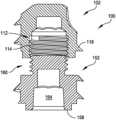
- a systemin some embodiments, includes a first component and a second component.
- the first componentincludes a first body having a first length extending from a first end to a second end. The first end is a leading end, and the second end includes a first coupling element.
- the second componentincludes a second body having a second length extending from a third end to a fourth end.
- the third endincludes a second coupling element, and the fourth end including a third coupling element.
- At least one of the first body and the second bodyincludes a first external fixation element configured to engage bone.
- the second coupling elementis configured to be coupled to the first coupling element to couple the first and second components together.
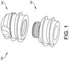
- FIG. 2is a side view of a first component of the multi-component implant having external fixation illustrated in FIG. 1 in accordance with some embodiments;
- FIG. 3is a top side view of the first component illustrated in FIG. 2 in accordance with some embodiments;
- FIG. 4is a cross-sectional view of the first component illustrated in FIG. 2 in accordance with some embodiments
- FIG. 5is a side view of a second component of the multi-component implant having external fixation illustrated in FIG. 1 in accordance with some embodiments;
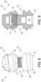
- FIG. 8is a side view of the first and second components being coupled together in accordance with some embodiments.
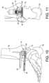
- FIG. 10illustrates one example of a multi-component prosthesis being implanted via an anterior approach in accordance with some embodiments
- FIG. 11is a cross-sectional view of a multi-component prosthesis being implanted via an anterior approach in accordance with some embodiments;
- FIG. 12illustrates one example of a multi-component prosthesis being implanted via a plantar approach in accordance with some embodiments
- component 102is inserted into the anterior opening 70 (e.g., resected joint spaced) formed between the tibia TB and talus TS.
- the insertion of component 102may be facilitated by engagement element 116 and coupling element 112 being engaged by tools 50 , 80 , as shown in FIGS. 12 and 13 .
- driving tool 80may be received within coupling element 112 of component 102 and then used to advance component 112 into the intramedullary channel 90 formed in tibia TB.
- Engagement element 116may then be engaged by tool 50 and tool 80 may be disengaged from coupling element 112 .
- the first pitchis equal to the second pitch, and wherein the first height is equal to the second height.
- the first pitchis equal to the second pitch, and the first height is different from the second height.
- the first heightvaries along a length of the first component, and the second height varies along a length of the second component.
- the first height and the second heightvary at an equal rate.
- the first fixation elementincludes a thread
- the second external fixation elementincludes a plurality of ridges
- the boneis a tibia
- the first component and the second componentare inserted through an anterior opening formed in the tibia.
- the third componentincludes a tibial tray.
- the third componentincludes another component of a tibial stem.
- the first component and second componentare coupled together ex situ.
- a methodincludes inserting a first component into a channel formed in a first bone such that a first external fixation element extending from a body of the first component engages bone, and coupling a second component to the first component in situ by engaging a first coupling element provided by the first component with a second coupling element provided by the second component.
- the second componentincludes a second external fixation element extending from a body of the second component.
- the third componentincludes a tibial tray.
- the third componentincludes another component of a tibial stem.
Landscapes
- Health & Medical Sciences (AREA)
- Orthopedic Medicine & Surgery (AREA)
- Life Sciences & Earth Sciences (AREA)
- Animal Behavior & Ethology (AREA)
- General Health & Medical Sciences (AREA)
- Engineering & Computer Science (AREA)
- Biomedical Technology (AREA)
- Heart & Thoracic Surgery (AREA)
- Veterinary Medicine (AREA)
- Public Health (AREA)
- Surgery (AREA)
- Cardiology (AREA)
- Oral & Maxillofacial Surgery (AREA)
- Vascular Medicine (AREA)
- Transplantation (AREA)
- Neurology (AREA)
- Nuclear Medicine, Radiotherapy & Molecular Imaging (AREA)
- Medical Informatics (AREA)
- Molecular Biology (AREA)
- Prostheses (AREA)
Abstract
Description
Claims (30)
Priority Applications (3)
| Application Number | Priority Date | Filing Date | Title |
|---|---|---|---|
| US17/660,489US12350160B2 (en) | 2021-06-08 | 2022-04-25 | Modular implant with external fixation |
| EP22170278.0AEP4101421A1 (en) | 2021-06-08 | 2022-04-27 | Modular implant with external fixation |
| US19/234,461US20250302630A1 (en) | 2021-06-08 | 2025-06-11 | Modular implant with external fixation |
Applications Claiming Priority (2)
| Application Number | Priority Date | Filing Date | Title |
|---|---|---|---|
| US202163208069P | 2021-06-08 | 2021-06-08 | |
| US17/660,489US12350160B2 (en) | 2021-06-08 | 2022-04-25 | Modular implant with external fixation |
Related Child Applications (1)
| Application Number | Title | Priority Date | Filing Date |
|---|---|---|---|
| US19/234,461DivisionUS20250302630A1 (en) | 2021-06-08 | 2025-06-11 | Modular implant with external fixation |
Publications (2)
| Publication Number | Publication Date |
|---|---|
| US20220387177A1 US20220387177A1 (en) | 2022-12-08 |
| US12350160B2true US12350160B2 (en) | 2025-07-08 |
Family
ID=81389046
Family Applications (2)
| Application Number | Title | Priority Date | Filing Date |
|---|---|---|---|
| US17/660,489Active2042-08-24US12350160B2 (en) | 2021-06-08 | 2022-04-25 | Modular implant with external fixation |
| US19/234,461PendingUS20250302630A1 (en) | 2021-06-08 | 2025-06-11 | Modular implant with external fixation |
Family Applications After (1)
| Application Number | Title | Priority Date | Filing Date |
|---|---|---|---|
| US19/234,461PendingUS20250302630A1 (en) | 2021-06-08 | 2025-06-11 | Modular implant with external fixation |
Country Status (2)
| Country | Link |
|---|---|
| US (2) | US12350160B2 (en) |
| EP (1) | EP4101421A1 (en) |
Citations (207)
| Publication number | Priority date | Publication date | Assignee | Title |
|---|---|---|---|---|
| US3839742A (en) | 1972-07-22 | 1974-10-08 | Link W | Prosthetic device for the tarsal joint |
| US3872519A (en) | 1974-04-04 | 1975-03-25 | Nicholas J Giannestras | Total ankle prosthesis |
| US3886599A (en) | 1974-07-25 | 1975-06-03 | Schlein Louis Charles | Surgically implantable total ankle prosthesis |
| US3889300A (en) | 1974-08-28 | 1975-06-17 | Wright Mfg | Articulated two-part prosthesis replacing the ankle joint |
| US3896502A (en) | 1973-01-12 | 1975-07-29 | Nat Res Dev | Endoprosthetic bone joint devices |
| US3896503A (en) | 1973-02-09 | 1975-07-29 | Nat Res Dev | Endosphosthetic ankle joint devices |
| US3975778A (en) | 1975-07-14 | 1976-08-24 | Newton Iii St Elmo | Total ankle arthroplasty |
| US3987500A (en) | 1976-01-28 | 1976-10-26 | Schlein Allen P | Surgically implantable total ankle prosthesis |
| US4021864A (en) | 1976-04-14 | 1977-05-10 | The Regents Of The University Of California | Ankle prosthesis |
| US4069518A (en) | 1976-08-31 | 1978-01-24 | Groth Jr Harry E | Total ankle prosthesis |
| US4156944A (en) | 1976-11-15 | 1979-06-05 | Sulzer Brothers Limited | Total ankle prosthesis |
| US4166292A (en) | 1977-09-08 | 1979-09-04 | Carbomedics, Inc. | Stress reinforced artificial joint prostheses |
| US4204284A (en) | 1977-11-16 | 1980-05-27 | Lord Corporation | Joint prosthesis with contoured pin |
| US4232404A (en) | 1977-07-18 | 1980-11-11 | National Research Development Corporation | Endoprosthetic ankle joint |
| US4309778A (en) | 1979-07-02 | 1982-01-12 | Biomedical Engineering Corp. | New Jersey meniscal bearing knee replacement |
| US4470158A (en) | 1978-03-10 | 1984-09-11 | Biomedical Engineering Corp. | Joint endoprosthesis |
| US4755185A (en) | 1987-01-27 | 1988-07-05 | Boehringer Mannheim Corporation | Prosthetic joint |
| US4968316A (en) | 1988-12-12 | 1990-11-06 | Hergenroeder Patrick T | Arthroscopic ankle joint distraction method |
| US5041139A (en) | 1989-04-25 | 1991-08-20 | Branemark Per Ingvar | Anchoring element for supporting a joint mechanism of an ankle, hip or other reconstructed joint |
| US5312412A (en) | 1993-02-03 | 1994-05-17 | Whipple Terry L | Fixation alignment guide for surgical use |
| US5326365A (en) | 1992-04-10 | 1994-07-05 | Alvine Franklin G | Ankle implant |
| US5354300A (en) | 1993-01-15 | 1994-10-11 | Depuy Inc. | Drill guide apparatus for installing a transverse pin |
| US5423825A (en) | 1992-06-10 | 1995-06-13 | Levine; Andrew S. | Spinal fusion instruments and methods |
| US5476466A (en) | 1993-07-20 | 1995-12-19 | Zimmer, Inc. | Orthopaedic positioning instrument |
| WO1996025106A1 (en) | 1995-02-15 | 1996-08-22 | Smith & Nephew Richards Inc. | Tibial resection instrument |
| US5601563A (en) | 1995-08-25 | 1997-02-11 | Zimmer, Inc. | Orthopaedic milling template with attachable cutting guide |
| US5634927A (en) | 1995-07-06 | 1997-06-03 | Zimmer, Inc. | Sizing plate and drill guide assembly for orthopaedic knee instrumentation |
| US5674223A (en) | 1994-02-16 | 1997-10-07 | Joint Medical Products Corporation | Instrument for implanting a femoral knee prosthesis |
| US5735904A (en) | 1995-07-05 | 1998-04-07 | Pappas; Michael J. | Spacer for establishng prosthetic gap and ligamentous tension |
| US5766259A (en) | 1995-03-14 | 1998-06-16 | Sammarco; Giacomo J. | Total ankle prosthesis and method |
| US5776200A (en) | 1995-02-15 | 1998-07-07 | Smith & Nephew, Inc. | Tibial trial prosthesis and bone preparation system |
| US5817097A (en) | 1995-08-03 | 1998-10-06 | Synvasive Technology, Inc. | Bone saw blade guide with magnet |
| US5824106A (en) | 1996-04-11 | 1998-10-20 | Tornier Sa | Ankle prosthesis |
| US5879389A (en) | 1995-04-07 | 1999-03-09 | Koshino; Tomihisa | Medical substituting element for hard tissues and artificial joint |
| US5885299A (en) | 1994-09-15 | 1999-03-23 | Surgical Dynamics, Inc. | Apparatus and method for implant insertion |
| US5888203A (en) | 1995-03-09 | 1999-03-30 | Goldberg; Robert | Biaxial ligamentous-restrained prostheses for upper and lower extremity arthroplasties |
| US5897559A (en) | 1995-11-02 | 1999-04-27 | Medidea, Llc | Bone cutting guides for use in the implantation of prosthetic joint components |
| US5935132A (en) | 1997-12-10 | 1999-08-10 | Johnson & Johnson Professional, Inc. | Surgical guide and cutting system |
| US6002859A (en) | 1997-02-21 | 1999-12-14 | Carnegie Mellon University | Apparatus and method facilitating the implantation of artificial components in joints |
| US6033405A (en) | 1994-09-15 | 2000-03-07 | Surgical Dynamics, Inc. | Apparatus and method for implant insertion |
| US6183519B1 (en) | 1997-03-10 | 2001-02-06 | Tornier Sa | Ankle prosthesis |
| US6245109B1 (en) | 1999-11-18 | 2001-06-12 | Intellijoint Systems, Ltd. | Artificial joint system and method utilizing same for monitoring wear and displacement of artificial joint members |
| WO2001066021A1 (en) | 2000-03-10 | 2001-09-13 | Smith & Nephew, Inc | A method of arthroplasty on a knee joint and apparatus for use in same |
| US6342056B1 (en) | 2000-02-04 | 2002-01-29 | Jean-Marc Mac-Thiong | Surgical drill guide and method for using the same |
| US6344043B1 (en) | 1997-11-18 | 2002-02-05 | Michael J. Pappas | Anterior-posterior femoral resection guide with set of detachable collets |
| US20020068977A1 (en) | 2000-12-05 | 2002-06-06 | Jackson Roger P. | Anterior variable expandable fusion cage |
| US6409767B1 (en) | 1999-11-05 | 2002-06-25 | European Foot Platform | Ankle prosthesis |
| US20020082607A1 (en) | 2000-12-27 | 2002-06-27 | Heldreth Mark A. | Prosthesis evaluation assembly and associated method |
| US6413260B1 (en)* | 1999-08-17 | 2002-07-02 | Pioneer Laboratories, Inc. | Bone connector system |
| US6436146B1 (en) | 1997-12-10 | 2002-08-20 | Bioprofile | Implant for treating ailments of a joint or a bone |
| US20020133164A1 (en) | 2000-06-29 | 2002-09-19 | Williamson Richard V. | Instruments and methods for use in performing knee surgery |
| US6478800B1 (en) | 2000-05-08 | 2002-11-12 | Depuy Acromed, Inc. | Medical installation tool |
| US20020173853A1 (en) | 2001-05-17 | 2002-11-21 | Corl Harry E. | Movable joint and method for coating movable joints |
| US6520964B2 (en) | 2000-05-01 | 2003-02-18 | Std Manufacturing, Inc. | System and method for joint resurface repair |
| US6530930B1 (en) | 1998-06-09 | 2003-03-11 | Nu Vasive, Inc. | Spinal surgery guidance platform |
| US20030078669A1 (en) | 1993-11-01 | 2003-04-24 | Martin Daniel L. | Compliant tibial tray assembly |
| DE10156311A1 (en)* | 2001-11-19 | 2003-06-05 | Petra Thomaschewski | Bone screw fixer of threaded core comprises externally threaded screw-in dowel with co-axial center cavity for screw and flanged at rear end flush with corticalis. |
| US6610095B1 (en) | 2000-01-30 | 2003-08-26 | Diamicron, Inc. | Prosthetic joint having substrate surface topographical featurers and at least one diamond articulation surface |
| US6610067B2 (en) | 2000-05-01 | 2003-08-26 | Arthrosurface, Incorporated | System and method for joint resurface repair |
| US6620168B1 (en) | 1998-10-13 | 2003-09-16 | Stryker Technologies Corporation | Methods and tools for tibial intermedullary revision surgery and associated tibial components |
| US20030208280A1 (en) | 2000-04-21 | 2003-11-06 | Behrooz Tohidi | Wear resistant artificial joint |
| US6645215B1 (en) | 2002-08-07 | 2003-11-11 | Howmedica Osteonics Corp. | Tibial rotation guide |
| US6663669B1 (en) | 1999-10-22 | 2003-12-16 | Mark A Reiley | Ankle replacement system |
| US20030236522A1 (en) | 2002-06-21 | 2003-12-25 | Jack Long | Prosthesis cavity cutting guide, cutting tool and method |
| US6673116B2 (en) | 1999-10-22 | 2004-01-06 | Mark A. Reiley | Intramedullary guidance systems and methods for installing ankle replacement prostheses |
| US6679917B2 (en) | 2000-05-01 | 2004-01-20 | Arthrosurface, Incorporated | System and method for joint resurface repair |
| US20040030399A1 (en) | 2000-05-22 | 2004-02-12 | Joseph-Guy Asencio | Articulation prosthesis |
| US20040039394A1 (en) | 2002-08-26 | 2004-02-26 | Conti Stephen F. | Ankle fusion guide and method |
| US20040068322A1 (en) | 2002-10-04 | 2004-04-08 | Ferree Bret A. | Reduced-friction artificial joints and components therefor |
| US6719799B1 (en) | 1998-09-11 | 2004-04-13 | Argomedical Ag | Implantable prosthesis having at least two sections which can be displaced in relation to one another, and the use of displaceable sections |
| US20040167631A1 (en) | 2003-02-21 | 2004-08-26 | Kenny Luchesi | Fixation surface for ankle prosthesis |
| US20040186585A1 (en) | 2003-03-21 | 2004-09-23 | Lawrence Feiwell | Sphere-on-sphere ankle prosthesis |
| US20040216259A1 (en) | 1998-10-09 | 2004-11-04 | Valeo Electrical Systems, Inc. | Window wiper arm drive and window lock system |
| US20040236431A1 (en) | 2001-06-28 | 2004-11-25 | Ronald Sekel | Universal prosthesis |
| US6824567B2 (en) | 1999-08-03 | 2004-11-30 | Tornier | Method of positioning a malleolar implant for partial or total ankle prosthesis |
| US20050004676A1 (en) | 2002-06-27 | 2005-01-06 | Schon Lew C. | Semi-constrained ankle joint prosthesis and its method of implantation |
| US6852130B2 (en) | 2002-03-08 | 2005-02-08 | Waldemar Link Gmbh & Co. Kg | Ankle-joint endoprosthesis |
| WO2005011523A2 (en) | 2003-08-01 | 2005-02-10 | Spinal Kinetics, Inc. | Prosthetic intervertebral disc and methods for using same |
| US6863691B2 (en) | 2002-04-29 | 2005-03-08 | Timothy J. Short | Ankle implant |
| US6875222B2 (en) | 2002-03-12 | 2005-04-05 | Depuy Products, Inc. | Blade for resection of bone for prosthesis implantation, blade stop and method |
| US20050165408A1 (en) | 2004-01-26 | 2005-07-28 | Puno Rolando M. | Methods and instrumentation for inserting intervertebral grafts and devices |
| US6926739B1 (en) | 1999-05-13 | 2005-08-09 | John J. O'Connor | Prosthesis device for human articulations, in particular for the ankle articulation |
| US20050192674A1 (en) | 1999-10-08 | 2005-09-01 | Ferree Bret A. | Prosthetic joints with contained compressible resilient members |
| US6939380B2 (en) | 2002-12-23 | 2005-09-06 | Depuy Products, Inc. | Mobile talar component for total ankle replacement implant |
| US20060009857A1 (en) | 2004-07-08 | 2006-01-12 | Gibbs Phillip M | Method and apparatus for surface hardening implants |
| US20060036257A1 (en) | 2004-08-06 | 2006-02-16 | Zimmer Technology, Inc. | Tibial spacer blocks and femoral cutting guide |
| US7001394B2 (en) | 2000-12-28 | 2006-02-21 | Depuy Products, Inc. | Method and apparatus for surgically preparing a tibia for implantation of a prosthetic implant component which has an offset stem |
| WO2006023824A2 (en) | 2004-08-19 | 2006-03-02 | Kinetikos Medical Incorporated | Ankle prosthesis and method of curved resection |
| WO2006022923A1 (en) | 2004-05-07 | 2006-03-02 | Ibalance Medical, Inc. | Open wedge osteotomy system and surgical method |
| US7011687B2 (en) | 2003-01-06 | 2006-03-14 | Depuy Products, Inc. | Ankle prosthesis with a front loading bearing and associated method |
| US20060116679A1 (en) | 2004-11-30 | 2006-06-01 | Stryker Trauma Sa | Bone plating implants, instruments and methods |
| WO2006099270A2 (en) | 2005-03-14 | 2006-09-21 | Topez Orthopedics, Inc. | Ankle replacement system |
| US20060235541A1 (en) | 2005-04-15 | 2006-10-19 | Zimmer Technology, Inc. | Bearing implant |
| US20060247788A1 (en) | 2005-03-31 | 2006-11-02 | The Regents Of The University Of California | Total ankle arthroplasty |
| US7163541B2 (en) | 2002-12-03 | 2007-01-16 | Arthrosurface Incorporated | Tibial resurfacing system |
| US20070038303A1 (en) | 2006-08-15 | 2007-02-15 | Ebi, L.P. | Foot/ankle implant and associated method |
| US20070100346A1 (en) | 2005-10-27 | 2007-05-03 | Wyss Joseph G | Support for locating instrument guides |
| US20070112431A1 (en) | 2003-08-27 | 2007-05-17 | Hakon Kofoed | Ankle-joint endoprosthesis |
| US7238190B2 (en) | 2003-03-28 | 2007-07-03 | Concepts In Medicine Iii, Llc | Surgical apparatus to allow replacement of degenerative ankle tissue |
| US20070173947A1 (en) | 2006-01-24 | 2007-07-26 | Tornier | surgical instrumentation kit for inserting an ankle prosthesis |
| US20070173944A1 (en) | 2005-12-12 | 2007-07-26 | Waldemar Link Gmbh & Co. Kg | Endoprosthesis with intermediate part |
| WO2007084846A2 (en) | 2006-01-20 | 2007-07-26 | Hasselman Carl T | Method of preparing an ankle joint for replacement, joint prosthesis, and cutting alignment apparatus for use in performing an arthroplasty procedure |
| US7252684B2 (en) | 2002-11-06 | 2007-08-07 | Southwest Research Institute | Ceramic in replacement components |
| US20070213830A1 (en) | 2005-01-31 | 2007-09-13 | Ammann Kelly G | Method and apparatus for performing an open wedge, high tibial osteotomy |
| US20070233129A1 (en) | 2006-02-17 | 2007-10-04 | Rudolf Bertagnoli | Method and system for performing interspinous space preparation for receiving an implant |
| US20070276400A1 (en) | 2003-09-22 | 2007-11-29 | Gary Moore | Drill Guide Assembly |
| US20070288030A1 (en) | 2006-06-09 | 2007-12-13 | Biomet Manufacturing Corp. | Patient Specific Knee Alignment Guide And Associated Method |
| US20080015602A1 (en) | 2006-06-22 | 2008-01-17 | Howmedica Osteonics Corp. | Cutting block for bone resection |
| US7323012B1 (en) | 2004-03-17 | 2008-01-29 | Biomet Manufacturing Corp. | Ankle implant |
| US20080097617A1 (en) | 2004-11-08 | 2008-04-24 | Alphamed Medizintechnik Fischer Gmbh | Ankle Joint Endoprosthesis Elements |
| US20080103603A1 (en) | 2006-10-26 | 2008-05-01 | Beat Hintermann | Ankle prosthesis with neutral position adjustment |
| US20080109081A1 (en) | 2003-10-22 | 2008-05-08 | Qi-Bin Bao | Joint Arthroplasty Devices Having Articulating Members |
| US20080195233A1 (en) | 2006-10-13 | 2008-08-14 | Irene Ferrari | Ankle prosthesis for the arthrodesis of the calcaneum |
| US20080215156A1 (en) | 2004-06-30 | 2008-09-04 | Synergy Disc Replacement | Joint Prostheses |
| US20080287954A1 (en) | 2007-05-14 | 2008-11-20 | Queen's University At Kingston | Patient-specific surgical guidance tool and method of use |
| US20080312745A1 (en) | 2007-06-12 | 2008-12-18 | Waldemar Link Gmbh & Co. Kg | Endoprosthesis with convex configuration |
| US20090018660A1 (en)* | 2007-07-13 | 2009-01-15 | Roush Thomas F | Hybrid fusion/arthroplasty device |
| US20090024131A1 (en) | 2006-02-27 | 2009-01-22 | Biomet Manufacturing Corp. | Patient specific guides |
| US7481814B1 (en) | 2003-07-28 | 2009-01-27 | Biomet Manufacturing Corporation | Method and apparatus for use of a mill or reamer |
| US7485147B2 (en) | 2004-02-13 | 2009-02-03 | Pappas Michael J | Ankle prosthesis including tibial component having peripheral wall for preventing the formation of bone cysts |
| US20090043310A1 (en) | 2005-02-08 | 2009-02-12 | Rasmussen G Lynn | Arthroplasty systems and methods for optimally aligning and tensioning a knee prosthesis |
| US20090054992A1 (en) | 2004-06-23 | 2009-02-26 | Landes Mark D | Modular Ankle Prosthesis and Associated Method |
| US20090082875A1 (en) | 2007-09-26 | 2009-03-26 | Depuy Products, Inc. | Talar implant system and method |
| US20090105767A1 (en) | 2007-10-18 | 2009-04-23 | Inbone Technologies, Inc. | Total joint subsidence protector |
| US20090105840A1 (en) | 2007-10-18 | 2009-04-23 | Inbone Technologies, Inc. | Fibular stiffener and bony defect replacer |
| US7534270B2 (en) | 2003-09-03 | 2009-05-19 | Integra Lifesciences Corporation | Modular total ankle prosthesis apparatuses and methods |
| US20090198341A1 (en) | 2006-03-02 | 2009-08-06 | Talus Medical, Inc. | Bone prosthesis |
| US20090234360A1 (en) | 2006-12-12 | 2009-09-17 | Vladimir Alexander | Laser assisted total joint arthroplasty |
| US20090276052A1 (en) | 2008-04-30 | 2009-11-05 | Exploramed Nc4, Inc. | Ball and socket assembly |
| US7615082B2 (en) | 2002-03-22 | 2009-11-10 | Hjs Gelenk System Gmbh | Artificial joint |
| US7618421B2 (en) | 2001-10-10 | 2009-11-17 | Howmedica Osteonics Corp. | Tools for femoral resection in knee surgery |
| US7625409B2 (en) | 2003-10-14 | 2009-12-01 | University Of Iowa Research Foundation | Ankle prosthesis |
| WO2009158522A1 (en) | 2008-06-25 | 2009-12-30 | Small Bone Innovations, Inc. | Surgical instrumentation and methods of use for implanting a prothesis |
| US20100010493A1 (en) | 2006-04-05 | 2010-01-14 | Depuy International Limited | Orthopaedic cutting guide instrument |
| US20100023126A1 (en) | 2008-07-24 | 2010-01-28 | Grotz R Thomas | Resilient arthroplasty device |
| US20100057216A1 (en) | 2008-07-23 | 2010-03-04 | Jamy Gannoe | System and method for joint resurfacing with dynamic fixation |
| US7678151B2 (en) | 2000-05-01 | 2010-03-16 | Ek Steven W | System and method for joint resurface repair |
| US20100069910A1 (en) | 2006-12-15 | 2010-03-18 | Synthes Usa, Llc | Osteotomy Guide and Method of Cutting the Medial Distal Tibia Employing the Same |
| US7713305B2 (en) | 2000-05-01 | 2010-05-11 | Arthrosurface, Inc. | Articular surface implant |
| US7763080B2 (en) | 2004-04-30 | 2010-07-27 | Depuy Products, Inc. | Implant system with migration measurement capacity |
| WO2010099142A1 (en) | 2009-02-24 | 2010-09-02 | Wright Medical Technology, Inc. | Patient specific surgical guide locator and mount |
| US20100241237A1 (en) | 2008-09-22 | 2010-09-23 | Buechel-Pappas Trust | Fixed bearing joint endoprosthesis with combined congruent - incongruent prosthetic articulations |
| US7803158B2 (en) | 2004-03-26 | 2010-09-28 | Depuy Products, Inc. | Navigated pin placement for orthopaedic procedures |
| US7850698B2 (en) | 2005-02-17 | 2010-12-14 | Zimmer Technology, Inc. | Tibial trialing assembly and method of trialing a tibial implant |
| US20100318088A1 (en) | 2007-07-20 | 2010-12-16 | Talus Medical, Inc. | Methods and devices for deploying biological implants |
| US20100331984A1 (en) | 2009-06-26 | 2010-12-30 | The Cleveland Clinic Foundation | Prosthetic joint component with rotation-regulating structure |
| US20110029090A1 (en) | 2007-09-25 | 2011-02-03 | Depuy Products, Inc. | Prosthesis with modular extensions |
| WO2011015863A1 (en) | 2009-08-06 | 2011-02-10 | Depuy (Ireland) | Surgical instrument and system of surgical instruments |
| US20110035019A1 (en) | 2009-07-09 | 2011-02-10 | Wright State University | Total ankle replacement system |
| US20110035018A1 (en) | 2007-09-25 | 2011-02-10 | Depuy Products, Inc. | Prosthesis with composite component |
| US7896883B2 (en) | 2000-05-01 | 2011-03-01 | Arthrosurface, Inc. | Bone resurfacing system and method |
| US7896885B2 (en) | 2002-12-03 | 2011-03-01 | Arthrosurface Inc. | Retrograde delivery of resurfacing devices |
| US7909882B2 (en) | 2007-01-19 | 2011-03-22 | Albert Stinnette | Socket and prosthesis for joint replacement |
| US20110106268A1 (en) | 2009-10-30 | 2011-05-05 | Depuy Products, Inc. | Prosthesis for cemented fixation and method for making the prosthesis |
| WO2011063281A1 (en) | 2009-11-20 | 2011-05-26 | Knee Creations, Llc | Navigation and positioning instruments for joint repair |
| US20110125284A1 (en) | 2008-05-28 | 2011-05-26 | University Of Bath | Improvements in or Relating to Joints and/or Implants |
| US20110125275A1 (en) | 2009-11-16 | 2011-05-26 | New York Society For The Ruptured And Crippled Maintaining The Hospital For Special Surgery | Prosthetic condylar joints with articulating bearing surfaces having a translating contact point during rotation thereof |
| US20110152868A1 (en) | 2009-12-18 | 2011-06-23 | Lampros Kourtis | Method, device, and system for shaving and shaping of a joint |
| US20110166608A1 (en) | 2009-07-14 | 2011-07-07 | Neil Duggal | Joint Arthrodesis and Arthroplasty |
| US8012217B2 (en) | 2008-07-03 | 2011-09-06 | Fellowship of Orthopaedic Researchers, LLC | Talar implants and methods of use |
| US20110218542A1 (en) | 2009-04-13 | 2011-09-08 | Lian George J | Systems and instrumentalities for use in total ankle replacement surgery |
| US20110295380A1 (en) | 2010-05-28 | 2011-12-01 | Long Jack F | Semi-constrained ankle prosthesis having a rotating bearing insert |
| GB2480846A (en) | 2010-06-03 | 2011-12-07 | Biomet Uk Ltd | Tool with adjustable guide surface. |
| US20120010718A1 (en) | 2010-07-08 | 2012-01-12 | Still Gregory P | Partial ankle joint replacement implant |
| US20120046753A1 (en) | 2010-08-23 | 2012-02-23 | Fellowship of Orthopaedic Researchs, Inc. | Talar implants and methods of use |
| US20120053644A1 (en) | 2010-08-26 | 2012-03-01 | Moximed, Inc. | Implantable Device For Relieving Ankle Pain |
| US20120083789A1 (en) | 2010-10-01 | 2012-04-05 | Vot, Llc | Method of implanting a prosthesis device using bone cement in liquid form |
| US20120109131A1 (en) | 2009-06-30 | 2012-05-03 | Universitat Rostock | Device for in situ milling of joint surfaces |
| US20120109326A1 (en) | 2010-11-02 | 2012-05-03 | Perler Adam D | Prosthetic Device with Multi-Axis Dual Bearing Assembly and Methods for Resection |
| US8172850B2 (en) | 2007-04-26 | 2012-05-08 | Mcminn Derek James Wallace | Alignment device |
| US8177841B2 (en) | 2000-05-01 | 2012-05-15 | Arthrosurface Inc. | System and method for joint resurface repair |
| US20120136443A1 (en) | 2009-03-04 | 2012-05-31 | Advanced Medical Technologies Ag | Implant system having at least three support elements |
| WO2012088036A1 (en) | 2010-12-20 | 2012-06-28 | Wright Medical Technology, Inc. | Orthopedic surgical guide |
| US20120185057A1 (en) | 2010-07-07 | 2012-07-19 | Global Orthopaedics Llc | Malleolar replacement devices |
| WO2012116089A1 (en) | 2011-02-22 | 2012-08-30 | Knee Creations, Llc | Navigation and positioning systems and guide instruments for joint repair |
| US8268007B2 (en) | 2009-06-26 | 2012-09-18 | The Cleveland Clinic Foundation | Multi-piece prosthetic joint component |
| US20120239045A1 (en) | 2011-03-17 | 2012-09-20 | Zimmer, Inc. | Patient-specific instruments for total ankle arthroplasty |
| US20120245701A1 (en) | 2011-03-24 | 2012-09-27 | Rudolf Zak | Hemi Ankle Implant |
| US20120271430A1 (en) | 2011-04-22 | 2012-10-25 | Medicinelodge, Inc. Dba Imds Co-Innovation | Ankle arthroplasty |
| US20120277745A1 (en) | 2009-04-21 | 2012-11-01 | Emmanuel Lizee | Systems and methods for positioning a foot in ankle arthrodesis |
| US8303667B2 (en) | 2010-03-02 | 2012-11-06 | Alastair Younger | Fastening system for prostheses |
| US8313492B2 (en) | 2008-05-30 | 2012-11-20 | Wright Medical Technology, Inc. | Drill guide assembly |
| US8323346B2 (en) | 2006-11-17 | 2012-12-04 | Scyon Orthopaedics Ag | Wear-reducing geometry of articulations in total joint replacements |
| US8337503B2 (en) | 2009-04-13 | 2012-12-25 | George John Lian | Custom radiographically designed cutting guides and instruments for use in total ankle replacement surgery |
| US8361159B2 (en) | 2002-12-03 | 2013-01-29 | Arthrosurface, Inc. | System for articular surface replacement |
| US20130041473A1 (en) | 2010-02-19 | 2013-02-14 | Newdeal | Ankle prosthesis with simplified adjustment |
| US20130116797A1 (en) | 2011-11-04 | 2013-05-09 | Tornier Sas | Surgical instrumentation assembly for positioning an ankle prosthesis |
| US20130131822A1 (en)* | 2011-11-17 | 2013-05-23 | Orthohelix Surgical Designs, Inc. | Hammertoe implant |
| US20130274814A1 (en)* | 2009-02-19 | 2013-10-17 | Nextremity Solutions, Llc | Bone joining apparatus and method |
| US20130338722A1 (en)* | 2010-07-07 | 2013-12-19 | Matthew Adam Yalizis | Compression bone screw |
| CA2836651A1 (en) | 2012-12-27 | 2014-06-27 | Wright Medical Technology, Inc. | Ankle replacement system and method |
| WO2014152308A1 (en) | 2013-03-14 | 2014-09-25 | Wright Medical Technology, Inc. | Intramedullary ankle technique and system |
| US8911444B2 (en) | 2010-11-02 | 2014-12-16 | Zimmer, Inc. | Composite surgical instrument |
| EP2967697A1 (en) | 2013-03-14 | 2016-01-20 | Wright Medical Technology, Inc. | Ankle replacement system and method |
| US9282977B2 (en)* | 2013-10-23 | 2016-03-15 | Extremity Medical Llc | Methods for bone fixation using an intramedullary fixation implant |
| US9610109B2 (en)* | 2011-08-16 | 2017-04-04 | Howmedica Osteonics Corp. | Wedge shaped fracture fixation devices and methods for using the same |
| WO2017105815A1 (en) | 2015-12-16 | 2017-06-22 | Tornier, Inc. | Patient specific instruments and methods for joint prosthesis |
| US20180055648A1 (en)* | 2016-08-30 | 2018-03-01 | Wright Medical Technology, Inc. | Revision total ankle implants |
| US9907561B2 (en) | 2012-12-27 | 2018-03-06 | Wright Medical Technologies, Inc. | Ankle replacement system and method |
| US10034678B2 (en) | 2002-05-15 | 2018-07-31 | Howmedica Osteonics Corporation | Tibial arthroplasty jig |
| US20180360512A1 (en)* | 2011-07-15 | 2018-12-20 | Globus Medical, Inc. | Screw implants for bone fusion |
| US10206688B2 (en) | 2006-02-15 | 2019-02-19 | Howmedica Osteonics Corporation | Arthroplasty devices and related methods |
| WO2019060780A2 (en) | 2017-09-25 | 2019-03-28 | Tornier, Inc. | Patient specific stemless prosthesis anchor components |
| US20200038189A1 (en)* | 2018-03-01 | 2020-02-06 | Paragon 28, Inc. | Implants, systems, and methods of use and assembly |
| US20200214828A1 (en)* | 2019-01-09 | 2020-07-09 | Roberto Ivan Diaz | Bone Anchor and Related Devices, Systems, and Methods |
| US20200237415A1 (en)* | 2017-09-05 | 2020-07-30 | ExsoMed Corporation | Intramedullary threaded nail for radial cortical fixation |
| US20210338294A1 (en)* | 2017-12-06 | 2021-11-04 | Stryker European Operations Holdings Llc | Orthopedic Locking Screw |
- 2022
- 2022-04-25USUS17/660,489patent/US12350160B2/enactiveActive
- 2022-04-27EPEP22170278.0Apatent/EP4101421A1/enactivePending
- 2025
- 2025-06-11USUS19/234,461patent/US20250302630A1/enactivePending
Patent Citations (260)
| Publication number | Priority date | Publication date | Assignee | Title |
|---|---|---|---|---|
| US3839742A (en) | 1972-07-22 | 1974-10-08 | Link W | Prosthetic device for the tarsal joint |
| US3896502A (en) | 1973-01-12 | 1975-07-29 | Nat Res Dev | Endoprosthetic bone joint devices |
| US3896503A (en) | 1973-02-09 | 1975-07-29 | Nat Res Dev | Endosphosthetic ankle joint devices |
| US3872519A (en) | 1974-04-04 | 1975-03-25 | Nicholas J Giannestras | Total ankle prosthesis |
| US3886599A (en) | 1974-07-25 | 1975-06-03 | Schlein Louis Charles | Surgically implantable total ankle prosthesis |
| US3889300A (en) | 1974-08-28 | 1975-06-17 | Wright Mfg | Articulated two-part prosthesis replacing the ankle joint |
| US3975778A (en) | 1975-07-14 | 1976-08-24 | Newton Iii St Elmo | Total ankle arthroplasty |
| US3987500A (en) | 1976-01-28 | 1976-10-26 | Schlein Allen P | Surgically implantable total ankle prosthesis |
| US4021864A (en) | 1976-04-14 | 1977-05-10 | The Regents Of The University Of California | Ankle prosthesis |
| US4069518A (en) | 1976-08-31 | 1978-01-24 | Groth Jr Harry E | Total ankle prosthesis |
| US4156944A (en) | 1976-11-15 | 1979-06-05 | Sulzer Brothers Limited | Total ankle prosthesis |
| US4232404A (en) | 1977-07-18 | 1980-11-11 | National Research Development Corporation | Endoprosthetic ankle joint |
| US4166292A (en) | 1977-09-08 | 1979-09-04 | Carbomedics, Inc. | Stress reinforced artificial joint prostheses |
| US4204284A (en) | 1977-11-16 | 1980-05-27 | Lord Corporation | Joint prosthesis with contoured pin |
| US4470158A (en) | 1978-03-10 | 1984-09-11 | Biomedical Engineering Corp. | Joint endoprosthesis |
| US4309778A (en) | 1979-07-02 | 1982-01-12 | Biomedical Engineering Corp. | New Jersey meniscal bearing knee replacement |
| US4755185A (en) | 1987-01-27 | 1988-07-05 | Boehringer Mannheim Corporation | Prosthetic joint |
| US4968316A (en) | 1988-12-12 | 1990-11-06 | Hergenroeder Patrick T | Arthroscopic ankle joint distraction method |
| US5041139A (en) | 1989-04-25 | 1991-08-20 | Branemark Per Ingvar | Anchoring element for supporting a joint mechanism of an ankle, hip or other reconstructed joint |
| US5326365A (en) | 1992-04-10 | 1994-07-05 | Alvine Franklin G | Ankle implant |
| US5423825A (en) | 1992-06-10 | 1995-06-13 | Levine; Andrew S. | Spinal fusion instruments and methods |
| US5354300A (en) | 1993-01-15 | 1994-10-11 | Depuy Inc. | Drill guide apparatus for installing a transverse pin |
| US5312412A (en) | 1993-02-03 | 1994-05-17 | Whipple Terry L | Fixation alignment guide for surgical use |
| US5476466A (en) | 1993-07-20 | 1995-12-19 | Zimmer, Inc. | Orthopaedic positioning instrument |
| US20030078669A1 (en) | 1993-11-01 | 2003-04-24 | Martin Daniel L. | Compliant tibial tray assembly |
| US5674223A (en) | 1994-02-16 | 1997-10-07 | Joint Medical Products Corporation | Instrument for implanting a femoral knee prosthesis |
| US5885299A (en) | 1994-09-15 | 1999-03-23 | Surgical Dynamics, Inc. | Apparatus and method for implant insertion |
| US6033405A (en) | 1994-09-15 | 2000-03-07 | Surgical Dynamics, Inc. | Apparatus and method for implant insertion |
| WO1996025106A1 (en) | 1995-02-15 | 1996-08-22 | Smith & Nephew Richards Inc. | Tibial resection instrument |
| US5667511A (en) | 1995-02-15 | 1997-09-16 | Smith & Nephew Richards Inc. | Tibial resection instrumentation and surgical method |
| US5628749A (en) | 1995-02-15 | 1997-05-13 | Smith & Nephew Richards Inc. | Tibial resection instrumentation and surgical method |
| US5776200A (en) | 1995-02-15 | 1998-07-07 | Smith & Nephew, Inc. | Tibial trial prosthesis and bone preparation system |
| JPH11500035A (en) | 1995-02-15 | 1999-01-06 | スミス アンド ネフュー インコーポレーテッド | Tibial resection instrument |
| US5888203A (en) | 1995-03-09 | 1999-03-30 | Goldberg; Robert | Biaxial ligamentous-restrained prostheses for upper and lower extremity arthroplasties |
| US5766259A (en) | 1995-03-14 | 1998-06-16 | Sammarco; Giacomo J. | Total ankle prosthesis and method |
| US5879389A (en) | 1995-04-07 | 1999-03-09 | Koshino; Tomihisa | Medical substituting element for hard tissues and artificial joint |
| US6102952A (en) | 1995-04-07 | 2000-08-15 | Koshino; Tomihisa | Medical substituting element for hard tissues and artificial joint |
| US5735904A (en) | 1995-07-05 | 1998-04-07 | Pappas; Michael J. | Spacer for establishng prosthetic gap and ligamentous tension |
| US5634927A (en) | 1995-07-06 | 1997-06-03 | Zimmer, Inc. | Sizing plate and drill guide assembly for orthopaedic knee instrumentation |
| US5817097A (en) | 1995-08-03 | 1998-10-06 | Synvasive Technology, Inc. | Bone saw blade guide with magnet |
| US5601563A (en) | 1995-08-25 | 1997-02-11 | Zimmer, Inc. | Orthopaedic milling template with attachable cutting guide |
| US5897559A (en) | 1995-11-02 | 1999-04-27 | Medidea, Llc | Bone cutting guides for use in the implantation of prosthetic joint components |
| US5824106A (en) | 1996-04-11 | 1998-10-20 | Tornier Sa | Ankle prosthesis |
| US6002859A (en) | 1997-02-21 | 1999-12-14 | Carnegie Mellon University | Apparatus and method facilitating the implantation of artificial components in joints |
| US6183519B1 (en) | 1997-03-10 | 2001-02-06 | Tornier Sa | Ankle prosthesis |
| US6344043B1 (en) | 1997-11-18 | 2002-02-05 | Michael J. Pappas | Anterior-posterior femoral resection guide with set of detachable collets |
| US5935132A (en) | 1997-12-10 | 1999-08-10 | Johnson & Johnson Professional, Inc. | Surgical guide and cutting system |
| US6436146B1 (en) | 1997-12-10 | 2002-08-20 | Bioprofile | Implant for treating ailments of a joint or a bone |
| US6530930B1 (en) | 1998-06-09 | 2003-03-11 | Nu Vasive, Inc. | Spinal surgery guidance platform |
| US6719799B1 (en) | 1998-09-11 | 2004-04-13 | Argomedical Ag | Implantable prosthesis having at least two sections which can be displaced in relation to one another, and the use of displaceable sections |
| US20040216259A1 (en) | 1998-10-09 | 2004-11-04 | Valeo Electrical Systems, Inc. | Window wiper arm drive and window lock system |
| US6620168B1 (en) | 1998-10-13 | 2003-09-16 | Stryker Technologies Corporation | Methods and tools for tibial intermedullary revision surgery and associated tibial components |
| US20060020345A1 (en) | 1999-05-13 | 2006-01-26 | O'connor John J | Prosthesis device for the ankle articulation |
| US6926739B1 (en) | 1999-05-13 | 2005-08-09 | John J. O'Connor | Prosthesis device for human articulations, in particular for the ankle articulation |
| US6824567B2 (en) | 1999-08-03 | 2004-11-30 | Tornier | Method of positioning a malleolar implant for partial or total ankle prosthesis |
| US7476227B2 (en) | 1999-08-05 | 2009-01-13 | Tornier Sas | Tool for placing a malleolar implant for partial or total ankle prosthesis |
| US20070162025A1 (en) | 1999-08-05 | 2007-07-12 | Tornier | Tool for placing a malleolar implant for partial or total ankle prosthesis |
| US6413260B1 (en)* | 1999-08-17 | 2002-07-02 | Pioneer Laboratories, Inc. | Bone connector system |
| US20050192674A1 (en) | 1999-10-08 | 2005-09-01 | Ferree Bret A. | Prosthetic joints with contained compressible resilient members |
| US7641697B2 (en) | 1999-10-22 | 2010-01-05 | Inbone Technologies, Inc. | Systems and methods for installing ankle replacement prostheses |
| US8034115B2 (en) | 1999-10-22 | 2011-10-11 | Inbone Technologies, Inc. | Ankle replacement system |
| US7314488B2 (en) | 1999-10-22 | 2008-01-01 | Inbone Technologies, Inc. | Intramedullary guidance systems and methods for installing ankle replacement prostheses |
| US6875236B2 (en) | 1999-10-22 | 2005-04-05 | Advanced Total Ankles, Inc. | Intramedullary guidance systems and methods for installing ankle replacement prostheses |
| US6860902B2 (en) | 1999-10-22 | 2005-03-01 | Advanced Total Ankles, Inc. | Ankle replacement system |
| US8048164B2 (en) | 1999-10-22 | 2011-11-01 | Inbone Technologies, Inc. | Ankle replacement system |
| US7717920B2 (en) | 1999-10-22 | 2010-05-18 | Inbone Technologies, Inc. | Ankle replacement prostheses |
| US6663669B1 (en) | 1999-10-22 | 2003-12-16 | Mark A Reiley | Ankle replacement system |
| US8034114B2 (en) | 1999-10-22 | 2011-10-11 | Inbone Technologies, Inc. | Systems and methods for installing ankle replacement prostheses |
| US6673116B2 (en) | 1999-10-22 | 2004-01-06 | Mark A. Reiley | Intramedullary guidance systems and methods for installing ankle replacement prostheses |
| US6409767B1 (en) | 1999-11-05 | 2002-06-25 | European Foot Platform | Ankle prosthesis |
| US6245109B1 (en) | 1999-11-18 | 2001-06-12 | Intellijoint Systems, Ltd. | Artificial joint system and method utilizing same for monitoring wear and displacement of artificial joint members |
| US6610095B1 (en) | 2000-01-30 | 2003-08-26 | Diamicron, Inc. | Prosthetic joint having substrate surface topographical featurers and at least one diamond articulation surface |
| US6342056B1 (en) | 2000-02-04 | 2002-01-29 | Jean-Marc Mac-Thiong | Surgical drill guide and method for using the same |
| WO2001066021A1 (en) | 2000-03-10 | 2001-09-13 | Smith & Nephew, Inc | A method of arthroplasty on a knee joint and apparatus for use in same |
| US20030208280A1 (en) | 2000-04-21 | 2003-11-06 | Behrooz Tohidi | Wear resistant artificial joint |
| US6610067B2 (en) | 2000-05-01 | 2003-08-26 | Arthrosurface, Incorporated | System and method for joint resurface repair |
| US6520964B2 (en) | 2000-05-01 | 2003-02-18 | Std Manufacturing, Inc. | System and method for joint resurface repair |
| US7713305B2 (en) | 2000-05-01 | 2010-05-11 | Arthrosurface, Inc. | Articular surface implant |
| US6679917B2 (en) | 2000-05-01 | 2004-01-20 | Arthrosurface, Incorporated | System and method for joint resurface repair |
| US7896883B2 (en) | 2000-05-01 | 2011-03-01 | Arthrosurface, Inc. | Bone resurfacing system and method |
| US20110152869A1 (en) | 2000-05-01 | 2011-06-23 | Arthrosurface, Inc. | Bone Resurfacing System and Method |
| US8177841B2 (en) | 2000-05-01 | 2012-05-15 | Arthrosurface Inc. | System and method for joint resurface repair |
| US7678151B2 (en) | 2000-05-01 | 2010-03-16 | Ek Steven W | System and method for joint resurface repair |
| US6478800B1 (en) | 2000-05-08 | 2002-11-12 | Depuy Acromed, Inc. | Medical installation tool |
| US20040030399A1 (en) | 2000-05-22 | 2004-02-12 | Joseph-Guy Asencio | Articulation prosthesis |
| US20020133164A1 (en) | 2000-06-29 | 2002-09-19 | Williamson Richard V. | Instruments and methods for use in performing knee surgery |
| US20020068977A1 (en) | 2000-12-05 | 2002-06-06 | Jackson Roger P. | Anterior variable expandable fusion cage |
| US20020082607A1 (en) | 2000-12-27 | 2002-06-27 | Heldreth Mark A. | Prosthesis evaluation assembly and associated method |
| US6942670B2 (en) | 2000-12-27 | 2005-09-13 | Depuy Orthopaedics, Inc. | Prosthesis evaluation assembly and associated method |
| US7001394B2 (en) | 2000-12-28 | 2006-02-21 | Depuy Products, Inc. | Method and apparatus for surgically preparing a tibia for implantation of a prosthetic implant component which has an offset stem |
| US20020173853A1 (en) | 2001-05-17 | 2002-11-21 | Corl Harry E. | Movable joint and method for coating movable joints |
| US20040236431A1 (en) | 2001-06-28 | 2004-11-25 | Ronald Sekel | Universal prosthesis |
| US7618421B2 (en) | 2001-10-10 | 2009-11-17 | Howmedica Osteonics Corp. | Tools for femoral resection in knee surgery |
| DE10156311A1 (en)* | 2001-11-19 | 2003-06-05 | Petra Thomaschewski | Bone screw fixer of threaded core comprises externally threaded screw-in dowel with co-axial center cavity for screw and flanged at rear end flush with corticalis. |
| US6852130B2 (en) | 2002-03-08 | 2005-02-08 | Waldemar Link Gmbh & Co. Kg | Ankle-joint endoprosthesis |
| US6875222B2 (en) | 2002-03-12 | 2005-04-05 | Depuy Products, Inc. | Blade for resection of bone for prosthesis implantation, blade stop and method |
| US7615082B2 (en) | 2002-03-22 | 2009-11-10 | Hjs Gelenk System Gmbh | Artificial joint |
| US6863691B2 (en) | 2002-04-29 | 2005-03-08 | Timothy J. Short | Ankle implant |
| US10034678B2 (en) | 2002-05-15 | 2018-07-31 | Howmedica Osteonics Corporation | Tibial arthroplasty jig |
| US10039558B2 (en) | 2002-05-15 | 2018-08-07 | Howmedica Osteonics Corporation | Arthroplasty jig and method of performing arthroplasty |
| US8491596B2 (en) | 2002-06-21 | 2013-07-23 | Depuy Products, Inc. | Method for removal of bone |
| US20030236522A1 (en) | 2002-06-21 | 2003-12-25 | Jack Long | Prosthesis cavity cutting guide, cutting tool and method |
| US20100023066A1 (en) | 2002-06-21 | 2010-01-28 | Depuy Products, Inc. | Method for Removal of Bone |
| US20050004676A1 (en) | 2002-06-27 | 2005-01-06 | Schon Lew C. | Semi-constrained ankle joint prosthesis and its method of implantation |
| US7025790B2 (en) | 2002-06-27 | 2006-04-11 | Concepts In Medicine Iii, L.L.C. | Ankle joint prosthesis and its method of implantation |
| US6645215B1 (en) | 2002-08-07 | 2003-11-11 | Howmedica Osteonics Corp. | Tibial rotation guide |
| US20040039394A1 (en) | 2002-08-26 | 2004-02-26 | Conti Stephen F. | Ankle fusion guide and method |
| US20040068322A1 (en) | 2002-10-04 | 2004-04-08 | Ferree Bret A. | Reduced-friction artificial joints and components therefor |
| US7252684B2 (en) | 2002-11-06 | 2007-08-07 | Southwest Research Institute | Ceramic in replacement components |
| US7163541B2 (en) | 2002-12-03 | 2007-01-16 | Arthrosurface Incorporated | Tibial resurfacing system |
| US7896885B2 (en) | 2002-12-03 | 2011-03-01 | Arthrosurface Inc. | Retrograde delivery of resurfacing devices |
| US8361159B2 (en) | 2002-12-03 | 2013-01-29 | Arthrosurface, Inc. | System for articular surface replacement |
| US6939380B2 (en) | 2002-12-23 | 2005-09-06 | Depuy Products, Inc. | Mobile talar component for total ankle replacement implant |
| US7011687B2 (en) | 2003-01-06 | 2006-03-14 | Depuy Products, Inc. | Ankle prosthesis with a front loading bearing and associated method |
| US20040167631A1 (en) | 2003-02-21 | 2004-08-26 | Kenny Luchesi | Fixation surface for ankle prosthesis |
| US20040186585A1 (en) | 2003-03-21 | 2004-09-23 | Lawrence Feiwell | Sphere-on-sphere ankle prosthesis |
| US7238190B2 (en) | 2003-03-28 | 2007-07-03 | Concepts In Medicine Iii, Llc | Surgical apparatus to allow replacement of degenerative ankle tissue |
| US7481814B1 (en) | 2003-07-28 | 2009-01-27 | Biomet Manufacturing Corporation | Method and apparatus for use of a mill or reamer |
| JP2007518453A (en) | 2003-08-01 | 2007-07-12 | スパイナル カネティックス, インコーポレイテッド | Prosthetic intervertebral disc and method of use thereof |
| WO2005011523A2 (en) | 2003-08-01 | 2005-02-10 | Spinal Kinetics, Inc. | Prosthetic intervertebral disc and methods for using same |
| US20070112431A1 (en) | 2003-08-27 | 2007-05-17 | Hakon Kofoed | Ankle-joint endoprosthesis |
| US20100198355A1 (en) | 2003-08-27 | 2010-08-05 | Link America, Inc. | Ankle-joint endoprosthesis |
| US7534270B2 (en) | 2003-09-03 | 2009-05-19 | Integra Lifesciences Corporation | Modular total ankle prosthesis apparatuses and methods |
| US20070276400A1 (en) | 2003-09-22 | 2007-11-29 | Gary Moore | Drill Guide Assembly |
| US20110253151A1 (en) | 2003-10-14 | 2011-10-20 | University Of Iowa Research Foundation | Positioning device for ankle joint replacement surgery |
| US20100305572A1 (en) | 2003-10-14 | 2010-12-02 | Saltzman Charles L | Ankle prosthesis methods |
| US7625409B2 (en) | 2003-10-14 | 2009-12-01 | University Of Iowa Research Foundation | Ankle prosthesis |
| US7963996B2 (en) | 2003-10-14 | 2011-06-21 | University Of Iowa Research Foundation | Ankle prosthesis methods |
| US20080109081A1 (en) | 2003-10-22 | 2008-05-08 | Qi-Bin Bao | Joint Arthroplasty Devices Having Articulating Members |
| JP2007519477A (en) | 2004-01-26 | 2007-07-19 | ウォーソー・オーソペディック・インコーポレーテッド | Method and instrument for inserting an intervertebral graft and device |
| US20050165408A1 (en) | 2004-01-26 | 2005-07-28 | Puno Rolando M. | Methods and instrumentation for inserting intervertebral grafts and devices |
| US7485147B2 (en) | 2004-02-13 | 2009-02-03 | Pappas Michael J | Ankle prosthesis including tibial component having peripheral wall for preventing the formation of bone cysts |
| US7323012B1 (en) | 2004-03-17 | 2008-01-29 | Biomet Manufacturing Corp. | Ankle implant |
| US7803158B2 (en) | 2004-03-26 | 2010-09-28 | Depuy Products, Inc. | Navigated pin placement for orthopaedic procedures |
| US7763080B2 (en) | 2004-04-30 | 2010-07-27 | Depuy Products, Inc. | Implant system with migration measurement capacity |
| WO2006022923A1 (en) | 2004-05-07 | 2006-03-02 | Ibalance Medical, Inc. | Open wedge osteotomy system and surgical method |
| JP2007536011A (en) | 2004-05-07 | 2007-12-13 | アイバランス・メディカル・インコーポレーテッド | Surgical apparatus and surgical method for wedge osteotomy |
| US20090054992A1 (en) | 2004-06-23 | 2009-02-26 | Landes Mark D | Modular Ankle Prosthesis and Associated Method |
| US20080215156A1 (en) | 2004-06-30 | 2008-09-04 | Synergy Disc Replacement | Joint Prostheses |
| US20060009857A1 (en) | 2004-07-08 | 2006-01-12 | Gibbs Phillip M | Method and apparatus for surface hardening implants |
| US8167888B2 (en) | 2004-08-06 | 2012-05-01 | Zimmer Technology, Inc. | Tibial spacer blocks and femoral cutting guide |
| US20060036257A1 (en) | 2004-08-06 | 2006-02-16 | Zimmer Technology, Inc. | Tibial spacer blocks and femoral cutting guide |
| WO2006023824A2 (en) | 2004-08-19 | 2006-03-02 | Kinetikos Medical Incorporated | Ankle prosthesis and method of curved resection |
| US20060142870A1 (en) | 2004-08-19 | 2006-06-29 | Shawn Robinson | Modular total ankle prosthesis apparatuses, systems and methods, and systems and methods for bone resection and prosthetic implantation |
| US20080097617A1 (en) | 2004-11-08 | 2008-04-24 | Alphamed Medizintechnik Fischer Gmbh | Ankle Joint Endoprosthesis Elements |
| US20060116679A1 (en) | 2004-11-30 | 2006-06-01 | Stryker Trauma Sa | Bone plating implants, instruments and methods |
| JP2006150055A (en) | 2004-11-30 | 2006-06-15 | Stryker Trauma Sa | Bone plating implant implement and method |
| US20070213830A1 (en) | 2005-01-31 | 2007-09-13 | Ammann Kelly G | Method and apparatus for performing an open wedge, high tibial osteotomy |
| US20090043310A1 (en) | 2005-02-08 | 2009-02-12 | Rasmussen G Lynn | Arthroplasty systems and methods for optimally aligning and tensioning a knee prosthesis |
| US8317797B2 (en) | 2005-02-08 | 2012-11-27 | Rasmussen G Lynn | Arthroplasty systems and methods for optimally aligning and tensioning a knee prosthesis |
| US7850698B2 (en) | 2005-02-17 | 2010-12-14 | Zimmer Technology, Inc. | Tibial trialing assembly and method of trialing a tibial implant |
| WO2006099270A2 (en) | 2005-03-14 | 2006-09-21 | Topez Orthopedics, Inc. | Ankle replacement system |
| US20090182433A1 (en) | 2005-03-14 | 2009-07-16 | Inbone Technologies, Inc. | Ankle Replacement System |
| US7534246B2 (en) | 2005-03-14 | 2009-05-19 | Inbone Technologies, Inc. | Ankle replacement system |
| US20060247788A1 (en) | 2005-03-31 | 2006-11-02 | The Regents Of The University Of California | Total ankle arthroplasty |
| US20060235541A1 (en) | 2005-04-15 | 2006-10-19 | Zimmer Technology, Inc. | Bearing implant |
| US20070100346A1 (en) | 2005-10-27 | 2007-05-03 | Wyss Joseph G | Support for locating instrument guides |
| US20070173944A1 (en) | 2005-12-12 | 2007-07-26 | Waldemar Link Gmbh & Co. Kg | Endoprosthesis with intermediate part |
| US20110276052A1 (en) | 2006-01-20 | 2011-11-10 | Hasselman Carl T | Method of Preparing an Ankle Joint for Replacement, Joint Prosthesis, and Cutting Alignment Apparatus for Use in Performing an Arthroplasty Procedure |
| WO2007084846A2 (en) | 2006-01-20 | 2007-07-26 | Hasselman Carl T | Method of preparing an ankle joint for replacement, joint prosthesis, and cutting alignment apparatus for use in performing an arthroplasty procedure |
| US8002841B2 (en) | 2006-01-20 | 2011-08-23 | Synthes Usa, Llc | Method of preparing an ankle joint for replacement, joint prosthesis, and cutting alignment apparatus for use in performing an arthroplasty procedure |
| US20070173947A1 (en) | 2006-01-24 | 2007-07-26 | Tornier | surgical instrumentation kit for inserting an ankle prosthesis |
| US8114091B2 (en) | 2006-01-24 | 2012-02-14 | Tornier | Surgical instrumentation kit for inserting an ankle prosthesis |
| US20120191210A1 (en) | 2006-01-24 | 2012-07-26 | Tornier Sas | Surgical instrumentation kit for inserting an ankle prosthesis |
| US10206688B2 (en) | 2006-02-15 | 2019-02-19 | Howmedica Osteonics Corporation | Arthroplasty devices and related methods |
| US20070233129A1 (en) | 2006-02-17 | 2007-10-04 | Rudolf Bertagnoli | Method and system for performing interspinous space preparation for receiving an implant |
| US20090024131A1 (en) | 2006-02-27 | 2009-01-22 | Biomet Manufacturing Corp. | Patient specific guides |
| US20090198341A1 (en) | 2006-03-02 | 2009-08-06 | Talus Medical, Inc. | Bone prosthesis |
| US20100010493A1 (en) | 2006-04-05 | 2010-01-14 | Depuy International Limited | Orthopaedic cutting guide instrument |
| US20070288030A1 (en) | 2006-06-09 | 2007-12-13 | Biomet Manufacturing Corp. | Patient Specific Knee Alignment Guide And Associated Method |
| US20080015602A1 (en) | 2006-06-22 | 2008-01-17 | Howmedica Osteonics Corp. | Cutting block for bone resection |
| US20070038303A1 (en) | 2006-08-15 | 2007-02-15 | Ebi, L.P. | Foot/ankle implant and associated method |
| US20080195233A1 (en) | 2006-10-13 | 2008-08-14 | Irene Ferrari | Ankle prosthesis for the arthrodesis of the calcaneum |
| US20080103603A1 (en) | 2006-10-26 | 2008-05-01 | Beat Hintermann | Ankle prosthesis with neutral position adjustment |
| US8323346B2 (en) | 2006-11-17 | 2012-12-04 | Scyon Orthopaedics Ag | Wear-reducing geometry of articulations in total joint replacements |
| US20090234360A1 (en) | 2006-12-12 | 2009-09-17 | Vladimir Alexander | Laser assisted total joint arthroplasty |
| US20100069910A1 (en) | 2006-12-15 | 2010-03-18 | Synthes Usa, Llc | Osteotomy Guide and Method of Cutting the Medial Distal Tibia Employing the Same |
| US7909882B2 (en) | 2007-01-19 | 2011-03-22 | Albert Stinnette | Socket and prosthesis for joint replacement |
| US8172850B2 (en) | 2007-04-26 | 2012-05-08 | Mcminn Derek James Wallace | Alignment device |
| US20080287954A1 (en) | 2007-05-14 | 2008-11-20 | Queen's University At Kingston | Patient-specific surgical guidance tool and method of use |
| US20080312745A1 (en) | 2007-06-12 | 2008-12-18 | Waldemar Link Gmbh & Co. Kg | Endoprosthesis with convex configuration |
| US20090018660A1 (en)* | 2007-07-13 | 2009-01-15 | Roush Thomas F | Hybrid fusion/arthroplasty device |
| US20100318088A1 (en) | 2007-07-20 | 2010-12-16 | Talus Medical, Inc. | Methods and devices for deploying biological implants |
| US20110035018A1 (en) | 2007-09-25 | 2011-02-10 | Depuy Products, Inc. | Prosthesis with composite component |
| US20110029090A1 (en) | 2007-09-25 | 2011-02-03 | Depuy Products, Inc. | Prosthesis with modular extensions |
| US20090082875A1 (en) | 2007-09-26 | 2009-03-26 | Depuy Products, Inc. | Talar implant system and method |
| US20090105767A1 (en) | 2007-10-18 | 2009-04-23 | Inbone Technologies, Inc. | Total joint subsidence protector |
| US8110006B2 (en) | 2007-10-18 | 2012-02-07 | Inbone Technologies, Inc. | Fibular stiffener and bony defect replacer |
| US20090105840A1 (en) | 2007-10-18 | 2009-04-23 | Inbone Technologies, Inc. | Fibular stiffener and bony defect replacer |
| US20090276052A1 (en) | 2008-04-30 | 2009-11-05 | Exploramed Nc4, Inc. | Ball and socket assembly |
| US20110125284A1 (en) | 2008-05-28 | 2011-05-26 | University Of Bath | Improvements in or Relating to Joints and/or Implants |
| US8313492B2 (en) | 2008-05-30 | 2012-11-20 | Wright Medical Technology, Inc. | Drill guide assembly |
| JP2011526189A (en) | 2008-06-25 | 2011-10-06 | スモール・ボーン・イノベーションズ・インコーポレーテッド | Surgical instruments and methods of use for implanting prostheses |
| US20120130376A1 (en) | 2008-06-25 | 2012-05-24 | Small Bone Innovations, Inc. | Surgical instrumentation and methods of use for implanting a prosthesis |
| US20160135815A1 (en) | 2008-06-25 | 2016-05-19 | Stryker European Holdings I, Llc | Surgical instrumentation and methods of use for implanting a prosthesis |
| WO2009158522A1 (en) | 2008-06-25 | 2009-12-30 | Small Bone Innovations, Inc. | Surgical instrumentation and methods of use for implanting a prothesis |
| US8012217B2 (en) | 2008-07-03 | 2011-09-06 | Fellowship of Orthopaedic Researchers, LLC | Talar implants and methods of use |
| US20100057216A1 (en) | 2008-07-23 | 2010-03-04 | Jamy Gannoe | System and method for joint resurfacing with dynamic fixation |
| US20100023126A1 (en) | 2008-07-24 | 2010-01-28 | Grotz R Thomas | Resilient arthroplasty device |
| US20100241237A1 (en) | 2008-09-22 | 2010-09-23 | Buechel-Pappas Trust | Fixed bearing joint endoprosthesis with combined congruent - incongruent prosthetic articulations |
| US20130274814A1 (en)* | 2009-02-19 | 2013-10-17 | Nextremity Solutions, Llc | Bone joining apparatus and method |
| JP2012518517A (en) | 2009-02-24 | 2012-08-16 | ライト メディカル テクノロジー インコーポレイテッド | Patient-specific surgical guide positioner and table |
| WO2010099142A1 (en) | 2009-02-24 | 2010-09-02 | Wright Medical Technology, Inc. | Patient specific surgical guide locator and mount |
| US8808303B2 (en) | 2009-02-24 | 2014-08-19 | Microport Orthopedics Holdings Inc. | Orthopedic surgical guide |
| US20120136443A1 (en) | 2009-03-04 | 2012-05-31 | Advanced Medical Technologies Ag | Implant system having at least three support elements |
| US8337503B2 (en) | 2009-04-13 | 2012-12-25 | George John Lian | Custom radiographically designed cutting guides and instruments for use in total ankle replacement surgery |
| US8475463B2 (en) | 2009-04-13 | 2013-07-02 | George J. Lian | Systems and instrumentalities for use in total ankle replacement surgery |
| US20110218542A1 (en) | 2009-04-13 | 2011-09-08 | Lian George J | Systems and instrumentalities for use in total ankle replacement surgery |
| US20120277745A1 (en) | 2009-04-21 | 2012-11-01 | Emmanuel Lizee | Systems and methods for positioning a foot in ankle arthrodesis |
| US20100331984A1 (en) | 2009-06-26 | 2010-12-30 | The Cleveland Clinic Foundation | Prosthetic joint component with rotation-regulating structure |
| US8268007B2 (en) | 2009-06-26 | 2012-09-18 | The Cleveland Clinic Foundation | Multi-piece prosthetic joint component |
| US20120109131A1 (en) | 2009-06-30 | 2012-05-03 | Universitat Rostock | Device for in situ milling of joint surfaces |
| US20110035019A1 (en) | 2009-07-09 | 2011-02-10 | Wright State University | Total ankle replacement system |
| US20110190829A1 (en) | 2009-07-14 | 2011-08-04 | Neil Duggal | Joint Arthrodesis and Arthroplasty |
| US20110166608A1 (en) | 2009-07-14 | 2011-07-07 | Neil Duggal | Joint Arthrodesis and Arthroplasty |
| JP2013500810A (en) | 2009-08-06 | 2013-01-10 | デピュイ・(アイルランド) | Surgical instruments and surgical instrument systems |
| WO2011015863A1 (en) | 2009-08-06 | 2011-02-10 | Depuy (Ireland) | Surgical instrument and system of surgical instruments |
| US20110106268A1 (en) | 2009-10-30 | 2011-05-05 | Depuy Products, Inc. | Prosthesis for cemented fixation and method for making the prosthesis |
| US20110125275A1 (en) | 2009-11-16 | 2011-05-26 | New York Society For The Ruptured And Crippled Maintaining The Hospital For Special Surgery | Prosthetic condylar joints with articulating bearing surfaces having a translating contact point during rotation thereof |
| JP2013511358A (en) | 2009-11-20 | 2013-04-04 | ニー・クリエイションズ・リミテッド・ライアビリティ・カンパニー | Navigation and positioning equipment for joint repair |
| WO2011063281A1 (en) | 2009-11-20 | 2011-05-26 | Knee Creations, Llc | Navigation and positioning instruments for joint repair |
| US20110125200A1 (en) | 2009-11-20 | 2011-05-26 | Knee Creations, Llc | Navigation and positioning instruments for joint repair and methods of use |
| US20110152868A1 (en) | 2009-12-18 | 2011-06-23 | Lampros Kourtis | Method, device, and system for shaving and shaping of a joint |
| US20130041473A1 (en) | 2010-02-19 | 2013-02-14 | Newdeal | Ankle prosthesis with simplified adjustment |
| US8303667B2 (en) | 2010-03-02 | 2012-11-06 | Alastair Younger | Fastening system for prostheses |
| US20110295380A1 (en) | 2010-05-28 | 2011-12-01 | Long Jack F | Semi-constrained ankle prosthesis having a rotating bearing insert |
| WO2011151657A1 (en) | 2010-06-03 | 2011-12-08 | Biomet Uk Healthcare Limited | Guiding tool |
| GB2480846A (en) | 2010-06-03 | 2011-12-07 | Biomet Uk Ltd | Tool with adjustable guide surface. |
| US20120185057A1 (en) | 2010-07-07 | 2012-07-19 | Global Orthopaedics Llc | Malleolar replacement devices |
| US20130338722A1 (en)* | 2010-07-07 | 2013-12-19 | Matthew Adam Yalizis | Compression bone screw |
| US20120010718A1 (en) | 2010-07-08 | 2012-01-12 | Still Gregory P | Partial ankle joint replacement implant |
| US20120046753A1 (en) | 2010-08-23 | 2012-02-23 | Fellowship of Orthopaedic Researchs, Inc. | Talar implants and methods of use |
| US20120053644A1 (en) | 2010-08-26 | 2012-03-01 | Moximed, Inc. | Implantable Device For Relieving Ankle Pain |
| US20120083789A1 (en) | 2010-10-01 | 2012-04-05 | Vot, Llc | Method of implanting a prosthesis device using bone cement in liquid form |
| US20120109326A1 (en) | 2010-11-02 | 2012-05-03 | Perler Adam D | Prosthetic Device with Multi-Axis Dual Bearing Assembly and Methods for Resection |
| US8911444B2 (en) | 2010-11-02 | 2014-12-16 | Zimmer, Inc. | Composite surgical instrument |
| WO2012088036A1 (en) | 2010-12-20 | 2012-06-28 | Wright Medical Technology, Inc. | Orthopedic surgical guide |
| WO2012116089A1 (en) | 2011-02-22 | 2012-08-30 | Knee Creations, Llc | Navigation and positioning systems and guide instruments for joint repair |
| US20120239045A1 (en) | 2011-03-17 | 2012-09-20 | Zimmer, Inc. | Patient-specific instruments for total ankle arthroplasty |
| US20120245701A1 (en) | 2011-03-24 | 2012-09-27 | Rudolf Zak | Hemi Ankle Implant |
| US20120271430A1 (en) | 2011-04-22 | 2012-10-25 | Medicinelodge, Inc. Dba Imds Co-Innovation | Ankle arthroplasty |
| US20180360512A1 (en)* | 2011-07-15 | 2018-12-20 | Globus Medical, Inc. | Screw implants for bone fusion |
| US9610109B2 (en)* | 2011-08-16 | 2017-04-04 | Howmedica Osteonics Corp. | Wedge shaped fracture fixation devices and methods for using the same |
| US20130116797A1 (en) | 2011-11-04 | 2013-05-09 | Tornier Sas | Surgical instrumentation assembly for positioning an ankle prosthesis |
| US20130131822A1 (en)* | 2011-11-17 | 2013-05-23 | Orthohelix Surgical Designs, Inc. | Hammertoe implant |
| US9907561B2 (en) | 2012-12-27 | 2018-03-06 | Wright Medical Technologies, Inc. | Ankle replacement system and method |
| JP2014131738A (en) | 2012-12-27 | 2014-07-17 | Wright Medical Technology Inc | System and method for ankle joint replacement |
| CA2836651A1 (en) | 2012-12-27 | 2014-06-27 | Wright Medical Technology, Inc. | Ankle replacement system and method |
| WO2014152308A1 (en) | 2013-03-14 | 2014-09-25 | Wright Medical Technology, Inc. | Intramedullary ankle technique and system |
| EP2967697A1 (en) | 2013-03-14 | 2016-01-20 | Wright Medical Technology, Inc. | Ankle replacement system and method |
| US20150134071A1 (en)* | 2013-03-14 | 2015-05-14 | Wright Medical Technology, Inc. | Intramedullary ankle technique and system |
| US9282977B2 (en)* | 2013-10-23 | 2016-03-15 | Extremity Medical Llc | Methods for bone fixation using an intramedullary fixation implant |
| WO2017105815A1 (en) | 2015-12-16 | 2017-06-22 | Tornier, Inc. | Patient specific instruments and methods for joint prosthesis |
| US20180289380A1 (en)* | 2015-12-16 | 2018-10-11 | Tornier, Inc. | Patient specific instruments and methods for joint prosthesis |
| US20180055648A1 (en)* | 2016-08-30 | 2018-03-01 | Wright Medical Technology, Inc. | Revision total ankle implants |
| US20200237415A1 (en)* | 2017-09-05 | 2020-07-30 | ExsoMed Corporation | Intramedullary threaded nail for radial cortical fixation |
| WO2019060780A2 (en) | 2017-09-25 | 2019-03-28 | Tornier, Inc. | Patient specific stemless prosthesis anchor components |
| US20210338294A1 (en)* | 2017-12-06 | 2021-11-04 | Stryker European Operations Holdings Llc | Orthopedic Locking Screw |
| US20200038189A1 (en)* | 2018-03-01 | 2020-02-06 | Paragon 28, Inc. | Implants, systems, and methods of use and assembly |
| US20200214828A1 (en)* | 2019-01-09 | 2020-07-09 | Roberto Ivan Diaz | Bone Anchor and Related Devices, Systems, and Methods |
Non-Patent Citations (19)
| Title |
|---|
| Examination Report issued in connection with corresponding European Patent Application No. 22170278.0, Feb. 3, 2025, 5 pages. |
| Examination Report No. 1 issued in connection with corresponding Australian Patent Application No. 20182000073, Dec. 24, 2018, 3 pages. |
| Extended European Search Report and Opinion in connection with European Patent Application No. 14768333.8, dated Jan. 30, 2017, 10 pages. |
| Extended European Search Report issued in connection with Application No. 22170278.0, Oct. 12, 2022, 7 pages. |
| Extended European Search Report issued in connection with corresponding European Patent Application No. 18160378.8, Jun. 29, 2018, 7 pages. |
| Final Office Action issued in connection with corresponding Japanese Patent Application No. 206-502443, May 15, 2018, 3 pages. |
| First Examination Report issued in corresponding Australian Patent Application No. 2019213412, Sep. 3, 2020, 5 pages. |
| First Office Action in corresponding Canadian Patent Application No. 2,904,652, Jan. 28, 2020, 5 pages. |
| First Office Action in corresponding Japanese Patent Application No. 2018-178853, Sep. 3, 2018, 3 pages. |
| First Office Action issued for Japanese patent application No. 2016-117842, Sep. 12, 2017, 5 pages. |
| First Office Action issued in connection with corresponding Japanese Patent Application No. 2018-092289, Mar. 5, 2019, 2 pages. |
| First Office Action issued in connection with corresponding Japanese Patent Application No. 2020-016447, Apr. 6, 2021, 4 pages. |
| International Preliminary Report on Patentability issued for International patent application No. PCT/US2014/027448, Sep. 15, 2015, 8 pages. |
| International Search Report for International patent application No. PCT/US2014/027448 dated Jul. 7, 2014. |
| Office Action in corresponding Canadian Patent Application No. 2,904,652, Jun. 2, 2020, 6 pages. |
| Partial European Search Report issued in connection with European patent application No. 14768333.8, Oct. 26, 2016, 6 pages. |
| Patent Examination Report No. 1 issued in connection with Australian patent application No. 2015202080, Jul. 5, 2016, 4 pages. |
| Search report issued for European patent application No. 13198280 dated Feb. 5, 2014. |
| Second Office Action issued in connection with corresponding Chinese Patent Application No. 2018071101785100, dated Jul. 16, 2016, 6 pages. |
Also Published As
| Publication number | Publication date |
|---|---|
| EP4101421A1 (en) | 2022-12-14 |
| US20250302630A1 (en) | 2025-10-02 |
| US20220387177A1 (en) | 2022-12-08 |
Similar Documents
| Publication | Publication Date | Title |
|---|---|---|
| US11617606B2 (en) | Proximal humeral stabilization system | |
| US11992252B2 (en) | Distal radius stabilization system | |
| US20240225667A9 (en) | Implants for bone fixation or fusion | |
| US12427028B2 (en) | Threaded implants and methods of use across bone segments | |
| US12059160B2 (en) | Proximal humeral stabilization system | |
| US9662128B2 (en) | Systems and methods for the fusion of the sacral-iliac joint | |
| EP3381383B1 (en) | Proximal humeral stabilization system | |
| US9498264B2 (en) | Shape adaptable intramedullary fixation device | |
| US20100292695A1 (en) | Threaded, flexible implant and method for threading a curved hole | |
| AU6556699A (en) | Improved strength fixation device | |
| US12408958B2 (en) | Distal radius stabilization system | |
| US10828077B2 (en) | Distal radius wedge screw | |
| US12350160B2 (en) | Modular implant with external fixation | |
| EP4344680A1 (en) | Implants with modular stems with tension/compression mechanisms |
Legal Events
| Date | Code | Title | Description |
|---|---|---|---|
| AS | Assignment | Owner name:WRIGHT MEDICAL TECHNOLOGY, INC., TENNESSEE Free format text:ASSIGNMENT OF ASSIGNORS INTEREST;ASSIGNORS:LUNA, RAMON;MCGEE, JOHNNY;SIGNING DATES FROM 20210711 TO 20210715;REEL/FRAME:059697/0552 | |
| FEPP | Fee payment procedure | Free format text:ENTITY STATUS SET TO UNDISCOUNTED (ORIGINAL EVENT CODE: BIG.); ENTITY STATUS OF PATENT OWNER: LARGE ENTITY | |
| STPP | Information on status: patent application and granting procedure in general | Free format text:DOCKETED NEW CASE - READY FOR EXAMINATION | |
| STPP | Information on status: patent application and granting procedure in general | Free format text:NON FINAL ACTION MAILED | |
| STPP | Information on status: patent application and granting procedure in general | Free format text:RESPONSE TO NON-FINAL OFFICE ACTION ENTERED AND FORWARDED TO EXAMINER | |
| STPP | Information on status: patent application and granting procedure in general | Free format text:FINAL REJECTION MAILED | |
| STPP | Information on status: patent application and granting procedure in general | Free format text:RESPONSE AFTER FINAL ACTION FORWARDED TO EXAMINER | |
| STPP | Information on status: patent application and granting procedure in general | Free format text:DOCKETED NEW CASE - READY FOR EXAMINATION | |
| STPP | Information on status: patent application and granting procedure in general | Free format text:NON FINAL ACTION MAILED | |
| STPP | Information on status: patent application and granting procedure in general | Free format text:RESPONSE TO NON-FINAL OFFICE ACTION ENTERED AND FORWARDED TO EXAMINER | |
| STCF | Information on status: patent grant | Free format text:PATENTED CASE |