US12349942B2 - Surgical system and method - Google Patents
Surgical system and methodDownload PDFInfo
- Publication number
- US12349942B2 US12349942B2US17/606,013US201917606013AUS12349942B2US 12349942 B2US12349942 B2US 12349942B2US 201917606013 AUS201917606013 AUS 201917606013AUS 12349942 B2US12349942 B2US 12349942B2
- Authority
- US
- United States
- Prior art keywords
- implant support
- longitudinal axis
- shaft
- slider
- cavity
- Prior art date
- Legal status (The legal status is an assumption and is not a legal conclusion. Google has not performed a legal analysis and makes no representation as to the accuracy of the status listed.)
- Active, expires
Links
Images


Classifications
- A—HUMAN NECESSITIES
- A61—MEDICAL OR VETERINARY SCIENCE; HYGIENE
- A61B—DIAGNOSIS; SURGERY; IDENTIFICATION
- A61B17/00—Surgical instruments, devices or methods
- A61B17/56—Surgical instruments or methods for treatment of bones or joints; Devices specially adapted therefor
- A61B17/58—Surgical instruments or methods for treatment of bones or joints; Devices specially adapted therefor for osteosynthesis, e.g. bone plates, screws or setting implements
- A61B17/68—Internal fixation devices, including fasteners and spinal fixators, even if a part thereof projects from the skin
- A61B17/70—Spinal positioners or stabilisers, e.g. stabilisers comprising fluid filler in an implant
- A61B17/7001—Screws or hooks combined with longitudinal elements which do not contact vertebrae
- A61B17/7032—Screws or hooks with U-shaped head or back through which longitudinal rods pass
- A—HUMAN NECESSITIES
- A61—MEDICAL OR VETERINARY SCIENCE; HYGIENE
- A61B—DIAGNOSIS; SURGERY; IDENTIFICATION
- A61B17/00—Surgical instruments, devices or methods
- A61B17/56—Surgical instruments or methods for treatment of bones or joints; Devices specially adapted therefor
- A61B17/58—Surgical instruments or methods for treatment of bones or joints; Devices specially adapted therefor for osteosynthesis, e.g. bone plates, screws or setting implements
- A61B17/68—Internal fixation devices, including fasteners and spinal fixators, even if a part thereof projects from the skin
- A61B17/70—Spinal positioners or stabilisers, e.g. stabilisers comprising fluid filler in an implant
- A61B17/7074—Tools specially adapted for spinal fixation operations other than for bone removal or filler handling
- A61B17/7076—Tools specially adapted for spinal fixation operations other than for bone removal or filler handling for driving, positioning or assembling spinal clamps or bone anchors specially adapted for spinal fixation
- A61B17/7077—Tools specially adapted for spinal fixation operations other than for bone removal or filler handling for driving, positioning or assembling spinal clamps or bone anchors specially adapted for spinal fixation for moving bone anchors attached to vertebrae, thereby displacing the vertebrae
- A—HUMAN NECESSITIES
- A61—MEDICAL OR VETERINARY SCIENCE; HYGIENE
- A61B—DIAGNOSIS; SURGERY; IDENTIFICATION
- A61B17/00—Surgical instruments, devices or methods
- A61B17/02—Surgical instruments, devices or methods for holding wounds open, e.g. retractors; Tractors
- A61B17/025—Joint distractors
- A61B2017/0256—Joint distractors for the spine
Definitions
- the present disclosuregenerally relates to medical devices for the treatment of spinal disorders, and more particularly to a surgical system and a method for correction of a spinal disorder.
- Non-surgical treatmentssuch as medication, rehabilitation and exercise can be effective, however, may fail to relieve the symptoms associated with these disorders.
- Surgical treatment of these spinal disordersincludes correction, ligamentotaxy, corpectomy, discectomy, laminectomy, fusion, fixation and implantable prosthetics.
- Correction treatments used for positioning and alignment of vertebraemay employ spinal implants including spinal constructs and interbody devices for stabilization of a treated section of a spine.
- the spinal implantsmay be manipulated with surgical instruments for compression and distraction of vertebrae. This disclosure describes an improvement over these prior technologies.
- a surgical compression instrumentin one embodiment, includes a member configured for disposal longitudinally along a first implant support for pivotably connecting the first implant support with a second implant support.
- the first implant supportis engageable with a first receiver of a first fastener having a first shaft fixed with vertebral tissue and the second implant support is engageable with a second receiver of a second fastener having a second shaft fixed with vertebral tissue.
- a partis movable relative to the member and engageable with the implant supports such that the second implant support moves relative to the first implant support to compress the vertebral tissue.
- a surgical systemin one embodiment, includes a first fastener having a shaft fixable with vertebral tissue.
- a first implant supportis engageable with a receiver of the first fastener.
- a second fastenerhas a shaft fixable with vertebral tissue.
- a second implant supportis engageable with a receiver of the second fastener.
- a memberis disposed longitudinally along the first implant support to pivotably connect the implant supports. A part is movable relative to the member and engageable with the second implant support such that the second implant support moves relative to the first implant support to compress the vertebral tissue.
- FIG. 2is a break-away perspective view of components of one embodiment of a surgical system in accordance with the principles of the present disclosure
- FIG. 3is a perspective view of components of one embodiment of a surgical system in accordance with the principles of the present disclosure
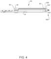
- FIG. 4is a perspective view of components of one embodiment of a surgical system in accordance with the principles of the present disclosure
- FIG. 5is a break-away perspective view of components of one embodiment of a surgical system in accordance with the principles of the present disclosure
- FIG. 6is a perspective view of components of one embodiment of a surgical system in accordance with the principles of the present disclosure
- FIG. 7is a perspective view of components of one embodiment of a surgical system in accordance with the principles of the present disclosure being handled by a user;
- FIG. 8is a break-away perspective view, partly in phantom, of components of one embodiment of a surgical system in accordance with the principles of the present disclosure
- FIG. 10is a detail view of the components shown in FIG. 9 ;
- FIG. 13is a perspective view, part in phantom, of components of one embodiment of a surgical system in accordance with the principles of the present disclosure
- Surgical system 10is employed, for example, with a minimally invasive procedure, including percutaneous techniques, mini-open and open surgical techniques to deliver and introduce instrumentation and/or components of spinal constructs at a surgical site within a patient body of a patient, for example, a section of a spine.
- one or more of the components of surgical system 10are configured for engagement with spinal constructs attached with vertebrae to manipulate tissue and/or correct a spinal disorder, such as, for example, a sagittal deformity, as described herein.
- surgical system 10may be employed with surgical procedures, such as, for example, corpectomy, discectomy and/or fracture/trauma treatment and may include fusion and/or fixation that employ implants to restore the mechanical support function of vertebrae.
- Surgical system 10includes an extender, such as, for example, an implant support 14 and an implant support 14 a ( FIG. 6 ), similar to implant support 14 , as described herein, and a sleeve 80 ( FIG. 3 ), both engageable with separate and spaced apart bone screws 600 ( FIGS. 4 and 6 ).
- Implant supports 14 , 14 aare connectable to surgical instruments, such as, for example, a distractor 250 ( FIGS. 5 and 6 ) and/or a compression instrument 1000 to facilitate manipulation of tissue, as described herein.
- Implant support 14extends along an axis X 1 , as shown in FIG. 1 .
- Implant support 14includes a first extension 20 and a second extension 22 , as shown in FIG. 2 .
- Extensions 20 , 22are moveable relative to each other, via relative translation of a translation element, such as, for example, a slide 26 disposed with implant support 14 , as shown in FIG. 2 .
- Slide 26is manipulated for translation within a channel 28 to move extensions 20 , 22 between an open orientation and a closed, capture orientation. Slide 26 is translated, in a direction shown by arrow A in FIG. 2 , to cause extensions 20 , 22 to rotate and expand, in a direction shown by arrows B, to the open orientation.
- pins 30In the open orientation, pins 30 , connected with extensions 20 , 22 , are disposed in a bottom of slots 32 of slide 26 .
- Slide 26is translated, in a direction shown by arrow C in FIG. 2 , to cause extensions 20 , 22 to rotate and contract, in a direction shown by arrows D, to the closed orientation to capture a wall 604 of a receiver 602 of bone screw 600 , as shown in FIG. 2 .
- pins 30In the closed orientation, pins 30 are disposed at the top of slots 32 .
- extensions 20 , 22are flexible to facilitate contraction.
- Implant support 14is connected with wall 604 , as described herein in connection with FIGS. 3 and 4 , so as to not block direct access to an implant cavity (between walls 604 and 606 ) of receiver 602 to facilitate insertion of an implant, such as a spinal rod, and perhaps also a securing device, such as a set cap or setscrew.
- an implantsuch as a spinal rod
- a securing devicesuch as a set cap or setscrew.
- one or more implant supports 14are manipulable, as described herein, to provide a counter-torque for small deformity maneuvers and manipulation of vertebrae during a surgical treatment, for example, to displace, pull, twist or align vertebrae.
- flanges 88 , 90are flexible such that flanges 88 , 90 snap fit around and into engagement with implant support 14 .
- sleeve 80is disposed in a configuration to capture a wall 606 of receiver 602 , as shown in FIG. 4 .
- End 86includes a surface 100 that defines a mating surface 102 .
- Surface 102is configured for capture of wall 606 .
- surface 102includes a distal projection 104 configured for engagement with a cavity 608 ( FIG. 2 ) of wall 606 of receiver 602 to facilitate engagement.
- bone screw 600includes a shaft 610 and receiver 602 .
- Receiver 602is moveable relative to shaft in a multi axial configuration.
- Receiver 602is configured for engagement with implant support 14 and sleeve 80 , as described herein.
- At least one of the walls 604 , 606includes a surface that defines cavity 608 ( FIG. 2 ). Each cavity 608 can be used to facilitate connection with implant support 14 and/or sleeve 80 , as described herein.
- Walls 604 , 606include an inner surface that defines a U-shaped passageway 612 for disposal of a spinal rod, as described herein.
- the inner surface of receiver 602includes a thread form configured for engagement with a set screw.
- surgical system 10In assembly, operation and use, surgical system 10 , similar to the systems and methods described herein, is employed with a surgical procedure, for treatment of a spine of a patient including vertebrae V, as shown in FIGS. 8 - 19 .
- Surgical system 10may also be employed with surgical procedures, such as, for example, discectomy, laminectomy, fusion, laminotomy, laminectomy, nerve root retraction, foramenotomy, facetectomy, decompression, spinal nucleus or disc replacement and bone graft and implantable prosthetics including plates, rods, and bone engaging fasteners.
- Surgical system 10is employed with a procedure for treatment of an applicable condition or injury of an affected section of a spinal column and adjacent areas within a body.
- vertebrae Vincludes a vertebral level V 1 , a vertebral level V 2 and a vertebral level V 3 , as shown in FIG. 19 .
- Diseased and/or damaged vertebrae and intervertebral discsare disposed at vertebra V 2 between vertebrae V 1 and V 3 .
- components of surgical system 10are configured for insertion with a vertebral space to space apart articular joint surfaces, provide support and maximize stabilization of vertebrae V.
- surgical system 10may be used in any existing surgical method or technique including open surgery, mini-open surgery, minimally invasive surgery and percutaneous surgical implantation, whereby vertebrae V is accessed through a mini-incision, or sleeve that provides a protected passageway to the area.
- a cutting instrument(not shown) creates a surgical pathway for implantation of components of surgical system 10 .
- a preparation instrument(not shown) can be employed to prepare tissue surfaces of vertebrae V, as well as for aspiration and irrigation of a surgical region.
- Implant supports 14 , 14 aare engaged with wall 604 of receiver 602 , as described herein.
- Sleeves 80are engaged with wall 606 of receiver 602 , as described herein.
- Mating grooves 88 , 90are engaged with implant support 14 , as described herein.
- a driver 650is disposed adjacent vertebrae V at a surgical site and is manipulated to drive, torque, insert or otherwise connect bone screw 600 with vertebrae.
- a distractor 250is connected with implant supports 14 , 14 a , to allow for distraction of vertebrae V connected with bone screws 600 .
- Distractor 250includes a longitudinal element, such as, for example, a rack 252 extending between an end 254 and an end 256 .
- Rack 252is configured to connect adjacent implant supports 14 , 14 a .
- Rack 252includes an outer surface 258 having a plurality of teeth, such as, for example, splines 260 engageable with an arm 282 , as described herein.
- Rack 252includes an arm 262 extending from end 254 . In some embodiments, arm 262 is attached with rack 252 with, for example, with clips, hooks, adhesives and/or flanges.
- Arm 262includes a member, such as, for example, an adaptor 270 extending between an end 272 and an end 274 .
- Adaptor 270includes a surface 276 and walls 278 that defines a receiver 280 extending between ends 272 , 274 .
- Receiver 280is configured for disposal of implant support 14 a .
- Adaptor 270includes a rectangular cross section configuration, as shown in FIG. 5 . In some embodiments, all or only a portion of the cross section of adaptor 270 may have alternate cross section configurations, such as, for example, arcuate, closed, V-shaped, W-shaped, oval, oblong triangular, square, polygonal, irregular, uniform, non-uniform, offset, staggered, and/or tapered.
- Rack 252includes arm 282 that is axially translatable relative to arm 162 .
- Arm 262includes a member, such as, for example, an adaptor 290 extending between an end 292 and an end 294 .
- Adaptor 290includes a surface 296 and walls 298 that define a receiver 300 extending between ends 292 , 294 .
- Receiver 300is configured for disposal of implant support 14 .
- Adaptor 290includes a rectangular cross section configuration, as shown in FIG. 5 .
- all or only a portion of the cross section of adaptor 290may have alternate cross section configurations, such as, for example, arcuate, closed, V-shaped, W-shaped, oval, oblong triangular, square, polygonal, irregular, uniform, non-uniform, offset, staggered, and/or tapered.
- implant support 14is disposed with adaptor 290 and implant support 14 a is disposed with adaptor 270 , as shown in FIG. 6 .
- Bone screws 600 with multi-axial receivers 602facilitate manipulation of implant supports 14 , 14 a for engagement with adaptors 270 , 290 .
- Rack 252includes a latch 302 that is pivotable relative to arm 282 for disposal in a distraction position, as shown in FIG. 6 . In the distraction position, latch 302 engages rack 252 to allow axial and/or incremental translation of arm 282 relative to arm 262 /rack 252 and prevents axial translation of arm 282 relative to arm 262 /rack 252 , in an opposing direction.
- latch 300is pivotable to the distraction position, as described herein, to allow translation of arm 282 , in the direction shown by arrow E in FIG. 6 , and prevent translation of arm 282 , in the direction shown by arrow F, relative to arm 262 /rack 252 .
- distraction of vertebrae V 1 , V 3which are connected with implant supports 14 , 14 a , can be performed.
- a dilator(not shown) is inserted between implant supports 14 , 14 a into contact with bony anatomy and determine tissue depth.
- a retractor blades(not shown) are translated along the dilator into engagement with the bony anatomy. The blades are disposed with tissue to form a surgical passageway to facilitate insertion of a spinal implant, such as, for example, an interbody spinal implant.
- a rod inserter(not shown) is engaged with a spinal rod 450 to direct and/or guide spinal rod 450 through implant supports 14 , 14 a into receiver 602 .
- Sleeve 80is disengaged from implant support 14 , as shown in FIG. 14 .
- a driver(not shown) is utilized to engage a set screw 601 with bone screw 600 to fix one end of spinal rod 450 disposed with bone screw 600 connected with implant support 14 , as shown in FIG. 8 .
- Implant supports 14 , 14 aare crossed and a compression instrument 1000 is disposed with implant supports 14 , 14 a , as shown in FIGS. 8 - 11 .
- Instrument 1000is configured to facilitate compression of vertebrae V via connection with implant supports 14 , 14 a .
- Instrument 1000includes a member, such as, for example, a pivot body 1002 configured to facilitate rotation of implant support 14 a relative to body 1002 .
- Body 1002extends between an end 1004 and an end 1006 and defines an axis X 10 .
- Body 1002includes a surface 1010 that defines a cavity, such as, for example, an opening 1012 .
- Opening 1012extends between end 1004 and end 1006 .
- Opening 1012is configured for disposal with a proximal end of implant support 14 .
- Body 1002includes a lock, such as, for example a pair of depressible buttons 1020 configured connection with implant support 14 .
- Buttons 1020are disposable between a lock or locking orientation and a non-locking orientation. In the lock orientation, buttons 1020 releasably fix body 1002 with implant support 14 . In the non-locking orientation, body 1002 is translatable and/or removable from implant support 14 .
- Button 1020may be spring biased to a locked position, such as by a projection 1022 defined by button 1020 being biased in the lock orientation into engagement with a groove 1024 , shown in FIG. 13 , of implant support 14 to releasably fix implant support 14 with body 1002 .
- Buttons 1020are configured to resist and/or prevent body 1002 from disengaging from implant support 14 .
- an outer surface of body 1002includes one or a plurality of buttons 1020 .
- body 1002may include ridges to facilitate gripping of body 1002 , for example, to manipulate body 1002 relative to implant support 14 , as described herein.
- End 1006includes arms 1030 .
- Arms 1030include a surface 1032 that define a receiver 1034 .
- Arms 1030extend transverse to axis X 10 .
- arms 1030may be variously oriented relative to axis X 10 , such as, for example, perpendicular, angular and/or offset.
- Receiver 1034is configured for engagement with implant support 14 a .
- surface 1032defines a cavity having a concave configuration to facilitate engagement with a surface of implant support 14 a to facilitate crossing of implant support 14 a with implant support 14 .
- receiver 1034may include alternate configurations, such as, for example, arcuate, offset, staggered and/or angled portions.
- Body 1002includes a housing 1040 .
- Housing 1040includes a surface 1042 that defines an opening, such as, for example, a passageway 1044 .
- Passageway 1044is configured for moveable disposal of an actuator 1046 and a part, such as, for example, a slider 1048 .
- Surface 1042includes a thread form (not shown) engageable with actuator 1046 to facilitate translation of slider 1048 , as described herein.
- Actuator 1046includes a shaft 1050 that extends between an end 1052 and an end 1054 .
- Shaft 1050includes a threaded surface 1056 engageable with surface 1042 to facilitate translation.
- End 1052includes a knob 1058 to facilitate rotation of actuator 1046 .
- End 1054includes slider 1048 .
- Slider 1048includes arms 1060 .
- Arms 1060include a surface 1062 that define a receiver 1064 .
- Arms 1060extend transverse to shaft 1050 .
- arms 1060may be variously oriented relative to shaft 1050 , such as, for example, perpendicular, angular and/or offset.
- Receiver 1064is configured for engagement with implant support 14 a .
- surface 1062defines a cavity having a concave configuration to facilitate engagement with a surface of implant support 14 a .
- Slider 1048is actuated to translate along implant support 14 causing rotation of implant support 14 a within receiver 1034 to facilitate compression of vertebrae.
- receiver 1064may include alternate configurations, such as, for example, arcuate, offset, staggered and/or angled portions.
- body 1002is translated over implant support 14 , as shown by arrow G in FIG. 9 , such that implant support 14 is disposed with opening 1012 .
- Buttons 1020snap into the lock position to fix instrument 1000 with implant support 14 .
- Slider 1048is disposed in an initial orientation such that receivers 1034 , 1064 are disposed adjacent each other.
- Implant support 14 ais disposed with receivers 1034 , 1064 , as shown in FIGS. 9 and 10 , such that implant supports 14 , 14 a are captured by receivers 1034 , 1064 .
- receivers 602are disposed a relative distance D 1 .
- distance D 1is about 50 mm.
- shafts 610are disposed at a relative angle ⁇ 1 . In some embodiments, angle ⁇ 1 is about 27 degrees.
- Actuator 1046is rotated, as shown by arrow H in FIG. 9 , causing threaded shaft 1050 to engage the threaded surface of housing 1040 .
- Rotation of shaft 1050causes slider 1048 to translate, in a direction shown by arrow I in FIGS. 11 and 12 .
- Slider 1048translates along implant support 14 a causing further selective compression of vertebrae V.
- Receiver 1062translates causing rotation of implant support 14 a relative to instrument 1000 .
- receivers 602are disposed a relative distance D 2 . In some embodiments, distance D 2 is about 35 mm.
- shafts 610are disposed at a relative angle ⁇ 2 . In some embodiments, angle ⁇ 2 is about 16 degrees.
- Actuator 1046is further rotated, as shown by arrow J in FIG. 11 , causing threaded shaft 1050 to engage the threaded surface of housing 1040 .
- Rotation of shaft 1050causes slider 1048 to translate, in a direction shown by arrow L in FIGS. 14 and 15 .
- Slider 1048translates along implant support 14 a causing selective compression of vertebrae V.
- Receiver 1062translates away from receiver 1034 causing rotation of implant support 14 a relative to instrument 1000 .
- receivers 602are disposed a relative distance D 3 . In some embodiments, distance D 3 is about 19 mm.
- shafts 610are disposed at a relative angle ⁇ 3 . In some embodiments, angle ⁇ 3 is about 8 degrees.
- Compression instrument 1000 and implant supports 14are removed, as shown in FIG. 16 .
- Spinal rodis fixed with bone screws 600 .
- surgical system 10Upon completion of a procedure, as described herein, the surgical instruments, assemblies and non-implanted components of surgical system 10 are removed and the incision(s) are closed.
- One or more of the components of surgical system 10can be made of radiolucent materials such as polymers. Radiomarkers may be included for identification under x-ray, fluoroscopy, CT or other imaging techniques.
- the use of surgical navigation, microsurgical and image guided technologiesmay be employed to access, view and repair spinal deterioration or damage, with the aid of surgical system 10 .
- surgical system 10may include one or a plurality of plates, connectors and/or bone fasteners for use with a single vertebral level or a plurality of vertebral levels.
- surgical system 10includes one or a plurality of alternate surgical instruments, each configured for mating engagement in a quick release configuration with spinal constructs, as described herein. This configuration facilitates the interchangeability of the spinal constructs with the alternate surgical instruments.
- surgical system 10includes one or a plurality of alternate surgical instruments, such as, for example, inserters, extenders, reducers, spreaders, distractors, blades, retractors, clamps, forceps, elevators and drills, which may be alternately sized and dimensioned, and arranged as a kit.
Landscapes
- Health & Medical Sciences (AREA)
- Orthopedic Medicine & Surgery (AREA)
- Neurology (AREA)
- Life Sciences & Earth Sciences (AREA)
- Surgery (AREA)
- Heart & Thoracic Surgery (AREA)
- Engineering & Computer Science (AREA)
- Biomedical Technology (AREA)
- Nuclear Medicine, Radiotherapy & Molecular Imaging (AREA)
- Medical Informatics (AREA)
- Molecular Biology (AREA)
- Animal Behavior & Ethology (AREA)
- General Health & Medical Sciences (AREA)
- Public Health (AREA)
- Veterinary Medicine (AREA)
- Surgical Instruments (AREA)
- Prostheses (AREA)
Abstract
Description
Claims (20)
Applications Claiming Priority (1)
| Application Number | Priority Date | Filing Date | Title |
|---|---|---|---|
| PCT/US2019/028632WO2020219020A1 (en) | 2019-04-23 | 2019-04-23 | Surgical system and method |
Publications (2)
| Publication Number | Publication Date |
|---|---|
| US20220202450A1 US20220202450A1 (en) | 2022-06-30 |
| US12349942B2true US12349942B2 (en) | 2025-07-08 |
Family
ID=72940785
Family Applications (1)
| Application Number | Title | Priority Date | Filing Date |
|---|---|---|---|
| US17/606,013Active2039-08-15US12349942B2 (en) | 2019-04-23 | 2019-04-23 | Surgical system and method |
Country Status (4)
| Country | Link |
|---|---|
| US (1) | US12349942B2 (en) |
| EP (1) | EP3958757B1 (en) |
| CN (1) | CN113710177B (en) |
| WO (1) | WO2020219020A1 (en) |
Families Citing this family (8)
| Publication number | Priority date | Publication date | Assignee | Title |
|---|---|---|---|---|
| EP3958761B1 (en) | 2019-04-23 | 2023-11-15 | Warsaw Orthopedic, Inc. | Surgical system |
| EP3958757B1 (en) | 2019-04-23 | 2024-11-27 | Warsaw Orthopedic, Inc. | Surgical system |
| EP3958758A4 (en) | 2019-04-23 | 2022-12-07 | Warsaw Orthopedic, Inc. | Surgical system and method |
| WO2020219019A1 (en) | 2019-04-23 | 2020-10-29 | Warsaw Orthopedic, Inc. | Surgical system and method |
| WO2021206723A1 (en) | 2020-04-09 | 2021-10-14 | Warsaw Orthopedic, Inc. | Surgical system and method |
| US12096923B2 (en) | 2020-07-10 | 2024-09-24 | Warsaw Orthopedic, Inc. | Tissue retractor, retraction modules, and associated methods |
| US12349889B2 (en) | 2020-07-10 | 2025-07-08 | Warsaw Orthopedic, Inc. | Tissue retractor, retraction modules, and associated methods |
| US12383249B2 (en) | 2020-07-10 | 2025-08-12 | Warsaw Orthopedic, Inc. | Tissue retractor, retraction modules, and associated methods |
Citations (62)
| Publication number | Priority date | Publication date | Assignee | Title |
|---|---|---|---|---|
| WO1990002527A1 (en) | 1988-09-09 | 1990-03-22 | Australian Defence Industries Pty. Limited | Spinal distractor |
| US6030402A (en) | 1998-04-23 | 2000-02-29 | Thompson; Ronald J. | Apparatus and methods for the penetration of tissue, and the creation of an opening therein |
| US6139493A (en) | 1998-07-08 | 2000-10-31 | Koros; Tibor B. | Retractor with adjustable length blades and light pipe guides |
| US20060084844A1 (en) | 2004-10-19 | 2006-04-20 | Nehls Daniel G | Retractor and distractor system for use in anterior cervical disc surgery |
| WO2007087536A2 (en) | 2006-01-23 | 2007-08-02 | Pioneer Surgical Technology, Inc. | Retraction apparatus and method of use |
| US20070208227A1 (en) | 2002-07-11 | 2007-09-06 | Nuvasive, Inc. | Surgical access system and related methods |
| US20080140129A1 (en)* | 2003-07-07 | 2008-06-12 | Aesculap Implant Systems, Inc. | Spinal stabilization implant and method of application |
| CN101489497A (en) | 2006-04-11 | 2009-07-22 | 新特斯有限责任公司 | Minimally invasive fixation system |
| US20100069976A1 (en) | 2003-01-31 | 2010-03-18 | Spinalmotion, Inc. | Intervertebral Prosthesis Placement Instrument |
| US20120296172A1 (en) | 2011-05-20 | 2012-11-22 | Raven Iii Raymond B | Surgical retractor apparatus and method |
| US20120316609A1 (en) | 2011-06-13 | 2012-12-13 | Warsaw Orthopedic, Inc. | Surgical instrument for securing a spinal rod |
| US20130310942A1 (en) | 2009-12-07 | 2013-11-21 | Samy Abdou | Devices and methods for minimally invasive spinal stabilization and instrumentation |
| US20140024900A1 (en) | 2012-07-17 | 2014-01-23 | Warsaw Orthopedic, Inc. | Surgical retractor and method of use |
| US20140066718A1 (en) | 2012-09-06 | 2014-03-06 | Medacta International Sa | Surgical device for minimally invasive spinal fusion and surgical system comprising the same |
| US20140107656A1 (en) | 2012-10-16 | 2014-04-17 | Robert Masson | Pop on spreader system |
| US20140257044A1 (en) | 2006-09-25 | 2014-09-11 | Spinal Elements, Inc. | Retractor |
| US20140257312A1 (en)* | 2013-03-11 | 2014-09-11 | Ralph C. Solitario, Jr. | Vertebral manipulation assembly |
| KR101446620B1 (en) | 2006-12-21 | 2014-10-01 | 엘디알 메디칼, 에스.에이.에스. | Spinal support device |
| US20140350347A1 (en) | 2010-03-11 | 2014-11-27 | Globus Medical, Inc | Tissue Retractor and Methods of Use |
| US20150045834A1 (en) | 2013-08-06 | 2015-02-12 | Warsaw Orthopedic, Inc. | Spinal implant system |
| US20150164569A1 (en) | 2013-12-13 | 2015-06-18 | Stryker European Holdings I, Llc | Tissue retraction and vertebral displacement devices, systems, and methods for posterior spinal fusion |
| US20150351738A1 (en) | 2011-03-08 | 2015-12-10 | Pioneer Surgical Technology, Inc. | Apparatus and Method for Enlarging an Incision |
| GB2528416A (en) | 2010-11-10 | 2016-01-20 | Nuvasive Inc | Method and apparatus for performing spinal surgery |
| US20160074029A1 (en) | 2014-08-13 | 2016-03-17 | Nuvasive, Inc. | Minimally disruptive retractor and associated methods for spinal surgery |
| US20160089188A1 (en) | 2014-09-25 | 2016-03-31 | Warsaw Orthopedic, Inc. | Spinal implant system and method |
| US20160166335A1 (en) | 2013-07-09 | 2016-06-16 | Cryptych Pty Ltd | Spinal Surgery Navigation |
| US20160206442A1 (en) | 2015-01-20 | 2016-07-21 | Warsaw Orthopedic, Inc. | Spinal implant system and method |
| US9402660B2 (en) | 2013-09-05 | 2016-08-02 | Warsaw Orthopedic, Inc. | Surgical instrument and method |
| US20160345952A1 (en) | 2014-01-29 | 2016-12-01 | Spinal Usa, Inc. | Minimally invasive devices, systems and methods for treating the spine |
| US20170035406A1 (en) | 2014-05-01 | 2017-02-09 | Blackstone Medical, Inc. | Integrated retractor-distractor system for use with modular bone screws |
| US20170100116A1 (en) | 2015-10-07 | 2017-04-13 | Medos International Sarl | Systems and methods for manipulating bone |
| US20170112539A1 (en) | 2013-11-12 | 2017-04-27 | Alphatec Spine, Inc. | Spondylisthesis Reduction System |
| US20170119449A1 (en)* | 2004-12-02 | 2017-05-04 | Zimmer Spine, Inc. | Instruments and methods for adjusting separation distance of vertebral bodies with a minimally invasive spinal stabilization procedure |
| US20170215856A1 (en) | 2004-10-08 | 2017-08-03 | Nuvasive, Inc. | Surgical Access System and Related Methods |
| US20170252107A1 (en) | 2016-03-02 | 2017-09-07 | Nuvasive, Inc. | Systems and Methods for Spinal Correction Surgical Planning |
| US20170258502A1 (en) | 2007-02-26 | 2017-09-14 | Nuvasive, Inc. | Spinal Stabilization System and Methods of Use |
| US20170311985A1 (en) | 2016-04-27 | 2017-11-02 | Warsaw Orthopedic, Inc | Spinal correction system and method |
| US20180042594A1 (en) | 2003-01-16 | 2018-02-15 | Nuvasive, Inc. | Surgical access system and related methods |
| EP3331421A2 (en) | 2015-08-06 | 2018-06-13 | Nuvasive, Inc. | Minimally disruptive retractor and associated methods for spinal surgery |
| US20180161101A1 (en) | 2016-12-08 | 2018-06-14 | The Cleveland Clinic Foundation | Model-based surgical planning and implant placement |
| EP3351185A1 (en) | 2014-03-03 | 2018-07-25 | Alphatec Spine, Inc. | Soft tissue retractor |
| WO2018150215A1 (en) | 2017-02-17 | 2018-08-23 | Warsaw Orthopedic, Inc. | Surgical system and method |
| WO2018150214A1 (en) | 2017-02-17 | 2018-08-23 | Warsaw Orthopedic, Inc. | Surgical system |
| CN108498152A (en) | 2017-02-24 | 2018-09-07 | 华沙整形外科股份有限公司 | spinal implant system and method |
| US20180289363A1 (en) | 2015-10-06 | 2018-10-11 | K2M, Inc. | Surgical access system, devices thereof, and methods of using the same |
| US20180303473A1 (en) | 2017-04-19 | 2018-10-25 | Pantheon Spinal, Llc | Spine Surgery Retractor System and Related Methods |
| US20180303552A1 (en) | 2017-04-21 | 2018-10-25 | Medicrea International | Systems, methods, and devices for developing patient-specific spinal treatments, operations, and procedures |
| US20190021716A1 (en) | 2013-10-07 | 2019-01-24 | Warsaw Orthopedic, Inc. | Spinal implant system and method for lumbar and lumbosacral fusion |
| US20190038366A1 (en) | 2012-06-21 | 2019-02-07 | Globus Medical, Inc. | Surgical robotic automation with tracking markers |
| US20190090864A1 (en) | 2017-09-22 | 2019-03-28 | Medos International Sarl | Patient-mounted surgical retractor |
| US20190090979A1 (en) | 2017-09-22 | 2019-03-28 | Medos International Sarl | Patient-mounted surgical support |
| US20190110785A1 (en) | 2017-10-18 | 2019-04-18 | Spine Wave, Inc. | Screw-based retractor with expandable blades |
| US20190216453A1 (en) | 2011-12-20 | 2019-07-18 | Life Spine, Inc. | Retractor with modular tap assemblies |
| US20190223854A1 (en) | 2010-09-20 | 2019-07-25 | DePuy Synthes Products, Inc. | Spinal Access Retractor |
| CN110381866A (en) | 2017-03-08 | 2019-10-25 | 美多斯国际有限公司 | Surgery entrance is stablized |
| US20200085500A1 (en) | 2018-02-14 | 2020-03-19 | Warsaw Orthopedic, Inc | Spinal implant system and methods of use |
| WO2020219016A1 (en) | 2019-04-23 | 2020-10-29 | Warsaw Orthopedic, Inc. | Surgical system and method |
| WO2020219018A1 (en) | 2019-04-23 | 2020-10-29 | Warsaw Orthopedic, Inc. | Surgical system and method |
| WO2020219019A1 (en) | 2019-04-23 | 2020-10-29 | Warsaw Orthopedic, Inc. | Surgical system and method |
| WO2020219020A1 (en) | 2019-04-23 | 2020-10-29 | Warsaw Orthopedic, Inc. | Surgical system and method |
| WO2021206723A1 (en) | 2020-04-09 | 2021-10-14 | Warsaw Orthopedic, Inc. | Surgical system and method |
| US20220218417A1 (en) | 2019-04-23 | 2022-07-14 | Warsaw Orthopedic, Inc. | Surgical system and method |
- 2019
- 2019-04-23EPEP19925589.4Apatent/EP3958757B1/enactiveActive
- 2019-04-23CNCN201980095623.2Apatent/CN113710177B/enactiveActive
- 2019-04-23WOPCT/US2019/028632patent/WO2020219020A1/ennot_activeCeased
- 2019-04-23USUS17/606,013patent/US12349942B2/enactiveActive
Patent Citations (72)
| Publication number | Priority date | Publication date | Assignee | Title |
|---|---|---|---|---|
| WO1990002527A1 (en) | 1988-09-09 | 1990-03-22 | Australian Defence Industries Pty. Limited | Spinal distractor |
| US6030402A (en) | 1998-04-23 | 2000-02-29 | Thompson; Ronald J. | Apparatus and methods for the penetration of tissue, and the creation of an opening therein |
| US6139493A (en) | 1998-07-08 | 2000-10-31 | Koros; Tibor B. | Retractor with adjustable length blades and light pipe guides |
| US20070208227A1 (en) | 2002-07-11 | 2007-09-06 | Nuvasive, Inc. | Surgical access system and related methods |
| US20180042594A1 (en) | 2003-01-16 | 2018-02-15 | Nuvasive, Inc. | Surgical access system and related methods |
| US20100069976A1 (en) | 2003-01-31 | 2010-03-18 | Spinalmotion, Inc. | Intervertebral Prosthesis Placement Instrument |
| US20080140129A1 (en)* | 2003-07-07 | 2008-06-12 | Aesculap Implant Systems, Inc. | Spinal stabilization implant and method of application |
| US20170215856A1 (en) | 2004-10-08 | 2017-08-03 | Nuvasive, Inc. | Surgical Access System and Related Methods |
| US20060084844A1 (en) | 2004-10-19 | 2006-04-20 | Nehls Daniel G | Retractor and distractor system for use in anterior cervical disc surgery |
| US20170119449A1 (en)* | 2004-12-02 | 2017-05-04 | Zimmer Spine, Inc. | Instruments and methods for adjusting separation distance of vertebral bodies with a minimally invasive spinal stabilization procedure |
| WO2007087536A2 (en) | 2006-01-23 | 2007-08-02 | Pioneer Surgical Technology, Inc. | Retraction apparatus and method of use |
| CN101489497A (en) | 2006-04-11 | 2009-07-22 | 新特斯有限责任公司 | Minimally invasive fixation system |
| US20140257044A1 (en) | 2006-09-25 | 2014-09-11 | Spinal Elements, Inc. | Retractor |
| KR101446620B1 (en) | 2006-12-21 | 2014-10-01 | 엘디알 메디칼, 에스.에이.에스. | Spinal support device |
| US10314620B2 (en) | 2006-12-21 | 2019-06-11 | Ldr Medical | Vertebral support device |
| US8974497B2 (en) | 2006-12-21 | 2015-03-10 | Ldr Medical | Vertebral support device |
| US20170258502A1 (en) | 2007-02-26 | 2017-09-14 | Nuvasive, Inc. | Spinal Stabilization System and Methods of Use |
| US20130310942A1 (en) | 2009-12-07 | 2013-11-21 | Samy Abdou | Devices and methods for minimally invasive spinal stabilization and instrumentation |
| US20140350347A1 (en) | 2010-03-11 | 2014-11-27 | Globus Medical, Inc | Tissue Retractor and Methods of Use |
| US20190223854A1 (en) | 2010-09-20 | 2019-07-25 | DePuy Synthes Products, Inc. | Spinal Access Retractor |
| GB2528416A (en) | 2010-11-10 | 2016-01-20 | Nuvasive Inc | Method and apparatus for performing spinal surgery |
| US20150351738A1 (en) | 2011-03-08 | 2015-12-10 | Pioneer Surgical Technology, Inc. | Apparatus and Method for Enlarging an Incision |
| US20120296172A1 (en) | 2011-05-20 | 2012-11-22 | Raven Iii Raymond B | Surgical retractor apparatus and method |
| US20120316609A1 (en) | 2011-06-13 | 2012-12-13 | Warsaw Orthopedic, Inc. | Surgical instrument for securing a spinal rod |
| US20190216453A1 (en) | 2011-12-20 | 2019-07-18 | Life Spine, Inc. | Retractor with modular tap assemblies |
| US20190038366A1 (en) | 2012-06-21 | 2019-02-07 | Globus Medical, Inc. | Surgical robotic automation with tracking markers |
| US20140024900A1 (en) | 2012-07-17 | 2014-01-23 | Warsaw Orthopedic, Inc. | Surgical retractor and method of use |
| US20140066718A1 (en) | 2012-09-06 | 2014-03-06 | Medacta International Sa | Surgical device for minimally invasive spinal fusion and surgical system comprising the same |
| US20140107656A1 (en) | 2012-10-16 | 2014-04-17 | Robert Masson | Pop on spreader system |
| US20140257312A1 (en)* | 2013-03-11 | 2014-09-11 | Ralph C. Solitario, Jr. | Vertebral manipulation assembly |
| US20160166335A1 (en) | 2013-07-09 | 2016-06-16 | Cryptych Pty Ltd | Spinal Surgery Navigation |
| US20150045834A1 (en) | 2013-08-06 | 2015-02-12 | Warsaw Orthopedic, Inc. | Spinal implant system |
| US9402660B2 (en) | 2013-09-05 | 2016-08-02 | Warsaw Orthopedic, Inc. | Surgical instrument and method |
| US20190021716A1 (en) | 2013-10-07 | 2019-01-24 | Warsaw Orthopedic, Inc. | Spinal implant system and method for lumbar and lumbosacral fusion |
| US20170112539A1 (en) | 2013-11-12 | 2017-04-27 | Alphatec Spine, Inc. | Spondylisthesis Reduction System |
| US20150164569A1 (en) | 2013-12-13 | 2015-06-18 | Stryker European Holdings I, Llc | Tissue retraction and vertebral displacement devices, systems, and methods for posterior spinal fusion |
| US20160345952A1 (en) | 2014-01-29 | 2016-12-01 | Spinal Usa, Inc. | Minimally invasive devices, systems and methods for treating the spine |
| EP3351185A1 (en) | 2014-03-03 | 2018-07-25 | Alphatec Spine, Inc. | Soft tissue retractor |
| US20170035406A1 (en) | 2014-05-01 | 2017-02-09 | Blackstone Medical, Inc. | Integrated retractor-distractor system for use with modular bone screws |
| US20160074029A1 (en) | 2014-08-13 | 2016-03-17 | Nuvasive, Inc. | Minimally disruptive retractor and associated methods for spinal surgery |
| US20160089188A1 (en) | 2014-09-25 | 2016-03-31 | Warsaw Orthopedic, Inc. | Spinal implant system and method |
| US20160206442A1 (en) | 2015-01-20 | 2016-07-21 | Warsaw Orthopedic, Inc. | Spinal implant system and method |
| EP3331421A2 (en) | 2015-08-06 | 2018-06-13 | Nuvasive, Inc. | Minimally disruptive retractor and associated methods for spinal surgery |
| US20180289363A1 (en) | 2015-10-06 | 2018-10-11 | K2M, Inc. | Surgical access system, devices thereof, and methods of using the same |
| US20170100116A1 (en) | 2015-10-07 | 2017-04-13 | Medos International Sarl | Systems and methods for manipulating bone |
| US20170252107A1 (en) | 2016-03-02 | 2017-09-07 | Nuvasive, Inc. | Systems and Methods for Spinal Correction Surgical Planning |
| US11576727B2 (en) | 2016-03-02 | 2023-02-14 | Nuvasive, Inc. | Systems and methods for spinal correction surgical planning |
| US20190046239A1 (en) | 2016-04-27 | 2019-02-14 | Warsaw Orthopedic, Inc. | Spinal correction system and method |
| US20170311985A1 (en) | 2016-04-27 | 2017-11-02 | Warsaw Orthopedic, Inc | Spinal correction system and method |
| US20180161101A1 (en) | 2016-12-08 | 2018-06-14 | The Cleveland Clinic Foundation | Model-based surgical planning and implant placement |
| WO2018150214A1 (en) | 2017-02-17 | 2018-08-23 | Warsaw Orthopedic, Inc. | Surgical system |
| US20200054361A1 (en) | 2017-02-17 | 2020-02-20 | Warsaw Orthopedic, Inc. | Surgical System |
| WO2018150215A1 (en) | 2017-02-17 | 2018-08-23 | Warsaw Orthopedic, Inc. | Surgical system and method |
| CN108498152A (en) | 2017-02-24 | 2018-09-07 | 华沙整形外科股份有限公司 | spinal implant system and method |
| CN110381866A (en) | 2017-03-08 | 2019-10-25 | 美多斯国际有限公司 | Surgery entrance is stablized |
| US20180303473A1 (en) | 2017-04-19 | 2018-10-25 | Pantheon Spinal, Llc | Spine Surgery Retractor System and Related Methods |
| US20180303552A1 (en) | 2017-04-21 | 2018-10-25 | Medicrea International | Systems, methods, and devices for developing patient-specific spinal treatments, operations, and procedures |
| US20190069956A1 (en) | 2017-04-21 | 2019-03-07 | Medicrea International | Systems, methods, and devices for developing patient-specific spinal treatments, operations, and procedures |
| US20190090864A1 (en) | 2017-09-22 | 2019-03-28 | Medos International Sarl | Patient-mounted surgical retractor |
| US20190090979A1 (en) | 2017-09-22 | 2019-03-28 | Medos International Sarl | Patient-mounted surgical support |
| US20190110785A1 (en) | 2017-10-18 | 2019-04-18 | Spine Wave, Inc. | Screw-based retractor with expandable blades |
| US20200085500A1 (en) | 2018-02-14 | 2020-03-19 | Warsaw Orthopedic, Inc | Spinal implant system and methods of use |
| US20220218417A1 (en) | 2019-04-23 | 2022-07-14 | Warsaw Orthopedic, Inc. | Surgical system and method |
| WO2020219019A1 (en) | 2019-04-23 | 2020-10-29 | Warsaw Orthopedic, Inc. | Surgical system and method |
| WO2020219020A1 (en) | 2019-04-23 | 2020-10-29 | Warsaw Orthopedic, Inc. | Surgical system and method |
| US20220192645A1 (en) | 2019-04-23 | 2022-06-23 | Warsaw Orthopedic, Inc. | Surgical system and method |
| US20220202405A1 (en) | 2019-04-23 | 2022-06-30 | Warsaw Orthopedic, Inc. | Surgical system and method |
| WO2020219018A1 (en) | 2019-04-23 | 2020-10-29 | Warsaw Orthopedic, Inc. | Surgical system and method |
| WO2020219016A1 (en) | 2019-04-23 | 2020-10-29 | Warsaw Orthopedic, Inc. | Surgical system and method |
| US12114845B2 (en) | 2019-04-23 | 2024-10-15 | Warsaw Orthopedic, Inc. | Surgical system and method |
| WO2021206723A1 (en) | 2020-04-09 | 2021-10-14 | Warsaw Orthopedic, Inc. | Surgical system and method |
| US20230059813A1 (en) | 2020-04-09 | 2023-02-23 | Warsaw Orthopedic, Inc. | Surgical system and method |
Non-Patent Citations (39)
| Title |
|---|
| Article 94(3) Communication for Europe Patent Application No. 19925665.2, dated Dec. 17, 2024, 8 pages. |
| China Office Action: China National Intellectual Property Administration: Search Report: Application/Patent No. 201980095623.2:Jan. 23, 2024. |
| CN101489497A—English Translation. |
| CN108498152A—English Translation. |
| Corrected Notice of Allowance for U.S. Appl. No. 17/606,010, dated Jul. 29, 2024, 2 pages. |
| European Patent Office, 80298 Munich, Germany, Extended European Search Report, EP Application No. 19925589.4, PCT/US2019028632, Date of mailing: Nov. 7, 2022. |
| Extended European Search Report for Europe Patent Application No. 19925665.2, dated Nov. 4, 2022, 10 pages. |
| Extended European Search Report for Europe Patent Application No. 19925802.1, dated Nov. 8, 2022, 10 pages. |
| Extended European Search Report for Europe Patent Application No. 19925884.9, dated Nov. 8, 2022, 11 pages. |
| Extended European Search Report for Europe Patent Application No. 19926119.9, dated Nov. 3, 2022, 9 pages. |
| Extended European Search Report for Europe Patent Application No. 20930065.6, dated Mar. 13, 2024, 5 pages. |
| International Preliminary Report on Patentability for International (PCT) Patent Application No. PCT/US2019/028612, dated Sep. 28, 2021, 6 pages. |
| International Preliminary Report on Patentability for International (PCT) Patent Application No. PCT/US2019/028615, dated Feb. 21, 2020, 7 pages. |
| International Preliminary Report on Patentability for International (PCT) Patent Application No. PCT/US2019/028624, dated Sep. 28, 2021, 7 pages. |
| International Preliminary Report on Patentability for International (PCT) Patent Application No. PCT/US2019/028628, dated Sep. 28, 2021, 6 pages. |
| International Preliminary Report on Patentability for International (PCT) Patent Application No. PCT/US2019/028632, dated Sep. 28, 2021, 6 pages. |
| International Preliminary Report on Patentability for International (PCT) Patent Application No. PCT/US2020/027533, dated Oct. 6, 2022, 7 pages. |
| International Search Report and Written Opinion for International (PCT) Patent Application No. PCT/US2019/028612, dated Feb. 21, 2020, 7 pages. |
| International Search Report and Written Opinion for International (PCT) Patent Application No. PCT/US2019/028615, dated Feb. 21, 2020, 8 pages. |
| International Search Report and Written Opinion for International (PCT) Patent Application No. PCT/US2019/028624, dated Feb. 21, 2020, 9 pages. |
| International Search Report and Written Opinion for International (PCT) Patent Application No. PCT/US2019/028628, dated Feb. 21, 2020, 7 pages. |
| International Search Report and Written Opinion for International (PCT) Patent Application No. PCT/US2020/027533, dated Jul. 6, 2020, 8 pages. |
| International Search Report for PCT/US2019/028632 date of completion is Feb. 21, 2020 (2 pages). |
| Notice of Allowance for U.S. Appl. No. 17/605,819, dated Jan. 23, 2025, 8 pages. |
| Notice of Allowance for U.S. Appl. No. 17/606,010, dated Jul. 9, 2024, 5 pages. |
| Notice of Allowance for U.S. Appl. No. 17/606,010, dated Sep. 16, 2024, 5 pages. |
| Notice of Allowance for U.S. Appl. No. 17/606,011, dated Dec. 5, 2024, 8 pages. |
| Official Action for China Patent Application No. 201980095607.3, dated Jan. 25, 2024, 2 pages. |
| Official Action for China Patent Application No. 201980095615.8, dated Jan. 23, 2024, 2 pages. |
| Official Action for China Patent Application No. 202080099220.8, dated Nov. 8, 2024, 10 pages. |
| Official Action for Europe Patent Application No. 19925802.1, dated Jul. 18, 2024, 3 pages. |
| Official Action for U.S. Appl. No. 17/605,779, dated Jan. 21, 2025, 15 pages. |
| Official Action for U.S. Appl. No. 17/605,819, dated Feb. 15, 2024, 10 pages. |
| Official Action for U.S. Appl. No. 17/605,819, dated Jul. 22, 2024, 12 pages. |
| Official Action for U.S. Appl. No. 17/605,819, dated Sep. 27, 2024, 13 pages. |
| Official Action for U.S. Appl. No. 17/606,010, dated Dec. 20, 2023, 16 pages. |
| Official Action for U.S. Appl. No. 17/606,011, dated Jan. 18, 2024, 9 pages. |
| Official Action for U.S. Appl. No. 17/606,011, dated Jul. 3, 2024, 11 pages. |
| Official Action for U.S. Appl. No. 17/795,152, dated Nov. 26, 2024, 9 pages. |
Also Published As
| Publication number | Publication date |
|---|---|
| CN113710177A (en) | 2021-11-26 |
| EP3958757A1 (en) | 2022-03-02 |
| EP3958757A4 (en) | 2022-12-07 |
| WO2020219020A1 (en) | 2020-10-29 |
| US20220202450A1 (en) | 2022-06-30 |
| EP3958757B1 (en) | 2024-11-27 |
| CN113710177B (en) | 2024-12-17 |
Similar Documents
| Publication | Publication Date | Title |
|---|---|---|
| US11793555B2 (en) | Spinal correction system and method | |
| US12114845B2 (en) | Surgical system and method | |
| US11490933B2 (en) | Surgical system | |
| US12349942B2 (en) | Surgical system and method | |
| US10390862B2 (en) | Spinal correction system and method | |
| US11484349B2 (en) | Surgical system and method | |
| US11806052B2 (en) | Spinal correction system and method | |
| US12274430B2 (en) | Surgical system and method | |
| US20180098798A1 (en) | Spinal implant system and method | |
| US20200015981A1 (en) | Spinal implant system and method | |
| US12303121B2 (en) | Surgical system and method | |
| EP4132393A1 (en) | Surgical system and method | |
| US12082855B2 (en) | Surgical system and method | |
| EP4226879B1 (en) | Surgical system | |
| CA3107404A1 (en) | Spinal implant system and method | |
| US20240315734A1 (en) | Spinal implant system and method |
Legal Events
| Date | Code | Title | Description |
|---|---|---|---|
| FEPP | Fee payment procedure | Free format text:ENTITY STATUS SET TO UNDISCOUNTED (ORIGINAL EVENT CODE: BIG.); ENTITY STATUS OF PATENT OWNER: LARGE ENTITY | |
| AS | Assignment | Owner name:WARSAW ORTHOPEDIC, INC., INDIANA Free format text:ASSIGNMENT OF ASSIGNORS INTEREST;ASSIGNORS:JOSSE, LOIC;PEULTIER, BERTRAND;SIGNING DATES FROM 20220325 TO 20220328;REEL/FRAME:059453/0364 | |
| STPP | Information on status: patent application and granting procedure in general | Free format text:DOCKETED NEW CASE - READY FOR EXAMINATION | |
| STPP | Information on status: patent application and granting procedure in general | Free format text:NON FINAL ACTION MAILED | |
| STPP | Information on status: patent application and granting procedure in general | Free format text:RESPONSE TO NON-FINAL OFFICE ACTION ENTERED AND FORWARDED TO EXAMINER | |
| STPP | Information on status: patent application and granting procedure in general | Free format text:FINAL REJECTION MAILED | |
| STPP | Information on status: patent application and granting procedure in general | Free format text:RESPONSE AFTER FINAL ACTION FORWARDED TO EXAMINER | |
| STPP | Information on status: patent application and granting procedure in general | Free format text:ADVISORY ACTION MAILED | |
| STPP | Information on status: patent application and granting procedure in general | Free format text:DOCKETED NEW CASE - READY FOR EXAMINATION | |
| STPP | Information on status: patent application and granting procedure in general | Free format text:NOTICE OF ALLOWANCE MAILED -- APPLICATION RECEIVED IN OFFICE OF PUBLICATIONS | |
| STCF | Information on status: patent grant | Free format text:PATENTED CASE |