US12345105B2 - Horizontal racking and stand building system - Google Patents
Horizontal racking and stand building systemDownload PDFInfo
- Publication number
- US12345105B2 US12345105B2US18/005,321US202118005321AUS12345105B2US 12345105 B2US12345105 B2US 12345105B2US 202118005321 AUS202118005321 AUS 202118005321AUS 12345105 B2US12345105 B2US 12345105B2
- Authority
- US
- United States
- Prior art keywords
- pipe
- stand
- rack
- building system
- stand building
- Prior art date
- Legal status (The legal status is an assumption and is not a legal conclusion. Google has not performed a legal analysis and makes no representation as to the accuracy of the status listed.)
- Active
Links
Images


Classifications
- E—FIXED CONSTRUCTIONS
- E21—EARTH OR ROCK DRILLING; MINING
- E21B—EARTH OR ROCK DRILLING; OBTAINING OIL, GAS, WATER, SOLUBLE OR MELTABLE MATERIALS OR A SLURRY OF MINERALS FROM WELLS
- E21B19/00—Handling rods, casings, tubes or the like outside the borehole, e.g. in the derrick; Apparatus for feeding the rods or cables
- E21B19/14—Racks, ramps, troughs or bins, for holding the lengths of rod singly or connected; Handling between storage place and borehole
- E21B19/15—Racking of rods in horizontal position; Handling between horizontal and vertical position
- E21B19/155—Handling between horizontal and vertical position
- E—FIXED CONSTRUCTIONS
- E21—EARTH OR ROCK DRILLING; MINING
- E21B—EARTH OR ROCK DRILLING; OBTAINING OIL, GAS, WATER, SOLUBLE OR MELTABLE MATERIALS OR A SLURRY OF MINERALS FROM WELLS
- E21B19/00—Handling rods, casings, tubes or the like outside the borehole, e.g. in the derrick; Apparatus for feeding the rods or cables
- E21B19/20—Combined feeding from rack and connecting, e.g. automatically
Definitions
- Racking of drill pipe and pipe stands as well as making up pipe standsis commonly performed on the drill rig in a vertical fashion.
- drill rigscommonly have setback areas where drill pipe or pipe stands may be arranged in vertical racks.
- the drill pipes or pipe standsmay be placed on the drill floor and may extend upward to a racking or finger board that holds the tops of the pipes.
- the pipes or pipe standsmay be placed there to ready them for tripping into a well or they may be placed there during tripping out operations as the drill string is removed from the well.
- top drive and top drive elevatorsmay be used to make up pipe stands and place them directly onto the drill string or into the setback area for later use.
- offline systemsmay be used to make up pipe stands and place them in the setback area or deliver them to the drilling operation.
- One example of a system and method for offline stand buildingis described in U.S. patent application Ser. No. 16/098,160, filed on Nov. 1, 2018, and entitled System and Method for Offline Standbuilding, the content of which is hereby incorporated by reference in its entirety.
- Racking of pipe or pipe stands and making up pipe stands in a vertical orientationcan be cumbersome and has natural risks associated with instability of vertically arranged pipe. Moreover, racking of pipe or pipe stands and making up pipe stands on the drill floor consumes a lot of space.
- a method of offline stand buildingmay include receiving a first horizontally arranged tubular in a lateral direction and translating the first tubular longitudinally to an outboard side of a pipe coupling device. The method may also include receiving a second horizontally arranged tubular in a lateral direction and coupling the first tubular to the second tubular using a pipe coupling device to create a pipe stand.
- FIG. 1is a perspective view of a drill rig and a pipe handling system.
- FIG. 2is a plan view of a horizontal racking and stand building system for use in conjunction with a drill rig such as that of FIG. 1 , according to one or more embodiments,
- FIG. 3is a perspective view of a pipe transfer device, according to one or more embodiments.
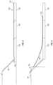
- FIG. 4is a side view of a pipe delivery system portion of the horizontal racking and stand building system, according to one or more embodiments.
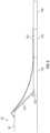
- FIG. 5is another side view with a triple stand of pipe advanced toward the drill floor, according to one or more embodiments.
- FIG. 6is another side view with the triple stand of pipe advanced further toward the drill floor, according to one or more embodiments.
- FIG. 8is a plan view of another horizontal racking and stand building system for use in conjunction with a drill rig such as that of FIG. 1 , according to one or more embodiments.
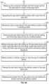
- FIG. 9 Ais a partial flowchart depicting one or more portions of a method of operation of the racking and stand building system, according to one or more embodiments.
- FIG. 9 Bis a partial flowchart depicting one or more portions of a method of operation of the racking and stand building system, according to one or more embodiments.
- FIG. 10is a plan view of another horizontal racking and stand building system for use in conjunction with a drill rig such as that of FIG. 1 , according to one or more embodiments.
- FIG. 11is a plan view of another horizontal racking and stand building system for use in conjunction with a drill rig such as that of FIG. 1 , according to one or more embodiments.
- FIG. 12is a top view of the pipe transfer device of FIG. 3 , according to one or more embodiments.
- FIG. 13is a side view of the pipe transfer device of FIG. 3 , according to one or more embodiments.
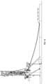
- FIG. 14is a side view with a triple stand of pipe advanced toward the drill floor, according to one or more embodiments.
- FIG. 15is another side view with a triple stand of pipe advanced toward the drill floor, according to one or more embodiments.
- FIG. 16is a side view with a single stand of pipe advanced toward the drill floor, according to one or more embodiments.
- the present disclosurein one or more embodiments, relates to a horizontal racking and pipe stand building system.
- the systemmay include devices and systems for horizontally storing, handling, building, and delivering pipe or pipe stands that may be used in a drill string of a drill rig.
- the systemmay have areas for horizontally storing singles, doubles (e.g., two-pipe stand), triples (e.g., three-pipe stand), or other length pipe stands.
- the systemmay also include a horizontal stand building system for making up pipe stands and immediately passing them to a delivery system or staging them for later delivery (e.g., racking).
- the delivery systemmay be adapted to receive horizontally arranged singles, doubles, triples, or other pipe stand lengths and deliver the pipe or pipe stands to the drill floor.
- the systemmay, thus, allow for safe storage and offline stand building and may free up space on the drill floor for other activities or allow for a smaller drill floor due to the racking and stand building being off of the drill floor. Still further, and since the setback area is not present on the rig, the rig associated with this racking system can be configured as a singles, doubles, or triples rig by the addition or removal of mast sections. For example, the rig may be reconfigured between rig moves or between drilling jobs.
- FIG. 1shows a drill rig 50 having a mast 52 , a drill floor 54 , and a support structure 56 .
- the drill rig 50may be supplemented with a pipe delivery system 58 that may deliver pipe, one-by-one, from a storage location, and to the drill floor.
- the rig 50may alternatively be supplemented with a horizontal racking and stand building system 100 capable of building and storing singles, doubles, or triples, for example, and delivering the same to the drill floor 54 .
- FIG. 2shows a plan view of a horizontal racking and stand building system 100 , according to one or more embodiments.
- the systemmay be adapted for storing single lengths of pipe, building and storing pipe stands, and delivering pipe and/or pipe stands to a drill rig for drilling operations.
- the systemmay also include devices and systems for handling the pipe and/or pipe stands between, or during operations in, the storage, building, and delivery systems.
- the horizontal racking and stand building system 100may include a pipe rack 102 , one or more handling systems 104 , a stand building system 106 , a delivery system 108 , and a pipe stand rack 110 . Each of these elements is described in more detail below.
- a pipe rack 102may be provided.
- the pipe rack 102may be arranged relatively close to the drill rig 50 and may be configured for storing and/or transporting single lengths of drill pipe, drill collar, and/or casing.
- the horizontal racking and stand building system 100may have a first or inboard end defined by the ramp end of the delivery system 108 and a second or outboard end opposite the first end.
- the first endmay be adapted for arrangement adjacent a drill rig, for example, such that the ramp of the delivery system may deliver tubulars to the drill floor.
- the pipe rack 102may be arranged at the first or inboard end of the system.
- thismay be advantageous for making single tubulars readily accessible to the drill rig.
- This layoutmay also result in building pipe stands by adding pipe to an inboard end of the pipe and then translating them outward away from the rig to add additional pipes.
- drill pipe, drill collar, and/or casingmay range in length from 10 feet to 90 feet, or from 20 feet to 40 feet, or from 25 feet to 35 feet.
- tubularmay be approximately 30 feet.
- the pipe rack 102may have length of approximately 30 feet or a length slightly shorter may be used such that supporting members of the rack are arranged within the tubular body allowing the box end and the pin end to hand off the end of the rack 102 , for example.
- the rack 102may include generally horizontal supporting members 112 that may be cantilevered off of vertical supporting posts 114 positioned on one side of the pipe rack 102 .
- the pipe rackmay include shelves for creating layers of piping.
- the shelvesmay be formed from several spaced apart horizontal supporting members 112 .
- the supporting members 112may be arranged generally transverse to the longitudinal axis of the tubulars so as to provide intermittent support along the length of the tubular.
- the supporting membersmay have a first end and a second and may be supported by a post 114 or frame at one of the first and second end forming a cantilevered support for the tubulars.
- a series of shelvesmay be provided in this manner such that tubulars may be selectively rolled or slid off of the shelves onto transfer rails, for example.
- the supports of the rackmay be tipped upward to secure the pipes or other tubulars in the rack and may be tipped downward to release pipes from the rack.
- the pipe rackmay be configured as a trailer having a frame and axles supporting the rack. In this manner, empty racks may be readily changed out with full racks to continue supplying pipe to the operation.
- the systemmay include one or more handling systems 104 for managing the movement of tubulars between the several systems and/or during operations in the several systems.
- one such handling device 104may include a rail system extending from the pipe rack 102 to the stand building system 106 , an additional rail system extending from the stand building 106 system to the delivery system 108 , and still another rail system from the delivery system 108 to the pipe stand rack 110 .
- the several rail systemsmay be continuous rail systems with catches for stopping the movement of tubulars at a respective system along the rail.
- the rail systemmay include two or more rails 116 extending generally transverse to the longitudinal axes of the tubulars.
- the railsmay be supported on upright supports or frames and may be in the form of generally continuous members or several spliced together members.
- the railmay include a substantially flat top surface allowing for rolling support of the tubulars.
- the railmay be, for example, a pipe, tube, angle, or other structural shape, for example.
- the rail systemsmay include conveying systems for sliding or otherwise moving the pipe or pipe stands laterally along the rails.
- the railsmay be equipped with rollers that may be passive or active rollers for moving the pipe along the rails.
- a belt arranged adjacent to the railmay include cleats or other protrusions that extend upward adjacent the rail and above the rail to engage the side of the pipe or other tubular. The rotation of the belt may move the cleat causing the cleat to push on the pipe or other tubular and displace it along the rail.
- the railmay be sloped and movement of the tubular along the rail may be caused by gravity.
- the handling systemsmay be supported on adjustable height supports and the rails of the system may overlap with other aspects of the racking and pipe stand building system.
- the rail systemmay carry a pipe or pipe stand into an area of another operation, stop the pipe or pipe stand from continued lateral displacement, and lower the pipe onto the respective system for further steps.
- the handling systemmay be adapted to hand the pipe or pipe stand off to another handling system when, for example, bypassing a particular aspect of the racking and stand building system.
- the stand building system 106may be arranged generally between the pipe rack 102 and the delivery system 108 . As such, the system may be positioned to receive pipes from the pipe rack 102 , construct pipe stands, and pass the pipe stands on to the delivery system 108 or to the pipe stand rack 110 situated on the other side of the delivery system 108 .
- the stand building system 106may be a horizontally arranged system of supports and devices configured for connecting tubulars end-to-end to create pipe stands.
- the pipe standsmay be two or three singles connected end-to-end to form doubles or triples, respectively. Still other numbers of singles may be connected end-to-end to form pipe stands.
- the stand building system 106may include one or more driving devices 118 and one or more guiding devices 120 .
- the driving devices 118may be configured to drive tubulars along their longitudinal axis.
- the guiding devices 120may be configured for maintaining the lateral position of the tubulars as they move longitudinally or as they rotate. As shown in FIG. 3 and again in FIGS. 12 and 13 , in one or more embodiments, these driving and guiding devices may be provided in conjunction with one another. Alternatively, these devices may be provided in isolation from one another along an axis where pipe stands are to be built.
- providing these devices in conjunction with one anothermay involve providing them on a shared platform or foundation, for example.
- the devicesmay be included on a shared trailer, for example.
- the platform, foundation, or trailermay include a base 122 adapted for placement on the ground or other supporting surface.
- a trailermay be provided.
- a steel skid, frame, or other steel structure, or concrete base 122may be provided.
- the base 122may be sized to accommodate one or more driving or guiding devices.
- the driving devices 118may be active devices configured to drive tubulars along their longitudinal axis, for example.
- the driving devices 118may include a stand portion 124 and an engagement portion 126 .
- the stand portion 124may be secured to the base 122 and may be adapted to hold the tubulars at a selected height.
- the stand portion 124may be adjustable to raise and lower the engagement portion 126 .
- the stand portion 124may include a hydraulic lift, a screw-based lift, or another actuatable device 128 for articulating to extend or retract.
- the engagement portion 126may be adapted to engage the pipe or other tubular and may also be adapted to move the tubular along its longitudinal axis.
- the engagement portion 126may include a wheel, belt, shaker plate, pulley, or other driven element 130 for engaging and advancing the tubular.
- the driven element 130may have an electric motor, for example, in electrical communication with a power source such as a generator or other electric power source, for example.
- the driven element 130may include a v-roller having two conical sides each tapering toward a center of the roller and forming a V-shape when viewed across the rolling axis of the roller. The V-shape may assist to maintain the lateral position of the tubular as the tubular is translated along its longitudinal axis.
- the guiding device 120may be a passive device configured to hold the tubulars and allow the tubulars to rotate about their longitudinal axis.
- the guiding devices 120may be stationary devices and may include a column 132 secured to the base 122 and extending upward to a pair of opposing u-shaped or v-shaped brackets 134 .
- the brackets 134may be substantially rigidly supported by the column 132 and may be spaced apart from one another along the longitudinal axis of the tubular with passive rollers 136 extending therebetween. That is, one or more rollers 136 may be arranged with their rolling or longitudinal axis parallel to the tubular so as to support the weight of the tubular and roll with the tubular as the tubular is rotated.
- the guiding devices 120may be stationary, fixed height devices. Alternatively, the guiding devices 120 may be adjustable in height like the driving devices 118 .
- the stand building system 106may include an iron roughneck, bucking unit, or other pipe or tubular coupling device 138 .
- the tubular or pipe coupling device 138may include adjacent jaws or wrenches arranged in a generally vertical plane with their jaw openings facing the pipe delivery system, for example.
- the jawsmay be adjacent in a direction parallel to the longitudinal axis of the tubulars.
- the jawsmay be stationary laterally and longitudinally relative to the longitudinal axis of the stand building system 106 or they may be articulable laterally relative to the longitudinal axis of the tubulars so as to engage the tubulars and disengage the tubulars laterally or from the side.
- the pipe coupling device 138may be configured to spin a tubular relative to another tubular to advance a threaded pin end of one tubular into a threaded box end of another tubular.
- the device 138may also be configured to torque the joint to provide sufficient tightness to the joint to maintain a secure connection between pipes or tubulars within a pipe stand.
- the pipe coupling device 138may be adapted to break pipe connections in the opposite manner by providing sufficient torque to a pipe joint to release one pipe from another and then unspin the pin end from the box end.
- the stand building system 106may include a plurality of driving units outboard 118 from the pipe coupling device.
- the driving units 118may be spaced apart by a distance slightly less than half the length of a tubular or another selected spacing. In one or more embodiments, the spacing may be selected such that three driving units may be supporting each pipe of a pipe stand, for example.
- the stand building system 106 and/or the entire racking/stand building systemmay include an operator station 140 .
- the operator station 140may include a console for a user to control operations of the racking and/or stand building system 100 . That is, the console may include a computer interface and/or controls for controlling the release of singles from the pipe rack 102 .
- the consolemay include controls for operating the stand building system 106 to shift pipes longitudinally, connect them end to end, and to eject them to the delivery system 108 and/or across the delivery system 108 to the pipe stand rack 110 . Still other operations may be provided to perform the various methods of operation described in more detail below.
- the delivery system 108may receive a single pipe from the pipe rack 102 and handling system 104 and the pusher 152 may be used to push the single pipe up the ramp 142 such that a leading end of the pipe extends through a v-door 60 , for example and reaches a retrieval position above the drill floor 54 .
- the pipe or pipe standmay be positioned on and/or picked up by a handling system to deliver the pipe to the pipe delivery system.
- the driving devices of the pipe stand building systemmay be lowered and/or the rail system may be raised to rest the pipe stand on a plurality of rails.
- the pipe standmay be fed by gravity or active means to deliver the pipe stand to the delivery system. It should be appreciated that once the pipe stand exits the pipe stand building system, additional pipes may be fed to the pipe stand building system to begin constructing an additional pipe stand.
- the pusher on the second extensionmay be used to advance the pipe stand toward the drill rig.
- the leading end of the pipe stande.g., the box end of the third pipe that created the stand
- the pipe standmay flex as this is occurring as shown in FIGS. 5 and 6 , for example.
- the pushermay continue to push the pipe stand toward the rig until the leading end of the pipe stand extends through the v-door on the drill floor and to a retrieval position, To get the pipe stand to this position, the pusher may advance along substantially the full length of the second extension and a portion of the first extension.
- the retrieval position of the leading end of the pipemay be a position relatively close to well center and/or within reach of the top drive elevators.
- the drill rigmay include a dual activity top drive such as the one described in U.S. Provisional Patent Application No. 62/809,093, filed on Feb. 22, 2019, and entitled Dual Activity Top Drive, the content of which is hereby incorporated by reference herein in its entirety.
- the pushermay hold the pipe stand in place until the top drive elevators or other pipe handling device on the drill rig may retrieve the pipe stand. ( 326 ) Once retrieved or once grasped by the drill rig pipe handling system, the pusher may retract to clear the way for additional stands. ( 328 )
- the pipe or pipe standmay be passed beyond the delivery system to the pipe stand rack, ( 330 )
- the handling system between the delivery system and the pipe stand rackmay receive the pipe stand from the handling system between the pipe stand building system and the delivery system and the two systems may bypass the delivery system.
- the pipe or pipe standmay travel by gravity and/or an active means to move the pipe stand laterally to the pipe stand rack.
- the handling systemmay pass the pipe stand to the rack by having the ends of its rails at a same or similar elevation as the support members of the pipe stand rack.
- the rails of the handling systemmay be adjusted upward and/or downward to align with a respective shelf of the pipe stand rack. Stops or catches may be actuated to control the speed of the moving pipe stand and controllably deliver the pipe stand to the pipe stand rack.
- a flowchart or block diagrammay illustrate a method as comprising sequential steps or a process as having a particular order of operations, many of the steps or operations in the flowchart(s) or block diagram(s) illustrated herein can be performed in parallel or concurrently, and the flowchart(s) or block diagram(s) should be read in the context of the various embodiments of the present disclosure.
- the order of the method steps or process operations illustrated in a flowchart or block diagrammay be rearranged for some embodiments.
- a method or process illustrated in a flow chart or block diagramcould have additional steps or operations not included therein or fewer steps or operations than those shown.
- a method stepmay correspond to a method, a function, a procedure, a subroutine, a subprogram, etc.
- FIG. 10is a plan view of another racking and stand building system 300 , according to one or more embodiments. This embodiment may be most similar to the embodiment shown in FIG. 8 . However, the pipe rack 302 may be positioned closer to the rig. As shown, the system 300 may include driving devices 318 , a rail system 304 , a pipe coupling device 338 , a pipe cat 308 , a pusher 352 , a pipe building system 306 , and a control system 354 .
- FIG. 11is a plan view of another racking and stand building system 400 , according to one or more embodiments. This embodiment may be most similar to the embodiment discussed with respect to FIGS. 1 - 7 . As shown, the system may include pipe driving devices 418 , pipe guiding devices 420 , a controller 440 , a pipe coupling device 438 , and a pipe pusher 452 .
- FIGS. 14 - 16are additional views of the pushing system delivering pipes stands to the drill rig using any one of the embodiments described herein.
- the terms “substantially” or “generally”refer to the complete or nearly complete extent or degree of an action, characteristic, property, state, structure, item, or result.
- an object that is “substantially” or “generally” enclosedwould mean that the object is either completely enclosed or nearly completely enclosed.
- the exact allowable degree of deviation from absolute completenessmay in some cases depend on the specific context. However, generally speaking, the nearness of completion will be so as to have generally the same overall result as if absolute and total completion were obtained.
- the use of “substantially” or “generally”is equally applicable when used in a negative connotation to refer to the complete or near complete lack of an action, characteristic, property, state, structure, item, or result.
- an element, combination, embodiment, or composition that is “substantially free of” or “generally free of” an elementmay still actually contain such element as long as there is generally no significant effect thereof.
Landscapes
- Engineering & Computer Science (AREA)
- Life Sciences & Earth Sciences (AREA)
- Geology (AREA)
- Mining & Mineral Resources (AREA)
- Mechanical Engineering (AREA)
- Physics & Mathematics (AREA)
- Environmental & Geological Engineering (AREA)
- Fluid Mechanics (AREA)
- General Life Sciences & Earth Sciences (AREA)
- Geochemistry & Mineralogy (AREA)
- Earth Drilling (AREA)
Abstract
Description
Claims (7)
Priority Applications (1)
| Application Number | Priority Date | Filing Date | Title |
|---|---|---|---|
| US18/005,321US12345105B2 (en) | 2020-07-15 | 2021-06-29 | Horizontal racking and stand building system |
Applications Claiming Priority (3)
| Application Number | Priority Date | Filing Date | Title |
|---|---|---|---|
| US202063052150P | 2020-07-15 | 2020-07-15 | |
| PCT/US2021/070786WO2022016168A1 (en) | 2020-07-15 | 2021-06-29 | Horizontal racking and stand building system |
| US18/005,321US12345105B2 (en) | 2020-07-15 | 2021-06-29 | Horizontal racking and stand building system |
Publications (2)
| Publication Number | Publication Date |
|---|---|
| US20230258046A1 US20230258046A1 (en) | 2023-08-17 |
| US12345105B2true US12345105B2 (en) | 2025-07-01 |
Family
ID=79554307
Family Applications (1)
| Application Number | Title | Priority Date | Filing Date |
|---|---|---|---|
| US18/005,321ActiveUS12345105B2 (en) | 2020-07-15 | 2021-06-29 | Horizontal racking and stand building system |
Country Status (3)
| Country | Link |
|---|---|
| US (1) | US12345105B2 (en) |
| CA (1) | CA3188118A1 (en) |
| WO (1) | WO2022016168A1 (en) |
Families Citing this family (9)
| Publication number | Priority date | Publication date | Assignee | Title |
|---|---|---|---|---|
| US11613940B2 (en) | 2018-08-03 | 2023-03-28 | National Oilwell Varco, L.P. | Devices, systems, and methods for robotic pipe handling |
| WO2020151386A1 (en) | 2019-01-25 | 2020-07-30 | National Oilwell Varco, L.P. | Pipe handling arm |
| US11988059B2 (en) | 2019-02-22 | 2024-05-21 | National Oilwell Varco, L.P. | Dual activity top drive |
| US11834914B2 (en) | 2020-02-10 | 2023-12-05 | National Oilwell Varco, L.P. | Quick coupling drill pipe connector |
| WO2021226622A1 (en) | 2020-05-03 | 2021-11-11 | National Oilwell Varco, L.P. | Passive rotation disconnect |
| CA3188118A1 (en) | 2020-07-15 | 2022-01-20 | National Oilwell Varco, L.P. | Horizontal racking and stand building system |
| US11365592B1 (en) | 2021-02-02 | 2022-06-21 | National Oilwell Varco, L.P. | Robot end-effector orientation constraint for pipe tailing path |
| US11814911B2 (en) | 2021-07-02 | 2023-11-14 | National Oilwell Varco, L.P. | Passive tubular connection guide |
| US11982139B2 (en) | 2021-11-03 | 2024-05-14 | National Oilwell Varco, L.P. | Passive spacer system |
Citations (104)
| Publication number | Priority date | Publication date | Assignee | Title |
|---|---|---|---|---|
| US1818278A (en) | 1930-09-26 | 1931-08-11 | Robert W Siler | Pipe racking device |
| US2531930A (en) | 1947-12-02 | 1950-11-28 | Moore Corp Lee C | Well drilling structure provided with a drill pipe hoist |
| US2615681A (en) | 1950-03-27 | 1952-10-28 | Standard Oil Dev Co | Device for handling pipes |
| US2735556A (en) | 1956-02-21 | stone | ||
| US2885096A (en) | 1954-08-09 | 1959-05-05 | Paul A Medearis | Pipe-handling apparatus for oil wells |
| US2946464A (en) | 1956-07-11 | 1960-07-26 | William C Guier | Apparatus for handling stands of pipe |
| US3225949A (en) | 1962-08-17 | 1965-12-28 | Clark Equipment Co | Lift truck with load handling assembly mounted on a movable frame supported by the steering wheel of the truck |
| US3272365A (en) | 1963-12-03 | 1966-09-13 | Clark Equipment Co | Industrial lift truck |
| US3533516A (en) | 1968-07-26 | 1970-10-13 | William Guier | Guide structure for manipulating drill pipe or the like during drilling of earth bores |
| US3615027A (en) | 1968-11-26 | 1971-10-26 | Byron Jackson Inc | Pipe racking control system |
| US3655071A (en)* | 1970-05-27 | 1972-04-11 | Byron Jackson Inc | Horizontal pipe racking and handling apparatus |
| US3768663A (en) | 1971-10-13 | 1973-10-30 | Byron Jackson Inc | Control for well pipe racks and the like |
| US3921823A (en) | 1970-12-15 | 1975-11-25 | Activite Atom Avance | Movement compensating apparatus for floating drilling |
| US3976207A (en) | 1975-04-07 | 1976-08-24 | Bj-Hughes Inc., Formerly Byron Jackson, Inc. | Casing stabbing apparatus |
| US3994350A (en) | 1975-10-14 | 1976-11-30 | Gardner-Denver Company | Rotary drilling rig |
| US4042123A (en) | 1975-02-06 | 1977-08-16 | Sheldon Loren B | Automated pipe handling system |
| US4117941A (en) | 1976-04-01 | 1978-10-03 | Golar-Nor Offshore A/S | Device for handling and racking riser pipes and drill pipes |
| US4274778A (en) | 1979-06-05 | 1981-06-23 | Putnam Paul S | Mechanized stand handling apparatus for drilling rigs |
| GB2091788A (en) | 1981-01-23 | 1982-08-04 | Varco Int | Top drive wel drilling apparatus |
| US4348920A (en) | 1980-07-31 | 1982-09-14 | Varco International, Inc. | Well pipe connecting and disconnecting apparatus |
| US4397605A (en) | 1979-06-05 | 1983-08-09 | Cowgill Charles F | Mechanized stand handling apparatus for drilling rigs |
| US4531875A (en) | 1982-08-17 | 1985-07-30 | Impro Technologies, Inc. | Automated pipe equipment system |
| US4591006A (en) | 1981-03-26 | 1986-05-27 | Chevron Research Company | Well servicing rig |
| US4621974A (en) | 1982-08-17 | 1986-11-11 | Inpro Technologies, Inc. | Automated pipe equipment system |
| US4680519A (en) | 1985-09-23 | 1987-07-14 | General Electric Co. | Recursive methods for world-to-joint transformation for a robot manipulator |
| US4715761A (en) | 1985-07-30 | 1987-12-29 | Hughes Tool Company | Universal floor mounted pipe handling machine |
| WO1988000274A2 (en) | 1986-06-24 | 1988-01-14 | Domenico Delasandri | Adjustable mechanism for stabbing and threading a drill pipe safety valve |
| US4738321A (en) | 1985-07-19 | 1988-04-19 | Brissonneau Et Lotz Marine | Process and apparatus for vertical racking of drilling shafts on a drilling tower |
| US5038871A (en) | 1990-06-13 | 1991-08-13 | National-Oilwell | Apparatus for supporting a direct drive drilling unit in a position offset from the centerline of a well |
| US5211251A (en) | 1992-04-16 | 1993-05-18 | Woolslayer Companies, Inc. | Apparatus and method for moving track guided equipment to and from a track |
| US5813286A (en) | 1996-04-04 | 1998-09-29 | Hansen; Henning | Support arm |
| US5921329A (en) | 1996-10-03 | 1999-07-13 | Sundowner Offshore Services, Inc. | Installation and removal of top drive units |
| WO1999058811A1 (en) | 1998-05-12 | 1999-11-18 | Richard Martin | Elevator for supporting an elongate member such as a drill pipe |
| WO2001023701A1 (en) | 1999-09-29 | 2001-04-05 | Global Marine Inc. | Horizontal drill pipe racker and delivery system |
| US6260646B1 (en) | 1999-04-29 | 2001-07-17 | Raul U. Fernandez | Power-assisted pallet truck |
| US20020079105A1 (en)* | 2000-10-04 | 2002-06-27 | Kwik Konnect, L.L.C. | Method of connecting tubular members |
| US6412576B1 (en) | 1999-10-16 | 2002-07-02 | William J. Meiners | Methods and apparatus for subterranean drilling utilizing a top drive |
| US20030159854A1 (en) | 2002-02-22 | 2003-08-28 | Michael Simpson | Tubular transfer system |
| WO2004018829A1 (en) | 2002-08-21 | 2004-03-04 | Maritime Hydraulics As | A drill floor pipe handling device |
| US20040057815A1 (en) | 2002-09-25 | 2004-03-25 | Woolslayer Joseph R. | Automated pipe racking process and apparatus |
| US20050126792A1 (en) | 2003-12-12 | 2005-06-16 | Joe Berry | Method and apparatus for offline standbuilding |
| US20060081379A1 (en) | 2004-10-19 | 2006-04-20 | Fehres Neil E | Pivoting pipe handler for off-line make up of drill pipe joints |
| US20060104747A1 (en) | 2004-09-22 | 2006-05-18 | Zahn Baldwin E | Pipe racking system |
| US20060124316A1 (en) | 1998-08-24 | 2006-06-15 | Weatherford/Lamb, Inc. | Method and apparatus for connecting tubulars using a top drive |
| US20060231344A1 (en) | 2005-04-13 | 2006-10-19 | National-Oilwell, L.P. | Pipe elevator with rotating door |
| US20060249292A1 (en) | 2005-05-06 | 2006-11-09 | Guidry Mark L | Casing running tool and method of using same |
| US20070062705A1 (en) | 2005-09-20 | 2007-03-22 | Mike Schats | Wellbore rig elevator systems |
| EP1953334A2 (en) | 2007-01-08 | 2008-08-06 | National-Oilwell Varco, L.P. | A pipe handling system and method |
| US20080238095A1 (en) | 2007-03-28 | 2008-10-02 | Yater Ronald W | Clamp apparatus for threadedly connected tubulars |
| US20080296065A1 (en) | 2005-10-12 | 2008-12-04 | Trond Standal | Drill Floor Device |
| US20090283324A1 (en) | 2008-05-15 | 2009-11-19 | Kameron Wayne Konduc | Mobile drilling rig |
| US7726929B1 (en) | 2007-10-24 | 2010-06-01 | T&T Engineering Services | Pipe handling boom pretensioning apparatus |
| US20100163247A1 (en)* | 2008-12-30 | 2010-07-01 | Monte Neil Wright | Horizontal offline stand building system |
| US20100193198A1 (en) | 2007-04-13 | 2010-08-05 | Richard Lee Murray | Tubular Running Tool and Methods of Use |
| US20100303586A1 (en) | 2009-06-01 | 2010-12-02 | John Benjamin Hankins | Pipe stand transfer systems and methods |
| US20110030942A1 (en)* | 2009-08-04 | 2011-02-10 | T&T Engineering Services, Inc. | Pipe stand |
| US7905311B2 (en) | 2003-05-30 | 2011-03-15 | Translift Bendi Limited | Fork lift truck with a single front wheel |
| US7984757B1 (en) | 2010-08-23 | 2011-07-26 | Larry G. Keast | Drilling rig with a top drive with an air lift thread compensator and a hollow cylinder rod providing minimum flexing of conduit |
| US20110226485A1 (en) | 2010-03-11 | 2011-09-22 | National Oilwell Varco, L.P. | Dual ball upper internal blow out preventer valve |
| US20120018222A1 (en) | 2010-07-20 | 2012-01-26 | National Oilwell Varco, Lp | Inflatable Restraint System |
| US8191637B2 (en) | 2005-12-05 | 2012-06-05 | Xtreme Coil Drilling Corp. | Method and apparatus for conducting earth borehole operations |
| US8215887B2 (en) | 2005-06-01 | 2012-07-10 | Canrig Drilling Technology Ltd. | Pipe-handling apparatus and methods |
| US20130075114A1 (en) | 2011-09-22 | 2013-03-28 | National Oilwell Varco, L.P. | Torque reaction device for pipe running tool |
| WO2013082172A1 (en) | 2011-11-28 | 2013-06-06 | T&T Engineering Services, Inc. | Tubular stand building and racking system |
| US20130142607A1 (en) | 2011-09-20 | 2013-06-06 | Steven J. Ditzler | Boom apparatus with sandwiched knuckle body |
| US20140054089A1 (en) | 2011-04-29 | 2014-02-27 | Robotic Drilling Systems As | Auxiliary Arm for Drilling Equipment |
| US20140097027A1 (en) | 2012-10-05 | 2014-04-10 | National Oilwell Varco Llp | Self-locking top drive guide system |
| US20140145408A1 (en) | 2012-11-29 | 2014-05-29 | Red Devil Equipment Co. | Transport cart |
| WO2014179730A1 (en) | 2013-05-03 | 2014-11-06 | Canrig Drilling Technology Ltd. | Mousehole assembly for manipulating tubulars for subterranean operations |
| US20150053424A1 (en) | 2010-08-09 | 2015-02-26 | Weatherford/Lamb, Inc. | Fill up tool |
| US20150232272A1 (en) | 2014-02-20 | 2015-08-20 | Nabors Industries, Inc. | Methods and Systems for Pipe Management on a Drilling Rig |
| US20150275596A1 (en) | 2014-03-27 | 2015-10-01 | Nabors Drilling Canada Limited | Slant Drill Rig Tong Cart |
| NO20151648A1 (en) | 2013-05-20 | 2015-12-01 | Maersk Drilling As | Dual activity off-shore drilling rig |
| CA2855105A1 (en) | 2014-06-25 | 2015-12-25 | Unknown | Scara robotic pipe racking system |
| WO2016024859A1 (en) | 2014-08-12 | 2016-02-18 | Ihc Holland Ie B.V. | Offshore pipe handling system |
| US20160060979A1 (en) | 2014-08-27 | 2016-03-03 | Nabors Industries, Inc. | Laterally moving racker device on a drilling rig |
| US9291010B1 (en) | 2012-01-17 | 2016-03-22 | Canyon Oak Energy LLC | System for operating a drilling rig with a retracting guide dolly and a top drive |
| US20160115745A1 (en) | 2013-03-12 | 2016-04-28 | Neal O. Bisel | Rod elevator |
| GB2532267A (en) | 2014-11-14 | 2016-05-18 | Nat Oilwell Varco Norway As | A method for placing and removing pipe from a finger rack |
| US20160145954A1 (en) | 2014-11-26 | 2016-05-26 | Weatherford Technology Holdings, Llc | Modular top drive |
| US20160160586A1 (en) | 2014-12-08 | 2016-06-09 | National Oilwell Varco, L.P. | Floor mounted racking arm for handling drill pipe |
| WO2016197255A1 (en) | 2015-06-10 | 2016-12-15 | Warrior Energy Technologies Limited | High efficiency drilling and tripping system |
| WO2017039996A1 (en) | 2015-09-03 | 2017-03-09 | National Oilwell Varco, L.P. | Pipe stand transfer system |
| WO2017087595A1 (en) | 2015-11-17 | 2017-05-26 | Schlumberger Technology Corporation | High trip rate drilling rig |
| US20170172295A1 (en) | 2015-12-22 | 2017-06-22 | LDR Global Industries, LLC | Pipe rack system |
| US20170204687A1 (en)* | 2012-11-19 | 2017-07-20 | Key Energy Services, Llc | Methods of mechanized and automated tripping of rods and tubulars |
| WO2017190120A1 (en) | 2016-04-29 | 2017-11-02 | Schlumberger Technology Corporation | High trip rate drilling rig |
| WO2017193204A1 (en) | 2016-05-12 | 2017-11-16 | Dreco Energy Services Ulc | System and method for offline standbuilding |
| CN108266139A (en) | 2018-01-29 | 2018-07-10 | 扬州华能石化机械有限公司 | The automatic pipe tool top righting method and apparatus in oil field |
| US20180328125A1 (en)* | 2015-06-24 | 2018-11-15 | Coax Technology Inc. | System and method for delivering a tubular pipe segment to a drill rig floor |
| US20180334865A1 (en) | 2017-05-16 | 2018-11-22 | National Oilwell Varco, L.P. | Rig-floor pipe lifting machine |
| US20190017334A1 (en)* | 2017-07-14 | 2019-01-17 | Cameron International Corporation | Horizontal offline stand building system and method of its use in drilling operations |
| US10384907B2 (en) | 2014-05-20 | 2019-08-20 | Longyear Tm, Inc. | Wireline system and methods of using same |
| US10422192B2 (en) | 2014-07-15 | 2019-09-24 | Warrior Rig Technologies Limited | Pipe handling apparatus and methods |
| WO2019195651A1 (en) | 2018-04-05 | 2019-10-10 | National Oilwell Varco, L.P. | System for handling tubulars on a rig |
| US20190352982A1 (en)* | 2018-05-21 | 2019-11-21 | Schlumberger Technology Corporation | Multi-application catwalk system (macs) |
| WO2020028858A1 (en) | 2018-08-03 | 2020-02-06 | National Oilwell Varco, L.P. | Devices, systems, and methods for top drive clearing |
| CN110792399A (en) | 2018-08-03 | 2020-02-14 | 国民油井华高有限公司 | Hoisting system, robotic manipulator and method for handling tubulars on a drilling rig and tubular handling system and method |
| WO2021109532A1 (en) | 2019-12-02 | 2021-06-10 | 四川宏华石油设备有限公司 | Dual-arm robot for pipe processing, and pipe processing system |
| US20220003054A1 (en) | 2020-07-06 | 2022-01-06 | Canrig Robotic Technologies As | Robotic pipe handler systems |
| WO2022016168A1 (en) | 2020-07-15 | 2022-01-20 | National Oilwell Varco, L.P. | Horizontal racking and stand building system |
| CN114278238A (en) | 2021-12-22 | 2022-04-05 | 中煤科工集团西安研究院有限公司 | Automatic change drilling rod handling equipment |
| US20220226990A1 (en) | 2021-01-19 | 2022-07-21 | Industrial Technology Research Institute | Robotic arm system, control method thereof and computer program product thereof |
| WO2025006349A1 (en) | 2023-06-27 | 2025-01-02 | National Oilwell Varco, L.P. | Robotic system for horizontal pipe handling on a drill rig |
- 2021
- 2021-06-29CACA3188118Apatent/CA3188118A1/enactivePending
- 2021-06-29USUS18/005,321patent/US12345105B2/enactiveActive
- 2021-06-29WOPCT/US2021/070786patent/WO2022016168A1/ennot_activeCeased
Patent Citations (117)
| Publication number | Priority date | Publication date | Assignee | Title |
|---|---|---|---|---|
| US2735556A (en) | 1956-02-21 | stone | ||
| US1818278A (en) | 1930-09-26 | 1931-08-11 | Robert W Siler | Pipe racking device |
| US2531930A (en) | 1947-12-02 | 1950-11-28 | Moore Corp Lee C | Well drilling structure provided with a drill pipe hoist |
| US2615681A (en) | 1950-03-27 | 1952-10-28 | Standard Oil Dev Co | Device for handling pipes |
| US2885096A (en) | 1954-08-09 | 1959-05-05 | Paul A Medearis | Pipe-handling apparatus for oil wells |
| US2946464A (en) | 1956-07-11 | 1960-07-26 | William C Guier | Apparatus for handling stands of pipe |
| US3225949A (en) | 1962-08-17 | 1965-12-28 | Clark Equipment Co | Lift truck with load handling assembly mounted on a movable frame supported by the steering wheel of the truck |
| US3272365A (en) | 1963-12-03 | 1966-09-13 | Clark Equipment Co | Industrial lift truck |
| US3533516A (en) | 1968-07-26 | 1970-10-13 | William Guier | Guide structure for manipulating drill pipe or the like during drilling of earth bores |
| US3615027A (en) | 1968-11-26 | 1971-10-26 | Byron Jackson Inc | Pipe racking control system |
| US3655071A (en)* | 1970-05-27 | 1972-04-11 | Byron Jackson Inc | Horizontal pipe racking and handling apparatus |
| US3921823A (en) | 1970-12-15 | 1975-11-25 | Activite Atom Avance | Movement compensating apparatus for floating drilling |
| US3768663A (en) | 1971-10-13 | 1973-10-30 | Byron Jackson Inc | Control for well pipe racks and the like |
| US4042123A (en) | 1975-02-06 | 1977-08-16 | Sheldon Loren B | Automated pipe handling system |
| US3976207A (en) | 1975-04-07 | 1976-08-24 | Bj-Hughes Inc., Formerly Byron Jackson, Inc. | Casing stabbing apparatus |
| US3994350A (en) | 1975-10-14 | 1976-11-30 | Gardner-Denver Company | Rotary drilling rig |
| US4117941A (en) | 1976-04-01 | 1978-10-03 | Golar-Nor Offshore A/S | Device for handling and racking riser pipes and drill pipes |
| US4274778A (en) | 1979-06-05 | 1981-06-23 | Putnam Paul S | Mechanized stand handling apparatus for drilling rigs |
| US4397605A (en) | 1979-06-05 | 1983-08-09 | Cowgill Charles F | Mechanized stand handling apparatus for drilling rigs |
| US4348920A (en) | 1980-07-31 | 1982-09-14 | Varco International, Inc. | Well pipe connecting and disconnecting apparatus |
| GB2091788A (en) | 1981-01-23 | 1982-08-04 | Varco Int | Top drive wel drilling apparatus |
| US4591006A (en) | 1981-03-26 | 1986-05-27 | Chevron Research Company | Well servicing rig |
| US4531875A (en) | 1982-08-17 | 1985-07-30 | Impro Technologies, Inc. | Automated pipe equipment system |
| US4621974A (en) | 1982-08-17 | 1986-11-11 | Inpro Technologies, Inc. | Automated pipe equipment system |
| US4738321A (en) | 1985-07-19 | 1988-04-19 | Brissonneau Et Lotz Marine | Process and apparatus for vertical racking of drilling shafts on a drilling tower |
| US4715761A (en) | 1985-07-30 | 1987-12-29 | Hughes Tool Company | Universal floor mounted pipe handling machine |
| US4680519A (en) | 1985-09-23 | 1987-07-14 | General Electric Co. | Recursive methods for world-to-joint transformation for a robot manipulator |
| WO1988000274A2 (en) | 1986-06-24 | 1988-01-14 | Domenico Delasandri | Adjustable mechanism for stabbing and threading a drill pipe safety valve |
| US5038871A (en) | 1990-06-13 | 1991-08-13 | National-Oilwell | Apparatus for supporting a direct drive drilling unit in a position offset from the centerline of a well |
| US5211251A (en) | 1992-04-16 | 1993-05-18 | Woolslayer Companies, Inc. | Apparatus and method for moving track guided equipment to and from a track |
| US5813286A (en) | 1996-04-04 | 1998-09-29 | Hansen; Henning | Support arm |
| US5921329A (en) | 1996-10-03 | 1999-07-13 | Sundowner Offshore Services, Inc. | Installation and removal of top drive units |
| WO1999058811A1 (en) | 1998-05-12 | 1999-11-18 | Richard Martin | Elevator for supporting an elongate member such as a drill pipe |
| US20060124316A1 (en) | 1998-08-24 | 2006-06-15 | Weatherford/Lamb, Inc. | Method and apparatus for connecting tubulars using a top drive |
| US6260646B1 (en) | 1999-04-29 | 2001-07-17 | Raul U. Fernandez | Power-assisted pallet truck |
| WO2001023701A1 (en) | 1999-09-29 | 2001-04-05 | Global Marine Inc. | Horizontal drill pipe racker and delivery system |
| US6412576B1 (en) | 1999-10-16 | 2002-07-02 | William J. Meiners | Methods and apparatus for subterranean drilling utilizing a top drive |
| US20020079105A1 (en)* | 2000-10-04 | 2002-06-27 | Kwik Konnect, L.L.C. | Method of connecting tubular members |
| US20030159854A1 (en) | 2002-02-22 | 2003-08-28 | Michael Simpson | Tubular transfer system |
| WO2004018829A1 (en) | 2002-08-21 | 2004-03-04 | Maritime Hydraulics As | A drill floor pipe handling device |
| US20040057815A1 (en) | 2002-09-25 | 2004-03-25 | Woolslayer Joseph R. | Automated pipe racking process and apparatus |
| US7905311B2 (en) | 2003-05-30 | 2011-03-15 | Translift Bendi Limited | Fork lift truck with a single front wheel |
| US20050126792A1 (en) | 2003-12-12 | 2005-06-16 | Joe Berry | Method and apparatus for offline standbuilding |
| US20060104747A1 (en) | 2004-09-22 | 2006-05-18 | Zahn Baldwin E | Pipe racking system |
| US20060081379A1 (en) | 2004-10-19 | 2006-04-20 | Fehres Neil E | Pivoting pipe handler for off-line make up of drill pipe joints |
| US20060231344A1 (en) | 2005-04-13 | 2006-10-19 | National-Oilwell, L.P. | Pipe elevator with rotating door |
| US20060249292A1 (en) | 2005-05-06 | 2006-11-09 | Guidry Mark L | Casing running tool and method of using same |
| US8215887B2 (en) | 2005-06-01 | 2012-07-10 | Canrig Drilling Technology Ltd. | Pipe-handling apparatus and methods |
| US20070062705A1 (en) | 2005-09-20 | 2007-03-22 | Mike Schats | Wellbore rig elevator systems |
| US20080296065A1 (en) | 2005-10-12 | 2008-12-04 | Trond Standal | Drill Floor Device |
| US8191637B2 (en) | 2005-12-05 | 2012-06-05 | Xtreme Coil Drilling Corp. | Method and apparatus for conducting earth borehole operations |
| EP1953334A2 (en) | 2007-01-08 | 2008-08-06 | National-Oilwell Varco, L.P. | A pipe handling system and method |
| US8550761B2 (en) | 2007-01-08 | 2013-10-08 | National Oilwell Varco, L.P. | Drill pipe handling and moving system |
| US20110079434A1 (en) | 2007-01-08 | 2011-04-07 | National Oilwell Varco, L.P. | Drill pipe handling and moving system |
| US20080238095A1 (en) | 2007-03-28 | 2008-10-02 | Yater Ronald W | Clamp apparatus for threadedly connected tubulars |
| US20100193198A1 (en) | 2007-04-13 | 2010-08-05 | Richard Lee Murray | Tubular Running Tool and Methods of Use |
| US7726929B1 (en) | 2007-10-24 | 2010-06-01 | T&T Engineering Services | Pipe handling boom pretensioning apparatus |
| US20090283324A1 (en) | 2008-05-15 | 2009-11-19 | Kameron Wayne Konduc | Mobile drilling rig |
| US7992646B2 (en) | 2008-12-30 | 2011-08-09 | Weatherford Canada Partnership | Horizontal offline stand building system |
| US20100163247A1 (en)* | 2008-12-30 | 2010-07-01 | Monte Neil Wright | Horizontal offline stand building system |
| US20100303586A1 (en) | 2009-06-01 | 2010-12-02 | John Benjamin Hankins | Pipe stand transfer systems and methods |
| US20110030942A1 (en)* | 2009-08-04 | 2011-02-10 | T&T Engineering Services, Inc. | Pipe stand |
| US20110226485A1 (en) | 2010-03-11 | 2011-09-22 | National Oilwell Varco, L.P. | Dual ball upper internal blow out preventer valve |
| US20120018222A1 (en) | 2010-07-20 | 2012-01-26 | National Oilwell Varco, Lp | Inflatable Restraint System |
| US20150053424A1 (en) | 2010-08-09 | 2015-02-26 | Weatherford/Lamb, Inc. | Fill up tool |
| US7984757B1 (en) | 2010-08-23 | 2011-07-26 | Larry G. Keast | Drilling rig with a top drive with an air lift thread compensator and a hollow cylinder rod providing minimum flexing of conduit |
| US20140054089A1 (en) | 2011-04-29 | 2014-02-27 | Robotic Drilling Systems As | Auxiliary Arm for Drilling Equipment |
| US20130142607A1 (en) | 2011-09-20 | 2013-06-06 | Steven J. Ditzler | Boom apparatus with sandwiched knuckle body |
| US20130075114A1 (en) | 2011-09-22 | 2013-03-28 | National Oilwell Varco, L.P. | Torque reaction device for pipe running tool |
| WO2013082172A1 (en) | 2011-11-28 | 2013-06-06 | T&T Engineering Services, Inc. | Tubular stand building and racking system |
| US9291010B1 (en) | 2012-01-17 | 2016-03-22 | Canyon Oak Energy LLC | System for operating a drilling rig with a retracting guide dolly and a top drive |
| US20140097027A1 (en) | 2012-10-05 | 2014-04-10 | National Oilwell Varco Llp | Self-locking top drive guide system |
| US20170204687A1 (en)* | 2012-11-19 | 2017-07-20 | Key Energy Services, Llc | Methods of mechanized and automated tripping of rods and tubulars |
| US20140145408A1 (en) | 2012-11-29 | 2014-05-29 | Red Devil Equipment Co. | Transport cart |
| US20160115745A1 (en) | 2013-03-12 | 2016-04-28 | Neal O. Bisel | Rod elevator |
| CA2911388A1 (en) | 2013-05-03 | 2014-11-06 | Canrig Drilling Technology Ltd. | Mousehole assembly for manipulating tubulars for subterranean operations |
| WO2014179730A1 (en) | 2013-05-03 | 2014-11-06 | Canrig Drilling Technology Ltd. | Mousehole assembly for manipulating tubulars for subterranean operations |
| NO20151648A1 (en) | 2013-05-20 | 2015-12-01 | Maersk Drilling As | Dual activity off-shore drilling rig |
| US20150232272A1 (en) | 2014-02-20 | 2015-08-20 | Nabors Industries, Inc. | Methods and Systems for Pipe Management on a Drilling Rig |
| US20150275596A1 (en) | 2014-03-27 | 2015-10-01 | Nabors Drilling Canada Limited | Slant Drill Rig Tong Cart |
| US10384907B2 (en) | 2014-05-20 | 2019-08-20 | Longyear Tm, Inc. | Wireline system and methods of using same |
| CA2855105A1 (en) | 2014-06-25 | 2015-12-25 | Unknown | Scara robotic pipe racking system |
| US10422192B2 (en) | 2014-07-15 | 2019-09-24 | Warrior Rig Technologies Limited | Pipe handling apparatus and methods |
| WO2016024859A1 (en) | 2014-08-12 | 2016-02-18 | Ihc Holland Ie B.V. | Offshore pipe handling system |
| US20160060979A1 (en) | 2014-08-27 | 2016-03-03 | Nabors Industries, Inc. | Laterally moving racker device on a drilling rig |
| GB2532267A (en) | 2014-11-14 | 2016-05-18 | Nat Oilwell Varco Norway As | A method for placing and removing pipe from a finger rack |
| US20170306710A1 (en) | 2014-11-14 | 2017-10-26 | National Oilwell Varco Norway As | A method for placing and removing pipe from a finger rack |
| US20160145954A1 (en) | 2014-11-26 | 2016-05-26 | Weatherford Technology Holdings, Llc | Modular top drive |
| US20160160586A1 (en) | 2014-12-08 | 2016-06-09 | National Oilwell Varco, L.P. | Floor mounted racking arm for handling drill pipe |
| WO2016197255A1 (en) | 2015-06-10 | 2016-12-15 | Warrior Energy Technologies Limited | High efficiency drilling and tripping system |
| US20180328125A1 (en)* | 2015-06-24 | 2018-11-15 | Coax Technology Inc. | System and method for delivering a tubular pipe segment to a drill rig floor |
| WO2017039996A1 (en) | 2015-09-03 | 2017-03-09 | National Oilwell Varco, L.P. | Pipe stand transfer system |
| WO2017087595A1 (en) | 2015-11-17 | 2017-05-26 | Schlumberger Technology Corporation | High trip rate drilling rig |
| US20170234088A1 (en) | 2015-11-17 | 2017-08-17 | Schlumberger Technology Corporation | High trip rate drilling rig |
| US20170172295A1 (en) | 2015-12-22 | 2017-06-22 | LDR Global Industries, LLC | Pipe rack system |
| WO2017190120A1 (en) | 2016-04-29 | 2017-11-02 | Schlumberger Technology Corporation | High trip rate drilling rig |
| WO2017193204A1 (en) | 2016-05-12 | 2017-11-16 | Dreco Energy Services Ulc | System and method for offline standbuilding |
| US20190145197A1 (en) | 2016-05-12 | 2019-05-16 | Dreco Energy Services Ulc | System and method for offline standbuilding |
| US20180334865A1 (en) | 2017-05-16 | 2018-11-22 | National Oilwell Varco, L.P. | Rig-floor pipe lifting machine |
| US20190017334A1 (en)* | 2017-07-14 | 2019-01-17 | Cameron International Corporation | Horizontal offline stand building system and method of its use in drilling operations |
| CN108266139A (en) | 2018-01-29 | 2018-07-10 | 扬州华能石化机械有限公司 | The automatic pipe tool top righting method and apparatus in oil field |
| WO2019195651A1 (en) | 2018-04-05 | 2019-10-10 | National Oilwell Varco, L.P. | System for handling tubulars on a rig |
| US20190309585A1 (en) | 2018-04-05 | 2019-10-10 | Travis James Miller | System for handling tubulars on a rig |
| US20190352982A1 (en)* | 2018-05-21 | 2019-11-21 | Schlumberger Technology Corporation | Multi-application catwalk system (macs) |
| WO2020028856A1 (en) | 2018-08-03 | 2020-02-06 | National Oilwell Varco, L.P. | Accelerated tripping system and method |
| WO2020028858A1 (en) | 2018-08-03 | 2020-02-06 | National Oilwell Varco, L.P. | Devices, systems, and methods for top drive clearing |
| WO2020028853A1 (en) | 2018-08-03 | 2020-02-06 | National Oilwell Varco, L.P. | End effectors for automated pipe handling |
| WO2020028852A1 (en) | 2018-08-03 | 2020-02-06 | National Oilwell Varco, L.P. | Devices, systems, and methods for robotic pipe handling |
| US20200040673A1 (en) | 2018-08-03 | 2020-02-06 | National Oilwell Varco, L.P. | Devices, systems, and methods for top drive clearing |
| US20200040674A1 (en) | 2018-08-03 | 2020-02-06 | National Oilwell Varco, L.P. | Devices, systems, and methods for robotic pipe handling |
| CN110792399A (en) | 2018-08-03 | 2020-02-14 | 国民油井华高有限公司 | Hoisting system, robotic manipulator and method for handling tubulars on a drilling rig and tubular handling system and method |
| WO2021109532A1 (en) | 2019-12-02 | 2021-06-10 | 四川宏华石油设备有限公司 | Dual-arm robot for pipe processing, and pipe processing system |
| US20220003054A1 (en) | 2020-07-06 | 2022-01-06 | Canrig Robotic Technologies As | Robotic pipe handler systems |
| WO2022016168A1 (en) | 2020-07-15 | 2022-01-20 | National Oilwell Varco, L.P. | Horizontal racking and stand building system |
| US20220226990A1 (en) | 2021-01-19 | 2022-07-21 | Industrial Technology Research Institute | Robotic arm system, control method thereof and computer program product thereof |
| CN114278238A (en) | 2021-12-22 | 2022-04-05 | 中煤科工集团西安研究院有限公司 | Automatic change drilling rod handling equipment |
| WO2025006349A1 (en) | 2023-06-27 | 2025-01-02 | National Oilwell Varco, L.P. | Robotic system for horizontal pipe handling on a drill rig |
Non-Patent Citations (44)
Also Published As
| Publication number | Publication date |
|---|---|
| CA3188118A1 (en) | 2022-01-20 |
| WO2022016168A1 (en) | 2022-01-20 |
| US20230258046A1 (en) | 2023-08-17 |
Similar Documents
| Publication | Publication Date | Title |
|---|---|---|
| US12345105B2 (en) | Horizontal racking and stand building system | |
| US9157286B2 (en) | Portable pipe handling system | |
| EP1916379B1 (en) | Horizontal pipes handling system | |
| US7992646B2 (en) | Horizontal offline stand building system | |
| EP1246998B1 (en) | Horizontal pipe handling device | |
| US7600584B2 (en) | Pipe handling system with a movable magazine | |
| US8052368B2 (en) | Catwalk for a drilling rig | |
| US8840352B2 (en) | Apparatus and method for handling pipe | |
| US10422192B2 (en) | Pipe handling apparatus and methods | |
| CN112096318B (en) | Pipe conveying system and conveying method | |
| US7537424B2 (en) | Apparatus and method for handling pipe sections | |
| US4129221A (en) | Pipe handling apparatus | |
| US7240742B2 (en) | Pipe handling system with a movable magazine | |
| CN109477362B (en) | Method and apparatus for transporting drill pipe | |
| US9057227B2 (en) | Pipe handling apparatus | |
| BR112015024932B1 (en) | TRIPLE ACTIVITY SYSTEM PROVIDED ON A DRILLING FLOOR ON A DRILLING SHIP AND METHOD FOR CONDUCTING DRILLING OPERATIONS ON A SEA BED UNDER THE DRILLING SHIP | |
| KR20150081281A (en) | Cantilever contained drilling unit | |
| CN114382426A (en) | Well drilling and repairing machine and continuous tripping method thereof | |
| CA2648400C (en) | Horizontal offline stand building system |
Legal Events
| Date | Code | Title | Description |
|---|---|---|---|
| FEPP | Fee payment procedure | Free format text:ENTITY STATUS SET TO UNDISCOUNTED (ORIGINAL EVENT CODE: BIG.); ENTITY STATUS OF PATENT OWNER: LARGE ENTITY | |
| AS | Assignment | Owner name:NATIONAL OILWELL VARCO, L.P., TEXAS Free format text:ASSIGNMENT OF ASSIGNORS INTEREST;ASSIGNOR:MCKENZIE, ANDREW IAN;REEL/FRAME:063767/0238 Effective date:20210810 | |
| STPP | Information on status: patent application and granting procedure in general | Free format text:DOCKETED NEW CASE - READY FOR EXAMINATION | |
| STPP | Information on status: patent application and granting procedure in general | Free format text:NON FINAL ACTION MAILED | |
| STPP | Information on status: patent application and granting procedure in general | Free format text:NON FINAL ACTION MAILED | |
| STPP | Information on status: patent application and granting procedure in general | Free format text:NON FINAL ACTION MAILED | |
| STPP | Information on status: patent application and granting procedure in general | Free format text:RESPONSE TO NON-FINAL OFFICE ACTION ENTERED AND FORWARDED TO EXAMINER | |
| STPP | Information on status: patent application and granting procedure in general | Free format text:FINAL REJECTION MAILED | |
| STPP | Information on status: patent application and granting procedure in general | Free format text:RESPONSE AFTER FINAL ACTION FORWARDED TO EXAMINER | |
| STPP | Information on status: patent application and granting procedure in general | Free format text:ADVISORY ACTION MAILED | |
| STPP | Information on status: patent application and granting procedure in general | Free format text:DOCKETED NEW CASE - READY FOR EXAMINATION | |
| STCF | Information on status: patent grant | Free format text:PATENTED CASE |