US12345057B2 - Automated drywall painting system and method - Google Patents
Automated drywall painting system and methodDownload PDFInfo
- Publication number
- US12345057B2 US12345057B2US17/968,372US202217968372AUS12345057B2US 12345057 B2US12345057 B2US 12345057B2US 202217968372 AUS202217968372 AUS 202217968372AUS 12345057 B2US12345057 B2US 12345057B2
- Authority
- US
- United States
- Prior art keywords
- paint
- painting
- end effector
- wall assembly
- painting system
- Prior art date
- Legal status (The legal status is an assumption and is not a legal conclusion. Google has not performed a legal analysis and makes no representation as to the accuracy of the status listed.)
- Active, expires
Links
Images


Classifications
- E—FIXED CONSTRUCTIONS
- E04—BUILDING
- E04F—FINISHING WORK ON BUILDINGS, e.g. STAIRS, FLOORS
- E04F21/00—Implements for finishing work on buildings
- E04F21/02—Implements for finishing work on buildings for applying plasticised masses to surfaces, e.g. plastering walls
- E04F21/026—Implements for finishing work on buildings for applying plasticised masses to surfaces, e.g. plastering walls for applying adhesive or joint compound to joint tapes, in particular drywall tapes
- B—PERFORMING OPERATIONS; TRANSPORTING
- B05—SPRAYING OR ATOMISING IN GENERAL; APPLYING FLUENT MATERIALS TO SURFACES, IN GENERAL
- B05B—SPRAYING APPARATUS; ATOMISING APPARATUS; NOZZLES
- B05B1/00—Nozzles, spray heads or other outlets, with or without auxiliary devices such as valves, heating means
- B05B1/28—Nozzles, spray heads or other outlets, with or without auxiliary devices such as valves, heating means with integral means for shielding the discharged liquid or other fluent material, e.g. to limit area of spray; with integral means for catching drips or collecting surplus liquid or other fluent material
- B—PERFORMING OPERATIONS; TRANSPORTING
- B05—SPRAYING OR ATOMISING IN GENERAL; APPLYING FLUENT MATERIALS TO SURFACES, IN GENERAL
- B05B—SPRAYING APPARATUS; ATOMISING APPARATUS; NOZZLES
- B05B12/00—Arrangements for controlling delivery; Arrangements for controlling the spray area
- B05B12/08—Arrangements for controlling delivery; Arrangements for controlling the spray area responsive to condition of liquid or other fluent material to be discharged, of ambient medium or of target ; responsive to condition of spray devices or of supply means, e.g. pipes, pumps or their drive means
- B05B12/12—Arrangements for controlling delivery; Arrangements for controlling the spray area responsive to condition of liquid or other fluent material to be discharged, of ambient medium or of target ; responsive to condition of spray devices or of supply means, e.g. pipes, pumps or their drive means responsive to conditions of ambient medium or target, e.g. humidity, temperature position or movement of the target relative to the spray apparatus
- B05B12/122—Arrangements for controlling delivery; Arrangements for controlling the spray area responsive to condition of liquid or other fluent material to be discharged, of ambient medium or of target ; responsive to condition of spray devices or of supply means, e.g. pipes, pumps or their drive means responsive to conditions of ambient medium or target, e.g. humidity, temperature position or movement of the target relative to the spray apparatus responsive to presence or shape of target
- B—PERFORMING OPERATIONS; TRANSPORTING
- B05—SPRAYING OR ATOMISING IN GENERAL; APPLYING FLUENT MATERIALS TO SURFACES, IN GENERAL
- B05B—SPRAYING APPARATUS; ATOMISING APPARATUS; NOZZLES
- B05B13/00—Machines or plants for applying liquids or other fluent materials to surfaces of objects or other work by spraying, not covered by groups B05B1/00 - B05B11/00
- B05B13/02—Means for supporting work; Arrangement or mounting of spray heads; Adaptation or arrangement of means for feeding work
- B05B13/04—Means for supporting work; Arrangement or mounting of spray heads; Adaptation or arrangement of means for feeding work the spray heads being moved during spraying operation
- B05B13/0431—Means for supporting work; Arrangement or mounting of spray heads; Adaptation or arrangement of means for feeding work the spray heads being moved during spraying operation with spray heads moved by robots or articulated arms, e.g. for applying liquid or other fluent material to three-dimensional [3D] surfaces
- B—PERFORMING OPERATIONS; TRANSPORTING
- B05—SPRAYING OR ATOMISING IN GENERAL; APPLYING FLUENT MATERIALS TO SURFACES, IN GENERAL
- B05B—SPRAYING APPARATUS; ATOMISING APPARATUS; NOZZLES
- B05B15/00—Details of spraying plant or spraying apparatus not otherwise provided for; Accessories
- B05B15/60—Arrangements for mounting, supporting or holding spraying apparatus
- B05B15/62—Arrangements for supporting spraying apparatus, e.g. suction cups
- B05B15/625—Arrangements for supporting spraying apparatus, e.g. suction cups designed to be placed on the ground
- B—PERFORMING OPERATIONS; TRANSPORTING
- B05—SPRAYING OR ATOMISING IN GENERAL; APPLYING FLUENT MATERIALS TO SURFACES, IN GENERAL
- B05B—SPRAYING APPARATUS; ATOMISING APPARATUS; NOZZLES
- B05B7/00—Spraying apparatus for discharge of liquids or other fluent materials from two or more sources, e.g. of liquid and air, of powder and gas
- B05B7/0093—At least a part of the apparatus, e.g. a container, being provided with means, e.g. wheels or casters for allowing its displacement relative to the ground
- B—PERFORMING OPERATIONS; TRANSPORTING
- B05—SPRAYING OR ATOMISING IN GENERAL; APPLYING FLUENT MATERIALS TO SURFACES, IN GENERAL
- B05B—SPRAYING APPARATUS; ATOMISING APPARATUS; NOZZLES
- B05B9/00—Spraying apparatus for discharge of liquids or other fluent material, without essentially mixing with gas or vapour
- B05B9/007—At least a part of the apparatus, e.g. a container, being provided with means, e.g. wheels, for allowing its displacement relative to the ground
- B—PERFORMING OPERATIONS; TRANSPORTING
- B05—SPRAYING OR ATOMISING IN GENERAL; APPLYING FLUENT MATERIALS TO SURFACES, IN GENERAL
- B05C—APPARATUS FOR APPLYING FLUENT MATERIALS TO SURFACES, IN GENERAL
- B05C11/00—Component parts, details or accessories not specifically provided for in groups B05C1/00 - B05C9/00
- B05C11/10—Storage, supply or control of liquid or other fluent material; Recovery of excess liquid or other fluent material
- B05C11/1039—Recovery of excess liquid or other fluent material; Controlling means therefor
- B—PERFORMING OPERATIONS; TRANSPORTING
- B05—SPRAYING OR ATOMISING IN GENERAL; APPLYING FLUENT MATERIALS TO SURFACES, IN GENERAL
- B05C—APPARATUS FOR APPLYING FLUENT MATERIALS TO SURFACES, IN GENERAL
- B05C5/00—Apparatus in which liquid or other fluent material is projected, poured or allowed to flow on to the surface of the work
- B05C5/002—Apparatus in which liquid or other fluent material is projected, poured or allowed to flow on to the surface of the work the work consisting of separate articles
- B05C5/004—Apparatus in which liquid or other fluent material is projected, poured or allowed to flow on to the surface of the work the work consisting of separate articles the work consisting of separate rectangular flat articles, e.g. flat sheets
- B—PERFORMING OPERATIONS; TRANSPORTING
- B05—SPRAYING OR ATOMISING IN GENERAL; APPLYING FLUENT MATERIALS TO SURFACES, IN GENERAL
- B05C—APPARATUS FOR APPLYING FLUENT MATERIALS TO SURFACES, IN GENERAL
- B05C5/00—Apparatus in which liquid or other fluent material is projected, poured or allowed to flow on to the surface of the work
- B05C5/02—Apparatus in which liquid or other fluent material is projected, poured or allowed to flow on to the surface of the work the liquid or other fluent material being discharged through an outlet orifice by pressure, e.g. from an outlet device in contact or almost in contact, with the work
- B—PERFORMING OPERATIONS; TRANSPORTING
- B05—SPRAYING OR ATOMISING IN GENERAL; APPLYING FLUENT MATERIALS TO SURFACES, IN GENERAL
- B05D—PROCESSES FOR APPLYING FLUENT MATERIALS TO SURFACES, IN GENERAL
- B05D1/00—Processes for applying liquids or other fluent materials
- B05D1/02—Processes for applying liquids or other fluent materials performed by spraying
- B—PERFORMING OPERATIONS; TRANSPORTING
- B05—SPRAYING OR ATOMISING IN GENERAL; APPLYING FLUENT MATERIALS TO SURFACES, IN GENERAL
- B05D—PROCESSES FOR APPLYING FLUENT MATERIALS TO SURFACES, IN GENERAL
- B05D3/00—Pretreatment of surfaces to which liquids or other fluent materials are to be applied; After-treatment of applied coatings, e.g. intermediate treating of an applied coating preparatory to subsequent applications of liquids or other fluent materials
- B05D3/04—Pretreatment of surfaces to which liquids or other fluent materials are to be applied; After-treatment of applied coatings, e.g. intermediate treating of an applied coating preparatory to subsequent applications of liquids or other fluent materials by exposure to gases
- B05D3/0406—Pretreatment of surfaces to which liquids or other fluent materials are to be applied; After-treatment of applied coatings, e.g. intermediate treating of an applied coating preparatory to subsequent applications of liquids or other fluent materials by exposure to gases the gas being air
- B05D3/0413—Heating with air
- B—PERFORMING OPERATIONS; TRANSPORTING
- B05—SPRAYING OR ATOMISING IN GENERAL; APPLYING FLUENT MATERIALS TO SURFACES, IN GENERAL
- B05D—PROCESSES FOR APPLYING FLUENT MATERIALS TO SURFACES, IN GENERAL
- B05D3/00—Pretreatment of surfaces to which liquids or other fluent materials are to be applied; After-treatment of applied coatings, e.g. intermediate treating of an applied coating preparatory to subsequent applications of liquids or other fluent materials
- B05D3/06—Pretreatment of surfaces to which liquids or other fluent materials are to be applied; After-treatment of applied coatings, e.g. intermediate treating of an applied coating preparatory to subsequent applications of liquids or other fluent materials by exposure to radiation
- B05D3/061—Pretreatment of surfaces to which liquids or other fluent materials are to be applied; After-treatment of applied coatings, e.g. intermediate treating of an applied coating preparatory to subsequent applications of liquids or other fluent materials by exposure to radiation using U.V.
- B05D3/065—After-treatment
- B05D3/067—Curing or cross-linking the coating
- B—PERFORMING OPERATIONS; TRANSPORTING
- B24—GRINDING; POLISHING
- B24B—MACHINES, DEVICES, OR PROCESSES FOR GRINDING OR POLISHING; DRESSING OR CONDITIONING OF ABRADING SURFACES; FEEDING OF GRINDING, POLISHING, OR LAPPING AGENTS
- B24B49/00—Measuring or gauging equipment for controlling the feed movement of the grinding tool or work; Arrangements of indicating or measuring equipment, e.g. for indicating the start of the grinding operation
- B24B49/12—Measuring or gauging equipment for controlling the feed movement of the grinding tool or work; Arrangements of indicating or measuring equipment, e.g. for indicating the start of the grinding operation involving optical means
- B—PERFORMING OPERATIONS; TRANSPORTING
- B24—GRINDING; POLISHING
- B24B—MACHINES, DEVICES, OR PROCESSES FOR GRINDING OR POLISHING; DRESSING OR CONDITIONING OF ABRADING SURFACES; FEEDING OF GRINDING, POLISHING, OR LAPPING AGENTS
- B24B55/00—Safety devices for grinding or polishing machines; Accessories fitted to grinding or polishing machines for keeping tools or parts of the machine in good working condition
- B24B55/06—Dust extraction equipment on grinding or polishing machines
- B24B55/10—Dust extraction equipment on grinding or polishing machines specially designed for portable grinding machines, e.g. hand-guided
- B—PERFORMING OPERATIONS; TRANSPORTING
- B24—GRINDING; POLISHING
- B24B—MACHINES, DEVICES, OR PROCESSES FOR GRINDING OR POLISHING; DRESSING OR CONDITIONING OF ABRADING SURFACES; FEEDING OF GRINDING, POLISHING, OR LAPPING AGENTS
- B24B7/00—Machines or devices designed for grinding plane surfaces on work, including polishing plane glass surfaces; Accessories therefor
- B24B7/10—Single-purpose machines or devices
- B24B7/18—Single-purpose machines or devices for grinding floorings, walls, ceilings or the like
- B24B7/182—Single-purpose machines or devices for grinding floorings, walls, ceilings or the like for walls and ceilings
- B—PERFORMING OPERATIONS; TRANSPORTING
- B25—HAND TOOLS; PORTABLE POWER-DRIVEN TOOLS; MANIPULATORS
- B25J—MANIPULATORS; CHAMBERS PROVIDED WITH MANIPULATION DEVICES
- B25J11/00—Manipulators not otherwise provided for
- B25J11/005—Manipulators for mechanical processing tasks
- B25J11/0055—Cutting
- B—PERFORMING OPERATIONS; TRANSPORTING
- B25—HAND TOOLS; PORTABLE POWER-DRIVEN TOOLS; MANIPULATORS
- B25J—MANIPULATORS; CHAMBERS PROVIDED WITH MANIPULATION DEVICES
- B25J11/00—Manipulators not otherwise provided for
- B25J11/0075—Manipulators for painting or coating
- B—PERFORMING OPERATIONS; TRANSPORTING
- B25—HAND TOOLS; PORTABLE POWER-DRIVEN TOOLS; MANIPULATORS
- B25J—MANIPULATORS; CHAMBERS PROVIDED WITH MANIPULATION DEVICES
- B25J15/00—Gripping heads and other end effectors
- B25J15/0019—End effectors other than grippers
- B—PERFORMING OPERATIONS; TRANSPORTING
- B25—HAND TOOLS; PORTABLE POWER-DRIVEN TOOLS; MANIPULATORS
- B25J—MANIPULATORS; CHAMBERS PROVIDED WITH MANIPULATION DEVICES
- B25J9/00—Programme-controlled manipulators
- B25J9/16—Programme controls
- B25J9/1656—Programme controls characterised by programming, planning systems for manipulators
- B25J9/1661—Programme controls characterised by programming, planning systems for manipulators characterised by task planning, object-oriented languages
- B—PERFORMING OPERATIONS; TRANSPORTING
- B25—HAND TOOLS; PORTABLE POWER-DRIVEN TOOLS; MANIPULATORS
- B25J—MANIPULATORS; CHAMBERS PROVIDED WITH MANIPULATION DEVICES
- B25J9/00—Programme-controlled manipulators
- B25J9/16—Programme controls
- B25J9/1694—Programme controls characterised by use of sensors other than normal servo-feedback from position, speed or acceleration sensors, perception control, multi-sensor controlled systems, sensor fusion
- B25J9/1697—Vision controlled systems
- B—PERFORMING OPERATIONS; TRANSPORTING
- B26—HAND CUTTING TOOLS; CUTTING; SEVERING
- B26D—CUTTING; DETAILS COMMON TO MACHINES FOR PERFORATING, PUNCHING, CUTTING-OUT, STAMPING-OUT OR SEVERING
- B26D5/00—Arrangements for operating and controlling machines or devices for cutting, cutting-out, stamping-out, punching, perforating, or severing by means other than cutting
- B26D5/007—Control means comprising cameras, vision or image processing systems
- E—FIXED CONSTRUCTIONS
- E04—BUILDING
- E04B—GENERAL BUILDING CONSTRUCTIONS; WALLS, e.g. PARTITIONS; ROOFS; FLOORS; CEILINGS; INSULATION OR OTHER PROTECTION OF BUILDINGS
- E04B1/00—Constructions in general; Structures which are not restricted either to walls, e.g. partitions, or floors or ceilings or roofs
- E04B1/62—Insulation or other protection; Elements or use of specified material therefor
- E04B1/74—Heat, sound or noise insulation, absorption, or reflection; Other building methods affording favourable thermal or acoustical conditions, e.g. accumulating of heat within walls
- E04B1/76—Heat, sound or noise insulation, absorption, or reflection; Other building methods affording favourable thermal or acoustical conditions, e.g. accumulating of heat within walls specifically with respect to heat only
- E04B1/7654—Heat, sound or noise insulation, absorption, or reflection; Other building methods affording favourable thermal or acoustical conditions, e.g. accumulating of heat within walls specifically with respect to heat only comprising an insulating layer, disposed between two longitudinal supporting elements, e.g. to insulate ceilings
- E—FIXED CONSTRUCTIONS
- E04—BUILDING
- E04F—FINISHING WORK ON BUILDINGS, e.g. STAIRS, FLOORS
- E04F21/00—Implements for finishing work on buildings
- E04F21/0046—Implements for finishing work on buildings for reshaping butt joints between adjacent panels, e.g. drywall panels
- E—FIXED CONSTRUCTIONS
- E04—BUILDING
- E04F—FINISHING WORK ON BUILDINGS, e.g. STAIRS, FLOORS
- E04F21/00—Implements for finishing work on buildings
- E04F21/02—Implements for finishing work on buildings for applying plasticised masses to surfaces, e.g. plastering walls
- E04F21/06—Implements for applying plaster, insulating material, or the like
- E04F21/08—Mechanical implements
- E04F21/085—Mechanical implements for filling building cavity walls with insulating materials
- E—FIXED CONSTRUCTIONS
- E04—BUILDING
- E04F—FINISHING WORK ON BUILDINGS, e.g. STAIRS, FLOORS
- E04F21/00—Implements for finishing work on buildings
- E04F21/02—Implements for finishing work on buildings for applying plasticised masses to surfaces, e.g. plastering walls
- E04F21/06—Implements for applying plaster, insulating material, or the like
- E04F21/08—Mechanical implements
- E04F21/12—Mechanical implements acting by gas pressure, e.g. steam pressure
- E—FIXED CONSTRUCTIONS
- E04—BUILDING
- E04F—FINISHING WORK ON BUILDINGS, e.g. STAIRS, FLOORS
- E04F21/00—Implements for finishing work on buildings
- E04F21/02—Implements for finishing work on buildings for applying plasticised masses to surfaces, e.g. plastering walls
- E04F21/16—Implements for after-treatment of plaster or the like before it has hardened or dried, e.g. smoothing-tools, profile trowels
- E—FIXED CONSTRUCTIONS
- E04—BUILDING
- E04F—FINISHING WORK ON BUILDINGS, e.g. STAIRS, FLOORS
- E04F21/00—Implements for finishing work on buildings
- E04F21/165—Implements for finishing work on buildings for finishing joints, e.g. implements for raking or filling joints, jointers
- E—FIXED CONSTRUCTIONS
- E04—BUILDING
- E04F—FINISHING WORK ON BUILDINGS, e.g. STAIRS, FLOORS
- E04F21/00—Implements for finishing work on buildings
- E04F21/165—Implements for finishing work on buildings for finishing joints, e.g. implements for raking or filling joints, jointers
- E04F21/1652—Implements for finishing work on buildings for finishing joints, e.g. implements for raking or filling joints, jointers for smoothing and shaping joint compound to a desired contour
- E—FIXED CONSTRUCTIONS
- E04—BUILDING
- E04F—FINISHING WORK ON BUILDINGS, e.g. STAIRS, FLOORS
- E04F21/00—Implements for finishing work on buildings
- E04F21/165—Implements for finishing work on buildings for finishing joints, e.g. implements for raking or filling joints, jointers
- E04F21/1657—Implements for finishing work on buildings for finishing joints, e.g. implements for raking or filling joints, jointers for applying tape to joints, e.g. drywall taper tools
- E—FIXED CONSTRUCTIONS
- E04—BUILDING
- E04F—FINISHING WORK ON BUILDINGS, e.g. STAIRS, FLOORS
- E04F21/00—Implements for finishing work on buildings
- E04F21/18—Implements for finishing work on buildings for setting wall or ceiling slabs or plates
- B—PERFORMING OPERATIONS; TRANSPORTING
- B05—SPRAYING OR ATOMISING IN GENERAL; APPLYING FLUENT MATERIALS TO SURFACES, IN GENERAL
- B05B—SPRAYING APPARATUS; ATOMISING APPARATUS; NOZZLES
- B05B14/00—Arrangements for collecting, re-using or eliminating excess spraying material
- B—PERFORMING OPERATIONS; TRANSPORTING
- B05—SPRAYING OR ATOMISING IN GENERAL; APPLYING FLUENT MATERIALS TO SURFACES, IN GENERAL
- B05B—SPRAYING APPARATUS; ATOMISING APPARATUS; NOZZLES
- B05B7/00—Spraying apparatus for discharge of liquids or other fluent materials from two or more sources, e.g. of liquid and air, of powder and gas
- B05B7/24—Spraying apparatus for discharge of liquids or other fluent materials from two or more sources, e.g. of liquid and air, of powder and gas with means, e.g. a container, for supplying liquid or other fluent material to a discharge device
- B05B7/26—Apparatus in which liquids or other fluent materials from different sources are brought together before entering the discharge device
- B—PERFORMING OPERATIONS; TRANSPORTING
- B05—SPRAYING OR ATOMISING IN GENERAL; APPLYING FLUENT MATERIALS TO SURFACES, IN GENERAL
- B05B—SPRAYING APPARATUS; ATOMISING APPARATUS; NOZZLES
- B05B9/00—Spraying apparatus for discharge of liquids or other fluent material, without essentially mixing with gas or vapour
- B05B9/01—Spray pistols, discharge devices
- B—PERFORMING OPERATIONS; TRANSPORTING
- B05—SPRAYING OR ATOMISING IN GENERAL; APPLYING FLUENT MATERIALS TO SURFACES, IN GENERAL
- B05C—APPARATUS FOR APPLYING FLUENT MATERIALS TO SURFACES, IN GENERAL
- B05C3/00—Apparatus in which the work is brought into contact with a bulk quantity of liquid or other fluent material
- B05C3/18—Apparatus in which the work is brought into contact with a bulk quantity of liquid or other fluent material only one side of the work coming into contact with the liquid or other fluent material
- B—PERFORMING OPERATIONS; TRANSPORTING
- B25—HAND TOOLS; PORTABLE POWER-DRIVEN TOOLS; MANIPULATORS
- B25J—MANIPULATORS; CHAMBERS PROVIDED WITH MANIPULATION DEVICES
- B25J9/00—Programme-controlled manipulators
- B25J9/0084—Programme-controlled manipulators comprising a plurality of manipulators
- B—PERFORMING OPERATIONS; TRANSPORTING
- B26—HAND CUTTING TOOLS; CUTTING; SEVERING
- B26D—CUTTING; DETAILS COMMON TO MACHINES FOR PERFORATING, PUNCHING, CUTTING-OUT, STAMPING-OUT OR SEVERING
- B26D3/00—Cutting work characterised by the nature of the cut made; Apparatus therefor
- B26D3/08—Making a superficial cut in the surface of the work without removal of material, e.g. scoring, incising
- B26D3/085—On sheet material
- G—PHYSICS
- G05—CONTROLLING; REGULATING
- G05B—CONTROL OR REGULATING SYSTEMS IN GENERAL; FUNCTIONAL ELEMENTS OF SUCH SYSTEMS; MONITORING OR TESTING ARRANGEMENTS FOR SUCH SYSTEMS OR ELEMENTS
- G05B2219/00—Program-control systems
- G05B2219/30—Nc systems
- G05B2219/40—Robotics, robotics mapping to robotics vision
- G05B2219/40114—From vision detected initial and user given final state, generate tasks
- G—PHYSICS
- G05—CONTROLLING; REGULATING
- G05B—CONTROL OR REGULATING SYSTEMS IN GENERAL; FUNCTIONAL ELEMENTS OF SUCH SYSTEMS; MONITORING OR TESTING ARRANGEMENTS FOR SUCH SYSTEMS OR ELEMENTS
- G05B2219/00—Program-control systems
- G05B2219/30—Nc systems
- G05B2219/40—Robotics, robotics mapping to robotics vision
- G05B2219/40298—Manipulator on vehicle, wheels, mobile
- Y—GENERAL TAGGING OF NEW TECHNOLOGICAL DEVELOPMENTS; GENERAL TAGGING OF CROSS-SECTIONAL TECHNOLOGIES SPANNING OVER SEVERAL SECTIONS OF THE IPC; TECHNICAL SUBJECTS COVERED BY FORMER USPC CROSS-REFERENCE ART COLLECTIONS [XRACs] AND DIGESTS
- Y10—TECHNICAL SUBJECTS COVERED BY FORMER USPC
- Y10S—TECHNICAL SUBJECTS COVERED BY FORMER USPC CROSS-REFERENCE ART COLLECTIONS [XRACs] AND DIGESTS
- Y10S901/00—Robots
- Y10S901/01—Mobile robot
- Y—GENERAL TAGGING OF NEW TECHNOLOGICAL DEVELOPMENTS; GENERAL TAGGING OF CROSS-SECTIONAL TECHNOLOGIES SPANNING OVER SEVERAL SECTIONS OF THE IPC; TECHNICAL SUBJECTS COVERED BY FORMER USPC CROSS-REFERENCE ART COLLECTIONS [XRACs] AND DIGESTS
- Y10—TECHNICAL SUBJECTS COVERED BY FORMER USPC
- Y10S—TECHNICAL SUBJECTS COVERED BY FORMER USPC CROSS-REFERENCE ART COLLECTIONS [XRACs] AND DIGESTS
- Y10S901/00—Robots
- Y10S901/30—End effector
- Y10S901/41—Tool
- Y10S901/43—Spray painting or coating
- Y—GENERAL TAGGING OF NEW TECHNOLOGICAL DEVELOPMENTS; GENERAL TAGGING OF CROSS-SECTIONAL TECHNOLOGIES SPANNING OVER SEVERAL SECTIONS OF THE IPC; TECHNICAL SUBJECTS COVERED BY FORMER USPC CROSS-REFERENCE ART COLLECTIONS [XRACs] AND DIGESTS
- Y10—TECHNICAL SUBJECTS COVERED BY FORMER USPC
- Y10S—TECHNICAL SUBJECTS COVERED BY FORMER USPC CROSS-REFERENCE ART COLLECTIONS [XRACs] AND DIGESTS
- Y10S901/00—Robots
- Y10S901/46—Sensing device
- Y10S901/47—Optical
Definitions
- FIG. 2is an exemplary perspective drawing illustrating another embodiment of an automated drywalling system.
- FIG. 3is an exemplary block diagram illustrating systems of an automated drywalling system in accordance with one embodiment.
- FIG. 4is an exemplary block diagram illustrating systems of an automated drywalling system in accordance with one embodiment, including a plurality of end effectors configured to couple to an end of a robotic arm.
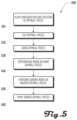
- FIG. 5illustrates a block diagram of method of installing drywall in accordance with one embodiment.
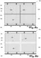
- FIGS. 8 a , 8 b , 9 a , 9 billustrate a series of steps in an example method of installing drywall to generate a wall assembly.
- FIG. 10illustrates an embodiment of a drywalling system sanding a wall assembly in accordance with one embodiment.
- FIG. 12illustrates one embodiment of a painting end effector that includes a spray gun that is coupled onto the robotic arm.
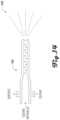
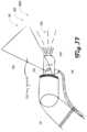
- FIG. 15illustrates an example embodiment of a painting end effector that includes a spray pattern detection mechanism, in which a vision system can be used to monitor the pattern of paint spray coming out of the nozzle to detect clogs, nozzle wear, low pressure, or other problems with the spray gun or related system such as paint lines, paint source, or the like.
- a vision systemcan be used to monitor the pattern of paint spray coming out of the nozzle to detect clogs, nozzle wear, low pressure, or other problems with the spray gun or related system such as paint lines, paint source, or the like.
- FIG. 16illustrates an example embodiment of a painting end effector that comprises a vacuum system that includes a vacuum hood disposed around an end and nozzle of a spray gun to capture overspray.
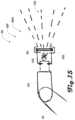
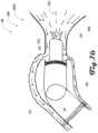
- FIG. 17illustrates an example embodiment of a painting end effector that comprises a spray guard that partially extends about and past the face of the nozzle of the spray gun.
- FIG. 18illustrates an example embodiment of a painting end effector that comprises a first blower and a second blower.
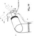
- FIG. 19illustrates an example embodiment of a painting end effector, which comprises a nozzle cassette system where a cassette of nozzles is attached to the end of the spray gun.
- FIG. 20illustrates another example embodiment of a painting end effector that comprises a nozzle rotating system that can be part of a spray gun.
- the following disclosurepertains to an automated drywalling system, which in some embodiments can be used for drywalling, including one or more of planning a configuration and location of drywall pieces on a wall assembly, cutting drywall pieces, hanging drywall pies, performing mud work on hung drywall pieces, performing sanding on mudded drywall pieces and painting sanded drywall pieces.
- the present disclosurepertains to an automatic systems and methods for painting and applying protective coatings onto a substrate.
- the systemcan be used to mix, deliver, apply, and/or dry paint on drywall boards.
- the systemcan used to apply wallpaper on drywall boards.
- the systemcan also be used with any other suitable coatings including varnishes, films, polymer coatings, and the like, which can be applied onto any suitable substrate including drywall, wood, metal, polymers, or the like.
- the systemcan be configured for handling how such a coating is prepared, how it is delivered onto the substrate and how it is set, cured or dried.
- FIGS. 1 and 2examples of an automated drywalling system 100 are illustrated, which includes a base unit 120 , a robotic arm 140 and an end effector 160 .
- the base unit 120comprises a platform 122 and a cart 124 with a lift 126 disposed between the platform 122 and cart 124 .
- the cart 124can be configured to be disposed on the ground and move within an XY plane defined by axes X and Y, and the lift 126 can be configured to raise the platform 122 up and down along axis Z, which is perpendicular to axes X and Y.
- the robotic arm 140can comprise any suitable robotic arm system, which can include pneumatic actuators, electric actuators, and the like.
- the robotic arm 140can have any suitable number of degrees of freedom.
- FIGS. 1 and 2illustrate an example having pneumatic actuator units 146 separated by arm couplers 148 , this example configuration should not be construed to be limiting on the wide variety of robotic arms 140 that are within the scope and spirit of the present disclosure.
- connections between the control system 322 and respective vision systems 324 , 364 ; respective sensors 326 , 346 , 366 ; respective movement systems 328 , 348 , 368 ; and end effector devices 370can comprise any suitable type of connection including wired and/or wireless connections.
- such connectionscan be configured for digital and/or analog communication of information between respective elements.
- the vision systems 324 , 364can comprise one or more suitable vision systems including one or more visible spectrum camera, radar, light detection and ranging (LIDAR) system, sonar, infrared camera, thermal camera, stereo cameras, structured light camera, laser scanners, and the like.
- the vision systems 324 , 364can comprise the same or different elements. Additionally, in some embodiments, one or both of the vision systems 324 , 364 can be absent.
- the robotic arm 140can comprise a vision system.
- the sensors 326 , 346 , 366can comprise any suitable sensors in various embodiments including one or more sensors of humidity, temperature, air flow, laser curtains, proximity sensors, force and torque sensors, pressure sensors, limit switches, rotameter, spring and piston flow meters, ultrasonic flow meters, turbine meters, paddlewheel meters, variable area meters, positive displacement, vortex meters, pitot tube or differential pressure meters, magnetic meters, humidity sensors, conductivity sensors, and depth or thickness sensors.
- the sensors 326 , 346 , 366can comprise the same or different elements. Additionally, in some embodiments, one or more of the sensors 326 , 346 , 366 can be absent.
- the cutting end effector 160 Ccan be coupled at the distal end 144 of the robotic arm 140 and coupled with the power line 436 to power cutting devices 462 of the cutting end effector 160 C.
- the cutting end effector 160 Ccan be controlled by the automated drywalling system 100 to cut drywall or perform other cutting operations.
- the cutting end effector 160 Ccan comprise a cutting vacuum that is coupled to vacuum source 422 via the vacuum line 424 to ingest debris generated by cutting done by the cutting end effector 160 C.
- the hanging end effector 160 Hcan alternatively be coupled at the distal end 144 of the robotic arm 140 and coupled with the power line 436 to power hanging devices 464 of the hanging end effector 160 H.
- the hanging end effector 160 Hcan be controlled by the automated drywalling system 100 to hang drywall, assist with drywall hanging, or the like.
- the painting end effector 160 Pcan alternatively be coupled at the distal end 144 of the robotic arm 140 and coupled with the power line 436 to power a paint sprayer 474 and/or painting devices 476 of the painting end effector 160 P.
- the painting end effector 160 Pcan be controlled by the automated drywalling system 100 to paint drywall or other surfaces. Additionally, the painting end effector 160 P can comprise a painting vacuum 472 that is coupled to vacuum source 422 via the vacuum line 424 to ingest excess paint spray generated by painting done by the painting end effector 160 P.
- the example automated drywalling system 100 of FIG. 4is illustrated having five modular end effectors 160 , other embodiments can include any suitable plurality of modular end effectors 160 , with such end effectors 160 having any suitable configuration, and being for any suitable task or purpose.
- the automated drywalling system 100can comprise a single end effector 160 , which can be permanently or removably coupled to the robotic arm 140 .
- a given end effector 160can be configured to perform a plurality of tasks.
- an end effector 160can be configured for mud work, sanding and painting. Accordingly, the example of FIG. 4 should not be construed to be limiting on the wide variety of other embodiments that are within the scope and spirit of the present disclosure.
- a method 500 of drywallingis illustrated, which can be performed in whole or in part by an automated drywalling system 100 as discussed herein.
- the example method 500 or portions thereofcan be performed automatically by the automated drywalling system 100 with or without user interaction.
- the method 500begins at 510 , where a configuration and location of drywall pieces is planned.
- the automated drywalling system 100can be configured for automated scanning and mapping of a worksite (e.g., framing elements of a house or building) and automated planning of the shapes and sizes of drywall to be disposed at the worksite to generate walls, ceilings, and the like.
- Such scanning and mappingcan include use of vision systems 324 , 364 ( FIG. 3 ) and the like.
- Planning of shapes and sizes of drywallcan be based at least in part on the scanning and mapping and can be performed by a computing device 100 of the automated drywalling system 100 or other suitable device which can be proximate or remote from the automated drywalling system 100 .
- such planningcan be based at least in part on building plans or maps that were not generated by the automated drywalling system 100 .
- the method 500continues to 520 , where drywall pieces are cut.
- Such cuttingcan be based at least in part on the scanning, mapping and planning discussed above. Additionally, such cutting can be performed by the automated drywalling system 100 at a worksite (e.g., via a cutting end effector 160 C) or can be performed by a system remote from the worksite and generated drywall pieces can be delivered to the worksite.
- generated pieces of drywallcan be hung at the worksite, including hanging on studs, beams, posts, wall plates, lintels, joists, and the like, to define walls, ceilings and the like. Screws, nails or other suitable fasteners can be used to hang the drywall pieces.
- the automated drywalling system 100can be configured to hang drywall pieces including positioning the drywall pieces and coupling the drywall pieces in a desired location.
- the automated drywall system 100can be configured to assist a user in hanging drywall, including holding the drywall and/or tools in place while the user fixes the drywall pieces in place.
- a hanging end effector 160 Hcan be used for such drywall hanging.
- mud workcan be performed on the pieces of hung drywall.
- joint compoundknown also as “mud”
- mudcan be applied to seams or joints between adjacent pieces of drywall, over faces of the drywall, and/or can be applied over fasteners such as drywall screws or the like.
- a mudding end effector 160 Mcan be used to perform such mud work.
- sandingcan be performed on the mudded pieces of drywall.
- the joint compoundcan be allowed to dry and can then be sanded by a sanding end effector 160 S of an automated drywall system 100 .
- sandingcan be performed to smooth out joint compound to generate a planar or otherwise consistent profile on the pieces of drywall in preparation for painting.
- the sanded drywall piecescan be painted.
- a painting end effector 160 P of an automated drywalling system 100can be used to paint the drywall pieces.
- the method 500 of FIG. 5relates to hanging and finishing drywall
- other hanging and finishing methodscan similarly be employed by the automated drywalling system 100 , including methods related to hanging particle board, plywood, sheet rock, laminate, tile, wall boards, metal sheeting, lath and the like.
- the methodscan be used with different coatings including plaster, polymer coatings, cement, stucco, organic coatings, and the like. Accordingly, the method 500 of FIG. 5 should not be construed to be limiting.
- automated drywalling system 100can apply a layer or profile of compound that is greater than a thickness that is conventionally manually applied by human workers to allow for a sanding system (e.g., a sanding end effector 160 S) to sand down the compound to a desired plane.
- a sanding systeme.g., a sanding end effector 160 S
- manual joint compound application mudcan be profiled to taper from high points.
- the automated drywalling system 100can apply a thicker layer than normal enabling a sanding system to sand down high points to be level to the adjacent surfaces.
- FIGS. 6 a , 6 b , 6 c , 6 d and 6 eillustrate one example of a mud application profile for a pair of drywall pieces 610 A, 610 B that form a seam 620 , where joint compound 630 is applied over consecutive layers, which can include joint tape 640 , to taper out the high points of joint compound 630 over a wider area. Sanding can then be used to smooth out the final profile.
- the high points of joint compound 630can be caused by various features, including the seam 620 , feature, raised stud, defect, or any combination of these.
- such a mud applicationcan be undesirable for automated application; however, in further embodiments, such a mud application profile can be employed by an automated system such as the automated drywalling system 100 .
- FIGS. 7 a and 7 billustrate an example joint compound application process where the joint compound 630 is applied in a thick layer using a sprayer that generates a mud spray 700 .
- Such an application processcan be performed by the automated drywalling system 100 in various embodiments.
- the thickness of the joint compound 630 being applied to the pieces of drywall 610 A, 610 B defining the seam 620can allow for a sanding system to be used to sand back high points of joint compound 630 to a level surface.
- the high points of joint compound 630can be caused by the seam 620 , feature, raised stud, defect, or any combination of these.
- FIGS. 8 a , 8 b , 9 a and 9 bexamples of a wall assembly 800 including a plurality of drywall pieces 610 A, 610 B, 610 C, 610 D is illustrated.
- the wall assembly 800can comprise a header 810 and footer 820 , with a plurality of studs 830 extending therebetween.
- the drywall pieces 610can be coupled to the studs 830 via a plurality of fasteners 840 (e.g., drywall screws) that extend though the drywall pieces 610 and into the studs 830 .
- the drywall pieces 610can define one or more seams 620 , including in the example of FIG.
- FIG. 10illustrates one example embodiment of the automated drywall system 100 , having a painting end effector 160 P that is configured to generate a paint spray.
- the system 100is shown comprising a robotic arm 140 with a painting end effector 160 with integrated overspray or fume collection 1005 .
- the robotic arm 140 and end effector 160are shown mounted on a mobile base 120 with a vertical lift 126 .
- the base unit 120can carry supporting systems for the automated drywall system 100 as discussed herein.
- the present disclosurepertains to automatic systems and methods for painting and applying protective coatings onto a substrate.
- the system 100can be used to mix, deliver, apply, and/or dry paint on drywall boards 610 .
- the system 100can be used to apply wallpaper on drywall boards.
- the system 100can also be used with any other suitable coatings including varnishes, films, polymer coatings, and the like, which can be applied onto any suitable substrate including drywall, wood, metal, polymers, or the like.
- the system 100can be configured for handling how such a coating is prepared, how it is delivered onto the substrate and how it is set, cured or dried.
- the system 100can include one or more vision systems 324 , 364 and/or sensors 326 , 346 , 366 (e.g., humidity, temperature, air flow sensors, or the like) to establish environmental conditions for a painting.
- the automated drywalling system 100can utilize data from such environmental sensors to determine a desired paint composition, set path parameters such as feed speed, thickness of coating applied, roller pressures, paint sprayer settings, and the like.
- Environmental information in conjunction with paint parameterscan be used to determine or estimate drying times for the paint allowing the system 100 to plan when a next step should begin.
- the system 100can also determine when applied paint has set and dried with one or more of the vision systems 324 , 364 and/or sensors 326 , 346 , 366 .
- the system 100can make such a determination by identifying the moisture content of target surfaces by measuring thermal conductivity of the target surfaces; using a thermal imaging camera or thermometer (contact or non-contact); by detecting differences in colors using a camera, or any combination of these.
- Thermal measurementscan be used to infer the moisture content of applied paint and/or a substrate on which the paint has been applied by comparing the temperature of the paint to the surrounding materials. For example, as water or other solvent evaporates from an applied paint mixture, the temperature of the paint can be lower than that of the surrounding materials.
- Models of a paint drying processcan also be used to estimate the time to dry or cure given a set of starting conditions and information about the environment.
- the vertical lift 126can be used to lift or lower the platform 122 , robotic arm 140 , end effector 160 , positioning stage, gantry or painting tools.
- the lift 126can be instrumented with a position sensor that can be used to capture and control the height of the lift 126 .
- a mapping system or planner system of an automated drywalling system 100can also take as an input a layout of how the drywall boards 610 were hung in the room to locate seams 620 .
- This layoutcan be an input from the automated drywalling system 100 generated at other stages of a drywalling project performed by the automated drywalling system 100 , including drywall planning, drywall cutting, drywall hanging, drywall mudding, drywall sanding, and the like.
- the location of the framing, type of anchors used and layout of the drywall 610can provide information on the planarity, flatness of the wall, and location of high or low points.
- the automated drywalling system 100can include a computational planner (e.g., a program executed by the control system 322 or other suitable device), which can utilize a map uploaded to the system 100 and/or a map created by the mapping system to determine tool paths and/or tool parameters required to achieve a desired paint coating application.
- the plannercan create toolpaths off a global map of the room and then update these paths given updated local measurements once the base unit 120 , robotic arm 140 , and/or end effector 160 are in place.
- the plannercan be informed by data from one or more of the vision systems 324 , 364 and/or sensors 326 , 346 , 366 on the flatness of the wall, user inputs, location of seams 620 as specified by a layout planner or a scan of the room after the substrate was applied, or the like.
- the plannercan produce toolpaths and/or tool parameters, which can enable the system 100 to apply paint, wall paper or other coatings to surfaces.
- the tool parameters and/or tool pathscan also be determined by a desired or defined finish of the coating. For example, areas that are exposed to changing, harsh, or bright lights can receive a higher quality finish with tighter controls on paint thickness, overlaps, textures, wall paper seam location, and the like.
- 2D or 3D maps created by the system 100can be registered to the physical environment utilizing recognizable features such as doors, windows, outlets, corners, or the like.
- the registrationcan also be done using markers, tags, laser outlines, or the like that are placed in the room or worksite.
- a projection or visualization systemcan find such features or markers and can locate the maps created using these.
- the system 100can utilize a user interface to enable a user to help locate the map or projection relative to the environment and resolve any issues or discrepancies.
- the usercan utilize a physical marker to signify key features for the system 100 allowing it to locate the plan relative to the environment.
- the system 100can also use the base unit 120 , robotic arm 140 , and/or end effector 160 to find target features, markers or surfaces and locate them relative to its own base which can be located using one or more vision systems 324 , 364 and/or sensors 326 , 346 , 366 , which in some examples can include laser range finders, computer vision, LIDAR, radar, sonar, stereo vision, odometry, IMUs, or the like.
- vision systems 324 , 364 and/or sensors 326 , 346 , 366which in some examples can include laser range finders, computer vision, LIDAR, radar, sonar, stereo vision, odometry, IMUs, or the like.
- the robotic arm 140can utilize a compliant or force limiting end effector 160 to enable safe contact with the environment allowing the system 100 to accurately locate target surfaces, features or components, accommodate errors in positioning without damaging the substrate or the robotic arm 140 or end effector 160 .
- the system 100can establish a point, line, or plane and therefore locate the virtual plan on the environment. Toolpaths can then be updated from the virtual plane to the physical plane. Refitting of the paths onto the contacted surfaces enables the system 100 to deal with errors and discrepancies between the modeled and physical environment.
- Refitting the tool pathscan allow for correction of errors in positioning of the base unit 120 , robotic arm 140 , and/or end effector 160 .
- the base unit 120 , robotic arm 140 , and/or end effector 160can also utilize one or more vision systems 324 , 364 (e.g., radar, sonar, thermal imaging, or the like) to establish what is behind the substrate, and this information can be used to update a virtual map and ensure that no damage is done to any electrical, plumbing or ventilation.
- vision systems 324 , 364e.g., radar, sonar, thermal imaging, or the like
- the planner of the system 100can output tool poses or tool paths for the base unit 120 , robotic arm 140 , and/or end effector 160 , including joint commands, target poses and end effector positions, or the like.
- the system 100can also output paths for a gantry system or positioning stage which can be used in conjunction with the robotic arm 140 , or without a robot, to move and position coating tools of an end effector 160 .
- the plannercan also output paths for the mobile base 120 to position a gantry, positioning stage, or robotic manipulator 140 , to move a tool to assist the user in the finishing process, or position visualization and/or lighting equipment.
- the mobile base 140 including the vertical lift 126can work in coordination with the user, robotic manipulator 140 , end effector 160 , gantry or a combination of these to execute a painting or coating task.
- the planner systemcan control the different components of the platform such as the base unit 120 , robotic arm 140 , and/or end effector 160 , which can allow for coordinated movements and forces with the target goal of moving the end effector 160 to a desired position under the prescribed forces and moments.
- the position of the mobile base 120can be used as a rough positioning stage, with the vertical lift 126 setting a height of the robotic manipulator 140 which can act as a fine positioning stage.
- FIG. 11illustrates an example embodiment of a wallpaper applicator end effector 160 W, wherein a roll of wallpaper 1110 is mounted within a roll body 1120 of the end effector 1130 and fed through a blade 1130 .
- the wallpaper end effector 160 Wcan be moved over a target surface and the blade 1130 can press down the wallpaper onto the surface.
- adhesivecan be present of the rolled wallpaper 1100 applied to the wall, or the wallpaper 1110 can be without an adhesive and the wallpaper 1110 can be applied over an adhesive that has been applied to the target surface.
- an adhesivecan be applied with an end effector 160 by spraying.
- Some examplescan include a separate end effector 160 having an adhesive spray gun, or an adhesive spray gun can be part of a wallpaper end effector 160 W, that is configured to apply adhesive in front of the wallpaper 1110 onto a surface that the wallpaper 1110 is being applied to and/or by applying the adhesive onto the wallpaper 1110 before the blade 1130 .
- the wallpaper 1110can come pre-impregnated with adhesive in some examples.
- the system 100can utilize various suitable end effectors 160 to automatically dispense and apply wallpaper 1110 on drywall boards 610 or other suitable substrate.
- the wallpaper 1110can be fed off a roll onto a wall after being covered with adhesive.
- the adhesiveis delivered ahead of the wallpaper 1110 through a roller, sprayer, brush, or the like and the wallpaper 1110 is applied onto the surface using a blade, trowel, roller, or the like. Tracking the position of a wallpaper end effector 160 W with one or more of the vision systems 324 , 364 and/or sensors 326 , 346 , 366 can enable the planner system to create an updated map of the room with the location of the wallpaper 1110 and the conditions under which the wallpaper was applied.
- the one or more of the vision systems 324 , 364 and/or sensors 326 , 346 , 366can use tags or markers to track as a user manually applies the wallpaper 1110 on the surfaces and that information can be fed into the planner.
- the base unit 120 , robotic arm 140 , and/or end effector 160can be used to control the orientation of wallpapering tools of the end effector 160 and the force applied on the target surface as the wallpaper 1110 is applied, which can ensure the wallpaper 1110 is applied with the required pressure for adhesion.
- FIG. 12illustrates one embodiment 160 P 2 of a painting end effector 160 P that includes a spray gun 1210 that is coupled onto the robotic arm 140 .
- a trigger 1220can be actuated with an actuator 1230 (e.g., a servo, solenoid, pneumatic cylinder, or the like) which can pull on the trigger 1220 to open the nozzle 1240 to generate a paint spray 1250 .
- an actuator 1230e.g., a servo, solenoid, pneumatic cylinder, or the like
- FIG. 13illustrates another embodiment 160 P 3 of a painting end effector 160 P that includes a spray gun 1210 that is coupled onto the robotic arm 140 .
- An internal trigger(not shown) can be actuated with an actuator (e.g., a servo, solenoid, pneumatic cylinder, or the like) which can open the nozzle 1240 to generate a paint spray 1250 .
- an actuatore.g., a servo, solenoid, pneumatic cylinder, or the like
- paintcan be fed to the spray gun 1240 and nozzle 1240 via a paint tube 428 , which can feed paint (or other suitable coatings in further embodiments) from a paint source 426 disposed at the base unit 120 (See FIG. 4 ).
- a painting end effector 160 Pis used to deliver paint or other suitable coating to a target surface.
- a spray gun 1210can comprise an airless spray system or air assisted spray system.
- a pumpcan be used to move the paint 930 from the paint source 426 to the spray gun 1210 .
- the paint 930can be pumped at high pressures, in some examples, to enable the paint 930 to be sprayed or aerosolized.
- high paint particle speedscan produce a smoother finish, which can be desirable in some examples.
- the pressure, flow rate, piping system resistance and the like,can be tuned or controlled by the automated drywalling system 100 to change the speed and amount of paint 930 being delivered to the spray gun 1210 and ejected from the nozzle 1240 as a spray 1250 .
- the automated drywalling system 100can use any suitable actuator (e.g., a servo, solenoid, air cylinder, linear actuator, or any combination of these) to open and close the nozzle 1240 of the spray gun 1210 .
- a manual spray gun 1210can be instrumented to use an electromechanical system 1230 to pull the trigger 1220 allowing the system 100 to control the timing of the joint compound delivery as well as the opening and closing of the nozzle 1240 .
- an automatic spray gun 1210can also be used and controlled by the system 100 directly.
- the robotic arm 140 and end effector 160 and/or base unit 120can thereby be used to spray paint 930 as a spray 1250 onto surfaces of drywall pieces 610 and/or seams 620 defined by one or more drywall pieces 610 , which can be covered by joint compound 630 and/or joint tape 640 .
- the painting end effector 160 Pcan also be used to apply adhesive onto the surface for wallpaper application.
- the automated drywalling system 100can include a mixer, pump and the like that can deliver mixed paint 930 to the various tools including a spray gun 1210 .
- a mixer, pump and the likecan be part of a paint source 426 disposed at the base unit 120 or disposed external to the system 100 .
- a mixercan utilize sensors to control a mixing ratio of water, slurry, pigments, or dry coating material, and any additives that enhance structure of the coating material, color the coating material, decrease setting or drying time, or the like.
- the mixercan control the mix ratio by measuring the mass, volume, density, or viscosity of the components or the mixture that defines the paint 930 or other coating material.
- the mixing systemcan utilize pre-mixed paint 930 or can add water and/or additives as desired to a mixture.
- the automated drywalling system 100can also tune the profile of a delivered coating of paint 930 (or other suitable coating) to account for overlap of a subsequent stroke of a paint gun 1210 or other painting tool. For example, paint thickness at the edges can be reduced or feathered such that the overlap region achieves the final desired thickness. This approach can also be used to increase overlap error tolerance at transition points between robot workspaces.
- the automated drywalling system 100can utilize the information about the room such as location of windows and lighting fixtures to tune the painting toolpaths to achieve the most consistent finish near these features.
- the automated drywalling system 100can optimize the path to minimize overlaps or breaks in the stroke near the light sources.
- the system 100can also apply the coating in a criss-cross pattern to create a more even thickness or better finish.
- the planner system of the automated drywalling system 100can output paths that guide the tool in this criss-cross pattern.
- the automated drywalling system 100can be instrumented with one or more vision systems 324 , 364 and/or sensors 326 , 346 , 366 to improve operation and ensure quality.
- the automated drywalling system 100can use sensors 326 , 346 , 366 (e.g., force and torque sensors), which can be mounted directly on the base unit 120 , robotic arm 140 , and/or end effector 160 , or the force and torque estimates of robotic joints can be used to apply the required force during rolling or smoothing.
- the sensors 326 , 346 , 366can monitor only force normal to a blade, rollers or the like, or multiple axes can be monitored including torque measurements and six-axis sensing.
- Force sensingcan be used to control the force or pressure applied by the tool of an end effector 160 .
- a minimum force or contact readingcan also be used to ensure contact is made with a target surface before the paint 930 or other coating material is allowed to flow, with target surface contact force below a certain threshold or loss of contact triggering the stop of material flow.
- the automated drywalling system 100can use force information to operate in force control, where the motions and speeds of the system 100 are driven to ensure a given force is applied in the desired directions.
- force sensingcan be used to detect contact with an object, obstacle, or intersecting wall or ceiling.
- the system 100can detect that it has made contact with the adjacent wall or ceiling and alter the toolpath accordingly.
- the measurementscan also be used to detect accidental contact and trigger a safety operation such as stopping the system 100 or retracting away from the contact point.
- the base unit 120 , robotic arm 140 , and/or end effector 160can also use contact or proximity sensors to detect that the end effector 160 is touching a target surface, obstacle, object, or worker, as well as detect the distance to an adjacent surface or contact with that surface.
- the force, contact, displacement, or proximity sensorscan be mounted on outriggers from the end effector to sense obstacles, objects, or adjacent surfaces ahead of the tool.
- any problems, issues, or bugscan be reported in the user interface.
- Lights on the end effector 160 , mobile base 120 and/or robotic arm 140 as well as soundscan also be used to indicate problems such as movement of the end effector 160 , base unit 120 and/or robotic arm 140 ; that work is in progress; that the system 100 is on or off; that the toolpath is running or paused; that the system 100 needs attention or refill of materials; and any other indicators of the system state.
- the user interfacecan also display information on the progress, task and tool parameters, and quality metrics of the task being performed.
- Environmental conditionscan also be displayed and recorded by the interface.
- the system 100can indicate to the user what steps to take to correct or improve conditions including air quality, temperature and humidity.
- FIG. 20illustrates another example embodiment 160 P 10 of a painting end effector 160 P that comprises of a nozzle rotating system 2005 that can be part of a spray gun 1210 .
- the system 100can utilize an actuator assembly 2010 (e.g., a servo or other electromechanical actuator) to rotate (e.g., 180 degrees) a portion 2015 of the nozzle 1210 allowing for paint 930 to go through the nozzle portion 2015 in reverse helping clear out clogs.
- an actuator assembly 2010e.g., a servo or other electromechanical actuator
- the system 100can generate reports and interface with other software platforms including BIM packages. Reports can be created that can be used for inspection and certification. A report can be customized to provide the information required to pass a standard, test, or certification. The reporting system can also provide a live update of the current task progress and live camera feed. This information can be used to help track asset performance and work progression.
- the datacan be reported to a BIM system or other software to facilitate planning of other trades, next steps, or schedule inspections or other tasks.
- the reportscan include full maps of the paint 930 applied and tool and path parameters utilized to complete the task. Further images or video can be recorded to facilitate quality checks or for tracking of issues.
- the system 100can record parameters used to complete the task which can be fed to a machine learning software to enable the system 100 to learn from past work.
- the reportscan also be used to optimize workflow and scheduling.
- the system's optimization functioncan be updated to meet the desired needs including minimizing task time, completion of the task in a part of the worksite to allow other trades to come in, minimizing cost, optimal use of assets and workforce, among others.
- the system's reportscan also include information on environmental conditions and how the process was changed given the conditions.
- the system 100can create a report that shows the process parameters that were used to cover the surface as well as the order of operations.
- the reportcan include BIM, 3D and 2D maps or plans, images, and/or video.
- the maps provided by the system 100can be used to facilitate repairs and maintenance by providing the customer with the location of components behind the wall as well as the location of seams to facilitate the removal of panels or boards.
- the updated room models that reflect the as built conditions and measurementscan be exported for use in sanding the walls or for certification of quality at delivery.
- a complete map of the thickness of the paint 930 applied with or without shrinkingcan be fed into the system 100 or a separate automated sanding system which can plan tool paths and parameters desired to achieve the desired finish by sanding.
- the system 100can work in conjunction with a larger system that plans the full process from mapping a room, to cutting and hanging the drywall to finishing and painting of the surfaces.
- This system 100can be used for coating surfaces with any suitable material, including but not limited to, joint compound 630 , plaster, stucco, cement, paint 930 , polymer coating, lacquers, varnishes, or any combination of these.
- the system 100can apply the coatings on any suitable substrate, including but not limited to, drywall, boards, lath, mesh, or other substrates.
- the system 100can also be used to apply other coverings such as wallpaper, polymer films, or the like.
Landscapes
- Engineering & Computer Science (AREA)
- Architecture (AREA)
- Mechanical Engineering (AREA)
- Civil Engineering (AREA)
- Structural Engineering (AREA)
- Robotics (AREA)
- Physics & Mathematics (AREA)
- Life Sciences & Earth Sciences (AREA)
- Forests & Forestry (AREA)
- Computer Vision & Pattern Recognition (AREA)
- Plasma & Fusion (AREA)
- Acoustics & Sound (AREA)
- Electromagnetism (AREA)
- Manipulator (AREA)
- Spray Control Apparatus (AREA)
- Conveying And Assembling Of Building Elements In Situ (AREA)
Abstract
Description
Claims (20)
Priority Applications (1)
| Application Number | Priority Date | Filing Date | Title |
|---|---|---|---|
| US17/968,372US12345057B2 (en) | 2017-03-31 | 2022-10-18 | Automated drywall painting system and method |
Applications Claiming Priority (3)
| Application Number | Priority Date | Filing Date | Title |
|---|---|---|---|
| US201762480172P | 2017-03-31 | 2017-03-31 | |
| US15/942,087US11499325B2 (en) | 2017-03-31 | 2018-03-30 | Automated drywall painting system and method |
| US17/968,372US12345057B2 (en) | 2017-03-31 | 2022-10-18 | Automated drywall painting system and method |
Related Parent Applications (1)
| Application Number | Title | Priority Date | Filing Date |
|---|---|---|---|
| US15/942,087ContinuationUS11499325B2 (en) | 2017-03-31 | 2018-03-30 | Automated drywall painting system and method |
Publications (2)
| Publication Number | Publication Date |
|---|---|
| US20230043189A1 US20230043189A1 (en) | 2023-02-09 |
| US12345057B2true US12345057B2 (en) | 2025-07-01 |
Family
ID=63672234
Family Applications (12)
| Application Number | Title | Priority Date | Filing Date |
|---|---|---|---|
| US15/942,318Active2038-05-02US10718119B2 (en) | 2017-03-31 | 2018-03-30 | Automated drywall sanding system and method |
| US15/942,158Active2038-04-17US10513856B2 (en) | 2017-03-31 | 2018-03-30 | Automated drywall planning system and method |
| US15/941,974ActiveUS10870996B2 (en) | 2017-03-31 | 2018-03-30 | Automated insulation application system and method |
| US15/942,286ActiveUS10697188B2 (en) | 2017-03-31 | 2018-03-30 | Automated drywalling system and method |
| US15/941,886Active2038-07-14US10822814B2 (en) | 2017-03-31 | 2018-03-30 | Automated drywall mudding system and method |
| US15/942,087ActiveUS11499325B2 (en) | 2017-03-31 | 2018-03-30 | Automated drywall painting system and method |
| US15/942,193ActiveUS10526799B2 (en) | 2017-03-31 | 2018-03-30 | Automated drywall cutting and hanging system and method |
| US16/589,501ActiveUS11525270B2 (en) | 2017-03-31 | 2019-10-01 | Automated drywall planning system and method |
| US16/689,674AbandonedUS20200087930A1 (en) | 2017-03-31 | 2019-11-20 | Automated drywall cutting and hanging system and method |
| US17/968,372Active2038-08-05US12345057B2 (en) | 2017-03-31 | 2022-10-18 | Automated drywall painting system and method |
| US17/981,777Active2038-05-08US12123205B2 (en) | 2017-03-31 | 2022-11-07 | Automated drywall planning system and method |
| US18/918,534PendingUS20250034886A1 (en) | 2017-03-31 | 2024-10-17 | Automated drywall planning system and method |
Family Applications Before (9)
| Application Number | Title | Priority Date | Filing Date |
|---|---|---|---|
| US15/942,318Active2038-05-02US10718119B2 (en) | 2017-03-31 | 2018-03-30 | Automated drywall sanding system and method |
| US15/942,158Active2038-04-17US10513856B2 (en) | 2017-03-31 | 2018-03-30 | Automated drywall planning system and method |
| US15/941,974ActiveUS10870996B2 (en) | 2017-03-31 | 2018-03-30 | Automated insulation application system and method |
| US15/942,286ActiveUS10697188B2 (en) | 2017-03-31 | 2018-03-30 | Automated drywalling system and method |
| US15/941,886Active2038-07-14US10822814B2 (en) | 2017-03-31 | 2018-03-30 | Automated drywall mudding system and method |
| US15/942,087ActiveUS11499325B2 (en) | 2017-03-31 | 2018-03-30 | Automated drywall painting system and method |
| US15/942,193ActiveUS10526799B2 (en) | 2017-03-31 | 2018-03-30 | Automated drywall cutting and hanging system and method |
| US16/589,501ActiveUS11525270B2 (en) | 2017-03-31 | 2019-10-01 | Automated drywall planning system and method |
| US16/689,674AbandonedUS20200087930A1 (en) | 2017-03-31 | 2019-11-20 | Automated drywall cutting and hanging system and method |
Family Applications After (2)
| Application Number | Title | Priority Date | Filing Date |
|---|---|---|---|
| US17/981,777Active2038-05-08US12123205B2 (en) | 2017-03-31 | 2022-11-07 | Automated drywall planning system and method |
| US18/918,534PendingUS20250034886A1 (en) | 2017-03-31 | 2024-10-17 | Automated drywall planning system and method |
Country Status (4)
| Country | Link |
|---|---|
| US (12) | US10718119B2 (en) |
| EP (4) | EP3600790A4 (en) |
| IL (1) | IL269697B (en) |
| WO (7) | WO2018183937A1 (en) |
Families Citing this family (225)
| Publication number | Priority date | Publication date | Assignee | Title |
|---|---|---|---|---|
| DE102016109919A1 (en)* | 2016-05-30 | 2017-11-30 | Carl Zeiss Ag | Device for measuring objects |
| WO2018006181A1 (en)* | 2016-07-08 | 2018-01-11 | Macdonald, Dettwiler And Associates Inc. | System and method for automated artificial vision guided dispensing viscous fluids for caulking and sealing operations |
| ES2899284T3 (en) | 2016-07-15 | 2022-03-10 | Fastbrick Ip Pty Ltd | Vehicle incorporating a brick laying machine |
| CA3026002C (en) | 2016-09-06 | 2021-04-20 | Advanced Intelligent Systems Inc. | Mobile work station for transporting a plurality of articles |
| WO2018051341A1 (en)* | 2016-09-14 | 2018-03-22 | Erez Halahmi | Monitoring system and method for controlling process of surface treatment for construction |
| US10732127B2 (en)* | 2016-10-26 | 2020-08-04 | Pixart Imaging Inc. | Dirtiness level determining system and surface cleaning machine |
| ES3019565T3 (en)* | 2016-12-07 | 2025-05-20 | Sika Tech Ag | System for tiling and method using this system |
| AU2018211005B2 (en) | 2017-01-17 | 2023-11-02 | Graco Minnesota, Inc. | Systems for automated mobile painting of structures |
| CN111246977A (en)* | 2017-03-30 | 2020-06-05 | 软机器人公司 | User-assisted robot control system |
| WO2018183937A1 (en) | 2017-03-31 | 2018-10-04 | Canvas Construction, Inc. | Automated insulation application system and method |
| DE102017209339A1 (en)* | 2017-06-01 | 2018-12-06 | Henkel Ag & Co. Kgaa | Hair treatment device, hair treatment system and method for the cosmetic treatment of hair |
| WO2019014274A1 (en)* | 2017-07-10 | 2019-01-17 | Hypertherm, Inc. | Computer-implemented methods and systems for generating material processing robotic tool paths |
| CN111213098B (en) | 2017-08-17 | 2024-03-15 | 快砖知识产权私人有限公司 | Communication systems for interactive systems |
| IL272882B (en) | 2017-09-25 | 2022-07-01 | Canvas Construction Inc | Automatic system for planning plaster walls and method |
| US10422144B2 (en)* | 2017-10-02 | 2019-09-24 | United States Gypsum Company | Joint tape embedding apparatus, system, and method |
| JP6678155B2 (en)* | 2017-12-05 | 2020-04-08 | 株式会社大気社 | Control method of surface treatment system |
| DE102018200551A1 (en)* | 2018-01-15 | 2019-07-18 | Festool Gmbh | processing device |
| CA3090827C (en) | 2018-02-15 | 2021-01-19 | Advanced Intelligent Systems Inc. | Apparatus for supporting an article during transport |
| US20190262963A1 (en)* | 2018-02-23 | 2019-08-29 | Temple Allen Holdings Llc | Surface treatment apparatus with selective loading |
| US11162241B2 (en)* | 2018-03-27 | 2021-11-02 | Deere & Company | Controlling mobile machines with a robotic attachment |
| CN112041221B (en)* | 2018-04-04 | 2023-03-21 | 圣-戈贝恩普拉科公司 | Automation device for building panels |
| JP2019191117A (en)* | 2018-04-27 | 2019-10-31 | キヤノン株式会社 | Image processing device, image processing method, and program |
| DE102018111838A1 (en)* | 2018-05-16 | 2019-11-21 | Festool Gmbh | Mobile machine tool |
| US11608648B2 (en)* | 2018-05-17 | 2023-03-21 | Level 6 Technologies, Llc | System of drywall finishing in building construction |
| US11407111B2 (en)* | 2018-06-27 | 2022-08-09 | Abb Schweiz Ag | Method and system to generate a 3D model for a robot scene |
| US12214500B2 (en)* | 2018-07-16 | 2025-02-04 | Fastbrick Ip Pty Ltd | Backup tracking for an interaction system |
| CN112689552A (en) | 2018-07-16 | 2021-04-20 | 快砖知识产权私人有限公司 | Active damping system |
| EP3613544A1 (en) | 2018-08-22 | 2020-02-26 | Hilti Aktiengesellschaft | Mobile construction robot |
| US20200061828A1 (en)* | 2018-08-27 | 2020-02-27 | Ascend Robotics LLC | Automated construction robot systems and methods |
| US10745219B2 (en) | 2018-09-28 | 2020-08-18 | Advanced Intelligent Systems Inc. | Manipulator apparatus, methods, and systems with at least one cable |
| US10751888B2 (en) | 2018-10-04 | 2020-08-25 | Advanced Intelligent Systems Inc. | Manipulator apparatus for operating on articles |
| CN109098416A (en)* | 2018-10-15 | 2018-12-28 | 重庆电讯职业学院 | A kind of ceramic tile laying gripper of industrial robot |
| US10645882B1 (en) | 2018-10-29 | 2020-05-12 | Advanced Intelligent Systems Inc. | Method and apparatus for performing pruning operations using an autonomous vehicle |
| US10966374B2 (en) | 2018-10-29 | 2021-04-06 | Advanced Intelligent Systems Inc. | Method and apparatus for performing pruning operations using an autonomous vehicle |
| CN109162431B (en)* | 2018-10-31 | 2021-03-23 | 陕西理工大学 | High-rise wall spraying robot |
| US20200139394A1 (en)* | 2018-11-02 | 2020-05-07 | The Boeing Company | Methods, apparatuses, and systems for smart delivery of coating material |
| TWI681845B (en)* | 2018-11-15 | 2020-01-11 | 財團法人工業技術研究院 | Method and system for controlling polishing and grinding |
| US10676279B1 (en) | 2018-11-20 | 2020-06-09 | Advanced Intelligent Systems Inc. | Systems, methods, and storage units for article transport and storage |
| CN109505398B (en)* | 2018-11-21 | 2020-09-25 | 诸大淼 | Multifunctional paint painting robot device |
| US12296459B2 (en)* | 2018-11-21 | 2025-05-13 | Dusty Robotics, Inc. | Mobile printing robot and related methods |
| US20220009098A1 (en)* | 2018-11-21 | 2022-01-13 | Basf Se | Method and system of manufacturing an insulated member |
| US12397440B1 (en)* | 2018-12-10 | 2025-08-26 | Joseph E. Augenbraun | Robot for performing dextrous tasks and related methods and systems |
| US11407118B1 (en)* | 2018-12-10 | 2022-08-09 | Joseph E Augenbraun | Robot for performing dextrous tasks and related methods and systems |
| EP3898005A1 (en)* | 2018-12-19 | 2021-10-27 | 3M Innovative Properties Company | Automated coating system having smart end-effector tool |
| HUE068878T2 (en)* | 2018-12-23 | 2025-01-28 | Agi Eng Inc | Programmable tank cleaning nozzle |
| KR102008406B1 (en)* | 2019-01-07 | 2019-08-07 | 문윤정 | Finish work method of interior walls of buildings |
| CN109865649A (en)* | 2019-01-18 | 2019-06-11 | 许有坤 | A kind of indoor wall drying unit |
| US11145085B2 (en)* | 2019-01-25 | 2021-10-12 | Social Construct Company | Systems and methods for automating installation of prefabricated parts using projected installation graphics |
| JP7153335B2 (en)* | 2019-01-29 | 2022-10-14 | リバーフィールド株式会社 | Surgery support device |
| CN109702764B (en)* | 2019-01-30 | 2021-11-19 | 西安交通大学 | Multifunctional movable operating robot for polishing and spraying indoor wall |
| US11724404B2 (en) | 2019-02-21 | 2023-08-15 | Canvas Construction, Inc. | Surface finish quality evaluation system and method |
| DE102020001193B4 (en) | 2019-02-27 | 2021-11-18 | Gabriele Kobler | Device for moving, guiding and operating a spray device and method for operating such a device |
| CN110026312A (en)* | 2019-03-01 | 2019-07-19 | 深圳市联天钢结构桥梁工程有限公司 | A kind of steel structure anti-corrosion paint coating equipment |
| CA3133250A1 (en)* | 2019-03-13 | 2020-09-17 | Firestone Building Products Company, Llc | Sealant dispenser and methods of operation |
| EP3938733A4 (en)* | 2019-03-15 | 2023-03-22 | Certainteed Gypsum, Inc. | METHOD OF CHARACTERIZING A SURFACE TEXTURE AND TEXTURE CHARACTERIZATION TOOL |
| CN109914756B (en)* | 2019-03-19 | 2020-10-16 | 珠海心怡科技有限公司 | Indoor wall 3D putty printing and leveling processing method based on indoor construction intelligent robot |
| CN109958265A (en)* | 2019-03-30 | 2019-07-02 | 广东博智林机器人有限公司 | Grabbing device, tiling device, object position determination method and computer storage medium |
| CN109881871A (en)* | 2019-04-03 | 2019-06-14 | 中南大学 | A large automatic plastering machine |
| CN109986574A (en)* | 2019-04-03 | 2019-07-09 | 灵动科技(北京)有限公司 | Autonomous device |
| FI20195384A1 (en)* | 2019-05-09 | 2020-11-10 | Pitomaalaus Oy | Method, construction site robot and computer program product for performing a work procedure |
| CN110107110A (en)* | 2019-05-20 | 2019-08-09 | 河南元邦工程技术有限公司 | A kind of steel clad reinforcement device and application method |
| DE102019003844A1 (en)* | 2019-06-03 | 2020-12-03 | Burkhard Büstgens | Drop-on-demand coating of surfaces |
| EP3747604B1 (en)* | 2019-06-07 | 2022-01-26 | Robert Bosch GmbH | Robot device controller, robot device arrangement and method for controlling a robot device |
| CN110185243B (en)* | 2019-06-11 | 2021-03-02 | 长桥建设集团(深圳)有限公司 | Automatic tracking robot for seam beautifying of floor tiles |
| CN110424683B (en)* | 2019-07-12 | 2024-05-28 | 广东天凛高新科技有限公司 | 3D prints decorative surface layer robot |
| US11953311B2 (en)* | 2019-07-13 | 2024-04-09 | Daniel Dumitru Dorneanu | Smart spray foam depth sensor |
| CN110328690A (en)* | 2019-07-15 | 2019-10-15 | 扬州市神力吊具制造有限公司 | A kind of yaw lifting device |
| CN110409767A (en)* | 2019-07-22 | 2019-11-05 | 安徽京卫宏远科技新材料有限公司 | A kind of exterior coating device and its method for plastering walls of whitewashing a wall |
| CN110424696A (en)* | 2019-07-30 | 2019-11-08 | 广东博智林机器人有限公司 | Milling robot and its control method |
| CN110469087A (en)* | 2019-08-01 | 2019-11-19 | 广州市淞滨工程技术有限公司 | A kind of easy to operate wall surface spraying device for construction |
| CN110528834A (en)* | 2019-08-02 | 2019-12-03 | 合肥融庄电子科技有限公司 | A kind of energy saving and environment friendly intelligent construction painting device |
| CN110552487A (en)* | 2019-08-05 | 2019-12-10 | 徐州市茗尧机械制造有限公司 | Engineering machinery for coloring building wall surface |
| CN110397249B (en)* | 2019-08-09 | 2020-09-25 | 诸暨欧亿自动化设备有限公司 | Integral type wall whitewashes equipment |
| CN110388037A (en)* | 2019-08-19 | 2019-10-29 | 陕西中建建乐智能机器人有限公司 | a painting robot |
| CN110479518B (en)* | 2019-08-22 | 2020-10-23 | 帕格曼科技(太仓)有限公司 | Convenient type flush coater with purification performance |
| CN112096013A (en)* | 2019-09-03 | 2020-12-18 | 绍兴市华获智能装备有限公司 | Efficient building construction wall surface painting device and painting method thereof |
| US11499326B2 (en)* | 2019-09-05 | 2022-11-15 | Hosang Lee | Joint compound application assembly |
| WO2021047753A1 (en) | 2019-09-10 | 2021-03-18 | Abb Schweiz Ag | Methods of determining clogging and clogging characteristics of coating medium apparatus, coating medium apparatus, calibration system and industrial robot |
| CN110694829B (en)* | 2019-09-11 | 2021-01-12 | 北京唯极科技有限公司 | Method for repairing damage of local paint surface on surface of ship |
| CN110694830B (en)* | 2019-09-11 | 2021-01-12 | 北京唯极科技有限公司 | Automatic maintenance device for ship surface |
| US11338576B2 (en) | 2019-09-13 | 2022-05-24 | Dusty Robotics, Inc. | Mobile robot printing with wind protection |
| CN110587609B (en)* | 2019-09-20 | 2022-07-22 | 唐山雄炜机器人有限公司 | Robot rust removal control method and system |
| CN110616879B (en)* | 2019-09-29 | 2020-11-27 | 张书赫 | Wall painting device for indoor decoration and use method thereof |
| CN110841838B (en)* | 2019-10-08 | 2021-07-06 | 深圳市泰达机器人有限公司 | Surface treatment coating industrial robot |
| CN110735516A (en)* | 2019-10-14 | 2020-01-31 | 广东博智林机器人有限公司 | Spraying robot |
| CN110805244B (en)* | 2019-10-16 | 2021-11-12 | 抚州中润新材料科技有限公司 | Wall is with multi-functional coating device that coats based on ratchet joint |
| CN110714597B (en)* | 2019-10-22 | 2021-05-11 | 马衍俊 | Strickling machine |
| WO2021086880A1 (en)* | 2019-11-01 | 2021-05-06 | Basf Se | System and method for applying insulation to a product |
| CN110984538B (en)* | 2019-11-05 | 2021-04-09 | 兰泽(荆门)智能科技有限公司 | Wall tiling machine |
| CN110977620B (en)* | 2019-11-13 | 2021-05-28 | 广东博智林机器人有限公司 | Wall polishing method and polishing robot |
| CN110778073B (en)* | 2019-11-14 | 2021-03-19 | 安徽昌定环境工程有限公司 | A sprinkler device for wall painting |
| CN111021676A (en)* | 2019-11-27 | 2020-04-17 | 安徽省忆德工业刷制造有限公司 | Automatic lifting rolling brush |
| CN111005537B (en)* | 2019-12-06 | 2021-04-09 | 周狄超 | Decoration wall painting tool convenient for paint adhesion and difficult material leakage |
| JP7326139B2 (en)* | 2019-12-09 | 2023-08-15 | 株式会社東芝 | WORK SUPPORT DEVICE, WORK SUPPORT METHOD, PROGRAM, AND WORK SUPPORT SYSTEM |
| JP7309592B2 (en)* | 2019-12-16 | 2023-07-18 | 川崎重工業株式会社 | Robot curved surface scanning control method |
| CN110894752B (en)* | 2019-12-20 | 2024-10-01 | 沈阳航空航天大学 | Installation device for building exterior wall insulation board |
| CN110984524B (en)* | 2019-12-20 | 2021-04-09 | 江西金凯新型墙板科技有限公司 | Light partition plate whitewashes device |
| CN111203773B (en)* | 2020-01-15 | 2021-09-14 | 广东博智林机器人有限公司 | Polishing execution device |
| CN111335584B (en)* | 2020-01-20 | 2021-05-11 | 河南科技学院 | an interior decoration device |
| US11891174B2 (en)* | 2020-02-05 | 2024-02-06 | The Boeing Company | Repair of structures using unmanned aerial vehicles |
| US12194615B1 (en)* | 2020-02-10 | 2025-01-14 | The United States of America as represented by the Secretary of the U.S. Navy | Surface removal system |
| ES1243504Y (en)* | 2020-02-13 | 2020-09-01 | Sosa Gonzalez S L | Autonomous painting robot |
| CN111283884A (en)* | 2020-02-21 | 2020-06-16 | 储小燕 | Method for treating decoration construction wall surface of building outer wall |
| US20210260720A1 (en)* | 2020-02-21 | 2021-08-26 | Wichita State University | Systems and methods for automated sanding |
| MX2022010431A (en)* | 2020-02-25 | 2022-09-07 | 3M Innovative Properties Company | Robotic repair systems and methods. |
| JP2023514449A (en)* | 2020-02-25 | 2023-04-05 | スリーエム イノベイティブ プロパティズ カンパニー | Robot repair system and method |
| CN111255197A (en)* | 2020-03-16 | 2020-06-09 | 梅其珍 | Intelligent machine method and system for outer wall construction |
| CN111270835B (en)* | 2020-03-17 | 2020-12-15 | 山东海汇环保设备有限公司 | Equipment for automatically painting patterns on wall |
| CN111251107B (en)* | 2020-03-18 | 2021-10-22 | 广东博智林机器人有限公司 | Polishing equipment |
| CN111230745B (en)* | 2020-03-19 | 2021-09-10 | 杜旭 | Intelligent building environmental protection wall body equipment |
| CN111350332B (en)* | 2020-03-23 | 2021-07-06 | 常州机电职业技术学院 | A mechanical device for paint spraying |
| WO2021191662A1 (en)* | 2020-03-26 | 2021-09-30 | Tavakolian Amirhossein | Smart robot for preparation and painting buildings walls |
| CN111461980B (en)* | 2020-03-30 | 2023-08-29 | 北京百度网讯科技有限公司 | Performance Estimation Method and Device for Point Cloud Stitching Algorithm |
| CN111421435B (en)* | 2020-04-02 | 2021-01-08 | 泰州学院 | Multi freedom polishing robot |
| US11745356B2 (en)* | 2020-04-07 | 2023-09-05 | Purdue Research Foundation | Autonomous robotic system for placing and fastening paneling material for building construction operations |
| CN111203766B (en)* | 2020-04-20 | 2020-08-14 | 广东博智林机器人有限公司 | Wall surface polishing path planning method, device, equipment and medium |
| CN111576802B (en)* | 2020-04-21 | 2021-09-28 | 赵凌 | Building site is with device of plastering a wall |
| CN111421410B (en)* | 2020-04-27 | 2020-12-11 | 福建永东南建设集团有限公司 | Automatic wall surface polishing equipment |
| NO346361B1 (en)* | 2020-04-29 | 2022-06-27 | Conrobotix As | CONTROL SYSTEM FOR OPERATING WORKING OPERATIONS WITH TOOLS IN A ROBOT ADAPTED FOR TOOL HANDLING |
| CN111530670A (en)* | 2020-04-30 | 2020-08-14 | 重庆见芒信息技术咨询服务有限公司 | Part position error compensation method and system applied to robot spraying field |
| US11590661B2 (en)* | 2020-04-30 | 2023-02-28 | The Boeing Company | Robotic sanding systems and methods |
| CN111809841B (en)* | 2020-06-05 | 2022-01-14 | 河南三林建设集团有限公司 | Cement wall joint cleaning equipment |
| CN111571346A (en)* | 2020-06-15 | 2020-08-25 | 上海雅跃智能科技有限公司 | Multipurpose interior wall processing robot |
| CN111673558A (en)* | 2020-06-16 | 2020-09-18 | 杭州鞍马广告设计制作有限公司马鞍山分公司 | A wall grinding and dust removal device for decoration engineering and its working method |
| CN111622463B (en)* | 2020-06-16 | 2021-07-06 | 杭州鞍马广告设计制作有限公司马鞍山分公司 | A wall glue device for decoration engineering and its working method |
| WO2021257846A1 (en)* | 2020-06-17 | 2021-12-23 | Inovision Software Solutions, Inc. | System and method for defect repair |
| US12303924B2 (en)* | 2020-06-19 | 2025-05-20 | Myro International Pte Ltd. | Robotic assisted wall painting apparatus and method |
| WO2022003122A1 (en)* | 2020-07-02 | 2022-01-06 | Basf Se | Method and system for verifying an application of a foamable material onto a carrier |
| CN111774962A (en)* | 2020-07-06 | 2020-10-16 | 无锡中车时代智能装备有限公司 | Robot polishing control method, industrial personal computer and system for high-speed rail body end wall |
| CA3185104A1 (en)* | 2020-07-09 | 2022-01-13 | Peyman POOSTCHI | System and method for automated production of prefabricated buildings and building components |
| CN111877708B (en)* | 2020-07-15 | 2021-12-21 | 山东圣泽建设有限公司 | Wall cement for building plasters leveling device |
| CN111774966B (en)* | 2020-07-16 | 2022-03-08 | 重庆智能机器人研究院 | Building wall putty operating arm and robot of polishing |
| CN111809837B (en)* | 2020-07-17 | 2021-08-10 | 四川仟坤建设集团有限责任公司 | Spraying and plastering system and method |
| DE102020209308A1 (en)* | 2020-07-23 | 2022-01-27 | Steffen Söll | Method for carrying out a construction process when erecting a structure using at least one construction robot |
| CN111791106B (en)* | 2020-07-24 | 2021-07-30 | 南京溧水高新产业股权投资有限公司 | Wall grinding machine capable of replacing grinding wheel |
| US11820017B1 (en)* | 2020-07-31 | 2023-11-21 | GrayMatter Robotics Inc. | Methods for tracking and replacement of a sanding pad |
| US20250058432A1 (en)* | 2020-07-31 | 2025-02-20 | GrayMatter Robotics Inc. | System for autonomously changing a sanding pad of a sanding head |
| US11938632B2 (en)* | 2020-07-31 | 2024-03-26 | GrayMatter Robotics Inc. | Method for autonomously detecting and repairing defects in a workpiece in surface finishing applications |
| CN111890154B (en)* | 2020-07-31 | 2021-08-31 | 广东博智林机器人有限公司 | Polishing method |
| US11820018B1 (en)* | 2020-07-31 | 2023-11-21 | GrayMatter Robotics Inc. | Method for autonomously scanning, processing, and creating a digital twin of a workpiece |
| CN111877706A (en)* | 2020-08-10 | 2020-11-03 | 武汉合创四联科技发展有限公司 | Wall body spraying equipment for building decoration |
| CN111815078B (en)* | 2020-09-02 | 2020-12-08 | 广东博智林机器人有限公司 | Abutted seam polishing path generation method and device, robot and storage medium |
| CN112031368B (en)* | 2020-09-06 | 2021-10-29 | 重庆万重山智能科技有限公司 | Rack module and intelligent tiling robot thereof |
| CN112031364B (en)* | 2020-09-06 | 2021-10-29 | 重庆万重山智能科技有限公司 | Scrape thick liquid module and intelligent tiling robot thereof |
| CN112144830A (en)* | 2020-09-07 | 2020-12-29 | 山东华宇工学院 | Full-automatic wall painting robot |
| CN112031348A (en)* | 2020-09-15 | 2020-12-04 | 浙江铠甲建筑科技有限公司 | Be used for building wall high efficiency to whitewash device |
| EP3974935A1 (en)* | 2020-09-24 | 2022-03-30 | Sandvik Mining and Construction Oy | Underground vehicle monitoring system |
| CN112177283A (en)* | 2020-09-27 | 2021-01-05 | 孙继娟 | Wall surface painting device and method for building engineering construction |
| CN112139891A (en)* | 2020-09-28 | 2020-12-29 | 靳红艳 | A equipment of polishing of facade outside building for construction |
| JP7574031B2 (en)* | 2020-09-30 | 2024-10-28 | 大和ハウス工業株式会社 | Spraying equipment |
| CN112177284A (en)* | 2020-10-09 | 2021-01-05 | 中山市道格装饰设计工程有限公司 | A wall painting machine |
| CN112317167B (en)* | 2020-10-20 | 2023-06-13 | 淮厦集团有限公司 | Spraying equipment for building construction |
| CN112252676A (en)* | 2020-10-23 | 2021-01-22 | 湖南欧龙艺墅建筑材料有限公司 | Real mineral varnish injection apparatus |
| CN112257788B (en)* | 2020-10-23 | 2023-08-04 | 广东博智林机器人有限公司 | Method and device for determining joint operation point |
| CN112502398A (en)* | 2020-10-30 | 2021-03-16 | 温州博旺联科建筑工程有限公司 | Intelligent robot for spraying outer wall of building low-rise building |
| CN112371378B (en)* | 2020-11-06 | 2021-10-22 | 浙江海洋大学 | An industrial paint spraying equipment for marine ships |
| EP4244573A4 (en)* | 2020-11-10 | 2024-07-31 | Abb Schweiz Ag | ROBOTIC REPAIR PROCESS |
| CN112160560B (en)* | 2020-11-16 | 2021-04-27 | 深圳中大建筑装饰有限公司 | Even roll-coating formula painting device of wall for fitment |
| CN112523473B (en)* | 2020-11-24 | 2021-11-05 | 山东科技大学 | Automatic multifunctional wall whitewashing machine and application |
| CN114575562B (en)* | 2020-12-02 | 2023-02-03 | 广东博智林机器人有限公司 | Paving robot, paving system with paving robot and paving method |
| US20220178525A1 (en)* | 2020-12-05 | 2022-06-09 | James Scott Korman | Method for minimizing and eliminating sheetrock sanding using an illuminating device |
| CN112619968A (en)* | 2020-12-07 | 2021-04-09 | 太仓市多多过滤材料有限公司 | PE microporous plate surface treatment equipment and working method thereof |
| CN112627555B (en)* | 2020-12-08 | 2022-05-20 | 深圳市海诚建筑工程有限公司 | Wall body equipment of caulking for construction |
| CN112609928B (en)* | 2020-12-14 | 2022-04-29 | 深圳市成豪建设集团有限公司 | Method for manufacturing heat-insulating layer of interior decoration engineering |
| CN112663907B (en)* | 2020-12-15 | 2022-12-16 | 广东满大装饰工程有限公司 | Glue spreading device for construction decoration engineering construction |
| JP7173117B2 (en)* | 2020-12-17 | 2022-11-16 | 株式会社安川電機 | Coating system, control device, control method, and program |
| FR3117910B1 (en)* | 2020-12-18 | 2023-04-07 | Exel Ind | Electrostatic powder coating robot, system and method |
| CN112681688A (en)* | 2020-12-21 | 2021-04-20 | 斑马找房(武汉)信息科技有限公司 | Vertical automatic wall tile sticking device for building construction and operation method thereof |
| CN112695982B (en)* | 2020-12-22 | 2022-08-26 | 重庆永联达涂装工程股份有限公司 | Intelligent building brushing equipment |
| CN112681682A (en)* | 2020-12-25 | 2021-04-20 | 曹雨 | Exterior wall painting device for building construction |
| US20220221845A1 (en)* | 2021-01-08 | 2022-07-14 | B/E Aerospace, Inc. | System and method for augmented reality (ar) assisted manufacture of composite structures and bonded assemblies |
| US20240082863A1 (en)* | 2021-01-19 | 2024-03-14 | Arizona Board Of Regents On Behalf Of The University Of Arizona | Robotically applied 3d-sprayable exterior insulation and finish systems (eifs) for building envelope retrofits |
| CN112922280A (en)* | 2021-01-27 | 2021-06-08 | 镇江优智浩搏智能科技有限公司 | Suspension type movable wall painting robot |
| CN113027159B (en)* | 2021-02-26 | 2022-12-09 | 盐城工业职业技术学院 | An automatic cleaning and cleaning device for stains in interior design |
| CN112809773B (en)* | 2021-03-04 | 2022-05-31 | 浙江利越市政园林有限公司 | Hanging clamping type cutting device |
| CN113001294A (en)* | 2021-03-06 | 2021-06-22 | 河南工业职业技术学院 | Architectural decoration engineering wall processingequipment |
| CN113027086A (en)* | 2021-03-12 | 2021-06-25 | 邹鸿 | Wall surface spraying device for building decoration and method thereof |
| GB2605372B (en)* | 2021-03-29 | 2024-09-04 | Q Bot Ltd | An apparatus for working a wet coating on a surface and a method of the same |
| KR20240005871A (en)* | 2021-05-11 | 2024-01-12 | 쓰리엠 이노베이티브 프로퍼티즈 컴파니 | Wiping process in robotic paint repair |
| CN113232004B (en)* | 2021-05-24 | 2022-06-17 | 洛阳理工学院 | A kind of automatic beautiful seam robot and beautiful seam construction method |
| CN113293969A (en)* | 2021-05-31 | 2021-08-24 | 束韬 | Wall plastering equipment for realizing uniform painting of paint by utilizing sliding friction force |
| CN113318878A (en)* | 2021-06-25 | 2021-08-31 | 中国铁建大桥工程局集团有限公司 | Multifunctional four-wheel trolley operation platform for wet joint post-cast strip |
| JP7122451B1 (en)* | 2021-07-08 | 2022-08-19 | アーベーベー・シュバイツ・アーゲー | Coating determination device for coating head and coating system |
| NL2028919B1 (en)* | 2021-08-04 | 2023-02-17 | S Nooijens Beheer B V | Monitoring system for monitoring the insulation of buildings. |
| CN113409394A (en)* | 2021-08-17 | 2021-09-17 | 成都信息工程大学 | Intelligent forking method and system |
| JP7666223B2 (en)* | 2021-08-18 | 2025-04-22 | 新東工業株式会社 | Automatic coating device and automatic coating method |
| CN113815512A (en)* | 2021-08-31 | 2021-12-21 | 江苏澳联科技开发有限公司 | Paint spraying and polishing lifting type engineering truck with auxiliary recovery function |
| CN113663835B (en)* | 2021-09-14 | 2022-04-22 | 兴三星云科技有限公司 | Spraying equipment for door and window machining and forming |
| CN113882628A (en)* | 2021-09-23 | 2022-01-04 | 东台昊之峰建设工程有限公司 | Automatic mortar spraying machine |
| CN113863627B (en)* | 2021-10-12 | 2023-05-16 | 上海建工四建集团有限公司 | Device and method for installing glass plate of high-altitude inclined-plane curtain wall |
| CN114165026A (en)* | 2021-11-03 | 2022-03-11 | 江苏润居建设科技发展有限公司 | Fitment is with whitewashing mechanism |
| CN113996458A (en)* | 2021-11-08 | 2022-02-01 | 陈保庆 | Coating spraying device for building decoration engineering |
| TWI795065B (en)* | 2021-11-10 | 2023-03-01 | 逢甲大學 | Masonry automation system and operation method thereof |
| US20250001609A1 (en)* | 2021-11-16 | 2025-01-02 | 3M Innovative Properties Company | Robotic application of tapes |
| CN114082576B (en)* | 2021-11-23 | 2023-07-18 | 中化学建设投资集团安徽工程有限公司 | Intelligent paint spraying equipment for building |
| WO2023114791A1 (en)* | 2021-12-13 | 2023-06-22 | DECOi Inc. | Sub-dermal jointing for composite panelized building system and method |
| US20230202048A1 (en)* | 2021-12-23 | 2023-06-29 | BotBuilt, Inc. | Systems and methods for a stud plate connector end effector |
| DE102022100401A1 (en) | 2022-01-10 | 2023-07-13 | Dürr Systems Ag | Application system and associated monitoring procedure |
| CN115302376B (en)* | 2022-01-28 | 2023-05-23 | 郑州铁路职业技术学院 | Intelligent polishing and cleaning manipulator for subway rail |
| US12383110B2 (en)* | 2022-02-02 | 2025-08-12 | Bissell Inc. | Displaying a dynamically changing wet clean path of an autonomous floor cleaner |
| DE202022100848U1 (en)* | 2022-02-15 | 2023-06-19 | Robosurf Italia S.R.L. | Robot for simple surface processing, especially wall and ceiling processing |
| JP2023129112A (en) | 2022-03-04 | 2023-09-14 | 新東工業株式会社 | Robot and control method of the same |
| US20230277706A1 (en)* | 2022-03-07 | 2023-09-07 | The Boeing Company | Decontamination of a surface of a material |
| CN114809536B (en)* | 2022-04-11 | 2024-01-26 | 广东博智林机器人有限公司 | Coating robot |
| US20230372968A1 (en)* | 2022-04-20 | 2023-11-23 | FOREMAN TECHNOLOGIES INC., dba PAINTJET | System for autonomously applying paint to a target surface |
| US12257590B2 (en) | 2022-04-20 | 2025-03-25 | Foreman Technologies Inc. | System for detecting thickness of a coating autonomously applied to a structure |
| US11975453B2 (en)* | 2022-05-27 | 2024-05-07 | GrayMatter Robotics Inc. | Method for selective, autonomous processing of regions of a workpiece via three-dimensional sanding |
| WO2023235769A1 (en) | 2022-05-31 | 2023-12-07 | Canvas Construction, Inc. | Robotic material application and/or removal for components |
| CN114950886A (en)* | 2022-06-06 | 2022-08-30 | 东莞理工学院 | A positioning system based on machine vision |
| TWI833261B (en)* | 2022-06-24 | 2024-02-21 | 寶成工業股份有限公司 | Automatic mold spraying system |
| WO2024010871A2 (en)* | 2022-07-06 | 2024-01-11 | Augenbraun Joseph E | Robot for performing dextrous tasks and related methods and systems |
| US12311549B2 (en) | 2022-07-14 | 2025-05-27 | Promise Robotics Inc. | Methods, systems and devices for automated assembly of building structures |
| WO2024092259A1 (en)* | 2022-10-28 | 2024-05-02 | BotBuilt, Inc. | Systems and methods for stud plate connector movement |
| CN115992581B (en)* | 2022-12-14 | 2023-09-01 | 广东建石科技有限公司 | Tile laying method of tile laying robot |
| US12383920B2 (en)* | 2023-02-15 | 2025-08-12 | Nathan John Tobkin | Remote spray foam method |
| US12304055B2 (en) | 2023-02-15 | 2025-05-20 | Nathan John Tobkin | Remote spray foam system for polyurethane insulation foam |
| FR3151799A1 (en)* | 2023-08-03 | 2025-02-07 | Sncf Reseau | System for projecting a product onto a catenary support. |
| US20250058842A1 (en)* | 2023-08-18 | 2025-02-20 | Ghost Robotics Corporation | System and method for a legged robot limb controller for position tracking with base wrench limiting |
| US12420427B1 (en)* | 2023-10-04 | 2025-09-23 | Swimc Llc | Robotic systems and methods for objectively evaluating coating compositions and applicators |
| US20250196365A1 (en)* | 2023-12-14 | 2025-06-19 | Cherkam Ltd. | Control of a spray painting robot with a painting trajectory optimized for energy consumption and process time |
| WO2025199405A1 (en)* | 2024-03-22 | 2025-09-25 | Canvas Construction, Inc. | Targeted removal of material in construction and manufacturing |
| CN118223659B (en)* | 2024-04-08 | 2025-05-02 | 嘉兴市燚龙建材有限公司 | Mounting machine for energy-saving glass for kitchen |
| CN118322218B (en)* | 2024-06-13 | 2024-09-13 | 苏州镒升机器人科技有限公司 | Robot arm control system and method based on force sense and touch feedback |
| CN118963218B (en)* | 2024-08-14 | 2025-01-28 | 荣成市和兴船业有限公司 | A method and system for automatic control of shearing of ship steel plates |
| US12379713B1 (en)* | 2025-01-13 | 2025-08-05 | Applied Robotics, Inc. | Construction workstation with rotatable platform |
Citations (91)
| Publication number | Priority date | Publication date | Assignee | Title |
|---|---|---|---|---|
| SU160667A1 (en) | ||||
| US2088542A (en) | 1933-10-06 | 1937-07-27 | Stokes Machine Co | Automatic coating machine |
| US2514748A (en) | 1946-02-05 | 1950-07-11 | Stefano Albert Di | Waste spray collector |
| US3116882A (en) | 1962-01-25 | 1964-01-07 | Gray Company Inc | Turret-nozzle for paint spray guns |
| US4392336A (en) | 1981-03-13 | 1983-07-12 | Ganssle Jack L | Drywall construction and article of manufacture therefor |
| GB2171222A (en) | 1985-02-16 | 1986-08-20 | Shimizu Construction Co Ltd | Robot spraying system |
| US4941182A (en) | 1987-07-29 | 1990-07-10 | Phoenix Software Development Co. | Vision system and method for automated painting equipment |
| JPH03100265A (en) | 1989-09-13 | 1991-04-25 | Tokyu Constr Co Ltd | Automatic fastening device for board |
| JPH04169659A (en) | 1990-11-01 | 1992-06-17 | Nippon Benchiyaa Kogyo Kk | Ceiling construction robot and ceiling construction method |
| JPH04258468A (en) | 1991-02-13 | 1992-09-14 | Nichias Corp | Robot type spraying apparatus |
| US5175018A (en) | 1989-03-29 | 1992-12-29 | Robotic Vision Systems, Inc. | Automated masking device for robotic painting/coating |
| US5279700A (en) | 1990-05-07 | 1994-01-18 | Drywall Technologies, Inc. | Automated wallboard taping apparatus and process therefor |
| JPH06269709A (en) | 1993-03-18 | 1994-09-27 | Koa:Kk | Moving work floor device for splashproof coating and coating method using the same |
| JPH0766585A (en) | 1993-08-31 | 1995-03-10 | Ohbayashi Corp | Execution method of electromagnetic shield room and its structure |
| US5429682A (en)* | 1993-08-19 | 1995-07-04 | Advanced Robotics Technologies | Automated three-dimensional precision coatings application apparatus |
| JP2645312B2 (en) | 1987-12-09 | 1997-08-25 | 清水建設株式会社 | Method and apparatus for spraying cycloids using twin guns |
| US5670202A (en) | 1994-07-01 | 1997-09-23 | Fanuc Robotics North America, Inc. | Method and system for spraying material in a spray pattern having a variable form and collecting excess material |
| RU2100686C1 (en) | 1992-07-10 | 1997-12-27 | ЦРЦ-Эванс Рихабилитейшн Системс, Инк. | Device for working pipe lines |
| JPH10180178A (en) | 1996-12-27 | 1998-07-07 | Sekisui Chem Co Ltd | Coating method of external wall material for corner |
| US5979520A (en) | 1995-11-03 | 1999-11-09 | Babcock-Bsh Gmbh | Device for smoothing panels or battens |
| US5987591A (en) | 1995-12-27 | 1999-11-16 | Fanuc Limited | Multiple-sensor robot system for obtaining two-dimensional image and three-dimensional position information |
| US6112490A (en) | 1997-03-06 | 2000-09-05 | Meyer; Donald L. | Spray insulation shield apparatus and application method |
| US6149506A (en) | 1998-10-07 | 2000-11-21 | Keltech Engineering | Lapping apparatus and method for high speed lapping with a rotatable abrasive platen |
| US6712238B1 (en) | 2002-10-08 | 2004-03-30 | Spraytex, Inc. | Drywall taping and texture system using bladder pump with pneumatic flip/flop logic remote control |
| US20040159724A1 (en) | 2003-02-04 | 2004-08-19 | Van Der Steur Gunnar | Powder paint spray coating apparatus having selectable, modular spray applicators |
| US20050064804A1 (en) | 2003-09-23 | 2005-03-24 | The Boeing Company | Surface preparation device and method |
| CN1611331A (en) | 2003-10-29 | 2005-05-04 | 中国科学院自动化研究所 | Movable manipulator system |
| US20050120840A1 (en) | 1999-10-13 | 2005-06-09 | Koskovich Jerome E. | Automated board processing apparatus |
| US20060108450A1 (en) | 2003-02-06 | 2006-05-25 | Akzo Nobel Coating International B.V. | Spray gun and process for application of actinic radiation-curable coating |
| US20070000947A1 (en) | 2005-07-01 | 2007-01-04 | Lewis Russell H | Apparatus and methods for dispensing fluidic or viscous materials |
| CN2883554Y (en) | 2005-12-16 | 2007-03-28 | 李勇 | Wall polisher |
| US20070107632A1 (en) | 2005-10-28 | 2007-05-17 | Ball Richard L | Pigmented wall and ceiling spackle |
| US20070151201A1 (en) | 2005-12-21 | 2007-07-05 | Fellinger Thomas J | Sprayed insulation application system having variably locatable components |
| WO2007141320A1 (en) | 2006-06-07 | 2007-12-13 | Bouygues Construction | Device for treating a surface |
| DE102006056179A1 (en) | 2006-11-27 | 2008-06-05 | Bernd Luckas | Grinding head for use in industrial robot, in grinding system, comprises grinding unit for processing surface of workpiece, where connection device is provided for connecting grinding unit to holder |
| US20080168741A1 (en) | 2007-01-11 | 2008-07-17 | The Mattamy Corporation | Wall fabrication system and method |
| US7551058B1 (en) | 2003-12-10 | 2009-06-23 | Advanced Design Consulting Usa, Inc. | Sensor for monitoring environmental parameters in concrete |
| KR20090085809A (en) | 2008-02-05 | 2009-08-10 | 한국건설기술연구원 | Spraying Automation System and Method |
| US20090199690A1 (en) | 2008-02-11 | 2009-08-13 | Yi Sun | Method of controlling a robot for small shape generation |
| US20100010660A1 (en) | 2005-04-11 | 2010-01-14 | The Boeing Company | Method of manufacturing a product using scan targets |
| US20100098871A1 (en) | 2008-10-22 | 2010-04-22 | Honda Motor Co., Ltd. | Spray coating system and method |
| JP2010203055A (en) | 2009-02-27 | 2010-09-16 | Meijo Univ | Substrate sensor, substrate detection mechanism, and robot for interior finish work |
| US20100307279A1 (en) | 2009-06-08 | 2010-12-09 | Re2, Inc. | Robust Manual Connector for Robotic Arm End Effector |
| US20110011222A1 (en) | 2009-07-20 | 2011-01-20 | Garrie Brian Bales | Mobile CNC cutting machine |
| US20110211938A1 (en) | 2008-08-29 | 2011-09-01 | Abb Research Ltd. | Compliant End Of Arm Tooling For A Robot |
| ITMO20100102A1 (en) | 2010-04-06 | 2011-10-07 | A & E Yacht Services S R L | EQUIPMENT FOR THE APPLICATION OF STUCCO, PAINT OR SIMILAR ON A SURFACE TO WORK, PARTICULARLY OF THE TYPE OF HULL OF NAVAL BOATS |
| US20110253291A1 (en)* | 2010-04-20 | 2011-10-20 | Level 7, Llc | Drywall finishing method |
| CN202023345U (en) | 2010-08-11 | 2011-11-02 | 裴新平 | Full-automatic wall sanding machine |
| KR101131918B1 (en) | 2011-11-07 | 2012-04-03 | 동일산건(주) | Method for constructing flame retardancy coating material |
| US20120219699A1 (en) | 2010-09-22 | 2012-08-30 | Hexagon Technology Center Gmbh | Graphical application system |
| US20120316930A1 (en) | 2011-06-10 | 2012-12-13 | William Clemenson | Integrated system and methods for tracking and reporting construction, completion, and inspection status |
| JP5107123B2 (en) | 2008-04-09 | 2012-12-26 | 住友林業株式会社 | Wall surface part removing device, wall surface part removing program, recording medium and precut device |
| WO2013000524A1 (en) | 2011-06-30 | 2013-01-03 | Sata Gmbh & Co. Kg | Easy-to-clean spray gun, attachments for the same, and mounting and demounting methods |
| US20130042480A1 (en) | 2010-05-10 | 2013-02-21 | Autoprod Oy | Method and Apparatus for Manufacturing a Wooden Construction Made of Rod-Like Members |
| US20130167471A1 (en) | 2012-01-03 | 2013-07-04 | Douglas A. Denaro | Adjustable lift table |
| US20130239498A1 (en) | 2010-06-11 | 2013-09-19 | Douglas Charles Owens and Alistair William Capamagian as Co-Trustees for the Nereides Trust | Building system |
| US20130260016A1 (en) | 2012-04-02 | 2013-10-03 | The Boeing Company | Sealant Analysis System |
| US20140022281A1 (en) | 2012-07-18 | 2014-01-23 | The Boeing Company | Projecting airplane location specific maintenance history using optical reference points |
| US20140336818A1 (en) | 2013-05-10 | 2014-11-13 | Cnh Industrial America Llc | Control architecture for multi-robot system |
| US20150112482A1 (en) | 2013-10-17 | 2015-04-23 | Kabushiki Kaisha Yaskawa Denki | Teaching system and teaching method |
| US20150147460A1 (en) | 2012-05-21 | 2015-05-28 | Cmo Di Sodini Dino & C. S.N.C. | Method and apparatus for painting objects |
| US20150336267A1 (en) | 2014-05-21 | 2015-11-26 | Fanuc America Corporation | Learning path control |
| US20150350618A1 (en) | 2012-12-28 | 2015-12-03 | Metaio Gmbh | Method of and system for projecting digital information on a real object in a real environment |
| US20150375390A1 (en) | 2014-03-06 | 2015-12-31 | Encore Automation | Robotic system for applying surface finishes to large objects |
| US9243412B1 (en) | 2013-01-10 | 2016-01-26 | Eric S. Gallette | Apparatus for unrolling rolls of insulation in vertical strips from the top down |
| US20160052012A1 (en) | 2012-10-26 | 2016-02-25 | Fraunhofer-Gesellschaft zur Förderung der angewandten Forschung e.V. | Combination nozzle and device for applying a viscous material to a component edge |
| US20160121486A1 (en)* | 2013-05-23 | 2016-05-05 | Q-Bot Limited | Method of Covering a Surface of a Building and Robot Therefor |
| US20160207220A1 (en) | 2013-09-04 | 2016-07-21 | Eth Singapore Sec Ltd | Method of fabricating a 3-dimensional structure, mesh formwork element for fabricating a 3-dimensional structure, and method of fabricating the same |
| US9427874B1 (en) | 2014-08-25 | 2016-08-30 | Google Inc. | Methods and systems for providing landmarks to facilitate robot localization and visual odometry |
| CN105971253A (en) | 2016-05-22 | 2016-09-28 | 安庆海纳信息技术有限公司 | Self-stabilization lifting type building wall whitewashing robot |
| US20160313294A1 (en) | 2015-04-24 | 2016-10-27 | Ppg Industries Ohio, Inc. | Integrated and intelligent paint management |
| CN106088544A (en) | 2016-06-08 | 2016-11-09 | 以恒激光科技(北京)有限公司 | Building wall auto spray painting machine people |
| US9518870B2 (en) | 2007-06-19 | 2016-12-13 | Verifi Llc | Wireless temperature sensor for concrete delivery vehicle |
| WO2016200439A1 (en) | 2015-06-09 | 2016-12-15 | Integrated Construction Enterprises, Inc. | Construction board installation robot |
| US20170052507A1 (en) | 2015-08-21 | 2017-02-23 | Adam Gabriel Poulos | Portable Holographic User Interface for an Interactive 3D Environment |
| JP2017109294A (en) | 2015-12-18 | 2017-06-22 | 清水建設株式会社 | Robot for construction work |
| US9702830B1 (en) | 2016-01-22 | 2017-07-11 | International Business Machines Corporation | Pavement marking determination |
| WO2017187105A1 (en) | 2016-04-29 | 2017-11-02 | Antoine Rennuit | Automaton for treating a surface |
| US9849594B2 (en) | 2012-03-29 | 2017-12-26 | Kuka Systems Gmbh | Parting device and parting method |
| US20180009000A1 (en) | 2016-07-08 | 2018-01-11 | Macdonald, Dettwiler And Associates Inc. | System and Method for Automated Artificial Vision Guided Dispensing Viscous Fluids for Caulking and Sealing Operations |
| US20180021799A1 (en) | 2016-07-22 | 2018-01-25 | Integrated Construction Enterprises, Inc. | Paint overspray removal shroud |
| US20180223546A1 (en) | 2015-07-31 | 2018-08-09 | Maria Elisabeth Holzweber | Method and device for applying an insulation to buildings |
| US20180281012A1 (en) | 2017-03-31 | 2018-10-04 | Canvas Construction, Inc. | Automated drywall painting system and method |
| WO2018226533A1 (en) | 2017-06-05 | 2018-12-13 | Integrated Construction Enterprises, Inc. | Autonomous painting systems and related methods |
| RU2686421C1 (en) | 2018-04-25 | 2019-04-25 | Федеральное государственное бюджетное учреждение "Всероссийский ордена "Знак Почета" НИИ противопожарной обороны Министерства Российской Федерации по делам гражданской обороны, чрезвычайным ситуациям и ликвидации последствий стихийных бедствий" (ФГБУ ВНИИПО МЧС России) | Method for local protection of an object from fire and device for implementation of method, method for creation of fast-setting barrier with fast-setting foam and mobile robot for creation of fireproof barrier from fast-setting foam |
| US20190255551A1 (en) | 2018-02-22 | 2019-08-22 | Hope Robotics Llc | Autonomous mobile coating applicator |
| JP2019167678A (en) | 2018-03-22 | 2019-10-03 | 戸田建設株式会社 | Tunnel spray control method |
| US20200061866A1 (en) | 2016-09-14 | 2020-02-27 | Armatron Systems, LLC | Method of Reinforced Cementitious Construction By High Speed Extrusion Printing and Apparatus for Using Same |
| JP6713762B2 (en) | 2015-12-18 | 2020-06-24 | 清水建設株式会社 | Construction work robot and method for controlling construction work robot |
| US11059065B2 (en) | 2014-10-22 | 2021-07-13 | Q-Bot Limited | Robotic device |
| US11230008B2 (en) | 2016-09-09 | 2022-01-25 | Dürr Systems Ag | Optimisation method for a coating robot and corresponding coating system |
Family Cites Families (4)
| Publication number | Priority date | Publication date | Assignee | Title |
|---|---|---|---|---|
| JPS5323219Y2 (en) | 1974-07-05 | 1978-06-16 | ||
| SU1789711A1 (en) | 1990-06-05 | 1993-01-23 | Inst Geotekhnicheskoi Mekhanik | Device for performance of concrete spraying |
| JP5981143B2 (en)* | 2009-02-03 | 2016-08-31 | ファナック アメリカ コーポレイション | Robot tool control method |
| JP7215056B2 (en) | 2018-10-04 | 2023-01-31 | 株式会社大林組 | Construction work device and construction work method |
- 2018
- 2018-03-30WOPCT/US2018/025536patent/WO2018183937A1/ennot_activeCeased
- 2018-03-30WOPCT/US2018/025556patent/WO2018183953A1/ennot_activeCeased
- 2018-03-30EPEP18777789.1Apatent/EP3600790A4/enactivePending
- 2018-03-30EPEP18778085.3Apatent/EP3600791A4/enactivePending
- 2018-03-30WOPCT/US2018/025485patent/WO2018183904A1/ennot_activeCeased
- 2018-03-30WOPCT/US2018/025529patent/WO2018183935A1/ennot_activeCeased
- 2018-03-30USUS15/942,318patent/US10718119B2/enactiveActive
- 2018-03-30EPEP18774804.1Apatent/EP3600788A4/enactivePending
- 2018-03-30USUS15/942,158patent/US10513856B2/enactiveActive
- 2018-03-30USUS15/941,974patent/US10870996B2/enactiveActive
- 2018-03-30EPEP18776196.0Apatent/EP3600789B1/enactiveActive
- 2018-03-30ILIL269697Apatent/IL269697B/enunknown
- 2018-03-30USUS15/942,286patent/US10697188B2/enactiveActive
- 2018-03-30WOPCT/US2018/025553patent/WO2018183951A1/ennot_activeCeased
- 2018-03-30USUS15/941,886patent/US10822814B2/enactiveActive
- 2018-03-30USUS15/942,087patent/US11499325B2/enactiveActive
- 2018-03-30WOPCT/US2018/025566patent/WO2018183959A1/ennot_activeCeased
- 2018-03-30WOPCT/US2018/025570patent/WO2018183961A1/ennot_activeCeased
- 2018-03-30USUS15/942,193patent/US10526799B2/enactiveActive
- 2019
- 2019-10-01USUS16/589,501patent/US11525270B2/enactiveActive
- 2019-11-20USUS16/689,674patent/US20200087930A1/ennot_activeAbandoned
- 2022
- 2022-10-18USUS17/968,372patent/US12345057B2/enactiveActive
- 2022-11-07USUS17/981,777patent/US12123205B2/enactiveActive
- 2024
- 2024-10-17USUS18/918,534patent/US20250034886A1/enactivePending
Patent Citations (108)
| Publication number | Priority date | Publication date | Assignee | Title |
|---|---|---|---|---|
| SU160667A1 (en) | ||||
| US2088542A (en) | 1933-10-06 | 1937-07-27 | Stokes Machine Co | Automatic coating machine |
| US2514748A (en) | 1946-02-05 | 1950-07-11 | Stefano Albert Di | Waste spray collector |
| US3116882A (en) | 1962-01-25 | 1964-01-07 | Gray Company Inc | Turret-nozzle for paint spray guns |
| US4392336A (en) | 1981-03-13 | 1983-07-12 | Ganssle Jack L | Drywall construction and article of manufacture therefor |
| GB2171222A (en) | 1985-02-16 | 1986-08-20 | Shimizu Construction Co Ltd | Robot spraying system |
| US4941182A (en) | 1987-07-29 | 1990-07-10 | Phoenix Software Development Co. | Vision system and method for automated painting equipment |
| JP2645312B2 (en) | 1987-12-09 | 1997-08-25 | 清水建設株式会社 | Method and apparatus for spraying cycloids using twin guns |
| US5175018A (en) | 1989-03-29 | 1992-12-29 | Robotic Vision Systems, Inc. | Automated masking device for robotic painting/coating |
| JPH03100265A (en) | 1989-09-13 | 1991-04-25 | Tokyu Constr Co Ltd | Automatic fastening device for board |
| US5279700A (en) | 1990-05-07 | 1994-01-18 | Drywall Technologies, Inc. | Automated wallboard taping apparatus and process therefor |
| JPH04169659A (en) | 1990-11-01 | 1992-06-17 | Nippon Benchiyaa Kogyo Kk | Ceiling construction robot and ceiling construction method |
| JPH04258468A (en) | 1991-02-13 | 1992-09-14 | Nichias Corp | Robot type spraying apparatus |
| RU2100686C1 (en) | 1992-07-10 | 1997-12-27 | ЦРЦ-Эванс Рихабилитейшн Системс, Инк. | Device for working pipe lines |
| JPH06269709A (en) | 1993-03-18 | 1994-09-27 | Koa:Kk | Moving work floor device for splashproof coating and coating method using the same |
| US5429682A (en)* | 1993-08-19 | 1995-07-04 | Advanced Robotics Technologies | Automated three-dimensional precision coatings application apparatus |
| JPH0766585A (en) | 1993-08-31 | 1995-03-10 | Ohbayashi Corp | Execution method of electromagnetic shield room and its structure |
| US5670202A (en) | 1994-07-01 | 1997-09-23 | Fanuc Robotics North America, Inc. | Method and system for spraying material in a spray pattern having a variable form and collecting excess material |
| US5979520A (en) | 1995-11-03 | 1999-11-09 | Babcock-Bsh Gmbh | Device for smoothing panels or battens |
| US5987591A (en) | 1995-12-27 | 1999-11-16 | Fanuc Limited | Multiple-sensor robot system for obtaining two-dimensional image and three-dimensional position information |
| JPH10180178A (en) | 1996-12-27 | 1998-07-07 | Sekisui Chem Co Ltd | Coating method of external wall material for corner |
| US6112490A (en) | 1997-03-06 | 2000-09-05 | Meyer; Donald L. | Spray insulation shield apparatus and application method |
| US6149506A (en) | 1998-10-07 | 2000-11-21 | Keltech Engineering | Lapping apparatus and method for high speed lapping with a rotatable abrasive platen |
| US20050120840A1 (en) | 1999-10-13 | 2005-06-09 | Koskovich Jerome E. | Automated board processing apparatus |
| US6712238B1 (en) | 2002-10-08 | 2004-03-30 | Spraytex, Inc. | Drywall taping and texture system using bladder pump with pneumatic flip/flop logic remote control |
| US20040159724A1 (en) | 2003-02-04 | 2004-08-19 | Van Der Steur Gunnar | Powder paint spray coating apparatus having selectable, modular spray applicators |
| US20060108450A1 (en) | 2003-02-06 | 2006-05-25 | Akzo Nobel Coating International B.V. | Spray gun and process for application of actinic radiation-curable coating |
| US20050064804A1 (en) | 2003-09-23 | 2005-03-24 | The Boeing Company | Surface preparation device and method |
| CN1611331A (en) | 2003-10-29 | 2005-05-04 | 中国科学院自动化研究所 | Movable manipulator system |
| US7551058B1 (en) | 2003-12-10 | 2009-06-23 | Advanced Design Consulting Usa, Inc. | Sensor for monitoring environmental parameters in concrete |
| US20100010660A1 (en) | 2005-04-11 | 2010-01-14 | The Boeing Company | Method of manufacturing a product using scan targets |
| US20070000947A1 (en) | 2005-07-01 | 2007-01-04 | Lewis Russell H | Apparatus and methods for dispensing fluidic or viscous materials |
| US20070107632A1 (en) | 2005-10-28 | 2007-05-17 | Ball Richard L | Pigmented wall and ceiling spackle |
| CN2883554Y (en) | 2005-12-16 | 2007-03-28 | 李勇 | Wall polisher |
| US20070151201A1 (en) | 2005-12-21 | 2007-07-05 | Fellinger Thomas J | Sprayed insulation application system having variably locatable components |
| WO2007141320A1 (en) | 2006-06-07 | 2007-12-13 | Bouygues Construction | Device for treating a surface |
| DE102006056179A1 (en) | 2006-11-27 | 2008-06-05 | Bernd Luckas | Grinding head for use in industrial robot, in grinding system, comprises grinding unit for processing surface of workpiece, where connection device is provided for connecting grinding unit to holder |
| US20110302877A1 (en) | 2007-01-11 | 2011-12-15 | The Mattamy Corporation | Wall Fabrication System and Method |
| US20080168741A1 (en) | 2007-01-11 | 2008-07-17 | The Mattamy Corporation | Wall fabrication system and method |
| US9518870B2 (en) | 2007-06-19 | 2016-12-13 | Verifi Llc | Wireless temperature sensor for concrete delivery vehicle |
| KR20090085809A (en) | 2008-02-05 | 2009-08-10 | 한국건설기술연구원 | Spraying Automation System and Method |
| US20090199690A1 (en) | 2008-02-11 | 2009-08-13 | Yi Sun | Method of controlling a robot for small shape generation |
| JP5107123B2 (en) | 2008-04-09 | 2012-12-26 | 住友林業株式会社 | Wall surface part removing device, wall surface part removing program, recording medium and precut device |
| US20110211938A1 (en) | 2008-08-29 | 2011-09-01 | Abb Research Ltd. | Compliant End Of Arm Tooling For A Robot |
| US20100098871A1 (en) | 2008-10-22 | 2010-04-22 | Honda Motor Co., Ltd. | Spray coating system and method |
| US20140230726A1 (en) | 2008-10-22 | 2014-08-21 | Honda Motor Co., Ltd. | Spray coating system and method |
| JP2010203055A (en) | 2009-02-27 | 2010-09-16 | Meijo Univ | Substrate sensor, substrate detection mechanism, and robot for interior finish work |
| US20100307279A1 (en) | 2009-06-08 | 2010-12-09 | Re2, Inc. | Robust Manual Connector for Robotic Arm End Effector |
| US20110011222A1 (en) | 2009-07-20 | 2011-01-20 | Garrie Brian Bales | Mobile CNC cutting machine |
| ITMO20100102A1 (en) | 2010-04-06 | 2011-10-07 | A & E Yacht Services S R L | EQUIPMENT FOR THE APPLICATION OF STUCCO, PAINT OR SIMILAR ON A SURFACE TO WORK, PARTICULARLY OF THE TYPE OF HULL OF NAVAL BOATS |
| US20110253291A1 (en)* | 2010-04-20 | 2011-10-20 | Level 7, Llc | Drywall finishing method |
| US20130042480A1 (en) | 2010-05-10 | 2013-02-21 | Autoprod Oy | Method and Apparatus for Manufacturing a Wooden Construction Made of Rod-Like Members |
| US20130239498A1 (en) | 2010-06-11 | 2013-09-19 | Douglas Charles Owens and Alistair William Capamagian as Co-Trustees for the Nereides Trust | Building system |
| CN202023345U (en) | 2010-08-11 | 2011-11-02 | 裴新平 | Full-automatic wall sanding machine |
| US20120219699A1 (en) | 2010-09-22 | 2012-08-30 | Hexagon Technology Center Gmbh | Graphical application system |
| US20120316930A1 (en) | 2011-06-10 | 2012-12-13 | William Clemenson | Integrated system and methods for tracking and reporting construction, completion, and inspection status |
| WO2013000524A1 (en) | 2011-06-30 | 2013-01-03 | Sata Gmbh & Co. Kg | Easy-to-clean spray gun, attachments for the same, and mounting and demounting methods |
| KR101131918B1 (en) | 2011-11-07 | 2012-04-03 | 동일산건(주) | Method for constructing flame retardancy coating material |
| US20130167471A1 (en) | 2012-01-03 | 2013-07-04 | Douglas A. Denaro | Adjustable lift table |
| US9849594B2 (en) | 2012-03-29 | 2017-12-26 | Kuka Systems Gmbh | Parting device and parting method |
| US20130260016A1 (en) | 2012-04-02 | 2013-10-03 | The Boeing Company | Sealant Analysis System |
| US20150147460A1 (en) | 2012-05-21 | 2015-05-28 | Cmo Di Sodini Dino & C. S.N.C. | Method and apparatus for painting objects |
| US20140022281A1 (en) | 2012-07-18 | 2014-01-23 | The Boeing Company | Projecting airplane location specific maintenance history using optical reference points |
| US20160052012A1 (en) | 2012-10-26 | 2016-02-25 | Fraunhofer-Gesellschaft zur Förderung der angewandten Forschung e.V. | Combination nozzle and device for applying a viscous material to a component edge |
| US9694381B2 (en) | 2012-10-26 | 2017-07-04 | Fraunhofer-Gesellschaft Zur Foerderung Der Angewandten Forschung E.V. | Combination nozzle and device for applying a viscous material to a component edge |
| US20150350618A1 (en) | 2012-12-28 | 2015-12-03 | Metaio Gmbh | Method of and system for projecting digital information on a real object in a real environment |
| US9637936B1 (en) | 2013-01-10 | 2017-05-02 | Erik S. Gallette | Apparatus for unrolling rolls of insulation in vertical strips from the top down |
| US9243412B1 (en) | 2013-01-10 | 2016-01-26 | Eric S. Gallette | Apparatus for unrolling rolls of insulation in vertical strips from the top down |
| US20140336818A1 (en) | 2013-05-10 | 2014-11-13 | Cnh Industrial America Llc | Control architecture for multi-robot system |
| US9527211B2 (en) | 2013-05-10 | 2016-12-27 | Cnh Industrial America Llc | Control architecture for multi-robot system |
| US10478972B2 (en) | 2013-05-23 | 2019-11-19 | Q-Bot Limited | Method of covering a surface of a building and robot therefor |
| US20160121486A1 (en)* | 2013-05-23 | 2016-05-05 | Q-Bot Limited | Method of Covering a Surface of a Building and Robot Therefor |
| US11077457B2 (en) | 2013-05-23 | 2021-08-03 | Q-Bot Limited | Method of covering a surface of a building and robot therefor |
| US20160207220A1 (en) | 2013-09-04 | 2016-07-21 | Eth Singapore Sec Ltd | Method of fabricating a 3-dimensional structure, mesh formwork element for fabricating a 3-dimensional structure, and method of fabricating the same |
| US20150112482A1 (en) | 2013-10-17 | 2015-04-23 | Kabushiki Kaisha Yaskawa Denki | Teaching system and teaching method |
| US20150375390A1 (en) | 2014-03-06 | 2015-12-31 | Encore Automation | Robotic system for applying surface finishes to large objects |
| US20150336267A1 (en) | 2014-05-21 | 2015-11-26 | Fanuc America Corporation | Learning path control |
| US9427874B1 (en) | 2014-08-25 | 2016-08-30 | Google Inc. | Methods and systems for providing landmarks to facilitate robot localization and visual odometry |
| US11059065B2 (en) | 2014-10-22 | 2021-07-13 | Q-Bot Limited | Robotic device |
| US20160313294A1 (en) | 2015-04-24 | 2016-10-27 | Ppg Industries Ohio, Inc. | Integrated and intelligent paint management |
| WO2016200439A1 (en) | 2015-06-09 | 2016-12-15 | Integrated Construction Enterprises, Inc. | Construction board installation robot |
| US9995047B2 (en) | 2015-06-09 | 2018-06-12 | Integrated Construction Enterprises, Inc. | Construction board installation robot |
| US20180223546A1 (en) | 2015-07-31 | 2018-08-09 | Maria Elisabeth Holzweber | Method and device for applying an insulation to buildings |
| US20170052507A1 (en) | 2015-08-21 | 2017-02-23 | Adam Gabriel Poulos | Portable Holographic User Interface for an Interactive 3D Environment |
| JP2017109294A (en) | 2015-12-18 | 2017-06-22 | 清水建設株式会社 | Robot for construction work |
| JP6713762B2 (en) | 2015-12-18 | 2020-06-24 | 清水建設株式会社 | Construction work robot and method for controlling construction work robot |
| US9702830B1 (en) | 2016-01-22 | 2017-07-11 | International Business Machines Corporation | Pavement marking determination |
| WO2017187105A1 (en) | 2016-04-29 | 2017-11-02 | Antoine Rennuit | Automaton for treating a surface |
| US20190118209A1 (en) | 2016-04-29 | 2019-04-25 | Les Companions | Automaton for treating a surface |
| CN105971253A (en) | 2016-05-22 | 2016-09-28 | 安庆海纳信息技术有限公司 | Self-stabilization lifting type building wall whitewashing robot |
| CN106088544A (en) | 2016-06-08 | 2016-11-09 | 以恒激光科技(北京)有限公司 | Building wall auto spray painting machine people |
| US20180009000A1 (en) | 2016-07-08 | 2018-01-11 | Macdonald, Dettwiler And Associates Inc. | System and Method for Automated Artificial Vision Guided Dispensing Viscous Fluids for Caulking and Sealing Operations |
| US20180021799A1 (en) | 2016-07-22 | 2018-01-25 | Integrated Construction Enterprises, Inc. | Paint overspray removal shroud |
| US11230008B2 (en) | 2016-09-09 | 2022-01-25 | Dürr Systems Ag | Optimisation method for a coating robot and corresponding coating system |
| US20200061866A1 (en) | 2016-09-14 | 2020-02-27 | Armatron Systems, LLC | Method of Reinforced Cementitious Construction By High Speed Extrusion Printing and Apparatus for Using Same |
| US10513856B2 (en) | 2017-03-31 | 2019-12-24 | Canvas Construction, Inc. | Automated drywall planning system and method |
| US10526799B2 (en) | 2017-03-31 | 2020-01-07 | Canvas Construction, Inc. | Automated drywall cutting and hanging system and method |
| US10697188B2 (en) | 2017-03-31 | 2020-06-30 | Canvas Construction, Inc. | Automated drywalling system and method |
| US10718119B2 (en) | 2017-03-31 | 2020-07-21 | Canvas Construction, Inc. | Automated drywall sanding system and method |
| US10822814B2 (en) | 2017-03-31 | 2020-11-03 | Canvas Construction, Inc. | Automated drywall mudding system and method |
| US10870996B2 (en) | 2017-03-31 | 2020-12-22 | Canvas Construction, Inc. | Automated insulation application system and method |
| US20180283018A1 (en) | 2017-03-31 | 2018-10-04 | Canvas Construction, Inc. | Automated drywall cutting and hanging system and method |
| WO2018183961A1 (en) | 2017-03-31 | 2018-10-04 | Canvas Construction, Inc. | Automated drywall sanding system and method |
| US20180281012A1 (en) | 2017-03-31 | 2018-10-04 | Canvas Construction, Inc. | Automated drywall painting system and method |
| WO2018226533A1 (en) | 2017-06-05 | 2018-12-13 | Integrated Construction Enterprises, Inc. | Autonomous painting systems and related methods |
| US20190255551A1 (en) | 2018-02-22 | 2019-08-22 | Hope Robotics Llc | Autonomous mobile coating applicator |
| JP2019167678A (en) | 2018-03-22 | 2019-10-03 | 戸田建設株式会社 | Tunnel spray control method |
| RU2686421C1 (en) | 2018-04-25 | 2019-04-25 | Федеральное государственное бюджетное учреждение "Всероссийский ордена "Знак Почета" НИИ противопожарной обороны Министерства Российской Федерации по делам гражданской обороны, чрезвычайным ситуациям и ликвидации последствий стихийных бедствий" (ФГБУ ВНИИПО МЧС России) | Method for local protection of an object from fire and device for implementation of method, method for creation of fast-setting barrier with fast-setting foam and mobile robot for creation of fireproof barrier from fast-setting foam |
Non-Patent Citations (32)
| Title |
|---|
| Alex et al., "Automated Surface Profiling of Drywall Surface for Sanding," 28th International Symposium on Automation and Robotics in Construction, Jun. 2011, 7 pages. |
| Bao et al., "Flexible Pneumatic End-effector for Agricultural Robot: Design & Experiment," Proceedings of the 2015 IEEE Conference on Robotics and Biomimetics, Dec. 6, 2015, 6 pages. |
| FANUC America Corporation, "Robotic Sanding, Washing & Drying An Aircraft Fuselage with FANUC's New P-350iA/45 Robot," Oct. 27, 2016, retrieved from https://www.youtube.com/watch?v=abA9v8EOokl, 4 pages. |
| Forsberg et al., "A Construction Robot for Autonomous Plastering of Walls and Ceilings," Jun. 11, 1997, retrieved Aug. 8, 2019, from http://www.iaarc.org/publications/fulltext/A_construction_robot_for_autonomous_plastering_of_walls_and_ceilings.PDF, 9 pages. |
| International Search Report and Written Opinion mailed Aug. 2, 2018, International Patent Application No. PCT/US2018/025570, filed Mar. 30, 2018, 7 pages. |
| International Search Report and Written Opinion mailed Feb. 28, 2019, International Patent Application No. PCT/US2018/052751, filed Sep. 25, 2018, 7 pages. |
| International Search Report and Written Opinion mailed Jul. 5, 2018, International Patent Application No. PCT/US2018/025529, filed Mar. 30, 2018, 7 pages. |
| International Search Report and Written Opinion mailed Jul. 5, 2018, International Patent Application No. PCT/US2018/025536, filed Mar. 30, 2018, 7 pages. |
| International Search Report and Written Opinion mailed Jul. 5, 2018, International Patent Application No. PCT/US2018/025553, filed Mar. 30, 2018, 7 pages. |
| International Search Report and Written Opinion mailed Jul. 5, 2018, International Patent Application No. PCT/US2018/025556, filed Mar. 30, 2018, 7 pages. |
| International Search Report and Written Opinion mailed Jul. 5, 2018, International Patent Application No. PCT/US2018/025566, filed Mar. 30, 2018, 7 pages. |
| International Search Report and Written Opinion mailed May 28, 2020, in International Patent Application No. PCT/US2020/019347, filed Feb. 21, 2020, 9 pages. |
| Jahangiri, "Generating Optimized Cutting Layours of Drywall Panels Using Building Information," Master of Science Thesis Texas A&M University, May 2016, 68 pages. |
| Jeremy56 et al., "Cannot get my drywall into the basement," DIYChatroom.com, https://www.diychatroom.com/threads/ cannot-get-my-drywall-into-the-basement.7454/, Mar. 30, 2007, 9 pages. |
| Krieg, "HygroSkin—Meteorosensitive Pavilion," Fabricate 2014: Negotiating Design and Making, Feb. 2014, https://researchgate.net/publication/273060832_HygroSkin_-_Meteorosensitive_Pavilion, 9 pages. |
| Krieg, "HygroSkin—Meteorosensitive Pavilion," Fabricate 2014: Negotiating Design and Making, Feb. 2014, https://www.researchgate.net/publication/273060832_HygroSkin_-_Meteorosensitive_Pavilion, 9 pages. |
| Nagata et al., "Robotic sanding system for new designed furniture with free-formed surface," Robotics and Computer-Integrated Manufacturing 23(4):371-379, Aug. 2007. |
| Pelletier, "Carpet Seam Peaking", PelletierRug.com, https://www.pelletierrug.com/carpet-seam-peaking.php, 2012, 2 pages. |
| Supplementary European Search Report issued in EP Patent Application No. 18774804.1, mailed Dec. 4, 2020, 6 pages. |
| Supplementary European Search Report issued in EP Patent Application No. 18776196.0, mailed Dec. 9, 2020, 8 pages. |
| Supplementary European Search Report issued in EP Patent Application No. 18777789.1, mailed Dec. 8, 2020, 9 pages. |
| Supplementary European Search Report issued in EP Patent Application No. 20760348.1, mailed Sep. 19, 2022, 10 pages. |
| Tuberville Enterprizes, "Walls & Ceilings Joint Compund Additive," Jun. 5, 2012, retrieved Aug. 8, 2019, from https://www.wconline.com/articles/88003-joint-compound-additive, 1 page. |
| U.S. Appl. No. 15/941,886, filed Mar. 30, 2018, now issued U.S. Pat. No. 10,822,814. |
| U.S. Appl. No. 15/941,974, filed Mar. 30, 2018, now issued U.S. Pat. No. 10,870,996. |
| U.S. Appl. No. 15/942,158, filed Mar. 30, 2018, now issued U.S. Pat. No. 10,513,856. |
| U.S. Appl. No. 15/942,193, filed Mar. 30, 2018, now issued U.S. Pat. No. 10,526,799. |
| U.S. Appl. No. 15/942,286, filed Mar. 30, 2018, now issued U.S. Pat. No. 10,697,188. |
| U.S. Appl. No. 15/942,318, filed Mar. 30, 2018, now issued U.S. Pat. No. 10,718,119. |
| Ueno et al., "Construction Robots for Site Automation," CAD & Robotocs in Architecture & Construction, 1986, 13 pages. |
| Unknown, "Method of Tuning Parameters for Compliant Motion Tasks in Robot Programming", IBM Technical Disclosure Bulletin, Mar. 1, 1992, 3 pages. |
| Yoshida et al., "Development of Spray Robot for Fireproof Cover Work," 1984, 27 pages. |
Also Published As
Similar Documents
| Publication | Publication Date | Title |
|---|---|---|
| US12345057B2 (en) | Automated drywall painting system and method | |
| US11905719B2 (en) | Automated wall finishing system and method | |
| US20230390942A1 (en) | Surface finish quality evaluation system and method |
Legal Events
| Date | Code | Title | Description |
|---|---|---|---|
| FEPP | Fee payment procedure | Free format text:ENTITY STATUS SET TO UNDISCOUNTED (ORIGINAL EVENT CODE: BIG.); ENTITY STATUS OF PATENT OWNER: SMALL ENTITY | |
| FEPP | Fee payment procedure | Free format text:ENTITY STATUS SET TO SMALL (ORIGINAL EVENT CODE: SMAL); ENTITY STATUS OF PATENT OWNER: SMALL ENTITY | |
| STPP | Information on status: patent application and granting procedure in general | Free format text:DOCKETED NEW CASE - READY FOR EXAMINATION | |
| AS | Assignment | Owner name:CANVAS CONSTRUCTION, INC., CALIFORNIA Free format text:ASSIGNMENT OF ASSIGNORS INTEREST;ASSIGNORS:ALBERT, KEVIN B.;ALLEN, THOMAS F.;BENNETSEN, HENRIK;AND OTHERS;SIGNING DATES FROM 20180412 TO 20180417;REEL/FRAME:062755/0527 | |
| AS | Assignment | Owner name:FIRST CITIZENS BANK & TRUST COMPANY, CALIFORNIA Free format text:SECURITY INTEREST;ASSIGNOR:CANVAS CONSTRUCTION, INC.;REEL/FRAME:065157/0710 Effective date:20231005 | |
| AS | Assignment | Owner name:TRIPLEPOINT PRIVATE VENTURE CREDIT INC., CALIFORNIA Free format text:SECURITY INTEREST;ASSIGNORS:CANVAS CONSTRUCTION, INC.;CANVAS CONSTRUCTION SERVICES, LLC;REEL/FRAME:065365/0023 Effective date:20231005 | |
| STPP | Information on status: patent application and granting procedure in general | Free format text:NON FINAL ACTION MAILED | |
| STPP | Information on status: patent application and granting procedure in general | Free format text:RESPONSE TO NON-FINAL OFFICE ACTION ENTERED AND FORWARDED TO EXAMINER | |
| STPP | Information on status: patent application and granting procedure in general | Free format text:NOTICE OF ALLOWANCE MAILED -- APPLICATION RECEIVED IN OFFICE OF PUBLICATIONS | |
| STCF | Information on status: patent grant | Free format text:PATENTED CASE |