US12343200B2 - Intravascular ultrasound systems, catheters, and methods with a manual pullback arrangement - Google Patents
Intravascular ultrasound systems, catheters, and methods with a manual pullback arrangementDownload PDFInfo
- Publication number
- US12343200B2 US12343200B2US16/717,920US201916717920AUS12343200B2US 12343200 B2US12343200 B2US 12343200B2US 201916717920 AUS201916717920 AUS 201916717920AUS 12343200 B2US12343200 B2US 12343200B2
- Authority
- US
- United States
- Prior art keywords
- pullback
- coupler
- sensor
- coupled
- housing
- Prior art date
- Legal status (The legal status is an assumption and is not a legal conclusion. Google has not performed a legal analysis and makes no representation as to the accuracy of the status listed.)
- Active, expires
Links
Images


Classifications
- A—HUMAN NECESSITIES
- A61—MEDICAL OR VETERINARY SCIENCE; HYGIENE
- A61B—DIAGNOSIS; SURGERY; IDENTIFICATION
- A61B8/00—Diagnosis using ultrasonic, sonic or infrasonic waves
- A61B8/12—Diagnosis using ultrasonic, sonic or infrasonic waves in body cavities or body tracts, e.g. by using catheters
- A—HUMAN NECESSITIES
- A61—MEDICAL OR VETERINARY SCIENCE; HYGIENE
- A61B—DIAGNOSIS; SURGERY; IDENTIFICATION
- A61B8/00—Diagnosis using ultrasonic, sonic or infrasonic waves
- A61B8/08—Clinical applications
- A61B8/0891—Clinical applications for diagnosis of blood vessels
- A—HUMAN NECESSITIES
- A61—MEDICAL OR VETERINARY SCIENCE; HYGIENE
- A61B—DIAGNOSIS; SURGERY; IDENTIFICATION
- A61B8/00—Diagnosis using ultrasonic, sonic or infrasonic waves
- A61B8/13—Tomography
- A61B8/14—Echo-tomography
- A—HUMAN NECESSITIES
- A61—MEDICAL OR VETERINARY SCIENCE; HYGIENE
- A61B—DIAGNOSIS; SURGERY; IDENTIFICATION
- A61B8/00—Diagnosis using ultrasonic, sonic or infrasonic waves
- A61B8/42—Details of probe positioning or probe attachment to the patient
- A61B8/4245—Details of probe positioning or probe attachment to the patient involving determining the position of the probe, e.g. with respect to an external reference frame or to the patient
- A—HUMAN NECESSITIES
- A61—MEDICAL OR VETERINARY SCIENCE; HYGIENE
- A61B—DIAGNOSIS; SURGERY; IDENTIFICATION
- A61B8/00—Diagnosis using ultrasonic, sonic or infrasonic waves
- A61B8/44—Constructional features of the ultrasonic, sonic or infrasonic diagnostic device
- A61B8/4444—Constructional features of the ultrasonic, sonic or infrasonic diagnostic device related to the probe
- A61B8/445—Details of catheter construction
- A—HUMAN NECESSITIES
- A61—MEDICAL OR VETERINARY SCIENCE; HYGIENE
- A61B—DIAGNOSIS; SURGERY; IDENTIFICATION
- A61B8/00—Diagnosis using ultrasonic, sonic or infrasonic waves
- A61B8/44—Constructional features of the ultrasonic, sonic or infrasonic diagnostic device
- A61B8/4483—Constructional features of the ultrasonic, sonic or infrasonic diagnostic device characterised by features of the ultrasound transducer
Definitions
- FIG. 6 Bis a top view of the portion of the catheter of FIG. 6 A , according to the invention.
- Suitable ultrasound imaging systems utilizing cathetersinclude, for example, intravascular ultrasound (“IVUS”) and intracardiac echocardiography (“ICE”) systems. These systems may include one or more transducers disposed on a distal end of a catheter configured and arranged for percutaneous insertion into a patient. Examples of IVUS imaging systems with catheters are found in, for example, U.S. Pat. Nos. 6,945,938; 7,246,959; and 7,306,561; as well as U.S. Patent Application Publication Nos. 2006/0100522; 2006/0106320; 2006/0173350; 2006/0253028; 2007/0016054; and 2007/0038111; all of which are incorporated herein by reference in their entireties.
- IVUSintravascular ultrasound
- ICEintracardiac echocardiography
- the imaging coremay move longitudinally (i.e., translate) along the blood vessel within which the catheter is inserted to obtain a series of images along the axial length of the blood vessel.
- the imaging coreis retracted (i.e., pulled back) along the longitudinal length of the catheter.
- this pullback procedureis automated with a pullback arrangement coupled to a motor to pull back the imaging core when directed by the clinician. It may be desirable, however, to manually perform the pullback.
- An IVUS catheter with an integrated pullback arrangementcan be used for manually performing a pullback procedure.
- the IVUS imaging systemmay also be capable of performing an automated pullback procedure. In other embodiments, the IVUS imaging system may only be capable of a manual pullback procedure.
- FIG. 1illustrates an IVUS imaging system 100 having an IVUS catheter 102 with an integrated pullback arrangement, a motordrive 104 , and an imaging module 106 . At least some of the components of the IVUS imaging system 100 are placed near an operating table 108 .
- the integrated pullback arrangement of the IVUS catheter 102is a manual pullback arrangement to allow a clinician to manually control the pullback.
- the imaging module 106may include, for example, a processor 292 , a pulse generator 290 , and one or more displays 294 , as illustrated in FIG. 2 .
- the pulse generator 290generates electric signals that may be input to one or more transducers ( 312 in FIG. 3 ) disposed in the catheter 102 so that the one or more transducers generate acoustic signals for imaging.
- the processor 292directs the motordrive 104 ( FIG. 1 ) to rotate an imaging core ( 306 in FIG. 3 ) disposed in the catheter 102 .
- electrical signals transmitted from the one or more transducers ( 312 in FIG. 3 ) and generated in response to acoustic echoesmay be input to the processor 292 for processing.
- the processed electrical signals from the one or more transducers ( 312 in FIG. 3 )may be displayed as one or more images on the one or more displays 294 .
- the processor 292may also be used to control the functioning of one or more of the other components of the imaging module 106 or imaging system 100 .
- the processor 292may be used to control at least one of the frequency or duration of the electrical signals transmitted from the pulse generator 290 , the rotation rate of the imaging core ( 306 in FIG. 3 ) by the motordrive 104 , or one or more properties of one or more images formed on the one or more displays 294 .
- One or more transducers 312may be mounted to the imaging device 308 and employed to transmit and receive acoustic signals.
- an array of transducers 312are mounted to the imaging device 308 .
- a single transducermay be employed.
- multiple transducers in an irregular-arraymay be employed. Any number of transducers 312 can be used. For example, there can be one, two, three, four, five, six, seven, eight, nine, ten, twelve, fifteen, sixteen, twenty, twenty-five, fifty, one hundred, five hundred, one thousand, or more transducers. As will be recognized, other numbers of transducers may also be used.
- motordriveis the MDU 5+ Motordrive from Boston ScientificTM Corporation (Natick, MA). It will be recognized that some of these motordrives may also incorporate automated pullback systems that may also be useful with the manual pullback arrangement described herein to provide clinicians with a choice between manual or automated pullback.
- a plurality of image framesare formed that collectively form a composite radial cross-sectional image of a portion of the region surrounding the one or more transducers 312 , such as the walls of a blood vessel of interest and the tissue surrounding the blood vessel.
- one or more of the image framescan be displayed on the one or more displays 294 ( FIG. 2 ).
- the radial cross-sectional composite imagecan be displayed on the one or more displays 294 ( FIG. 2 ).
- the quality of imaging at different depths from the one or more transducers 312may be affected by one or more factors including, for example, bandwidth, transducer focus, beam pattern, as well as the frequency of the acoustic signal.
- the frequency of the acoustic signal output from the one or more transducers 312may also affect the penetration depth of the acoustic signal output from the one or more transducers 312 .
- the IVUS imaging system 100operates within a frequency range of 5 MHz to 60 MHz.
- One or more conductors 314(for example, wires, cables, traces, or the like) electrically couple the transducers 312 to the imaging module 106 ( FIG. 1 ). In at least some embodiments, the one or more conductors 314 extend along the driveshaft 310 .
- the imaging device 308is inserted in the lumen of the catheter 102 .
- the catheter 102(and imaging device 308 ) may be inserted percutaneously into a patient via an accessible blood vessel, such as the femoral artery or vein, at a site remote from a target imaging location.
- the catheter 102may then be advanced through patient vasculature to the target imaging location, such as a portion of a selected blood vessel (e.g., a peripheral blood vessel, a coronary blood vessel, or other blood vessel), or one or more chambers of the patient's heart.
- a selected blood vessele.g., a peripheral blood vessel, a coronary blood vessel, or other blood vessel
- the IVUS catheter 102has a distal section 110 , a telescoping pullback section 112 , and a proximal extension 114 .
- the distal section 110includes the rotating imaging core and a portion of the rotating driveshaft surrounded by a stationary distal sheath. A portion of the distal section 110 is the part of the IVUS catheter 102 that is inserted into the patient.
- the proximal extension 114includes a portion of the rotating driveshaft and a stationary proximal sheath. The proximal extension 114 of the catheter is coupled to the motordrive 104 .
- one or both of the telescoping pullback section 112 and distal section 110can be flushed with sterile saline via a port 124 disposed within the telescoping section.
- the flush port 124is depicted at the proximal end of the second telescope 122 , but it will be understood that the port can be placed elsewhere along the telescoping pullback section 112 or distal section 110 .
- the first and second telescopes 120 , 122join at a housing 126 which optionally contains a seal to allow the telescoping action without leakage of the saline.
- the telescoping pullback section 112also includes a distal grip 128 coupling one of the telescopes 120 , 122 to the distal sheath of the distal section 110 and a proximal grip 130 coupled to the other of the telescopes 120 , 122 .
- the distal and proximal grips 128 , 130are gripped and moved away from each other (for example, the distal grip 128 is held stationary while the proximal grip 130 is pulled back).
- This actioncauses the imaging device (e.g., one or more transducers) situated at the distal tip of the imaging core to move in a proximal direction within the distal section 110 to image successively more proximal sections of the vascular anatomy.
- This arrangementallows for manual pullback instead of the automated pullback of conventional IVUS imaging systems.
- the telescoping pullback section 112 of the catheter 102also includes a sensor 136 capable of providing accurate pullback position information to the imaging module 106 ( FIG. 1 ).
- the sensor 136can indicate a position of the first telescope 120 relative to the second telescope 122 .
- the sensor 136can be disposed, for example, in the housing 126 or in the proximal grip 130 .
- Any suitable sensor 136can be used including, but not limited to, resistive, capacitive, magnetic, optical or other sensors that can sense the position of the first telescope 120 relative to the second telescope 122 or sense the position of the one of the telescopes 120 , 122 to a fixed position. Examples of sensors are described below.
- the sensor 136can observe stripes 138 on the first telescope 120 .
- these stripes 138may be alternating bands of dark and light pigment to be read by an optical sensor or may be stripes of alternating magnetically polarized material to be read by a magnetic sensor.
- Communications between the sensor 136 and the proximal grip 130are made via an electrical cable or wire contiguous with the second telescope 122 .
- the cable or wiremay be disposed alongside the second telescope or may be embedded in the wall of the second telescope or may be connected via some other path away from the second telescope.
- the proximal grip 130may also incorporate one or more control buttons 132 , 134 .
- the control buttons 132 , 134may be operated during pullback to individually control a function such as “imaging start/stop”, “pullback recording start/stop”, “zero position”, or “place bookmark”.
- the proximal extension 114includes a portion of the rotating driveshaft and the conductor (for conveying imaging signals between the imaging module and the ultrasound transducers) surrounded by a stationary sheath.
- the proximal extension 114includes a connector to join it to the motordrive 104 and it may be larger in diameter than the distal portion 110 of the catheter.
- the proximal extension 114also supports a stationary (nonrotating) multi-conductor electrical cable joined to the stationary sheath to convey signals from the position sensor 136 ( FIG. 4 ) and control buttons 132 , 134 ( FIG. 4 ) to the imaging module 106 .
- FIG. 5illustrates another embodiment of an IVUS catheter with an integrated pullback sensor.
- the proximal grip 130is disposed between the first telescope 120 and the second telescope 122 and the flush port 124 is disposed between the second telescope 122 and the proximal extension 114 .
- the sensor 136can be positioned within the proximal grip 130 (as illustrated) or in the housing 126 that coupled the proximal grip 130 to the first telescope 122 .
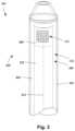
- FIGS. 6 A- 6 Cillustrate a portion of another embodiment of an IVUS catheter 602 with an integrated pullback arrangement.
- the catheterincludes a pullback slider arrangement 150 disposed between the distal section 110 and proximal extension 114 of the IVUS catheter.
- the proximal extension 114includes a proximal driveshaft 152 disposed within a proximal sheath 156 .
- the distal section 110includes a distal driveshaft 154 disposed in a distal sheath 158 .
- the proximal and distal driveshafts 152 , 154are coupled together.
- the proximal and distal driveshafts 152 , 154are coupled together within the pullback slider arrangement 150 using an optional intermediate driveshaft 153 (such as a hypotube).
- the pullback slider arrangement 150includes a housing 160 defining a slot 166 through the housing, a coupler 162 within the housing, and a slider handle 164 attached to the coupler and extending out of the housing.
- the coupler 162is coupled to one or both of the proximal or distal driveshafts 152 , 154 to move the driveshafts 152 , 154 while still allowing the driveshafts 152 , 154 to rotate within the coupler and housing 160 .
- the coupler 162may be attached to the proximal sheath 156 as illustrated in FIG. 6 C , and may include bearings or other suitable components for coupling to one or both of the driveshafts.
- the distal driveshaft 154By manually moving the slider handle 164 along the slot 166 in the housing, the distal driveshaft 154 (and the imaging device attached to the distal end of the driveshaft) is moved.
- a pullback procedurecan be performed by pulling the slider handle 164 along the slot 166 away from the distal section 110 of the catheter.
- the distal section 110can be flushed with sterile saline via a port 124 on the pullback slider arrangement 150 or distal section 110 .
- the housing 160which optionally contains a seal 125 to allow flushing without leakage of the saline.
- the slider handle 164 or housing 160may also incorporate one or more control buttons 132 , 134 .
- the control buttons 132 , 134may be operated during pullback to individually control functions such as “imaging start/stop”, “pullback recording start/stop”, “zero position”, or “place bookmark”.
- Pullback position measurement for the catheter 602may be accomplished using any suitable sensor and method of measurement. It will also be understood the sensors and methods described below can also be incorporated into the catheter 102 of FIGS. 4 and 5 .
- FIG. 9illustrates one embodiment of a capacitive sensor 136 that includes a top plate 180 and a bottom plate 182 that overlap over a distance defined by the position of the coupler 162 to form a variable capacitor. Excess length of the top plate 180 is taken up on a roller 184 (for example, a spring loaded or “windowshade” roller). This configuration produces a capacitance that varies with pullback position.
- Conductors 172 from the sensorcan be coupled to the imaging module 106 ( FIG. 1 ) and may be separate from the proximal extension 114 or run along or within the sheath 156 of the proximal extension 114 or in any other suitable arrangement. Again, as with the resistive sensor, a geared rotary variable capacitor could also be used.
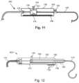
- FIG. 10illustrate one embodiment of an inductive sensor 136 that includes a coil 186 around a portion of the distal sheath 158 ( FIG. 6 C ) with a highly magnetic material 188 embedded in a portion of the rotating driveshaft 153 , 154 ( FIG. 6 C ) or a rotating sheath (not shown) on the driveshaft.
- the inductance of coil 186would vary as the magnetic material 188 is slid in or out of the sheath 158 .
- the inductancevaries in a predictable way with the overlap distance between the coil 186 and magnetic material 188 .
- Conductors 172 from the sensorcan be coupled to the imaging module 106 ( FIG.
- Capacitive and inductive sensorsmay be operated at some RF frequency (for example, about 10 to 100 MHz) for purposes of measuring their position-variable capacitance or inductance values.
- RF frequencyfor example, about 10 to 100 MHz
- the ultrasound transmitting and receiving electronicsare used to interrogate the sensor.
- a variable inductance sensorcould be coupled in parallel to a fixed capacitor and then the combination placed in parallel with the transducer's RF transmission line. If the resonant frequency of the sensor is designed to be far from the transducer frequency (say, using a 10 MHz sensor with a 40 MHz transducer) then the sensor can be interrogated by issuing a carefully designed transmit pulse between imaging periods.
Landscapes
- Health & Medical Sciences (AREA)
- Life Sciences & Earth Sciences (AREA)
- Engineering & Computer Science (AREA)
- Medical Informatics (AREA)
- Surgery (AREA)
- Pathology (AREA)
- Radiology & Medical Imaging (AREA)
- Biophysics (AREA)
- Biomedical Technology (AREA)
- Heart & Thoracic Surgery (AREA)
- Physics & Mathematics (AREA)
- Molecular Biology (AREA)
- Nuclear Medicine, Radiotherapy & Molecular Imaging (AREA)
- Animal Behavior & Ethology (AREA)
- General Health & Medical Sciences (AREA)
- Public Health (AREA)
- Veterinary Medicine (AREA)
- Gynecology & Obstetrics (AREA)
- Vascular Medicine (AREA)
- Ultra Sonic Daignosis Equipment (AREA)
- Computer Vision & Pattern Recognition (AREA)
Abstract
Description
Claims (10)
Priority Applications (2)
| Application Number | Priority Date | Filing Date | Title |
|---|---|---|---|
| US16/717,920US12343200B2 (en) | 2015-10-09 | 2019-12-17 | Intravascular ultrasound systems, catheters, and methods with a manual pullback arrangement |
| US19/077,171US20250204887A1 (en) | 2015-10-09 | 2025-03-12 | Intravascular ultrasound systems, catheters, and methods with a manual pullback arrangement |
Applications Claiming Priority (3)
| Application Number | Priority Date | Filing Date | Title |
|---|---|---|---|
| US201562239736P | 2015-10-09 | 2015-10-09 | |
| US15/285,342US20170164925A1 (en) | 2015-10-09 | 2016-10-04 | Intravascular ultrasound systems, catheters, and methods with a manual pullback arrangement |
| US16/717,920US12343200B2 (en) | 2015-10-09 | 2019-12-17 | Intravascular ultrasound systems, catheters, and methods with a manual pullback arrangement |
Related Parent Applications (1)
| Application Number | Title | Priority Date | Filing Date |
|---|---|---|---|
| US15/285,342DivisionUS20170164925A1 (en) | 2015-10-09 | 2016-10-04 | Intravascular ultrasound systems, catheters, and methods with a manual pullback arrangement |
Related Child Applications (1)
| Application Number | Title | Priority Date | Filing Date |
|---|---|---|---|
| US19/077,171ContinuationUS20250204887A1 (en) | 2015-10-09 | 2025-03-12 | Intravascular ultrasound systems, catheters, and methods with a manual pullback arrangement |
Publications (2)
| Publication Number | Publication Date |
|---|---|
| US20200121280A1 US20200121280A1 (en) | 2020-04-23 |
| US12343200B2true US12343200B2 (en) | 2025-07-01 |
Family
ID=57137308
Family Applications (3)
| Application Number | Title | Priority Date | Filing Date |
|---|---|---|---|
| US15/285,342AbandonedUS20170164925A1 (en) | 2015-10-09 | 2016-10-04 | Intravascular ultrasound systems, catheters, and methods with a manual pullback arrangement |
| US16/717,920Active2037-12-18US12343200B2 (en) | 2015-10-09 | 2019-12-17 | Intravascular ultrasound systems, catheters, and methods with a manual pullback arrangement |
| US19/077,171PendingUS20250204887A1 (en) | 2015-10-09 | 2025-03-12 | Intravascular ultrasound systems, catheters, and methods with a manual pullback arrangement |
Family Applications Before (1)
| Application Number | Title | Priority Date | Filing Date |
|---|---|---|---|
| US15/285,342AbandonedUS20170164925A1 (en) | 2015-10-09 | 2016-10-04 | Intravascular ultrasound systems, catheters, and methods with a manual pullback arrangement |
Family Applications After (1)
| Application Number | Title | Priority Date | Filing Date |
|---|---|---|---|
| US19/077,171PendingUS20250204887A1 (en) | 2015-10-09 | 2025-03-12 | Intravascular ultrasound systems, catheters, and methods with a manual pullback arrangement |
Country Status (4)
| Country | Link |
|---|---|
| US (3) | US20170164925A1 (en) |
| EP (2) | EP3316790B1 (en) |
| JP (1) | JP6626192B2 (en) |
| WO (1) | WO2017062371A1 (en) |
Families Citing this family (29)
| Publication number | Priority date | Publication date | Assignee | Title |
|---|---|---|---|---|
| US12239371B2 (en)* | 2018-08-09 | 2025-03-04 | Koninklijke Philips N.V. | Treatment mode selection systems and laser catheter systems including same |
| JP7147079B2 (en)* | 2019-05-17 | 2022-10-04 | ボストン サイエンティフィック サイムド,インコーポレイテッド | Medical imaging device and system |
| CN110141273A (en)* | 2019-05-24 | 2019-08-20 | 中国科学院苏州生物医学工程技术研究所 | Ultrasound equipment with handheld interventional probe |
| CN110507365A (en)* | 2019-10-08 | 2019-11-29 | 深圳开立生物医疗科技股份有限公司 | A kind of IVUS withdraws system and method |
| CN111110281B (en)* | 2020-01-20 | 2025-05-27 | 中国科学院苏州生物医学工程技术研究所 | Interventional 3D Ultrasound Imaging Device |
| US20210244382A1 (en) | 2020-02-12 | 2021-08-12 | Boston Scientific Scimed, Inc. | Imaging medical device systems with a bubble-reducing member |
| US11241196B2 (en) | 2020-03-20 | 2022-02-08 | Xenter, Inc. | Signal conducting device for concurrent power and data transfer to and from un-wired sensors attached to a medical device |
| JP7538856B2 (en)* | 2020-03-30 | 2024-08-22 | テルモ株式会社 | Drive unit, diagnostic imaging device and operation method |
| US12087000B2 (en) | 2021-03-05 | 2024-09-10 | Boston Scientific Scimed, Inc. | Systems and methods for vascular image co-registration |
| US11696793B2 (en)* | 2021-03-19 | 2023-07-11 | Crossfire Medical Inc | Vascular ablation |
| EP4346618A1 (en) | 2021-06-04 | 2024-04-10 | Boston Scientific Scimed Inc. | Imaging catheter with support member |
| EP4452080A1 (en) | 2021-12-31 | 2024-10-30 | Boston Scientific Scimed, Inc. | Systems and methods for vascular image co-registration |
| AU2023241636B2 (en) | 2022-03-29 | 2025-08-21 | Boston Scientific Scimed, Inc. | Telescoping catheter |
| US20230309835A1 (en) | 2022-03-30 | 2023-10-05 | Boston Scientific Scimed, Inc. | Systems and methods for vascular image co-registration |
| WO2023215558A1 (en) | 2022-05-06 | 2023-11-09 | Boston Scientific Scimed, Inc. | Intravascular imaging devices |
| US20240149020A1 (en) | 2022-11-04 | 2024-05-09 | Controlled Delivery Systems, Inc. | Catheters for the aspiration controlled delivery of closure agents |
| EP4611658A1 (en) | 2022-11-04 | 2025-09-10 | Solvein Inc. | Catheters and related methods for aspiration and controlled delivery of closure agents |
| CN118121235A (en) | 2022-12-01 | 2024-06-04 | 波士顿科学国际有限公司 | Intravascular imaging device |
| US20240285912A1 (en)* | 2023-02-27 | 2024-08-29 | Boston Scientific Scimed, Inc. | Intravascular Imaging Catheter |
| WO2024202461A1 (en)* | 2023-03-29 | 2024-10-03 | テルモ株式会社 | Diagnostic imaging device, diagnostic imaging system, catheter for diagnostic imaging, and catheter unit |
| WO2024206888A1 (en) | 2023-03-29 | 2024-10-03 | Boston Scientific Scimed, Inc. | Hybrid connector for intravascular imaging devices |
| AU2024268427A1 (en)* | 2023-05-05 | 2025-10-09 | Nuevosono Inc. | Wireless pullback distance sensor for ivus systems |
| WO2025038622A1 (en) | 2023-08-17 | 2025-02-20 | Boston Scientific Scimed, Inc. | Intravascular ultrasound catheter |
| US20250072863A1 (en) | 2023-08-30 | 2025-03-06 | Boston Scientific Scimed, Inc. | Intravascular Ultrasound Catheter |
| US20250186019A1 (en) | 2023-12-11 | 2025-06-12 | Boston Scientific Scimed, Inc. | Intravascular imaging catheter |
| US20250195035A1 (en) | 2023-12-13 | 2025-06-19 | Boston Scientific Scimed, Inc. | Intravascular imaging catheter |
| US20250221623A1 (en) | 2024-01-08 | 2025-07-10 | Boston Scientific Scimed, Inc. | Intravascular imaging catheter |
| WO2025151439A1 (en) | 2024-01-08 | 2025-07-17 | Boston Scientific Scimed, Inc. | Intravascular imaging catheter |
| US20250228459A1 (en) | 2024-01-15 | 2025-07-17 | Boston Scientific Scimed, Inc. | Intravascular imaging catheter |
Citations (95)
| Publication number | Priority date | Publication date | Assignee | Title |
|---|---|---|---|---|
| US3838688A (en) | 1971-12-28 | 1974-10-01 | Int Paper Co | Catheter advances with clutch |
| FR2543817A1 (en) | 1983-04-06 | 1984-10-12 | Rabelais Univ Francois | ENDOSCOPIC ULTRASOUND SCANNING AND ULTRASONIC ULTRASOUND PROBE |
| EP0163502A2 (en) | 1984-05-30 | 1985-12-04 | Devices For Vascular Intervention Inc. | Atherectomy device |
| US4593699A (en) | 1983-06-13 | 1986-06-10 | Poncy Richard P | Sterile cover for intraoperative ultrasonic diagnostic devices and method and kit for providing same |
| EP0244058A1 (en) | 1986-02-28 | 1987-11-04 | Devices For Vascular Intervention, Inc. | Motor drive unit for use with an atherectomy catheter device |
| US4708125A (en) | 1985-07-24 | 1987-11-24 | Messrs. Karl Storz Gmbh & Co. | Apparatus for controlling a probe of an endoscopy device |
| EP0266858A1 (en) | 1986-10-06 | 1988-05-11 | GV Medical, Inc. | Adjustable control apparatus for optical fibers |
| US4771774A (en) | 1986-02-28 | 1988-09-20 | Devices For Vascular Intervention, Inc. | Motor drive unit |
| US4794931A (en) | 1986-02-28 | 1989-01-03 | Cardiovascular Imaging Systems, Inc. | Catheter apparatus, system and method for intravascular two-dimensional ultrasonography |
| US4802487A (en) | 1987-03-26 | 1989-02-07 | Washington Research Foundation | Endoscopically deliverable ultrasound imaging system |
| US4841977A (en) | 1987-05-26 | 1989-06-27 | Inter Therapy, Inc. | Ultra-thin acoustic transducer and balloon catheter using same in imaging array subassembly |
| US4870970A (en) | 1986-08-12 | 1989-10-03 | Fulmer Limited | Ultrasonic investigation apparatus |
| WO1990001300A1 (en) | 1988-08-05 | 1990-02-22 | Sonic Needle Corporation | Ultrasonic device for applying cavitation forces |
| US4917097A (en) | 1987-10-27 | 1990-04-17 | Endosonics Corporation | Apparatus and method for imaging small cavities |
| US4951677A (en) | 1988-03-21 | 1990-08-28 | Prutech Research And Development Partnership Ii | Acoustic imaging catheter and the like |
| EP0397459A1 (en) | 1989-05-08 | 1990-11-14 | Medtronic, Inc. | Catheter |
| US5000185A (en) | 1986-02-28 | 1991-03-19 | Cardiovascular Imaging Systems, Inc. | Method for intravascular two-dimensional ultrasonography and recanalization |
| US5002553A (en) | 1984-05-14 | 1991-03-26 | Surgical Systems & Instruments, Inc. | Atherectomy system with a clutch |
| US5019189A (en) | 1989-04-13 | 1991-05-28 | Kawasaki Steel Corporation | Steel pipe and a method for welding thereof and pipeline resistant to carbon dioxide corrosion |
| US5048529A (en) | 1988-09-01 | 1991-09-17 | Elscint Ltd. | Ultrasonic transducer probe |
| WO1991015154A1 (en) | 1990-04-06 | 1991-10-17 | Technomed International | Process for automatically measuring the volume of a tumour or of a gland, in particular the prostate, measurement device, process and apparatus using same |
| WO1992003095A1 (en) | 1990-08-21 | 1992-03-05 | Boston Scientific Corporation | Acoustic imaging catheter and the like |
| US5105819A (en) | 1988-09-01 | 1992-04-21 | Kon-Tron Elektronik AG | Ultrasound endoscope device |
| US5107844A (en) | 1989-04-06 | 1992-04-28 | Olympus Optical Co., Ltd. | Ultrasonic observing apparatus |
| US5115814A (en) | 1989-08-18 | 1992-05-26 | Intertherapy, Inc. | Intravascular ultrasonic imaging probe and methods of using same |
| US5125410A (en) | 1989-10-13 | 1992-06-30 | Olympus Optical Co., Ltd. | Integrated ultrasonic diagnosis device utilizing intra-blood-vessel probe |
| WO1992019930A1 (en) | 1991-04-29 | 1992-11-12 | Massachusetts Institute Of Technology | Method and apparatus for optical imaging and measurement |
| US5203338A (en) | 1990-12-17 | 1993-04-20 | Cardiovascular Imaging Systems, Inc. | Vascular catheter having low-profile distal end |
| US5211176A (en) | 1990-11-30 | 1993-05-18 | Fuji Photo Optical Co., Ltd. | Ultrasound examination system |
| WO1993016642A1 (en) | 1992-02-21 | 1993-09-02 | Boston Scientific Corporation | Ultrasound imaging guidewire |
| WO1994000052A1 (en) | 1992-06-30 | 1994-01-06 | Cardiovascular Imaging Systems, Inc. | Automated position translator for ultrasonic imaging probe |
| WO1994011038A1 (en) | 1992-11-13 | 1994-05-26 | Cardiovascular Imaging Systems, Inc. | Intravascular catheter |
| US5318576A (en) | 1992-12-16 | 1994-06-07 | Plassche Jr Walter M | Endovascular surgery systems |
| DE4344312A1 (en) | 1992-12-24 | 1994-07-14 | London Health Ass | Ultrasonic scanner for medical diagnostics of eye or prostate |
| US5358485A (en) | 1992-01-13 | 1994-10-25 | Schneider (Usa) Inc. | Cutter for atherectomy catheter |
| US5360432A (en) | 1992-10-16 | 1994-11-01 | Shturman Cardiology Systems, Inc. | Abrasive drive shaft device for directional rotational atherectomy |
| US5366464A (en) | 1993-07-22 | 1994-11-22 | Belknap John C | Atherectomy catheter device |
| EP0626152A1 (en) | 1993-05-28 | 1994-11-30 | Acuson Corporation | Compact rotationally steerable ultrasound transducer |
| US5373849A (en) | 1993-01-19 | 1994-12-20 | Cardiovascular Imaging Systems, Inc. | Forward viewing imaging catheter |
| US5383460A (en) | 1992-10-05 | 1995-01-24 | Cardiovascular Imaging Systems, Inc. | Method and apparatus for ultrasound imaging and atherectomy |
| US5398690A (en) | 1994-08-03 | 1995-03-21 | Batten; Bobby G. | Slaved biopsy device, analysis apparatus, and process |
| US5488955A (en) | 1992-07-22 | 1996-02-06 | Hewlett Packard Company | Magnetostriction transducer and an intraoperative probe for acoustic imaging |
| US5490859A (en) | 1992-11-13 | 1996-02-13 | Scimed Life Systems, Inc. | Expandable intravascular occlusion material removal devices and methods of use |
| US5497776A (en) | 1993-08-05 | 1996-03-12 | Olympus Optical Co., Ltd. | Ultrasonic image diagnosing apparatus for displaying three-dimensional image |
| US5546947A (en) | 1993-09-30 | 1996-08-20 | Terumo Kabushiki Kaisha | Ultrasonic endoprobe |
| US5551432A (en) | 1995-06-19 | 1996-09-03 | New York Eye & Ear Infirmary | Scanning control system for ultrasound biomicroscopy |
| US5554163A (en) | 1995-04-27 | 1996-09-10 | Shturman Cardiology Systems, Inc. | Atherectomy device |
| US5569179A (en) | 1995-10-26 | 1996-10-29 | Medelex, Inc. | Acoustic catheter with magnetic drive |
| WO1997032182A1 (en) | 1996-02-27 | 1997-09-04 | Massachusetts Institute Of Technology | Method and apparatus for performing optical measurements using a fiber optic imaging guidewire, catheter or endoscope |
| DE19619774A1 (en) | 1996-05-15 | 1997-11-20 | Promed Gmbh | Processing device, esp. with cutter or abrasive tool for polishing surfaces |
| JPH1066696A (en) | 1996-08-28 | 1998-03-10 | Terumo Corp | Medial equipment and torque transmitter |
| US5762599A (en) | 1994-05-02 | 1998-06-09 | Influence Medical Technologies, Ltd. | Magnetically-coupled implantable medical devices |
| US5797858A (en) | 1997-03-14 | 1998-08-25 | Hewlett-Packard Company | Spooling pullback for catheter imaging and therapy cores |
| US5827313A (en) | 1996-09-27 | 1998-10-27 | Boston Scientific Corporation | Device for controlled longitudinal movement of an operative element within a catheter sheath and method |
| US5833616A (en) | 1996-08-30 | 1998-11-10 | The Whitaker Corporation | Navigable probe and rotating motor control apparatus |
| US5865748A (en) | 1998-01-16 | 1999-02-02 | Guidant Corporation | Guided directional coronary atherectomy distal linear encoder |
| US5897567A (en) | 1993-04-29 | 1999-04-27 | Scimed Life Systems, Inc. | Expandable intravascular occlusion material removal devices and methods of use |
| US5932035A (en) | 1993-10-29 | 1999-08-03 | Boston Scientific Corporation | Drive shaft for acoustic imaging catheters and flexible catheters |
| US5957941A (en) | 1996-09-27 | 1999-09-28 | Boston Scientific Corporation | Catheter system and drive assembly thereof |
| US5967984A (en)* | 1995-06-30 | 1999-10-19 | Boston Scientific Corporation | Ultrasound imaging catheter with a cutting element |
| US6004271A (en) | 1998-05-07 | 1999-12-21 | Boston Scientific Corporation | Combined motor drive and automated longitudinal position translator for ultrasonic imaging system |
| US6319227B1 (en) | 1998-08-05 | 2001-11-20 | Scimed Life Systems, Inc. | Automatic/manual longitudinal position translator and rotary drive system for catheters |
| US6398755B1 (en) | 1998-10-06 | 2002-06-04 | Scimed Life Systems, Inc. | Driveable catheter system |
| US6413222B1 (en) | 2000-04-13 | 2002-07-02 | Boston Scientific Corporation | Catheter drive shaft clutch |
| US6454717B1 (en) | 2000-04-13 | 2002-09-24 | Scimed Life Systems, Inc. | Concentric catheter drive shaft clutch |
| US6475224B1 (en) | 2000-04-13 | 2002-11-05 | Scimed Life Systems, Inc. | Catheter drive shaft spring clutch |
| US20020188225A1 (en)* | 1998-10-23 | 2002-12-12 | White David A. | System and method for intraluminal imaging |
| US6517528B1 (en)* | 2000-04-13 | 2003-02-11 | Scimed Life Systems, Inc. | Magnetic catheter drive shaft clutch |
| US20030187369A1 (en)* | 2002-03-28 | 2003-10-02 | Lewis Stephen B. | Optical pullback sensor for measuring linear displacement of a catheter or other elongate member |
| US6945938B2 (en) | 1998-10-02 | 2005-09-20 | Boston Scientific Limited | Systems and methods for evaluating objects with an ultrasound image |
| US7004911B1 (en) | 2003-02-24 | 2006-02-28 | Hosheng Tu | Optical thermal mapping for detecting vulnerable plaque |
| US20060052700A1 (en) | 2004-09-08 | 2006-03-09 | Radi Medical Systems Ab | Pressure measurement system |
| US20060100522A1 (en) | 2004-11-08 | 2006-05-11 | Scimed Life Systems, Inc. | Piezocomposite transducers |
| US20060106320A1 (en) | 2001-07-16 | 2006-05-18 | Scimed Life Systems, Inc. | Electronically scanned optical coherence tomography with frequency modulated signals |
| US20060173350A1 (en) | 2005-01-11 | 2006-08-03 | Scimed Life Systems, Inc. | Systems and methods for three dimensional imaging with an orientation adjustable array |
| US20060253028A1 (en) | 2005-04-20 | 2006-11-09 | Scimed Life Systems, Inc. | Multiple transducer configurations for medical ultrasound imaging |
| US20070000498A1 (en) | 2005-06-23 | 2007-01-04 | Glynn Timothy K | Pleated bag for interventional pullback systems |
| US20070016054A1 (en) | 2005-07-01 | 2007-01-18 | Scimed Life Systems, Inc. | Medical imaging device having a forward looking flow detector |
| US20070038111A1 (en) | 2005-08-12 | 2007-02-15 | Scimed Life Systems, Inc. | Micromachined imaging transducer |
| US7246959B2 (en) | 2004-04-28 | 2007-07-24 | Funai Electric Co., Ltd. | Image formation apparatus and sublimation printer |
| WO2007103726A2 (en) | 2006-03-01 | 2007-09-13 | The Brigham And Women's Hospital, Inc. | Artery imaging system |
| US7306561B2 (en) | 2004-09-02 | 2007-12-11 | Scimed Life Systems, Inc. | Systems and methods for automatic time-gain compensation in an ultrasound imaging system |
| US20080021275A1 (en) | 2006-01-19 | 2008-01-24 | The General Hospital Corporation | Methods and systems for optical imaging or epithelial luminal organs by beam scanning thereof |
| US20080051660A1 (en) | 2004-01-16 | 2008-02-28 | The University Of Houston System | Methods and apparatuses for medical imaging |
| US20080146942A1 (en) | 2006-12-13 | 2008-06-19 | Ep Medsystems, Inc. | Catheter Position Tracking Methods Using Fluoroscopy and Rotational Sensors |
| US20080167560A1 (en) | 2007-01-09 | 2008-07-10 | Peter Thornton | Self-Aligning IVUS Catheter Rotational Core Connector |
| US20090156941A1 (en)* | 2007-12-17 | 2009-06-18 | Silicon Valley Medical Instruments, Inc. | Telescope for an imaging catheter |
| US20090234319A1 (en) | 2005-06-03 | 2009-09-17 | Innovacell Biotechnologie Gmbh | Injection device and method |
| US20090270737A1 (en) | 2008-02-28 | 2009-10-29 | Boston Scientific Scimed, Inc | Imaging catheter |
| US20090318003A1 (en)* | 2008-06-18 | 2009-12-24 | Volcano Corporation | Axial multi-wire barrel connector for interconnecting a controller console to catheter including a distally mounted ultrasound transducer assembly |
| US20100249588A1 (en) | 2009-03-31 | 2010-09-30 | Boston Scientific Scimed, Inc. | Systems and methods for making and using intravascular imaging systems with multiple pullback rates |
| US20140142436A1 (en)* | 2012-11-19 | 2014-05-22 | Christopher Hutchins | Interface Devices, Systems and Methods for Multimodal Probes |
| US20140180142A1 (en) | 2012-12-21 | 2014-06-26 | Volcano Corporation | Pressure-Sensing Intravascular Devices, Systems, and Methods |
| WO2014134275A2 (en)* | 2013-02-27 | 2014-09-04 | The George Washington University | Ultrasound assisted catheter placement system |
| US20150182190A1 (en)* | 2013-12-30 | 2015-07-02 | Acist Medical Systems, Inc. | Position sensing in intravascular imaging |
Family Cites Families (2)
| Publication number | Priority date | Publication date | Assignee | Title |
|---|---|---|---|---|
| US6478743B2 (en)* | 2001-03-16 | 2002-11-12 | Ge Medical Systems Global Technology Company, Llc | Transesophageal ultrasound probe with imaging element position sensor in scanhead |
| JP2004298352A (en)* | 2003-03-31 | 2004-10-28 | Fuji Photo Optical Co Ltd | Ultrasonograph |
- 2016
- 2016-10-04EPEP16781968.9Apatent/EP3316790B1/enactiveActive
- 2016-10-04USUS15/285,342patent/US20170164925A1/ennot_activeAbandoned
- 2016-10-04EPEP24201940.4Apatent/EP4505946A3/enactivePending
- 2016-10-04WOPCT/US2016/055358patent/WO2017062371A1/ennot_activeCeased
- 2016-10-04JPJP2018510728Apatent/JP6626192B2/enactiveActive
- 2019
- 2019-12-17USUS16/717,920patent/US12343200B2/enactiveActive
- 2025
- 2025-03-12USUS19/077,171patent/US20250204887A1/enactivePending
Patent Citations (108)
| Publication number | Priority date | Publication date | Assignee | Title |
|---|---|---|---|---|
| US3838688A (en) | 1971-12-28 | 1974-10-01 | Int Paper Co | Catheter advances with clutch |
| FR2543817A1 (en) | 1983-04-06 | 1984-10-12 | Rabelais Univ Francois | ENDOSCOPIC ULTRASOUND SCANNING AND ULTRASONIC ULTRASOUND PROBE |
| US4593699A (en) | 1983-06-13 | 1986-06-10 | Poncy Richard P | Sterile cover for intraoperative ultrasonic diagnostic devices and method and kit for providing same |
| US5002553A (en) | 1984-05-14 | 1991-03-26 | Surgical Systems & Instruments, Inc. | Atherectomy system with a clutch |
| EP0163502A2 (en) | 1984-05-30 | 1985-12-04 | Devices For Vascular Intervention Inc. | Atherectomy device |
| US4708125A (en) | 1985-07-24 | 1987-11-24 | Messrs. Karl Storz Gmbh & Co. | Apparatus for controlling a probe of an endoscopy device |
| US5000185A (en) | 1986-02-28 | 1991-03-19 | Cardiovascular Imaging Systems, Inc. | Method for intravascular two-dimensional ultrasonography and recanalization |
| US4771774A (en) | 1986-02-28 | 1988-09-20 | Devices For Vascular Intervention, Inc. | Motor drive unit |
| US4794931A (en) | 1986-02-28 | 1989-01-03 | Cardiovascular Imaging Systems, Inc. | Catheter apparatus, system and method for intravascular two-dimensional ultrasonography |
| US5651364A (en) | 1986-02-28 | 1997-07-29 | Cardiovascular Imaging Systems, Inc. | Method and apparatus for intravascular |
| EP0244058A1 (en) | 1986-02-28 | 1987-11-04 | Devices For Vascular Intervention, Inc. | Motor drive unit for use with an atherectomy catheter device |
| US5865178A (en) | 1986-02-28 | 1999-02-02 | Cardiovascular Imaging System, Inc. | Method and apparatus for intravascular ultrasonography |
| US4870970A (en) | 1986-08-12 | 1989-10-03 | Fulmer Limited | Ultrasonic investigation apparatus |
| EP0266858A1 (en) | 1986-10-06 | 1988-05-11 | GV Medical, Inc. | Adjustable control apparatus for optical fibers |
| US4802487A (en) | 1987-03-26 | 1989-02-07 | Washington Research Foundation | Endoscopically deliverable ultrasound imaging system |
| US4841977A (en) | 1987-05-26 | 1989-06-27 | Inter Therapy, Inc. | Ultra-thin acoustic transducer and balloon catheter using same in imaging array subassembly |
| US4917097A (en) | 1987-10-27 | 1990-04-17 | Endosonics Corporation | Apparatus and method for imaging small cavities |
| US4951677A (en) | 1988-03-21 | 1990-08-28 | Prutech Research And Development Partnership Ii | Acoustic imaging catheter and the like |
| WO1990001300A1 (en) | 1988-08-05 | 1990-02-22 | Sonic Needle Corporation | Ultrasonic device for applying cavitation forces |
| US5048529A (en) | 1988-09-01 | 1991-09-17 | Elscint Ltd. | Ultrasonic transducer probe |
| US5105819A (en) | 1988-09-01 | 1992-04-21 | Kon-Tron Elektronik AG | Ultrasound endoscope device |
| US5107844A (en) | 1989-04-06 | 1992-04-28 | Olympus Optical Co., Ltd. | Ultrasonic observing apparatus |
| US5019189A (en) | 1989-04-13 | 1991-05-28 | Kawasaki Steel Corporation | Steel pipe and a method for welding thereof and pipeline resistant to carbon dioxide corrosion |
| EP0397459A1 (en) | 1989-05-08 | 1990-11-14 | Medtronic, Inc. | Catheter |
| US5115814A (en) | 1989-08-18 | 1992-05-26 | Intertherapy, Inc. | Intravascular ultrasonic imaging probe and methods of using same |
| US5125410A (en) | 1989-10-13 | 1992-06-30 | Olympus Optical Co., Ltd. | Integrated ultrasonic diagnosis device utilizing intra-blood-vessel probe |
| WO1991015154A1 (en) | 1990-04-06 | 1991-10-17 | Technomed International | Process for automatically measuring the volume of a tumour or of a gland, in particular the prostate, measurement device, process and apparatus using same |
| US5178148A (en) | 1990-04-06 | 1993-01-12 | Technomed International | Method of automatically measuring the volume of a tumor or of a gland, in particular the prostate, a measuring device, and a method and apparatus constituting and application thereof |
| WO1992003095A1 (en) | 1990-08-21 | 1992-03-05 | Boston Scientific Corporation | Acoustic imaging catheter and the like |
| US5211176A (en) | 1990-11-30 | 1993-05-18 | Fuji Photo Optical Co., Ltd. | Ultrasound examination system |
| US5203338A (en) | 1990-12-17 | 1993-04-20 | Cardiovascular Imaging Systems, Inc. | Vascular catheter having low-profile distal end |
| US5321501A (en) | 1991-04-29 | 1994-06-14 | Massachusetts Institute Of Technology | Method and apparatus for optical imaging with means for controlling the longitudinal range of the sample |
| WO1992019930A1 (en) | 1991-04-29 | 1992-11-12 | Massachusetts Institute Of Technology | Method and apparatus for optical imaging and measurement |
| US5358485A (en) | 1992-01-13 | 1994-10-25 | Schneider (Usa) Inc. | Cutter for atherectomy catheter |
| WO1993016642A1 (en) | 1992-02-21 | 1993-09-02 | Boston Scientific Corporation | Ultrasound imaging guidewire |
| WO1994000052A1 (en) | 1992-06-30 | 1994-01-06 | Cardiovascular Imaging Systems, Inc. | Automated position translator for ultrasonic imaging probe |
| US5592942A (en) | 1992-06-30 | 1997-01-14 | Cardiovascular Imaging Systems, Inc. | Automated longitudinal position translator for ultrasonic imaging probes, and methods of using same |
| US6193736B1 (en) | 1992-06-30 | 2001-02-27 | Cardiovascular Imaging Systems, Inc. | Automated longitudinal position translator for ultrasonic imaging probes and methods of using same |
| US5759153A (en) | 1992-06-30 | 1998-06-02 | Cardiovascular Imaging Systems, Inc. | Automated longitudinal position translator for ultrasonic imaging probes, and methods of using same |
| US5485846A (en) | 1992-06-30 | 1996-01-23 | Cardiovascular Imaging Systems, Inc. | Automated longitudinal position translator for ultrasonic imaging probes, and methods of using same |
| US6013030A (en) | 1992-06-30 | 2000-01-11 | Cardiovascular Imaging Systems, Inc. | Automated longitudinal position translator for ultrasonic imaging probes, and methods of using same |
| US5488955A (en) | 1992-07-22 | 1996-02-06 | Hewlett Packard Company | Magnetostriction transducer and an intraoperative probe for acoustic imaging |
| US5383460A (en) | 1992-10-05 | 1995-01-24 | Cardiovascular Imaging Systems, Inc. | Method and apparatus for ultrasound imaging and atherectomy |
| US5360432A (en) | 1992-10-16 | 1994-11-01 | Shturman Cardiology Systems, Inc. | Abrasive drive shaft device for directional rotational atherectomy |
| WO1994011038A1 (en) | 1992-11-13 | 1994-05-26 | Cardiovascular Imaging Systems, Inc. | Intravascular catheter |
| US5490859A (en) | 1992-11-13 | 1996-02-13 | Scimed Life Systems, Inc. | Expandable intravascular occlusion material removal devices and methods of use |
| US5318576A (en) | 1992-12-16 | 1994-06-07 | Plassche Jr Walter M | Endovascular surgery systems |
| DE4344312A1 (en) | 1992-12-24 | 1994-07-14 | London Health Ass | Ultrasonic scanner for medical diagnostics of eye or prostate |
| US5373849A (en) | 1993-01-19 | 1994-12-20 | Cardiovascular Imaging Systems, Inc. | Forward viewing imaging catheter |
| US5897567A (en) | 1993-04-29 | 1999-04-27 | Scimed Life Systems, Inc. | Expandable intravascular occlusion material removal devices and methods of use |
| EP0626152A1 (en) | 1993-05-28 | 1994-11-30 | Acuson Corporation | Compact rotationally steerable ultrasound transducer |
| US5366464A (en) | 1993-07-22 | 1994-11-22 | Belknap John C | Atherectomy catheter device |
| US5497776A (en) | 1993-08-05 | 1996-03-12 | Olympus Optical Co., Ltd. | Ultrasonic image diagnosing apparatus for displaying three-dimensional image |
| US5546947A (en) | 1993-09-30 | 1996-08-20 | Terumo Kabushiki Kaisha | Ultrasonic endoprobe |
| US5932035A (en) | 1993-10-29 | 1999-08-03 | Boston Scientific Corporation | Drive shaft for acoustic imaging catheters and flexible catheters |
| US5762599A (en) | 1994-05-02 | 1998-06-09 | Influence Medical Technologies, Ltd. | Magnetically-coupled implantable medical devices |
| US5398690A (en) | 1994-08-03 | 1995-03-21 | Batten; Bobby G. | Slaved biopsy device, analysis apparatus, and process |
| US5554163A (en) | 1995-04-27 | 1996-09-10 | Shturman Cardiology Systems, Inc. | Atherectomy device |
| US5551432A (en) | 1995-06-19 | 1996-09-03 | New York Eye & Ear Infirmary | Scanning control system for ultrasound biomicroscopy |
| US5967984A (en)* | 1995-06-30 | 1999-10-19 | Boston Scientific Corporation | Ultrasound imaging catheter with a cutting element |
| US5569179A (en) | 1995-10-26 | 1996-10-29 | Medelex, Inc. | Acoustic catheter with magnetic drive |
| WO1997032182A1 (en) | 1996-02-27 | 1997-09-04 | Massachusetts Institute Of Technology | Method and apparatus for performing optical measurements using a fiber optic imaging guidewire, catheter or endoscope |
| DE19619774A1 (en) | 1996-05-15 | 1997-11-20 | Promed Gmbh | Processing device, esp. with cutter or abrasive tool for polishing surfaces |
| JPH1066696A (en) | 1996-08-28 | 1998-03-10 | Terumo Corp | Medial equipment and torque transmitter |
| US5833616A (en) | 1996-08-30 | 1998-11-10 | The Whitaker Corporation | Navigable probe and rotating motor control apparatus |
| US5957941A (en) | 1996-09-27 | 1999-09-28 | Boston Scientific Corporation | Catheter system and drive assembly thereof |
| US5827313A (en) | 1996-09-27 | 1998-10-27 | Boston Scientific Corporation | Device for controlled longitudinal movement of an operative element within a catheter sheath and method |
| US5797858A (en) | 1997-03-14 | 1998-08-25 | Hewlett-Packard Company | Spooling pullback for catheter imaging and therapy cores |
| US5865748A (en) | 1998-01-16 | 1999-02-02 | Guidant Corporation | Guided directional coronary atherectomy distal linear encoder |
| US6004271A (en) | 1998-05-07 | 1999-12-21 | Boston Scientific Corporation | Combined motor drive and automated longitudinal position translator for ultrasonic imaging system |
| EP1076513A1 (en) | 1998-05-07 | 2001-02-21 | SciMed Life Systems, Inc. | Combined motor drive and automated longitudinal position translator for ultrasonic imaging system |
| US6319227B1 (en) | 1998-08-05 | 2001-11-20 | Scimed Life Systems, Inc. | Automatic/manual longitudinal position translator and rotary drive system for catheters |
| US20050043618A1 (en)* | 1998-08-05 | 2005-02-24 | Scimed Life Systems, Inc. | Automatic/manual longitudinal position translator and rotary drive system for catheters |
| US6945938B2 (en) | 1998-10-02 | 2005-09-20 | Boston Scientific Limited | Systems and methods for evaluating objects with an ultrasound image |
| US6398755B1 (en) | 1998-10-06 | 2002-06-04 | Scimed Life Systems, Inc. | Driveable catheter system |
| US20060084911A1 (en)* | 1998-10-06 | 2006-04-20 | Boston Scientific Scimed, Inc. | Driveable catheter systems and methods |
| US20020188225A1 (en)* | 1998-10-23 | 2002-12-12 | White David A. | System and method for intraluminal imaging |
| US6413222B1 (en) | 2000-04-13 | 2002-07-02 | Boston Scientific Corporation | Catheter drive shaft clutch |
| US6454717B1 (en) | 2000-04-13 | 2002-09-24 | Scimed Life Systems, Inc. | Concentric catheter drive shaft clutch |
| US6475224B1 (en) | 2000-04-13 | 2002-11-05 | Scimed Life Systems, Inc. | Catheter drive shaft spring clutch |
| US6517528B1 (en)* | 2000-04-13 | 2003-02-11 | Scimed Life Systems, Inc. | Magnetic catheter drive shaft clutch |
| US20060106320A1 (en) | 2001-07-16 | 2006-05-18 | Scimed Life Systems, Inc. | Electronically scanned optical coherence tomography with frequency modulated signals |
| US20030187369A1 (en)* | 2002-03-28 | 2003-10-02 | Lewis Stephen B. | Optical pullback sensor for measuring linear displacement of a catheter or other elongate member |
| US7004911B1 (en) | 2003-02-24 | 2006-02-28 | Hosheng Tu | Optical thermal mapping for detecting vulnerable plaque |
| US20080051660A1 (en) | 2004-01-16 | 2008-02-28 | The University Of Houston System | Methods and apparatuses for medical imaging |
| US7246959B2 (en) | 2004-04-28 | 2007-07-24 | Funai Electric Co., Ltd. | Image formation apparatus and sublimation printer |
| US7306561B2 (en) | 2004-09-02 | 2007-12-11 | Scimed Life Systems, Inc. | Systems and methods for automatic time-gain compensation in an ultrasound imaging system |
| US20060052700A1 (en) | 2004-09-08 | 2006-03-09 | Radi Medical Systems Ab | Pressure measurement system |
| US20060100522A1 (en) | 2004-11-08 | 2006-05-11 | Scimed Life Systems, Inc. | Piezocomposite transducers |
| US20060173350A1 (en) | 2005-01-11 | 2006-08-03 | Scimed Life Systems, Inc. | Systems and methods for three dimensional imaging with an orientation adjustable array |
| US20060253028A1 (en) | 2005-04-20 | 2006-11-09 | Scimed Life Systems, Inc. | Multiple transducer configurations for medical ultrasound imaging |
| US20090234319A1 (en) | 2005-06-03 | 2009-09-17 | Innovacell Biotechnologie Gmbh | Injection device and method |
| US20070000498A1 (en) | 2005-06-23 | 2007-01-04 | Glynn Timothy K | Pleated bag for interventional pullback systems |
| US20070016054A1 (en) | 2005-07-01 | 2007-01-18 | Scimed Life Systems, Inc. | Medical imaging device having a forward looking flow detector |
| US20070038111A1 (en) | 2005-08-12 | 2007-02-15 | Scimed Life Systems, Inc. | Micromachined imaging transducer |
| US20080021275A1 (en) | 2006-01-19 | 2008-01-24 | The General Hospital Corporation | Methods and systems for optical imaging or epithelial luminal organs by beam scanning thereof |
| US20080004530A1 (en) | 2006-03-01 | 2008-01-03 | Brigham And Women's Hospital, Inc. | Artery imaging system |
| WO2007103726A2 (en) | 2006-03-01 | 2007-09-13 | The Brigham And Women's Hospital, Inc. | Artery imaging system |
| US20080146942A1 (en) | 2006-12-13 | 2008-06-19 | Ep Medsystems, Inc. | Catheter Position Tracking Methods Using Fluoroscopy and Rotational Sensors |
| US20080167560A1 (en) | 2007-01-09 | 2008-07-10 | Peter Thornton | Self-Aligning IVUS Catheter Rotational Core Connector |
| US20090156941A1 (en)* | 2007-12-17 | 2009-06-18 | Silicon Valley Medical Instruments, Inc. | Telescope for an imaging catheter |
| US20090270737A1 (en) | 2008-02-28 | 2009-10-29 | Boston Scientific Scimed, Inc | Imaging catheter |
| US20090318003A1 (en)* | 2008-06-18 | 2009-12-24 | Volcano Corporation | Axial multi-wire barrel connector for interconnecting a controller console to catheter including a distally mounted ultrasound transducer assembly |
| US20100249588A1 (en) | 2009-03-31 | 2010-09-30 | Boston Scientific Scimed, Inc. | Systems and methods for making and using intravascular imaging systems with multiple pullback rates |
| US20140142436A1 (en)* | 2012-11-19 | 2014-05-22 | Christopher Hutchins | Interface Devices, Systems and Methods for Multimodal Probes |
| US20140180142A1 (en) | 2012-12-21 | 2014-06-26 | Volcano Corporation | Pressure-Sensing Intravascular Devices, Systems, and Methods |
| WO2014134275A2 (en)* | 2013-02-27 | 2014-09-04 | The George Washington University | Ultrasound assisted catheter placement system |
| US20150182190A1 (en)* | 2013-12-30 | 2015-07-02 | Acist Medical Systems, Inc. | Position sensing in intravascular imaging |
Non-Patent Citations (2)
| Title |
|---|
| International Search Report and Written Opinion for International Application No. PCT/US2016/055358, mailed Mar. 15, 2017, 19 pages. |
| Les Schaevitz, "Finding the right sensor for linear displacement," Jul. 8, 2004, MachineDesign, pp. 1-14 (Year: 2004).* |
Also Published As
| Publication number | Publication date |
|---|---|
| WO2017062371A1 (en) | 2017-04-13 |
| JP2018525159A (en) | 2018-09-06 |
| US20200121280A1 (en) | 2020-04-23 |
| US20170164925A1 (en) | 2017-06-15 |
| JP6626192B2 (en) | 2019-12-25 |
| EP4505946A3 (en) | 2025-02-26 |
| US20250204887A1 (en) | 2025-06-26 |
| EP3316790A1 (en) | 2018-05-09 |
| EP4505946A2 (en) | 2025-02-12 |
| EP3316790B1 (en) | 2024-09-25 |
Similar Documents
| Publication | Publication Date | Title |
|---|---|---|
| US12343200B2 (en) | Intravascular ultrasound systems, catheters, and methods with a manual pullback arrangement | |
| JP7627243B2 (en) | Method for controlling the operation of an imaging system and system for acquiring images - Patents.com | |
| EP2413805B1 (en) | Intravascular imaging systems with multiple pullback rates | |
| US20120130242A1 (en) | Systems and methods for concurrently displaying a plurality of images using an intravascular ultrasound imaging system | |
| US20230157672A1 (en) | Intravascular ultrasound imaging and calcium detection methods | |
| US10512449B2 (en) | Intravascular device for vessel measurement and associated systems, devices, and methods | |
| EP3697315B1 (en) | Digital rotational patient interface module | |
| US20100179434A1 (en) | Systems and methods for making and using intravascular ultrasound systems with photo-acoustic imaging capabilities | |
| CN112512409A (en) | Intravascular imaging procedure-specific workflow guidance and associated devices, systems, and methods | |
| US20100179432A1 (en) | Systems and methods for making and using intravascular ultrasound systems with photo-acoustic imaging capabilities | |
| JP2016503679A (en) | Steerable intravascular device, and related devices, systems, and methods | |
| US20140163361A1 (en) | Combination Rotational and Phased-Array In Vivo Imaging Devices and Methods | |
| US20220287679A1 (en) | Disposable catheter with rotatable image array | |
| AU2014223201A1 (en) | Systems and methods for lumen border detection in intravascular ultrasound sequences | |
| CN111067574A (en) | System, catheter, drive unit and method for automatic catheter identification | |
| WO2016034977A1 (en) | Intravascular ultrasound imaging system with slip ring interface and associated devices, systems, and methods | |
| JP7743622B2 (en) | Medical Device System for Automated Lesion Assessment |
Legal Events
| Date | Code | Title | Description |
|---|---|---|---|
| FEPP | Fee payment procedure | Free format text:ENTITY STATUS SET TO UNDISCOUNTED (ORIGINAL EVENT CODE: BIG.); ENTITY STATUS OF PATENT OWNER: LARGE ENTITY | |
| STPP | Information on status: patent application and granting procedure in general | Free format text:DOCKETED NEW CASE - READY FOR EXAMINATION | |
| STPP | Information on status: patent application and granting procedure in general | Free format text:NON FINAL ACTION MAILED | |
| STPP | Information on status: patent application and granting procedure in general | Free format text:RESPONSE TO NON-FINAL OFFICE ACTION ENTERED AND FORWARDED TO EXAMINER | |
| STPP | Information on status: patent application and granting procedure in general | Free format text:FINAL REJECTION MAILED | |
| STPP | Information on status: patent application and granting procedure in general | Free format text:DOCKETED NEW CASE - READY FOR EXAMINATION | |
| STPP | Information on status: patent application and granting procedure in general | Free format text:NON FINAL ACTION MAILED | |
| STPP | Information on status: patent application and granting procedure in general | Free format text:RESPONSE TO NON-FINAL OFFICE ACTION ENTERED AND FORWARDED TO EXAMINER | |
| STPP | Information on status: patent application and granting procedure in general | Free format text:FINAL REJECTION MAILED | |
| STCV | Information on status: appeal procedure | Free format text:NOTICE OF APPEAL FILED | |
| STPP | Information on status: patent application and granting procedure in general | Free format text:RESPONSE TO NON-FINAL OFFICE ACTION ENTERED AND FORWARDED TO EXAMINER | |
| STPP | Information on status: patent application and granting procedure in general | Free format text:NON FINAL ACTION MAILED | |
| STPP | Information on status: patent application and granting procedure in general | Free format text:RESPONSE TO NON-FINAL OFFICE ACTION ENTERED AND FORWARDED TO EXAMINER | |
| STPP | Information on status: patent application and granting procedure in general | Free format text:NOTICE OF ALLOWANCE MAILED -- APPLICATION RECEIVED IN OFFICE OF PUBLICATIONS | |
| STCF | Information on status: patent grant | Free format text:PATENTED CASE |