US12343114B2 - Systems and methods for determining lesion depth using fluorescence imaging - Google Patents
Systems and methods for determining lesion depth using fluorescence imagingDownload PDFInfo
- Publication number
- US12343114B2 US12343114B2US17/388,312US202117388312AUS12343114B2US 12343114 B2US12343114 B2US 12343114B2US 202117388312 AUS202117388312 AUS 202117388312AUS 12343114 B2US12343114 B2US 12343114B2
- Authority
- US
- United States
- Prior art keywords
- tissue
- lesion site
- depth
- lesions
- lesion
- Prior art date
- Legal status (The legal status is an assumption and is not a legal conclusion. Google has not performed a legal analysis and makes no representation as to the accuracy of the status listed.)
- Active
Links
Images


Classifications
- A—HUMAN NECESSITIES
- A61—MEDICAL OR VETERINARY SCIENCE; HYGIENE
- A61B—DIAGNOSIS; SURGERY; IDENTIFICATION
- A61B5/00—Measuring for diagnostic purposes; Identification of persons
- A61B5/0059—Measuring for diagnostic purposes; Identification of persons using light, e.g. diagnosis by transillumination, diascopy, fluorescence
- A61B5/0071—Measuring for diagnostic purposes; Identification of persons using light, e.g. diagnosis by transillumination, diascopy, fluorescence by measuring fluorescence emission
- A—HUMAN NECESSITIES
- A61—MEDICAL OR VETERINARY SCIENCE; HYGIENE
- A61B—DIAGNOSIS; SURGERY; IDENTIFICATION
- A61B1/00—Instruments for performing medical examinations of the interior of cavities or tubes of the body by visual or photographical inspection, e.g. endoscopes; Illuminating arrangements therefor
- A61B1/04—Instruments for performing medical examinations of the interior of cavities or tubes of the body by visual or photographical inspection, e.g. endoscopes; Illuminating arrangements therefor combined with photographic or television appliances
- A61B1/043—Instruments for performing medical examinations of the interior of cavities or tubes of the body by visual or photographical inspection, e.g. endoscopes; Illuminating arrangements therefor combined with photographic or television appliances for fluorescence imaging
- A—HUMAN NECESSITIES
- A61—MEDICAL OR VETERINARY SCIENCE; HYGIENE
- A61B—DIAGNOSIS; SURGERY; IDENTIFICATION
- A61B18/00—Surgical instruments, devices or methods for transferring non-mechanical forms of energy to or from the body
- A—HUMAN NECESSITIES
- A61—MEDICAL OR VETERINARY SCIENCE; HYGIENE
- A61B—DIAGNOSIS; SURGERY; IDENTIFICATION
- A61B5/00—Measuring for diagnostic purposes; Identification of persons
- A61B5/0033—Features or image-related aspects of imaging apparatus, e.g. for MRI, optical tomography or impedance tomography apparatus; Arrangements of imaging apparatus in a room
- A61B5/004—Features or image-related aspects of imaging apparatus, e.g. for MRI, optical tomography or impedance tomography apparatus; Arrangements of imaging apparatus in a room adapted for image acquisition of a particular organ or body part
- A61B5/0044—Features or image-related aspects of imaging apparatus, e.g. for MRI, optical tomography or impedance tomography apparatus; Arrangements of imaging apparatus in a room adapted for image acquisition of a particular organ or body part for the heart
- A—HUMAN NECESSITIES
- A61—MEDICAL OR VETERINARY SCIENCE; HYGIENE
- A61B—DIAGNOSIS; SURGERY; IDENTIFICATION
- A61B5/00—Measuring for diagnostic purposes; Identification of persons
- A61B5/0059—Measuring for diagnostic purposes; Identification of persons using light, e.g. diagnosis by transillumination, diascopy, fluorescence
- A61B5/0082—Measuring for diagnostic purposes; Identification of persons using light, e.g. diagnosis by transillumination, diascopy, fluorescence adapted for particular medical purposes
- A61B5/0084—Measuring for diagnostic purposes; Identification of persons using light, e.g. diagnosis by transillumination, diascopy, fluorescence adapted for particular medical purposes for introduction into the body, e.g. by catheters
- A—HUMAN NECESSITIES
- A61—MEDICAL OR VETERINARY SCIENCE; HYGIENE
- A61B—DIAGNOSIS; SURGERY; IDENTIFICATION
- A61B5/00—Measuring for diagnostic purposes; Identification of persons
- A61B5/02—Detecting, measuring or recording for evaluating the cardiovascular system, e.g. pulse, heart rate, blood pressure or blood flow
- A61B5/02028—Determining haemodynamic parameters not otherwise provided for, e.g. cardiac contractility or left ventricular ejection fraction
- A—HUMAN NECESSITIES
- A61—MEDICAL OR VETERINARY SCIENCE; HYGIENE
- A61B—DIAGNOSIS; SURGERY; IDENTIFICATION
- A61B90/00—Instruments, implements or accessories specially adapted for surgery or diagnosis and not covered by any of the groups A61B1/00 - A61B50/00, e.g. for luxation treatment or for protecting wound edges
- A61B90/30—Devices for illuminating a surgical field, the devices having an interrelation with other surgical devices or with a surgical procedure
- A—HUMAN NECESSITIES
- A61—MEDICAL OR VETERINARY SCIENCE; HYGIENE
- A61B—DIAGNOSIS; SURGERY; IDENTIFICATION
- A61B18/00—Surgical instruments, devices or methods for transferring non-mechanical forms of energy to or from the body
- A61B18/02—Surgical instruments, devices or methods for transferring non-mechanical forms of energy to or from the body by cooling, e.g. cryogenic techniques
- A—HUMAN NECESSITIES
- A61—MEDICAL OR VETERINARY SCIENCE; HYGIENE
- A61B—DIAGNOSIS; SURGERY; IDENTIFICATION
- A61B18/00—Surgical instruments, devices or methods for transferring non-mechanical forms of energy to or from the body
- A61B18/04—Surgical instruments, devices or methods for transferring non-mechanical forms of energy to or from the body by heating
- A61B18/12—Surgical instruments, devices or methods for transferring non-mechanical forms of energy to or from the body by heating by passing a current through the tissue to be heated, e.g. high-frequency current
- A—HUMAN NECESSITIES
- A61—MEDICAL OR VETERINARY SCIENCE; HYGIENE
- A61B—DIAGNOSIS; SURGERY; IDENTIFICATION
- A61B18/00—Surgical instruments, devices or methods for transferring non-mechanical forms of energy to or from the body
- A61B2018/00315—Surgical instruments, devices or methods for transferring non-mechanical forms of energy to or from the body for treatment of particular body parts
- A61B2018/00345—Vascular system
- A61B2018/00351—Heart
- A—HUMAN NECESSITIES
- A61—MEDICAL OR VETERINARY SCIENCE; HYGIENE
- A61B—DIAGNOSIS; SURGERY; IDENTIFICATION
- A61B90/00—Instruments, implements or accessories specially adapted for surgery or diagnosis and not covered by any of the groups A61B1/00 - A61B50/00, e.g. for luxation treatment or for protecting wound edges
- A61B90/36—Image-producing devices or illumination devices not otherwise provided for
- A61B90/361—Image-producing devices, e.g. surgical cameras
- A61B2090/3614—Image-producing devices, e.g. surgical cameras using optical fibre
- A—HUMAN NECESSITIES
- A61—MEDICAL OR VETERINARY SCIENCE; HYGIENE
- A61B—DIAGNOSIS; SURGERY; IDENTIFICATION
- A61B2576/00—Medical imaging apparatus involving image processing or analysis
- A61B2576/02—Medical imaging apparatus involving image processing or analysis specially adapted for a particular organ or body part
- A61B2576/023—Medical imaging apparatus involving image processing or analysis specially adapted for a particular organ or body part for the heart
Definitions
- the present disclosuregenerally relates to medical procedures where ablation energy is applied to the body to form therapeutic lesions.
- the present disclosurerelates to systems and methods for imaging lesions and tissue to determine lesion depth.
- Atrial fibrillationis the most common sustained arrhythmia in the world, which currently affects millions of people. In the United States, AF is projected to affect 10 million people by the year 2050. AF is associated with increased mortality, morbidity, and an impaired quality of life, and is an independent risk factor for stroke. The substantial lifetime risk of developing AF underscores the public heath burden of the disease, which in the U.S. alone amounts to an annual treatment cost exceeding $7 billion.
- Atrial fibrillationmay also be triggered by focal activity within the superior vena cava or other atrial structures, i.e. other cardiac tissue within the heart's conduction system.
- These focal triggerscan also cause atrial tachycardia that is driven by reentrant electrical activity (or rotors), which may then fragment into a multitude of electrical wavelets that are characteristic of atrial fibrillation.
- prolonged AFcan cause function alterations in cardiac cell membranes and these changes further perpetuate atrial fibrillation.
- Radiofrequency ablation(RFA), laser ablation and cryo ablation are the most common technologies of catheter-based mapping and ablation systems used by physicians to treat atrial fibrillation.
- Physicianuses a catheter to direct energy to either destroy focal triggers or to form electrical isolation lines isolating the triggers from the heart's remaining conduction system.
- PVIpulmonary vein isolation
- the success rate of the AF ablation procedurehas remained relatively stagnant with estimates of recurrence to be as high as 30% to 50% one-year post procedure.
- the most common reason for recurrence after catheter ablationis one or more gaps in the PVI lines. The gaps are usually the result of ineffective or incomplete lesions that may temporarily block electrical signals during the procedure but heal over time and facilitate the recurrence of atrial fibrillation.
- a method for determining a depth of a lesion sitethat includes illuminating a heart tissue having a lesion site; obtaining a mitochondrial nicotinamide adenine dinucleotide hydrogen (NADH) fluorescence intensity from the illuminated heart tissue along a first line across the lesion site; creating a 2-dimensional (2D) map of the depth of the lesion site along the first line based on the NADH fluorescence intensity; and determining a depth of the lesion site at a selected point along the first line from the 2D map, wherein a lower NADH fluorescence intensity corresponds to a greater depth in the lesion site and a higher NADH fluorescence intensity corresponds to an unablated tissue.
- NADHmitochondrial nicotinamide adenine dinucleotide hydrogen
- the methodfurther comprises forming the lesion site in the heart tissue by ablation.
- the step of obtainingmay comprise detecting the NADH fluorescence from the illuminated tissue; creating a digital image of the lesion site from the NADH fluorescence, the digital image comprising a plurality of pixels; and determining a NADH fluorescence intensity of the plurality of pixels along the line across the lesion site.
- the methodmay further include distinguishing the lesion site and a healthy tissue in the digital image based on an amount of the NADH fluorescence from the lesion site and the healthy tissue; normalizing the digital image based on the NADH fluorescence intensity of pixels representative of the healthy tissue.
- the step of detectingcomprises filtering the NADH fluorescence through a bandpass filter of between about 435 nm and 485 nm.
- the healthy tissuehas a lighter appearance and the lesion site has a darker appearance.
- the step of creatingmay comprise plotting the NADH fluorescence intensity along the line across the lesion site to create the 2D map of depth of the lesion site.
- the methodfurther includes obtaining a NADH fluorescence intensity from the illuminated heart tissue along a second line across the lesion site; creating a 2D map of the depth of the lesion site along the second line based on the NADH fluorescence intensity; constructing a 3-dimensional (3D) image of the lesion site from the 2D map along the first line and the 2D map along the second line.
- the steps of obtaining, creating and determiningmay be repeated multiple times along a perpendicular line across a width of the lesion site, each of the 2D maps of the depth being parallel to the first line along the length of the lesion site; and integrating each of the respective 2D maps of the depth of the lesion site on a perpendicular line to reconstruct a 3D image of the depth of the lesion site.
- the step of determiningmay comprise applying a pixel gray scale ranging from completely black to completely white.
- the methodmay be used to analyze epicardial tissue, endocardial tissue, atrial tissue, and ventricular tissue.
- the illuminating stepcomprises illuminating the heart tissue with a laser generated UV light, wherein the laser generated UV light may have a wavelength of about 300 nm to about 400 nm.
- a system for imaging heart tissuethat includes an illumination device configured to illuminate a tissue having a lesion site to excite mitochondrial nicotinamide adenine dinucleotide hydrogen (NADH) in the tissue; an imaging device configured to detect NADH fluorescence from the illuminated tissue; and a controller in communication with the imaging device, the controller being programmed to obtain a NADH fluorescence intensity from the illuminated tissue along a first line across the lesion site; create a 2-dimensional (2D) map of the depth of the lesion site along the first line based on the NADH fluorescence intensity; and determine a depth of the lesion site at a selected point along the first line from the 2D map, wherein a lower NADH fluorescence intensity corresponds to a greater depth in the lesion site and a higher NADH fluorescence intensity corresponds to an unablated tissue.
- an illumination deviceconfigured to illuminate a tissue having a lesion site to excite mitochondrial nicotinamide adenine dinucleotide hydrogen (NADH
- a system for imaging heart tissuethat includes a catheter having a distal region and a proximal region; a light source; an optical fiber extending from the light source to the distal region of the catheter to illuminate a tissue having a lesion site in proximity to the distal end of the catheter to excite mitochondrial nicotinamide adenine dinucleotide hydrogen (NADH) in the tissue; an image bundle for detecting a NADH fluorescence from the illuminated tissue; a camera connected to the image bundle, the camera being configured to receive the NADH fluorescence from the illuminated tissue and to generate a digital image of the illuminated tissue, the digital image comprising a plurality of pixels; and a controller in communication with the camera, the controller being configured to determine, from the digital image, a NAHD fluorescence intensity of the plurality of pixels along a first line across the lesion site, create a 2D map of a depth of the lesion site along the first line based on the NADH flu
- NADHmitochondrial nicotin
- FIG. 1 Ais a system architecture diagram of an embodiment system of the present disclosure.
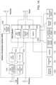
- FIG. 1 Bis a block diagram of an embodiment system of the present disclosure
- FIG. 3is a close-up photo of an inflated catheter balloon and tip in accordance with an aspect of the present disclosure.
- FIG. 4 Ais a flow diagram of a method in accordance with the present disclosure.
- FIG. 4 Bis a flow diagram of a method in accordance with the present disclosure.
- FIGS. 4 C- 4 Fshow the depth analysis performed along a single line in accordance with the present disclosure.
- FIG. 4 G and FIG. 4 Hshows the depth analysis in 3D with two ablation lesions and inter-lesion gap imaged with by fNADH, in accordance with the present disclosure.
- FIG. 5 A and FIG. 5 Bare a side-by-side plot of the emission wavelengths of healthy cardiac tissue ( FIG. 5 A ) and ablated cardiac tissue ( FIG. 5 B ).
- FIG. 6 A and FIG. 6 Bis a side-by side image comparison of a cardiac lesion illuminated under white light ( FIG. 6 A ) and the NADH fluorescence due to illumination under UV light ( FIG. 6 B ).
- FIG. 7 Ais a photo of an epicardial image showing a diameter measurement of a lesion viewed under UV illumination.
- FIG. 7 Bis a photo of a diameter measurement of the same lesion in FIG. 7 A , but as stained by triphenyltetrazoliun chlorate (TTC).
- TTCtriphenyltetrazoliun chlorate
- FIG. 7 Cis a plot of the correlation of a lesion size diameter measurement of the fluoresced lesions and TTC stained lesions.
- FIG. 8 Ais a plot of a correlation of a lesion depth to NADH fluorescence.
- FIG. 8 Bis a photo of a diameter measurement of two lesions revealed by staining with TTC.
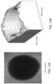
- FIG. 8 Cis a photo of a diameter measurement of fNAHD visualized lesions.
- FIG. 8 Dis an inverted signal of FIG. 8 C .
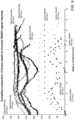
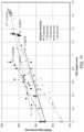
- FIG. 9is a plot of compiled data comparing a lesion depth to inverted NADH fluorescence intensity.
- FIG. 10is a 3D reconstruction of a depth of a lesion.
- FIG. 11is a plot of NADH fluorescence intensity versus a lesion depth varying ablation duration (time).
- FIG. 12 A and FIG. 12 Billustrate a lesion formed by cryo ablation and a 3D plot of the lesion, respectively.
- FIG. 12 C and FIG. 12 Dillustrate a lesion formed by radiofrequency ablation and a 3D plot of the lesion, respectively.
- FIG. 12 E and FIG. 12 Fillustrate three different lesions and a 3D plot showing a physical relation of the corresponding depths of the lesions, respectively. Interlesion gap is illustrated on the 3-D reconstruction image.
- FIG. 13 Ais an image of a lesion formed by cryprobe.
- the fluorescence of endogenous NADH (fNADH) in heart tissuecan be imaged in real-time to identify ablated and unablated areas. Gaps between ablated areas can be identified using the fNADH imaging and the gaps can then be ablated.
- the imagingcan be performed during the ablation procedure and does not require additional chemicals, such as contrast agents, tracers or dyes.
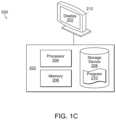
- Program 210can be a computer program or computer readable code containing instructions and/or data, and can be stored on storage device 208 .
- the instructionsmay comprise code from any computer-programming language, including, for example, C, C++, C#, Visual Basic, Java, Python, Perl, and JavaScript.
- processor 204may load some or all of the instructions and/or data of program 210 into memory 206 for execution.
- Program 210can be any computer program or process including, but not limited to web browser 166 , browser application 164 , address registration process 156 , application 142 , or any other computer application or process.
- the wavelength range on the illumination sourcemay be bounded by the anatomy of interest, specifically choosing a wavelength that causes maximum NADH fluorescence but not too much collagen fluorescence, which is activated by only slightly longer wavelengths.
- the laserhas a wavelength from 300 nm to 400 nm. In some embodiments, the laser has a wavelength from 330 nm to 370 nm. In some embodiments, the laser has a wavelength from 330 nm to 355 nm. In some embodiments, 355 nm may be used because it was near the peak of NADH excitation and just below collagen excitation. The output power of the laser may be high enough to produce a recoverable fluorescence data, yet not so high as to induce cellular damage.
- the operatormay deploy the balloon, which is installed around the distal portion of the catheter.
- NADHis excited by the UV light from the light source, such as a UV laser.
- NADH in the tissue specimenabsorbs the excitation wavelengths of light and emits longer wavelengths of light.
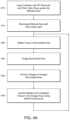
- the emission lightmay be collected and passed back to the camera, and a display of the imaged illuminated area may be produced on a display (step 430 ), which is used to identify the ablated and unablated tissue in the imaged area using NADH florescence (step 435 ).
- the processmay then be repeated by returning to the ablation step, if necessary to ablate additional tissue. It should be recognized that although FIG.
- FIG. 4 Aillustrates the steps being performed sequentially; many of the steps many be performed simultaneously or nearly simultaneously, or in a different order than shown in FIG. 4 A .
- the ablation, imaging and displaycan occur at the same time, and the identification of the ablated and unablated tissue can occur while ablating the tissue.
- the application softwareexecuting on the computer system by the processor or computer, can provide the user with an interface to the physician.
- Some of the main functionscan include: a laser control, a camera control, an image capture, an image conditioning (brightness and contrast adjustment, etc.), a lesion identification, a lesion depth analysis, a procedure event recording, and a file manipulation (creation, editing, deleting, etc.).
- this methoddrastically reduces the impact of patient-to-patient variations in absolute NADH fluorescence, as well as optical losses in the illumination and imaging systems and optical intensity variations resulting from specular and diffuse reflections, and other optical non-idealities.
- Step 465discloses the depth analysis performed along a single line across the lesion is completed. It is also possible that this can be done for just one single location in the lesions from information from a single location, a line or a region.
- FIGS. 4 C- 4 Fshow the depth analysis performed along a single line.
- FIG. 4 Cshows an image a canine heart that has been ablated six times. The square encases a single ablation lesion.
- FIG. 4 Dshows in the top right is an NADH fluorescence (fNADH) image obtained from the same area of a blood perfused canine heart.
- FIG. 4 Eis a 2d depth map performed along a single line and generated based on the digital image in FIG.
- FIG. 4 Dthat is, from the intensity of pixels forming the digital image.
- FIG. 4 Fis a hematoxylin and eosin stained canine heart tissue cut along the same line, which illustrates the actual depth of the lesion (the square illustrates the border of the lesion), with the deepest area corresponding to the darkest spot in FIG. 4 D and the lowest fNADH in FIG. 4 E .
- Step 470discloses repeating steps 460 to 470 along different lines parallel to the initial line, so the depth data of each line compiles into a 3D reconstruction model of the lesion site(s).
- the depth analysis process performed along a single line across the lesioncould be repeated as many times as needed along different lines parallel to the initial line, and the depth data of each line could be compiled into a 3D reconstruction model of the lesion site.
- FIG. 4 Gshows a digital image of two ablation lesions and inter-lesion gap imaged with by fNADH.
- FIG. 4 Hshows a 3D reconstruction from pixel intensity in the digital image of FIG. 4 G .
- Both the 2D data and the 3D datamay be used for further diagnosis or treatment, as described above.
- the intensity of fluorescence detected by the cameracan be measured and plotted with the lowest fluorescence (darkest) corresponding to the deepest lesions and the highest fluorescence (lightest) corresponding to the unablated or healthy tissue. Any levels of gray between the extremes of light and dark generally correspond to the degree of tissue lesion depth.
- the sensitivity of the camera sensordetermines the number of levels of gray between completely black and completely white. A few binary numbers are common in such applications including 256-level and 65,536-level, corresponding to 8-bit and 16-bit resolution, respectively. In the case of 8-bit sensitivity, 0 would be completely black and 255 completely white, with 254 levels of gray in between. Using this gray-scale image, a suitable depth map can be estimated. In some embodiments, 24 bit resolution may also be used.
- fNADH imagingcan reliably and reproducibly predict cardiac ablation lesion diameter and depth.
- the loss of fNADH intensitycorrelated with actual measured diameter and depth of multiple RF lesions with a correlation coefficient of greater 96% and 79%, respectively. It is possible that the loss of correlation at lesion depths greater than 2 mm occurred due to the inability of UV illumination to reliably penetrate cardiac tissue below this depth. With further lesion depth, no further fNADH could be detected and a reproducible plateau in fNADH signal intensity was thus observed at lesion depths of about 2 mm.
- the mean left atrial wall thickness at locations in the left atrium that are often targeted for ablationis 1.85 mm as measured by CT scans. Therefore, the observed nadir and plateau of fNADH signal intensity across an RF lesion serves as a plausible model for a clear, all-or-none determination of sufficient lesion depth.
- the methods, systems and devices disclosed hereincan be used for a variety of therapeutic procedures.
- Exemplary procedures in which the methods, systems and devices disclosed herein can be utilizedinclude, but not limited to, for diagnostic and therapeutic procedures in the heart, for treating arrhythmias, such as, for example, supraventricular arrhythmias and ventricular arrhythmias, for treating atrial fibrillation, and pulmonary vein mapping and ablation.
- the ablated tissuemay be cardiac muscle (epicardial or endocardial heart muscle), but the methods disclosed herein should have the same effect on skeletal muscle, liver, kidney, and other tissues with significant presence of NADH-rich mitochondria.
- the presently disclosed methodscan be used with two dimensional (2D) to three dimensional (3D) mapping protocols.
- a plurality of 2D imagescan be superimposed onto a 3D reconstruction image of the tissue or organs, including the heart.
- Many arrhythmia proceduresinclude the use of reconstructed three dimension images of the patient's specific anatomy during the procedure.
- imaging modalitiesincluding computed tomography (CT), magnetic resonance imaging (MRI), ultrasound, and electroanatomical mapping using systems such as NAVX and CARTO.
- CTcomputed tomography
- MRImagnetic resonance imaging
- ultrasoundelectroanatomical mapping
- the three dimensional anatomical images or surfacespresent patient specific anatomy to help target areas of tissue to treat.
- 2D image to 3D image mappingallows the system to superimpose, spatially register, and/or texture map single or multiple images of tissue (that may indicate presence or absence of lesions) with the specific anatomy of the patient in a three dimensional, rotatable, interactive virtual environment.
- the systems and methods of the present disclosureallow the registration and/or overlay of the images produced by the system onto the specific anatomy of the patient as seen using other imaging modalities such as an MRI image, computed tomography (CT) image, ultrasound image and three dimensional reconstructions thereof.
- the systems and methods of the present disclosuremay further include the registration and/or overlay of the images produced by the system onto the specific anatomy of the patient as seen using other electroanatomical mapping, anatomical reconstruction, and navigational systems such as NAVX and CARTO.
- the registration and overlaymay be performed during the procedure in real time. Texture mapping NADH images onto reconstructed endocardial surfaces permits visualization of the treatment site. For example, multiple NADH snapshots of lesions could create a full panoramic image of the entire pulmonary vein opening, or multiple pulmonary veins. Positioning sensors on the catheter tip could provide information that will allow the NADH images to be combined together to create a 3D reconstruction image.
- NADH Fluorescence Systemprovided that the epicardial surface was illuminated using an LED spotlight with a peak wavelength of 365 nm (PLS-0365-030-07-S, Mightex Systems). Emitted light was bandpass filtered at 460 nm+/ ⁇ 25 nm and imaged using a CCD camera (Andor Ixon DV860) fitted with a low magnification lens. The fluorescence of NADH (fNADH) was imaged to monitor the state of epicardial tissue.
- the RFA Systemprovided that RFA was performed with a standard clinical RF generator (EPT 1000 ablation system by Boston Scientific).
- the generatorwas electrically interfaced to the animal via a 4 mm cooled Blazer ablation catheter (Boston Scientific) in order to deliver lesions.
- a grounding padwas used at the time of ablation.
- the generatorwas set to temperature control mode.
- Cryoablationwere performed using custom-made metal probe dipped in liquid nitrogen or by using Freezor MAX Cardiac CryoAblation Catheter by Medtronic.
- FIG. 5 A and FIG. 5 Bfirst, baseline data were obtained for the NADH excitation and emission spectrum in healthy cardiac tissue.
- FIG. 5 A and FIG. 5 Bshow the tissue excitation—emission matrices. Due to the presence of NADH, healthy tissue emits strongly between 450 nm and 470 nm when excited in the range of 330 nm to 370 nm. The large peak associated with NADH is absent in ablated tissue.
- FIG. 6 A and FIG. 6 BAn example of a typical RFA lesion is shown in FIG. 6 A and FIG. 6 B .
- the image on the leftis captured using white light illumination while the f NADH image on the right is captured using UV excitation with a 460 nm filter.
- a systemcomprises a catheter having a distal and proximal end to image ablated pulmonary vein and left atrial heart tissue and unablated gaps, comprising an inflatable compliant or non-compliant balloon inflated with transparent fluid for displacing surrounding blood to allow visualization of NADH fluorescence at the distal end; an ultra-violet illumination device for illuminating the tissue at the distal end; and a micro fiberscope detecting the illuminated tissue at the distal end; a fluorescence camera at the proximal end for creating a 2D image, coupled to the fiberscope, that includes a filter that is configured to pass ultra-violet radiation from the illuminated tissue captured by the fiberscope; wherein the detected 2D image shows the lesion site having a dark appearance due to lack of fluorescence, gaps having a light appearance due to normal fluorescence, and any ischemic tissue having a brighter halo type appearance surrounded the lesion site; an ablation device for ablating heart tissue at the distal end based on the
- the moduleapplies a pixel gray scale ranging from completely black to completely white, where 0 is completely black and is the deepest point and 255 is completely white and is the shallowest point, providing 256 (0-255) levels of gray, to create a 2D map of the depth of the lesion site along the line.
- the 2D map of the depth of ablated tissueis an absolute measurement, with the fNADH signal intensity is normalized to a previously established fNADH/depth grey value scale.
- the present systems and methodsprovide for high quality and verifiable lesions, which can be at least one aspect to the success of the ablation procedure and avoidance of recurrence.
- Quality lesionsmay be of adequate depth and cause cell necrosis completely from the endocardial surface to the epicardial surface of the heart (i.e. transmural) while minimizing damage to the non-cardiac structures beyond.
- the presently disclosed systems and methodsprovide feedback as to the extent of cell injury caused by the ablation and actually verify the integrity of a lesion.
- the presently disclosed embodimentsovercome at least some of the problems of known technologies by addressing the lack of lesion-quality feedback by providing lesion visualization as well as depth-of-lesion information to the physician at the time of the procedure. This information should prove useful in forming and verifying proper lesions, reduce fluoroscopy time, and reduce the rate of arrhythmia occurrence, thereby improving outcomes and reducing costs.
- a method for determining a depth of a lesion sitethat includes illuminating a heart tissue having a lesion site; obtaining a mitochondrial nicotinamide adenine dinucleotide hydrogen (NADH) fluorescence intensity from the illuminated heart tissue along a first line across the lesion site; creating a 2-dimensional (2D) map of the depth of the lesion site along the first line based on the NADH fluorescence intensity; and determining a depth of the lesion site at a selected point along the first line from the 2D map, wherein a lower NADH fluorescence intensity corresponds to a greater depth in the lesion site and a higher NADH fluorescence intensity corresponds to an unablated tissue.
- NADHmitochondrial nicotinamide adenine dinucleotide hydrogen
- the step of detectingcomprises filtering the NADH fluorescence through a bandpass filter of between about 435 nm and 485 nm.
- the healthy tissuehas a lighter appearance and the lesion site has a darker appearance.
- the step of creatingmay comprise plotting the NADH fluorescence intensity along the line across the lesion site to create the 2D map of depth of the lesion site.
- the steps of obtaining, creating and determiningmay be repeated multiple times along a perpendicular line across a width of the lesion site, each of the 2D maps of the depth being parallel to the first line along the length of the lesion site; and integrating each of the respective 2D maps of the depth of the lesion site on a perpendicular line to reconstruct a 3D image of the depth of the lesion site.
- the step of determiningmay comprise applying a pixel gray scale ranging from completely black to completely white.
- the methodmay be used to analyze epicardial tissue, endocardial tissue, atrial tissue, and ventricular tissue.
Landscapes
- Health & Medical Sciences (AREA)
- Life Sciences & Earth Sciences (AREA)
- Surgery (AREA)
- Medical Informatics (AREA)
- Veterinary Medicine (AREA)
- Public Health (AREA)
- General Health & Medical Sciences (AREA)
- Animal Behavior & Ethology (AREA)
- Molecular Biology (AREA)
- Engineering & Computer Science (AREA)
- Biomedical Technology (AREA)
- Heart & Thoracic Surgery (AREA)
- Pathology (AREA)
- Physics & Mathematics (AREA)
- Biophysics (AREA)
- Nuclear Medicine, Radiotherapy & Molecular Imaging (AREA)
- Radiology & Medical Imaging (AREA)
- Cardiology (AREA)
- Otolaryngology (AREA)
- Physiology (AREA)
- Optics & Photonics (AREA)
- Oral & Maxillofacial Surgery (AREA)
- Investigating, Analyzing Materials By Fluorescence Or Luminescence (AREA)
- Endoscopes (AREA)
Abstract
Description
| Relative Changes of Auto- | ||
| Cellular State | NADH Presence | fluorescense intensity |
| Metabolically Active | Normal | Baseline |
| Metabolically Active but | Increased to | Increased |
| Impaired (Ischemia) | Hypoxia | |
| Metabolically Inactive | None | Full Attenuation |
| (Necrotic) | ||
Claims (19)
Priority Applications (1)
| Application Number | Priority Date | Filing Date | Title |
|---|---|---|---|
| US17/388,312US12343114B2 (en) | 2013-11-14 | 2021-07-29 | Systems and methods for determining lesion depth using fluorescence imaging |
Applications Claiming Priority (3)
| Application Number | Priority Date | Filing Date | Title |
|---|---|---|---|
| US201361904018P | 2013-11-14 | 2013-11-14 | |
| US14/541,991US11096584B2 (en) | 2013-11-14 | 2014-11-14 | Systems and methods for determining lesion depth using fluorescence imaging |
| US17/388,312US12343114B2 (en) | 2013-11-14 | 2021-07-29 | Systems and methods for determining lesion depth using fluorescence imaging |
Related Parent Applications (1)
| Application Number | Title | Priority Date | Filing Date |
|---|---|---|---|
| US14/541,991ContinuationUS11096584B2 (en) | 2013-11-14 | 2014-11-14 | Systems and methods for determining lesion depth using fluorescence imaging |
Publications (2)
| Publication Number | Publication Date |
|---|---|
| US20220142482A1 US20220142482A1 (en) | 2022-05-12 |
| US12343114B2true US12343114B2 (en) | 2025-07-01 |
Family
ID=53058268
Family Applications (2)
| Application Number | Title | Priority Date | Filing Date |
|---|---|---|---|
| US14/541,991Active2035-09-28US11096584B2 (en) | 2013-11-14 | 2014-11-14 | Systems and methods for determining lesion depth using fluorescence imaging |
| US17/388,312ActiveUS12343114B2 (en) | 2013-11-14 | 2021-07-29 | Systems and methods for determining lesion depth using fluorescence imaging |
Family Applications Before (1)
| Application Number | Title | Priority Date | Filing Date |
|---|---|---|---|
| US14/541,991Active2035-09-28US11096584B2 (en) | 2013-11-14 | 2014-11-14 | Systems and methods for determining lesion depth using fluorescence imaging |
Country Status (3)
| Country | Link |
|---|---|
| US (2) | US11096584B2 (en) |
| JP (2) | JP6737705B2 (en) |
| WO (1) | WO2015073871A2 (en) |
Families Citing this family (30)
| Publication number | Priority date | Publication date | Assignee | Title |
|---|---|---|---|---|
| US10586341B2 (en) | 2011-03-04 | 2020-03-10 | General Electric Company | Method and device for measuring features on or near an object |
| US10157495B2 (en)* | 2011-03-04 | 2018-12-18 | General Electric Company | Method and device for displaying a two-dimensional image of a viewed object simultaneously with an image depicting the three-dimensional geometry of the viewed object |
| US9875574B2 (en)* | 2013-12-17 | 2018-01-23 | General Electric Company | Method and device for automatically identifying the deepest point on the surface of an anomaly |
| AU2012312066C1 (en) | 2011-09-22 | 2016-06-16 | 460Medical, Inc. | Systems and methods for visualizing ablated tissue |
| US9014789B2 (en) | 2011-09-22 | 2015-04-21 | The George Washington University | Systems and methods for visualizing ablated tissue |
| JP6737705B2 (en) | 2013-11-14 | 2020-08-12 | ザ・ジョージ・ワシントン・ユニバーシティThe George Washingtonuniversity | Method of operating system for determining depth of injury site and system for generating images of heart tissue |
| JP2017500550A (en) | 2013-11-20 | 2017-01-05 | ザ・ジョージ・ワシントン・ユニバーシティThe George Washingtonuniversity | System and method for hyperspectral analysis of cardiac tissue |
| US9818039B2 (en)* | 2013-12-17 | 2017-11-14 | General Electric Company | Method and device for automatically identifying a point of interest in a depth measurement on a viewed object |
| EP3215001A4 (en) | 2014-11-03 | 2018-04-04 | Luxcath, LLC | Systems and methods for assessment of contact quality |
| KR102499045B1 (en) | 2014-11-03 | 2023-02-10 | 더 조지 워싱턴 유니버시티 | Systems and methods for lesion assessment |
| JP6401098B2 (en)* | 2015-03-30 | 2018-10-03 | 富士フイルム株式会社 | Endoscopic diagnosis apparatus and operation method of endoscopic diagnosis apparatus |
| CN107635503B (en) | 2015-05-12 | 2021-09-07 | 纳维斯国际有限公司 | Damage estimation by dielectric property analysis |
| US10779904B2 (en) | 2015-07-19 | 2020-09-22 | 460Medical, Inc. | Systems and methods for lesion formation and assessment |
| CN109310333A (en)* | 2016-06-11 | 2019-02-05 | 波士顿科学医学有限公司 | Systems and methods for monitoring tissue ablation using tissue autofluorescence |
| WO2018044919A1 (en)* | 2016-09-01 | 2018-03-08 | The George Washington University | Enzyme-dependent fluorescence recovery of nadh after photobleaching to assess dehydrogenase activity of living tissues |
| WO2018092071A1 (en)* | 2016-11-16 | 2018-05-24 | Navix International Limited | Estimators for ablation effectiveness |
| US10332252B2 (en) | 2016-12-29 | 2019-06-25 | General Electric Company | Slope constrained cubic interpolation |
| US10806503B2 (en) | 2017-02-06 | 2020-10-20 | General Electric Company | Methods and systems for electrophysiology ablation gap analysis |
| US10765371B2 (en)* | 2017-03-31 | 2020-09-08 | Biosense Webster (Israel) Ltd. | Method to project a two dimensional image/photo onto a 3D reconstruction, such as an epicardial view of heart |
| EP3499258A1 (en) | 2017-12-13 | 2019-06-19 | BIOTRONIK SE & Co. KG | Device and method for determining a local property of a biological tissue by means of an nmr sensor |
| JP7165936B2 (en) | 2018-04-13 | 2022-11-07 | 国立研究開発法人理化学研究所 | TRAINING DEVICE, IMAGE PROCESSING METHOD, PROGRAM, AND INFORMATION RECORDING MEDIUM |
| WO2020053933A1 (en)* | 2018-09-10 | 2020-03-19 | オリンパス株式会社 | Thermal insult observation device and thermal insult observation method |
| JP7212756B2 (en)* | 2019-02-28 | 2023-01-25 | オリンパス株式会社 | Medical system, energy control method, and processor |
| CN111166470B (en)* | 2019-10-15 | 2021-06-18 | 东北大学 | Depth-distinguishable target detection and ablation system |
| CN114727839A (en)* | 2019-11-18 | 2022-07-08 | 瑟卡科学有限公司 | Device port for epicardial ablation with inflatable balloon |
| EP4087511A4 (en) | 2020-01-08 | 2024-02-14 | 460Medical, Inc. | Systems and methods for optical interrogation of ablation lesions |
| JP7434591B2 (en) | 2020-09-29 | 2024-02-20 | オリンパス株式会社 | Support devices, endoscope systems, support methods and programs |
| CN113808137A (en)* | 2021-11-19 | 2021-12-17 | 武汉楚精灵医疗科技有限公司 | Method, device, equipment and storage medium for screening image map of upper gastrointestinal endoscope |
| CN120641021A (en)* | 2023-02-09 | 2025-09-12 | 奥林巴斯医疗株式会社 | Medical device, medical system, learning device, operating method and program of medical device |
| CN119169179B (en)* | 2023-12-12 | 2025-09-05 | 常州联影智融医疗科技有限公司 | Three-dimensional reconstruction method, device, image processing equipment and endoscope system |
Citations (388)
| Publication number | Priority date | Publication date | Assignee | Title |
|---|---|---|---|---|
| US3387305A (en) | 1966-02-09 | 1968-06-11 | Rocky Mountain Sports | Knee protector |
| US3831467A (en) | 1973-03-16 | 1974-08-27 | R Moore | Knee brace |
| US4024873A (en) | 1976-05-24 | 1977-05-24 | Becton, Dickinson And Company | Balloon catheter assembly |
| JPS60182928A (en) | 1984-03-01 | 1985-09-18 | オリンパス光学工業株式会社 | Endoscope having solid image pick-up element mounted therein |
| US4619247A (en) | 1983-03-31 | 1986-10-28 | Sumitomo Electric Industries, Ltd. | Catheter |
| JPS63262613A (en) | 1987-04-20 | 1988-10-28 | Olympus Optical Co Ltd | Stereoscopic vision endoscope device |
| US5074306A (en) | 1990-02-22 | 1991-12-24 | The General Hospital Corporation | Measurement of burn depth in skin |
| US5187572A (en) | 1990-10-31 | 1993-02-16 | Olympus Optical Co., Ltd. | Endoscope system with a plurality of synchronized light source apparatuses |
| US5350375A (en) | 1993-03-15 | 1994-09-27 | Yale University | Methods for laser induced fluorescence intensity feedback control during laser angioplasty |
| US5419323A (en) | 1988-12-21 | 1995-05-30 | Massachusetts Institute Of Technology | Method for laser induced fluorescence of tissue |
| US5421337A (en) | 1989-04-14 | 1995-06-06 | Massachusetts Institute Of Technology | Spectral diagnosis of diseased tissue |
| US5507287A (en) | 1991-05-08 | 1996-04-16 | Xillix Technologies Corporation | Endoscopic imaging system for diseased tissue |
| US5540681A (en) | 1992-04-10 | 1996-07-30 | Medtronic Cardiorhythm | Method and system for radiofrequency ablation of tissue |
| US5584799A (en) | 1989-09-11 | 1996-12-17 | Gray; James C. | Splint/therapeutic device |
| US5590660A (en) | 1994-03-28 | 1997-01-07 | Xillix Technologies Corp. | Apparatus and method for imaging diseased tissue using integrated autofluorescence |
| US5657760A (en) | 1994-05-03 | 1997-08-19 | Board Of Regents, The University Of Texas System | Apparatus and method for noninvasive doppler ultrasound-guided real-time control of tissue damage in thermal therapy |
| WO1997037622A1 (en) | 1996-04-08 | 1997-10-16 | The University Of Southern California | Method and apparatus for using laser-induced fluorescence during photoretractive keratectomy |
| US5713364A (en) | 1995-08-01 | 1998-02-03 | Medispectra, Inc. | Spectral volume microprobe analysis of materials |
| US5749830A (en) | 1993-12-03 | 1998-05-12 | Olympus Optical Co., Ltd. | Fluorescent endoscope apparatus |
| JPH10150177A (en) | 1996-11-18 | 1998-06-02 | Nec Corp | Solid-state imaging device |
| US5833688A (en) | 1997-02-24 | 1998-11-10 | Boston Scientific Corporation | Sensing temperature with plurality of catheter sensors |
| US5865754A (en)* | 1995-08-24 | 1999-02-02 | Purdue Research Foundation Office Of Technology Transfer | Fluorescence imaging system and method |
| US5885258A (en) | 1996-02-23 | 1999-03-23 | Memory Medical Systems, Inc. | Medical instrument with slotted memory metal tube |
| WO1999013934A1 (en) | 1997-09-12 | 1999-03-25 | Nippon Zeon Co., Ltd. | Balloon catheter |
| US5904651A (en) | 1996-10-28 | 1999-05-18 | Ep Technologies, Inc. | Systems and methods for visualizing tissue during diagnostic or therapeutic procedures |
| US5954665A (en) | 1995-06-07 | 1999-09-21 | Biosense, Inc. | Cardiac ablation catheter using correlation measure |
| US6112123A (en) | 1998-07-28 | 2000-08-29 | Endonetics, Inc. | Device and method for ablation of tissue |
| US6124597A (en) | 1997-07-07 | 2000-09-26 | Cedars-Sinai Medical Center | Method and devices for laser induced fluorescence attenuation spectroscopy |
| WO2001001854A2 (en) | 1999-07-02 | 2001-01-11 | Hypermed Imaging, Inc. | Integrated imaging apparatus |
| US6174291B1 (en) | 1998-03-09 | 2001-01-16 | Spectrascience, Inc. | Optical biopsy system and methods for tissue diagnosis |
| US6178346B1 (en) | 1998-10-23 | 2001-01-23 | David C. Amundson | Infrared endoscopic imaging in a liquid with suspended particles: method and apparatus |
| US6197021B1 (en) | 1994-08-08 | 2001-03-06 | Ep Technologies, Inc. | Systems and methods for controlling tissue ablation using multiple temperature sensing elements |
| US6208886B1 (en)* | 1997-04-04 | 2001-03-27 | The Research Foundation Of City College Of New York | Non-linear optical tomography of turbid media |
| CN1289239A (en) | 1998-01-26 | 2001-03-28 | 麻省理工学院 | Fluorescence imaging endoscope |
| US6219566B1 (en) | 1999-07-13 | 2001-04-17 | Photonics Research Ontario | Method of measuring concentration of luminescent materials in turbid media |
| US6217573B1 (en) | 1998-12-03 | 2001-04-17 | Cordis Webster | System and method for measuring surface temperature of tissue during ablation |
| US6251107B1 (en) | 1998-06-25 | 2001-06-26 | Cardima, Inc. | Ep catheter |
| US6289236B1 (en) | 1997-10-10 | 2001-09-11 | The General Hospital Corporation | Methods and apparatus for distinguishing inflamed and tumorous bladder tissue |
| WO2001072214A1 (en) | 2000-03-28 | 2001-10-04 | Foundation For Research And Technology-Hellas | Method and system for characterization and mapping of tissue lesions |
| US6309352B1 (en) | 1996-01-31 | 2001-10-30 | Board Of Regents, The University Of Texas System | Real time optoacoustic monitoring of changes in tissue properties |
| US6343228B1 (en) | 1999-10-19 | 2002-01-29 | The Hong Kong University Of Science And Technology | Method and apparatus for fluorescence imaging of tissue |
| US20020042556A1 (en) | 2000-10-05 | 2002-04-11 | Asahi Kogaku Kogyo Kabushiki Kaisha | Video endoscope system |
| US6423055B1 (en) | 1999-07-14 | 2002-07-23 | Cardiofocus, Inc. | Phototherapeutic wave guide apparatus |
| US6423057B1 (en) | 1999-01-25 | 2002-07-23 | The Arizona Board Of Regents On Behalf Of The University Of Arizona | Method and apparatus for monitoring and controlling tissue temperature and lesion formation in radio-frequency ablation procedures |
| US20020123666A1 (en) | 2001-03-05 | 2002-09-05 | Olympus Optical Co., Ltd. | Light source device for endoscopes |
| US6450971B1 (en) | 2000-10-05 | 2002-09-17 | Scimed Life Systems, Inc. | Temperature measuring balloon |
| US20020143326A1 (en) | 2000-02-11 | 2002-10-03 | Lotek, Inc. | Surgical devices and methods for use in tissue ablation procedures |
| US6485413B1 (en) | 1991-04-29 | 2002-11-26 | The General Hospital Corporation | Methods and apparatus for forward-directed optical scanning instruments |
| US6516217B1 (en) | 1999-07-09 | 2003-02-04 | Fuji Photo Film Co., Ltd. | Fluorescence diagnosis system |
| US20030028188A1 (en) | 1997-09-30 | 2003-02-06 | Scimed Life Systems, Inc. | Deflectable interstitial ablation device |
| US6542767B1 (en) | 1999-11-09 | 2003-04-01 | Biotex, Inc. | Method and system for controlling heat delivery to a target |
| US6572609B1 (en) | 1999-07-14 | 2003-06-03 | Cardiofocus, Inc. | Phototherapeutic waveguide apparatus |
| US6584360B2 (en) | 2000-04-27 | 2003-06-24 | Medtronic Inc. | System and method for assessing transmurality of ablation lesions |
| US20030120142A1 (en) | 2001-09-28 | 2003-06-26 | Marc Dubuc | Method for identification and visualization of atrial tissue and therapeutical use thereof |
| US20030120144A1 (en) | 2001-11-16 | 2003-06-26 | Grabek James R. | Intrapericardial temperature measurement device and method |
| US20030125719A1 (en) | 2001-12-31 | 2003-07-03 | Furnish Simon M. | Multi-fiber catheter probe arrangement for tissue analysis or treatment |
| US20030208252A1 (en) | 2001-05-14 | 2003-11-06 | O' Boyle Gary S. | Mri ablation catheter |
| WO2003092520A1 (en) | 2002-05-06 | 2003-11-13 | Sherwood Services Ag | Blood detector for controlling anesu and method therefor |
| US6648883B2 (en) | 2001-04-26 | 2003-11-18 | Medtronic, Inc. | Ablation system and method of use |
| US6663627B2 (en) | 2001-04-26 | 2003-12-16 | Medtronic, Inc. | Ablation system and method of use |
| US6716196B2 (en) | 1993-07-30 | 2004-04-06 | The Regents Of The University Of California | Catheter system for delivery of Therapeutic compounds to cardiac tissue |
| WO2004028353A2 (en) | 2002-09-30 | 2004-04-08 | Vanderbilt University | Optical apparatus for guided liver tumor treatment and methods |
| US20040092806A1 (en) | 2001-12-11 | 2004-05-13 | Sagon Stephen W | Microelectrode catheter for mapping and ablation |
| US20040097788A1 (en) | 2002-05-30 | 2004-05-20 | Mourlas Nicholas J. | Apparatus and methods for coronary sinus access |
| US6743225B2 (en) | 2001-03-27 | 2004-06-01 | Uab Research Foundation | Electrophysiologic measure of endpoints for ablation lesions created in fibrillating substrates |
| US6746401B2 (en) | 2002-05-06 | 2004-06-08 | Scimed Life Systems, Inc. | Tissue ablation visualization |
| US6761716B2 (en) | 2001-09-18 | 2004-07-13 | Cardiac Pacemakers, Inc. | System and method for assessing electrode-tissue contact and lesion quality during RF ablation by measurement of conduction time |
| US20040187875A1 (en) | 2001-05-01 | 2004-09-30 | He Sheng Ding | Method and apparatus for altering conduction properties along pathways in the heart and in vessels in conductive communication with the heart. |
| US20040215310A1 (en) | 2002-01-17 | 2004-10-28 | Omar Amirana | Stent and delivery method for applying RF energy to a pulmonary vein and the atrial wall around its ostium to eliminate atrial fibrillation while preventing stenosis of the pulmonary vein thereafter |
| US6825928B2 (en) | 2001-12-19 | 2004-11-30 | Wisconsin Alumni Research Foundation | Depth-resolved fluorescence instrument |
| US20040267326A1 (en) | 2002-01-25 | 2004-12-30 | Ocel Jon M | Cardiac mapping instrument with shapeable electrode |
| US20050014995A1 (en) | 2001-11-09 | 2005-01-20 | David Amundson | Direct, real-time imaging guidance of cardiac catheterization |
| US20050043637A1 (en) | 2003-08-22 | 2005-02-24 | Infraredx, Inc. | Method and system for spectral examination of vascular walls through blood during cardiac motion |
| US20050070987A1 (en) | 2003-09-25 | 2005-03-31 | Advanced Neuromodulation Systems, Inc. | System and method for implantable stimulation lead employing optical fibers |
| US20050075629A1 (en) | 2002-02-19 | 2005-04-07 | Afx, Inc. | Apparatus and method for assessing tissue ablation transmurality |
| US20050119523A1 (en) | 2003-09-03 | 2005-06-02 | Guided Delivery Systems, Inc. | Cardiac visualization devices and methods |
| US20050119548A1 (en) | 2002-07-05 | 2005-06-02 | Vanderbilt University | Method and apparatus for optical spectroscopic detection of cell and tissue death |
| US6937885B1 (en) | 1997-10-30 | 2005-08-30 | Hypermed, Inc. | Multispectral/hyperspectral medical instrument |
| US6936047B2 (en) | 2000-05-12 | 2005-08-30 | Agility Capital Llc | Multi-channel RF energy delivery with coagulum reduction |
| US20050197623A1 (en) | 2004-02-17 | 2005-09-08 | Leeflang Stephen A. | Variable steerable catheters and methods for using them |
| US20050197530A1 (en) | 2003-09-25 | 2005-09-08 | Wallace Daniel T. | Balloon visualization for traversing a tissue wall |
| US20050215899A1 (en) | 2004-01-15 | 2005-09-29 | Trahey Gregg E | Methods, systems, and computer program products for acoustic radiation force impulse (ARFI) imaging of ablated tissue |
| US20050228452A1 (en) | 2004-02-11 | 2005-10-13 | Mourlas Nicholas J | Steerable catheters and methods for using them |
| US20050251125A1 (en) | 1998-09-21 | 2005-11-10 | Epicor Medical, Inc. | Apparatus and method for ablating tissue |
| US6975899B2 (en) | 1998-09-11 | 2005-12-13 | Spectrx, Inc. | Multi-modal optical tissue diagnostic system |
| US6974454B2 (en) | 2000-04-27 | 2005-12-13 | Atricure, Inc. | Transmural ablation device with thermocouple for measuring tissue temperature |
| US6975898B2 (en) | 2000-06-19 | 2005-12-13 | University Of Washington | Medical imaging, diagnosis, and therapy using a scanning single optical fiber system |
| US20050283195A1 (en) | 2004-06-18 | 2005-12-22 | Pastore Joseph M | Methods and apparatuses for localizing myocardial infarction during catheterization |
| US20060009756A1 (en) | 2004-05-14 | 2006-01-12 | Francischelli David E | Method and devices for treating atrial fibrillation by mass ablation |
| US20060013454A1 (en)* | 2003-04-18 | 2006-01-19 | Medispectra, Inc. | Systems for identifying, displaying, marking, and treating suspect regions of tissue |
| US6989010B2 (en) | 2001-04-26 | 2006-01-24 | Medtronic, Inc. | Ablation system and method of use |
| US7001383B2 (en) | 2002-10-21 | 2006-02-21 | Biosense, Inc. | Real-time monitoring and mapping of ablation lesion formation in the heart |
| WO2006028824A1 (en) | 2004-09-02 | 2006-03-16 | Medtronic, Inc. | Ablation-therapy of cardiac arrhythmias |
| CN1764419A (en) | 2003-02-20 | 2006-04-26 | 普罗里森姆股份有限公司 | Cardiac ablation devices |
| US20060089636A1 (en) | 2004-10-27 | 2006-04-27 | Christopherson Mark A | Ultrasound visualization for transurethral needle ablation |
| US7047068B2 (en) | 2000-12-11 | 2006-05-16 | C.R. Bard, Inc. | Microelectrode catheter for mapping and ablation |
| US20060122583A1 (en) | 2002-06-25 | 2006-06-08 | Glucon Inc | Method and apparatus for performing myocardial revascularization |
| US20060122587A1 (en) | 2004-11-17 | 2006-06-08 | Shiva Sharareh | Apparatus for real time evaluation of tissue ablation |
| US20060118742A1 (en)* | 2004-12-06 | 2006-06-08 | Richard Levenson | Systems and methods for in-vivo optical imaging and measurement |
| JP2006158546A (en) | 2004-12-03 | 2006-06-22 | Topcon Corp | Spectral fundus image data measurement device |
| US20060184048A1 (en) | 2005-02-02 | 2006-08-17 | Vahid Saadat | Tissue visualization and manipulation system |
| US20060229515A1 (en) | 2004-11-17 | 2006-10-12 | The Regents Of The University Of California | Fiber optic evaluation of tissue modification |
| US20060229594A1 (en)* | 2000-01-19 | 2006-10-12 | Medtronic, Inc. | Method for guiding a medical device |
| US7130672B2 (en) | 2000-09-25 | 2006-10-31 | Critisense Ltd. | Apparatus and method for monitoring tissue vitality parameters |
| DE102005021205A1 (en) | 2005-05-07 | 2006-11-16 | Mfd Diagnostics Gmbh | Detection of vitality of living cells in cell culture or tissue by nicotinamide adenine dinucleotide hydrogenase fluorescence spectroscopy, comprises irradiating the cells by short periodically produced light pulses in the near ultraviolet |
| US20060278246A1 (en) | 2003-05-21 | 2006-12-14 | Michael Eng | Electrophysiology catheter |
| US20070016079A1 (en) | 2005-04-04 | 2007-01-18 | Freeman Jenny E | Hyperspectral imaging in diabetes and peripheral vascular disease |
| US20070016130A1 (en) | 2005-05-06 | 2007-01-18 | Leeflang Stephen A | Complex Shaped Steerable Catheters and Methods for Making and Using Them |
| US20070038126A1 (en) | 2005-06-23 | 2007-02-15 | Pyle Jason L | System and method for monitoring of end organ oxygenation by measurement of in vivo cellular energy status |
| US20070049827A1 (en) | 2005-08-16 | 2007-03-01 | General Electric Company | Clinical feedback of ablation efficacy during ablation procedure |
| US7192427B2 (en) | 2002-02-19 | 2007-03-20 | Afx, Inc. | Apparatus and method for assessing transmurality of a tissue ablation |
| WO2007041542A2 (en) | 2005-09-30 | 2007-04-12 | Cornova, Inc. | Systems and methods for analysis and treatment of a body lumen |
| US20070083217A1 (en) | 2002-05-30 | 2007-04-12 | Eversull Christian S | Apparatus and Methods for Placing Leads Using Direct Visualization |
| US7232437B2 (en) | 2003-10-30 | 2007-06-19 | Medical Cv, Inc. | Assessment of lesion transmurality |
| US20070167828A1 (en) | 2005-02-02 | 2007-07-19 | Vahid Saadat | Tissue imaging system variations |
| US7250048B2 (en) | 2001-04-26 | 2007-07-31 | Medtronic, Inc. | Ablation system and method of use |
| US20070179487A1 (en) | 2006-02-01 | 2007-08-02 | The General Hospital Corporation | Apparatus for applying a plurality of electro-magnetic radiations to a sample |
| US7252664B2 (en) | 2000-05-12 | 2007-08-07 | Cardima, Inc. | System and method for multi-channel RF energy delivery with coagulum reduction |
| US20070185479A1 (en) | 2006-02-06 | 2007-08-09 | Liming Lau | Methods and devices for performing ablation and assessing efficacy thereof |
| US7255695B2 (en) | 2001-04-27 | 2007-08-14 | C.R. Bard, Inc. | Systems and methods for three-dimensional mapping of electrical activity |
| US20070225697A1 (en) | 2006-03-23 | 2007-09-27 | Ketan Shroff | Apparatus and methods for cardiac ablation |
| WO2007109554A2 (en) | 2006-03-17 | 2007-09-27 | Voyage Medical, Inc. | Tissue visualization and manipulation systems |
| US7289205B2 (en) | 2003-09-19 | 2007-10-30 | The General Hospital Corporation | Fluorescence polarization imaging devices and methods |
| US20070270789A1 (en) | 2003-10-20 | 2007-11-22 | The Johns Hopkins University | Catheter and Method for Ablation of Atrial Tissue |
| US20070270717A1 (en) | 2005-09-30 | 2007-11-22 | Cornova, Inc. | Multi-faceted optical reflector |
| US20070270792A1 (en) | 2006-05-08 | 2007-11-22 | Willard Hennemann | Interferometric characterization of ablated tissue |
| US20070276259A1 (en) | 2006-05-29 | 2007-11-29 | Olympus Corporation | Lesion extracting device and lesion extracting method |
| US7306593B2 (en) | 2002-10-21 | 2007-12-11 | Biosense, Inc. | Prediction and assessment of ablation of cardiac tissue |
| US20070287886A1 (en) | 2005-02-02 | 2007-12-13 | Voyage Medical Inc. | Tissue visualization and manipulation systems |
| US20070293724A1 (en) | 2005-02-02 | 2007-12-20 | Voyage Medical, Inc. | Visualization apparatus for transseptal access |
| US20080009747A1 (en) | 2005-02-02 | 2008-01-10 | Voyage Medical, Inc. | Transmural subsurface interrogation and ablation |
| US20080015569A1 (en) | 2005-02-02 | 2008-01-17 | Voyage Medical, Inc. | Methods and apparatus for treatment of atrial fibrillation |
| US20080021275A1 (en) | 2006-01-19 | 2008-01-24 | The General Hospital Corporation | Methods and systems for optical imaging or epithelial luminal organs by beam scanning thereof |
| US20080033241A1 (en) | 2006-08-01 | 2008-02-07 | Ruey-Feng Peh | Left atrial appendage closure |
| US7338485B2 (en) | 2003-10-30 | 2008-03-04 | Medical Cv, Inc. | Cardiac lesions with continuity testing |
| US20080058785A1 (en) | 2006-04-12 | 2008-03-06 | Searete Llc, A Limited Liability Corporation Of The State Of Delaware | Autofluorescent imaging and target ablation |
| WO2008028149A2 (en) | 2006-09-01 | 2008-03-06 | Voyage Medical, Inc. | Electrophysiology mapping and visualization system |
| US20080058786A1 (en) | 2006-04-12 | 2008-03-06 | Searete Llc, A Limited Liability Corporation Of The State Of Delaware | Autofluorescent imaging and target ablation |
| US20080058650A1 (en) | 2006-09-01 | 2008-03-06 | Voyage Medical, Inc. | Coronary sinus cannulation |
| US20080097476A1 (en) | 2006-09-01 | 2008-04-24 | Voyage Medical, Inc. | Precision control systems for tissue visualization and manipulation assemblies |
| US20080101677A1 (en) | 2006-10-27 | 2008-05-01 | Siemens Aktiengesellschaft | Apparatus for generating sectional images of tissue |
| US7367944B2 (en) | 2004-12-13 | 2008-05-06 | Tel Hashomer Medical Research Infrastructure And Services Ltd. | Method and system for monitoring ablation of tissues |
| WO2008054423A1 (en) | 2006-10-31 | 2008-05-08 | University Of Washington | Magnetically controllable elongate device, systems and methods |
| US20080119694A1 (en) | 2006-11-17 | 2008-05-22 | Lee James K | Catheter with omni-Directional optical tip having isolated optical paths |
| US20080125634A1 (en) | 2006-06-14 | 2008-05-29 | Cornova, Inc. | Method and apparatus for identifying and treating myocardial infarction |
| US20080154257A1 (en) | 2006-12-22 | 2008-06-26 | Shiva Sharareh | Real-time optoacoustic monitoring with electophysiologic catheters |
| US20080172049A1 (en) | 2005-08-25 | 2008-07-17 | Koninklijke Philips Electronics, N.V. | System and Method For Electrophysiology Regaining Support to Continue Line and Ring Ablations |
| US20080183036A1 (en) | 2006-12-18 | 2008-07-31 | Voyage Medical, Inc. | Systems and methods for unobstructed visualization and ablation |
| US7417740B2 (en) | 2004-11-12 | 2008-08-26 | Medeikon Corporation | Single trace multi-channel low coherence interferometric sensor |
| US20080212867A1 (en) | 2007-03-02 | 2008-09-04 | Provenzano Paolo P | Use of Endogenous Fluorescence to Identify Invading Metastatic Breast Tumor Cells |
| US20080214889A1 (en) | 2006-10-23 | 2008-09-04 | Voyage Medical, Inc. | Methods and apparatus for preventing tissue migration |
| US20080221448A1 (en) | 2007-03-07 | 2008-09-11 | Khuri-Yakub Butrus T | Image-guided delivery of therapeutic tools duing minimally invasive surgeries and interventions |
| US20080228079A1 (en) | 2007-03-16 | 2008-09-18 | Donaldson Brenda L | Clinical utilization of contrast agents to define specific areas within the myocardial wall to provide guidance and localization for ablation, cyroablation, or other techniques in patients with post myocardial infarction |
| WO2008114748A1 (en) | 2007-03-20 | 2008-09-25 | Olympus Corporation | Fluorescence monitoring apparatus |
| US20080243214A1 (en) | 2007-03-26 | 2008-10-02 | Boston Scientific Scimed, Inc. | High resolution electrophysiology catheter |
| US20080275300A1 (en) | 2007-04-27 | 2008-11-06 | Voyage Medical, Inc. | Complex shape steerable tissue visualization and manipulation catheter |
| US20080281293A1 (en) | 2007-05-08 | 2008-11-13 | Voyage Medical, Inc. | Complex shape steerable tissue visualization and manipulation catheter |
| US20080300589A1 (en) | 2005-12-06 | 2008-12-04 | Saurav Paul | Assessment of Electrode Coupling for Tissue Ablation |
| WO2008154578A1 (en) | 2007-06-11 | 2008-12-18 | Board Of Regents, The University Of Texas System | Characterization of a near-infrared laparoscopic hyperspectral imaging system |
| US20090012367A1 (en) | 2003-12-17 | 2009-01-08 | Boston Scientific Scimed, Inc. | Medical device with oled illumination light source |
| US20090030412A1 (en) | 2007-05-11 | 2009-01-29 | Willis N Parker | Visual electrode ablation systems |
| US20090030276A1 (en) | 2007-07-27 | 2009-01-29 | Voyage Medical, Inc. | Tissue visualization catheter with imaging systems integration |
| US20090062790A1 (en) | 2007-08-31 | 2009-03-05 | Voyage Medical, Inc. | Direct visualization bipolar ablation systems |
| US20090076373A1 (en) | 2007-09-13 | 2009-03-19 | Siemens Aktiengesellschaft | Medical imaging facility, in particular for producing image recordings in the context of a treatment of cardiac arrhythmias, and associated method |
| US20090076375A1 (en) | 2007-09-13 | 2009-03-19 | Siemens Aktiengesellschaft | Myocardial tissue ablation device for treatment of cardiac arrhythmias by ablation of myocardial tissue in a patient as well as associated catheter and associated method |
| US20090082660A1 (en) | 2007-09-20 | 2009-03-26 | Norbert Rahn | Clinical workflow for treatment of atrial fibrulation by ablation using 3d visualization of pulmonary vein antrum in 2d fluoroscopic images |
| US20090082623A1 (en) | 2006-06-07 | 2009-03-26 | Rothe Chris A | Visualization and treatment via percutaneous methods and devices |
| NL2002010A1 (en) | 2007-09-28 | 2009-03-31 | Gen Electric | Imaging and navigation system. |
| US7527625B2 (en) | 2004-08-04 | 2009-05-05 | Olympus Corporation | Transparent electrode for the radiofrequency ablation of tissue |
| US20090125022A1 (en) | 2007-11-12 | 2009-05-14 | Voyage Medical, Inc. | Tissue visualization and ablation systems |
| US20090131931A1 (en) | 2007-11-16 | 2009-05-21 | Lee James K | Catheter with omni-directional optical tip having isolated optical paths |
| US20090143640A1 (en) | 2007-11-26 | 2009-06-04 | Voyage Medical, Inc. | Combination imaging and treatment assemblies |
| US20090203962A1 (en) | 2008-02-07 | 2009-08-13 | Voyage Medical, Inc. | Stent delivery under direct visualization |
| US20090204069A1 (en) | 2005-10-14 | 2009-08-13 | Eran Hirszowicz | Balloon Catheter |
| US7587236B2 (en) | 2004-01-08 | 2009-09-08 | Lawrence Livermore National Security, Llc | Optical spectroscopy for the detection of ischemic tissue injury |
| US7591816B2 (en) | 2006-12-28 | 2009-09-22 | St. Jude Medical, Atrial Fibrillation Division, Inc. | Irrigated ablation catheter having a pressure sensor to detect tissue contact |
| US7596404B2 (en) | 2001-06-28 | 2009-09-29 | Chemimage Corporation | Method of chemical imaging to determine tissue margins during surgery |
| US20090275799A1 (en) | 2006-12-21 | 2009-11-05 | Voyage Medical, Inc. | Axial visualization systems |
| US20090281541A1 (en) | 2008-05-09 | 2009-11-12 | Estech, Inc. | Conduction block systems and methods |
| US20090299354A1 (en) | 1999-07-14 | 2009-12-03 | Cardiofocus, Inc. | Cardiac ablation catheters for forming overlapping lesions |
| US20090306643A1 (en) | 2008-02-25 | 2009-12-10 | Carlo Pappone | Method and apparatus for delivery and detection of transmural cardiac ablation lesions |
| US20090326385A1 (en) | 2006-12-06 | 2009-12-31 | Koninklijke Philips Electronics N.V. | Obtaining optical tissue properties |
| US20100022832A1 (en) | 2008-07-28 | 2010-01-28 | Olympus Medical Systems Corp. | Endoscope insertion aid and endoscope apparatus |
| US7662152B2 (en) | 2006-06-13 | 2010-02-16 | Biosense Webster, Inc. | Catheter with multi port tip for optical lesion evaluation |
| US20100041986A1 (en) | 2008-07-23 | 2010-02-18 | Tho Hoang Nguyen | Ablation and monitoring system including a fiber optic imaging catheter and an optical coherence tomography system |
| US20100056966A1 (en) | 2006-01-13 | 2010-03-04 | Landy Toth | Device, system and method for compression treatment of a body part |
| US7681579B2 (en) | 2005-08-02 | 2010-03-23 | Biosense Webster, Inc. | Guided procedures for treating atrial fibrillation |
| US20100081873A1 (en) | 2008-09-30 | 2010-04-01 | AiHeart Medical Technologies, Inc. | Systems and methods for optical viewing and therapeutic intervention in blood vessels |
| US20100081127A1 (en) | 2001-06-28 | 2010-04-01 | Chemlmage Corporation | System and Method of Chemical Imaging Using Pulsed Laser Excitation and Time-Gated Detection to Determine Tissue Margins During Surgery |
| US20100114094A1 (en) | 2008-10-30 | 2010-05-06 | Vytronus, Inc. | System and method for anatomical mapping of tissue and planning ablation paths therein |
| US20100130836A1 (en) | 2008-11-14 | 2010-05-27 | Voyage Medical, Inc. | Image processing systems |
| US7727231B2 (en) | 2005-01-08 | 2010-06-01 | Boston Scientific Scimed, Inc. | Apparatus and methods for forming lesions in tissue and applying stimulation energy to tissue in which lesions are formed |
| US7727229B2 (en) | 2001-05-01 | 2010-06-01 | C.R. Bard, Inc. | Method and apparatus for altering conduction properties in the heart and in adjacent vessels |
| US7729750B2 (en) | 2005-01-20 | 2010-06-01 | The Regents Of The University Of California | Method and apparatus for high resolution spatially modulated fluorescence imaging and tomography |
| US20100152728A1 (en) | 2008-12-11 | 2010-06-17 | Park Christopher J | Method and apparatus for determining the efficacy of a lesion |
| WO2010075450A2 (en) | 2008-12-24 | 2010-07-01 | University Of Utah Research Foundation | Therapeutic outcome assessment for atrial fibrillation |
| JP2010150177A (en) | 2008-12-25 | 2010-07-08 | Maruzen Pharmaceut Co Ltd | Fibroblast growth factor-7 (fgf-7) production promoter, insulin-like growth factor-1 (igf-1) production promoter, and hepatocyte growth factor (hgf) production promoter |
| US7766907B2 (en) | 2006-12-28 | 2010-08-03 | St. Jude Medical, Atrial Fibrillation Division, Inc. | Ablation catheter with sensor array and discrimination circuit to minimize variation in power density |
| US20100198065A1 (en) | 2009-01-30 | 2010-08-05 | VyntronUS, Inc. | System and method for ultrasonically sensing and ablating tissue |
| US20100204561A1 (en) | 2009-02-11 | 2010-08-12 | Voyage Medical, Inc. | Imaging catheters having irrigation |
| US20100204544A1 (en) | 2007-10-18 | 2010-08-12 | Olympus Medical Systems Corp. | Endoscope apparatus and method of setting the same |
| US7776033B2 (en) | 2005-01-08 | 2010-08-17 | Boston Scientific Scimed, Inc. | Wettable structures including conductive fibers and apparatus including the same |
| US7822460B2 (en) | 1998-11-04 | 2010-10-26 | Surgi-Vision, Inc. | MRI-guided therapy methods and related systems |
| US20100274364A1 (en) | 2009-04-28 | 2010-10-28 | Alex Pacanowsky | Adjustable prosthesis |
| US7824397B2 (en) | 2005-08-19 | 2010-11-02 | Boston Scientific Scimed, Inc. | Occlusion apparatus |
| US7846157B2 (en) | 2002-03-15 | 2010-12-07 | C.R. Bard, Inc. | Method and apparatus for control of ablation energy and electrogram acquisition through multiple common electrodes in an electrophysiology catheter |
| US20100312096A1 (en) | 2009-06-08 | 2010-12-09 | Michael Guttman | Mri-guided interventional systems that can track and generate dynamic visualizations of flexible intrabody devices in near real time |
| US20100331838A1 (en) | 2009-06-25 | 2010-12-30 | Estech, Inc. (Endoscopic Technologies, Inc.) | Transmurality clamp systems and methods |
| US7862561B2 (en) | 2005-01-08 | 2011-01-04 | Boston Scientific Scimed, Inc. | Clamp based lesion formation apparatus with variable spacing structures |
| US20110009793A1 (en) | 2009-06-12 | 2011-01-13 | Under Armour, Inc. | Garment with Adjustable Compression |
| US7877128B2 (en) | 2005-08-02 | 2011-01-25 | Biosense Webster, Inc. | Simulation of invasive procedures |
| US20110019893A1 (en) | 2009-07-22 | 2011-01-27 | Norbert Rahn | Method and Device for Controlling the Ablation Energy for Performing an Electrophysiological Catheter Application |
| US20110042580A1 (en) | 2006-09-06 | 2011-02-24 | University Health Network | Fluorescence quantification and image acquisition in highly turbid media |
| WO2011025640A1 (en) | 2009-08-27 | 2011-03-03 | New Jersey Institute Of Technology | Integrated fiber optic raman spectroscopy and radio frequency ablation |
| US20110066147A1 (en) | 2009-09-15 | 2011-03-17 | C.R. Bard | System and method for predicting lesion size shortly after onset of rf energy delivery |
| US20110071647A1 (en) | 2009-09-18 | 2011-03-24 | Mahon Joseph A | Adjustable prosthetic interfaces and related systems and methods |
| US7918850B2 (en) | 2006-02-17 | 2011-04-05 | Biosense Wabster, Inc. | Lesion assessment by pacing |
| US20110082451A1 (en) | 2009-10-06 | 2011-04-07 | Cardiofocus, Inc. | Cardiac ablation image analysis system and process |
| US20110082450A1 (en) | 2009-10-02 | 2011-04-07 | Cardiofocus, Inc. | Cardiac ablation system with inflatable member having multiple inflation settings |
| US20110082452A1 (en) | 2009-10-02 | 2011-04-07 | Cardiofocus, Inc. | Cardiac ablation system with automatic safety shut-off feature |
| US7930016B1 (en) | 2005-02-02 | 2011-04-19 | Voyage Medical, Inc. | Tissue closure system |
| US7942871B2 (en) | 2006-05-12 | 2011-05-17 | Vytronus, Inc. | Device for ablating body tissue |
| US20110117025A1 (en) | 2008-05-20 | 2011-05-19 | Ralph Sebastian Dacosta | Device and method for fluorescence-based imaging and monitoring |
| US20110144524A1 (en) | 2005-12-06 | 2011-06-16 | Fish Jeffrey M | Graphical user interface for real-time rf lesion depth display |
| US7976537B2 (en) | 2007-06-28 | 2011-07-12 | Biosense Webster, Inc. | Optical pyrometric catheter for tissue temperature monitoring during cardiac ablation |
| US7996078B2 (en) | 2007-12-31 | 2011-08-09 | St. Jude Medical, Atrial Fibrillation Division, Inc. | Systems and methods of photodynamic-based cardiac ablation via the esophagus |
| US7992573B2 (en) | 2001-06-19 | 2011-08-09 | The Trustees Of The University Of Pennsylvania | Optically guided system for precise placement of a medical catheter in a patient |
| US8007433B2 (en) | 2005-08-18 | 2011-08-30 | Hoya Corporation | Electronic endoscope |
| US20110224494A1 (en) | 2009-12-16 | 2011-09-15 | Macroplata, Inc. | Arrangements and methods for effecting an endoluminal anatomical structure |
| US8024027B2 (en) | 1998-09-03 | 2011-09-20 | Hyperspectral Imaging, Inc. | Infrared endoscopic balloon probes |
| US20110230903A1 (en) | 2001-12-04 | 2011-09-22 | Estech, Inc. (Endoscopic Technologies, Inc.) | Methods and devices for minimally invasive cardiac surgery for atrial fibrillation |
| WO2011113162A1 (en) | 2010-03-17 | 2011-09-22 | Haishan Zeng | Rapid multi-spectral imaging methods and apparatus and applications for cancer detection and localization |
| US8025661B2 (en) | 1994-09-09 | 2011-09-27 | Cardiofocus, Inc. | Coaxial catheter instruments for ablation with radiant energy |
| JP2011212423A (en) | 2010-03-15 | 2011-10-27 | Sony Corp | Evaluation device and evaluation method |
| US8050746B2 (en) | 2005-02-02 | 2011-11-01 | Voyage Medical, Inc. | Tissue visualization device and method variations |
| US20110276046A1 (en) | 2010-05-05 | 2011-11-10 | Heimbecher Reed R | Monitoring, Managing and/or Protecting System and Method for Non-Targeted Tissue |
| US20110275932A1 (en)* | 2009-01-20 | 2011-11-10 | Frederic Leblond | Method And Apparatus For Depth-Resolved Fluorescence, Chromophore, and Oximetry Imaging For Lesion Identification During Surgery |
| US20110282250A1 (en) | 2010-04-13 | 2011-11-17 | Fung Gregory W | Methods and devices for treating atrial fibrillation |
| US8078266B2 (en) | 2005-10-25 | 2011-12-13 | Voyage Medical, Inc. | Flow reduction hood systems |
| US20110313417A1 (en) | 2010-06-16 | 2011-12-22 | St. Jude Medical, Inc. | Ablation catheter having flexible tip with multiple flexible electrode segments |
| US20120023638A1 (en) | 2009-03-03 | 2012-02-02 | Gordon Charles Leicester | Safety harness |
| US20120029504A1 (en) | 2009-05-13 | 2012-02-02 | Afonso Valtino X | System and method for presenting information representative of lesion formation in tissue during an ablation procedure |
| US8123745B2 (en) | 2007-06-29 | 2012-02-28 | Biosense Webster, Inc. | Ablation catheter with optically transparent, electrically conductive tip |
| US8129105B2 (en) | 2006-04-13 | 2012-03-06 | Ralph Zuckerman | Method and apparatus for the non-invasive measurement of tissue function and metabolism by determination of steady-state fluorescence anisotropy |
| US8131350B2 (en) | 2006-12-21 | 2012-03-06 | Voyage Medical, Inc. | Stabilization of visualization catheters |
| JP2012052882A (en) | 2010-08-31 | 2012-03-15 | Fujifilm Corp | Optical tomography device and optical tomographic image acquisition method |
| US8137333B2 (en) | 2005-10-25 | 2012-03-20 | Voyage Medical, Inc. | Delivery of biological compounds to ischemic and/or infarcted tissue |
| WO2012038824A1 (en) | 2010-09-20 | 2012-03-29 | Novadaq Technologies Inc. | Locating and analyzing perforator flaps for plastic and reconstructive surgery |
| US8147484B2 (en) | 2006-10-23 | 2012-04-03 | Biosense Webster, Inc. | Apparatus and method for monitoring early formation of steam pop during ablation |
| CN102397104A (en) | 2010-07-29 | 2012-04-04 | 西门子公司 | Method for visualizing an atrium of a heart of a patient |
| WO2012049621A1 (en) | 2010-10-14 | 2012-04-19 | Koninklijke Philips Electronics N.V. | Property determination apparatus for determining a property of an object |
| US20120109031A1 (en) | 2009-06-16 | 2012-05-03 | Otto Bock Healthcare Gmbh | Support bandage |
| US20120123276A1 (en) | 2010-11-16 | 2012-05-17 | Assaf Govari | Catheter with optical contact sensing |
| US8195271B2 (en) | 2007-11-06 | 2012-06-05 | Siemens Aktiengesellschaft | Method and system for performing ablation to treat ventricular tachycardia |
| US20120143177A1 (en) | 2010-12-07 | 2012-06-07 | Boaz Avitall | Catheter Systems for Cardiac Arrhythmia Ablation |
| US20120150046A1 (en)* | 2010-10-22 | 2012-06-14 | Voyage Medical, Inc. | Tissue contrast imaging systems |
| US8203709B2 (en) | 2008-09-17 | 2012-06-19 | Fujifilm Corporation | Image obtaining method and image obtaining apparatus |
| US8221310B2 (en) | 2005-10-25 | 2012-07-17 | Voyage Medical, Inc. | Tissue visualization device and method variations |
| US20120184813A1 (en) | 2011-01-19 | 2012-07-19 | Fujifilm Corporation | Endoscope system |
| US20120184812A1 (en) | 2011-01-19 | 2012-07-19 | Fujifilm Corporation | Endoscope system |
| US20120197243A1 (en) | 2011-01-31 | 2012-08-02 | Sherman Marshall L | Multi frequency and multi polarity complex impedance measurements to assess ablation lesions |
| US8235985B2 (en) | 2007-08-31 | 2012-08-07 | Voyage Medical, Inc. | Visualization and ablation system variations |
| US20120220999A1 (en) | 2011-02-28 | 2012-08-30 | Ethicon Endo-Surgery, Inc. | Electrical ablation devices and methods |
| WO2012131577A2 (en) | 2011-03-29 | 2012-10-04 | Koninklijke Philips Electronics N.V. | Functional-imaging-based ablation monitoring |
| US20120259263A1 (en) | 2006-11-07 | 2012-10-11 | Dc Devices, Inc. | Apparatus and methods to create and maintain an intra-atrial pressure relief opening |
| US8298227B2 (en) | 2008-05-14 | 2012-10-30 | Endosense Sa | Temperature compensated strain sensing catheter |
| US8317783B2 (en) | 2005-12-06 | 2012-11-27 | St. Jude Medical, Atrial Fibrillation Division, Inc. | Assessment of electrode coupling for tissue ablation |
| US8333012B2 (en) | 2008-10-10 | 2012-12-18 | Voyage Medical, Inc. | Method of forming electrode placement and connection systems |
| US20120323237A1 (en) | 2005-12-06 | 2012-12-20 | Saurav Paul | Assessment of electrode coupling for tissue ablation |
| US20120326055A1 (en) | 2009-12-18 | 2012-12-27 | University Health Network | System and method for sub-surface fluorescence imaging |
| US20130006116A1 (en) | 2010-01-25 | 2013-01-03 | University Health Network | System and method for sub-surface fluorescence imaging |
| US8353907B2 (en) | 2007-12-21 | 2013-01-15 | Atricure, Inc. | Ablation device with internally cooled electrodes |
| US8357149B2 (en) | 2008-06-05 | 2013-01-22 | Biosense Webster, Inc. | Filter for simultaneous pacing and ablation |
| US20130023865A1 (en) | 2004-05-05 | 2013-01-24 | Vessix Vascular, Inc. | Imaging and Eccentric Atherosclerotic Material Laser Remodeling and/or Ablation Catheter |
| US20130030425A1 (en) | 2011-07-29 | 2013-01-31 | Stewart Mark T | Mesh-overlayed ablation and mapping device |
| US8382750B2 (en) | 2009-10-28 | 2013-02-26 | Vivant Medical, Inc. | System and method for monitoring ablation size |
| US8403925B2 (en) | 2006-12-06 | 2013-03-26 | St. Jude Medical, Atrial Fibrillation Division, Inc. | System and method for assessing lesions in tissue |
| US20130079645A1 (en) | 2011-09-22 | 2013-03-28 | LuxCath, LLC | Systems and Methods for Visualizing Ablated Tissue |
| DE102011083522A1 (en) | 2011-09-27 | 2013-03-28 | Friedrich-Alexander-Universität Erlangen-Nürnberg | Method for visualization of quality of ablation process for patient suffering from atrial fibrillation, involves determining quality characteristic value based on position of image model of ablation instrument to anatomical object |
| US20130085416A1 (en) | 2011-09-30 | 2013-04-04 | Robert Alan Mest | In-vivo calibration of contact force-sensing catheters using auto zero zones |
| US8417323B2 (en) | 2006-05-30 | 2013-04-09 | Koninklijke Philips Electronics N.V. | Apparatus for depth-resolved measurements of properties of tissue |
| US8414508B2 (en) | 2008-10-30 | 2013-04-09 | Vytronus, Inc. | System and method for delivery of energy to tissue while compensating for collateral tissue |
| US20130096593A1 (en) | 2008-10-30 | 2013-04-18 | Vytronus, Inc. | System and method for energy delivery to tissue while monitoring position, lesion depth, and wall motion |
| US20130102862A1 (en) | 2011-09-22 | 2013-04-25 | The George Washington University | Systems and Methods for Visualizing Ablated Tissue |
| US20130107002A1 (en) | 2011-10-26 | 2013-05-02 | Olympus Corporation | Imaging apparatus |
| US8435232B2 (en) | 2006-06-09 | 2013-05-07 | Nicolas Aeby | Catheter having tri-axial force sensor |
| WO2013068885A1 (en) | 2011-11-07 | 2013-05-16 | Koninklijke Philips Electronics N.V. | Detection apparatus for determining a state of tissue |
| US20130137949A1 (en) | 2004-11-29 | 2013-05-30 | Jenny Freeman | Hyperspectral imaging of angiogenesis |
| US8460285B2 (en) | 2006-12-29 | 2013-06-11 | St. Jude Medical, Atrial Fibrillation Division, Inc. | Ablation catheter electrode having multiple thermal sensors and method of use |
| US20130150693A1 (en) | 2011-08-05 | 2013-06-13 | Robert D'Angelo | Catheter balloon methods and apparatus employing sensing elements |
| US20130150732A1 (en) | 2010-08-23 | 2013-06-13 | Koninklijke Philips Electronics N.V. | Mapping system and method for medical procedures |
| US20130158545A1 (en) | 2011-12-15 | 2013-06-20 | Assaf Govari | Monitoring and tracking bipolar ablation |
| US20130172742A1 (en) | 2011-12-28 | 2013-07-04 | Boston Scientific Scimed, Inc. | Ablation probe with ultrasonic imaging capability |
| US20130172875A1 (en) | 2012-01-04 | 2013-07-04 | Assaf Govari | Contact assessment based on phase measurement |
| US8504132B2 (en) | 2006-06-28 | 2013-08-06 | Paul Friedman | Methods and apparatus for assessing and improving electrode contact with cardiac tissue |
| WO2013116316A1 (en) | 2012-01-30 | 2013-08-08 | Scanadu Incorporated | Hyperspectral imaging systems, units, and methods |
| US20130226163A1 (en) | 2012-02-24 | 2013-08-29 | Isolase, Ltd. | Ablation Techniques for the Treatment of Atrial Fibrillation |
| US8540704B2 (en) | 1999-07-14 | 2013-09-24 | Cardiofocus, Inc. | Guided cardiac ablation catheters |
| US20130253330A1 (en) | 2004-11-17 | 2013-09-26 | Lawrence Livermore National Security, Llc | Assessment of tissue or lesion depth using temporally resolved light scattering spectroscopy |
| US8548567B2 (en) | 2005-07-13 | 2013-10-01 | Siemens Aktiengesellschaft | System for performing and monitoring minimally invasive interventions |
| US20130261455A1 (en) | 2008-11-17 | 2013-10-03 | Vytronus, Inc. | Systems and methods for ablating body tissue |
| US20130267875A1 (en) | 2009-10-26 | 2013-10-10 | Vytronus, Inc. | Methods and systems for ablating tissue |
| US8556892B2 (en) | 2001-04-26 | 2013-10-15 | Medtronic, Inc. | Systems and methods for transmural ablation |
| US20130281920A1 (en) | 2012-04-20 | 2013-10-24 | Elwha LLC, a limited liability company of the State of Delaware | Endometrial Ablation |
| US20130282005A1 (en) | 2012-04-24 | 2013-10-24 | Siemens Corporation | Catheter navigation system |
| US20130289672A1 (en) | 2011-01-19 | 2013-10-31 | Shiho Hakomori | Laser therapy apparatus, laser therapy system, and determination method |
| US20130296840A1 (en) | 2012-05-01 | 2013-11-07 | Medtronic Ablation Frontiers Llc | Systems and methods for detecting tissue contact during ablation |
| US8583220B2 (en) | 2005-08-02 | 2013-11-12 | Biosense Webster, Inc. | Standardization of catheter-based treatment for atrial fibrillation |
| WO2013169340A1 (en) | 2012-05-11 | 2013-11-14 | Medtronic Ardian Luxembourg Sarl | Multi-electrode catheter assemblies for renal neuromodulation and associated systems and methods |
| US20130310680A1 (en) | 2012-05-21 | 2013-11-21 | The Regents Of The University Of Colorado, A Body Corporate | Three-dimensional optical imaging and therapy of prostate cancer |
| US8603084B2 (en) | 2005-12-06 | 2013-12-10 | St. Jude Medical, Atrial Fibrillation Division, Inc. | System and method for assessing the formation of a lesion in tissue |
| US20130331831A1 (en) | 2004-10-14 | 2013-12-12 | Medtronic Ablation Frontiers Llc | Ablation catheter |
| US8628520B2 (en) | 2006-05-02 | 2014-01-14 | Biosense Webster, Inc. | Catheter with omni-directional optical lesion evaluation |
| US8641705B2 (en) | 2009-05-08 | 2014-02-04 | Endosense Sa | Method and apparatus for controlling lesion size in catheter-based ablation treatment |
| WO2014028770A1 (en) | 2012-08-15 | 2014-02-20 | Burdette Everette C | Mri compatible ablation catheter system incorporating directional high-intensity ultrasound for treatment |
| US20140058244A1 (en) | 2012-08-21 | 2014-02-27 | Regents Of The University Of Minnesota | Photoacoustic monitoring |
| US20140058246A1 (en) | 2012-08-27 | 2014-02-27 | Birinder Robert Boveja | System and methods for real-time cardiac mapping |
| US20140081253A1 (en) | 2012-09-12 | 2014-03-20 | Convergent Life Sciences, Inc. | Method and apparatus for laser ablation under ultrasound guidance |
| US8690758B2 (en) | 2010-03-29 | 2014-04-08 | Olympus Corporation | Fluorescent endoscope apparatus |
| CN203525125U (en) | 2013-10-30 | 2014-04-09 | 山西医科大学 | Visual special device for bladder water sac expansion |
| US20140107430A1 (en) | 2005-12-06 | 2014-04-17 | St. Jude Medical, Atrial Fibrillation Division, Inc. | System and method for assessing coupling between an electrode and tissue |
| US8702690B2 (en) | 2007-11-16 | 2014-04-22 | St. Jude Medical, Atrial Fibrillation Division, Inc. | Device and method for real-time lesion estimation during ablation |
| US20140121660A1 (en) | 2007-08-27 | 2014-05-01 | St. Jude Medical, Atrial Fibrillation Division, Inc. | Cardiac tissue elasticity sensing |
| US20140121537A1 (en) | 2006-06-09 | 2014-05-01 | Endosense Sa | Triaxial fiber optic force sensing catheter |
| US20140148703A1 (en) | 2010-11-18 | 2014-05-29 | Koninklijke Philips Electronics N.V. | Medical device with ultrasound transducers embedded in flexible foil |
| US20140163360A1 (en) | 2012-12-07 | 2014-06-12 | Boston Scientific Scimed, Inc. | Irrigated catheter |
| US20140163543A1 (en) | 2012-11-30 | 2014-06-12 | Intuitive Surgical Operations, Inc. | Apparatus and method for delivery and monitoring of ablation therapy |
| US20140171936A1 (en) | 2012-12-17 | 2014-06-19 | Biosense Webster (Israel) Ltd. | Irrigated catheter tip with temperature sensor and optic fiber arrays |
| US20140171806A1 (en) | 2012-12-17 | 2014-06-19 | Biosense Webster (Israel), Ltd. | Optical lesion assessment |
| US20140180273A1 (en) | 2012-12-21 | 2014-06-26 | Volcano Corporation | Device, System, and Method for Imaging and Tissue Characterization of Ablated Tissue |
| US8774906B2 (en) | 2009-05-15 | 2014-07-08 | Koninklijke Philips N.V. | Apparatus, method and computer program for determining a property of a heart |
| US8808281B2 (en) | 2008-10-21 | 2014-08-19 | Microcube, Llc | Microwave treatment devices and methods |
| US20140243843A1 (en) | 2012-12-28 | 2014-08-28 | Cook Medical Technologies Llc | Rapid expansion balloon catheter |
| US20140276771A1 (en) | 2013-03-15 | 2014-09-18 | Volcano Corporation | Systems and methods for controlled tissue ablation |
| US20140276687A1 (en) | 2013-03-15 | 2014-09-18 | Volcano Corporation | Assessment of varicose vein ablation via imaging or functional measurement analysis |
| US20140275972A1 (en) | 2013-03-15 | 2014-09-18 | University Of Utah Research Foundation | High temporal resolution monitoring of contact between catheter tip and target tissue during a real-time-mri-guided ablation |
| US8849380B2 (en) | 2007-11-26 | 2014-09-30 | Canfield Scientific Inc. | Multi-spectral tissue imaging |
| US8858495B2 (en) | 2004-12-28 | 2014-10-14 | St. Jude Medical, Atrial Fibrillation Division, Inc. | Five degree of freedom ultrasound catheter and catheter control handle |
| US20140324085A1 (en) | 2008-10-30 | 2014-10-30 | Vytronus, Inc. | System and method for energy delivery to tissue while monitoring position, lesion depth, and wall motion |
| US8876817B2 (en) | 2012-01-10 | 2014-11-04 | Boston Scientific Scimed Inc. | Electrophysiology system and methods |
| US8894641B2 (en) | 2009-10-27 | 2014-11-25 | Covidien Lp | System and method for monitoring ablation size |
| US8894589B2 (en) | 2005-08-01 | 2014-11-25 | Endosense Sa | Medical apparatus system having optical fiber load sensing capability |
| US8900229B2 (en) | 2007-10-08 | 2014-12-02 | Biosense Webster (Israel) Ltd. | High-sensitivity pressure-sensing probe |
| US8900219B2 (en) | 1999-07-14 | 2014-12-02 | Cardiofocus, Inc. | System and method for visualizing tissue during ablation procedures |
| US8900228B2 (en) | 2011-09-01 | 2014-12-02 | Biosense Webster (Israel) Ltd. | Catheter adapted for direct tissue contact and pressure sensing |
| US8900225B2 (en) | 2012-05-07 | 2014-12-02 | Biosense Webster (Israel) Ltd. | Automatic ablation tracking |
| US20140357956A1 (en) | 2008-11-11 | 2014-12-04 | Amr Salahieh | Cardiac ablation catheters and methods of use thereof |
| US8906011B2 (en) | 2007-11-16 | 2014-12-09 | Kardium Inc. | Medical device for use in bodily lumens, for example an atrium |
| WO2014205256A2 (en) | 2013-06-19 | 2014-12-24 | The General Hospital Corporation | Apparatus, devices and methods for obtaining omnidirectional viewing by a catheter |
| US20140378846A1 (en) | 2013-06-19 | 2014-12-25 | Canon U.S.A., Inc. | Omni-directional viewing apparatus |
| US20140378843A1 (en)* | 2012-01-20 | 2014-12-25 | The Trustees Of Dartmouth College | Method And Apparatus For Quantitative Hyperspectral Fluorescence And Reflectance Imaging For Surgical Guidance |
| US8923959B2 (en) | 2012-08-27 | 2014-12-30 | Birinder Robert Boveja | Methods and system for real-time cardiac mapping |
| US8929973B1 (en)* | 2005-10-24 | 2015-01-06 | Lockheed Martin Corporation | Apparatus and method for characterizing optical sources used with human and animal tissues |
| US8926604B2 (en) | 2009-12-23 | 2015-01-06 | Biosense Webster (Israel) Ltd. | Estimation and mapping of ablation volume |
| US20150038824A1 (en) | 2012-02-14 | 2015-02-05 | St. Jude Medical, Atrial Fibrillation Division, Inc. | System for assessing effects of ablation therapy on cardiac tissue using photoacoustics |
| US20150073245A1 (en) | 2008-12-31 | 2015-03-12 | St. Jude Medical, Atrial Fibrillation Division, Inc. | System and method for measuring force and torque applied to a catheter electrode tip |
| US8986292B2 (en) | 2011-04-13 | 2015-03-24 | St. Jude Medical, Inc. | Optical feedback RF ablator and ablator tip |
| US8998890B2 (en) | 2005-12-06 | 2015-04-07 | St. Jude Medical, Atrial Fibrillation Division, Inc. | Assessment of electrode coupling for tissue ablation |
| US8998892B2 (en) | 2007-12-21 | 2015-04-07 | Atricure, Inc. | Ablation device with cooled electrodes and methods of use |
| US8998893B2 (en) | 2010-12-07 | 2015-04-07 | Boaz Avitall | Catheter systems for cardiac arrhythmia ablation |
| US20150099979A1 (en) | 2013-10-08 | 2015-04-09 | The Board Of Trustees Of The Leland Stanford Junior University | Visualization of heart wall tissue |
| US20150141847A1 (en) | 2013-11-20 | 2015-05-21 | The George Washington University | Systems and methods for hyperspectral analysis of cardiac tissue |
| WO2015073871A2 (en) | 2013-11-14 | 2015-05-21 | The George Washington University | Systems and methods for determining lesion depth using fluorescence imaging |
| EP2889013A1 (en) | 2013-12-31 | 2015-07-01 | Biosense Webster (Israel), Ltd. | Catheter utilizing optical spectroscopy for measuring tissue contact area |
| US20150216398A1 (en)* | 2014-01-31 | 2015-08-06 | University Of Washington | Multispectral wide-field endoscopic imaging of fluorescence |
| US20150346100A1 (en) | 2013-01-08 | 2015-12-03 | The Brigham And Women's Hospital, Inc. | Metabolic imaging methods for assessment of oocytes and embryos |
| US9220411B2 (en) | 2006-06-01 | 2015-12-29 | The General Hospital Corporation | In-vivo optical imaging method including analysis of dynamic images |
| US20160051321A1 (en) | 2013-04-08 | 2016-02-25 | Amr Salahieh | Tissue ablation and monitoring |
| US20160120602A1 (en) | 2014-11-03 | 2016-05-05 | LuxCath, LLC | Systems and Methods for Assessment of Contact Quality |
| US20160120599A1 (en) | 2014-11-03 | 2016-05-05 | The George Washington University | Systems and methods for lesion assessment |
| US20160143522A1 (en) | 2014-11-25 | 2016-05-26 | LuxCath, LLC | Visualization Catheters |
| US20160228206A1 (en) | 2015-02-06 | 2016-08-11 | Aeon Scientific AG | Method and System for Interventional Navigation with a Medical Device and Medical Device Therefor |
| CN106028914A (en) | 2013-11-14 | 2016-10-12 | 乔治华盛顿大学 | Systems and methods for determining lesion depth using fluorescence imaging |
| US20170014202A1 (en) | 2015-07-19 | 2017-01-19 | LuxCath, LLC | Systems and Methods for Lesion Formation and Assessment |
| US20170020394A1 (en) | 2015-07-07 | 2017-01-26 | Stereotaxis, Inc. | Mechanically and/or magnetically navigable catheter with fiber optic position or shape sensors |
| US20170135559A1 (en) | 2015-11-13 | 2017-05-18 | Boston Scientific Scimed, Inc. | Direct visualization devices, systems, and methods for transseptal crossing |
| JP2018158114A (en) | 2012-06-14 | 2018-10-11 | オートノミクス メディカル,インコーポレーテッド | Devices, systems, and methods for diagnosis and treatment of overactive bladder |
| US20190254735A1 (en) | 2018-02-21 | 2019-08-22 | Medtronic, Inc. | Focal pulsed field ablation devices and methods |
| US20190262056A1 (en) | 2018-02-28 | 2019-08-29 | Medtronic Cryocath Lp | Apparatus and method for targeted bronchial denervation by cryo-ablation |
| US20190350647A1 (en) | 2018-05-21 | 2019-11-21 | Medtronic, Inc. | Handheld pulsed field ablation generator |
| US10568535B2 (en) | 2008-05-22 | 2020-02-25 | The Trustees Of Dartmouth College | Surgical navigation with stereovision and associated methods |
| US20200330727A1 (en) | 2019-04-18 | 2020-10-22 | UNandUP, LLC. | Magnetically Controlled Linkage Based Devices |
| US20210205017A1 (en) | 2020-01-08 | 2021-07-08 | 460Medical, Inc. | Systems and Methods for Optical Interrogation of Ablation Lesions |
| US20210369118A1 (en) | 2020-05-27 | 2021-12-02 | The George Washington University | Lesion visualization using dual wavelength approach |
| US20220031377A1 (en) | 2020-07-28 | 2022-02-03 | 460Medical, Inc. | Systems and Methods for Lesion Formation and Assessment |
| US20220133172A1 (en) | 2020-11-05 | 2022-05-05 | 460Medical, Inc. | Systems and methods for optimizing tissue ablation |
| US20220226665A1 (en) | 2019-06-12 | 2022-07-21 | Kaneka Corporation | Light therapy diagnostic device and method for operating the same |
| US20230404373A1 (en) | 2022-06-16 | 2023-12-21 | 460Medical, Inc. | Magnetic catheter |
Family Cites Families (4)
| Publication number | Priority date | Publication date | Assignee | Title |
|---|---|---|---|---|
| JP2007516009A (en)* | 2003-10-03 | 2007-06-21 | アカデミッシュ メディシュ セントラム | Systems and methods for image processing of substrate reflections. |
| CA2564666A1 (en)* | 2005-10-25 | 2007-04-25 | F. Hoffmann-La Roche Ag | Fluorescence spectroscopy in absorbing media |
| JP2011062348A (en)* | 2009-09-17 | 2011-03-31 | Fujifilm Corp | Endoscope system |
| CA2832162C (en)* | 2011-04-08 | 2019-05-14 | British Columbia Cancer Agency Branch | Apparatus and methods for multiphoton microscopy |
- 2014
- 2014-11-14JPJP2016530211Apatent/JP6737705B2/enactiveActive
- 2014-11-14USUS14/541,991patent/US11096584B2/enactiveActive
- 2014-11-14WOPCT/US2014/065774patent/WO2015073871A2/ennot_activeApplication Discontinuation
- 2020
- 2020-07-16JPJP2020122029Apatent/JP7060655B2/enactiveActive
- 2021
- 2021-07-29USUS17/388,312patent/US12343114B2/enactiveActive
Patent Citations (522)
| Publication number | Priority date | Publication date | Assignee | Title |
|---|---|---|---|---|
| US3387305A (en) | 1966-02-09 | 1968-06-11 | Rocky Mountain Sports | Knee protector |
| US3831467A (en) | 1973-03-16 | 1974-08-27 | R Moore | Knee brace |
| US4024873A (en) | 1976-05-24 | 1977-05-24 | Becton, Dickinson And Company | Balloon catheter assembly |
| US4024873B1 (en) | 1976-05-24 | 1984-09-18 | ||
| US4619247A (en) | 1983-03-31 | 1986-10-28 | Sumitomo Electric Industries, Ltd. | Catheter |
| JPS60182928A (en) | 1984-03-01 | 1985-09-18 | オリンパス光学工業株式会社 | Endoscope having solid image pick-up element mounted therein |
| JPS63262613A (en) | 1987-04-20 | 1988-10-28 | Olympus Optical Co Ltd | Stereoscopic vision endoscope device |
| US5419323A (en) | 1988-12-21 | 1995-05-30 | Massachusetts Institute Of Technology | Method for laser induced fluorescence of tissue |
| US5421337A (en) | 1989-04-14 | 1995-06-06 | Massachusetts Institute Of Technology | Spectral diagnosis of diseased tissue |
| US5584799A (en) | 1989-09-11 | 1996-12-17 | Gray; James C. | Splint/therapeutic device |
| US5074306A (en) | 1990-02-22 | 1991-12-24 | The General Hospital Corporation | Measurement of burn depth in skin |
| US5187572A (en) | 1990-10-31 | 1993-02-16 | Olympus Optical Co., Ltd. | Endoscope system with a plurality of synchronized light source apparatuses |
| US6485413B1 (en) | 1991-04-29 | 2002-11-26 | The General Hospital Corporation | Methods and apparatus for forward-directed optical scanning instruments |
| US5507287A (en) | 1991-05-08 | 1996-04-16 | Xillix Technologies Corporation | Endoscopic imaging system for diseased tissue |
| US5540681A (en) | 1992-04-10 | 1996-07-30 | Medtronic Cardiorhythm | Method and system for radiofrequency ablation of tissue |
| US5350375A (en) | 1993-03-15 | 1994-09-27 | Yale University | Methods for laser induced fluorescence intensity feedback control during laser angioplasty |
| US6716196B2 (en) | 1993-07-30 | 2004-04-06 | The Regents Of The University Of California | Catheter system for delivery of Therapeutic compounds to cardiac tissue |
| US5749830A (en) | 1993-12-03 | 1998-05-12 | Olympus Optical Co., Ltd. | Fluorescent endoscope apparatus |
| US5590660A (en) | 1994-03-28 | 1997-01-07 | Xillix Technologies Corp. | Apparatus and method for imaging diseased tissue using integrated autofluorescence |
| US5657760A (en) | 1994-05-03 | 1997-08-19 | Board Of Regents, The University Of Texas System | Apparatus and method for noninvasive doppler ultrasound-guided real-time control of tissue damage in thermal therapy |
| US6197021B1 (en) | 1994-08-08 | 2001-03-06 | Ep Technologies, Inc. | Systems and methods for controlling tissue ablation using multiple temperature sensing elements |
| US8444639B2 (en) | 1994-09-09 | 2013-05-21 | Cardiofocus, Inc. | Coaxial catheter instruments for ablation with radiant energy |
| US8025661B2 (en) | 1994-09-09 | 2011-09-27 | Cardiofocus, Inc. | Coaxial catheter instruments for ablation with radiant energy |
| US8241272B2 (en) | 1994-09-09 | 2012-08-14 | Cardiofocus, Inc. | Methods for ablation with radiant energy |
| US8277444B2 (en) | 1994-09-09 | 2012-10-02 | Cardiofocus, Inc. | Treatment of atrial fibrillation by overlapping curvilinear lesions |
| US8366705B2 (en) | 1994-09-09 | 2013-02-05 | Cardiofocus, Inc. | Coaxial catheter instruments for ablation with radiant energy |
| US5954665A (en) | 1995-06-07 | 1999-09-21 | Biosense, Inc. | Cardiac ablation catheter using correlation measure |
| US5713364A (en) | 1995-08-01 | 1998-02-03 | Medispectra, Inc. | Spectral volume microprobe analysis of materials |
| US5865754A (en)* | 1995-08-24 | 1999-02-02 | Purdue Research Foundation Office Of Technology Transfer | Fluorescence imaging system and method |
| US6309352B1 (en) | 1996-01-31 | 2001-10-30 | Board Of Regents, The University Of Texas System | Real time optoacoustic monitoring of changes in tissue properties |
| US5885258A (en) | 1996-02-23 | 1999-03-23 | Memory Medical Systems, Inc. | Medical instrument with slotted memory metal tube |
| WO1997037622A1 (en) | 1996-04-08 | 1997-10-16 | The University Of Southern California | Method and apparatus for using laser-induced fluorescence during photoretractive keratectomy |
| US5904651A (en) | 1996-10-28 | 1999-05-18 | Ep Technologies, Inc. | Systems and methods for visualizing tissue during diagnostic or therapeutic procedures |
| US6658279B2 (en) | 1996-10-28 | 2003-12-02 | Ep Technologies, Inc. | Ablation and imaging catheter |
| US6522913B2 (en) | 1996-10-28 | 2003-02-18 | Ep Technologies, Inc. | Systems and methods for visualizing tissue during diagnostic or therapeutic procedures |
| JPH10150177A (en) | 1996-11-18 | 1998-06-02 | Nec Corp | Solid-state imaging device |
| US6064069A (en) | 1996-11-18 | 2000-05-16 | Nec Corporation | Solid state camera element |
| US5833688A (en) | 1997-02-24 | 1998-11-10 | Boston Scientific Corporation | Sensing temperature with plurality of catheter sensors |
| US6208886B1 (en)* | 1997-04-04 | 2001-03-27 | The Research Foundation Of City College Of New York | Non-linear optical tomography of turbid media |
| US6697657B1 (en) | 1997-07-07 | 2004-02-24 | Cedars-Sinai Medical Center | Method and devices for laser induced fluorescence attenuation spectroscopy (LIFAS) |
| US6124597A (en) | 1997-07-07 | 2000-09-26 | Cedars-Sinai Medical Center | Method and devices for laser induced fluorescence attenuation spectroscopy |
| WO1999013934A1 (en) | 1997-09-12 | 1999-03-25 | Nippon Zeon Co., Ltd. | Balloon catheter |
| US20030028188A1 (en) | 1997-09-30 | 2003-02-06 | Scimed Life Systems, Inc. | Deflectable interstitial ablation device |
| US6289236B1 (en) | 1997-10-10 | 2001-09-11 | The General Hospital Corporation | Methods and apparatus for distinguishing inflamed and tumorous bladder tissue |
| US6937885B1 (en) | 1997-10-30 | 2005-08-30 | Hypermed, Inc. | Multispectral/hyperspectral medical instrument |
| US8175688B2 (en) | 1997-10-30 | 2012-05-08 | Hypermed Imaging, Inc. | Multispectral/hyperspectral medical instrument |
| US8463366B2 (en) | 1997-10-30 | 2013-06-11 | Hypermed Imaging, Inc. | Multispectral/hyperspectral medical instrument |
| US20130237841A1 (en) | 1997-10-30 | 2013-09-12 | Hypermed Imaging, Inc. | Multispectral/hyperspectral medical instrument |
| US20120215112A1 (en) | 1997-10-30 | 2012-08-23 | U.S. Department Of Health And Human Services | Multispectral/hyperspectral medical instrument |
| CN1289239A (en) | 1998-01-26 | 2001-03-28 | 麻省理工学院 | Fluorescence imaging endoscope |
| US7235045B2 (en) | 1998-01-26 | 2007-06-26 | Massachusetts Institute Of Technology | Fluorescence imaging endoscope |
| US6174291B1 (en) | 1998-03-09 | 2001-01-16 | Spectrascience, Inc. | Optical biopsy system and methods for tissue diagnosis |
| US6251107B1 (en) | 1998-06-25 | 2001-06-26 | Cardima, Inc. | Ep catheter |
| US6112123A (en) | 1998-07-28 | 2000-08-29 | Endonetics, Inc. | Device and method for ablation of tissue |
| US8024027B2 (en) | 1998-09-03 | 2011-09-20 | Hyperspectral Imaging, Inc. | Infrared endoscopic balloon probes |
| US6975899B2 (en) | 1998-09-11 | 2005-12-13 | Spectrx, Inc. | Multi-modal optical tissue diagnostic system |
| US20050251125A1 (en) | 1998-09-21 | 2005-11-10 | Epicor Medical, Inc. | Apparatus and method for ablating tissue |
| US6178346B1 (en) | 1998-10-23 | 2001-01-23 | David C. Amundson | Infrared endoscopic imaging in a liquid with suspended particles: method and apparatus |
| US7822460B2 (en) | 1998-11-04 | 2010-10-26 | Surgi-Vision, Inc. | MRI-guided therapy methods and related systems |
| US6217573B1 (en) | 1998-12-03 | 2001-04-17 | Cordis Webster | System and method for measuring surface temperature of tissue during ablation |
| US6423057B1 (en) | 1999-01-25 | 2002-07-23 | The Arizona Board Of Regents On Behalf Of The University Of Arizona | Method and apparatus for monitoring and controlling tissue temperature and lesion formation in radio-frequency ablation procedures |
| WO2001001854A2 (en) | 1999-07-02 | 2001-01-11 | Hypermed Imaging, Inc. | Integrated imaging apparatus |
| US6516217B1 (en) | 1999-07-09 | 2003-02-04 | Fuji Photo Film Co., Ltd. | Fluorescence diagnosis system |
| US6219566B1 (en) | 1999-07-13 | 2001-04-17 | Photonics Research Ontario | Method of measuring concentration of luminescent materials in turbid media |
| US7357796B2 (en) | 1999-07-14 | 2008-04-15 | Cardiofocus Corporation | Phototherapeutic wave guide apparatus |
| US7207984B2 (en) | 1999-07-14 | 2007-04-24 | Cardiofocus, Inc. | Methods for projection of energy |
| US6942657B2 (en) | 1999-07-14 | 2005-09-13 | Cardiofocus, Inc. | Intralumenal contact sensor |
| US6953457B2 (en) | 1999-07-14 | 2005-10-11 | Cardiofocus, Inc. | Phototherapeutic wave guide apparatus |
| US20090299354A1 (en) | 1999-07-14 | 2009-12-03 | Cardiofocus, Inc. | Cardiac ablation catheters for forming overlapping lesions |
| US6572609B1 (en) | 1999-07-14 | 2003-06-03 | Cardiofocus, Inc. | Phototherapeutic waveguide apparatus |
| US8540704B2 (en) | 1999-07-14 | 2013-09-24 | Cardiofocus, Inc. | Guided cardiac ablation catheters |
| US6423055B1 (en) | 1999-07-14 | 2002-07-23 | Cardiofocus, Inc. | Phototherapeutic wave guide apparatus |
| US6626900B1 (en) | 1999-07-14 | 2003-09-30 | Cardiofocus, Inc. | Intralumenal contact sensor |
| US8900219B2 (en) | 1999-07-14 | 2014-12-02 | Cardiofocus, Inc. | System and method for visualizing tissue during ablation procedures |
| US20140031802A1 (en) | 1999-07-14 | 2014-01-30 | Cardiofocus, Inc. | Guided cardiac ablation catheters |
| US8152795B2 (en) | 1999-07-14 | 2012-04-10 | Cardiofocus, Inc. | Method and device for cardiac tissue ablation |
| US6343228B1 (en) | 1999-10-19 | 2002-01-29 | The Hong Kong University Of Science And Technology | Method and apparatus for fluorescence imaging of tissue |
| US6542767B1 (en) | 1999-11-09 | 2003-04-01 | Biotex, Inc. | Method and system for controlling heat delivery to a target |
| US6671535B1 (en) | 1999-11-09 | 2003-12-30 | Biotex, Inc. | Method and system for controlling heat delivery to a target |
| US20060229594A1 (en)* | 2000-01-19 | 2006-10-12 | Medtronic, Inc. | Method for guiding a medical device |
| US6663622B1 (en) | 2000-02-11 | 2003-12-16 | Iotek, Inc. | Surgical devices and methods for use in tissue ablation procedures |
| US20040073206A1 (en) | 2000-02-11 | 2004-04-15 | Iotek, Inc. | Surgical devices and methods for use in tissue ablation procedures |
| US20020143326A1 (en) | 2000-02-11 | 2002-10-03 | Lotek, Inc. | Surgical devices and methods for use in tissue ablation procedures |
| US7598088B2 (en) | 2000-03-28 | 2009-10-06 | Forth Photonics Ltd. | Optical imaging method and system for characterization and mapping of tissue lesions |
| WO2001072214A1 (en) | 2000-03-28 | 2001-10-04 | Foundation For Research And Technology-Hellas | Method and system for characterization and mapping of tissue lesions |
| US7974683B2 (en) | 2000-03-28 | 2011-07-05 | Forth Photonics Ltd. | Method and system for characterization and mapping of tissue lesions via light and special chemical agents |
| US20090253991A1 (en) | 2000-03-28 | 2009-10-08 | Forth Photonics Limited | Method and system for characterization and mapping of tissue lesions |
| US6584360B2 (en) | 2000-04-27 | 2003-06-24 | Medtronic Inc. | System and method for assessing transmurality of ablation lesions |
| US20040138656A1 (en) | 2000-04-27 | 2004-07-15 | Francischelli David E. | System and method for assessing transmurality of ablation lesions |
| US6706038B2 (en) | 2000-04-27 | 2004-03-16 | Medtronic, Inc. | System and method for assessing transmurality of ablation lesions |
| US6974454B2 (en) | 2000-04-27 | 2005-12-13 | Atricure, Inc. | Transmural ablation device with thermocouple for measuring tissue temperature |
| US6936047B2 (en) | 2000-05-12 | 2005-08-30 | Agility Capital Llc | Multi-channel RF energy delivery with coagulum reduction |
| US7252664B2 (en) | 2000-05-12 | 2007-08-07 | Cardima, Inc. | System and method for multi-channel RF energy delivery with coagulum reduction |
| US6975898B2 (en) | 2000-06-19 | 2005-12-13 | University Of Washington | Medical imaging, diagnosis, and therapy using a scanning single optical fiber system |
| US7130672B2 (en) | 2000-09-25 | 2006-10-31 | Critisense Ltd. | Apparatus and method for monitoring tissue vitality parameters |
| US20020042556A1 (en) | 2000-10-05 | 2002-04-11 | Asahi Kogaku Kogyo Kabushiki Kaisha | Video endoscope system |
| US6450971B1 (en) | 2000-10-05 | 2002-09-17 | Scimed Life Systems, Inc. | Temperature measuring balloon |
| US7047068B2 (en) | 2000-12-11 | 2006-05-16 | C.R. Bard, Inc. | Microelectrode catheter for mapping and ablation |
| US20020123666A1 (en) | 2001-03-05 | 2002-09-05 | Olympus Optical Co., Ltd. | Light source device for endoscopes |
| US6743225B2 (en) | 2001-03-27 | 2004-06-01 | Uab Research Foundation | Electrophysiologic measure of endpoints for ablation lesions created in fibrillating substrates |
| US7029470B2 (en) | 2001-04-26 | 2006-04-18 | Medtronic, Inc. | Ablation system and method of use |
| US6648883B2 (en) | 2001-04-26 | 2003-11-18 | Medtronic, Inc. | Ablation system and method of use |
| US7250048B2 (en) | 2001-04-26 | 2007-07-31 | Medtronic, Inc. | Ablation system and method of use |
| US7824399B2 (en) | 2001-04-26 | 2010-11-02 | Medtronic, Inc. | Ablation system and method of use |
| US6989010B2 (en) | 2001-04-26 | 2006-01-24 | Medtronic, Inc. | Ablation system and method of use |
| US7367972B2 (en) | 2001-04-26 | 2008-05-06 | Medtronic, Inc. | Ablation system |
| US20070270795A1 (en) | 2001-04-26 | 2007-11-22 | Francischelli David E | Ablation system and method of use |
| US8556892B2 (en) | 2001-04-26 | 2013-10-15 | Medtronic, Inc. | Systems and methods for transmural ablation |
| US6663627B2 (en) | 2001-04-26 | 2003-12-16 | Medtronic, Inc. | Ablation system and method of use |
| US7255695B2 (en) | 2001-04-27 | 2007-08-14 | C.R. Bard, Inc. | Systems and methods for three-dimensional mapping of electrical activity |
| US8951247B2 (en) | 2001-05-01 | 2015-02-10 | Boston Scientific Scimed, Inc. | Methods and apparatus for forming cardiac lesions and assessing lesion quality |
| US20040187875A1 (en) | 2001-05-01 | 2004-09-30 | He Sheng Ding | Method and apparatus for altering conduction properties along pathways in the heart and in vessels in conductive communication with the heart. |
| US7727229B2 (en) | 2001-05-01 | 2010-06-01 | C.R. Bard, Inc. | Method and apparatus for altering conduction properties in the heart and in adjacent vessels |
| US20030208252A1 (en) | 2001-05-14 | 2003-11-06 | O' Boyle Gary S. | Mri ablation catheter |
| US7992573B2 (en) | 2001-06-19 | 2011-08-09 | The Trustees Of The University Of Pennsylvania | Optically guided system for precise placement of a medical catheter in a patient |
| US20100081127A1 (en) | 2001-06-28 | 2010-04-01 | Chemlmage Corporation | System and Method of Chemical Imaging Using Pulsed Laser Excitation and Time-Gated Detection to Determine Tissue Margins During Surgery |
| US7596404B2 (en) | 2001-06-28 | 2009-09-29 | Chemimage Corporation | Method of chemical imaging to determine tissue margins during surgery |
| US6761716B2 (en) | 2001-09-18 | 2004-07-13 | Cardiac Pacemakers, Inc. | System and method for assessing electrode-tissue contact and lesion quality during RF ablation by measurement of conduction time |
| US20030120142A1 (en) | 2001-09-28 | 2003-06-26 | Marc Dubuc | Method for identification and visualization of atrial tissue and therapeutical use thereof |
| US20050014995A1 (en) | 2001-11-09 | 2005-01-20 | David Amundson | Direct, real-time imaging guidance of cardiac catheterization |
| US20030120144A1 (en) | 2001-11-16 | 2003-06-26 | Grabek James R. | Intrapericardial temperature measurement device and method |
| US20110230903A1 (en) | 2001-12-04 | 2011-09-22 | Estech, Inc. (Endoscopic Technologies, Inc.) | Methods and devices for minimally invasive cardiac surgery for atrial fibrillation |
| US20040092806A1 (en) | 2001-12-11 | 2004-05-13 | Sagon Stephen W | Microelectrode catheter for mapping and ablation |
| US6825928B2 (en) | 2001-12-19 | 2004-11-30 | Wisconsin Alumni Research Foundation | Depth-resolved fluorescence instrument |
| US20030125719A1 (en) | 2001-12-31 | 2003-07-03 | Furnish Simon M. | Multi-fiber catheter probe arrangement for tissue analysis or treatment |
| US20040215310A1 (en) | 2002-01-17 | 2004-10-28 | Omar Amirana | Stent and delivery method for applying RF energy to a pulmonary vein and the atrial wall around its ostium to eliminate atrial fibrillation while preventing stenosis of the pulmonary vein thereafter |
| US20040267326A1 (en) | 2002-01-25 | 2004-12-30 | Ocel Jon M | Cardiac mapping instrument with shapeable electrode |
| US7497858B2 (en) | 2002-02-19 | 2009-03-03 | Maquet Cardiovascular Llc | Apparatus and method for assessing transmurality of a tissue ablation |
| US7192427B2 (en) | 2002-02-19 | 2007-03-20 | Afx, Inc. | Apparatus and method for assessing transmurality of a tissue ablation |
| US20050075629A1 (en) | 2002-02-19 | 2005-04-07 | Afx, Inc. | Apparatus and method for assessing tissue ablation transmurality |
| US7846157B2 (en) | 2002-03-15 | 2010-12-07 | C.R. Bard, Inc. | Method and apparatus for control of ablation energy and electrogram acquisition through multiple common electrodes in an electrophysiology catheter |
| US20060025760A1 (en) | 2002-05-06 | 2006-02-02 | Podhajsky Ronald J | Blood detector for controlling anesu and method therefor |
| US6746401B2 (en) | 2002-05-06 | 2004-06-08 | Scimed Life Systems, Inc. | Tissue ablation visualization |
| WO2003092520A1 (en) | 2002-05-06 | 2003-11-13 | Sherwood Services Ag | Blood detector for controlling anesu and method therefor |
| US20070083217A1 (en) | 2002-05-30 | 2007-04-12 | Eversull Christian S | Apparatus and Methods for Placing Leads Using Direct Visualization |
| US20040097788A1 (en) | 2002-05-30 | 2004-05-20 | Mourlas Nicholas J. | Apparatus and methods for coronary sinus access |
| US6979290B2 (en) | 2002-05-30 | 2005-12-27 | The Board Of Trustees Of The Leland Stanford Junior University | Apparatus and methods for coronary sinus access |
| US20070015964A1 (en) | 2002-05-30 | 2007-01-18 | Eversull Christian S | Apparatus and Methods for Coronary Sinus Access |
| US20060122583A1 (en) | 2002-06-25 | 2006-06-08 | Glucon Inc | Method and apparatus for performing myocardial revascularization |
| US20090292211A1 (en) | 2002-07-05 | 2009-11-26 | Vanderbilt University | Methods and Apparatus for Optical Spectroscopic Detection of Cell and Tissue Death |
| US7979107B2 (en) | 2002-07-05 | 2011-07-12 | Vanderbilt University | System and method for differentiation of normal and malignant in vivo liver tissues |
| US20050119548A1 (en) | 2002-07-05 | 2005-06-02 | Vanderbilt University | Method and apparatus for optical spectroscopic detection of cell and tissue death |
| WO2004028353A2 (en) | 2002-09-30 | 2004-04-08 | Vanderbilt University | Optical apparatus for guided liver tumor treatment and methods |
| US7001383B2 (en) | 2002-10-21 | 2006-02-21 | Biosense, Inc. | Real-time monitoring and mapping of ablation lesion formation in the heart |
| US7306593B2 (en) | 2002-10-21 | 2007-12-11 | Biosense, Inc. | Prediction and assessment of ablation of cardiac tissue |
| US7837676B2 (en) | 2003-02-20 | 2010-11-23 | Recor Medical, Inc. | Cardiac ablation devices |
| CN1764419A (en) | 2003-02-20 | 2006-04-26 | 普罗里森姆股份有限公司 | Cardiac ablation devices |
| US20060013454A1 (en)* | 2003-04-18 | 2006-01-19 | Medispectra, Inc. | Systems for identifying, displaying, marking, and treating suspect regions of tissue |
| US20060278246A1 (en) | 2003-05-21 | 2006-12-14 | Michael Eng | Electrophysiology catheter |
| US7539530B2 (en) | 2003-08-22 | 2009-05-26 | Infraredx, Inc. | Method and system for spectral examination of vascular walls through blood during cardiac motion |
| US20050043637A1 (en) | 2003-08-22 | 2005-02-24 | Infraredx, Inc. | Method and system for spectral examination of vascular walls through blood during cardiac motion |
| US20080228032A1 (en) | 2003-09-03 | 2008-09-18 | Guided Delivery Systems, Inc. | Cardiac visualization devices and methods |
| US20050119523A1 (en) | 2003-09-03 | 2005-06-02 | Guided Delivery Systems, Inc. | Cardiac visualization devices and methods |
| US7534204B2 (en) | 2003-09-03 | 2009-05-19 | Guided Delivery Systems, Inc. | Cardiac visualization devices and methods |
| US7289205B2 (en) | 2003-09-19 | 2007-10-30 | The General Hospital Corporation | Fluorescence polarization imaging devices and methods |
| US20050070987A1 (en) | 2003-09-25 | 2005-03-31 | Advanced Neuromodulation Systems, Inc. | System and method for implantable stimulation lead employing optical fibers |
| US20050197530A1 (en) | 2003-09-25 | 2005-09-08 | Wallace Daniel T. | Balloon visualization for traversing a tissue wall |
| US8123742B2 (en) | 2003-10-20 | 2012-02-28 | The Johns Hopkins University | Catheter and method for ablation of atrial tissue |
| US20070270789A1 (en) | 2003-10-20 | 2007-11-22 | The Johns Hopkins University | Catheter and Method for Ablation of Atrial Tissue |
| US7232437B2 (en) | 2003-10-30 | 2007-06-19 | Medical Cv, Inc. | Assessment of lesion transmurality |
| US7338485B2 (en) | 2003-10-30 | 2008-03-04 | Medical Cv, Inc. | Cardiac lesions with continuity testing |
| US20090012367A1 (en) | 2003-12-17 | 2009-01-08 | Boston Scientific Scimed, Inc. | Medical device with oled illumination light source |
| US7587236B2 (en) | 2004-01-08 | 2009-09-08 | Lawrence Livermore National Security, Llc | Optical spectroscopy for the detection of ischemic tissue injury |
| US20050215899A1 (en) | 2004-01-15 | 2005-09-29 | Trahey Gregg E | Methods, systems, and computer program products for acoustic radiation force impulse (ARFI) imaging of ablated tissue |
| US20050228452A1 (en) | 2004-02-11 | 2005-10-13 | Mourlas Nicholas J | Steerable catheters and methods for using them |
| US20050197623A1 (en) | 2004-02-17 | 2005-09-08 | Leeflang Stephen A. | Variable steerable catheters and methods for using them |
| US20130023865A1 (en) | 2004-05-05 | 2013-01-24 | Vessix Vascular, Inc. | Imaging and Eccentric Atherosclerotic Material Laser Remodeling and/or Ablation Catheter |
| US20060009756A1 (en) | 2004-05-14 | 2006-01-12 | Francischelli David E | Method and devices for treating atrial fibrillation by mass ablation |
| US9008746B2 (en) | 2004-06-18 | 2015-04-14 | Cardiac Pacemakers, Inc. | Method and apparatus for localizing myocardial infarction during catheterization |
| US7640046B2 (en) | 2004-06-18 | 2009-12-29 | Cardiac Pacemakers, Inc. | Methods and apparatuses for localizing myocardial infarction during catheterization |
| US20050283195A1 (en) | 2004-06-18 | 2005-12-22 | Pastore Joseph M | Methods and apparatuses for localizing myocardial infarction during catheterization |
| US20100081948A1 (en) | 2004-06-18 | 2010-04-01 | Pastore Joseph M | Method and apparatus for localizing myocardial infarction during catheterization |
| US7527625B2 (en) | 2004-08-04 | 2009-05-05 | Olympus Corporation | Transparent electrode for the radiofrequency ablation of tissue |
| WO2006028824A1 (en) | 2004-09-02 | 2006-03-16 | Medtronic, Inc. | Ablation-therapy of cardiac arrhythmias |
| US20130331831A1 (en) | 2004-10-14 | 2013-12-12 | Medtronic Ablation Frontiers Llc | Ablation catheter |
| US20060089636A1 (en) | 2004-10-27 | 2006-04-27 | Christopherson Mark A | Ultrasound visualization for transurethral needle ablation |
| US7417740B2 (en) | 2004-11-12 | 2008-08-26 | Medeikon Corporation | Single trace multi-channel low coherence interferometric sensor |
| US20130253330A1 (en) | 2004-11-17 | 2013-09-26 | Lawrence Livermore National Security, Llc | Assessment of tissue or lesion depth using temporally resolved light scattering spectroscopy |
| US20060122587A1 (en) | 2004-11-17 | 2006-06-08 | Shiva Sharareh | Apparatus for real time evaluation of tissue ablation |
| US20060229515A1 (en) | 2004-11-17 | 2006-10-12 | The Regents Of The University Of California | Fiber optic evaluation of tissue modification |
| US20130137949A1 (en) | 2004-11-29 | 2013-05-30 | Jenny Freeman | Hyperspectral imaging of angiogenesis |
| JP2006158546A (en) | 2004-12-03 | 2006-06-22 | Topcon Corp | Spectral fundus image data measurement device |
| US20060118742A1 (en)* | 2004-12-06 | 2006-06-08 | Richard Levenson | Systems and methods for in-vivo optical imaging and measurement |
| US7367944B2 (en) | 2004-12-13 | 2008-05-06 | Tel Hashomer Medical Research Infrastructure And Services Ltd. | Method and system for monitoring ablation of tissues |
| US8858495B2 (en) | 2004-12-28 | 2014-10-14 | St. Jude Medical, Atrial Fibrillation Division, Inc. | Five degree of freedom ultrasound catheter and catheter control handle |
| US20110029058A1 (en) | 2005-01-08 | 2011-02-03 | Boston Scientific Scimed, Inc. | Wettable structures including conductive fibers and apparatus including the same |
| US7727231B2 (en) | 2005-01-08 | 2010-06-01 | Boston Scientific Scimed, Inc. | Apparatus and methods for forming lesions in tissue and applying stimulation energy to tissue in which lesions are formed |
| US7776033B2 (en) | 2005-01-08 | 2010-08-17 | Boston Scientific Scimed, Inc. | Wettable structures including conductive fibers and apparatus including the same |
| US7862561B2 (en) | 2005-01-08 | 2011-01-04 | Boston Scientific Scimed, Inc. | Clamp based lesion formation apparatus with variable spacing structures |
| US7729750B2 (en) | 2005-01-20 | 2010-06-01 | The Regents Of The University Of California | Method and apparatus for high resolution spatially modulated fluorescence imaging and tomography |
| US20070293724A1 (en) | 2005-02-02 | 2007-12-20 | Voyage Medical, Inc. | Visualization apparatus for transseptal access |
| US20080015569A1 (en) | 2005-02-02 | 2008-01-17 | Voyage Medical, Inc. | Methods and apparatus for treatment of atrial fibrillation |
| US20080009747A1 (en) | 2005-02-02 | 2008-01-10 | Voyage Medical, Inc. | Transmural subsurface interrogation and ablation |
| US20060184048A1 (en) | 2005-02-02 | 2006-08-17 | Vahid Saadat | Tissue visualization and manipulation system |
| US8050746B2 (en) | 2005-02-02 | 2011-11-01 | Voyage Medical, Inc. | Tissue visualization device and method variations |
| US8419613B2 (en) | 2005-02-02 | 2013-04-16 | Voyage Medical, Inc. | Tissue visualization device |
| US20070287886A1 (en) | 2005-02-02 | 2007-12-13 | Voyage Medical Inc. | Tissue visualization and manipulation systems |
| US8417321B2 (en) | 2005-02-02 | 2013-04-09 | Voyage Medical, Inc | Flow reduction hood systems |
| US7930016B1 (en) | 2005-02-02 | 2011-04-19 | Voyage Medical, Inc. | Tissue closure system |
| US20070167828A1 (en) | 2005-02-02 | 2007-07-19 | Vahid Saadat | Tissue imaging system variations |
| US20090054803A1 (en) | 2005-02-02 | 2009-02-26 | Vahid Saadat | Electrophysiology mapping and visualization system |
| US20070016079A1 (en) | 2005-04-04 | 2007-01-18 | Freeman Jenny E | Hyperspectral imaging in diabetes and peripheral vascular disease |
| US8374682B2 (en) | 2005-04-04 | 2013-02-12 | Hypermed Imaging, Inc. | Hyperspectral imaging in diabetes and peripheral vascular disease |
| US20070016130A1 (en) | 2005-05-06 | 2007-01-18 | Leeflang Stephen A | Complex Shaped Steerable Catheters and Methods for Making and Using Them |
| DE102005021205A1 (en) | 2005-05-07 | 2006-11-16 | Mfd Diagnostics Gmbh | Detection of vitality of living cells in cell culture or tissue by nicotinamide adenine dinucleotide hydrogenase fluorescence spectroscopy, comprises irradiating the cells by short periodically produced light pulses in the near ultraviolet |
| US20070038126A1 (en) | 2005-06-23 | 2007-02-15 | Pyle Jason L | System and method for monitoring of end organ oxygenation by measurement of in vivo cellular energy status |
| US8548567B2 (en) | 2005-07-13 | 2013-10-01 | Siemens Aktiengesellschaft | System for performing and monitoring minimally invasive interventions |
| US8894589B2 (en) | 2005-08-01 | 2014-11-25 | Endosense Sa | Medical apparatus system having optical fiber load sensing capability |
| US7877128B2 (en) | 2005-08-02 | 2011-01-25 | Biosense Webster, Inc. | Simulation of invasive procedures |
| US8583220B2 (en) | 2005-08-02 | 2013-11-12 | Biosense Webster, Inc. | Standardization of catheter-based treatment for atrial fibrillation |
| US7681579B2 (en) | 2005-08-02 | 2010-03-23 | Biosense Webster, Inc. | Guided procedures for treating atrial fibrillation |
| US20070049827A1 (en) | 2005-08-16 | 2007-03-01 | General Electric Company | Clinical feedback of ablation efficacy during ablation procedure |
| US8007433B2 (en) | 2005-08-18 | 2011-08-30 | Hoya Corporation | Electronic endoscope |
| US7824397B2 (en) | 2005-08-19 | 2010-11-02 | Boston Scientific Scimed, Inc. | Occlusion apparatus |
| US20080172049A1 (en) | 2005-08-25 | 2008-07-17 | Koninklijke Philips Electronics, N.V. | System and Method For Electrophysiology Regaining Support to Continue Line and Ring Ablations |
| US20070270717A1 (en) | 2005-09-30 | 2007-11-22 | Cornova, Inc. | Multi-faceted optical reflector |
| WO2007041542A2 (en) | 2005-09-30 | 2007-04-12 | Cornova, Inc. | Systems and methods for analysis and treatment of a body lumen |
| US20090204069A1 (en) | 2005-10-14 | 2009-08-13 | Eran Hirszowicz | Balloon Catheter |
| US8929973B1 (en)* | 2005-10-24 | 2015-01-06 | Lockheed Martin Corporation | Apparatus and method for characterizing optical sources used with human and animal tissues |
| US8078266B2 (en) | 2005-10-25 | 2011-12-13 | Voyage Medical, Inc. | Flow reduction hood systems |
| US8137333B2 (en) | 2005-10-25 | 2012-03-20 | Voyage Medical, Inc. | Delivery of biological compounds to ischemic and/or infarcted tissue |
| US8221310B2 (en) | 2005-10-25 | 2012-07-17 | Voyage Medical, Inc. | Tissue visualization device and method variations |
| US20100241117A1 (en) | 2005-12-06 | 2010-09-23 | Saurav Paul | Assessment of Electrode Coupling for Tissue Ablation |
| US20140107430A1 (en) | 2005-12-06 | 2014-04-17 | St. Jude Medical, Atrial Fibrillation Division, Inc. | System and method for assessing coupling between an electrode and tissue |
| US20120323237A1 (en) | 2005-12-06 | 2012-12-20 | Saurav Paul | Assessment of electrode coupling for tissue ablation |
| US20140194867A1 (en) | 2005-12-06 | 2014-07-10 | St. Jude Medical, Atrial Fibrillation Division, Inc. | System and method for assessing the formation of a lesion in tissue |
| US8369922B2 (en) | 2005-12-06 | 2013-02-05 | St. Jude Medical Atrial Fibrillation Division, Inc. | Method for displaying catheter electrode-tissue contact in electro-anatomic mapping and navigation system |
| US8317783B2 (en) | 2005-12-06 | 2012-11-27 | St. Jude Medical, Atrial Fibrillation Division, Inc. | Assessment of electrode coupling for tissue ablation |
| US8755860B2 (en) | 2005-12-06 | 2014-06-17 | St. Jude Medical, Atrial Fibrillation Division, Inc. | Method for displaying catheter electrode-tissue contact in electro-anatomic mapping and navigation system |
| US20110144524A1 (en) | 2005-12-06 | 2011-06-16 | Fish Jeffrey M | Graphical user interface for real-time rf lesion depth display |
| US20080300589A1 (en) | 2005-12-06 | 2008-12-04 | Saurav Paul | Assessment of Electrode Coupling for Tissue Ablation |
| US8998890B2 (en) | 2005-12-06 | 2015-04-07 | St. Jude Medical, Atrial Fibrillation Division, Inc. | Assessment of electrode coupling for tissue ablation |
| US8603084B2 (en) | 2005-12-06 | 2013-12-10 | St. Jude Medical, Atrial Fibrillation Division, Inc. | System and method for assessing the formation of a lesion in tissue |
| US8267926B2 (en) | 2005-12-06 | 2012-09-18 | St. Jude Medical, Atrial Fibrillation Division, Inc. | Assessment of electrode coupling for tissue ablation |
| US8728077B2 (en) | 2005-12-06 | 2014-05-20 | St. Jude Medical, Atrial Fibrillation Division, Inc. | Handle set for ablation catheter with indicators of catheter and tissue parameters |
| US20100228247A1 (en) | 2005-12-06 | 2010-09-09 | Saurav Paul | Assessment of electrode coupling of tissue ablation |
| US20100056966A1 (en) | 2006-01-13 | 2010-03-04 | Landy Toth | Device, system and method for compression treatment of a body part |
| US9087368B2 (en) | 2006-01-19 | 2015-07-21 | The General Hospital Corporation | Methods and systems for optical imaging or epithelial luminal organs by beam scanning thereof |
| US20080021275A1 (en) | 2006-01-19 | 2008-01-24 | The General Hospital Corporation | Methods and systems for optical imaging or epithelial luminal organs by beam scanning thereof |
| US9186066B2 (en) | 2006-02-01 | 2015-11-17 | The General Hospital Corporation | Apparatus for applying a plurality of electro-magnetic radiations to a sample |
| US20070179487A1 (en) | 2006-02-01 | 2007-08-02 | The General Hospital Corporation | Apparatus for applying a plurality of electro-magnetic radiations to a sample |
| US20070185479A1 (en) | 2006-02-06 | 2007-08-09 | Liming Lau | Methods and devices for performing ablation and assessing efficacy thereof |
| US7918850B2 (en) | 2006-02-17 | 2011-04-05 | Biosense Wabster, Inc. | Lesion assessment by pacing |
| WO2007109554A2 (en) | 2006-03-17 | 2007-09-27 | Voyage Medical, Inc. | Tissue visualization and manipulation systems |
| US20070225697A1 (en) | 2006-03-23 | 2007-09-27 | Ketan Shroff | Apparatus and methods for cardiac ablation |
| US8160680B2 (en) | 2006-04-12 | 2012-04-17 | The Invention Science Fund I, Llc | Autofluorescent imaging and target ablation |
| US8180436B2 (en) | 2006-04-12 | 2012-05-15 | The Invention Science Fund I, Llc | Systems for autofluorescent imaging and target ablation |
| US20080058785A1 (en) | 2006-04-12 | 2008-03-06 | Searete Llc, A Limited Liability Corporation Of The State Of Delaware | Autofluorescent imaging and target ablation |
| US20080058786A1 (en) | 2006-04-12 | 2008-03-06 | Searete Llc, A Limited Liability Corporation Of The State Of Delaware | Autofluorescent imaging and target ablation |
| US20080103355A1 (en) | 2006-04-12 | 2008-05-01 | Searete Llc, A Limited Liability Corporation Of The State Of Delaware | Autofluorescent imaging and target ablation |
| US8129105B2 (en) | 2006-04-13 | 2012-03-06 | Ralph Zuckerman | Method and apparatus for the non-invasive measurement of tissue function and metabolism by determination of steady-state fluorescence anisotropy |
| US8309346B2 (en) | 2006-04-13 | 2012-11-13 | Ralph Zuckerman | Apparatus for the non-invasive measurement of tissue function and metabolism by determination of steady-state fluorescence anisotropy |
| WO2007127228A2 (en) | 2006-04-27 | 2007-11-08 | Lawrence Livermore National Security, Llc | Fiber optic evaluation of tissue modification |
| US20140350547A1 (en) | 2006-05-02 | 2014-11-27 | Biosense Webster, Inc. | Catheter with omni-directional optical lesion evaluation |
| US8628520B2 (en) | 2006-05-02 | 2014-01-14 | Biosense Webster, Inc. | Catheter with omni-directional optical lesion evaluation |
| US20070270792A1 (en) | 2006-05-08 | 2007-11-22 | Willard Hennemann | Interferometric characterization of ablated tissue |
| US8607800B2 (en) | 2006-05-12 | 2013-12-17 | Vytronus, Inc. | Method for ablating body tissue |
| US7950397B2 (en) | 2006-05-12 | 2011-05-31 | Vytronus, Inc. | Method for ablating body tissue |
| US8146603B2 (en) | 2006-05-12 | 2012-04-03 | Vytronus, Inc. | Method for ablating body tissue |
| US8511317B2 (en) | 2006-05-12 | 2013-08-20 | Vytronus, Inc. | Method for ablating body tissue |
| US7942871B2 (en) | 2006-05-12 | 2011-05-17 | Vytronus, Inc. | Device for ablating body tissue |
| US20070276259A1 (en) | 2006-05-29 | 2007-11-29 | Olympus Corporation | Lesion extracting device and lesion extracting method |
| US8417323B2 (en) | 2006-05-30 | 2013-04-09 | Koninklijke Philips Electronics N.V. | Apparatus for depth-resolved measurements of properties of tissue |
| US9220411B2 (en) | 2006-06-01 | 2015-12-29 | The General Hospital Corporation | In-vivo optical imaging method including analysis of dynamic images |
| US20090082623A1 (en) | 2006-06-07 | 2009-03-26 | Rothe Chris A | Visualization and treatment via percutaneous methods and devices |
| US20140121537A1 (en) | 2006-06-09 | 2014-05-01 | Endosense Sa | Triaxial fiber optic force sensing catheter |
| US8435232B2 (en) | 2006-06-09 | 2013-05-07 | Nicolas Aeby | Catheter having tri-axial force sensor |
| US7662152B2 (en) | 2006-06-13 | 2010-02-16 | Biosense Webster, Inc. | Catheter with multi port tip for optical lesion evaluation |
| US20080125634A1 (en) | 2006-06-14 | 2008-05-29 | Cornova, Inc. | Method and apparatus for identifying and treating myocardial infarction |
| US8504132B2 (en) | 2006-06-28 | 2013-08-06 | Paul Friedman | Methods and apparatus for assessing and improving electrode contact with cardiac tissue |
| US20080033241A1 (en) | 2006-08-01 | 2008-02-07 | Ruey-Feng Peh | Left atrial appendage closure |
| US20090221871A1 (en) | 2006-09-01 | 2009-09-03 | Voyage Medical, Inc. | Precision control systems for tissue visualization and manipulation assemblies |
| US20080097476A1 (en) | 2006-09-01 | 2008-04-24 | Voyage Medical, Inc. | Precision control systems for tissue visualization and manipulation assemblies |
| WO2008028149A2 (en) | 2006-09-01 | 2008-03-06 | Voyage Medical, Inc. | Electrophysiology mapping and visualization system |
| US20080058650A1 (en) | 2006-09-01 | 2008-03-06 | Voyage Medical, Inc. | Coronary sinus cannulation |
| US20110042580A1 (en) | 2006-09-06 | 2011-02-24 | University Health Network | Fluorescence quantification and image acquisition in highly turbid media |
| US8147484B2 (en) | 2006-10-23 | 2012-04-03 | Biosense Webster, Inc. | Apparatus and method for monitoring early formation of steam pop during ablation |
| US8641706B2 (en) | 2006-10-23 | 2014-02-04 | Biosense Webster, Inc. | Apparatus and method for monitoring early formation of steam pop during ablation |
| US20080214889A1 (en) | 2006-10-23 | 2008-09-04 | Voyage Medical, Inc. | Methods and apparatus for preventing tissue migration |
| US8219183B2 (en) | 2006-10-27 | 2012-07-10 | Siemens Aktiengesellschaft | Apparatus for generating sectional images of tissue |
| US20080101677A1 (en) | 2006-10-27 | 2008-05-01 | Siemens Aktiengesellschaft | Apparatus for generating sectional images of tissue |
| WO2008054423A1 (en) | 2006-10-31 | 2008-05-08 | University Of Washington | Magnetically controllable elongate device, systems and methods |
| US8882697B2 (en) | 2006-11-07 | 2014-11-11 | Dc Devices, Inc. | Apparatus and methods to create and maintain an intra-atrial pressure relief opening |
| US20120259263A1 (en) | 2006-11-07 | 2012-10-11 | Dc Devices, Inc. | Apparatus and methods to create and maintain an intra-atrial pressure relief opening |
| US20080119694A1 (en) | 2006-11-17 | 2008-05-22 | Lee James K | Catheter with omni-Directional optical tip having isolated optical paths |
| CN101199410A (en) | 2006-11-17 | 2008-06-18 | 韦伯斯特生物官能公司 | Modified Catheter with Omnidirectional Optical Tip with Separate Optical Path |
| US8986298B2 (en) | 2006-11-17 | 2015-03-24 | Biosense Webster, Inc. | Catheter with omni-directional optical tip having isolated optical paths |
| US20090326385A1 (en) | 2006-12-06 | 2009-12-31 | Koninklijke Philips Electronics N.V. | Obtaining optical tissue properties |
| US8403925B2 (en) | 2006-12-06 | 2013-03-26 | St. Jude Medical, Atrial Fibrillation Division, Inc. | System and method for assessing lesions in tissue |
| US20080183036A1 (en) | 2006-12-18 | 2008-07-31 | Voyage Medical, Inc. | Systems and methods for unobstructed visualization and ablation |
| US20090299363A1 (en) | 2006-12-21 | 2009-12-03 | Vahid Saadat | Off-axis visualization systems |
| US20090275799A1 (en) | 2006-12-21 | 2009-11-05 | Voyage Medical, Inc. | Axial visualization systems |
| US8131350B2 (en) | 2006-12-21 | 2012-03-06 | Voyage Medical, Inc. | Stabilization of visualization catheters |
| US20080154257A1 (en) | 2006-12-22 | 2008-06-26 | Shiva Sharareh | Real-time optoacoustic monitoring with electophysiologic catheters |
| US7766907B2 (en) | 2006-12-28 | 2010-08-03 | St. Jude Medical, Atrial Fibrillation Division, Inc. | Ablation catheter with sensor array and discrimination circuit to minimize variation in power density |
| US7591816B2 (en) | 2006-12-28 | 2009-09-22 | St. Jude Medical, Atrial Fibrillation Division, Inc. | Irrigated ablation catheter having a pressure sensor to detect tissue contact |
| US8460285B2 (en) | 2006-12-29 | 2013-06-11 | St. Jude Medical, Atrial Fibrillation Division, Inc. | Ablation catheter electrode having multiple thermal sensors and method of use |
| US20080212867A1 (en) | 2007-03-02 | 2008-09-04 | Provenzano Paolo P | Use of Endogenous Fluorescence to Identify Invading Metastatic Breast Tumor Cells |
| US8144966B2 (en) | 2007-03-02 | 2012-03-27 | Wisconsin Alumni Research Foundation | Use of endogenous fluorescence to identify invading metastatic breast tumor cells |
| US20080221448A1 (en) | 2007-03-07 | 2008-09-11 | Khuri-Yakub Butrus T | Image-guided delivery of therapeutic tools duing minimally invasive surgeries and interventions |
| US20080228079A1 (en) | 2007-03-16 | 2008-09-18 | Donaldson Brenda L | Clinical utilization of contrast agents to define specific areas within the myocardial wall to provide guidance and localization for ablation, cyroablation, or other techniques in patients with post myocardial infarction |
| WO2008114748A1 (en) | 2007-03-20 | 2008-09-25 | Olympus Corporation | Fluorescence monitoring apparatus |
| US8188446B2 (en) | 2007-03-20 | 2012-05-29 | Olympus Corporation | Fluorescence imaging apparatus |
| US20100084563A1 (en) | 2007-03-20 | 2010-04-08 | Olympus Corporation | Fluorescence imaging apparatus |
| US20080243214A1 (en) | 2007-03-26 | 2008-10-02 | Boston Scientific Scimed, Inc. | High resolution electrophysiology catheter |
| US20080275300A1 (en) | 2007-04-27 | 2008-11-06 | Voyage Medical, Inc. | Complex shape steerable tissue visualization and manipulation catheter |
| US20080281293A1 (en) | 2007-05-08 | 2008-11-13 | Voyage Medical, Inc. | Complex shape steerable tissue visualization and manipulation catheter |
| US8709008B2 (en) | 2007-05-11 | 2014-04-29 | Intuitive Surgical Operations, Inc. | Visual electrode ablation systems |
| US20090030412A1 (en) | 2007-05-11 | 2009-01-29 | Willis N Parker | Visual electrode ablation systems |
| US20090227999A1 (en) | 2007-05-11 | 2009-09-10 | Voyage Medical, Inc. | Visual electrode ablation systems |
| WO2008154578A1 (en) | 2007-06-11 | 2008-12-18 | Board Of Regents, The University Of Texas System | Characterization of a near-infrared laparoscopic hyperspectral imaging system |
| US7976537B2 (en) | 2007-06-28 | 2011-07-12 | Biosense Webster, Inc. | Optical pyrometric catheter for tissue temperature monitoring during cardiac ablation |
| US8123745B2 (en) | 2007-06-29 | 2012-02-28 | Biosense Webster, Inc. | Ablation catheter with optically transparent, electrically conductive tip |
| US20090030276A1 (en) | 2007-07-27 | 2009-01-29 | Voyage Medical, Inc. | Tissue visualization catheter with imaging systems integration |
| US20140121660A1 (en) | 2007-08-27 | 2014-05-01 | St. Jude Medical, Atrial Fibrillation Division, Inc. | Cardiac tissue elasticity sensing |
| US20090062790A1 (en) | 2007-08-31 | 2009-03-05 | Voyage Medical, Inc. | Direct visualization bipolar ablation systems |
| US8235985B2 (en) | 2007-08-31 | 2012-08-07 | Voyage Medical, Inc. | Visualization and ablation system variations |
| US20090076373A1 (en) | 2007-09-13 | 2009-03-19 | Siemens Aktiengesellschaft | Medical imaging facility, in particular for producing image recordings in the context of a treatment of cardiac arrhythmias, and associated method |
| US20090076375A1 (en) | 2007-09-13 | 2009-03-19 | Siemens Aktiengesellschaft | Myocardial tissue ablation device for treatment of cardiac arrhythmias by ablation of myocardial tissue in a patient as well as associated catheter and associated method |
| US20090082660A1 (en) | 2007-09-20 | 2009-03-26 | Norbert Rahn | Clinical workflow for treatment of atrial fibrulation by ablation using 3d visualization of pulmonary vein antrum in 2d fluoroscopic images |
| NL2002010A1 (en) | 2007-09-28 | 2009-03-31 | Gen Electric | Imaging and navigation system. |
| US8900229B2 (en) | 2007-10-08 | 2014-12-02 | Biosense Webster (Israel) Ltd. | High-sensitivity pressure-sensing probe |
| US20100204544A1 (en) | 2007-10-18 | 2010-08-12 | Olympus Medical Systems Corp. | Endoscope apparatus and method of setting the same |
| US8195271B2 (en) | 2007-11-06 | 2012-06-05 | Siemens Aktiengesellschaft | Method and system for performing ablation to treat ventricular tachycardia |
| US20090125022A1 (en) | 2007-11-12 | 2009-05-14 | Voyage Medical, Inc. | Tissue visualization and ablation systems |
| US8500730B2 (en) | 2007-11-16 | 2013-08-06 | Biosense Webster, Inc. | Catheter with omni-directional optical tip having isolated optical paths |
| US8906011B2 (en) | 2007-11-16 | 2014-12-09 | Kardium Inc. | Medical device for use in bodily lumens, for example an atrium |
| US8702690B2 (en) | 2007-11-16 | 2014-04-22 | St. Jude Medical, Atrial Fibrillation Division, Inc. | Device and method for real-time lesion estimation during ablation |
| US20090131931A1 (en) | 2007-11-16 | 2009-05-21 | Lee James K | Catheter with omni-directional optical tip having isolated optical paths |
| JP2009148550A (en) | 2007-11-16 | 2009-07-09 | Biosense Webster Inc | Catheter with omni-directional optical tip having isolated optical path |
| US8849380B2 (en) | 2007-11-26 | 2014-09-30 | Canfield Scientific Inc. | Multi-spectral tissue imaging |
| US20090143640A1 (en) | 2007-11-26 | 2009-06-04 | Voyage Medical, Inc. | Combination imaging and treatment assemblies |
| US8915878B2 (en) | 2007-12-21 | 2014-12-23 | Atricure, Inc. | Ablation device with internally cooled electrodes |
| US8998892B2 (en) | 2007-12-21 | 2015-04-07 | Atricure, Inc. | Ablation device with cooled electrodes and methods of use |
| US8353907B2 (en) | 2007-12-21 | 2013-01-15 | Atricure, Inc. | Ablation device with internally cooled electrodes |
| US7996078B2 (en) | 2007-12-31 | 2011-08-09 | St. Jude Medical, Atrial Fibrillation Division, Inc. | Systems and methods of photodynamic-based cardiac ablation via the esophagus |
| US20090203962A1 (en) | 2008-02-07 | 2009-08-13 | Voyage Medical, Inc. | Stent delivery under direct visualization |
| US20090306643A1 (en) | 2008-02-25 | 2009-12-10 | Carlo Pappone | Method and apparatus for delivery and detection of transmural cardiac ablation lesions |
| US20090281541A1 (en) | 2008-05-09 | 2009-11-12 | Estech, Inc. | Conduction block systems and methods |
| US8298227B2 (en) | 2008-05-14 | 2012-10-30 | Endosense Sa | Temperature compensated strain sensing catheter |
| CN102099671A (en) | 2008-05-20 | 2011-06-15 | 大学健康网络 | Devices and methods for fluorescence-based imaging and monitoring |
| US20110117025A1 (en) | 2008-05-20 | 2011-05-19 | Ralph Sebastian Dacosta | Device and method for fluorescence-based imaging and monitoring |
| US10568535B2 (en) | 2008-05-22 | 2020-02-25 | The Trustees Of Dartmouth College | Surgical navigation with stereovision and associated methods |
| US8357149B2 (en) | 2008-06-05 | 2013-01-22 | Biosense Webster, Inc. | Filter for simultaneous pacing and ablation |
| US20100041986A1 (en) | 2008-07-23 | 2010-02-18 | Tho Hoang Nguyen | Ablation and monitoring system including a fiber optic imaging catheter and an optical coherence tomography system |
| US20100022832A1 (en) | 2008-07-28 | 2010-01-28 | Olympus Medical Systems Corp. | Endoscope insertion aid and endoscope apparatus |
| US8203709B2 (en) | 2008-09-17 | 2012-06-19 | Fujifilm Corporation | Image obtaining method and image obtaining apparatus |
| US20100081873A1 (en) | 2008-09-30 | 2010-04-01 | AiHeart Medical Technologies, Inc. | Systems and methods for optical viewing and therapeutic intervention in blood vessels |
| US8333012B2 (en) | 2008-10-10 | 2012-12-18 | Voyage Medical, Inc. | Method of forming electrode placement and connection systems |
| US8808281B2 (en) | 2008-10-21 | 2014-08-19 | Microcube, Llc | Microwave treatment devices and methods |
| US20130096594A1 (en) | 2008-10-30 | 2013-04-18 | Vytronus, Inc. | System and method for delivery of energy to tissue while compensating for collateral tissue |
| US20100114094A1 (en) | 2008-10-30 | 2010-05-06 | Vytronus, Inc. | System and method for anatomical mapping of tissue and planning ablation paths therein |
| US20140324085A1 (en) | 2008-10-30 | 2014-10-30 | Vytronus, Inc. | System and method for energy delivery to tissue while monitoring position, lesion depth, and wall motion |
| US20130096593A1 (en) | 2008-10-30 | 2013-04-18 | Vytronus, Inc. | System and method for energy delivery to tissue while monitoring position, lesion depth, and wall motion |
| US8414508B2 (en) | 2008-10-30 | 2013-04-09 | Vytronus, Inc. | System and method for delivery of energy to tissue while compensating for collateral tissue |
| US20140357956A1 (en) | 2008-11-11 | 2014-12-04 | Amr Salahieh | Cardiac ablation catheters and methods of use thereof |
| US20100130836A1 (en) | 2008-11-14 | 2010-05-27 | Voyage Medical, Inc. | Image processing systems |
| US20130261455A1 (en) | 2008-11-17 | 2013-10-03 | Vytronus, Inc. | Systems and methods for ablating body tissue |
| US20100152728A1 (en) | 2008-12-11 | 2010-06-17 | Park Christopher J | Method and apparatus for determining the efficacy of a lesion |
| WO2010075450A2 (en) | 2008-12-24 | 2010-07-01 | University Of Utah Research Foundation | Therapeutic outcome assessment for atrial fibrillation |
| JP2010150177A (en) | 2008-12-25 | 2010-07-08 | Maruzen Pharmaceut Co Ltd | Fibroblast growth factor-7 (fgf-7) production promoter, insulin-like growth factor-1 (igf-1) production promoter, and hepatocyte growth factor (hgf) production promoter |
| US20150073245A1 (en) | 2008-12-31 | 2015-03-12 | St. Jude Medical, Atrial Fibrillation Division, Inc. | System and method for measuring force and torque applied to a catheter electrode tip |
| US8948851B2 (en) | 2009-01-20 | 2015-02-03 | The Trustees Of Dartmouth College | Method and apparatus for depth-resolved fluorescence, chromophore, and oximetry imaging for lesion identification during surgery |
| US20110275932A1 (en)* | 2009-01-20 | 2011-11-10 | Frederic Leblond | Method And Apparatus For Depth-Resolved Fluorescence, Chromophore, and Oximetry Imaging For Lesion Identification During Surgery |
| US20100198065A1 (en) | 2009-01-30 | 2010-08-05 | VyntronUS, Inc. | System and method for ultrasonically sensing and ablating tissue |
| US20100204561A1 (en) | 2009-02-11 | 2010-08-12 | Voyage Medical, Inc. | Imaging catheters having irrigation |
| US20120023638A1 (en) | 2009-03-03 | 2012-02-02 | Gordon Charles Leicester | Safety harness |
| US20100274364A1 (en) | 2009-04-28 | 2010-10-28 | Alex Pacanowsky | Adjustable prosthesis |
| US8641705B2 (en) | 2009-05-08 | 2014-02-04 | Endosense Sa | Method and apparatus for controlling lesion size in catheter-based ablation treatment |
| US20140194869A1 (en) | 2009-05-08 | 2014-07-10 | Endosense Sa | Method and apparatus for controlling lesion size in catheter-based ablation |
| US20120029504A1 (en) | 2009-05-13 | 2012-02-02 | Afonso Valtino X | System and method for presenting information representative of lesion formation in tissue during an ablation procedure |
| US8774906B2 (en) | 2009-05-15 | 2014-07-08 | Koninklijke Philips N.V. | Apparatus, method and computer program for determining a property of a heart |
| US20100312096A1 (en) | 2009-06-08 | 2010-12-09 | Michael Guttman | Mri-guided interventional systems that can track and generate dynamic visualizations of flexible intrabody devices in near real time |
| US20100312094A1 (en) | 2009-06-08 | 2010-12-09 | Michael Guttman | Mri-guided surgical systems with preset scan planes |
| US20110009793A1 (en) | 2009-06-12 | 2011-01-13 | Under Armour, Inc. | Garment with Adjustable Compression |
| US20120109031A1 (en) | 2009-06-16 | 2012-05-03 | Otto Bock Healthcare Gmbh | Support bandage |
| US20100331838A1 (en) | 2009-06-25 | 2010-12-30 | Estech, Inc. (Endoscopic Technologies, Inc.) | Transmurality clamp systems and methods |
| US20110019893A1 (en) | 2009-07-22 | 2011-01-27 | Norbert Rahn | Method and Device for Controlling the Ablation Energy for Performing an Electrophysiological Catheter Application |
| WO2011025640A1 (en) | 2009-08-27 | 2011-03-03 | New Jersey Institute Of Technology | Integrated fiber optic raman spectroscopy and radio frequency ablation |
| US20110066147A1 (en) | 2009-09-15 | 2011-03-17 | C.R. Bard | System and method for predicting lesion size shortly after onset of rf energy delivery |
| US20110071647A1 (en) | 2009-09-18 | 2011-03-24 | Mahon Joseph A | Adjustable prosthetic interfaces and related systems and methods |
| US20110082450A1 (en) | 2009-10-02 | 2011-04-07 | Cardiofocus, Inc. | Cardiac ablation system with inflatable member having multiple inflation settings |
| US20130289358A1 (en) | 2009-10-02 | 2013-10-31 | Cardiofocus, Inc. | Cardiac ablation system with automatic safety shut-off feature |
| US20110082452A1 (en) | 2009-10-02 | 2011-04-07 | Cardiofocus, Inc. | Cardiac ablation system with automatic safety shut-off feature |
| US20110082451A1 (en) | 2009-10-06 | 2011-04-07 | Cardiofocus, Inc. | Cardiac ablation image analysis system and process |
| US20130267875A1 (en) | 2009-10-26 | 2013-10-10 | Vytronus, Inc. | Methods and systems for ablating tissue |
| US8894641B2 (en) | 2009-10-27 | 2014-11-25 | Covidien Lp | System and method for monitoring ablation size |
| US8382750B2 (en) | 2009-10-28 | 2013-02-26 | Vivant Medical, Inc. | System and method for monitoring ablation size |
| US20110224494A1 (en) | 2009-12-16 | 2011-09-15 | Macroplata, Inc. | Arrangements and methods for effecting an endoluminal anatomical structure |
| US20120326055A1 (en) | 2009-12-18 | 2012-12-27 | University Health Network | System and method for sub-surface fluorescence imaging |
| US8926604B2 (en) | 2009-12-23 | 2015-01-06 | Biosense Webster (Israel) Ltd. | Estimation and mapping of ablation volume |
| US20130006116A1 (en) | 2010-01-25 | 2013-01-03 | University Health Network | System and method for sub-surface fluorescence imaging |
| JP2011212423A (en) | 2010-03-15 | 2011-10-27 | Sony Corp | Evaluation device and evaluation method |
| US9277865B2 (en) | 2010-03-15 | 2016-03-08 | Arai Medphoton Research Laboratories, Corporation | Estimating apparatus and estimating method |
| WO2011113162A1 (en) | 2010-03-17 | 2011-09-22 | Haishan Zeng | Rapid multi-spectral imaging methods and apparatus and applications for cancer detection and localization |
| US8690758B2 (en) | 2010-03-29 | 2014-04-08 | Olympus Corporation | Fluorescent endoscope apparatus |
| US20110282250A1 (en) | 2010-04-13 | 2011-11-17 | Fung Gregory W | Methods and devices for treating atrial fibrillation |
| US20110276046A1 (en) | 2010-05-05 | 2011-11-10 | Heimbecher Reed R | Monitoring, Managing and/or Protecting System and Method for Non-Targeted Tissue |
| US20110313417A1 (en) | 2010-06-16 | 2011-12-22 | St. Jude Medical, Inc. | Ablation catheter having flexible tip with multiple flexible electrode segments |
| CN102397104A (en) | 2010-07-29 | 2012-04-04 | 西门子公司 | Method for visualizing an atrium of a heart of a patient |
| US20130150732A1 (en) | 2010-08-23 | 2013-06-13 | Koninklijke Philips Electronics N.V. | Mapping system and method for medical procedures |
| JP2012052882A (en) | 2010-08-31 | 2012-03-15 | Fujifilm Corp | Optical tomography device and optical tomographic image acquisition method |
| WO2012038824A1 (en) | 2010-09-20 | 2012-03-29 | Novadaq Technologies Inc. | Locating and analyzing perforator flaps for plastic and reconstructive surgery |
| JP2013544551A (en) | 2010-10-14 | 2013-12-19 | コーニンクレッカ フィリップス エヌ ヴェ | Characteristic determination device for determining the characteristics of an object |
| WO2012049621A1 (en) | 2010-10-14 | 2012-04-19 | Koninklijke Philips Electronics N.V. | Property determination apparatus for determining a property of an object |
| US20120150046A1 (en)* | 2010-10-22 | 2012-06-14 | Voyage Medical, Inc. | Tissue contrast imaging systems |
| US20120123276A1 (en) | 2010-11-16 | 2012-05-17 | Assaf Govari | Catheter with optical contact sensing |
| WO2012067682A1 (en) | 2010-11-16 | 2012-05-24 | St. Jude Medical, Atrial Fibrillation Division, Inc. | System and method for presenting information representative of lesion formation in tissue during an ablation procedure |
| US20140148703A1 (en) | 2010-11-18 | 2014-05-29 | Koninklijke Philips Electronics N.V. | Medical device with ultrasound transducers embedded in flexible foil |
| US8998893B2 (en) | 2010-12-07 | 2015-04-07 | Boaz Avitall | Catheter systems for cardiac arrhythmia ablation |
| US20120143177A1 (en) | 2010-12-07 | 2012-06-07 | Boaz Avitall | Catheter Systems for Cardiac Arrhythmia Ablation |
| US20120184813A1 (en) | 2011-01-19 | 2012-07-19 | Fujifilm Corporation | Endoscope system |
| US20130289672A1 (en) | 2011-01-19 | 2013-10-31 | Shiho Hakomori | Laser therapy apparatus, laser therapy system, and determination method |
| US20120184812A1 (en) | 2011-01-19 | 2012-07-19 | Fujifilm Corporation | Endoscope system |
| US20120197243A1 (en) | 2011-01-31 | 2012-08-02 | Sherman Marshall L | Multi frequency and multi polarity complex impedance measurements to assess ablation lesions |
| US9233241B2 (en) | 2011-02-28 | 2016-01-12 | Ethicon Endo-Surgery, Inc. | Electrical ablation devices and methods |
| US20120220999A1 (en) | 2011-02-28 | 2012-08-30 | Ethicon Endo-Surgery, Inc. | Electrical ablation devices and methods |
| US20140088418A1 (en) | 2011-03-29 | 2014-03-27 | Koninklijke Philips N.V. | Functional-imaging-based ablation monitoring |
| EP2691041A2 (en) | 2011-03-29 | 2014-02-05 | Koninklijke Philips N.V. | Functional-imaging-based ablation monitoring |
| WO2012131577A2 (en) | 2011-03-29 | 2012-10-04 | Koninklijke Philips Electronics N.V. | Functional-imaging-based ablation monitoring |
| US8986292B2 (en) | 2011-04-13 | 2015-03-24 | St. Jude Medical, Inc. | Optical feedback RF ablator and ablator tip |
| US20130030425A1 (en) | 2011-07-29 | 2013-01-31 | Stewart Mark T | Mesh-overlayed ablation and mapping device |
| US20130150693A1 (en) | 2011-08-05 | 2013-06-13 | Robert D'Angelo | Catheter balloon methods and apparatus employing sensing elements |
| US8900228B2 (en) | 2011-09-01 | 2014-12-02 | Biosense Webster (Israel) Ltd. | Catheter adapted for direct tissue contact and pressure sensing |
| US11559192B2 (en) | 2011-09-22 | 2023-01-24 | The George Washington University | Systems and methods for visualizing ablated tissue |
| US9084611B2 (en) | 2011-09-22 | 2015-07-21 | The George Washington University | Systems and methods for visualizing ablated tissue |
| US9014789B2 (en) | 2011-09-22 | 2015-04-21 | The George Washington University | Systems and methods for visualizing ablated tissue |
| US10736512B2 (en) | 2011-09-22 | 2020-08-11 | The George Washington University | Systems and methods for visualizing ablated tissue |
| US20180263476A1 (en) | 2011-09-22 | 2018-09-20 | The George Washington University | Systems and Methods for Visualizing Ablated Tissue |
| US20130102862A1 (en) | 2011-09-22 | 2013-04-25 | The George Washington University | Systems and Methods for Visualizing Ablated Tissue |
| US10076238B2 (en) | 2011-09-22 | 2018-09-18 | The George Washington University | Systems and methods for visualizing ablated tissue |
| US20130079645A1 (en) | 2011-09-22 | 2013-03-28 | LuxCath, LLC | Systems and Methods for Visualizing Ablated Tissue |
| US20150164332A1 (en) | 2011-09-22 | 2015-06-18 | The George Washington University | Systems and Methods for Visualizing Ablated Tissue |
| US10716462B2 (en) | 2011-09-22 | 2020-07-21 | The George Washington University | Systems and methods for visualizing ablated tissue |
| US12075980B2 (en) | 2011-09-22 | 2024-09-03 | The George Washington University | Systems and methods for visualizing ablated tissue |
| US20230293000A1 (en) | 2011-09-22 | 2023-09-21 | The George Washington University | Systems and Methods for Visualizing Ablated Tissue |
| US20150327753A1 (en) | 2011-09-22 | 2015-11-19 | The George Washington University | Systems and Methods for Visualizing Ablated Tissue |
| WO2013044182A1 (en) | 2011-09-22 | 2013-03-28 | The George Washington University | Systems and methods for visualizing ablated tissue |
| US20200352425A1 (en) | 2011-09-22 | 2020-11-12 | The George Washington University | Systems and Methods for Visualizing Ablated Tissue |
| DE102011083522A1 (en) | 2011-09-27 | 2013-03-28 | Friedrich-Alexander-Universität Erlangen-Nürnberg | Method for visualization of quality of ablation process for patient suffering from atrial fibrillation, involves determining quality characteristic value based on position of image model of ablation instrument to anatomical object |
| US20130085416A1 (en) | 2011-09-30 | 2013-04-04 | Robert Alan Mest | In-vivo calibration of contact force-sensing catheters using auto zero zones |
| US20130107002A1 (en) | 2011-10-26 | 2013-05-02 | Olympus Corporation | Imaging apparatus |
| US20140316280A1 (en) | 2011-11-07 | 2014-10-23 | Koninklijke Philips N.V. | Detection apparatus for determining a state of tissue |
| WO2013068885A1 (en) | 2011-11-07 | 2013-05-16 | Koninklijke Philips Electronics N.V. | Detection apparatus for determining a state of tissue |
| US20130158545A1 (en) | 2011-12-15 | 2013-06-20 | Assaf Govari | Monitoring and tracking bipolar ablation |
| US20130172742A1 (en) | 2011-12-28 | 2013-07-04 | Boston Scientific Scimed, Inc. | Ablation probe with ultrasonic imaging capability |
| US20130172875A1 (en) | 2012-01-04 | 2013-07-04 | Assaf Govari | Contact assessment based on phase measurement |
| US8876817B2 (en) | 2012-01-10 | 2014-11-04 | Boston Scientific Scimed Inc. | Electrophysiology system and methods |
| US20140378843A1 (en)* | 2012-01-20 | 2014-12-25 | The Trustees Of Dartmouth College | Method And Apparatus For Quantitative Hyperspectral Fluorescence And Reflectance Imaging For Surgical Guidance |
| WO2013116316A1 (en) | 2012-01-30 | 2013-08-08 | Scanadu Incorporated | Hyperspectral imaging systems, units, and methods |
| US20150038824A1 (en) | 2012-02-14 | 2015-02-05 | St. Jude Medical, Atrial Fibrillation Division, Inc. | System for assessing effects of ablation therapy on cardiac tissue using photoacoustics |
| US20130226163A1 (en) | 2012-02-24 | 2013-08-29 | Isolase, Ltd. | Ablation Techniques for the Treatment of Atrial Fibrillation |
| US20130281920A1 (en) | 2012-04-20 | 2013-10-24 | Elwha LLC, a limited liability company of the State of Delaware | Endometrial Ablation |
| US20130282005A1 (en) | 2012-04-24 | 2013-10-24 | Siemens Corporation | Catheter navigation system |
| US20130296840A1 (en) | 2012-05-01 | 2013-11-07 | Medtronic Ablation Frontiers Llc | Systems and methods for detecting tissue contact during ablation |
| US8900225B2 (en) | 2012-05-07 | 2014-12-02 | Biosense Webster (Israel) Ltd. | Automatic ablation tracking |
| WO2013169340A1 (en) | 2012-05-11 | 2013-11-14 | Medtronic Ardian Luxembourg Sarl | Multi-electrode catheter assemblies for renal neuromodulation and associated systems and methods |
| US20130310680A1 (en) | 2012-05-21 | 2013-11-21 | The Regents Of The University Of Colorado, A Body Corporate | Three-dimensional optical imaging and therapy of prostate cancer |
| JP2018158114A (en) | 2012-06-14 | 2018-10-11 | オートノミクス メディカル,インコーポレーテッド | Devices, systems, and methods for diagnosis and treatment of overactive bladder |
| WO2014028770A1 (en) | 2012-08-15 | 2014-02-20 | Burdette Everette C | Mri compatible ablation catheter system incorporating directional high-intensity ultrasound for treatment |
| US20140058244A1 (en) | 2012-08-21 | 2014-02-27 | Regents Of The University Of Minnesota | Photoacoustic monitoring |
| US8923959B2 (en) | 2012-08-27 | 2014-12-30 | Birinder Robert Boveja | Methods and system for real-time cardiac mapping |
| US20140058246A1 (en) | 2012-08-27 | 2014-02-27 | Birinder Robert Boveja | System and methods for real-time cardiac mapping |
| US20140081253A1 (en) | 2012-09-12 | 2014-03-20 | Convergent Life Sciences, Inc. | Method and apparatus for laser ablation under ultrasound guidance |
| US20140163543A1 (en) | 2012-11-30 | 2014-06-12 | Intuitive Surgical Operations, Inc. | Apparatus and method for delivery and monitoring of ablation therapy |
| US20140163360A1 (en) | 2012-12-07 | 2014-06-12 | Boston Scientific Scimed, Inc. | Irrigated catheter |
| US20140171806A1 (en) | 2012-12-17 | 2014-06-19 | Biosense Webster (Israel), Ltd. | Optical lesion assessment |
| US20140171936A1 (en) | 2012-12-17 | 2014-06-19 | Biosense Webster (Israel) Ltd. | Irrigated catheter tip with temperature sensor and optic fiber arrays |
| US20140180273A1 (en) | 2012-12-21 | 2014-06-26 | Volcano Corporation | Device, System, and Method for Imaging and Tissue Characterization of Ablated Tissue |
| US20140243843A1 (en) | 2012-12-28 | 2014-08-28 | Cook Medical Technologies Llc | Rapid expansion balloon catheter |
| US20150346100A1 (en) | 2013-01-08 | 2015-12-03 | The Brigham And Women's Hospital, Inc. | Metabolic imaging methods for assessment of oocytes and embryos |
| US20140276771A1 (en) | 2013-03-15 | 2014-09-18 | Volcano Corporation | Systems and methods for controlled tissue ablation |
| US20140275972A1 (en) | 2013-03-15 | 2014-09-18 | University Of Utah Research Foundation | High temporal resolution monitoring of contact between catheter tip and target tissue during a real-time-mri-guided ablation |
| US20140276687A1 (en) | 2013-03-15 | 2014-09-18 | Volcano Corporation | Assessment of varicose vein ablation via imaging or functional measurement analysis |
| US20160051321A1 (en) | 2013-04-08 | 2016-02-25 | Amr Salahieh | Tissue ablation and monitoring |
| US20140378846A1 (en) | 2013-06-19 | 2014-12-25 | Canon U.S.A., Inc. | Omni-directional viewing apparatus |
| WO2014205256A2 (en) | 2013-06-19 | 2014-12-24 | The General Hospital Corporation | Apparatus, devices and methods for obtaining omnidirectional viewing by a catheter |
| US20150099979A1 (en) | 2013-10-08 | 2015-04-09 | The Board Of Trustees Of The Leland Stanford Junior University | Visualization of heart wall tissue |
| CN203525125U (en) | 2013-10-30 | 2014-04-09 | 山西医科大学 | Visual special device for bladder water sac expansion |
| WO2015073871A2 (en) | 2013-11-14 | 2015-05-21 | The George Washington University | Systems and methods for determining lesion depth using fluorescence imaging |
| CN106028914A (en) | 2013-11-14 | 2016-10-12 | 乔治华盛顿大学 | Systems and methods for determining lesion depth using fluorescence imaging |
| US11096584B2 (en) | 2013-11-14 | 2021-08-24 | The George Washington University | Systems and methods for determining lesion depth using fluorescence imaging |
| US20150196202A1 (en) | 2013-11-14 | 2015-07-16 | The George Washington University | Systems and Methods for Determining Lesion Depth Using Fluorescence Imaging |
| US20150141847A1 (en) | 2013-11-20 | 2015-05-21 | The George Washington University | Systems and methods for hyperspectral analysis of cardiac tissue |
| US20200008681A1 (en) | 2013-11-20 | 2020-01-09 | The George Washington University | Systems and methods for hyperspectral analysis of cardiac tissue |
| US11457817B2 (en) | 2013-11-20 | 2022-10-04 | The George Washington University | Systems and methods for hyperspectral analysis of cardiac tissue |
| WO2015077474A1 (en) | 2013-11-20 | 2015-05-28 | The George Washington University | Systems and methods for hyperspectral analysis of cardiac tissue |
| JP2015128586A (en) | 2013-12-31 | 2015-07-16 | バイオセンス・ウエブスター・(イスラエル)・リミテッドBiosense Webster (Israel), Ltd. | Catheter using optical spectroscopy to measure tissue contact sites |
| EP2889013A1 (en) | 2013-12-31 | 2015-07-01 | Biosense Webster (Israel), Ltd. | Catheter utilizing optical spectroscopy for measuring tissue contact area |
| US20150182279A1 (en) | 2013-12-31 | 2015-07-02 | Biosense Webster (Israel), Ltd. | Catheter utilizing optical spectroscopy for measuring tissue contact area |
| US20150216398A1 (en)* | 2014-01-31 | 2015-08-06 | University Of Washington | Multispectral wide-field endoscopic imaging of fluorescence |
| US20160120599A1 (en) | 2014-11-03 | 2016-05-05 | The George Washington University | Systems and methods for lesion assessment |
| WO2016073492A1 (en) | 2014-11-03 | 2016-05-12 | Luxcath, Llc. | Systems and methods for assessment of contact quality |
| US20190053849A1 (en) | 2014-11-03 | 2019-02-21 | LuxCath, LLC | Systems and methods for determining tissue type |
| US11559352B2 (en) | 2014-11-03 | 2023-01-24 | The George Washington University | Systems and methods for lesion assessment |
| US20200352645A1 (en) | 2014-11-03 | 2020-11-12 | The George Washington University | Systems and Methods for Lesion Assessment |
| US20160120602A1 (en) | 2014-11-03 | 2016-05-05 | LuxCath, LLC | Systems and Methods for Assessment of Contact Quality |
| US20200352644A1 (en) | 2014-11-03 | 2020-11-12 | 460Medical, Inc. | Systems and Methods for Assessment of Contact Quality |
| US10143517B2 (en) | 2014-11-03 | 2018-12-04 | LuxCath, LLC | Systems and methods for assessment of contact quality |
| US10682179B2 (en) | 2014-11-03 | 2020-06-16 | 460Medical, Inc. | Systems and methods for determining tissue type |
| WO2016073476A1 (en) | 2014-11-03 | 2016-05-12 | The George Washington University | Systems and methods for lesion assessment |
| US10722301B2 (en) | 2014-11-03 | 2020-07-28 | The George Washington University | Systems and methods for lesion assessment |
| US20160143522A1 (en) | 2014-11-25 | 2016-05-26 | LuxCath, LLC | Visualization Catheters |
| WO2016086160A1 (en) | 2014-11-25 | 2016-06-02 | LuxCath, LLC | Visualization catheters |
| US20160228206A1 (en) | 2015-02-06 | 2016-08-11 | Aeon Scientific AG | Method and System for Interventional Navigation with a Medical Device and Medical Device Therefor |
| US20170020394A1 (en) | 2015-07-07 | 2017-01-26 | Stereotaxis, Inc. | Mechanically and/or magnetically navigable catheter with fiber optic position or shape sensors |
| US20170014202A1 (en) | 2015-07-19 | 2017-01-19 | LuxCath, LLC | Systems and Methods for Lesion Formation and Assessment |
| US20210045834A1 (en) | 2015-07-19 | 2021-02-18 | 460Medical, Inc. | Systems and Methods for Lesion Formation and Assessment |
| WO2017015257A1 (en) | 2015-07-19 | 2017-01-26 | LuxCath, LLC | Systems and methods for lesion formation and assessment |
| US10779904B2 (en) | 2015-07-19 | 2020-09-22 | 460Medical, Inc. | Systems and methods for lesion formation and assessment |
| US20170135559A1 (en) | 2015-11-13 | 2017-05-18 | Boston Scientific Scimed, Inc. | Direct visualization devices, systems, and methods for transseptal crossing |
| US20190254735A1 (en) | 2018-02-21 | 2019-08-22 | Medtronic, Inc. | Focal pulsed field ablation devices and methods |
| US20190262056A1 (en) | 2018-02-28 | 2019-08-29 | Medtronic Cryocath Lp | Apparatus and method for targeted bronchial denervation by cryo-ablation |
| US20190350647A1 (en) | 2018-05-21 | 2019-11-21 | Medtronic, Inc. | Handheld pulsed field ablation generator |
| US20200330727A1 (en) | 2019-04-18 | 2020-10-22 | UNandUP, LLC. | Magnetically Controlled Linkage Based Devices |
| US20220226665A1 (en) | 2019-06-12 | 2022-07-21 | Kaneka Corporation | Light therapy diagnostic device and method for operating the same |
| US20210205017A1 (en) | 2020-01-08 | 2021-07-08 | 460Medical, Inc. | Systems and Methods for Optical Interrogation of Ablation Lesions |
| US12076081B2 (en) | 2020-01-08 | 2024-09-03 | 460Medical, Inc. | Systems and methods for optical interrogation of ablation lesions |
| US20210369118A1 (en) | 2020-05-27 | 2021-12-02 | The George Washington University | Lesion visualization using dual wavelength approach |
| US20220031377A1 (en) | 2020-07-28 | 2022-02-03 | 460Medical, Inc. | Systems and Methods for Lesion Formation and Assessment |
| US20220133172A1 (en) | 2020-11-05 | 2022-05-05 | 460Medical, Inc. | Systems and methods for optimizing tissue ablation |
| US20230404373A1 (en) | 2022-06-16 | 2023-12-21 | 460Medical, Inc. | Magnetic catheter |
Non-Patent Citations (119)
| Title |
|---|
| Anderson et al. "Real-time spectroscopic assessment of thermal damage: implications for radiofrequency ablation". J Gastrointest Surg. 2004; 8: 660-669. |
| Anderson, J.K., "Time Course of Nicotinamide Adenine Dinucleotide Diaphorase Staining after Renal Radiofrequency Ablation Influences Viability Assessment", Journal of Endourology, vol. 21, Issue 2, Mar. 5, 2007. |
| Asfour et al, "Signal decomposition of transmembrane voltage-sensitive dye fluorescence using a multiresolution wavelet analysis" IEEE Trans Biomed Eng. 2011; 58: 2083-2093. |
| Berthier, J.P., et al., "XeCl Laser Action at Medium Fluences on Biological Tissues: Fluorescence Study and Simulation with a Chemical Solution", Journal of Photochemistry and Photobiology B: Biology, vol. 5, Issues 3-4, pp. 495-503, May 1990. |
| Boersma et al,."Pulmonary vein isolation by duty-cycled bipolar and unipolar radiofrequency energy with a multielectrode ablation catheter". Heart Rhythm5:1635-1642, 2008. |
| Bogaards et al., In Vivo Quantification of Fluorescent Molecular Markers in Real-Time: A Review to Evaluate the Performance of Five Existing Methods, Photodiagnosis and Photodynamic Therapy, vol. 4: 170-178 (2007). |
| Bogaards et al., n Vivo Quantification of Fluorescent Molecular Markers in Real-Time by Ratio Imaging for Diagnostic Screening and Image-Guided Surgery, Lasers in Surgery and Medicing vol. 39: 605-613 (2007). |
| Buch et al. "Epicardial catheter ablation of atrial fibrillation." Minerva Med. 2009; 100: 151-157. |
| Cancio et al., "Hyperspectral Imaging: A New Approach to the Diagnosis of Hemorrhagic Shock", The Journal of Trauma, 2006, vol. 60, No. 5: 1087-1095. |
| Chance et al, "Fluorescence measurements of mitochondrial pyridine nucleotide in aerobiosis and anaerobiosis" Nature. 1959; 184: 931-4. |
| Coremans et al, "Pretransplantation assessment of renal viability with NADH fluorimetry", Kidney International, vol. 57, (2000), pp. 671-683. |
| D'Avila A. "Epicardial catheter ablation of ventricular tachycardia." Heart Rhythm. 2008; 5: S73-5. |
| Demos et al, "Real time assessment of RF cardiac tissue ablation with optical spectroscopy", Opt Express. 2008; 16: 15286-15296. |
| Dickfeld et al, "Characterization of Radiofrequency Ablation Lesions With Gadolinium-Enhanced Cardiovascular Magnetic Resonance Imaging" J Am Coll Cardiol. 2006; 47: 370-378. |
| Dukkipati et al, "Visual balloon-guided point-by-point ablation: reliable, reproducible, and persistent pulmonary vein isolation", Circ Arrhythm Electrophysiol. 2010; 3: 266-273. |
| Dumas et al, "Myocardial electrical impedance as a predictor of the quality of RF-induced linear lesions." Physiol Meas. 2008; 29: 1195-1207. |
| Dyer, B., et al., Heart, "The Application of Autofluorescence Lifetime Metrology as a Novel Label-free Technique for the Assessment of Cardiac Disease", vol. 11, Issue Supplement 3, pp. 186, Jun. 2014. |
| European Search Report completed Jun. 8, 2018 for EP 15 86 3645. |
| European Search Report completed May 26, 2015 for EP 12 83 4435. |
| Extended European Search Report dated Feb. 20, 2019 for EP 16 828 397.6. |
| Fleming et al, "Real-time monitoring of cardiac redio-frequency ablation lesion formation using an optical coherence tomography forward-imaging catheter", Journal of Biomedical Optics, May/Jun. 2010, vol. 15(3). |
| Fleming et al, "Toward guidance of epicardial cardiac radiofrequency ablation therapy using optical coherence tomography" J Biomed Opt. 2010; 15: 041510. |
| Girard et al, "Contrast-enhanced C-arm CT evaluation of radiofrequency ablation lesions in the left ventricle", JACC Cardiovasc Imaging. 2011; 4: 259-268. |
| Grimard et al, "Percutaneous epicardial radiofrequency ablation of ventricular arrhythmias after failure of endocardial approach: a 9-year experience" J Cardiovasc Electrophysiol. 2010; 21: 56-61. |
| Henz et al, "Simultaneous epicardial and endocardial substrate mapping and radiofrequency catheter ablation as first-line treatment for ventricular tachycardia and frequent ICD shocks in chronic chagasic cardiomyopathy" J Interv Card Electrophysiol. 2009; 26: 195-205. |
| Himel et al, "Translesion stimulus-excitation delay indicates quality of linear lesions produced by radiofrequency ablation in rabbit hearts", Physiol Meas. 2007; 28: 611-623. |
| International Search Report based on PCT/US2012/056771 dated Dec. 3, 2012. |
| International Search Report based on PCT/US2021/012836 dated Apr. 1, 2021. |
| International Search Report mailed Feb. 1, 2016 for PCT/US2015/062732. |
| International Search Report mailed Feb. 12, 2015 for PCT/US2014/066660. |
| International Search Report mailed Feb. 19, 2015 for PCT/US2014/065774. |
| International Search Report mailed Feb. 4, 2016 for PCT/US2015/058851. |
| International Search Report mailed Jan. 19, 2016 for PCT/US2015/058824. |
| Kalman, J.M., et al., "Cardiac Magnetic Resonance Imaging to Detect Non-Contiguous Scar Following Atrial Fibrillation Ablation: Identifying our Knowledge Gaps", European Heart Journal, Editorial, pp. 1-3, Feb. 26, 2014. |
| Kay et al., "Locations of ectopic beats coincide with spatial gradients of NADH in a regional model of low- flow reperfusion", Am J Physiol Heart Circ Physiol. 2008; 294: H2400-5. |
| Khoury et al., "Localizing and Quantifying Ablation Lesions in the Left Ventricle by Myocardial Contrast Echocardiography", J Cardiovasc Electrophysiol. 2004; 15: 1078-1087. |
| Kim et al, "Materials for multifunctional balloon catheters with capabilities in cardiac electrophysiological mapping and ablation therapy", Nat Mater. 2011; 10: 316-323. |
| Kistler, P.M., et al., "The Impact of CT Image Integration into an Electroanatomic Mapping System on Clinical Outcomes of Catheter Ablation of Atrial Fibrillation", Journal of Cardiovascular Electyrophysiology, vol. 17, Issue 10, pp. 1093-1101, Oct. 2006. |
| Lardo, et al."Visualization and temporal/spatial characterization of cardiac radiofrequency ablation lesions using magnetic resonance imaging", Circulation. 2000; 102: 698-705. |
| Li, "Multiphoton Microscopy of Live Tissues with Ultraviolet Autofluorescence", IEEE Journal of Selected Topic in Quantam Electronics , May/Jun. 2010, vol. 16, Issue 3, pp. 516-513. |
| Lo et al., "Three-dimensional electroanatomic mapping systems in catheter ablation of atrial fibrillation", Circ J. 2010; 74: 18-23. |
| Malchano, Z.J., "Integration of Cardiac CT/MR Imaging with Three-Dimensional Electroanatomical Mapping to Guide Catheter Manipulation in the Left Atrium: Implications for Catheter Ablation of Atrial Fibrillation", Journal of Cardiovascular Electrophysiology, vol. 17, Issue 11, pp. 1221-1229, Nov. 2006. |
| Mayevsky et al. "Oxidation-reduction states of NADH in vivo: from animals to clinical use", Mitochondrion. 2007; 7: 330-339. |
| Melby et al., "Atrial fibrillation propagates through gaps in ablation lines: implications for ablative treatment of atrial fibrillation", Heart Rhythm. 2008; 5: 1296-1301. |
| Menes et al., "Laparoscopy: searching for the proper insufflation gas" Surg Endosc. 2000; 14: 1050-1056. |
| Meng et al "A comparative study of fibroid ablation rates using radio frequency or high-intensity focused ultrasound", Cardiovasc Intervent Radiol. 2010; 33: 794-799. |
| Mercader et al., "NADH as an Endogenous Marker of Cardiac Tissue Injury at the Site of Radiofrequency Ablation", The George Washington University, Washington DC, Mar. 18, 2011. |
| Mercader et al., "Use of endogenous NADH fluorescence for real-time in situ visualization of epicardial radiofrequency ablation lesions and gaps", Am J Physiol Heart Circ Physiol, May 2012; 302(10): H2131-H2138. |
| Naito, H., et al., "Use of Nadh Fluorescence Imaging for Early Detection of Energy Failure and a Prediction of Infarction", Critical Care Medicine, vol. 39, Issue 12, pp. 40, Dec. 2011. |
| Nath et al, "Basic aspects of radiofrequency catheter ablation", J Cardiovasc Electrophysiol. 1994; 5: 863-876. |
| Niu et al, "An acute experimental model demonstrating 2 different forms of sustained atrial tachyarrhythmias". Circ Arrhythm Electrophysiol. 2009; 2: 384-392. |
| Office Action in U.S. Appl. No. 13/624,899 mailed on Oct. 2, 2014. |
| Office Action in U.S. Appl. No. 13/624,902 mailed on Oct. 2, 2014. |
| Office Action in U.S. Appl. No. 14/541,991 mailed on Feb. 28, 2017. |
| Office Action in U.S. Appl. No. 14/541,991 mailed on Jan. 24, 2019. |
| Office Action in U.S. Appl. No. 14/541,991 mailed on Jul. 13, 2017. |
| Office Action in U.S. Appl. No. 14/541,991 mailed on Jun. 22, 2016. |
| Office Action in U.S. Appl. No. 14/541,991 mailed on Mar. 19, 2020. |
| Office Action in U.S. Appl. No. 14/541,991 mailed on Oct. 20, 2020. |
| Office Action in U.S. Appl. No. 14/541,991 mailed on Sep. 13, 2018. |
| Office Action in U.S. Appl. No. 14/549,057 mailed on Dec. 13, 2018. |
| Office Action in U.S. Appl. No. 14/549,057 mailed on Jun. 15, 2018. |
| Office Action in U.S. Appl. No. 14/622,477 mailed on Dec. 19, 2018. |
| Office Action in U.S. Appl. No. 14/622,477 mailed on Jun. 5, 2018. |
| Office Action in U.S. Appl. No. 14/622,477 mailed on Oct. 5, 2017. |
| Office Action in U.S. Appl. No. 14/622,477 mailed on Sep. 5, 2019. |
| Office Action in U.S. Appl. No. 14/689,475 mailed on Apr. 13, 2017. |
| Office Action in U.S. Appl. No. 14/689,475 mailed on Apr. 6, 2016. |
| Office Action in U.S. Appl. No. 14/689,475 mailed on Aug. 23, 2017. |
| Office Action in U.S. Appl. No. 14/919,004 mailed on Apr. 4, 2019. |
| Office Action in U.S. Appl. No. 14/919,004 mailed on Jan. 7, 2020. |
| Office Action in U.S. Appl. No. 14/931,262 mailed on Apr. 20, 2018. |
| Office Action in U.S. Appl. No. 14/931,262 mailed on Aug. 22, 2019. |
| Office Action in U.S. Appl. No. 14/931,262 mailed on Aug. 28, 2018. |
| Office Action in U.S. Appl. No. 14/931,262 mailed on Jan. 11, 2019. |
| Office Action in U.S. Appl. No. 14/931,325 mailed on Mar. 22, 2018. |
| Office Action in U.S. Appl. No. 14/952,048 mailed on Aug. 27, 2018. |
| Office Action in U.S. Appl. No. 14/952,048 mailed on Jul. 8, 2020. |
| Office Action in U.S. Appl. No. 14/952,048 mailed on Jun. 9, 2021. |
| Office Action in U.S. Appl. No. 14/952,048 mailed on Mar. 1, 2019. |
| Office Action in U.S. Appl. No. 14/952,048 mailed on Oct. 30, 2019. |
| Office Action in U.S. Appl. No. 15/986,970 mailed on Jan. 10, 2019. |
| Office Action in U.S. Appl. No. 15/986,970 mailed on Sep. 16, 2019. |
| Office Action in U.S. Appl. No. 15/986,970 mailed on Sep. 17, 2018. |
| Office Action in U.S. Appl. No. 16/167,933 mailed on Jan. 11, 2019. |
| Office Action in U.S. Appl. No. 16/167,933 mailed on Sep. 25, 2019. |
| Perez et al. "Effects of gap geometry on conduction through discontinuous radiofrequency lesions" Circulation. 2006; 113: 1723-1729. |
| Ranji et al, "Quantifying Acute Myocardial Injury Using Ratiometric Fluorometry", IEEE Trans Biomed Eng. 2009, May 56(5): 1556-1563. |
| Ranji et al., "Fluorescence spectroscopy and imaging of myocardial apoptosis", Journal of Biomedical Optics 11(6), 064036 (Nov./Dec. 2006). |
| Riess et al., "Altered NADH and improved function by anesthetic and ischemic preconditioning in guinea pig intact hearts", Am J Physiol Heart Circ Physiol 283; H53-H60, Mar. 14, 2002. |
| Robertson, J.O., "Quantification of the Functional Consequences of Atrial Fibrillation and Surgical Ablation on the Left Atrium Using Cardiac Magnetic Resonance Imaging", European Journal of Cardio-Thoracic Surgery, vol. 46, Issue 4, pp. 720-728, Oct. 1, 2014. |
| Roger et al, "American Heart Association Stastics Committee and Stroke Subcommittee. Heart disease and stroke statistics—2011 update; a report from American Heart Association", Circulation 2011; 123: e18-e209. |
| Sethuraman et al., "Spectroscopic Intravascular Photoacoustic Imaging to Differentiate Atherosclerotic Plaques", Optics Express, vol. 16, No. 5, pp. 3362-3367, Mar. 3, 2008. |
| Smith, S., et al., "Imaging Appearances Following Thermal Ablation", Clinical Radiology, vol. 63, Issue 1, pp. 1-11, Jan. 2008. |
| Sosa et al, "Epicardial mapping and ablation techniques to control ventricular tachycardia". J Cardiovasc Electrophysiol. 2005; 16: 449-452. |
| Sra, J., et al., "Computed Tomography-Fluoroscopy Image Integration-Guided Catheter Ablation of Atrial Fibrillation", Journal of Cardiovascular Electrophysiology, vol. 18, Issue 4, pp. 409-414, Apr. 2007. |
| Swartling et al, "Changes in tissue optical properties due to radio-frequency ablation of myocardium", Med Biol Eng Comput. 2003; 41: 403-409. |
| Swift et al, "Controlled regional hypoperfusion in Langendorff heart preparations". Physiol Meas. 2008; 29: 269-79. |
| Swift, L.M., et al., "Properties of Blebbistatin for Cardiac Optical Mapping and Other Imaging Applications", European Journal of Physiology, vol. 464, Issue 5, pp. 503-512, Nov. 2012. |
| Swift, Luther Mitchell, "Real-Time Visualization of Cardiac Ablation Lesions Using Endogenous NADH Fluorescence and Reflected Light", A dissertation submitted to The Faculty of The Columbian College of Arts and Sciences of The George Washington University in partial fulfillment of the requirements for the degree of Doctor of Philosophy, Jul. 23, 2013. |
| U.S. Appl. No. 13/624,899 2013-0102862 U.S. Pat. No. 9,014,789, filed Sep. 22, 2012 Apr. 25, 2013 Apr. 21, 2015, Systems and Methods for Visualizing Ablated Tissue, Luong, Peter. |
| U.S. Appl. No. 13/624,902 2013-0079645 U.S. Pat. No. 9,084,611, filed Sep. 22, 2012 Mar. 28, 2013 Jul. 21, 2015, Systems and Methods for Visualizing Ablated Tissue, Luong, Peter |
| U.S. Appl. No. 14/541,991 2015-0196202 U.S. Pat. No. 11,096,584, filed Nov. 14, 2014 Jul. 16, 2015 Aug. 24, 2021, Systems and Methods for Determining Lesion Depth Using Fluorescence Imaging, Bor, Helene Catherine. |
| U.S. Appl. No. 14/622,477 2015-0164332 U.S. Pat. No. 10,736,512, filed Feb. 13, 2015 Jun. 18, 2015 Aug. 11, 2020, Systems and Methods for Visualizing Ablated Tissue, Luong, Peter. |
| U.S. Appl. No. 14/689,475 2015-0327753 U.S. Pat. No. 10,076,238, filed Apr. 17, 2015 Nov. 19, 2015 Sep. 18, 2018, Systems and Methods for Visualizing Ablated Tissue, Luong, Peter. |
| U.S. Appl. No. 14/931,262 2016-0120599 U.S. Pat. No. 10,722,301, filed Nov. 3, 2015 May 5, 2016 Jul. 28, 2020, Systems and Methods for Lesion Assessment, Nganga, Boniface N. |
| U.S. Appl. No. 15/986,970 2018-0263476 U.S. Pat. No. 10,716,462, filed May 23, 2018 Sep. 20, 2018 Jul. 21, 2020, Systems and Methods for Visualizing Ablated Tissue, Luong, Peter. |
| U.S. Appl. No. 16/440,778 2020-0008681, filed Jun. 13, 2019 Jan. 9, 2020, Systems and Methods for Hyperspectral Analysis of Cardiac Tissue, Remaly, Mark Donald. |
| U.S. Appl. No. 16/879,929 2020-0352425, filed May 21, 2020 Nov. 11, 2020, Systems and Methods for Visualizing Ablated Tissue. |
| U.S. Appl. No. 16/879,956 2020-0352645, filed May 21, 2020 Nov. 12, 2020, Systems and Methods for Lesion Assessment. |
| U.S. Appl. No. 17/332,528, filed May 27, 2021, Lesion Visualization Using Dual Wavelength Approach, Bor, Helene Catherine. |
| U.S. Appl. No. 17/388,312, filed Jul. 29, 2021, Systems and Methods for Determining Lesion Depth Using Fluorescence Imaging. |
| Van Haesendonck C, Sinnaeve A, Willems R, Vandenbulcke F, Stroobandt R, ."Biophysical and electrical aspects of radiofrequency catheter ablation". Acta Cardiol 50: 105-115, 1995. |
| Vetterlein et al, "Extent of damage in aschemic, nonreperfused myocardium of anesthetized rats", Am J Physiol Heart Circ Physiol 285: H755-H765, 2003. |
| Vo-Dinh et al., "A Hyperspectral Imaging System for In Vivo Optical Diagnostics", IEEE Engineering in Medicine and Biology Magazine, pp. 40-49, Sep./Oct. 2004. |
| Weight, C.J., et al., "Correlation of Radiographic Imaging and Histopathology Following Cryoablation and Radio Frequency Ablation for Renal Tumors", The Journal of Urology, vol. 179, Issue 4, pp. 1277-1283, Apr. 2008. |
| Wu, H., et al., "Real-Time Monitoring of Radiofrequency Ablation and Postablation Assessment: Accuracy of Contrast-Enhanced US in Experimental Rat Liver Model", Radiology, vol. 270, No. 1, pp. 107-116, Jan. 2014. |
| Yokoyama et al, "Novel contact force sensor incorporated in irrigated radiofrequency ablation catheter predicts lesion size and incidence of steam pop and thrombus", Circ Arrhythm Electrophysiol. 2008; 1: 354-362. |
| Zuzak et al., "Characterization of a Near-Infrared Laparoscopic Hyperspectral Imaging System for Minimally Invasive Surgery", Analytical Chemistry, vol. 79, No. 12, pp. 4709-4715, Jun. 15, 2007. |
Also Published As
| Publication number | Publication date |
|---|---|
| JP2020185402A (en) | 2020-11-19 |
| JP6737705B2 (en) | 2020-08-12 |
| JP7060655B2 (en) | 2022-04-26 |
| US20220142482A1 (en) | 2022-05-12 |
| WO2015073871A2 (en) | 2015-05-21 |
| US11096584B2 (en) | 2021-08-24 |
| JP2016540558A (en) | 2016-12-28 |
| WO2015073871A3 (en) | 2015-10-29 |
| US20150196202A1 (en) | 2015-07-16 |
Similar Documents
| Publication | Publication Date | Title |
|---|---|---|
| US12343114B2 (en) | Systems and methods for determining lesion depth using fluorescence imaging | |
| US12075980B2 (en) | Systems and methods for visualizing ablated tissue | |
| CN106028914B (en) | System and method for determining lesion depth using fluorescence imaging | |
| US10736512B2 (en) | Systems and methods for visualizing ablated tissue | |
| US20210369118A1 (en) | Lesion visualization using dual wavelength approach |
Legal Events
| Date | Code | Title | Description |
|---|---|---|---|
| FEPP | Fee payment procedure | Free format text:ENTITY STATUS SET TO UNDISCOUNTED (ORIGINAL EVENT CODE: BIG.); ENTITY STATUS OF PATENT OWNER: SMALL ENTITY | |
| FEPP | Fee payment procedure | Free format text:ENTITY STATUS SET TO SMALL (ORIGINAL EVENT CODE: SMAL); ENTITY STATUS OF PATENT OWNER: SMALL ENTITY | |
| AS | Assignment | Owner name:460MEDICAL, INC., MASSACHUSETTS Free format text:ASSIGNMENT OF ASSIGNORS INTEREST;ASSIGNOR:LUXCATH, LLC;REEL/FRAME:058246/0195 Effective date:20190521 Owner name:LUXCATH, LLC, MASSACHUSETTS Free format text:ASSIGNMENT OF ASSIGNORS INTEREST;ASSIGNORS:RANSBURY, TERRANCE J.;ARMSTRONG, KENNETH C.;AMIRANA, OMAR;SIGNING DATES FROM 20150817 TO 20151029;REEL/FRAME:058246/0132 | |
| STPP | Information on status: patent application and granting procedure in general | Free format text:DOCKETED NEW CASE - READY FOR EXAMINATION | |
| AS | Assignment | Owner name:THE GEORGE WASHINGTON UNIVERSITY, DISTRICT OF COLUMBIA Free format text:ASSIGNMENT OF ASSIGNORS INTEREST;ASSIGNORS:MERCADER, MARCO A.;SARVAZYAN, NARINE;SIGNING DATES FROM 20150417 TO 20150427;REEL/FRAME:061396/0290 | |
| STPP | Information on status: patent application and granting procedure in general | Free format text:NON FINAL ACTION MAILED | |
| STPP | Information on status: patent application and granting procedure in general | Free format text:RESPONSE TO NON-FINAL OFFICE ACTION ENTERED AND FORWARDED TO EXAMINER | |
| STPP | Information on status: patent application and granting procedure in general | Free format text:FINAL REJECTION MAILED | |
| STPP | Information on status: patent application and granting procedure in general | Free format text:DOCKETED NEW CASE - READY FOR EXAMINATION | |
| STPP | Information on status: patent application and granting procedure in general | Free format text:NON FINAL ACTION MAILED | |
| STPP | Information on status: patent application and granting procedure in general | Free format text:RESPONSE TO NON-FINAL OFFICE ACTION ENTERED AND FORWARDED TO EXAMINER | |
| STPP | Information on status: patent application and granting procedure in general | Free format text:NOTICE OF ALLOWANCE MAILED -- APPLICATION RECEIVED IN OFFICE OF PUBLICATIONS | |
| STCF | Information on status: patent grant | Free format text:PATENTED CASE |