US12343065B2 - Energy-based surgical instrument for grasping, treating, and/or dividing tissue - Google Patents
Energy-based surgical instrument for grasping, treating, and/or dividing tissueDownload PDFInfo
- Publication number
- US12343065B2 US12343065B2US17/122,113US202017122113AUS12343065B2US 12343065 B2US12343065 B2US 12343065B2US 202017122113 AUS202017122113 AUS 202017122113AUS 12343065 B2US12343065 B2US 12343065B2
- Authority
- US
- United States
- Prior art keywords
- housing
- trigger
- rocker
- assembly
- distally
- Prior art date
- Legal status (The legal status is an assumption and is not a legal conclusion. Google has not performed a legal analysis and makes no representation as to the accuracy of the status listed.)
- Active, expires
Links
Images


Classifications
- A—HUMAN NECESSITIES
- A61—MEDICAL OR VETERINARY SCIENCE; HYGIENE
- A61B—DIAGNOSIS; SURGERY; IDENTIFICATION
- A61B18/00—Surgical instruments, devices or methods for transferring non-mechanical forms of energy to or from the body
- A61B18/04—Surgical instruments, devices or methods for transferring non-mechanical forms of energy to or from the body by heating
- A61B18/12—Surgical instruments, devices or methods for transferring non-mechanical forms of energy to or from the body by heating by passing a current through the tissue to be heated, e.g. high-frequency current
- A61B18/14—Probes or electrodes therefor
- A61B18/1442—Probes having pivoting end effectors, e.g. forceps
- A61B18/1445—Probes having pivoting end effectors, e.g. forceps at the distal end of a shaft, e.g. forceps or scissors at the end of a rigid rod
- A—HUMAN NECESSITIES
- A61—MEDICAL OR VETERINARY SCIENCE; HYGIENE
- A61B—DIAGNOSIS; SURGERY; IDENTIFICATION
- A61B17/00—Surgical instruments, devices or methods
- A61B17/28—Surgical forceps
- A61B17/29—Forceps for use in minimally invasive surgery
- A61B17/2909—Handles
- A—HUMAN NECESSITIES
- A61—MEDICAL OR VETERINARY SCIENCE; HYGIENE
- A61B—DIAGNOSIS; SURGERY; IDENTIFICATION
- A61B17/00—Surgical instruments, devices or methods
- A61B2017/00367—Details of actuation of instruments, e.g. relations between pushing buttons, or the like, and activation of the tool, working tip, or the like
- A—HUMAN NECESSITIES
- A61—MEDICAL OR VETERINARY SCIENCE; HYGIENE
- A61B—DIAGNOSIS; SURGERY; IDENTIFICATION
- A61B17/00—Surgical instruments, devices or methods
- A61B2017/00477—Coupling
- A—HUMAN NECESSITIES
- A61—MEDICAL OR VETERINARY SCIENCE; HYGIENE
- A61B—DIAGNOSIS; SURGERY; IDENTIFICATION
- A61B17/00—Surgical instruments, devices or methods
- A61B17/28—Surgical forceps
- A61B17/29—Forceps for use in minimally invasive surgery
- A61B2017/2926—Details of heads or jaws
- A61B2017/2927—Details of heads or jaws the angular position of the head being adjustable with respect to the shaft
- A61B2017/2929—Details of heads or jaws the angular position of the head being adjustable with respect to the shaft with a head rotatable about the longitudinal axis of the shaft
- A—HUMAN NECESSITIES
- A61—MEDICAL OR VETERINARY SCIENCE; HYGIENE
- A61B—DIAGNOSIS; SURGERY; IDENTIFICATION
- A61B17/00—Surgical instruments, devices or methods
- A61B17/28—Surgical forceps
- A61B17/29—Forceps for use in minimally invasive surgery
- A61B2017/2946—Locking means
- A—HUMAN NECESSITIES
- A61—MEDICAL OR VETERINARY SCIENCE; HYGIENE
- A61B—DIAGNOSIS; SURGERY; IDENTIFICATION
- A61B18/00—Surgical instruments, devices or methods for transferring non-mechanical forms of energy to or from the body
- A61B2018/00053—Mechanical features of the instrument of device
- A61B2018/00059—Material properties
- A61B2018/00071—Electrical conductivity
- A61B2018/00077—Electrical conductivity high, i.e. electrically conducting
- A—HUMAN NECESSITIES
- A61—MEDICAL OR VETERINARY SCIENCE; HYGIENE
- A61B—DIAGNOSIS; SURGERY; IDENTIFICATION
- A61B18/00—Surgical instruments, devices or methods for transferring non-mechanical forms of energy to or from the body
- A61B2018/00053—Mechanical features of the instrument of device
- A61B2018/00059—Material properties
- A61B2018/00071—Electrical conductivity
- A61B2018/00083—Electrical conductivity low, i.e. electrically insulating
- A—HUMAN NECESSITIES
- A61—MEDICAL OR VETERINARY SCIENCE; HYGIENE
- A61B—DIAGNOSIS; SURGERY; IDENTIFICATION
- A61B18/00—Surgical instruments, devices or methods for transferring non-mechanical forms of energy to or from the body
- A61B2018/00315—Surgical instruments, devices or methods for transferring non-mechanical forms of energy to or from the body for treatment of particular body parts
- A61B2018/00345—Vascular system
- A61B2018/00404—Blood vessels other than those in or around the heart
- A—HUMAN NECESSITIES
- A61—MEDICAL OR VETERINARY SCIENCE; HYGIENE
- A61B—DIAGNOSIS; SURGERY; IDENTIFICATION
- A61B18/00—Surgical instruments, devices or methods for transferring non-mechanical forms of energy to or from the body
- A61B2018/00571—Surgical instruments, devices or methods for transferring non-mechanical forms of energy to or from the body for achieving a particular surgical effect
- A61B2018/00607—Coagulation and cutting with the same instrument
- A—HUMAN NECESSITIES
- A61—MEDICAL OR VETERINARY SCIENCE; HYGIENE
- A61B—DIAGNOSIS; SURGERY; IDENTIFICATION
- A61B18/00—Surgical instruments, devices or methods for transferring non-mechanical forms of energy to or from the body
- A61B2018/00571—Surgical instruments, devices or methods for transferring non-mechanical forms of energy to or from the body for achieving a particular surgical effect
- A61B2018/0063—Sealing
- A—HUMAN NECESSITIES
- A61—MEDICAL OR VETERINARY SCIENCE; HYGIENE
- A61B—DIAGNOSIS; SURGERY; IDENTIFICATION
- A61B18/00—Surgical instruments, devices or methods for transferring non-mechanical forms of energy to or from the body
- A61B2018/0091—Handpieces of the surgical instrument or device
- A—HUMAN NECESSITIES
- A61—MEDICAL OR VETERINARY SCIENCE; HYGIENE
- A61B—DIAGNOSIS; SURGERY; IDENTIFICATION
- A61B18/00—Surgical instruments, devices or methods for transferring non-mechanical forms of energy to or from the body
- A61B2018/0091—Handpieces of the surgical instrument or device
- A61B2018/00916—Handpieces of the surgical instrument or device with means for switching or controlling the main function of the instrument or device
- A61B2018/0094—Types of switches or controllers
- A61B2018/00946—Types of switches or controllers slidable
- A—HUMAN NECESSITIES
- A61—MEDICAL OR VETERINARY SCIENCE; HYGIENE
- A61B—DIAGNOSIS; SURGERY; IDENTIFICATION
- A61B18/00—Surgical instruments, devices or methods for transferring non-mechanical forms of energy to or from the body
- A61B2018/0091—Handpieces of the surgical instrument or device
- A61B2018/00916—Handpieces of the surgical instrument or device with means for switching or controlling the main function of the instrument or device
- A61B2018/0094—Types of switches or controllers
- A61B2018/00952—Types of switches or controllers rotatable
- A—HUMAN NECESSITIES
- A61—MEDICAL OR VETERINARY SCIENCE; HYGIENE
- A61B—DIAGNOSIS; SURGERY; IDENTIFICATION
- A61B18/00—Surgical instruments, devices or methods for transferring non-mechanical forms of energy to or from the body
- A61B2018/0091—Handpieces of the surgical instrument or device
- A61B2018/00916—Handpieces of the surgical instrument or device with means for switching or controlling the main function of the instrument or device
- A61B2018/00958—Handpieces of the surgical instrument or device with means for switching or controlling the main function of the instrument or device for switching between different working modes of the main function
- A—HUMAN NECESSITIES
- A61—MEDICAL OR VETERINARY SCIENCE; HYGIENE
- A61B—DIAGNOSIS; SURGERY; IDENTIFICATION
- A61B18/00—Surgical instruments, devices or methods for transferring non-mechanical forms of energy to or from the body
- A61B18/04—Surgical instruments, devices or methods for transferring non-mechanical forms of energy to or from the body by heating
- A61B18/12—Surgical instruments, devices or methods for transferring non-mechanical forms of energy to or from the body by heating by passing a current through the tissue to be heated, e.g. high-frequency current
- A61B18/14—Probes or electrodes therefor
- A61B18/1442—Probes having pivoting end effectors, e.g. forceps
- A61B2018/1452—Probes having pivoting end effectors, e.g. forceps including means for cutting
- A61B2018/1455—Probes having pivoting end effectors, e.g. forceps including means for cutting having a moving blade for cutting tissue grasped by the jaws
Definitions
- the present disclosurerelates to surgical instruments and, more particularly, to energy-based surgical instruments for grasping, treating, and/or dividing tissue.
- Some energy-based surgical instrumentssuch as energy-based surgical forceps, utilize mechanical clamping action and application of energy, e.g., radio frequency (RF) energy, ultrasonic energy, microwave energy, light energy, thermal energy, etc., to affect hemostasis by heating tissue to coagulate, cauterize, and/or seal tissue.
- RFradio frequency
- Coagulationmay be sufficient to achieve hemostasis on some tissue, e.g., non-vascular tissue, small blood vessels below about two millimeters in diameter, and tissues including small vessels.
- a surgical instrumentincluding a housing, an end effector assembly distally-spaced from the housing, a movable handle operably coupled to the housing and movable relative thereto between an un-actuated position, an actuated position, and an over-actuated position, a drive assembly operably coupled between the movable handle and the end effector assembly and configured such that movement of the movable handle from the un-actuated position to the actuated position manipulates the end effector assembly, and a latch assembly operably associated with the housing and the movable handle and configured to lock the movable handle in the actuated position.
- the latch assemblyincludes a latch arm including a latch post extending therefrom and a latch track defining an entry path, a latching path, a saddle, an un-latching path, and a return path.
- the latch postis configured to move through the entry path, the latching path, and into the saddle upon movement of the movable handle from un-actuated position through the actuated position to the over-actuated position and back to the actuated position to thereby lock the movable handle in the actuated position.
- the latch postis configured to move from the saddle through the un-latching path and the return path upon subsequent movement of the movable handle from actuated position to the over-actuated position and back to the un-actuated position.
- the return pathincludes a ramped surface configured to inhibit reverse travel of the latch post into the return path.
- the ramped surfaceincludes a ramped end and a cliff end, and wherein the latch post is permitted to enter the ramped surface via the ramped end but inhibited from entering the ramped surface via the cliff end.
- the latch trackextends between a central block, an upper guide rail, a lower guide rail, and a guide leg.
- the central blockmay define the saddle.
- the entry pathis defined between the lower guide rail and the central block and the return path is defined between the upper guide rail and the central block.
- the latching pathis defined between the central block, the lower guide rail, and the guide leg, and the unlatching path is defined between the central block, the upper guide rail, and the guide leg.
- the latch armis configured to deflect about a first axis upon movement of the latch post through the entry path.
- the latch armmay further be configured to deflect about a second axis upon movement of the latch post along the ramped surface.
- the latch armis engaged with the movable handle and the latch track is disposed within the housing.
- the latch armmay be engaged with the movable handle at a first end thereof and include the latch post at a second end thereof.
- the latch armmay include a latch hook defined at the first end thereof and configured to engage a boss extending from the movable handle.
- the end effector assemblyincludes first and second jaw members, at least one of which is movable relative to the other from a spaced-apart position to an approximated position to grasp tissue therebetween in response to movement of the movable handle from the un-actuated position to the actuated position.
- the drive assemblyis configured to control a jaw force applied by the first and second jaw members to tissue grasped therebetween.
- the drive assemblyis configured such that no additional jaw force is imparted to tissue grasped between the first and second jaw members in response to movement of the movable handle from the actuated position to the over-actuated position.
- a method of actuating a surgical instrumentincludes actuating a movable handle relative to a housing from an un-actuated position to an actuated position, and from the actuated position to an over-actuated position. Actuating the movable handle from the un-actuated position to the actuated position manipulates an end effector assembly and actuating the movable handle from the un-actuated position to the over-actuated position moves a latch post through an entry path of a latch track.
- Releasing the movable handle in the over-actuated positionallows the movable handle to return towards the actuated position, and return of the movable handle moves the latch post along a latching path to a saddle to thereby lock the movable handle in the actuated position.
- Actuating the movable handle from the actuated position to the over-actuated positionmoves the latch post from the saddle along an unlatching path, thereby unlocking the movable handle.
- Releasing the movable handle in the over-actuated position thereofallows the movable handle to return to the actuated position, thereby moving the latch post along a return path up a ramped end of a ramped surface, along the ramped surface, and off a cliff end of the ramped surface. The cliff end of the ramped surface inhibits the latch post from entering the ramped surface from the cliff end thereof.
- the latch postextends from a latch arm connected to the movable handle.
- the latch armis deflected about a first axis upon at least a portion of the actuation of the movable handle from the un-actuated position to the actuated position.
- the latch armis deflected about a second axis upon movement of the latch arm along the ramped surface.
- completion of the actuation of the movable handle from the un-actuated position to the over-actuated positionis confirmed by at least one of tactile or audible feedback.
- manipulating the end effector assemblyincludes moving at least one of a first or second jaw member relative to the other from a spaced-apart position to an approximated position to grasp tissue therebetween.
- the first and second jaw membersmay be maintained in position during at least one of the actuations of the movable handle from the actuated position to the over-actuated position.
- the trigger assemblyis configured for selectively deploying a deployable component distally relative to the housing.
- the trigger assemblyincludes a trigger, a rocker, a linkage, and a slider.
- the triggerincludes a drive portion and a manipulation portion.
- the triggeris pivotably coupled to the housing at a position between the drive portion and the manipulation such that the drive portion and the manipulation portion are moved in different directions in response to pivoting of the trigger relative to the housing.
- the drive portion of the triggeris pivotably coupled to the rocker.
- the linkageincludes a first end portion pivotably coupled to the rocker and a second end portion pivotably coupled to the housing.
- the slideris pivotably coupled to the rocker and operably coupled to the deployable component. Proximal actuation of the manipulation portion of the trigger moves the drive portion of the trigger distally to thereby urge the rocker distally, pivot the linkage about the second end portion thereof, and slide the slider distally to deploy the deployable component distally.
- the slideris a spindle housing configured to capture a pin associated within the deployable component therein such that distal sliding of the spindle housing deploys the deployable component distally.
- the pinis received within an annular groove defined within the spindle housing to permit rotation of the pin and the deployable component relative to the spindle housing.
- the spindle housingincludes first and second housing parts interconnected by a living hinge and configured to engage one another in a closed position to define an interior of the spindle housing.
- each of the first and second housing partsincludes a pivot boss extending therefrom and the rocker includes a pair of spaced-apart forked connectors configured to engage the pivot bosses to thereby pivotably couple the rocker with the spindle housing on either side thereof.
- the deployable componentis a knife configured for deployment between jaw members of an end effector assembly to cut tissue grasped between the jaw members.
- the triggeris pivotably coupled to the rocker via a snap-fit connection including a pair of snap-fit legs engaged within a snap-fit recess
- the linkageis pivotably coupled to the rocker at the first end portion of the linkage via a snap-fit connection including a pair of snap-fit legs engaged within a snap-fit recess.
- the surgical instrumentfurther includes a shaft including a proximal end portion at least partially disposed within the housing.
- the shaftextends distally from the housing and supports an end effector assembly at a distal end portion thereof.
- An inner driveis slidably disposed within the shaft and operably coupled to the end effector assembly.
- the slideris slidably disposed about the shaft and the deployable component is slidably disposed within the inner drive.
- the deployable componentis operable coupled with the slider via a pin extending through slots defined within the inner drive and the shaft.
- Another surgical instrumentincludes a housing, a shaft extending distally from the housing and defining a longitudinal axis, and a trigger assembly operably coupled to the housing for selectively deploying a deployable component distally through the shaft.
- the trigger assemblyincludes a trigger, a rocker, a linkage, and a slider.
- the triggerincludes a drive portion and a manipulation portion.
- the triggeris pivotably coupled to the housing at a position below the longitudinal axis and between the drive portion and the manipulation such that the drive portion and the manipulation portion are moved in different directions in response to pivoting of the trigger relative to the housing.
- the drive portion of the triggeris pivotably coupled to the rocker above the longitudinal axis.
- the linkageincludes a first end portion pivotably coupled to the rocker above the longitudinal axis and a second end portion pivotably coupled to the housing below the longitudinal axis.
- the slideris pivotably coupled to the rocker on the longitudinal axis and operably coupled to the deployable component. Proximal actuation of the manipulation portion of the trigger moves the drive portion of the trigger distally to thereby urge the rocker distally, pivot the linkage about the second end portion thereof, and slide the slider distally along the longitudinal axis to deploy the deployable component distally through the shaft.
- the pinis received within an annular groove defined within the spindle housing to permit rotation of the pin and the deployable component relative to the spindle housing.
- the spindle housingincludes first and second housing parts interconnected by a living hinge and configured to engage one another in a closed position to define an interior of the spindle housing.
- Each of the first and second housing partsmay include a pivot boss extending therefrom wherein the rocker includes a pair of spaced-apart forked connectors configured to engage the pivot bosses to thereby pivotably couple the rocker with the spindle housing on either side thereof.
- the rockerdefines a “T”-shaped configuration including an upright and a crossbar.
- the drive portion of the trigger and the first end portion of the linkageare pivotably coupled to opposing end portions of the crossbar and the slider is pivotably coupled to a free end of the upright.
- the surgical instrumentfurther includes an end effector assembly supported at a distal end portion of the shaft, a movable handle operably coupled to the housing, and a drive assembly operably coupled between the movable handle and the end effector assembly such that actuation of the movable handle manipulates the end effector assembly.
- the movable handleis operably coupled to the housing and the drive assembly at locations proximally of the trigger assembly.
- the surgical instrumentfurther includes a rotation assembly disposed between the trigger assembly and the locations where the movable handle is operably coupled to both the housing and the drive assembly.
- the shaftextends proximally through the housing to the rotation assembly wherein a rotation wheel of the rotation assembly is fixedly engaged with the shaft.
- the drive assemblyincludes an inner drive extending through the shaft and the deployable component is slidably disposed within the inner drive.
- Another surgical instrumentincludes a housing, a shaft extending distally from the housing, an end effector assembly supported at a distal end portion of the shaft and including first and second jaw members at least one of the first or second jaw members movable relative to the other between a spaced-apart position and an approximated position for grasping tissue therebetween, and a drive assembly.
- the drive assemblyincludes a movable handle pivotably coupled to the housing, a carriage slidably disposed within the housing and operably coupled to the movable handle, an inner drive extending from the housing through the shaft and operably coupled to the end effector assembly such that translation of the inner drive moves the at least one of the first or second jaw members between the spaced-apart and approximated positions, and a spring assembly operably coupling the carriage and the inner drive.
- the spring assemblyincludes inner and outer coil springs arranged in a nested configuration. Initial actuation of the movable handle slides the carriage such that the spring assembly transfers the sliding of the carriage into translation of the inner drive until a threshold jaw force applied by the first and second jaw members to tissue grasped therebetween is reached. Subsequent actuation of the movable handle slides the carriage to compress the spring assembly to substantially maintain a position of the inner drive, thereby inhibiting the first and second jaw members from applying a jaw force that exceeds the threshold jaw force.
- the drive assemblyfurther includes a linkage having a first end portion pivotably coupled to the movable handle and a second end portion pivotably coupled to the carriage.
- the shaftdefines a longitudinal axis and actuation of the movable handle pivots the linkage from a more-angled orientation relative to the longitudinal axis to a more-aligned orientation relative to the longitudinal axis.
- a pivot point about which the movable handle is pivotably coupled to the housing, a pivot point about which the linkage is coupled to the movable handle, and a pivot point about which the linkage is coupled to the carriageare substantially aligned with one another.
- the inner driveincludes a proximal drive sleeve and the drive assembly further includes a first collar fixedly engaged about the proximal drive sleeve distally of the slider, a second collar slidably disposed about the proximal drive sleeve and positioned between the spring assembly and a neck of the carriage such that translation of the carriage in response to actuation of the movable handle urges the second collar into the spring assembly, and a third collar fixedly engaged about the proximal drive sleeve proximally of the spring assembly such that the spring urges the third collar to translate in response to the initial actuation of the movable handle and such that the spring assembly is compressed against the third collar in response to the subsequent actuation of the movable handle.
- the initial actuation of the movable handlecorresponds to at least a portion of the movement of the movable handle from the un-actuated position to the actuated position
- the subsequent actuation of the movable handlecorresponds to the movement of the movable handle from the actuated position to the over-actuated position
- FIG. 7is a perspective view of the distal portion of FIG. 5 from an opposite side as illustrated in FIG. 5 ;
- FIG. 9is an enlarged view of the area of detail indicated as “ 9 ” in FIG. 4 ;
- FIG. 10is a perspective view of a structural jaw frame of one of the jaw members of the instrument of FIG. 1 ;
- FIG. 11is a side view of the structural jaw frame of FIG. 10 ;
- FIG. 12is a top view of a proximal portion of the structural jaw frame of FIG. 10 in a partially-manufactured condition
- FIG. 13is an enlarged view of the area of detail indicated as “ 13 ” in FIG. 4 , providing an exploded, perspective view of a knife assembly of the instrument of FIG. 1 ;
- FIG. 14is a perspective view of the knife assembly of FIG. 13 in an assembled condition
- FIG. 15is an enlarged view of the area of detail indicated as “ 15 ” in FIG. 4 providing an exploded, perspective view of a trigger assembly of the instrument of FIG. 1 ;
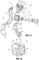
- FIGS. 16 and 17are perspective views of a spindle of the trigger assembly of FIG. 15 in closed and open positions, respectively;
- FIG. 18is an enlarged view of the area of detail indicated as “ 18 ” in FIG. 4 providing a perspective view of a rotation assembly of the instrument of FIG. 1 ;
- FIG. 19is another perspective view of the rotation assembly of FIG. 18 ;
- FIG. 20is an exploded, perspective view of the rotation assembly of FIG. 18 ;
- FIG. 21is an exploded, perspective view of a drive assembly of the instrument of FIG. 1 ;
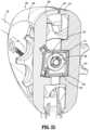
- FIG. 22is a transverse, cross-sectional view taken across section line “ 22 - 22 ” of FIG. 3 ;
- FIG. 24is a transverse, cross-sectional view taken across section line “ 24 - 24 ” of FIG. 3 ;
- FIG. 25is a transverse, cross-sectional view taken across section line “ 25 - 25 ” of FIG. 3 ;
- FIG. 27is a rear, perspective view of the activation assembly of FIG. 26 ;
- FIG. 36is a longitudinal, cross-sectional view of a distal portion of the instrument of FIG. 1 illustrating deployment of the knife assembly;
- the other flag 126 of clevis 120defines an angled distal edge 130 that is angled inwardly, e.g., wherein an outer surface of flag 126 extends further distally as compared to an inner surface thereof with angled distal edge 130 interconnecting the outer and inner surfaces of flag 126 (see FIG. 6 ).
- the outer surfaces of flags 124 , 126 of clevis 120are smooth and continuous, e.g., without interruption from, for example, cam slots, pivot apertures, etc.
- entry of fluids, debris, etc.is inhibited as is catching on or interference by a trocar, other instrument, tissue, debris, etc.
- housing 200 of instrument 10includes first and second housing parts 210 , 220 , e.g., formed from molding, secured to one another, e.g., via ultrasonic welding, to operably support and/or enclose various components of instrument 10 within housing 200 .
- Housing parts 210 , 220may be each be formed from a first shot injection mold and, thereafter, a second shot injection mold may be applied to either or both of housing parts 210 , 220 to, for example, define a non-slip grip surface 260 .
- the second shot injection moldmay flow along a runner system defined within either or both housing parts 210 , 220 to define internal features such as, for example, wire routing features 234 .
- logos and/or other indicia 270may be defined as a cut-out through housing part 210 and/or housing part 220 via the first shot injection mold and, then, may be filled with material via the second shot injection mold to provide contrasting color, texture, etc.
- the second shot injection moldmay define various features associated with housing 200 in a single step, thereby facilitating manufacturing.
- a pivot pin 702is configured to extend through aligned pivot apertures 732 , 772 to pivotably couple jaw members 720 , 760 with one another, while a cam pin 704 is configured for receipt within cam slots 730 , 770 to operably couple jaw members 720 , 760 with one another, e.g., such that translation of cam pin 704 through cam slots 730 , 770 pivots jaw member 720 relative to jaw member 760 .
- Arcuate cam slots 730facilitate smooth and consistent pivoting of jaw member 720 , e.g., inhibiting binding, while longitudinal cam slots 770 facilitate guiding translation of cam pin 704 .
- Distal body portion 725more specifically, define a U-shaped base 734 along the majority of the length thereof; however, distal body portion 725 also includes a pair of spaced-apart fingers 736 extending distally from the distal ends of the uprights of U-shaped base 734 . Unlike U-shaped base 734 , the spaced-apart fingers 736 are not interconnected by a backspan.
- the uprights of U-shaped base 734may include apertures 738 to facilitate overmold retention of insulative jaw body 740 and/or to facilitate manufacture of structural jaw frame 722 .
- structural jaw framesare formed via progressive die stamping (or other suitable stamping process), wherein the structural jaw frame is punched from stock material and bent to achieve the desired configuration.
- Progressive die stampingis advantageous in that it facilitates high volume production.
- Structural jaw frame 722includes features that make difficult if not inhibit utilization of progressive die stamping.
- cam slots 730extend close to the edge of flags 726 , 728 , forming thin sections that are not wide enough for die stamping tools, and, likewise, the spacing between flags 726 , 728 relative to the height of flags 726 , 728 (before bending) is too narrow for die stamping tools.
- structural jaw frame 722may be formed from laser cutting the blanks, wherein structural jaw frame 722 is first cut from sheet stock and/or roller stock using a modulated fiber laser system, e.g., to form cam slots 730 and pivot aperture 732 , among other features, and is then fed to tooling to create the additional features, e.g., bends, coins, etc., thereof.
- a modulated fiber laser systeme.g., to form cam slots 730 and pivot aperture 732 , among other features, and is then fed to tooling to create the additional features, e.g., bends, coins, etc., thereof.
- the laser cutting and formation process for manufacturing structural jaw frame 722may be done in a number of ways such as, for example: the laser cut parts can be singulated, and fed into stage form tooling or transfer tooling (in a manual or automated fashion); the laser cut parts can remain in strips cut to length and fed into stage form tooling, transfer tooling, or progressive tooling (in a manual or automated fashion); or the laser cut parts can remain on a continuous strip and be fed into stage form tooling, transfer tooling, or progressive tooling.
- the structural jaw frame 762 of jaw member 760may be formed in a similar manner as structural jaw frame 722 or may be formed via progressive die stamping (or other suitable stamping process).
- the insulative jaw body 740 , 780 of each jaw member 720 , 760may be formed from one or more overmolds.
- a first overmold of insulative material about the structural jaw frame 722 , 762may be provided to define an insulative insert and, subsequent to positioning of the electrically-conductive plate 750 , 790 thereon, a second overmold may be provided to secure the electrically-conductive plate 750 , 790 to the structural jaw frame 722 , 762 and form an outer housing.
- a single-shot overmoldmay be utilized, a separate insert may be utilized instead of an overmolded insert, etc. As illustrated in FIG.
- electrically-conductive plates 750 , 790are positioned to oppose one another and are electrically-isolated from structural jaw frames 722 , 762 via insulative jaw bodies 740 , 780 , respectively.
- One or both electrically-conductive plate 750 , 790may include a series of stop members 792 configured to maintain a gap between electrically-conductive plates 750 , 790 and inhibit electrical shorting therebetween, e.g., by being formed from an insulative material or by being electrically-isolated from one or both of the electrically-conductive plates 750 , 790 .
- Stop members 792may be the same or different heights and/or the same or different diameters.
- stop members 792need to contact the opposing electrically-conductive plate 750 , 790 to maintain the gap; rather, some stop members 792 may be configured to facilitate gripping tissue. Stop members 792 may be arranged in an asymmetric pattern as illustrated although symmetric configurations are also contemplated.
- Each electrically-conductive plate 750 , 790includes a lead wire 754 , 794 attached thereto and extending proximally therefrom through shaft 100 . More specifically, lead wires 754 , 794 are attached, e.g., soldered, to undersides of electrically-conductive plates 750 , 790 , respectively, and extend proximally through insulative jaw bodies 740 , 780 , proximally therefrom, and into shaft 100 . Lead wires 754 , 794 are disposed on opposite sides of end effector assembly 700 and are positioned exteriorly of proximal flag portions 724 , 764 of jaw members 720 , 760 , respectively.
- Lead wire 754 of jaw member 720extends across, on the interior side thereof, cut-out 128 of flag 124 of clevis 120 , thus enabling movement of lead wire 754 as jaw member 720 is pivoted relative to jaw member 760 and clevis 120 without catching of lead wire 754 on clevis 120 or clevis 120 otherwise constraining the movement of lead wire 754 in response to the pivoting of jaw member 720 .
- Knife channel portions 758 , 798define open proximal ends to permit insertion of knife blade 626 therein and closed distal ends that terminate proximally of the distal ends of electrically-conductive plates 750 , 790 . Knife channel portions 758 , 798 define curved configurations that generally conform to the curvature of jaw members 720 , 760 .
- knife channel portions 758 , 798align with one another to define a full knife channel to facilitate and guide reciprocation of knife blade 626 through jaw members 720 , 760 to cut tissue, e.g., treated tissue, grasped therebetween.
- clevis 120defines weld access apertures 122 through the spaced-apart flags 124 , 126 thereof that facilitate laser welding of the spaced-apart flags 766 , 768 of proximal flag portion 764 of fixed jaw member 760 to flags 124 , 126 of clevis 120 , respectively, on the respective interior sides of flags 124 , 126 of clevis 120 .
- proximal flag portion 764 of fixed jaw member 760captures pivot pin 702 and cam pin 704 between flags 124 , 126 of clevis 120 , thereby securing pivot pin 702 within aligned pivot apertures 732 , 772 of jaw members 720 , 760 and securing cam pin 704 within cam slots 730 , 770 of jaw members 720 , 760 .
- Proximal flag portions 724 , 764 of jaw members 720 , 760cooperate with clevis 120 to define a lockbox configuration, adding lateral stability and support to end effector assembly 700 .
- jaw members 720 , 760are capable of grasping tissue between electrically-conductive plates 750 , 790 thereof.
- Lead wires 754 , 794are adapted to connect to a source of electrosurgical energy, e.g., an electrosurgical generator (not shown), such that, upon activation, electrically-conductive plates 750 , 790 are energized to different potentials to enable the conduction of energy therebetween and through the grasped tissue to treat, e.g., seal, the grasped tissue.
- knife assembly 600includes a knife 610 formed from a distal knife bar 620 and a proximal knife bar 630 .
- Knife assembly 600further includes a spindle pin 640 and tube plug 650 associated with proximal knife bar 630 .
- Knife 610is selectively translatable, in response to actuation of trigger assembly 500 ( FIG. 4 ) between a retracted position (see FIG. 32 ), wherein knife blade 626 of knife 610 is positioned proximally of electrically-conductive plates 750 , 790 of jaw members 720 , 760 , respectively, and an extended position (see FIG. 36 ), wherein knife blade 626 of knife 610 extends distally through knife channel portions 758 , 798 of jaw members 720 , 760 , respectively, to cut tissue, e.g., treated tissue, grasped therebetween.
- Distal knife bar 620is formed by an etching process (or in any other suitable manner) and includes a body 622 defining a longitudinally-extending cut-out 624 and a knife blade 626 at a distal end thereof, distally of longitudinally-extending cut-out 624 .
- a proximal end portion of body 622 of distal knife bar 620overlaps a distal end portion of proximal knife bar 630 in side-by-side arrangement to enable securement therebetween, e.g., via laser welding.
- a laser weld aperture 623may be defined through body 622 to facilitate such securement.
- a weld aperturemay be defined through proximal knife bar 630 for similar purposes.
- Knife blade 626defines an etched distal cutting edge 628 that may define a generally arrow-shaped configuration wherein first and second angled cutting edges 629 a angle proximally from a distal apex 629 b .
- Distal cutting edge 628may be formed via etching on one side of knife blade 626 or both sides thereof and is sharp to facilitate cutting through tissue upon translation of knife blade 626 to the extended position.
- Proximal knife bar 630is formed by a stamping process (or in any other suitable manner, similar or different from the formation of distal knife bar 620 ) and, as noted above, defines a distal end portion that overlaps the proximal end portion of body 622 of distal knife bar 620 in side-by-side arrangement to enable securement therebetween, e.g., via laser welding.
- Proximal knife bar 630is configured for slidable receipt within tube plug 650 and includes a proximal aperture 632 configured for receipt of spindle pin 640 transversely therethrough.
- Spring pin 640extends transversely through and outwardly from either side of a longitudinal slot 652 defined within tube plug 650 . Longitudinal slot 652 define a suitable length to accommodate translation of spindle pin 640 relative to tube plug 650 to actuate knife blade 626 between the retracted and extended positions.
- Tube plug 650is configured for slidable receipt within proximal drive sleeve 360 of drive assembly 300 and servers to maintain the position and orientation of knife 610 therein (see FIGS. 30 and 33 ).
- Tube plug 650further includes one or more wire guide channels 654 on either side thereof to guide lead wires 754 , 794 through proximal drive sleeve 360 to end effector assembly 700 .
- Tube plug 650also serves to substantially inhibit fluid within proximal drive sleeve 360 from passing proximally beyond tube plug 650 and into housing 200 .
- drive assembly 300is includes a movable handle 310 , a linkage 320 , a carriage 330 , a nested spring assembly 340 , a return spring 350 , a proximal drive sleeve 360 , a distal drive frame 370 , a sliding collar 380 , first and second fixed (relative to drive sleeve 360 ) collars 392 and 394 , respectively, and a proximal stop collar 396 .
- Movable handle 310includes a body 312 disposed within housing 200 and having pivot bosses 314 extending transversely outwardly from either side thereof.
- Body 312is pivotably coupled to housing 200 within housing 200 via receipt of pivot bosses 314 within movable handle pivot recesses 248 of housing parts 210 , 220 .
- Movable handle 310further includes a grasping portion 318 that depends from body 312 and extends from housing 200 through movable handle and trigger slot 240 to enable manual manipulation by a user.
- Movable handle 310is pivotable relative to housing 200 between an un-actuated position ( FIG. 28 ), wherein grasping portion 318 of movable handle 310 is farther spaced-apart from fixed handle portion 290 of housing 200 , an actuated position ( FIG. 31 ), wherein grasping portion 318 is more closely approximated relative to fixed handle portion 290 of housing 200 , and an activation position ( FIG.
- Movable handle 310also includes first and second spaced-apart knife lockout protrusions 316 , 317 protruding distally from body 312 and grasping portion 318 , respectively.
- Linkage 320is disposed within housing 200 , pivotably coupled to body 312 of movable handle 310 at a distal end portion thereof, and pivotably coupled to carriage 330 at a proximal end portion thereof. In this manner, pivoting of movable handle 310 from the un-actuated position towards the actuated position urges linkage 320 proximally and also pivots linkage 320 from a more-angled orientation to a more-longitudinal orientation.
- Carriage 330is slidably received within body portion 280 of housing 200 and, more specifically, includes bosses 332 extending outwardly from either side thereof that are received within guide tracks 246 of housing 200 to guide translation of carriage 330 through and relative to body portion 280 of housing 200 .
- Carriage 330includes a body 334 defining a seat 336 , and a bifurcated neck 338 extending upwardly from body 334 at a proximal end portion thereof on either side of proximal drive sleeve 360 , which extends through carriage 330 .
- First fixed collar 392is fixed about proximal drive sleeve 360 , e.g., via keyed engagement, and is positioned distally of bifurcated neck 338 of carriage 330 to define a distal stop to sliding of carriage 330 about drive sleeve 360 .
- Sliding collar 380is slidably disposed about proximal drive sleeve 360 and is positioned within seat 336 proximally of bifurcated neck 338 .
- Nested spring assembly 340including an outer compression spring 342 and an inner compression spring 344 nested within outer compression spring 342 , is also seated within seat 336 and positioned proximally of sliding collar 380 .
- Inner and outer compression springs 342 , 344are slidably disposed about proximal drive sleeve 360 .
- Second fixed collar 394is fixed about proximal drive sleeve 360 , e.g., via keyed engagement, and is positioned proximally of nested spring assembly 340 .
- Proximal stop collar 396is fixed within housing 200 and slidable about a proximal end portion of proximal drive sleeve 360 .
- Proximal stop collar 396may be slidably engaged within a keyway defined within proximal drive sleeve 360 or may be coupled thereto in any other suitable manner.
- Return spring 350may be a conical spring and is disposed about proximal drive sleeve 360 between second fixed collar 394 and proximal stop collar 396 .
- Proximal drive sleeve 360defines opposed longitudinally-extending slots 364 defined therethrough to enable spindle pin 640 to extend through and outwardly from either side of proximal drive sleeve 360 while still enabling relative sliding of proximal drive sleeve 360 and spindle pin 640 relative to one another.
- Spindle pin 640also extends through opposed longitudinally-extending slots 112 of shaft 100 and outwardly from either side thereof. Slots 112 , 364 at least partially overlap regardless of the relative position between proximal drive sleeve 360 and shaft 100 such that spindle pin 640 is not interfered with.
- Slots 112 , 364also provide a passage for lead wires 754 , 794 to extend therethrough, enabling lead wires 754 , 794 to extend from rotation assembly 400 (external of shaft 100 and proximal drive sleeve 360 ) through slots 112 , 364 and into proximal drive sleeve 360 (which is disposed within shaft 100 ). As slots 112 , 364 at least partially overlap regardless of the relative position between proximal drive sleeve 360 and shaft 100 , lead wires 754 , 794 are likewise not interfered with.
- trigger 510in use, and initially with movable handle 310 in the un-actuated position corresponding to the spaced-apart position of jaw members 720 , 760 , trigger 510 is disposed in an un-actuated position corresponding to the retracted position of knife 610 (see FIGS. 28 and 29 ). In this position, knife lockout protrusions 316 , 317 of movable handle 310 are positioned adjacent to and/or in contact with trigger 510 at spaced-apart positions along the height of trigger 510 .
- trigger 510With movable handle 310 in the actuated position ( FIG. 31 ) (or the activated position ( FIG. 34 )) and, thus, jaw members 720 , 760 disposed in the approximated position ( FIG. 32 ), trigger 510 is permitted to be actuated.
- finger tab 514 of trigger 510is pivoted proximally towards movable handle 310 . Proximal pivoting of finger tab 514 pivots body 512 of trigger 510 distally since body 512 and finger tab 514 are on opposite sides of the pivot connecting trigger 510 with housing 200 .
- Distal pivoting of body 512 of trigger 510urges crossbar 524 of rocker 520 distally.
- linkage 530is pivoted distally about second end 536 thereof.
- the distal movement of crossbar 524 of rocker 520pulls upright 522 of rocker 520 distally and pivots upright 522 relative to spindle housing 540 .
- the distal pulling of upright 522pulls spindle housing 540 distally along shaft 100 such that spindle pin 640 is translated distally through slots 112 , 364 to thereby advance knife 610 distally from the retracted position to the extended position wherein, as shown in FIG.
- rotation assembly 400includes a rotation wheel 410 and a continuous rotation assembly 420 .
- Rotation wheel 410includes a body 412 and a keyed central aperture 414 extending through body 412 . Keyed central aperture 414 is configured to receive shaft 100 therethrough and engage proximal cut-out 114 of shaft 110 to thereby fixedly mount rotation wheel 410 about shaft 100 .
- Rotation wheel 410also includes a plurality of flutes 416 arranged annularly about an annular periphery thereof.
- Rotation wheel 410protrudes outwardly through rotation wheel windows 242 defined within housing 200 , such that flutes 416 may be manually manipulated by a user to rotation rotate wheel 410 relative to housing 200 from either side of housing 200 .
- Rotation wheel 410is rotatable continuously in either direction without limitation, e.g., infinitely in either direction.
- Rotation of rotation wheel 410rotates shaft 100 relative to housing 200 and, via the interconnections therebetween, also effects rotation of distal tube guide 150 , proximal drive sleeve 360 , distal drive frame 370 , end effector assembly 700 , and knife assembly 600 relative to housing 200 in conjunction with the rotation of shaft 100 and rotation wheel 410 .
- end effector assembly 700may be positioned in a desired orientation to facilitate grasping, treating, and/or dividing tissue.
- Rotation wheel 410further defines a proximally-facing recess 418 (see FIGS. 30 and 33 ) and a pair of pass-through connector slots 419 .
- Pass-through connector slots 419are configured to receive lead connectors 755 , 795 secured at the proximal ends of lead wires 754 , 794 , respectively, and electrically coupled thereto.
- Lead wires 754 , 794extend from lead connectors 755 , 795 , into shaft 100 and proximal drive sleeve 360 , distally through proximal drive sleeve 360 , about distal drive frame 370 , and to jaw members 720 , 760 for electrically coupling with electrically-conductive plates 750 , 790 , respectively, as detailed above.
- the entireties of lead wires 754 , 794are rotatable in conjunction with the rotation of rotation wheel 410 .
- Continuous rotation assembly 420includes a body 422 , an inner contact ring 424 including an electrical connector 425 extending therefrom, an outer contact ring 426 including an electrical connector 427 extending therefrom, and first and second spring contacts 432 , 434 each including a respective electrical connector 433 , 435 extending therefrom.
- Body 422is configured for rotatable engagement with rotation wheel 410 , e.g., enabling rotation of rotation wheel 410 about body 422 and relative to housing 200 , and includes a disc 436 and a frame 438 monolithically formed as a single piece, although other configurations are also contemplated.
- Disc 436includes an outer rim 440 and a distally-facing surface 442 recessed relative to outer rim 440 .
- Outer rim 440 of disc 436is configured for rotatable receipt within proximally-facing recess 418 of rotation wheel 410 , e.g., in snap-fit rotation engagement, such that a cavity is defined between distally-facing surface 442 of disc 436 and the recessed surface of proximally-facing recess 418 of rotation wheel 410 .
- Frame 438is configured to be fixedly captured within housing 200 (See FIG. 25 ) to thereby fix body 422 within and relative to housing 200 .
- rotation wheel 410is rotatable relative to body 422 and housing 200 .
- Body 422further defines a central aperture 446 configured to rotatably receive shaft 100 , and a pair of pass-through connector slots 448 .
- rotation wheel 410is rotatable relative to body 422 and housing 200 .
- Inner and outer contact rings 424 , 426are disposed within the cavity defined between disc 436 and rotation wheel 410 and, more specifically, are fixed relative on and relative to the recessed surface of proximally-facing recess 418 of rotation wheel 410 with electrical connectors 425 , 426 , respectively, thereof extending into pass-through connector slots 419 to engage and electrically couple with lead connectors 755 , 795 of lead wires 754 , 794 , respectively.
- Connectors 425 , 426 and connectors 755 , 795may be male-female slide connectors configured to slide and lock into engagement and electrical coupling with one another, without the need for tools, soldering, etc.
- the connection between connectors 425 , 426 and connectors 755 , 795respectively, electrically couples lead wires 754 , 795 with inner and outer contact rings 424 , 426 , respectively.
- First and second spring contacts 432 , 434are fixedly secured to body 422 and, thus, housing 200 , at least via receipt of electrical connectors 433 , 435 of spring contacts 432 , 434 , respectively, within pass-through connector slots 448 .
- Electrical connectors 433 , 435are configured to slide and lock into engagement and electrical coupling with corresponding lead connectors 912 , 922 of lead wires 910 , 920 , e.g., as male-female connectors detailed above.
- Lead wires 910 , 920are routed through housing 200 to activation assembly 800 , which, in turn, is in electrical communication with wires associated with cable 900 to connect to the energy source, e.g., an electrosurgical generator (not shown), via plug 940 of cable 900 (see FIG. 1 ).
- the portions of lead wires 910 , 920 extending within housing 200are entirely stationary regardless of rotation of rotation wheel 410 .
- First and second spring contacts 432 , 434are biased into contact with inner and outer contact rings 424 , 426 , respectively. More specifically, first and second spring contacts 432 , 434 maintain contact with inner and outer contact rings 424 , 426 , respectively, regardless of the rotational orientation of rotation wheel 410 relative to body 422 , thus maintaining electrical connection and permitting continuous, e.g., infinite, rotation of rotation wheel 410 in either direction relative to body 422 and housing 200 .
- first and second spring contacts 432 , 434 and inner and outer contact rings 424 , 426respectively, electrically connects lead wires 910 , 920 with lead wires 754 , 794 , thus enabling the conduction of energy, e.g., electrosurgical energy, from the generator to electrically-conductive plates 750 , 790 of jaw members 720 , 760 , respectively, for treating tissue grasped therebetween (see FIGS. 7 - 9 ).
- energye.g., electrosurgical energy
- activation assembly 800is disposed within fixed handle portion 290 of housing 200 and includes an activation button 810 and a circuit board 820 .
- Activation button 810protrudes distally through activation button aperture 236 of housing 200 while circuit board 820 is retained within board support 238 of housing 200 .
- Activation button 810includes an internal electrical switch and is mounted on circuit board 820 such that the electrical switch thereof is in selective electrical communication with electrical trace 822 of circuit board 820 .
- movable handle 310is pivotable relative to housing 200 between the un-actuated position ( FIG. 28 ), the actuated position ( FIG. 31 ), and the activation position ( FIG. 34 ).
- grasping portion 318 of movable handle 310is urged into contact with the exposed portion of activation button 810 to activate activation button 810 of activation assembly 800 , e.g., to establish or break electrical connection via the switch of activation button 810 .
- Electrical trace 822extends along circuit board 820 from activation button 810 to connectors 832 disposed on circuit board 820 .
- Another electrical trace 824is connected to connector 834 on circuit board 820 .
- Connectors 832 , 834may be male or female slide connectors, similarly as detailed above, configured to electrical couple with lead wires 910 , 920 ( FIG. 19 ), respectively.
- Circuit board 820further includes plural contacts to which the wires of cable 900 are attached, e.g., soldered, to thereby electrically couple circuit board 820 with the energy source, e.g., an electrosurgical generator (not shown), via plug 940 of cable 900 (see FIG. 1 ), and to thereby selectively electrically couple lead wires 910 , 920 ( FIG. 19 ) with the energy source.
- the energy sourcee.g., an electrosurgical generator (not shown)
- the establishment or breaking of electrical connection via the switch of activation button 910can be detected at the generator via monitoring at least one of the wires connected, e.g., soldered, to circuit board 820 .
- the generatorcan readily determine when activation button 810 has been activated and, in response thereto, initiate the supply of energy through wires of cable 900 to circuit board 820 and, thus, to lead wires 910 , 920 ( FIG. 19 ) to energize electrically-conductive plates 750 , 790 of jaw members 720 , 760 , respectively, for treating tissue grasped therebetween.
- Instrument 1010is similar to instrument 10 ( FIG. 1 ) and may include any of the features thereof except as explicitly contradicted below. Accordingly, only differences between instrument 1010 and instrument 10 ( FIG. 1 ) are detailed below.
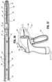
- Instrument 1010includes a latching mechanism 1020 configured to lock movable handle 1310 in the actuated positon, thereby latching the jaw members thereof (not shown, the same as jaw members 720 , 760 of instrument 10 ( FIG. 1 )) in the approximated position. Further, activation assembly 1800 of instrument 1010 is relocated to the rear of body portion 1280 of housing 1200 to enable selective activation by a finger of a user rather than by movable handle 1310 , although other positions and/or configurations of activation assembly 1800 are also contemplated.
- Latching mechanism 1020 of instrument 1010includes a latch arm 1030 coupled to movable handle 1310 and a latch track 1050 disposed within, e.g., defined within one (or both) of the housing parts 1210 , 1220 of housing 1200 , although the reverse configuration is also contemplated.
- Latch arm 1030is monolithically formed as a single piece, e.g., via molding, and includes an engagement hook 1032 defined at a first end portion thereof and a transverse latch post 1034 protruding from one (or both) sides of latch arm 1030 at a second, opposite end portion thereof.
- Latch arm 1030is flexible, enabling deflection of transverse latch post 1034 relative to engagement hook 1032 about at least two axes.
- Engagement hook 1032 of latch arm 1030defines a notch 1036 and a mouth 1038 providing access to notch 1036 .
- Notch 1036is circumferentially surrounded by engagement hook 1032 about at least 270 degrees of a circumference of notch 1036 .
- Engagement hook 1032is configured for snap-fit engagement about a latch boss 1319 of movable handle 1310 with latch boss 1319 passing through mouth 1038 and into engagement within notch 1036 wherein engagement hook 1032 provides at least 270 degrees of retention about latch boss 1319 .
- engagement hook 1032can be readily engaged and maintained in engagement about latch boss 1319 .
- Latch boss 1319may be monolithically formed with movable handle 1310 .
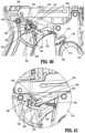
- Latch track 1050 of latching mechanism 1020defines a tortuous path about a central block 1052 , an upper guide rail 1054 , a lower guide rail 1056 , and a rear guide leg 1058 .
- Latch track 1050more specifically, includes an entry path 1062 defined between central block 1052 and lower guide rail 1056 , a latching path 1064 defined around central block 1052 between lower guide rail 1056 and rear guide leg 1058 and interconnecting entry path 1062 with a saddle 1066 defined within central block 1052 , an unlatching path 1068 defined around central block 1052 between rear guide leg 1058 and upper guide rail 1054 and interconnecting saddle 1066 with a return path 1070 , and return path 1070 defined between central block 1052 and upper guide rail 1054 .
- Return path 1070includes a transverse ramp 1080 that, as detailed below, includes a proximal ramped end 1082 and a distal cliff end 1084 .
- transverse latch post 1034in use, upon pivoting of movable handle 1310 from the un-actuated position towards the actuated position, transverse latch post 1034 is moved proximally towards latch track 1050 . Upon further pivoting of movable handle 1310 towards the actuated position, transverse latch post 1034 enters entry path 1062 and travels distally therethrough between central block 1052 and lower guide rail 1056 . Latch arm 1030 is deflected, e.g., about a first axis, downwardly to enable transverse latch post 1034 to travel through entry path 1062 .
- transverse latch post 1034excursion of transverse latch post 1034 into return path 1070 is inhibited by distal cliff end 1084 ; that is, transverse latch post 1034 is inhibited from climbing distal cliff end 1084 and, thus, is inhibited from entering return path 1070 , thereby ensuring that transverse latch post 1034 correctly follows entry path 1062 .
- Movable handle 1310is further pivoted proximally to and beyond the actuated position to an over-actuated position to enable transverse latch post 1034 to clear central block 1052 .
- transverse latch post 1034clears central block 1052 and, thus, latch arm 1030 is no longer held in a deflected position thereby, latch arm 1030 is resiliently returned upwardly such that transverse latch post 1034 is urged towards or into contact with rear guide leg 1058 . This may be confirmed by audible and/or tactile feedback.
- movable handle 1310may be released (or returned), allowing movable handle 1310 to return distally back towards the actuated position under the bias of the return spring (not shown, the same as return spring 350 ( FIGS. 2 and 3 ).
- transverse latch post 1034is moved distally through latching path 1064 and into saddle 1066 defined within central block 1052 , thereby latching movable handle 1310 in the actuated position.
- the jaw members of instrument 1010are correspondingly locked in the approximated position applying an appropriate jaw force to tissue grasped therebetween such that the jaw members may be energized to treat, e.g., seal, tissue grasped therebetween.
- movable handle 1310In order to release movable handle 1310 from the latched condition and enable return of the jaw members to the spaced-apart position, e.g., after tissue treatment and/or cutting, or to re-grasp tissue, movable handle 1310 is again pivoted proximally from the actuated position to the over-actuated position.
- transverse latch post 1034When movable handle 1310 is pivoted to the over-actuated position, transverse latch post 1034 is moved proximally from saddle 1066 through the unlatching path 1068 to clear central block 1052 , thus allowing latch arm 1030 to further resiliently return upwardly such that transverse latch post 1034 is urged towards or into contact with upper guide rail 1054 .
- movable handle 1310may be released (or returned), allowing movable handle 1310 to return distally. This distal return of movable handle 1310 pulls transverse latch post 1034 distally through return path 1070 , between upper guide rail 1054 and central block 1052 .
- transverse latch post 1034As transverse latch post 1034 is moved distally through return path 1070 , transverse latch post 1034 ramps over proximal ramped end 1082 of transverse ramp 1080 and along transverse ramp 1080 , thereby increasingly deflecting latch arm 1030 transversely (e.g., about a second axis) until transverse latch post 1034 falls off distal cliff end 1084 of transverse ramp 1080 , allowing latch arm 1030 to resiliently return transversely.
- transverse latch post 1034falls off distal cliff end 1084 of transverse ramp 1080 , proximal return of transverse latch post 1034 through return path 1070 is inhibited and, thus, re-actuation of movable handle 1310 thereafter moves transverse latch post 1034 along entry path 1062 .
- movable handle 1310continues to return distally towards the un-actuated position, allowing transverse latch post 1034 to clear latch track 1050 and allowing latch arm 1030 to return to its initial position corresponding to the un-actuated position of movable handle 1310 .
Landscapes
- Health & Medical Sciences (AREA)
- Life Sciences & Earth Sciences (AREA)
- Surgery (AREA)
- Engineering & Computer Science (AREA)
- Medical Informatics (AREA)
- Veterinary Medicine (AREA)
- Biomedical Technology (AREA)
- Heart & Thoracic Surgery (AREA)
- Nuclear Medicine, Radiotherapy & Molecular Imaging (AREA)
- Molecular Biology (AREA)
- Animal Behavior & Ethology (AREA)
- General Health & Medical Sciences (AREA)
- Public Health (AREA)
- Physics & Mathematics (AREA)
- Plasma & Fusion (AREA)
- Otolaryngology (AREA)
- Ophthalmology & Optometry (AREA)
- Surgical Instruments (AREA)
Abstract
Description
Claims (20)
Priority Applications (3)
| Application Number | Priority Date | Filing Date | Title |
|---|---|---|---|
| US17/122,113US12343065B2 (en) | 2020-12-15 | 2020-12-15 | Energy-based surgical instrument for grasping, treating, and/or dividing tissue |
| PCT/US2021/063323WO2022132779A1 (en) | 2020-12-15 | 2021-12-14 | Energy-based surgical instrument for grasping, treating, and/or dividing tissue |
| EP21840355.8AEP4262602A1 (en) | 2020-12-15 | 2021-12-14 | Energy-based surgical instrument for grasping, treating, and/or dividing tissue |
Applications Claiming Priority (1)
| Application Number | Priority Date | Filing Date | Title |
|---|---|---|---|
| US17/122,113US12343065B2 (en) | 2020-12-15 | 2020-12-15 | Energy-based surgical instrument for grasping, treating, and/or dividing tissue |
Related Child Applications (1)
| Application Number | Title | Priority Date | Filing Date |
|---|---|---|---|
| US19/249,196ContinuationUS20250318867A1 (en) | 2025-06-25 | Energy-based surgical instrument for grasping, treating, and/or dividing tissue |
Publications (2)
| Publication Number | Publication Date |
|---|---|
| US20220183745A1 US20220183745A1 (en) | 2022-06-16 |
| US12343065B2true US12343065B2 (en) | 2025-07-01 |
Family
ID=81943579
Family Applications (1)
| Application Number | Title | Priority Date | Filing Date |
|---|---|---|---|
| US17/122,113Active2042-07-19US12343065B2 (en) | 2020-12-15 | 2020-12-15 | Energy-based surgical instrument for grasping, treating, and/or dividing tissue |
Country Status (1)
| Country | Link |
|---|---|
| US (1) | US12343065B2 (en) |
Families Citing this family (2)
| Publication number | Priority date | Publication date | Assignee | Title |
|---|---|---|---|---|
| WO2024206764A1 (en)* | 2023-03-31 | 2024-10-03 | Covidien Lp | Energy-based surgical instrument for grasping, treating and dividing tissue with a consistent closure force |
| WO2025062349A1 (en)* | 2023-09-21 | 2025-03-27 | Covidien Lp | Actuation mechanism for surgical instruments and surgical instruments incorporating the same |
Citations (184)
| Publication number | Priority date | Publication date | Assignee | Title |
|---|---|---|---|---|
| US3100489A (en) | 1957-09-30 | 1963-08-13 | Medtronic Inc | Cautery device |
| USD249549S (en) | 1976-10-22 | 1978-09-19 | Aspen Laboratories, Inc. | Electrosurgical handle |
| USD263020S (en) | 1980-01-22 | 1982-02-16 | Rau Iii David M | Retractable knife |
| US4461297A (en) | 1981-03-19 | 1984-07-24 | Holzhaur und Sutter Medizin-technische Gerate und Instrumente GmbH | Forceps |
| US4461305A (en) | 1981-09-04 | 1984-07-24 | Cibley Leonard J | Automated biopsy device |
| USD295893S (en) | 1985-09-25 | 1988-05-24 | Acme United Corporation | Disposable surgical clamp |
| USD295894S (en) | 1985-09-26 | 1988-05-24 | Acme United Corporation | Disposable surgical scissors |
| USD298353S (en) | 1986-05-06 | 1988-11-01 | Vitalmetrics, Inc. | Handle for surgical instrument |
| USD299413S (en) | 1985-07-17 | 1989-01-17 | The Stanley Works | Folding pocket saw handle |
| US5122139A (en) | 1989-11-13 | 1992-06-16 | Select-Medizintechnik Hermann Sutter Gmbh | Medical coagulation instrument |
| US5201743A (en) | 1992-05-05 | 1993-04-13 | Habley Medical Technology Corp. | Axially extendable endoscopic surgical instrument |
| US5211655A (en) | 1992-05-08 | 1993-05-18 | Hasson Harrith M | Multiple use forceps for endoscopy |
| US5254117A (en)* | 1992-03-17 | 1993-10-19 | Alton Dean Medical | Multi-functional endoscopic probe apparatus |
| USD343453S (en) | 1993-05-05 | 1994-01-18 | Laparomed Corporation | Handle for laparoscopic surgical instrument |
| USD348930S (en) | 1991-10-11 | 1994-07-19 | Ethicon, Inc. | Endoscopic stapler |
| USD349341S (en) | 1992-10-28 | 1994-08-02 | Microsurge, Inc. | Endoscopic grasper |
| USD354564S (en) | 1993-06-25 | 1995-01-17 | Richard-Allan Medical Industries, Inc. | Surgical clip applier |
| US5383875A (en) | 1994-05-31 | 1995-01-24 | Zimmer, Inc. | Safety device for a powered surgical instrument |
| USD358887S (en) | 1993-12-02 | 1995-05-30 | Cobot Medical Corporation | Combined cutting and coagulating forceps |
| US5454827A (en) | 1994-05-24 | 1995-10-03 | Aust; Gilbert M. | Surgical instrument |
| US5478351A (en) | 1992-06-24 | 1995-12-26 | Microsurge, Inc. | Endoscopic surgical tool with handle and detachable tool assembly |
| US5512721A (en) | 1993-09-28 | 1996-04-30 | Unisurge, Inc. | Autoclavable electrical switch assembly for use with a medical device and medical device using the same |
| US5601601A (en) | 1991-12-13 | 1997-02-11 | Unisurge Holdings, Inc. | Hand held surgical device |
| USD384413S (en) | 1994-10-07 | 1997-09-30 | United States Surgical Corporation | Endoscopic suturing instrument |
| US5746739A (en) | 1994-11-10 | 1998-05-05 | Select Medizin-Technik Hermann Sutter Gmbh | Bipolar coagulation forceps with rinsing tube |
| USH1745H (en) | 1995-09-29 | 1998-08-04 | Paraschac; Joseph F. | Electrosurgical clamping device with insulation limited bipolar electrode |
| USD402028S (en) | 1997-10-10 | 1998-12-01 | Invasatec, Inc. | Hand controller for medical system |
| US5849022A (en) | 1994-07-29 | 1998-12-15 | Olympus Optical Co., Ltd. | Medical instrument for use in combination with endoscopes |
| US5891142A (en) | 1996-12-06 | 1999-04-06 | Eggers & Associates, Inc. | Electrosurgical forceps |
| US5891140A (en) | 1996-12-23 | 1999-04-06 | Cardiothoracic Systems, Inc. | Electrosurgical device for harvesting a vessel especially the internal mammary artery for coronary artery bypass grafting |
| USD408018S (en) | 1996-03-12 | 1999-04-13 | Mcnaughton Patrick J | Switch guard |
| US5954736A (en) | 1997-10-10 | 1999-09-21 | Ethicon Endo-Surgery, Inc. | Coagulator apparatus having indexed rotational positioning |
| USD416089S (en) | 1996-04-08 | 1999-11-02 | Richard-Allan Medical Industries, Inc. | Endoscopic linear stapling and dividing surgical instrument |
| US6010516A (en) | 1998-03-20 | 2000-01-04 | Hulka; Jaroslav F. | Bipolar coaptation clamps |
| USD424694S (en) | 1998-10-23 | 2000-05-09 | Sherwood Services Ag | Forceps |
| USD425201S (en) | 1998-10-23 | 2000-05-16 | Sherwood Services Ag | Disposable electrode assembly |
| US6106542A (en) | 1998-01-23 | 2000-08-22 | Microsurgical Laboratories, Inc. | Surgical forceps |
| US6117158A (en) | 1999-07-07 | 2000-09-12 | Ethicon Endo-Surgery, Inc. | Ratchet release mechanism for hand held instruments |
| USH1904H (en) | 1997-05-14 | 2000-10-03 | Ethicon Endo-Surgery, Inc. | Electrosurgical hemostatic method and device |
| USD449886S1 (en) | 1998-10-23 | 2001-10-30 | Sherwood Services Ag | Forceps with disposable electrode |
| USD453923S1 (en) | 2000-11-16 | 2002-02-26 | Carling Technologies, Inc. | Electrical rocker switch guard |
| USD454951S1 (en) | 2001-02-27 | 2002-03-26 | Visionary Biomedical, Inc. | Steerable catheter |
| USD457958S1 (en) | 2001-04-06 | 2002-05-28 | Sherwood Services Ag | Vessel sealer and divider |
| USD457959S1 (en) | 2001-04-06 | 2002-05-28 | Sherwood Services Ag | Vessel sealer |
| USH2037H1 (en) | 1997-05-14 | 2002-07-02 | David C. Yates | Electrosurgical hemostatic device including an anvil |
| USD465281S1 (en) | 1999-09-21 | 2002-11-05 | Karl Storz Gmbh & Co. Kg | Endoscopic medical instrument |
| USD466209S1 (en) | 2001-02-27 | 2002-11-26 | Visionary Biomedical, Inc. | Steerable catheter |
| US20020188294A1 (en) | 2001-04-06 | 2002-12-12 | Couture Gary M. | Vessel sealer and divider |
| US20030018331A1 (en) | 2001-04-06 | 2003-01-23 | Dycus Sean T. | Vessel sealer and divider |
| US20030109875A1 (en) | 1999-10-22 | 2003-06-12 | Tetzlaff Philip M. | Open vessel sealing forceps with disposable electrodes |
| US20030171747A1 (en) | 1999-01-25 | 2003-09-11 | Olympus Optical Co., Ltd. | Medical treatment instrument |
| US20030229344A1 (en) | 2002-01-22 | 2003-12-11 | Dycus Sean T. | Vessel sealer and divider and method of manufacturing same |
| US20040082952A1 (en) | 2001-04-06 | 2004-04-29 | Dycus Sean T. | Vessel sealer and divider |
| US20040116952A1 (en) | 1999-03-05 | 2004-06-17 | Olympus Optical Co., Ltd. | Surgical apparatus permitting recharge of battery-driven surgical instrument in noncontact state |
| USD493888S1 (en) | 2003-02-04 | 2004-08-03 | Sherwood Services Ag | Electrosurgical pencil with pistol grip |
| US20040176762A1 (en) | 1997-11-12 | 2004-09-09 | Lawes Kate R. | Electrosurgical instrument reducing flashover |
| USD496997S1 (en) | 2003-05-15 | 2004-10-05 | Sherwood Services Ag | Vessel sealer and divider |
| USD499181S1 (en) | 2003-05-15 | 2004-11-30 | Sherwood Services Ag | Handle for a vessel sealer and divider |
| US20040243125A1 (en) | 2001-04-06 | 2004-12-02 | Sean Dycus | Vessel sealer and divider |
| USD502994S1 (en) | 2003-05-21 | 2005-03-15 | Blake, Iii Joseph W | Repeating multi-clip applier |
| US20050154387A1 (en) | 2003-11-19 | 2005-07-14 | Moses Michael C. | Open vessel sealing instrument with hourglass cutting mechanism and over-ratchet safety |
| USD509297S1 (en) | 2003-10-17 | 2005-09-06 | Tyco Healthcare Group, Lp | Surgical instrument |
| USD525361S1 (en) | 2004-10-06 | 2006-07-18 | Sherwood Services Ag | Hemostat style elongated dissecting and dividing instrument |
| US7083613B2 (en) | 1997-03-05 | 2006-08-01 | The Trustees Of Columbia University In The City Of New York | Ringed forceps |
| USD531311S1 (en) | 2004-10-06 | 2006-10-31 | Sherwood Services Ag | Pistol grip style elongated dissecting and dividing instrument |
| USD533274S1 (en) | 2004-10-12 | 2006-12-05 | Allegiance Corporation | Handle for surgical suction-irrigation device |
| USD533942S1 (en) | 2004-06-30 | 2006-12-19 | Sherwood Services Ag | Open vessel sealer with mechanical cutter |
| USD535027S1 (en) | 2004-10-06 | 2007-01-09 | Sherwood Services Ag | Low profile vessel sealing and cutting mechanism |
| US7166106B2 (en) | 2001-06-05 | 2007-01-23 | Erbe Elektromedizin Gmbh | Bipolar clamp |
| USD538932S1 (en) | 2005-06-30 | 2007-03-20 | Medical Action Industries Inc. | Surgical needle holder |
| USD541418S1 (en) | 2004-10-06 | 2007-04-24 | Sherwood Services Ag | Lung sealing device |
| USD541938S1 (en) | 2004-04-09 | 2007-05-01 | Sherwood Services Ag | Open vessel sealer with mechanical cutter |
| USD541611S1 (en) | 2006-01-26 | 2007-05-01 | Robert Bosch Gmbh | Cordless screwdriver |
| USD545432S1 (en) | 2003-08-08 | 2007-06-26 | Olympus Corporation | Distal portion of hemostatic forceps for endoscope |
| USD547154S1 (en) | 2006-09-08 | 2007-07-24 | Winsource Industries Limited | Rotary driving tool |
| US20070260241A1 (en) | 2006-05-04 | 2007-11-08 | Sherwood Services Ag | Open vessel sealing forceps disposable handswitch |
| US20080009860A1 (en) | 2006-07-07 | 2008-01-10 | Sherwood Services Ag | System and method for controlling electrode gap during tissue sealing |
| USD564662S1 (en) | 2004-10-13 | 2008-03-18 | Sherwood Services Ag | Hourglass-shaped knife for electrosurgical forceps |
| USD567943S1 (en) | 2004-10-08 | 2008-04-29 | Sherwood Services Ag | Over-ratchet safety for a vessel sealing instrument |
| USD575401S1 (en) | 2007-06-12 | 2008-08-19 | Tyco Healthcare Group Lp | Vessel sealer |
| USD575395S1 (en) | 2007-02-15 | 2008-08-19 | Tyco Healthcare Group Lp | Hemostat style elongated dissecting and dividing instrument |
| US20080215048A1 (en) | 2005-10-04 | 2008-09-04 | Dieter Hafner | Electrosurgical Instrument |
| US20080262491A1 (en) | 2004-08-10 | 2008-10-23 | Medtronic, Inc. | Tuna Device with Integrated Saline Reservoir |
| USD582038S1 (en) | 2004-10-13 | 2008-12-02 | Medtronic, Inc. | Transurethral needle ablation device |
| US20090088792A1 (en) | 2007-10-02 | 2009-04-02 | Tyco Healthcare Group Lp | Articulating Surgical Instrument |
| US7628791B2 (en) | 2005-08-19 | 2009-12-08 | Covidien Ag | Single action tissue sealer |
| US20100030205A1 (en) | 1999-01-21 | 2010-02-04 | Herzon Garrett D | Thermal cautery surgical forceps |
| USD617903S1 (en) | 2009-05-13 | 2010-06-15 | Tyco Healthcare Group Lp | End effector pointed tip |
| USD617901S1 (en) | 2009-05-13 | 2010-06-15 | Tyco Healthcare Group Lp | End effector chamfered tip |
| USD617900S1 (en) | 2009-05-13 | 2010-06-15 | Tyco Healthcare Group Lp | End effector tip with undercut bottom jaw |
| USD617902S1 (en) | 2009-05-13 | 2010-06-15 | Tyco Healthcare Group Lp | End effector tip with undercut top jaw |
| USD618798S1 (en) | 2009-05-13 | 2010-06-29 | Tyco Healthcare Group Lp | Vessel sealing jaw seal plate |
| US20100179540A1 (en)* | 2006-10-06 | 2010-07-15 | Stanislaw Marczyk | Endoscopic Vessel Sealer and Divider Having a Flexible Articulating Shaft |
| USD621503S1 (en) | 2009-04-28 | 2010-08-10 | Tyco Healthcare Group Ip | Pistol grip laparoscopic sealing and dissection device |
| USD627462S1 (en) | 2009-09-09 | 2010-11-16 | Tyco Healthcare Group Lp | Knife channel of a jaw device |
| USD628289S1 (en) | 2009-11-30 | 2010-11-30 | Tyco Healthcare Group Lp | Surgical instrument handle |
| USD628290S1 (en) | 2009-11-30 | 2010-11-30 | Tyco Healthcare Group Lp | Surgical instrument handle |
| USD630324S1 (en) | 2009-08-05 | 2011-01-04 | Tyco Healthcare Group Lp | Dissecting surgical jaw |
| US7922718B2 (en) | 2003-11-19 | 2011-04-12 | Covidien Ag | Open vessel sealing instrument with cutting mechanism |
| US20110184459A1 (en) | 2008-08-04 | 2011-07-28 | Malkowski Jaroslaw T | Articulating Surgical Device |
| US20110190765A1 (en) | 2010-01-29 | 2011-08-04 | Tyco Healthcare Group Lp | Dielectric Jaw Insert For Electrosurgical End Effector |
| US20110251613A1 (en) | 2010-04-12 | 2011-10-13 | Ethicon Endo-Surgery, Inc. | Electrosurgical cutting and sealing instruments with cam-actuated jaws |
| USD649249S1 (en) | 2007-02-15 | 2011-11-22 | Tyco Healthcare Group Lp | End effectors of an elongated dissecting and dividing instrument |
| USD649643S1 (en) | 2009-05-13 | 2011-11-29 | Tyco Healthcare Group Lp | End effector with a rounded tip |
| US20110301603A1 (en) | 2010-06-02 | 2011-12-08 | Tyco Healthcare Group Lp | Apparatus for Performing an Electrosurgical Procedure |
| US20110301592A1 (en) | 2010-06-02 | 2011-12-08 | Tyco Healthcare Group Lp | Apparatus for Performing an Electrosurgical Procedure |
| US20120022529A1 (en) | 2010-07-23 | 2012-01-26 | Ethicon Endo-Surgery, Inc. | Electrosurgical cutting and sealing instrument |
| US20120022524A1 (en) | 2010-07-23 | 2012-01-26 | Ethicon Endo-Surgery, Inc. | Electrosurgical cutting and sealing instrument |
| US8152806B2 (en) | 2008-09-11 | 2012-04-10 | Black & Black Surgical, Inc. | Monopolar electrosurgical instrument |
| US20120109186A1 (en)* | 2010-10-29 | 2012-05-03 | Parrott David A | Articulating laparoscopic surgical instruments |
| US20120136347A1 (en) | 2010-10-01 | 2012-05-31 | Applied Medical Resources Corporation | Electrosurgical instruments and connections thereto |
| USD661394S1 (en) | 2011-02-24 | 2012-06-05 | Tyco Healthcare Group Lp | Device jaw |
| US20130018411A1 (en) | 2011-07-11 | 2013-01-17 | Tyco Healthcare Group Lp | Surgical Forceps |
| US20130325057A1 (en)* | 2012-05-29 | 2013-12-05 | Tyco Healthcare Group Lp | Lever latch assemblies for surgical improvements |
| US20140100569A1 (en) | 2003-11-17 | 2014-04-10 | Covidien Ag | Bipolar forceps having monopolar extension |
| US20140100568A1 (en) | 2012-10-08 | 2014-04-10 | Covidien Lp | Jaw assemblies for electrosurgical instruments and methods of manufacturing jaw assemblies |
| US20140100564A1 (en) | 2012-10-08 | 2014-04-10 | Covidien Lp | Jaw assemblies for electrosurgical instruments and methods of manufacturing jaw assemblies |
| US20140107443A1 (en) | 2010-04-09 | 2014-04-17 | Covidien Lp | Optical hydrology arrays and system and method for monitoring water displacement during treatment of patient tissue |
| US20140107648A1 (en) | 2010-01-29 | 2014-04-17 | Covidien Lp | Surgical forceps capable of adjusting seal plate width based on vessel size |
| US20140121507A1 (en) | 2012-10-31 | 2014-05-01 | Covidien Lp | Surgical devices and methods utilizing optical coherence tomography (oct) to monitor and control tissue sealing |
| US20140135763A1 (en)* | 2012-11-15 | 2014-05-15 | Covidien Lp | Deployment mechanisms for surgical instruments |
| US8728118B2 (en) | 2007-04-16 | 2014-05-20 | Intuitive Surgical Operations, Inc. | Tool with end effector force limiter |
| US8747434B2 (en)* | 2012-02-20 | 2014-06-10 | Covidien Lp | Knife deployment mechanisms for surgical forceps |
| US20140194875A1 (en) | 2013-01-10 | 2014-07-10 | Covidien Lp | Surgical forceps |
| US20140221994A1 (en) | 2013-02-05 | 2014-08-07 | Covidien Lp | Electrosurgical instrument |
| US20140236149A1 (en) | 2013-02-15 | 2014-08-21 | Covidien Lp | Electrosurgical forceps |
| US20140230243A1 (en) | 2013-02-19 | 2014-08-21 | Covidien Lp | Method for manufacturing an electrode assembly configured for use with an electrosurigcal instrument |
| US8814865B2 (en) | 2009-08-19 | 2014-08-26 | Covidien Lp | Electrical cutting and vessel sealing jaw members |
| US20140257284A1 (en) | 2013-03-11 | 2014-09-11 | Covidien Lp | Surgical instrument with system and method for springing open jaw members |
| US20140276803A1 (en) | 2013-03-12 | 2014-09-18 | Covidien Lp | Electrosurgical instrument with a knife blade stop |
| US20140353188A1 (en) | 2013-06-04 | 2014-12-04 | Covidien Lp | Transportation integrity device for medical instruments |
| US20150018816A1 (en) | 2013-07-11 | 2015-01-15 | Covidien Lp | Electrode assembly for use with surgical instruments |
| US20150133993A1 (en) | 2011-01-14 | 2015-05-14 | Covidien Lp | Latch mechanism for surgical instruments |
| US9089327B2 (en) | 2010-09-24 | 2015-07-28 | Ethicon Endo-Surgery, Inc. | Surgical instrument with multi-phase trigger bias |
| US9101385B2 (en) | 2012-06-28 | 2015-08-11 | Ethicon Endo-Surgery, Inc. | Electrode connections for rotary driven surgical tools |
| US9113940B2 (en) | 2011-01-14 | 2015-08-25 | Covidien Lp | Trigger lockout and kickback mechanism for surgical instruments |
| US9113907B2 (en) | 2008-09-18 | 2015-08-25 | Covidien Lp | Vessel sealing instrument with cutting mechanism |
| US9124013B2 (en) | 2012-10-16 | 2015-09-01 | Covidien Lp | Electrical contact pins for electrically coupling electronic devices, batteries, and/or battery chargers |
| US9241728B2 (en) | 2013-03-15 | 2016-01-26 | Ethicon Endo-Surgery, Inc. | Surgical instrument with multiple clamping mechanisms |
| US9241732B2 (en) | 2012-10-16 | 2016-01-26 | Covdien LP | Surgical instrument |
| US9259263B2 (en) | 2010-09-07 | 2016-02-16 | Covidien Lp | Dynamic and static bipolar electrical sealing and cutting device |
| US9259266B2 (en) | 2008-02-15 | 2016-02-16 | Covidien Lp | Method and system for sterilizing an electrosurgical instrument |
| US9265570B2 (en) | 2009-04-24 | 2016-02-23 | Covidien Lp | Electrosurgical tissue sealer and cutter |
| US9265566B2 (en) | 2012-10-16 | 2016-02-23 | Covidien Lp | Surgical instrument |
| US20160121143A1 (en) | 2010-11-05 | 2016-05-05 | Ethicon Endo-Surgery, Llc | Surgical instrument with slip ring assembly to power ultrasonic transducer |
| US9368004B2 (en) | 2012-10-17 | 2016-06-14 | Covidien Lp | Battery-powered surgical devices including internally-mounted visual indicators |
| US9370393B2 (en) | 2010-06-23 | 2016-06-21 | Covidien Lp | Surgical forceps for sealing and dividing tissue |
| US9375256B2 (en) | 2013-02-05 | 2016-06-28 | Covidien Lp | Electrosurgical forceps |
| US9375262B2 (en) | 2013-02-27 | 2016-06-28 | Covidien Lp | Limited use medical devices |
| US9375259B2 (en) | 2012-10-24 | 2016-06-28 | Covidien Lp | Electrosurgical instrument including an adhesive applicator assembly |
| US9375260B2 (en) | 2010-04-12 | 2016-06-28 | Covidien Lp | Surgical instrument with non-contact electrical coupling |
| US9375227B2 (en) | 2010-06-02 | 2016-06-28 | Covidien Lp | Apparatus for performing an electrosurgical procedure |
| US9375205B2 (en) | 2012-11-15 | 2016-06-28 | Covidien Lp | Deployment mechanisms for surgical instruments |
| US9456863B2 (en) | 2013-03-11 | 2016-10-04 | Covidien Lp | Surgical instrument with switch activation control |
| US9468453B2 (en) | 2013-05-03 | 2016-10-18 | Covidien Lp | Endoscopic surgical forceps |
| US9480522B2 (en) | 2010-06-02 | 2016-11-01 | Covidien Lp | Apparatus for performing an electrosurgical procedure |
| US9492225B2 (en) | 2003-06-13 | 2016-11-15 | Covidien Ag | Vessel sealer and divider for use with small trocars and cannulas |
| US9498281B2 (en) | 2012-11-27 | 2016-11-22 | Covidien Lp | Surgical apparatus |
| US9526564B2 (en) | 2012-10-08 | 2016-12-27 | Covidien Lp | Electric stapler device |
| US9549775B2 (en) | 2005-09-30 | 2017-01-24 | Covidien Ag | In-line vessel sealer and divider |
| US9549749B2 (en) | 2012-10-08 | 2017-01-24 | Covidien Lp | Surgical forceps |
| US9554845B2 (en) | 2013-07-18 | 2017-01-31 | Covidien Lp | Surgical forceps for treating and cutting tissue |
| US9572529B2 (en) | 2012-10-31 | 2017-02-21 | Covidien Lp | Surgical devices and methods utilizing optical coherence tomography (OCT) to monitor and control tissue sealing |
| US9579145B2 (en) | 2005-09-30 | 2017-02-28 | Covidien Ag | Flexible endoscopic catheter with ligasure |
| US9608395B2 (en) | 2010-12-08 | 2017-03-28 | Koninklijke Philips N.V. | Slip ring assembly |
| US9622810B2 (en) | 2013-05-10 | 2017-04-18 | Covidien Lp | Surgical forceps |
| US9649174B2 (en) | 2007-09-30 | 2017-05-16 | Intuitive Surgical Operations, Inc. | User interface with state machine for alternate tool mode for robotic surgical tools |
| US9655673B2 (en) | 2013-03-11 | 2017-05-23 | Covidien Lp | Surgical instrument |
| US20170281218A1 (en) | 2016-04-04 | 2017-10-05 | Ethicon Endo-Surgery, Llc | Surgical instrument with motorized articulation drive in shaft rotation knob |
| US9844888B2 (en) | 2015-03-02 | 2017-12-19 | Hutchinson Technology Incorporated | Chemically sharpening blades |
| US9901359B2 (en) | 2004-10-08 | 2018-02-27 | Ethicon Llc | Actuation mechanism for use with an ultrasonic surgical instrument |
| US10211586B2 (en) | 2017-06-28 | 2019-02-19 | Ethicon Llc | Surgical shaft assemblies with watertight housings |
| US10317927B2 (en) | 2014-05-16 | 2019-06-11 | Gyrus Amci, Inc. | Endoscopic cutting forceps with jaw clamp lever latching mechanism |
| US10314643B2 (en) | 2013-09-10 | 2019-06-11 | Erbe Elektromedizin Gmbh | Instrument for sealing vessels |
| US20190298437A1 (en) | 2018-03-30 | 2019-10-03 | GYRUS ACMI, INC., d/b/a Olympus Surgical Technologies America | Closure assembly that is laterally movable for selective locking |
| US20190328389A1 (en)* | 2018-04-25 | 2019-10-31 | Covidien Lp | Surgical clip applier |
| US10517664B2 (en)* | 2016-01-12 | 2019-12-31 | Gyrus Medical Limited | Electrosurgical device |
| US10524852B1 (en) | 2014-03-28 | 2020-01-07 | Ethicon Llc | Distal sealing end effector with spacers |
| US10610290B2 (en) | 2014-12-16 | 2020-04-07 | Lina Medical International Operations Ag | Surgical instrument |
| US10631861B2 (en) | 2018-03-23 | 2020-04-28 | Ethicon Llc | Slip ring assembly for surgical instrument |
| US20200305962A1 (en) | 2019-03-29 | 2020-10-01 | Gyrus Acmi, Inc. D/B/A Olympus Surgical Technologies America | Forceps having actuator splay control |
| US20220183744A1 (en) | 2020-12-15 | 2022-06-16 | Covidien Lp | Energy-based surgical instrument for grasping, treating, and/or dividing tissue |
| US20220183746A1 (en) | 2020-12-15 | 2022-06-16 | Covidien Lp | Energy-based surgical instrument for grasping, treating, and/or dividing tissue |
| US20220183743A1 (en) | 2020-12-15 | 2022-06-16 | Covidien Lp | Rotation assembly for energy-based surgical instruments |
- 2020
- 2020-12-15USUS17/122,113patent/US12343065B2/enactiveActive
Patent Citations (196)
| Publication number | Priority date | Publication date | Assignee | Title |
|---|---|---|---|---|
| US3100489A (en) | 1957-09-30 | 1963-08-13 | Medtronic Inc | Cautery device |
| USD249549S (en) | 1976-10-22 | 1978-09-19 | Aspen Laboratories, Inc. | Electrosurgical handle |
| USD263020S (en) | 1980-01-22 | 1982-02-16 | Rau Iii David M | Retractable knife |
| US4461297A (en) | 1981-03-19 | 1984-07-24 | Holzhaur und Sutter Medizin-technische Gerate und Instrumente GmbH | Forceps |
| US4461305A (en) | 1981-09-04 | 1984-07-24 | Cibley Leonard J | Automated biopsy device |
| USD299413S (en) | 1985-07-17 | 1989-01-17 | The Stanley Works | Folding pocket saw handle |
| USD295893S (en) | 1985-09-25 | 1988-05-24 | Acme United Corporation | Disposable surgical clamp |
| USD295894S (en) | 1985-09-26 | 1988-05-24 | Acme United Corporation | Disposable surgical scissors |
| USD298353S (en) | 1986-05-06 | 1988-11-01 | Vitalmetrics, Inc. | Handle for surgical instrument |
| US5122139A (en) | 1989-11-13 | 1992-06-16 | Select-Medizintechnik Hermann Sutter Gmbh | Medical coagulation instrument |
| USD348930S (en) | 1991-10-11 | 1994-07-19 | Ethicon, Inc. | Endoscopic stapler |
| US5601601A (en) | 1991-12-13 | 1997-02-11 | Unisurge Holdings, Inc. | Hand held surgical device |
| US5254117A (en)* | 1992-03-17 | 1993-10-19 | Alton Dean Medical | Multi-functional endoscopic probe apparatus |
| US5201743A (en) | 1992-05-05 | 1993-04-13 | Habley Medical Technology Corp. | Axially extendable endoscopic surgical instrument |
| US5211655A (en) | 1992-05-08 | 1993-05-18 | Hasson Harrith M | Multiple use forceps for endoscopy |
| US5478351A (en) | 1992-06-24 | 1995-12-26 | Microsurge, Inc. | Endoscopic surgical tool with handle and detachable tool assembly |
| USD349341S (en) | 1992-10-28 | 1994-08-02 | Microsurge, Inc. | Endoscopic grasper |
| USD343453S (en) | 1993-05-05 | 1994-01-18 | Laparomed Corporation | Handle for laparoscopic surgical instrument |
| USD354564S (en) | 1993-06-25 | 1995-01-17 | Richard-Allan Medical Industries, Inc. | Surgical clip applier |
| US5512721A (en) | 1993-09-28 | 1996-04-30 | Unisurge, Inc. | Autoclavable electrical switch assembly for use with a medical device and medical device using the same |
| USD358887S (en) | 1993-12-02 | 1995-05-30 | Cobot Medical Corporation | Combined cutting and coagulating forceps |
| US5454827A (en) | 1994-05-24 | 1995-10-03 | Aust; Gilbert M. | Surgical instrument |
| US5383875A (en) | 1994-05-31 | 1995-01-24 | Zimmer, Inc. | Safety device for a powered surgical instrument |
| US5849022A (en) | 1994-07-29 | 1998-12-15 | Olympus Optical Co., Ltd. | Medical instrument for use in combination with endoscopes |
| USD384413S (en) | 1994-10-07 | 1997-09-30 | United States Surgical Corporation | Endoscopic suturing instrument |
| US5746739A (en) | 1994-11-10 | 1998-05-05 | Select Medizin-Technik Hermann Sutter Gmbh | Bipolar coagulation forceps with rinsing tube |
| USH1745H (en) | 1995-09-29 | 1998-08-04 | Paraschac; Joseph F. | Electrosurgical clamping device with insulation limited bipolar electrode |
| USD408018S (en) | 1996-03-12 | 1999-04-13 | Mcnaughton Patrick J | Switch guard |
| USD416089S (en) | 1996-04-08 | 1999-11-02 | Richard-Allan Medical Industries, Inc. | Endoscopic linear stapling and dividing surgical instrument |
| US5891142A (en) | 1996-12-06 | 1999-04-06 | Eggers & Associates, Inc. | Electrosurgical forceps |
| US5891140A (en) | 1996-12-23 | 1999-04-06 | Cardiothoracic Systems, Inc. | Electrosurgical device for harvesting a vessel especially the internal mammary artery for coronary artery bypass grafting |
| US20080114349A1 (en) | 1997-03-05 | 2008-05-15 | Treat Michael R | Ringed Forceps |
| US7083613B2 (en) | 1997-03-05 | 2006-08-01 | The Trustees Of Columbia University In The City Of New York | Ringed forceps |
| US7211079B2 (en) | 1997-03-05 | 2007-05-01 | The Trustees Of Columbia University In The City Of New York | Ringed forceps |
| USH2037H1 (en) | 1997-05-14 | 2002-07-02 | David C. Yates | Electrosurgical hemostatic device including an anvil |
| USH1904H (en) | 1997-05-14 | 2000-10-03 | Ethicon Endo-Surgery, Inc. | Electrosurgical hemostatic method and device |
| US5954736A (en) | 1997-10-10 | 1999-09-21 | Ethicon Endo-Surgery, Inc. | Coagulator apparatus having indexed rotational positioning |
| USD402028S (en) | 1997-10-10 | 1998-12-01 | Invasatec, Inc. | Hand controller for medical system |
| US20040176762A1 (en) | 1997-11-12 | 2004-09-09 | Lawes Kate R. | Electrosurgical instrument reducing flashover |
| US6106542A (en) | 1998-01-23 | 2000-08-22 | Microsurgical Laboratories, Inc. | Surgical forceps |
| US6010516A (en) | 1998-03-20 | 2000-01-04 | Hulka; Jaroslav F. | Bipolar coaptation clamps |
| USD425201S (en) | 1998-10-23 | 2000-05-16 | Sherwood Services Ag | Disposable electrode assembly |
| USD449886S1 (en) | 1998-10-23 | 2001-10-30 | Sherwood Services Ag | Forceps with disposable electrode |
| USD424694S (en) | 1998-10-23 | 2000-05-09 | Sherwood Services Ag | Forceps |
| US20100030205A1 (en) | 1999-01-21 | 2010-02-04 | Herzon Garrett D | Thermal cautery surgical forceps |
| US20030171747A1 (en) | 1999-01-25 | 2003-09-11 | Olympus Optical Co., Ltd. | Medical treatment instrument |
| US20040116952A1 (en) | 1999-03-05 | 2004-06-17 | Olympus Optical Co., Ltd. | Surgical apparatus permitting recharge of battery-driven surgical instrument in noncontact state |
| US6117158A (en) | 1999-07-07 | 2000-09-12 | Ethicon Endo-Surgery, Inc. | Ratchet release mechanism for hand held instruments |
| USD465281S1 (en) | 1999-09-21 | 2002-11-05 | Karl Storz Gmbh & Co. Kg | Endoscopic medical instrument |
| US20030109875A1 (en) | 1999-10-22 | 2003-06-12 | Tetzlaff Philip M. | Open vessel sealing forceps with disposable electrodes |
| USD453923S1 (en) | 2000-11-16 | 2002-02-26 | Carling Technologies, Inc. | Electrical rocker switch guard |
| USD466209S1 (en) | 2001-02-27 | 2002-11-26 | Visionary Biomedical, Inc. | Steerable catheter |
| USD454951S1 (en) | 2001-02-27 | 2002-03-26 | Visionary Biomedical, Inc. | Steerable catheter |
| US20040082952A1 (en) | 2001-04-06 | 2004-04-29 | Dycus Sean T. | Vessel sealer and divider |
| US20020188294A1 (en) | 2001-04-06 | 2002-12-12 | Couture Gary M. | Vessel sealer and divider |
| USD457959S1 (en) | 2001-04-06 | 2002-05-28 | Sherwood Services Ag | Vessel sealer |
| USD457958S1 (en) | 2001-04-06 | 2002-05-28 | Sherwood Services Ag | Vessel sealer and divider |
| US20040243125A1 (en) | 2001-04-06 | 2004-12-02 | Sean Dycus | Vessel sealer and divider |
| US20030018331A1 (en) | 2001-04-06 | 2003-01-23 | Dycus Sean T. | Vessel sealer and divider |
| US7166106B2 (en) | 2001-06-05 | 2007-01-23 | Erbe Elektromedizin Gmbh | Bipolar clamp |
| US20030229344A1 (en) | 2002-01-22 | 2003-12-11 | Dycus Sean T. | Vessel sealer and divider and method of manufacturing same |
| USD493888S1 (en) | 2003-02-04 | 2004-08-03 | Sherwood Services Ag | Electrosurgical pencil with pistol grip |
| USD499181S1 (en) | 2003-05-15 | 2004-11-30 | Sherwood Services Ag | Handle for a vessel sealer and divider |
| USD496997S1 (en) | 2003-05-15 | 2004-10-05 | Sherwood Services Ag | Vessel sealer and divider |
| USD502994S1 (en) | 2003-05-21 | 2005-03-15 | Blake, Iii Joseph W | Repeating multi-clip applier |
| US9492225B2 (en) | 2003-06-13 | 2016-11-15 | Covidien Ag | Vessel sealer and divider for use with small trocars and cannulas |
| USD545432S1 (en) | 2003-08-08 | 2007-06-26 | Olympus Corporation | Distal portion of hemostatic forceps for endoscope |
| USD509297S1 (en) | 2003-10-17 | 2005-09-06 | Tyco Healthcare Group, Lp | Surgical instrument |
| US20140100569A1 (en) | 2003-11-17 | 2014-04-10 | Covidien Ag | Bipolar forceps having monopolar extension |
| US7922718B2 (en) | 2003-11-19 | 2011-04-12 | Covidien Ag | Open vessel sealing instrument with cutting mechanism |
| US20050154387A1 (en) | 2003-11-19 | 2005-07-14 | Moses Michael C. | Open vessel sealing instrument with hourglass cutting mechanism and over-ratchet safety |
| USD541938S1 (en) | 2004-04-09 | 2007-05-01 | Sherwood Services Ag | Open vessel sealer with mechanical cutter |
| USD533942S1 (en) | 2004-06-30 | 2006-12-19 | Sherwood Services Ag | Open vessel sealer with mechanical cutter |
| US20080262491A1 (en) | 2004-08-10 | 2008-10-23 | Medtronic, Inc. | Tuna Device with Integrated Saline Reservoir |
| USD541418S1 (en) | 2004-10-06 | 2007-04-24 | Sherwood Services Ag | Lung sealing device |
| USD535027S1 (en) | 2004-10-06 | 2007-01-09 | Sherwood Services Ag | Low profile vessel sealing and cutting mechanism |
| USD531311S1 (en) | 2004-10-06 | 2006-10-31 | Sherwood Services Ag | Pistol grip style elongated dissecting and dividing instrument |
| USD525361S1 (en) | 2004-10-06 | 2006-07-18 | Sherwood Services Ag | Hemostat style elongated dissecting and dividing instrument |
| US9901359B2 (en) | 2004-10-08 | 2018-02-27 | Ethicon Llc | Actuation mechanism for use with an ultrasonic surgical instrument |
| USD567943S1 (en) | 2004-10-08 | 2008-04-29 | Sherwood Services Ag | Over-ratchet safety for a vessel sealing instrument |
| USD533274S1 (en) | 2004-10-12 | 2006-12-05 | Allegiance Corporation | Handle for surgical suction-irrigation device |
| USD564662S1 (en) | 2004-10-13 | 2008-03-18 | Sherwood Services Ag | Hourglass-shaped knife for electrosurgical forceps |
| USD582038S1 (en) | 2004-10-13 | 2008-12-02 | Medtronic, Inc. | Transurethral needle ablation device |
| USD538932S1 (en) | 2005-06-30 | 2007-03-20 | Medical Action Industries Inc. | Surgical needle holder |
| US7628791B2 (en) | 2005-08-19 | 2009-12-08 | Covidien Ag | Single action tissue sealer |
| US8945127B2 (en) | 2005-08-19 | 2015-02-03 | Covidien Ag | Single action tissue sealer |
| US20140094798A1 (en) | 2005-08-19 | 2014-04-03 | Covidien Ag | Single action tissue sealer |
| US8939973B2 (en) | 2005-08-19 | 2015-01-27 | Covidien Ag | Single action tissue sealer |
| US8945126B2 (en) | 2005-08-19 | 2015-02-03 | Covidien Ag | Single action tissue sealer |
| US9549775B2 (en) | 2005-09-30 | 2017-01-24 | Covidien Ag | In-line vessel sealer and divider |
| US9579145B2 (en) | 2005-09-30 | 2017-02-28 | Covidien Ag | Flexible endoscopic catheter with ligasure |
| US20080215048A1 (en) | 2005-10-04 | 2008-09-04 | Dieter Hafner | Electrosurgical Instrument |
| USD541611S1 (en) | 2006-01-26 | 2007-05-01 | Robert Bosch Gmbh | Cordless screwdriver |
| US20070260241A1 (en) | 2006-05-04 | 2007-11-08 | Sherwood Services Ag | Open vessel sealing forceps disposable handswitch |
| US20080009860A1 (en) | 2006-07-07 | 2008-01-10 | Sherwood Services Ag | System and method for controlling electrode gap during tissue sealing |
| USD547154S1 (en) | 2006-09-08 | 2007-07-24 | Winsource Industries Limited | Rotary driving tool |
| US20100179540A1 (en)* | 2006-10-06 | 2010-07-15 | Stanislaw Marczyk | Endoscopic Vessel Sealer and Divider Having a Flexible Articulating Shaft |
| USD575395S1 (en) | 2007-02-15 | 2008-08-19 | Tyco Healthcare Group Lp | Hemostat style elongated dissecting and dividing instrument |
| USD649249S1 (en) | 2007-02-15 | 2011-11-22 | Tyco Healthcare Group Lp | End effectors of an elongated dissecting and dividing instrument |
| US8728118B2 (en) | 2007-04-16 | 2014-05-20 | Intuitive Surgical Operations, Inc. | Tool with end effector force limiter |
| USD575401S1 (en) | 2007-06-12 | 2008-08-19 | Tyco Healthcare Group Lp | Vessel sealer |
| US9649174B2 (en) | 2007-09-30 | 2017-05-16 | Intuitive Surgical Operations, Inc. | User interface with state machine for alternate tool mode for robotic surgical tools |
| US20090088792A1 (en) | 2007-10-02 | 2009-04-02 | Tyco Healthcare Group Lp | Articulating Surgical Instrument |
| US9259266B2 (en) | 2008-02-15 | 2016-02-16 | Covidien Lp | Method and system for sterilizing an electrosurgical instrument |
| US20110184459A1 (en) | 2008-08-04 | 2011-07-28 | Malkowski Jaroslaw T | Articulating Surgical Device |
| US8152806B2 (en) | 2008-09-11 | 2012-04-10 | Black & Black Surgical, Inc. | Monopolar electrosurgical instrument |
| US9113907B2 (en) | 2008-09-18 | 2015-08-25 | Covidien Lp | Vessel sealing instrument with cutting mechanism |
| US9265570B2 (en) | 2009-04-24 | 2016-02-23 | Covidien Lp | Electrosurgical tissue sealer and cutter |
| USD621503S1 (en) | 2009-04-28 | 2010-08-10 | Tyco Healthcare Group Ip | Pistol grip laparoscopic sealing and dissection device |
| USD618798S1 (en) | 2009-05-13 | 2010-06-29 | Tyco Healthcare Group Lp | Vessel sealing jaw seal plate |
| USD649643S1 (en) | 2009-05-13 | 2011-11-29 | Tyco Healthcare Group Lp | End effector with a rounded tip |
| USD617902S1 (en) | 2009-05-13 | 2010-06-15 | Tyco Healthcare Group Lp | End effector tip with undercut top jaw |
| USD617900S1 (en) | 2009-05-13 | 2010-06-15 | Tyco Healthcare Group Lp | End effector tip with undercut bottom jaw |
| USD617901S1 (en) | 2009-05-13 | 2010-06-15 | Tyco Healthcare Group Lp | End effector chamfered tip |
| USD617903S1 (en) | 2009-05-13 | 2010-06-15 | Tyco Healthcare Group Lp | End effector pointed tip |
| USD630324S1 (en) | 2009-08-05 | 2011-01-04 | Tyco Healthcare Group Lp | Dissecting surgical jaw |
| US8814865B2 (en) | 2009-08-19 | 2014-08-26 | Covidien Lp | Electrical cutting and vessel sealing jaw members |
| USD627462S1 (en) | 2009-09-09 | 2010-11-16 | Tyco Healthcare Group Lp | Knife channel of a jaw device |
| USD628289S1 (en) | 2009-11-30 | 2010-11-30 | Tyco Healthcare Group Lp | Surgical instrument handle |
| USD628290S1 (en) | 2009-11-30 | 2010-11-30 | Tyco Healthcare Group Lp | Surgical instrument handle |
| US20140107648A1 (en) | 2010-01-29 | 2014-04-17 | Covidien Lp | Surgical forceps capable of adjusting seal plate width based on vessel size |
| US20110190765A1 (en) | 2010-01-29 | 2011-08-04 | Tyco Healthcare Group Lp | Dielectric Jaw Insert For Electrosurgical End Effector |
| US20140107443A1 (en) | 2010-04-09 | 2014-04-17 | Covidien Lp | Optical hydrology arrays and system and method for monitoring water displacement during treatment of patient tissue |
| US9375260B2 (en) | 2010-04-12 | 2016-06-28 | Covidien Lp | Surgical instrument with non-contact electrical coupling |
| US20110251613A1 (en) | 2010-04-12 | 2011-10-13 | Ethicon Endo-Surgery, Inc. | Electrosurgical cutting and sealing instruments with cam-actuated jaws |
| US20110301603A1 (en) | 2010-06-02 | 2011-12-08 | Tyco Healthcare Group Lp | Apparatus for Performing an Electrosurgical Procedure |
| US20110301592A1 (en) | 2010-06-02 | 2011-12-08 | Tyco Healthcare Group Lp | Apparatus for Performing an Electrosurgical Procedure |
| US9480522B2 (en) | 2010-06-02 | 2016-11-01 | Covidien Lp | Apparatus for performing an electrosurgical procedure |
| US9375227B2 (en) | 2010-06-02 | 2016-06-28 | Covidien Lp | Apparatus for performing an electrosurgical procedure |
| US9370393B2 (en) | 2010-06-23 | 2016-06-21 | Covidien Lp | Surgical forceps for sealing and dividing tissue |
| US20120022529A1 (en) | 2010-07-23 | 2012-01-26 | Ethicon Endo-Surgery, Inc. | Electrosurgical cutting and sealing instrument |
| US20120022524A1 (en) | 2010-07-23 | 2012-01-26 | Ethicon Endo-Surgery, Inc. | Electrosurgical cutting and sealing instrument |
| US9259263B2 (en) | 2010-09-07 | 2016-02-16 | Covidien Lp | Dynamic and static bipolar electrical sealing and cutting device |
| US9089327B2 (en) | 2010-09-24 | 2015-07-28 | Ethicon Endo-Surgery, Inc. | Surgical instrument with multi-phase trigger bias |
| US20120136347A1 (en) | 2010-10-01 | 2012-05-31 | Applied Medical Resources Corporation | Electrosurgical instruments and connections thereto |
| US20120109186A1 (en)* | 2010-10-29 | 2012-05-03 | Parrott David A | Articulating laparoscopic surgical instruments |
| US20160121143A1 (en) | 2010-11-05 | 2016-05-05 | Ethicon Endo-Surgery, Llc | Surgical instrument with slip ring assembly to power ultrasonic transducer |
| US9608395B2 (en) | 2010-12-08 | 2017-03-28 | Koninklijke Philips N.V. | Slip ring assembly |
| US9113940B2 (en) | 2011-01-14 | 2015-08-25 | Covidien Lp | Trigger lockout and kickback mechanism for surgical instruments |
| US20150133993A1 (en) | 2011-01-14 | 2015-05-14 | Covidien Lp | Latch mechanism for surgical instruments |
| USD661394S1 (en) | 2011-02-24 | 2012-06-05 | Tyco Healthcare Group Lp | Device jaw |
| US20130018411A1 (en) | 2011-07-11 | 2013-01-17 | Tyco Healthcare Group Lp | Surgical Forceps |
| US9113937B2 (en) | 2011-07-11 | 2015-08-25 | Covidien Lp | Surgical forceps |
| US8747434B2 (en)* | 2012-02-20 | 2014-06-10 | Covidien Lp | Knife deployment mechanisms for surgical forceps |
| US20130325057A1 (en)* | 2012-05-29 | 2013-12-05 | Tyco Healthcare Group Lp | Lever latch assemblies for surgical improvements |
| US9101385B2 (en) | 2012-06-28 | 2015-08-11 | Ethicon Endo-Surgery, Inc. | Electrode connections for rotary driven surgical tools |
| US20140100564A1 (en) | 2012-10-08 | 2014-04-10 | Covidien Lp | Jaw assemblies for electrosurgical instruments and methods of manufacturing jaw assemblies |
| US20140100568A1 (en) | 2012-10-08 | 2014-04-10 | Covidien Lp | Jaw assemblies for electrosurgical instruments and methods of manufacturing jaw assemblies |
| US9549749B2 (en) | 2012-10-08 | 2017-01-24 | Covidien Lp | Surgical forceps |
| US9526564B2 (en) | 2012-10-08 | 2016-12-27 | Covidien Lp | Electric stapler device |
| US9265566B2 (en) | 2012-10-16 | 2016-02-23 | Covidien Lp | Surgical instrument |
| US9124013B2 (en) | 2012-10-16 | 2015-09-01 | Covidien Lp | Electrical contact pins for electrically coupling electronic devices, batteries, and/or battery chargers |
| US9241732B2 (en) | 2012-10-16 | 2016-01-26 | Covdien LP | Surgical instrument |
| US9368004B2 (en) | 2012-10-17 | 2016-06-14 | Covidien Lp | Battery-powered surgical devices including internally-mounted visual indicators |
| US9375259B2 (en) | 2012-10-24 | 2016-06-28 | Covidien Lp | Electrosurgical instrument including an adhesive applicator assembly |
| US20140121507A1 (en) | 2012-10-31 | 2014-05-01 | Covidien Lp | Surgical devices and methods utilizing optical coherence tomography (oct) to monitor and control tissue sealing |
| US9572529B2 (en) | 2012-10-31 | 2017-02-21 | Covidien Lp | Surgical devices and methods utilizing optical coherence tomography (OCT) to monitor and control tissue sealing |
| US20140135763A1 (en)* | 2012-11-15 | 2014-05-15 | Covidien Lp | Deployment mechanisms for surgical instruments |
| US9375205B2 (en) | 2012-11-15 | 2016-06-28 | Covidien Lp | Deployment mechanisms for surgical instruments |
| US9498281B2 (en) | 2012-11-27 | 2016-11-22 | Covidien Lp | Surgical apparatus |
| US20140194875A1 (en) | 2013-01-10 | 2014-07-10 | Covidien Lp | Surgical forceps |
| US20140221994A1 (en) | 2013-02-05 | 2014-08-07 | Covidien Lp | Electrosurgical instrument |
| US9375256B2 (en) | 2013-02-05 | 2016-06-28 | Covidien Lp | Electrosurgical forceps |
| US20140236149A1 (en) | 2013-02-15 | 2014-08-21 | Covidien Lp | Electrosurgical forceps |
| US20140230243A1 (en) | 2013-02-19 | 2014-08-21 | Covidien Lp | Method for manufacturing an electrode assembly configured for use with an electrosurigcal instrument |
| US9375262B2 (en) | 2013-02-27 | 2016-06-28 | Covidien Lp | Limited use medical devices |
| US9456863B2 (en) | 2013-03-11 | 2016-10-04 | Covidien Lp | Surgical instrument with switch activation control |
| US9655673B2 (en) | 2013-03-11 | 2017-05-23 | Covidien Lp | Surgical instrument |
| US10687886B2 (en) | 2013-03-11 | 2020-06-23 | Covidien Lp | Surgical instrument |
| US20140257284A1 (en) | 2013-03-11 | 2014-09-11 | Covidien Lp | Surgical instrument with system and method for springing open jaw members |
| US20140276803A1 (en) | 2013-03-12 | 2014-09-18 | Covidien Lp | Electrosurgical instrument with a knife blade stop |
| US9241728B2 (en) | 2013-03-15 | 2016-01-26 | Ethicon Endo-Surgery, Inc. | Surgical instrument with multiple clamping mechanisms |
| US9468453B2 (en) | 2013-05-03 | 2016-10-18 | Covidien Lp | Endoscopic surgical forceps |
| US9622810B2 (en) | 2013-05-10 | 2017-04-18 | Covidien Lp | Surgical forceps |
| US20140353188A1 (en) | 2013-06-04 | 2014-12-04 | Covidien Lp | Transportation integrity device for medical instruments |
| US20150018816A1 (en) | 2013-07-11 | 2015-01-15 | Covidien Lp | Electrode assembly for use with surgical instruments |
| US9554845B2 (en) | 2013-07-18 | 2017-01-31 | Covidien Lp | Surgical forceps for treating and cutting tissue |
| US10314643B2 (en) | 2013-09-10 | 2019-06-11 | Erbe Elektromedizin Gmbh | Instrument for sealing vessels |
| US10524852B1 (en) | 2014-03-28 | 2020-01-07 | Ethicon Llc | Distal sealing end effector with spacers |
| US10317927B2 (en) | 2014-05-16 | 2019-06-11 | Gyrus Amci, Inc. | Endoscopic cutting forceps with jaw clamp lever latching mechanism |
| US10610290B2 (en) | 2014-12-16 | 2020-04-07 | Lina Medical International Operations Ag | Surgical instrument |
| US10478984B2 (en) | 2015-03-02 | 2019-11-19 | Hutchinson Technology Incorporated | Chemically sharpening blades |
| US10500748B2 (en) | 2015-03-02 | 2019-12-10 | Hutchinson Technology Incorporated | Chemically sharpened blades |
| US9844888B2 (en) | 2015-03-02 | 2017-12-19 | Hutchinson Technology Incorporated | Chemically sharpening blades |
| US10617465B2 (en) | 2016-01-12 | 2020-04-14 | Gyrus Medical Limited | Electrosurgical device |
| US10517664B2 (en)* | 2016-01-12 | 2019-12-31 | Gyrus Medical Limited | Electrosurgical device |
| US10653477B2 (en) | 2016-01-12 | 2020-05-19 | Gyrus Medical Limited | Electrosurgical device |
| US20170281218A1 (en) | 2016-04-04 | 2017-10-05 | Ethicon Endo-Surgery, Llc | Surgical instrument with motorized articulation drive in shaft rotation knob |
| US10211586B2 (en) | 2017-06-28 | 2019-02-19 | Ethicon Llc | Surgical shaft assemblies with watertight housings |
| US10631861B2 (en) | 2018-03-23 | 2020-04-28 | Ethicon Llc | Slip ring assembly for surgical instrument |
| US20190298437A1 (en) | 2018-03-30 | 2019-10-03 | GYRUS ACMI, INC., d/b/a Olympus Surgical Technologies America | Closure assembly that is laterally movable for selective locking |
| US20190328389A1 (en)* | 2018-04-25 | 2019-10-31 | Covidien Lp | Surgical clip applier |
| US20200305962A1 (en) | 2019-03-29 | 2020-10-01 | Gyrus Acmi, Inc. D/B/A Olympus Surgical Technologies America | Forceps having actuator splay control |
| US20220183744A1 (en) | 2020-12-15 | 2022-06-16 | Covidien Lp | Energy-based surgical instrument for grasping, treating, and/or dividing tissue |
| US20220183746A1 (en) | 2020-12-15 | 2022-06-16 | Covidien Lp | Energy-based surgical instrument for grasping, treating, and/or dividing tissue |
| US20220183743A1 (en) | 2020-12-15 | 2022-06-16 | Covidien Lp | Rotation assembly for energy-based surgical instruments |
Non-Patent Citations (6)
| Title |
|---|
| Final Office Action received for U.S. Appl. No. 17/122,062, mailed on Apr. 26, 2023, 13 pages. |
| International Preliminary Report on Patentability and Written Opinion issued in corresponding International Application No. PCT/US2021/063323 dated Jun. 29, 2023, 8 pages. |
| International Search Report and Written Opinion issued in corresponding International Application No. PCT/US2021/063323 dated Mar. 31, 2022, 15 pages. |
| Non-Final Office Action received for U.S. Appl. No. 17/122,062, mailed on Jan. 5, 2023, 13 pages. |
| Non-Final Office Action received for U.S. Appl. No. 17/122,144, mailed on Apr. 14, 2023, 14 pages. |
| Non-Final Office Action received for U.S. Appl. No. 17/521,694, mailed on Sep. 27, 2024, 13 pages. |
Also Published As
| Publication number | Publication date |
|---|---|
| US20220183745A1 (en) | 2022-06-16 |
Similar Documents
| Publication | Publication Date | Title |
|---|---|---|
| US12059196B2 (en) | Energy-based surgical instrument for grasping, treating, and/or dividing tissue | |
| WO2022132779A1 (en) | Energy-based surgical instrument for grasping, treating, and/or dividing tissue | |
| US11826090B2 (en) | Bipolar surgical instrument | |
| US12059166B2 (en) | Surgical instrument for treating tissue | |
| US10639094B2 (en) | Knife deployment mechanisms for surgical forceps | |
| EP2942026B1 (en) | Open surgery vessel sealing instrument with cutting mechanism | |
| US9974604B2 (en) | Lever latch assemblies for surgical instruments | |
| US9192421B2 (en) | Blade lockout mechanism for surgical forceps | |
| US9839471B2 (en) | Surgical instrument | |
| US10881452B2 (en) | Method of assembling an end effector for a surgical instrument | |
| DE60121228T2 (en) | DAMAGE TO BENEFICIAL WEAVE REDUCING, ELECTRO-SURGICAL INSTRUMENT | |
| US8523898B2 (en) | Endoscopic electrosurgical jaws with offset knife | |
| JP4459726B2 (en) | Method of manufacturing jaw assembly for vascular sealer and divider | |
| US20110054468A1 (en) | Apparatus for Performing an Electrosurgical Procedure | |
| US12343065B2 (en) | Energy-based surgical instrument for grasping, treating, and/or dividing tissue | |
| US20230329774A1 (en) | Knife lockout for electrosurgical forceps | |
| CN104434298A (en) | Bipolar surgical instrument with tissue limiting piece | |
| WO2024206764A1 (en) | Energy-based surgical instrument for grasping, treating and dividing tissue with a consistent closure force | |
| US11806068B2 (en) | Energy-based surgical instrument for grasping, treating, and/or dividing tissue | |
| US20220183743A1 (en) | Rotation assembly for energy-based surgical instruments | |
| US20250318867A1 (en) | Energy-based surgical instrument for grasping, treating, and/or dividing tissue | |
| US20210282842A1 (en) | Surgical instrument including a trigger lockout mechanism and surgical methods | |
| US11793520B2 (en) | Trigger mechanisms for surgical instruments and surgical instruments including the same |
Legal Events
| Date | Code | Title | Description |
|---|---|---|---|
| AS | Assignment | Owner name:COVIDIEN LP, MASSACHUSETTS Free format text:ASSIGNMENT OF ASSIGNORS INTEREST;ASSIGNORS:STAMM, STEPHEN J.;SONI, PURVISHKUMAR H.;ARTS, BENJAMIN R.;AND OTHERS;SIGNING DATES FROM 20201207 TO 20201210;REEL/FRAME:054649/0551 | |
| FEPP | Fee payment procedure | Free format text:ENTITY STATUS SET TO UNDISCOUNTED (ORIGINAL EVENT CODE: BIG.); ENTITY STATUS OF PATENT OWNER: LARGE ENTITY | |
| STPP | Information on status: patent application and granting procedure in general | Free format text:DOCKETED NEW CASE - READY FOR EXAMINATION | |
| STPP | Information on status: patent application and granting procedure in general | Free format text:RESPONSE TO NON-FINAL OFFICE ACTION ENTERED AND FORWARDED TO EXAMINER | |
| STPP | Information on status: patent application and granting procedure in general | Free format text:FINAL REJECTION MAILED | |
| STPP | Information on status: patent application and granting procedure in general | Free format text:ADVISORY ACTION MAILED | |
| STPP | Information on status: patent application and granting procedure in general | Free format text:DOCKETED NEW CASE - READY FOR EXAMINATION | |
| STPP | Information on status: patent application and granting procedure in general | Free format text:NON FINAL ACTION MAILED | |
| STPP | Information on status: patent application and granting procedure in general | Free format text:RESPONSE TO NON-FINAL OFFICE ACTION ENTERED AND FORWARDED TO EXAMINER | |
| STPP | Information on status: patent application and granting procedure in general | Free format text:NOTICE OF ALLOWANCE MAILED -- APPLICATION RECEIVED IN OFFICE OF PUBLICATIONS | |
| STPP | Information on status: patent application and granting procedure in general | Free format text:DOCKETED NEW CASE - READY FOR EXAMINATION | |
| STPP | Information on status: patent application and granting procedure in general | Free format text:NOTICE OF ALLOWANCE MAILED -- APPLICATION RECEIVED IN OFFICE OF PUBLICATIONS | |
| STCF | Information on status: patent grant | Free format text:PATENTED CASE |