US12337436B2 - Skate blade sharpening system - Google Patents
Skate blade sharpening systemDownload PDFInfo
- Publication number
- US12337436B2 US12337436B2US18/649,552US202418649552AUS12337436B2US 12337436 B2US12337436 B2US 12337436B2US 202418649552 AUS202418649552 AUS 202418649552AUS 12337436 B2US12337436 B2US 12337436B2
- Authority
- US
- United States
- Prior art keywords
- arbor
- shroud
- skate blade
- skate
- grinding wheel
- Prior art date
- Legal status (The legal status is an assumption and is not a legal conclusion. Google has not performed a legal analysis and makes no representation as to the accuracy of the status listed.)
- Active
Links
Images


Classifications
- A—HUMAN NECESSITIES
- A63—SPORTS; GAMES; AMUSEMENTS
- A63C—SKATES; SKIS; ROLLER SKATES; DESIGN OR LAYOUT OF COURTS, RINKS OR THE LIKE
- A63C3/00—Accessories for skates
- A63C3/10—Auxiliary devices for sharpening blades
- B—PERFORMING OPERATIONS; TRANSPORTING
- B24—GRINDING; POLISHING
- B24B—MACHINES, DEVICES, OR PROCESSES FOR GRINDING OR POLISHING; DRESSING OR CONDITIONING OF ABRADING SURFACES; FEEDING OF GRINDING, POLISHING, OR LAPPING AGENTS
- B24B3/00—Sharpening cutting edges, e.g. of tools; Accessories therefor, e.g. for holding the tools
- B24B3/003—Sharpening cutting edges, e.g. of tools; Accessories therefor, e.g. for holding the tools for skate blades
- B—PERFORMING OPERATIONS; TRANSPORTING
- B24—GRINDING; POLISHING
- B24B—MACHINES, DEVICES, OR PROCESSES FOR GRINDING OR POLISHING; DRESSING OR CONDITIONING OF ABRADING SURFACES; FEEDING OF GRINDING, POLISHING, OR LAPPING AGENTS
- B24B55/00—Safety devices for grinding or polishing machines; Accessories fitted to grinding or polishing machines for keeping tools or parts of the machine in good working condition
- B24B55/06—Dust extraction equipment on grinding or polishing machines
- B24B55/10—Dust extraction equipment on grinding or polishing machines specially designed for portable grinding machines, e.g. hand-guided
- B24B55/102—Dust extraction equipment on grinding or polishing machines specially designed for portable grinding machines, e.g. hand-guided with rotating tools
- B—PERFORMING OPERATIONS; TRANSPORTING
- B24—GRINDING; POLISHING
- B24B—MACHINES, DEVICES, OR PROCESSES FOR GRINDING OR POLISHING; DRESSING OR CONDITIONING OF ABRADING SURFACES; FEEDING OF GRINDING, POLISHING, OR LAPPING AGENTS
- B24B9/00—Machines or devices designed for grinding edges or bevels on work or for removing burrs; Accessories therefor
- B24B9/02—Machines or devices designed for grinding edges or bevels on work or for removing burrs; Accessories therefor characterised by a special design with respect to properties of materials specific to articles to be ground
- B24B9/04—Machines or devices designed for grinding edges or bevels on work or for removing burrs; Accessories therefor characterised by a special design with respect to properties of materials specific to articles to be ground of metal, e.g. skate blades
Definitions
- the present disclosuregenerally relates to machines configured to sharpen blades for ice skates. More particularly, the present disclosure relates to such machines configured for automated sharpening of blades for ice skates.
- Ice skatesengage the surface of the ice on a pair of edges. Over time, the edges can become dull or nicked and, in such conditions, the performance of the ice skates is less than optimal. To restore the performance of the ice skates, the skate blades can be sharpened.
- a skate sharpening systemincludes an operative unit and a base, the operative unit comprising a central body, the central body comprising a skate receiving slot, a skate clamp being positioned adjacent to the skate receiving slot such that a skate can be secured within the skate receiving slot for a sharpening operation, the operative unit further comprising a grinding unit, the grinding unit being configured to translate along a length of the slot such that the grinding unit can conduct the sharpening operation on the skate that is secured within the skate receiving slot, the operative unit being positioned over at least a portion of the base, the base comprising a swarf-receiving cavity, the operative unit and the base being pivotably connected.
- the basecomprises a first side wall and a second side wall, the operative unit being pivotably connected to the first and second side walls.
- the buckethas a height, a width and a depth, the width being greater than the height and the depth.
- the bucketcomprises a bottom surface, the bottom surface being supported by a plurality of feet and the bottom surface comprising a reflective region.
- the operative unitcomprises a first biasing assembly that is received within the first mount and a second biasing assembly that is received within the second mount.
- the biasing assemblies and the mountscomprise a protuberance that is received within a pocket, the protuberances and the pockets cooperating to resist pivoting movement of the first and second biasing assemblies relative to the first and second mounts.
- the systemincludes a position lock that secures the operative unit against movement relative to the base.
- the position lockcomprises at least a first rod that translates relative to the operative unit.
- the first rodengages with at least one corresponding recess.
- the operative unitis locked against pivotal movement relative to the base when the first rod is engaged with at least one corresponding recess.
- the systemincludes a first actuator that is operatively connected to the first rod.
- the baseis a molded resin-based component.
- the resin-based componentis optically translucent, optically transparent, or optically clear.
- a skate blade sharpening systemincludes a clamp configured to retain a skate blade in a sharpening position, a centerline of the sharpening position having a first predetermined location; a motor-driven rotating shaft, the shaft having a wheel-mounting location at which a grinding wheel is mounted to rotate with the shaft and contact the skate blade in the sharpening position during a sharpening operation; and an adjustment mechanism comprising: an alignment shaft; a bushing positioned on a longitudinal portion of the alignment shaft; a compression mechanism applying pressure to the bushing, wherein the pressure is applied to the alignment shaft, wherein the pressure is configured to substantially eliminate unintentional rotational movement of the alignment shaft; and an adjustment member configured to rotate the alignment shaft, wherein rotation of the alignment shaft is configured to vary a position of the grinding wheel relative to the centerline of the sharpening position.
- the bushingis a threaded bushing and the threaded bushing is threaded onto a threaded portion of the alignment shaft or the bushing is a through hole bushing positioned on an unthreaded portion of the alignment shaft.
- manipulation of the adjustment memberis configured to move the alignment shaft relative to the spring pin such that the movement of each detent past the spring pin results in at least one of an auditory or tactile indication of movement and a defined amount of linear movement of the grinding wheel.
- the defined amount of linear movementis between 0.005 and 0.04 of a mm per detent.
- the bushingis formed from a polymer.
- the systemincludes a controller configured to control a motor, wherein the adjustment member is adjustable by the motor.
- the threaded bushingincludes tabs extending radially from a body of the bushing to prevent rotation of the threaded bushing during rotation of the alignment shaft.
- the pressure on the bushingis sufficient to substantially prevent hysteresis based on movement of the alignment shaft not caused by intentional movement of the adjustment member.
- a skate blade sharpening systemincludes a blade retention mechanism configured to securely hold a blade to be sharpened in a sharpening operation within a skate blade opening of the skate blade sharpening system; a rotating shaft driven by a grinding motor and configured to have a grinding wheel mounted thereon, the grinding wheel contacting the blade during the sharpening operation; an arbor on the rotating shaft, the arbor having a heat-conducting mating with the grinding wheel when the grinding wheel is mounted on the rotating shaft, and heat dissipation features extending a portion of the width of the arbor; and an arbor shroud preventing access to the heat dissipation features through the skate blade opening of the skate blade sharpening system.
- the arbor shroudcovers at least the portion of the width of the heat dissipation features.
- the arbor shroudfurther comprises a sidewall that forms an opening in the arbor shroud, wherein the arbor is disposed at least partially within the opening, the opening extending about at least a circumferential portion of the arbor, wherein the arbor shroud is fixed in a stationary position relative to the rotation of the rotating shaft, wherein a gap is formed between the sidewall and the arbor such that the arbor does not contact the sidewall when rotating.
- the arbor shroudhas an opening on its circumference configured to direct airflow.
- the openingis up to one half the circumference of the arbor.
- a carriagemoves with grinding wheel during the sharpening operation.
- the arbor shroudis coupled to the spindle assembly.
- the arbor shroudincludes at least one retention feature.
- arbor shroudis coupled to the spindle assembly by at least one fastener.
- the arbor shroudincludes a plurality of openings in a back wall of the shroud configured to direct airflow.
- the arbor shroudincludes at least one vertical displacement member on at least one side of the shroud that is configured to vertically displace the grinding wheel relative to the skate blade opening.
- the vertical displacement membersextend distally from shroud.
- the at least one vertical displacement memberis configured to prevent the grinding wheel from contacting jaws of a skate blade retentions system during a sharpening operation.
- the heat dissipation featuresare a set of vanes.
- the arbor shroudmoves transversely along the skate blade with the arbor during the sharpening operation.
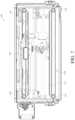
- FIG. 1is a perspective view of a skate sharpening system that is arranged and configured in accordance with certain features, aspects and advantages of the present disclosure
- FIG. 2is a front elevation view of the skate sharpening system of FIG. 1 ;
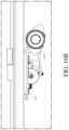
- FIG. 3is a right elevation view of the skate sharpening system of FIG. 1 ;
- FIG. 4is a rear elevation view of the skate sharpening system of FIG. 1 ;
- FIG. 5is a top view of the skate sharpening system of FIG. 1 ;
- FIG. 6is a left elevation view of the skate sharpening system of FIG. 1 ;
- FIG. 7is a bottom view of the skate sharpening system of FIG. 1 ;
- FIG. 8is a sectioned view of the skate sharpening system of FIG. 1 ;
- FIG. 9is an exploded view of a biasing arrangement of the skate sharpening system of FIG. 1 ;
- FIG. 10is a perspective view of a base of the skate sharpening system of FIG. 1 ;
- FIG. 11is a side view with the operative unit pivoted to a first open position relative to the base;
- FIG. 12is a side view with the operative unit pivoted to a second open position relative to the base;
- FIG. 13is a perspective view of the spindle assembly of the skate sharpening system of FIG. 1 ;
- FIG. 14is an exploded view of the spindle assembly of the skate sharpening system of FIG. 1 ;
- FIG. 15is a perspective view of the arbor shroud of the skate sharpening system of FIG. 1 ;
- FIGS. 16 A, 16 B, and 16 Care front views of skate sharpening system illustrating movement of the grinding wheel within the skate sharpening system of FIG. 1 ;
- FIG. 17is a perspective view of the spindle assembly and carriage assembly of the skate sharpening system of FIG. 1 ;
- FIG. 18illustrates a partial section view of the carriage assembly of the skate sharpening system of FIG. 1 ;
- FIG. 19illustrates an exploded view of components of the carriage assembly of the skate sharpening system of FIG. 1 .
- FIG. 1is a perspective view of a skate sharpening system 100 used to sharpen the blades of ice skates.
- the skate sharpening system 100is designed and configured to provide a safe, clean, and automated skate sharpening system.
- the skate sharpening system 100allows users to sharpen skates at home, on their own schedule, and with professional quality results. Operation of the skate sharpening system 100 generally can be as described in U.S. patent application Ser. No. 16/424,294, which was filed on May 28, 2019 and which published as U.S. Publ. No. 2020/0016716A1 on Jan. 16, 2020, which is hereby incorporated by reference. The following disclosure will touch upon certain improvements to the system disclosed in that published application.
- FIG. 1also shows a coordinate system for references to spatial directions within this disclosure.
- the X directionis left-to-right, the Y direction back-to-front, and the Z direction bottom-to-top with respect to the skate sharpener 10 in the upright, front-facing orientation of FIG. 1 .
- This coordinate systemalso defines an X-Y plane (horizontal), X-Z plane (vertical and left-to-right), and Y-Z plane (vertical and front-to-back).
- the illustrated skate sharpening system 100comprises an operative unit 102 and a base 104 .
- the illustrated operative unit 102contains blade retention assemblies for gripping an ice skate blade, grinding assemblies for sharpening the skate blade, and control arrangements for controlling the skate sharpener 100 .
- An ice skate bladecan by inserted into the skate slot 150 and secured by blade retention jaws 154 .
- Slot covers 152overly at least a portion of the skate slot 150 . The slot covers 152 can be moved along a portion of the length of the slot 150 to abut the ends of the skate blades that are secured by the blade retention jaws 154 .
- the base 104can have any suitable configuration and can be formed of any suitable material.
- the base 104is molded of a resin-based material.
- the base 104is formed from an optically translucent or an optically transparent material.
- the base 104can be formed from an optically clear material.
- Some desired materials from which the base 104 can be formedinclude, but are not limited to, polycarbonate, polystyrene, PET, or PETG.
- the base 104can comprise a plastic or metal structure and a clear or translucent window.
- the windowcan be positioned along any portion of the base.
- the windowcan be positioned on the front of the base such that the base 104 can provide structure and rigidity while maintaining a portion for viewing operation of the skate sharpening system.
- the base 104can be configured as a shallow bucket.
- the term “bucket”is intended to mean an open container or a container with an opening.
- the bucketforms a shallow enclosure or a shallow tray in the illustrated configuration.
- the bucketcan have one or more side wall and a bottom wall.
- the illustrated base 104is defined by a bucket that comprises a bottom wall 110 and four side walls.
- the bottom wall 110can be bounded by a right side wall 112 , a left side wall 114 , a front wall 116 , and a rear wall 118 .
- the bottom wall 110can include feet 120 .
- the bottom wall 110includes four feet 120 .
- the feet 120can be adjustable in some configurations to provide a small degree of leveling
- the illustrated feet 120are non-adjustable rubber feet.
- the non-adjustable rubber feet 120can be adhered within features that are integrally molded into the base 104 .
- the featuresare integrally molded into the bottom wall 110 in the illustrated configuration.
- the feetare protuberances that are integrally molded into the bottom wall 110 .
- the base 104is capable of flexing sufficiently to accommodate minor irregularities in any surface upon which the base is placed. For example, it has been found that the base 104 is capable of flexing a sufficient degree to accommodate an offset between any two feet 120 of up to 6 mm over a span of 19 cm.
- the illustrated base 104has a height H, a width W, and a depth D.
- the width Wexceeds the depth D and the height H.
- the width Wis large enough to underlie an adult or senior skate supported in the operative unit 102 for a sharpening operation.
- the height His less than the depth D.
- the height His just large enough to accommodate moving components of the operative unit 102 .
- the height His just enough to provide access to a grinding wheel 340 of the operative unit 102 and a filter assembly of the operative unit 102 .
- the heightis 103 mm
- the depthis 288 mm
- the widthis 630 mm.
- the base 104is configured to have a footprint of less than 2000 cm 2 .
- the widthis about twice the depth.
- the footprintis less than 2000 cm 2 with a width that is about twice the depth.
- a reflective surface 122can be provided on at least a portion of the bottom wall 110 of the base 104 .
- the reflective surface 122can be positioned under a path of the moving components of the operative unit 102 .
- the reflective surface 122can be positioned such that the reflective surface 122 can aid during an alignment process.
- the reflective surfaceis provided by a reflective sticker that is secured in position using adhesive.
- Other configurationscan be used keeping in mind a desire to have the reflective surface properly positioned after cleaning of the base 104 following a series of sharpening operations. In other words, the reflective surface desirably does not become dislodged as a result of routine operation of the device, including cleaning of the base 104 .
- At least one of the right side wall 112 and/or the left sidewall 114can carry a magnet 124 .
- the operative unit 102 and the base 104can be connected such that the operative unit 102 pivots relative to the base 104 .
- the magnet 124aligns with a sensor such that operation of the sharpening assembly of the operative unit 102 can be prevented unless the operative unit 102 is closed against the base 104 .
- the position of the operative unit 102 relative to the base 104can be indicated by the sensor depending upon the placement of the sensor relative to the magnet 124 .
- the magnet 124cooperates with a reed switch that tells the operative unit 102 whether the operative unit 102 is in an open position or a closed position.
- Other configurationsmay include the use of different switches or sensors to determine the position of the operative unit 102 relative to the base 104 .
- position detectioncan be performed by sensing means that include one or more of an optical switch, a mechanical switch, angle sensors, accelerometers, or other types of switches and sensors.
- the front wall 116can comprise at least one cut out 126 .
- the front wall 116includes a cut out 126 at each end of the front wall 116 .
- the cut-outs 126accommodate portions of the operative unit 102 .
- the cut-outs 126can have any suitable configuration. In the illustrated configuration, however, the cut-outs 126 closely align with corresponding surfaces of the operative unit 102 .
- the rear wall 118can include a vent feature 128 .
- the vent feature 128comprises a u-shaped opening.
- the vent feature 128can be sized and configure to accommodate the placement of an airflow outlet from the operative unit 102 .
- the vent feature 128aligns with the airflow outlet from the operative unit 102 when the operative unit 102 and the base 104 are connected together and when the operative unit 102 is in position for a sharpening operation.
- the illustrated vent featurecomprises a u-shaped or c-shaped recess that extends downward from an uppermost edge of the rear wall.
- the right side wall 112can include a right mount 130 and the left side wall 114 can include a left mount 132 .
- the mounts 130 , 132can be configured in any suitable manner keeping in mind a desire to support the operative unit 102 using the base 104 .
- the mounts 130 , 132define saddles.
- the saddleshave generally C-shaped ledges 134 , 136 with outer walls 138 , 140 .
- the ledges 134 , 136extend laterally outward from the right side wall 112 and the left side wall 114 of the base 104 .
- the ledges 134 , 136 in the illustrated configurationextend between the walls 138 , 140 and the walls 112 , 114 respectively.
- the operative unit 102includes assemblies for gripping an ice skate blade, for sharpening the skate blade, and for controlling the skate sharpener 100 .
- the illustrated operative unit 102generally comprises a central body 200 , a right end cap 202 and a left end cap 204 .
- the end caps 202 , 204can be secured to the central body 200 in any suitable manner. In the illustrated configuration, the end caps 202 , 204 are secured to the central body using threaded fasteners.
- the central body 200comprises a forward shelf 210 and a rear housing 212 .
- the forward shelf 210can be secured to the rear housing 212 in any suitable manner.
- the rear housing 212has a lip that overlies a rear portion of the forward shelf 210 and the forward shelf 210 and rear housing 212 are secured together with threaded fasteners from the bottom.
- the forward shelf 210is formed as an extrusion that can be cut to length in serial production.
- the rear housing 212is formed as an extrusion that can be cut to length in serial production.
- the end caps 202 , 204span the juncture between the forward shelf 210 and the rear housing 212 .
- the illustrated operative unit 102comprises a pair of biasing assemblies 220 , 222 .
- the illustrated biasing assemblies 220 , 222protrude outward from the end caps 202 , 204 .
- the biasing assemblies 220 , 222 and the mounts 130 , 132 of the base 104are sized and configured such that the biasing assemblies 220 , 222 can be received within and supported by the mounts 130 , 132 . At least a portion of the biasing assemblies 220 , 222 and the mounts 130 , 132 are secured against significant relative rotation.
- each of the mounts 130 , 132includes a respective pocket 224 , 226 .
- Each of the biasing assemblies 220 , 222incorporates a protuberance 230 , 232 .
- the protuberances 230 , 232are received within the respective pockets 224 , 226 .
- the interaction between the protuberances 230 , 232 and the pockets 224 , 226limits relative rotation between at least those portions.
- the protuberancescan be formed along the mounts and the biasing assemblies incorporate a pocket. Other configurations also can be used to limit the relative rotation between at least those portions.
- the biasing assemblies 220 , 222will be described with reference to the right biasing assembly 220 .
- the left biasing assembly 222is a mirror image of the right biasing assembly 220 and includes the same components.
- the illustrated biasing assembliesare mounted to the operative unit and locked to the base, it is possible to reverse this configuration such that the biasing assemblies are mounted to the base and locked to operative unit.
- the biasing assembliesexert a biasing force between the base and the operative unit.
- the biasing assembliesexert a pivotal biasing force in some configurations.
- the illustrated biasing assemblyincludes a cover 240 .
- the cover 240includes the protuberance 230 .
- the cover 240has a cup shape that accommodates a torsion spring 242 .
- the torsion spring 242includes a first leg 244 that is received within a hole 246 formed in the cover 240 .
- the torsion spring 242also includes a second leg 250 that is received within a hole 252 formed in the right end cap 202 .
- a hub 254extends outward from the right end cap 202 and the torsion spring 242 surrounds at least a portion of the hub 254 .
- the cover 240is secured to the right end cap 202 by a threaded fastener 256 (e.g., a thumbscrew) but the right end cap 202 is capable of pivoting movement relative to the cover 240 .
- a threaded fastener 256e.g., a thumbscrew
- a thumbscrew 256extends through an opening in the ledge 134 and engages with a threaded opening formed in the cover 240 .
- the cover 240does not pivot relative to the base 104 .
- the operative unit 102including the right end cap 202 , pivots relative to the cover 240 .
- the torsion spring 242unloads a biasing force as the operative unit 102 is pivoted into an opened position and the torsion spring 242 loads a biasing force as the operative unit 102 is pivoted into a closed position.
- the torsion spring 242helps to control a rate of descent of the operative unit 102 as the operative unit 102 moves between the open position and the closed position. In some configurations, the torsion spring 242 provides a sufficient biasing force to oppose final closure of the operative unit 102 against the base 104 without a force input by a user. In some configurations, the torsion spring 242 provides less resistive force such that the operative unit 102 will fully close against the base 104 without a force input by a user but the torsion spring 242 provides at least some opposition to the closure.
- a prop rodcan provide means for securing the operative unit 102 in an open position.
- the prop rodcan hold the operative unit 102 in one or more open orientations relative to the base 104 .
- the prop rodmay be in addition to the biasing assembly or the prop rod may be an alternative to the biasing assembly.
- the cover 240(or an analog for the cover 240 ) can be formed to have a hexagonal shape, for example but without limitation, while the corresponding mount 130 can have a complementary shape such that the operative unit 102 can be lifted from the base 104 , pivoted and then returned to the base at a different angle. In such a configuration, there is no need for the biasing assembly, for example. In such a configuration, the operative unit 102 may not be secured to the base 104 to oppose relative vertical movement between the operative unit 102 and the base 104 .
- pivot locationis near a center of gravity of the operative unit. If the pivot location was moved closer to the center of the side walls of the base 104 , then the bucket height would need to increase but lighter springs could be used. Such a configuration, however, may not be a desired tradeoff.
- the pivot locationcan intersect with the rear wall or a structure that extends from the rear wall.
- the illustrated pivot locationwas designed to facilitate a low profile for the base (and the overall system). As shown in FIG. 10 , there is a curvature along the sides of the base 104 .
- the operative unit 102has a complementary curved shape. These curves follow the center of rotation such that, when the operative unit 102 is in a closed position, a minimal amount of clearance exists between the base 104 and the operative unit 102 .
- Reduced clearance between the wallsreduces the likelihood of bypassed airflow, which allows increased airflow through the slot 150 that receives the skate (such that more of the swarf and dust can be pulled into the base 104 ).
- the systemoperates under vacuum; the fan pulls air into the base 104 and then exhausts that air through the back of the operative unit. The air is replaced primarily by air flowing in through the skate slot 150 . This flow of air will capture the swarf/dust from the grinding.
- sealscould be used to seal the gaps between the base 104 and the operative unit 102 , the variety of environments in which the system 100 may be used, such as those with a wide operating temperature swings, can make seal optimization difficult. Such seals also may increase friction and would increase costs.
- the operative unit 102 and the base 104are pivotally connected.
- the operative unit 102can be pivoted to an open position, such as shown in FIGS. 11 and 12 .
- the operative unit 102exceeds 15 pounds in weight in the illustrated configuration.
- a biasing assemblycan be used to assist with the raising and lowering of the operative unit 102 relative to the base 104 .
- means for securing the operative unit 102 in an open positioncan be provided.
- the means for securingcan include a prop rod that holds the operative unit 102 in a particular open orientation relative to the base 104 , a biasing assembly that supplies sufficient biasing force to maintain the operative unit 102 in an open orientation relative to the base 104 , or a mechanical locking configuration that provides physical stops to secure the operative unit 102 in one or more particular open orientations relative to the base 104 , for example but without limitation.
- a mechanical locking configuration 270is shown in FIG. 8 . While only the right side mechanical locking configuration 270 will be shown, a mirror image of the illustrated mechanical locking configuration 270 can be used on the left side. In some configurations, only one side has the locking configuration.
- the illustrated mechanical locking configuration 270comprises a trigger 272 .
- another suitable mechanismsuch as a button, latch, slide, switch, knob, pin, or other mechanism can be used to replace the trigger to actuate the mechanical locking configuration 270 .
- the trigger 272can include one or more grip locations 274 .
- the grip locations 274can be configured to receive one or more fingers of the user.
- a thumb pad 276can extend a short distance along a front of the system 100 . The short thumb pad 276 reduces any impact on visibility into the system 100 ; if an elongated thumb pad 276 extended a full length of the front of the operative unit 102 , the height of the overall system 100 may need to be increased to provide a desired level of access and vision. As shown in FIG.
- the thumb pad 276extends less than 1/10 of the full length of the operative unit 102 . In some configurations, the thumb pad extends to less than or equal to one half of the full length of the operative unit 102 . In some configurations, the thumb pad 276 is integrally formed with the end caps 202 , 204 . Such configurations advantageously facilitate forming the central body 200 of extrusions.
- the grip locations 274can guide a user to a desired placement of their hand while operating the mechanical locking configuration 270 .
- two mechanical locking configurations 270are provided such that both of the mechanical locking configurations 270 must be operated at the same time to pivot the operative unit 102 relative to the base 104 . Such configurations help to reduce pinching risks in an advantageous manner.
- a rod 280connects to the trigger 272 .
- the rod 280has a threaded end 282 that engages with threads of the trigger 272 .
- a circlip 284 and a spring 286provide a return force that opposes unlocking movement of the trigger. 272 .
- the spring 286is captured between an internal surface of the end cap 202 and the circlip 284 .
- Other configurationsare possible to provide the biasing force to the mechanical locking configuration 270 . In some less desired configurations, the biasing force is omitted.
- an engagement tip 290 of the rod 280extends beyond the end cap 202 to engage a recess 292 formed in the base 104 .
- the base 104can comprise one or more recess 292 that correlates to the one or more positions of the operative unit 102 relative to the base 104 that is desired to be maintained.
- the operative unit 102can be secured in any of three positions relative to the base 104 and, accordingly, three recesses 292 correlated to those positions.
- the first recess 292corresponds to a closed position
- the second recess 292corresponds to the position shown in FIG. 11
- the third recess 292corresponds to the position shown in FIG. 12 .
- the position in FIG. 11allows for access to the grinding wheel 340 and for adjustment of the position of the grinding wheel 340 .
- the position in FIG. 12allows for more complete access to the interior of the base 104 for cleaning and allows for improved access to a filter assembly for replacement of the filter.
- the biasing elements on the rod/trigger assemblycould be omitted and a pin or the rod could simply be inserted into the recess such that the operative unit can be pivoted and secured in a desired position (e.g., pin and overlapping hole assemblies).
- Other locking arrangementse.g., interference components, frictional components, adjustable friction components, adjustable interference components
- the operative unit 102may be configured to lock in position relative to the base 104 by tightening the end caps 202 , 204 and locking the unit at any height position. In other words, the end cap 202 could be tightened down by the user and, as the end cap 202 gets tighter, friction locks-out rotation of the operative unit 102 relative to the base 104 .
- FIGS. 13 and 14show an embodiment of the grinding wheel and spindle assembly 300 .
- the grinding wheel 340includes a metal grinding ring 344 disposed on a rigid hub 342 .
- the grinding wheel 340is mounted to an axle 336 of the spindle 302 by a retention nut 350 that urges the grinding wheel 340 against a metal arbor 330 that forms part of the spindle 302 .
- the grinding ring 344has an abrasive outer surface for removing material from a skate blade during a sharpening operation.
- both the arbor 330 and hub 342have shaped outer edges which mate with respective edges of the grinding ring 344 .
- the mating between the arbor 330 and grinding wheel 340is a sliding contact mating that permits mounting and dismounting of the grinding wheel 340 while also providing for heat transfer between the grinding ring 344 and the arbor 330 .
- the heat transferhelps dissipate frictional heat generated in the grinding ring 344 as it rotates against a skate blade in operation.
- this matingis between a portion of an inner annular surface of the grinding ring 344 and an annular outer rim 334 of the arbor 330 .
- Both the hub 342 and arbor 330have notches or shoulders on which respective portions of the grinding ring 344 rest.
- the shoulder portion of the hub 342extends only partway into the grinding ring 344 , so that a remaining part of the grinding ring 344 extends beyond the arbor-facing end of the hub 342 and mates with the shoulder portion of the arbor 330 .
- the arbor 330can include vanes 332 or other features to increase its surface area and/or enhance air flow for a desired cooling effect, further promoting heat dissipation and helping to maintain a desired operating temperature of the grinding ring 344 in operation.
- the vanes 332can provide a conductive and convective cooling effect.
- One challenge of the geometry and size of the grinding ring 344is heat removal, and this can be addressed in part by the heat-conducting mating with the arbor 330 and heat-dissipating features of the arbor 330 .
- the arbor shroud 310is further illustrated in FIG. 15 .
- the arbor shroud 310includes a body portion 312 , a sidewall 314 defining a shroud opening, a front wall 316 defining jaw protection features 328 , a lower opening 318 , fastener openings 320 , back wall 322 , and recessed walls 324 .
- the body portion 312extends distally from the front wall 316 .
- the body portion 312is configured to be mounted on the spindle 302 .
- the body portion 312comprises leg portions that extend distally from the front wall 316 and are configured to be secured to the spindle 302 .
- Each leg portionsextends circumferentially about a portion the spindle 302 .
- the body portion 312includes fastener openings 320 configured for attaching the shroud 310 to the spindle 302 using fasteners 308 .
- the legsare substantially symmetric with offset fastener openings 320 .
- the fastener openings 320are offset from each other in elevation to stabilize the shroud 310 when secured to the spindle 302 .
- the shroud 310is formed as a single molded part. In some embodiments, the shroud 310 may be formed from two or more separate pieces. The shroud 310 may be coupled to the spindle 302 using other means known in the art. Some desired materials from which the shroud 310 can be formed include, but are not limited to, Nylon, Glass-filled nylon, or POM.
- a gap 326is formed between the sidewall 314 and annular outer rim 334 and vanes 332 of the arbor 330 .
- the width of the side wall 314can cover at least a portion of the vanes 332 .
- the width of the side wall 314can be as wide as or greater than the width of the vanes 332 of the arbor 330 .
- the width of the front wall 316can be substantially the same as the width of the sidewall 314 .
- the width of the front wall 316 of the shroud 310is configured so that, when installed, it can fit between within the opening of the skate slot 150 with the grinding wheel 340 and arbor 330 (such as illustrated in FIG. 3 ).
- the configuration of the lower opening 318can help to effectively dissipate heat for cooling of the grinding wheel 340 during operation.
- the back wall 322can include one or more openings to provide additional airflow for heat dissipation.
- the sidewall 314can form an opening having a different shape, for example, the shroud opening may have a U-shape or other shaped opening. The gap between may not be uniform between the side wall and the arbor 330 .
- the shroud 310may be formed using a screen or fence-like construction. In such an embodiment, the screen can provide the same functionality of the walls of the shroud 310 . The screen can provide airflow through the arbor 330 , while also preventing access by the user with arbor 330 during operation of the skate sharpener.
- the shroud 310provides a protective cover over at least a portion of the arbor 330 .
- the shroud 310can cover at least a portion of the vanes 332 of the arbor 330 .
- the shroud 310may cover the width of the vanes 332 or may be wider and extend over a larger portion of the arbor 330 .
- the shroud 310can extend up to the thickness of the arbor 330 , to the extent that the shroud 310 does not interfere with the grinding operation.
- the grinding wheel 340 and arbor 330can be accessed from the topside of the sharpening unit and are sized to fit between with the walls of the skate slot 150 (such as illustrated in FIG. 5 ).
- the positioning of the shroud 310is configured to prevent human interaction with the arbor 330 , such as with the vanes 332 of the arbor 330 , during operation of the skate sharpener.
- the shroud 310helps to prevent accidental or intentional interaction with the arbor 330 during operation. Additionally, the shroud 310 can help to prevent sparks and swarf from escaping upwards during the sharpening operation and instead be captured by and within the base 104 .
- lobes 328With additional reference to FIGS. 16 A- 16 C , the functionality of lobes 328 is illustrated.
- the front wall 316forms lobes 328 on both sides of shroud 310 . If the sharpener were to operate without a skate between the jaws, the grinding wheel 340 could potentially grind a portion of the jaws.
- the lobes 328are configured to prevent the grinding wheel 340 from contacting components of the skate sharpener when it is operated without a skate blade inserted in the blade slot 150 and secured by blade retention jaws 154 .
- the lobes 328are configured to act as a ramp when the carriage moves laterally in the x direction during operation. When the lobes contact a lower surface of the jaws 154 ( FIG.
- the grinding wheel 340is displaced downward in the z direction ( FIG. 16 C ).
- the downward displacementprevents contact between the grinding wheel 340 and the jaws 154 .
- the lobesare disposed on both sides of the shroud 310 so that the ramp will function while the grinding wheel 340 is operating in either direction during the sharpening operation.
- the upper wall of the shroud 310may include a portion that is substantially flat, the flat portion is configured to slide along the lower surface of the jaws, as illustrated in FIG. 16 C .
- the jaw protection features 328are illustrated as triangular lobes on the shroud 310 .
- the jaw protection features 238may have a different shape or appearance.
- the jaw protection featureis included on a single side.
- FIGS. 17 - 19illustrate aspects of the grinding wheel alignment system. Specifically, the alignment system positions the grinding wheel 340 relative to the position of a skate blade inserted within blade slot 150 .
- the alignment systemprovides for the movement of the grinding ring along the y axis without backlash. Backlash is a common and undesired mechanical problem inherent in threaded or geared mechanisms.
- FIG. 17is a perspective view of the grinding wheel assembly 300 and carriage assembly 400 .
- FIG. 18illustrates a partial section view at the location of the alignment shaft 404 .
- FIG. 19illustrates an exploded view of components of the carriage assembly 400 .
- the alignment shaft 404is secured at each end to the carriage 402 . Shown on the left, the shaft 404 is secured in place by the end fastener 420 having screw threading corresponding to threading on an internal opening of the shaft 404 . The end fastener 420 secures an adjustment knob 418 , and bearing 414 in place on the left side of the carriage 402 . Shown on the right is a nut 416 having screw threading engaging corresponding screw threading on the alignment shaft 404 . Arranged between the nut 416 and the shaft is a bearing 412 .
- the alignment shaft 404includes a threaded portion 406 , a detents portion 408 , and an unthreaded portion 410 .
- the detents portion 408includes a plurality of detents disposed circumferentially about the shaft.
- the detents of the shaftextend along a longitudinal portion of the shaft between the threaded portion 406 and the unthreaded portion 410 .
- the detentsare sized and configured to engage the spring pin 436 .
- the spring pin 436has a fixed position and rides in the series of detents or recesses in the outer diameter of the shaft 404 . As the adjustment knob 418 is manipulated, each movement of the detents relative to the spring pin 436 corresponds to a single tactile and/or audible click of the adjustment wheel 418 .
- the spring pinmay be replaced by a ball and plunger or any spring-like feature that can provide audible and/or tactile feedback of the adjustment wheel 418 .
- detentscan be molded into the backside of knob 418 and a spring pin or ball plunger can be provided on the body of the carriage 402 .
- the detent mechanismcan be effectively implemented by using two surfaces in the assembly that rotate relative to each other when the adjustment knob 418 is manipulated. Each detent is sized and configured to correspond to a defined amount of movement of the grinding wheel 340 along the y-axis with each click of the adjustment wheel 418 .
- each clickcan correspond to of an adjustment between 0.005 and 0.04 of a mm of the y-position of the grinding wheel 340 .
- a clickis 1/26 th of a mm adjustment of the y-position of the grinding wheel 340 .
- the adjustment mechanismwill be further described below.
- the alignment shaft 404is further secured in place within the carriage 402 by the mounting bracket 426 .
- the mounting bracket 426includes compression brackets 428 .
- the mounting bracket 426is secured to the carriage by fasteners 434 .
- the mounting bracketincludes an axial path for the shaft 404 .
- the threaded bushing 424 and the through hole bushing 422are positioned within the axial path.
- the through hole bushing 422is positioned at least partially within the axial opening formed in compression bracket 428 A.
- the threaded bushing 424is positioned at least partially within the axial opening formed in compression bracket 428 B.
- the threaded portion 406 of the shaft 404includes threading that corresponds to threading of the threaded bushing 424 .
- the through hole bushing 422can have a reamed diameter that is substantially the same as the diameter of the unthreaded portion 410 of the shaft 404 . Reaming the through hole bushing can result in a more accurate fit.
- the through hole bushing 422can be configured to have an interference fit with the unthreaded portion of the shaft 404 . In some embodiments, only a single bushing may be used.
- the bushingmay be a threaded bushing or a through hole bushing.
- the bushings 422 , 424can include tabs 440 that are configured to longitudinally space the bushings along the axial path and prevent the bushings from rotating during operation.
- the shaft 404is positioned within the axial path of the mounting bracket 426 .
- the threaded bushing 424is threaded onto the threaded portion 406 of the shaft 404 and positioned within the axial opening of compression bracket 428 B.
- the through hole bushing 422is positioned on the unthreaded portion 410 of the shaft 404 and positioned within the axial opening of compression bracket 428 A.
- the through hole bushing 422is a follower.
- the bushings 422 , 424can be formed from any suitable material but a polymer is used in this embodiment. Some desired polymers from which the bushings 422 , 424 can be formed include, but are not limited to, POM (acetal), UHMW polyethylene, or Nylon.
- the spacing bracket 432is positioned between bushings 422 and 424 . With respect to the shaft 404 , the spacing bracket 432 is configured to be positioned over the detent portion 408 .
- the spacing bracket 432includes a recess 438 sized and configured to receive the spring pin 436 . As described above, the spring pin 436 is configured to engage the detents in the shaft 404 .
- the longitudinal positions of the bushings 422 , 424are secured between the spacing bracket 432 and compression brackets 428 A-B by tabs 440 .
- the compression brackets 428 A-Bare configured to tighten and secure the position of the shaft 404 relative to the bushings 422 , 424 When the compression brackets are secured, they cause the bushings 422 , 424 to contract on the corresponding portion of the shaft 404 and secure the shaft in place. Tabs 440 on the bushings 422 , 424 prevent the bushings from rotating during operation. The bushings 422 , 424 apply a force on the shaft that is sufficient to prevent undesired rotation of the shaft 404 , such as during a sharpening operation. However, the lubricity of the polymer material of the bushings allows the shaft 404 to rotate without binding when the adjustment knob 418 is manipulated.
- the compression of the bushings on the shaft 404additionally secures the position of the shaft such that there is substantially no hysteresis, backlash, or uncertainty of location caused by rotation of the adjustment knob 418 .
- the shaft 404can rotate from forward to backward and visa-versa without backlash when the adjustment knob 418 is manipulated, regardless of the y-position of the grinding wheel 340 .
- By compressing the polymer bushingsany undesired rotation is prevented. Additionally, any desired rotation is not inhibited.
- the adjustment knob 418can be manipulated by a user in order to adjust the rotation of the shaft 404 .
- the adjustment knobmay be configured to be manipulated by an electronically controlled alignment system.
- the shaftmay be rotated by a motor, such as a stepper or servo motor.
- the systemmay utilize a machine vision system or encoder to determine alignment.
- the componentscan be controlled by a controller.
- the grinding ringis adjustable in the transverse or Y-direction.
- the motor armpivots on bearing 412 and bearing 414 .
- the systemcan use bushings in place of bearings.
- the threaded shaft 404moves the assembly in and out in the Y-direction.
- the Y-position of the grinding wheel assembly 300is varied by user rotation of the adjustment knob 418 .
- the detents 408 and spring pin 436are co-configured to form a detent mechanism providing several detent locations for a rotation of the adjustment knob during the adjustment process.
- Each click of the adjustment knobprovides for alignment of the grinding wheel assembly 300 by a defined adjustment amount (e.g., 1/26 th of a mm per click) of the grinding wheel 340 position in the y direction.
- the screw actioncauses the carriage assembly 400 to move transversely in the Y direction along the alignment shaft 404 , and move the grinding wheel assembly 300 transversely along with it.
- the alignment systemis configured to reduce or eliminate undesired transverse movement of the grinding wheel assembly 300 during an alignment operation. Additionally, the alignment system prevents undesirable transverse movement resulting from a sharpening operation.
- the detent systemcan also help to prevent undesirable movement and facilitate desirable movement. As the adjustment knob 418 is rotated, the shaft 404 is rotated and the spring pin 436 moves from one detent to the next, requiring a small force to push the spring pin 436 sufficiently out of the first detent and into the next.
- the configuration of the alignment shaft 404 and bushings 422 , 424prevent undesirable movement during alignment or operation.
- the compression of the bushings 422 , 424 on the shaft 404increases the force required to rotate the shaft. This has the effect of fixing the position of the shaft such that there is no movement or play in the rotation of the adjustment knob 418 .
- the force to move the shaft 404 through the detent positionsis easily generated by the rotation of the adjustment knob 418 .
- vibration or other mechanical forces occurring during sharpening operationdo not have the force to cause the rotation of the shaft between detent position.
- each embodiment of this disclosuremay comprise, additional to its essential features described herein, one or more features as described herein from each other embodiment disclosed herein.
- the terms “generally parallel” and “substantially parallel”refer to a value, amount, or characteristic that departs from exactly parallel by less than or equal to 15 degrees, 10 degrees, 5 degrees, 3 degrees, 1 degree, 0.1 degree, or otherwise.
- the inventionmay also be said broadly to consist in the parts, elements and features referred to or indicated in the description of the application, individually or collectively, in any or all combinations of two or more of said parts, elements or features.
Landscapes
- Engineering & Computer Science (AREA)
- Mechanical Engineering (AREA)
- Finish Polishing, Edge Sharpening, And Grinding By Specific Grinding Devices (AREA)
- Footwear And Its Accessory, Manufacturing Method And Apparatuses (AREA)
Abstract
Description
Claims (20)
Priority Applications (1)
| Application Number | Priority Date | Filing Date | Title |
|---|---|---|---|
| US18/649,552US12337436B2 (en) | 2020-07-31 | 2024-04-29 | Skate blade sharpening system |
Applications Claiming Priority (3)
| Application Number | Priority Date | Filing Date | Title |
|---|---|---|---|
| US202063059885P | 2020-07-31 | 2020-07-31 | |
| US16/989,770US11969851B2 (en) | 2020-07-31 | 2020-08-10 | Skate blade sharpening system |
| US18/649,552US12337436B2 (en) | 2020-07-31 | 2024-04-29 | Skate blade sharpening system |
Related Parent Applications (1)
| Application Number | Title | Priority Date | Filing Date |
|---|---|---|---|
| US16/989,770ContinuationUS11969851B2 (en) | 2020-07-31 | 2020-08-10 | Skate blade sharpening system |
Publications (2)
| Publication Number | Publication Date |
|---|---|
| US20250025975A1 US20250025975A1 (en) | 2025-01-23 |
| US12337436B2true US12337436B2 (en) | 2025-06-24 |
Family
ID=80004015
Family Applications (2)
| Application Number | Title | Priority Date | Filing Date |
|---|---|---|---|
| US16/989,770Active2042-12-10US11969851B2 (en) | 2020-07-31 | 2020-08-10 | Skate blade sharpening system |
| US18/649,552ActiveUS12337436B2 (en) | 2020-07-31 | 2024-04-29 | Skate blade sharpening system |
Family Applications Before (1)
| Application Number | Title | Priority Date | Filing Date |
|---|---|---|---|
| US16/989,770Active2042-12-10US11969851B2 (en) | 2020-07-31 | 2020-08-10 | Skate blade sharpening system |
Country Status (4)
| Country | Link |
|---|---|
| US (2) | US11969851B2 (en) |
| EP (1) | EP4188563B1 (en) |
| CA (1) | CA3190442A1 (en) |
| WO (1) | WO2022026976A1 (en) |
Families Citing this family (1)
| Publication number | Priority date | Publication date | Assignee | Title |
|---|---|---|---|---|
| US10300574B2 (en) | 2014-10-24 | 2019-05-28 | Velasa Sports, Inc. | Skate blade sharpening system |
Citations (140)
| Publication number | Priority date | Publication date | Assignee | Title |
|---|---|---|---|---|
| US1219004A (en) | 1915-08-16 | 1917-03-13 | Harry E Kalanquin | Skate-clamp. |
| US1381724A (en)* | 1920-05-18 | 1921-06-14 | James A Maloney | Safety-razor and strop |
| US2114967A (en) | 1936-09-19 | 1938-04-19 | American Floor Surfacing Mach | Surfacing machine |
| US2438543A (en) | 1945-01-08 | 1948-03-30 | Jack Shaw | Abrading machine |
| US2563018A (en) | 1947-01-15 | 1951-08-07 | Fello Joseph | Ice skate grinding machine |
| US2599952A (en) | 1951-06-04 | 1952-06-10 | Strayer Wilfred | Grinding wheel blower |
| US2722792A (en) | 1953-06-22 | 1955-11-08 | Continental Machines | Water cooled grinding wheel |
| US2775075A (en) | 1949-02-16 | 1956-12-25 | G M Lab Inc | Knife sharpener |
| US2819568A (en) | 1957-04-18 | 1958-01-14 | John N Kasick | Grinding wheel |
| US2990661A (en) | 1958-07-10 | 1961-07-04 | Donald P Hackett | Backing disk for abrasive sheet |
| US3118256A (en) | 1964-01-21 | de witt | ||
| US3259959A (en) | 1963-10-23 | 1966-07-12 | Alton E Tobey | Air cooled rasp |
| US3524285A (en) | 1966-08-09 | 1970-08-18 | Carborundum Co | Control system for grinding machines |
| US3574975A (en) | 1967-11-13 | 1971-04-13 | Erich P Liss | Dry grinding warp preventer |
| US3650073A (en) | 1970-02-16 | 1972-03-21 | Charles Weisman | Iceskate blade sharpening machine and method of using said machine for sharpening iceskate blades |
| US3735533A (en) | 1971-02-12 | 1973-05-29 | Merco Int Ltd | Sharpening of ice skates |
| US3742655A (en) | 1972-01-14 | 1973-07-03 | Oliver Inc L | Abrading wheel |
| US3756796A (en) | 1967-12-13 | 1973-09-04 | Super Cut | Method of forming a peripheral grinding wheel |
| US3789551A (en) | 1972-02-28 | 1974-02-05 | Custom Radius Corp | Skate sharpening devices |
| US3800632A (en) | 1970-05-01 | 1974-04-02 | J Juranitch | Blade sharpening guide |
| US3827185A (en) | 1971-07-29 | 1974-08-06 | Match E Co Ltd | Ice skate sharpening apparatus |
| US3839828A (en) | 1973-02-21 | 1974-10-08 | R Arnold | Method and apparatus for sharpening skates |
| US3881280A (en)* | 1974-10-29 | 1975-05-06 | Arnold M Thompson | Ice skate sharpening device with a floating skate guiding member |
| US3948001A (en) | 1973-10-05 | 1976-04-06 | Agency Of Industrial Science & Technology | Curved surface grinding machine |
| US3956857A (en) | 1973-04-20 | 1976-05-18 | Charles Weisman | Ice skate blade sharpening machine |
| US3988124A (en) | 1975-06-26 | 1976-10-26 | Babcock Roger M | Skate sharpening machine |
| US3988865A (en) | 1973-03-02 | 1976-11-02 | Charles Weisman | Clamp and jig for use therewith |
| US4055026A (en) | 1974-12-30 | 1977-10-25 | Zwicker Homer A | Clamp for holding ice skate while grinding blade |
| US4078337A (en) | 1977-01-10 | 1978-03-14 | Chiasson Robert H | Apparatus for sharpening ice skate blades and the like |
| US4094101A (en) | 1976-04-01 | 1978-06-13 | Bertrand Robinson | Ice-skate sharpener |
| US4109419A (en) | 1977-01-12 | 1978-08-29 | Sidney Broadbent | Ice skate sharpening devices |
| US4172343A (en) | 1976-11-26 | 1979-10-30 | Glenn Sakcriska | Ice skate sharpener |
| US4235050A (en)* | 1978-07-13 | 1980-11-25 | Universal Skate Sharpener Ltd. | Skate sharpening apparatus |
| US4235052A (en) | 1979-01-08 | 1980-11-25 | Guidry Joseph L | Fan disc |
| US4271635A (en) | 1978-11-29 | 1981-06-09 | Szalay John J | Ice skate-sharpening apparatus |
| US4294043A (en) | 1978-01-16 | 1981-10-13 | Glenn Sakcriska | Ice skate sharpener |
| US4516357A (en) | 1983-02-15 | 1985-05-14 | Paul Gach | Coolant supply apparatus for a grinding tool |
| US4534134A (en) | 1983-06-10 | 1985-08-13 | Universal Skate Sharpeners Ltd. | Ice skate sharpening machine |
| US4549372A (en) | 1980-04-02 | 1985-10-29 | De Beers Industrial Diamond Division (Proprietary) Limited | Grinding wheel |
| US4558541A (en) | 1983-06-10 | 1985-12-17 | Universal Skate Sharpeners Ltd. | Ice skate sharpening method |
| US4570387A (en) | 1983-05-27 | 1986-02-18 | Toyoda Koki Kabushiki Kaisha | Centerless grinding machine |
| EP0175168A2 (en) | 1984-09-03 | 1986-03-26 | Robert Ek | Method and apparatus for grinding the slide surface of skates |
| US4615149A (en) | 1984-05-23 | 1986-10-07 | Toyoda Koki Kabushiki Kaisha | Feed control apparatus for grinding machine |
| US4615144A (en) | 1984-08-09 | 1986-10-07 | Peacock Wally E | Portable skate sharpener |
| CA1229985A (en) | 1984-07-16 | 1987-12-08 | Norman Paquette | Skate clamp |
| US4756125A (en) | 1987-02-02 | 1988-07-12 | Kadnar Frank W | Skate blade sharpening device |
| US4967515A (en) | 1988-07-28 | 1990-11-06 | Toyoda Koki Kabushiki Kaisha | Numerically controlled grinding machine |
| US5009039A (en) | 1987-07-17 | 1991-04-23 | Svenska Skatebox Ab | Skate sharpening device |
| US5127194A (en) | 1990-08-10 | 1992-07-07 | Jobin Jeane Pierre | Apparatus for sharpening the blade of a skate |
| US5129190A (en) | 1990-10-31 | 1992-07-14 | Eaton Corporation | Machining and apparatus |
| USD328305S (en) | 1989-10-09 | 1992-07-28 | Wong Alex Y K | Air compressor |
| US5139138A (en)* | 1989-10-16 | 1992-08-18 | Isaksen Olaf L | Combination razor and container with sharpener |
| US5172680A (en)* | 1991-10-11 | 1992-12-22 | Equipment Development Co., Inc. | Dust removal kit for masonry table-saw |
| US5177901A (en) | 1988-11-15 | 1993-01-12 | Smith Roderick L | Predictive high wheel speed grinding system |
| US5189845A (en) | 1990-06-14 | 1993-03-02 | Courchesne Richard L | Blade sharpening device and method |
| US5259148A (en) | 1991-11-12 | 1993-11-09 | Wiand Ronald C | Ring generator wheel with improved coolant flow |
| US5547416A (en) | 1994-08-26 | 1996-08-20 | Timms; Alfred R. | Skate sharpening gauge |
| US5562526A (en) | 1993-03-29 | 1996-10-08 | Toyoda Koki Kabushiki Kaisha | Method and apparatus for grinding a workpiece |
| US5591069A (en)* | 1994-11-14 | 1997-01-07 | Wurthman; Michael H. | Portable blade sharpener for ice skates |
| US5601473A (en) | 1993-12-03 | 1997-02-11 | M.J.S. Manufacturing, Inc. | Skate sharpening apparatus and method |
| US5823854A (en) | 1996-05-28 | 1998-10-20 | Industrial Technology Research Institute | Chemical-mechanical polish (CMP) pad conditioner |
| US5897428A (en) | 1997-02-04 | 1999-04-27 | Sakcriska; Glenn | Device for contouring and sharpening ice skate blades |
| US5924915A (en) | 1997-08-18 | 1999-07-20 | Wachtler; William R. | Hand held self aligning shaft grinder |
| CA2260531A1 (en) | 1998-02-27 | 1999-08-27 | George J. Balastik | Device for bringing object to be sharpened into contact with grinding wheel |
| US5989114A (en) | 1997-10-21 | 1999-11-23 | Unova Ip Corp. | Composite grinding and buffing disc with flexible rim |
| US6116989A (en) | 1998-01-16 | 2000-09-12 | Balastik; George Jiri | Apparatus for dressing a grinding disc |
| CA2309222A1 (en) | 1999-05-21 | 2000-11-21 | Wolfgang Blach | Skate sharpener |
| US20020009964A1 (en) | 2000-07-22 | 2002-01-24 | Deere & Company, Delaware Corporation | Grinding arrangement |
| CA2323321A1 (en) | 2000-10-17 | 2002-04-17 | Guspro Inc. | Dressing apparatus for grinding wheels |
| US6602109B1 (en) | 1998-12-16 | 2003-08-05 | University Of Massachusetts | Grinding wheel system |
| US20030156401A1 (en) | 2002-02-21 | 2003-08-21 | Big Daishowa Seiki Co., Ltd. | Information-holding unit |
| USD478905S1 (en) | 2002-07-31 | 2003-08-26 | Cross Match Technologies, Inc. | Fingerprint scanner |
| US6626745B1 (en) | 1996-07-05 | 2003-09-30 | Darex Corporation | Precision drill sharpener and grinding wheel assembly therefor |
| US20040209547A1 (en) | 2003-04-16 | 2004-10-21 | Kabushiki Kaisha Topcon | Method for processing chamfering of eyeglass lens and apparatus for processing the same |
| US20050130571A1 (en) | 2003-12-16 | 2005-06-16 | August Sunnen | Self-centering skate holder |
| EP1604782A1 (en) | 2004-06-08 | 2005-12-14 | Fraunhofer-Gesellschaft zur Förderung der angewandten Forschung e.V. | Grinding tool with integrated micromagnetic sensors |
| US20060040587A1 (en) | 2004-08-20 | 2006-02-23 | Magnus Eriksson | Automatic sharpening system for ice-skates |
| US7018280B2 (en) | 2004-06-07 | 2006-03-28 | Black & Decker Inc. | Sanding apparatus |
| US20060159533A1 (en) | 2004-12-17 | 2006-07-20 | Zeiler Jeffrey M | Smart accessories for power tools |
| USD525936S1 (en) | 2003-10-24 | 2006-08-01 | Smc Kabushiki Kaisha | Signal input device |
| US20060183411A1 (en)* | 2005-02-16 | 2006-08-17 | Robert Moon | Portable skate sharpener |
| USD527225S1 (en) | 2005-04-28 | 2006-08-29 | Vector Products, Inc. | Combined rechargeable travel cooler and warmer |
| US7104876B1 (en) | 2005-06-21 | 2006-09-12 | Kun-Meng Lin | Cutter-grinder |
| US20060223419A1 (en) | 2005-04-04 | 2006-10-05 | Robert Moon | Height comparator |
| US7118466B2 (en) | 2004-11-22 | 2006-10-10 | Laney W L | Scissor sharpening machine |
| US7121932B2 (en) | 2004-07-06 | 2006-10-17 | Ming-Ko Liao | Portable drill sharpener |
| US20070054598A1 (en) | 2003-10-22 | 2007-03-08 | Nippei Toyama Corporation | Locking mechanism of linear motor travel slider and processing machine |
| US20070184756A1 (en) | 2006-02-08 | 2007-08-09 | Dieck James H | Rotary Mower Blade Sharpener Having Movable Griding Wheels |
| US20070251677A1 (en)* | 2006-04-26 | 2007-11-01 | Foxconn Technology Co., Ltd. | Heat dissipation apparatus with guilding plates for guiding airflow flowing through a fin assembly |
| US20080004743A1 (en) | 2006-06-28 | 2008-01-03 | 3M Innovative Properties Company | Abrasive Articles, CMP Monitoring System and Method |
| US7387562B1 (en) | 2007-04-04 | 2008-06-17 | Gary Joseph Blum | Blade sharpening device |
| US20080176496A1 (en) | 2007-01-24 | 2008-07-24 | Hung-Nung Tasi | Knife Sharpener |
| US20080280548A1 (en) | 2007-05-10 | 2008-11-13 | Murray David Wilson | Ice skate blade sharpening machine |
| WO2009076496A2 (en) | 2007-12-11 | 2009-06-18 | Kennametal Inc. | Cutting tool with integrated circuit chip |
| USD594952S1 (en) | 2008-04-21 | 2009-06-23 | Smc Corporation | Control unit for ionizer |
| USD595318S1 (en) | 2007-10-12 | 2009-06-30 | Tecomec S.P.A. | Bench chain grinder |
| USD603432S1 (en) | 2008-05-02 | 2009-11-03 | 1339513 Ontario Ltd. | Ice skate holder |
| US20100068975A1 (en)* | 2008-03-12 | 2010-03-18 | Menachem Yadid | Razor blade sharpener and method of sharpening |
| US20100125362A1 (en) | 2008-11-20 | 2010-05-20 | Disney Enterprises, Inc. | Self-service beverage and snack dispensing using identity-based access control |
| US20110169233A1 (en) | 2007-05-10 | 2011-07-14 | 1339513 Ontario Ltd. | Ice skate blades and sharpening machines |
| US20110201257A1 (en) | 2010-02-15 | 2011-08-18 | Walker Shane R | Adjustable knife sharpener |
| US20120108151A1 (en) | 2010-11-02 | 2012-05-03 | Jason Swist | Multiple Blade Sharpening Apparatus and Method |
| US8197304B2 (en) | 2007-09-27 | 2012-06-12 | Woodpeckers, Inc. | Method and apparatus for sharpening a tool blade |
| US20120190279A1 (en) | 2011-01-24 | 2012-07-26 | Giovanni Ficai | Ventilating insert for abrasive tools |
| USD665830S1 (en) | 2011-03-28 | 2012-08-21 | 1339513 Ontario Ltd. | Multiple spinner carousel for dressing a grinding wheel |
| US8246425B2 (en) | 2010-01-15 | 2012-08-21 | J. Walter Company Ltd. | Abrasive wheel comprising a fan-like structure |
| US20120302147A1 (en) | 2011-05-26 | 2012-11-29 | Black And Decker Inc. | Airfolw arrangement for a power tool |
| US8430723B2 (en) | 2009-04-23 | 2013-04-30 | Guspro Inc. | Contour guide for ice skate sharpener |
| USD682646S1 (en) | 2010-09-29 | 2013-05-21 | Bolttech, Inc. | Control unit |
| US20130344774A1 (en) | 2012-06-22 | 2013-12-26 | Robert H. Allen | Stake sharpening holder, skate blade, and method of use |
| US20140087639A1 (en)* | 2012-03-06 | 2014-03-27 | Born Sharp, Llc | Razor sharpening system |
| US8696407B2 (en) | 2007-12-21 | 2014-04-15 | Darex, Llc | Cutting tool sharpener |
| US20140179201A1 (en) | 2012-12-21 | 2014-06-26 | Aiguisage Elite Inc. | Blade sharpening system and method of using the same |
| USD708922S1 (en) | 2010-05-21 | 2014-07-15 | Gervase Lionel Thorngate Evans | Tool sharpening apparatus for chisel and plane blades |
| US20140213160A1 (en) | 2013-01-30 | 2014-07-31 | James Herbert Page | Apparatus for sharpening blades |
| US8888567B2 (en) | 2011-06-09 | 2014-11-18 | Robert H. Allen | Skate sharpening squaring device and method of use |
| US20150061204A1 (en) | 2013-09-05 | 2015-03-05 | Daniel R. Talbot | Vise for skateboard |
| USD725453S1 (en) | 2013-02-28 | 2015-03-31 | American Learning Systems, Inc. | Blade sharpener housing |
| US20150140901A1 (en) | 2013-11-19 | 2015-05-21 | Eriksson Teknik Ab | Method for automatic sharpening of a blade |
| US9114498B1 (en) | 2014-10-24 | 2015-08-25 | Velasa Sports, Inc. | Skate blade sharpening system with protective covers |
| US20150367224A1 (en) | 2014-06-20 | 2015-12-24 | Magna Closures Inc. | Skate sharpening fixture |
| US9242330B1 (en)* | 2014-10-24 | 2016-01-26 | Velasa Sports, Inc. | Skate blade sharpening system with alignment visualization and adjustment |
| WO2016065237A2 (en) | 2014-10-24 | 2016-04-28 | Velasa Sports, Inc. | Skate blade sharpening system |
| US20160114454A1 (en)* | 2014-10-24 | 2016-04-28 | Velasa Sports, Inc. | Grinding wheel with identification tag |
| US9339911B2 (en) | 2013-11-19 | 2016-05-17 | Eriksson Teknik Ab | Method for automatic sharpening of a blade |
| US9352437B2 (en)* | 2014-10-24 | 2016-05-31 | Velasa Sports, Inc. | Skate blade retention mechanism with jaw guides |
| USD757514S1 (en) | 2014-10-21 | 2016-05-31 | Tecomec S.R.L. | Chainsaw sharpener |
| US9475175B2 (en)* | 2014-10-24 | 2016-10-25 | Velasa Sports, Inc. | Grinding wheel arbor |
| WO2016183663A1 (en) | 2015-05-19 | 2016-11-24 | Skatescribe Corporation | Methods of measuring and grinding an ice blade, and apparatuses using same |
| USD772670S1 (en) | 2015-03-20 | 2016-11-29 | Cembre S.P.A. | Tool |
| US9566682B2 (en)* | 2014-10-24 | 2017-02-14 | Velasa Sports, Inc. | Skate blade retention mechanism |
| US9573236B2 (en)* | 2015-05-28 | 2017-02-21 | Velasa Sports, Inc. | Skate blade sharpening system with alignment adjustment using alignment wheel |
| US20170165808A1 (en)* | 2015-12-15 | 2017-06-15 | John P. Buser | Adaptive Dust Shield Device Having Zero Standoff Capability |
| USD793830S1 (en) | 2015-07-08 | 2017-08-08 | Velasa Sports, Inc. | Skate blade sharpening system |
| US20170355056A1 (en)* | 2014-10-24 | 2017-12-14 | Velasa Sports, Inc. | Skate blade sharpening system |
| US9902035B2 (en)* | 2014-10-24 | 2018-02-27 | Velasa Sports, Inc. | Compact grinding wheel |
| US20180126250A1 (en)* | 2015-04-27 | 2018-05-10 | Aiguisage Elite Inc. | Blade sharpening system and method of using the same |
| US10335925B2 (en) | 2016-03-03 | 2019-07-02 | Velasa Sports, Inc. | Skate blade holder tool |
| US20200376621A1 (en) | 2019-05-29 | 2020-12-03 | Darex, Llc | Powered sharpener with manual hone stage |
| US20210069853A1 (en) | 2019-09-11 | 2021-03-11 | Eriksson Teknik Ab | Automatic blade holder |
- 2020
- 2020-08-10USUS16/989,770patent/US11969851B2/enactiveActive
- 2021
- 2021-06-30WOPCT/US2021/070805patent/WO2022026976A1/ennot_activeCeased
- 2021-06-30EPEP21745670.6Apatent/EP4188563B1/enactiveActive
- 2021-06-30CACA3190442Apatent/CA3190442A1/enactivePending
- 2024
- 2024-04-29USUS18/649,552patent/US12337436B2/enactiveActive
Patent Citations (157)
| Publication number | Priority date | Publication date | Assignee | Title |
|---|---|---|---|---|
| US3118256A (en) | 1964-01-21 | de witt | ||
| US1219004A (en) | 1915-08-16 | 1917-03-13 | Harry E Kalanquin | Skate-clamp. |
| US1381724A (en)* | 1920-05-18 | 1921-06-14 | James A Maloney | Safety-razor and strop |
| US2114967A (en) | 1936-09-19 | 1938-04-19 | American Floor Surfacing Mach | Surfacing machine |
| US2438543A (en) | 1945-01-08 | 1948-03-30 | Jack Shaw | Abrading machine |
| US2563018A (en) | 1947-01-15 | 1951-08-07 | Fello Joseph | Ice skate grinding machine |
| US2775075A (en) | 1949-02-16 | 1956-12-25 | G M Lab Inc | Knife sharpener |
| US2599952A (en) | 1951-06-04 | 1952-06-10 | Strayer Wilfred | Grinding wheel blower |
| US2722792A (en) | 1953-06-22 | 1955-11-08 | Continental Machines | Water cooled grinding wheel |
| US2819568A (en) | 1957-04-18 | 1958-01-14 | John N Kasick | Grinding wheel |
| US2990661A (en) | 1958-07-10 | 1961-07-04 | Donald P Hackett | Backing disk for abrasive sheet |
| US3259959A (en) | 1963-10-23 | 1966-07-12 | Alton E Tobey | Air cooled rasp |
| US3524285A (en) | 1966-08-09 | 1970-08-18 | Carborundum Co | Control system for grinding machines |
| US3574975A (en) | 1967-11-13 | 1971-04-13 | Erich P Liss | Dry grinding warp preventer |
| US3756796A (en) | 1967-12-13 | 1973-09-04 | Super Cut | Method of forming a peripheral grinding wheel |
| US3650073A (en) | 1970-02-16 | 1972-03-21 | Charles Weisman | Iceskate blade sharpening machine and method of using said machine for sharpening iceskate blades |
| US3800632A (en) | 1970-05-01 | 1974-04-02 | J Juranitch | Blade sharpening guide |
| US3735533A (en) | 1971-02-12 | 1973-05-29 | Merco Int Ltd | Sharpening of ice skates |
| US3827185A (en) | 1971-07-29 | 1974-08-06 | Match E Co Ltd | Ice skate sharpening apparatus |
| US3742655A (en) | 1972-01-14 | 1973-07-03 | Oliver Inc L | Abrading wheel |
| US3789551A (en) | 1972-02-28 | 1974-02-05 | Custom Radius Corp | Skate sharpening devices |
| US3839828A (en) | 1973-02-21 | 1974-10-08 | R Arnold | Method and apparatus for sharpening skates |
| US3988865A (en) | 1973-03-02 | 1976-11-02 | Charles Weisman | Clamp and jig for use therewith |
| US3956857A (en) | 1973-04-20 | 1976-05-18 | Charles Weisman | Ice skate blade sharpening machine |
| US3948001A (en) | 1973-10-05 | 1976-04-06 | Agency Of Industrial Science & Technology | Curved surface grinding machine |
| US3881280A (en)* | 1974-10-29 | 1975-05-06 | Arnold M Thompson | Ice skate sharpening device with a floating skate guiding member |
| US4055026A (en) | 1974-12-30 | 1977-10-25 | Zwicker Homer A | Clamp for holding ice skate while grinding blade |
| US3988124A (en) | 1975-06-26 | 1976-10-26 | Babcock Roger M | Skate sharpening machine |
| US4094101A (en) | 1976-04-01 | 1978-06-13 | Bertrand Robinson | Ice-skate sharpener |
| US4172343A (en) | 1976-11-26 | 1979-10-30 | Glenn Sakcriska | Ice skate sharpener |
| US4078337A (en) | 1977-01-10 | 1978-03-14 | Chiasson Robert H | Apparatus for sharpening ice skate blades and the like |
| US4109419A (en) | 1977-01-12 | 1978-08-29 | Sidney Broadbent | Ice skate sharpening devices |
| US4294043A (en) | 1978-01-16 | 1981-10-13 | Glenn Sakcriska | Ice skate sharpener |
| US4235050A (en)* | 1978-07-13 | 1980-11-25 | Universal Skate Sharpener Ltd. | Skate sharpening apparatus |
| CA1118514A (en) | 1978-07-13 | 1982-02-16 | James H. Hannaford | Skate sharpening apparatus |
| US4271635A (en) | 1978-11-29 | 1981-06-09 | Szalay John J | Ice skate-sharpening apparatus |
| US4235052A (en) | 1979-01-08 | 1980-11-25 | Guidry Joseph L | Fan disc |
| US4549372A (en) | 1980-04-02 | 1985-10-29 | De Beers Industrial Diamond Division (Proprietary) Limited | Grinding wheel |
| US4516357A (en) | 1983-02-15 | 1985-05-14 | Paul Gach | Coolant supply apparatus for a grinding tool |
| US4570387A (en) | 1983-05-27 | 1986-02-18 | Toyoda Koki Kabushiki Kaisha | Centerless grinding machine |
| US4558541A (en) | 1983-06-10 | 1985-12-17 | Universal Skate Sharpeners Ltd. | Ice skate sharpening method |
| US4534134A (en) | 1983-06-10 | 1985-08-13 | Universal Skate Sharpeners Ltd. | Ice skate sharpening machine |
| US4615149A (en) | 1984-05-23 | 1986-10-07 | Toyoda Koki Kabushiki Kaisha | Feed control apparatus for grinding machine |
| CA1229985A (en) | 1984-07-16 | 1987-12-08 | Norman Paquette | Skate clamp |
| US4615144A (en) | 1984-08-09 | 1986-10-07 | Peacock Wally E | Portable skate sharpener |
| EP0175168A2 (en) | 1984-09-03 | 1986-03-26 | Robert Ek | Method and apparatus for grinding the slide surface of skates |
| US4722152A (en) | 1984-09-03 | 1988-02-02 | Robert Ek | Method and apparatus for grinding the sliding surface of skates |
| US4756125A (en) | 1987-02-02 | 1988-07-12 | Kadnar Frank W | Skate blade sharpening device |
| US5009039A (en) | 1987-07-17 | 1991-04-23 | Svenska Skatebox Ab | Skate sharpening device |
| US4967515A (en) | 1988-07-28 | 1990-11-06 | Toyoda Koki Kabushiki Kaisha | Numerically controlled grinding machine |
| US5177901A (en) | 1988-11-15 | 1993-01-12 | Smith Roderick L | Predictive high wheel speed grinding system |
| USD328305S (en) | 1989-10-09 | 1992-07-28 | Wong Alex Y K | Air compressor |
| US5139138A (en)* | 1989-10-16 | 1992-08-18 | Isaksen Olaf L | Combination razor and container with sharpener |
| US5189845A (en) | 1990-06-14 | 1993-03-02 | Courchesne Richard L | Blade sharpening device and method |
| US5127194A (en) | 1990-08-10 | 1992-07-07 | Jobin Jeane Pierre | Apparatus for sharpening the blade of a skate |
| US5129190A (en) | 1990-10-31 | 1992-07-14 | Eaton Corporation | Machining and apparatus |
| US5172680A (en)* | 1991-10-11 | 1992-12-22 | Equipment Development Co., Inc. | Dust removal kit for masonry table-saw |
| US5259148A (en) | 1991-11-12 | 1993-11-09 | Wiand Ronald C | Ring generator wheel with improved coolant flow |
| US5562526A (en) | 1993-03-29 | 1996-10-08 | Toyoda Koki Kabushiki Kaisha | Method and apparatus for grinding a workpiece |
| US5601473A (en) | 1993-12-03 | 1997-02-11 | M.J.S. Manufacturing, Inc. | Skate sharpening apparatus and method |
| US5547416A (en) | 1994-08-26 | 1996-08-20 | Timms; Alfred R. | Skate sharpening gauge |
| US5591069A (en)* | 1994-11-14 | 1997-01-07 | Wurthman; Michael H. | Portable blade sharpener for ice skates |
| US5823854A (en) | 1996-05-28 | 1998-10-20 | Industrial Technology Research Institute | Chemical-mechanical polish (CMP) pad conditioner |
| US6626745B1 (en) | 1996-07-05 | 2003-09-30 | Darex Corporation | Precision drill sharpener and grinding wheel assembly therefor |
| US5897428A (en) | 1997-02-04 | 1999-04-27 | Sakcriska; Glenn | Device for contouring and sharpening ice skate blades |
| US5924915A (en) | 1997-08-18 | 1999-07-20 | Wachtler; William R. | Hand held self aligning shaft grinder |
| US5989114A (en) | 1997-10-21 | 1999-11-23 | Unova Ip Corp. | Composite grinding and buffing disc with flexible rim |
| US6116989A (en) | 1998-01-16 | 2000-09-12 | Balastik; George Jiri | Apparatus for dressing a grinding disc |
| CA2260531A1 (en) | 1998-02-27 | 1999-08-27 | George J. Balastik | Device for bringing object to be sharpened into contact with grinding wheel |
| US6602109B1 (en) | 1998-12-16 | 2003-08-05 | University Of Massachusetts | Grinding wheel system |
| US6422934B1 (en) | 1999-05-21 | 2002-07-23 | Murray David Wilson | Skate sharpener |
| CA2309222A1 (en) | 1999-05-21 | 2000-11-21 | Wolfgang Blach | Skate sharpener |
| US20020009964A1 (en) | 2000-07-22 | 2002-01-24 | Deere & Company, Delaware Corporation | Grinding arrangement |
| CA2323321A1 (en) | 2000-10-17 | 2002-04-17 | Guspro Inc. | Dressing apparatus for grinding wheels |
| US20030156401A1 (en) | 2002-02-21 | 2003-08-21 | Big Daishowa Seiki Co., Ltd. | Information-holding unit |
| USD478905S1 (en) | 2002-07-31 | 2003-08-26 | Cross Match Technologies, Inc. | Fingerprint scanner |
| US20040209547A1 (en) | 2003-04-16 | 2004-10-21 | Kabushiki Kaisha Topcon | Method for processing chamfering of eyeglass lens and apparatus for processing the same |
| US20070054598A1 (en) | 2003-10-22 | 2007-03-08 | Nippei Toyama Corporation | Locking mechanism of linear motor travel slider and processing machine |
| USD525936S1 (en) | 2003-10-24 | 2006-08-01 | Smc Kabushiki Kaisha | Signal input device |
| US20050130571A1 (en) | 2003-12-16 | 2005-06-16 | August Sunnen | Self-centering skate holder |
| US7473164B2 (en) | 2003-12-16 | 2009-01-06 | August Sunnen | Self-centering skate holder |
| US7018280B2 (en) | 2004-06-07 | 2006-03-28 | Black & Decker Inc. | Sanding apparatus |
| EP1604782A1 (en) | 2004-06-08 | 2005-12-14 | Fraunhofer-Gesellschaft zur Förderung der angewandten Forschung e.V. | Grinding tool with integrated micromagnetic sensors |
| US7121932B2 (en) | 2004-07-06 | 2006-10-17 | Ming-Ko Liao | Portable drill sharpener |
| US20060040587A1 (en) | 2004-08-20 | 2006-02-23 | Magnus Eriksson | Automatic sharpening system for ice-skates |
| US7220161B2 (en) | 2004-08-20 | 2007-05-22 | Magnus Eriksson | Automatic sharpening system for ice-skates |
| US7118466B2 (en) | 2004-11-22 | 2006-10-10 | Laney W L | Scissor sharpening machine |
| US20060159533A1 (en) | 2004-12-17 | 2006-07-20 | Zeiler Jeffrey M | Smart accessories for power tools |
| US20060183411A1 (en)* | 2005-02-16 | 2006-08-17 | Robert Moon | Portable skate sharpener |
| US20060223419A1 (en) | 2005-04-04 | 2006-10-05 | Robert Moon | Height comparator |
| USD527225S1 (en) | 2005-04-28 | 2006-08-29 | Vector Products, Inc. | Combined rechargeable travel cooler and warmer |
| US7104876B1 (en) | 2005-06-21 | 2006-09-12 | Kun-Meng Lin | Cutter-grinder |
| US20070184756A1 (en) | 2006-02-08 | 2007-08-09 | Dieck James H | Rotary Mower Blade Sharpener Having Movable Griding Wheels |
| US20070251677A1 (en)* | 2006-04-26 | 2007-11-01 | Foxconn Technology Co., Ltd. | Heat dissipation apparatus with guilding plates for guiding airflow flowing through a fin assembly |
| US20080004743A1 (en) | 2006-06-28 | 2008-01-03 | 3M Innovative Properties Company | Abrasive Articles, CMP Monitoring System and Method |
| US20080176496A1 (en) | 2007-01-24 | 2008-07-24 | Hung-Nung Tasi | Knife Sharpener |
| US7387562B1 (en) | 2007-04-04 | 2008-06-17 | Gary Joseph Blum | Blade sharpening device |
| US20080280548A1 (en) | 2007-05-10 | 2008-11-13 | Murray David Wilson | Ice skate blade sharpening machine |
| US7934978B2 (en) | 2007-05-10 | 2011-05-03 | 1339513 Ontario Ltd. | Ice skate blade sharpening machine |
| US20110169233A1 (en) | 2007-05-10 | 2011-07-14 | 1339513 Ontario Ltd. | Ice skate blades and sharpening machines |
| US8277284B2 (en) | 2007-05-10 | 2012-10-02 | 1339513 Ontario Ltd. | Ice skate blade sharpening machines and associated method of dressing a grinding wheel |
| US8197304B2 (en) | 2007-09-27 | 2012-06-12 | Woodpeckers, Inc. | Method and apparatus for sharpening a tool blade |
| USD595318S1 (en) | 2007-10-12 | 2009-06-30 | Tecomec S.P.A. | Bench chain grinder |
| WO2009076496A2 (en) | 2007-12-11 | 2009-06-18 | Kennametal Inc. | Cutting tool with integrated circuit chip |
| US8316742B2 (en) | 2007-12-11 | 2012-11-27 | Kennametal Inc. | Cutting tool with integrated circuit chip |
| US8696407B2 (en) | 2007-12-21 | 2014-04-15 | Darex, Llc | Cutting tool sharpener |
| US20100068975A1 (en)* | 2008-03-12 | 2010-03-18 | Menachem Yadid | Razor blade sharpener and method of sharpening |
| USD594952S1 (en) | 2008-04-21 | 2009-06-23 | Smc Corporation | Control unit for ionizer |
| USD603432S1 (en) | 2008-05-02 | 2009-11-03 | 1339513 Ontario Ltd. | Ice skate holder |
| US20100125362A1 (en) | 2008-11-20 | 2010-05-20 | Disney Enterprises, Inc. | Self-service beverage and snack dispensing using identity-based access control |
| US8430723B2 (en) | 2009-04-23 | 2013-04-30 | Guspro Inc. | Contour guide for ice skate sharpener |
| US8246425B2 (en) | 2010-01-15 | 2012-08-21 | J. Walter Company Ltd. | Abrasive wheel comprising a fan-like structure |
| US20110201257A1 (en) | 2010-02-15 | 2011-08-18 | Walker Shane R | Adjustable knife sharpener |
| USD708922S1 (en) | 2010-05-21 | 2014-07-15 | Gervase Lionel Thorngate Evans | Tool sharpening apparatus for chisel and plane blades |
| USD682646S1 (en) | 2010-09-29 | 2013-05-21 | Bolttech, Inc. | Control unit |
| US20120108151A1 (en) | 2010-11-02 | 2012-05-03 | Jason Swist | Multiple Blade Sharpening Apparatus and Method |
| US20120190279A1 (en) | 2011-01-24 | 2012-07-26 | Giovanni Ficai | Ventilating insert for abrasive tools |
| USD665830S1 (en) | 2011-03-28 | 2012-08-21 | 1339513 Ontario Ltd. | Multiple spinner carousel for dressing a grinding wheel |
| USD681077S1 (en) | 2011-03-28 | 2013-04-30 | 1339513 Ontario Ltd. | Multiple spinner carousel for dressing a grinding wheel |
| US20120302147A1 (en) | 2011-05-26 | 2012-11-29 | Black And Decker Inc. | Airfolw arrangement for a power tool |
| US8888567B2 (en) | 2011-06-09 | 2014-11-18 | Robert H. Allen | Skate sharpening squaring device and method of use |
| US20140087639A1 (en)* | 2012-03-06 | 2014-03-27 | Born Sharp, Llc | Razor sharpening system |
| US8801501B2 (en)* | 2012-03-06 | 2014-08-12 | Born Sharp, L.L.C. | Razor sharpening system |
| US8827768B2 (en) | 2012-06-22 | 2014-09-09 | Robert H. Allen | Skate sharpening holder, skate blade, and method of use |
| US20130344774A1 (en) | 2012-06-22 | 2013-12-26 | Robert H. Allen | Stake sharpening holder, skate blade, and method of use |
| US20140179201A1 (en) | 2012-12-21 | 2014-06-26 | Aiguisage Elite Inc. | Blade sharpening system and method of using the same |
| US20140213160A1 (en) | 2013-01-30 | 2014-07-31 | James Herbert Page | Apparatus for sharpening blades |
| USD725453S1 (en) | 2013-02-28 | 2015-03-31 | American Learning Systems, Inc. | Blade sharpener housing |
| US20150061204A1 (en) | 2013-09-05 | 2015-03-05 | Daniel R. Talbot | Vise for skateboard |
| US9339911B2 (en) | 2013-11-19 | 2016-05-17 | Eriksson Teknik Ab | Method for automatic sharpening of a blade |
| US20150140901A1 (en) | 2013-11-19 | 2015-05-21 | Eriksson Teknik Ab | Method for automatic sharpening of a blade |
| US20150367224A1 (en) | 2014-06-20 | 2015-12-24 | Magna Closures Inc. | Skate sharpening fixture |
| USD757514S1 (en) | 2014-10-21 | 2016-05-31 | Tecomec S.R.L. | Chainsaw sharpener |
| US9114498B1 (en) | 2014-10-24 | 2015-08-25 | Velasa Sports, Inc. | Skate blade sharpening system with protective covers |
| US9669508B2 (en)* | 2014-10-24 | 2017-06-06 | Velasa Sports, Inc. | Grinding wheel with identification tag |
| WO2016065237A2 (en) | 2014-10-24 | 2016-04-28 | Velasa Sports, Inc. | Skate blade sharpening system |
| US9352444B2 (en) | 2014-10-24 | 2016-05-31 | Velasa Sports, Inc. | Skate blade sharpening system with protective covers |
| US9352437B2 (en)* | 2014-10-24 | 2016-05-31 | Velasa Sports, Inc. | Skate blade retention mechanism with jaw guides |
| US9242330B1 (en)* | 2014-10-24 | 2016-01-26 | Velasa Sports, Inc. | Skate blade sharpening system with alignment visualization and adjustment |
| US9475175B2 (en)* | 2014-10-24 | 2016-10-25 | Velasa Sports, Inc. | Grinding wheel arbor |
| US11919119B2 (en) | 2014-10-24 | 2024-03-05 | Velasa Sports, Inc. | Skate blade sharpening system |
| US20200016716A1 (en)* | 2014-10-24 | 2020-01-16 | Velasa Sports, Inc. | Skate blade sharpening system |
| US9566682B2 (en)* | 2014-10-24 | 2017-02-14 | Velasa Sports, Inc. | Skate blade retention mechanism |
| US10300574B2 (en) | 2014-10-24 | 2019-05-28 | Velasa Sports, Inc. | Skate blade sharpening system |
| US20160114454A1 (en)* | 2014-10-24 | 2016-04-28 | Velasa Sports, Inc. | Grinding wheel with identification tag |
| US9902035B2 (en)* | 2014-10-24 | 2018-02-27 | Velasa Sports, Inc. | Compact grinding wheel |
| US20170355056A1 (en)* | 2014-10-24 | 2017-12-14 | Velasa Sports, Inc. | Skate blade sharpening system |
| USD772670S1 (en) | 2015-03-20 | 2016-11-29 | Cembre S.P.A. | Tool |
| US20180126250A1 (en)* | 2015-04-27 | 2018-05-10 | Aiguisage Elite Inc. | Blade sharpening system and method of using the same |
| WO2016183663A1 (en) | 2015-05-19 | 2016-11-24 | Skatescribe Corporation | Methods of measuring and grinding an ice blade, and apparatuses using same |
| US10065282B2 (en) | 2015-05-28 | 2018-09-04 | Velasa Sports, Inc. | Skate blade sharpening system with alignment adjustment |
| US9573236B2 (en)* | 2015-05-28 | 2017-02-21 | Velasa Sports, Inc. | Skate blade sharpening system with alignment adjustment using alignment wheel |
| USD793830S1 (en) | 2015-07-08 | 2017-08-08 | Velasa Sports, Inc. | Skate blade sharpening system |
| US20170165808A1 (en)* | 2015-12-15 | 2017-06-15 | John P. Buser | Adaptive Dust Shield Device Having Zero Standoff Capability |
| US10335925B2 (en) | 2016-03-03 | 2019-07-02 | Velasa Sports, Inc. | Skate blade holder tool |
| US20200376621A1 (en) | 2019-05-29 | 2020-12-03 | Darex, Llc | Powered sharpener with manual hone stage |
| US20210069853A1 (en) | 2019-09-11 | 2021-03-11 | Eriksson Teknik Ab | Automatic blade holder |
Non-Patent Citations (14)
| Title |
|---|
| "Cag One Service AB", downloaded from www.cagone.pl/dokumenty/cag-one-users-manual.pdf, 32 pages, Sep. 2009. |
| "Prosharp AS2001 Allpro, AS1001 Portable, Skatepal PRO3 Instructions", downloaded from www.prosharp.net/file/broschyroriginalinstructions-eng.pdf, 40 pages, Apr. 2013. |
| "Skatepal Pro Instructions", downloaded from www.prosharp.net/file/instruction-skatepal-pro2-eng.pdf, 12 pages, Oct. 2010. |
| "Spareparts Skatepal Pro 3", downloaded from www.prosharp.net/file/schematicssp13a1.pdf, 6 pages, Mar. 2013. |
| "SSM Catalog", downloaded from www.skyice.org/ssm_catalogue_2011.pdf, 12 pages. |
| Brinksmeier et al., "Sensible Schleifwerkzeuge, Wie werkzeugseitige Piezosensorik bei der Werkzeug-und Prozessueberwachung hilft," Werkstatt Uno Betrieb, Hanser, Munchen, vol. 133(4), Apr. 1, 2000, XP000954470, ISSN: 0043-2792. |
| Cag One Skate Sharpeners, "Cag One New Evolution Sharpening Machine", URL: http://cagone.com/evolution/, pp. 1-4. |
| Craig Forsythe, "Cag Speed III Sharpener Manual", Teflone Publications MMV, downloaded from www.cagone.com/img/speed.pdf, 14 pages, Aug. 2009. |
| Extended European Search Report issued in European Patent Appication No., 21170266.7, on Oct. 22, 2021, in 10 pages. |
| International Preliminary Report on Patentability and Written Opinion of the International Searching Authority issued in International Application No. PCT/US2015/057078, mailed on May 4, 2017. |
| International Search Report & Written Opinion of the International Searching Authority issued in International Application No. PCT/US2015/057078, mailed on May 2, 2016. |
| International Search Report & Written Opinion of the International Searching Authority issued in International Application No. PCT/US2021/070805, mailed on Jul. 31, 2020. |
| Invitation to Pay Additional Fees issued in International Application No. PCT/US2015/057078, mailed on Feb. 24, 2016. |
| Prosharp, "Grinding Wheels—SkatePals", 2015 ProSharp AB, URL: http://prosharp.com/products/grinding-wheels/grinding-wheels, pp. 1-9. |
Also Published As
| Publication number | Publication date |
|---|---|
| WO2022026976A1 (en) | 2022-02-03 |
| US11969851B2 (en) | 2024-04-30 |
| CA3190442A1 (en) | 2022-02-03 |
| US20220032419A1 (en) | 2022-02-03 |
| EP4188563B1 (en) | 2025-04-16 |
| EP4188563C0 (en) | 2025-04-16 |
| EP4188563A1 (en) | 2023-06-07 |
| US20250025975A1 (en) | 2025-01-23 |
Similar Documents
| Publication | Publication Date | Title |
|---|---|---|
| US12337436B2 (en) | Skate blade sharpening system | |
| US9138850B2 (en) | Adjustable knife sharpener | |
| US8944894B2 (en) | Adjustable abrasive sharpener | |
| EP2382902B1 (en) | Food processor with cutting blade assembly support | |
| EP2208591B1 (en) | Removal tool for food slicer knife | |
| WO2007089325A2 (en) | Dust shield and adapter device | |
| CA2087051C (en) | Combination belt and disc sander | |
| US11541496B2 (en) | Portable machining apparatus | |
| WO2007120878A2 (en) | Knife sharpening apparatus | |
| US8043142B2 (en) | Sharpener carried by the product table of a food slicer | |
| KR20020064659A (en) | Meat slicer | |
| WO2007120200A2 (en) | Stand for supporting a hand held powered operated band saw | |
| EP1604781B1 (en) | Belt sander | |
| EP2617525B1 (en) | Adjustable abrasive sharpener | |
| KR20140006818A (en) | Food cutting device | |
| US20070044628A1 (en) | Rear pivot pusher for a food slicer with clearance position | |
| WO2010023562A2 (en) | Knife sharpener | |
| CN113752138B (en) | Abrasive belt machine and working method thereof | |
| CA3017205C (en) | Adjustable abrasive sharpener | |
| KR20070122065A (en) | Holder rotating device for pruning shears | |
| HK1092776B (en) | Tin opener | |
| HK1092776A1 (en) | Tin opener |
Legal Events
| Date | Code | Title | Description |
|---|---|---|---|
| FEPP | Fee payment procedure | Free format text:ENTITY STATUS SET TO UNDISCOUNTED (ORIGINAL EVENT CODE: BIG.); ENTITY STATUS OF PATENT OWNER: SMALL ENTITY | |
| FEPP | Fee payment procedure | Free format text:ENTITY STATUS SET TO SMALL (ORIGINAL EVENT CODE: SMAL); ENTITY STATUS OF PATENT OWNER: SMALL ENTITY | |
| STPP | Information on status: patent application and granting procedure in general | Free format text:NON FINAL ACTION MAILED | |
| AS | Assignment | Owner name:VELASA SPORTS, INC., MASSACHUSETTS Free format text:ASSIGNMENT OF ASSIGNORS INTEREST;ASSIGNOR:LAYTON, RUSSELL K., JR.;REEL/FRAME:070787/0884 Effective date:20210130 Owner name:VELASA SPORTS, INC., MASSACHUSETTS Free format text:ASSIGNMENT OF ASSIGNORS INTEREST;ASSIGNOR:AUSTIN, BRIAN;REEL/FRAME:070787/0844 Effective date:20210128 Owner name:VELASA SPORTS, INC., MASSACHUSETTS Free format text:ASSIGNMENT OF ASSIGNORS INTEREST;ASSIGNOR:GORYACHEV, IVAN D.;REEL/FRAME:070787/0841 Effective date:20210201 Owner name:VELASA SPORTS, INC., MASSACHUSETTS Free format text:ASSIGNMENT OF ASSIGNORS INTEREST;ASSIGNOR:BEAUDET, DANIEL A.;REEL/FRAME:070787/0809 Effective date:20210128 | |
| STCF | Information on status: patent grant | Free format text:PATENTED CASE |