US12332967B2 - Systems and methods for collecting, analyzing, billing, and reporting data from intelligent electronic devices - Google Patents
Systems and methods for collecting, analyzing, billing, and reporting data from intelligent electronic devicesDownload PDFInfo
- Publication number
- US12332967B2 US12332967B2US16/395,692US201916395692AUS12332967B2US 12332967 B2US12332967 B2US 12332967B2US 201916395692 AUS201916395692 AUS 201916395692AUS 12332967 B2US12332967 B2US 12332967B2
- Authority
- US
- United States
- Prior art keywords
- data
- ied
- server
- script
- protocol
- Prior art date
- Legal status (The legal status is an assumption and is not a legal conclusion. Google has not performed a legal analysis and makes no representation as to the accuracy of the status listed.)
- Active, expires
Links
Images


Classifications
- G—PHYSICS
- G06—COMPUTING OR CALCULATING; COUNTING
- G06F—ELECTRIC DIGITAL DATA PROCESSING
- G06F16/00—Information retrieval; Database structures therefor; File system structures therefor
- G06F16/90—Details of database functions independent of the retrieved data types
- G06F16/95—Retrieval from the web
- G06F16/958—Organisation or management of web site content, e.g. publishing, maintaining pages or automatic linking
- G06F16/972—Access to data in other repository systems, e.g. legacy data or dynamic Web page generation
- G—PHYSICS
- G01—MEASURING; TESTING
- G01D—MEASURING NOT SPECIALLY ADAPTED FOR A SPECIFIC VARIABLE; ARRANGEMENTS FOR MEASURING TWO OR MORE VARIABLES NOT COVERED IN A SINGLE OTHER SUBCLASS; TARIFF METERING APPARATUS; MEASURING OR TESTING NOT OTHERWISE PROVIDED FOR
- G01D4/00—Tariff metering apparatus
- G01D4/002—Remote reading of utility meters
- G01D4/004—Remote reading of utility meters to a fixed location
- G—PHYSICS
- G06—COMPUTING OR CALCULATING; COUNTING
- G06Q—INFORMATION AND COMMUNICATION TECHNOLOGY [ICT] SPECIALLY ADAPTED FOR ADMINISTRATIVE, COMMERCIAL, FINANCIAL, MANAGERIAL OR SUPERVISORY PURPOSES; SYSTEMS OR METHODS SPECIALLY ADAPTED FOR ADMINISTRATIVE, COMMERCIAL, FINANCIAL, MANAGERIAL OR SUPERVISORY PURPOSES, NOT OTHERWISE PROVIDED FOR
- G06Q50/00—Information and communication technology [ICT] specially adapted for implementation of business processes of specific business sectors, e.g. utilities or tourism
- G06Q50/06—Energy or water supply
- H—ELECTRICITY
- H04—ELECTRIC COMMUNICATION TECHNIQUE
- H04L—TRANSMISSION OF DIGITAL INFORMATION, e.g. TELEGRAPHIC COMMUNICATION
- H04L67/00—Network arrangements or protocols for supporting network services or applications
- H04L67/01—Protocols
- H04L67/06—Protocols specially adapted for file transfer, e.g. file transfer protocol [FTP]
- H—ELECTRICITY
- H04—ELECTRIC COMMUNICATION TECHNIQUE
- H04W—WIRELESS COMMUNICATION NETWORKS
- H04W4/00—Services specially adapted for wireless communication networks; Facilities therefor
- H04W4/30—Services specially adapted for particular environments, situations or purposes
- H04W4/38—Services specially adapted for particular environments, situations or purposes for collecting sensor information
- G—PHYSICS
- G01—MEASURING; TESTING
- G01D—MEASURING NOT SPECIALLY ADAPTED FOR A SPECIFIC VARIABLE; ARRANGEMENTS FOR MEASURING TWO OR MORE VARIABLES NOT COVERED IN A SINGLE OTHER SUBCLASS; TARIFF METERING APPARATUS; MEASURING OR TESTING NOT OTHERWISE PROVIDED FOR
- G01D4/00—Tariff metering apparatus
- G01D4/002—Remote reading of utility meters
- G—PHYSICS
- G01—MEASURING; TESTING
- G01R—MEASURING ELECTRIC VARIABLES; MEASURING MAGNETIC VARIABLES
- G01R19/00—Arrangements for measuring currents or voltages or for indicating presence or sign thereof
- G01R19/25—Arrangements for measuring currents or voltages or for indicating presence or sign thereof using digital measurement techniques
- G01R19/2513—Arrangements for monitoring electric power systems, e.g. power lines or loads; Logging
- G—PHYSICS
- G01—MEASURING; TESTING
- G01R—MEASURING ELECTRIC VARIABLES; MEASURING MAGNETIC VARIABLES
- G01R22/00—Arrangements for measuring time integral of electric power or current, e.g. electricity meters
- G01R22/06—Arrangements for measuring time integral of electric power or current, e.g. electricity meters by electronic methods
- G01R22/061—Details of electronic electricity meters
- G01R22/063—Details of electronic electricity meters related to remote communication
- Y—GENERAL TAGGING OF NEW TECHNOLOGICAL DEVELOPMENTS; GENERAL TAGGING OF CROSS-SECTIONAL TECHNOLOGIES SPANNING OVER SEVERAL SECTIONS OF THE IPC; TECHNICAL SUBJECTS COVERED BY FORMER USPC CROSS-REFERENCE ART COLLECTIONS [XRACs] AND DIGESTS
- Y02—TECHNOLOGIES OR APPLICATIONS FOR MITIGATION OR ADAPTATION AGAINST CLIMATE CHANGE
- Y02B—CLIMATE CHANGE MITIGATION TECHNOLOGIES RELATED TO BUILDINGS, e.g. HOUSING, HOUSE APPLIANCES OR RELATED END-USER APPLICATIONS
- Y02B90/00—Enabling technologies or technologies with a potential or indirect contribution to GHG emissions mitigation
- Y02B90/20—Smart grids as enabling technology in buildings sector
- Y—GENERAL TAGGING OF NEW TECHNOLOGICAL DEVELOPMENTS; GENERAL TAGGING OF CROSS-SECTIONAL TECHNOLOGIES SPANNING OVER SEVERAL SECTIONS OF THE IPC; TECHNICAL SUBJECTS COVERED BY FORMER USPC CROSS-REFERENCE ART COLLECTIONS [XRACs] AND DIGESTS
- Y04—INFORMATION OR COMMUNICATION TECHNOLOGIES HAVING AN IMPACT ON OTHER TECHNOLOGY AREAS
- Y04S—SYSTEMS INTEGRATING TECHNOLOGIES RELATED TO POWER NETWORK OPERATION, COMMUNICATION OR INFORMATION TECHNOLOGIES FOR IMPROVING THE ELECTRICAL POWER GENERATION, TRANSMISSION, DISTRIBUTION, MANAGEMENT OR USAGE, i.e. SMART GRIDS
- Y04S20/00—Management or operation of end-user stationary applications or the last stages of power distribution; Controlling, monitoring or operating thereof
- Y04S20/30—Smart metering, e.g. specially adapted for remote reading
Definitions
- the present disclosurerelates generally to intelligent electronic devices (IEDs) and, in particular, to systems and methods for collecting, analyzing, billing and reporting data from intelligent electronic devices.
- IEDsintelligent electronic devices
- Monitoring of electrical energy by consumers and providers of electric poweris a fundamental function within any electric power distribution system. Electrical energy may be monitored for purposes of usage, equipment performance and power quality. Electrical parameters that may be monitored include volts, amps, watts, vars, power factor, harmonics, kilowatt hours, kilovar hours and any other power related measurement parameters. Typically, measurement of the voltage and current at a location within the electric power distribution system may be used to determine the electrical parameters for electrical energy flowing through that location.
- Devices that perform monitoring of electrical energymay be electromechanical devices, such as, for example, a residential billing meter or may be an intelligent electronic device (“TED”).
- Intelligent electronic devicestypically include some form of a processor.
- the processoris capable of using the measured voltage and current to derive the measurement parameters.
- the processoroperates based on a software configuration.
- a typical consumer or supplier of electrical energymay have many intelligent electronic devices installed and operating throughout their operations. IEDs may be positioned along the supplier's distribution path or within a customer's internal distribution system.
- IEDsinclude revenue electric watt-hour meters, protection relays, programmable logic controllers, remote terminal units, fault recorders and other devices used to monitor and/or control electrical power distribution and consumption IEDs are widely available that make use of memory and microprocessors to provide increased versatility and additional functionality. Such functionality includes the ability to communicate with remote computing systems, either via a direct connection, e.g., a modem, a wireless connection or a network IEDs also include legacy mechanical or electromechanical devices that have been retrofitted with appropriate hardware and/or software allowing integration with the power management system.
- an IEDis associated with a particular load or set of loads that are drawing electrical power from the power distribution system.
- the IEDmay also be capable of receiving data from or controlling its associated load.
- the IEDimplements a power management function that is able to respond to a power management command and/or generate power management data.
- Power management functionsinclude measuring power consumption, controlling power distribution such as a relay function, monitoring power quality, measuring power parameters such as phasor components, voltage or current, controlling power generation facilities, computing revenue, controlling electrical power flow and load shedding, or combinations thereof.
- IEDsinclude the ability to communicate with remote computing systems.
- IEDswould transfer data using serial based download commands. These commands would be accessed via an RS232, and RS485 or an Ethernet port encapsulating the serial request with an Ethernet message using any Ethernet protocol such as HTTP or TCP/IP.
- host software or a “master”would make a request for a set of data from one or more memory registers in an IED slave. At that point, the IED slave would then communicate the data stored in the memory registers back to the host software utilizing a serial transfer.
- IEDs, systems, network topologies and methods thereofmay be employed to implement an enterprise-wide energy management reporting, analysis and billing system.
- the system and method of the present disclosureimports historical log energy usage data from meters, IEDs and other sources and generates detailed and useful energy reports for analyzing energy use, planning and load curtailment.
- the systemoperates on a client/server architecture (although other architectures may be employed), where a server/settings editor imports data from various sources enabling at least one client to access the data and generate reports therefrom.
- the system and methodenables multiple users to generate customized energy reports to study energy usage and demand enterprise-wide.
- a usermay be enabled to display Peak Energy Usage for the day, week, and month, or compare usage between meters, locations, and customers.
- the system's automated billing moduleallows a user to generate sub-metering bills based on customized rate structures for energy and other commodities such as water and gas.
- an intelligent electronic deviceincludes at least one sensor configured to measure at least one parameter of an electrical distribution system and output a signal indicative of the measured at least one parameter; at least one analog-to-digital converter configured to receive the output signals and convert the output signal to a digital signal; and at least one processing device configured to execute a plurality on instructions to implement a general purpose operating system for executing at least two applications, each application configured to implement a predetermined functionality based on the at least one parameter of the electrical distribution system, wherein each of the applications is independent of the other application.
- an intelligent electronic deviceincludes at least one sensor configured to measure at least one parameter of an electrical distribution system and output a signal indicative of the measured at least one parameter; at least one analog-to-digital converter configured to receive the output signals and convert the output signal to a digital signal; at least one processing device configured to execute a plurality on instructions to determine energy parameters of the electrical distribution system based on the measured at least one parameter; a communication device configured to coupled the intelligent electronic device to a network; and a network discovery module configured to detect communication settings of the network.
- the network discovery moduleis configured to operate on a UPnP protocol.
- the network discovery moduleis configured to broadcast service advertisement message over the network.
- an intelligent electronic deviceincludes at least one sensor configured to measure at least one parameter of an electrical distribution system and output a signal indicative of the measured at least one parameter; at least one analog-to-digital converter configured to receive the output signals and convert the output signal to a digital signal; at least one processing device configured to execute a plurality on instructions to determine energy parameters of the electrical distribution system based on the measured at least one parameter; and a replication module configured to export configuration settings to a file.
- FIG. 1is a block diagram of an intelligent electronic device (IED), according to an embodiment of the present disclosure.
- IEDintelligent electronic device
- FIGS. 2 A- 2 Hillustrate exemplary form factors for an intelligent electronic device (IED) in accordance with an embodiment of the present disclosure.
- FIG. 3illustrates an environment in which the present disclosure may be utilized.
- FIG. 4is a block diagram of a web server power quality and revenue meter, according to an embodiment of the present disclosure.
- FIG. 5is a functional block diagram of the processor of the web server power quality and revenue meter system shown in FIG. 4 , according to the embodiment of the present invention.
- FIG. 6illustrates another environment in which the present disclosure may be utilized.
- FIG. 7is a flow chart illustrating a method for communicating data from an IED on an internal network to a server on an external network through a firewall.
- FIG. 8illustrates yet another environment in which the present disclosure may be utilized.
- FIG. 9illustrates a further environment in which the present disclosure may be utilized.
- FIG. 10is illustrates a system architecture of an intelligent electronic device in accordance with an embodiment of present disclosure
- FIG. 11is a block diagram of an intelligent electronic device in accordance with an embodiment of present disclosure.
- FIG. 12is a block diagram of a common data interface of an intelligent electronic device in accordance with an embodiment of present disclosure
- FIG. 13 Aillustrates use of a configuration file or map in conjunction with the common data interface shown in FIG. 12 in accordance with an embodiment of present disclosure
- FIG. 13 Billustrates a method for buffering data in an intelligent electronic device in accordance with an embodiment of the present disclosure
- FIG. 14illustrates a plurality of application modules of an intelligent electronic device in accordance with an embodiment of present disclosure
- FIG. 15 Aillustrates a network discovery feature of an intelligent electronic device in accordance with an embodiment of present disclosure
- FIG. 15 Billustrates a network discovery feature of an intelligent electronic device in accordance with another embodiment of present disclosure
- FIG. 16illustrates a replication feature of an intelligent electronic device in accordance with an embodiment of present disclosure
- FIG. 17is a method for replicating data/setting of an intelligent electronic device in accordance with an embodiment of present disclosure
- FIG. 18illustrates a logging or storage feature of an intelligent electronic device in accordance with an embodiment of present disclosure
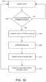
- FIG. 19is a flow chart illustrating a method for combining data of an intelligent electronic device in accordance with an embodiment of present disclosure.
- FIG. 20illustrates combining records of a data table of an intelligent electronic device in accordance with an embodiment of present disclosure.
- all functions described hereinmay be performed in either hardware or software, or some combination thereof. In one embodiment, however, the functions are performed by at least one processor, such as a computer or an electronic data processor, digital signal processor or embedded micro-controller, in accordance with code, such as computer program code, software, and/or integrated circuits that are coded to perform such functions, unless indicated otherwise.
- processorsuch as a computer or an electronic data processor, digital signal processor or embedded micro-controller
- intelligent electronic devicessense electrical parameters and compute data and can be any device including, but not limited to, Programmable Logic Controllers (“PLC's”), Remote Terminal Units (“RTU's”), electric power meters, panel meters, protective relays, fault recorders, phase measurement units, serial switches, smart input/output devices and other devices which are coupled with power distribution networks to manage and control the distribution and consumption of electrical power.
- PLC'sProgrammable Logic Controllers
- RTU'sRemote Terminal Units
- a meteris a device that records and measures power events, power quality, current, voltage waveforms, harmonics, transients and other power disturbances.
- Revenue accurate meters(“revenue meter”) relate to revenue accuracy electrical power metering devices with the ability to detect, monitor, report, quantify and communicate power quality information about the power that they are metering.
- FIG. 1is a block diagram of an intelligent electronic device (IED) 10 for monitoring and determining power usage and power quality for any metered point within a power distribution system and for providing a data transfer system for faster and more accurate processing of revenue and waveform analysis.
- IEDintelligent electronic device
- the IED 10 of FIG. 1includes a plurality of sensors 12 coupled to various phases A, B, C and neutral N of an electrical distribution system 11 , a plurality of analog-to-digital (A/D) converters 14 , including inputs coupled to the sensor 12 outputs, a power supply 16 , a volatile memory 18 , a non-volatile memory 20 , a multimedia user interface 22 , and a processing system that includes at least one central processing unit (CPU) 50 (or host processor) and one or more digital signal processors, two of which are shown, i.e., DSP 1 60 and DSP 2 70 .
- CPUcentral processing unit
- DSP 1 60 and DSP 2 70digital signal processor
- the IED 10also includes a Field Programmable Gate Array 80 which performs a number of functions, including, but not limited to, acting as a communications gateway for routing data between the various processors 50 , 60 , 70 , receiving data from the A/D converters 14 performing transient detection and capture and performing memory decoding for CPU 50 and the DSP processor 60 .
- the FPGA 80is internally comprised of two dual port memories to facilitate the various functions. It is to be appreciated that the various components shown in FIG. 1 are contained within housing 90 . Exemplary housings will be described below in relation to FIGS. 2 A- 2 H .
- the plurality of sensors 12sense electrical parameters, e.g., voltage and current, on incoming lines, (i.e., phase A, phase B, phase C, neutral N), from an electrical power distribution system 11 e.g., an electrical circuit.
- the sensors 12will include current transformers and potential transformers, wherein one current transformer and one voltage transformer will be coupled to each phase of the incoming power lines.
- a primary winding of each transformerwill be coupled to the incoming power lines and a secondary winding of each transformer will output a voltage representative of the sensed voltage and current.
- the output of each transformerwill be coupled to the A/D converters 14 configured to convert the analog output voltage from the transformer to a digital signal that can be processed by the CPU 50 , DSP 1 60 , DSP 2 70 , FPGA 80 or any combination thereof.
- A/D converters 14are respectively configured to convert an analog voltage output to a digital signal that is transmitted to a gate array, such as Field Programmable Gate Array (FPGA) 80 .
- the digital signalis then transmitted from the FPGA 80 to the CPU 50 and/or one or more DSP processors 60 , 70 to be processed in a manner to be described below.
- FPGAField Programmable Gate Array
- the CPU 50 or DSP Processors 60 , 70are configured to operatively receive digital signals from the A/D converters 14 (see FIG. 1 ) to perform calculations necessary to determine power usage and to control the overall operations of the IED 10 .
- CPU 50 , DSP 1 60 and DSP 2 70may be combined into a single processor, serving the functions of each component.
- the digital samples, which are output from the A/D converters 14are sent directly to the CPU 50 or DSP processors 60 , 70 , effectively bypassing the FPGA 80 as a communications gateway.
- the power supply 16provides power to each component of the IED 10 .
- the power supply 16is a transformer with its primary windings coupled to the incoming power distribution lines and having windings to provide a nominal voltage, e.g., 5 VDC, +12 VDC and ⁇ 12 VDC, at its secondary windings.
- powermay be supplied from an independent power source to the power supply 16 .
- powermay be supplied from a different electrical circuit or an uninterruptible power supply (UPS).
- UPSuninterruptible power supply
- the power supply 16can be a switch mode power supply in which the primary AC signal will be converted to a form of DC signal and then switched at high frequency, such as, for example, 100 Khz, and then brought through a transformer to step the primary voltage down to, for example, 5 Volts AC. A rectifier and a regulating circuit would then be used to regulate the voltage and provide a stable DC low voltage output.
- Other embodiments, such as, but not limited to, linear power supplies or capacitor dividing power suppliesare also contemplated.
- the multimedia user interface 22is shown coupled to the CPU 50 in FIG. 1 for interacting with a user and for communicating events, such as alarms and instructions to the user.
- the multimedia user interface 22may include a display for providing visual indications to the user.
- the displaymay be embodied as a touch screen, a liquid crystal display (LCD), a plurality of LED number segments, individual light bulbs or any combination.
- the displaymay provide information to the user in the form of alpha-numeric lines, computer-generated graphics, videos, animations, etc.
- the multimedia user interface 22further includes a speaker or audible output means for audibly producing instructions, alarms, data, etc.
- the speakeris coupled to the CPU 50 via a digital-to-analog converter (D/A) for converting digital audio files stored in a memory 18 or non-volatile memory 20 to analog signals playable by the speaker.
- D/Adigital-to-analog converter
- An exemplary interfaceis disclosed and described in commonly owned pending U.S. application Ser. No. 11/589,381, entitled “POWER METER HAVING AUDIBLE AND VISUAL INTERFACE”, which claims priority to expired U.S. Provisional Patent Appl. No. 60/731,006, filed Oct. 28, 2005, the contents of which are hereby incorporated by reference in their entireties.
- the IED 10will support various file types including but not limited to Microsoft Windows Media Video files (.wmv), Microsoft Photo Story files (.asf), Microsoft Windows Media Audio files (.wma), MP3 audio files (.mp3), JPEG image files (.jpg, jpeg, .jpe, .jfif), MPEG movie files (.mpeg, .mpg, .mpe, .mlv, .mp2v .mpeg2), Microsoft Recorded TV Show files (.dvr-ms), Microsoft Windows Video files (.avi) and Microsoft Windows Audio files (.wav).
- Microsoft Windows Media Video files.wmv
- Microsoft Photo Story files.asf
- Microsoft Windows Media Audio files.wma
- MP3 audio files.mp3 audio files
- JPEG image files.jpg, jpeg, .jpe, .jfif
- MPEG movie files.mpeg, .mpg, .mpe, .mlv,
- the IED 10further comprises a volatile memory 18 and a non-volatile memory 20 .
- volatile memory 18will store the sensed and generated data for further processing and for retrieval when called upon to be displayed at the IED 10 or from a remote location.
- the volatile memory 18includes internal storage memory, e.g., random access memory (RAM), and the non-volatile memory 20 includes removable memory such as magnetic storage memory; optical storage memory, e.g., the various types of CD and DVD media; solid-state storage memory, e.g., a CompactFlash card, a Memory Stick, SmartMedia card, MultiMediaCard (MMC), SD (Secure Digital) memory; or any other memory storage that exists currently or will exist in the future.
- MMCMultiMediaCard
- SDSecure Digital
- the IED 10will include a communication device 24 , also know as a network interface, for enabling communications between the IED or meter, and a remote terminal unit, programmable logic controller and other computing devices, microprocessors, a desktop computer, laptop computer, other meter modules, etc.
- the communication device 24may be a modem, network interface card (NIC), wireless transceiver, etc.
- the communication device 24will perform its functionality by hardwired and/or wireless connectivity.
- the hardwire connectionmay include but is not limited to hard wire cabling e.g., parallel or serial cables, RS232, RS485, USB cable, Firewire ( 1394 connectivity) cables, Ethernet, and the appropriate communication port configuration.
- the wireless connectionwill operate under any of the various wireless protocols including but not limited to BluetoothTM interconnectivity, infrared connectivity, radio transmission connectivity including computer digital signal broadcasting and reception commonly referred to as Wi-Fi or 802.11.X (where x denotes the type of transmission), satellite transmission or any other type of communication protocols, communication architecture or systems currently existing or to be developed for wirelessly transmitting data including spread spectrum 900 MHz, or other frequencies, Zigbee, WiFi, or any mesh enabled wireless communication.
- BluetoothTM interconnectivityinfrared connectivity
- radio transmission connectivityincluding computer digital signal broadcasting and reception commonly referred to as Wi-Fi or 802.11.X (where x denotes the type of transmission), satellite transmission or any other type of communication protocols, communication architecture or systems currently existing or to be developed for wirelessly transmitting data including spread spectrum 900 MHz, or other frequencies, Zigbee, WiFi, or any mesh enabled wireless communication.
- the IED 10may communicate to a server or other computing device via the communication device 24 .
- the IED 10may be connected to a communications network, e.g., the Internet, by any means, for example, a hardwired or wireless connection, such as dial-up, hardwired, cable, DSL, satellite, cellular, PCS, wireless transmission (e.g., 802.11a/b/g), etc.
- the networkmay be a local area network (LAN), wide area network (WAN), the Internet or any network that couples a plurality of computers to enable various modes of communication via network messages.
- the serverwill communicate using various protocols such as Transmission Control Protocol/Internet Protocol (TCP/IP), File Transfer Protocol (FTP), Hypertext Transfer Protocol (HTTP), etc.
- TCP/IPTransmission Control Protocol/Internet Protocol
- FTPFile Transfer Protocol
- HTTPHypertext Transfer Protocol
- the serverwill further include a storage medium for storing a database of instructional videos, operating manuals, etc., the details of which will be described in detail below.
- the IED 10will also have the capability of not only digitizing waveforms, but storing the waveform and transferring that data upstream to a central computer, e.g., a remote server, when an event occurs such as a voltage surge or sag or a current short circuit.
- This datawill be triggered and captured on an event, stored to memory, e.g., non-volatile RAM, and additionally transferred to a host computer within the existing communication infrastructure either immediately in response to a request from a remote device or computer to receive said data in response to a polled request.
- the digitized waveformwill also allow the CPU 50 to compute other electrical parameters such as harmonics, magnitudes, symmetrical components and phasor analysis. Using the harmonics, the IED 10 will also calculate dangerous heating conditions and can provide harmonic transformer derating based on harmonics found in the current waveform.
- the IED 10will execute an e-mail client and will send e-mails to the utility or to the customer direct on an occasion that a power quality event occurs. This allows utility companies to dispatch crews to repair the condition.
- the data generated by the metersare use to diagnose the cause of the condition.
- the datais transferred through the infrastructure created by the electrical power distribution system.
- the email clientwill utilize a POP3 or other standard mail protocol.
- a userwill program the outgoing mail server and email address into the meter.
- An exemplary embodiment of said meteringis available in U.S. Pat. No. 6,751,563, which all contents thereof are incorporated by reference herein.
- the techniques of the present disclosurecan be used to automatically maintain program data and provide field wide updates upon which IED firmware and/or software can be upgraded.
- An event commandcan be issued by a user, on a schedule or by digital communication that will trigger the IED 10 to access a remote server and obtain the new program code. This will ensure that program data will also be maintained allowing the user to be assured that all information is displayed identically on all units.
- the IED 10also includes an operating system and micro instruction code.
- the various processes and functions described hereinmay either be part of the micro instruction code or part of an application program (or a combination thereof) which is executed via the operating system.
- the components and devices of the IED 10 of FIG. 1may be disposed in various housings depending on the application or environment.
- the IED 10may be configured as a panel meter 900 as shown in FIGS. 2 A and 2 B .
- the panel meter 900 of FIGS. 2 A and 2 Bis described in more detail in commonly owned U.S. Pat. No. 7,271,996, the contents of which are hereby incorporated by reference. As seen in FIGS.
- the IED 900includes a housing 902 defining a front surface 902 a , a rear surface 902 b , a top surface 902 c , a bottom surface 902 d , a right side surface 902 e , and a left side surface (not shown).
- Electrical device 900includes a face plate 904 operatively connected to front surface 902 a of housing 902 .
- Face plate 904includes displays 906 , indicators 908 (e.g., LEDs and the like), buttons 910 , and the like providing a user with an interface for visualization and operation of electrical device 100 . For example, as seen in FIG.
- face plate 904 of electrical device 900includes analog and/or digital displays 906 capable of producing alphanumeric characters.
- Face plate 904includes a plurality of indicators 908 which, when illuminated, indicate to the user the “type of reading”, the “% of load bar”, the “parameter designation” which indicates the reading which is being displayed on displays 906 , a “scale selector” (e.g., Kilo or Mega multiplier of Displayed Readings), etc.
- Face plate 904includes a plurality of buttons 910 (e.g., a “menu” button, an “enter” button, a “down” button, a “right” button, etc.) for performing a plurality of functions, including but not limited to: viewing of meter information; entering display modes; configuring parameters; performing re-sets; performing LED checks; changing settings; viewing parameter values; scrolling parameter values; and viewing limit states.
- the housing 902includes voltage connections or inputs 912 provided on rear surface 902 b thereof, and current inputs 914 provided along right side surface 902 e thereof.
- the IED 900may include a first interface or communication port 916 for connection to a master and/or slave device. Desirably, first communication port 916 is situated in rear surface 902 b of housing 902 IED 900 may also include a second interface or communication port 918 situated on face plate 904 .
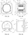
- the IED 10may be configured as a socket meter 920 , also known as a S-base type meter or type S meter, as shown in FIG. 2 C an 2 D.
- the socket meter 920 of FIGS. 2 C and 2 Dis described in more detail in commonly owned application Ser. No. 12/578,062 (U.S. Publication No. 2010/0090680), the contents of which are hereby incorporated by reference.
- the meter 920includes a main housing 922 surrounded by a cover 924 .
- the cover 924is preferably made of a clear material to expose a display 926 disposed on the main body 922 .
- the meter 920further includes a plurality of current terminals 932 and voltage terminals 934 disposed on backside of the meter extending through a base 935 .
- the terminals 932 , 934are designed to mate with matching jaws of a detachable meter-mounting device, such as a revenue meter socket.
- the socketis hard wired to the electrical circuit and is not meant to be removed. To install an S-base meter, the utility need only plug in the meter into the socket. Once installed, a socket-sealing ring 936 is used as a seal between the meter 920 and/or cover 924 and the meter socket to prevent removal of the meter and to indicate tampering with the meter.
- the IED 10 of FIG. 1may be disposed in a switchboard or draw-out type housing 940 as shown in FIGS. 2 E and 2 F , where FIG. 2 E is a front view and FIG. 2 F is a rear view.
- the switchboard enclosure 942usually features a cover 944 with a transparent face 946 to allow the meter display 948 to be read and the user interface 950 to be interacted with by the user.
- the cover 944also has a sealing mechanism (not shown) to prevent unauthorized access to the meter.
- a rear surface 952 of the switchboard enclosure 942provides connections for voltage and current inputs 954 and for various communication interfaces 956 .
- the meter disposed in the switchboard enclosure 942may be mounted on a draw-out chassis which is removable from the switchboard enclosure 942 .
- the draw-out chassisinterconnects the meter electronics with the electrical circuit.
- the draw-out chassiscontains electrical connections which mate with matching connectors 954 , 956 disposed on the rear surface 952 of the enclosure 942 when the chassis is slid into place.
- the IED 10 of FIG. 1may be disposed in an A-base or type A housing as shown in FIGS. 2 G and 2 H .
- A-base meters 960feature bottom connected terminals 962 on the bottom side of the meter housing 964 . These terminals 962 are typically screw terminals for receiving the conductors of the electric circuit (not shown).
- A-base meters 960further include a meter cover 966 , meter body 968 , a display 970 and input/output means 972 . Further, the meter cover 966 includes an input/output interface 974 .
- the cover 966encloses the meter electronics 968 and the display 970 .
- the cover 966has a sealing mechanism (not shown) which prevents unauthorized tampering with the meter electronics.
- FIG. 3illustrates an exemplary environment 100 in which the present disclosure may be practiced.
- the network 120may be the Internet, a public or private intranet, an extranet, wide area network (WAN), local area network (LAN) or any other network configuration to enable transfer of data and commands.
- An example network configurationuses the Transport Control Protocol/Internet Protocol (“TCP/IP”) network protocol suite; however, other Internet Protocol based networks are contemplated by the present disclosure.
- Communicationsmay also include IP tunneling protocols such as those that allow virtual private networks coupling multiple intranets or extranets together via the Internet.
- the network 120may support existing or envisioned application protocols, such as, for example, telnet, POP3, Mime, HTTP, HTTPS, PPP, TCP/IP, SMTP, proprietary protocols, or any other network protocols.
- the IED 110may communicate using the network 120 as will be hereinafter discussed.
- client/server networksthere are at least two basic types of networks, based on the communication patterns between the machines: client/server networks and peer-to-peer networks.
- client/server networksevery computer, device or IED has a distinct role: that of either a client or a server.
- a serveris designed to share its resources among the client computers on the network.
- a dedicated server computeroften has faster processors, more memory, and more storage space than a client because it might have to service dozens or even hundreds of users at the same time.
- High-performance serverstypically use from two to eight processors (which does not include multi-core CPUs), have many gigabytes of memory installed, and have one or more server-optimized network interface cards (NICs), RAID (Redundant Array of Independent Drives) storage consisting of multiple drives, and redundant power supplies.
- Serversoften run a special network OS—such as Windows Server, Linux, or UNIX—that is designed solely to facilitate the sharing of its resources. These resources can reside on a single server or on a group of servers. When more than one server is used, each server can “specialize” in a particular task (file server, print server, fax server, email server, and so on) or provide redundancy (duplicate servers) in case of server failure.
- a client devicetypically communicates only with servers, not with other clients.
- a client systemis a standard PC that is running an OS such as Windows.
- Current operating systemscontain client software that enables the client computers to access the resources that servers share.
- Older operating systemssuch as Windows 3.x and DOS, required add-on network client software to join a network.
- every computer or deviceis equal and can communicate with any other computer or device on the network to which it has been granted access rights.
- every computer or device on a peer-to-peer networkcan function as both a server and a client; any computer or device on a peer-to-peer network is considered a server if it shares a printer, a folder, a drive, or some other resource with the rest of the network.
- the actual networking hardwareinterface cards, cables, and so on
- Only the logical organization, management, and control of the networksvary.
- the PC client 102may comprise any computing device, such as a server, mainframe, workstation, personal computer, hand held computer, laptop telephony device, network appliance, other IED, Programmable Logic Controller, Power Meter, Protective Relay etc.
- the PC client 102includes system memory 104 , which may be implemented in volatile and/or non-volatile devices.
- client applications 106which may execute in the system memory 104 , are provided.
- client applicationsmay include, for example, FTP client applications.
- File Transfer Protocolis an application for transfer of files between computers attached to Transmission Control Protocol/Internet Protocol (TCP/IP) networks, including the Internet.
- FTPis a “client/server” application, such that a user runs a program on one computer system, the “client”, which communicates with a program running on another computer system, the “server”. Additionally, user interfaces 108 may be included for displaying system configuration, retrieved data and diagnostics associated with the IED 110 .
- the intelligent electronic device (IED) 110is comprised of at least an FTP Server 131 including a Virtual Command File Processor 133 , a File System and Driver 135 , a non-volatile memory 137 and a virtual data store 139 .
- the IED 110may contain other hardware/software for performing functions associated with the IED; however, many of these functions have been described above with respect to FIG. 1 and will therefore not be further discussed.
- IED 110runs the FTP Server 131 as an independent process in the operating system, allowing it to function independently of the other running processes. Additionally, it allows for multiple connections, using the port/socket architecture of TCP/IP.
- FTP Server 131By running the FTP Server 131 as an independent process, this means that other systems, such as a Modbus TCP handler, can run on IED 110 concurrently with the FTP Server 131 . This also means that multiple FTP connections can be made with the only limitation being the system's available resources.
- the FTP Server 131provides access to the file system 135 of the IED 110 on the standard FTP port (port 21 ).
- PC client 102sends an FTP logon sequence, which includes a USER command and a PASS command.
- the PC client 102then interacts with the IED 110 , requesting information and writing files, ending in a logout.
- the FTP Server 131uses two ports for all actions.
- the first port 21is a clear ASCII telnet channel, and is called the command channel.
- the second portwhich can have a different port number in different applications, is initiated whenever it is necessary to transfer data in clear binary, and is called the data channel.
- the virtual data store 139is an ideal storage medium for files that are written to very frequently, such as, for example, status information, diagnostics, and virtual command files.
- fileswhich require more long term storage, such as, for example, logs, settings, and configurations, more suitably stored using a compact flash drive.
- the File Transfer Protocol(FTP) (Port 21 ) is a network protocol used to transfer data from one computer to another through a network, such as over the Internet.
- FTPis a commonly used protocol for exchanging files over any TCP/IP based network to manipulate files on another computer on that network regardless of which operating systems are involved (if the computers permit FTP access).
- FTP serverscan be set up anywhere between game servers, voice servers, internet hosts, and other physical servers.
- FTPruns exclusively over TCP.
- FTP serversby default listen on port 21 for incoming connections from FTP clients.
- a connection to this port from the FTP Clientforms the control stream on which commands are passed to the FTP server from the FTP client and on occasion from the FTP server to the FTP client.
- FTPuses out-of-band control, which means it uses a separate connection for control and data.
- the data streamis required which is called the data stream.
- the process of setting up the data streamis different.
- the FTP clientopens a dynamic port (for example, 49152-65535), sends the FTP server the dynamic port number on which it is listening over the control stream and waits for a connection from the FTP server.
- a dynamic portfor example, 49152-65535
- the FTP serverinitiates the data connection to the FTP client it binds the source port to port 20 on the FTP server.
- the clientsends a PORT command, with the IP and port as argument.
- the format for the IP and portis “h1,h2,h3,h4,p1,p2”.
- Each fieldis a decimal representation of 8 bits of the host IP, followed by the chosen data port. For example, a client with an IP of 192.168.0.1, listening on port 49154 for the data connection will send the command “PORT 192,168,0,1,192,2”.
- the FTP serveropens a dynamic port (49152-65535), sends the FTP client the server's IP address to connect to and the port on which it is listening (a 16 bit value broken into a high and low byte, like explained before) over the control stream and waits for a connection from the FTP client.
- the FTP clientbinds the source port of the connection to a dynamic port between 49152 and 65535.
- the clientsends the PASV command to which the server would reply with something similar to “227 Entering Passive Mode (127,0,0,1,192,52)”.
- the syntax of the IP address and portare the same as for the argument to the PORT command.
- the FTP serveroperates exactly the same as passive mode, except that it only transmits the port number (not broken into high and low bytes) and the client is to assume that it connects to the same IP address that it was originally connected to.
- the objectives of FTPare to promote sharing of files (computer programs and/or data), to encourage indirect or implicit use of remote computers, to shield a user from variations in file storage systems among different hosts and to transfer data reliably, and efficiently.
- the IED 110has the ability to provide an external PC client 102 with an improved data transfer rate when making data download requests of data stored within an IED This is achieved by configuring the IED 110 to include an FTP server 131 including a Virtual Command File Processor 133 . An improved data transfer rate from the IED 110 may be realized by the external PC client 102 issuing virtual commands to the IED 110 . In response, the IED 110 processes the received virtual commands in the Virtual Command File processor 133 to construct FTP commands therefrom to be applied to a novel file system 135 of the IED 110 , coupled to the FTP server 131 , wherein the novel file system 135 is configured as a PC file structure amenable to receiving and responding to the constructed FTP commands.
- the Virtual command files and the novel file system 135are discussed in greater detail in co-pending application Ser. No. 12/061,979.
- FTP file transfercomprises one embodiment for encapsulating files to improve a data transfer rate from an IED to external PC clients
- present disclosurecontemplates the use of other file transfer protocols, such as the Ethernet protocol such as HTTP or TCP/IP for example.
- Ethernet protocolsare contemplated for use by the present disclosure.
- HTTP file encapsulationfor the purpose of security and firewall access, it may be preferable to utilize HTTP file encapsulation as opposed to sending the data via FTP.
- datacan be attached as an email and sent via SMTP, for example.
- At least one processor of the IED or meteris configured to collect the at least one parameter and generate data from the sampled at least one parameter, wherein the at least one processor is configured to act as a server for the IED or meter and is further configured for presenting the collected and generated data in the form of web pages.
- FIG. 4is a block diagram of a web server power quality and revenue meter 210 .
- the meteris connected to monitor electric distribution power lines (not shown), to monitor voltage and current at the point of connection.
- digital sampler 220for digitally sampling the voltage and current of the power being supplied to a customer or monitored at the point of the series connection in the power grid.
- Digital sampler 220digitally samples the voltage and current and performs substantially similarly to the A/D converters 14 described above in relation to FIG. 1 .
- the digital samplesare then forwarded to processor 230 for processing.
- the processor 230may be a single processing unit or a processing assembly including at least one CPU 50 , DSP 1 60 , DSP 2 70 and FPGA 80 , or any combination thereof. Also connected to processor 230 is external device interface 240 for providing an interface for external devices 250 to connect to meter 210 . These external devices might include other power meters, sub-station control circuitry, on/off switches, etc. Processor 230 receives data packets from digital sampler 220 and external devices 250 , and processes the data packets according to user defined or predefined requirements.
- a memory 260is connected to processor 230 for storing data packets and program algorithms, and to assist in processing functions of processor 230 .
- Processor 230provides processed data to network 280 through network interface 270 .
- Network 280can be the Internet, the World Wide Web (WWW), an intranet, a wide area network (WAN), or local area network (LAN), among others.
- the network interfaceconverts the data to an Ethernet TCP/IP format. The use of the Ethernet TCP/IP format allows multiple users to access the power meter 210 simultaneously.
- network interface 270might be comprised of a modem, cable connection, or other devices that provide formatting functions.
- Computers 290 - 292are shown connected to network 280 .
- a web server program(web server) is contained in memory 260 , and accessed through network interface 270 .
- the web server 210provides real time data through any known web server interface format.
- popular web server interface formatsconsist of HTML and XML formats.
- the actual format of the programming language usedis not essential to the present disclosure, in that any web server format can be incorporated herein.
- the web serverprovides a user friendly interface for the user to interact with the meter 210 .
- the usercan have various access levels to enter limits for e-mail alarms. Additionally, the user can be provided the data in multiple formats including raw data, bar graph, charts, etc.
- the currently used HTML or XML programming languagesprovide for easy programming and user friendly user interfaces.
- the processor 230formats the processed data into various network protocols and formats.
- the protocols and formatscan, for example, consist of the web server HTML or XML formats, Modbus TCP, RS-485, FTP or e-mail. Dynamic Host Configuration Protocol (DHCP) can also be used to assign IP addresses.
- DHCPDynamic Host Configuration Protocol
- the network formatted datamay then be available to users at computers 290 - 292 through network 280 , which connects to meter 210 at the network interface 270 .
- network interface 270is an Ethernet interface that supports, for example, 100 base-T or 10 base-T communications. This type of network interface can send and receive data packets between WAN connections and/or LAN connections and the meter 210 .
- This type of network interfaceallows for situations, for example, where the web server 210 may be accessed by one user while another user is communicating via the Modbus TCP, and a third user may be downloading a stored data file via FTP.
- the ability to provide access to the meter by multiple users, simultaneously,is a great advantage over the prior art. This can allow for a utility company's customer service personnel, a customer and maintenance personnel to simultaneously and interactively monitor and diagnose possible problems with the power service.
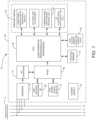
- FIG. 5is a functional block diagram of processor 230 of the web server power quality and revenue meter system according to some embodiments of the present invention.
- Processor 230is shown containing four main processing functions. The functions shown are illustrative and not meant to be inclusive of all possible functions performed by processor 230 .
- Power Quality and Revenue Metering functions (metering functions) 310consist of a complete set of functions which are needed for power quality and revenue metering. Packet data collected by digital sampler 220 is transmitted to processor 230 .
- Processor 230calculates, for example, power reactive power, apparent power, and power factor.
- the metering function 310responds to commands via the network or other interfaces supported by the meter.
- External Device Routing Functions 330handle the interfacing between the external device 250 and meter 210 .
- Raw data from external device 250is fed into meter 210 .
- the external device 250is assigned a particular address. If more than one external device is connected to meter 210 , each device will be assigned a unique particular address.
- the Network Protocol Functions 350 of meter 210are executed by processor 230 which executes multiple networking tasks that are running concurrently. As shown in FIG. 5 , these include, but are not limited to, the following network tasks included in network protocol functions 350 : e-mail 360 , web server 370 , Modbus TCP 380 , FTP 390 , and DHCP 300 .
- the e-mail 360 network protocol functioncan be utilized to send e-mail messages via the network 280 to a user to, for example, notify the user of an emergency situation or if the power consumption reaches a user-set or pre-set high level threshold.
- the processorreceives packets of data it identifies the network processing necessary for the packet by the port number associated with the packet.
- the processor 230allocates the packet to a task as a function of the port number. Since each task is running independently, the meter 210 can accept different types of requests concurrently and process them transparently from each other. For example, the web server may be accessed by one user while another user is communicating via Modbus TCP and at the same time a third user may download a log file via FTP.
- the Network to Meter Protocol Conversion Functions 340are used to format and protocol convert the different network protocol messages to a common format understood by the other functional sections of meter 210 . After the basic network processing of the packet of data, any “commands” or data which are to be passed to other functional sections of meter 210 are formatted and protocol converted to a common format for processing by the Network to Meter Protocol Conversion Functions 340 . Similarly, commands or data coming from the meter for transfer over the network are pre-processed by this function into the proper format before being sent to the appropriate network task for transmission over the network. In addition, this function first protocol converts and then routes data and commands between the meter and external devices.
- a firewallis a system designed to prevent unauthorized access to or from a private network, e.g., an internal network of a building, a corporate network, etc.
- Firewallscan be implemented in both hardware and software, or a combination of both. Firewalls are frequently used to prevent unauthorized Internet users from accessing private networks connected to the Internet, especially intranets. All messages entering or leaving the intranet pass through the firewall, which examines each message and blocks those that do not meet the specified security criteria.
- a firewallmay employ one or more of the following techniques to control the flow of traffic in and of the network it is protecting: 1) packet filtering: looks at each packet entering or leaving the network and accepts or rejects it based on user-defined rules; 2) Application gateway: applies security mechanisms to specific applications, such as FTP and Telnet servers; 3) Circuit-level gateway: applies security mechanisms when a TCP or UDP connection is established; once the connection has been made, packets can flow between the hosts without further checking; 4) Proxy server: intercepts all messages entering and leaving the network, effectively hides the true network addresses; and 5) Stateful inspection: does not examine the contents of each packet but instead compares certain key parts of the packet to a database of trusted information; if the comparison yields a reasonable match, the information is allowed through; otherwise it is discarded. Other techniques and to be developed techniques are contemplated to be within the scope of the present disclosure.
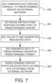
- the present disclosureprovides for overcoming the problem of not being allowed firewall access to an IED or meter installed within a facility, i.e., the meter is residing on a private network, by enabling an IED to initiate one way communication through the firewall.
- the IED or meterposts the monitored and generated data on an Internet site external to the corporate or private network, i.e., on the other side of a firewall.
- the benefitis that any user would be able to view the data on any computer or web enabled smart device without having to pierce or bypass the firewall.
- the features of this embodimentcan be incorporated into any telemetry application including vending, energy metering, telephone systems, medical devices and any application that requires remotely collecting data and posting it on to a public Internet web site.
- the IED or metering devicewill communicate through the firewall using a protocol such as HTTP via a port that is open through the firewall.
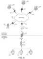
- IEDs or meters 410 , 412 414reside on an internal network 416 , e.g., an intranet, private network, corporate network, etc.
- the internal network 416is coupled to an external network 422 , e.g., the Internet, via a router 420 or similar device over any known hardwire, fiber optic or wireless connection 421 .
- a firewall 418is disposed between the internal network 416 and external network 422 to prevent unauthorized access from outside the internal network 416 to the IEDs or meters 410 , 412 , 414 .
- firewall 418is shown between the internal network 416 and the router 420 it is to be appreciated that other configurations are possible, for example, the firewall 418 being disposed between the router 420 and external network 422 . In other embodiments, the firewall 418 and router 420 may be configured as a single device. It is further to be appreciated that firewall 418 can be implemented in both hardware and software, or a combination of both.
- the communication device or network interface of the meter(as described above in relation to FIG. 1 ) will communicate through the firewall 418 and read a web site server 424 .
- the one way communication from the IED through the firewallmay be enabled by various techniques, for example, by enabling outbound traffic to the IP address or domain name of the server 424 or by using a protocol that has been configured, via the firewall settings, to pass through the firewall such as HTTP (Hyper Text Transfer Protocol), IP (Internet Protocol), TCP (Transmission Control Protocol), FTP (File Transfer Protocol), UDP (User Datagram Protocol), ICMP (Internet Control Message Protocol), SMTP (Simple Mail Transport Protocol), SNMP (Simple Network Management Protocol), Telnet, etc.
- HTTPHyper Text Transfer Protocol
- IPInternet Protocol
- TCPTransmission Control Protocol
- FTPFile Transfer Protocol
- UDPUser Datagram Protocol
- ICMPInternet Control Message Protocol
- SMTPSimple Mail Transport Protocol
- SNMPSimple Network Management Protocol
- the IEDmay have exclusive access to a particular port on the firewall, which is unknown to other users on either the internal or external network.
- Other methods or techniquesare contemplated, for example, e-mail, HTTP tunneling, SNTP trap, MSN, messenger, IRQ, TwitterTM, Bulletin Board System (BBS), forums, Universal Plug and Play (UPnP), User Datagram Protocol (UDP) broadcast, UDP unicast, Virtual Private Networks (VPN), etc.
- the server 424will provide instructions in computer and/or human readable format to the IED or meter.
- the web server 424might have XML tags that state in computer readable format to provide data for the last hour on energy consumption by 15 minute intervals.
- the meter 410 , 412 , 414will then read those instructions on that web server 424 and then post that data up on the server 424 .
- the IED or meterinitiates communication in one direction, e.g., an outbound direction, to the server 424 .
- Another server(or possibly the same server) will read the data that the meter 410 , 412 , 414 posts and will format the meter data into data that can be viewed for humans on a web site or a software application, i.e., UI Server 426 .
- Servers 424 , 426can also store the data in a database or perform or execute various control commands on the data.
- Clients 428may access the IED data stored or posted on servers 424 , 426 via a connection to the network 422 .
- the meters 410 , 412 , 414can read data or instructions from an external network application (e.g., server 424 ), but the external network application cannot request information directly from the meter.
- the server 424posts the data or instructions on the web site and waits for the meter to check the site to see if there has been a new post, i.e., new instructions for the meter.
- the metercan be programmed at the user's discretion as to frequency for which the meter 410 , 412 , 414 exits out to the external network to view the postings.
- the meter instruction server 424will post instructions in a directory programmed/located on the server or into XML or in any fashion that the meter is configured to understand and then the meter will post whatever data it is instructed to do.
- the metercan also be configured to accomplish control commands.
- a user interface (UI) server 426is provided that can be used to enable a user interface to the user. The user can provide input on the UI server 426 that might trigger the meter instruction server 424 to produce a message to control the energy next time the meter reads that server.
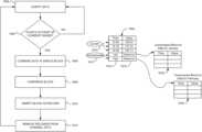
- a method for communicating data from an IED on an internal network to a server on an external network through a firewallis illustrated.
- the IED 410communicates through the firewall 418 to a predetermined server 424 on an external network 422 .
- the IED 410may be programmed to periodically communicate to the server at predefined intervals.
- the IED 410reads instructions disposed in a directory or folder on the predetermined server 424 , step 454 .
- step 456the IED 410 collects data from its internal memory or generates data based on the read instructions.
- the IED 410then transmits the data to the server 424 in a predetermined format, e.g., extensible markup language (XML), comma-separated value (CSV), etc., step 458 .
- the predetermined server 424posts the received data on a web site accessible from the external network 422 .
- the datamay be posted on the server 424 or a UI (user interface) server 426 configured to provide data for end users, e.g., clients 428 .
- the UI server 426may be configured to post data from several locations in one convenient interface for, for example, an organization managing the several locations.
- a provider of the servers 424 , 426may charge a fee to the end user for the hosting of the web site and providing the data in a convenient and accessible format.
- the IED or metering devicewill communicate through the firewall using a server 530 disposed on an internal network protected by a firewall.
- IEDs or meters 510 , 512 , 514reside on an internal network 516 , e.g., an intranet, private network, corporate network, etc.
- the internal network 516is coupled to an external network 522 , e.g., the Internet, via a router 520 or similar device over any known hardwire or wireless connection 521 .
- a firewall 518is disposed between the internal network 516 and external network 522 to prevent unauthorized access from outside the internal network 516 to the IEDs or meters 510 , 512 , 514 .
- firewall 518is shown between the internal network 516 and the router 520 it is to be appreciated that other configurations are possible, for example, the firewall 518 being disposed between the router 520 and external network 522 . In other embodiments, the firewall 518 and router 520 may be configured as a single device. It is further to be appreciated that firewall 518 can be implemented in both hardware and software, or a combination of both.
- server 530aggregates data from the various IEDs 510 , 512 , 514 coupled to the internal or private network 516 . Since the server 530 and the IEDs 510 , 512 , 514 are all on the same side of the firewall 518 , generally communications and data transfers among the server 530 and the IEDs 510 , 512 , 514 is unrestricted. Server 530 then communicates or transfers the data from the IEDs to server 524 on the external network on the other side of the firewall 518 . The communication between servers 530 and 524 may be accomplished by any one of the communication means or protocols described in the present disclosure. The server 524 then posts the data from the IEDs 510 , 512 , 514 making the data accessible to clients 528 on external networks, as described above.
- the IED or metering devicewill communicate through the firewall using a server 630 disposed on an internal network protected by a firewall.
- IEDs or meters 610 , 612 , 614reside on an internal network 616 , e.g., an intranet, private network, corporate network, etc.
- the internal network 616is coupled to an external network 622 , e.g., the Internet, via a router 620 or similar device over any known hardwire or wireless connection 621 .
- a firewall 618is disposed between the internal network 516 and external network 622 to prevent unauthorized access from outside the internal network 616 to the IEDs or meters 610 , 612 , 614 .
- firewall 618is shown between the internal network 616 and the router 620 it is to be appreciated that other configurations are possible, for example, the firewall 618 being disposed between the router 620 and external network 622 . In other embodiments, the firewall 618 and router 620 may be configured as a single device. It is further to be appreciated that firewall 618 can be implemented in both hardware and software, or a combination of both.
- server 630aggregates data from the various IEDs 610 , 612 , 614 coupled to the internal or private network 616 . Since the server 630 and the IEDs 610 , 612 , 614 are all on the same side of the firewall 618 , generally communications and data transfers among the server 630 and the IEDs 610 , 612 , 614 is unrestricted. Server 630 then communicates or transfers the data from the IEDs to clients 628 on the external network on the other side of the firewall 618 . The communication between server 630 and clients 628 may be accomplished by any one of the communication means or protocols described in the present disclosure.
- each IED 610 , 612 , 614may be configured to act as a server to perform the functionality described above obviating the need for server 630 .
- each IED 610 , 612 , 614 and each client device 628may be configured as a server to create a peer-to-peer network, token ring or a combination of any such topology.
- the systems and methods of the present disclosuremay utilize one or more protocols and/or communication techniques including, but not limited to, e-mail, File Transfer Protocol (FTP), HTTP tunneling, SNTP trap, MSN, messenger, IRQ, TwitterTM, Bulletin Board System (BBS), forums, Universal Plug and Play (UPnP), User Datagram Protocol (UDP) broadcast, UDP unicast, Virtual Private Networks (VPN), etc.
- FTPFile Transfer Protocol
- HTTP tunnelingSNTP trap
- MSNmessenger
- IRQIRQ
- TwitterTMBulletin Board System
- BSSBulletin Board System
- UPSUniversal Plug and Play
- UDPUser Datagram Protocol
- VPNVirtual Private Networks
- each IEDsends data to a recipient via electronic mail, also known as email or e-mail.
- An Internet email messageconsists of three components, the message envelope, the message header, and the message body.
- the message headercontains control information, including, minimally, an originator's email address and one or more recipient addresses. Usually descriptive information is also added, such as a subject header field and a message submission date/time stamp.
- Network-based emailwas initially exchanged on the ARPANET in extensions to the File Transfer Protocol (FTP), but is now carried by the Simple Mail Transfer Protocol (SMTP), first published as Internet standard 10 (RFC 821) in 1982.
- FTPFile Transfer Protocol
- RRC 821Simple Mail Transfer Protocol
- SMTPcommunicates delivery parameters using a message envelope separate from the message (header and body) itself.
- Messagesare exchanged between hosts using the Simple Mail Transfer Protocol with software programs called mail transfer agents (MTAs); and delivered to a mail store by programs called mail delivery agents (MDAs, also sometimes called local delivery agents, LDAs).
- MTAssoftware programs
- MDAsmail delivery agents
- Userscan retrieve their messages from servers using standard protocols such as POP or IMAP, or, as is more likely in a large corporate environment, with a proprietary protocol specific to Novell Groupwise, Lotus Notes or Microsoft Exchange Servers.
- Webmail interfacesallow users to access their mail with any standard web browser, from any computer, rather than relying on an email client.
- Mailcan be stored on the client, on the server side, or in both places.
- Standard formats for mailboxesinclude Maildir and mbox.
- Several prominent email clientsuse their own proprietary format and require conversion software to transfer email between them.
- Server-side storageis often in a proprietary format but since access is through a standard protocol such as IMAP, moving email from one server to another can be done with any MUA supporting the protocol.
- the IEDcomposes a message using a mail user agent (MUA).
- the IEDenters the email address of a recipient and sends the message.
- the MUAformats the message in email format and uses the submission Protocol (a profile of the Simple Mail Transfer Protocol (SMTP), see RFC 6409) to send the message to the local mail submission agent (MSA), for example, run by the IED's internet service provider (ISP).
- the MSAlooks at the destination address provided in the SMTP protocol (not from the message header).
- An Internet email addressis a string of the form “recipient@meter.” The part before the “@” symbol is the local part of the address, often the username of the recipient, and the part after the “@” symbol is a domain name or a fully qualified domain name.
- the MSAresolves a domain name to determine the fully qualified domain name of the mail exchange server in the Domain Name System (DNS).
- DNSDomain Name System
- the DNS server for the domainresponds with any MX records listing the mail exchange servers for that domain, for example, a message transfer agent (MTA) server run by the recipient's ISP.
- MTAmessage transfer agent
- the MSAsends the message to MTA using SMTP. This server may need to forward the message to other MTAs before the message reaches the final message delivery agent (MDA).
- MDAfinal message delivery agent
- the MDAdelivers it to the mailbox of the recipient.
- the recipientretrieves the message using either the Post Office Protocol (POP3) or the Internet Message Access Protocol (IMAP4).
- POP3Post Office Protocol
- IMAP4Internet Message Access Protocol
- e-mail systemsmay also be employed, for example, web-based email, POP3 (Post Office Protocol 3) email services, IMAP (Internet Message Protocol) e-mail servers, and MAPI (Messaging Application Programming Interface) email servers to name a few.
- POP3Post Office Protocol 3
- IMAPInternet Message Protocol
- MAPIMobile Application Programming Interface
- File Transfer Protocolmay be employed. Techniques for transferring data from an IED to a device is described in commonly owned pending U.S. patent application Ser. No. 12/061,979, the contents of which are incorporated by reference.
- IEDsemploy Universal Plug and Play (UPnP) protocol, which is a set of networking protocols that permits networked devices to discover each other's presence, and notify clients of services available on these devices.
- UDPUniversal Plug and Play
- UPnPtakes the form of UDP broadcast messages, which are sent across a local network, to notify other devices of available services, and http requests to query the details of those devices and services.
- UPnPis employed to allow the network addresses of devices, such as meters, to automatically be discovered by a client. This enables the client software to display a list of all devices which are available. In addition, this could also allow the client software to enable the user to connect to these devices, without having to configure the network address of that device.
- the UPnP notifymay be used to indicate the health status of the device, including starting up, running, errors in configuration, and resetting.
- UPnPis employed to allow devices, such as meters, to notify the clients of what services they support, such as Modbus, dnp, web, ftp, log download, and data streaming.
- Thiscould be extended by including information particular to that service or protocol, such as to allow the client to interface with that service with no user input. This could enable the client software to display the device such that the user can focus on the details of the device, rather then worrying about the minutiae of connection information.
- an automated serveris configured to perform actions related to these automatically discovered services, such as retrieving real time information, downloading logs, or registering for notification of events.
- a server 530could be on a network 516 to collect log information from meters 510 , 512 , 514 , and whenever a meter broadcast that it provided log data, the server 530 could automatically collect that data from the meter.
- the server 530could automatically poll and log the real-time readings of all meters on the network, automatically including them as they become available on the network.
- the server 530may then post the data to server 524 .
- the server 530may automatically download new firmware, retrieve files and change or modify programmable settings in the meters 510 , 512 , 514 .
- HTTP tunnelingis employed to send a message (including the IED's or meter's data) to a server, which listens for such messages, and parses out the IED's or meter's data. This could be performed by embedding the meter's data in a HTTP message, which could be sent to the server, for example, server 424 as shown in FIG. 6 .
- the HTTP wrapperwould allow this data to pass through firewalls which only allow web traffic.
- IED 410may send a HTTP message containing measured or calculated data through firewall 418 to server 424 or server 430 .
- server 530may collect data from the various IEDs 510 , 512 , 514 and forward the collected data in a HTTP message through firewall 518 to server 524 .
- server 630is the destination (and collects) the messages generated from the various IEDs 610 , 612 , 614 , but device 628 is a client, and without server software, would be unable to receive the messages. However, by programming device 628 with server software, the client device 628 becomes a server and can receive the messages.
- the HTTP messagecan be sent based on various triggers including, but not limited to, time-based trigger, event-based trigger, storage capacity based trigger, etc.
- the IEDscan communicate through to devices using a Simple Network Management Protocol (SNMP) trap.
- SNMP trapsenable an agent, e.g., an agent running on an IED, to notify a management station, e.g., a server, of significant events by way of an unsolicited SNMP message.
- a management statione.g., a server
- NMSnetwork management system
- the managerdisplays it and can choose to take an action based on the event. For instance, the manager can poll the agent or IED directly, or poll other associated device agents to get a better understanding of the event.
- the management systemFor the management system to understand a trap sent to it by an agent, the management system must know what the object identifier (OID) of the trap or message defines. Therefore, the management system or server must have the Management Information Base (MIB) for that trap loaded. This provides the correct OID information so that the network management system can understand the traps sent to it. Additionally, a device does not send a trap to a network management system unless it is configured to do so. A device must know that it should send a trap. The trap destination is usually defined by an IP address, but can be a host name, if the device is set up to query a Domain Name System (DNS) server.
- DNSDomain Name System
- Common chat protocolssuch as MSN, AIM, IRQ, IRC, and Skype, could be used to send a message, containing the meter's data, to a public chat server, e.g., server 440 , 540 , 640 , which could then route that message to any desired client.
- a public chat servere.g., server 440 , 540 , 640
- Another possible implementationcould be to have a special client that listens for these messages, parses the data contents, and presents them as another manner.
- the messagesare proprietary format Ethernet messages, typically sent over TCP. It is to be appreciated that the actual format depends on the specific chat protocol.
- a public social server that supports a common web interface for posting informationcould be used to post a status, containing the meter's data, to a user on the public social server for that service, e.g., server 440 , 540 , 640 .
- This postcould then be viewed by the clients to see the meter's data, or read by another server for further parsing and presentation.
- the HTTP interfacecould be used, which would work the same way as users updating it from their browser (HTTP push).
- a public social serversuch as the system employed by Facebook may be utilized to post the IEDs data so the data is accessible on the external network outside of the firewall.
- Facebookuses a variety of services, tools and programming languages to make up its infrastructure which may be employed in the systems and methods of the present disclosure to implement the technique described herein.
- the serversrun a LAMP (Linux, Apache, MySQL and PHP) stack with Memcache.
- Linuxis a Unix-like operating system kernel. It is open source, highly customizable, and good for security.
- Facebook's serverruns the Linux operating system Apache HTTP server.
- MySQLis used primarily as a key store of value when the data are randomly distributed among a large number of cases logical.
- Memcacheis a caching system that is used to accelerate dynamic web sites with databases (like Facebook) by caching data and objects in RAM to reduce reading time. Memcache is the main form of caching on Facebook and helps relieve the burden of database. Having a caching system allows Facebook to be as fast as it is to remember information. Furthermore, Facebook backend services are written in a variety of different programming languages like C++, Java, Python, and Erlang.
- Thrifta lightweight remote procedure call framework for scalable cross-language services development, which supports C++, PHP, Python, Perl, Java, Ruby, Erlang, and others
- Escribanoserver logs
- Cassandradatabase
- HipHop for PHPa transformer of source code for PHP script code and was created to save server resources, HipHop transforms PHP source code in C++ optimized, among others.
- a public web sitee.g., hosting on server 440 , 540 , 640 , which allows the posting of information, such as a Forum, could be used to post a message, containing the meter's data, to a group, thread, or other location. This post would take place by a HTTP POST to the web site's server, where by the server would store that information, and present it on the web site. This message could then be viewed by the clients to see the meter's data, or read by another server for further parsing and presentation.
- the HTTP interfacecould be used, which would work the same way as users updating it from their browser (HTTP push).
- UDPUser Datagram Protocol
- messagescould be sent from the IEDs or meters to a server, e.g., servers 530 , 630 , since UDP broadcasts do not work across networks.
- the messages containing the IED's or meter's datacan then be sent to external networks via any of the described (or to be developed) communication methods.
- a UDP unicastcould support sending to any server, e.g., server 424 , 524 .
- a Virtual Private Networkcould be created such that each meter on the internal network is part of the same virtual private network as each of the clients.
- a Virtual Private Networkis a technology for using the Internet or another intermediate network to connect computers to isolated remote computer networks that would otherwise be inaccessible.
- a VPNprovides security so that traffic sent through the VPN connection stays isolated from other computers on the intermediate network.
- VPNscan connect individual IEDs or meters to a remote network or connect multiple networks together. Through VPNs, users are able to access resources on remote networks, such as files, printers, databases, or internal websites. VPN remote users get the impression of being directly connected to the central network via a point-to-point link. Any of the other described (or to be developed) protocols could then be used to push data to another server or clients on the VPN.
- Hosted data servicessuch as a hosted database, cloud data storage, Drop-Box, or web service hosting, could be used as an external server to store the meter's data.
- Hosted data servicescan be referred to as Hosting.
- Each of these Hostse.g., servers 440 , 540 , 640 , could then be accessed by the clients to query the Hosted Data.
- Many of these hosted data servicessupport HTTP Push messages to upload the data, or direct SQL messages.
- a hosted data servicecould be further extended by placing proprietary software on them, thus allowing them to act as the external meter server for any of the previously mentioned methods (e.g., servers 424 , 524 ).
- the IEDscan communicate to devices using Generic Object Oriented Substation Event (GOOSE) messages, as defined by the IEC-61850 standard, the content of which are herein incorporated by reference.
- a GOOSE messageis a user-defined set of data that is “published” on detection of a change in any of the contained data items sensed or calculated by the IED. Any IED or device on the LAN or network that is interested in the published data can “subscribe” to the publisher's GOOSE message and subsequently use any of the data items in the message as desired.
- GOOSEis known as a Publish-Subscribe message. With binary values, change detect is a False-to-True or True-to-False transition.
- IEC61850defines a “deadband” whereby if the analog value changes greater than the deadband value, a GOOSE message with the changed analog value is sent.
- a “keep alive” messageis periodically sent by the publisher to detect a potential failure.
- the keep-alive messagethere is a data item that indicates “The NEXT GOOSE will be sent in XX Seconds” (where XX is a user definable time). If the subscriber fails to receive a message in the specified time frame, it can set an alarm to indicate either a failure of the publisher or the communication network.
- the GOOSE messageobtains high-performance by creating a mapping of the transmitted information directly onto an Ethernet data frame.
- IPInternet Protocol
- TCPTransmission Control Protocol
- an Ethernet addressknown as a Multicast address is used.
- a Multicast addressis normally delivered to all devices on a Local Area Network (LAN). Many times, the message is only meant for a few devices and doesn't need to be delivered to all devices on the LAN.
- LANLocal Area Network
- the concept of a “Virtual” LAN or VLANis employed.
- the GOOSE protocolautomatically repeats messages several times without being asked. As such, if the first GOOSE message gets lost (corrupted), there is a very high probability that the next message or the next or the next will be properly received.
- the above-described one-way communication embodimentsmay apply to systems other than for energy metering.
- the present disclosuremay be applied to a vending machine or system, wherein the vending machine located in a building or structure having a private or corporate network.
- the vending machinewill include, among other data collecting components, at least a communication device or network interface as described above.
- the communication device or network interfacewill coupled the vending machine to the internal network which may be further coupled to the Internet via a firewall.
- the vending machinemay vend or dispense a plurality of items, such as soda cans, candy bars, etc., similar to the vending machine described in U.S. Pat. No. 3,178,055, the contents of which are incorporated by reference.
- the vending machinewill monitor and collect data related to the items sold. Such data may include quantities of items sold, a re-stock limit that has been reached, total revenue generated by the vending machine, etc.
- the vending machinewill post to a web site, residing on a server outside of the internal network such as the Internet, quantities of specific items sold by the vending machine that are required to fill the vending machine. In this manner, an operator that maintains the vending machine can check the web site before going to the location of the vending machine and know exactly how many items are required to fill the vending machine before going to the location to refill the vending machine.
- the teachings of the present disclosuremay be applied to a medical device, for example, a medical monitoring device configured to be worn on a patient.
- the medical monitoring devicewill include at least a communication device or network interface as described above and monitor a certain parameter relating to a patient, e.g., a heartbeat.
- the at least a communication device or network interfaceoperates on a wireless connection and coupled the medical monitoring device to internal network (e.g., a home network) which may be further coupled to the Internet via a firewall, e.g., a router provided by the Internet Service Provider.
- the medical monitoring devicewill communicate to and post the monitored data on a remote website. A user such as a doctor may then view the data of the patient by accessing the web site and not directly connecting to the medical monitoring device.
- Other embodimentsmay include security systems such as fire alarm systems, security alarm systems, etc., which need to report data. Also envisioned are manufacturing sensing equipment, traffic sensing equipment, scientific instrumentation or other types of reporting instrumentation.
- IEDse.g., meters, vending machines, medical monitoring device, etc.
- present disclosureBased on the sensitivity of the data being communicated and posted through the firewall to various external networks, various data security techniques are employed by the IEDs (e.g., meters, vending machines, medical monitoring device, etc.) contemplated by the present disclosure, some of which are described below.
- the original FTP specificationis an inherently insecure method of transferring files because there is no method specified for transferring data in an encrypted fashion. This means that under most network configurations, user names, passwords, FTP commands and transferred files can be “sniffed” or viewed by anyone on the same network using a packet sniffer. This is a problem common to many Internet protocol specifications written prior to the creation of SSL such as HTTP, SMTP and Telnet.
- SSLSecure Socket Transfer Protocol
- FTPSFTP over SSL
- the FTP server 131 in the IED 110 shown in FIG. 3uses a set of username and passwords which are programmed through Modbus. These username and passwords can only be programmed when a user performs a logon with administrative rights. Each programmed user account can be given differing permissions, which grant or restrict access to different roles within the file system. Each role controls read and write access to specific files and directories within the file system through FTP. These roles can be combined to customize the access a specific user is given. When passwords are disabled by the user, a default user account is used, with full permissions, and a username and password of “anonymous”.
- Password protection schemesare measured in terms of their password strength which may be defined as the amount of resiliency a password provides against password attacks. Password strength can be measured in bits of entropy. Password strength is an important component of an overall security posture, but as with any component of security, it is not sufficient in itself. Strong passwords can still be exploited by insider attacks, phishing, keystroke login, social engineering, dumpster diving, or systems with vulnerabilities that allow attackers in without passwords. To overcome these drawbacks it is contemplated to use some form of password encryption scheme (e.g., 8-bit, 10-bit, 16-bit) in concert with the password protection system to facilitate secure communication between an external device, such as PC client 102 and the FTP server 131 .
- some form of password encryption schemee.g., 8-bit, 10-bit, 16-bit
- a username and passwordmay be encoded as a sequence of base-64 characters.
- an encrypted connection schemeis used.
- the FTP server 131 in the TED 110uses some form of FTP security encryption, such as, for example, FTPS (FTP over SSL), Secure FTP (sometimes referred to as FTP over SSH, i.e., FTP over Secure Shell encryption (SSH)), Simple File Transfer Protocol (SFTP), or SSH file transfer protocol (SFTP).
- FTP security encryption protocolprovides a level of security unattainable with the previously described password encryption schemes.
- FTP over SSHrefers to tunneling a normal FTP session over an SSH connection.
- FTPuses multiple TCP connections, thus it is particularly difficult to tunnel over SSH.
- the FTP software at either endwill set up new TCP connections (i.e., data channels) which will bypass the SSH connection, and thus have no confidentiality, integrity protection, etc.
- the FTP cliente.g., PC client 102
- the FTP client softwareis configured to use passive mode and to connect to a SOCKS server interface, it is possible to run all the FTP channels over the SSH connection. Otherwise, it is necessary for the SSH client software to have specific knowledge of the FTP protocol, and monitor and rewrite FTP control channel messages and autonomously open new forwardings for FTP data channels.
- the networksmay be configured to adhere to cyber security standards to minimize the number of successful cyber security attacks.
- the cyber security standardsapply to devices, IEDs, computers and computer networks.
- the objective of cyber security standardsincludes protection of information and property from theft, corruption, or natural disaster, while allowing the information and property to remain accessible and productive to its intended users.
- cyber security standardsmeans the collective processes and mechanisms by which sensitive and valuable information and services are protected from publication, tampering or collapse by unauthorized activities or untrustworthy individuals and unplanned events respectively.
- the systems, devices and methodsmay be configured to be in accordance with, for example, the Standard of Good Practice (SoGP) as defined by the Information Security Forum, Critical Infrastructure Protection (CIP) standards as defined by the North American Electric Reliability Corporation (NERC), and the ISA-99 standard as defined by the International Society for Automation (ISA), the contents of each being incorporated by reference herein.
- SoGPStandard of Good Practice
- CIPCritical Infrastructure Protection
- ISA-99Standard of Good Practice
- the IED or metering deviceuses a general purpose operating system, e.g., LinuxTM, as its base.
- the IEDprovides communications on both network and serial interfaces, including Modbus, DNP, and HTTP.
- the IEDmonitors both three phase voltage and current, analyzes those values, and records the values in a log. These live values can then be retrieved using the aforementioned communications protocol, or as a log of values.
- Each of the metering functionsare added on top of the operating system as applications, each of which provides a service.
- applicationseach of which provides a service.
- a Modbus server applicationwould provide Modbus support
- a web server applicationwould provide web page support
- a logging applicationwould provide data and event logging, etc., the details of which are described below.
- the IED of the present disclosureprovides a platform which can be rapidly expanded and extended to add new functionality, and be quickly ported between platforms.
- a general purpose operating systemis employed, which provides two benefits: (1) functionality can be implemented as individual applications on top of the operating system, and (2) only the underlying drivers need be changed when porting to a new platform.
- the IEDprovides logging to keep a record of readings and events for as long as there is room to store them.
- the IEDstores the records independent of current settings, which makes the records more resistant to system errors that would lead to invalid log items.
- the IED of the present disclosureis self contained—such that it could be configured, calibrated and tested, log retrieved, real time readings viewed, and statuses checked—all without requiring a specialized software and/or hardware to be employed. This frees up the software to focus on the larger picture of how all the meters, for example, in a network, work together.
- the system architecture 1000is composed of 6 layers, each of which adds functionality on top of the previous.
- the layers, from lowest to highest,are as follows:
- Hardware 1002The hardware provides the physical metering capabilities, including measuring voltage, current, and high speed inputs, as well as providing the physical interface for the communications media, such as serial and networking.
- the DSP 1004collects the data from the metering hardware, analyzes it, and passes it up to the higher layers.
- Drivers 1006Provides the actual implementation of the hardware specific interfaces, such that the higher layers do not need to know the details of the hardware they are running on top of.
- Kernel 1008The general purpose operating system which runs the applications, and provides the connection between the drivers, and the applications. Additionally isolates the applications from the hardware to enforce a more stringent security policy.
- Applications 1010The applications that provide the primary functionality of the meter, including logging, configuration, and communications.
- the application layeralso provides internal data storage, system maintenance, and system stability monitoring functionality.
- IU 1012The interface to the outside world provided by the applications, including communications protocols such as Modbus, and UI (user interface) services such as a Web Server.
- communications protocolssuch as Modbus
- UIuser interface
- metering deviceshave been implemented using custom firmware, often which interacts directly with the hardware, and only implements and supports what is directly needed for that device when it is designed. Additionally, these implementations are often written such that all functionality is provided by a single component. This is often called a monolithic architecture. This often leads to problems when trying to expand the functionality of the device. One side effect of a monolithic architecture is that it often results in the problem that changing one component affects many of the other components. Another problem occurs when trying to port the functionality of the device to another platform. This can occur when the hardware of the device's design changes, or when the code is ported to an entirely new device. Because the firmware was written to directly access the hardware, significant modifications need to be made for it to work on the new hardware.
- the IED of the present disclosureemploys a general purpose operating system as the base for the components of the IED's firmware to facilitate expansion and porting of the IED
- the general purpose operating systemmay be, but is not limited to, LinuxTM. It is to be appreciated that a custom operating system may be implemented, which performs the components described below.
- an IED 1100including a general purpose operating system 1102 executing on a CPU 1103 in accordance with an embodiment of the present disclosure.
- the general purpose operating system 1102includes a set of code which provides the following components:
- Hardware Drivers 1104Code which implements the hardware specific functionality, while providing a common interface that the other components can use.
- Kernel 1106The central code which starts up the system, and manages the other operating system components; provides functionality pertinent to the running of the operating system.
- Process Management 1008Management system which allows arbitrary code to run, and ensures that each code block, called a process or application, shares equal time, and is isolated from one another.
- Data Storage System 1010A method to read and write data from a long term storage media 1112 .
- the binary of the processes, also know as applications 1106are often stored here, separate from the kernel.
- Support Applications 1114Code which implements support functions of the operating system but not specific applications for metering applications.
- an applicationmay provide a Modbus Server.
- an applicationmay provide a Web Server.
- an applicationmay provide data logging.
- an application 1116may be further extended by keeping the functionality of each application separate from the functionality of another application, such that any one application can be stopped without causing the other applications to lose significant functionality.
- an application 1116may encapsulate all the support tools required by the application inside the application itself, with the exception of the common or support tools 1114 provided by the general purpose operating system.
- the Modbus server applicationmay contain the code to access the network interface provided by the operating system.
- an applicationmay contain the code to interface with the file system.
- This implementationcould be improved by allowing the support code included to be loaded from a common source, e.g., a library, such that each of these applications that use such tools would use the same code, but loaded independently, such that they do not rely on each other.
- the network interface applicationcould be supplied as a Library loaded by the Modbus server; the same Library could then be used by the Web Server, such that the code is the same, but the two instances of the Library do not rely on each other.
- Another implementationwhich could be used along side the above-described implementation, may be to use long term storage, such as a file system, to pass information between applications, using a data storage mechanism, such as a database.
- This implementationallows applications to pass useful data between each application, but even if one application stops running, the other application can continue providing it's functionality.
- the meters readingscould be stored in a database, and the Modbus server application then scans or searches the database for the current readings.
- This implementationmay be further extended by allowing applications to start and stop without modifying the contents of these long term storage files.
- This implementationallows an application to be configured such that it can continue to provide it's functionality, even if the application that provides the information is unreliable or runs infrequently.
- the data logging applicationcould be designed to only run when a data record needs to be captured, saving system resources. The logged data would still be available to the other applications that use the logged data, such as the Web Server application or Modbus Server application.
- the TEDallows applications to use the logged data even if the entire system is unreliable. For example, the input power to the device may be turning on and off, causing the device to reset occasionally.
- the logging applicationcould record readings before the Web Server application was available to present the log data to a requesting client.
- the Web Server applicationcan still provide the last available readings, even should the system of the IED reset.
- a Data Filemay be configured such that the format of that file is in a common format, such that each application that wants to use that file can easily be implemented.
- a formatting applicationformats the data and/or data file into a common format. For example, instead of storing the readings data in the log data file as an explicit record that stores Voltage and Current readings, the data may be configured as a record that stores a single reading, such that another application may be added that stores Power, without modifying the format of that data file.
- the use of a data filecould be used to further improve the applications by allowing the application to store information about the current state of the application in the data file. Then, when the application restarted, the application may load those settings, and quickly resume what it was doing. For example, an application that uploads log data to an FTP server could keep track of what data it had already uploaded; if it reset halfway through, it could resume from the last file it uploaded. As another example, an application which downloaded updates to the system could keep track of what parts of the update file it retrieved, and could resume with the parts it doesn't have if a problem occurred.
- firmwarethat uses a monolithic architecture
- a component of the systemmust be updated, for example, a bug was fixed.
- a new featurewas added.
- the configuration of a componentsuch as enabling or disabling settings of a feature, may have changed.
- the most common solutionis to reset the entire system, even when the change was unrelated to other components of the system. For example, a bug fix in the Modbus server would not require the web server to reset.
- the IEDenables individual applications to start and stop independently of other applications. For example, if the binary for the Modbus Server application needed to be updated, the binary could be updated, and then just the Modbus Server application restarted, without requiring that the web server application, which is unrelated, be restarted. As another example, this could be done for a change in the configuration of the application, such as changing the Modbus map which the Modbus Server application is presenting to the requesting clients.
- the feature that the application providescan be completely inaccessible by removing it from the storage media that it would be loaded from.
- the Web Server applicationmay be removed completely by removing the binaries for the Web Server application from the file system. This would prevent it from ever being used, but would not prevent unrelated features, such as logging application or the Modbus server application, from operating correctly.
- each feature on the IEDis enabled or disabled by the user.
- the binariesare deleted from the system such that they cannot be called.
- the binariescould be downloaded from another source, such as a remote file server, or uploaded by the client.
- the IEDinstead of deleting the binary from the system, the IED is configured in such a way as to prevent them from loading.
- the binarycould be marked as not executable on the file system.
- the header of the binarywhich is used by the general purpose operating system 1102 to determine how to load the binary, could be corrupted in a reversible manner, such as performing an XOR on each byte.
- the binary loadercould require a specific code in the header of the binary, often called a Magic Number, to load; this Magic Number could be changed to prevent the loading of the binary.
- the IED 1100stores each binary in an archive on the storage media, and when the feature is enabled, the binary for that application is extracted from the archive. The binary would still be deleted when disabled.
- This archivemay further compress the archive's contents, to save space. This archive may further encrypt the contents, such that any unauthorized changes to the archive would invalidate the archive.
- components of IED 1100monitor the other applications, and if a problem is detected, then the monitored application could be restarted. Only if the component that implements this functionality had a problem would the entire system have to reset.
- the IED 1100includes an application that performs this monitoring functionality.
- the process management component 1108 of the general purpose operating system 1102is configured to monitor the individual applications.
- the monitoring functionalitye.g., the process management component 1108 , monitors the application's running status, for example, by checking a process id of the application. If the monitor sees that the application is not running, but that it should be, the monitor may then restart the application.
- the monitoring functionalitymay be configured such that each application includes a function that notifies the monitor, e.g., the process management component 1108 , that it is running. For example, this could be implemented as a file that is written by the application on a timer, and the monitor checks that file to see if it is being updated.
- each applicationmay generate a system message, such as a network socket, or a pipe. This notification may also include additional status information, such as operational state, to the monitor.
- the monitoring functionalitye.g., the process management component 1108
- the monitoring functionalitye.g., the process management component 1108
- the general purpose operating system 1102is configured to include a common data interface 1200 , as shown in FIG. 12 , to allow the applications that are running on it to be implemented in such a way that they do not need to know what hardware they are directly using.
- Devicessuch as meters have specialized data collecting devices not found in most general purpose operating systems. For example, many have analog to digital converters, used to measure voltage or current. As another example, many have digital inputs which measure the shorted/not shorted state of the wires they are connected to. This data often needs to be used by the top level functionality of the meter, but in the isolated model of a general purpose operating system, those top level applications do not have direct access to the data collection hardware of the system. For example, the web server application may want to present voltage on a web page.
- the common data interface 1200includes a driver 1204 that accesses a data collection component 1202 , e.g., DSP 60 , 70 as shown in FIG. 1 , and a interface application 1206 that applications 1208 can use to read the data collected, called a Library.
- the driver 1204receives data from the data collection component 1202 and fills memory 1210 , e.g., volatile memory, with the data.
- the interface application 1206retrieves the data in the memory 1210 for at least one application 1208 , via driver 1204 .
- the driver 1204then may be changed for new hardware, without changing the data access library, thus allowing applications 1208 to be used on different devices, with different hardware, with no change to their code.
- the data access librarymay be expanded by providing data other then just the data collected from data collection component 1202 .
- system state informationsuch as uptime, memory available, data storage space used, and applications running, could be provided.
- system configuration informationsuch as the IP address, device serial number, device type, designation, etc., may be provided.
- One implementation of the transfer of data between the data collection component and the memory accessible from the CPUis to use a DMA controller to transfer the data between the memories of each of the two processors.
- the kernel running on the CPUcould specify a section of its memory to the DMA controller as the location to write data updates to. Then, when the data collection component had an update to the data, it could trigger the DMA controller to transfer the data.
- the CPUincludes a first DMA controller 1250 coupled to memory 1210 and the data collection component 1202 , e.g., DSP, includes a second DMA controller 1254 coupled to memory 1256 .
- the first DMA controller 1250is employed to transfer data to the memory 1256 of the data collection component 1202 and the second DMA controller 1254 is employed to transfer data to memory 1210 .
- a DMA controllercan generate addresses and initiate memory read or write cycles. It contains several registers that can be written and read by the CPU. These include a memory address register, a byte count register, and one or more control registers. The control registers specify the I/O port to use, the direction of the transfer (reading from the I/O device or writing to the I/O device), the transfer unit (byte at a time or word at a time), and the number of bytes to transfer in one burst.
- the host processorinitializes the DMA controller with a count of the number of words to transfer, and the memory address to use.
- the CPUthen sends commands to a peripheral device to initiate transfer of data.
- the DMA controllerthen provides addresses and read/write control lines to the system memory. Each time a word of data is ready to be transferred between the peripheral device and memory, the DMA controller increments its internal address register until the full block of data is transferred.
- One implementationis to break the data into frames, based on the update rate of the data, and only send the frames for the data which needs to be updated.
- a framecould contain a header which specify which data is contained within the frame, so that the driver 1204 can interpret what data is being updated when it receives the frame.
- the header of the framecould contain an update index, so that the driver could identify the order and relation in time of the updated data.
- One implementation of the transfer of framescould be to organize the frames in the time domain, such that the fast updating frames are transferred every update, but that the remaining frames are used to transfer lower priority frames that have been queued to be updated.
- the maximum data update rateis 4 ms, and the throughput allows for 10 frames to be transferred every 4 ms.
- 5 of the frames transferredcould be 4 ms updated data, which must be updated every transfer. This leaves 5 frames left over for other update rates.
- 50 frames need to be updated every 200 ms1 frame each update cycle could be dedicated to transferring these 200 ms frames.
- 10 framesneed to be updated every 1 second (1000 ms), 1 frame every 100 ms, or 25 update cycles, could be used to transfer these 1 second updated frames.
- Other arrangementsare possible, including using the remaining available frames to transfer slower data when necessary.
- the transfer of lower priority framescould be deferred to a later update to make room for higher priority frames, and as such, the arrangement of frames in time is not fixed.
- Another implementation of the transfer of framescould be to organize the frames in the data domain, such that all related is transferred together, as a history of updates. For example, say the maximum data update rate is 4 ms, and the throughput allows for 10 frames to be transferred every 4 ms. If 1250 frames of 4 ms data must be transferred every second, then all 10 frames of each update cycle could be used for the first 500 ms of each second to transfer the 1250 frames of the history of the previous second. When the receiving driver 1204 processes the frames, it could use the update index to properly arrange the updated data in time. The remaining 500 ms could then be used to transfer other data in a similar arrangement.
- One common problem when designing data interfacesoccurs when the data is passed as a fixed layout structure. For example, a structure could be used to pass the data that has a 4 byte unsigned integer for voltage, followed by another 4 byte unsigned integer for current.
- the entire interfacemust change. This often requires that both the source of the data, and the consumer, change to match. This is often very difficult when the consumer of the data is an external software, such as a Modbus client.
- a data access libraryis used, an explicit function to get each value, often called a property, is implemented. If new values are added, the interface to the data access library must be changed, which again requires that the consumer of the data change.
- the interface 1206uses a key, independent of the physical layout of the structure to access the data.
- a string keysuch as ‘readings.volts.an’
- the data access librarycould have a function, GetReading, which takes as input the key, and returns the value requested. This would prevent the applications that use the data access library from having to change if new items were added.
- the data map interface 1302employs a special library or map, which is knowledgeable about the internal layout of the data in memory 1210 .
- volts ANmay be stored at an offset of 1000 bytes, and be stored as a 4 byte signed integer.
- volts ANmay have moved to an offset of 1036 bytes.
- volts ANmay have changed to be stored as a IEEE 4 byte floating point number.
- a data map interface of the present disclosureonly the one library would have to be updated, which could easily be included as part of the update to the source of the internal data layout, such as the data collection firmware 1202 , e.g. a DSP.
- the data map interface 1302is configured to a special library, which uses a configuration file 1304 to specify the internal layout and format of the data in memory 1210 .
- a configuration file 1304could specify that volts AN is at an offset of 1000 bytes, and has a format of a 4 byte integer.
- the interface 1302loads the map in the configuration file 1304 , and use that map to find the requested data.
- a configuration filemay contain 3 entries for each item: the lookup key, the byte offset, and the format of the item.
- the data map interface 1302When an item was requested, the data map interface 1302 would find the key in the configuration file 1304 , and use the byte offset and format to read and parse the data to be returned to the requester.
- the configuration file 1304may also be loaded on first use, or every time data is requested. In such an example, if the internal data layout changed, such as moving volts AN to an offset of 1036 bytes, the configuration file 1304 could be updated along with the data collection firmware 1202 , e.g., DSP, avoiding the need to update the data map interface library.
- the configuration file 1304may be generated from the same layout that the data collection firmware component 1202 uses. This could help prevent mismatches between the configuration file 1304 , and the actual implementation of the layout.
- the configuration file 1304may be configured be to store the each item and it's layout in a management software during development, such that the management software could export both the configuration file, and the source code to be included in the data collection firmware component 1202 .
- the configuration file 1304includes a special item in the data map interface that requests the configuration directly from the data collection firmware 1202 .
- Such a configuration filecould be stored in the data collection firmware's memory storage, or as part of the firmware itself, and written to the internal data memory when it first starts running. Such a file could also be requested as part of a windowed command to the data collection firmware.
- the configuration file 1304includes additional information, such as, but not limited to, display names, formatting information, groups of items, and descriptions of the usage of an item. Such a configuration file may then be used by top level applications, to provide information on each item available. Additionally, this would allow applications to use newly added items, without modifying the application. For example, a data logging application could display a list of items able to be logged to the user, where such a list was built by reading the configuration file.
- the keyed interface 1302could be further improved by using a configuration file 1304 that contains the list of keys that an application should use.
- the Web Servercould have a web page that displays voltages, and have a configuration file that lists each of the keys for the voltage that it is to display.
- the configuration file 1304could be used to improve the functionality of the applications, such as the Modbus server, by configuring it such that layout it presents would be similar, or the same, as another device.
- the Modbus servercould be configured to present addressed data, called the Modbus Map, in the same way as an older meter, thus allowing it to be used with external software that only works with that old meter.
- the configuration filemay be configured to store a name to be presented to the user, so that the user can easily understand what value is associated with the key, called a Display Name. For example, ‘readings.volts.an’ could be displayed as ‘Voltage AN’. This would facilitate changing configurations, which would be to display the Display Name along with the displayed value, such that the user could easily understand what the value is. For example, on a web page that displays voltages and currents, the names ‘Volts AN’ and ‘Current A’ could be used to easily distinguish such items from each other. If the configuration value changed, such that the position on the page which previously displayed ‘Volts AN’ now shows ‘Watts 1+4 Phase A’, the user can easily distinguish the two by name.
- the keyed interface 1302could be further improved by allowing the consumer or end user to specify the format that it wants the data in.
- the internal structuremay define a voltage as an 4 byte integer, but the consumer wants it as a float.
- the internal structuremay have originally defined the format to be a 2 byte integer, but was later changed to a 4 byte integer; the consumer has always requested it as a float, so no change needs to be made to the consumer application.
- an external softwaremay only know how to parse 2 byte signed integers, but the device internally stores the value as a double; down scaling would be required.
- a Modbus Mapis just an arbitrary block of 2 byte values, called registers, which must be parsed to get the contained values.
- One possible solution to thiscould be to provide a method to retrieve the current map, so that any external software that used it would be able to parse the current data arrangement.
- a fixed section or itemis provided, that contains the configuration for the external software to download.
- a group of Modbus registers in the Modbus mapcould always return the configuration file, ignoring the configuration for those registers.
- a fixed objectcould be set to always return the configuration file.
- the Modbus map configurationcould be downloaded via a web page.
- the Modbus servercould respond to a command to send the configuration file to a client by opening a specified port on the client, and streaming the file. This would then be collected by a listener on the client, which could then use the configuration file.
- the keyed interface 1302is configured to allow writes to internal values, such as system settings, command triggers, temporary variables, long term storage variables, using the key to identify were to write the value, called a Keyed Write.
- a Keyed WriteOne implementation of this includes adding a function to the data access library, SetValue, which takes a given value, and performs the necessary actions to store that value.
- Devicessuch as meters typically use addressed protocols such as Modbus to allow external clients to read their values.
- Such a pairing of addresses and value definitionsis here called a map.
- many devicesare designed such that the addresses of each value is typically fixed, many external clients are written such that they expect the value to be at that address. Changing this may require extensive configuration, reimplementation, or in the case of old software that is no longer maintained, may not be possible anymore. This causes problems when new devices are added, or existing devices are replaced, that don't use the same addresses.
- a device that uses an addressed protocolmay mimic the map of another device. This would allow new meters that supported such a solution to be added to an existing system without reconfiguring that system.
- One implementation of mimicking another mapcould be to implement a configurable mode in the device that when set, the protocol server, such as a Modbus server, of that device uses the map of another device. This could include mimicking the addresses of values in the map, as well as mimicking static values, such as device identification information, so that external clients that use that identification information will believe the device they are communicating with is the old device.
- mimicking another mapcould be for the protocol server, such as a Modbus server, to use a configuration file to describe the map that it uses.
- a configuration filecould be designed to mimic the map of another device by specifying for each protocol address: the protocol address to use; the format of value, such as 4 byte signed integer, or 8 byte IEEE float; and the internal value to map the protocol address to.
- the servercould then process the configured map of protocol address, determine the internal value to query, transform it to the format the configured map specifies, and return the mimicked value to the external client.
- Such a configuration map filecould be stored as an xml file, a csv file, or a j son file, each of which allows the grouping of entries, such as protocol address, format, and internal address, though other such file formats could also be used.
- Using a configurable map filecould be further extended by allowing multiple such files to be used on a device, such that the user could select which device to mimic from a list of maps.
- a devicecould contain the configuration map for 5 other device types. The list of these device types could be presented to the user, allowing him to choose which map the protocol server would use, until the map was next changed.
- This implementationcould be further improved by allowing external clients to send a command to the protocol server to specify which map to use, such as a Modbus write, where the map to use is a name, or an index in a list.
- Using a configurable map filecould be further extended by allowing the user to import and export those file to and from the meter.
- a webpage that is used to configure the Modbus servercould list each of the configuration maps that the device contains.
- Such a pagecould also have an export button, that when pressed could download the configuration map file from the meter.
- Such a pagecould also have an import button, that when pressed could upload a configuration map file from the user's computer, which could then be selected to be used for the Modbus server.
- Using a configurable map filecould be further extended by allowing the user to configure their own maps. Such configuration could be done by editing an exported configuration map file directly, then importing it back into the meter. Such configuration could also be done by providing a webpage on the meter's webserver that provides the ability to edit a configuration map file. Such a page could provide actions including, but not limited to, copying another configuration map file, creating a new configuration map file, deleting a configuration map file, adding an address entry to an existing map, changing the parameters of an existing address entry in a map, deleting an address entry from a map, or copying the parameters of an address entry in a map.
- Protocol serverssuch as Modbus servers
- Protocol serverstypically operate on multiple ports, such as, but not limited to, multiple rs-485 or rs-232 interfaces, and TCP ports.
- Using a configurable map filecould be further extended by allowing each protocol server on each port to use a different configuration map file. For example, a device which has a Modbus server running on 2 rs-485 ports, and TCP ports 502, 5000, and 5001, and which has configuration map files for 5 different device types, could mimic a different device on each port.
- the IEDbuffers the values, such that a short history of such values are available to the consumer. Then, when the consumer wants the values from a specific point in time, that value can be read from the buffer.
- One implementation of this requestcould be to use an index, the details of which are described below in relation to FIG. 13 B .
- Another possible implementationcould be to use a key, such as an offset, a timestamp, or a reference index of an event.
- One implementation of buffering the datacould be to store each block of data 1210 transferred from the data collection component 1202 in a different location in memory, such that previous blocks would still be available after the current block 1210 has been updated.
- FIG. 13 BOne configuration of this is represented in FIG. 13 B .
- Each update to the data blocks 1210 by the driver 1204places the new data in the next spot in circular buffer 1230 .
- Each of these blockswould then be listed in reference table 1232 , and have a unique index 1234 .
- the request 1236may specify an index 1234
- the interface 1206could then read the value from a previous block of data then the current one.
- the current datacould still be requested by not specifying an index 1234 .
- Such an implementationcould be used for any data value accessible from the data interface 1206 , including data values such as voltage, current, power, or energy, as well as system values such as processor usage, and events, such as pq events, waveform samples, and limits.
- a metermay require a suite of testing softwares including calibration, board level tests, and configuration verification tools, often used during the building of the device for a customer.
- configuration softwaresare often created to provide the user the ability to configure the device.
- log softwaresare often created to retrieve a meter's logs, and other softwares created to view those logs.
- programming softwareis often created to upload the firmware to the device.
- the IED 1100is configured to be self contained include a plurality of application provide all of the functionality to configure, test, and poll the device from the device itself. This would provide 3 benefits: (1.) if common libraries are used, then it is easier to keep these functions up to date, when the device provides them itself; (2.) since there is little to no interfacing with external software required, the data can be more accurate, which can especially improve testing processes such as calibration; and (3.) since there is little to no interfacing with external software required, and the device's firmware already has the ability to access its own internal values, the process of implementing the functionality provided is simpler.
- the IED 1400is configured to includes a plurality of applications or modules 1402 , for example, to be executed by the CPU 1404 to configure, test, and poll the device from the device itself.
- the applicationsmay include, but are not limited to, a web server module 1408 , a command interface test module 1409 , an update module 1410 , a security module 1411 , a core items module 1412 , a network discovery module 1414 , a replication module 1416 , a logging module 1418 and a formatting module 1418 as shown in FIG. 14 .
- the web server module 1408presents web pages for each internal functionality required of the IED 1100 .
- a pagemay be presented which contains the current readings of the device.
- a pagemay be presented which allows the user to configure the device settings, such as communications parameters, metering parameters, device identification.
- a pagemay be presented which initiates a self test in the device, which verifies that the meter is operating correctly, and then presents the results to the user as another page, or as new contents on the current page.
- a pagemay be presented which allows the user to retrieve the logs of the device, downloaded as a file. As another example, these same logs could be displayed on a web page.
- a command interface test module 1409is provided which interacts with various components such as a touch screen, web page, proprietary command interface, or Modbus command, initiates a test with specified settings.
- the settingscould be specified as part of the command, a file stored on the device, or settings initialized through another command interface.
- a metercould have a self calibration test, which computes offsets and gains to make the readings of the meter more accurate.
- This testcould employ an external device, such as a steady source, to output known input values, such as voltage or current, by physically connecting the communications ports of the meter to the source and sending the appropriate commands.
- the voltage and current output terminals of the sourcewould be connected to the voltage and current input terminals of the device.
- the metercould employ the same method to use an external reference device, used to verify and compensate for inaccurate or unsteady sources. This external reference device would also be hooked up to the voltage and current output's of the source.
- These internal testsmay be stored as a report of the results of the test in the file storage of the device. This report may later be viewed by the user to verify the current tested state of the device. For example, a calibration report could be stored, which could, for each point calibrated, contain error percentage, reference values, values measured, and the calibration values computed. Additionally, these stored reports may store the configured values of the tests in multiple separate files, which could then be selected at a later date to change the current configuration. For example, a meter could be calibrated in such a way as to emphasize accuracy at a high voltage, and then calibrated again to emphasize accuracy at a low voltage. These calibrations could later be selected from to improve the accuracy for a given nominal input.
- the applications to perform the testmay be provided on the IED 1100 and later removed when it is no longer needed. These applications could later be given to the user to include on their device, allowing them to repeat the test should it be necessary or desired.
- an application for the devicecould be created which performs calibration. This application may be used to calibrated the device in the factory, then removed, as it requires hardware, such as the external source and reference, that are no longer available. Later, the user may wish that the device be recalibrated, perhaps to adjust for issues with the context of the devices installation. The application, along with instructions for connecting the external devices, could then be given to the user to perform these actions. As another example, the meter could be recalibrated by the user to emphasize accuracy at a point which the factory calibration doesn't emphasize.
- Another problem often encountered with such devicesoccurs when the user encounters problems with the functionality provided by the device, but which the problem has already been fixed. For example, a bug may exist in the version of the Modbus server which the user has on their device, but a newer version that fixes this problem is already available. As another example, a security flaw may have been found and patched in the general purpose operating system, but without the updated operating system, the device is still exposed.
- an update module 1410is provided to automatically query an external server for updates, and if there are any updates available, download and update those applications.
- the IEDis configured to have an application on the device, which periodically checks the external server for new updates. If an update is found, it could download the update, and replace the application being updated.
- the userconfigures the update application such that it only performs the update if the user confirms the update.
- the useris notified in some manner of the update, such as an email, a list on the web page, an event in the system log, or a notification on the display of the IED.
- the transfer of the applicationmay be further facilitated by compressing the update to the application being transferred from the external server to the IED. This would improve the speed of downloading the update, and reduce the required storage space on both the IED and the external server.
- the process of interacting with the external servercould be further improved by securing the connection to the external server, via a security module 1411 .
- the security module 1411may employ HTTPS to ensure that the external server is who the IED expect them to be.
- the security module 1411may employ SSL (Secure Socket Layer) or TLS (Transport Layer Security) to wrap the data transferred to and from the external update server.
- the security module 1411may employ a challenge and response between the IED and the external server, to ensure the external server is real.
- the external serveris configured to have a unique file, whose contents are computed periodically by a private algorithm shared between the IED and the external server.
- the external serverhas a special network service running, which sends a generated key, using a private algorithm shared between the IED and the external server, to the device on request. Another implementation employs this same special network server, but for the external server to also require the device to send the external server a generated key.
- the IEDis configured to include an application on the IED which performs the functionality of the external server, using either an archive of updates specifically for that purpose, or the updates that it used for it's own functionality.
- the update application or module 1410replicates the external server for other IEDs.
- an IED with such an external server applicationcould download application updates from an external update server, called the Primary Update Server.
- other devicese.g., other IEDs, may the query updates from the IED's update application or module 1410 without requiring access to the Primary Update Server. This could then be chained for as long as necessary by the user.
- the update application or module 1410may be configured to notify other devices that an update is available, without their having to query for the update.
- the update application or module 1410employs the use of a local network broadcast message, such as UDP, or UPnP event notification, send from the IED to any listening devices.
- the other IEDsmay register with the update application or module 1410 that it wants to be notified of updates.
- the update application or module 1410keeps a list of such devices, and when an update is found, it sends a message specifically to each of those devices. For example, this message could be an HTTP Post. As another example, this message could be a private message sent over TCP or UDP.
- the Modbus servermay require the networking library, the data access library, and driver which reads from the measurement hardware. If a change is made to the data access library, then the Modbus server application may not be able to be updated without also updating the data access library.
- the update application or module 1410includes a list of dependencies for each application. These dependencies could be other applications, which would be required to be updated along with the primary application. In one embodiment, when the update application or module 1410 checks for updates, if the application being checked has any dependencies, it checks those applications first, updating them as necessary, then updating the first application at the end. Another possible implementation of this could be that dependencies are packages of multiple updates, all of which are applied at once, to ensure that everything is updated correctly.
- the IEDis configured to have a set of configurations and actions, which are always available regardless of how the user configures the device, stored in a core items module 1412 .
- the core items module 1412provides the functionality and data which the majority of users would need, the majority of the time.
- the core itemscould be to define a set of data points which describe the most common uses of a metering device. For example, this list could include voltage, current, power, energy, and frequency.
- the core itemsinclude the accumulators of the device.
- the core itemsmay include the raw values read from the measurement hardware of the device.
- the core itemsmay also include the average, maximum, and minimum value of each of the points in the data set, over a defined interval, for example, the core items module 1412 may be configured to measure the voltage for an interval of 15 minutes, and use the average of those values, along with the max value, and the min value, for the values in the core items.
- the core itemsmay be automatically logging by core items module 1412 on a defined interval. This my be configured using the same interval as the core item average, max, and min defined interval, for example, the average, max, and min core items may be logged to a core items log every 15 minutes.
- a web pagecould be created that shows a trend of voltage over the last day.
- a web pagemay be created that compares the energy usage of the current day with the previous one.
- an applicationmay be created that analyzes the trends of the core items, looking for power quality problems, and reporting if any are found.
- an applicationmay be added to the device, that relies on these core items, and be able to perform actions based on data from before the application was added, as it does not require a dedicated log that the application must create.
- the IED 1100further includes a network discovery module 1414 configured to auto-detect the communications settings on both the IED and external network side.
- the network discovery module 1414eliminates the possibility of the user misconfiguring the communications settings.
- a DHCP servermay be employed that allows a client, a personal computer (PC), to query the list of connected DHCP clients, e.g., IEDs or meters, and have the default configuration of the IED to get its network address from DHCP.
- This listwould contain both the network address of the IED, and a unique name specified by the IED This unique name could be parsed by the client to determine if it is the IED in question.
- the network discovery module 1414employs a service advertisement protocol on the IED as shown in FIG. 15 A .
- the IED 1502broadcasts service advertisement 1504 over a network 1506 , where the network forwards messages, i.e., the service advertisement 1504 , to other devices on the network 1506 .
- the clients 1508 , 1510 and/or server 1512then listen for such advertisements to determine what devices are available on the network.
- the IED 1502is configured for DHCP, and allows a server 1512 on the network to determine it's network address.
- the IEDmay be configured for a specific address.
- Such an advertisement protocoldoes not require that the advertiser, i.e., the IED 1502 , know the recipient of the advertisement message. This may be achieved by using non-connection oriented protocols, such as multicast and anycast UDP, though other such protocols exist.
- the IED 1502may be configured to operate under a UPnP protocol.
- the UPnPis a protocol which allows devices to advertise what functionality is available, as well as provide status updates to a registered client.
- UPnPis a public protocol, specified in IEC 29341, which devices on a network can use to advertise to other devices on that network that they support certain services.
- Such a device, e.g., an IED, that advertises servicesis known as a root device. Devices which listen for service announcements are known as control points. Other service advertisement protocols exist, which could also be used.
- IED 1502is configured as a UPnP root device and operates by periodically broadcasting a SSDP NOTIFY message 1520 to the UDP multicast address 239.255.255.250, port 1900 of server 1512 .
- SSDPSimple Service Discovery Protocol
- the NOTIFY 1520contains information such as the location and USN (Unique Service Name), which are used by the control point to further query the root device for additional information about the service.
- the location parameteris an XML formatted file, called a device descriptor 1524 , which contains information about the device, such as manufacturer, model, serial, and a list of services which the device supports.
- Each servicehas a type code, which identifies how the control point should interact with the service, and what features it supports. For example, network storage devices use the type “schemas-upnp-org:service:nascontrol”, and media players include services such as “schemas-upnp-org:service:ConnectionManager”.
- Each of these servicesalso contain a control and event URL, which are used by the control point to send commands and request updates from the device via SOAP messages.
- control pointscan broadcast a SSDP M-SEARCH message to UDP multicast address 239.255.255.250, port 1900 , which a root device will respond to by unicasting a NOTIFY to the requester.
- UPnPrelies on UDP multicast, it is restricted to a local network. This can be overcome through the use of gateway devices, such as routers that support bridging multicast messages across two networks, such as the use of the Internet Gateway Device Protocol, via other communication topologies described above.
- gateway devicessuch as routers that support bridging multicast messages across two networks, such as the use of the Internet Gateway Device Protocol, via other communication topologies described above.
- a unique device typesmay be used in the model field of the device descriptor file. Control points could then detect the known device, and parse the connection information from the rest of the parameters.
- unique service type codesare to be used in the NOTIFY 1520 and M-SEARCH 1522 , for example by using a “manufacturer: service:modbus” for devices which support Modbus connections, or “manufacturer:service:web” for devices which support HTTP web services. Control points could then detect the known service, and parse the connection information from the rest of the parameters. Additionally, control points could send M-SEARCH requests to elicit NOTIFY's from all devices that supported the requested connection type.
- the IEDmay be configured to support the UPnP protocol by customizing the network discovery module 1414 for the features which the device supports. For example, service control commands may allow for a security risk in the IED, and could be left out of the implementation if not required. As another example, service events may also allow for a security risk in the IED, and could be left out of the implementation if not required. As another example, the use of specific service types, such as “manufacturer:service:modbus” could be implemented.
- the device UPnP protocolWhen the device UPnP protocol was started, it could broadcast a NOTIFY with the services supported, and further repeat that NOTIFY on a timer. It could also listen for M-SEARCH requests, and respond with a NOTIFY to each requester. It could also listen for service descriptor requests, typically as web requests over HTTP, and respond with the descriptor xml file.
- the network discovery module 1414is configured to use a public server with a known address as an address book.
- the network discovery module 1414sends a message to the public server to register it's address, and any client may query this public server to get the address of the device.
- This known addressmay be implemented as either a fixed IP address, or a DNS address.
- the public servermay be configured to have the entries in the address book be removed after a period of time of no activity from the IED Therefore, the network discovery module 1414 may update the public server periodically with a new registration, but would allow dead entries to be removed.
- the public servermay be configured to act as a communications relay with the IED
- the clientnever needs to know the address of the IED, nor needs there be a direct communications path from the client to the IED
- the clientmay query the public server for a list of all available devices, and the user would select which of those devices they wish to communicate to.
- the clientmay then send the messages to the public server, addressed for the selected device, which would then relay the messages on to the appropriate network address of the device.
- the public serverwould then relay the response to the client.
- a user idmay be configured, where each IED registered in the public server would have a user id attached to it, possibly assigned when the user purchases the IED This could also have the added benefit of preventing the user from reselling the device without including the original seller in the transaction.
- the user idmay then be entered into the client software when the user queries the public server.
- the network discovery module 1414may prompt a user to verify the settings configured by the user before allowing them to be used. For example, if the user configures the device to have an IP address that is already in use on the network. As another example, if the user adds a log item that doesn't exist.
- the IEDis configured via a user interface (UI), such as a web page generated by web server module 1402 , where the UI prevents the user from entering such invalid configurations.
- UIuser interface
- the datawhen the configuration is posted to the device, for example with an HTTP POST, the data could be passed to another element of the UI, which would verify the configuration, possibly notifying the user of errors.
- Another possible implementationcould be after the configuration has been posted to the device, it is passed to another application, which verifies that it is correct, possibly generating a report of errors that could be used by the UI to notify the user of such errors.
- the modified configuration used by the deviceis not implemented until the new configuration is verified.
- one source of error when configuring devicesis when having to update multiple devices with the same, or similar, settings. This is further complicated when there are settings which need to be different between each device. For example, the designation of each device should be different. This is further complicated when there are different settings which need to be different between each device. For example, on meter may require a different CT Ratio then all the other meters, and another meter may require a different hookup setting then the other devices.
- one implementation to update multiple devicesis to enable the configuration/data of the device to be exported from the target device 1602 , and then imported to another similar device 1604 , e.g., a recipient device, via replication module 1416 . It is to be appreciated that, in another embodiment, the replication of the configuration/data data may be initiated from the receipt device 1604 which imports the configuration/data from a target device 1602 , via the replication module 1602 .
- step 1702an IED is selected from which configuration/data is to be exported.
- the replication application or module 1416is then initiated, in step 1704 .
- step 1708the replication module 1416 collects all the configurations of the device, and outputs those configurations in a file format, that can then be returned to the user, in step 1712 .
- a replication module on another IEDmay then take this file, step 1714 , uploaded to the other IED by the user, and parse out the configurations contained within, updating the IED, step 1718 .
- the collected datais tagged by replication module 1416 before exporting the file, step 1710 .
- These configuration/data filescould be tagged using a text based tag-value pair format, where the tag is a key to the setting, and the value is a string representation of the value. Then, when the settings are transferred between devices, even if those devices are not the same device and thus have different internal formats and layouts for their settings, the settings in the configuration file can still be loaded and used. In one embodiment, settings or configuration data which do not apply to the recipient device can be ignored.
- the datais not tagged but imported from the target device 1602 based on a location where the data or configuration settings are stored, e.g., based on a map or index.
- the usermay be provided with a UI where the user could select what settings they would want to export/import.
- the usercan select the configurations/data to export before the replication module 1416 collects the data.
- the UI on the recipient devicecould allow the user to select what settings they would not want to import, step 1716 .
- the communications settingsmay be select to not be imported.
- just the log settingsmay be selected to be imported.
- configuration filescould be to have individual configuration files exported for each category of configuration, allowing individual sections to be updated independently. This could be further improved by providing the user with a UI that they could select what settings they would want to export. Then, only those settings would be imported. Alternatively, the user could select just the configuration files they wished to import.
- the replication module 1416is configured to request the settings from another device, and import those settings, also known as settings replication.
- the UIenables the user to enter the network address of the device to replicate, step 1720 , along with the settings to include.
- the replication module 1416requests the configuration files from the device to be replicated, and then imports the configuration files.
- the selection of the device to replicatemay be further simplified by supporting the same network discovery functionality that the external clients have. For example, a device may query the list of all other similar devices step 1722 , and present that list to the user to select which device to replicate, step 1702 . Additionally, the user may be presented with a list of features and settings which each device supports. One possible implementation of this could be to use the service discovery feature of the network discovery functionality, such as the service advertisement of UPnP, as described above. Another possible implementation could be for each device to provide a settings file which contains the list of all settings it supports. These lists could then be displayed to the user on the UI to assist them in deciding which device to replicate. For example, the list could be displayed as a text list of each setting supported. As another example, the list could be displayed as a list of icons, each icon uniquely identifying the setting it represents. Alternatively, the user could select which features are required for replication, and only devices which support those features would be displayed.
- the replication module 1416is to include data files, here called data replication. This data replication could support all the functionality previously described. This replication could be further extended by allowing the direction of the replication to be reversed. For example, a device could present a UI that would allow the user to select a device for this device to replicate to, called the target. The device could then upload it's settings and data to the target.
- XMLExtensible Markup Language
- SOAPSimple Object Access Protocol
- XHTMLHyperText Markup Language
- the communications settings for the devicecould be defined as a node in the XML document, which then contained a separate node for the communications parameters of each port.
- Each of these communications nodescould then specify the port settings, such as baud rate, parity, and address, as attributes, though they could also be specified as nodes.
- the logging settingscould be specified as a node in the XML document, which then contained a child node for each item to be logged.
- the item nodecould then specify the logging information, including the internal item to be logged, as well as the rate that it is to be logged at, as attributes.
- the root logging nodecould also provide a default logging interval as an attribute.
- the XML documentmay contain both the communications node, the logging node, and any other sections of settings that have been defined.
- the deviceWhen importing and processing the settings, the device would then process the name of the XML node to determine what settings it refers to.
- the meter replication filecould be further extended by also using it for the configuration of the meters settings, as well as for the internal storage of the meter's settings.
- the exported settings filecould be manipulated on the client computer, either by hand or by a configuration software, and then imported back into the meter.
- a webpage displayed by the meter's web servercould use JavaScript or PHP to manipulate the settings file used by the meter.
- Intelligent metersmay need to store the measured readings for a period of time, often in a data structure called a log. As storage media get larger, more values can be stored, and for a longer period of time. However, there is still a limit on how much data can be stored. Unfortunately, the expectation of what can be stored often outpaces the actual space to store it in. Another problem that occurs when more data is stored is that it takes longer to find any single point in the data, as more entries need to be searched.
- an IED of the present disclosureincludes a logging module 1418 that employs a general purpose database 1800 , such as relational databases like PostGreSQL, SQLite, or a custom database built for the purpose, and store the data for each data source, here called a channel, in a separate table 1804 , as shown in FIG. 18 .
- a general purpose database 1800such as relational databases like PostGreSQL, SQLite, or a custom database built for the purpose, and store the data for each data source, here called a channel, in a separate table 1804 , as shown in FIG. 18 .
- a general purpose database 1800provides the following advantages. First, segregating the channels from each other allows you to query just the data you are looking for, without requiring that the channels be hard coded, or uniform. Second, the table size is kept small, which minimizes the processing required to filter the records that are being requested. Thirdly, since each table is unique to a channel, extra information about which channel a record applies to need not be stored, which
- channelrefers to any data item that can be logged.
- volts ANmay be a channel, but so could internal watt-hr readings, current time, processor usage, allocated memory, etc.
- a channel reference table 1802is configured to indicate which table contains which channel.
- the channel reference table 1802may also contain analysis information about each channel, such as the time range of the data contained within, to help optimize access to the data without hard coding what the channels contain.
- the logging module 1418may be further configured to analyze existing logs and to reduce the amount of space that the log takes when possible.
- the logging module 1418compresses each entry of the log, called a record, so as to reduce the size it takes.
- the logging module 1418combines records of a channel on a time range. For example, all the records for Volts AN for a single day could be combined into a single record, where a binary representation of each of the original records is stored in a single binary array of the resultant record. This results in an increase in speed querying records, as the number of records searched over would be reduced.
- Combining recordsmay be further improved by compressing the binary array stored in the combined record, further decreasing the space required, while only requiring a small speed hit decompressing the binary array when queried.
- the compressioncould be implemented by the logging module 1418 by compressing the data at the time of combining the records.
- the decompressioncould be implemented by a client at the time of request.
- the decompressioncould also be implemented by the data type of the database, expanding to fill the record set being returned to the application on request.
- the logging module 1418may only combine the records after a period of time has elapsed, or the records are of a certain age, as shown in FIGS. 19 and 20 . For example, the most recent month of records could be kept uncombined, and all records prior to that could be combined. This would allow faster and easier access to recent data, as it would not require reversing the combining.
- the logging module 1418may be configured to periodically check the log data stored in the database, and combines records which are over a configured date range from the current date.
- the logging module 1418queries the data tables 1804 to determine if any of the data is outside of a predetermined range, e.g., a particular month. If the data is within the predetermined range, step 1904 , the logging module 1418 continues to monitor the data. If the data is not within the predetermined range, the logging module 1418 combines the data outside the predetermined range into a single block, step 1906 . Next, in step 1908 , the block is compressed and inserted as a record in the table 1804 , step 1910 . This data is then removed from the channel data, step 1912 . As shown in FIG.
- data table 1804includes current data 1810 , e.g., data with the predetermined range, and references to compressed data 1812 .
- current data 1810e.g., data with the predetermined range
- a time field 1814indicates a time the data was recorded and a value field 1816 includes the recorded value.
- a time field 1814indicates a range of the compressed data, e.g., the month of January, and a value field 1816 includes a reference to the compressed block 1818 .
- the logging module 1418may scan the records at the time of insert, and combine any uncombined records which are outside the current date range.
- this functionalitymay be implemented in the database engine itself, combining and uncombining the records transparently to the applications that read and write to the database.
- thiscould be implemented as a custom data type that stores a time sorted array of values.
- thiscould be implemented as a custom action, such as a stored procedure, which performs the check and combine whenever records are inserted to the database.
- thiscould be implemented as a custom database table format, along with a custom interface to that table, that reads and writes the records appropriately.
- a related issue to long term storage of reconfigured datais how to store and represent the data, when the configuration of how to interpret that data changes.
- devicessuch as meters often have two versions of the voltage they measure: the primary value, which is presented to the user, and the secondary value, which is directly what the device reads.
- the primary valuecould be much higher then the device is capable of measuring, so the value is scaled down to the input range of the device, and a ratio, called the PT ratio, is applied to scale the value back up to the original range. If the secondary value is stored, and the PT ratio is changed, then the primary value may not be recoverable.
- usersoften want to see the energy values scaled with a certain number of decimal places, which is sometimes hard coded in the stored format of the energy.
- the IED 1100includes a formatting module 1420 configured to format measured and logged data. So that log values do not have to be cleared when settings are changed, the formatting module 1420 stores all values in the final format, such that even if the configuration of the device is changed, the values are still meaningful. For example, voltage could always be stored in primary. As another example, energy could always be stored as a binary number, scaled to units.
- the formatting module 1420stores all values as text strings. This would easily allow the values to be of arbitrary resolution, though they would always be unit scaled. For example, voltage could be represented as “120.7”. As another example, 75.3 kilo-watt-hours could be represented as “75300”.
- the formatting module 1420may be further configured to keep track of the settings which relate to a channel, and then uniquely tie that to each value, such that the correct value could be reproduced when necessary.
- the formatting module 1420created a settings history table, which is referenced by the channel values. This has the added advantage of being able to view the history of settings in the device.
- the formatting module 1420may be further configured to include conversion functionality, such that if the user asks for data in a specific format, the conversion functionality reformats the internal data into the requested format. Since only the one format is ever internally stored, no extra space is required. For example, the user could ask for a csv file with the log data, and the functionality could convert the internal database data into string timestamps and values, and return the requested file.
- the formatting module 1420includes an application for each format required, where each application would take as input the parameters of conversion, such as the channels required, and output a file in the new format.
- the formatting module 1420may be configured to output the new format to an interface string buffer, called Standard Out, which another application could take as input, called Piping. These applications could then be called by UI applications, such as the web server application, to acquire and present the formatted data to the user.
- Standard Outan interface string buffer
- Pipinganother application could take as input
- UI applicationssuch as the web server application
- the conversioncould be further improved by adding value to the formatted data.
- the formatted datamay be displayed in a graphical format, such as a graph.
- Another possible way to add valuecould be to analyze the data, and generate a report.
- Another possible way to add valuecould be to aggregate multiple channels together, to generate a new data set. For example, 2 pulse accumulators could be added together to give a 3 rd accumulator value. As another example, a pulse accumulator could be subtracted from a energy accumulator, to give a 3 rd accumulator value.
- the conversioncould be further improved by passing the formatted data to another application, that generates a report file in a more common format.
- a csv filecould be generated, then passed to an application that converts that data to a PDF report.
- the formatting module 1420converts the internal data to a csv file.
- the formatting module 1420generates a graph of a channel's value over time; this graph may be outputted as a picture file, or as a set of data that could be graphed by another application.
- the formatting moduleanalyzes the energy usage over time, applies a time of use rate structure to the interval energy usage, and outputs a file where the energy usage is aggregated and binned according to the rate structure.
- the formatting module 1420analyzes the measured readings over time, and prepares a standards report, such as an EN50160 report. As another example, the formatting module 1420 analyzes the power quality recordings of the device over time, attempts to detect problems with the system that the device is measuring, and presents a report to help the user detect problems.
- a standards reportsuch as an EN50160 report.
- the use of the conversion to query data for the usercould be further extended by dynamically generating the parameters to the conversion application from the UI.
- the web server application 1408may have a page that takes a dynamic parameter list as input to the page as part of the address. These parameters could then be passed to the conversion application. This parameters could include the channels to use, the date range to query, the format of the output.
- the above mentioned techniquescould also be applied to other logged values, such as power quality events, system logs, and waveform captures.
- the data unique to that eventis the ‘data’ of the channel described in the above techniques.
- an interval logmay want to record every 15 minutes; if the data is recorded at 12 : 15 : 17 , then it is late, and not valid.
- a waveform eventsuch as a sudden dip in the voltage measured
- a power quality eventmay be recorded, as well as the waveform sample data, as well as the measured readings at the time of the event. If all these records do not refer to the same point in time, then the event cannot be fully analyzed.
- the logging module 1418is further configured to detect a system wide event, which the logging module 1418 wait on to record their data. In one embodiment, the logging module 1418 watches for such events, and when they occur, generates this event. When each individual logging application sees this event, they record their relevant data.
- this triggermay be caused by a user action, such as clicking a button on a web page.
- This user triggermay be configured to allow the user to specify a number of repeats, an interval between those repeats, a period in which to apply this logic, and a set of logic that would lead to that trigger occurring.
- a triggercould be set up that performs a waveform capture every minute for 10 minutes.
- a triggercould be set up that triggers if a digital input reads 1, and voltage is above 130v, and its between the hours of 6 pm and 6 am.
- the logging module 1418Since the logging module 1418 may not have the ability to capture the relevant data before that data is replaced, the logging module 1418 will record the trigger of the event including the buffer index of the data in question. This way, each of the loggers can be synchronized in time. For example, if the watch application detects an event in data buffer 17 , and when the logging applications go to record that data the current data buffer is 23, they can query the data from buffer 17 to be logged. The use of the buffer index could be improved by the logging applications also being able to query the buffers before and after the event's buffer index. This would allow logging applications to record information about a larger period of time. For example, a waveform logger could log the waveform samples from before and after the event, giving a picture of what led up to the event, and the after effects.
- webpages that use JavaScriptmust often contain additional code to detect and work properly on each of these browsers. Additionally, the method of manipulating a webpage with JavaScript, which uses the webpage's DOM, or Document Object Model, is confusing, difficult to use, and can be error prone. Additionally, JavaScript provides poor support, which is often browser dependent, for processing data files transferred from the device.
- One implementationis to configure a JavaScript library which extends and simplifies these tasks, on the webpages presented by the device's web server.
- a JavaScript librarycould be used to read a list of waveform samples from the device, and another JavaScript library could be used to draw an oscilloscope of the waveform on the webpage. This has the added benefit of reducing the amount of data transferred from the device to the client, as a list of samples is smaller than a picture rendered on the server.
- a JavaScript librarycould be used to simplify the generation of tables of log records, including historical value records, system events, or power quality events.
- a JavaScript librarycould be used to periodically query for new data, and display that data live.
- a JavaScript librarycould be used to perform an asynchronous query of data, such as using Ajax, so the webpage could continue to be updated while the device transfers the data to the client.
- jQuerya multi-browser JavaScript library designed to simplify the client-side scripting of HTML.
- jQuery's syntaxis designed to make it easier to navigate a document, select DOM elements, create animations, handle events, and develop Ajax applications.
- jQueryalso provides capabilities to create plug-ins on top of the JavaScript library. This enables abstractions to be created for low-level interaction and animation, advanced effects and high-level, theme-able widgets.
- the modular approach to the jQuery libraryallows the creation of powerful dynamic web pages and web applications.
- Dojo Toolkita JavaScript framework targeting the many needs of large-scale client-side web development. For example, Dojo abstracts the differences among diverse browsers to provide APIs that will work on all of them (it can even run on the server under Node.js); it establishes a framework for defining modules of code and managing their interdependencies; it provides build tools for optimizing JavaScript and CSS, generating documentation, and unit testing; it supports internationalization, localization, and accessibility; and it provides a rich suite of commonly-needed utility classes and user-interface widgets.
- D3.js and ProtovisJavaScript libraries to display digital data in dynamic graphical forms.
- the JavaScript D3 js libraryuses pre-built JavaScript functions to select elements, create SVG objects, style them, or add transitions, dynamic effects or tooltips to them. These objects can also be widely styled using CSS.
- Large datasetscan be easily bound to SVG objects using simple D3 functions to generate rich text/graphic charts and diagrams.
- the datacan be in various formats, most commonly JSON, CSV or geoJSON, but, if required, JavaScript functions can be configured to read other data formats.
- the atomic concept of D3 designis to first use a CSS-style selector to select a given sets of DOM-nodes, then use operators to manipulate them in a similar manner to j Query.
- JavaScript librarieswhich provide webpage manipulation, data querying, and graphic drawing functions exist, and could also be used.
Landscapes
- Engineering & Computer Science (AREA)
- Business, Economics & Management (AREA)
- Physics & Mathematics (AREA)
- General Physics & Mathematics (AREA)
- Health & Medical Sciences (AREA)
- Economics (AREA)
- Computer Networks & Wireless Communication (AREA)
- Signal Processing (AREA)
- Theoretical Computer Science (AREA)
- General Health & Medical Sciences (AREA)
- General Business, Economics & Management (AREA)
- Human Resources & Organizations (AREA)
- Marketing (AREA)
- Primary Health Care (AREA)
- Strategic Management (AREA)
- Tourism & Hospitality (AREA)
- Water Supply & Treatment (AREA)
- Public Health (AREA)
- Databases & Information Systems (AREA)
- Data Mining & Analysis (AREA)
- General Engineering & Computer Science (AREA)
- Remote Monitoring And Control Of Power-Distribution Networks (AREA)
- Arrangements For Transmission Of Measured Signals (AREA)
Abstract
Description
- Data is infrequently inserted, but often at an even interval.
- Data is timestamped, and most often inserted in a linear order. This means that the data is often added by appending after the previous related entry. The result of this is that the data is often sorted in time naturally.
- The data requires very few, if any, updates to existing entries.
- Requests to read the data are often infrequent, but often require a large number of entries to be returned. However, this can frequently be just a large portion of the larger Log, where the location in the log may be changing all the time.
- New sources of data could be added, or an old one removed, at any time. Many devices solve this problem by forcing the Logs to be cleared and reformatted, however this could lead to a loss of data.
Claims (22)
Priority Applications (1)
| Application Number | Priority Date | Filing Date | Title |
|---|---|---|---|
| US16/395,692US12332967B2 (en) | 2011-10-04 | 2019-04-26 | Systems and methods for collecting, analyzing, billing, and reporting data from intelligent electronic devices |
Applications Claiming Priority (4)
| Application Number | Priority Date | Filing Date | Title |
|---|---|---|---|
| US201161542935P | 2011-10-04 | 2011-10-04 | |
| US13/644,877US20130031201A1 (en) | 2008-04-03 | 2012-10-04 | Intelligent electronic device communication solutions for network topologies |
| US13/831,708US10275840B2 (en) | 2011-10-04 | 2013-03-15 | Systems and methods for collecting, analyzing, billing, and reporting data from intelligent electronic devices |
| US16/395,692US12332967B2 (en) | 2011-10-04 | 2019-04-26 | Systems and methods for collecting, analyzing, billing, and reporting data from intelligent electronic devices |
Related Parent Applications (1)
| Application Number | Title | Priority Date | Filing Date |
|---|---|---|---|
| US13/831,708ContinuationUS10275840B2 (en) | 2011-10-04 | 2013-03-15 | Systems and methods for collecting, analyzing, billing, and reporting data from intelligent electronic devices |
Publications (2)
| Publication Number | Publication Date |
|---|---|
| US20190251641A1 US20190251641A1 (en) | 2019-08-15 |
| US12332967B2true US12332967B2 (en) | 2025-06-17 |
Family
ID=48903618
Family Applications (2)
| Application Number | Title | Priority Date | Filing Date |
|---|---|---|---|
| US13/831,708Active2033-12-02US10275840B2 (en) | 2011-10-04 | 2013-03-15 | Systems and methods for collecting, analyzing, billing, and reporting data from intelligent electronic devices |
| US16/395,692Active2035-09-03US12332967B2 (en) | 2011-10-04 | 2019-04-26 | Systems and methods for collecting, analyzing, billing, and reporting data from intelligent electronic devices |
Family Applications Before (1)
| Application Number | Title | Priority Date | Filing Date |
|---|---|---|---|
| US13/831,708Active2033-12-02US10275840B2 (en) | 2011-10-04 | 2013-03-15 | Systems and methods for collecting, analyzing, billing, and reporting data from intelligent electronic devices |
Country Status (1)
| Country | Link |
|---|---|
| US (2) | US10275840B2 (en) |
Families Citing this family (72)
| Publication number | Priority date | Publication date | Assignee | Title |
|---|---|---|---|---|
| CN102566483A (en)* | 2010-12-21 | 2012-07-11 | 鸿富锦精密工业(深圳)有限公司 | Programmable logic control system |
| CA2870452C (en) | 2011-04-15 | 2020-03-10 | Dominion Energy Technologies, Inc. | System and method for single and multi zonal optimization of utility services delivery and utilization |
| CA2874132A1 (en) | 2011-06-09 | 2013-01-17 | Dominion Energy Technologies, Inc. | System and method for grid based cyber security |
| WO2013020053A1 (en) | 2011-08-03 | 2013-02-07 | Power Tagging Technologies, Inc. | System and methods for synchronizing edge devices on channels without carrier sense |
| US10275840B2 (en) | 2011-10-04 | 2019-04-30 | Electro Industries/Gauge Tech | Systems and methods for collecting, analyzing, billing, and reporting data from intelligent electronic devices |
| US20150356104A9 (en) | 2011-10-04 | 2015-12-10 | Electro Industries/Gauge Tech | Systems and methods for collecting, analyzing, billing, and reporting data from intelligent electronic devices |
| US12260078B2 (en) | 2011-10-04 | 2025-03-25 | Ei Electronics Llc | Dynamic webpage interface for an intelligent electronic device |
| JP4978757B1 (en)* | 2012-01-24 | 2012-07-18 | オムロン株式会社 | Data setting device |
| CN102590619B (en)* | 2012-03-14 | 2014-01-08 | 国家电网公司 | Time synchronization ability detection method of real-time measurement equipment based on timing variables |
| US10511497B2 (en)* | 2012-10-04 | 2019-12-17 | Fortinet, Inc. | System and method for dynamic management of network device data |
| US9063991B2 (en)* | 2013-01-25 | 2015-06-23 | Wipro Limited | Methods for identifying unique entities across data sources and devices thereof |
| US10097240B2 (en) | 2013-02-19 | 2018-10-09 | Astrolink International, Llc | System and method for inferring schematic and topological properties of an electrical distribution grid |
| US9021574B1 (en) | 2013-03-12 | 2015-04-28 | TrustPipe LLC | Configuration management for network activity detectors |
| US9215075B1 (en) | 2013-03-15 | 2015-12-15 | Poltorak Technologies Llc | System and method for secure relayed communications from an implantable medical device |
| US11816465B2 (en) | 2013-03-15 | 2023-11-14 | Ei Electronics Llc | Devices, systems and methods for tracking and upgrading firmware in intelligent electronic devices |
| US9438312B2 (en) | 2013-06-06 | 2016-09-06 | Astrolink International Llc | System and method for inferring schematic relationships between load points and service transformers |
| MX357831B (en) | 2013-06-13 | 2018-07-26 | Astrolink Int Llc | Non-technical losses in a power distribution grid. |
| JP2016521962A (en) | 2013-06-13 | 2016-07-25 | アストロリンク インターナショナル エルエルシー | Estimate the feed lines and phases that power the transmitter |
| US9246752B2 (en)* | 2013-06-18 | 2016-01-26 | International Business Machines Corporation | Ensuring health and compliance of devices |
| CN104345678A (en)* | 2013-08-02 | 2015-02-11 | 罗克韦尔自动化控制集成(哈尔滨)有限公司 | Control device and control system used for frequency converter |
| US9311422B2 (en)* | 2013-09-12 | 2016-04-12 | Adobe Systems Incorporated | Dynamic simulation of a responsive web page |
| CN103633742B (en)* | 2013-12-10 | 2015-10-21 | 国家电网公司 | Realize the means of communication of synchronous on-line analysis during fault recorder data transmission |
| US9989568B2 (en)* | 2014-04-07 | 2018-06-05 | TSTM, Inc. | Self-contained electrical meter arrangement with isolated electrical meter power supply |
| US10614531B2 (en)* | 2014-04-11 | 2020-04-07 | S&C Electric Company | Filter-based dynamic power system operation dashboards |
| US10282479B1 (en)* | 2014-05-08 | 2019-05-07 | Google Llc | Resource view data collection |
| US9369782B2 (en)* | 2014-09-17 | 2016-06-14 | Neurio Technology Inc. | On-board feature extraction and selection from high frequency electricity consumption data |
| JP2018504079A (en) | 2014-10-30 | 2018-02-08 | アストロリンク インターナショナル エルエルシー | System, method and apparatus for grid position |
| WO2016070104A1 (en) | 2014-10-30 | 2016-05-06 | Bernheim Henrik Fernand | System and methods for assigning slots and resolving slot conflicts in an electrical distribution grid |
| US9612270B2 (en)* | 2015-03-10 | 2017-04-04 | Cooper Technologies Company | Metering continuity tester |
| US10395008B2 (en) | 2015-05-28 | 2019-08-27 | Welch Allyn, Inc. | Device connectivity engine |
| CN106254888B (en)* | 2015-06-09 | 2020-06-02 | 同济大学 | Image encoding and decoding method and image processing equipment |
| CN105096574A (en)* | 2015-09-16 | 2015-11-25 | 成都比善科技开发有限公司 | Fault recording system of power system |
| US10528654B2 (en)* | 2015-10-05 | 2020-01-07 | EasyPower LLC | Facilitating analysis of a electrical power system |
| EP3232525B1 (en)* | 2016-04-14 | 2023-07-26 | ABB S.p.A. | An accessory device for an electronic protection relay |
| RU2620041C1 (en)* | 2016-05-24 | 2017-05-22 | Федеральное государственное казенное военное образовательное учреждение высшего образования "ВОЕННАЯ АКАДЕМИЯ МАТЕРИАЛЬНО-ТЕХНИЧЕСКОГО ОБЕСПЕЧЕНИЯ имени генерала армии А.В. Хрулева" | Analytical system for assessment of water consumption by customers |
| US10545957B1 (en)* | 2016-07-08 | 2020-01-28 | Jpmorgan Chase Bank, N.A. | Method and system for implementing a batch stored procedure testing tool |
| US20180101312A1 (en) | 2016-10-06 | 2018-04-12 | Netflix, Inc. | Techniques for generating and operating on in-memory datasets |
| US11449497B1 (en) | 2016-10-21 | 2022-09-20 | Jpmorgan Chase Bank, N.A. | Method and system for implementing dynamic stored procedures |
| US10395412B2 (en) | 2016-12-30 | 2019-08-27 | Microsoft Technology Licensing, Llc | Morphing chart animations in a browser |
| US11086498B2 (en) | 2016-12-30 | 2021-08-10 | Microsoft Technology Licensing, Llc. | Server-side chart layout for interactive web application charts |
| US10304225B2 (en)* | 2016-12-30 | 2019-05-28 | Microsoft Technology Licensing, Llc | Chart-type agnostic scene graph for defining a chart |
| JP6333504B1 (en)* | 2017-04-18 | 2018-05-30 | 三菱電機株式会社 | Data server unit and communication system |
| WO2019143630A1 (en)* | 2018-01-16 | 2019-07-25 | Pacific Gas And Electric Company | Multi-purpose (multi-dwelling) electric metering system and method |
| US11754997B2 (en)* | 2018-02-17 | 2023-09-12 | Ei Electronics Llc | Devices, systems and methods for predicting future consumption values of load(s) in power distribution systems |
| CN110399350A (en)* | 2018-04-19 | 2019-11-01 | 沪江教育科技(上海)股份有限公司 | Log information processing method, device, storage medium and electronic equipment |
| US12288058B2 (en) | 2018-09-20 | 2025-04-29 | Ei Electronics Llc | Devices, systems and methods for tracking and upgrading firmware in intelligent electronic devices |
| CN112840602B (en)* | 2018-10-22 | 2024-04-16 | Abb瑞士股份有限公司 | Method and control system for monitoring multiple devices in an SNMP-based network |
| US10884983B2 (en) | 2018-10-25 | 2021-01-05 | Jpmorgan Chase Bank, N.A. | Method and system for implementing header and trailer record validations |
| CN109840675B (en)* | 2018-12-11 | 2022-12-06 | 深圳供电局有限公司 | A system and method for intelligent power transfer application in the fault state of distribution network |
| US10826995B2 (en)* | 2018-12-28 | 2020-11-03 | Ming-Tsung Chen | Electric device monitoring system and electric device monitoring method |
| US11451055B2 (en)* | 2019-03-15 | 2022-09-20 | Sensus Spectrum, Llc | Meter apparatus and methods using load balance metrics |
| US11863589B2 (en) | 2019-06-07 | 2024-01-02 | Ei Electronics Llc | Enterprise security in meters |
| US11223560B2 (en)* | 2019-08-21 | 2022-01-11 | Verzon Patent and Licensing Inc. | System and methods for unified collection of network information |
| US11178120B2 (en) | 2020-02-12 | 2021-11-16 | Winr Corporation Pty Ltd | System and method for circumventing advertisement blockers |
| US11429401B2 (en)* | 2020-03-04 | 2022-08-30 | Landis+Gyr Innovations, Inc. | Navigating a user interface of a utility meter with touch-based interactions |
| AU2021233035A1 (en)* | 2020-03-13 | 2022-09-29 | Whisker Labs, Inc. | Methods and systems for detection and notification of power outages and power quality |
| BE1028488B1 (en)* | 2020-07-17 | 2022-02-15 | Phoenix Contact Gmbh & Co | Field device and method of integrating a field device |
| CN112104496B (en)* | 2020-09-10 | 2023-06-23 | 中国电力科学研究院有限公司 | Universal substation IED self-discovery and self-configuration method and device based on UPnP |
| CN112345847B (en)* | 2020-09-29 | 2024-06-14 | 特变电工西安电气科技有限公司 | Bridge arm adapter plate for semi-physical test of new energy power station and data processing method |
| CN112671891A (en)* | 2020-12-22 | 2021-04-16 | 上海上实龙创智能科技股份有限公司 | Node.js-based Internet of things data information transmission system and method thereof |
| US11460493B2 (en) | 2020-12-23 | 2022-10-04 | Honeywell International Inc. | Electric energy meter with on-board power quality analytics |
| CN113031985B (en)* | 2021-02-07 | 2022-10-14 | 厦门亿联网络技术股份有限公司 | Wireless upgrading method |
| CN113031984B (en)* | 2021-02-07 | 2023-06-02 | 南方电网数字电网科技(广东)有限公司 | Remote online upgrade method and device for application program of management unit of dual-core intelligent electric meter |
| CN113780598B (en)* | 2021-09-17 | 2023-11-14 | 国网安徽省电力有限公司 | Intelligent substation virtual terminal checking method |
| CN114966183B (en)* | 2022-05-13 | 2025-08-29 | 卡斯柯信号有限公司 | A test device for turnout data collection integrated machine |
| CN114945020B (en)* | 2022-05-17 | 2023-08-08 | 宝信软件(武汉)有限公司 | Cloud edge cooperative data access method and system based on cloud platform |
| CN115102579A (en)* | 2022-06-21 | 2022-09-23 | 国网福建省电力有限公司营销服务中心 | Miniature circuit breaker state monitoring and exception reporting system and method |
| KR20240038511A (en)* | 2022-09-16 | 2024-03-25 | 주식회사 엘지에너지솔루션 | Device mountable on vehicle for acquisiting battery data and method for changing function of the same |
| CN115914415A (en)* | 2022-11-11 | 2023-04-04 | 贵州电网有限责任公司 | RS485 communication fault detection method and system |
| US12360143B2 (en)* | 2022-12-05 | 2025-07-15 | Accuenergy (Canada) Inc. | Intelligent electronic device and method thereof |
| US12149075B1 (en) | 2023-05-15 | 2024-11-19 | Wattmore, Inc. | Extensible and dynamically updated energy management system |
| TWI884020B (en)* | 2024-06-25 | 2025-05-11 | 義澤科技有限公司 | Method and system for automatic generation of database sources for smart grid equipment point tables |
Citations (385)
| Publication number | Priority date | Publication date | Assignee | Title |
|---|---|---|---|---|
| US2883255A (en) | 1954-04-28 | 1959-04-21 | Panellit Inc | Automatic process logging system |
| US2987704A (en) | 1956-12-21 | 1961-06-06 | Information Systems Inc | Variable monitoring and recording apparatus |
| US3142820A (en) | 1960-01-20 | 1964-07-28 | Scam Instr Corp | Variable monitoring and recording system |
| US3453540A (en) | 1965-12-23 | 1969-07-01 | Rca Corp | Circuit that analyzes transient signals in both the time and frequency domains |
| US3824441A (en) | 1973-01-02 | 1974-07-16 | Honeywell Inf Systems | Multivoltage, regulated power supply with fault protection |
| US4246623A (en) | 1978-09-08 | 1981-01-20 | Westinghouse Electric Corp. | Protective relay device |
| US4466071A (en) | 1981-09-28 | 1984-08-14 | Texas A&M University System | High impedance fault detection apparatus and method |
| US4489386A (en) | 1982-02-03 | 1984-12-18 | At&T Bell Laboratories | Device control system |
| US4884021A (en) | 1987-04-24 | 1989-11-28 | Transdata, Inc. | Digital power metering |
| US4996646A (en) | 1988-03-31 | 1991-02-26 | Square D Company | Microprocessor-controlled circuit breaker and system |
| US5014229A (en) | 1989-02-08 | 1991-05-07 | Basic Measuring Instruments | Method and apparatus for calibrating transducer/amplifier systems |
| US5166887A (en) | 1988-03-31 | 1992-11-24 | Square D Company | Microcomputer-controlled circuit breaker system |
| US5170360A (en) | 1988-03-31 | 1992-12-08 | Square D Company | Computer-based metering arrangement including a circuit interrupter |
| US5185705A (en) | 1988-03-31 | 1993-02-09 | Square D Company | Circuit breaker having serial data communications |
| US5212441A (en) | 1992-02-25 | 1993-05-18 | Basic Measuring Instruments, Inc. | Harmonic-adjusted power factor meter |
| US5224054A (en) | 1990-04-02 | 1993-06-29 | Square D Company | Waveform capturing arrangement in distributed power network |
| US5233538A (en) | 1990-04-02 | 1993-08-03 | Square D Company | Waveform capturing arrangement in a distributed power network |
| US5237511A (en) | 1990-10-29 | 1993-08-17 | Westronic, Inc. | Distribution automation smart remote terminal unit |
| US5298885A (en) | 1992-08-21 | 1994-03-29 | Basic Measuring Instruments | Harmonic measuring instrument for AC power systems with poly-phase threshold means |
| US5298854A (en) | 1992-02-25 | 1994-03-29 | Basic Measuring Instruments | Harmonic-adjusted watt-hour meter |
| US5298888A (en) | 1992-08-21 | 1994-03-29 | Basic Measuring Instruments | Harmonic measuring instrument for AC power systems with latched indicator means |
| US5301122A (en) | 1992-02-12 | 1994-04-05 | Measuring And Monitoring, Inc. | Measuring and monitoring system |
| US5300924A (en) | 1992-08-21 | 1994-04-05 | Basic Measuring Instruments | Harmonic measuring instrument for AC power systems with a time-based threshold means |
| US5315527A (en) | 1992-01-03 | 1994-05-24 | Beckwith Robert W | Method and apparatus providing half-cycle digitization of AC signals by an analog-to-digital converter |
| US5347464A (en) | 1992-09-22 | 1994-09-13 | Basic Measuring Instruments | High-pass filter for enhancing the resolution of AC power line harmonic measurements |
| US5544064A (en) | 1994-05-20 | 1996-08-06 | Beckwith; Robert W. | Apparatus and method for sampling signals synchronous with analog to digital converter |
| US5559719A (en) | 1994-05-26 | 1996-09-24 | Eaton Corporation | Digitally controlled circuit interrupter with improved automatic selection of sampling interval for 50 Hz and 60 Hz power systems |
| US5574654A (en) | 1994-02-24 | 1996-11-12 | Dranetz Technologies, Inc. | Electrical parameter analyzer |
| US5581173A (en) | 1991-01-03 | 1996-12-03 | Beckwith Electric Co., Inc. | Microcontroller-based tap changer controller employing half-wave digitization of A.C. signals |
| US5706204A (en) | 1996-02-28 | 1998-01-06 | Eaton Corporation | Apparatus for triggering alarms and waveform capture in an electric power system |
| US5724556A (en) | 1995-04-14 | 1998-03-03 | Oracle Corporation | Method and apparatus for defining and configuring modules of data objects and programs in a distributed computer system |
| US5764523A (en) | 1993-01-06 | 1998-06-09 | Mitsubishi Denki Kabushiki Kaisha | Electronic watt-hour meter |
| US5774366A (en) | 1995-06-22 | 1998-06-30 | Beckwith; Robert W. | Method for obtaining the fundamental and odd harmonic components of AC signals |
| US5796977A (en) | 1994-03-01 | 1998-08-18 | Intel Corporation | Highly pipelined bus architecture |
| US5801643A (en) | 1996-06-20 | 1998-09-01 | Northrop Grumman Corporation | Remote utility meter reading system |
| US5819203A (en) | 1994-05-19 | 1998-10-06 | Reliable Power Meters, Inc. | Apparatus and method for power disturbance analysis and storage |
| US5822165A (en) | 1996-09-16 | 1998-10-13 | Eaton Corporation | Sequence based network protector relay with forward overcurrent protection and antipumping feature |
| US5832210A (en) | 1994-11-21 | 1998-11-03 | Fujitsu Limited | Device and method for controlling communication |
| US5874903A (en) | 1997-06-06 | 1999-02-23 | Abb Power T & D Company Inc. | RF repeater for automatic meter reading system |
| US5898387A (en) | 1997-03-26 | 1999-04-27 | Scientific-Atlanta, Inc. | Modular meter based utility gateway enclosure |
| US5986574A (en) | 1997-10-16 | 1999-11-16 | Peco Energy Company | System and method for communication between remote locations |
| US6018690A (en) | 1996-09-13 | 2000-01-25 | Kabushiki Kaisha Toshiba | Power supply control method, power supply control system and computer program product |
| US6028857A (en) | 1997-07-25 | 2000-02-22 | Massachusetts Institute Of Technology | Self-organizing network |
| US6038516A (en) | 1998-03-19 | 2000-03-14 | Siemens Energy & Automation, Inc. | Method for graphically displaying a menu for selection and viewing of the load related parameters of a load connected to an AC load control device |
| US6073169A (en) | 1997-04-08 | 2000-06-06 | Abb Power T&D Company Inc. | Automatic meter reading system employing common broadcast command channel |
| US6098175A (en) | 1998-02-24 | 2000-08-01 | Smartpower Corporation | Energy-conserving power-supply system |
| US6100817A (en) | 1998-03-17 | 2000-08-08 | Abb Power T&D Company Inc. | Fixed network RF communications complaint with CEBus protocol |
| US6121593A (en) | 1998-08-19 | 2000-09-19 | Duck Creek Energy, Inc. | Home appliances provided with control systems which may be actuated from a remote location |
| US6151653A (en) | 1998-02-26 | 2000-11-21 | Winbond Electronics Corp. | USB/UART converter and its control method |
| US6157329A (en) | 1997-09-15 | 2000-12-05 | Massachusetts Institute Of Technology | Bandpass sigma-delta modulator employing high-Q resonator for narrowband noise suppression |
| US6167329A (en) | 1998-04-06 | 2000-12-26 | Eaton Corporation | Dual microprocessor electronic trip unit for a circuit interrupter |
| US6195614B1 (en) | 1997-06-02 | 2001-02-27 | Tektronix, Inc. | Method of characterizing events in acquired waveform data from a metallic transmission cable |
| US6279037B1 (en) | 1998-05-28 | 2001-08-21 | 3Com Corporation | Methods and apparatus for collecting, storing, processing and using network traffic data |
| US6289267B1 (en) | 1998-03-19 | 2001-09-11 | Siemens Energy & Automation, Inc. | Graphical energy information display system having a menu for user selection of energy related information for an AC load control device |
| JP2001312712A (en) | 2000-04-28 | 2001-11-09 | Japan Science & Technology Corp | Nonlinear time series prediction method and recording medium recording non-linear time series prediction program |
| US6343299B1 (en) | 1998-11-16 | 2002-01-29 | International Business Machines Corporation | Method and apparatus for random update synchronization among multiple computing devices |
| US20020024453A1 (en) | 2000-08-31 | 2002-02-28 | Mitsubishi Denki Kabushiki Kaisha | Semiconductor device, terminal device and communication method |
| US20020032535A1 (en) | 1998-03-19 | 2002-03-14 | James O. Alexander | Energy information management method for use with a circuit breaker |
| US20020048269A1 (en) | 2000-08-04 | 2002-04-25 | Hong Jack L. | Intelligent demand driven recognition of URL objects in connection oriented transactions |
| US20020052972A1 (en) | 2000-08-29 | 2002-05-02 | Lg Electronics, Inc. | Communication method among a plurality of virtual LANs in an IP subnet |
| US6393458B1 (en) | 1999-01-28 | 2002-05-21 | Genrad, Inc. | Method and apparatus for load balancing in a distributed object architecture |
| US6396839B1 (en) | 1997-02-12 | 2002-05-28 | Abb Automation Inc. | Remote access to electronic meters using a TCP/IP protocol suite |
| US20020065872A1 (en) | 2000-09-13 | 2002-05-30 | Genske Timothy W. | System and method for dynamic uploading and execution of applications and drivers between devices |
| US6405128B1 (en) | 1999-12-20 | 2002-06-11 | Navigation Technologies Corp. | Method and system for providing an electronic horizon in an advanced driver assistance system architecture |
| US20020073211A1 (en) | 2000-12-12 | 2002-06-13 | Raymond Lin | System and method for securely communicating between application servers and webservers |
| US20020105435A1 (en) | 2001-02-02 | 2002-08-08 | Yee David Moon | Electric power meter including a temperature sensor and controller |
| US6437692B1 (en) | 1998-06-22 | 2002-08-20 | Statsignal Systems, Inc. | System and method for monitoring and controlling remote devices |
| US20020120723A1 (en) | 2001-02-23 | 2002-08-29 | Forth J. Bradford | Systems for in the field configuration of intelligent electronic devices |
| US20020129342A1 (en) | 2001-03-07 | 2002-09-12 | David Kil | Data mining apparatus and method with user interface based ground-truth tool and user algorithms |
| US20020133504A1 (en) | 2000-10-27 | 2002-09-19 | Harry Vlahos | Integrating heterogeneous data and tools |
| US20020162014A1 (en) | 2001-02-23 | 2002-10-31 | Power Measurement, Ltd. | Intelligent electronic device with assured data storage on powerdown |
| US20020169570A1 (en) | 2001-05-11 | 2002-11-14 | Joseph Spanier | Electronic power meter |
| US20020174223A1 (en) | 1999-10-27 | 2002-11-21 | Netbotz Inc. | Method and apparatus for replay of historical oath |
| US6487457B1 (en) | 1999-02-12 | 2002-11-26 | Honeywell International, Inc. | Database for a remotely accessible building information system |
| US6493644B1 (en) | 1999-08-09 | 2002-12-10 | Power Measurement Ltd. | A-base revenue meter with power quality features |
| US20020188706A1 (en) | 1999-10-28 | 2002-12-12 | Support.Com, Inc., Delaware | Secure computer support system |
| US6496511B1 (en) | 1999-05-21 | 2002-12-17 | 3Com Corporation | Method for preserving preassigned IP addresses in a remote access server |
| US20030005130A1 (en) | 2001-06-29 | 2003-01-02 | Cheng Doreen Yining | Audio-video management in UPnP |
| US20030014200A1 (en) | 1999-08-09 | 2003-01-16 | Power Measurement Ltd. | Revenue meter with power quality features |
| US6519537B1 (en) | 2000-05-09 | 2003-02-11 | Eaton Corporation | Apparatus providing on-line indication of frequency of an AC electric power system |
| US6528957B1 (en) | 1999-09-08 | 2003-03-04 | Lutron Electronics, Co., Inc. | Power/energy management control system |
| US20030065757A1 (en) | 2001-10-01 | 2003-04-03 | Duane Mentze | Automatic networking device configuration method for home networking environments |
| US20030084280A1 (en) | 2001-10-25 | 2003-05-01 | Worldcom, Inc. | Secure file transfer and secure file transfer protocol |
| US6560608B1 (en) | 2000-06-09 | 2003-05-06 | Contivo, Inc. | Method and apparatus for automatically selecting a rule |
| US6564332B1 (en) | 1998-12-23 | 2003-05-13 | Intel Corporation | Method and apparatus for managing power consumption in a computer system responsive to the power delivery specifications of a power outlet |
| US20030093429A1 (en) | 2001-11-12 | 2003-05-15 | Hitachi, Inc. | Data warehouse system |
| US6565608B1 (en) | 1998-12-16 | 2003-05-20 | Microsoft Corporation | Method and system for customizing alert messages |
| US20030110380A1 (en) | 2001-02-23 | 2003-06-12 | Carolsfeld Rudolf Schnorr Von | Multi-featured power meter with feature key |
| US20030163508A1 (en) | 2002-02-26 | 2003-08-28 | International Business Machines Corporation | Background code update for embedded systems |
| US20030179714A1 (en) | 2002-03-21 | 2003-09-25 | Gilgenbach Alan M. | Meter monitoring and tamper protection system and method |
| US20030178982A1 (en) | 2002-03-21 | 2003-09-25 | Elms Robert T. | Method and apparatus for determining frequency of an alternating current signal of an electric power system |
| US20030187550A1 (en) | 2002-04-01 | 2003-10-02 | Wilson Thomas L. | Electrical power distribution control systems and processes |
| US6636030B1 (en) | 2001-03-28 | 2003-10-21 | Electro Industries/Gauge Technologies | Revenue grade meter with high-speed transient detection |
| US20030200285A1 (en) | 2002-04-19 | 2003-10-23 | Hansen James R. | Configuring a network gateway |
| US20030204756A1 (en) | 1997-02-12 | 2003-10-30 | Ransom Douglas S. | Push communications architecture for intelligent electronic devices |
| US6657552B2 (en) | 2001-05-04 | 2003-12-02 | Invensys Metering Systems-North America Inc. | System and method for communicating and control of automated meter reading |
| US20030226058A1 (en) | 2002-05-31 | 2003-12-04 | Microsoft Corporation, | Virtual logging system and method |
| US6671654B1 (en) | 2000-11-28 | 2003-12-30 | Power Measurement Ltd. | Apparatus and method for measuring and reporting the reliability of a power distribution system |
| US6671802B1 (en) | 2000-04-13 | 2003-12-30 | Hewlett-Packard Development Company, L.P. | Performance optimization of computer system by dynamically and immediately updating a configuration setting based on detected change in preferred use |
| US20040078474A1 (en) | 2002-10-17 | 2004-04-22 | Ramkumar Ramaswamy | Systems and methods for scheduling user access requests |
| US20040088408A1 (en) | 2002-11-01 | 2004-05-06 | Igor Tsyganskiy | Methods and systems for routing requests at a network switch |
| US6735535B1 (en) | 2000-05-05 | 2004-05-11 | Electro Industries/Gauge Tech. | Power meter having an auto-calibration feature and data acquisition capabilities |
| US20040098459A1 (en) | 2001-02-28 | 2004-05-20 | Andreas Leukert-Knapp | Computer system for business applications with alert notification and conditional enforcing |
| US20040107025A1 (en) | 2000-11-28 | 2004-06-03 | Ransom Douglas S. | System and method for implementing XML on an energy management device |
| US20040128260A1 (en) | 2002-12-30 | 2004-07-01 | Nokia, Inc. | Method and system for protecting against unauthorized modification of products |
| US20040127775A1 (en) | 2002-12-27 | 2004-07-01 | Jinsei Miyazaki | Scalable tele-care monitoring device |
| US20040138834A1 (en) | 1994-12-30 | 2004-07-15 | Blackett Andrew W. | Communications architecture for intelligent electronic devices |
| US20040162642A1 (en) | 2000-11-28 | 2004-08-19 | Marcus Gasper | Thin client power management system and method |
| US20040172207A1 (en) | 2002-12-23 | 2004-09-02 | Power Measurement Ltd. | Integrated circuit with power monitoring/control and device incorporating same |
| US20040170181A1 (en) | 2003-02-27 | 2004-09-02 | Padcom, Inc. | Prioritized alternate port routing |
| US20040177062A1 (en) | 2003-03-03 | 2004-09-09 | Raytheon Company | System and method for processing electronic data from multiple data sources |
| US20040187028A1 (en) | 2003-03-21 | 2004-09-23 | Perkins Gregory Eugene | Traversing firewalls |
| US20040193329A1 (en) | 1994-12-30 | 2004-09-30 | Ransom Douglas S. | System and method for securing energy management systems |
| US20040208182A1 (en) | 2003-04-16 | 2004-10-21 | Microsoft Corporation | Format independent consumer IR transceiver |
| US20040243735A1 (en) | 2003-05-29 | 2004-12-02 | Oren Rosenbloom | Computer system and method for supporting network-enabled devices |
| US20040250059A1 (en) | 2003-04-15 | 2004-12-09 | Brian Ramelson | Secure network processing |
| US6836737B2 (en) | 2000-08-09 | 2004-12-28 | Statsignal Systems, Inc. | Systems and methods for providing remote monitoring of consumption for a utility meter |
| US6842707B2 (en) | 2002-06-27 | 2005-01-11 | Spx Corporation | Apparatus and method for testing and charging a power source with ethernet |
| US20050033956A1 (en) | 2001-10-05 | 2005-02-10 | Stefan Krempl | Method and system for the authorised decoding of encoded data |
| US20050060110A1 (en) | 2003-09-11 | 2005-03-17 | International Business Machines Corporation | Method, apparatus and computer program product for implementing enhanced notification and control features in oscilloscopes |
| US20050093571A1 (en) | 2003-11-05 | 2005-05-05 | Mentor Graphics Corporation | Memory re-implementation for field programmable gate arrays |
| US6900738B2 (en) | 2000-06-21 | 2005-05-31 | Henry Crichlow | Method and apparatus for reading a meter and providing customer service via the internet |
| US6904385B1 (en) | 1998-05-29 | 2005-06-07 | Powerweb, Inc. | Multi-utility energy control system with internet energy platform having diverse energy-related engines |
| US20050138421A1 (en) | 2003-12-23 | 2005-06-23 | Fedronic Dominique L.J. | Server mediated security token access |
| US20050144437A1 (en) | 1994-12-30 | 2005-06-30 | Ransom Douglas S. | System and method for assigning an identity to an intelligent electronic device |
| US20050169309A1 (en) | 2003-04-23 | 2005-08-04 | Sunay Tripathi | System and method for vertical perimeter protection |
| US20050183128A1 (en) | 2004-02-18 | 2005-08-18 | Inter-Cite Video Inc. | System and method for the automated, remote diagnostic of the operation of a digital video recording network |
| US20050187725A1 (en) | 2004-02-19 | 2005-08-25 | Cox Roger W. | Method and apparatus for monitoring power quality in an electric power distribution system |
| US20050202808A1 (en) | 2003-11-20 | 2005-09-15 | Agere Systems Inc. | Method, system, and computer program product for over-the-air download to satellite radio |
| US6957158B1 (en) | 2002-12-23 | 2005-10-18 | Power Measurement Ltd. | High density random access memory in an intelligent electric device |
| US20050234837A1 (en) | 2004-02-05 | 2005-10-20 | Venkatesh Ramachandran | Method and system for validation, estimation and editing of daily meter read data |
| US20050240540A1 (en) | 2004-04-26 | 2005-10-27 | Borleske Andrew J | System and method for efficient configuration in a fixed network automated meter reading system |
| US20050253682A1 (en) | 2004-05-13 | 2005-11-17 | Rinnai Corporation | Radio remote control system |
| US6972364B2 (en) | 2003-04-30 | 2005-12-06 | Apple Computer, Inc. | User interface and a synthesizer with a user interface |
| US20050273280A1 (en) | 2004-06-03 | 2005-12-08 | Cox Roger W | Statistical method and apparatus for monitoring parameters in an electric power distribution system |
| US20050273281A1 (en) | 2003-02-07 | 2005-12-08 | Wall Daniel J | System and method for power quality analytics |
| US6985087B2 (en) | 2002-03-15 | 2006-01-10 | Qualcomm Inc. | Method and apparatus for wireless remote telemetry using ad-hoc networks |
| US20060020788A1 (en) | 2004-07-02 | 2006-01-26 | Ncr Corporation | Self-service terminal |
| US20060047787A1 (en) | 2004-09-01 | 2006-03-02 | Microsoft Corporation | Hot swap and plug-and-play for RFID devices |
| US20060066903A1 (en) | 2004-09-24 | 2006-03-30 | Fuji Photo Film Co., Ltd. | Image file recording system and method of controlling same |
| US20060085419A1 (en) | 2004-10-19 | 2006-04-20 | Rosen James S | System and method for location based social networking |
| US20060083260A1 (en) | 2004-10-20 | 2006-04-20 | Electro Industries/Gaugetech | System and method for providing communication between intelligent electronic devices via an open channel |
| US20060089932A1 (en) | 2004-10-22 | 2006-04-27 | International Business Machines Corporation | Role-based access control system, method and computer program product |
| US7043459B2 (en) | 1997-12-19 | 2006-05-09 | Constellation Energy Group, Inc. | Method and apparatus for metering electricity usage and electronically providing information associated therewith |
| US7050808B2 (en) | 2000-06-07 | 2006-05-23 | Telemics, Inc. | Method and system for transmitting, receiving and collecting information related to a plurality of working components |
| US7049975B2 (en) | 2001-02-02 | 2006-05-23 | Fisher Controls International Llc | Reporting regulator for managing a gas transportation system |
| US20060145890A1 (en) | 2001-09-14 | 2006-07-06 | Landisinc. | Utility meter with external signal-powered transceiver |
| US20060155442A1 (en) | 2005-01-13 | 2006-07-13 | Trw Automotive U.S. Llc | Method and apparatus for locating an object of interest within an image |
| US20060155422A1 (en) | 2001-12-19 | 2006-07-13 | David Uy | Monitoring and control of field electrical power equipment |
| US20060161400A1 (en) | 2004-10-25 | 2006-07-20 | Erran Kagan | Power meter having multiple Ethernet ports |
| US20060161360A1 (en) | 2005-01-18 | 2006-07-20 | Shenzhen Mindray Bio-Medical Electronics Co., Ltd | Method of displaying multi-channel waveforms |
| US7085938B1 (en) | 2000-06-27 | 2006-08-01 | General Electric Company | Protective relay with embedded web server |
| US20060200599A1 (en) | 2005-03-07 | 2006-09-07 | Microsoft Corporation | Portable media synchronization manager |
| US20060206433A1 (en) | 2005-03-11 | 2006-09-14 | Elster Electricity, Llc. | Secure and authenticated delivery of data from an automated meter reading system |
| US7129848B2 (en) | 2003-03-11 | 2006-10-31 | Alcatel | Remote monitoring method and system |
| US20060265720A1 (en) | 2005-05-22 | 2006-11-23 | International Business Machines Corporation | Method, system, and web service broker for dynamic web service invocation |
| US20060267560A1 (en) | 2005-05-24 | 2006-11-30 | Janos Rajda | Device, system, and method for providing a low-voltage fault ride-through for a wind generator farm |
| US20060274899A1 (en) | 2005-06-03 | 2006-12-07 | Innomedia Pte Ltd. | System and method for secure messaging with network address translation firewall traversal |
| US20070047735A1 (en) | 2005-08-23 | 2007-03-01 | Massimiliano Celli | Method, system and computer program for deploying software packages with increased security |
| US20070061786A1 (en) | 2004-05-04 | 2007-03-15 | Ling Zhou | Methods and apparatus for modifying process control data |
| US20070058634A1 (en) | 2005-09-09 | 2007-03-15 | Vipul Gupta | Interaction with wireless sensor devices |
| US20070067121A1 (en) | 2005-09-16 | 2007-03-22 | Power Measurement Ltd. | Revenue class power meter with frequency rejection |
| US7203319B2 (en) | 2001-07-09 | 2007-04-10 | Qualcomm, Inc. | Apparatus and method for installing a decryption key |
| US20070096942A1 (en) | 2005-10-28 | 2007-05-03 | Electro Industries/Gauge Tech. | Intelligent electronic device having an XML-based graphical interface |
| US20070096765A1 (en) | 2005-10-28 | 2007-05-03 | Electro Industries/Gauge Tech. | Bluetooth-enable intelligent electronic device |
| US20070106618A1 (en) | 2005-11-08 | 2007-05-10 | Industrial Technology Research Institute | Wireless-linked online transaction system for portable intelligent electronic device |
| US20070114987A1 (en) | 2005-10-28 | 2007-05-24 | Electro Industries/Gauge Tech. | Intelligent electronic device for providing broadband Internet access |
| US20070120705A1 (en) | 2005-11-17 | 2007-05-31 | Silverspring Networks | Method And System for Providing A Network Protocol For Utility Services |
| US20070136236A1 (en) | 2005-12-12 | 2007-06-14 | Timo Kussmaul | Service Broker Realizing Structuring of Portlet Services |
| US20070152058A1 (en) | 2006-01-05 | 2007-07-05 | Yeakley Daniel D | Data collection system having reconfigurable data collection terminal |
| US7243050B2 (en) | 2005-03-05 | 2007-07-10 | Armstrong Jay T | Devices and systems for remote and automated monitoring and control of water removal, mold remediation, and similar work |
| US20070186111A1 (en) | 2004-05-03 | 2007-08-09 | Alain Durand | Certificate validity checking |
| US7271996B2 (en) | 2004-12-03 | 2007-09-18 | Electro Industries/Gauge Tech | Current inputs interface for an electrical device |
| US20070240159A1 (en) | 2006-04-10 | 2007-10-11 | Sharp Kabushiki Kaisha | Image processor |
| US20070255861A1 (en) | 2006-04-27 | 2007-11-01 | Kain Michael T | System and method for providing dynamic network firewall with default deny |
| US20070263643A1 (en) | 2006-05-11 | 2007-11-15 | Square D Company | Transfer of electrical data with auto-discovery of system configuration |
| US20070266004A1 (en) | 2006-05-11 | 2007-11-15 | Square D Company | Partitioning electrical data within a database |
| US7299308B2 (en) | 2002-04-19 | 2007-11-20 | Denso Corporation | Data transmission apparatus and electronic control unit |
| US7304586B2 (en) | 2004-10-20 | 2007-12-04 | Electro Industries / Gauge Tech | On-line web accessed energy meter |
| US20080028395A1 (en) | 2006-07-27 | 2008-01-31 | Giovanni Motta | User Experience And Dependency Management In A Mobile Device |
| US20080033786A1 (en) | 2006-08-04 | 2008-02-07 | General Electric Company | Power generation mix forecasting modeling method |
| US20080033920A1 (en) | 2006-08-04 | 2008-02-07 | Kaelin Lee Colclasure | Method and apparatus for searching metadata |
| US7337081B1 (en) | 2005-01-27 | 2008-02-26 | Electro Industries/Gauge Tech | Metering device with control functionality and method thereof |
| US20080052384A1 (en) | 2004-12-07 | 2008-02-28 | Brett Marl | Network administration tool |
| US20080071482A1 (en) | 2006-09-19 | 2008-03-20 | Zweigle Gregary C | apparatus, method, and system for wide-area protection and control using power system data having a time component associated therewith |
| US20080077806A1 (en) | 2006-09-27 | 2008-03-27 | International Business Machines Corporation | Encrypting and decrypting database records |
| US20080074285A1 (en) | 2006-08-31 | 2008-03-27 | Guthrie Kevin D | Interface between meter and application (IMA) |
| US20080086222A1 (en) | 2005-10-28 | 2008-04-10 | Electro Industries/Gauge Tech. | Intelligent electronic device having audible and visual interface |
| US20080103631A1 (en) | 2006-11-01 | 2008-05-01 | General Electric Company | Method and system for collecting data from intelligent electronic devices in an electrical power substation |
| US20080104149A1 (en) | 2006-11-01 | 2008-05-01 | Ephraim Meriwether Vishniac | Managing Storage of Individually Accessible Data Units |
| US20080130639A1 (en) | 2006-12-05 | 2008-06-05 | Jose Costa-Requena | Software update via peer-to-peer networks |
| US20080147334A1 (en) | 2005-01-27 | 2008-06-19 | Electro Industries/Gauge Tech. | Metering Device with Control Functionally and Method Thereof |
| US20080168434A1 (en) | 2007-01-04 | 2008-07-10 | International Business Machines Corporation | Apparatus and method to update multiple devices disposed in a computing system |
| US20080172192A1 (en) | 2005-01-27 | 2008-07-17 | Electro Industries/Gauge Tech. | Intelligent Electronic Device with Board-Range High Accuracy |
| US20080187116A1 (en) | 2007-02-02 | 2008-08-07 | Reeves Donald L | Flow-through provisioning in utility AMR/AMI networks |
| US20080195562A1 (en) | 2007-02-09 | 2008-08-14 | Poweronedata Corporation | Automated meter reading system |
| US20080195794A1 (en) | 2006-12-29 | 2008-08-14 | Electro Industries/Gauge Tech | Memory management for an intelligent electronic device |
| US20080201723A1 (en) | 2005-10-11 | 2008-08-21 | France Telecom | Method of Automatically Managing Associations Between Services in a Distributed Environment |
| WO2008099035A1 (en) | 2007-02-14 | 2008-08-21 | Universidad De Málaga | Spectrum analyser based on neural networks |
| US20080215264A1 (en) | 2005-01-27 | 2008-09-04 | Electro Industries/Gauge Tech. | High speed digital transient waveform detection system and method for use in an intelligent device |
| US20080228830A1 (en) | 2007-03-13 | 2008-09-18 | Schlumberger Technology Corporation | Method and system for managing information |
| US20080234957A1 (en) | 2005-01-27 | 2008-09-25 | Electro Industries/Gauge Tech. | Intelligent Electronic Device and Method Thereof |
| US20080235355A1 (en) | 2004-10-20 | 2008-09-25 | Electro Industries/Gauge Tech. | Intelligent Electronic Device for Receiving and Sending Data at High Speeds Over a Network |
| US20080243404A1 (en) | 2007-03-27 | 2008-10-02 | Electro Industries/Gauge Tech. | Averaging in an Intelligent Electronic Device |
| US20080238406A1 (en) | 2007-03-27 | 2008-10-02 | Electro Industries/Gauge Tech. | Intelligent Electronic Device Having Improved Analog Output Resolution |
| US7436687B2 (en) | 2005-03-23 | 2008-10-14 | International Business Machines Corporation | Intelligent direct current power supplies |
| US7444454B2 (en) | 2004-05-11 | 2008-10-28 | L-3 Communications Integrated Systems L.P. | Systems and methods for interconnection of multiple FPGA devices |
| US20080291054A1 (en) | 2007-05-21 | 2008-11-27 | Eric Groft | Parking system employing rem techniques |
| US20090012728A1 (en) | 2005-01-27 | 2009-01-08 | Electro Industries/Gauge Tech. | System and Method for Multi-Rate Concurrent Waveform Capture and Storage for Power Quality Metering |
| US20090037163A1 (en) | 2007-07-30 | 2009-02-05 | Hong Wei Kong | Fast and Flexible Communication System Simulation |
| US20090055912A1 (en) | 2007-08-21 | 2009-02-26 | Nhn Corporation | User authentication system using ip address and method thereof |
| US20090070447A1 (en) | 2007-09-07 | 2009-03-12 | Power Measurement Ltd. | Energy monitoring system using network management protocols |
| US20090070168A1 (en) | 2007-09-07 | 2009-03-12 | Power Measurement Ltd. | Enterprise energy management system with social network approach to data analysis |
| US20090082879A1 (en) | 2007-09-20 | 2009-03-26 | Evolution Robotics | Transferable intelligent control device |
| US20090082980A1 (en) | 2007-09-25 | 2009-03-26 | Square D Company | Virtual branch load management |
| US7511468B2 (en) | 2006-11-20 | 2009-03-31 | Mceachern Alexander | Harmonics measurement instrument with in-situ calibration |
| US20090094317A1 (en) | 2007-10-03 | 2009-04-09 | General Instrument Corporation | Method, apparatus and system for sharing multimedia content within a peer-to-peer network |
| WO2009044369A2 (en) | 2007-10-03 | 2009-04-09 | St Wireless Sa | Automatic network mapping from a host control device |
| US20090096654A1 (en) | 2005-01-27 | 2009-04-16 | Electro Industries/Gauge Tech. | Intelligent Electronic Device Having Circuitry for Noise Reduction for Analog-to-Digital Converters |
| US20090115626A1 (en) | 2007-11-02 | 2009-05-07 | Raj Vaswani | Electronic meter for networked meter reading |
| US20090119476A1 (en) | 2007-11-01 | 2009-05-07 | Verizon Business Network Services Inc. | Data migration |
| US20090172519A1 (en) | 2008-01-02 | 2009-07-02 | Microsoft Corporation | Web page based program versioning |
| US20090190486A1 (en) | 2008-01-30 | 2009-07-30 | Lavigne Bruce E | System and methods for distributed output packet metering using input lookups |
| US20090196187A1 (en) | 2008-01-31 | 2009-08-06 | Yoshikazu Ooba | System for remote supervision and diagnosis using mobile program |
| US20090196206A1 (en) | 2007-07-03 | 2009-08-06 | 3M Innovative Properties Company | Wireless network sensors for detecting events occurring proximate the sensors |
| US20090228224A1 (en) | 2005-01-27 | 2009-09-10 | Electro Industries/Gauge Tech. | Intelligent electronic device with enhanced power quality monitoring and communications capabilities |
| US20090235090A1 (en) | 2008-03-13 | 2009-09-17 | Chih-Chung Chang | Method for Decrypting an Encrypted Instruction and System thereof |
| US20090235075A1 (en) | 2005-06-10 | 2009-09-17 | Seok-Heon Cho | Method for managing group traffic encryption key in wireless portable internet system |
| JP2009225629A (en) | 2008-03-18 | 2009-10-01 | Panasonic Electric Works Co Ltd | Demand control system |
| US20090276102A1 (en) | 2008-05-01 | 2009-11-05 | Signature Control Systems, Inc. | Intelligent sensor for irrigation management |
| US20090292894A1 (en) | 2008-05-24 | 2009-11-26 | Via Technologies, Inc | Microprocessor having internal secure memory |
| US20090300165A1 (en) | 2008-05-30 | 2009-12-03 | Square D Company | Message Monitor, Analyzer, Recorder and Viewer in a Publisher-Subscriber Environment |
| US20090307178A1 (en) | 2006-05-26 | 2009-12-10 | Hampden Kuhns | Utility monitoring systems and methods of use |
| US20090327483A1 (en)* | 2008-06-30 | 2009-12-31 | Square D Company | Web services enabled device and browser gadgets coupled with data storage service and web portal |
| US20100004350A1 (en) | 2006-12-14 | 2010-01-07 | Ppg Industries Ohio, Inc. | Metallic particles generated in situ in a polymer |
| US20100007354A1 (en) | 2008-07-08 | 2010-01-14 | Deaver Sr Brian J | System and Method for Predicting a Fault in a Power Line |
| US20100030734A1 (en) | 2005-07-22 | 2010-02-04 | Rathod Yogesh Chunilal | Universal knowledge management and desktop search system |
| US20100031076A1 (en) | 2008-07-29 | 2010-02-04 | Square D Company | Configuration Management System for power monitoring and protection system devices |
| US7668663B2 (en) | 2005-12-20 | 2010-02-23 | Roche Molecular Systems, Inc. | Levenberg-Marquardt outlier spike removal method |
| US20100058355A1 (en) | 2008-09-01 | 2010-03-04 | Microsoft Corporation | Firewall data transport broker |
| US20100057628A1 (en) | 2008-07-31 | 2010-03-04 | Google Inc. | Modular Workflow Management |
| US20100073192A1 (en) | 2006-12-19 | 2010-03-25 | Main.Net Communications Ltd. | System and method for providing automated meter management layer intelligence to a power line communications system |
| US20100094851A1 (en) | 2008-10-09 | 2010-04-15 | International Business Machines Corporation | Node-level sub-queries in distributed databases |
| US7702779B1 (en) | 2004-06-30 | 2010-04-20 | Symantec Operating Corporation | System and method for metering of application services in utility computing environments |
| US20100121996A1 (en) | 2008-11-12 | 2010-05-13 | Schmidt Eric R | Automatically switching console connection |
| US7739728B1 (en) | 2005-05-20 | 2010-06-15 | Avaya Inc. | End-to-end IP security |
| US20100169709A1 (en) | 2008-12-31 | 2010-07-01 | Askey Computer Corporation | System Of Updating Firmware And Method Thereof, And Method Of Creating Firmware |
| US20100169876A1 (en) | 2008-12-31 | 2010-07-01 | Square D Company | Automatic firmware updates for intelligent electronic devices |
| US20100175062A1 (en) | 2009-01-07 | 2010-07-08 | Samsung Electronics Co., Ltd. | Method and system for firmware over the air (fota) service |
| CN101799681A (en) | 2010-02-10 | 2010-08-11 | 刘文祥 | Intelligent grid |
| US20100211682A1 (en) | 2009-02-19 | 2010-08-19 | International Business Machines Corporation | Method and system for exclusive access to shared resources in a database |
| US20100217871A1 (en) | 2009-02-25 | 2010-08-26 | Research In Motion Limited | System and method for using a portable electronic device as a secure virtual mass storage device over a network |
| US20100238003A1 (en) | 2009-03-17 | 2010-09-23 | Jetlun Corporation | Method and system for intelligent energy network management control system |
| US7813822B1 (en) | 2000-10-05 | 2010-10-12 | Hoffberg Steven M | Intelligent electronic appliance system and method |
| US20100278187A1 (en) | 2009-04-30 | 2010-11-04 | Elster Electricity, Llc | Multiple Communications Protocol Routing In Advanced Metering Infrastructure Context |
| US20100299441A1 (en) | 2009-05-22 | 2010-11-25 | Silver Spring Networks, Inc. | Multi-protocol network registration and address resolution |
| US20100324845A1 (en) | 2005-01-27 | 2010-12-23 | Electro Industries/Gauge Tech. | Intelligent electronic device with enhanced power quality monitoring and communication capabilities |
| US20110004426A1 (en) | 2003-09-29 | 2011-01-06 | Rockwell Automation Technologies, Inc. | System and method for energy monitoring and management using a backplane |
| US20110004350A1 (en) | 2009-07-01 | 2011-01-06 | Indie Energy Systems Company | Renewable thermal energy metering and controls system |
| US20110015961A1 (en) | 2009-07-15 | 2011-01-20 | Danny Chan | Method and system for an event scheduler |
| US20110016021A1 (en) | 2009-06-23 | 2011-01-20 | Lmp Media Llc | Systems and Methods for Scripted Content Delivery |
| US20110029461A1 (en) | 2009-07-31 | 2011-02-03 | Invensys Systems Inc. | Dynamic Electrical Power Pricing Communication Architecture |
| US20110040809A1 (en) | 2008-04-03 | 2011-02-17 | Electro Industries/Gauge Tech. | System and method for improved data transfer from an ied |
| US20110069709A1 (en) | 2009-09-18 | 2011-03-24 | Morris Robert E | Intelligent electronic device with segregated real-time ethernet |
| US20110072423A1 (en) | 2009-09-18 | 2011-03-24 | Yamaha Corporation | Firmware update apparatus and program |
| US7916015B1 (en) | 2004-03-25 | 2011-03-29 | The Johns Hopkins University | System and method for monitoring environmental conditions |
| US20110078305A1 (en) | 2009-09-25 | 2011-03-31 | Varela William A | Frameless video system |
| US7921199B1 (en) | 2003-09-15 | 2011-04-05 | Oracle America, Inc. | Method and system for event notification |
| US20110093843A1 (en) | 2009-10-16 | 2011-04-21 | Fujitsu Limited | Information processing apparatus and firmware updating method |
| US20110106589A1 (en) | 2009-11-03 | 2011-05-05 | James Blomberg | Data visualization platform for social and traditional media metrics analysis |
| US20110107357A1 (en) | 2009-11-03 | 2011-05-05 | Ian Henry Stuart Cullimore | TCP/IP Stack-Based Operating System |
| US7961736B2 (en) | 2002-09-26 | 2011-06-14 | Sharp Laboratories Of America, Inc. | Convergence and classification of data packets in a centralized communication system |
| US20110157837A1 (en) | 2008-06-25 | 2011-06-30 | Lennart Balgard | Flexible Intelligent Electronic Device |
| US20110178651A1 (en) | 2008-09-25 | 2011-07-21 | Byucksan Power Co., Ltd. | System for Managing Electric-Power Demands in Real Time through AMI Gateway Sharing Public IP Network |
| US20110184671A1 (en) | 2010-01-25 | 2011-07-28 | Aclara Power-Line Systems Inc. | Transient detector and fault classifier for a power distribution system |
| US8019836B2 (en) | 2002-01-02 | 2011-09-13 | Mesh Comm, Llc | Wireless communication enabled meter and network |
| US8024073B2 (en) | 2009-08-21 | 2011-09-20 | Allure Energy, Inc. | Energy management system |
| US20110282508A1 (en) | 2010-05-12 | 2011-11-17 | Alstom Grid | Generalized grid security framework |
| US20110296496A1 (en) | 2010-05-27 | 2011-12-01 | International Business Machines Corporation | System and Method for Maintaining Dual Identity in a Server Process |
| US20120041696A1 (en) | 2010-08-10 | 2012-02-16 | Sensus Usa Inc. | Electric Utility Meter To Stimulate Enhanced Functionality |
| US20120059932A1 (en) | 2010-09-02 | 2012-03-08 | Samsung Electronics Co., Ltd. | Applying home network technologies to a wide area network |
| US20120079471A1 (en) | 2010-09-28 | 2012-03-29 | Seth Kelby Vidal | Systems and methods for automatic upgrade and downgrade in package update operations |
| US20120078547A1 (en) | 2010-09-27 | 2012-03-29 | Lutron Electronics Co., Inc. | Internet based energy control system |
| US20120099478A1 (en) | 2009-07-28 | 2012-04-26 | Abb Technology Ltd. | Method and Device for Auto-Generating Goose Signal Connection Topology from Substation Level |
| US20120109999A1 (en) | 2010-10-29 | 2012-05-03 | Microsoft Corporation | Application store concierge |
| US20120126995A1 (en) | 2010-11-23 | 2012-05-24 | Corinex Communications Corp. | System and method for communicating over power lines |
| US8193929B1 (en) | 2007-11-09 | 2012-06-05 | Oceanit Laboratories, Inc. | Integrated adaptive wireless mesh sensor platform and energy visualization and management system |
| US20120173032A1 (en) | 2011-01-04 | 2012-07-05 | General Electric Company | Systems, methods, and apparatus for providing energy management utilizing a power meter |
| US20120209057A1 (en) | 2009-09-30 | 2012-08-16 | Abiomed Europe Gmbh | Lockable quick coupling |
| US8250246B2 (en) | 2008-07-09 | 2012-08-21 | Finisar Corporation | Loading and executing firmware module without resetting operation |
| US20120216244A1 (en) | 2011-02-17 | 2012-08-23 | Taasera, Inc. | System and method for application attestation |
| US20120245595A1 (en) | 2009-08-26 | 2012-09-27 | The Research Foundation Of State University Of New York | System and Method for Endovascular Telerobotic Access |
| US20120265357A1 (en) | 2011-04-13 | 2012-10-18 | Fujitsu Limited | Measure Energy Consumption and Determine Energy-Consumption Patterns for Electricity-Consuming Devices |
| US20120296746A1 (en) | 2011-05-20 | 2012-11-22 | Cbs Interactive Inc. | Techniques to automatically search selected content |
| US20120299744A1 (en) | 2011-05-23 | 2012-11-29 | Jimmy Sfaelos | Head-end system for advanced metering infrastructure network |
| US8335936B2 (en) | 2010-05-10 | 2012-12-18 | Greenwave Reality, Pte Ltd. | Power node with network switch |
| US20130031201A1 (en) | 2008-04-03 | 2013-01-31 | Electro Industries/Gauge Tech | Intelligent electronic device communication solutions for network topologies |
| US20130055389A1 (en) | 2011-08-31 | 2013-02-28 | Abb Technology Ag | Security event logging in process control |
| US20130066965A1 (en) | 2011-09-12 | 2013-03-14 | Telefonaktiebolaget L M Ericsson (Publ) | Systems and methods for optimization of subscriptions to resource changes in machine-to-machine (m2m) systems |
| US8402267B1 (en) | 2009-03-18 | 2013-03-19 | University Of Louisville Research Foundation, Inc. | Security enhanced network device and method for secure operation of same |
| US20130073374A1 (en) | 2011-09-15 | 2013-03-21 | Stephan HEATH | System and method for providing combined coupon/geospatial mapping/ company-local & socially conscious information and social networking (c-gm-c/l&sc/i-sn) |
| US20130073059A1 (en) | 2011-09-20 | 2013-03-21 | Joseph Mark Brian | User interface for determining resource consumption |
| US20130084882A1 (en) | 2011-09-30 | 2013-04-04 | Qualcomm Incorporated | Becoming more "aware" through use of crowdsourcing and device interaction |
| US20130103657A1 (en) | 2010-05-14 | 2013-04-25 | Hitachi, Ltd. | Time-series data management device, system, method, and program |
| US20130151849A1 (en) | 2009-03-18 | 2013-06-13 | University Of Louisville Research Foundation, Inc. | Device, method, and system for processing communications for secure operation of industrial control system field devices |
| US20130198507A1 (en) | 2012-02-01 | 2013-08-01 | Canon Kabushiki Kaisha | Image forming apparatus, control method for image forming apparatus, and storage medium having a firmware update function |
| US20130204450A1 (en) | 2011-10-04 | 2013-08-08 | Electro Industries/Gauge Tech | Systems and methods for collecting, analyzing, billing, and reporting data from intelligent electronic devices |
| US20130200702A1 (en) | 2010-07-06 | 2013-08-08 | Phoenix Contact Gmbh & Co. Kg | Method for Controlling PV Installations in an Electrical Grid |
| US20130293390A1 (en) | 2010-12-22 | 2013-11-07 | Nagravision S.A. | System and method to enforce utility meter security |
| US20130318627A1 (en) | 2011-02-18 | 2013-11-28 | Telefonaktiebolaget L M Ericsson (Publ) | Secure Handling of Information Related to a User |
| US20140025321A1 (en) | 2007-04-03 | 2014-01-23 | Electro Industries/Gaugetech | System and method for performing data transfers in an intelligent electronic device |
| US20140058572A1 (en) | 2012-08-27 | 2014-02-27 | Gridium, Inc. | Systems and methods for energy consumption and energy demand management |
| US20140094194A1 (en) | 2012-10-01 | 2014-04-03 | Mastercard International Incorporated | Method and system for providing location services |
| US8717007B2 (en) | 2008-10-10 | 2014-05-06 | Electro Industries/Gauge Tech | Intelligent electronic device having a terminal assembly for coupling to a meter mounting socket |
| US20140149836A1 (en)* | 2012-11-29 | 2014-05-29 | Jason Bedard | Dashboard Visualizations Using Web Technologies |
| US20140172885A1 (en)* | 2012-12-17 | 2014-06-19 | Business Objects Software Ltd. | Extracting data from business intelligence files |
| US8812979B2 (en) | 2011-05-11 | 2014-08-19 | General Electric Company | Feature license management system |
| US20140236371A1 (en) | 2011-10-31 | 2014-08-21 | Mitsubishi Electric Corporation | Power measuring apparatus, power measuring system, and power measuring method |
| US20140277788A1 (en) | 2012-07-31 | 2014-09-18 | Causam Energy, Inc. | System, method, and data packets for messaging for electric power grid elements over a secure internet protocol network |
| US20140281620A1 (en) | 2013-03-14 | 2014-09-18 | Tso Logic Inc. | Control System for Power Control |
| US20140325679A1 (en) | 2013-04-24 | 2014-10-30 | Samsung Electronics Co., Ltd. | Method and apparatus for notifying of security information in electronic device and computer-readable recording medium for the same |
| US8949990B1 (en) | 2007-12-21 | 2015-02-03 | Trend Micro Inc. | Script-based XSS vulnerability detection |
| US20150039279A1 (en) | 2013-08-02 | 2015-02-05 | Vitali Volovoi | Systems and methods for modeling a complex system using abridged petri nets |
| US20150089061A1 (en) | 2012-12-24 | 2015-03-26 | Telefonaktiebolaget L M Ericsson (Publ) | Enabling external access to multiple services on a local server |
| US20150143108A1 (en) | 2013-11-15 | 2015-05-21 | Landis+Gyr Innovations, Inc. | System and method for updating an encryption key across a network |
| KR101522175B1 (en) | 2011-09-16 | 2015-05-26 | 주식회사 케이티 | Smart grid system based on cloud system and smart metering method using this |
| US20150178865A1 (en) | 2011-09-20 | 2015-06-25 | The Trustees Of Columbia University In The City Of New York | Total property optimization system for energy efficiency and smart buildings |
| US20150185748A1 (en) | 2013-12-27 | 2015-07-02 | Abb Technology Ag | Method and Apparatus for Distributed Overriding Automatic Reclosing of Fault interrupting Devices |
| US9094227B2 (en) | 2010-02-11 | 2015-07-28 | Lg Electronics Inc. | Power management network system |
| US20150286394A1 (en) | 2011-10-04 | 2015-10-08 | Electro Industries/Gauge Tech | Dynamic webpage interface for an intelligent electronic device |
| US9161102B2 (en) | 2010-01-25 | 2015-10-13 | Honeywell International Inc. | Meter device with supporting communications |
| US20150294013A1 (en) | 2014-04-11 | 2015-10-15 | S & C Electric Co. | Filter-Based Dynamic Power System Operation Dashboards |
| US20150317589A1 (en) | 2012-11-09 | 2015-11-05 | The Trustees Of Columbia University In The City Of New York | Forecasting system using machine learning and ensemble methods |
| US20150316907A1 (en) | 2014-05-01 | 2015-11-05 | Johnson Controls Technology Company | Building management system for forecasting time series values of building variables |
| US20150317151A1 (en) | 2014-04-30 | 2015-11-05 | Schneider Electric Industries Sas | Systems and methods for delivering and accessing software components |
| US20150324896A1 (en) | 2014-05-12 | 2015-11-12 | Omne Tempus Llc | Presentation of homage tokens |
| US20150341969A1 (en) | 2014-05-23 | 2015-11-26 | Gecko Alliance Group Inc. | Controller and method, device and system for use in configuring same |
| US20160011616A1 (en) | 2014-07-11 | 2016-01-14 | Microsoft Technology Licensing, Llc | Power management |
| US20160034437A1 (en) | 2013-03-15 | 2016-02-04 | KIM Yong | Mobile social content-creation application and integrated website |
| US9268552B1 (en) | 2013-06-18 | 2016-02-23 | Ayla Networks, Inc. | Patching improvement for executables in memory constrained devices |
| US9310792B2 (en) | 2010-05-03 | 2016-04-12 | Battelle Memorial Institute | Scheduling and modeling the operation of controllable and non-controllable electronic devices |
| US20160156184A1 (en) | 2014-11-24 | 2016-06-02 | Schneider Electric Industries Sas | Intelligent electronic device response time performance optimization apparatuses |
| US20160283256A1 (en) | 2015-03-23 | 2016-09-29 | Societal Innovations Ipco Limited | System and method for configuring a platform instance at runtime |
| US20160294953A1 (en) | 2015-04-03 | 2016-10-06 | Oracle International Corporation | System and method for providing a configuration wizard for use in creating representational state transfer services for execution in a service bus runtime |
| US20160359684A1 (en) | 2014-06-03 | 2016-12-08 | Box, Inc. | Policy-based computation and storage of cloud-based collaboration objects |
| US20160364648A1 (en) | 2015-06-09 | 2016-12-15 | Florida Power And Light Company | Outage prevention in an electric power distribution grid using smart meter messaging |
| US20170011320A1 (en) | 2009-02-20 | 2017-01-12 | Calm Energy Inc. | Dynamic contingency avoidance and mitigation system |
| US20170039372A1 (en) | 2013-03-15 | 2017-02-09 | Electro Industries/Gauge Tech | Devices, systems and methods for upgrading firmware in intelligent electronic devices |
| US20170063566A1 (en) | 2011-10-04 | 2017-03-02 | Electro Industries/Gauge Tech | Internet of things (iot) intelligent electronic devices, systems and methods |
| US20170078455A1 (en) | 2015-09-16 | 2017-03-16 | Profire Energy, Inc | Safety networking protocol and method |
| US20170140149A1 (en) | 2015-11-18 | 2017-05-18 | Dell Products, L.P. | Detecting malign code in unused firmware memory |
| US9660994B2 (en) | 2014-09-30 | 2017-05-23 | Schneider Electric USA, Inc. | SCADA intrusion detection systems |
| US20170147329A1 (en) | 2015-11-23 | 2017-05-25 | Dell Products L.P. | Systems and methods for bios update optimization |
| US20170162320A1 (en) | 2015-12-04 | 2017-06-08 | Ronald S. RUMRILL | Current harvesting transformer with protection from high currents |
| US20170180137A1 (en) | 2015-12-21 | 2017-06-22 | Electro Industries/Gauge Tech | Providing security in an intelligent electronic device |
| US20170185056A1 (en) | 2015-12-24 | 2017-06-29 | Fanuc Corporation | Controller having learning function for detecting cause of noise |
| US20170238805A1 (en) | 2016-02-19 | 2017-08-24 | Covidien Lp | Systems and methods for video-based monitoring of vital signs |
| US20170270414A1 (en) | 2016-03-21 | 2017-09-21 | Schneider Electric USA, Inc. | Method for inferring downtime from power quality data |
| US20170285114A1 (en) | 2016-04-04 | 2017-10-05 | Schneider Electric USA, Inc. | Method and system for analyzing waveforms in power systems |
| US20170317495A1 (en) | 2014-10-26 | 2017-11-02 | Green Power Labs Inc. | Forecasting net load in a distributed utility grid |
| US20170323208A1 (en) | 2016-05-03 | 2017-11-09 | Enernoc, Inc. | Apparatus and method for forecasting occupancy based on energy consumption |
| US20170373500A1 (en) | 2014-12-22 | 2017-12-28 | Robert Bosch Gmbh | Method for Adaptive Demand Charge Reduction |
| US20180025423A1 (en) | 2015-01-15 | 2018-01-25 | Hitachi, Ltd. | Power transaction management system and power transaction management method |
| US20180066860A1 (en) | 2016-09-07 | 2018-03-08 | Solarcity Corporation | Systems and methods for controlling operations of a heating and cooling system |
| US20180260920A1 (en) | 2017-03-08 | 2018-09-13 | Nrg Energy, Inc. | Method and system for determining energy management strategies |
| US20180260695A1 (en) | 2017-03-07 | 2018-09-13 | Qualcomm Incorporated | Neural network compression via weak supervision |
| US20180275898A1 (en) | 2017-03-27 | 2018-09-27 | Western Digital Technologies, Inc. | Managing I/O Operations for Data Objects in a Storage System |
| US20190086891A1 (en) | 2016-05-16 | 2019-03-21 | Sony Corporation | Control apparatus, control method, and power storage control apparatus |
| US20190102411A1 (en) | 2017-09-29 | 2019-04-04 | Oracle International Corporation | Rule-based autonomous database cloud service framework |
| US20190138964A1 (en) | 2017-11-07 | 2019-05-09 | International Business Machines Corporation | Determining optimal device refresh cycles and device repairs through cognitive analysis of unstructured data and device health scores |
| US10303860B2 (en) | 2011-10-04 | 2019-05-28 | Electro Industries/Gauge Tech | Security through layers in an intelligent electronic device |
| US20190205116A1 (en) | 2018-01-03 | 2019-07-04 | Delta Electronics (Shanghai) Co., Ltd | Method of upgrading inverter soware, system and electronic device using the same |
| US20190260204A1 (en) | 2018-02-17 | 2019-08-22 | Electro Industries/Gauge Tech | Devices, systems and methods for the collection of meter data in a common, globally accessible, group of servers, to provide simpler configuration, collection, viewing, and analysis of the meter data |
| US20190340545A1 (en) | 2016-06-17 | 2019-11-07 | Panasonic Intellectual Property Management Co. Ltd. | Electric power management system for reducing large and rapid change in power received from electricity delivery system |
| US20190349733A1 (en) | 2016-12-30 | 2019-11-14 | Intel Corporation | DECENTRALIZED DATA STORAGE AND PROCESSING FOR IoT DEVICES |
| US10510000B1 (en) | 2010-10-26 | 2019-12-17 | Michael Lamport Commons | Intelligent control with hierarchical stacked neural networks |
| US20200143522A1 (en) | 2017-04-06 | 2020-05-07 | Pixar | Denoising monte carlo renderings using machine learning with importance sampling |
| US10678964B2 (en) | 2012-01-12 | 2020-06-09 | Omron Corporation | Electric power consumption simulation device, simulation method, and recording medium |
| CN111444240A (en) | 2020-03-26 | 2020-07-24 | 北京国网富达科技发展有限责任公司 | Power transmission line fault early warning method and device |
| US20200266628A1 (en) | 2015-12-07 | 2020-08-20 | Hitachi, Ltd. | Power Generation Amount Prediction Apparatus, Power Generation Amount Prediction Method, System Stabilization Apparatus, and System Stabilization Method |
| US20200273268A1 (en) | 2016-09-13 | 2020-08-27 | Iocurrents, Inc. | System and method for interfacing with a vehicular controller area network |
| US20200333767A1 (en) | 2018-02-17 | 2020-10-22 | Electro Industries/Gauge Tech | Devices, systems and methods for predicting future consumption values of load(s) in power distribution systems |
| US10972556B1 (en) | 2017-03-22 | 2021-04-06 | Amazon Technologies, Inc. | Location-based functionality for voice-capturing devices |
| US11276395B1 (en) | 2017-03-10 | 2022-03-15 | Amazon Technologies, Inc. | Voice-based parameter assignment for voice-capturing devices |
| US20220279220A1 (en) | 2014-09-26 | 2022-09-01 | Bombora, Inc. | Machine learning techniques for detecting surges in content consumption |
Family Cites Families (1)
| Publication number | Priority date | Publication date | Assignee | Title |
|---|---|---|---|---|
| US5564332A (en) | 1995-12-05 | 1996-10-15 | Wti, Inc. | Meat massaging machine |
- 2013
- 2013-03-15USUS13/831,708patent/US10275840B2/enactiveActive
- 2019
- 2019-04-26USUS16/395,692patent/US12332967B2/enactiveActive
Patent Citations (428)
| Publication number | Priority date | Publication date | Assignee | Title |
|---|---|---|---|---|
| US2883255A (en) | 1954-04-28 | 1959-04-21 | Panellit Inc | Automatic process logging system |
| US2987704A (en) | 1956-12-21 | 1961-06-06 | Information Systems Inc | Variable monitoring and recording apparatus |
| US3142820A (en) | 1960-01-20 | 1964-07-28 | Scam Instr Corp | Variable monitoring and recording system |
| US3453540A (en) | 1965-12-23 | 1969-07-01 | Rca Corp | Circuit that analyzes transient signals in both the time and frequency domains |
| US3824441A (en) | 1973-01-02 | 1974-07-16 | Honeywell Inf Systems | Multivoltage, regulated power supply with fault protection |
| US4246623A (en) | 1978-09-08 | 1981-01-20 | Westinghouse Electric Corp. | Protective relay device |
| US4466071A (en) | 1981-09-28 | 1984-08-14 | Texas A&M University System | High impedance fault detection apparatus and method |
| US4489386A (en) | 1982-02-03 | 1984-12-18 | At&T Bell Laboratories | Device control system |
| US4884021A (en) | 1987-04-24 | 1989-11-28 | Transdata, Inc. | Digital power metering |
| US4996646A (en) | 1988-03-31 | 1991-02-26 | Square D Company | Microprocessor-controlled circuit breaker and system |
| US5166887A (en) | 1988-03-31 | 1992-11-24 | Square D Company | Microcomputer-controlled circuit breaker system |
| US5170360A (en) | 1988-03-31 | 1992-12-08 | Square D Company | Computer-based metering arrangement including a circuit interrupter |
| US5185705A (en) | 1988-03-31 | 1993-02-09 | Square D Company | Circuit breaker having serial data communications |
| US5014229A (en) | 1989-02-08 | 1991-05-07 | Basic Measuring Instruments | Method and apparatus for calibrating transducer/amplifier systems |
| US5224054A (en) | 1990-04-02 | 1993-06-29 | Square D Company | Waveform capturing arrangement in distributed power network |
| US5233538A (en) | 1990-04-02 | 1993-08-03 | Square D Company | Waveform capturing arrangement in a distributed power network |
| US5237511A (en) | 1990-10-29 | 1993-08-17 | Westronic, Inc. | Distribution automation smart remote terminal unit |
| US5581173A (en) | 1991-01-03 | 1996-12-03 | Beckwith Electric Co., Inc. | Microcontroller-based tap changer controller employing half-wave digitization of A.C. signals |
| US5315527A (en) | 1992-01-03 | 1994-05-24 | Beckwith Robert W | Method and apparatus providing half-cycle digitization of AC signals by an analog-to-digital converter |
| US5301122A (en) | 1992-02-12 | 1994-04-05 | Measuring And Monitoring, Inc. | Measuring and monitoring system |
| US5298859A (en) | 1992-02-25 | 1994-03-29 | Basic Measuring Instruments | Harmonic-adjusted watt-hour meter |
| US5298856A (en) | 1992-02-25 | 1994-03-29 | Basic Measuring Instruments | Harmonic-adjusted power factor meter |
| US5212441A (en) | 1992-02-25 | 1993-05-18 | Basic Measuring Instruments, Inc. | Harmonic-adjusted power factor meter |
| US5302890A (en) | 1992-02-25 | 1994-04-12 | Basic Measuring Instruments | Harmonic-adjusted power factor meter |
| US5307009A (en) | 1992-02-25 | 1994-04-26 | Basic Measuring Instruments | Harmonic-adjusted watt-hour meter |
| US5298855A (en) | 1992-02-25 | 1994-03-29 | Basic Measuring Instruments | Harmonic-adjusted power factor meter |
| US5298854A (en) | 1992-02-25 | 1994-03-29 | Basic Measuring Instruments | Harmonic-adjusted watt-hour meter |
| US5298885A (en) | 1992-08-21 | 1994-03-29 | Basic Measuring Instruments | Harmonic measuring instrument for AC power systems with poly-phase threshold means |
| US5298888A (en) | 1992-08-21 | 1994-03-29 | Basic Measuring Instruments | Harmonic measuring instrument for AC power systems with latched indicator means |
| US5300924A (en) | 1992-08-21 | 1994-04-05 | Basic Measuring Instruments | Harmonic measuring instrument for AC power systems with a time-based threshold means |
| US5347464A (en) | 1992-09-22 | 1994-09-13 | Basic Measuring Instruments | High-pass filter for enhancing the resolution of AC power line harmonic measurements |
| US5764523A (en) | 1993-01-06 | 1998-06-09 | Mitsubishi Denki Kabushiki Kaisha | Electronic watt-hour meter |
| US5574654A (en) | 1994-02-24 | 1996-11-12 | Dranetz Technologies, Inc. | Electrical parameter analyzer |
| US5796977A (en) | 1994-03-01 | 1998-08-18 | Intel Corporation | Highly pipelined bus architecture |
| US5819203A (en) | 1994-05-19 | 1998-10-06 | Reliable Power Meters, Inc. | Apparatus and method for power disturbance analysis and storage |
| US5899960A (en) | 1994-05-19 | 1999-05-04 | Reliable Power Meters, Inc. | Apparatus and method for power disturbance analysis and storage of power quality information |
| US5544064A (en) | 1994-05-20 | 1996-08-06 | Beckwith; Robert W. | Apparatus and method for sampling signals synchronous with analog to digital converter |
| US5559719A (en) | 1994-05-26 | 1996-09-24 | Eaton Corporation | Digitally controlled circuit interrupter with improved automatic selection of sampling interval for 50 Hz and 60 Hz power systems |
| US5832210A (en) | 1994-11-21 | 1998-11-03 | Fujitsu Limited | Device and method for controlling communication |
| US20040138834A1 (en) | 1994-12-30 | 2004-07-15 | Blackett Andrew W. | Communications architecture for intelligent electronic devices |
| US20040193329A1 (en) | 1994-12-30 | 2004-09-30 | Ransom Douglas S. | System and method for securing energy management systems |
| US20050144437A1 (en) | 1994-12-30 | 2005-06-30 | Ransom Douglas S. | System and method for assigning an identity to an intelligent electronic device |
| US5724556A (en) | 1995-04-14 | 1998-03-03 | Oracle Corporation | Method and apparatus for defining and configuring modules of data objects and programs in a distributed computer system |
| US5774366A (en) | 1995-06-22 | 1998-06-30 | Beckwith; Robert W. | Method for obtaining the fundamental and odd harmonic components of AC signals |
| US5706204A (en) | 1996-02-28 | 1998-01-06 | Eaton Corporation | Apparatus for triggering alarms and waveform capture in an electric power system |
| US5801643A (en) | 1996-06-20 | 1998-09-01 | Northrop Grumman Corporation | Remote utility meter reading system |
| US6018690A (en) | 1996-09-13 | 2000-01-25 | Kabushiki Kaisha Toshiba | Power supply control method, power supply control system and computer program product |
| US5822165A (en) | 1996-09-16 | 1998-10-13 | Eaton Corporation | Sequence based network protector relay with forward overcurrent protection and antipumping feature |
| US20050138432A1 (en) | 1997-02-12 | 2005-06-23 | Ransom Douglas S. | System and method for routing power management via XML firewall |
| US20030204756A1 (en) | 1997-02-12 | 2003-10-30 | Ransom Douglas S. | Push communications architecture for intelligent electronic devices |
| US6396839B1 (en) | 1997-02-12 | 2002-05-28 | Abb Automation Inc. | Remote access to electronic meters using a TCP/IP protocol suite |
| US5898387A (en) | 1997-03-26 | 1999-04-27 | Scientific-Atlanta, Inc. | Modular meter based utility gateway enclosure |
| US6073169A (en) | 1997-04-08 | 2000-06-06 | Abb Power T&D Company Inc. | Automatic meter reading system employing common broadcast command channel |
| US6195614B1 (en) | 1997-06-02 | 2001-02-27 | Tektronix, Inc. | Method of characterizing events in acquired waveform data from a metallic transmission cable |
| US5874903A (en) | 1997-06-06 | 1999-02-23 | Abb Power T & D Company Inc. | RF repeater for automatic meter reading system |
| US6028857A (en) | 1997-07-25 | 2000-02-22 | Massachusetts Institute Of Technology | Self-organizing network |
| US6157329A (en) | 1997-09-15 | 2000-12-05 | Massachusetts Institute Of Technology | Bandpass sigma-delta modulator employing high-Q resonator for narrowband noise suppression |
| US5986574A (en) | 1997-10-16 | 1999-11-16 | Peco Energy Company | System and method for communication between remote locations |
| US7043459B2 (en) | 1997-12-19 | 2006-05-09 | Constellation Energy Group, Inc. | Method and apparatus for metering electricity usage and electronically providing information associated therewith |
| US6098175A (en) | 1998-02-24 | 2000-08-01 | Smartpower Corporation | Energy-conserving power-supply system |
| US6151653A (en) | 1998-02-26 | 2000-11-21 | Winbond Electronics Corp. | USB/UART converter and its control method |
| US6100817A (en) | 1998-03-17 | 2000-08-08 | Abb Power T&D Company Inc. | Fixed network RF communications complaint with CEBus protocol |
| US6038516A (en) | 1998-03-19 | 2000-03-14 | Siemens Energy & Automation, Inc. | Method for graphically displaying a menu for selection and viewing of the load related parameters of a load connected to an AC load control device |
| US6289267B1 (en) | 1998-03-19 | 2001-09-11 | Siemens Energy & Automation, Inc. | Graphical energy information display system having a menu for user selection of energy related information for an AC load control device |
| US20020032535A1 (en) | 1998-03-19 | 2002-03-14 | James O. Alexander | Energy information management method for use with a circuit breaker |
| US6167329A (en) | 1998-04-06 | 2000-12-26 | Eaton Corporation | Dual microprocessor electronic trip unit for a circuit interrupter |
| US6279037B1 (en) | 1998-05-28 | 2001-08-21 | 3Com Corporation | Methods and apparatus for collecting, storing, processing and using network traffic data |
| US6904385B1 (en) | 1998-05-29 | 2005-06-07 | Powerweb, Inc. | Multi-utility energy control system with internet energy platform having diverse energy-related engines |
| US6437692B1 (en) | 1998-06-22 | 2002-08-20 | Statsignal Systems, Inc. | System and method for monitoring and controlling remote devices |
| US6121593A (en) | 1998-08-19 | 2000-09-19 | Duck Creek Energy, Inc. | Home appliances provided with control systems which may be actuated from a remote location |
| US6343299B1 (en) | 1998-11-16 | 2002-01-29 | International Business Machines Corporation | Method and apparatus for random update synchronization among multiple computing devices |
| US6565608B1 (en) | 1998-12-16 | 2003-05-20 | Microsoft Corporation | Method and system for customizing alert messages |
| US6564332B1 (en) | 1998-12-23 | 2003-05-13 | Intel Corporation | Method and apparatus for managing power consumption in a computer system responsive to the power delivery specifications of a power outlet |
| US6393458B1 (en) | 1999-01-28 | 2002-05-21 | Genrad, Inc. | Method and apparatus for load balancing in a distributed object architecture |
| US6487457B1 (en) | 1999-02-12 | 2002-11-26 | Honeywell International, Inc. | Database for a remotely accessible building information system |
| US6496511B1 (en) | 1999-05-21 | 2002-12-17 | 3Com Corporation | Method for preserving preassigned IP addresses in a remote access server |
| US7006934B2 (en) | 1999-08-09 | 2006-02-28 | Power Measurement Ltd. | Revenue meter with power quality features |
| US20050027464A1 (en) | 1999-08-09 | 2005-02-03 | Power Measurement Ltd. | Revenue meter with power quality features |
| US6493644B1 (en) | 1999-08-09 | 2002-12-10 | Power Measurement Ltd. | A-base revenue meter with power quality features |
| US20060066456A1 (en) | 1999-08-09 | 2006-03-30 | Jonker Rene T | Revenue meter with power quality features |
| US6615147B1 (en) | 1999-08-09 | 2003-09-02 | Power Measurement Ltd. | Revenue meter with power quality features |
| US7342507B2 (en) | 1999-08-09 | 2008-03-11 | Power Measurement Ltd. | Revenue meter with power quality features |
| US20030014200A1 (en) | 1999-08-09 | 2003-01-16 | Power Measurement Ltd. | Revenue meter with power quality features |
| US6528957B1 (en) | 1999-09-08 | 2003-03-04 | Lutron Electronics, Co., Inc. | Power/energy management control system |
| US20020174223A1 (en) | 1999-10-27 | 2002-11-21 | Netbotz Inc. | Method and apparatus for replay of historical oath |
| US20020188706A1 (en) | 1999-10-28 | 2002-12-12 | Support.Com, Inc., Delaware | Secure computer support system |
| US6405128B1 (en) | 1999-12-20 | 2002-06-11 | Navigation Technologies Corp. | Method and system for providing an electronic horizon in an advanced driver assistance system architecture |
| US6671802B1 (en) | 2000-04-13 | 2003-12-30 | Hewlett-Packard Development Company, L.P. | Performance optimization of computer system by dynamically and immediately updating a configuration setting based on detected change in preferred use |
| JP2001312712A (en) | 2000-04-28 | 2001-11-09 | Japan Science & Technology Corp | Nonlinear time series prediction method and recording medium recording non-linear time series prediction program |
| US6735535B1 (en) | 2000-05-05 | 2004-05-11 | Electro Industries/Gauge Tech. | Power meter having an auto-calibration feature and data acquisition capabilities |
| US6519537B1 (en) | 2000-05-09 | 2003-02-11 | Eaton Corporation | Apparatus providing on-line indication of frequency of an AC electric power system |
| US7050808B2 (en) | 2000-06-07 | 2006-05-23 | Telemics, Inc. | Method and system for transmitting, receiving and collecting information related to a plurality of working components |
| US6560608B1 (en) | 2000-06-09 | 2003-05-06 | Contivo, Inc. | Method and apparatus for automatically selecting a rule |
| US6900738B2 (en) | 2000-06-21 | 2005-05-31 | Henry Crichlow | Method and apparatus for reading a meter and providing customer service via the internet |
| US7085938B1 (en) | 2000-06-27 | 2006-08-01 | General Electric Company | Protective relay with embedded web server |
| US20020048269A1 (en) | 2000-08-04 | 2002-04-25 | Hong Jack L. | Intelligent demand driven recognition of URL objects in connection oriented transactions |
| US6836737B2 (en) | 2000-08-09 | 2004-12-28 | Statsignal Systems, Inc. | Systems and methods for providing remote monitoring of consumption for a utility meter |
| US20020052972A1 (en) | 2000-08-29 | 2002-05-02 | Lg Electronics, Inc. | Communication method among a plurality of virtual LANs in an IP subnet |
| US20020024453A1 (en) | 2000-08-31 | 2002-02-28 | Mitsubishi Denki Kabushiki Kaisha | Semiconductor device, terminal device and communication method |
| US20020065872A1 (en) | 2000-09-13 | 2002-05-30 | Genske Timothy W. | System and method for dynamic uploading and execution of applications and drivers between devices |
| US7813822B1 (en) | 2000-10-05 | 2010-10-12 | Hoffberg Steven M | Intelligent electronic appliance system and method |
| US20020133504A1 (en) | 2000-10-27 | 2002-09-19 | Harry Vlahos | Integrating heterogeneous data and tools |
| US6671654B1 (en) | 2000-11-28 | 2003-12-30 | Power Measurement Ltd. | Apparatus and method for measuring and reporting the reliability of a power distribution system |
| US20040107025A1 (en) | 2000-11-28 | 2004-06-03 | Ransom Douglas S. | System and method for implementing XML on an energy management device |
| US20040162642A1 (en) | 2000-11-28 | 2004-08-19 | Marcus Gasper | Thin client power management system and method |
| US20020073211A1 (en) | 2000-12-12 | 2002-06-13 | Raymond Lin | System and method for securely communicating between application servers and webservers |
| US7049975B2 (en) | 2001-02-02 | 2006-05-23 | Fisher Controls International Llc | Reporting regulator for managing a gas transportation system |
| US20020105435A1 (en) | 2001-02-02 | 2002-08-08 | Yee David Moon | Electric power meter including a temperature sensor and controller |
| US20020120723A1 (en) | 2001-02-23 | 2002-08-29 | Forth J. Bradford | Systems for in the field configuration of intelligent electronic devices |
| US20040122833A1 (en) | 2001-02-23 | 2004-06-24 | Forth J. Bradford | Intelligent electronic device having network access |
| US20020162014A1 (en) | 2001-02-23 | 2002-10-31 | Power Measurement, Ltd. | Intelligent electronic device with assured data storage on powerdown |
| US20030110380A1 (en) | 2001-02-23 | 2003-06-12 | Carolsfeld Rudolf Schnorr Von | Multi-featured power meter with feature key |
| US7249265B2 (en) | 2001-02-23 | 2007-07-24 | Power Measurement, Ltd. | Multi-featured power meter with feature key |
| US7085824B2 (en) | 2001-02-23 | 2006-08-01 | Power Measurement Ltd. | Systems for in the field configuration of intelligent electronic devices |
| US20080046205A1 (en) | 2001-02-23 | 2008-02-21 | Power Measurement Ltd. | Intelligent electronic device having network access |
| US20040098459A1 (en) | 2001-02-28 | 2004-05-20 | Andreas Leukert-Knapp | Computer system for business applications with alert notification and conditional enforcing |
| US20020129342A1 (en) | 2001-03-07 | 2002-09-12 | David Kil | Data mining apparatus and method with user interface based ground-truth tool and user algorithms |
| US6636030B1 (en) | 2001-03-28 | 2003-10-21 | Electro Industries/Gauge Technologies | Revenue grade meter with high-speed transient detection |
| US6657552B2 (en) | 2001-05-04 | 2003-12-02 | Invensys Metering Systems-North America Inc. | System and method for communicating and control of automated meter reading |
| US6751563B2 (en) | 2001-05-11 | 2004-06-15 | Electro Industries/Gauge Tech | Electronic power meter |
| US20020169570A1 (en) | 2001-05-11 | 2002-11-14 | Joseph Spanier | Electronic power meter |
| US20030005130A1 (en) | 2001-06-29 | 2003-01-02 | Cheng Doreen Yining | Audio-video management in UPnP |
| US7203319B2 (en) | 2001-07-09 | 2007-04-10 | Qualcomm, Inc. | Apparatus and method for installing a decryption key |
| US20060145890A1 (en) | 2001-09-14 | 2006-07-06 | Landisinc. | Utility meter with external signal-powered transceiver |
| US7126493B2 (en) | 2001-09-14 | 2006-10-24 | Landis+Gyr Inc. | Utility meter with external signal-powered transceiver |
| US20030065757A1 (en) | 2001-10-01 | 2003-04-03 | Duane Mentze | Automatic networking device configuration method for home networking environments |
| US20050033956A1 (en) | 2001-10-05 | 2005-02-10 | Stefan Krempl | Method and system for the authorised decoding of encoded data |
| US20030084280A1 (en) | 2001-10-25 | 2003-05-01 | Worldcom, Inc. | Secure file transfer and secure file transfer protocol |
| US20030093429A1 (en) | 2001-11-12 | 2003-05-15 | Hitachi, Inc. | Data warehouse system |
| US20060155422A1 (en) | 2001-12-19 | 2006-07-13 | David Uy | Monitoring and control of field electrical power equipment |
| US8019836B2 (en) | 2002-01-02 | 2011-09-13 | Mesh Comm, Llc | Wireless communication enabled meter and network |
| US20030163508A1 (en) | 2002-02-26 | 2003-08-28 | International Business Machines Corporation | Background code update for embedded systems |
| US6985087B2 (en) | 2002-03-15 | 2006-01-10 | Qualcomm Inc. | Method and apparatus for wireless remote telemetry using ad-hoc networks |
| US6717394B2 (en) | 2002-03-21 | 2004-04-06 | Eaton Corporation | Method and apparatus for determining frequency of an alternating current signal of an electric power system |
| US20030179714A1 (en) | 2002-03-21 | 2003-09-25 | Gilgenbach Alan M. | Meter monitoring and tamper protection system and method |
| US20030178982A1 (en) | 2002-03-21 | 2003-09-25 | Elms Robert T. | Method and apparatus for determining frequency of an alternating current signal of an electric power system |
| US20030187550A1 (en) | 2002-04-01 | 2003-10-02 | Wilson Thomas L. | Electrical power distribution control systems and processes |
| US20030200285A1 (en) | 2002-04-19 | 2003-10-23 | Hansen James R. | Configuring a network gateway |
| US7299308B2 (en) | 2002-04-19 | 2007-11-20 | Denso Corporation | Data transmission apparatus and electronic control unit |
| US20030226058A1 (en) | 2002-05-31 | 2003-12-04 | Microsoft Corporation, | Virtual logging system and method |
| US6842707B2 (en) | 2002-06-27 | 2005-01-11 | Spx Corporation | Apparatus and method for testing and charging a power source with ethernet |
| US7961736B2 (en) | 2002-09-26 | 2011-06-14 | Sharp Laboratories Of America, Inc. | Convergence and classification of data packets in a centralized communication system |
| US20040078474A1 (en) | 2002-10-17 | 2004-04-22 | Ramkumar Ramaswamy | Systems and methods for scheduling user access requests |
| US20040088408A1 (en) | 2002-11-01 | 2004-05-06 | Igor Tsyganskiy | Methods and systems for routing requests at a network switch |
| US20060052958A1 (en) | 2002-12-23 | 2006-03-09 | Power Measurement Ltd. | Power management integrated circuit |
| US20040172207A1 (en) | 2002-12-23 | 2004-09-02 | Power Measurement Ltd. | Integrated circuit with power monitoring/control and device incorporating same |
| US7072779B2 (en) | 2002-12-23 | 2006-07-04 | Power Measurement Ltd. | Power management integrated circuit |
| US7010438B2 (en) | 2002-12-23 | 2006-03-07 | Power Measurement Ltd. | Integrated circuit with power monitoring/control and device incorporating same |
| US6957158B1 (en) | 2002-12-23 | 2005-10-18 | Power Measurement Ltd. | High density random access memory in an intelligent electric device |
| US20040127775A1 (en) | 2002-12-27 | 2004-07-01 | Jinsei Miyazaki | Scalable tele-care monitoring device |
| US20040128260A1 (en) | 2002-12-30 | 2004-07-01 | Nokia, Inc. | Method and system for protecting against unauthorized modification of products |
| US20050273281A1 (en) | 2003-02-07 | 2005-12-08 | Wall Daniel J | System and method for power quality analytics |
| US20040170181A1 (en) | 2003-02-27 | 2004-09-02 | Padcom, Inc. | Prioritized alternate port routing |
| US20040177062A1 (en) | 2003-03-03 | 2004-09-09 | Raytheon Company | System and method for processing electronic data from multiple data sources |
| US7129848B2 (en) | 2003-03-11 | 2006-10-31 | Alcatel | Remote monitoring method and system |
| US20040187028A1 (en) | 2003-03-21 | 2004-09-23 | Perkins Gregory Eugene | Traversing firewalls |
| US20040250059A1 (en) | 2003-04-15 | 2004-12-09 | Brian Ramelson | Secure network processing |
| US20040208182A1 (en) | 2003-04-16 | 2004-10-21 | Microsoft Corporation | Format independent consumer IR transceiver |
| US20050169309A1 (en) | 2003-04-23 | 2005-08-04 | Sunay Tripathi | System and method for vertical perimeter protection |
| US6972364B2 (en) | 2003-04-30 | 2005-12-06 | Apple Computer, Inc. | User interface and a synthesizer with a user interface |
| US20040243735A1 (en) | 2003-05-29 | 2004-12-02 | Oren Rosenbloom | Computer system and method for supporting network-enabled devices |
| US20050060110A1 (en) | 2003-09-11 | 2005-03-17 | International Business Machines Corporation | Method, apparatus and computer program product for implementing enhanced notification and control features in oscilloscopes |
| US7921199B1 (en) | 2003-09-15 | 2011-04-05 | Oracle America, Inc. | Method and system for event notification |
| US20110004426A1 (en) | 2003-09-29 | 2011-01-06 | Rockwell Automation Technologies, Inc. | System and method for energy monitoring and management using a backplane |
| US20050093571A1 (en) | 2003-11-05 | 2005-05-05 | Mentor Graphics Corporation | Memory re-implementation for field programmable gate arrays |
| US20050202808A1 (en) | 2003-11-20 | 2005-09-15 | Agere Systems Inc. | Method, system, and computer program product for over-the-air download to satellite radio |
| US20050138421A1 (en) | 2003-12-23 | 2005-06-23 | Fedronic Dominique L.J. | Server mediated security token access |
| US20050234837A1 (en) | 2004-02-05 | 2005-10-20 | Venkatesh Ramachandran | Method and system for validation, estimation and editing of daily meter read data |
| US20050183128A1 (en) | 2004-02-18 | 2005-08-18 | Inter-Cite Video Inc. | System and method for the automated, remote diagnostic of the operation of a digital video recording network |
| US20050187725A1 (en) | 2004-02-19 | 2005-08-25 | Cox Roger W. | Method and apparatus for monitoring power quality in an electric power distribution system |
| US7916015B1 (en) | 2004-03-25 | 2011-03-29 | The Johns Hopkins University | System and method for monitoring environmental conditions |
| US20050240540A1 (en) | 2004-04-26 | 2005-10-27 | Borleske Andrew J | System and method for efficient configuration in a fixed network automated meter reading system |
| US20070186111A1 (en) | 2004-05-03 | 2007-08-09 | Alain Durand | Certificate validity checking |
| US20070061786A1 (en) | 2004-05-04 | 2007-03-15 | Ling Zhou | Methods and apparatus for modifying process control data |
| US7444454B2 (en) | 2004-05-11 | 2008-10-28 | L-3 Communications Integrated Systems L.P. | Systems and methods for interconnection of multiple FPGA devices |
| US20050253682A1 (en) | 2004-05-13 | 2005-11-17 | Rinnai Corporation | Radio remote control system |
| US20050273280A1 (en) | 2004-06-03 | 2005-12-08 | Cox Roger W | Statistical method and apparatus for monitoring parameters in an electric power distribution system |
| US7702779B1 (en) | 2004-06-30 | 2010-04-20 | Symantec Operating Corporation | System and method for metering of application services in utility computing environments |
| US20060020788A1 (en) | 2004-07-02 | 2006-01-26 | Ncr Corporation | Self-service terminal |
| US20060047787A1 (en) | 2004-09-01 | 2006-03-02 | Microsoft Corporation | Hot swap and plug-and-play for RFID devices |
| US20060066903A1 (en) | 2004-09-24 | 2006-03-30 | Fuji Photo Film Co., Ltd. | Image file recording system and method of controlling same |
| US20060085419A1 (en) | 2004-10-19 | 2006-04-20 | Rosen James S | System and method for location based social networking |
| US20100054276A1 (en) | 2004-10-20 | 2010-03-04 | Electro Industries/Gauge Tech. | System and method for providing communication between intelligent electronic devices via an open channel |
| US7616656B2 (en) | 2004-10-20 | 2009-11-10 | Electron Industries / Gauge Tech | System and method for providing communication between intelligent electronic devices via an open channel |
| US7304586B2 (en) | 2004-10-20 | 2007-12-04 | Electro Industries / Gauge Tech | On-line web accessed energy meter |
| US20080235355A1 (en) | 2004-10-20 | 2008-09-25 | Electro Industries/Gauge Tech. | Intelligent Electronic Device for Receiving and Sending Data at High Speeds Over a Network |
| US20060083260A1 (en) | 2004-10-20 | 2006-04-20 | Electro Industries/Gaugetech | System and method for providing communication between intelligent electronic devices via an open channel |
| US8599036B2 (en) | 2004-10-20 | 2013-12-03 | Electro Industries/Gauge Tech | On-line web accessed energy meter |
| US9080894B2 (en) | 2004-10-20 | 2015-07-14 | Electro Industries/Gauge Tech | Intelligent electronic device for receiving and sending data at high speeds over a network |
| US7999696B2 (en) | 2004-10-20 | 2011-08-16 | Electro Industries/Gauge Tech | On-line web accessed energy meter |
| US20060089932A1 (en) | 2004-10-22 | 2006-04-27 | International Business Machines Corporation | Role-based access control system, method and computer program product |
| US20060161400A1 (en) | 2004-10-25 | 2006-07-20 | Erran Kagan | Power meter having multiple Ethernet ports |
| US7271996B2 (en) | 2004-12-03 | 2007-09-18 | Electro Industries/Gauge Tech | Current inputs interface for an electrical device |
| US20100057387A1 (en) | 2004-12-03 | 2010-03-04 | Electro Industries/Gauge Tech | Current inputs interface for an electrical device |
| US20080052384A1 (en) | 2004-12-07 | 2008-02-28 | Brett Marl | Network administration tool |
| US20060155442A1 (en) | 2005-01-13 | 2006-07-13 | Trw Automotive U.S. Llc | Method and apparatus for locating an object of interest within an image |
| US20060161360A1 (en) | 2005-01-18 | 2006-07-20 | Shenzhen Mindray Bio-Medical Electronics Co., Ltd | Method of displaying multi-channel waveforms |
| US20080234957A1 (en) | 2005-01-27 | 2008-09-25 | Electro Industries/Gauge Tech. | Intelligent Electronic Device and Method Thereof |
| US7899630B2 (en) | 2005-01-27 | 2011-03-01 | Electro Industries/Gauge Tech | Metering device with control functionality and method thereof |
| US20090228224A1 (en) | 2005-01-27 | 2009-09-10 | Electro Industries/Gauge Tech. | Intelligent electronic device with enhanced power quality monitoring and communications capabilities |
| US8078418B2 (en) | 2005-01-27 | 2011-12-13 | Electro Industries/Gauge Tech | Intelligent electronic device and method thereof |
| US20080147334A1 (en) | 2005-01-27 | 2008-06-19 | Electro Industries/Gauge Tech. | Metering Device with Control Functionally and Method Thereof |
| US20080215264A1 (en) | 2005-01-27 | 2008-09-04 | Electro Industries/Gauge Tech. | High speed digital transient waveform detection system and method for use in an intelligent device |
| US8190381B2 (en) | 2005-01-27 | 2012-05-29 | Electro Industries/Gauge Tech | Intelligent electronic device with enhanced power quality monitoring and communications capabilities |
| US7337081B1 (en) | 2005-01-27 | 2008-02-26 | Electro Industries/Gauge Tech | Metering device with control functionality and method thereof |
| US8700347B2 (en) | 2005-01-27 | 2014-04-15 | Electro Industries/Gauge Tech | Intelligent electronic device with enhanced power quality monitoring and communications capability |
| US20130158918A1 (en) | 2005-01-27 | 2013-06-20 | Electro Industries/Gauge Tech | Intelligent electronic device with enhanced power quality monitoring and communications capability |
| US20090096654A1 (en) | 2005-01-27 | 2009-04-16 | Electro Industries/Gauge Tech. | Intelligent Electronic Device Having Circuitry for Noise Reduction for Analog-to-Digital Converters |
| US20100324845A1 (en) | 2005-01-27 | 2010-12-23 | Electro Industries/Gauge Tech. | Intelligent electronic device with enhanced power quality monitoring and communication capabilities |
| US8160824B2 (en) | 2005-01-27 | 2012-04-17 | Electro Industries/Gauge Tech | Intelligent electronic device with enhanced power quality monitoring and communication capabilities |
| US20080172192A1 (en) | 2005-01-27 | 2008-07-17 | Electro Industries/Gauge Tech. | Intelligent Electronic Device with Board-Range High Accuracy |
| US7916060B2 (en) | 2005-01-27 | 2011-03-29 | Electro Industries/Gauge Tech. | Intelligent electronic device having circuitry for noise reduction for analog-to-digital converters |
| US20090012728A1 (en) | 2005-01-27 | 2009-01-08 | Electro Industries/Gauge Tech. | System and Method for Multi-Rate Concurrent Waveform Capture and Storage for Power Quality Metering |
| US7243050B2 (en) | 2005-03-05 | 2007-07-10 | Armstrong Jay T | Devices and systems for remote and automated monitoring and control of water removal, mold remediation, and similar work |
| US20060200599A1 (en) | 2005-03-07 | 2006-09-07 | Microsoft Corporation | Portable media synchronization manager |
| US20060206433A1 (en) | 2005-03-11 | 2006-09-14 | Elster Electricity, Llc. | Secure and authenticated delivery of data from an automated meter reading system |
| US7436687B2 (en) | 2005-03-23 | 2008-10-14 | International Business Machines Corporation | Intelligent direct current power supplies |
| US7739728B1 (en) | 2005-05-20 | 2010-06-15 | Avaya Inc. | End-to-end IP security |
| US20060265720A1 (en) | 2005-05-22 | 2006-11-23 | International Business Machines Corporation | Method, system, and web service broker for dynamic web service invocation |
| US7514907B2 (en) | 2005-05-24 | 2009-04-07 | Satcon Technology Corporation | Device, system, and method for providing a low-voltage fault ride-through for a wind generator farm |
| US20060267560A1 (en) | 2005-05-24 | 2006-11-30 | Janos Rajda | Device, system, and method for providing a low-voltage fault ride-through for a wind generator farm |
| US20060274899A1 (en) | 2005-06-03 | 2006-12-07 | Innomedia Pte Ltd. | System and method for secure messaging with network address translation firewall traversal |
| US20090235075A1 (en) | 2005-06-10 | 2009-09-17 | Seok-Heon Cho | Method for managing group traffic encryption key in wireless portable internet system |
| US20100030734A1 (en) | 2005-07-22 | 2010-02-04 | Rathod Yogesh Chunilal | Universal knowledge management and desktop search system |
| US20070047735A1 (en) | 2005-08-23 | 2007-03-01 | Massimiliano Celli | Method, system and computer program for deploying software packages with increased security |
| US20070058634A1 (en) | 2005-09-09 | 2007-03-15 | Vipul Gupta | Interaction with wireless sensor devices |
| US20070067119A1 (en) | 2005-09-16 | 2007-03-22 | Power Measurement Ltd. | Rack-mounted power meter having removable metering options module |
| US20070067121A1 (en) | 2005-09-16 | 2007-03-22 | Power Measurement Ltd. | Revenue class power meter with frequency rejection |
| US7962298B2 (en) | 2005-09-16 | 2011-06-14 | Power Measurement Ltd. | Revenue class power meter with frequency rejection |
| US20080201723A1 (en) | 2005-10-11 | 2008-08-21 | France Telecom | Method of Automatically Managing Associations Between Services in a Distributed Environment |
| US20080086222A1 (en) | 2005-10-28 | 2008-04-10 | Electro Industries/Gauge Tech. | Intelligent electronic device having audible and visual interface |
| US8933815B2 (en) | 2005-10-28 | 2015-01-13 | Electro Industries/Gauge Tech | Intelligent electronic device having an XML-based graphical interface |
| US20070114987A1 (en) | 2005-10-28 | 2007-05-24 | Electro Industries/Gauge Tech. | Intelligent electronic device for providing broadband Internet access |
| US20070096942A1 (en) | 2005-10-28 | 2007-05-03 | Electro Industries/Gauge Tech. | Intelligent electronic device having an XML-based graphical interface |
| US20070096765A1 (en) | 2005-10-28 | 2007-05-03 | Electro Industries/Gauge Tech. | Bluetooth-enable intelligent electronic device |
| US20070106618A1 (en) | 2005-11-08 | 2007-05-10 | Industrial Technology Research Institute | Wireless-linked online transaction system for portable intelligent electronic device |
| US20070120705A1 (en) | 2005-11-17 | 2007-05-31 | Silverspring Networks | Method And System for Providing A Network Protocol For Utility Services |
| US20070136236A1 (en) | 2005-12-12 | 2007-06-14 | Timo Kussmaul | Service Broker Realizing Structuring of Portlet Services |
| US7668663B2 (en) | 2005-12-20 | 2010-02-23 | Roche Molecular Systems, Inc. | Levenberg-Marquardt outlier spike removal method |
| US20070152058A1 (en) | 2006-01-05 | 2007-07-05 | Yeakley Daniel D | Data collection system having reconfigurable data collection terminal |
| US20070240159A1 (en) | 2006-04-10 | 2007-10-11 | Sharp Kabushiki Kaisha | Image processor |
| US20070255861A1 (en) | 2006-04-27 | 2007-11-01 | Kain Michael T | System and method for providing dynamic network firewall with default deny |
| US20070263643A1 (en) | 2006-05-11 | 2007-11-15 | Square D Company | Transfer of electrical data with auto-discovery of system configuration |
| US20070266004A1 (en) | 2006-05-11 | 2007-11-15 | Square D Company | Partitioning electrical data within a database |
| US20090307178A1 (en) | 2006-05-26 | 2009-12-10 | Hampden Kuhns | Utility monitoring systems and methods of use |
| US20080028395A1 (en) | 2006-07-27 | 2008-01-31 | Giovanni Motta | User Experience And Dependency Management In A Mobile Device |
| US20080033920A1 (en) | 2006-08-04 | 2008-02-07 | Kaelin Lee Colclasure | Method and apparatus for searching metadata |
| US20080033786A1 (en) | 2006-08-04 | 2008-02-07 | General Electric Company | Power generation mix forecasting modeling method |
| US20080074285A1 (en) | 2006-08-31 | 2008-03-27 | Guthrie Kevin D | Interface between meter and application (IMA) |
| US20080071482A1 (en) | 2006-09-19 | 2008-03-20 | Zweigle Gregary C | apparatus, method, and system for wide-area protection and control using power system data having a time component associated therewith |
| US20080077806A1 (en) | 2006-09-27 | 2008-03-27 | International Business Machines Corporation | Encrypting and decrypting database records |
| US20080103631A1 (en) | 2006-11-01 | 2008-05-01 | General Electric Company | Method and system for collecting data from intelligent electronic devices in an electrical power substation |
| US20080104149A1 (en) | 2006-11-01 | 2008-05-01 | Ephraim Meriwether Vishniac | Managing Storage of Individually Accessible Data Units |
| US7511468B2 (en) | 2006-11-20 | 2009-03-31 | Mceachern Alexander | Harmonics measurement instrument with in-situ calibration |
| US20080130639A1 (en) | 2006-12-05 | 2008-06-05 | Jose Costa-Requena | Software update via peer-to-peer networks |
| US20100004350A1 (en) | 2006-12-14 | 2010-01-07 | Ppg Industries Ohio, Inc. | Metallic particles generated in situ in a polymer |
| US20100073192A1 (en) | 2006-12-19 | 2010-03-25 | Main.Net Communications Ltd. | System and method for providing automated meter management layer intelligence to a power line communications system |
| US20080195794A1 (en) | 2006-12-29 | 2008-08-14 | Electro Industries/Gauge Tech | Memory management for an intelligent electronic device |
| US20080168434A1 (en) | 2007-01-04 | 2008-07-10 | International Business Machines Corporation | Apparatus and method to update multiple devices disposed in a computing system |
| US20080187116A1 (en) | 2007-02-02 | 2008-08-07 | Reeves Donald L | Flow-through provisioning in utility AMR/AMI networks |
| US20080195562A1 (en) | 2007-02-09 | 2008-08-14 | Poweronedata Corporation | Automated meter reading system |
| WO2008099035A1 (en) | 2007-02-14 | 2008-08-21 | Universidad De Málaga | Spectrum analyser based on neural networks |
| US20080228830A1 (en) | 2007-03-13 | 2008-09-18 | Schlumberger Technology Corporation | Method and system for managing information |
| US20080238406A1 (en) | 2007-03-27 | 2008-10-02 | Electro Industries/Gauge Tech. | Intelligent Electronic Device Having Improved Analog Output Resolution |
| US20080238713A1 (en) | 2007-03-27 | 2008-10-02 | Electro Industries/Gauge Tech. | Electronic meter having user-interface and central processing functionality on a single printed circuit board |
| US20080243404A1 (en) | 2007-03-27 | 2008-10-02 | Electro Industries/Gauge Tech. | Averaging in an Intelligent Electronic Device |
| US20140025321A1 (en) | 2007-04-03 | 2014-01-23 | Electro Industries/Gaugetech | System and method for performing data transfers in an intelligent electronic device |
| US20080291054A1 (en) | 2007-05-21 | 2008-11-27 | Eric Groft | Parking system employing rem techniques |
| US20090196206A1 (en) | 2007-07-03 | 2009-08-06 | 3M Innovative Properties Company | Wireless network sensors for detecting events occurring proximate the sensors |
| US20090037163A1 (en) | 2007-07-30 | 2009-02-05 | Hong Wei Kong | Fast and Flexible Communication System Simulation |
| US20090055912A1 (en) | 2007-08-21 | 2009-02-26 | Nhn Corporation | User authentication system using ip address and method thereof |
| US20090070447A1 (en) | 2007-09-07 | 2009-03-12 | Power Measurement Ltd. | Energy monitoring system using network management protocols |
| US20090070168A1 (en) | 2007-09-07 | 2009-03-12 | Power Measurement Ltd. | Enterprise energy management system with social network approach to data analysis |
| US20090082879A1 (en) | 2007-09-20 | 2009-03-26 | Evolution Robotics | Transferable intelligent control device |
| US20090082980A1 (en) | 2007-09-25 | 2009-03-26 | Square D Company | Virtual branch load management |
| WO2009044369A3 (en) | 2007-10-03 | 2009-05-28 | St Wireless Sa | Automatic network mapping from a host control device |
| US20090094317A1 (en) | 2007-10-03 | 2009-04-09 | General Instrument Corporation | Method, apparatus and system for sharing multimedia content within a peer-to-peer network |
| WO2009044369A2 (en) | 2007-10-03 | 2009-04-09 | St Wireless Sa | Automatic network mapping from a host control device |
| US20090119476A1 (en) | 2007-11-01 | 2009-05-07 | Verizon Business Network Services Inc. | Data migration |
| US20090115626A1 (en) | 2007-11-02 | 2009-05-07 | Raj Vaswani | Electronic meter for networked meter reading |
| US8193929B1 (en) | 2007-11-09 | 2012-06-05 | Oceanit Laboratories, Inc. | Integrated adaptive wireless mesh sensor platform and energy visualization and management system |
| US8949990B1 (en) | 2007-12-21 | 2015-02-03 | Trend Micro Inc. | Script-based XSS vulnerability detection |
| US20090172519A1 (en) | 2008-01-02 | 2009-07-02 | Microsoft Corporation | Web page based program versioning |
| US20090190486A1 (en) | 2008-01-30 | 2009-07-30 | Lavigne Bruce E | System and methods for distributed output packet metering using input lookups |
| US20090196187A1 (en) | 2008-01-31 | 2009-08-06 | Yoshikazu Ooba | System for remote supervision and diagnosis using mobile program |
| US20090235090A1 (en) | 2008-03-13 | 2009-09-17 | Chih-Chung Chang | Method for Decrypting an Encrypted Instruction and System thereof |
| JP2009225629A (en) | 2008-03-18 | 2009-10-01 | Panasonic Electric Works Co Ltd | Demand control system |
| US20130031201A1 (en) | 2008-04-03 | 2013-01-31 | Electro Industries/Gauge Tech | Intelligent electronic device communication solutions for network topologies |
| US20110040809A1 (en) | 2008-04-03 | 2011-02-17 | Electro Industries/Gauge Tech. | System and method for improved data transfer from an ied |
| US20090276102A1 (en) | 2008-05-01 | 2009-11-05 | Signature Control Systems, Inc. | Intelligent sensor for irrigation management |
| US20090292894A1 (en) | 2008-05-24 | 2009-11-26 | Via Technologies, Inc | Microprocessor having internal secure memory |
| US20090300165A1 (en) | 2008-05-30 | 2009-12-03 | Square D Company | Message Monitor, Analyzer, Recorder and Viewer in a Publisher-Subscriber Environment |
| US8037173B2 (en) | 2008-05-30 | 2011-10-11 | Schneider Electric USA, Inc. | Message monitor, analyzer, recorder and viewer in a publisher-subscriber environment |
| US20110157837A1 (en) | 2008-06-25 | 2011-06-30 | Lennart Balgard | Flexible Intelligent Electronic Device |
| US20090327483A1 (en)* | 2008-06-30 | 2009-12-31 | Square D Company | Web services enabled device and browser gadgets coupled with data storage service and web portal |
| US20100007354A1 (en) | 2008-07-08 | 2010-01-14 | Deaver Sr Brian J | System and Method for Predicting a Fault in a Power Line |
| US8250246B2 (en) | 2008-07-09 | 2012-08-21 | Finisar Corporation | Loading and executing firmware module without resetting operation |
| US20100031076A1 (en) | 2008-07-29 | 2010-02-04 | Square D Company | Configuration Management System for power monitoring and protection system devices |
| US20100057628A1 (en) | 2008-07-31 | 2010-03-04 | Google Inc. | Modular Workflow Management |
| US20100058355A1 (en) | 2008-09-01 | 2010-03-04 | Microsoft Corporation | Firewall data transport broker |
| US20110178651A1 (en) | 2008-09-25 | 2011-07-21 | Byucksan Power Co., Ltd. | System for Managing Electric-Power Demands in Real Time through AMI Gateway Sharing Public IP Network |
| US20100094851A1 (en) | 2008-10-09 | 2010-04-15 | International Business Machines Corporation | Node-level sub-queries in distributed databases |
| US8717007B2 (en) | 2008-10-10 | 2014-05-06 | Electro Industries/Gauge Tech | Intelligent electronic device having a terminal assembly for coupling to a meter mounting socket |
| US20100121996A1 (en) | 2008-11-12 | 2010-05-13 | Schmidt Eric R | Automatically switching console connection |
| US20100169709A1 (en) | 2008-12-31 | 2010-07-01 | Askey Computer Corporation | System Of Updating Firmware And Method Thereof, And Method Of Creating Firmware |
| US20100169876A1 (en) | 2008-12-31 | 2010-07-01 | Square D Company | Automatic firmware updates for intelligent electronic devices |
| US20100175062A1 (en) | 2009-01-07 | 2010-07-08 | Samsung Electronics Co., Ltd. | Method and system for firmware over the air (fota) service |
| US20100211682A1 (en) | 2009-02-19 | 2010-08-19 | International Business Machines Corporation | Method and system for exclusive access to shared resources in a database |
| US20170011320A1 (en) | 2009-02-20 | 2017-01-12 | Calm Energy Inc. | Dynamic contingency avoidance and mitigation system |
| US20100217871A1 (en) | 2009-02-25 | 2010-08-26 | Research In Motion Limited | System and method for using a portable electronic device as a secure virtual mass storage device over a network |
| US20100238003A1 (en) | 2009-03-17 | 2010-09-23 | Jetlun Corporation | Method and system for intelligent energy network management control system |
| US8402267B1 (en) | 2009-03-18 | 2013-03-19 | University Of Louisville Research Foundation, Inc. | Security enhanced network device and method for secure operation of same |
| US20130151849A1 (en) | 2009-03-18 | 2013-06-13 | University Of Louisville Research Foundation, Inc. | Device, method, and system for processing communications for secure operation of industrial control system field devices |
| US20100278187A1 (en) | 2009-04-30 | 2010-11-04 | Elster Electricity, Llc | Multiple Communications Protocol Routing In Advanced Metering Infrastructure Context |
| US20100299441A1 (en) | 2009-05-22 | 2010-11-25 | Silver Spring Networks, Inc. | Multi-protocol network registration and address resolution |
| US20110016021A1 (en) | 2009-06-23 | 2011-01-20 | Lmp Media Llc | Systems and Methods for Scripted Content Delivery |
| US20110004350A1 (en) | 2009-07-01 | 2011-01-06 | Indie Energy Systems Company | Renewable thermal energy metering and controls system |
| US20110015961A1 (en) | 2009-07-15 | 2011-01-20 | Danny Chan | Method and system for an event scheduler |
| US20120099478A1 (en) | 2009-07-28 | 2012-04-26 | Abb Technology Ltd. | Method and Device for Auto-Generating Goose Signal Connection Topology from Substation Level |
| US20110029461A1 (en) | 2009-07-31 | 2011-02-03 | Invensys Systems Inc. | Dynamic Electrical Power Pricing Communication Architecture |
| US8024073B2 (en) | 2009-08-21 | 2011-09-20 | Allure Energy, Inc. | Energy management system |
| US20120245595A1 (en) | 2009-08-26 | 2012-09-27 | The Research Foundation Of State University Of New York | System and Method for Endovascular Telerobotic Access |
| US20110072423A1 (en) | 2009-09-18 | 2011-03-24 | Yamaha Corporation | Firmware update apparatus and program |
| US20110069709A1 (en) | 2009-09-18 | 2011-03-24 | Morris Robert E | Intelligent electronic device with segregated real-time ethernet |
| US20110078305A1 (en) | 2009-09-25 | 2011-03-31 | Varela William A | Frameless video system |
| US20120209057A1 (en) | 2009-09-30 | 2012-08-16 | Abiomed Europe Gmbh | Lockable quick coupling |
| US20110093843A1 (en) | 2009-10-16 | 2011-04-21 | Fujitsu Limited | Information processing apparatus and firmware updating method |
| US20110106589A1 (en) | 2009-11-03 | 2011-05-05 | James Blomberg | Data visualization platform for social and traditional media metrics analysis |
| US20110107357A1 (en) | 2009-11-03 | 2011-05-05 | Ian Henry Stuart Cullimore | TCP/IP Stack-Based Operating System |
| US20110184671A1 (en) | 2010-01-25 | 2011-07-28 | Aclara Power-Line Systems Inc. | Transient detector and fault classifier for a power distribution system |
| US9161102B2 (en) | 2010-01-25 | 2015-10-13 | Honeywell International Inc. | Meter device with supporting communications |
| CN101799681A (en) | 2010-02-10 | 2010-08-11 | 刘文祥 | Intelligent grid |
| US9094227B2 (en) | 2010-02-11 | 2015-07-28 | Lg Electronics Inc. | Power management network system |
| US9310792B2 (en) | 2010-05-03 | 2016-04-12 | Battelle Memorial Institute | Scheduling and modeling the operation of controllable and non-controllable electronic devices |
| US8335936B2 (en) | 2010-05-10 | 2012-12-18 | Greenwave Reality, Pte Ltd. | Power node with network switch |
| US20110282508A1 (en) | 2010-05-12 | 2011-11-17 | Alstom Grid | Generalized grid security framework |
| US20130103657A1 (en) | 2010-05-14 | 2013-04-25 | Hitachi, Ltd. | Time-series data management device, system, method, and program |
| US20110296496A1 (en) | 2010-05-27 | 2011-12-01 | International Business Machines Corporation | System and Method for Maintaining Dual Identity in a Server Process |
| US20130200702A1 (en) | 2010-07-06 | 2013-08-08 | Phoenix Contact Gmbh & Co. Kg | Method for Controlling PV Installations in an Electrical Grid |
| US20120041696A1 (en) | 2010-08-10 | 2012-02-16 | Sensus Usa Inc. | Electric Utility Meter To Stimulate Enhanced Functionality |
| US20120059932A1 (en) | 2010-09-02 | 2012-03-08 | Samsung Electronics Co., Ltd. | Applying home network technologies to a wide area network |
| US20120078547A1 (en) | 2010-09-27 | 2012-03-29 | Lutron Electronics Co., Inc. | Internet based energy control system |
| US20120079471A1 (en) | 2010-09-28 | 2012-03-29 | Seth Kelby Vidal | Systems and methods for automatic upgrade and downgrade in package update operations |
| US10510000B1 (en) | 2010-10-26 | 2019-12-17 | Michael Lamport Commons | Intelligent control with hierarchical stacked neural networks |
| US20120109999A1 (en) | 2010-10-29 | 2012-05-03 | Microsoft Corporation | Application store concierge |
| US20120126995A1 (en) | 2010-11-23 | 2012-05-24 | Corinex Communications Corp. | System and method for communicating over power lines |
| US20130293390A1 (en) | 2010-12-22 | 2013-11-07 | Nagravision S.A. | System and method to enforce utility meter security |
| US20120173032A1 (en) | 2011-01-04 | 2012-07-05 | General Electric Company | Systems, methods, and apparatus for providing energy management utilizing a power meter |
| US8635036B2 (en) | 2011-01-04 | 2014-01-21 | General Electric Company | Systems, methods, and apparatus for providing energy management utilizing a power meter |
| US20120216244A1 (en) | 2011-02-17 | 2012-08-23 | Taasera, Inc. | System and method for application attestation |
| US20130318627A1 (en) | 2011-02-18 | 2013-11-28 | Telefonaktiebolaget L M Ericsson (Publ) | Secure Handling of Information Related to a User |
| US20120265357A1 (en) | 2011-04-13 | 2012-10-18 | Fujitsu Limited | Measure Energy Consumption and Determine Energy-Consumption Patterns for Electricity-Consuming Devices |
| US8812979B2 (en) | 2011-05-11 | 2014-08-19 | General Electric Company | Feature license management system |
| US20120296746A1 (en) | 2011-05-20 | 2012-11-22 | Cbs Interactive Inc. | Techniques to automatically search selected content |
| US20120299744A1 (en) | 2011-05-23 | 2012-11-29 | Jimmy Sfaelos | Head-end system for advanced metering infrastructure network |
| US20130055389A1 (en) | 2011-08-31 | 2013-02-28 | Abb Technology Ag | Security event logging in process control |
| US20130066965A1 (en) | 2011-09-12 | 2013-03-14 | Telefonaktiebolaget L M Ericsson (Publ) | Systems and methods for optimization of subscriptions to resource changes in machine-to-machine (m2m) systems |
| US20130073374A1 (en) | 2011-09-15 | 2013-03-21 | Stephan HEATH | System and method for providing combined coupon/geospatial mapping/ company-local & socially conscious information and social networking (c-gm-c/l&sc/i-sn) |
| KR101522175B1 (en) | 2011-09-16 | 2015-05-26 | 주식회사 케이티 | Smart grid system based on cloud system and smart metering method using this |
| US20130073059A1 (en) | 2011-09-20 | 2013-03-21 | Joseph Mark Brian | User interface for determining resource consumption |
| US20150178865A1 (en) | 2011-09-20 | 2015-06-25 | The Trustees Of Columbia University In The City Of New York | Total property optimization system for energy efficiency and smart buildings |
| US20130084882A1 (en) | 2011-09-30 | 2013-04-04 | Qualcomm Incorporated | Becoming more "aware" through use of crowdsourcing and device interaction |
| US10303860B2 (en) | 2011-10-04 | 2019-05-28 | Electro Industries/Gauge Tech | Security through layers in an intelligent electronic device |
| US20130204450A1 (en) | 2011-10-04 | 2013-08-08 | Electro Industries/Gauge Tech | Systems and methods for collecting, analyzing, billing, and reporting data from intelligent electronic devices |
| US20170063566A1 (en) | 2011-10-04 | 2017-03-02 | Electro Industries/Gauge Tech | Internet of things (iot) intelligent electronic devices, systems and methods |
| US20150286394A1 (en) | 2011-10-04 | 2015-10-08 | Electro Industries/Gauge Tech | Dynamic webpage interface for an intelligent electronic device |
| US20140236371A1 (en) | 2011-10-31 | 2014-08-21 | Mitsubishi Electric Corporation | Power measuring apparatus, power measuring system, and power measuring method |
| US10678964B2 (en) | 2012-01-12 | 2020-06-09 | Omron Corporation | Electric power consumption simulation device, simulation method, and recording medium |
| US20130198507A1 (en) | 2012-02-01 | 2013-08-01 | Canon Kabushiki Kaisha | Image forming apparatus, control method for image forming apparatus, and storage medium having a firmware update function |
| US20140277788A1 (en) | 2012-07-31 | 2014-09-18 | Causam Energy, Inc. | System, method, and data packets for messaging for electric power grid elements over a secure internet protocol network |
| US20140058572A1 (en) | 2012-08-27 | 2014-02-27 | Gridium, Inc. | Systems and methods for energy consumption and energy demand management |
| US20140094194A1 (en) | 2012-10-01 | 2014-04-03 | Mastercard International Incorporated | Method and system for providing location services |
| US20150317589A1 (en) | 2012-11-09 | 2015-11-05 | The Trustees Of Columbia University In The City Of New York | Forecasting system using machine learning and ensemble methods |
| US20140149836A1 (en)* | 2012-11-29 | 2014-05-29 | Jason Bedard | Dashboard Visualizations Using Web Technologies |
| US20140172885A1 (en)* | 2012-12-17 | 2014-06-19 | Business Objects Software Ltd. | Extracting data from business intelligence files |
| US20150089061A1 (en) | 2012-12-24 | 2015-03-26 | Telefonaktiebolaget L M Ericsson (Publ) | Enabling external access to multiple services on a local server |
| US20140281620A1 (en) | 2013-03-14 | 2014-09-18 | Tso Logic Inc. | Control System for Power Control |
| US20170039372A1 (en) | 2013-03-15 | 2017-02-09 | Electro Industries/Gauge Tech | Devices, systems and methods for upgrading firmware in intelligent electronic devices |
| US20160034437A1 (en) | 2013-03-15 | 2016-02-04 | KIM Yong | Mobile social content-creation application and integrated website |
| US20140325679A1 (en) | 2013-04-24 | 2014-10-30 | Samsung Electronics Co., Ltd. | Method and apparatus for notifying of security information in electronic device and computer-readable recording medium for the same |
| US9268552B1 (en) | 2013-06-18 | 2016-02-23 | Ayla Networks, Inc. | Patching improvement for executables in memory constrained devices |
| US20150039279A1 (en) | 2013-08-02 | 2015-02-05 | Vitali Volovoi | Systems and methods for modeling a complex system using abridged petri nets |
| US20150143108A1 (en) | 2013-11-15 | 2015-05-21 | Landis+Gyr Innovations, Inc. | System and method for updating an encryption key across a network |
| US20150185748A1 (en) | 2013-12-27 | 2015-07-02 | Abb Technology Ag | Method and Apparatus for Distributed Overriding Automatic Reclosing of Fault interrupting Devices |
| US20150294013A1 (en) | 2014-04-11 | 2015-10-15 | S & C Electric Co. | Filter-Based Dynamic Power System Operation Dashboards |
| US20150317151A1 (en) | 2014-04-30 | 2015-11-05 | Schneider Electric Industries Sas | Systems and methods for delivering and accessing software components |
| US20150316907A1 (en) | 2014-05-01 | 2015-11-05 | Johnson Controls Technology Company | Building management system for forecasting time series values of building variables |
| US20150324896A1 (en) | 2014-05-12 | 2015-11-12 | Omne Tempus Llc | Presentation of homage tokens |
| US20150341969A1 (en) | 2014-05-23 | 2015-11-26 | Gecko Alliance Group Inc. | Controller and method, device and system for use in configuring same |
| US20160359684A1 (en) | 2014-06-03 | 2016-12-08 | Box, Inc. | Policy-based computation and storage of cloud-based collaboration objects |
| US20160011616A1 (en) | 2014-07-11 | 2016-01-14 | Microsoft Technology Licensing, Llc | Power management |
| US20220279220A1 (en) | 2014-09-26 | 2022-09-01 | Bombora, Inc. | Machine learning techniques for detecting surges in content consumption |
| US9660994B2 (en) | 2014-09-30 | 2017-05-23 | Schneider Electric USA, Inc. | SCADA intrusion detection systems |
| US20170317495A1 (en) | 2014-10-26 | 2017-11-02 | Green Power Labs Inc. | Forecasting net load in a distributed utility grid |
| US20160156184A1 (en) | 2014-11-24 | 2016-06-02 | Schneider Electric Industries Sas | Intelligent electronic device response time performance optimization apparatuses |
| US20170373500A1 (en) | 2014-12-22 | 2017-12-28 | Robert Bosch Gmbh | Method for Adaptive Demand Charge Reduction |
| US20180025423A1 (en) | 2015-01-15 | 2018-01-25 | Hitachi, Ltd. | Power transaction management system and power transaction management method |
| US20160283256A1 (en) | 2015-03-23 | 2016-09-29 | Societal Innovations Ipco Limited | System and method for configuring a platform instance at runtime |
| US20160294953A1 (en) | 2015-04-03 | 2016-10-06 | Oracle International Corporation | System and method for providing a configuration wizard for use in creating representational state transfer services for execution in a service bus runtime |
| US20160364648A1 (en) | 2015-06-09 | 2016-12-15 | Florida Power And Light Company | Outage prevention in an electric power distribution grid using smart meter messaging |
| US20170078455A1 (en) | 2015-09-16 | 2017-03-16 | Profire Energy, Inc | Safety networking protocol and method |
| US20170140149A1 (en) | 2015-11-18 | 2017-05-18 | Dell Products, L.P. | Detecting malign code in unused firmware memory |
| US20170147329A1 (en) | 2015-11-23 | 2017-05-25 | Dell Products L.P. | Systems and methods for bios update optimization |
| US20170162320A1 (en) | 2015-12-04 | 2017-06-08 | Ronald S. RUMRILL | Current harvesting transformer with protection from high currents |
| US20200266628A1 (en) | 2015-12-07 | 2020-08-20 | Hitachi, Ltd. | Power Generation Amount Prediction Apparatus, Power Generation Amount Prediction Method, System Stabilization Apparatus, and System Stabilization Method |
| US20170180137A1 (en) | 2015-12-21 | 2017-06-22 | Electro Industries/Gauge Tech | Providing security in an intelligent electronic device |
| US20170185056A1 (en) | 2015-12-24 | 2017-06-29 | Fanuc Corporation | Controller having learning function for detecting cause of noise |
| US20170238805A1 (en) | 2016-02-19 | 2017-08-24 | Covidien Lp | Systems and methods for video-based monitoring of vital signs |
| US20170270414A1 (en) | 2016-03-21 | 2017-09-21 | Schneider Electric USA, Inc. | Method for inferring downtime from power quality data |
| US20170285114A1 (en) | 2016-04-04 | 2017-10-05 | Schneider Electric USA, Inc. | Method and system for analyzing waveforms in power systems |
| US20170323208A1 (en) | 2016-05-03 | 2017-11-09 | Enernoc, Inc. | Apparatus and method for forecasting occupancy based on energy consumption |
| US20190086891A1 (en) | 2016-05-16 | 2019-03-21 | Sony Corporation | Control apparatus, control method, and power storage control apparatus |
| US20190340545A1 (en) | 2016-06-17 | 2019-11-07 | Panasonic Intellectual Property Management Co. Ltd. | Electric power management system for reducing large and rapid change in power received from electricity delivery system |
| US20180066860A1 (en) | 2016-09-07 | 2018-03-08 | Solarcity Corporation | Systems and methods for controlling operations of a heating and cooling system |
| US20200273268A1 (en) | 2016-09-13 | 2020-08-27 | Iocurrents, Inc. | System and method for interfacing with a vehicular controller area network |
| US20190349733A1 (en) | 2016-12-30 | 2019-11-14 | Intel Corporation | DECENTRALIZED DATA STORAGE AND PROCESSING FOR IoT DEVICES |
| US20180260695A1 (en) | 2017-03-07 | 2018-09-13 | Qualcomm Incorporated | Neural network compression via weak supervision |
| US20180260920A1 (en) | 2017-03-08 | 2018-09-13 | Nrg Energy, Inc. | Method and system for determining energy management strategies |
| US11276395B1 (en) | 2017-03-10 | 2022-03-15 | Amazon Technologies, Inc. | Voice-based parameter assignment for voice-capturing devices |
| US10972556B1 (en) | 2017-03-22 | 2021-04-06 | Amazon Technologies, Inc. | Location-based functionality for voice-capturing devices |
| US20180275898A1 (en) | 2017-03-27 | 2018-09-27 | Western Digital Technologies, Inc. | Managing I/O Operations for Data Objects in a Storage System |
| US20200143522A1 (en) | 2017-04-06 | 2020-05-07 | Pixar | Denoising monte carlo renderings using machine learning with importance sampling |
| US20190102411A1 (en) | 2017-09-29 | 2019-04-04 | Oracle International Corporation | Rule-based autonomous database cloud service framework |
| US20190138964A1 (en) | 2017-11-07 | 2019-05-09 | International Business Machines Corporation | Determining optimal device refresh cycles and device repairs through cognitive analysis of unstructured data and device health scores |
| US20190205116A1 (en) | 2018-01-03 | 2019-07-04 | Delta Electronics (Shanghai) Co., Ltd | Method of upgrading inverter soware, system and electronic device using the same |
| US20190260204A1 (en) | 2018-02-17 | 2019-08-22 | Electro Industries/Gauge Tech | Devices, systems and methods for the collection of meter data in a common, globally accessible, group of servers, to provide simpler configuration, collection, viewing, and analysis of the meter data |
| US20200333767A1 (en) | 2018-02-17 | 2020-10-22 | Electro Industries/Gauge Tech | Devices, systems and methods for predicting future consumption values of load(s) in power distribution systems |
| CN111444240A (en) | 2020-03-26 | 2020-07-24 | 北京国网富达科技发展有限责任公司 | Power transmission line fault early warning method and device |
Non-Patent Citations (56)
| Title |
|---|
| "The Debian New Maintainer's Guide", Debian.org, 2011, Chapters 1, 6, and B. retrieved from https://web.archive.org/web/2011 051401193B/http://www.debian.org/doc/manuals/maint-guide/start.en.html (Apr. 2, 2021). (Year: 2011). |
| "Use Excel as a Web Browser" at https://www.youtube.com/watch?v=A7LukCXev78; 1 page (Year: 2010). |
| Allard, Jeremie, et al., "Jini meets UPnP: an architecture for Jini/UPnP interoperability.", Proceedings of the 2003 Symposium on Applications and the Internet, 2003. IEEE, 2003, 8 pages. |
| Andersen, M.P. and Culler, D.E., 2016. Btrdb: Optimizing storage system design for timeseries processing. In 14th {USENIX}Conference on File and Storage Technologies ({FAST} 16) (pp. 39-52). (Year: 2016). |
| Braden, R (editor), "Requirements for Internet Hosts—Application and Support", RFC 1123, pp. 1-97, Oct. 1989. |
| Chima, Chikodi, "How Social Media Will Make the smart Energy Grid More Efficient", mashable.com, Feb. 8, 2011, pp. 1-4. |
| Codingfreak, "https://web.archive.org/web/201 00426123449/http://codingfreak.blogspot.com/201 0/01 /iptables-rate-limitincoming.htm", Apr. 26, 2010; pp. 1-3. |
| Communicator EXT 3.0 User Manual Revision 1.32, Electro Industries/Gauge Tech, 558 pages, Aug. 27, 2007. |
| Crockford, Douglas, "https://web.archive.org/web/20030621 080211 /http://www.crockford.com/javascript/jsmin.html", Oct. 28, 2002; pp. 1-2. |
| Deutsch, P., Emtage, A., and Marine, A., "How to Use Anonymous FTP", RFC1635, pp. 1-13, May 1994. |
| Dong Yu, Wayne Xiong, Jasha Droppo, Andreas Stolcke, Guoli Ye, Jinyu Li, Geoffrey Zweig, 2016. Proc. Interspeech: Deep Convolutional Neural Networks with Layer-wise Context Expansion and Attention, 5 pages, Sep. 2016. |
| Duncan, Brent K. et al., "Protection, metering, monitoring, and control of medium-voltage power systems.", IEEE Transactions on Industry Applications, vol. 40, No. 1, Jan./Feb. 2004; pp. 33-40. |
| Futura+Series, "Advanced Power Monitoring and Analysis for the 21st Century", Electro Industries/Gauge Tech, specification, 8 pages, Apr. 13, 2000. |
| Gonzales, Jesus and Papa, Mauricio, "Passive Scanning in Modbus Networks;" 2008, in IFIP International Federation for Information Processing, vol. 253, Critical Infrastructure Protection; 2008; pp. 175-187. |
| Hubbert, "What is flat file?", Whatls.com, http://searchsqlserver.techtarget.com/definition/flat-file, Jul. 2006, 1 pp. |
| HW Virtual Serial Port, "HW Virtual Serial Port" Jul. 2003, http://www.trcontrolsolutions.com/pdfs/hw_vsp_v104_en.pdf; pp. 1-4. |
| IEC 61000-4-15: Electromagnetic compatibility (EMC) Part 4: Testing and measuring techniques, Section 15: Flickermeter—Functional and design specifications; CENELEC—European Committee for Electrotechnical Standardization; pp. 1-25; Apr. 1998. |
| ION Technology 7700 ION 3-Phase Power Meter, Analyzer and Controller, Power Measurement, specification, pp. 1-10, revision date Dec. 8, 1998. |
| ION Technology, 7500 ION 7600 ION High Visibility Energy & Power Quality Compliance Meters, Power Measurement, specification, pp. 1-8, revision date Nov. 30, 2000. |
| ION Technology, 7500 ION High Visibility 3—Phase Energy & Power Quality Meter, Power Measurement, specification, pp. 1-8, revision date Mar. 21, 2000. |
| ION7550/ion7650 PowerLogic power-monitoring units, Technical data sheets, pp. 1-12, Copyright 2006 Schneider Electric. |
| Janetzko, H., Stoffel, F., Mittelstadt, S. and Keim, DA, 2014. Anomaly detection for visual analytics of power consumption data. Computers & Graphics, 38, pp. 27-37. (Year: 2014). |
| Kezunovic, M., 2011. Smart fault location for smart grids. IEEE transactions on smart grid, 2(1), pp. 11-22. (Year: 2011). |
| Khan, ZA and Jayaweera, 0.,2017. Approach for smart meter load profiling in Monte Carlo simulation applications. IETGeneration, Transmission & Distribution, 11 (7), pp. 1856-1864. (Year: 2017). |
| Microsoft TechNet, Using DNS Servers with DHCP, Jan. 21, 2005; Accessed from https://technet.microsoft.com/en-us/library/cc787034 on Jun. 9, 2015; pp. 1-4. |
| Microsoft, Computer Dictionary, 2002, 5th Ed. (Year: 2002) Definition of Javascript; pp. 1-3. |
| Microsoft, Microsoft Computer Dictionary, 5th Ed. 2002; pp. 174, 215, and 276 (excerpt includes table of contents and frontmatter). (Year: 2002). |
| Milanovic, J.V., Aung, M.T. and Gupta, C.P., 2005. The influence of fault distribution on stochastic prediction of voltage sags. IEEE Transactions on Power Delivery, 20(1), pp. 278-285. (Year:2005). |
| Natarajan "4 Easy Steps to Upgrade Linksys Wireless Router" thegeekstuff.com, 2009, 3 pages. retreived from https://www.thegeekstuff.com/2009/06/how-to-upgrade-linksys-wireless-router-firmware on Jun. 7, 2019 (Year: 2009). |
| Nexus 1250 Installation and Operation Manual Revision 1.20, Electro Industries/Gauge Tech, 50 pages, Nov. 8, 2000. |
| Nexus 1250, Precision Power Meter & Data Acquisition Node, Accumeasure Technology, Electro Industries/Gauge Tech, specification, 16 pages, Nov. 1999. |
| Paladion, https://www.paladion.net/blogs/introduction-to-code-obfuscation, 2004 (Year: 2004); 52 pages. |
| Pan, J., Zi, Y., Chen, J., Zhou, Z. and Wang, B., 2017. LiftingNet: A novel deep learning network with layerwise feature learningfrom noisy mechanical data for fault classification. I EEE Transactions on Industrial Electronics, 65(6), pp. 4973-4982. (Year: 2017). |
| Performance Power Meter & Data Acquisition Node, Electro Industries/Gauge Tech, Nexus 1250 specification, 8 pages, Dec. 14, 2000. |
| Postel, J.B., and Reynolds, J.K. "File Transfer Protocol (FTP)", RFC959, pp. 1-66, Oct. 1985. |
| PowerLogic Series 4000 Circuit Monitors, pp. 1-4; Document #3020HO0601; Jan. 2006. |
| RFC2228 FTP Security Extensions; Network Working Group, Internet Society, 1997; Retrieved from https://tools.ietf.org/html/rfc2228 Apr. 18, 2019; (Year: 1997); pp. 1-28. |
| Speirs, "What is binary file?", WhatIs.com, http://whatis.techtarget.com/definition/binary-file, Apr. 2005, 1 pp. |
| The Study Genius, "What is N IC (Network Interface Card)? How NIC works?", https://web.archive.org/web/20201117135313/https://www.thestudygenius.com/what-is-nic-network-interface-card/, 9 pp., Nov. 17, 2020 (Year: 2020). |
| Trunov, A.S., Voronova, L.I., Voronov, V.I., Sukhachev, D.I. and Strelnikov, V.G., Mar. 2018, Legacy applications modelintegration to support scientific experiment. In 2018 Systems of Signals Generating and Processing in the Field of on BoardCommunications (pp. 1-7). IEEE. (Year: 2018). |
| Tufekci, P., 2014. Prediction of full load electrical power output of a base load operated combined cycle power plant using machinelearning methods. International Journal of Electrical Power & Energy Systems, 60, pp. 126-140. (Year: 2014). |
| UPnP Forum, "UPnP Device Architecture 1.0", Rev. Apr. 24, 2008, pp. 1-80. |
| User's Installation & Operation and User's Programming Manual. The Futura Series, Electro Industries, pp. 1-64, Copyright 1995. |
| WhatIs.com, "What is a Network Interface Card?", hUps://www.techtarget.com/searchnetworking/definition/network-interface-card ?_ gl=1 *13qjdky*_ga*NZA 1 MzE3NjAyLjE2Mzl3NzU5NjA.*_ga_ TQKE4GS5P9*MTYzMjk1 MDkzNC4yLjEuMTYzMjk1 MTY3Ny4w&_ga=2.164813883.525309060.1632950935-705317602.1632775960, Sep. 27, 2021; 5 pp. (Year: 2021). |
| White, Russ, "Working with IP addresses"; http://web.archive.org/web/20060508172602/http://www.cisco.com/web/about/ac123/ac147/archived_issues/ipj_9-1/ip_addresses.tml, May 8, 2006; Copyright 1992-2006 Cisco Systems, Inc., pp. 1-8. |
| Wikipedia, Burst mode (computing), https://web.archive.org/web/20081018044345/http://en.wikipedia.org/wiki/Burst_mode_(computing), Oct. 18, 2008, 1 pp. |
| Wikipedia, Dojo Toolkit, https://web.archive.org/web/20130201004903/https://en.wikipedia.org/wiki/Dojo_Toolkit, Feb. 1, 2013, 10 pp. (Year: 2013).* |
| Wikipedia, File Transfer Protocol, https://web.archive.org/web/20051216071210/http:en.wikipedia.org/wiki/File_Transfer_Protocol, Dec. 16, 2005, 9 pp. |
| Wikipedia, Universal Plug and Play, https://web.archive.org/web/2001014015536/http://en.wikipedia.org/wiki/Universal_Plug_and_Play, Oct. 14, 2007, 14 pp. |
| Wikipedia, User Datagram Protocol, https://web.archive.org/web/20050823032448/https://en. wikipedia .org/wiki/User_Datagram_Protocol, Aug. 23, 2005, 2 pp. (Year: 2005). |
| Wils, Andrew, et al.,"Device discovery via residential gateways.", IEEE Transactions on Consumer Electronics, vol. 48, No. 3; Aug. 2002; pp. 478-483. |
| Wiratama et al., "Gas Billing System based on Automatic Meter Reading on Diaphragm Gas Meter with Email Notification", IEEE, 2018 International Electronics Symposium on Knowledge Creation and Intelligent Computing (IES-KCIC), 2018, pp. 395-402. |
| Xia et al. 2018 IEEE Access, "Secure Session Key Management Scheme for Meter-Reading System Based on LoRa Technology", pp. 75015-75024 (Year: 2018). |
| Yum, Secured Remote Data, Manual p. 2012; Retrieved from yum.baseurl.org/wiki/securedRemoteData on Apr. 18, 2019. (Dated Reference from Archive.org attached) (Year: 2012) pp. 1-2. |
| Zeinalipour-Yazti et ai, MicroHash: An Efficient Index Structure for Flash-Based Sensor Devices, Proceedings of the 4th Conference on USENIX Conference on File and Storage Technologies, vol. 4, Dec. 2005, p. 14. |
| Zhang, Chun, et al., "On supporting containment queries in relational database management systems.", ACM SIGMOD Record. vol. 30. No. 2. ACM, 2001; pp. 425-436. |
Also Published As
| Publication number | Publication date |
|---|---|
| US20190251641A1 (en) | 2019-08-15 |
| US20130204450A1 (en) | 2013-08-08 |
| US10275840B2 (en) | 2019-04-30 |
Similar Documents
| Publication | Publication Date | Title |
|---|---|---|
| US12332967B2 (en) | Systems and methods for collecting, analyzing, billing, and reporting data from intelligent electronic devices | |
| US11816465B2 (en) | Devices, systems and methods for tracking and upgrading firmware in intelligent electronic devices | |
| US12309047B2 (en) | Systems and methods for processing meter information in a network of intelligent electronic devices | |
| US10430263B2 (en) | Devices, systems and methods for validating and upgrading firmware in intelligent electronic devices | |
| US12099468B2 (en) | Systems and methods for collecting, analyzing, billing, and reporting data from intelligent electronic devices | |
| US20170039372A1 (en) | Devices, systems and methods for upgrading firmware in intelligent electronic devices | |
| US11635455B2 (en) | System and method for performing data transfers in an intelligent electronic device | |
| US11734704B2 (en) | Devices, systems and methods for the collection of meter data in a common, globally accessible, group of servers, to provide simpler configuration, collection, viewing, and analysis of the meter data | |
| US11754997B2 (en) | Devices, systems and methods for predicting future consumption values of load(s) in power distribution systems | |
| US12288058B2 (en) | Devices, systems and methods for tracking and upgrading firmware in intelligent electronic devices | |
| US20130031201A1 (en) | Intelligent electronic device communication solutions for network topologies | |
| US10771532B2 (en) | Intelligent electronic devices, systems and methods for communicating messages over a network | |
| US20170063566A1 (en) | Internet of things (iot) intelligent electronic devices, systems and methods | |
| US11686594B2 (en) | Devices, systems and methods for a cloud-based meter management system | |
| US12260078B2 (en) | Dynamic webpage interface for an intelligent electronic device | |
| US20230162123A1 (en) | Devices, systems and methods for cost management and risk mitigation in power distribution systems | |
| JP5925774B2 (en) | Intelligent core engine | |
| US6990395B2 (en) | Energy management device and architecture with multiple security levels | |
| US12241919B2 (en) | Devices, systems and methods for meter setup verification | |
| US20150212126A1 (en) | System and method for unified power quality monitoring and data collection in a power system having heterogeneous devices for monitoring power quality | |
| US20250013603A1 (en) | Systems and methods for collecting, analyzing, billing, and reporting data from intelligent electronic devices | |
| Madonsela | Characteristic Performance of Smart Substation | |
| Santiago-Cruz | Scada implementation of dynamic thermal circuit rating at georgia power | |
| Cruz | SCADA IMPLEMENTATION OF DYNAMIC THERMAL CIRCUIT RATING AT GEORGIA POWER |
Legal Events
| Date | Code | Title | Description |
|---|---|---|---|
| AS | Assignment | Owner name:ELECTRO INDUSTRIES/GAUGE TECH, NEW YORK Free format text:ASSIGNMENT OF ASSIGNORS INTEREST;ASSIGNORS:KAGAN, ERRAN;KOVAL, RORY A.;REEL/FRAME:049006/0297 Effective date:20150911 | |
| FEPP | Fee payment procedure | Free format text:ENTITY STATUS SET TO UNDISCOUNTED (ORIGINAL EVENT CODE: BIG.); ENTITY STATUS OF PATENT OWNER: LARGE ENTITY | |
| FEPP | Fee payment procedure | Free format text:ENTITY STATUS SET TO SMALL (ORIGINAL EVENT CODE: SMAL); ENTITY STATUS OF PATENT OWNER: LARGE ENTITY | |
| AS | Assignment | Owner name:ELECTRO INDUSTRIES/GAUGE TECH, NEW YORK Free format text:ASSIGNMENT OF ASSIGNORS INTEREST;ASSIGNOR:KOVAL, LUNA A;REEL/FRAME:052427/0424 Effective date:20200226 | |
| STPP | Information on status: patent application and granting procedure in general | Free format text:NON FINAL ACTION MAILED | |
| STPP | Information on status: patent application and granting procedure in general | Free format text:RESPONSE TO NON-FINAL OFFICE ACTION ENTERED AND FORWARDED TO EXAMINER | |
| STPP | Information on status: patent application and granting procedure in general | Free format text:FINAL REJECTION MAILED | |
| STPP | Information on status: patent application and granting procedure in general | Free format text:DOCKETED NEW CASE - READY FOR EXAMINATION | |
| AS | Assignment | Owner name:EI ELECTRONICS LLC D/B/A ELECTRO INDUSTRIES/GAUGE TECH, NEW YORK Free format text:ASSIGNMENT OF ASSIGNORS INTEREST;ASSIGNOR:E.I. ELECTRONICS, INC. FORMERLY DOING BUSINESS AS ELECTRO INDUSTRIES/GAUGE TECH;REEL/FRAME:063011/0269 Effective date:20230309 | |
| STPP | Information on status: patent application and granting procedure in general | Free format text:RESPONSE TO NON-FINAL OFFICE ACTION ENTERED AND FORWARDED TO EXAMINER | |
| STPP | Information on status: patent application and granting procedure in general | Free format text:FINAL REJECTION MAILED | |
| STPP | Information on status: patent application and granting procedure in general | Free format text:DOCKETED NEW CASE - READY FOR EXAMINATION | |
| STPP | Information on status: patent application and granting procedure in general | Free format text:NON FINAL ACTION MAILED | |
| STPP | Information on status: patent application and granting procedure in general | Free format text:RESPONSE TO NON-FINAL OFFICE ACTION ENTERED AND FORWARDED TO EXAMINER | |
| STPP | Information on status: patent application and granting procedure in general | Free format text:NOTICE OF ALLOWANCE MAILED -- APPLICATION RECEIVED IN OFFICE OF PUBLICATIONS | |
| FEPP | Fee payment procedure | Free format text:ENTITY STATUS SET TO UNDISCOUNTED (ORIGINAL EVENT CODE: BIG.); ENTITY STATUS OF PATENT OWNER: LARGE ENTITY | |
| STCF | Information on status: patent grant | Free format text:PATENTED CASE |