US12332660B2 - Navigating unmanned aircraft using pitch - Google Patents
Navigating unmanned aircraft using pitchDownload PDFInfo
- Publication number
- US12332660B2 US12332660B2US16/691,197US201916691197AUS12332660B2US 12332660 B2US12332660 B2US 12332660B2US 201916691197 AUS201916691197 AUS 201916691197AUS 12332660 B2US12332660 B2US 12332660B2
- Authority
- US
- United States
- Prior art keywords
- unmanned aircraft
- roof
- camera
- distance
- capture
- Prior art date
- Legal status (The legal status is an assumption and is not a legal conclusion. Google has not performed a legal analysis and makes no representation as to the accuracy of the status listed.)
- Active, expires
Links
Images


Classifications
- G—PHYSICS
- G05—CONTROLLING; REGULATING
- G05D—SYSTEMS FOR CONTROLLING OR REGULATING NON-ELECTRIC VARIABLES
- G05D1/00—Control of position, course, altitude or attitude of land, water, air or space vehicles, e.g. using automatic pilots
- G05D1/10—Simultaneous control of position or course in three dimensions
- G05D1/101—Simultaneous control of position or course in three dimensions specially adapted for aircraft
- G—PHYSICS
- G01—MEASURING; TESTING
- G01C—MEASURING DISTANCES, LEVELS OR BEARINGS; SURVEYING; NAVIGATION; GYROSCOPIC INSTRUMENTS; PHOTOGRAMMETRY OR VIDEOGRAMMETRY
- G01C15/00—Surveying instruments or accessories not provided for in groups G01C1/00 - G01C13/00
- G—PHYSICS
- G01—MEASURING; TESTING
- G01S—RADIO DIRECTION-FINDING; RADIO NAVIGATION; DETERMINING DISTANCE OR VELOCITY BY USE OF RADIO WAVES; LOCATING OR PRESENCE-DETECTING BY USE OF THE REFLECTION OR RERADIATION OF RADIO WAVES; ANALOGOUS ARRANGEMENTS USING OTHER WAVES
- G01S17/00—Systems using the reflection or reradiation of electromagnetic waves other than radio waves, e.g. lidar systems
- G01S17/86—Combinations of lidar systems with systems other than lidar, radar or sonar, e.g. with direction finders
- G—PHYSICS
- G01—MEASURING; TESTING
- G01S—RADIO DIRECTION-FINDING; RADIO NAVIGATION; DETERMINING DISTANCE OR VELOCITY BY USE OF RADIO WAVES; LOCATING OR PRESENCE-DETECTING BY USE OF THE REFLECTION OR RERADIATION OF RADIO WAVES; ANALOGOUS ARRANGEMENTS USING OTHER WAVES
- G01S17/00—Systems using the reflection or reradiation of electromagnetic waves other than radio waves, e.g. lidar systems
- G01S17/88—Lidar systems specially adapted for specific applications
- G01S17/89—Lidar systems specially adapted for specific applications for mapping or imaging
- G01S17/894—3D imaging with simultaneous measurement of time-of-flight at a 2D array of receiver pixels, e.g. time-of-flight cameras or flash lidar
- G—PHYSICS
- G05—CONTROLLING; REGULATING
- G05D—SYSTEMS FOR CONTROLLING OR REGULATING NON-ELECTRIC VARIABLES
- G05D1/00—Control of position, course, altitude or attitude of land, water, air or space vehicles, e.g. using automatic pilots
- G05D1/0088—Control of position, course, altitude or attitude of land, water, air or space vehicles, e.g. using automatic pilots characterized by the autonomous decision making process, e.g. artificial intelligence, predefined behaviours
- G—PHYSICS
- G05—CONTROLLING; REGULATING
- G05D—SYSTEMS FOR CONTROLLING OR REGULATING NON-ELECTRIC VARIABLES
- G05D1/00—Control of position, course, altitude or attitude of land, water, air or space vehicles, e.g. using automatic pilots
- G05D1/0094—Control of position, course, altitude or attitude of land, water, air or space vehicles, e.g. using automatic pilots involving pointing a payload, e.g. camera, weapon, sensor, towards a fixed or moving target
- G—PHYSICS
- G05—CONTROLLING; REGULATING
- G05D—SYSTEMS FOR CONTROLLING OR REGULATING NON-ELECTRIC VARIABLES
- G05D1/00—Control of position, course, altitude or attitude of land, water, air or space vehicles, e.g. using automatic pilots
- G05D1/20—Control system inputs
- G05D1/22—Command input arrangements
- G05D1/221—Remote-control arrangements
- G05D1/222—Remote-control arrangements operated by humans
- G05D1/224—Output arrangements on the remote controller, e.g. displays, haptics or speakers
- G05D1/2244—Optic
- G05D1/2245—Optic providing the operator with a purely computer-generated representation of the environment of the vehicle, e.g. virtual reality
- G05D1/2246—Optic providing the operator with a purely computer-generated representation of the environment of the vehicle, e.g. virtual reality displaying a map of the environment
- G—PHYSICS
- G05—CONTROLLING; REGULATING
- G05D—SYSTEMS FOR CONTROLLING OR REGULATING NON-ELECTRIC VARIABLES
- G05D1/00—Control of position, course, altitude or attitude of land, water, air or space vehicles, e.g. using automatic pilots
- G05D1/20—Control system inputs
- G05D1/22—Command input arrangements
- G05D1/229—Command input data, e.g. waypoints
- G—PHYSICS
- G05—CONTROLLING; REGULATING
- G05D—SYSTEMS FOR CONTROLLING OR REGULATING NON-ELECTRIC VARIABLES
- G05D1/00—Control of position, course, altitude or attitude of land, water, air or space vehicles, e.g. using automatic pilots
- G05D1/20—Control system inputs
- G05D1/24—Arrangements for determining position or orientation
- G05D1/242—Means based on the reflection of waves generated by the vehicle
- G—PHYSICS
- G05—CONTROLLING; REGULATING
- G05D—SYSTEMS FOR CONTROLLING OR REGULATING NON-ELECTRIC VARIABLES
- G05D1/00—Control of position, course, altitude or attitude of land, water, air or space vehicles, e.g. using automatic pilots
- G05D1/20—Control system inputs
- G05D1/24—Arrangements for determining position or orientation
- G05D1/246—Arrangements for determining position or orientation using environment maps, e.g. simultaneous localisation and mapping [SLAM]
- G05D1/2465—Arrangements for determining position or orientation using environment maps, e.g. simultaneous localisation and mapping [SLAM] using a 3D model of the environment
- G—PHYSICS
- G05—CONTROLLING; REGULATING
- G05D—SYSTEMS FOR CONTROLLING OR REGULATING NON-ELECTRIC VARIABLES
- G05D1/00—Control of position, course, altitude or attitude of land, water, air or space vehicles, e.g. using automatic pilots
- G05D1/40—Control within particular dimensions
- G05D1/46—Control of position or course in three dimensions
- G—PHYSICS
- G05—CONTROLLING; REGULATING
- G05D—SYSTEMS FOR CONTROLLING OR REGULATING NON-ELECTRIC VARIABLES
- G05D1/00—Control of position, course, altitude or attitude of land, water, air or space vehicles, e.g. using automatic pilots
- G05D1/60—Intended control result
- G05D1/644—Optimisation of travel parameters, e.g. of energy consumption, journey time or distance
- G05D1/6445—Optimisation of travel parameters, e.g. of energy consumption, journey time or distance for optimising payload operation, e.g. camera or spray coverage
- G—PHYSICS
- G05—CONTROLLING; REGULATING
- G05D—SYSTEMS FOR CONTROLLING OR REGULATING NON-ELECTRIC VARIABLES
- G05D1/00—Control of position, course, altitude or attitude of land, water, air or space vehicles, e.g. using automatic pilots
- G05D1/60—Intended control result
- G05D1/656—Interaction with payloads or external entities
- G05D1/689—Pointing payloads towards fixed or moving targets
- H—ELECTRICITY
- H04—ELECTRIC COMMUNICATION TECHNIQUE
- H04N—PICTORIAL COMMUNICATION, e.g. TELEVISION
- H04N7/00—Television systems
- H04N7/18—Closed-circuit television [CCTV] systems, i.e. systems in which the video signal is not broadcast
- H04N7/183—Closed-circuit television [CCTV] systems, i.e. systems in which the video signal is not broadcast for receiving images from a single remote source
- H04N7/185—Closed-circuit television [CCTV] systems, i.e. systems in which the video signal is not broadcast for receiving images from a single remote source from a mobile camera, e.g. for remote control
- B—PERFORMING OPERATIONS; TRANSPORTING
- B64—AIRCRAFT; AVIATION; COSMONAUTICS
- B64U—UNMANNED AERIAL VEHICLES [UAV]; EQUIPMENT THEREFOR
- B64U20/00—Constructional aspects of UAVs
- B—PERFORMING OPERATIONS; TRANSPORTING
- B64—AIRCRAFT; AVIATION; COSMONAUTICS
- B64U—UNMANNED AERIAL VEHICLES [UAV]; EQUIPMENT THEREFOR
- B64U2101/00—UAVs specially adapted for particular uses or applications
- B64U2101/30—UAVs specially adapted for particular uses or applications for imaging, photography or videography
- B—PERFORMING OPERATIONS; TRANSPORTING
- B64—AIRCRAFT; AVIATION; COSMONAUTICS
- B64U—UNMANNED AERIAL VEHICLES [UAV]; EQUIPMENT THEREFOR
- B64U2201/00—UAVs characterised by their flight controls
- B—PERFORMING OPERATIONS; TRANSPORTING
- B64—AIRCRAFT; AVIATION; COSMONAUTICS
- B64U—UNMANNED AERIAL VEHICLES [UAV]; EQUIPMENT THEREFOR
- B64U2201/00—UAVs characterised by their flight controls
- B64U2201/10—UAVs characterised by their flight controls autonomous, i.e. by navigating independently from ground or air stations, e.g. by using inertial navigation systems [INS]
- G—PHYSICS
- G01—MEASURING; TESTING
- G01C—MEASURING DISTANCES, LEVELS OR BEARINGS; SURVEYING; NAVIGATION; GYROSCOPIC INSTRUMENTS; PHOTOGRAMMETRY OR VIDEOGRAMMETRY
- G01C11/00—Photogrammetry or videogrammetry, e.g. stereogrammetry; Photographic surveying
- G01C11/02—Picture taking arrangements specially adapted for photogrammetry or photographic surveying, e.g. controlling overlapping of pictures
- G—PHYSICS
- G05—CONTROLLING; REGULATING
- G05D—SYSTEMS FOR CONTROLLING OR REGULATING NON-ELECTRIC VARIABLES
- G05D2105/00—Specific applications of the controlled vehicles
- G05D2105/80—Specific applications of the controlled vehicles for information gathering, e.g. for academic research
- G05D2105/89—Specific applications of the controlled vehicles for information gathering, e.g. for academic research for inspecting structures, e.g. wind mills, bridges, buildings or vehicles
- G—PHYSICS
- G05—CONTROLLING; REGULATING
- G05D—SYSTEMS FOR CONTROLLING OR REGULATING NON-ELECTRIC VARIABLES
- G05D2107/00—Specific environments of the controlled vehicles
- G05D2107/10—Outdoor regulated spaces
- G05D2107/17—Spaces with priority for humans, e.g. populated areas, pedestrian ways, parks or beaches
- G—PHYSICS
- G05—CONTROLLING; REGULATING
- G05D—SYSTEMS FOR CONTROLLING OR REGULATING NON-ELECTRIC VARIABLES
- G05D2109/00—Types of controlled vehicles
- G05D2109/20—Aircraft, e.g. drones
- G05D2109/25—Rotorcrafts
- G05D2109/254—Flying platforms, e.g. multicopters
- G—PHYSICS
- G05—CONTROLLING; REGULATING
- G05D—SYSTEMS FOR CONTROLLING OR REGULATING NON-ELECTRIC VARIABLES
- G05D2111/00—Details of signals used for control of position, course, altitude or attitude of land, water, air or space vehicles
- G05D2111/10—Optical signals
Definitions
- Unmanned aerial vehiclescommonly known as drones, are aircraft without a human pilot on board. Flight may be controlled by on-board computer processors and/or by remote control of a pilot located on the ground.
- UAVsmay aid in obtaining evaluation estimates for structures or parts of structures, such as roofs, that may be difficult to access.
- a camera or other sensorsmay be placed on the UAV so that the roof of a structure may be viewed without having to physically climb onto the roof.
- the flight plan of the UAVmay be based on evaluation of the geographic area around the structure, and is generally individualized for each structure.
- the distance from the UAV to the structure in the flight planis important in order to provide consistent image resolution of images taken from cameras on the UAV and/or to provide a known “sample distance” between the structure and the sensors on the UAV. Images taken without consistent resolutions and/or distances may require additional processing to determine which images are suitable for use and/or to make an image consistent with other images taken.
- a UAV used to evaluate a structure or parts of a structuresuch as the roof
- distances from the UAV to areas of interest on the structuremay vary.
- the flight of the UAVis manually controlled and the distance from the UAV to the structure is controlled remotely and completely manually by a pilot.
- Such unregimented manual controlresults in widely varying distances between the UAV and the areas of interest of the structure.
- the flight of the UAVis set such that the UAV traverses a plane above the structure and/or a set circle around the structure.
- the use of a planar flight path or circular flight pathresults in variations in the actual distance between the UAV and the surface of the area of interest of the structure.
- FIG. 1is a schematic diagram of an embodiment of an unmanned aircraft structure evaluation system according to the instant disclosure.
- FIG. 2is an image of an unmanned aircraft with a camera positioned about a structure.
- FIG. 3is a flow chart of an exemplary embodiment of a program logic according to the instant disclosure.
- FIG. 4is an exemplary screen shot of an oblique image of the structure shown in FIG. 2 .
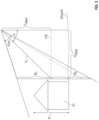
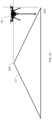
- FIG. 5is an exemplary diagram illustrating lateral and vertical offset of an unmanned aircraft in relation to a structure in accordance with the present disclosure.
- FIG. 6is an exemplary screen shot of a nadir image of the structure shown in FIG. 4 , the screen shot illustrating an exemplary flight plan for an unmanned aircraft.
- FIG. 7is another exemplary screen shot of nadir image of the structure shown in FIG. 6 , the screen shot illustrating another exemplary flight plan for an unmanned aircraft.
- FIG. 8is an exemplary screen shot of a nadir image of the structure shown in FIG. 4 , the screen shot illustrating a camera path of an unmanned aircraft.
- FIG. 9is an exemplary screen shot of a structure report displayed on a display unit of a user terminal.
- FIG. 10is an exemplary screen shot of two oblique images of a structure, each oblique image showing the structure at a distinct time period.
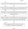
- FIG. 11is a flow chart of another exemplary embodiment of a program logic according to the instant disclosure.
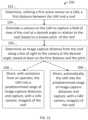
- FIG. 12is a flow chart of yet another exemplary embodiment of a program logic according to the instant disclosure.
- FIG. 13is a flow chart of yet another exemplary embodiment of a program logic according to the instant disclosure.
- FIG. 14is an illustration of portions of a method for navigating an unmanned aircraft using pitch of a roof in accordance with the instant disclosure.
- FIG. 15is an illustration of portions of a method for navigating an unmanned aircraft using pitch of a roof in accordance with the instant disclosure.
- FIG. 16is an exemplary screen shot of a display in a system for navigating an unmanned aircraft using pitch of a roof in accordance with the instant disclosure.
- FIG. 17is an illustration of portions of a method for navigating an unmanned aircraft using pitch of a roof in accordance with the instant disclosure.
- FIG. 18is an exemplary screen shot of a display in a system for navigating an unmanned aircraft using pitch of a roof in accordance with the instant disclosure
- FIG. 19is an illustration of portions of a method for navigating an unmanned aircraft using pitch of a roof in accordance with the instant disclosure.
- FIG. 20is an illustration of portions of a method for navigating an unmanned aircraft using pitch of a roof in accordance with the instant disclosure.
- FIG. 21is an illustration of portions of a method for navigating an unmanned aircraft using pitch of a roof in accordance with the instant disclosure.
- FIG. 22is an illustration of portions of a method for navigating an unmanned aircraft using pitch of a roof in accordance with the instant disclosure.
- FIG. 23is an illustration of portions of a method for navigating an unmanned aircraft using pitch of a roof in accordance with the instant disclosure.
- FIG. 24is an illustration of portions of a method for navigating an unmanned aircraft using pitch of a roof in accordance with the instant disclosure.
- FIG. 25is a diagram of a method for navigating an unmanned aircraft using pitch of a roof in accordance with the instant disclosure.
- FIG. 26is a diagram of a method for navigating an unmanned aircraft using pitch of a roof in accordance with the instant disclosure.
- FIG. 27is an illustration of portions of a method for navigating an unmanned aircraft using pitch of a roof in accordance with the instant disclosure.
- FIG. 28is an exemplary screen shot of a display in a system for navigating an unmanned aircraft using pitch of a roof in accordance with the instant disclosure.
- FIG. 29is an illustration of an exemplary unmanned aircraft in accordance with the instant disclosure.
- FIG. 30is an illustration of an exemplary unmanned aircraft in accordance with the instant disclosure.
- FIG. 31is an illustration of an exemplary unmanned aircraft in accordance with the instant disclosure.
- FIG. 32 Ais an illustration of a perspective view of an exemplary unmanned aircraft in accordance with the instant disclosure.
- FIG. 32 Bis another perspective view of the exemplary unmanned aircraft of FIG. 32 A .
- FIG. 33is an illustration of an exemplary unmanned aircraft in accordance with the instant disclosure.
- FIG. 34 Ais an illustration of an exemplary unmanned aircraft in accordance with the instant disclosure.
- FIG. 34 Bis a side view of the exemplary unmanned aircraft of FIG. 34 A .
- FIG. 34 Cis an end view of the exemplary unmanned aircraft of FIG. 34 A .
- FIG. 35is a diagram of a method for navigating an unmanned aircraft using pitch of a roof in accordance with the instant disclosure.
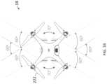
- FIG. 36is a diagram of a method for navigating an unmanned aircraft using pitch of a roof in accordance with the instant disclosure.
- inventive conceptis not limited in its application to the details of construction and the arrangement of the components or steps or methodologies set forth in the following description or illustrated in the drawings.
- inventive concept disclosed hereinis capable of other embodiments or of being practiced or carried out in various ways.
- phraseology and terminology employed hereinis for the purpose of description and should not be regarded as limiting in any way.
- network-basedAs used herein, the terms “network-based”, “cloud-based” and any variations thereof, are intended to include the provision of configurable computational resources on demand via interfacing with a computer and/or computer network, with software and/or data at least partially located on the computer and/or computer network, by pooling processing power of two or more networked processors.
- the terms “comprises”, “comprising”, “includes”, “including”, “has”, “having”, or any other variation thereof,are intended to be non-exclusive inclusions.
- a process, method, article, or apparatus that comprises a set of elementsis not limited to only those elements but may include other elements not expressly listed or even inherent to such process, method, article, or apparatus.
- the terms “provide”, “providing”, and variations thereofcomprise displaying or providing for display a webpage (e.g., roofing webpage) to one or more user terminals interfacing with a computer and/or computer network(s) and/or allowing the one or more user terminal(s) to participate, such as by interacting with one or more mechanisms on a webpage (e.g., roofing webpage) by sending and/or receiving signals (e.g., digital, optical, and/or the like) via a computer network interface (e.g., Ethernet port, TCP/IP port, optical port, cable modem, and combinations thereof).
- a usermay be provided with a web page in a web browser, or in a software application, for example.
- structure requestmay comprise a feature of the graphical user interface or a feature of a software application, allowing a user to indicate to a host system that the user wishes to place an order, such as by interfacing with the host system over a computer network and exchanging signals (e.g., digital, optical, and/or the like), with the host system using a network protocol, for example.
- signalse.g., digital, optical, and/or the like
- Such mechanismmay be implemented with computer executable code executed by one or more processors, for example, with a button, a hyperlink, an icon, a clickable symbol, a microphone, and/or combinations thereof, that may be activated by a user terminal interfacing with the at least one processor over a computer network, for example.
- qualifiers like “substantially,” “about,” “approximately,” and combinations and variations thereof,are intended to include not only the exact amount or value that they qualify, but also some slight deviations therefrom, which may be due to manufacturing tolerances, measurement error, wear and tear, stresses exerted on various parts, and combinations thereof, for example.
- any reference to “one embodiment” or “an embodiment”means that a particular element, feature, structure, or characteristic described in connection with the embodiment is included in at least one embodiment.
- the appearance of the phrase “in one embodiment” in various places in the specificationare not necessarily all referring to the same embodiment.
- the unmanned aircraft structure evaluation system 10may comprise one or more host systems 12 interfacing and/or communicating with one or more user terminals 14 via a network 16 .
- the one or more host systems 12may receive identification information relating to a structure 21 (e.g., building) via the user terminals 14 , and/or data indicative of the geographic positions of the structure 21 . Using the identification information and the geographic positioning of the structure 21 , the one or more host systems 12 may generate unmanned aircraft information including one or more of flight path information, camera control information, and/or gimbal control information. The unmanned aircraft information may be used by an unmanned aircraft 18 to capture one or more aerial images 62 (e.g., nadir images and/or oblique images) of the structure 21 . The unmanned aircraft 18 may also be referred to herein as an Unmanned Aerial Vehicle, or UAV.
- UAVUnmanned Aerial Vehicle
- the flight path information, camera control information, and/or gimbal control informationmay be determined automatically and/or semi-automatically by analyzing and using geo-referenced images. In some embodiments, the flight path information, camera control information, and/or gimbal control information may be determined automatically and/or semi-automatically using a combination of sensor information from the unmanned aircraft 18 , data indicative of one or more points on the structure 21 , and/or data indicative of 2D and/or 3D models of the structure 21 . As such, manual manipulation and/or analysis by a user may be minimized and/or eliminated.
- the flight path information, camera control information and/or gimbal control informationmay be determined with the aid of a user who supplies data by interacting with one or more displayed oblique image of the structure 21 and/or otherwise inputs data into one or more of the user terminals 14 .
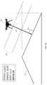
- the structure 21may be a man-made structure, such as a building or infrastructure (e.g., a bridge). In one example shown in FIG. 2 , the structure 21 is a residential building. Alternatively, or additionally, the structure 21 may be a naturally occurring structure, such as a tree, for example.
- the unmanned aircraft 18may be any type of unmanned aerial vehicle that can be controlled by using a flight plan. Flight of the unmanned aircraft 18 may be controlled autonomously as described in further detail herein. In some embodiments, flight may be controlled using a flight plan in combination with piloting by a user located externally to the unmanned aircraft 18 .
- Exemplary unmanned aircraft 18may include the Professional SR100 UAC Camera Drone manufactured and distributed by Cadence Technology located in Singapore.
- Other exemplary unmanned aircraft 18may include the Skydio drone, manufactured and distributed by Skydio, located in Redwood City, California, including multiple cameras having overlapping fields of view that collectively cover a 360 degree field of view around the unmanned aircraft 18 .
- Images from the overlapping fields of viewcan be used as a part of a collision detection and avoidance system that assists the unmanned aircraft 18 in avoiding obstacles near the structure.
- exemplary obstaclesinclude powerlines, trees, antennas, neighboring buildings, birds, other aircraft, or the like.
- the obstacles (and areas without obstacles)can be detected by using aerial triangulation techniques to interpret the images.
- Still other exemplary unmanned aircraftmay include the DJI drones (non-exclusive examples of which include the Phantom 4 Pro v2, the Mavic Pro, and the Mavic 2), manufactured and distributed by DJI, Nanshan District, Shenzhen, China.
- the unmanned aircraft 18may comprise an airframe, a controller, a communications system, a power system, a propulsion system, and an avionics system.
- the unmanned aircraft 18may comprise a navigation system, or the navigation system may be partially or completely in the user terminal(s) 14 and/or the host system 12 and/or elsewhere in the network 16 .
- the unmanned aircraft 18may comprise one or more Electronic Speed Control (ESC).
- the unmanned aircraft 18may comprise one or more power bus.
- the unmanned aircraft 18may comprise one or more speed reduction device.
- the unmanned aircraft 18may comprise one or more actuator.
- the propulsion systemmay include one or more propeller 222 (a hub with a number of rotating air foils or blades) and/or one or more jet.
- the avionics systemmay include mechanical and electronic flight control mechanisms such as motor(s), servo(s), fuel control switches, etc., associated with various flight operations.
- any type of aircraft airframemay be used as the basis of the airframe of the unmanned aircraft 18 .
- types of unmanned aircraft 18 having different airframesinclude a fixed-wing unmanned aircraft 18 having a front or rear propeller, a fixed-wing unmanned aircraft 18 having multiple wing propellers, a helicopter type unmanned aircraft 18 , a multi-rotor unmanned aircraft 18 , a tilt-rotor unmanned aircraft 18 , a jet-type unmanned aircraft 18 , and a blimp-type unmanned aircraft 18 .
- the airframe of the unmanned aircraft 18may have one or more control surfaces such as elevators, rudders, flaps, slats, and/or ailerons.
- the unmanned aircraft 18may include one or more computer processor 27 capable of executing instructions and one or more non-transitory memory 29 .
- the one or more processor 27may be capable of reading and/or executing processor executable code and/or of creating, manipulating, altering, and/or storing computer data structures into the one or more non-transitory memory 29 (which may also be referred to herein as non-transitory computer readable medium 29 ).
- the one or more computer processor 27may be part of the controller.
- the unmanned aircraft 18may include one or more sensors 17 .
- the sensors 17may include one or more location sensors configured to determine distance to, presence of, and/or shape of one or more point on and/or surface of an object. Nonexclusive examples of such objects include the structure 21 and/or obstacles in the path of the unmanned aircraft 18 .
- the sensors 17may include infrared sensors, radar devices, LiDAR devices, and/or sonar devices.
- the sensors 17may include active sensors, passive sensors or a combination of active and passive sensors.
- a passive sensoris an instrument designed to receive, capture, and/or to measure emissions, reflections, or refractions, such as light.
- a passive sensormay measure reflected light, such as reflected sunlight emitted from the sun.
- An active sensoris an instrument used for measuring signals transmitted by the sensor that were reflected, refracted, or scattered from one or more object.
- An active sensorhas its own source of light or illumination. In particular, an active sensor actively sends a wave/signal and measures that backscatter reflected back to the active sensor.
- the one or more sensors 17is one sensor 17 configured to obtain multiple distance readings at known angles 39 from one another.
- One example of such a sensor 17is described in U.S. Pat. No. 9,244,272, titled “Lidar System Producing Multiple Scan Paths and Method of Making and Using Same”, issued on Jan. 26, 2016, the entire contents of which are hereby incorporated herein.
- the one or more sensors 17are two or more sensors 17 positioned at a known angle 39 from one another (see, for example, FIG. 19 ).
- a first sensor 17 amay be substantially forward facing in relation to the direction of travel of the unmanned aircraft 18 and a second sensor 17 b may downward facing in relation to the unmanned aircraft 18 (see, for example, FIG. 19 ).
- a line along a first distance 41 determined by the first sensor 17may be approximately ninety degrees from a line along a second distance 43 determined by the second sensor 17 (see, for example, FIGS. 19 and 26 ).
- the known angle 39 between the line along the first distance 41 determined by the first sensor 17 and the line along the second distance determined by the second sensor 17may be less than or more than ninety degrees (see, for example, FIGS. 25 - 26 ).
- sensor readings from the one or more sensors 17 of the unmanned aircraft 18may be accessed via a component library that allows connection to a specific unmanned aircraft 18 while connected to its physical remote control by a communication cable (or by wireless transmission), and to read its current flight state, as well as the values of the various sensors (when present) of the aircraft itself.
- a component libraryis the software developer's kit (“SDK”) from DJI entitled DJI Mobile SDK for iOS.
- a particular SDK from a manufacturer of unmanned aircraft 18allows a software application developer to connect to the unmanned aircraft 18 (such as the DJI Phantom or Mavic models), read its current status, get readings from its sensors 17 , and create missions that the unmanned aircraft 18 will perform on its own according to a specific set of instructions.
- the SDKcan obtain readings from multiple models of unmanned aircrafts 18 , and not all unmanned aircraft 18 have the same set of distance sensors 17 (some unmanned aircraft 18 do not have distance sensors), a software application creator must determine which sensors 17 can be read, as well as determine how many sensors 17 (and which sensors 17 ) will return the expected results for its software application.
- FIGS. 29 - 34illustrate non-exclusive examples of unmanned aircraft 18 having one or more sensor 17 .
- the one or more sensor 17may include ultrasonic distance sensors and/or infrared sensors pointing down at the ground in relation to the unmanned aircraft 18 at a neutral position (see, for example, FIGS. 29 - 30 ).
- the ultrasonic distance sensors 17operate by sending high frequency signals (higher, at least, than the range for human hearing) in a cone. The width of the cone varies, though may be about seventy degrees wide. Any obstacle/object that reflects those signals will send them back to the ultrasonic distance sensors 17 .
- the ultrasonic distance sensors 17may have a precision of ten centimeters, and may produce distance calculations that are valid up to five meters.
- Some unmanned aircraft 17may use infrared sensors 17 (see FIG. 30 ), but may report the infrared sensor readings as if they were ultrasonic sensor readings.
- the SDKmay return the output of ultrasonic (or infrared) distance sensors 17 in a single point (for example, the “ultrasonicHeightInMeters” property in DJIFlightControllerState). This value that is returned may be used as the downward distance from the sensor 17 to the structure 21 .
- the unmanned aircraft 18may include one or more cameras 19 configured to provide aerial images 62 .
- the camera 19may be mounted on a gimbal 220 support (e.g., three-axis gimbal).
- the unmanned aircraft 18may include one or more “Vision” sensors 17 , which may combine ultrasonic/infrared sensors 17 and cameras 19 pointing in several directions from the unmanned aircraft 18 , to allow the unmanned aircraft 18 to detect more precisely any obstacles/objects in those directions (see FIGS. 31 - 32 ). From the perspective of the SDK, the sensors 17 are able to return the distance to the nearest obstacle/object that they detect. The sensors 17 can point forward (following the direction of the main camera 19 in the unmanned aircraft 18 ), backwards, and/or laterally. Some unmanned aircraft 18 may have one or more sensors 17 pointing upward and downward. The sensors 17 may have a specific range of operation (measured in degrees, where the origin point is the sensor 17 itself), as exemplified in the exemplary unmanned aircraft 18 depicted in FIGS. 33 - 34 .
- the unmanned aircraft 18may include one or more global positioning system (GPS) receivers, one or more inertial navigation units (INU), one or more clocks, one or more gyroscopes, one or more compasses, one or more altimeters, and/or the like so that the position and orientation of the unmanned aircraft 18 at specific instances of time can be monitored, recorded, and/or stored with and/or correlated with particular images 62 .
- GPSglobal positioning system
- INUinertial navigation units
- clocksone or more gyroscopes
- compassesone or more altimeters, and/or the like
- the one or more cameras 19may be capable of capturing images 62 photographically and/or electronically as well as recording the time at which particular images 62 are captured. In one embodiment, this can be accomplished by sending a signal to a processor (that receives time signals from the GPS) each time an image 62 is captured.
- the one or more cameras 19may include, but are not limited to, conventional cameras, digital cameras, digital sensors, charge-coupled devices, and/or the like. In some embodiments, one or more cameras 19 may be ultra-high resolution cameras.
- the camera 19may capture digital images and/or the captured images 62 may be transformed into digital images.
- the digital imagescomprise pixels.
- the one or more cameras 19may include known or determinable characteristics including, but not limited to, focal length, sensor size, aspect ratio, radial and other distortion terms, principal point offset, pixel pitch, alignment, and/or the like.
- the unmanned aircraft 18may communicate with the one or more user terminals 14 .
- the one or more user terminals 14may be implemented as a personal computer, a handheld computer, a smart phone, a wearable computer, network-capable TV set, TV set-top box, a tablet, an e-book reader, a laptop computer, a desktop computer, a network-capable handheld device, a video game console, a server, a digital video recorder, a DVD-player, a Blu-Ray player and combinations thereof, for example.
- the user terminal 14may comprise an input unit 20 , a display unit 22 , a processor 23 capable of interfacing with the network 16 , one or more non-transitory memory 25 (which may also be referred to herein as non-transitory computer readable medium 25 ), processor executable code, and a web browser capable of accessing a website and/or communicating information and/or data over a network, such as the network 16 .
- the one or more user terminals 14may comprise one or more non-transitory memories 25 having processor executable code and/or software applications, for example.
- the input unit 20may be capable of receiving information input from a user and/or other processor(s), and transmitting such information to the user terminal 14 and/or to the one or more host systems 12 .
- the input unit 20may be implemented as a keyboard, a touchscreen, a mouse, a trackball, a microphone, a fingerprint reader, an infrared port, a slide-out keyboard, a flip-out keyboard, a cell phone, a PDA, a video game controller, a remote control, a fax machine, a network interface, and combinations thereof, for example.
- the user terminal 14is loaded with flight management software for controlling the unmanned aircraft 18 .
- the display unit 22may output information in a form perceivable by a user and/or other processor(s).
- the display unit 22may be a server, a computer monitor, a screen, a touchscreen, a speaker, a website, a TV set, a smart phone, a PDA, a cell phone, a fax machine, a printer, a laptop computer, a wearable display, and/or combinations thereof.
- the input unit 20 and the display unit 22may be implemented as a single device, such as, for example, a touchscreen or a tablet.
- the term useris not limited to a human being, and may comprise a computer, a server, a website, a processor, a network interface, a human, a user terminal, a virtual computer, and combinations thereof, for example.
- the system 10may include one or more host systems 12 .
- the one or more host systems 12may be partially or completely network-based or cloud based, and not necessarily located in a single physical location.
- Each of the host systems 12may further be capable of interfacing and/or communicating with the one or more user terminals 14 via the network 16 , such as by exchanging signals (e.g., digital, optical, and/or the like) via one or more ports (e.g., physical or virtual) using a network protocol, for example.
- each host system 12may be capable of interfacing and/or communicating with other host systems directly and/or via the network 16 , such as by exchanging signals (e.g., digital, optical, and/or the like) via one or more ports.
- system 10may include two host systems 12 with a first host system controlled by a first company and a second host system controlled by a second company distinct from the first company.
- the one or more host systems 12may comprise one or more processors 24 working together, or independently to, execute processor executable code, one or more memories 26 capable of storing processor executable code, one or more input devices 28 , and one or more output devices 30 .
- Each element of the one or more host systems 12may be partially or completely network-based or cloud-based, and not necessarily located in a single physical location. Additionally, in embodiments having multiple host systems 12 , each host system may directly communicate with additional host systems and/or third-party systems via the network 16 .
- the one or more processors 24may be implemented as a single or plurality of processors 24 working together, or independently to execute the logic as described herein. Exemplary embodiments of the one or more processors 24 include a digital signal processor (DSP), a central processing unit (CPU), a field programmable gate array (FPGA), a microprocessor, a multi-core processor, and/or combinations thereof.
- DSPdigital signal processor
- CPUcentral processing unit
- FPGAfield programmable gate array
- microprocessora multi-core processor, and/or combinations thereof.
- the one or more processors 24may be capable of communicating with the one or more memories 26 via a path (e.g., data bus).
- the one or more processors 24may be capable of communicating with the input devices 28 and the output devices 30 .
- the one or more processors 24may be further capable of interfacing and/or communicating with the one or more user terminals 14 and/or unmanned aircraft 18 via the network 16 .
- the one or more processors 24may be capable of communicating via the network 16 by exchanging signals (e.g., digital, optical, and/or the like) via one or more physical or virtual ports (i.e., communication ports) using a network protocol.
- signalse.g., digital, optical, and/or the like
- the one or more processors 24may be located remotely from one another, located in the same location, or comprising a unitary multi-core processor (not shown).
- the one or more processors 24may be capable of reading and/or executing processor executable code and/or of creating, manipulating, altering, and/or storing computer data structures into one or more memories 26 , which may also be referred to herein as non-transitory computer readable medium 26 .
- the one or more memories 26may be capable of storing processor executable code. Additionally, the one or more memories 26 may be implemented as a conventional non-transitory memory, such as, for example, random access memory (RAM), a CD-ROM, a hard drive, a solid state drive, a flash drive, a memory card, a DVD-ROM, a floppy disk, an optical drive, and/or combinations thereof. It is to be understood that while one or more memories 26 may be located in the same physical location as the host system 12 , the one or more memories 26 may be located remotely from the host system 12 , and may communicate with the one or more processor 24 via the network 16 .
- RAMrandom access memory
- a first memorymay be located in the same physical location as the host system 12 , and additional memories 26 may be located in a remote physical location from the host system 12 .
- the physical location(s) of the one or more memories 26may be varied.
- one or more memories 26may be implemented as a “cloud memory” (i.e., one or more memory 26 may be partially or completely based on or accessed using the network 16 ).
- the one or more input devices 28may transmit data to the processors 24 , and may be implemented as a keyboard, a mouse, a touchscreen, a camera, a cellular phone, a tablet, a smart phone, a PDA, a microphone, a network adapter, a wearable computer and/or combinations thereof.
- the input devices 28may be located in the same physical location as the host system 12 , or may be remotely located and/or partially or completely network-based.
- the one or more output devices 30may transmit information from the processor 24 to a user, such that the information may be perceived by the user.
- the output devices 30may be implemented as a server, a computer monitor, a cell phone, a tablet, a speaker, a website, a PDA, a fax, a printer, a projector, a laptop monitor, a wearable display and/or combinations thereof.
- the output device 30may be physically co-located with the host system 12 , or may be located remotely from the host system 12 , and may be partially or completely network based (e.g., website).
- the term “user”is not limited to a human, and may comprise a human, a computer, a host system, a smart phone, a tablet, and/or combinations thereof, for example.
- the network 16may permit bi-directional communication of information and/or data between the one or more host systems 12 , the user terminals 14 and/or the unmanned aircraft 18 .
- the network 16may interface with the one or more host systems 12 , the user terminals 14 , and the unmanned aircraft 18 in a variety of ways.
- the one or more host systems 12 , the user terminals 14 , and/or the unmanned aircraft 18may communicate via a communication port.
- the network 16may interface by optical and/or electronic interfaces, and/or may use a plurality of network topographies and/or protocols including, but not limited to, Ethernet, TCP/IP, circuit switched paths, and/or combinations thereof.
- the network 16may be implemented as the World Wide Web (or Internet), a local area network (LAN), a wide area network (WAN), a metropolitan network, a wireless network, a cellular network, a GSM-network, a CDMA network, a 3G network, a 4G network, a satellite network, a radio network, an optical network, a cable network, a public switched telephone network, an Ethernet network, and/or combinations thereof.
- the network 16may use a variety of network protocols to permit bi-directional interface and/or communication of data and/or information between the one or more host systems 12 , the one or more user terminals 14 and/or the unmanned aircraft 18 .
- the one or more host systems 12 , the user terminals 14 , and/or the unmanned aircraft 18may communicate by using a non-transitory computer readable medium.
- data obtained from the user terminal 14may be stored on a USB flash drive.
- the USB flash drivemay be transferred to and received by the unmanned aircraft 18 thereby communicating information, such as the unmanned aircraft information including flight path information, camera control information, and/or gimbal control information from the user terminal 14 to the unmanned aircraft 18 .
- the USB flash drivemay also be used to transfer images 62 captured by the camera 19 , position, orientation and time date to the user terminal(s) 14 .
- the one or more memories 26may store processor executable code and/or information comprising a structure location database 32 , one or more images databases 34 , one or more structure shape database 35 , and program logic 36 .
- the processor executable codemay be stored as a data structure, such as a database and/or a data table, for example.
- one or more memories 25 of the user terminal 14 and/or of the unmanned aircraft 18may include a structure database 32 , one or more image databases 34 , one or more structure shape database 35 , and program logic 36 as described in further detail herein.
- the structure location database 32 , the one or more image databases 34 , and/or the one or more structure shape database 35may be combined.
- the structure location database 32may include geographical information (e.g., location, GIS data) about the structure 21 .
- the structure location database 32may store identification information about the structure including, but not limited to, address, geographic location, latitude/longitude, and/or the like.
- the one or more memories 26may include one or more image databases 34 .
- the one or more image databases 34may store digital imagery and/or digital geo-referenced imagery. Such imagery may be represented by a single pixel map, and/or by a series of tiled pixel maps that when aggregated recreate the image pixel map. Geo-referenced imagery may include nadir, ortho-rectified, and/or oblique geo-referenced images.
- the one or more processors 24may provide the images via the image database 34 to users at the one or more user terminals 14 .
- one or more image databases 34may be included within the user terminals 14 .
- Geo-referenced imagerymay have geographic location information for the pixels of the images 62 .
- the images 62may be processed as described in U.S. Pat. No. 7,424,133, issued Sep. 9, 2008, titled “Method and Apparatus for Capturing, Geolocating and Measuring Oblique Images;” and/or U.S. Patent Publication US20150221079A1, published Aug. 6, 2015, titled “Augmented Three Dimensional Point Collection of Vertical Structures;” all of which are hereby incorporated by reference in their entirety herein.
- the geographic location informationmay include geographic coordinates for the ground as well as structures and objects located above the ground in the image.
- the geographic location information for the pixels of the imagemay be a part of the metadata associated with the image.
- Georeferencing the imagesmay be based at least in part on one or more known ground points and/or surface points.
- known ground points and/or surface pointsinclude digital elevation models (DEMs), point clouds, three-dimensional models, individually plotted/mapped points, and tessellated ground planes.
- the imagesmay be georeferenced based at least in part on searching for and locating one or more surface model or point cloud having locations within a predetermined proximity of the location of the unmanned aircraft 18 and/or in the direction of orientation of the unmanned aircraft 18 . In one embodiment, the images may be georeferenced based at least in part on searching for and locating one or more ground point or ground plane having ground locations within a predetermined proximity of the unmanned aircraft 18 .
- the images 62may be geo-located. Geolocating the image 62 may comprise associating the image 62 with a location or structure in a location.
- Geolocation of the image 62is for images depicting objects above the ground without depicting the ground, or without ground location information, or without access to surface location information for the objects depicted.
- an image 62may depict a chimney on a roof without depicting the ground location. Metadata can be used to associate the image with a particular location or structure.
- Metadatacan be used that is associated with the one or more image capture device at the time the aerial images 62 were captured, such as latitude and longitude of the one or more image capture device and/or one or more of altitude, orientation, attitude, and bearing of the one or more image capture device.
- the metadatacan be correlated to the location or structure thereby associating the image 62 with the location or structure 21 .
- the one or more structure shape database 35may include geo-spatial and/or relational information about the structure 21 .
- Non-exclusive examples of such information within the structure shape database 35include two-dimensional model information, three-dimensional model information, point cloud data, data points indicative of a geometric configuration of the structure 21 , feature data (regarding portions of the structure 21 ), relational data (for example, the relationship between points of the structure 21 ), and combinations thereof.
- the one or more memories 26may further store processor executable code and/or instructions, which may comprise the program logic 36 .
- the program logic 36may comprise processor executable instructions and/or code, which when executed by the processor 24 , may cause the processor 24 to execute image display and analysis software to generate, maintain, provide, and/or host a website providing one or more structure evaluation requests, for example.
- the program logic 36may further cause the processor 24 to collect identification information about the structure 21 (e.g., address), allow one or more users to validate a location of the structure, obtain geographical positions of the structure, and the like, as described herein.
- Program logic 36may comprise executable code, which when executed by the one or more processors 24 may cause the one or more processors 24 to execute one or more of the following steps.
- the one or more host systems 12may receive identification information of the structure from the user terminal 14 .
- the one or more host systems 12may receive the address of the structure, geographic location of the structure (e.g., X, Y, Z coordinates, latitude/longitude coordinates), a location of the user terminal 14 determined by a Geographic Position System (GPS), and/or the like.
- GPSGeographic Position System
- the usermay validate the location of the structure 21 .
- One or more processor 24may provide one or more images 62 via the image database 34 to the display unit 22 of the user terminal 14 .
- FIG. 4illustrates an exemplary screen shot 60 of an oblique image 62 of the structure 21 that may be displayed on the display unit 22 of the user terminal 14 , shown in the block diagram of FIG. 1 .
- the one or more images 62may be geo-referenced images illustrating portions or all of the structure 21 . Referring to FIGS.
- the program logic 36may cause the processor 24 to provide users the one or more geo-referenced images 62 (e.g., via the display unit 22 ), and allow the user to validate the location of the structure 21 (e.g., via the input unit 20 ).
- the usermay be able to use a drag-and-drop element provided by the program logic 36 via user terminal 14 to select the structure 21 within the one or more geo-referenced images 62 .
- Selection of the structure 21 within the one or more geo-referenced images 62may provide one or more validated images and a validated location of the structure 21 .
- the program logic of the user terminal 14may provide users the one or more geo-referenced images 62 to allow for validation of the location of the structure 21 .
- validation of the geo-referenced images 62may be provided by one or more additional host systems via the one or more processors 24 in lieu of, or in combination with host system 12 .
- the host system 12may direct the user to a second host system wherein one or more processors of the second host system may provide geo-referenced images 62 from image database to the user for validation of one or more structures 21 .
- the geographic locationmay include coordinates, and validation of the geographic location may be provided by the user by altering one or more coordinates of the geographic location. Users may alter the one or more coordinates by methods including, but not limited to, manual manipulation, drag-and-drop elements, and the like.
- location of the structure 21may be automatically determined by location of the user terminal 14 .
- a usermay be physically present at the structure 21 , and the user may be holding the user terminal 14 which determines its location using any suitable technology, such as a Global Positioning System or location triangulation using wireless signals.
- any suitable technologysuch as a Global Positioning System or location triangulation using wireless signals.
- location coordinates of the user terminal 14the location of the structure 21 may be determined.
- a footprint and/or a three-dimensional model of the structure 21may be determined.
- the footprint and/or three-dimensional modelmay provide one or more two-dimensional boundaries (e.g., sides) and/or outlines of the structure 21 .
- the footprint and/or the three-dimensional model of the structure 21may be determined using systems and methods including, but not limited to, those described in U.S. Pat. No. 8,145,578, titled “Aerial Roof Estimation System and Method”; U.S. Pat. No. 8,170,840, titled “Pitch Determination Systems and Methods for Aerial Roof Estimation”; U.S. Pat. No.
- the footprint and/or the three-dimensional model of the structure 21may be provided to the user via the display unit 22 .
- the footprint and/or the three-dimensional model of the structure 21may be displayed as a layer on one or more images (e.g., nadir image) via the display unit 22 .
- the one or more processors 24may provide, via the display unit 22 , one or more websites to the user for evaluation of multiple oblique images to provide the footprint and/or the three-dimensional model of the structure 21 .
- the user and/or the processors 24may identify edges of the structure 21 .
- Two-dimensional and/or three-dimensional information regarding the edgese.g., position, orientation, and/or length
- line segmentsmay be determined with multiple line segments forming at least a portion of the footprint and/or the three-dimensional model of the structure 21 .
- data indicative of geographic positions pertaining to the footprint of the structure 21 and/or structure height informationmay be obtained.
- the height of structure 21 above the groundmay be determined.
- the height of the structure 21 above the groundmay aid in determining altitude for the flight plan of the unmanned aircraft 18 as discussed in further detail herein.
- more than one heightmay be used.
- Altitude for the flight path of the unmanned aircraft 18may vary based on the differing heights of the structure 21 or objects in close proximity to the structure 21 .
- Measurements of the geographic positions of the structure 21may include techniques as described in U.S. Pat. No. 7,424,133, which is hereby incorporated herein by reference in its entirety.
- the term “vertical structures”, as used hereinincludes structures that have at least one portion of one surface that is not fully horizontal.
- “vertical structures” as described hereinincludes structures that are fully vertical and structures that are not fully vertical, such as structures that are pitched at an angle and/or that drop into the ground.
- the side of a structureis not limited to only one or more walls of the structure 21 , but may include all visible parts of the structure 21 from one viewpoint. For instance, when the present disclosure is discussing a structure 21 , such as a house, a “side” or “vertical side” includes the wall of the house and the roof above the wall up to the highest point on the house.
- the usermay optionally give additional details regarding geographic positions pertaining to the structure 21 .
- the structure 21is a roof of a building
- the usermay include identification of areas such as eaves, drip edges, ridges, and/or the like.
- the usermay manually give values for pitch, distance, angle, and/or the like.
- the one or more processors 24may evaluate imagery and/or other data and determine areas including eaves, drip edges, ridges and/or the like without manual input of the user.
- unmanned aircraft informationmay be generated by the one or more host systems 12 and/or the user terminal 14 .
- the unmanned aircraft informationmay include flight path information, camera control information, and/or gimbal control information.
- Flight path informationmay be configured to direct the unmanned aircraft 18 to fly a flight path in relation to the structure 21 .
- the flight pathmay be configured to allow the unmanned aircraft 18 to take sensor readings and/or aerial images of the structure 21 .
- a flight pathmay be displayed to the user on one or more images (e.g., nadir, oblique) via the display unit 22 .
- FIG. 6illustrates an exemplary screen shot 66 of a nadir image 68 showing a flight path 70 about the structure 21 .
- the flight path 70may be displayed as a layer overlapping the nadir image 68 of the structure 21 on the display unit 22 of FIG. 1 .
- the flight path informationdirects the unmanned aircraft 18 in three dimensions.
- the flight path informationmay be determined such that the flight path 70 around the structure 21 is laterally and/or vertically offset from the geographic positions of the outline of the structure 21 .
- lateral offset L OFFSET and vertical offset V OFFSETmay be dependent upon the height H of the structure 21 , orientation of the camera relative to the unmanned aircraft 18 , and characteristics of the camera 19 .
- the field of view (FOV) of the camera 19may be positioned such that a center C 1 is at one half the height H of the structure 21 , for example.
- one or more buffer regions Bmay be added to the FOV. Buffer regions B may increase the angle of the FOV by a percentage. For example, buffer regions B 1 and B 2 illustrated in FIG. 5 may increase the angle of the FOV by 20-50%.
- a predetermined angle ⁇within a range of approximately 25 degrees to approximately 75 degrees may be set.
- the lateral offset L OFFSET and the vertical offset V OFFSET of the camera 19 relative to the structure 21may be determined using trigonometric principles, for example.
- the flight path informationmay optionally direct the roll, pitch and yaw of the unmanned aircraft 18 .
- some versions of the unmanned aircraft 18may not have a multi-axis gimbal and as such, can be directed to aim the camera 19 by changing the yaw, pitch or roll of the unmanned aircraft 18 .
- the current yaw, pitch and roll of the unmanned aircraft 18may be measured using a position and orientation system that is a part of the unmanned aircraft 18 .
- the position and orientation systemmay be implemented using microelectromechanical based accelerometers and/or microelectromechanical based pyrometers.
- the flight path 70may be determined such that interference with outside elements (e.g., trees and telephone wires) may be minimized.
- FIG. 7illustrates a variation of the flight path 70 determined in FIG. 4 wherein the flight path 70 a of FIG. 7 minimizes interference by following the outline of the structure 21 .
- a ground confidence mapas described in U.S. Pat. No. 8,588,547, which disclosure is hereby incorporated herein by reference, could be used to identify objects for which there is a high degree of confidence that the object lies elevated off of the ground. Auto-correlation and auto-aerial triangulation methods could then be used to determine the heights of these potential obstructions. If the flight path 70 would go through one of these obstructions, the flight path 70 may be flagged and the algorithm may then attempt to find the best solution for getting past the obstructions. For example, the flight path 70 may be altered such that the unmanned aircraft 18 may fly closer to the structure 21 as shown in FIG. 7 , which might necessitate additional passes due to a finer resolution of images taken at those locations and therefore smaller path width.
- the flight path 70may be altered such that the unmanned aircraft 18 may fly over the obstruction and aim the camera 19 at a steeper oblique angle, which again may require an adjustment to the flight path 70 to ensure full coverage.
- a system operatormay validate the corrective route chosen and alter it as necessary.
- the unmanned aircraft 18may also incorporate a collision detection and avoidance system in some embodiments.
- the collision detection and avoidance systemmay be imaging based and/or sensor based.
- the software guiding the unmanned aircraft 18may first attempt to move closer to the structure 21 along the path from the Flight Path 70 to a Target Path.
- the collision detection and avoidance systemmay steer the unmanned aircraft 18 back to its original point of collision detection and/or may attempt to fly above the obstacle.
- the suitable threshold of movementmay be set at approximately 10% of the distance between the unmanned aircraft 18 and the structure 21 .
- the thresholdmay be 10% of 104′, that is, 10.4′, so that an approximately 20% overlap still ensures complete coverage of images/scans of the structure 21 .
- the software controlling the unmanned aircraft 18keeps the camera 19 aimed at the Target Path, flying the unmanned aircraft 18 higher may still allow capture by the camera 19 of images of desired portions of the structure 21 ; but the oblique down-look angle may change and the resolution of the images taken may become coarser.
- an operatormay intervene to negotiate the unmanned aircraft 18 around the obstacle.
- the software running on a processor 27 of the unmanned aircraft 18may transmit a signal to the operator for example, in the form of an audible alarm, and allow the operator to steer the unmanned aircraft 18 around the obstacle.
- the camera control informationmay be loaded into the software running on the processor 27 of the unmanned aircraft 18 to control actuation of the camera 19 of the unmanned aircraft 18 .
- the camera control informationmay direct the camera 19 to capture images (e.g., oblique images) at one or more predefined geographic locations 74 (which are referred to herein below as Flight Capture Points), as illustrated in screen shot 72 of FIG. 8 .
- the camera control informationmay direct the camera 19 to capture images on a schedule (e.g., periodic, random).
- the camera control informationmay control camera parameters including, but not limited to zoom, focal length, exposure control and/or the like.
- the camera(s) 19may be triggered to capture images.
- the Flight Capture Pointsmay not just be points, but may be vertical planes that are perpendicular to the Flight Path 70 and that pass through the Flight Capture Points.
- the software controlling the unmanned aircraft 18may cause the camera 19 to fire to capture image(s).
- Gimbal control informationmay be loaded into the software running on the processor 27 of the unmanned aircraft 18 to control the direction of the camera 19 relative to the structure 21 .
- the gimbal control informationmay control the orientation of the camera 19 in three dimensions such that during capture of an image, the camera 19 is aligned with a pre-determined location on the structure 21 that may be referred to herein as Target Capture Points.
- the unmanned aircraft informationmay be stored on one or more non-transitory computer readable medium of the host system 12 and/or user terminal 14 .
- the host system 12may determine the unmanned aircraft information, communicate the unmanned aircraft information to the user terminal 14 via the network 16 , such that the unmanned aircraft information may be stored on one or more non-transitory computer readable medium.
- the user terminal 14may determine the unmanned aircraft information and store the unmanned aircraft information on one or more non-transitory computer readable medium.
- the one or more non-transitory computer readable mediummay include a USB flash drive or other similar data storage device.
- the unmanned aircraft informationmay be loaded onto the unmanned aircraft 18 .
- the unmanned aircraft informationmay then be loaded onto the unmanned aircraft 18 via transfer of the non-transitory computer readable medium (e.g., USB flash drive) or wirelessly transmitted from the user terminal 14 .
- the unmanned aircraft informationmay be loaded and/or stored onto the unmanned aircraft 18 by any communication, including communication via the network 16 .
- the unmanned aircraft 18may use the unmanned aircraft information to capture one or more images of the structure 21 , such as oblique images. Generally, the unmanned aircraft 18 may follow the flight path 70 within the unmanned aircraft information obtaining one or more oblique images 62 as set out within the camera control information and gimbal control information. In some embodiments, a user may manually manipulate the flight path 70 of the unmanned aircraft information during flight of the unmanned aircraft 18 . For example, the user may request the unmanned aircraft 18 to add an additional flight path 70 or repeat the same flight path 70 to obtain additional images 62 .
- the one or more processors 24may receive one or more images 62 , such as oblique images, captured by the unmanned aircraft 18 .
- the flight path information, camera control information, and gimbal control informationmay direct the unmanned aircraft 18 to capture one or more oblique images 62 at predetermined locations and times as described herein.
- the one or more oblique images 62may be communicated to the one or more processors 24 via the network and/or stored one or more non-transitory computer readable medium.
- the one or more oblique images 62may be stored in one or more image database 34 .
- the one or more oblique images 62may be communicated to the user terminal 14 , and the user terminal 14 may communicate the images 62 to the one or more processors 24 .
- the one or more processors 24may generate a structure report.
- the program logic 36may provide for one or more user terminals 14 interfacing with the processor 24 over the network 16 to provide one or more structure report website pages allowing users to view the structure report.
- FIG. 9illustrates an exemplary screen shot 76 of a structure report 78 on the display unit 22 of a user terminal 14 .
- One or more images 62 obtained from the camera 19 of the unmanned aircraft 18may be used for evaluation of the structure 21 for the structure report 78 .
- the images 62 obtained from the camera 19may be used in an insurance evaluation (e.g., flood damage, hail damage, tornado damage).
- One or more images 62 obtained from the cameramay be provided in the structure report 78 .
- the structure report 78 in FIG. 9includes an image data set 82 .
- the image data set 82may include nadir and/or oblique images 62 of the structure 21 .
- the image data set 82may include one or more images 62 of objects of interest on and/or within the structure 21 .
- the structure report 78details damage to a roof of the structure 21
- one or more images 62 of damage to the roofmay be included within the image data set 82 .
- third party images of the structure 21may be included within the structure report 78 .
- Structural detailsmay be provided in the structure report 78 within a structure data set 84 as illustrated in FIG. 9 .
- the structure data set 84may include information related to structure 21 including, but not limited to, area of the structure 21 (e.g., square feet), roof details (e.g., pitch, ridge length, valley length, eave length, rake length), height of the structure 21 , and/or the like. Additionally, the structure data set 84 may include order information for the structure report 78 .
- the structure data set 84may include information regarding the time an order for the structure report 78 was placed, the time the order for the structure report 78 was completed, the delivery mechanism for the structure report 78 , the price of the order for the structure report 78 , and/or the like, for example.
- the location of the camera 19 relative to the structure 21 for images capturedmay also be known.
- the X, Y, Z locatione.g., latitude, longitude, and altitude
- the informationmay be used to further evaluate objects on and/or within the structure 21 .
- images 62 captured by the unmanned aircraft 18may be used to generate a two or three-dimensional model of the structure 21 .
- some embodiments of the unmanned aircraft structure evaluation system 10may be used as follows.
- an insurance adjustor or other field operatormay arrive at the structure 21 to assess the structure 21 for damage or for underwriting.
- the operatormay utilize an online application on a portable networked computer device (e.g., user terminal 14 ), such as a tablet, smart phone, or laptop, and select the property and structure 21 .
- a portable networked computer devicee.g., user terminal 14
- user terminal 14such as a tablet, smart phone, or laptop
- This selectionmay be done with identification information, for example, with a GPS determining the current location of the operator, through entering a street address into the search bar, through entering the geographic location into the user terminal 14 , through scrolling on a map or aerial image displayed on the user terminal 14 of the current location, or through a preselected target property made by virtually any method that results in finding the property and storing it for later retrieval.
- an image or three-dimensional model for that property and structure 21may be displayed on the display unit 22 of the user terminal 14 .
- the imagemay be an oblique image, and/or a street side image, which may provide more information to the operator for property verification than traditional orthogonal images, as traditional orthogonal images do not include any portion of the side of the image.
- a 3D model(which may be textured with an oblique or street side image) may be used. The operator may verify that the property and structure 21 on the display unit 22 matches the property and structure 21 to be evaluated, to ensure that the operator generates the proper report.
- the operatormay then select the structure 21 (for example, by clicking on the structure 21 depicted in the image) and may request a flight plan 70 for that structure 21 .
- Softwarerunning on either or both of the user terminal 14 and the host system 12 may then isolate the structure 21 and generate an outline as described above.
- the softwaremay also cause the user terminal 14 system to determine the height (“H”) of the structure 21 , either by using an automated method, or by having the operator use a height tool on the oblique image, such as through the method described in U.S. Pat. No. 7,424,133.
- This height Hmay then be used to automatically determine the proper flying height, lateral offset L OFFSET , and vertical offset V OFFSET offset for the flight path 70 for the unmanned aircraft 18 (which may be an unmanned aerial system).
- the height Hmay also be used to aim the steerable camera 19 carried by the unmanned aircraft 18 .
- a “Target Path”may be generated that follows the path of the perimeter of the structure 21 and that is at a height over ground such that a center C 1 of the field of view may be located at one-half the height of the structure 21 as illustrated in FIG. 5 .
- the Target Pathwould be generated such that the center C 1 of the field of view may be at 14′ height over ground.
- the height over grounddoes not have to place the center C 1 of the field of view to be one-half the height of the structure 21 and may vary.
- Characteristics of the camera 19may be used, such as, for example, the desired effective resolution of the image as well as the overall sensor size of the camera 19 onboard the unmanned aircraft 18 , to determine the maximum vertical swath width that may be captured on a single pass. For instance, if the desired effective image resolution is 1 ⁇ 4′′ GSD, and the sensor has 4,000 pixels in the vertical orientation, then the maximum vertical swath width would be 1,000′′ or 125′.
- a significant buffer Bmay be subtracted out to allow for position and orientation errors when flying, for buffeting due to wind, and for absolute position errors in the reference imagery.
- the size of the buffer Bmay vary, but may be approximately a 20% buffer on all sides of the imagery.
- the maximum vertical swath widthwould be 75′. If the structure 21 has a greater height H than this, then the structure 21 may need to be captured in multiple passes of the unmanned aircraft 18 . If so, using the same example numbers above, the first pass would be captured at 37.5′ above ground, the second at 112.5′ above ground, the third at 187.5′ above ground, and so on until the desired images of the structure 21 are captured.
- the resolutionmay be increased beyond the desired effective image resolution.
- the resolutionmay be switched to 1 ⁇ 8′′, which would yield a maximum swath width of 37.5′, which is more than sufficient to cover the 28′ of structure height while still including the 20% buffer B on all sides.
- the lateral offset L OFFSET and vertical offset V OFFSETmay then be determined.
- the vertical offset V OFFSETmay then be determined by calculating the path length that achieves the determined resolution. For instance, with a 5-micron sensor pitch size and a 50-mm lens, the path length would be 104′.
- the desired imageryis to be captured at an angle ⁇ of 40-degrees (an angle from approximately 40-degrees to approximately 50-degrees down from horizontal is typically optimal for oblique aerial imagery), then that translates to a lateral offset L OFFSET of 79.6′ stand-off distance (cosine of 40 ⁇ 104′) and a vertical offset V OFFSET of 66.8′ vertical height adjustment (sine of 40 ⁇ 104′).
- the pathwould now be grown by the requisite lateral offset L OFFSET and vertical offset V OFFSET distance using standard geometry or morphological operators to create the Flight Path 70 .
- the Target Pathwere a perfect circle, the radius would be extended by the 79.6′ lateral offset L OFFSET distance. If the target path were a rectangle, each side would be extended outward by the 79.6′ lateral offset L OFFSET distance.
- the flying altitude for the Flight Path 70may be determined by adding the vertical offset V OFFSET distance to the height of the Target Path and then adding that to the ground elevation for the starting point of the flight path 70 .
- the flight altitudewould be the sum of the 14′ Target Path height over ground, the 66.8′ vertical offset V OFFSET for the desired resolution, and the base elevation at the start, which for this example will be 280′ above ellipsoid.
- the resulting flight heightwould be 360.8′ above ellipsoid.
- Ellipsoidal heightsare used by GPS-based systems. If the elevation data available, such as an industry standard Digital Elevation Model or as the Tessellated Ground Plane information contained in the oblique images, as described in U.S. Pat. No. 7,424,133, is defined in mean sea level, the geoidal separation value for that area can be backed out to determine an ellipsoidal height, as is a well-known photogrammetric practice. From a software stand-point, a software library such as is available from Blue Marble Geo can be used to perform this conversion automatically.
- elevation data availablesuch as an industry standard Digital Elevation Model or as the Tessellated Ground Plane information contained in the oblique images, as described in U.S. Pat. No. 7,424,133
- mean sea levelthe geoidal separation value for that area can be backed out to determine an ellipsoidal height, as is a well-known photogrammetric practice. From a software stand-point, a software library such as is available from Blue Marble Geo can be used to perform this conversion automatically
- the softwaremay determine Target Capture Points of the camera control information.
- the Target Capture Pointsmay be spaced along the Target Path in such a manner as to ensure full coverage of the vertical structure 21 . This may be determined using a similar method as was done with the maximum vertical swath width. Once the desired resolution is known, it is multiplied by the number of pixels in the horizontal orientation of the sensor of the camera 19 , and then sufficient overlap is subtracted.
- a suitable spacing distance for the Target Capture Pointswould be 18.75′.
- an arbitrary start pointwould be selected (typically a corner along the front wall is used) and then, going in an arbitrary direction, a Target Capture Point would be placed on the Target Path every 18.75′ as well as one at the next corner if it occurs before a full increment.
- a Target Capture Pointmay then be placed on the start of the next segment along the Target Path and this pattern may be repeated until all the segments have Target Capture Points.
- the Target Capture Pointscan be projected onto the Flight Path 70 to create Flight Capture Points. This projection may be accomplished by extending a line outward from the Target Path that is perpendicular to the Target Path and finding where the line intersects the Flight Path 70 . This has the effect of applying the lateral offset L OFFSET distance and vertical offset V OFFSET calculated earlier. These Flight Capture Points may then be used to fire the camera 19 as the unmanned aircraft 18 passes by the Flight Capture Points. When doing so, the unmanned aircraft 18 may keep the camera aimed at the respective Target Capture Point. This aiming can be accomplished by a number of methods, such as an unmanned aircraft 18 that can turn, but is best accomplished with a computer-controlled gimbal mount 220 for the camera 19 .
- the camera 19 on the unmanned aircraft 18may be implemented with “full motion video mode”, whereby continuous images are captured at a high rate of speed (typically greater than 1 frame per second up to and even beyond 30 frames per second). Capturing at high frame rates ensures sufficient overlap of the images. However, capturing at high frame rates also results in a much greater amount of image data, which requires longer upload times than smaller amounts of image data.
- many cameras 19are capable of capturing higher resolution imagery in “still frame video” mode as well as “full motion video” mode. While still frame video mode is preferred from a resolution and data transfer standpoint, if the camera 19 has a full motion video mode, then the full motion video mode may also be used. When in full motion video mode, the unmanned aircraft 18 may follow the Flight Path 70 keeping the camera 19 aimed towards the Target Path while capturing full motion video.
- the unmanned aircraft 18may follow the indicated Flight Path 70 through autonomous flight.
- the flight management systemeither onboard, or on the ground and communicating to the unmanned aircraft 18 through remote communication, may then track the progress of the unmanned aircraft 18 along the Flight Path 70 .
- the camera 19may be triggered to capture a frame. Or in the event that full motion video was selected, the camera 19 may be continually firing as the unmanned aircraft 18 flies along the Flight Path 70 .
- the position and orientation of the unmanned aircraft 18may be monitored and the camera 19 aimed towards the corresponding Target Capture Point, or in the event that full motion video was selected, the flight management system may keep the camera aimed towards the nearest point on the Target Path. This may be accomplished by calculating the relative directional offset between the line moving forward on the Flight Path and the line from the Flight Capture Point to the Target Capture Point (or nearest point on the Flight Path 70 for full motion video). This then results in a yaw and declination offset for the camera gimbal. Typically, these offsets are a relative yaw of 90-degrees and a relative declination equal to the oblique down-look angle selected above (in the example, 40-degrees).
- a computerized system for an unmanned aircraft 18may comprise a computer system having one or more processors 23 , 24 , 27 and one or more non-transitory computer readable medium 25 , 26 , 29 .
- the computer systemmay comprise one or more of the processor 23 of the unmanned aircraft 18 , the processor 24 of the host system 12 , the processor 27 of the user terminal 14 , and combinations thereof.
- the computer systemmay comprise one or more non-transitory computer readable medium 29 of the unmanned aircraft 18 , the non-transitory computer readable medium 26 of the host system 12 , the non-transitory computer readable medium 25 of the user terminal 14 , and combinations thereof.
- the one or more processors 23 , 24 , 27may execute image display and analysis software to cause the one or more processors 23 , 24 , 27 to generate unmanned aircraft information including flight path information for capturing images 62 of a section of a roof having a plane.
- unmanned aircraft informationincluding flight path information for capturing images 62 of a section of a roof having a plane.
- the term “roof plane”is a surface on which a straight line joining any two points on the surface would wholly lie.
- the flight path informationmay be configured to direct the unmanned aircraft 18 to fly a flight path 70 based at least in part on a pitch 49 of the section of the roof and information from one or more sensor 17 indicative of a location of the section of the roof.
- the flight path 70may be configured include waypoints at which the unmanned aircraft 18 may capture images 62 at a consistent image-capture distance 47 from the roof plane of the section of the roof.
- the image-capture distance 47which may be referred to as a “sample distance”, from the roof to the camera 19 may determine the resolution of the images 62 of the roof captured by the camera 19 when other parameters of the camera remain the same.
- the flight path 70may be parallel to the roof plane of the roof of the structure 21 , based on the pitch 49 of the surface of the structure 21 and on maintaining a substantially consistent image-capture distance 47 between the roof of the structure 21 and the unmanned aircraft 18 .
- the flight path 70may be substantially within, and/or adjusted to be substantially within a predetermined range 51 of image-capture distances 47 from the roof.
- a method 100 of navigating an unmanned aircraft 18 capturing images 62 of a roof using pitch 49may comprise a step 102 of receiving, by the unmanned aircraft 18 , a flight path 70 for the unmanned aircraft 18 in relation to a roof of a structure 21 .
- the roofmay have a plurality of sections.
- the flight path 70may have waypoints for capturing one or more images 62 of the roof based on a three-dimensional model of the roof including a pitch 49 and/or direction of slope for each section of the roof.
- Pitch 49may be expressed as “rise over run” (a ratio, expressed as a fraction, with the numerator being the rise in vertical distance and the denominator being the run in horizontal distance) and/or as an angle. Two or more waypoints of the flightpath 70 are within a predetermined range of image-capture distances from the roof.
- the method 100may comprise receiving, by the one or more computer processor 23 , 24 , 27 , a first sensor reading from one or more sensor 17 on the unmanned aircraft 18 .
- the first sensor readingmay be indicative of a first distance 41 between the unmanned aircraft 18 and the roof of the structure 21 .
- the method 100may comprise determining, with the one or more computer processor 23 , 24 , 27 , a current image-capture distance 47 from the roof along a line of sight to a sensor 17 , such as a camera 19 , on the unmanned aircraft 18 .
- the determination of the image-capture distance 47may be based on the first distance 41 and the pitch 49 of the roof.
- the method 100may comprise adjusting the location of the unmanned aircraft 18 based on the current image-capture distance 47 to maintain the camera 19 within the predetermined range 51 of image-capture distances 47 at the waypoints of the flight path 70 and/or throughout the flight path 70 .
- the method 100may comprise capturing images of the roof of the structure 21 with the camera 19 on the unmanned aircraft 18 at the waypoints of the flight path 70 within the predetermined range 51 of image-capture distances.
- a method 150 for navigating an unmanned aircraft 18 using pitchmay comprise a step 152 of determining, utilizing a first sensor 17 on the unmanned aircraft 18 , a first distance 41 or 43 between the unmanned aircraft 18 and a roof of the structure 21 .
- the method 150may comprise orientating the camera 19 on the unmanned aircraft 18 to capture a field of view of the roof at a desired angle 53 in relation to the roof, based on a known pitch 49 of the roof.
- the method 150may comprise determining an image-capture distance 47 from the roof along a line of sight to the camera 19 at the desired angle 53 , based at least on the first distance 41 or 43 and the pitch 49 .
- the unmanned aircraft 18may be moved into a predetermined range 51 of image-capture distances 47 from the roof of the structure 21 .
- moving the unmanned aircraft 18 into the predetermined range 51 of image-capture distances 47may be accomplished by displaying a message on the operator's terminal 14 to prompt the operator to navigate the unmanned aircraft 18 into the predetermined range 51 of image-capture distances 47 .
- an autonomous flight management system within the unmanned aircraft 18may receive instructions to navigate the unmanned aircraft 18 into the predetermined range 51 of image-capture distances 47 .
- the method 150may further comprise step 158 , which comprises displaying the determined image-capture distance 47 to an operator of the unmanned aircraft 18 (for example, as shown in FIG. 28 , and such as on the display unit 22 of the user terminal 14 ); receiving, by the unmanned aircraft 18 , a command with instructions to move the unmanned aircraft 18 into a predetermined range 51 of image-capture distances 47 from the roof of the structure 21 ; navigating the unmanned aircraft 18 into the predetermined range 51 ; and capturing, with the camera 19 on the unmanned aircraft 18 , one or more images 62 of the roof of the structure 21 from the predetermined range 51 of image-capture distances 47 .
- step 158comprises displaying the determined image-capture distance 47 to an operator of the unmanned aircraft 18 (for example, as shown in FIG. 28 , and such as on the display unit 22 of the user terminal 14 ); receiving, by the unmanned aircraft 18 , a command with instructions to move the unmanned aircraft 18 into a predetermined range 51 of image-capture distances 47
- the method 150may optionally further comprise a step 160 which comprises determining, with the one or more computer processor 23 , 24 , 27 , that the determined image-capture distance 47 is outside of a predetermined range 51 of image-capture distances 47 from the roof of the structure 21 ; moving the unmanned aircraft 18 into the predetermined range 51 of image-capture distances 47 ; and capturing, with the camera 19 on the unmanned aircraft 18 , one or more images 62 of the roof of the structure 21 from the predetermined range 51 of image-capture distances 47 .
- steps 156 and 158 and/or 160may be repeated at a plurality of waypoints in the flightpath of the unmanned aircraft 18 and/or at other points in the flightpath of the unmanned aircraft 18 .
- a method 200 for navigating an unmanned aircraft 18 using pitchmay comprise a step 202 which may comprise receiving, by one or more computer processor 23 , 24 , 27 , a first sensor reading from one or more sensor 17 on the unmanned aircraft 18 at a first position indicative of a first distance 41 between the unmanned aircraft and a roof of a structure 21 .
- the step 202may further comprise receiving, by the computer processor 23 , 24 , 27 , a second sensor reading from the one or more sensor 17 on the unmanned aircraft 18 at the first position indicative of a second distance 43 between the unmanned aircraft 18 and the roof of the structure 21 .
- the angle 39 between the line of sight of the second sensor reading and the line of sight of the first sensor readingmay be known (which may also be referred to as the known angle 39 between the capture point of the first distance 41 and the capture point of the second distance 43 ), for example, based on known locations and/or orientations of the one or more sensor 17 on the unmanned aircraft 18 .
- the method 200may further comprise a step 204 comprising determining, with the computer processor 23 , 24 , 27 , a pitch 49 of the roof using the first distance 41 , the second distance 43 , and the known angle 39 .
- determining the pitch 49may comprise determining the pitch 49 when the known angle 39 is approximately ninety degrees, and the first distance 41 is a “forward distance” in relation to the unmanned aircraft 18 , and the second distance 43 is a non-zero “downward distance” from the unmanned aircraft 18 .
- the pitch 49 of the roofmay be determined using the following formula:
- determining the pitch 49may comprise determining the pitch 49 when the known angle 39 is less than or greater than approximately ninety degrees, and the first distance 41 is a “forward distance” in relation to the unmanned aircraft 18 that is greater than the second distance 43 , where the second distance 43 is a non-zero “downward distance” from the unmanned aircraft 18 .
- the pitch 49 of the roofmay be determined using the following formula (where “a” is the first distance 41 , where “b” is the second distance 43 , and as shown in FIG. 35 ):
- Roof ⁇ ⁇ pitchsin - 1 ( b ⁇ ⁇ sin ⁇ ( 90 - ⁇ - ⁇ ) a 2 + b 2 - 2 ⁇ ab ⁇ ⁇ cos ⁇ ( 90 - ⁇ - ⁇ ) ) - ⁇
- determining the pitch 49may comprise determining the pitch 49 when the known angle 39 is less than or greater than approximately ninety degrees, and the first distance 41 is a “forward distance” in relation to the unmanned aircraft 18 that is less than the second distance 43 , where the second distance 43 is a non-zero “downward distance” from the unmanned aircraft 18 .
- the pitch 49 of the roofmay be determined using the following formula (where “a” is the first distance 41 , where “b” is the second distance 43 , and as shown in FIG. 35 ):
- Roof ⁇ ⁇ pitch180 - sin - 1 ( a ⁇ ⁇ sin ⁇ ( 90 - ⁇ - ⁇ ) a 2 + b 2 - 2 ⁇ ab ⁇ ⁇ cos ⁇ ( 90 - ⁇ - ⁇ ) ) - 90 + ⁇
- the unmanned aircraft 18may have two or more forward-facing sensors 17 and/or two or more downward-facing sensors 18 in relation to the unmanned aircraft 18 .
- the computer processor 23 , 24 , 27may receive two or more sensor readings from the two or more forward-facing sensors 17 indicative of two or more first distances 41 , and may utilize the smallest non-zero value of the two or more first distances 41 as the “forward distance” in the determination of roof pitch 49 .
- the computer processor 23 , 24 , 27may receive two or more sensor readings from the two or more downward-facing sensors 17 indicative of two or more second distances 43 , and may utilize the smallest non-zero value of the two or more second distances 43 as the “downward distance” in the determination of roof pitch 49 .
- the computer processor 23 , 24 , 27may use the sensor readings specifically from the forward pointing Vision sensors 17 to determine the first distance 41 (the forward distance). Unlike what happens with the ultrasonic/infrared downward sensors, the SDK may obtain the readings from each individual Vision sensor 17 . In order to determine the first distance 41 (the forward distance), the computer processor 23 , 24 , 27 may scan all forward pointing sensors 17 in the unmanned aircraft 18 (for example, four sensors in the Phantom 4. Pro series, two sensors in the Mavic 2 series), and may return the smallest reading among them as long as that reading is not zero.
- the method 200may further comprise a step 206 comprising determining, with the one or more computer processor 23 , 24 , 27 , an image-capture distance 47 from the roof along a line of sight to the camera 19 on the unmanned aircraft 18 at a desired camera angle 53 in relation to the roof, based on the pitch 49 , the desired angle 53 , and one or more of the first distance 41 and the second distance 43 .
- determining the image-capture distancemay comprise using the pitch 49 combined with one or more of the first distance 41 and the second distance 43 .
- the image-capture distance 47may be determined using the following steps:
- the method 200may comprise a step 208 which may comprise orientating the camera 19 on the unmanned aircraft 18 to capture a field of view of the roof at a desired angle 53 in relation to the roof plane of the roof, based on the pitch 49 of the roof.
- the methodmay further comprise a step 210 , which may comprise displaying the determined image-capture distance 47 , to an operator of the unmanned aircraft 18 (see, for example, FIG. 28 ); receiving, by the unmanned aircraft 18 , a command with instructions to move the unmanned aircraft 18 into a predetermined range 51 of image-capture distances 47 from the roof of the structure 21 ; navigating the unmanned aircraft 18 into the predetermined range 51 ; and capturing, with a camera 19 on the unmanned aircraft 18 , one or more images 62 of the roof of the structure 21 from the predetermined range 51 of image-capture distances 47 .
- a step 210may comprise displaying the determined image-capture distance 47 , to an operator of the unmanned aircraft 18 (see, for example, FIG. 28 ); receiving, by the unmanned aircraft 18 , a command with instructions to move the unmanned aircraft 18 into a predetermined range 51 of image-capture distances 47 from the roof of the structure 21 ; navigating the unmanned aircraft 18 into the predetermined range 51
- the method 200may further comprise a step 212 which may comprise determining, with the computer processor 23 , 24 , 27 , that the determined image-capture distance 47 is outside of a predetermined range 51 of image-capture distances 47 from the roof of the structure 21 ; moving the unmanned aircraft 18 into the predetermined range 51 of image-capture distances 47 ; and capturing, with the camera 19 on the unmanned aircraft 18 , one or more images 62 of the roof of the structure 21 from the predetermined range 51 of image-capture distances 47 .
- steps 206 and 208 and/or 210may be repeated at a plurality of waypoints in the flightpath of the unmanned aircraft 18 and/or at other points in the flightpath of the unmanned aircraft 18 .
- the methods 100 , 150 , 200may further comprise receiving GPS location information regarding the geographic location of the unmanned aircraft 18 based on a Global Positioning System (GPS).
- GPSGlobal Positioning System
- the GPS location informationmay be inaccurate, as GPS location information for unmanned aircraft 18 may have an error of plus or minus five feet from the actual location of the unmanned aircraft 18 .
- the GPS location informationmay be used as a starting point for the unmanned aircraft 18 in relation to the location of the structure 21 .
- the method 100may then use the first sensor reading and/or the second sensor reading indicative of first and/or second distance to the roof and real world coordinates of the roof (which can be obtained from a three dimensional model having real world coordinates of portions of the roof) to adjust the GPS location information to obtain the actual location of the unmanned aircraft 18 .
- the adjusted GPS location informationcan then be used to navigate the unmanned aircraft 18 .
- the desired angle 53 of the line of sight (also referred to as the field of view) from the camera 19 in relation to the plane of the roofmay be any angle that produces images 62 of the roof (see FIG. 19 ).
- the desired angle 53is substantially perpendicular to the surface to capture images 62 substantially perpendicular to the surface.
- the term “substantially perpendicular” as used hereinmeans within the tolerances of the unmanned aircraft 18 , gimbal (where used), and camera 19 , and is preferably within the range of approximately eighty-seven to approximately ninety-three degrees as measured from a line or plane defined on the surface.
- the desired angle 53may be based on a type of condition of the roof to be assessed.
- the desired angle 53may be in a range less than or more than ninety degrees.
- Such an oblique angle in relation to the roofmay allow the images 62 to capture the hail damage more precisely, due to the nature of shadows interacting with the indentations in the roof caused by the hail.
- the methods 100 , 150 , 200may further comprise associating the determined image-capture distance 47 with the one or more images 62 , such as image metadata.
- the predetermined image-capture distance rangemay be between approximately four feet and approximately fifteen feet. In one embodiment, the predetermined image-capture distance range may be within a range from two to twenty feet, and more preferably from eight to twelve feet. In one embodiment, the predetermined image-capture distance range may be within a range from five to twelve feet.
- the desired image-capture distance 47may depend upon a variety of factors including a desired resolution of the roof, and a sensor size of the camera 19 .
- the one or more sensor 17may comprise two or more sensors 17 .
- one or more of the methods 100 , 150 , 200may further comprise receiving, by the computer processor 23 , 24 , 27 , one or more additional sensor reading from the one or more sensor 17 on the unmanned aircraft 18 at one or more additional positions of the unmanned aircraft 18 , indicative of additional distances between the unmanned aircraft 18 and the roof of the structure 21 .
- the computer processor 23 , 24 , 27may determine the location of one or more of the ridge of the roof, the eaves of the roof, and the gutter of the roof by comparing the first distance 41 or the second distance 43 to the additional distances based on the magnitude of change between the first or second distance 41 , 43 and the next one of the additional distances.
- the computer processor 23 , 24 , 27may determine that the sensor 17 is no longer reading the distance to the roof, but rather to some location beyond the ridge or eave of the roof.
- the computer processor 23 , 24 , 27may thereby determine the location of the ridge or the eave based on the position of the sensor reading and the first and/or second position of the unmanned aircraft 18 . Additional sensor readings may be taken to improve the accuracy of the location.
- an operatormay instruct the unmanned aircraft 18 to move to a position in relation to the roof of the structure 21 above and ahead of a gutter or eave 250 of the roof and below a ridgeline 252 of the roof, such that the one or more of the sensor(s) 17 of the unmanned aircraft 18 are aligned to detect the roof.
- the operatormay calibrate the unmanned aircraft 18 to confirm the correct position in relation to the roof.
- the unmanned aircraft 18may point the camera 19 downward in relation to the unmanned aircraft 18 (for example, by activating a gimbal attached to the camera 19 ) and activate the camera 19 (or activate a downwards-facing camera 19 ).
- the image captured by the camera 19may be used to confirm that the unmanned aircraft 18 is positioned above the roof and at or past the eave 250 toward the ridgeline 252 .
- FIG. 16illustrates an exemplary image 62 of the roof captured from a downward facing camera 19 in such a position.
- the unmanned aircraft 18may point the camera 19 forward (toward the roof) in relation to the unmanned aircraft 18 (for example, by activating a gimbal attached to the camera 19 ) and activate the camera 19 (or activate a forwards-facing camera 19 ).
- the image captured by the camera 19may be used to confirm that the unmanned aircraft 18 (or at least the camera 19 ) is positioned at least partially below the ridgeline 252 of the roof.
- FIG. 18illustrates an exemplary image 62 of the roof captured from a forwards-facing camera 19 in such a position.
- the unmanned aircraft 18may utilize a first sensor 17 a or a first sensor direction (such as a “forward-facing” sensor in relation to the direction of flight of the unmanned aircraft 18 ) to detect a first distance 41 from the unmanned aircraft 18 to the roof of the structure 21 .
- a first sensor directionsuch as a “forward-facing” sensor in relation to the direction of flight of the unmanned aircraft 18
- an image 62 of the roofmay be displayed to the operator to confirm that the first sensor 17 a is aligned to detect the roof.
- the unmanned aircraft 18may utilize a second sensor 17 b or a second sensor direction (such as a “downward-facing” sensor in relation to the direction of flight of the unmanned aircraft 18 ) to detect a second distance 43 from the unmanned aircraft 18 to the roof of the structure 21 .
- a second sensor 17 b or a second sensor directionsuch as a “downward-facing” sensor in relation to the direction of flight of the unmanned aircraft 18
- an image 62 of the roofmay be displayed to the operator to confirm that the second sensor 17 is aligned to detect the roof.
- the unmanned aircraft 18 and/or the host system 12may use the first distance 41 and the second distance 43 from the unmanned aircraft 18 to the roof, along with a known angle 39 between the first sensor 17 and the line of sight of the second sensor 17 , to determine a pitch 49 of the roof, such as in FIG. 19 .
- the pitch 49may be known or provided from previous calculations, model(s), or other data sources as discussed herein.
- the pitch 49 of the roofmay be displayed to the operator. In the example shown in FIG. 19 , the pitch 49 has a value of 4.5/12 (or 20.6 degrees).
- the angle 53 of the line of sight of the camera 19may be adjusted to (or verified to be orientated to) a desired angle 53 based on the pitch 49 of the roof.
- the camera angle 53may be adjusted to be substantially perpendicular to the roof to capture images 62 substantially perpendicular to the plane of the roof.
- the angle 53 of the line of sight of the camera 19may be adjusted to more or less than ninety degrees in relation to the plane of the roof.
- the angle 53 of the line of sight of the camera 19may be adjusted by adjusting a gimbal to which the camera 19 may be mounted on the unmanned aircraft 18 and/or by changing a yaw, pitch and/or roll of the unmanned aircraft 18 .
- the waypoints of the flight path 70 of the unmanned aircraft 18 at which the camera 19 captures images 62may be determined and/or adjusted based on the pitch 49 of the roof.
- the waypoints of the flight path 70 and/or the flight path 70may be determined and/or adjusted such that the unmanned aircraft 18 captures images 62 at the waypoints at a consistent image-capture distance from the roof, which produces images 62 of consistent resolution when the other parameters of the camera 19 remain the same.
- the consistent resolution across images 62 taken at multiple waypointsmay be utilized in comparison and/or measurement and/or assessment of the contents of the images 62 , such as when assessing condition of and/or damage to the roof.
- the image-capture distance 47 to the roof from the camera 19 on the unmanned aircraft 18may be determined, as previously described in relation to the methods 100 , 150 , 200 .
- the image-capture distance 47 to the roofmay be displayed to the operator, such as on the user terminal 14 .
- the image-capture distance 47may be shown in visual graphics in relation to a graphical indication of the desired image-capture distance range 51 .
- parallel lines that are parallel to a roof planemay be displayed on the user terminal 14 to indicate the desired image-capture distance range 51 and/or the location of the unmanned aircraft 18 in relation to the image-capture distance range 51 and/or the roof.
- the operatormay be prompted to move the unmanned aircraft 18 into the predetermined desired range 51 . In the example shown in FIG.
- the displaymay show that the unmanned aircraft 18 is at a distance of 12.2′ from the roof and the operator may be prompted to move towards the roof into the predetermined desired range 51 .
- the displaymay show that the unmanned aircraft 18 is at a distance of 3.2′ from the roof and the operator may be prompted to move away from the roof into the predetermined desired range 51 .
- the operatormay send to, and the unmanned aircraft 18 may receive, a command with instructions to move the unmanned aircraft 18 into the predetermined desired range 51 of image-capture distances 47 from the roof of the structure 21 .
- the operatormay navigate the unmanned aircraft 18 into the predetermined desired range 51 .
- the camera 19 on the unmanned aircraft 18may then capture one or more images 62 of the roof of the structure 21 from the predetermined desired range 51 of image-capture distances 47 .
- the computer processor 23 , 24 , 27may determine that the determined image-capture distance 47 is outside of a predetermined range 51 of image-capture distances 47 from the roof of the structure 21 . Then the computer processor 23 , 24 , 27 may automatically move the unmanned aircraft 18 into the predetermined range 51 of image-capture distances 47 , without operator involvement. The unmanned aircraft 18 may then capture, with the camera 19 on the unmanned aircraft 18 , one or more images 62 of the roof of the structure 21 from the predetermined range 51 of image-capture distances 47 .
- the methods 150 , 200may be most effective when the unmanned aircraft 18 is positioned in one or more “working zone” 260 that allows the one or more sensors 17 to obtain the first distance 41 and the second distance 43 to the roof.
- the location of the working zone 260may vary depending on the angle of the sensors 17 in relation to the unmanned aircraft 18 , one another (i.e., the known angle 39 ), and/or the roof.
- the working zone 260may also be dependent on the type of and/or power of the sensors 17 .
- the methods 150 , 200may be less effective when the unmanned aircraft 18 is positioned in one or more “dead zone” 262 where it may be more difficult, or less precise, or not viable, for the one or more sensors 17 to obtain the first distance 41 and the second distance 43 to the roof.
- the computer processor 23 , 24 , 27may receive one or more additional sensor reading from the one or more sensor 17 on the unmanned aircraft 18 at one or more additional positions of the unmanned aircraft 18 , indicative of additional distances between the unmanned aircraft 18 and the roof of the structure 21 .
- the computer processor 23 , 24 , 27may determine the location of one or more of the ridge 252 of the roof, the eaves 252 of the roof, and the gutter of the roof by comparing the first distance 41 or the second distance 43 to the additional distances based on the magnitude of change between the first distance 41 or the second distance 43 and the next one of the additional distances.
- the methods 150 , 200may be repeated for additional sections of the roof. If the pitch 49 is the same for a first section and a second section of the roof, then pitch 49 may not be determined for the second section. Rather, the known pitch 49 may be used for the second section.
- FIG. 28is an exemplary screen shot 300 of a display resulting from one or more of the methods described herein.
- the displaymay include one or more of the following: one or more of the image 62 taken from the camera 19 on the unmanned aircraft 18 , the image-capture distance 47 from the camera 19 to the roof, the pitch 49 of the roof, the distance(s) from the sensor(s) 17 to the roof, the location of the unmanned aircraft 18 on a geographical map in relation to the roof and/or the structure 21 , visual warning indicators (such as bars, colors, text, graphics, etc.) indicative of the location of the camera 19 in relation to the predetermined image-capture range 51 , and navigation control indicators for the unmanned aircraft 18 .
- visual warning indicatorssuch as bars, colors, text, graphics, etc.
- the host system 12 and/or the operatormay use the three-dimensional model of the structure 21 from the structure shape database 35 (such as a three-dimensional model created from one or more images) to create all or part of a flight path 70 for the unmanned aircraft 18 and/or waypoints for capturing images 62 of the structure 21 with the camera(s) 19 of the unmanned aircraft 18 .
- the three-dimensional modelmay include a pitch value for each facet of a roof. The pitch values may then be used to determine the desired angle 53 of the camera 19 in relation to the plane of the roof, and/or to determine distance from the camera 19 to the roof, to capture images 62 at a consistent distance from the roof (such as within the pre-determined desired image-capture distance range).
- an operatormay navigate the unmanned aircraft 18 to a starting point for the flight path based on a detected distance to the structure 21 from the one or more sensors 17 of the unmanned aircraft 18 .
- the one or more sensors 17 and/or camera(s) 19 of the unmanned aircraft 18may be used to determine a feature of the structure 21 that may be used to match to the three-dimensional model (or other information from the structure shape database 35 ) in order to determine a starting point for the flight path 70 of the unmanned aircraft 18 .
- the unmanned aircraft 18may determine and/or maintain a specific pre-determined image-capture distance 47 from the structure 21 using one or more of the three-dimensional model and information from the one or more sensors 17 .
- a method of navigating an unmanned aircraft 18may comprise a step of receiving, by the unmanned aircraft 18 , a flight path 70 for the unmanned aircraft 18 in relation to the structure 21 for capturing one or more images 62 of the structure 21 , wherein the flight path 70 may be based on pitch values 49 and real-world coordinates of a three-dimensional model of the structure 21 (such as from the structure shape database 35 ).
- the three-dimensional model of the structure 21may be based on one or more aerial images 62 of the structure 21 and/or on one or more point clouds comprising data points of the structure 21 (such as from the structure shape database 35 ).
- the flight path 70may include a plurality of waypoints positioned the consistent distance from the surface of the structure 21 .
- the methodmay further comprise navigating, by an operator, the unmanned aircraft 18 to a location in relation to an actual point of the structure 21 matching a model point of the three-dimensional model of the structure 21 .
- the methodmay comprise navigating, by the unmanned aircraft 18 , the flight path 70 .
- the methodmay further comprise capturing images 62 of the structure 21 with one or more cameras 19 on the unmanned aircraft 18 while navigating the flight path 70 .
- the one or more images 62 of the surface of the structure 21may be captured at an angle 53 perpendicular to the surface of the structure 21 , though other angles 53 may be used.
- the flight path 70may be parallel to the plane of the roof of the structure 21 , based on the three-dimensional model of the structure 21 to maintain a substantially consistent image-capture distance 47 between the roof of the structure 21 and the unmanned aircraft 18 .
- the flight path 70may be substantially within, and/or adjusted to be substantially within the predetermined range 51 of image-capture distances 47 from the roof.
- the flight management systemmay instruct the unmanned aircraft 18 to return to its launch point and land.
- the operatormay remove any detachable storage or otherwise transfer the images 62 from the onboard memory storage to a removable memory storage system or transfer the imagery via some form of network or communications link.
- the resulting images 62may then be used by the user terminal 14 and/or the host system 12 , such as to produce a structure and damage report.
- Systems for producing a structure and/or damage reportare described in U.S. Pat. Nos. 8,078,436; 8,145,578; 8,170,840; 8,209,152; 8,401,222, and a patent application identified by U.S. Ser. No. 12/909,962, the entire content of all of which are hereby incorporated herein by reference.
- the completed reportmay then be provided to the operator and/or other user.
- additional data setsmay be included within the structure report 78 .
- data setsmay include, but are not limited to, weather data, insurance/valuation data, census data, school district data, real estate data, and the like.
- Weather data setsmay be provided by one or more databases storing information associated with weather (e.g., inclement weather).
- a weather data set within the structure report 78may include, but is not limited to, hail history information and/or location, wind data, severe thunderstorm data, hurricane data, tornado data, and/or the like.
- the one or more databases providing weather informationmay be hosted by a separate system (e.g., LiveHailMap.com) and provide information to the host system 12 .
- Insurance and/or valuation data setsmay be provided by one or more databases storing information associated with housing insurance and/or valuation.
- An insurance and/or valuation data setmay include, but is not limited to, insured value of the home, insurance premium amount, type of residence (e.g., multi-family, single family), number of floors (e.g., multi-floor, single-floor), building type, and/or the like.
- the one or more databasesmay be hosted by a separate system (e.g., Bluebook, MSB, 360Value) and provide information to the host system 12 .
- the insurance and/or valuation data setmay be included within the structure report 78 and provided to the user.
- an insurance companymay be able to request the structure report 78 on a home that is recently purchased.
- the information within the structure report 78may be integrated with insurance information provided by an insurance database and used to form a quote report.
- the quote reportmay be sent to the user and/or insurance company.
- the structure report 78may be solely sent to the insurance company with the insurance company using the information to formulate a quote.
- the structure report 78may be used in an insurance claim.
- one or more databasesmay be used to provide an insurance dataset with claim information in the structure report 78 .
- an insurance database having a policy in force (PIF) and a weather databasemay be used to correlate information regarding an insurance claim for a particular roof. This information may be provided within the structure report 78 .
- multiple images 62may be provided within the structure report 78 showing the structure 21 at different time periods (e.g., before loss, after loss).
- FIG. 10illustrates an exemplary screen shot 86 of the structure 21 having with an image 88 a captured at a first time period (e.g., before loss), and an image 88 b captured at a second time period (e.g., after loss).
- Real estate and/or census data setsmay also be including within structure report 78 .
- the real estate and/or census data setsmay be provided by one or more databases having detailed information of a home.
- a real estate data setmay include, but is not limited to, the homeowner's name, the purchase price of the home, number of times the home has been on the market, the number of days the home has been on the market, the lot size, and/or the like.
- the census data setmay include information concerning the number of residents within the home.
- the one or more databasesmay be hosted by a separate system (e.g., Core Logic) and provide information to the host system 12 to provide data sets as described herein.
- a price quotemay be generated on the cost of insulation for the roof (e.g., energy efficiency, insulation replacement, and the like).
- auditsmay be performed using information within one or more databases. For example, using the roofing area of a structure, historically paid insurance claims for comparables, and validation of payment for a specific claim for the home, a comparison may be made to determine whether the service payment for the specific claim was within a certain threshold. Auditing, it should be understood, may be applied to other areas as described herein as well.
- inventive concept(s) disclosed hereinis well adapted to carry out the objects and to attain the advantages mentioned herein as well as those inherent in the inventive concept(s) disclosed herein. While presently preferred embodiments of the inventive concept(s) disclosed herein have been described for purposed of this disclosure, it will be understood that numerous changes may be made which will readily suggest themselves to those skilled in the art and which are accomplished within the scope and spirit of the inventive concept(s) disclosed herein and defined by the appended claims.
Landscapes
- Engineering & Computer Science (AREA)
- Physics & Mathematics (AREA)
- Radar, Positioning & Navigation (AREA)
- Remote Sensing (AREA)
- General Physics & Mathematics (AREA)
- Aviation & Aerospace Engineering (AREA)
- Automation & Control Theory (AREA)
- Computer Networks & Wireless Communication (AREA)
- Electromagnetism (AREA)
- Signal Processing (AREA)
- Multimedia (AREA)
- Business, Economics & Management (AREA)
- Health & Medical Sciences (AREA)
- Artificial Intelligence (AREA)
- Evolutionary Computation (AREA)
- Game Theory and Decision Science (AREA)
- Medical Informatics (AREA)
- Traffic Control Systems (AREA)
- Control Of Position, Course, Altitude, Or Attitude Of Moving Bodies (AREA)
- User Interface Of Digital Computer (AREA)
Abstract
Description
LOFFSET=C1*Sin(Θ) (EQ. 1)
wherein C1is the centerline of the field of view FOV. The vertical offset VOFFSETmay be determined based on the following equation:
VOFFSET=C1*Cos(Θ) (EQ. 2)
wherein C1is the centerline of the field of view FOV.
Image-capture distance=a*sin(Roof pitch)
Image-capture distance=b*cos(Roof pitch)
Image-capture distance=(bsin(90−Roof pitch+Ø))/(sin(Q+Roof pitch))
image-capture distance=SIN(roof pitch angle)*(first distance) (1)
image-capture distance=COS(roof pitch angle)*(second distance) (2)
- a. If the first distance41 (forward distance) is smaller than the second distance43 (downward distance), then:
- i. Set “distance to use” to the first distance41 (forward distance);
- ii. Set “distance source” to “Forward”.
- b. Else:
- i. Set “distance to use” to the second distance43 (downward distance);
- ii. Set “distance source” to “Downward”.
- a. If the first distance41 (forward distance) is smaller than the second distance43 (downward distance), then:
- a. Set “distance to use” to the first distance41 (forward distance)
- b. Set “distance source” to “Forward”;
- a. Set “distance to use” to the second distance43 (downward distance);
- b. Set “distance source” as “Downward”.
- a. If “distance source” is “Forward”:
- i. Determine the linear distance to the roof (the image-capture distance47) using the following formula:
Distance to roof=Distance to use×sin(Roof pitch)
- i. Determine the linear distance to the roof (the image-capture distance47) using the following formula:
- b. Else:
- i. Determine the linear distance to the roof (the image-capture distance47) using the following formula:
Distance to roof=Distance to use×cos(Roof pitch)
- i. Determine the linear distance to the roof (the image-capture distance47) using the following formula:
- a. If “distance source” is “Forward”:
Claims (8)
Priority Applications (1)
| Application Number | Priority Date | Filing Date | Title |
|---|---|---|---|
| US16/691,197US12332660B2 (en) | 2018-11-21 | 2019-11-21 | Navigating unmanned aircraft using pitch |
Applications Claiming Priority (2)
| Application Number | Priority Date | Filing Date | Title |
|---|---|---|---|
| US201862770570P | 2018-11-21 | 2018-11-21 | |
| US16/691,197US12332660B2 (en) | 2018-11-21 | 2019-11-21 | Navigating unmanned aircraft using pitch |
Publications (2)
| Publication Number | Publication Date |
|---|---|
| US20200159252A1 US20200159252A1 (en) | 2020-05-21 |
| US12332660B2true US12332660B2 (en) | 2025-06-17 |
Family
ID=69528937
Family Applications (1)
| Application Number | Title | Priority Date | Filing Date |
|---|---|---|---|
| US16/691,197Active2041-01-26US12332660B2 (en) | 2018-11-21 | 2019-11-21 | Navigating unmanned aircraft using pitch |
Country Status (6)
| Country | Link |
|---|---|
| US (1) | US12332660B2 (en) |
| EP (2) | EP3884352B8 (en) |
| AU (1) | AU2019384167B2 (en) |
| CA (1) | CA3120291A1 (en) |
| ES (1) | ES2968959T3 (en) |
| WO (1) | WO2020106984A1 (en) |
Families Citing this family (25)
| Publication number | Priority date | Publication date | Assignee | Title |
|---|---|---|---|---|
| CN107861518B (en)* | 2017-11-03 | 2021-05-18 | 深圳市道通智能航空技术股份有限公司 | Control method and terminal of unmanned aerial vehicle |
| JP6701153B2 (en)* | 2017-11-10 | 2020-05-27 | 株式会社Subaru | Position measurement system for moving objects |
| US10983528B2 (en)* | 2018-07-25 | 2021-04-20 | Toyota Research Institute, Inc. | Systems and methods for orienting a robot in a space |
| EP3953115A1 (en)* | 2019-04-06 | 2022-02-16 | Electric Sheep Robotic, Inc. | System, devices and methods for tele-operated robotics |
| WO2021002911A1 (en)* | 2019-04-06 | 2021-01-07 | Electric Sheep Robotics, Inc. | System, devices and methods for tele-operated robotics |
| WO2021005809A1 (en)* | 2019-07-08 | 2021-01-14 | パナソニックIpマネジメント株式会社 | Information processing device, information processing method, and unmanned aerial vehicle |
| US11566894B2 (en)* | 2019-10-15 | 2023-01-31 | Flir Unmanned Aerial Systems Ulc | Systems and methods for generating a two-dimensional map |
| JP7444898B2 (en)* | 2019-12-09 | 2024-03-06 | 富士フイルム株式会社 | Mobile object, control device, and imaging method |
| US11741843B2 (en)* | 2020-04-03 | 2023-08-29 | The Boeing Company | Systems and methods of radar surveillance on-board an autonomous or remotely piloted aircraft |
| CN112840286A (en)* | 2020-05-22 | 2021-05-25 | 深圳市大疆创新科技有限公司 | Flight assistance method and device, unmanned aerial vehicle, remote controller, display, unmanned aerial vehicle system and storage medium |
| USD1059492S1 (en) | 2020-05-28 | 2025-01-28 | Amax Group Usa, Llc | Flying toy |
| US12121826B2 (en) | 2020-05-28 | 2024-10-22 | Amax Group Usa, Llc | Hand gesture controlled flying toy |
| USD1091375S1 (en) | 2020-08-03 | 2025-09-02 | Amax Group Usa, Llc | Quadcopter |
| CN113906481A (en)* | 2020-10-13 | 2022-01-07 | 深圳市大疆创新科技有限公司 | Imaging display method, remote control terminal, device, system and storage medium |
| US20240044645A1 (en)* | 2020-12-22 | 2024-02-08 | Sam - Dimension Gmbh | Apparatus and method for area mapping |
| CN112947568B (en)* | 2021-03-09 | 2022-10-25 | 四川腾盾科技有限公司 | Long-endurance large-scale unmanned aerial vehicle aerial dynamic access control method |
| USD1001009S1 (en) | 2021-06-09 | 2023-10-10 | Amax Group Usa, Llc | Quadcopter |
| USD1003214S1 (en)* | 2021-06-09 | 2023-10-31 | Amax Group Usa, Llc | Quadcopter |
| AU2023261931A1 (en)* | 2022-04-29 | 2024-11-14 | Hover Inc. | Methods, storage media, and systems for measuring an angle of a roof facet |
| USD1035787S1 (en) | 2022-06-24 | 2024-07-16 | Amax Group Usa, Llc | Flying toy |
| US12360287B2 (en) | 2022-10-14 | 2025-07-15 | Zesty.Ai, Inc. | Hail frequency predictions using artificial intelligence |
| US12360286B2 (en) | 2022-10-14 | 2025-07-15 | Zesty.Ai, Inc. | Hail predictions using artificial intelligence |
| CN116337086B (en)* | 2023-05-29 | 2023-08-04 | 中国人民解放军海军工程大学 | Calculation method, system, medium and terminal for optimal capture position of unmanned aerial vehicle net capture |
| US20250139964A1 (en)* | 2023-10-26 | 2025-05-01 | CECC Maintenance Drone Co. | Systems and methods for surveying roofing structures |
| CN117572885B (en)* | 2023-11-20 | 2024-05-31 | 鸣飞伟业技术有限公司 | Night tracking method, system and related device based on thermal infrared camera of unmanned aerial vehicle |
Citations (356)
| Publication number | Priority date | Publication date | Assignee | Title |
|---|---|---|---|---|
| US2273876A (en) | 1940-02-12 | 1942-02-24 | Frederick W Lutz | Apparatus for indicating tilt of cameras |
| US2791151A (en) | 1953-05-06 | 1957-05-07 | John T Pennington | Method of and apparatus for aerotriangulation with convergent photography |
| US3153784A (en) | 1959-12-24 | 1964-10-20 | Us Industries Inc | Photo radar ground contour mapping system |
| US3594556A (en) | 1969-01-08 | 1971-07-20 | Us Navy | Optical sight with electronic image stabilization |
| US3614410A (en) | 1969-06-12 | 1971-10-19 | Knight V Bailey | Image rectifier |
| US3617016A (en) | 1968-05-27 | 1971-11-02 | Emil J Bolsey | Image motion and change transducers and systems controlled thereby |
| US3621326A (en) | 1968-09-30 | 1971-11-16 | Itek Corp | Transformation system |
| US3661061A (en) | 1969-05-05 | 1972-05-09 | Atomic Energy Commission | Picture position finder |
| US3716669A (en) | 1971-05-14 | 1973-02-13 | Japan Eng Dev Co | Mapping rectifier for generating polarstereographic maps from satellite scan signals |
| US3725563A (en) | 1971-12-23 | 1973-04-03 | Singer Co | Method of perspective transformation in scanned raster visual display |
| US3864513A (en) | 1972-09-11 | 1975-02-04 | Grumman Aerospace Corp | Computerized polarimetric terrain mapping system |
| US3866602A (en) | 1973-05-29 | 1975-02-18 | Olympus Optical Co | Endoscope camera with orientation indicator |
| US3877799A (en) | 1974-02-06 | 1975-04-15 | United Kingdom Government | Method of recording the first frame in a time index system |
| US4015080A (en) | 1973-04-30 | 1977-03-29 | Elliott Brothers (London) Limited | Display devices |
| US4044879A (en) | 1975-03-07 | 1977-08-30 | Siemens Aktiengesellschaft | Arrangement for recording characters using mosaic recording mechanisms |
| US4184711A (en) | 1977-10-14 | 1980-01-22 | Yasuo Wakimoto | Folding canvas chair |
| US4240108A (en) | 1977-10-03 | 1980-12-16 | Grumman Aerospace Corporation | Vehicle controlled raster display system |
| US4281354A (en) | 1978-05-19 | 1981-07-28 | Raffaele Conte | Apparatus for magnetic recording of casual events relating to movable means |
| US4344683A (en) | 1979-09-29 | 1982-08-17 | Agfa-Gevaert Aktiengesellschaft | Quality control method and apparatus for photographic pictures |
| US4360876A (en) | 1979-07-06 | 1982-11-23 | Thomson-Csf | Cartographic indicator system |
| US4382678A (en) | 1981-06-29 | 1983-05-10 | The United States Of America As Represented By The Secretary Of The Army | Measuring of feature for photo interpretation |
| US4387056A (en) | 1981-04-16 | 1983-06-07 | E. I. Du Pont De Nemours And Company | Process for separating zero-valent nickel species from divalent nickel species |
| US4396942A (en) | 1979-04-19 | 1983-08-02 | Jackson Gates | Video surveys |
| US4463380A (en) | 1981-09-25 | 1984-07-31 | Vought Corporation | Image processing system |
| US4489322A (en) | 1983-01-27 | 1984-12-18 | The United States Of America As Represented By The Secretary Of The Air Force | Radar calibration using direct measurement equipment and oblique photometry |
| US4490742A (en) | 1982-04-23 | 1984-12-25 | Vcs, Incorporated | Encoding apparatus for a closed circuit television system |
| US4491399A (en) | 1982-09-27 | 1985-01-01 | Coherent Communications, Inc. | Method and apparatus for recording a digital signal on motion picture film |
| US4495500A (en) | 1982-01-26 | 1985-01-22 | Sri International | Topographic data gathering method |
| US4527055A (en) | 1982-11-15 | 1985-07-02 | Honeywell Inc. | Apparatus for selectively viewing either of two scenes of interest |
| US4543603A (en) | 1982-11-30 | 1985-09-24 | Societe Nationale Industrielle Et Aerospatiale | Reconnaissance system comprising an air-borne vehicle rotating about its longitudinal axis |
| US4586138A (en) | 1982-07-29 | 1986-04-29 | The United States Of America As Represented By The United States Department Of Energy | Route profile analysis system and method |
| US4635136A (en) | 1984-02-06 | 1987-01-06 | Rochester Institute Of Technology | Method and apparatus for storing a massive inventory of labeled images |
| US4653136A (en) | 1985-06-21 | 1987-03-31 | Denison James W | Wiper for rear view mirror |
| US4653316A (en) | 1986-03-14 | 1987-03-31 | Kabushiki Kaisha Komatsu Seisakusho | Apparatus mounted on vehicles for detecting road surface conditions |
| US4673988A (en) | 1985-04-22 | 1987-06-16 | E.I. Du Pont De Nemours And Company | Electronic mosaic imaging process |
| US4686474A (en) | 1984-04-05 | 1987-08-11 | Deseret Research, Inc. | Survey system for collection and real time processing of geophysical data |
| US4688092A (en) | 1986-05-06 | 1987-08-18 | Ford Aerospace & Communications Corporation | Satellite camera image navigation |
| US4689748A (en) | 1979-10-09 | 1987-08-25 | Messerschmitt-Bolkow-Blohm Gesellschaft Mit Beschrankter Haftung | Device for aircraft and spacecraft for producing a digital terrain representation |
| US4707698A (en) | 1976-03-04 | 1987-11-17 | Constant James N | Coordinate measurement and radar device using image scanner |
| US4758850A (en) | 1985-08-01 | 1988-07-19 | British Aerospace Public Limited Company | Identification of ground targets in airborne surveillance radar returns |
| US4805033A (en) | 1987-02-18 | 1989-02-14 | Olympus Optical Co., Ltd. | Method of forming oblique dot pattern |
| US4807024A (en) | 1987-06-08 | 1989-02-21 | The University Of South Carolina | Three-dimensional display methods and apparatus |
| US4814711A (en) | 1984-04-05 | 1989-03-21 | Deseret Research, Inc. | Survey system and method for real time collection and processing of geophysicals data using signals from a global positioning satellite network |
| US4814896A (en) | 1987-03-06 | 1989-03-21 | Heitzman Edward F | Real time video data acquistion systems |
| US4843463A (en) | 1988-05-23 | 1989-06-27 | Michetti Joseph A | Land vehicle mounted audio-visual trip recorder |
| US4899296A (en) | 1987-11-13 | 1990-02-06 | Khattak Anwar S | Pavement distress survey system |
| US4906198A (en) | 1988-12-12 | 1990-03-06 | International Business Machines Corporation | Circuit board assembly and contact pin for use therein |
| US4953227A (en) | 1986-01-31 | 1990-08-28 | Canon Kabushiki Kaisha | Image mosaic-processing method and apparatus |
| US4956872A (en) | 1986-10-31 | 1990-09-11 | Canon Kabushiki Kaisha | Image processing apparatus capable of random mosaic and/or oil-painting-like processing |
| US4964598A (en) | 1988-03-14 | 1990-10-23 | B.T.A. Automatic Piloting Systems Ltd. | Apparatus and method for controlling aircraft, particularly remotely-controlled aircraft |
| US5034812A (en) | 1988-11-14 | 1991-07-23 | Smiths Industries Public Limited Company | Image processing utilizing an object data store to determine information about a viewed object |
| US5067674A (en) | 1989-12-04 | 1991-11-26 | Vigilant, Ltd. | Control system for remote controlled aircraft |
| US5086314A (en) | 1990-05-21 | 1992-02-04 | Nikon Corporation | Exposure control apparatus for camera |
| US5121222A (en) | 1989-06-14 | 1992-06-09 | Toshiaki Endoh | Method and apparatus for producing binary picture with detection and retention of plural binary picture blocks having a thin line pattern including an oblique line |
| US5138444A (en) | 1991-09-05 | 1992-08-11 | Nec Corporation | Image pickup system capable of producing correct image signals of an object zone |
| US5155597A (en) | 1990-11-28 | 1992-10-13 | Recon/Optical, Inc. | Electro-optical imaging array with motion compensation |
| US5164825A (en) | 1987-03-30 | 1992-11-17 | Canon Kabushiki Kaisha | Image processing method and apparatus for mosaic or similar processing therefor |
| US5166789A (en) | 1989-08-25 | 1992-11-24 | Space Island Products & Services, Inc. | Geographical surveying using cameras in combination with flight computers to obtain images with overlaid geographical coordinates |
| US5191174A (en) | 1990-08-01 | 1993-03-02 | International Business Machines Corporation | High density circuit board and method of making same |
| US5200793A (en) | 1990-10-24 | 1993-04-06 | Kaman Aerospace Corporation | Range finding array camera |
| US5210586A (en) | 1990-06-27 | 1993-05-11 | Siemens Aktiengesellschaft | Arrangement for recognizing obstacles for pilots of low-flying aircraft |
| US5231435A (en) | 1991-07-12 | 1993-07-27 | Blakely Bruce W | Aerial camera mounting apparatus |
| US5247356A (en) | 1992-02-14 | 1993-09-21 | Ciampa John A | Method and apparatus for mapping and measuring land |
| US5251037A (en) | 1992-02-18 | 1993-10-05 | Hughes Training, Inc. | Method and apparatus for generating high resolution CCD camera images |
| US5265173A (en) | 1991-03-20 | 1993-11-23 | Hughes Aircraft Company | Rectilinear object image matcher |
| US5267042A (en) | 1991-01-11 | 1993-11-30 | Pioneer Electronic Corporation | Image pickup device for automatically recording the location where an image is recorded |
| US5270756A (en) | 1992-02-18 | 1993-12-14 | Hughes Training, Inc. | Method and apparatus for generating high resolution vidicon camera images |
| US5277380A (en) | 1992-06-22 | 1994-01-11 | United Technologies Corporation | Toroidal fuselage structure for unmanned aerial vehicles having ducted, coaxial, counter-rotating rotors |
| US5296884A (en) | 1990-02-23 | 1994-03-22 | Minolta Camera Kabushiki Kaisha | Camera having a data recording function |
| US5335072A (en) | 1990-05-30 | 1994-08-02 | Minolta Camera Kabushiki Kaisha | Photographic system capable of storing information on photographed image data |
| US5342999A (en) | 1992-12-21 | 1994-08-30 | Motorola, Inc. | Apparatus for adapting semiconductor die pads and method therefor |
| US5345086A (en) | 1962-11-28 | 1994-09-06 | Eaton Corporation | Automatic map compilation system |
| US5353055A (en) | 1991-04-16 | 1994-10-04 | Nec Corporation | Image pickup system with an image pickup device for control |
| US5369443A (en) | 1991-04-12 | 1994-11-29 | Abekas Video Systems, Inc. | Digital video effects generator |
| US5372337A (en) | 1992-05-01 | 1994-12-13 | Kress; Robert W. | Unmanned aerial aircraft having a single engine with dual jet exhausts |
| US5379105A (en) | 1991-10-24 | 1995-01-03 | Asahi Kogaku Kogyo Kabushiki Kaisha | Roof surface measuring apparatus |
| US5402170A (en) | 1991-12-11 | 1995-03-28 | Eastman Kodak Company | Hand-manipulated electronic camera tethered to a personal computer |
| US5414462A (en) | 1993-02-11 | 1995-05-09 | Veatch; John W. | Method and apparatus for generating a comprehensive survey map |
| US5467271A (en) | 1993-12-17 | 1995-11-14 | Trw, Inc. | Mapping and analysis system for precision farming applications |
| CA2191954A1 (en) | 1994-06-03 | 1995-12-14 | Wolfram Kirchner | Method for the collection, analysis, measurement and storage of geographical data |
| US5481479A (en) | 1992-12-10 | 1996-01-02 | Loral Fairchild Corp. | Nonlinear scanning to optimize sector scan electro-optic reconnaissance system performance |
| US5486948A (en) | 1989-03-24 | 1996-01-23 | Canon Hanbai Kabushiki Kaisha | Stereo image forming apparatus having a light deflection member in each optical path |
| US5506644A (en) | 1992-08-18 | 1996-04-09 | Olympus Optical Co., Ltd. | Camera |
| US5508736A (en) | 1993-05-14 | 1996-04-16 | Cooper; Roger D. | Video signal processing apparatus for producing a composite signal for simultaneous display of data and video information |
| US5555018A (en) | 1991-04-25 | 1996-09-10 | Von Braun; Heiko S. | Large-scale mapping of parameters of multi-dimensional structures in natural environments |
| US5581250A (en) | 1995-02-24 | 1996-12-03 | Khvilivitzky; Alexander | Visual collision avoidance system for unmanned aerial vehicles |
| US5596494A (en) | 1994-11-14 | 1997-01-21 | Kuo; Shihjong | Method and apparatus for acquiring digital maps |
| US5604534A (en) | 1995-05-24 | 1997-02-18 | Omni Solutions International, Ltd. | Direct digital airborne panoramic camera system and method |
| US5617224A (en) | 1989-05-08 | 1997-04-01 | Canon Kabushiki Kaisha | Imae processing apparatus having mosaic processing feature that decreases image resolution without changing image size or the number of pixels |
| US5633995A (en) | 1991-06-19 | 1997-05-27 | Martin Marietta Corporation | Camera system and methods for extracting 3D model of viewed object |
| US5633946A (en) | 1994-05-19 | 1997-05-27 | Geospan Corporation | Method and apparatus for collecting and processing visual and spatial position information from a moving platform |
| US5668593A (en) | 1995-06-07 | 1997-09-16 | Recon/Optical, Inc. | Method and camera system for step frame reconnaissance with motion compensation |
| US5677515A (en) | 1991-10-18 | 1997-10-14 | Trw Inc. | Shielded multilayer printed wiring board, high frequency, high isolation |
| US5798786A (en) | 1996-05-07 | 1998-08-25 | Recon/Optical, Inc. | Electro-optical imaging detector array for a moving vehicle which includes two axis image motion compensation and transfers pixels in row directions and column directions |
| US5835133A (en) | 1996-01-23 | 1998-11-10 | Silicon Graphics, Inc. | Optical system for single camera stereo video |
| US5841574A (en) | 1996-06-28 | 1998-11-24 | Recon/Optical, Inc. | Multi-special decentered catadioptric optical system |
| US5844602A (en) | 1996-05-07 | 1998-12-01 | Recon/Optical, Inc. | Electro-optical imaging array and camera system with pitch rate image motion compensation which can be used in an airplane in a dive bomb maneuver |
| US5852753A (en) | 1997-11-10 | 1998-12-22 | Lo; Allen Kwok Wah | Dual-lens camera with shutters for taking dual or single images |
| US5894323A (en) | 1996-03-22 | 1999-04-13 | Tasc, Inc, | Airborne imaging system using global positioning system (GPS) and inertial measurement unit (IMU) data |
| WO1999018732A1 (en) | 1997-10-06 | 1999-04-15 | Ciampa John A | Digital-image mapping |
| US5899945A (en) | 1995-04-17 | 1999-05-04 | Space Systems/Loral, Inc. | Attitude control and navigation system for high resolution imaging |
| US5904724A (en) | 1996-01-19 | 1999-05-18 | Margolin; Jed | Method and apparatus for remotely piloting an aircraft |
| US5936628A (en) | 1991-08-06 | 1999-08-10 | Canon Kabushiki Kaisha | Three-dimensional model processing method, and apparatus therefor |
| US5963664A (en) | 1995-06-22 | 1999-10-05 | Sarnoff Corporation | Method and system for image combination using a parallax-based technique |
| US5983010A (en) | 1996-01-24 | 1999-11-09 | Jeffrey Earl Murdock | Method of describing a building structure |
| US6037945A (en) | 1997-12-16 | 2000-03-14 | Xactware, Inc. | Graphical method for modeling and estimating construction costs |
| WO2000029806A2 (en) | 1998-11-06 | 2000-05-25 | Friedhelm Gante | Method for measuring the surfaces of a house roof |
| EP1010966A1 (en) | 1998-12-15 | 2000-06-21 | Aerowest GmbH | Method for generating a three dimensional object description |
| JP2000175183A (en) | 1998-12-09 | 2000-06-23 | Ntt Data Corp | Method for managing photographed image and remote photographing system |
| US6094215A (en) | 1998-01-06 | 2000-07-25 | Intel Corporation | Method of determining relative camera orientation position to create 3-D visual images |
| US6097854A (en) | 1997-08-01 | 2000-08-01 | Microsoft Corporation | Image mosaic construction system and apparatus with patch-based alignment, global block adjustment and pair-wise motion-based local warping |
| US6108032A (en) | 1996-11-05 | 2000-08-22 | Lockheed Martin Fairchild Systems | System and method for image motion compensation of a CCD image sensor |
| WO2000053090A1 (en) | 1999-03-08 | 2000-09-14 | Tci Incorporated | Electric mammograph |
| US6130705A (en) | 1998-07-10 | 2000-10-10 | Recon/Optical, Inc. | Autonomous electro-optical framing camera system with constant ground resolution, unmanned airborne vehicle therefor, and methods of use |
| US6157747A (en) | 1997-08-01 | 2000-12-05 | Microsoft Corporation | 3-dimensional image rotation method and apparatus for producing image mosaics |
| JP2000341672A (en) | 1999-05-31 | 2000-12-08 | Ntt Data Corp | Remote imaging system, imaging instruction device, imaging device, information display device, and remote imaging method |
| US6222583B1 (en) | 1997-03-27 | 2001-04-24 | Nippon Telegraph And Telephone Corporation | Device and system for labeling sight images |
| US6236886B1 (en) | 1996-12-11 | 2001-05-22 | Technology Commercialization International | Method for producing a tomographic image of the body and electric impedance tomograph |
| US6256057B1 (en) | 1996-11-05 | 2001-07-03 | Lockhead Martin Corporation | Electro-optical reconnaissance system with forward motion compensation |
| US6323885B1 (en) | 1998-09-18 | 2001-11-27 | Steven Paul Wiese | Real estate value map computer system |
| US6333749B1 (en) | 1998-04-17 | 2001-12-25 | Adobe Systems, Inc. | Method and apparatus for image assisted modeling of three-dimensional scenes |
| US20020010594A1 (en) | 2000-03-20 | 2002-01-24 | Levine Michael R. | Method of payment for a healthcare service |
| US20020041328A1 (en) | 2000-03-29 | 2002-04-11 | Astrovision International, Inc. | Direct broadcast imaging satellite system apparatus and method for providing real-time, continuous monitoring of earth from geostationary earth orbit and related services |
| US20020041717A1 (en) | 2000-08-30 | 2002-04-11 | Ricoh Company, Ltd. | Image processing method and apparatus and computer-readable storage medium using improved distortion correction |
| US6385541B1 (en) | 2000-02-29 | 2002-05-07 | Brad Wayne Blumberg | Global positioning-based real estate database access device and method |
| US6396491B2 (en) | 1998-08-20 | 2002-05-28 | Fujitsu Limited | Method and apparatus for reproducing a shape and a pattern in a three-dimensional scene |
| US6421610B1 (en) | 2000-09-15 | 2002-07-16 | Ernest A. Carroll | Method of preparing and disseminating digitized geospatial data |
| US20020101594A1 (en) | 2001-01-31 | 2002-08-01 | Slatter David Neil | Measurement apparatus |
| US6434280B1 (en) | 1997-11-10 | 2002-08-13 | Gentech Corporation | System and method for generating super-resolution-enhanced mosaic images |
| US20020114536A1 (en) | 1998-09-25 | 2002-08-22 | Yalin Xiong | Aligning rectilinear images in 3D through projective registration and calibration |
| US6446053B1 (en) | 1999-08-06 | 2002-09-03 | Michael Elliott | Computer-implemented method and system for producing a proposal for a construction project |
| US6448964B1 (en) | 1999-03-15 | 2002-09-10 | Computer Associates Think, Inc. | Graphic object manipulating tool |
| US20020143669A1 (en) | 2001-01-22 | 2002-10-03 | Scheer Robert H. | Method for managing inventory within an integrated supply chain |
| US20020154174A1 (en) | 2001-04-23 | 2002-10-24 | Redlich Arthur Norman | Method and system for providing a service in a photorealistic, 3-D environment |
| US6496184B1 (en) | 1998-11-30 | 2002-12-17 | William T. Freeman | Method for inferring scenes from test images and training data using probability propagation in a markov network |
| US20030014224A1 (en) | 2001-07-06 | 2003-01-16 | Yanlin Guo | Method and apparatus for automatically generating a site model |
| US20030028393A1 (en) | 2001-06-18 | 2003-02-06 | Coulston Robert Michael | Method and computer program for estimating project costs and time factors and facilitating management of remodeling and construction projects |
| US20030043824A1 (en) | 2001-08-31 | 2003-03-06 | Remboski Donald J. | Vehicle active network and device |
| US20030088362A1 (en) | 2000-08-16 | 2003-05-08 | Imagelinks, Inc. | 3-dimensional interactive image modeling system |
| US20030103651A1 (en) | 2001-12-03 | 2003-06-05 | Kurt Novak | Photogrammetric apparatus |
| US6597818B2 (en) | 1997-05-09 | 2003-07-22 | Sarnoff Corporation | Method and apparatus for performing geo-spatial registration of imagery |
| US20030164962A1 (en) | 2002-03-01 | 2003-09-04 | Nims Jerry C. | Multiple angle display produced from remote optical sensing devices |
| US20030171957A1 (en) | 2002-03-11 | 2003-09-11 | Watrous Leslie P. | Process for inspecting and certifying roofs for structures and repairing leaking roofs during the certification period |
| US6636803B1 (en) | 2001-11-30 | 2003-10-21 | Corus Home Realty | Real-estate information search and retrieval system |
| US6639596B1 (en) | 1999-09-20 | 2003-10-28 | Microsoft Corporation | Stereo reconstruction from multiperspective panoramas |
| JP2003317089A (en) | 2002-04-24 | 2003-11-07 | Dainippon Printing Co Ltd | Image correction method and system |
| US20030214585A1 (en) | 2002-01-09 | 2003-11-20 | Bakewell Charles Adams | Mobile enforcement platform with aimable violation identification and documentation system for multiple traffic violation types across all lanes in moving traffic, generating composite display images and data to support citation generation, homeland security, and monitoring |
| US20030233310A1 (en) | 2002-06-17 | 2003-12-18 | Boris Stavrovski | Method and system for implementing a business transaction over the internet with use and consecutive transformation of information from publicly available databases, actual preferences of potential customers and statistical models of the market situation |
| US6711475B2 (en) | 2000-03-16 | 2004-03-23 | The Johns Hopkins University | Light detection and ranging (LIDAR) mapping system |
| US6731329B1 (en) | 1999-05-14 | 2004-05-04 | Zsp Geodaetische Systeme Gmbh | Method and an arrangement for determining the spatial coordinates of at least one object point |
| US6741757B1 (en) | 2000-03-07 | 2004-05-25 | Microsoft Corporation | Feature correspondence between images using an image pyramid |
| WO2004044692A2 (en) | 2002-11-08 | 2004-05-27 | Pictometry International Corp. | Oblique geolocation and measurement system |
| US6742741B1 (en) | 2003-02-24 | 2004-06-01 | The Boeing Company | Unmanned air vehicle and method of flying an unmanned air vehicle |
| US20040105573A1 (en) | 2002-10-15 | 2004-06-03 | Ulrich Neumann | Augmented virtual environments |
| US6747686B1 (en) | 2001-10-05 | 2004-06-08 | Recon/Optical, Inc. | High aspect stereoscopic mode camera and method |
| US20040167709A1 (en) | 2002-09-20 | 2004-08-26 | M7 Visual Intelligence, Lp | Vehicle based data collection and processing system |
| US20040193334A1 (en) | 2003-03-27 | 2004-09-30 | Carl-Olof Carlsson | Waypoint navigation |
| US6810383B1 (en) | 2000-01-21 | 2004-10-26 | Xactware, Inc. | Automated task management and evaluation |
| US6826539B2 (en) | 1999-12-31 | 2004-11-30 | Xactware, Inc. | Virtual structure data repository and directory |
| US6829584B2 (en) | 1999-12-31 | 2004-12-07 | Xactware, Inc. | Virtual home data repository and directory |
| US6834128B1 (en) | 2000-06-16 | 2004-12-21 | Hewlett-Packard Development Company, L.P. | Image mosaicing system and method adapted to mass-market hand-held digital cameras |
| US6836270B2 (en) | 2001-07-10 | 2004-12-28 | Geojet Information Solutions, Inc. | 3-D map data visualization |
| US6847865B2 (en) | 2001-09-27 | 2005-01-25 | Ernest A. Carroll | Miniature, unmanned aircraft with onboard stabilization and automated ground control of flight path |
| US6876763B2 (en) | 2000-02-03 | 2005-04-05 | Alst Technical Excellence Center | Image resolution improvement using a color mosaic sensor |
| US20050073241A1 (en) | 1999-06-21 | 2005-04-07 | Semiconductor Energy Laboratory Co., Ltd. | EL display device, driving method thereof, and electronic equipment provided with the display device |
| US20050088251A1 (en) | 2003-10-23 | 2005-04-28 | Nihon Dempa Kogyo Co., Ltd. | Crystal oscillator |
| US20050129306A1 (en) | 2003-12-12 | 2005-06-16 | Xianglin Wang | Method and apparatus for image deinterlacing using neural networks |
| US20050169521A1 (en) | 2004-01-31 | 2005-08-04 | Yacov Hel-Or | Processing of mosaic digital images |
| WO2005088251A1 (en) | 2004-02-27 | 2005-09-22 | Intergraph Software Technologies Company | Forming a single image from overlapping images |
| US20050267657A1 (en) | 2004-05-04 | 2005-12-01 | Devdhar Prashant P | Method for vehicle classification |
| US6980690B1 (en) | 2000-01-20 | 2005-12-27 | Canon Kabushiki Kaisha | Image processing apparatus |
| US20050288959A1 (en) | 2004-06-16 | 2005-12-29 | David Eraker | Map-based search for real estate service providers |
| WO2005124276A2 (en) | 2004-06-15 | 2005-12-29 | Heins Burkhard | Method for the measurement of objects with the aid of a camera, and calibration means |
| US20060028550A1 (en) | 2004-08-06 | 2006-02-09 | Palmer Robert G Jr | Surveillance system and method |
| US7003400B2 (en) | 2003-10-22 | 2006-02-21 | Bryant Consultants, Inc. | Apparatus and method for displaying subsurface anomalies and surface features |
| US7006977B1 (en) | 2000-02-03 | 2006-02-28 | Cory Attra | System for automating and improving home design and construction |
| US7009638B2 (en) | 2001-05-04 | 2006-03-07 | Vexcel Imaging Gmbh | Self-calibrating, digital, large format camera with single or multiple detector arrays and single or multiple optical systems |
| US20060061566A1 (en) | 2004-08-18 | 2006-03-23 | Vivek Verma | Method and apparatus for performing three-dimensional computer modeling |
| US7018050B2 (en) | 2003-09-08 | 2006-03-28 | Hewlett-Packard Development Company, L.P. | System and method for correcting luminance non-uniformity of obliquely projected images |
| WO2006040775A2 (en) | 2004-10-15 | 2006-04-20 | Ofek Aerial Photography International Ltd. | Computational solution of and building of three dimensional virtual models from aerial photographs |
| US20060092043A1 (en) | 2004-11-03 | 2006-05-04 | Lagassey Paul J | Advanced automobile accident detection, data recordation and reporting system |
| US7046401B2 (en) | 2001-06-01 | 2006-05-16 | Hewlett-Packard Development Company, L.P. | Camera-based document scanning system using multiple-pass mosaicking |
| US7061650B2 (en) | 1999-05-25 | 2006-06-13 | Silverbrook Research Pty Ltd | Method and apparatus for bayer mosaic image conversion |
| US7065260B2 (en) | 2000-10-27 | 2006-06-20 | Microsoft Corporation | Rebinning methods and arrangements for use in compressing image-based rendering (IBR) data |
| US20060137736A1 (en) | 2004-12-28 | 2006-06-29 | Sharp Kabushiki Kaisha | Support system and program for installing photovoltaic power generator |
| EP1696204A2 (en) | 2002-11-08 | 2006-08-30 | Pictometry International Corp. | Method and apparatus for capturing, geolocating and measuring oblique images |
| WO2006090132A2 (en) | 2005-02-28 | 2006-08-31 | Spelthorne Borough Council | Method of assessing energy efficiency of buildings |
| US20060200311A1 (en) | 2005-03-03 | 2006-09-07 | Arutunian Ethan B | Enhanced imagery, such as for lead generation for service providers who provide services associated with real estate |
| US20060232605A1 (en) | 1999-11-02 | 2006-10-19 | Matsushita Electric Works, Ltd. | Housing-related commodity sales support system, housing-related commodity sales support method, housing-related commodity sales support program, and computer-readable storage medium storing such program |
| US20060238383A1 (en) | 2005-04-21 | 2006-10-26 | Microsoft Corporation | Virtual earth rooftop overlay and bounding |
| US7130741B2 (en) | 2003-10-23 | 2006-10-31 | International Business Machines Corporation | Navigating a UAV with a remote control device |
| US7133551B2 (en) | 2002-02-07 | 2006-11-07 | National Central University | Semi-automatic reconstruction method of 3-D building models using building outline segments |
| US20060250515A1 (en) | 1998-09-16 | 2006-11-09 | Olympus Optical Co., Ltd. | Image pickup apparatus |
| US20060265287A1 (en) | 2003-04-22 | 2006-11-23 | Sharp Kabushiki Kaisha | Solar cell ordering system |
| US20060262112A1 (en) | 2005-05-23 | 2006-11-23 | Carnegie Mellon University | System and method for three-dimensional shape generation from partial and incomplete views, and interactive design system using same |
| US7142984B2 (en) | 2005-02-08 | 2006-11-28 | Harris Corporation | Method and apparatus for enhancing a digital elevation model (DEM) for topographical modeling |
| US20070024612A1 (en) | 2005-07-27 | 2007-02-01 | Balfour Technologies Llc | System for viewing a collection of oblique imagery in a three or four dimensional virtual scene |
| US7184072B1 (en) | 2000-06-15 | 2007-02-27 | Power View Company, L.L.C. | Airborne inventory and inspection system and apparatus |
| US20070046448A1 (en) | 2002-09-20 | 2007-03-01 | M7 Visual Intelligence | Vehicle based data collection and processing system and imaging sensor system and methods thereof |
| US20070058850A1 (en) | 2002-12-10 | 2007-03-15 | Hui Luo | Method for automatic construction of 2d statistical shape model for the lung regions |
| US7233691B2 (en) | 1999-12-29 | 2007-06-19 | Geospan Corporation | Any aspect passive volumetric image processing method |
| US20070179757A1 (en) | 2006-01-13 | 2007-08-02 | Chief Architect, Inc. | Architectural structure design methods, architectural structure design apparatuses and articles of manufacture |
| US20070220174A1 (en) | 2006-03-17 | 2007-09-20 | Fatdoor, Inc. | Marker placement in a mapping environment |
| US20070237420A1 (en) | 2006-04-10 | 2007-10-11 | Microsoft Corporation | Oblique image stitching |
| US20070244608A1 (en) | 2006-04-13 | 2007-10-18 | Honeywell International Inc. | Ground control station for UAV |
| US7305983B1 (en) | 2003-07-08 | 2007-12-11 | University Of Hawai'i | Assessment of solar energy potential on existing buildings in a region |
| US7324666B2 (en) | 2002-11-15 | 2008-01-29 | Whitegold Solutions, Inc. | Methods for assigning geocodes to street addressable entities |
| US7327880B2 (en) | 2004-03-12 | 2008-02-05 | Siemens Medical Solutions Usa, Inc. | Local watershed operators for image segmentation |
| US7333963B2 (en) | 2004-10-07 | 2008-02-19 | Bernard Widrow | Cognitive memory and auto-associative neural network based search engine for computer and network located images and photographs |
| WO2008028040A2 (en) | 2006-08-30 | 2008-03-06 | Pictometry International Corp. | Mosaic oblique images and methods of making and using same |
| US7343268B2 (en) | 2001-06-20 | 2008-03-11 | Zenrin Co., Ltd. | Three-dimensional electronic map data creation method |
| US7373303B2 (en) | 2001-12-10 | 2008-05-13 | E2Value, Inc. | Methods and systems for estimating building reconstruction costs |
| US7376284B2 (en) | 2004-01-16 | 2008-05-20 | Microsoft Corporation | System, computer program and method for 3D object measurement, modeling and mapping from single imagery |
| US20080120031A1 (en) | 2006-11-16 | 2008-05-22 | Daniel Rosenfeld | Tracking method |
| US20080125920A1 (en) | 2004-10-08 | 2008-05-29 | Fugro Aiirborne Surveys Corporation | Unmanned Airborne Vehicle For Geophysical Surveying |
| US20080144884A1 (en) | 2006-07-20 | 2008-06-19 | Babak Habibi | System and method of aerial surveillance |
| US20080158256A1 (en) | 2006-06-26 | 2008-07-03 | Lockheed Martin Corporation | Method and system for providing a perspective view image by intelligent fusion of a plurality of sensor data |
| US20080162380A1 (en) | 2006-12-28 | 2008-07-03 | Sharp Kabushiki Kaisha | Support system and program for installing photovoltaic power generator |
| US20080221843A1 (en) | 2005-09-01 | 2008-09-11 | Victor Shenkar | System and Method for Cost-Effective, High-Fidelity 3D-Modeling of Large-Scale Urban Environments |
| US7428337B2 (en) | 2002-01-09 | 2008-09-23 | Siemens Corporate Research, Inc. | Automatic design of morphological algorithms for machine vision |
| US20080262789A1 (en) | 2007-04-17 | 2008-10-23 | Chris Pershing | Aerial roof estimation system and method |
| US7460214B2 (en) | 2004-02-19 | 2008-12-02 | Measurix | Surface metering device |
| US7487114B2 (en) | 2000-10-23 | 2009-02-03 | Costar Group, Inc. | System and method for associating aerial images, map features, and information |
| US7500391B2 (en) | 2006-04-27 | 2009-03-10 | Ecometriks, Llc | System and method for identifying the solar potential of rooftops |
| WO2009046459A1 (en) | 2007-10-04 | 2009-04-09 | Sungevity | System and method for provisioning energy systems |
| US7519206B2 (en) | 2000-11-22 | 2009-04-14 | Siemens Medical Solutions Usa, Inc. | Detection of features in images |
| US20090177458A1 (en) | 2007-06-19 | 2009-07-09 | Ch2M Hill, Inc. | Systems and methods for solar mapping, determining a usable area for solar energy production and/or providing solar information |
| US20090208095A1 (en) | 2008-02-15 | 2009-08-20 | Microsoft Corporation | Site modeling using image data fusion |
| US7584071B2 (en) | 2007-03-23 | 2009-09-01 | Lee Yu-Tuan | Remote-controlled motion apparatus with sensing terrestrial magnetism and remote control apparatus therefor |
| US20090254229A1 (en) | 2005-04-01 | 2009-10-08 | Yamaha Hatsudoki Kabushiki Kaisha | Control device and method and unmanned helicopter having the same |
| US20090259350A1 (en) | 2008-04-09 | 2009-10-15 | Lycoming Engines, A Division Of Avco Corporation | Piston engine aircraft automated pre-flight testing |
| CA2641373A1 (en) | 2008-04-17 | 2009-10-17 | Eagle View Technologies, Inc. | Aerial roof estimation systems and methods |
| US20090265193A1 (en) | 2008-04-17 | 2009-10-22 | Collins Dean | Methods and systems for automated property insurance inspection |
| US20090304227A1 (en) | 2008-02-01 | 2009-12-10 | Daniel Ian Kennedy | Methods and Systems for Provisioning Energy Systems |
| US7639842B2 (en) | 2002-05-03 | 2009-12-29 | Imagetree Corp. | Remote sensing and probabilistic sampling based forest inventory method |
| US20100017114A1 (en) | 2007-05-24 | 2010-01-21 | Honeywell International Inc. | Flight Path Planning to Reduce Detection of an Unmanned Aerial Vehicle |
| US20100042269A1 (en) | 2007-12-14 | 2010-02-18 | Kokkeby Kristen L | System and methods relating to autonomous tracking and surveillance |
| US20100079267A1 (en) | 2008-09-29 | 2010-04-01 | Tsun-Huang Lin | Automobile Anti-Collision Early-Warning Device |
| US20100100269A1 (en) | 2008-10-20 | 2010-04-22 | Honeywell International Inc. | Systems and Methods for Unmanned Aerial Vehicle Navigation |
| US20100121574A1 (en) | 2006-09-05 | 2010-05-13 | Honeywell International Inc. | Method for collision avoidance of unmanned aerial vehicle with other aircraft |
| US7752018B2 (en) | 2006-07-20 | 2010-07-06 | Harris Corporation | Geospatial modeling system providing building roof type identification features and related methods |
| US20100204867A1 (en) | 2007-05-04 | 2010-08-12 | Teledyne Australia Pty Ltd | Collision avoidance system and method |
| US20100215212A1 (en) | 2009-02-26 | 2010-08-26 | Honeywell International Inc. | System and Method for the Inspection of Structures |
| US20100228406A1 (en) | 2009-03-03 | 2010-09-09 | Honeywell International Inc. | UAV Flight Control Method And System |
| US20100250022A1 (en) | 2006-12-29 | 2010-09-30 | Air Recon, Inc. | Useful unmanned aerial vehicle |
| EP2244150A2 (en) | 2008-11-18 | 2010-10-27 | Honeywell International Inc. | Methods for generating a flight plan for an unmanned aerial vehicle based on a predicted camera path |
| US7832267B2 (en) | 2007-04-25 | 2010-11-16 | Ecometriks, Llc | Method for determining temporal solar irradiance values |
| EP2251883A1 (en) | 2009-05-14 | 2010-11-17 | Delphi Technologies, Inc. | Arrangement of a switch on a printed circuit board and associated assembly method |
| US20100292871A1 (en) | 2009-03-26 | 2010-11-18 | The University Of North Dakota | Adaptive surveillance and guidance system for vehicle collision avoidance and interception |
| US20100296693A1 (en) | 2009-05-22 | 2010-11-25 | Thornberry Dale R | System and process for roof measurement using aerial imagery |
| US7844499B2 (en) | 2005-12-23 | 2010-11-30 | Sharp Electronics Corporation | Integrated solar agent business model |
| US7869944B2 (en) | 2005-04-18 | 2011-01-11 | Roof Express, Llc | Systems and methods for recording and reporting data collected from a remote location |
| US20110033110A1 (en) | 2008-04-23 | 2011-02-10 | Pasco Corporation | Building roof outline recognizing device, building roof outline recognizing method, and building roof outline recognizing program |
| US7920963B2 (en) | 2007-02-22 | 2011-04-05 | Iac Search & Media, Inc. | Map interface with a movable marker |
| US7922115B2 (en) | 2006-04-21 | 2011-04-12 | Colgren Richard D | Modular unmanned air-vehicle |
| US20110086201A1 (en) | 2009-09-22 | 2011-04-14 | Ming Liang Shiao | Solar heat-reflective roofing granules, solar heat-reflective shingles, and process for producing the same |
| US20110096083A1 (en) | 2009-10-26 | 2011-04-28 | Stephen Schultz | Method for the automatic material classification and texture simulation for 3d models |
| US7950579B2 (en) | 2005-01-31 | 2011-05-31 | The Kroger Co. | System and method for evaluating inventory |
| US7962296B2 (en) | 2008-04-23 | 2011-06-14 | Drone Technology Pte Ltd | Module for data acquisition and control in a sensor/control network |
| US7969346B2 (en) | 2008-10-07 | 2011-06-28 | Honeywell International Inc. | Transponder-based beacon transmitter for see and avoid of unmanned aerial vehicles |
| US7991226B2 (en) | 2007-10-12 | 2011-08-02 | Pictometry International Corporation | System and process for color-balancing a series of oblique images |
| WO2011094760A2 (en) | 2010-02-01 | 2011-08-04 | Eagle View Technologies | Geometric correction of rough wireframe models derived from photographs |
| CN102194120A (en) | 2011-01-24 | 2011-09-21 | 武汉理工大学 | Method for extracting land for teaching by using remote sensing image, relative elevation and geographic ontology |
| US8051089B2 (en) | 2003-04-30 | 2011-11-01 | Hewlett-Packard Development Company, L.P. | Systems and methods for location-based real estate service |
| US8078396B2 (en) | 2004-08-31 | 2011-12-13 | Meadow William D | Methods for and apparatus for generating a continuum of three dimensional image data |
| US8081798B2 (en) | 2007-11-20 | 2011-12-20 | Lawrence Livermore National Security, Llc | Method and system for detecting polygon boundaries of structures in images as particle tracks through fields of corners and pixel gradients |
| US8103398B2 (en) | 2003-06-20 | 2012-01-24 | L-3 Unmanned Systems, Inc. | Unmanned aerial vehicle control systems |
| US8106748B2 (en) | 2007-03-23 | 2012-01-31 | Lee Yu-Tuan | Remote-controlled motion apparatus with acceleration self-sense and remote control apparatus therefor |
| US20120035887A1 (en) | 2010-08-03 | 2012-02-09 | Joseph Augenbraun | Shading analysis software |
| US8131514B2 (en) | 2005-10-11 | 2012-03-06 | France Telecom | Methods, devices and programs for transmitting roof and building structure of a 3D representation of a building roof based on said structure |
| US8170840B2 (en) | 2008-10-31 | 2012-05-01 | Eagle View Technologies, Inc. | Pitch determination systems and methods for aerial roof estimation |
| US20120143482A1 (en) | 2010-12-02 | 2012-06-07 | Honeywell International Inc. | Electronically file and fly unmanned aerial vehicle |
| KR20120060340A (en) | 2010-12-02 | 2012-06-12 | 건국대학교 산학협력단 | System and method for generating guide flight data of unmanned air vehicle |
| US8209152B2 (en) | 2008-10-31 | 2012-06-26 | Eagleview Technologies, Inc. | Concurrent display systems and methods for aerial roof estimation |
| US8242623B2 (en) | 2008-11-13 | 2012-08-14 | Honeywell International Inc. | Structural ring interconnect printed circuit board assembly for a ducted fan unmanned aerial vehicle |
| US20120224770A1 (en) | 2011-03-02 | 2012-09-06 | Harman Becker Automotive Systems Gmbh | System for floor number determination in buildings |
| US20120232722A1 (en) | 2009-11-25 | 2012-09-13 | Fisher Christopher E | Automatic Configuration Control of a Device |
| US20120280087A1 (en) | 2011-05-03 | 2012-11-08 | Raytheon Company | Unmanned Aerial Vehicle Control Using a Gamepad |
| US8346578B1 (en) | 2007-06-13 | 2013-01-01 | United Services Automobile Association | Systems and methods for using unmanned aerial vehicles |
| US8385672B2 (en) | 2007-05-01 | 2013-02-26 | Pictometry International Corp. | System for detecting image abnormalities |
| US8418959B2 (en) | 2009-09-02 | 2013-04-16 | Pusan National University Industry—University Cooperation Foundation | Unmanned aerial vehicle having spherical loading portion and unmanned ground vehicle therefor |
| US8422825B1 (en) | 2008-11-05 | 2013-04-16 | Hover Inc. | Method and system for geometry extraction, 3D visualization and analysis using arbitrary oblique imagery |
| US8437554B2 (en) | 2009-12-16 | 2013-05-07 | Inha-Industry Partnership Institute | Method of extracting three-dimensional objects information from a single image without meta information |
| US8473125B2 (en) | 2011-03-08 | 2013-06-25 | Parrot | Method of piloting a multiple rotor rotary-wing drone to follow a curvilinear turn |
| US8471854B2 (en) | 2007-09-28 | 2013-06-25 | Harris Corporation | Geospatial modeling system providing user-selectable building shape options and related methods |
| US20130162822A1 (en) | 2011-12-27 | 2013-06-27 | Hon Hai Precision Industry Co., Ltd. | Computing device and method for controlling unmanned aerial vehicle to capture images |
| US8477190B2 (en) | 2010-07-07 | 2013-07-02 | Pictometry International Corp. | Real-time moving platform management system |
| US20130202157A1 (en) | 2012-02-03 | 2013-08-08 | Chris Pershing | Systems and methods for estimation of building wall area |
| US20130204575A1 (en) | 2012-02-03 | 2013-08-08 | Chris Pershing | Systems and methods for estimation of building floor area |
| US20130216089A1 (en) | 2010-04-22 | 2013-08-22 | The University Of North Carolina At Charlotte | Method and System for Remotely Inspecting Bridges and Other Structures |
| US8520079B2 (en) | 2007-02-15 | 2013-08-27 | Pictometry International Corp. | Event multiplexer for managing the capture of images |
| US20130226515A1 (en) | 2012-02-03 | 2013-08-29 | Eagle View Technologies, Inc. | Systems and methods for estimation of building wall area and producing a wall estimation report |
| US8531472B2 (en) | 2007-12-03 | 2013-09-10 | Pictometry International Corp. | Systems and methods for rapid three-dimensional modeling with real façade texture |
| US8538918B1 (en) | 2006-12-05 | 2013-09-17 | Corelogic Solutions, Llc | Systems and methods for tracking parcel data acquisition |
| US20130246204A1 (en) | 2012-03-19 | 2013-09-19 | Chris T. Thornberry | Method and System for Quick Square Roof Reporting |
| US20130262029A1 (en) | 2012-02-03 | 2013-10-03 | Eagle View Technologies, Inc. | Systems and methods for performing a risk management assessment of a property |
| US20130277500A1 (en) | 2012-04-19 | 2013-10-24 | Kirk A. Miller | Shock-resistant device and method |
| US8588547B2 (en) | 2008-08-05 | 2013-11-19 | Pictometry International Corp. | Cut-line steering methods for forming a mosaic image of a geographical area |
| US8593518B2 (en) | 2007-02-01 | 2013-11-26 | Pictometry International Corp. | Computer system for continuous oblique panning |
| US20130314502A1 (en) | 2012-05-22 | 2013-11-28 | Julian Michael Urbach | Portable mobile light stage |
| US20130317667A1 (en) | 2010-09-30 | 2013-11-28 | Empire Technology Development Llc | Automatic flight control for uav based solid modeling |
| US20130346020A1 (en) | 2012-02-03 | 2013-12-26 | Eagle View Technologies, Inc. | Systems and methods for estimation of building floor area |
| EP2685336A1 (en) | 2012-07-13 | 2014-01-15 | Honeywell International Inc. | Autonomous airspace flight planning and virtual airspace containment system |
| US8705843B2 (en) | 2006-10-11 | 2014-04-22 | Gta Geoinformatik Gmbh | Method for texturizing virtual three-dimensional objects |
| US8740134B2 (en) | 2008-08-21 | 2014-06-03 | Mitsubishi Heavy Industries, Ltd. | Unmanned aircraft system and operation method thereof |
| US20140168420A1 (en) | 2011-04-26 | 2014-06-19 | Eads Deutschland Gmbh | Method and System for Inspecting a Surface Area for Material Defects |
| US20140192193A1 (en) | 2011-06-22 | 2014-07-10 | Sensefly S.A. | Method for acquiring images from arbitrary perspectives with uavs equipped with fixed imagers |
| US20140233863A1 (en) | 2013-02-19 | 2014-08-21 | Digitalglobe, Inc. | Crowdsourced search and locate platform |
| US8818572B1 (en) | 2013-03-15 | 2014-08-26 | State Farm Mutual Automobile Insurance Company | System and method for controlling a remote aerial device for up-close inspection |
| US20140316616A1 (en) | 2013-03-11 | 2014-10-23 | Airphrame, Inc. | Unmanned aerial vehicle and methods for controlling same |
| US20140316614A1 (en) | 2012-12-17 | 2014-10-23 | David L. Newman | Drone for collecting images and system for categorizing image data |
| US8874283B1 (en) | 2012-12-04 | 2014-10-28 | United Dynamics Advanced Technologies Corporation | Drone for inspection of enclosed space and method thereof |
| US8931144B2 (en) | 2013-03-14 | 2015-01-13 | State Farm Mutual Automobile Insurance Company | Tethering system and method for remote device |
| US20150022656A1 (en) | 2013-07-17 | 2015-01-22 | James L. Carr | System for collecting & processing aerial imagery with enhanced 3d & nir imaging capability |
| US8991758B2 (en) | 2013-05-13 | 2015-03-31 | Precisionhawk Inc. | Unmanned aerial vehicle |
| US9016617B2 (en) | 2012-11-15 | 2015-04-28 | SZ DJI Technology Co., Ltd | Unmanned aerial vehicle and operations thereof |
| US9037391B2 (en) | 2011-02-08 | 2015-05-19 | Eads Deutschland Gmbh | Unmanned aircraft with built-in collision warning system |
| WO2015102731A2 (en) | 2013-10-18 | 2015-07-09 | Aerovironment, Inc. | Privacy shield for unmanned aerial systems |
| US20150225081A1 (en) | 2013-10-21 | 2015-08-13 | Kespry, Inc. | Systems and methods for execution of recovery actions on an unmanned aerial vehicle |
| US20150227645A1 (en) | 2014-02-11 | 2015-08-13 | Xactware Solutions, Inc. | System and Method for Generating Computerized Floor Plans |
| US20150254738A1 (en) | 2014-03-05 | 2015-09-10 | TerrAvion, LLC | Systems and methods for aerial imaging and analysis |
| US9162753B1 (en) | 2012-12-31 | 2015-10-20 | Southern Electrical Equipment Company, Inc. | Unmanned aerial vehicle for monitoring infrastructure assets |
| US9250630B2 (en) | 2011-08-16 | 2016-02-02 | Unmanned Innovation, Inc. | Modular flight management system incorporating an autopilot |
| US9256225B2 (en) | 2014-05-12 | 2016-02-09 | Unmanned Innovation, Inc. | Unmanned aerial vehicle authorization and geofence envelope determination |
| US9273981B1 (en) | 2014-05-12 | 2016-03-01 | Unmanned Innovation, Inc. | Distributed unmanned aerial vehicle architecture |
| US9330504B2 (en) | 2013-04-30 | 2016-05-03 | Hover Inc. | 3D building model construction tools |
| US20160148363A1 (en) | 2013-03-14 | 2016-05-26 | Essess, Inc. | Methods and systems for structural analysis |
| WO2016131005A1 (en) | 2015-02-13 | 2016-08-18 | Unmanned Innovation, Inc. | Unmanned aerial vehicle sensor activation and correlation |
| US9437044B2 (en) | 2008-11-05 | 2016-09-06 | Hover Inc. | Method and system for displaying and navigating building facades in a three-dimensional mapping system |
| US20160257424A1 (en) | 2013-10-21 | 2016-09-08 | Kespry, Inc. | Systems and methods for unmanned aerial vehicle landing |
| US20160301859A1 (en) | 2013-12-06 | 2016-10-13 | Bae Systems Plc | Imaging method and apparatus |
| US20160307447A1 (en) | 2015-02-13 | 2016-10-20 | Unmanned Innovation, Inc. | Unmanned aerial vehicle remote flight planning system |
| US20160327950A1 (en) | 2014-06-19 | 2016-11-10 | Skydio, Inc. | Virtual camera interface and other user interaction paradigms for a flying digital assistant |
| US9501760B2 (en) | 2012-04-24 | 2016-11-22 | Michael Paul Stanley | Media echoing and social networking device and method |
| US9513635B1 (en) | 2015-12-30 | 2016-12-06 | Unmanned Innovation, Inc. | Unmanned aerial vehicle inspection system |
| US9588516B1 (en) | 2016-02-08 | 2017-03-07 | Unmanned Innovation Inc. | Unmanned aerial vehicle visual line of sight control |
| US9592912B1 (en) | 2016-03-08 | 2017-03-14 | Unmanned Innovation, Inc. | Ground control point assignment and determination system |
| US9609288B1 (en) | 2015-12-31 | 2017-03-28 | Unmanned Innovation, Inc. | Unmanned aerial vehicle rooftop inspection system |
| JP2017075863A (en) | 2015-10-15 | 2017-04-20 | 株式会社プロドローン | Aerial type inspection device and inspection method |
| US9658619B1 (en) | 2016-03-31 | 2017-05-23 | Unmanned Innovation, Inc. | Unmanned aerial vehicle modular command priority determination and filtering system |
| US9679227B2 (en) | 2013-08-02 | 2017-06-13 | Xactware Solutions, Inc. | System and method for detecting features in aerial images using disparity mapping and segmentation techniques |
| US20170192418A1 (en) | 2015-12-30 | 2017-07-06 | Unmanned Innovation, Inc. | Unmanned aerial vehicle inspection system |
| WO2017116860A1 (en) | 2015-12-31 | 2017-07-06 | Unmanned Innovation, Inc. | Unmanned aerial vehicle rooftop inspection system |
| US20170242873A1 (en) | 2016-02-22 | 2017-08-24 | Eagle View Technologies, Inc. | Integrated centralized property database systems and methods |
| US20180156610A1 (en) | 2015-07-13 | 2018-06-07 | SZ DJI Technology Co., Ltd. | Method and device for movable object distance detection, and aerial vehicle |
| US20180165503A1 (en) | 2016-11-04 | 2018-06-14 | Loveland Innovations, LLC | Systems and methods for autonomous perpendicular imaging with a target field of view |
| US20180165505A1 (en)* | 2016-11-04 | 2018-06-14 | Loveland Innovations, LLC | Systems and methods for autonomous perpendicular imaging of test squares |
| US20180204469A1 (en) | 2017-01-13 | 2018-07-19 | Unmanned Innovation, Inc. | Unmanned aerial vehicle visual point cloud navigation |
| US20180247121A1 (en) | 2017-02-27 | 2018-08-30 | Loveland Innovations, LLC | Systems and methods for surface and subsurface damage assessments, patch scans, and visualization |
| US20180288303A1 (en) | 2017-03-31 | 2018-10-04 | Hangzhou Zero Zero Technology Co., Ltd. | System and method for providing autonomous photography and videography |
| WO2018204552A1 (en) | 2017-05-04 | 2018-11-08 | Loveland Innovations, LLC | Gps offset calibration for uavs |
| US20190042829A1 (en)* | 2016-11-04 | 2019-02-07 | Loveland Innovations, LLC | Systems and methods for autonomous perpendicular imaging of test squares |
| US20190118945A1 (en)* | 2017-10-24 | 2019-04-25 | Loveland Innovations, LLC | Crisscross boustrophedonic flight patterns for uav scanning and imaging |
| US20190130768A1 (en)* | 2017-11-01 | 2019-05-02 | Kespry, Inc. | Aerial vehicle inspection path planning |
| US10430890B1 (en)* | 2016-06-09 | 2019-10-01 | Allstate Insurance Company | Image-based processing for products |
| US10984182B2 (en) | 2017-05-12 | 2021-04-20 | Loveland Innovations, LLC | Systems and methods for context-rich annotation and report generation for UAV microscan data |
Family Cites Families (3)
| Publication number | Priority date | Publication date | Assignee | Title |
|---|---|---|---|---|
| US8977520B2 (en) | 2010-10-21 | 2015-03-10 | Pictometry International Corp. | Computer system for automatically classifying roof elements |
| US9244272B2 (en) | 2013-03-12 | 2016-01-26 | Pictometry International Corp. | Lidar system producing multiple scan paths and method of making and using same |
| US9292913B2 (en) | 2014-01-31 | 2016-03-22 | Pictometry International Corp. | Augmented three dimensional point collection of vertical structures |
- 2019
- 2019-11-21WOPCT/US2019/062660patent/WO2020106984A1/ennot_activeCeased
- 2019-11-21AUAU2019384167Apatent/AU2019384167B2/enactiveActive
- 2019-11-21EPEP19849057.5Apatent/EP3884352B8/enactiveActive
- 2019-11-21USUS16/691,197patent/US12332660B2/enactiveActive
- 2019-11-21EPEP23202279.8Apatent/EP4283340A3/enactivePending
- 2019-11-21ESES19849057Tpatent/ES2968959T3/enactiveActive
- 2019-11-21CACA3120291Apatent/CA3120291A1/enactivePending
Patent Citations (427)
| Publication number | Priority date | Publication date | Assignee | Title |
|---|---|---|---|---|
| US2273876A (en) | 1940-02-12 | 1942-02-24 | Frederick W Lutz | Apparatus for indicating tilt of cameras |
| US2791151A (en) | 1953-05-06 | 1957-05-07 | John T Pennington | Method of and apparatus for aerotriangulation with convergent photography |
| US3153784A (en) | 1959-12-24 | 1964-10-20 | Us Industries Inc | Photo radar ground contour mapping system |
| US5345086A (en) | 1962-11-28 | 1994-09-06 | Eaton Corporation | Automatic map compilation system |
| US3617016A (en) | 1968-05-27 | 1971-11-02 | Emil J Bolsey | Image motion and change transducers and systems controlled thereby |
| US3621326A (en) | 1968-09-30 | 1971-11-16 | Itek Corp | Transformation system |
| US3594556A (en) | 1969-01-08 | 1971-07-20 | Us Navy | Optical sight with electronic image stabilization |
| US3661061A (en) | 1969-05-05 | 1972-05-09 | Atomic Energy Commission | Picture position finder |
| US3614410A (en) | 1969-06-12 | 1971-10-19 | Knight V Bailey | Image rectifier |
| US3716669A (en) | 1971-05-14 | 1973-02-13 | Japan Eng Dev Co | Mapping rectifier for generating polarstereographic maps from satellite scan signals |
| US3725563A (en) | 1971-12-23 | 1973-04-03 | Singer Co | Method of perspective transformation in scanned raster visual display |
| US3864513A (en) | 1972-09-11 | 1975-02-04 | Grumman Aerospace Corp | Computerized polarimetric terrain mapping system |
| US4015080A (en) | 1973-04-30 | 1977-03-29 | Elliott Brothers (London) Limited | Display devices |
| US3866602A (en) | 1973-05-29 | 1975-02-18 | Olympus Optical Co | Endoscope camera with orientation indicator |
| US3877799A (en) | 1974-02-06 | 1975-04-15 | United Kingdom Government | Method of recording the first frame in a time index system |
| US4044879A (en) | 1975-03-07 | 1977-08-30 | Siemens Aktiengesellschaft | Arrangement for recording characters using mosaic recording mechanisms |
| US4707698A (en) | 1976-03-04 | 1987-11-17 | Constant James N | Coordinate measurement and radar device using image scanner |
| US4240108A (en) | 1977-10-03 | 1980-12-16 | Grumman Aerospace Corporation | Vehicle controlled raster display system |
| US4184711A (en) | 1977-10-14 | 1980-01-22 | Yasuo Wakimoto | Folding canvas chair |
| US4281354A (en) | 1978-05-19 | 1981-07-28 | Raffaele Conte | Apparatus for magnetic recording of casual events relating to movable means |
| US4396942A (en) | 1979-04-19 | 1983-08-02 | Jackson Gates | Video surveys |
| US4360876A (en) | 1979-07-06 | 1982-11-23 | Thomson-Csf | Cartographic indicator system |
| US4344683A (en) | 1979-09-29 | 1982-08-17 | Agfa-Gevaert Aktiengesellschaft | Quality control method and apparatus for photographic pictures |
| US4689748A (en) | 1979-10-09 | 1987-08-25 | Messerschmitt-Bolkow-Blohm Gesellschaft Mit Beschrankter Haftung | Device for aircraft and spacecraft for producing a digital terrain representation |
| US4387056A (en) | 1981-04-16 | 1983-06-07 | E. I. Du Pont De Nemours And Company | Process for separating zero-valent nickel species from divalent nickel species |
| US4382678A (en) | 1981-06-29 | 1983-05-10 | The United States Of America As Represented By The Secretary Of The Army | Measuring of feature for photo interpretation |
| US4463380A (en) | 1981-09-25 | 1984-07-31 | Vought Corporation | Image processing system |
| US4495500A (en) | 1982-01-26 | 1985-01-22 | Sri International | Topographic data gathering method |
| US4490742A (en) | 1982-04-23 | 1984-12-25 | Vcs, Incorporated | Encoding apparatus for a closed circuit television system |
| US4586138A (en) | 1982-07-29 | 1986-04-29 | The United States Of America As Represented By The United States Department Of Energy | Route profile analysis system and method |
| US4491399A (en) | 1982-09-27 | 1985-01-01 | Coherent Communications, Inc. | Method and apparatus for recording a digital signal on motion picture film |
| US4527055A (en) | 1982-11-15 | 1985-07-02 | Honeywell Inc. | Apparatus for selectively viewing either of two scenes of interest |
| US4543603A (en) | 1982-11-30 | 1985-09-24 | Societe Nationale Industrielle Et Aerospatiale | Reconnaissance system comprising an air-borne vehicle rotating about its longitudinal axis |
| US4489322A (en) | 1983-01-27 | 1984-12-18 | The United States Of America As Represented By The Secretary Of The Air Force | Radar calibration using direct measurement equipment and oblique photometry |
| US4635136A (en) | 1984-02-06 | 1987-01-06 | Rochester Institute Of Technology | Method and apparatus for storing a massive inventory of labeled images |
| US4686474A (en) | 1984-04-05 | 1987-08-11 | Deseret Research, Inc. | Survey system for collection and real time processing of geophysical data |
| US4814711A (en) | 1984-04-05 | 1989-03-21 | Deseret Research, Inc. | Survey system and method for real time collection and processing of geophysicals data using signals from a global positioning satellite network |
| US4673988A (en) | 1985-04-22 | 1987-06-16 | E.I. Du Pont De Nemours And Company | Electronic mosaic imaging process |
| US4653136A (en) | 1985-06-21 | 1987-03-31 | Denison James W | Wiper for rear view mirror |
| US4758850A (en) | 1985-08-01 | 1988-07-19 | British Aerospace Public Limited Company | Identification of ground targets in airborne surveillance radar returns |
| US4953227A (en) | 1986-01-31 | 1990-08-28 | Canon Kabushiki Kaisha | Image mosaic-processing method and apparatus |
| US4653316A (en) | 1986-03-14 | 1987-03-31 | Kabushiki Kaisha Komatsu Seisakusho | Apparatus mounted on vehicles for detecting road surface conditions |
| US4688092A (en) | 1986-05-06 | 1987-08-18 | Ford Aerospace & Communications Corporation | Satellite camera image navigation |
| US4956872A (en) | 1986-10-31 | 1990-09-11 | Canon Kabushiki Kaisha | Image processing apparatus capable of random mosaic and/or oil-painting-like processing |
| US4805033A (en) | 1987-02-18 | 1989-02-14 | Olympus Optical Co., Ltd. | Method of forming oblique dot pattern |
| US4814896A (en) | 1987-03-06 | 1989-03-21 | Heitzman Edward F | Real time video data acquistion systems |
| US5164825A (en) | 1987-03-30 | 1992-11-17 | Canon Kabushiki Kaisha | Image processing method and apparatus for mosaic or similar processing therefor |
| US4807024A (en) | 1987-06-08 | 1989-02-21 | The University Of South Carolina | Three-dimensional display methods and apparatus |
| US4899296A (en) | 1987-11-13 | 1990-02-06 | Khattak Anwar S | Pavement distress survey system |
| US4964598A (en) | 1988-03-14 | 1990-10-23 | B.T.A. Automatic Piloting Systems Ltd. | Apparatus and method for controlling aircraft, particularly remotely-controlled aircraft |
| US4843463A (en) | 1988-05-23 | 1989-06-27 | Michetti Joseph A | Land vehicle mounted audio-visual trip recorder |
| US5034812A (en) | 1988-11-14 | 1991-07-23 | Smiths Industries Public Limited Company | Image processing utilizing an object data store to determine information about a viewed object |
| US4906198A (en) | 1988-12-12 | 1990-03-06 | International Business Machines Corporation | Circuit board assembly and contact pin for use therein |
| US5486948A (en) | 1989-03-24 | 1996-01-23 | Canon Hanbai Kabushiki Kaisha | Stereo image forming apparatus having a light deflection member in each optical path |
| US5617224A (en) | 1989-05-08 | 1997-04-01 | Canon Kabushiki Kaisha | Imae processing apparatus having mosaic processing feature that decreases image resolution without changing image size or the number of pixels |
| US5121222A (en) | 1989-06-14 | 1992-06-09 | Toshiaki Endoh | Method and apparatus for producing binary picture with detection and retention of plural binary picture blocks having a thin line pattern including an oblique line |
| US5166789A (en) | 1989-08-25 | 1992-11-24 | Space Island Products & Services, Inc. | Geographical surveying using cameras in combination with flight computers to obtain images with overlaid geographical coordinates |
| US5067674A (en) | 1989-12-04 | 1991-11-26 | Vigilant, Ltd. | Control system for remote controlled aircraft |
| US5296884A (en) | 1990-02-23 | 1994-03-22 | Minolta Camera Kabushiki Kaisha | Camera having a data recording function |
| US5086314A (en) | 1990-05-21 | 1992-02-04 | Nikon Corporation | Exposure control apparatus for camera |
| US5335072A (en) | 1990-05-30 | 1994-08-02 | Minolta Camera Kabushiki Kaisha | Photographic system capable of storing information on photographed image data |
| US5210586A (en) | 1990-06-27 | 1993-05-11 | Siemens Aktiengesellschaft | Arrangement for recognizing obstacles for pilots of low-flying aircraft |
| US5191174A (en) | 1990-08-01 | 1993-03-02 | International Business Machines Corporation | High density circuit board and method of making same |
| US5200793A (en) | 1990-10-24 | 1993-04-06 | Kaman Aerospace Corporation | Range finding array camera |
| US5155597A (en) | 1990-11-28 | 1992-10-13 | Recon/Optical, Inc. | Electro-optical imaging array with motion compensation |
| US5267042A (en) | 1991-01-11 | 1993-11-30 | Pioneer Electronic Corporation | Image pickup device for automatically recording the location where an image is recorded |
| US5265173A (en) | 1991-03-20 | 1993-11-23 | Hughes Aircraft Company | Rectilinear object image matcher |
| US5369443A (en) | 1991-04-12 | 1994-11-29 | Abekas Video Systems, Inc. | Digital video effects generator |
| US5353055A (en) | 1991-04-16 | 1994-10-04 | Nec Corporation | Image pickup system with an image pickup device for control |
| US5555018A (en) | 1991-04-25 | 1996-09-10 | Von Braun; Heiko S. | Large-scale mapping of parameters of multi-dimensional structures in natural environments |
| US5633995A (en) | 1991-06-19 | 1997-05-27 | Martin Marietta Corporation | Camera system and methods for extracting 3D model of viewed object |
| US5231435A (en) | 1991-07-12 | 1993-07-27 | Blakely Bruce W | Aerial camera mounting apparatus |
| US5936628A (en) | 1991-08-06 | 1999-08-10 | Canon Kabushiki Kaisha | Three-dimensional model processing method, and apparatus therefor |
| US5138444A (en) | 1991-09-05 | 1992-08-11 | Nec Corporation | Image pickup system capable of producing correct image signals of an object zone |
| US5677515A (en) | 1991-10-18 | 1997-10-14 | Trw Inc. | Shielded multilayer printed wiring board, high frequency, high isolation |
| US5379105A (en) | 1991-10-24 | 1995-01-03 | Asahi Kogaku Kogyo Kabushiki Kaisha | Roof surface measuring apparatus |
| US5402170A (en) | 1991-12-11 | 1995-03-28 | Eastman Kodak Company | Hand-manipulated electronic camera tethered to a personal computer |
| US5247356A (en) | 1992-02-14 | 1993-09-21 | Ciampa John A | Method and apparatus for mapping and measuring land |
| US5270756A (en) | 1992-02-18 | 1993-12-14 | Hughes Training, Inc. | Method and apparatus for generating high resolution vidicon camera images |
| US5251037A (en) | 1992-02-18 | 1993-10-05 | Hughes Training, Inc. | Method and apparatus for generating high resolution CCD camera images |
| US5372337A (en) | 1992-05-01 | 1994-12-13 | Kress; Robert W. | Unmanned aerial aircraft having a single engine with dual jet exhausts |
| US5277380A (en) | 1992-06-22 | 1994-01-11 | United Technologies Corporation | Toroidal fuselage structure for unmanned aerial vehicles having ducted, coaxial, counter-rotating rotors |
| US5506644A (en) | 1992-08-18 | 1996-04-09 | Olympus Optical Co., Ltd. | Camera |
| US5481479A (en) | 1992-12-10 | 1996-01-02 | Loral Fairchild Corp. | Nonlinear scanning to optimize sector scan electro-optic reconnaissance system performance |
| US5342999A (en) | 1992-12-21 | 1994-08-30 | Motorola, Inc. | Apparatus for adapting semiconductor die pads and method therefor |
| US5414462A (en) | 1993-02-11 | 1995-05-09 | Veatch; John W. | Method and apparatus for generating a comprehensive survey map |
| US5508736A (en) | 1993-05-14 | 1996-04-16 | Cooper; Roger D. | Video signal processing apparatus for producing a composite signal for simultaneous display of data and video information |
| US5467271A (en) | 1993-12-17 | 1995-11-14 | Trw, Inc. | Mapping and analysis system for precision farming applications |
| US5633946A (en) | 1994-05-19 | 1997-05-27 | Geospan Corporation | Method and apparatus for collecting and processing visual and spatial position information from a moving platform |
| CA2191954A1 (en) | 1994-06-03 | 1995-12-14 | Wolfram Kirchner | Method for the collection, analysis, measurement and storage of geographical data |
| US5596494A (en) | 1994-11-14 | 1997-01-21 | Kuo; Shihjong | Method and apparatus for acquiring digital maps |
| US5581250A (en) | 1995-02-24 | 1996-12-03 | Khvilivitzky; Alexander | Visual collision avoidance system for unmanned aerial vehicles |
| US5899945A (en) | 1995-04-17 | 1999-05-04 | Space Systems/Loral, Inc. | Attitude control and navigation system for high resolution imaging |
| US5604534A (en) | 1995-05-24 | 1997-02-18 | Omni Solutions International, Ltd. | Direct digital airborne panoramic camera system and method |
| US5668593A (en) | 1995-06-07 | 1997-09-16 | Recon/Optical, Inc. | Method and camera system for step frame reconnaissance with motion compensation |
| US5963664A (en) | 1995-06-22 | 1999-10-05 | Sarnoff Corporation | Method and system for image combination using a parallax-based technique |
| US5904724A (en) | 1996-01-19 | 1999-05-18 | Margolin; Jed | Method and apparatus for remotely piloting an aircraft |
| US5835133A (en) | 1996-01-23 | 1998-11-10 | Silicon Graphics, Inc. | Optical system for single camera stereo video |
| US5983010A (en) | 1996-01-24 | 1999-11-09 | Jeffrey Earl Murdock | Method of describing a building structure |
| US5894323A (en) | 1996-03-22 | 1999-04-13 | Tasc, Inc, | Airborne imaging system using global positioning system (GPS) and inertial measurement unit (IMU) data |
| US5798786A (en) | 1996-05-07 | 1998-08-25 | Recon/Optical, Inc. | Electro-optical imaging detector array for a moving vehicle which includes two axis image motion compensation and transfers pixels in row directions and column directions |
| US6088055A (en) | 1996-05-07 | 2000-07-11 | Recon /Optical, Inc. | Electro-optical imaging array and camera system with pitch rate image motion compensation |
| US5844602A (en) | 1996-05-07 | 1998-12-01 | Recon/Optical, Inc. | Electro-optical imaging array and camera system with pitch rate image motion compensation which can be used in an airplane in a dive bomb maneuver |
| US5841574A (en) | 1996-06-28 | 1998-11-24 | Recon/Optical, Inc. | Multi-special decentered catadioptric optical system |
| US6108032A (en) | 1996-11-05 | 2000-08-22 | Lockheed Martin Fairchild Systems | System and method for image motion compensation of a CCD image sensor |
| US6256057B1 (en) | 1996-11-05 | 2001-07-03 | Lockhead Martin Corporation | Electro-optical reconnaissance system with forward motion compensation |
| US6373522B2 (en) | 1996-11-05 | 2002-04-16 | Bae Systems Information And Electronic Systems Integration Inc. | Electro-optical reconnaissance system with forward motion compensation |
| US6236886B1 (en) | 1996-12-11 | 2001-05-22 | Technology Commercialization International | Method for producing a tomographic image of the body and electric impedance tomograph |
| US6222583B1 (en) | 1997-03-27 | 2001-04-24 | Nippon Telegraph And Telephone Corporation | Device and system for labeling sight images |
| US6597818B2 (en) | 1997-05-09 | 2003-07-22 | Sarnoff Corporation | Method and apparatus for performing geo-spatial registration of imagery |
| US6157747A (en) | 1997-08-01 | 2000-12-05 | Microsoft Corporation | 3-dimensional image rotation method and apparatus for producing image mosaics |
| US6097854A (en) | 1997-08-01 | 2000-08-01 | Microsoft Corporation | Image mosaic construction system and apparatus with patch-based alignment, global block adjustment and pair-wise motion-based local warping |
| WO1999018732A1 (en) | 1997-10-06 | 1999-04-15 | Ciampa John A | Digital-image mapping |
| US6434280B1 (en) | 1997-11-10 | 2002-08-13 | Gentech Corporation | System and method for generating super-resolution-enhanced mosaic images |
| US5852753A (en) | 1997-11-10 | 1998-12-22 | Lo; Allen Kwok Wah | Dual-lens camera with shutters for taking dual or single images |
| US6816819B1 (en) | 1997-12-16 | 2004-11-09 | Xactware, Inc. | Graphical method and system for modeling and estimating construction parameters |
| US6037945A (en) | 1997-12-16 | 2000-03-14 | Xactware, Inc. | Graphical method for modeling and estimating construction costs |
| US6094215A (en) | 1998-01-06 | 2000-07-25 | Intel Corporation | Method of determining relative camera orientation position to create 3-D visual images |
| US6333749B1 (en) | 1998-04-17 | 2001-12-25 | Adobe Systems, Inc. | Method and apparatus for image assisted modeling of three-dimensional scenes |
| US6130705A (en) | 1998-07-10 | 2000-10-10 | Recon/Optical, Inc. | Autonomous electro-optical framing camera system with constant ground resolution, unmanned airborne vehicle therefor, and methods of use |
| US6396491B2 (en) | 1998-08-20 | 2002-05-28 | Fujitsu Limited | Method and apparatus for reproducing a shape and a pattern in a three-dimensional scene |
| US20060250515A1 (en) | 1998-09-16 | 2006-11-09 | Olympus Optical Co., Ltd. | Image pickup apparatus |
| US6323885B1 (en) | 1998-09-18 | 2001-11-27 | Steven Paul Wiese | Real estate value map computer system |
| US20020114536A1 (en) | 1998-09-25 | 2002-08-22 | Yalin Xiong | Aligning rectilinear images in 3D through projective registration and calibration |
| WO2000029806A2 (en) | 1998-11-06 | 2000-05-25 | Friedhelm Gante | Method for measuring the surfaces of a house roof |
| US6496184B1 (en) | 1998-11-30 | 2002-12-17 | William T. Freeman | Method for inferring scenes from test images and training data using probability propagation in a markov network |
| JP2000175183A (en) | 1998-12-09 | 2000-06-23 | Ntt Data Corp | Method for managing photographed image and remote photographing system |
| DE19857667A1 (en) | 1998-12-15 | 2000-08-17 | Aerowest Photogrammetrie H Ben | Process for creating a three-dimensional object description |
| EP1010966A1 (en) | 1998-12-15 | 2000-06-21 | Aerowest GmbH | Method for generating a three dimensional object description |
| EP1180967A1 (en) | 1999-03-08 | 2002-02-27 | TCI Incorporated | Electric mammograph |
| WO2000053090A1 (en) | 1999-03-08 | 2000-09-14 | Tci Incorporated | Electric mammograph |
| US6167300A (en) | 1999-03-08 | 2000-12-26 | Tci Incorporated | Electric mammograph |
| CA2402234A1 (en) | 1999-03-08 | 2000-09-14 | Tci Incorporated | Electric mammograph |
| DE60017384T2 (en) | 1999-03-08 | 2006-03-02 | Tci Inc., Albuquerque | ELECTRIC MAMMOGRAPH |
| US6448964B1 (en) | 1999-03-15 | 2002-09-10 | Computer Associates Think, Inc. | Graphic object manipulating tool |
| US6731329B1 (en) | 1999-05-14 | 2004-05-04 | Zsp Geodaetische Systeme Gmbh | Method and an arrangement for determining the spatial coordinates of at least one object point |
| US7061650B2 (en) | 1999-05-25 | 2006-06-13 | Silverbrook Research Pty Ltd | Method and apparatus for bayer mosaic image conversion |
| US7123382B2 (en) | 1999-05-25 | 2006-10-17 | Silverbrook Research Pty Ltd | Method for bayer mosaic image conversion |
| JP2000341672A (en) | 1999-05-31 | 2000-12-08 | Ntt Data Corp | Remote imaging system, imaging instruction device, imaging device, information display device, and remote imaging method |
| US20050073241A1 (en) | 1999-06-21 | 2005-04-07 | Semiconductor Energy Laboratory Co., Ltd. | EL display device, driving method thereof, and electronic equipment provided with the display device |
| US6446053B1 (en) | 1999-08-06 | 2002-09-03 | Michael Elliott | Computer-implemented method and system for producing a proposal for a construction project |
| US6639596B1 (en) | 1999-09-20 | 2003-10-28 | Microsoft Corporation | Stereo reconstruction from multiperspective panoramas |
| US20060232605A1 (en) | 1999-11-02 | 2006-10-19 | Matsushita Electric Works, Ltd. | Housing-related commodity sales support system, housing-related commodity sales support method, housing-related commodity sales support program, and computer-readable storage medium storing such program |
| US7233691B2 (en) | 1999-12-29 | 2007-06-19 | Geospan Corporation | Any aspect passive volumetric image processing method |
| US6826539B2 (en) | 1999-12-31 | 2004-11-30 | Xactware, Inc. | Virtual structure data repository and directory |
| US6829584B2 (en) | 1999-12-31 | 2004-12-07 | Xactware, Inc. | Virtual home data repository and directory |
| US6980690B1 (en) | 2000-01-20 | 2005-12-27 | Canon Kabushiki Kaisha | Image processing apparatus |
| US6810383B1 (en) | 2000-01-21 | 2004-10-26 | Xactware, Inc. | Automated task management and evaluation |
| US7006977B1 (en) | 2000-02-03 | 2006-02-28 | Cory Attra | System for automating and improving home design and construction |
| US6876763B2 (en) | 2000-02-03 | 2005-04-05 | Alst Technical Excellence Center | Image resolution improvement using a color mosaic sensor |
| US6385541B1 (en) | 2000-02-29 | 2002-05-07 | Brad Wayne Blumberg | Global positioning-based real estate database access device and method |
| US6741757B1 (en) | 2000-03-07 | 2004-05-25 | Microsoft Corporation | Feature correspondence between images using an image pyramid |
| US6711475B2 (en) | 2000-03-16 | 2004-03-23 | The Johns Hopkins University | Light detection and ranging (LIDAR) mapping system |
| US20020010594A1 (en) | 2000-03-20 | 2002-01-24 | Levine Michael R. | Method of payment for a healthcare service |
| US20020041328A1 (en) | 2000-03-29 | 2002-04-11 | Astrovision International, Inc. | Direct broadcast imaging satellite system apparatus and method for providing real-time, continuous monitoring of earth from geostationary earth orbit and related services |
| US7184072B1 (en) | 2000-06-15 | 2007-02-27 | Power View Company, L.L.C. | Airborne inventory and inspection system and apparatus |
| US6834128B1 (en) | 2000-06-16 | 2004-12-21 | Hewlett-Packard Development Company, L.P. | Image mosaicing system and method adapted to mass-market hand-held digital cameras |
| US20030088362A1 (en) | 2000-08-16 | 2003-05-08 | Imagelinks, Inc. | 3-dimensional interactive image modeling system |
| US20020041717A1 (en) | 2000-08-30 | 2002-04-11 | Ricoh Company, Ltd. | Image processing method and apparatus and computer-readable storage medium using improved distortion correction |
| US6421610B1 (en) | 2000-09-15 | 2002-07-16 | Ernest A. Carroll | Method of preparing and disseminating digitized geospatial data |
| US7487114B2 (en) | 2000-10-23 | 2009-02-03 | Costar Group, Inc. | System and method for associating aerial images, map features, and information |
| US7065260B2 (en) | 2000-10-27 | 2006-06-20 | Microsoft Corporation | Rebinning methods and arrangements for use in compressing image-based rendering (IBR) data |
| US7519206B2 (en) | 2000-11-22 | 2009-04-14 | Siemens Medical Solutions Usa, Inc. | Detection of features in images |
| US20020143669A1 (en) | 2001-01-22 | 2002-10-03 | Scheer Robert H. | Method for managing inventory within an integrated supply chain |
| US6760117B2 (en) | 2001-01-31 | 2004-07-06 | Hewlett-Packard Development Company, L.P. | Measurement apparatus |
| US20020101594A1 (en) | 2001-01-31 | 2002-08-01 | Slatter David Neil | Measurement apparatus |
| US20020154174A1 (en) | 2001-04-23 | 2002-10-24 | Redlich Arthur Norman | Method and system for providing a service in a photorealistic, 3-D environment |
| US7009638B2 (en) | 2001-05-04 | 2006-03-07 | Vexcel Imaging Gmbh | Self-calibrating, digital, large format camera with single or multiple detector arrays and single or multiple optical systems |
| US7046401B2 (en) | 2001-06-01 | 2006-05-16 | Hewlett-Packard Development Company, L.P. | Camera-based document scanning system using multiple-pass mosaicking |
| US20030028393A1 (en) | 2001-06-18 | 2003-02-06 | Coulston Robert Michael | Method and computer program for estimating project costs and time factors and facilitating management of remodeling and construction projects |
| US7343268B2 (en) | 2001-06-20 | 2008-03-11 | Zenrin Co., Ltd. | Three-dimensional electronic map data creation method |
| US7509241B2 (en) | 2001-07-06 | 2009-03-24 | Sarnoff Corporation | Method and apparatus for automatically generating a site model |
| US20030014224A1 (en) | 2001-07-06 | 2003-01-16 | Yanlin Guo | Method and apparatus for automatically generating a site model |
| US6836270B2 (en) | 2001-07-10 | 2004-12-28 | Geojet Information Solutions, Inc. | 3-D map data visualization |
| US20030043824A1 (en) | 2001-08-31 | 2003-03-06 | Remboski Donald J. | Vehicle active network and device |
| US6847865B2 (en) | 2001-09-27 | 2005-01-25 | Ernest A. Carroll | Miniature, unmanned aircraft with onboard stabilization and automated ground control of flight path |
| US6747686B1 (en) | 2001-10-05 | 2004-06-08 | Recon/Optical, Inc. | High aspect stereoscopic mode camera and method |
| US6636803B1 (en) | 2001-11-30 | 2003-10-21 | Corus Home Realty | Real-estate information search and retrieval system |
| US20030103651A1 (en) | 2001-12-03 | 2003-06-05 | Kurt Novak | Photogrammetric apparatus |
| US7373303B2 (en) | 2001-12-10 | 2008-05-13 | E2Value, Inc. | Methods and systems for estimating building reconstruction costs |
| US7428337B2 (en) | 2002-01-09 | 2008-09-23 | Siemens Corporate Research, Inc. | Automatic design of morphological algorithms for machine vision |
| US7262790B2 (en) | 2002-01-09 | 2007-08-28 | Charles Adams Bakewell | Mobile enforcement platform with aimable violation identification and documentation system for multiple traffic violation types across all lanes in moving traffic, generating composite display images and data to support citation generation, homeland security, and monitoring |
| US20030214585A1 (en) | 2002-01-09 | 2003-11-20 | Bakewell Charles Adams | Mobile enforcement platform with aimable violation identification and documentation system for multiple traffic violation types across all lanes in moving traffic, generating composite display images and data to support citation generation, homeland security, and monitoring |
| US7133551B2 (en) | 2002-02-07 | 2006-11-07 | National Central University | Semi-automatic reconstruction method of 3-D building models using building outline segments |
| US20030164962A1 (en) | 2002-03-01 | 2003-09-04 | Nims Jerry C. | Multiple angle display produced from remote optical sensing devices |
| US20030171957A1 (en) | 2002-03-11 | 2003-09-11 | Watrous Leslie P. | Process for inspecting and certifying roofs for structures and repairing leaking roofs during the certification period |
| JP2003317089A (en) | 2002-04-24 | 2003-11-07 | Dainippon Printing Co Ltd | Image correction method and system |
| US7639842B2 (en) | 2002-05-03 | 2009-12-29 | Imagetree Corp. | Remote sensing and probabilistic sampling based forest inventory method |
| US20030233310A1 (en) | 2002-06-17 | 2003-12-18 | Boris Stavrovski | Method and system for implementing a business transaction over the internet with use and consecutive transformation of information from publicly available databases, actual preferences of potential customers and statistical models of the market situation |
| US7127348B2 (en) | 2002-09-20 | 2006-10-24 | M7 Visual Intelligence, Lp | Vehicle based data collection and processing system |
| US20070046448A1 (en) | 2002-09-20 | 2007-03-01 | M7 Visual Intelligence | Vehicle based data collection and processing system and imaging sensor system and methods thereof |
| US20040167709A1 (en) | 2002-09-20 | 2004-08-26 | M7 Visual Intelligence, Lp | Vehicle based data collection and processing system |
| US20040105573A1 (en) | 2002-10-15 | 2004-06-03 | Ulrich Neumann | Augmented virtual environments |
| US7583275B2 (en) | 2002-10-15 | 2009-09-01 | University Of Southern California | Modeling and video projection for augmented virtual environments |
| DE60306301T2 (en) | 2002-11-08 | 2006-11-16 | Pictometry International Corp. | Method and device for detecting, geolocating and measuring obliquely recorded images |
| MXPA05004987A (en) | 2002-11-08 | 2006-02-17 | Pictometry Int Corp | Oblique geolocation and measurement system. |
| BR0316110A (en) | 2002-11-08 | 2005-09-27 | Pictometry Int Corp | Systems for capturing images and geolocation data corresponding to them and for viewing, geolocating and measuring based on oblique captured images and methods for taking measurements within an obliquely viewed image and for capturing oblique images of an area of interest. |
| ES2266704T3 (en) | 2002-11-08 | 2007-03-01 | Pictometry International Corp. | PROCEDURE AND APPARATUS TO CAPTURE, GEOLOCALIZE AND MEASURE OBLIQUE IMAGES. |
| EP1418402B1 (en) | 2002-11-08 | 2006-06-21 | Pictometry International Corp. | Method and apparatus for capturing, geolocating and measuring oblique images |
| US8068643B2 (en) | 2002-11-08 | 2011-11-29 | Pictometry International Corp. | Method and apparatus for capturing, geolocating and measuring oblique images |
| ATE331204T1 (en) | 2002-11-08 | 2006-07-15 | Pictometry Int Corp | METHOD AND DEVICE FOR CAPTURE, GEOLOCALIZATION AND MEASURING OBLIQUELY TAKEN IMAGES |
| EP1696204A2 (en) | 2002-11-08 | 2006-08-30 | Pictometry International Corp. | Method and apparatus for capturing, geolocating and measuring oblique images |
| US7424133B2 (en) | 2002-11-08 | 2008-09-09 | Pictometry International Corporation | Method and apparatus for capturing, geolocating and measuring oblique images |
| US7787659B2 (en) | 2002-11-08 | 2010-08-31 | Pictometry International Corp. | Method and apparatus for capturing, geolocating and measuring oblique images |
| US8204341B2 (en) | 2002-11-08 | 2012-06-19 | Pictometry International Corp. | Method and apparatus for capturing, geolocating and measuring oblique images |
| US7995799B2 (en) | 2002-11-08 | 2011-08-09 | Pictometry International Corporation | Method and apparatus for capturing geolocating and measuring oblique images |
| DK1418402T3 (en) | 2002-11-08 | 2006-10-23 | Pictometry Int Corp | Method and apparatus for recording, geolocating and measuring oblique images |
| US20040105090A1 (en) | 2002-11-08 | 2004-06-03 | Schultz Stephen L. | Method and apparatus for capturing, geolocating and measuring oblique images |
| US8233666B2 (en) | 2002-11-08 | 2012-07-31 | Pictometry International Corp. | Method and apparatus for capturing, geolocating and measuring oblique images |
| WO2004044692A2 (en) | 2002-11-08 | 2004-05-27 | Pictometry International Corp. | Oblique geolocation and measurement system |
| CN1735897A (en) | 2002-11-08 | 2006-02-15 | 皮克托米特里国际公司 | Tilt Geolocation and Measurement System |
| CA2505566A1 (en) | 2002-11-08 | 2004-05-27 | Stephen Schultz | Oblique geolocation and measurement system |
| US7324666B2 (en) | 2002-11-15 | 2008-01-29 | Whitegold Solutions, Inc. | Methods for assigning geocodes to street addressable entities |
| US20070058850A1 (en) | 2002-12-10 | 2007-03-15 | Hui Luo | Method for automatic construction of 2d statistical shape model for the lung regions |
| US6742741B1 (en) | 2003-02-24 | 2004-06-01 | The Boeing Company | Unmanned air vehicle and method of flying an unmanned air vehicle |
| US20040193334A1 (en) | 2003-03-27 | 2004-09-30 | Carl-Olof Carlsson | Waypoint navigation |
| US20060265287A1 (en) | 2003-04-22 | 2006-11-23 | Sharp Kabushiki Kaisha | Solar cell ordering system |
| US8051089B2 (en) | 2003-04-30 | 2011-11-01 | Hewlett-Packard Development Company, L.P. | Systems and methods for location-based real estate service |
| US8103398B2 (en) | 2003-06-20 | 2012-01-24 | L-3 Unmanned Systems, Inc. | Unmanned aerial vehicle control systems |
| US7305983B1 (en) | 2003-07-08 | 2007-12-11 | University Of Hawai'i | Assessment of solar energy potential on existing buildings in a region |
| US7018050B2 (en) | 2003-09-08 | 2006-03-28 | Hewlett-Packard Development Company, L.P. | System and method for correcting luminance non-uniformity of obliquely projected images |
| US7003400B2 (en) | 2003-10-22 | 2006-02-21 | Bryant Consultants, Inc. | Apparatus and method for displaying subsurface anomalies and surface features |
| US20050088251A1 (en) | 2003-10-23 | 2005-04-28 | Nihon Dempa Kogyo Co., Ltd. | Crystal oscillator |
| US7130741B2 (en) | 2003-10-23 | 2006-10-31 | International Business Machines Corporation | Navigating a UAV with a remote control device |
| US20050129306A1 (en) | 2003-12-12 | 2005-06-16 | Xianglin Wang | Method and apparatus for image deinterlacing using neural networks |
| US7995862B2 (en) | 2004-01-16 | 2011-08-09 | Microsoft Corporation | System, computer program and method for 3D object measurement, modeling and mapping from single imagery |
| US7376284B2 (en) | 2004-01-16 | 2008-05-20 | Microsoft Corporation | System, computer program and method for 3D object measurement, modeling and mapping from single imagery |
| US20050169521A1 (en) | 2004-01-31 | 2005-08-04 | Yacov Hel-Or | Processing of mosaic digital images |
| US7460214B2 (en) | 2004-02-19 | 2008-12-02 | Measurix | Surface metering device |
| WO2005088251A1 (en) | 2004-02-27 | 2005-09-22 | Intergraph Software Technologies Company | Forming a single image from overlapping images |
| US7327880B2 (en) | 2004-03-12 | 2008-02-05 | Siemens Medical Solutions Usa, Inc. | Local watershed operators for image segmentation |
| US20050267657A1 (en) | 2004-05-04 | 2005-12-01 | Devdhar Prashant P | Method for vehicle classification |
| WO2005124276A2 (en) | 2004-06-15 | 2005-12-29 | Heins Burkhard | Method for the measurement of objects with the aid of a camera, and calibration means |
| US20050288959A1 (en) | 2004-06-16 | 2005-12-29 | David Eraker | Map-based search for real estate service providers |
| US20060028550A1 (en) | 2004-08-06 | 2006-02-09 | Palmer Robert G Jr | Surveillance system and method |
| US7728833B2 (en) | 2004-08-18 | 2010-06-01 | Sarnoff Corporation | Method for generating a three-dimensional model of a roof structure |
| US20060061566A1 (en) | 2004-08-18 | 2006-03-23 | Vivek Verma | Method and apparatus for performing three-dimensional computer modeling |
| US8078396B2 (en) | 2004-08-31 | 2011-12-13 | Meadow William D | Methods for and apparatus for generating a continuum of three dimensional image data |
| US7333963B2 (en) | 2004-10-07 | 2008-02-19 | Bernard Widrow | Cognitive memory and auto-associative neural network based search engine for computer and network located images and photographs |
| US20080125920A1 (en) | 2004-10-08 | 2008-05-29 | Fugro Aiirborne Surveys Corporation | Unmanned Airborne Vehicle For Geophysical Surveying |
| WO2006040775A2 (en) | 2004-10-15 | 2006-04-20 | Ofek Aerial Photography International Ltd. | Computational solution of and building of three dimensional virtual models from aerial photographs |
| US7348895B2 (en) | 2004-11-03 | 2008-03-25 | Lagassey Paul J | Advanced automobile accident detection, data recordation and reporting system |
| US20060092043A1 (en) | 2004-11-03 | 2006-05-04 | Lagassey Paul J | Advanced automobile accident detection, data recordation and reporting system |
| US20060137736A1 (en) | 2004-12-28 | 2006-06-29 | Sharp Kabushiki Kaisha | Support system and program for installing photovoltaic power generator |
| US7950579B2 (en) | 2005-01-31 | 2011-05-31 | The Kroger Co. | System and method for evaluating inventory |
| US7142984B2 (en) | 2005-02-08 | 2006-11-28 | Harris Corporation | Method and apparatus for enhancing a digital elevation model (DEM) for topographical modeling |
| WO2006090132A2 (en) | 2005-02-28 | 2006-08-31 | Spelthorne Borough Council | Method of assessing energy efficiency of buildings |
| US20060200311A1 (en) | 2005-03-03 | 2006-09-07 | Arutunian Ethan B | Enhanced imagery, such as for lead generation for service providers who provide services associated with real estate |
| US20090254229A1 (en) | 2005-04-01 | 2009-10-08 | Yamaha Hatsudoki Kabushiki Kaisha | Control device and method and unmanned helicopter having the same |
| US7869944B2 (en) | 2005-04-18 | 2011-01-11 | Roof Express, Llc | Systems and methods for recording and reporting data collected from a remote location |
| US20060238383A1 (en) | 2005-04-21 | 2006-10-26 | Microsoft Corporation | Virtual earth rooftop overlay and bounding |
| US20060262112A1 (en) | 2005-05-23 | 2006-11-23 | Carnegie Mellon University | System and method for three-dimensional shape generation from partial and incomplete views, and interactive design system using same |
| US20070024612A1 (en) | 2005-07-27 | 2007-02-01 | Balfour Technologies Llc | System for viewing a collection of oblique imagery in a three or four dimensional virtual scene |
| US20080221843A1 (en) | 2005-09-01 | 2008-09-11 | Victor Shenkar | System and Method for Cost-Effective, High-Fidelity 3D-Modeling of Large-Scale Urban Environments |
| US8131514B2 (en) | 2005-10-11 | 2012-03-06 | France Telecom | Methods, devices and programs for transmitting roof and building structure of a 3D representation of a building roof based on said structure |
| US7844499B2 (en) | 2005-12-23 | 2010-11-30 | Sharp Electronics Corporation | Integrated solar agent business model |
| US20070179757A1 (en) | 2006-01-13 | 2007-08-02 | Chief Architect, Inc. | Architectural structure design methods, architectural structure design apparatuses and articles of manufacture |
| US20070220174A1 (en) | 2006-03-17 | 2007-09-20 | Fatdoor, Inc. | Marker placement in a mapping environment |
| US20070237420A1 (en) | 2006-04-10 | 2007-10-11 | Microsoft Corporation | Oblique image stitching |
| US20070244608A1 (en) | 2006-04-13 | 2007-10-18 | Honeywell International Inc. | Ground control station for UAV |
| US7922115B2 (en) | 2006-04-21 | 2011-04-12 | Colgren Richard D | Modular unmanned air-vehicle |
| US7500391B2 (en) | 2006-04-27 | 2009-03-10 | Ecometriks, Llc | System and method for identifying the solar potential of rooftops |
| US20080158256A1 (en) | 2006-06-26 | 2008-07-03 | Lockheed Martin Corporation | Method and system for providing a perspective view image by intelligent fusion of a plurality of sensor data |
| US20080144884A1 (en) | 2006-07-20 | 2008-06-19 | Babak Habibi | System and method of aerial surveillance |
| US7752018B2 (en) | 2006-07-20 | 2010-07-06 | Harris Corporation | Geospatial modeling system providing building roof type identification features and related methods |
| US20100241406A1 (en) | 2006-07-20 | 2010-09-23 | Harris Corporation | Geospatial modeling system providing building roof type identification features and related methods |
| WO2008028040A2 (en) | 2006-08-30 | 2008-03-06 | Pictometry International Corp. | Mosaic oblique images and methods of making and using same |
| US20080123994A1 (en) | 2006-08-30 | 2008-05-29 | Stephen Schultz | Mosaic Oblique Images and Methods of Making and Using Same |
| US7873238B2 (en) | 2006-08-30 | 2011-01-18 | Pictometry International Corporation | Mosaic oblique images and methods of making and using same |
| US8081841B2 (en) | 2006-08-30 | 2011-12-20 | Pictometry International Corp. | Mosaic oblique images and methods of making and using same |
| US20100121574A1 (en) | 2006-09-05 | 2010-05-13 | Honeywell International Inc. | Method for collision avoidance of unmanned aerial vehicle with other aircraft |
| US8705843B2 (en) | 2006-10-11 | 2014-04-22 | Gta Geoinformatik Gmbh | Method for texturizing virtual three-dimensional objects |
| US20080120031A1 (en) | 2006-11-16 | 2008-05-22 | Daniel Rosenfeld | Tracking method |
| US8538918B1 (en) | 2006-12-05 | 2013-09-17 | Corelogic Solutions, Llc | Systems and methods for tracking parcel data acquisition |
| US20080162380A1 (en) | 2006-12-28 | 2008-07-03 | Sharp Kabushiki Kaisha | Support system and program for installing photovoltaic power generator |
| US20100250022A1 (en) | 2006-12-29 | 2010-09-30 | Air Recon, Inc. | Useful unmanned aerial vehicle |
| US8593518B2 (en) | 2007-02-01 | 2013-11-26 | Pictometry International Corp. | Computer system for continuous oblique panning |
| US8520079B2 (en) | 2007-02-15 | 2013-08-27 | Pictometry International Corp. | Event multiplexer for managing the capture of images |
| US7920963B2 (en) | 2007-02-22 | 2011-04-05 | Iac Search & Media, Inc. | Map interface with a movable marker |
| US7584071B2 (en) | 2007-03-23 | 2009-09-01 | Lee Yu-Tuan | Remote-controlled motion apparatus with sensing terrestrial magnetism and remote control apparatus therefor |
| US8106748B2 (en) | 2007-03-23 | 2012-01-31 | Lee Yu-Tuan | Remote-controlled motion apparatus with acceleration self-sense and remote control apparatus therefor |
| US8670961B2 (en) | 2007-04-17 | 2014-03-11 | Eagle View Technologies, Inc. | Aerial roof estimation systems and methods |
| US8078436B2 (en) | 2007-04-17 | 2011-12-13 | Eagle View Technologies, Inc. | Aerial roof estimation systems and methods |
| US8145578B2 (en) | 2007-04-17 | 2012-03-27 | Eagel View Technologies, Inc. | Aerial roof estimation system and method |
| US20080262789A1 (en) | 2007-04-17 | 2008-10-23 | Chris Pershing | Aerial roof estimation system and method |
| US20120209782A1 (en) | 2007-04-17 | 2012-08-16 | Eagle View Technologies, Inc. | Aerial roof estimation system and method |
| US20100179787A2 (en) | 2007-04-17 | 2010-07-15 | Eagle View Technologies, Inc. | Aerial roof estimation system and method |
| US7832267B2 (en) | 2007-04-25 | 2010-11-16 | Ecometriks, Llc | Method for determining temporal solar irradiance values |
| US8385672B2 (en) | 2007-05-01 | 2013-02-26 | Pictometry International Corp. | System for detecting image abnormalities |
| US20100204867A1 (en) | 2007-05-04 | 2010-08-12 | Teledyne Australia Pty Ltd | Collision avoidance system and method |
| US20100017114A1 (en) | 2007-05-24 | 2010-01-21 | Honeywell International Inc. | Flight Path Planning to Reduce Detection of an Unmanned Aerial Vehicle |
| US8346578B1 (en) | 2007-06-13 | 2013-01-01 | United Services Automobile Association | Systems and methods for using unmanned aerial vehicles |
| US20090177458A1 (en) | 2007-06-19 | 2009-07-09 | Ch2M Hill, Inc. | Systems and methods for solar mapping, determining a usable area for solar energy production and/or providing solar information |
| US8471854B2 (en) | 2007-09-28 | 2013-06-25 | Harris Corporation | Geospatial modeling system providing user-selectable building shape options and related methods |
| WO2009046459A1 (en) | 2007-10-04 | 2009-04-09 | Sungevity | System and method for provisioning energy systems |
| US20110205245A1 (en) | 2007-10-04 | 2011-08-25 | Sungevity | System and Method for Provisioning Energy Systems |
| US7991226B2 (en) | 2007-10-12 | 2011-08-02 | Pictometry International Corporation | System and process for color-balancing a series of oblique images |
| US8081798B2 (en) | 2007-11-20 | 2011-12-20 | Lawrence Livermore National Security, Llc | Method and system for detecting polygon boundaries of structures in images as particle tracks through fields of corners and pixel gradients |
| US8531472B2 (en) | 2007-12-03 | 2013-09-10 | Pictometry International Corp. | Systems and methods for rapid three-dimensional modeling with real façade texture |
| US20100042269A1 (en) | 2007-12-14 | 2010-02-18 | Kokkeby Kristen L | System and methods relating to autonomous tracking and surveillance |
| US20090304227A1 (en) | 2008-02-01 | 2009-12-10 | Daniel Ian Kennedy | Methods and Systems for Provisioning Energy Systems |
| US8417061B2 (en) | 2008-02-01 | 2013-04-09 | Sungevity Inc. | Methods and systems for provisioning energy systems |
| US20090208095A1 (en) | 2008-02-15 | 2009-08-20 | Microsoft Corporation | Site modeling using image data fusion |
| US20090259350A1 (en) | 2008-04-09 | 2009-10-15 | Lycoming Engines, A Division Of Avco Corporation | Piston engine aircraft automated pre-flight testing |
| AU2008230031A1 (en) | 2008-04-17 | 2009-11-05 | Eagle View Technologies, Inc. | Aerial roof estimation systems and methods |
| US20090265193A1 (en) | 2008-04-17 | 2009-10-22 | Collins Dean | Methods and systems for automated property insurance inspection |
| CA2641373A1 (en) | 2008-04-17 | 2009-10-17 | Eagle View Technologies, Inc. | Aerial roof estimation systems and methods |
| US8538151B2 (en) | 2008-04-23 | 2013-09-17 | Pasco Corporation | Building roof outline recognizing device, building roof outline recognizing method, and building roof outline recognizing program |
| US20110033110A1 (en) | 2008-04-23 | 2011-02-10 | Pasco Corporation | Building roof outline recognizing device, building roof outline recognizing method, and building roof outline recognizing program |
| US7962296B2 (en) | 2008-04-23 | 2011-06-14 | Drone Technology Pte Ltd | Module for data acquisition and control in a sensor/control network |
| US8588547B2 (en) | 2008-08-05 | 2013-11-19 | Pictometry International Corp. | Cut-line steering methods for forming a mosaic image of a geographical area |
| US8740134B2 (en) | 2008-08-21 | 2014-06-03 | Mitsubishi Heavy Industries, Ltd. | Unmanned aircraft system and operation method thereof |
| US20100079267A1 (en) | 2008-09-29 | 2010-04-01 | Tsun-Huang Lin | Automobile Anti-Collision Early-Warning Device |
| US7969346B2 (en) | 2008-10-07 | 2011-06-28 | Honeywell International Inc. | Transponder-based beacon transmitter for see and avoid of unmanned aerial vehicles |
| US20100100269A1 (en) | 2008-10-20 | 2010-04-22 | Honeywell International Inc. | Systems and Methods for Unmanned Aerial Vehicle Navigation |
| US8170840B2 (en) | 2008-10-31 | 2012-05-01 | Eagle View Technologies, Inc. | Pitch determination systems and methods for aerial roof estimation |
| US9135737B2 (en) | 2008-10-31 | 2015-09-15 | Eagle View Technologies, Inc. | Concurrent display systems and methods for aerial roof estimation |
| US8209152B2 (en) | 2008-10-31 | 2012-06-26 | Eagleview Technologies, Inc. | Concurrent display systems and methods for aerial roof estimation |
| US8825454B2 (en) | 2008-10-31 | 2014-09-02 | Eagle View Technologies, Inc. | Concurrent display systems and methods for aerial roof estimation |
| US8422825B1 (en) | 2008-11-05 | 2013-04-16 | Hover Inc. | Method and system for geometry extraction, 3D visualization and analysis using arbitrary oblique imagery |
| US9437033B2 (en) | 2008-11-05 | 2016-09-06 | Hover Inc. | Generating 3D building models with ground level and orthogonal images |
| US9437044B2 (en) | 2008-11-05 | 2016-09-06 | Hover Inc. | Method and system for displaying and navigating building facades in a three-dimensional mapping system |
| US8242623B2 (en) | 2008-11-13 | 2012-08-14 | Honeywell International Inc. | Structural ring interconnect printed circuit board assembly for a ducted fan unmanned aerial vehicle |
| US20100286859A1 (en) | 2008-11-18 | 2010-11-11 | Honeywell International Inc. | Methods for generating a flight plan for an unmanned aerial vehicle based on a predicted camera path |
| EP2244150A2 (en) | 2008-11-18 | 2010-10-27 | Honeywell International Inc. | Methods for generating a flight plan for an unmanned aerial vehicle based on a predicted camera path |
| US20100215212A1 (en) | 2009-02-26 | 2010-08-26 | Honeywell International Inc. | System and Method for the Inspection of Structures |
| US20100228406A1 (en) | 2009-03-03 | 2010-09-09 | Honeywell International Inc. | UAV Flight Control Method And System |
| US20100292871A1 (en) | 2009-03-26 | 2010-11-18 | The University Of North Dakota | Adaptive surveillance and guidance system for vehicle collision avoidance and interception |
| EP2251883A1 (en) | 2009-05-14 | 2010-11-17 | Delphi Technologies, Inc. | Arrangement of a switch on a printed circuit board and associated assembly method |
| US20100296693A1 (en) | 2009-05-22 | 2010-11-25 | Thornberry Dale R | System and process for roof measurement using aerial imagery |
| US8401222B2 (en) | 2009-05-22 | 2013-03-19 | Pictometry International Corp. | System and process for roof measurement using aerial imagery |
| US8418959B2 (en) | 2009-09-02 | 2013-04-16 | Pusan National University Industry—University Cooperation Foundation | Unmanned aerial vehicle having spherical loading portion and unmanned ground vehicle therefor |
| US20110086201A1 (en) | 2009-09-22 | 2011-04-14 | Ming Liang Shiao | Solar heat-reflective roofing granules, solar heat-reflective shingles, and process for producing the same |
| US20110096083A1 (en) | 2009-10-26 | 2011-04-28 | Stephen Schultz | Method for the automatic material classification and texture simulation for 3d models |
| US20120232722A1 (en) | 2009-11-25 | 2012-09-13 | Fisher Christopher E | Automatic Configuration Control of a Device |
| US8437554B2 (en) | 2009-12-16 | 2013-05-07 | Inha-Industry Partnership Institute | Method of extracting three-dimensional objects information from a single image without meta information |
| US20110187713A1 (en) | 2010-02-01 | 2011-08-04 | Eagle View Technologies, Inc. | Geometric correction of rough wireframe models derived from photographs |
| WO2011094760A2 (en) | 2010-02-01 | 2011-08-04 | Eagle View Technologies | Geometric correction of rough wireframe models derived from photographs |
| US20130216089A1 (en) | 2010-04-22 | 2013-08-22 | The University Of North Carolina At Charlotte | Method and System for Remotely Inspecting Bridges and Other Structures |
| US8477190B2 (en) | 2010-07-07 | 2013-07-02 | Pictometry International Corp. | Real-time moving platform management system |
| US20120035887A1 (en) | 2010-08-03 | 2012-02-09 | Joseph Augenbraun | Shading analysis software |
| US20130317667A1 (en) | 2010-09-30 | 2013-11-28 | Empire Technology Development Llc | Automatic flight control for uav based solid modeling |
| US20120143482A1 (en) | 2010-12-02 | 2012-06-07 | Honeywell International Inc. | Electronically file and fly unmanned aerial vehicle |
| KR20120060340A (en) | 2010-12-02 | 2012-06-12 | 건국대학교 산학협력단 | System and method for generating guide flight data of unmanned air vehicle |
| CN102194120A (en) | 2011-01-24 | 2011-09-21 | 武汉理工大学 | Method for extracting land for teaching by using remote sensing image, relative elevation and geographic ontology |
| US9037391B2 (en) | 2011-02-08 | 2015-05-19 | Eads Deutschland Gmbh | Unmanned aircraft with built-in collision warning system |
| US20120224770A1 (en) | 2011-03-02 | 2012-09-06 | Harman Becker Automotive Systems Gmbh | System for floor number determination in buildings |
| US8473125B2 (en) | 2011-03-08 | 2013-06-25 | Parrot | Method of piloting a multiple rotor rotary-wing drone to follow a curvilinear turn |
| US20140168420A1 (en) | 2011-04-26 | 2014-06-19 | Eads Deutschland Gmbh | Method and System for Inspecting a Surface Area for Material Defects |
| US20120280087A1 (en) | 2011-05-03 | 2012-11-08 | Raytheon Company | Unmanned Aerial Vehicle Control Using a Gamepad |
| US20140192193A1 (en) | 2011-06-22 | 2014-07-10 | Sensefly S.A. | Method for acquiring images from arbitrary perspectives with uavs equipped with fixed imagers |
| US9250630B2 (en) | 2011-08-16 | 2016-02-02 | Unmanned Innovation, Inc. | Modular flight management system incorporating an autopilot |
| US20160187882A1 (en) | 2011-08-16 | 2016-06-30 | Unmanned Innovation, Inc. | Modular flight management system incorporating an autopilot |
| US20130162822A1 (en) | 2011-12-27 | 2013-06-27 | Hon Hai Precision Industry Co., Ltd. | Computing device and method for controlling unmanned aerial vehicle to capture images |
| US20130204575A1 (en) | 2012-02-03 | 2013-08-08 | Chris Pershing | Systems and methods for estimation of building floor area |
| US20130346020A1 (en) | 2012-02-03 | 2013-12-26 | Eagle View Technologies, Inc. | Systems and methods for estimation of building floor area |
| US20130262029A1 (en) | 2012-02-03 | 2013-10-03 | Eagle View Technologies, Inc. | Systems and methods for performing a risk management assessment of a property |
| US20130226515A1 (en) | 2012-02-03 | 2013-08-29 | Eagle View Technologies, Inc. | Systems and methods for estimation of building wall area and producing a wall estimation report |
| US20130202157A1 (en) | 2012-02-03 | 2013-08-08 | Chris Pershing | Systems and methods for estimation of building wall area |
| US20130246204A1 (en) | 2012-03-19 | 2013-09-19 | Chris T. Thornberry | Method and System for Quick Square Roof Reporting |
| US20130277500A1 (en) | 2012-04-19 | 2013-10-24 | Kirk A. Miller | Shock-resistant device and method |
| WO2013158202A1 (en) | 2012-04-19 | 2013-10-24 | Raytheon Company | Snubber for gimbal with dog for snubber elements |
| US9501760B2 (en) | 2012-04-24 | 2016-11-22 | Michael Paul Stanley | Media echoing and social networking device and method |
| US20130314502A1 (en) | 2012-05-22 | 2013-11-28 | Julian Michael Urbach | Portable mobile light stage |
| US20140018979A1 (en) | 2012-07-13 | 2014-01-16 | Honeywell International Inc. | Autonomous airspace flight planning and virtual airspace containment system |
| EP2685336A1 (en) | 2012-07-13 | 2014-01-15 | Honeywell International Inc. | Autonomous airspace flight planning and virtual airspace containment system |
| US9016617B2 (en) | 2012-11-15 | 2015-04-28 | SZ DJI Technology Co., Ltd | Unmanned aerial vehicle and operations thereof |
| US8874283B1 (en) | 2012-12-04 | 2014-10-28 | United Dynamics Advanced Technologies Corporation | Drone for inspection of enclosed space and method thereof |
| US20140316614A1 (en) | 2012-12-17 | 2014-10-23 | David L. Newman | Drone for collecting images and system for categorizing image data |
| US9162753B1 (en) | 2012-12-31 | 2015-10-20 | Southern Electrical Equipment Company, Inc. | Unmanned aerial vehicle for monitoring infrastructure assets |
| US20140233863A1 (en) | 2013-02-19 | 2014-08-21 | Digitalglobe, Inc. | Crowdsourced search and locate platform |
| US20140316616A1 (en) | 2013-03-11 | 2014-10-23 | Airphrame, Inc. | Unmanned aerial vehicle and methods for controlling same |
| US9851716B2 (en) | 2013-03-11 | 2017-12-26 | Airphrame, Inc. | Unmanned aerial vehicle and methods for controlling same |
| US20160148363A1 (en) | 2013-03-14 | 2016-05-26 | Essess, Inc. | Methods and systems for structural analysis |
| US8931144B2 (en) | 2013-03-14 | 2015-01-13 | State Farm Mutual Automobile Insurance Company | Tethering system and method for remote device |
| US8818572B1 (en) | 2013-03-15 | 2014-08-26 | State Farm Mutual Automobile Insurance Company | System and method for controlling a remote aerial device for up-close inspection |
| US9330504B2 (en) | 2013-04-30 | 2016-05-03 | Hover Inc. | 3D building model construction tools |
| US8991758B2 (en) | 2013-05-13 | 2015-03-31 | Precisionhawk Inc. | Unmanned aerial vehicle |
| US20150022656A1 (en) | 2013-07-17 | 2015-01-22 | James L. Carr | System for collecting & processing aerial imagery with enhanced 3d & nir imaging capability |
| US9679227B2 (en) | 2013-08-02 | 2017-06-13 | Xactware Solutions, Inc. | System and method for detecting features in aerial images using disparity mapping and segmentation techniques |
| WO2015102731A2 (en) | 2013-10-18 | 2015-07-09 | Aerovironment, Inc. | Privacy shield for unmanned aerial systems |
| US20150225081A1 (en) | 2013-10-21 | 2015-08-13 | Kespry, Inc. | Systems and methods for execution of recovery actions on an unmanned aerial vehicle |
| US20160257424A1 (en) | 2013-10-21 | 2016-09-08 | Kespry, Inc. | Systems and methods for unmanned aerial vehicle landing |
| US20160301859A1 (en) | 2013-12-06 | 2016-10-13 | Bae Systems Plc | Imaging method and apparatus |
| US20150227645A1 (en) | 2014-02-11 | 2015-08-13 | Xactware Solutions, Inc. | System and Method for Generating Computerized Floor Plans |
| US20150254738A1 (en) | 2014-03-05 | 2015-09-10 | TerrAvion, LLC | Systems and methods for aerial imaging and analysis |
| US9310221B1 (en) | 2014-05-12 | 2016-04-12 | Unmanned Innovation, Inc. | Distributed unmanned aerial vehicle architecture |
| US20170154535A1 (en) | 2014-05-12 | 2017-06-01 | Unmanned Innovation, Inc. | Unmanned aerial vehicle authorization and geofence envelope determination |
| US9403593B2 (en) | 2014-05-12 | 2016-08-02 | Unmanned Innovation, Inc. | Distributed unmanned aerial vehicle architecture |
| US9406237B2 (en) | 2014-05-12 | 2016-08-02 | Unmanned Innovation, Inc. | Unmanned aerial vehicle authorization and geofence envelope determination |
| US9340283B1 (en) | 2014-05-12 | 2016-05-17 | Unmanned Innovation, Inc. | Distributed unmanned aerial vehicle architecture |
| US20160285774A1 (en) | 2014-05-12 | 2016-09-29 | Unmanned Innovation, Inc. | Distributed unmanned aerial vehicle architecture |
| US9311760B2 (en) | 2014-05-12 | 2016-04-12 | Unmanned Innovation, Inc. | Unmanned aerial vehicle authorization and geofence envelope determination |
| US9256225B2 (en) | 2014-05-12 | 2016-02-09 | Unmanned Innovation, Inc. | Unmanned aerial vehicle authorization and geofence envelope determination |
| US9256994B2 (en) | 2014-05-12 | 2016-02-09 | Unmanned Innovation, Inc. | Unmanned aerial vehicle authorization and geofence envelope determination |
| US9607522B2 (en) | 2014-05-12 | 2017-03-28 | Unmanned Innovation, Inc. | Unmanned aerial vehicle authorization and geofence envelope determination |
| US9273981B1 (en) | 2014-05-12 | 2016-03-01 | Unmanned Innovation, Inc. | Distributed unmanned aerial vehicle architecture |
| US20160327950A1 (en) | 2014-06-19 | 2016-11-10 | Skydio, Inc. | Virtual camera interface and other user interaction paradigms for a flying digital assistant |
| WO2016131005A1 (en) | 2015-02-13 | 2016-08-18 | Unmanned Innovation, Inc. | Unmanned aerial vehicle sensor activation and correlation |
| US20160307447A1 (en) | 2015-02-13 | 2016-10-20 | Unmanned Innovation, Inc. | Unmanned aerial vehicle remote flight planning system |
| US20180156610A1 (en) | 2015-07-13 | 2018-06-07 | SZ DJI Technology Co., Ltd. | Method and device for movable object distance detection, and aerial vehicle |
| JP2017075863A (en) | 2015-10-15 | 2017-04-20 | 株式会社プロドローン | Aerial type inspection device and inspection method |
| US9513635B1 (en) | 2015-12-30 | 2016-12-06 | Unmanned Innovation, Inc. | Unmanned aerial vehicle inspection system |
| US20170192418A1 (en) | 2015-12-30 | 2017-07-06 | Unmanned Innovation, Inc. | Unmanned aerial vehicle inspection system |
| US9609288B1 (en) | 2015-12-31 | 2017-03-28 | Unmanned Innovation, Inc. | Unmanned aerial vehicle rooftop inspection system |
| US20170199647A1 (en) | 2015-12-31 | 2017-07-13 | Unmanned Innovation, Inc. | Unmanned aerial vehicle rooftop inspection system |
| US9618940B1 (en) | 2015-12-31 | 2017-04-11 | Unmanned Innovation, Inc. | Unmanned aerial vehicle rooftop inspection system |
| US9613538B1 (en) | 2015-12-31 | 2017-04-04 | Unmanned Innovation, Inc. | Unmanned aerial vehicle rooftop inspection system |
| US20170193297A1 (en) | 2015-12-31 | 2017-07-06 | Unmanned Innovation, Inc. | Unmanned aerial vehicle rooftop inspection system |
| US20170192424A1 (en) | 2015-12-31 | 2017-07-06 | Unmanned Innovation, Inc. | Unmanned aerial vehicle rooftop inspection system |
| WO2017116860A1 (en) | 2015-12-31 | 2017-07-06 | Unmanned Innovation, Inc. | Unmanned aerial vehicle rooftop inspection system |
| US20170193829A1 (en)* | 2015-12-31 | 2017-07-06 | Unmanned Innovation, Inc. | Unmanned aerial vehicle rooftop inspection system |
| US9588516B1 (en) | 2016-02-08 | 2017-03-07 | Unmanned Innovation Inc. | Unmanned aerial vehicle visual line of sight control |
| US20170242873A1 (en) | 2016-02-22 | 2017-08-24 | Eagle View Technologies, Inc. | Integrated centralized property database systems and methods |
| US9592912B1 (en) | 2016-03-08 | 2017-03-14 | Unmanned Innovation, Inc. | Ground control point assignment and determination system |
| US9658619B1 (en) | 2016-03-31 | 2017-05-23 | Unmanned Innovation, Inc. | Unmanned aerial vehicle modular command priority determination and filtering system |
| US10430890B1 (en)* | 2016-06-09 | 2019-10-01 | Allstate Insurance Company | Image-based processing for products |
| US20190042829A1 (en)* | 2016-11-04 | 2019-02-07 | Loveland Innovations, LLC | Systems and methods for autonomous perpendicular imaging of test squares |
| US20180165505A1 (en)* | 2016-11-04 | 2018-06-14 | Loveland Innovations, LLC | Systems and methods for autonomous perpendicular imaging of test squares |
| US20180165503A1 (en) | 2016-11-04 | 2018-06-14 | Loveland Innovations, LLC | Systems and methods for autonomous perpendicular imaging with a target field of view |
| US20180204469A1 (en) | 2017-01-13 | 2018-07-19 | Unmanned Innovation, Inc. | Unmanned aerial vehicle visual point cloud navigation |
| US20180247121A1 (en) | 2017-02-27 | 2018-08-30 | Loveland Innovations, LLC | Systems and methods for surface and subsurface damage assessments, patch scans, and visualization |
| US20180288303A1 (en) | 2017-03-31 | 2018-10-04 | Hangzhou Zero Zero Technology Co., Ltd. | System and method for providing autonomous photography and videography |
| WO2018204552A1 (en) | 2017-05-04 | 2018-11-08 | Loveland Innovations, LLC | Gps offset calibration for uavs |
| US10984182B2 (en) | 2017-05-12 | 2021-04-20 | Loveland Innovations, LLC | Systems and methods for context-rich annotation and report generation for UAV microscan data |
| US20190118945A1 (en)* | 2017-10-24 | 2019-04-25 | Loveland Innovations, LLC | Crisscross boustrophedonic flight patterns for uav scanning and imaging |
| US20190130768A1 (en)* | 2017-11-01 | 2019-05-02 | Kespry, Inc. | Aerial vehicle inspection path planning |
Non-Patent Citations (134)
| Title |
|---|
| "Airvideo Analysis", Microlmages, Inc., Lincoln, NE, 1 page, Dec. 1992. |
| "Image Measurement and Aerial Photography", Magazine for all branches of Photogrammetry and its fringe areas, Organ of the German Photogrammetry Association, Berlin-Wilmersdorf, No. 1, 1958. |
| "Mobile Mapping Systems Lesson 4", Lesson 4 SURE 382 Geographic Information Systems II, pp. 1-29, Jul. 2, 2006. |
| "POS AV" Applanix, Product Outline, airborne@applanix.com, 3 pages, Mar. 28, 2007. |
| "POS AV" georeferenced by Applanix aided inertial technology, http://www.applanix.com/products/posav_index.php. |
| "POSTrack V5 Specifications" 2005. |
| "Protecting Natural Resources with Remote Sensing", Proceeding of the Third Forest Service Remote Sensing Applications Conference—Apr. 9-13, 1990. |
| "Remote Sensing for Resource Inventory Planning and Monitoring", Proceeding of the Second Forest Service Remote Sensing Applications Conference—Slidell, Louisiana and NSTL, Mississippi, Apr. 11-15, 1988. |
| "RGB Spectrum Videographics Report, vol. 4, No. 1, McDonnell Douglas Integrates RGB Spectrum Systems in Helicopter Simulators", pp. 1-6, 1995. |
| "Standards for Digital Orthophotos", National Mapping Program Technical Instructions, US Department of the Interior, Dec. 1996. |
| "The First Scan Converter with Digital Video Output", Introducing . . . The RGB/Videolink 1700D-1, RGB Spectrum, 2 pages, 1995. |
| Ackermann, Prospects of Kinematic GPS Aerial Triangulation, ITC Journal, 1992. |
| AeroDach® Online Roof Evaluation Standard Delivery Format and 3D Data File: Document Version 01.00.2002 with publication in 2002, 13 pages. |
| Aerowest Pricelist of Geodata as of Oct. 21, 2005 and translations to English 3 pages. |
| Anonymous, "Live automatic coordinates for aerial images," Advanced Imaging, 12(6):51, Jun. 1997. |
| Anonymous, "Pictometry and US Geological Survey announce—Cooperative Research and Development Agreement," Press Release published Oct. 20, 1999. |
| Applanix Corp, Robust, Precise Position and Orientation Solutions, POS/AV & POS/DG Installation & Operation Manual, Redefining the way you survey, May 19, 1999, Ontario, Canada. |
| Applanix Corp, Robust, Precise Position and Orientation Solutions, POS/AV V4 Ethernet & Disk Logging ICD, Redefining the way you survey, Revision 3, Apr. 18, 2001, Ontario, Canada. |
| Applicad Online Product Bulletin archive from Jan. 7, 2003, 4 pages. |
| Applicad Reports dated Nov. 25, 1999-Mar. 9, 2005, 50 pages. |
| Applicad Sorcerer Guide, Version 3, Sep. 8, 1999, 142 pages. |
| ardupilot.org, "Mission Planner Overview" [online webpage]; Retrieved from http://ardupilot.org/planner/docs/mission-planner-overview.html; Retrieved Dec. 15, 2016. |
| ardupilot.org, "Planning a Mission with Waypoints and Events" [online webpage]; Retrieved from http://ardupilot.org/planner/docs/common-planning-a-mission-with-waypoints-and-events.html; Retrieved Dec. 15, 2016. |
| Artes F., & Hutton, J., "GPS and Inertial Navigation Delivering", Sep. 2005, GEOconnexion International Magazine, p. 52-53, Sep. 2005. |
| Australian Government IP Australia, Examination Report No. 1 regarding Australian Patent Application No. 2017206097, dated Jun. 30, 2020. |
| Bignone et al, Automatic Extraction of Generic House Roofs from High Resolution Aerial Imagery, Communication Technology Laboratory, Swiss Federal Institute of Technology ETH, CH-8092 Zurich, Switzerland, 12 pages, 1996. |
| Brown et al.; "Unmanned Drones—Technical Elegance vs. Political Consequences;" TheSciTechLawyer; vol. 7, No. 1, Summer 2010, American Bar Association. |
| Calvo, Kike "So You Want to Shoot Aerial Photography Using Drones?"; Mar. 5, 2014; The National Geographic Society; Retrieved from http://voices.nationalgeographic.com/2014/03/05/soyouwanttoshootaerialphotographyusingdrones/, Retrieved on May 5, 2015. |
| Chesebro, Jonathan; "Unmanned Aircraft Systems (UAS)" [online website article] Retrieved from http://www.trade.gov/static/ aero_rpt_flight_plan_2011_uas.pdf, [Retrieved May 19, 2015]. |
| Ciampa, J. A., Oversee, Presented at Reconstruction After Urban earthquakes, Buffalo, NY, 1989. |
| Ciampa, John A., "Pictometry Digital Video Mapping", SPIE, vol. 2598, pp. 140-148, 1995. |
| Cloar et al.; "Unmanned Aerial Systems: Mobility on the Edge;" TheSciTechLawyer; vol. 9, Nos. 3 & 4, Winter Spring 2013, American Bar Association; Retrieved from http://www.americanbar.org/. |
| Curran, Oisin; "How Drone Cinematography Works"; [Online Article] Retrieved from http://entertainment.howstuffworks.com/dronecinematography5.htm/printable [Retrieved May 5, 2015]. |
| Dillow, "Grin, or bare it, for aerial shot," Orange County Register (California), Feb. 25, 2001. |
| Drone Technology; "RPAS MCFLY-IR;" [Website] Retrieved from http://www.dronetechnology.eu/rpasmcflyir/, Retrieved on Jun. 15, 2015. |
| Dulo, Donna A.; "Unmanned Aircraft Classifications;" TheSciTechLawyer; vol. 11, No. 4, Summer 2015, American Bar Association. |
| Dunford et al., Remote Sensing for Rural Development Planning in Africa, The Journal for the International Institute for Aerial Survey and Earth Sciences, 2:99-108, 1983. |
| Eagle View Technologies, Inc., Response to Apr. 1, 2024 European Patent Office Extended Search Report regarding European Patent Application No. 23202279.8, dated Jul. 24, 2024. |
| Eagle View Technologies, Inc., Response to Feb. 13, 2023 Notice of Grant with Examiner Amendment regarding European Patent Application No. 19849057.5, dated May 3, 2023. |
| Eagle View Technologies, Inc., Response to Jul. 5, 2022 Examination Report regarding European Patent Application No. 19849057.5, dated Jan. 11, 2023. |
| Erdas Field Guide, Version 7.4, A Manual for a commercial image processing system, 1990. |
| European Patent Office, Communication pursuant to Article 94(3) EPC regarding European Patent Application No. 23202279.8, dated Nov. 20, 2024. |
| European Patent Office, Examination Report regarding European Patent Application No. 19849057.5, dated Jul. 5, 2022. |
| European Patent Office, Examination Report regarding European Patent Application No. 23202279.8, dated Jan. 4, 2024. |
| European Patent Office, Extended European Search Report regarding application EP15734836.8, Jun. 7, 2017. |
| European Patent Office, Extended European Search Report regarding application EP3391164, Jul. 31, 2019. |
| Fathi, Habib; "Videogrammetric Roof Surveying Using a Hybrid Structure from Motion Approach"; Georgia Institute of Technology; Dec. 1, 2013; Retrieved from https://smartech.gatech.edu/handle/1853/52972, Retrieved on Dec. 1, 2017. |
| flylatas.com, Latas Website; Retrieved from http://flylatas.com/ Retrieved on Jun. 2, 2015. |
| Gagnon, P.A., Agnard, J. P., Nolette, C., & Boulianne, M., "A Micro-Computer based General Photogrammetric System", Photogrammetric Engineering and Remote Sensing, vol. 56, No. 5., pp. 623-625, 1990. |
| Garrett, "Pictometry: Aerial photography on steroids," Law Enforcement Technology 29(7):114-116, Jul. 2002. |
| Geospan 2007 Job proposal. |
| Graham, Horita TRG-50 SMPTE Time-Code Reader, Generator, Window Inserter, 1990. |
| Graham, Lee A., "Airborne Video for Near-Real-Time Vegetation Mapping", Journal of Forestry, 8:28-32, 1993. |
| Greening et al., Commercial Applications of GPS-Assisted Photogrammetry, Presented at GIS/LIS Annual Conference and Exposition, Phoenix, AZ, Oct. 1994. |
| Hanlon, Mike; "Yamaha's RMAX—the worlds most advanced non-military UAV"; Jun. 4, 2004 updated Nov. 19, 2004; Gizmag; Retrieved from http://www.gizmag.com/go/2440/, Retrieved on May 19, 2015. |
| Heipke, et al, "Test Goals and Test Set Up for the OEEPE Test—Integrated Sensor Orientation", 1999. |
| Hess, L.L, et al., "Geocoded Digital Videography for Validation of Land Cover Mapping in the Amazon Basin", International Journal of Remote Sensing, vol. 23, No. 7, pp. 1527-1555, 2002. |
| Hiatt, "Sensor Integration Aids Mapping Ground Zero" Photogrammetric Engineering and Remote Sensing, Sep. 2002, p. 877-878. |
| Hinthorne, J., et al., "Image Processing in the Grass GIS", Geoscience and Remote Sensing Symposium, 4:2227-2229, 1991. |
| Imhof, Ralph K., "Mapping from Oblique Photographs", Manual of Photogrammetry, Chapter 18, 1966. |
| IP Australia; Examination Report No. 1 regarding Australian Patent Application No. 2019384167, dated Jul. 19, 2024. |
| Jensen, John R., Introductory Digital Image Processing: A Remote Sensing Perspective, Prentice-Hall, 1986; 399 pages. |
| Johnson, Ted; "Filmmakers Get Permission to Use Drones in the U.S."; Variety; Sep. 25, 2014. |
| kespry.com, Kespry Aerial Data System [online webpage]; Retrieved from https://web.archive.org/web/20141118185641/http://kespry.com/; Retrieved Dec. 15, 2016. |
| King, Rachael; "Yamaha Waits for FAA Approval on Agricultural Drone"; CIO Journal; Oct. 16, 2014; Retrieved from http://blogs.wsj.com/cio/2014/10/16/yamahawaitsforfaaapprovalonagriculturaldrone/, Retrieved on May 19, 2015. |
| knowbeforeyoufly.org, "Know Before You Fly" Brochure; Retrieved from http://knowbeforeyoufly.org/wp-content/uploads/2015/12/KBYF_Brochure_WEB.pdf, Retrieved on May 5, 2015. |
| knowbeforeyoufly.org, "Know Before You Fly" Website; Retrieved from http://knowbeforeyoufly.org/about-us/, Retrieved onMay 5, 2015. |
| Konecny, G., "Analytical Aerial Triangulation with Convergent Photography", Department of Surveying Engineering, University of New Brunswick, pp. 37-57, 1966. |
| Konecny, G., "Interior Orientation and Convergent Photography", Photogrammetric Engineering, pp. 625-634, 1965. |
| Konecny, G., "Issues of Digital Mapping", Leibniz University Hannover, Germany, GIS Ostrava 2008, Ostrava 27.—Jan. 30, 2008, pp. 1-8. |
| Konecny, G., "Mechanische Radialtriangulation mit Konvergentaufnahmen", Bildmessung und Luftbildwesen, 1958, Nr. 1. |
| Korean Intellectual Property Office, International Search Report and Written Opinion of PCT/US2015/010496, Mail date Apr. 20, 2015. |
| Kumar, et al., "Registration of Video to Georeferenced Imagery", Sarnoff Corporation, CN5300, Princeton, NJ, 1998. |
| Lapine, Lewis A., "Practical Photogrammetric Control by Kinematic GPS", GPS World, 1(3):44-49, 1990. |
| Lapine, Lewis A., Airborne Kinematic GPS Positioning for Photogrammetry—The Determination of the Camera Exposure Station, Silver Spring, MD, 11 pages, at least as early as 2000. |
| Linden et al., Airborne Video Automated Processing, US Forest Service Internal report, Fort Collins, CO, 1993. |
| McConnel, Proceedings Aerial Pest Detection and Monitoring Workshop—1994.pdf, USDA Forest Service Forest Pest Management, Northern Region, Intermountain region, Forest Insects and Diseases, Pacific Northwest Region. |
| McKeever et al.; "Report of the Governor's Oklahoma Unmanned Aerial Systems Council: A Strategic Plan for the Development of an Unmanned Aerial Systems Enterprise in the State of Oklahoma"; Office of the Governor—State of Oklahoma; Spring 2012. |
| Miller, "Digital software gives small Arlington the Big Picture," Government Computer NewsState & Local, 7(12), Dec. 2001. |
| Mostafa, "Camera/IMU Boresight Calibration: New Advances and Performance Analysis", Proceedings of the ASPRS Annual Meeting, Washington, D.C., Apr. 21-26, 2002. |
| Mostafa, "ISAT Direct Exterior Orientation QA/QC Strategy Using POS Data", Proceedings of OEEPE Workshop: Integrated Sensor Orientation, Hanover, Germany, Sep. 17-18, 2001. |
| Mostafa, "Precision Aircraft GPS Positioning Using CORS", Photogrammetric Engineering and Remote Sensing, Nov. 2002, p. 1125-1126. |
| Mostafa, et al., "Airborne DGPS Without Dedicated Base Stations for Mapping Applications", Proceedings of ION-GPS 2001, Salt Lake City, Utah, USA, Sep. 11-14. |
| Mostafa, et al., "Airborne Direct Georeferencing of Frame Imagery: An Error Budget", The 3rd International Symposium on Mobile Mapping Technology, Cairo, Egypt, Jan. 3-5, 2001. |
| Mostafa, et al., "Digital image georeferencing from a multiple camera system by GPS/INS," ISP RS Journal of Photogrammetry & Remote Sensing, 56(I): I-12, Jun. 2001. |
| Mostafa, et al., "Direct Positioning and Orientation Systems How do they Work? What is the Attainable Accuracy?", Proceeding, American Society of Photogrammetry and Remote Sensing Annual Meeting, St. Louis, MO, Apr. 24-27, 2001. |
| Mostafa, et al., "Ground Accuracy from Directly Georeferenced Imagery", Published in GIM International vol. 14 N. Dec. 12, 2000. |
| Mostafa, et al., System Performance Analysis of INS/DGPS Integrated System for Mobile Mapping System (MMS), Department of Geomatics Engineering, University of Calgary, Commission VI, WG VI/4, Mar. 2004. |
| Mostafa, M.R. and Hutton, J., "Airborne Kinematic Positioning and Attitude Determination Without Base Stations", Proceedings, International Symposium on Kinematic Systems in Geodesy, Geomatics, and Navigation (KIS 2001) Banff, Alberta, Canada, Jun. 4-8, 2001. |
| Myhre et al., "Airborne Video Technology", Forest Pest Management/Methods Application Group, Fort Collins, CO, pp. 1-6, at least as early as Jul. 30, 2006. |
| Myhre et al., "Airborne Videography—A Potential Tool for Resource Managers"—Proceedings: Resource Technology 90, 2nd International Symposium on Advanced Technology in Natural Resource Management, 5 pages, 1990. |
| Myhre et al., "An Airborne Video System Developed Within Forest Pest Management—Status and Activities", 10 pages, 1992. |
| Myhre et al., Aerial Photography for Forest Pest Management, Proceedings of Second Forest Service Remote Sensing Applications Conference, Slidell, Louisiana, 153-162, 1988. |
| Myhre, "ASPRS/ACSM/RT 92" Technical papers, Washington, D.C., vol. 5 Resource Technology 92, Aug. 3-8, 1992. |
| Myhre, Dick, "Airborne Video System Users Guide", USDA Forest Service, Forest Pest Management Applications Group, published by Management Assistance Corporation of America, 6 pages, 1992. |
| Noronha et al., "Detection and Modeling of Building from Multiple Aerial Images,"Institute for Robotics and Intelligent Systems, University of Southern California, Nov. 27, 2001, 32 pages. |
| Norton-Griffiths et al., "Aerial Point Sampling for Land Use Surveys", Journal of Biogeography, 15:149-156, 1988. |
| Norton-Griffiths et al., 1982. "Sample surveys from light aircraft combining visual observations and very large scale color photography". University of Arizona Remote Sensing Newsletter 82-2:1-4. |
| Novak, Rectification of Digital Imagery, Photogrammetric Engineering and Remote Sensing, 339-344, 1992. |
| POS AV "Digital Frame Camera Applications", 3001 Inc., Brochure, 2007. |
| POS AV "Digital Scanner Applications", Earthdata Brochure, Mar. 2007. |
| POS AV "Film Camera Applications" AeroMap Brochure, Mar. 2007. |
| POS AV "Lidar Applications" MD Atlantic Brochure, Mar. 2007. |
| POS AV "OEM System Specifications", 2005. |
| POS AV "Synthetic Aperture Radar Applications", Overview, Orbisat Brochure, Mar. 2007. |
| POSTrack, "Factsheet", Applanix, Ontario, Canada, www.applanix.com, Mar. 2007. |
| Rattigan, "Towns get new view from above," The Boston Globe, Sep. 5, 2002. |
| Reed, "Firm gets latitude to map O.C. in 3D," Orange County Register (California), Sep. 27, 2000. |
| Reyes, "Orange County freezes ambitious aerial photography project," Los Angeles Times, Oct. 16, 2000. |
| RGB "Computer Wall", RGB Spectrum, 4 pages, 1995. |
| Slaymaker et al., Mapping Deciduous Forests in Southern New England using Aerial Videography and Hyperclustered Multi-Temporal Landsat TM Imagery, Department of Forestry and Wildlife Management, University of Massachusetts, 1996. |
| Slaymaker, Dana M., "Point Sampling Surveys with GPS-logged Aerial Videography", Gap Bulletin No. 5, University of Idaho, http://www.gap.uidaho.edu/Bulletins/5/PSSwGPS.html, 1996. |
| Slaymaker, et al., "A System for Real-time Generation of Geo-referenced Terrain Models", 4232A-08, SPIE Enabling Technologies for Law Enforcement Boston, MA, ftp://vis-ftp.cs.umass.edu/Papers/schultz/spie2000.pdf, 2000. |
| Slaymaker, et al., "Calculating Forest Biomass With Small Format Aerial Photography, Videography and a Profiling Laser", in Proceedings of the 17th Biennial Workshop on Color Photography and Videography in Resource Assessment, Reno, NV, 1999. |
| Slaymaker, et al., "Cost-effective Determination of Biomass from Aerial Images", Lecture Notes in Computer Science, 1737:67-76, http://portal.acm.org/citation.cfm?id=648004.743267&coll=GUIDE&dl=, 1999. |
| Slaymaker, et al., "Madagascar Protected Areas Mapped with GPS-logged Aerial Video and 35mm Air Photos", Earth Observation magazine, vol. 9, No. 1, http://www.eomonline.com/Common/Archives/2000jan/00jan_tableofcontents.html, pp. 1-4, 2000. |
| Slaymaker, et al.,"Integrating Small Format Aerial Photography, Videography, and a Laser Profiler for Environmental Monitoring", in ISPRS WG III/1 Workshop on Integrated Sensor Calibration and Orientation, Portland, Maine, 1999. |
| Star et al., "Geographic Information Systems an Introduction", Prentice-Hall, 1990. |
| Tao, "Mobile Mapping Technology for Road Network Data Acquisition", Journal of Geospatial Engineering, vol. 2, No. 2, pp. 1-13, 2000. |
| Tomasi et al., "Shape and Motion from Image Streams: a Factorization Method"—Full Report on the Orthographic Case, pp. 9795-9802, 1992. |
| Tomkins, Richard; "Drone Aviation receives order for aerostats"; UPI; May 6, 2015. |
| USPTO, Office Action regarding U.S. Appl. No. 16/049,253, dated Sep. 28, 2018. |
| Warren, Fire Mapping with the Fire Mousetrap, Aviation and Fire Management, Advanced Electronics System Development Group, USDA Forest Service, 1986. |
| Weaver, "County gets an eyeful," The Post-Standard (Syracuse, NY), May 18, 2002. |
| Welch, R., "Desktop Mapping with Personal Computers", Photogrammetric Engineering and Remote Sensing, 1651-1662, 1989. |
| Westervelt, James, "Introduction to GRASS 4", pp. 1-25, 1991. |
| Whitlock, Craig; "Close Encounters on Rise as Small Drones Gain in Popularity;" Jun. 23, 2014; The Washington Post; Retrieved from http://www.washingtonpost.com/sf/investigative/2014/06/23/close-encounters-with-small-drones-on-rise/ [Retrieved May 18, 2015]. |
| Whitlock, Craig; "Crashes Mount as Military Flies More Drones in U.S.;" Jun. 22, 2014; The Washington Post; Retrieved from http://www.washingtonpost.com/sf/investigative/2014/06/22/crashes-mount-as-military-flies-more-drones-in-u-s/ [Retrieved May 18, 2015]. |
| Whitlock, Craig; "When Drones Fall from the Sky;" Jun. 20, 2014; The Washington Post; Retrieved from http://www.washingtonpost.com/sf/investigative/ 2014/06/20/when-drones-fall-from-the-sky/, Retrieved on May 18, 2015. |
| WIPO, International Search Report and Written Opinion regarding PCT App. No. PCT/US17/12696 mailed May 26, 2017. |
| WIPO, International Search Report and Written Opinion regarding PCT App. No. PCT/US19/062660 mailed Apr. 29, 2020. |
| www.archive.org Web site showing archive of German AeroDach Web Site http://www.aerodach.de from Jun. 13, 2004 (retrieved Sep. 20, 2012) and translations to English 4 pages. |
| Xactimate Claims Estimating Software archive from Feb. 12, 2010, 8 pages. |
| Zhu, Zhigang, Hanson, Allen R., "Mosaic-Based 3D Scene Representation and Rendering", Image Processing, 2005, ICIP 2005, IEEE International Conference on 1(2005). |
Also Published As
| Publication number | Publication date |
|---|---|
| EP3884352B8 (en) | 2023-12-13 |
| CA3120291A1 (en) | 2020-05-28 |
| AU2019384167B2 (en) | 2025-07-24 |
| ES2968959T3 (en) | 2024-05-14 |
| EP3884352B1 (en) | 2023-11-08 |
| WO2020106984A1 (en) | 2020-05-28 |
| EP4283340A2 (en) | 2023-11-29 |
| US20200159252A1 (en) | 2020-05-21 |
| EP3884352A1 (en) | 2021-09-29 |
| AU2019384167A1 (en) | 2021-07-08 |
| EP4283340A3 (en) | 2024-01-24 |
Similar Documents
| Publication | Publication Date | Title |
|---|---|---|
| US12332660B2 (en) | Navigating unmanned aircraft using pitch | |
| AU2022203756B2 (en) | Unmanned aircraft structure evaluation system and method | |
| AU2025237930A1 (en) | Navigating unmanned aircraft using pitch |
Legal Events
| Date | Code | Title | Description |
|---|---|---|---|
| FEPP | Fee payment procedure | Free format text:ENTITY STATUS SET TO UNDISCOUNTED (ORIGINAL EVENT CODE: BIG.); ENTITY STATUS OF PATENT OWNER: LARGE ENTITY | |
| STPP | Information on status: patent application and granting procedure in general | Free format text:DOCKETED NEW CASE - READY FOR EXAMINATION | |
| AS | Assignment | Owner name:EAGLE VIEW TECHNOLOGIES, INC., WASHINGTON Free format text:ASSIGNMENT OF ASSIGNORS INTEREST;ASSIGNORS:GIUFFRIDA, FRANK D.;FINN, MATTHEW;WALLACE, GLENN;SIGNING DATES FROM 20191230 TO 20200827;REEL/FRAME:054114/0197 | |
| STPP | Information on status: patent application and granting procedure in general | Free format text:NON FINAL ACTION MAILED | |
| STPP | Information on status: patent application and granting procedure in general | Free format text:RESPONSE TO NON-FINAL OFFICE ACTION ENTERED AND FORWARDED TO EXAMINER | |
| STPP | Information on status: patent application and granting procedure in general | Free format text:FINAL REJECTION MAILED | |
| STPP | Information on status: patent application and granting procedure in general | Free format text:DOCKETED NEW CASE - READY FOR EXAMINATION | |
| AS | Assignment | Owner name:MORGAN STANLEY SENIOR FUNDING, INC. AS COLLATERAL AGENT, NEW YORK Free format text:FIRST LIEN PATENT SECURITY AGREEMENT SUPPLEMENT;ASSIGNORS:EAGLE VIEW TECHNOLOGIES, INC.;OMNIEARTH, INC.;PICTOMETRY INTERNATIONAL CORP.;REEL/FRAME:070096/0485 Effective date:20210224 | |
| STPP | Information on status: patent application and granting procedure in general | Free format text:NOTICE OF ALLOWANCE MAILED -- APPLICATION RECEIVED IN OFFICE OF PUBLICATIONS | |
| AS | Assignment | Owner name:MORGAN STANLEY SENIOR FUNDING, INC., MARYLAND Free format text:FIRST LIEN SECURITY AGREEMENT;ASSIGNORS:EAGLE VIEW TECHNOLOGIES, INC.;PICTOMETRY INTERNATIONAL CORP.;REEL/FRAME:070671/0078 Effective date:20250327 | |
| AS | Assignment | Owner name:OMNIEARTH, INC., VIRGINIA Free format text:RELEASE OF FIRST LIEN SECURITY INTEREST IN PATENTS;ASSIGNOR:MORGAN STANLEY SENIOR FUNDING, INC.;REEL/FRAME:070786/0022 Effective date:20250407 Owner name:EAGLE VIEW TECHNOLOGIES, INC., WASHINGTON Free format text:RELEASE OF FIRST LIEN SECURITY INTEREST IN PATENTS;ASSIGNOR:MORGAN STANLEY SENIOR FUNDING, INC.;REEL/FRAME:070786/0022 Effective date:20250407 Owner name:PICTOMETRY INTERNATIONAL CORP., NEW YORK Free format text:RELEASE OF FIRST LIEN SECURITY INTEREST IN PATENTS;ASSIGNOR:MORGAN STANLEY SENIOR FUNDING, INC.;REEL/FRAME:070786/0022 Effective date:20250407 | |
| STCF | Information on status: patent grant | Free format text:PATENTED CASE | |
| CC | Certificate of correction |