US12332444B2 - Variable focus assemblies - Google Patents
Variable focus assembliesDownload PDFInfo
- Publication number
- US12332444B2 US12332444B2US17/614,248US202017614248AUS12332444B2US 12332444 B2US12332444 B2US 12332444B2US 202017614248 AUS202017614248 AUS 202017614248AUS 12332444 B2US12332444 B2US 12332444B2
- Authority
- US
- United States
- Prior art keywords
- variable focus
- assembly
- refractive component
- lens assembly
- ring
- Prior art date
- Legal status (The legal status is an assumption and is not a legal conclusion. Google has not performed a legal analysis and makes no representation as to the accuracy of the status listed.)
- Active, expires
Links
Images


Classifications
- G—PHYSICS
- G02—OPTICS
- G02B—OPTICAL ELEMENTS, SYSTEMS OR APPARATUS
- G02B26/00—Optical devices or arrangements for the control of light using movable or deformable optical elements
- G02B26/004—Optical devices or arrangements for the control of light using movable or deformable optical elements based on a displacement or a deformation of a fluid
- G—PHYSICS
- G02—OPTICS
- G02B—OPTICAL ELEMENTS, SYSTEMS OR APPARATUS
- G02B27/00—Optical systems or apparatus not provided for by any of the groups G02B1/00 - G02B26/00, G02B30/00
- G02B27/0025—Optical systems or apparatus not provided for by any of the groups G02B1/00 - G02B26/00, G02B30/00 for optical correction, e.g. distorsion, aberration
- G—PHYSICS
- G02—OPTICS
- G02B—OPTICAL ELEMENTS, SYSTEMS OR APPARATUS
- G02B27/00—Optical systems or apparatus not provided for by any of the groups G02B1/00 - G02B26/00, G02B30/00
- G02B27/0075—Optical systems or apparatus not provided for by any of the groups G02B1/00 - G02B26/00, G02B30/00 with means for altering, e.g. increasing, the depth of field or depth of focus
- G—PHYSICS
- G02—OPTICS
- G02B—OPTICAL ELEMENTS, SYSTEMS OR APPARATUS
- G02B27/00—Optical systems or apparatus not provided for by any of the groups G02B1/00 - G02B26/00, G02B30/00
- G02B27/01—Head-up displays
- G—PHYSICS
- G02—OPTICS
- G02B—OPTICAL ELEMENTS, SYSTEMS OR APPARATUS
- G02B27/00—Optical systems or apparatus not provided for by any of the groups G02B1/00 - G02B26/00, G02B30/00
- G02B27/01—Head-up displays
- G02B27/0101—Head-up displays characterised by optical features
- G—PHYSICS
- G02—OPTICS
- G02B—OPTICAL ELEMENTS, SYSTEMS OR APPARATUS
- G02B27/00—Optical systems or apparatus not provided for by any of the groups G02B1/00 - G02B26/00, G02B30/00
- G02B27/01—Head-up displays
- G02B27/017—Head mounted
- G—PHYSICS
- G02—OPTICS
- G02B—OPTICAL ELEMENTS, SYSTEMS OR APPARATUS
- G02B27/00—Optical systems or apparatus not provided for by any of the groups G02B1/00 - G02B26/00, G02B30/00
- G02B27/01—Head-up displays
- G02B27/017—Head mounted
- G02B27/0172—Head mounted characterised by optical features
- G—PHYSICS
- G02—OPTICS
- G02B—OPTICAL ELEMENTS, SYSTEMS OR APPARATUS
- G02B27/00—Optical systems or apparatus not provided for by any of the groups G02B1/00 - G02B26/00, G02B30/00
- G02B27/09—Beam shaping, e.g. changing the cross-sectional area, not otherwise provided for
- G02B27/0938—Using specific optical elements
- G02B27/095—Refractive optical elements
- G02B27/0955—Lenses
- G—PHYSICS
- G02—OPTICS
- G02B—OPTICAL ELEMENTS, SYSTEMS OR APPARATUS
- G02B3/00—Simple or compound lenses
- G02B3/12—Fluid-filled or evacuated lenses
- G—PHYSICS
- G02—OPTICS
- G02B—OPTICAL ELEMENTS, SYSTEMS OR APPARATUS
- G02B3/00—Simple or compound lenses
- G02B3/12—Fluid-filled or evacuated lenses
- G02B3/14—Fluid-filled or evacuated lenses of variable focal length
- G—PHYSICS
- G02—OPTICS
- G02B—OPTICAL ELEMENTS, SYSTEMS OR APPARATUS
- G02B7/00—Mountings, adjusting means, or light-tight connections, for optical elements
- G02B7/02—Mountings, adjusting means, or light-tight connections, for optical elements for lenses
- G02B7/04—Mountings, adjusting means, or light-tight connections, for optical elements for lenses with mechanism for focusing or varying magnification
- G02B7/06—Focusing binocular pairs
- G—PHYSICS
- G02—OPTICS
- G02B—OPTICAL ELEMENTS, SYSTEMS OR APPARATUS
- G02B7/00—Mountings, adjusting means, or light-tight connections, for optical elements
- G02B7/02—Mountings, adjusting means, or light-tight connections, for optical elements for lenses
- G02B7/04—Mountings, adjusting means, or light-tight connections, for optical elements for lenses with mechanism for focusing or varying magnification
- G02B7/08—Mountings, adjusting means, or light-tight connections, for optical elements for lenses with mechanism for focusing or varying magnification adapted to co-operate with a remote control mechanism
- G—PHYSICS
- G02—OPTICS
- G02B—OPTICAL ELEMENTS, SYSTEMS OR APPARATUS
- G02B27/00—Optical systems or apparatus not provided for by any of the groups G02B1/00 - G02B26/00, G02B30/00
- G02B27/01—Head-up displays
- G02B27/017—Head mounted
- G02B2027/0178—Eyeglass type
Definitions
- This disclosurerelates to optics assemblies, and more specifically to compact variable focus configurations.
- a mixed reality or augmented reality display devicecan be used to present virtual image information in conjunction with imagery from the physical world.
- a display devicecan include one or more optical elements (e.g., lenses) to facilitate the presentation of the virtual image information in multiple focal planes.
- a head-mounted display deviceincludes a light projector, an optical assembly arranged to receive light from the light projector and direct the light to a user during use of the head-mounted display device, and an actuator module coupled to the variable focus lens assembly.
- the optical assemblyincludes a variable focus lens assembly including a rigid refractive component, a shaper ring defining an aperture, and a flexible lens membrane between the shaper ring and the rigid refractive component.
- the flexible lens membranecovers the aperture.
- the rigid refractive component, the shaper ring, and the flexible lens membraneare arranged along an axis.
- the rigid refractive component and the flexible lens membranedefine a chamber between the flexible lens membrane and the refractive component. A volume of fluid is disposed within the chamber.
- the actuator moduleis configured to adjust an optical power of the variable focus lens by moving the shaper ring relative to the rigid refractive component along the axis, such that a curvature of the flexible lens membrane in the aperture is modified.
- Implementations of this aspectcan include one or more of the following features.
- the actuator modulecan be configured to move the shaper ring relative to the rigid refractive component through a range of motion.
- the variable focus lens assemblycan be configured such that the chamber has a constant volume when the shaper ring is moved relative to the rigid refractive component through the range of motion.
- the actuator modulecan be configured to increase the curvature of the flexible lens membrane by moving the shaper ring towards the rigid refractive component along the axis.
- the actuator modulecan be configured to decrease the curvature of the flexible lens membrane by moving the shaper ring away from the rigid refractive component along the axis.
- variable focus lens assemblycan further include an annular membrane disposed within the aperture.
- the volume of fluidcan be encapsulated by the rigid refractive component, the flexible lens, and annular membrane.
- the shaper ringcan be rigid.
- variable focus lens assemblycan further include a carrier frame, and a cam ring nested within the carrier frame.
- the shaper ringcan be nested within the cam ring.
- the cam ringcan be configured such that a rotation of the cam ring relative to the carrier frame about the axis causes the shaper ring to move relative to the rigid refractive component along the axis.
- the actuator modulecan be configured to rotate the cam ring about the axis.
- the actuator modulecan include one or more actuator components coupled to the cam ring selected from the following group: rotary motors, stepper motors, servo motors, ultrasonic motors, piezoelectric actuators, and electromechanical actuators.
- the actuator modulecan include a shape memory alloy wire coupled to the cam ring, and a heat source configured to apply heat to the shape memory alloy wire.
- the actuator modulecan be configured such that an application of heat to the shape memory alloy wire causes a change in a length of the shape memory alloy wire and a rotation of the cam ring relative to the carrier frame about the axis.
- the actuator modulecan include a shape memory alloy spring, a bias spring opposing the shape memory alloy spring, a linkage wire coupled to (i) one of the shape memory alloy spring or the bias spring and (ii) the cam ring, and a heat source configured to apply heat to the shape memory alloy wire.
- the actuator modulecan be configured such that an application of heat to the shape memory alloy wire causes a change in a length of the shape memory alloy spring and a rotation of the cam ring relative to the carrier frame about the axis.
- the actuator modulecan include one or more permanent magnets disposed along a periphery of one of the carrier frame or the cam ring, and electrical windings disposed along a periphery of the other one of the carrier frame or the cam ring opposite the one or more permanent magnets.
- the actuator modulecan include one or more permanent magnets disposed along a periphery of one of the carrier frame or the cam ring, and electrical windings disposed along a periphery of the other one of the carrier frame or the cam ring opposite the one or more permanent magnets.
- the actuator modulecan include a plate including a piezoelectric material, one or more arms extending from the plate and coupled to a mechanical ground, and one or more mounting structures disposed on the plate. Each mounting structure can be mounted to a respective portion of the optical assembly.
- the actuator modulecan be configured to vibrate the plate according to at least two vibration modes.
- the platecan include a pair of opposing first edges extending a first direction, and a pair of opposing second edges extending a second direction orthogonal to the first direction, where the first edges are longer than the second edges.
- the first edgescan be displaced relative to a center of the plate in a third direction orthogonal to the first direction and the second direction.
- the second edgescan be displaced relative to one another in the second direction.
- the optical assemblycan include a second variable focus lens assembly concentric with the variable focus lens assembly.
- the actuator modulecan be configured, during use of the head-mounted display device, to adjust the optical power of the variable focus lens assembly and an optical power of the second variable focus lens assembly, such that the optical power of the variable focus lens assembly is the inverse of the optical power of the second variable focus lens assembly.
- the optical assemblycan further include an eyepiece disposed between the variable focus lens assembly and the second variable focus lens assembly.
- the eyepiececan be configured to receive the light from the light projector and direct the light through one of the variable focus lens assembly or the second variable focus lens assembly to the user during use of the head-mounted display device.
- the head-mounted display devicecan further include a control module configured to control the actuator module during use of the head-mounted display device, such that the optical power of the variable focus lens assembly is the inverse of the optical power of the second variable focus lens assembly.
- the head-mounted display of claim 1can further include a frame attached to the light projector, the optical assembly, and the actuator module.
- the framecan be configured, when worn by the user, to orient the optical assembly such that the optical axis extends towards an eye of the user.
- the optical assemblycan include a second variable focus lens assembly including a second rigid refractive component, a second shaper ring defining a second aperture, and a second flexible lens membrane between the second shaper ring and the second rigid refractive component.
- the second flexible lens membranecan cover the second aperture.
- the second rigid refractive component, the second shaper ring, and the second flexible lens membranecan be arranged along the axis.
- the second rigid refractive component and the second flexible lens membranecan define a second chamber between the second flexible lens membrane and the second rigid refractive component. A second volume of fluid can be disposed within the second chamber.
- the actuator modulecan be configured to adjust an optical power of the second variable focus lens by moving the second shaper ring relative to the second rigid refractive component along the axis, such that a curvature of the second flexible lens membrane in the aperture is modified.
- the optical assemblycan further include a support structure securing the variable focus lens assembly to the second variable lens assembly.
- the support structurecan include a material having a thermal expansion property such that, in a range of temperatures of the optical assembly: a variation in distance between the rigid refractive component and the shaper ring due to a variation in the temperature is less than a threshold value, and a variation in distance between the second rigid refractive component and the second shaper ring due to the variation in the temperature is less than a threshold value.
- the supporting structurecan include a first arm mounted to the shaper ring, a second arm mounted to the second rigid refractive component, and a bar extending from the first arm to the second arm.
- the actuator modulecan be configured, during use of the head-mounted display device, to adjust the optical power of the variable focus lens assembly and the optical power of the second variable focus lens assembly, such that the optical power of the variable focus lens assembly is the inverse of the optical power of the second variable focus lens assembly.
- the optical assemblycan further include an eyepiece disposed between the variable focus lens assembly and the second variable focus lens assembly.
- the eyepiececan be configured to receive the light from the light projector and direct the light through one of the variable focus lens assembly or the second variable focus lens assembly to the user during use of the head-mounted display device.
- the head-mounted display devicecan further include a control module configured to control the actuator module during use of the head-mounted display device, such that the optical power of the variable focus lens assembly is the inverse of the optical power of the second variable focus lens assembly.
- a method of presenting image content to a user using a head-mounted display deviceincludes generating light using a light projector of a head-mounted display device, and directing the light to an eye of a user using an optical assembly of the head-mounted display device.
- the optical assemblyincludes a variable focus lens assembly including a rigid refractive component, a shaper ring defining an aperture, and a flexible lens membrane between the shaper ring and the rigid refractive component, the flexible lens membrane covering the aperture.
- the rigid refractive component, the shaper ring, and the flexible lens membraneare arranged along an axis.
- the rigid refractive component and the flexible lens membranedefine a chamber between the flexible lens membrane and the refractive component. A volume of fluid is disposed within the chamber.
- the head-mounted display devicealso includes an actuator module coupled to the variable focus lens assembly.
- the methodalso includes adjusting an optical power of the optical assembly. Adjusting the optical power of the optical assembly includes moving the shaper ring relative to the rigid refractive component along the axis using the actuator module, such that a curvature of the flexible lens membrane in the aperture is modified.
- Implementations of this aspectcan include one or more of the following features.
- adjusting the optical power of the optical assemblycan include increasing the curvature of the flexible lens membrane by moving the shaper ring towards the rigid refractive component along the axis.
- adjusting the optical power of the optical assemblycan include decreasing the curvature of the flexible lens membrane by moving the shaper ring away from the rigid refractive component along the axis.
- variable focus lens assemblycan further include a carrier frame, and a cam ring nested within the carrier frame, where the shaper ring is nested within the cam ring.
- Adjusting the optical power of the optical assemblycan include rotating, using the actuator module, the cam ring relative to the carrier frame about the axis to cause the shaper ring to move relative to the rigid refractive component along the axis.
- the actuator modulecan include a shape memory alloy wire coupled to the cam ring, and a heat source configured to apply heat to the shape memory alloy wire. Adjusting the optical power of the optical assembly can include applying heat to the shape memory alloy wire to change in a length of the shape memory alloy wire and to rotate the cam ring relative to the carrier frame about the axis.
- the actuator modulecan include a shape memory alloy spring, a bias spring opposing the shape memory alloy spring, a linkage wire coupled to (i) one of the shape memory alloy spring or the bias spring and (ii) the cam ring, and a heat source configured to apply heat to the shape memory alloy wire.
- Adjusting the optical power of the optical assemblycan include applying heat to the shape memory alloy wire to change in a length of the shape memory alloy spring and to rotate the cam ring relative to the carrier frame about the axis.
- the actuator modulecan include one or more permanent magnets disposed along a periphery of one of the carrier frame or the cam ring, and electrical windings disposed along a periphery of the other one of the carrier frame or the cam ring opposite the one or more permanent magnets.
- Adjusting the optical power of the optical assemblycan include applying electrical current to the electrical windings to rotate the cam ring relative to the carrier frame about the axis.
- the actuator modulecan include plate including a piezoelectric material, one or more arms extending from the plate and coupled to a mechanical ground, and one or more mounting structures disposed on the plate. Each mounting structure can be mounted to a respective portion of the optical assembly. Adjusting the optical power of the optical assembly can include vibrating the plate according to at least two vibration modes.
- the platecan include a pair of opposing first edges extending a first direction, and a pair of opposing second edges extending a second direction orthogonal to the first direction, where the first edges are longer than the second edges.
- Vibrating the plate according to according to a first vibration mode of the at least two vibration modescan include displacing the first edges relative to a center of the plate in a third direction orthogonal to the first direction and the second direction.
- vibrating the plate according to according to a second vibration mode of the at least two vibration modescan include displacing the second edges relative to one another in the second direction.
- the optical assemblycan include a second variable focus lens assembly concentric with the variable focus lens assembly.
- the methodcan include adjusting an optical power of the second variable focus lens assembly concurrently with adjust the optical power of the variable focus lens assembly, such that the optical power of the variable focus lens assembly is the inverse of the optical power of the second variable focus lens assembly.
- directing the light to the eye of the usercan include directing the light through one of the variable focus lens assembly or the second variable focus lens assembly to the eye of the user.
- FIG. 1is a diagram of an example augmented reality system.
- FIG. 2 A- 2 C and 3are diagrams of an example variable focus assembly.
- FIGS. 4 A and 4 Bare diagrams of another example variable focus assembly.
- FIGS. 5 , 6 , 7 A, and 7 Bare diagrams of additional example variable focus assemblies.
- FIGS. 8 A and 8 Bare diagrams of an example liquid lens assembly.
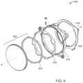
- FIG. 9is a diagram of an exploded view of a variable focus assembly.
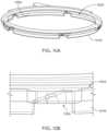
- FIGS. 10 A and 10 Bare diagrams showing example surface geometry at an interface between a shaper ring and a cam ring.
- FIG. 11is a diagram of another example variable focus assembly.
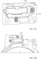
- FIGS. 12 A and 12 Bare diagrams of an example actuator.
- FIGS. 13 A- 13 Care diagrams of example coupling assemblies.
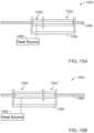
- FIG. 14is a diagram of another variable focus assembly.
- FIGS. 15 A and 15 Bare diagrams of an example shape memory alloy actuator.
- FIGS. 16 A- 16 Care diagrams of example coreless annular flux permanent magnet axial motors.
- FIGS. 17 and 18are diagrams of example printed windings for coreless annular flux permanent magnet axial motor.
- FIG. 19is a diagram of another example variable focus assembly.
- FIG. 20 Ais a diagram of an example annular flexure ring.
- FIG. 20 Bis a diagram of an example variable focus assembly including an annular flexure ring.
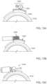
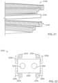
- FIG. 21is a diagram showing a partial cross-sectional view of a pair of variable focus assemblies for use in a display system.
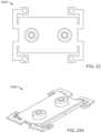
- FIGS. 22 , 23 , 24 A, and 24 Bare diagrams of an example active element of an actuator having multiple vibrational modes.
- FIG. 25is a diagram showing a partial cross-sectional view of a pair of variable focus assemblies for use in a display system.
- FIG. 26is a flow chart diagram of an example process of presenting image content to a user using a head-mounted display device.
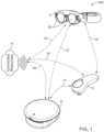
- FIG. 1shows an example augmented reality system 100 including a head-worn viewing component 2 , a hand-held controller component 4 , and an optional interconnected auxiliary computing or controller component 6 which may be configured to be worn as a belt pack or the like on the user.
- auxiliary computing or controller component 6which may be configured to be worn as a belt pack or the like on the user.
- Each of these componentsmay be communicatively connected to one another (e.g., via connections 10 , 12 , 14 , 16 , 17 , and 18 ) to communicate with each other and to other connected resources 8 (e.g., cloud computing or cloud storage resources).
- connected resources 8e.g., cloud computing or cloud storage resources
- one or more of the connections 10 , 12 , 14 , 16 , 17 , and 18can be wired couplings or wireless connections, such as those specified by Institute of Electrical and Electronics Engineers (IEEE) 802.11, Bluetooth®, and other connectivity standards and configurations.
- the viewing component 2includes one or more optical elements 20 that enable a user wearing the viewing component 2 to see the world around him in conjunction with virtual image information generated and presented by the system 100 (e.g., to facilitate an “augmented reality” experience).
- Such a system and experienceis described further in U.S. patent application Ser. Nos. 14/555,585, 14/690,401, 14/331,218, 15/481,255, and 62/518,539, each of which is incorporated by reference in its entirety.
- the optical elements 20can include one or more variable focus assemblies to present image information according to any suitable number of focal planes.
- the optical elements 20be configured to present image information according to a spectrum of focal plane that are selectable or tunable by an integrated control system (e.g., a control system included in the auxiliary computing or controller component 6 , or included in the viewing component 2 ).
- variable focus assembly 22is shown in FIGS. 2 A- 2 C and 3 .
- the optical element 22includes a lens 36 having a volume of fluid that is at least partially enclosed by a membrane. Further, the variable focus assembly 22 is configured such that upon rotation of a motor 24 , an associated mechanical drive assembly 26 rotationally drives a cam member 28 against a lever assembly 30 , which causes two opposing perimetric plates 38 and 40 to rotate (e.g., in directions 48 and 46 ) relative to a main housing assembly 41 , and rotate about associated rotation pin joints 32 and 34 . This causes the lens 36 to be squeezed (e.g., in directions 44 and 42 ) or released (e.g., in directions opposite 44 and 42 , respectively), depending upon the position of the motor 24 and the cam 28 . This squeezing, releasing, and reorientation of the opposing perimetric plates 38 and 40 relative to one another changes the focus of the lens 36 , thus providing an electromechanically adjustable variable focus assembly.
- variable focus assembly 22may be relatively bulky, and thus may be less suitable for use in a head-worn display device (e.g., the viewing component 2 ). Further, during operation of the variable focus assembly 22 , the opposing perimetric plates 38 and 40 are reoriented relative to each other (e.g., as each of them pivots at the bottom relative to the frame that couples the assembly). Thus, there may be a concomitant change in image position as the focus is varied. This introduces a complicating variable in presenting image information, which may make calibrating and/or configuring a head-worn display device more complex or resource intensive. Nevertheless, in some implementations, the variable focus assembly 22 can be used in a head-worn display device to present image information to a user according to multiple focal planes.
- variable focus assembliesare described below.
- a head-worn display devicecan include one or more of these variable focus assemblies, either in conjunction with or instead of the variable focus assembly 22 described above.
- FIGS. 8 A and 8 Bshow, in cross-section, an example liquid lens assembly 800 having a rotational cam ring configuration.
- the liquid lens assembly 800can be used, for example, as a variable focus assembly in a head-worn display device.
- the liquid lens assembly 800is operable to adjust a curvature of a membrane enclosing a fluid volume within the liquid lens assembly 800 , thereby changing an optical power of the liquid lens assembly 800 .
- light traveling through the fluid volumehas a wave front that can be altered when the light encounters the curved surface of the membrane enclosing the fluid volume.
- a change in the wave front of the lightcorresponds to a change in focus of the light.
- the liquid lens assembly 800includes a rigid refractive component 802 and a rigid shaper ring 804 .
- the refractive componentis composed, at least in part, of a solid, optically transparent material (e.g., plastic or glass), and can have flat surfaces, curved surfaces, or one flat and one curved surface (e.g., the surfaces 806 and 808 , respectively).
- the shaper ringis composed, at least in part, by a rigid material such as metal (e.g., aluminum, steel, or titanium), plastic, or other suitably lightweight and rigid materials.
- the liquid lens assembly 800includes an annular membrane 814 and a flexible lens membrane 810 .
- the flexible lens membrane 810spans the shaper ring 804 , such that the flexible lens membrane 810 is attached to the shaper ring 804 (e.g., secured directly onto the shaper ring 804 ) along the entire circumference of the shaper ring 804 to create a seal.
- a constant volume of substantially incompressible fluid 812is encapsulated between the flexible lens membrane 810 , the shaper ring 804 , the refractive component 802 , and the annular membrane 814 .
- the annular membrane 814is flexible to allow axial motion of the shaper ring 804 relative to the refractive component 802 while keeping the fluid 812 sealed within the liquid lens assembly 800 .
- the shaper ring 804can be moved towards the refractive component 802 along an optical axis 816 of the liquid lens assembly 800 (e.g., from the configuration shown in FIG. 8 A to the configuration shown in FIG. 8 B ).
- Thiscauses the flexible lens membrane 810 to be pressed against the fluid 812 , thereby increasing the curvature of the flexible lens membrane 810 and the fluid 812 .
- the optical power of the liquid lens assembly 800is increased.
- the shaper ring 804can be moved away from the refractive component 802 along the optical axis 816 (e.g., from the configuration shown in FIG. 8 B to the configuration shown in FIG. 8 A ). This causes the flexible lens membrane 810 to be moved away from the fluid 812 , thereby decreasing the curvature of the flexible lens membrane 810 and the fluid 812 . Correspondingly, the optical power of the liquid lens assembly 800 is decreased.
- FIG. 9shows an exploded view of a variable focus assembly 900 including the liquid lens assembly 800 , a cam ring 916 , a carrier frame 918 , and a cap 920 .
- a variable focus assembly 900including the liquid lens assembly 800 , a cam ring 916 , a carrier frame 918 , and a cap 920 .
- the components of the liquid lens assembly 800only the shaper ring 804 is shown individually.
- the liquid lens assembly 800nests within a cam ring 916 .
- the shaper ring 804 and the cam ring 916each include mechanical features (e.g., threads, grooves, lugs, splines, ramps, pins, teeth, protrusions, or other structures) that are engaged with one another, such that rotational motion of the cam ring 916 results in axial motion of the shaper ring 804 along the optical axis 816 .
- the axial motion of the shaper ring 804presses the flexible lens membrane 810 of the liquid lens assembly 800 against the fluid 912 or moves the flexible lens membrane 810 away from the fluid 812 , thereby causing the fluid 912 and the flexible membrane 810 to change shape (e.g., increasing or decreasing their curvatures, as described above).
- the cam ring 916 and liquid lens assembly 800can nest within a carrier frame 918 .
- the cam ring 916can be rotatable with respect to both the carrier frame 918 and the shaper ring 804 .
- the shaper ring 804can be constrained from rotating with respect to the carrier ring 918 (e.g., by one or more teeth, protrusions, or other structures).
- the shaper ring 804is axially movable with respect to both the cam ring 916 and the carrier frame 918 along the optical axis 922 .
- the cap 920can be fixed to the carrier frame 918 to secure the position of components that are housed within or mounted to the carrier frame (e.g., the cam ring 918 ).
- one or more actuator modulescan be used to adjust the optical power of the liquid lens assembly 800 .
- one or more actuator modulescan be used to impart a relative rotational motion between the cam ring 916 and both the carrier frame 918 and the shaper ring 804 , thereby causing the shaper ring 804 to move axially along the optical axis 816 relative to the refractive component 802 .
- FIGS. 10 A and 10 Bshow example surface geometry at an interface 1022 between the shaper ring 804 and the cam ring 916 .
- the shaper ring 804includes several lugs 1024 extending in an axial direction and engaging a helical spline 1026 on the cam ring 916 , such that an axial motion is imparted on the shaper ring 804 when the cam ring 916 rotates.
- other geometriessuch as ramps, steps, guide pins, and other mechanical features can be used to guide axial motion of the shaper ring 804 relative to the cam ring 916 .
- suitable geometriescan be used to convert relative rotation of the cam ring 916 with respect to the shaper ring 804 into axial movement of the shaper ring 804 with respect to the cam ring 916 .
- FIG. 11shows a perspective view of an example variable focus assembly 1100 .
- the variable focus assembly 1100includes a carrier frame 1118 , a cam ring 1116 , and a liquid lens assembly 1102 similar to the corresponding components described in FIGS. 8 , 9 , 10 A, and 10 B .
- variable focus assembly 1100includes an actuator 1126 fixed to the carrier frame 1118 .
- the actuator 1126is operable to transmit a substantially tangential force to the cam ring 1116 through a coupling assembly 1128 .
- the actuator 1126can include a single rotary motor fixed to the carrier frame 1118 and operably coupled to a radially protruding feature 1142 on the cam ring 1116 .
- the feature 1142can be fixed to or integrated with the cam ring 1116 .
- Actuation of the rotary motorcauses coupling assembly 1128 to extend or retract in a direction substantially tangential to the cam ring 1116 .
- Part of the coupling assemblyengages the feature 1142 and causes rotation of the cam ring relative to the carrier frame.
- the carrier frame 1118further includes a stop 1144 to limit the motion of coupling assembly 1128 and cam ring 1116 .
- the stop 1144can be used to prevent excessive strain on the flexible lens membrane element of the liquid lens assembly 1102 .
- suitable actuatorscan include stepper motors, servo motors, ultrasonic motors, rotary DC motors, piezoelectric actuators, shape memory alloy actuators, coreless annular flux axial motors, linear ultrasonic motors, rotary ultrasonic motors, other electromechanical actuators, or a combination thereof. Specific examples of different actuation mechanisms are discussed in further detail below. Further, example motors are provided in Appendix A.
- FIGS. 12 A and 12 Bshow a configuration in which the actuator 1226 is embedded within a radially extended portion of the carrier frame 1218 .
- the actuator 1226is a standing wave actuator.
- the position of the actuator 1226 within the recessed portion 1230 of carrier frame 1218may be adjustable for calibration. For instance, one or more set screws, spacers, or shims can be used for adjustment in at least one direction.
- a configuration in which the actuator 1226 is substantially contained within the recessed portion 1230may provide the advantage of minimizing motion between the actuator 1226 and the carrier frame 1218 , such that substantially all motion produced by the actuator is transferred to the driven element.
- such a configurationcan improve efficiency and accuracy of the variable focus assembly adjustment while helping to isolate the variable focus assembly from other components of the augmented reality (AR), virtual reality (VR), mixed reality (MR), and/or types of display systems in which such a variable focus assembly may be mounted.
- a housing surrounding actuator 1226can be provided to prevent dust or debris from the actuator from entering the sensitive mechanical and optical components.
- the housing(not shown) can be made from a material that facilitates the actuator operating at a preferred natural frequency within the variable focus assembly.
- the preferred natural frequency of the housingcan be at least an order of magnitude less than the operation frequency of the actuator 1226 .
- the operational frequency of the motoris approximately 90 KHz
- the preferred natural frequency of the housingcan be 9 KHz or less.
- sound output of the actuatormay also be considered.
- the actuatormay be advantageous for the actuator to operate with low noise output so that noise does not distract from the user experience when assembled in an augment reality (AR) system, virtual reality (VR) system, mixed reality (MR) system, or other display system.
- acceptable sound output of the actuatormay be less than 35 dBA, for instance between approximately 25 dBA to approximately 32 dBA.
- any sound that is produced by the actuatorsmay be at such a frequency that the sound is not detectable by humans and/or sensor devices (e.g., microphones) that may be used in AR systems, VR systems, MR systems, or other display systems.
- the sound produced by the actuatormay be at a frequency above approximately 30 kHz.
- the actuatorcan include a locking mechanism so that the assembly maintains its position when the actuator is not receiving power.
- a locking mechanismcan be achieved with a sufficiently high friction force between components within the actuator to prevent motion from occurring, even if there is back force on the actuator from the liquid lens assembly.
- mechanical stops, ratchets, augers, or other mechanical features of components within the actuatorcan be included to provide a locking function of the actuator.
- a separate lockmay be implemented in addition to or instead of the locking feature in the actuator unit; however, such a locking element may increase friction within the moving components of the variable focus assembly.
- Wear mitigation techniquessuch as lubricating the moving components with polytetrafluoroethylene (PFTE), finely machining or polishing interface surfaces, or coating interface surfaces with materials such as diamond-like carbon (DLC) coating, can improve wear characteristics in systems with friction between moving components.
- PFTEpolytetrafluoroethylene
- DLCdiamond-like carbon
- actuators per variable focus assemblyWhile the use of one actuator per variable focus assembly is discussed above, multiple actuators per variable focus assembly can be used, as discussed in greater detail below.
- FIGS. 13 A- 13 Cshow several examples coupling assemblies.
- a coupling assemblyincludes multiple gears 1332 and a pinion drive 1334 .
- the gears 1332can transfer motion from an actuator (not shown) to a cam ring 1316 through a gear rack 1336 fixed to the cam ring 1316 .
- the cam ring 1316can be similar to the cam rings described above.
- a coupling assemblyincludes a worm drive 1338 that transfers motion to a cam ring 1316 through a gear rack 1336 .
- a coupling assemblyincludes a lead screw and nut assembly 1340 that transfers motion to a cam ring 1316 through a gear rack 1336 .
- Each of the coupling assembliescan have inner and outer limits so that rotation of the cam ring 1316 is restricted within a particular range.
- stops(not shown) can be included in the system to prevent excessive motion of the cam ring 1316 .
- coupling assembliescan also include elements or features that reduce irregular or off-axis motion of the actuator and prevent such motions from being transferred to driven elements (e.g., the cam ring).
- driven elementse.g., the cam ring
- a wobble coupling or a drive dogcan be used to decouple wobble motion, parasitic motion, yaw moments, roll moments, and/or pitch moments from the driven element.
- reducing these moments and motion at the driven elementcan improve alignment of the cam ring and shaper ring relative to the carrier frame. Further, precise alignment can improve the accuracy of the variable focus assembly and reduce wear on the moving components of the system.
- the focus of the variable focus assemblycan be adjusted by precisely controlling the curvature of the flexible lens membrane (e.g. such that a particular focus or optical power is achieved).
- a closed-loop feedback systemcan be used to adjust the position of one or more components of the variable focus assembly relative to another (e.g., by controlling the operation of one or more actuators based on one or more position measurements).
- a position sensore.g., a Hall sensor
- an optical encodercan be used to detect the actual positions of one or more moving components within the variable focus assembly.
- Actual position information from one or more sensorscan be sent to a control loop, where a processor (e.g., a microprocessor) compares the actual position data to the expected position of moving components. If a difference between the actual position and the expected position is above a desired threshold, the processor can adjust input to the actuator until the actual position is within a threshold tolerance of the expected position.
- a processore.g., a microprocessor
- FIG. 14shows another example variable focus assembly 1400 .
- the variable focus assembly 1400includes a carrier frame 1418 , a cam ring 1416 , and a liquid lens assembly 1402 similar to the corresponding components described in FIGS. 8 , 9 , 10 A, and 10 B .
- variable focus assembly 1400includes a shape memory alloy (SMA) material actuator 1428 for rotating the cam ring 1416 relative to the carrier frame 1418 and the liquid lens assembly 1402 .
- the actuator 1428includes a SMA wire 1430 , a return spring 1432 , and a heat source 1434 thermally coupled to the SMA wire 1430 ).
- the SMA wire 1430extends circumferentially within a recessed channel on the carrier frame 1418 .
- One end of the SMA wire 1430is fixed to the carrier frame 1418 and the other end is directly or indirectly coupled to the cam ring 1416 .
- the SMA wire 1430is heated (e.g., using the heat source 1434 )
- the length of the SMA wire 1430decreases such that the end connected to cam ring 1416 moves toward the end connected to carrier frame 1418 .
- the change in length of the SMA wire 1430causes the end connected to cam ring 1416 to move toward the end connected to carrier frame 1418 , thereby rotating cam ring 1416 relative to the carrier frame 1418 .
- the SMA wire 1430When the SMA wire 1430 cools, it expands to its original length and causes the cam ring 1416 to rotate back to its original position.
- the amount of motion between the cam ring 1416 and the carrier frame 1418can be controlled to finely adjust the curvature of the flexible membrane and fluid chamber of the liquid lens assembly 1402 .
- the return spring 1432can bias the cam ring 1416 , such that it returns to its original position relative to the carrier frame 1418 when the SMA wire 1430 is lengthened (e.g., when the SMA wire cools).
- the SMA wire 1430can be composed, at least in part, of copper-aluminum-nickel and/or nickel-titanium (NiTi). In some implementations, the SMA wire 1430 can be composed of an alloy of zinc, copper, gold and iron.
- FIGS. 15 A and 15 Bshow another example SMA actuator 1500 .
- the actuator 1500includes a SMA spring 1560 opposed by a bias spring 1562 .
- the SMA spring 1560 and bias spring 1562are housed within a frame 1564 that limits the total length of the SMA spring and bias spring assembly.
- the frame 1564includes a hole for a linkage wire 1566 to enter the frame 1564 and connect to at least one of the SMA spring 1560 and the bias spring 1562 .
- the activation state of the SMA spring 1560can be control by applying heat to the SMA spring 1560 (e.g., by a heat source 1568 thermally coupled to the SMA spring 1560 ) or cooling the SMA spring 1560 .
- Actuation of the SMA spring 1560causes elongation of the SMA spring 1560 and a contraction of the bias spring 1562 .
- Linkage wire 1556is shifted as the SMA spring 1560 actuates and is operable to transfer force to a driven component (e.g., a cam ring or other drive component coupled to the linkage wire 1566 ).
- FIGS. 16 A and 16 Bshow another example actuator 1600 a configured to adjust a variable focus assembly (e.g., one or more of the variable focus assemblies described herein).
- FIG. 16 Ashows the actuator 1600 a according to a side (axial) view
- FIG. 16 Bshows the actuator 1600 a according to an side (axial) view in which the components of the actuator 1600 a have been “unfolded” into a linear configuration for illustrative purposes.
- the actuator 1600 ais a coreless annular flux permanent magnet axial motor that includes permanent magnets 1666 placed in a particular arrangement around at least a portion of the annular opening of either a cam ring 1616 or the carrier frame (not shown in FIGS. 16 A and 16 B ) of a variable focus assembly.
- the motorfurther includes electrical windings 1668 placed around at least a portion of the annular opening of the carrier frame or the cam ring 1616 so that the permanent magnets 1666 and electrical windings 1668 are mounted to separate components.
- the electrical windings 1668can be made using conductive material printed on printed circuit board (PCB).
- PCBprinted circuit board
- the PCBcan then be cut to size and mounted to the carrier frame or cam ring 1616 .
- multiple layers of the PCBcan be stacked on top of each other, each layer having printed windings, so that the density of the windings is increased. Higher density of windings can provide higher torque output.
- FIG. 16 Bshows a variation of the coreless annular flux permanent magnet axial motor of FIG. 16 A .
- the motor 1600 b shown in FIG. 16 Bincludes a second set of permanent magnets 1666 b such that the PCB windings 1668 are between a first set of permanent magnets 1666 a and a second set of permanent magnets 1666 b .
- the permanent magnets 1666 a and 1666 bcan be arranged in a Halbach array.
- Example patterns of printed windings 1668are shown in FIGS. 17 and 18 .
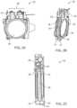
- FIGS. 4 A and 4 Bshow an example variable focus assembly 50 having a perimetric frame configuration.
- the variable focus assembly 50includes a fluid/membrane lens 36 interposed between two rigid perimetric frame members 70 and 72 . Further, rotatable adjustment perimetric member 52 and 54 are disposed between the fluid/membrane lens 36 and each of the rigid perimetric frame members 70 and 72 .
- the actuation motor 64 adjustment perimetric members 52 and 54can be rotatably adjusted relative to the rigid perimetric frame members 70 and 72 using a compact actuation motor 64 (e.g., a stepper motor, servo motor, ultrasonic motor, or other electromechanical actuator). As shown in FIG. 4 B , the actuation motor 64 can be coupled to the rigid perimetric frame members 56 and 58 and to the rotatable adjustment perimetric members 52 and 54 using a coupling assembly having a shaft 62 coupled to a barrel member 60 which is coupled to a pin 61 that interfaces with the rotatable adjustment perimetric members 52 and 54 .
- a compact actuation motor 64e.g., a stepper motor, servo motor, ultrasonic motor, or other electromechanical actuator.
- the actuation motor 64can be coupled to the rigid perimetric frame members 56 and 58 and to the rotatable adjustment perimetric members 52 and 54 using a coupling assembly having a shaft 62 coupled to a
- the mechanical interface between the rotatable adjustment perimetric members 52 and 54 and the rigid perimetric frame members 70 and 72can one or more include perimetrically located features (e.g., such as ramps, bumps, or step-ups) that cause the inter-coupled fluid/membrane lens 36 to be squeezed or loosened with a substantially even perimetric loading, such as by three or more interfacial feature groupings (e.g., one at every 120 degrees around the 360 degree perimetric interfaces between the rotatable adjustment perimetric members 52 and 54 and the rigid perimetric frame members 70 and 72 .
- the fluid/membrane lens 36can be loosened or tightened relatively evenly, preferably without substantial movement or reorientation of the image position relative to the plane of the lens.
- FIGS. 5 , 6 , 7 A and 7 Bshow other example configurations for providing substantially even perimetric loading (and thus focus adjustment without substantial movement or reorientation of image position) for a compact variable focus assembly having an inter-coupled fluid/membrane lens 36 .
- an example compact variable focus assembly 68includes two rigid perimetric frame members 70 and 72 and an inter-coupled fluid/membrane lens 36 .
- Substantially even perimetric loading of the fluid/membrane lens 36is provided by several electromagnetic actuators 76 , 77 , and 78 , which are configured to controllably urge or repel the two rigid perimetric frame members 70 and 72 relative to each other to provide controllable focal adjustment.
- the electromagnetic actuators 76 , 77 , and 78can be placed equidistantly from each other perimetrically (e.g., about 120 degrees from each other) to provide even loading with a 3-actuator configuration.
- Other implementationscan include more actuators, such as four actuators at 90 degrees apart, etc.
- another example compact variable focus assembly 74includes two rigid perimetric frame members 70 and 72 and an inter-coupled fluid/membrane lens 36 .
- Substantially even perimetric loading of the fluid/membrane lens 36is provided by several shape memory metal alloy actuators 80 , 82 , and 84 , which are configured to controllably urge or repel the two rigid perimetric frame members 70 and 72 relative to each other to provide controllable focal adjustment.
- the shape memory metal alloy actuators 80 , 82 , and 84can be placed equidistantly from each other perimetrically (e.g., about 120 degrees from each other) to provide even loading with a 3-actuator configuration.
- Other implementationscan include more actuators, such as four actuators at 90 degrees apart, etc.
- another example compact variable focus assembly 76includes two rigid perimetric frame members 70 and 72 and an inter-coupled fluid/membrane lens 36 .
- Substantially even perimetric loading of the fluid/membrane lens 36is provided by several piezoelectric actuators 86 , 88 , and 90 , which are configured to controllably urge or repel the two rigid perimetric frame members 70 and 72 relative to each other to provide controllable focal adjustment.
- the piezoelectric actuators 80 , 82 , and 84can be placed equidistantly from each other perimetrically (e.g., about 120 degrees from each other) to provide even loading with a 3-actuator configuration.
- each of the piezoelectric actuatorscan include an assembly of a series of individual piezoelectric devices (e.g., 92 , 94 , etc.) that are inter-coupled such that activation of each provides a given mechanical throw which is added to others in the assembly to produce an overall assembly throw which is suitable for the application.
- individual piezoelectric devicese.g., 92 , 94 , etc.
- variable focus assemblies shown in FIGS. 5 - 7can include several actuators around the circumference of the assembly. In some implementations, it may be advantageous to reduce the number of actuators used (e.g., in order to reduce size, weight, and power requirements of the variable focus assembly).
- FIG. 19shows another example variable focus assembly 1900 having a single actuator 1926 .
- the actuator 1926can be a linear ultrasonic motor that is connected to a shaper ring 1904 by a linkage 1928 .
- the actuator 1926causes the linkage 1928 and the shaper ring 1904 to move axially toward and away from the fixed refractive component 1902 , which causes a change in curvature of flexible lens membrane 1910 and the shape of fluid compartment 1912 .
- the refractive componentcan be moved toward and away from a fixed shaper ring.
- variable focus assembly 1900can include an annular membrane 1914 that is flexible to allow axial motion between the refractive component 1902 and the shaper ring 1904 .
- this flexibilitycan also cause a moment, M, on the shaper ring 1904 when the linkage 1928 is moving in the z direction.
- the moment, Mcan cause the shaper ring 1904 and the flexible lens membrane 1910 attached to the shaper ring to tilt, such that the curvature of flexible lens membrane 1910 is no longer symmetric about the central axis, C.
- light passing through the asymmetric curvaturemay become distorted.
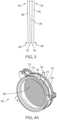
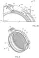
- FIG. 20 Ashows a top view of an example annular flexure ring 2000 .
- the annular flexure ring 2000can be included in the variable focus assembly to support and reinforce the annular membrane 1914 , as shown in the assembly cross section view of FIG. 20 B .
- Outer portions of the annular flexure ring 2000can be fixed to the shaper ring 1904 , while inner portions of the annular flexure ring 2000 can be fixed to the refractive component 1902 .
- the annular flexure ring 2000can be made from a rigid material such as metal (aluminum, steel, or titanium), plastic, or other suitable material.
- the annular flexure ring 2000can include slots that allow the annular flexure ring 2000 to change shape in a radial direction in response to the axial load applied to it as the linkage 1928 moves the shaper ring 1904 .
- the rigidity of the annular flexure ring 2000reduces the moment M such that a single actuator configuration can maintain a symmetric curvature of flexible lens membrane 1910 over a range of positions.
- Pairs of variable focus assembliessuch as an inner lens assembly (ILA) and an outer lens assembly (OLA) can be used in a display system (e.g., AR system, MR system, etc.), to impart one of a range of focal depths to virtual content using the ILA while correcting or compensating for distorted environmental light using the OLA.
- FIG. 21shows a partial cross-sectional view of a pair of variable focus assemblies 2146 and 2148 with an augmented reality eyepiece 2150 in between.
- the ILA 2146 and the OLA 2148are disposed on either side of the eyepiece 2150 .
- Virtual images from the eyepiece 1250are projected toward the ILA 2146 , and are shaped by the ILA 2146 before being emitted towards the user.
- Light from the surrounding environmentis shaped a first time by the OLA 2148 and is shaped a second time by the ILA 2146 , such that the net change in focus of the environmental light is zero after the two shaping events (e.g., the optical power of the OLA 2148 is the inverse of the optical power of the ILA 2146 ).
- the optical powers of the OLA 2148 and the ILA 2146can be adjusted by a control module (e.g., a computing system having one or more computer processors) during operation of the display system.
- a control modulecan control one or more of the actuator modules of the display system to selectively adjust the optical power of the ILA 2146 (e.g., such that virtual images from the eyepiece 1250 are presented to user according to one or more selected focal planes).
- the control modulecan concurrently control the actuator modules to adjust the optical power of the OLA 2148 , such that the optical power of the OLA 2148 is the inverse of the optical power of the ILA 2146 (e.g., to correct or compensate for distorted environmental light by the ILA 2146 ).
- the control modulecan be included in one or more of the display system (e.g., the head-worn viewing component 2 , the hand-held controller component 4 , and/or the interconnected auxiliary computing or controller component 6 ).
- the diameter of the OLA 2148can be larger than that of the ILA 2146 .
- Example specifications of the ILA 2146 and the OLA 2148are provided in Appendix B and Appendix C, respectively.
- Each of the ILA 2146 and the OLA 2148can be implemented as any of the variable focus assemblies described herein. Further, each of the ILA 2146 and the OLA 2148 can be actuated using any of the actuation configurations described herein.
- FIG. 25is a cross-sectional view of an example system 2500 having a pair of variable focus assemblies similar to the configuration shown in FIG. 21 .
- the system 2500couples the moving component of ILA 2546 to the moving component of OLA 2548 so that both moving components can be driven by one or more common actuator(s) 2526 and a common linkage 2528 .
- the common actuator 2526can be a linear ultrasonic motor.
- the moving component of the ILA 2246is the ILA refractive component 2502 and the moving component of the OLA 2248 is the OLA shaper ring 2504 .
- the OLA assemblytravels a different axial distance than the ILA assembly in order for the net diopter change of environmental light traveling through both the OLA and ILA assemblies to equal zero.
- Various spring forcescan be added into the system (e.g., by the flexible lens membrane of one or more of the ILA and the OLA) to drive both moving components at a different rate. Specifically, a spring force can be added to the drive linkage for the lens requiring less travel.
- An additional calibration consideration for a coupled system 2500is compensation for optical changes caused by thermal drift.
- One component of thermal driftis the expansion of the optical fluid within the liquid lens assemblies when exposed to heat. Expansion of the fluid increases the curvature of the flexible lens membrane and increases optical power imparted by the fluid lens.
- Another component of thermal drift in optical system 2500is the expansion of support elements, such as the linkage 2552 and the ground element 2554 .
- the ground element 2254expands, it compresses the OLA refractive component toward the OLA shaper ring and compresses the ILA shaper ring toward the ILA refractive component.
- expansion of the ground element 2254also increases the optical power of the OLA and the ILA.
- the optical power change at the ILAcan cause virtual images to appear at a different focal depth than intended. Further, the optical power change at the OLA does not typically correspond exactly to the optical power change at the ILA. As a result, environmental light passing through the OLA and ILA can appear defocused.
- the material of the linkage 2252can be selected to have a particular coefficient of thermal expansion (CTE) to balance the system.
- CTEcoefficient of thermal expansion
- the CTE of linkage 2252can be selected such that it allows a sufficient degree of material expansion to maintain a predicted relative position between the shaper and refractive components of both the ILA and the OLA (e.g., such that the rigid refractive component of the ILA and the shaper ring of the OLA due to the variation in the temperature is less than a threshold value within a particular temperature range).
- the linkage 2252can be formed from a polymer having a relatively high coefficient of thermal expansion.
- the linkage 2252When the linkage 2252 is exposed to the same thermal conditions as the optical fluid and ground element 2254 , the linkage 2252 expands to reduce compression of the OLA refractive against the OLA shaper and to reduce compression of the ILA refractive with respect to the ILA shaper.
- the threshold valuecan be 0.01 mm or less, 0.1 mm or less, 1 mm or less, or some other threshold value.
- the temperature rangecan be the expected operating temperature range of the device. As an example, the lower bound of the temperature range could be ⁇ 20° C., ⁇ 10° C., 0° C., 10° C., 20° C., 30° C., 40° C., 50° C., or some other temperature.
- the higher bound of the temperature rangecould be 20° C., 30° C., 40° C., 50° C., 60° C., 70° C., 80° C., 90° C., 100° C., 110° C., 120° C., 130° C., or some other temperature.
- the actuator(s) employed in the variable focus assemblycan include one or more actuators that each has multiple vibrational modes. Simultaneous excitation of the multiple vibrational modes of the actuator can lead to a compound vibration of the actuator to enable control of the components of the variable focus assembly.
- FIG. 22shows an example schematic of an active element of an actuator having multiple vibrational modes, which can be employed in a variable focus assembly in some embodiments.
- the actuatorcan also be described as a traveling wave ultrasonic motor with multiple modes.
- the actuatorcan be a linear driving type of actuator, and can be referred to as a linear actuator or linear motor.
- the active element 2200can include a plate 2202 composed at least party of a piezoelectric material (e.g., a ceramic). Coupling components 2204 can be attached to the plate 2202 (e.g., secured directly onto plate 2202 ) using attachment arms 2206 .
- the coupling components 2204can be attached to fixed points (e.g., mechanical ground) in the variable focus assembly (e.g., one or more points on the shaper ring, cam ring, carrier frame, etc.).
- the attachment arms 2206can be articulated into multiple segments, as in the example shown, at least in part to reduce the length of the actuator.
- the components 2208can be coupled to components of the variable focus assembly, such as lens surfaces. Overall linear movement of the components 2208 relative to each other during operation of the actuator can cause the relative movement of the attached variable focus assembly components.
- FIG. 22shows example dimensions (in mm) of components of the active element 2200 . Some implementations employ different suitable values for the illustrated dimensions.
- FIG. 23shows an example schematic 2300 of a top-down view of the active element 2200 of the actuator.
- FIGS. 24 A and 24 Bshow respective example schematics 2400 and 2402 of the active element 2200 .
- FIG. 24 Aillustrates a first mode of vibration (e.g., a “cylinder” or “pipe” mode) in which the long edges of the active element are displaced up and down in the z-direction relative to the components 2208 .
- FIG. 24 Billustrates a second mode of vibration (e.g., a “sinusoidal” mode) in which the short edges of the active element are displaced along the y-direction, in opposite directions from one another.
- a first mode of vibratione.g., a “cylinder” or “pipe” mode
- a second mode of vibratione.g., a “sinusoidal” mode
- the active elementcan be configured such that its overall length (e.g., 11.63 mm in the example shown in FIG. 22 ) is sufficiently short to enable use of the actuator in the variable focus assembly, which may be limited in its available maximum depth or clearance when employed in a head-worn viewing component of a display system such as a VR system, an AR system, a MR system, or other type of system.
- the active element 2200can be configured such that the natural frequencies of the multiple (e.g., two) fundamental vibrational modes of the active element 2200 are the same or sufficiently close to one another. This consideration provides for efficient operation of the actuator, as the efficiently may fall off as the difference between the frequencies increases.
- the active elementcan be configured such that the frequencies are within 1.5% of each other.
- the frequenciescan be be approximately 90 kHz, and/or within a range from 88 kHz to 94 kHz.
- the frequency of the first modecan 88.9 kHz and the frequency of the second mode can 93.8 kHz.
- the active elementcan be configured such that there are no other natural frequencies of the active element that are within approximately 5% of the operating frequency of the modes to be excited (e.g., the cylinder and sinusoidal modes).
- the nearest natural frequency to these modescan be at least 5 kHz away from the excited frequency, such that the undesired vibration mode is not excited by the drive frequency. Ensuring that other undesired modes are not excited can provide for efficient operation of the actuator.
- switching of depth planes based on liquid lens pairsmay necessitate use of actuator(s) that are consistent with the form factor and/or industrial design of an AR, a VR, or a MR glass or headsets.
- the active element outlineis shown the example of FIG. 22 .
- the boundary conditionse.g., maximum length
- the boundary conditionscan be an important consideration in determining the natural frequencies of the active element.
- the natural frequencies of the two vibrational modescan match or be sufficiently close to one another (e.g., ⁇ 5%, ⁇ 10%, or ⁇ 15).
- the configurationcan be modified to alter the vibrational frequencies such that they match one another or are sufficiently close to one another.
- the actuatorcan be configured to minimize the length of the active element while maintaining matched natural frequencies that are approximately 90 kHz.
- FIG. 26is a flow chart diagram of an example process 2600 of presenting image content to a user using a head-mounted display device.
- the process 2600can be performed, at least in part, using one or more of the systems or apparatus described herein.
- lightis generated using a light projector of a head-mounted display device (step 2602 ).
- An example head-mounted display deviceis described, for example, with respect to FIG. 1 .
- the lightis directed to an eye of a user using an optical assembly of the head-mounted display device (step 2604 ).
- the optical assemblyincludes a variable focus lens assembly include a rigid refractive component, a shaper ring defining an aperture, a flexible lens membrane between the shaper ring and the rigid refractive component, and an actuator module coupled to the variable focus lens assembly.
- the flexible lens membranecovers the aperture.
- the rigid refractive component, the shaper ring, and the flexible lens membraneare arranged along an axis.
- the rigid refractive component and the flexible lens membranedefine a chamber between the flexible lens membrane and the refractive component. A volume of fluid is disposed within the chamber.
- Example variable focus lens assemblies and their respective componentsare described, for example, with respect to FIGS. 2 - 25 .
- the head-mounted display deviceincludes an actuator module coupled to the variable focus lens assembly.
- Adjusting the optical power of the optical assemblyincludes moving the shaper ring relative to the rigid refractive component along the axis using the actuator module, such that a curvature of the flexible lens membrane in the aperture is modified. Examples of this adjustment technique are described, for instance, with respect to FIGS. 8 A and 8 B .
- adjusting the optical power of the optical assemblycan include increasing the curvature of the flexible lens membrane by moving the shaper ring towards the rigid refractive component along the axis. In some implementations, adjusting the optical power of the optical assembly can include decreasing the curvature of the flexible lens membrane by moving the shaper ring away from the rigid refractive component along the axis.
- variable focus lens assemblycan also include a carrier frame, and a cam ring nested within the carrier frame, where the shaper ring is nested within the cam ring.
- Adjusting the optical power of the optical assemblycan include rotating, using the actuator module, the cam ring relative to the carrier frame about the axis to cause the shaper ring to move relative to the rigid refractive component along the axis. Examples of this adjustment technique are described, for instance, with respect to FIGS. 9 , 10 A, 10 B, 11 , 12 A, 12 B, and 13 A- 13 C .
- the actuator modulecan include a shape memory alloy wire coupled to the cam ring, and a heat source configured to apply heat to the shape memory alloy wire.
- Adjusting the optical power of the optical assemblycan include applying heat to the shape memory alloy wire to change in a length of the shape memory alloy wire and to rotate the cam ring relative to the carrier frame about the axis. Examples of this adjustment technique are described, for instance, with respect to FIG. 14 .
- the actuator modulecan include a shape memory alloy spring, a bias spring opposing the shape memory alloy spring, a linkage wire coupled to (i) one of the shape memory alloy spring or the bias spring and (ii) the cam ring, and a heat source configured to apply heat to the shape memory alloy wire.
- Adjusting the optical power of the optical assemblycan include applying heat to the shape memory alloy wire to change in a length of the shape memory alloy spring and to rotate the cam ring relative to the carrier frame about the axis. Examples of this adjustment technique are described, for instance, with respect to FIGS. 15 A and 15 B .
- the actuator modulecan include one or more permanent magnets disposed along a periphery of one of the carrier frame or the cam ring, and electrical windings disposed along a periphery of the other one of the carrier frame or the cam ring opposite the one or more permanent magnets.
- Adjusting the optical power of the optical assemblycan include applying electrical current to the electrical windings to rotate the cam ring relative to the carrier frame about the axis. Examples of this adjustment technique are described, for instance, with respect to FIGS. 16 A- 16 C, 17 , and 18 .
- the actuator modulecan include a plate having a piezoelectric material, and one or more arms extending from the plate and coupled to a mechanical ground, one or more mounting structures disposed on the plate. Each mounting structure can be mounted to a respective portion of the optical assembly. Adjusting the optical power of the optical assembly can include vibrating the plate according to at least two vibration modes. Examples of this adjustment technique are described, for instance, with respect to FIGS. 22 , 23 , 24 A, and 24 B .
- the platecan include a pair of opposing first edges extending a first direction, and a pair of opposing second edges extending a second direction orthogonal to the first direction, where the first edges are longer than the second edges.
- Vibrating the plate according to according to a first vibration mode of the at least two vibration modescan include displacing the first edges relative to a center of the plate in a third direction orthogonal to the first direction and the second direction (e.g., as shown in FIG. 24 A ).
- Vibrating the plate according to according to a second vibration mode of the at least two vibration modescan include displacing the second edges relative to one another in the second direction (e.g., as shown in FIG. 24 B ).
- the optical assemblycan include a second variable focus lens assembly concentric with the variable focus lens assembly.
- the process 2600can include adjusting an optical power of the second variable focus lens assembly concurrently with adjust the optical power of the variable focus lens assembly, such that the optical power of the variable focus lens assembly is the inverse of the optical power of the second variable focus lens assembly (e.g., as described with respect to FIG. 25 ).
- directing the light to the eye of the usercan include directing the light through one of the variable focus lens assembly or the second variable focus lens assembly to the eye of the user.
- Appendix Alists an example specification for actuator(s) that may be employed in some embodiments.
- Appendix Blists an example specification for an Inner Lens Assembly that may be employed in some embodiments.
- Appendix Clists an example specification for an Outer Lens Assembly that may be employed in some embodiments. Embodiments are not limited to these examples, and other suitable values may be employed.
- the inventionincludes methods that may be performed using the subject devices.
- the methodsmay comprise the act of providing such a suitable device. Such provision may be performed by the end user.
- the “providing” actmay include one or more steps in which the end user may obtain, access, approach, position, set-up, activate, power-up or otherwise act to provide the requisite device in the subject method.
- Methods recited hereinmay be carried out in any order of the recited events which is logically possible, as well as in the recited order of events.
- Thrust and start thrust⁇ 1 N to ⁇ 4 N
- Positioning accuracy(allowable motor error motions for six degrees of freedom): ⁇ 0.2 mm
- Duty Cycle12 million switches at a frequency of 0.3*Hz
- Form Factor of motorDimensions ⁇ 33 ⁇ 16 ⁇ 9.2 mm
- Form Factor for actuated elements⁇ 40 mm with distributed load
- Allowable deformation of mechanical components and mounting locations⁇ 0.020-0.300 mm
- Usage environmentambient temperature range of ⁇ 10° C. to +55° C., non-condensing humidity 5-95%
- Appendix BExample Inner Lens Assembly (“ILA”) Specifications
- Travel range721 ⁇ m. In some examples, travel range is the combination of alignment offset and the actual motion requirements of the system
- Travel range760 ⁇ m. In some examples, travel range is the combination of alignment offset and the actual motion requirements of the system
- Moving shaper ring mass0.72 grams
Landscapes
- Physics & Mathematics (AREA)
- General Physics & Mathematics (AREA)
- Optics & Photonics (AREA)
- Lens Barrels (AREA)
- Mechanical Light Control Or Optical Switches (AREA)
- Eyeglasses (AREA)
- Lenses (AREA)
Abstract
Description
Claims (8)
Priority Applications (1)
| Application Number | Priority Date | Filing Date | Title |
|---|---|---|---|
| US17/614,248US12332444B2 (en) | 2019-05-24 | 2020-05-22 | Variable focus assemblies |
Applications Claiming Priority (6)
| Application Number | Priority Date | Filing Date | Title |
|---|---|---|---|
| US201962852940P | 2019-05-24 | 2019-05-24 | |
| US201962852915P | 2019-05-24 | 2019-05-24 | |
| US201962864229P | 2019-06-20 | 2019-06-20 | |
| US201962864253P | 2019-06-20 | 2019-06-20 | |
| PCT/US2020/034406WO2020243014A1 (en) | 2019-05-24 | 2020-05-22 | Variable focus assemblies |
| US17/614,248US12332444B2 (en) | 2019-05-24 | 2020-05-22 | Variable focus assemblies |
Related Parent Applications (1)
| Application Number | Title | Priority Date | Filing Date |
|---|---|---|---|
| PCT/US2020/034406A-371-Of-InternationalWO2020243014A1 (en) | 2019-05-24 | 2020-05-22 | Variable focus assemblies |
Related Child Applications (1)
| Application Number | Title | Priority Date | Filing Date |
|---|---|---|---|
| US19/205,124ContinuationUS20250271675A1 (en) | 2019-05-24 | 2025-05-12 | Variable focus assemblies |
Publications (2)
| Publication Number | Publication Date |
|---|---|
| US20220221710A1 US20220221710A1 (en) | 2022-07-14 |
| US12332444B2true US12332444B2 (en) | 2025-06-17 |
Family
ID=73456867
Family Applications (3)
| Application Number | Title | Priority Date | Filing Date |
|---|---|---|---|
| US16/882,075Active2040-09-14US11624919B2 (en) | 2019-05-24 | 2020-05-22 | Variable focus assemblies |
| US17/614,248Active2041-02-19US12332444B2 (en) | 2019-05-24 | 2020-05-22 | Variable focus assemblies |
| US19/205,124PendingUS20250271675A1 (en) | 2019-05-24 | 2025-05-12 | Variable focus assemblies |
Family Applications Before (1)
| Application Number | Title | Priority Date | Filing Date |
|---|---|---|---|
| US16/882,075Active2040-09-14US11624919B2 (en) | 2019-05-24 | 2020-05-22 | Variable focus assemblies |
Family Applications After (1)
| Application Number | Title | Priority Date | Filing Date |
|---|---|---|---|
| US19/205,124PendingUS20250271675A1 (en) | 2019-05-24 | 2025-05-12 | Variable focus assemblies |
Country Status (5)
| Country | Link |
|---|---|
| US (3) | US11624919B2 (en) |
| EP (2) | EP3977182A4 (en) |
| JP (2) | JP2022532931A (en) |
| CN (2) | CN114270228A (en) |
| WO (2) | WO2020243014A1 (en) |
Families Citing this family (24)
| Publication number | Priority date | Publication date | Assignee | Title |
|---|---|---|---|---|
| AU2018284089B2 (en) | 2017-06-12 | 2022-12-15 | Magic Leap, Inc. | Augmented reality display having multi-element adaptive lens for changing depth planes |
| GB201800933D0 (en)* | 2018-01-19 | 2018-03-07 | Adlens Ipr Ltd | Improvements in or relating to variable focal power optical elements,a variable focal power optical device, a display module for augmented reality headset |
| US12298519B2 (en) | 2018-09-24 | 2025-05-13 | Apple Inc. | Display system with interchangeable lens |
| US20200297572A1 (en)* | 2019-03-19 | 2020-09-24 | Optotune Ag | System for eye training and use of the system for eye training |
| WO2020226791A1 (en)* | 2019-05-07 | 2020-11-12 | Apple Inc. | Adjustment mechanism for head-mounted display |
| US11624919B2 (en)* | 2019-05-24 | 2023-04-11 | Magic Leap, Inc. | Variable focus assemblies |
| KR102723835B1 (en) | 2019-06-21 | 2024-10-31 | 애플 인크. | Display and vision correction system with removable lenses |
| CN112241068B (en)* | 2019-07-18 | 2024-12-03 | 三星电子株式会社 | Image display device capable of expressing multiple depths |
| WO2021010772A1 (en) | 2019-07-18 | 2021-01-21 | 삼성전자(주) | Image display device capable of expressing multiple depth |
| WO2022032198A1 (en) | 2020-08-07 | 2022-02-10 | Magic Leap, Inc. | Tunable cylindrical lenses and head-mounted display including the same |
| CN114911076A (en)* | 2021-02-07 | 2022-08-16 | 奥普托图尼股份公司 | Tunable optics |
| JP2024514416A (en) | 2021-03-15 | 2024-04-02 | マジック リープ, インコーポレイテッド | Optical devices and head-mounted displays employing adjustable cylindrical lenses |
| GB2605399B (en)* | 2021-03-30 | 2025-04-30 | Bae Systems Plc | Projector |
| CN113489876B (en)* | 2021-07-26 | 2023-05-23 | 维沃移动通信有限公司 | Camera module and electronic equipment |
| US20250028167A1 (en)* | 2021-11-23 | 2025-01-23 | Optotune Switzerland Ag | Tunable optical component |
| US12392987B2 (en) | 2022-11-11 | 2025-08-19 | Htc Corporation | Head-mounted display device and adjustment module |
| TWI828418B (en)* | 2022-11-11 | 2024-01-01 | 宏達國際電子股份有限公司 | Head-mounted display device and adjustment module |
| TWI821090B (en)* | 2022-12-30 | 2023-11-01 | 宏達國際電子股份有限公司 | Head-mounted display device and zoom lens module |
| US12326577B2 (en)* | 2022-12-30 | 2025-06-10 | Htc Corporation | Head-mounted display device and zoom lens module |
| GB2639180A (en)* | 2024-03-04 | 2025-09-17 | Cambridge Mechatronics Ltd | Optical assembly |
| TWI856819B (en)* | 2023-09-15 | 2024-09-21 | 新鉅科技股份有限公司 | Optical focus adjustment module and head mounted electronic device |
| WO2025063445A1 (en)* | 2023-09-22 | 2025-03-27 | 삼성전자주식회사 | Display assembly and wearable electronic device including same |
| WO2025186538A1 (en)* | 2024-03-04 | 2025-09-12 | Cambridge Mechatronics Limited | Optical assembly |
| GB2639179A (en)* | 2024-03-04 | 2025-09-17 | Cambridge Mechatronics Ltd | Optical assembly |
Citations (101)
| Publication number | Priority date | Publication date | Assignee | Title |
|---|---|---|---|---|
| JPS6010224A (en) | 1983-06-29 | 1985-01-19 | Canon Inc | variable focal length lens |
| JPH02110511A (en) | 1988-10-20 | 1990-04-23 | Baiotoron:Kk | Sunglass with degree |
| JPH036518A (en) | 1989-06-02 | 1991-01-14 | Canon Inc | lcd lens |
| US5371629A (en) | 1993-02-04 | 1994-12-06 | Kurtin; Stephen | Non-circular variable focus lens |
| US5424793A (en) | 1991-07-08 | 1995-06-13 | Chinon Kabushiki Kaisha | Zoom lens camera viewfinder |
| US20040141735A1 (en) | 2002-08-27 | 2004-07-22 | Pentax Corporation | Lens barrel incorporating the rotation transfer mechanism |
| US6832477B2 (en) | 2000-05-08 | 2004-12-21 | Mark A Gummin | Shape memory alloy actuator |
| US6850221B1 (en) | 1995-09-05 | 2005-02-01 | Interlink Electronics, Inc. | Trigger operated electronic device |
| WO2005093493A1 (en) | 2004-03-29 | 2005-10-06 | Sony Corporation | Optical device and virtual image display device |
| JP2006003872A (en) | 2004-05-17 | 2006-01-05 | Nikon Corp | Optical element, combiner optical system, and information display device |
| USD514570S1 (en) | 2004-06-24 | 2006-02-07 | Microsoft Corporation | Region of a fingerprint scanning device with an illuminated ring |
| US20060028436A1 (en) | 1992-03-05 | 2006-02-09 | Armstrong Brad A | Image controller |
| US7039309B2 (en) | 2003-02-21 | 2006-05-02 | Micro-Mototech Corp. | Drive source of a camera lens |
| US20060119218A1 (en) | 2004-11-10 | 2006-06-08 | Yutaka Doshida | Driving device |
| US20070018919A1 (en) | 1998-12-14 | 2007-01-25 | Matthew Zavracky | Portable microdisplay system |
| JP2007505353A (en) | 2003-09-10 | 2007-03-08 | ラマス リミテッド | Substrate light guide optical device |
| US20070081123A1 (en) | 2005-10-07 | 2007-04-12 | Lewis Scott W | Digital eyewear |
| JP2007240709A (en) | 2006-03-07 | 2007-09-20 | Matsushita Electric Ind Co Ltd | Multifocal glasses |
| US20080144186A1 (en) | 2006-12-15 | 2008-06-19 | Chen Feng | Focus module and components with actuator polymer control |
| US20090251798A1 (en) | 2008-04-08 | 2009-10-08 | Hon Hai Precision Industry Co., Ltd. | Lens actuator and camera module with same |
| JP2011141316A (en) | 2010-01-05 | 2011-07-21 | Sony Corp | Liquid crystal display device and method of driving the same |
| US8087778B2 (en) | 2009-02-13 | 2012-01-03 | Adlens Beacon, Inc. | Variable focus liquid filled lens mechanism |
| JP2012505430A (en) | 2008-10-09 | 2012-03-01 | ノース・キャロライナ・ステイト・ユニヴァーシティ | Polarization-independent liquid crystal display device having a plurality of polarization grating arrangements and related devices |
| US20120127062A1 (en) | 2010-11-18 | 2012-05-24 | Avi Bar-Zeev | Automatic focus improvement for augmented reality displays |
| WO2012078410A1 (en) | 2010-12-08 | 2012-06-14 | Microsoft Corporation | Sympathetic optic adaptation for see-through display |
| US20120162549A1 (en) | 2010-12-24 | 2012-06-28 | Chunyu Gao | Ergonomic Head Mounted Display Device And Optical System |
| US20120162581A1 (en) | 2009-09-08 | 2012-06-28 | Takeyuki Ashida | Liquid crystal display device |
| US20130050432A1 (en) | 2011-08-30 | 2013-02-28 | Kathryn Stone Perez | Enhancing an object of interest in a see-through, mixed reality display device |
| US20130082922A1 (en) | 2011-09-29 | 2013-04-04 | Samuel A. Miller | Tactile glove for human-computer interaction |
| US20130117377A1 (en) | 2011-10-28 | 2013-05-09 | Samuel A. Miller | System and Method for Augmented and Virtual Reality |
| US20130125027A1 (en) | 2011-05-06 | 2013-05-16 | Magic Leap, Inc. | Massive simultaneous remote digital presence world |
| US20130141434A1 (en) | 2011-12-01 | 2013-06-06 | Ben Sugden | Virtual light in augmented reality |
| EP2074465B1 (en) | 2006-09-21 | 2013-06-12 | PoLight AS | Polymer lens |
| US20130176628A1 (en)* | 2010-02-16 | 2013-07-11 | Holochip Corporation | Adaptive optical devices with controllable focal power and aspheric shape |
| US20130208234A1 (en) | 2005-10-07 | 2013-08-15 | Percept Technologies Inc. | Enhanced optical and perceptual digital eyewear |
| US20130242262A1 (en) | 2005-10-07 | 2013-09-19 | Percept Technologies Inc. | Enhanced optical and perceptual digital eyewear |
| US20140071539A1 (en) | 2012-09-11 | 2014-03-13 | Magic Leap, Inc. | Ergonomic head mounted display device and optical system |
| US20140168035A1 (en) | 2012-07-02 | 2014-06-19 | Nvidia Corporation | Near-eye optical deconvolution displays |
| US20140177023A1 (en) | 2012-04-05 | 2014-06-26 | Augmented Vision Inc. | Apparatus for optical see-through head mounted display with mutual occlusion and opaqueness control capability |
| US20140267420A1 (en) | 2013-03-15 | 2014-09-18 | Magic Leap, Inc. | Display system and method |
| US20140306866A1 (en) | 2013-03-11 | 2014-10-16 | Magic Leap, Inc. | System and method for augmented and virtual reality |
| US20150016777A1 (en) | 2012-06-11 | 2015-01-15 | Magic Leap, Inc. | Planar waveguide apparatus with diffraction element(s) and system employing same |
| US20150103306A1 (en) | 2013-10-16 | 2015-04-16 | Magic Leap, Inc. | Virtual or augmented reality headsets having adjustable interpupillary distance |
| JP2015513121A (en) | 2012-03-27 | 2015-04-30 | アドレンズ リミテッド | Improvements to or improvements to deformable non-circular membrane assemblies |
| WO2015081313A2 (en) | 2013-11-27 | 2015-06-04 | Magic Leap, Inc. | Virtual and augmented reality systems and methods |
| US20150178939A1 (en) | 2013-11-27 | 2015-06-25 | Magic Leap, Inc. | Virtual and augmented reality systems and methods |
| US20150185487A1 (en) | 2013-12-27 | 2015-07-02 | Lg Display Co., Ltd. | Switchable type display device and method of driving the same |
| US20150222883A1 (en) | 2014-01-31 | 2015-08-06 | Magic Leap, Inc. | Multi-focal display system and method |
| US20150222884A1 (en) | 2014-01-31 | 2015-08-06 | Magic Leap, Inc. | Multi-focal display system and method |
| US20150268415A1 (en) | 2013-01-15 | 2015-09-24 | Magic Leap, Inc. | Ultra-high resolution scanning fiber display |
| US20150302652A1 (en) | 2014-04-18 | 2015-10-22 | Magic Leap, Inc. | Systems and methods for augmented and virtual reality |
| US20150301356A1 (en) | 2014-04-16 | 2015-10-22 | Beam Engineering For Advanced Measurements Co. | Methods and Apparatus for Human Vision Correction Using Diffractive Waveplate Lenses |
| US20150326570A1 (en) | 2014-05-09 | 2015-11-12 | Eyefluence, Inc. | Systems and methods for discerning eye signals and continuous biometric identification |
| US20150346490A1 (en) | 2014-05-30 | 2015-12-03 | Magic Leap, Inc. | Methods and systems for generating virtual content display with a virtual or augmented reality apparatus |
| US20150346495A1 (en) | 2014-05-30 | 2015-12-03 | Magic Leap, Inc. | Methods and system for creating focal planes in virtual and augmented reality |
| US20160004102A1 (en) | 2013-02-15 | 2016-01-07 | Adlens Limited | Adjustable Lens and Article of Eyewear |
| US20160011419A1 (en) | 2010-12-24 | 2016-01-14 | Magic Leap, Inc. | Methods and systems for displaying stereoscopy with a freeform optical system with addressable focus for virtual and augmented reality |
| US20160026253A1 (en) | 2014-03-11 | 2016-01-28 | Magic Leap, Inc. | Methods and systems for creating virtual and augmented reality |
| USD752529S1 (en) | 2014-06-09 | 2016-03-29 | Comcast Cable Communications, Llc | Electronic housing with illuminated region |
| JP2016510430A (en) | 2013-01-31 | 2016-04-07 | アドレンズ リミテッドAdlens Limited | Working mechanism of fluid-filled lens |
| US20160109730A1 (en) | 2004-03-22 | 2016-04-21 | Fakespace Labs, Inc. | Electrically Controlled Optical Elements and Method |
| USD759657S1 (en) | 2014-05-19 | 2016-06-21 | Microsoft Corporation | Connector with illumination region |
| JP2016519327A (en) | 2013-03-13 | 2016-06-30 | ノース・キャロライナ・ステイト・ユニヴァーシティ | Polarization conversion system using geometric phase hologram |
| JP2016525718A (en) | 2013-07-26 | 2016-08-25 | ノールズ エレクトロニクス,リミテッド ライアビリティ カンパニー | Optical apparatus and method |
| JP2016173570A (en) | 2015-03-17 | 2016-09-29 | 三星ディスプレイ株式會社Samsung Display Co.,Ltd. | Optical device including light modulation device and driving method thereof |
| JP2016177232A (en) | 2015-03-23 | 2016-10-06 | セイコーエプソン株式会社 | Beam diameter expanding element and display device |
| WO2016181108A1 (en) | 2015-05-08 | 2016-11-17 | Bae Systems Plc | Improvements in and relating to displays |
| US20170010469A1 (en) | 2015-03-16 | 2017-01-12 | Magic Leap, Inc. | Augmented reality display systems and methods for re-rendering the world |
| US20170045742A1 (en) | 2015-08-12 | 2017-02-16 | Daqri, Llc | Placement of a computer generated display with focal plane at finite distance using optical devices and a see-through head-mounted display incorporating the same |
| US20170045760A1 (en) | 2010-04-21 | 2017-02-16 | Nelson Tabirian | Waveplate lenses and methods for their fabrication |
| US9658473B2 (en) | 2005-10-07 | 2017-05-23 | Percept Technologies Inc | Enhanced optical and perceptual digital eyewear |
| US20170168307A1 (en) | 2014-05-15 | 2017-06-15 | Atheer, Inc. | Method and apparatus for independent control of focal vergence and emphasis of displayed and transmitted optical content |
| US20170223344A1 (en) | 2016-01-29 | 2017-08-03 | Magic Leap, Inc. | Display for three-dimensional image |
| USD794288S1 (en) | 2016-03-11 | 2017-08-15 | Nike, Inc. | Shoe with illuminable sole light sequence |
| USD805734S1 (en) | 2016-03-04 | 2017-12-26 | Nike, Inc. | Shirt |
| US20180017757A1 (en)* | 2016-07-14 | 2018-01-18 | David D. Bohn | Passive lens athermalization using liquid lens |
| WO2018028847A1 (en) | 2016-08-12 | 2018-02-15 | Optotune Ag | Tunable non-round fluidic lens with immersed lens shaper |
| US20180088381A1 (en) | 2015-01-09 | 2018-03-29 | Essilor International (Compagnie Generale D'optique) | Liquid-chystal achromatic phase modulator |
| US20180129048A1 (en) | 2016-11-04 | 2018-05-10 | Microsoft Technology Licensing, Llc | Hologram Focus Accommodation |
| US20180143473A1 (en) | 2016-11-22 | 2018-05-24 | Semiconductor Energy Laboratory Co., Ltd. | Display device |
| US20180196318A1 (en) | 2015-09-12 | 2018-07-12 | Lensvector Inc. | Liquid crystal beam control device |
| WO2018158347A1 (en) | 2017-03-01 | 2018-09-07 | Adlens Ltd | Improvements in or relating to virtual and augmented reality headsets |
| US20180314066A1 (en) | 2017-04-28 | 2018-11-01 | Microsoft Technology Licensing, Llc | Generating dimming masks to enhance contrast between computer-generated images and a real-world view |
| US20180356639A1 (en) | 2017-06-12 | 2018-12-13 | Magic Leap, Inc. | Augmented reality display having multi-element adaptive lens for changing depth planes |
| US20190171026A1 (en) | 2017-12-06 | 2019-06-06 | Facebook Technologies, Llc | Compact Multi-Color Beam Combiner Using a Geometric Phase Lens |
| US10459231B2 (en) | 2016-04-08 | 2019-10-29 | Magic Leap, Inc. | Augmented reality systems and methods with variable focus lens elements |
| US20200051320A1 (en) | 2017-02-12 | 2020-02-13 | Lemnis Technologies Pte. Ltd. | Methods, devices and systems for focus adjustment of displays |
| US20200058256A1 (en) | 2018-08-20 | 2020-02-20 | Dell Products, L.P. | SELECTIVE DIMMING OF AMBIENT LIGHTING IN VIRTUAL, AUGMENTED, AND MIXED REALITY (xR) APPLICATIONS |
| US20200073143A1 (en) | 2016-07-25 | 2020-03-05 | Magic Leap, Inc. | Light field processor system |
| US20200069174A1 (en) | 2016-12-07 | 2020-03-05 | Essilor International | Apparatus and method for measuring subjective ocular refraction with high-resolution spherical and/or cylindrical optical power |
| US10670808B1 (en) | 2018-01-22 | 2020-06-02 | Facebook Technologies, Llc | Systems and methods for altering an alignment of light from a light projector with a waveguide |
| US20200174284A1 (en) | 2017-05-17 | 2020-06-04 | Apple Inc. | Head-Mounted Display Device With Vision Correction |
| US20200371360A1 (en) | 2019-05-24 | 2020-11-26 | Magic Leap, Inc. | Variable focus assemblies |
| US10877277B1 (en) | 2018-04-16 | 2020-12-29 | Facebook Technologies, Llc | Liquid crystal Alvarez lens |
| US20210041711A1 (en) | 2019-07-08 | 2021-02-11 | Gary Sharp Innovations, Llc | Compact Polarization-Based Collimators with High Contrast |
| US20210141212A1 (en) | 2018-03-26 | 2021-05-13 | Adlens Ltd. | Augmented reality display units and augmented reality headsets comprising the same |
| EP3914959A1 (en) | 2019-07-04 | 2021-12-01 | Samsung Electronics Co., Ltd. | Electronic device and method for displaying augmented reality |
| WO2022197603A1 (en) | 2021-03-15 | 2022-09-22 | Magic Leap, Inc. | Optical devices and head-mounted displays employing tunable cylindrical lenses |
| US20230194897A1 (en) | 2020-08-27 | 2023-06-22 | E-Vision Smart Optics, Inc. | Electroactive Lenses with Cylinder Rotational Control |
| US20230266592A1 (en) | 2020-08-07 | 2023-08-24 | Magic Leap, Inc. | Tunable cylindrical lenses and head-mounted display including the same |
| US11762130B1 (en)* | 2018-03-29 | 2023-09-19 | Meta Platforms Technologies, Llc | Optical lens assemblies, head-mounted displays, and related methods |
- 2020
- 2020-05-22USUS16/882,075patent/US11624919B2/enactiveActive
- 2020-05-22EPEP20813283.7Apatent/EP3977182A4/ennot_activeWithdrawn
- 2020-05-22WOPCT/US2020/034406patent/WO2020243014A1/ennot_activeCeased
- 2020-05-22JPJP2021569394Apatent/JP2022532931A/ennot_activeWithdrawn
- 2020-05-22CNCN202080038586.4Apatent/CN114270228A/enactivePending
- 2020-05-22JPJP2022515978Apatent/JP2022533483A/ennot_activeCeased
- 2020-05-22EPEP20814535.9Apatent/EP3977183A4/ennot_activeWithdrawn
- 2020-05-22WOPCT/US2020/034401patent/WO2020243012A1/ennot_activeCeased
- 2020-05-22USUS17/614,248patent/US12332444B2/enactiveActive
- 2020-05-22CNCN202080038534.7Apatent/CN116249918A/enactivePending
- 2025
- 2025-05-12USUS19/205,124patent/US20250271675A1/enactivePending
Patent Citations (136)
| Publication number | Priority date | Publication date | Assignee | Title |
|---|---|---|---|---|
| JPS6010224A (en) | 1983-06-29 | 1985-01-19 | Canon Inc | variable focal length lens |
| JPH02110511A (en) | 1988-10-20 | 1990-04-23 | Baiotoron:Kk | Sunglass with degree |
| JPH036518A (en) | 1989-06-02 | 1991-01-14 | Canon Inc | lcd lens |
| US5424793A (en) | 1991-07-08 | 1995-06-13 | Chinon Kabushiki Kaisha | Zoom lens camera viewfinder |
| US20060028436A1 (en) | 1992-03-05 | 2006-02-09 | Armstrong Brad A | Image controller |
| US9081426B2 (en) | 1992-03-05 | 2015-07-14 | Anascape, Ltd. | Image controller |
| US5371629A (en) | 1993-02-04 | 1994-12-06 | Kurtin; Stephen | Non-circular variable focus lens |
| US6850221B1 (en) | 1995-09-05 | 2005-02-01 | Interlink Electronics, Inc. | Trigger operated electronic device |
| US20070018919A1 (en) | 1998-12-14 | 2007-01-25 | Matthew Zavracky | Portable microdisplay system |
| US6832477B2 (en) | 2000-05-08 | 2004-12-21 | Mark A Gummin | Shape memory alloy actuator |
| US20040141735A1 (en) | 2002-08-27 | 2004-07-22 | Pentax Corporation | Lens barrel incorporating the rotation transfer mechanism |
| US7039309B2 (en) | 2003-02-21 | 2006-05-02 | Micro-Mototech Corp. | Drive source of a camera lens |
| JP2007505353A (en) | 2003-09-10 | 2007-03-08 | ラマス リミテッド | Substrate light guide optical device |
| US20160109730A1 (en) | 2004-03-22 | 2016-04-21 | Fakespace Labs, Inc. | Electrically Controlled Optical Elements and Method |
| WO2005093493A1 (en) | 2004-03-29 | 2005-10-06 | Sony Corporation | Optical device and virtual image display device |
| JP2006003872A (en) | 2004-05-17 | 2006-01-05 | Nikon Corp | Optical element, combiner optical system, and information display device |
| USD514570S1 (en) | 2004-06-24 | 2006-02-07 | Microsoft Corporation | Region of a fingerprint scanning device with an illuminated ring |
| US20060119218A1 (en) | 2004-11-10 | 2006-06-08 | Yutaka Doshida | Driving device |
| US8696113B2 (en) | 2005-10-07 | 2014-04-15 | Percept Technologies Inc. | Enhanced optical and perceptual digital eyewear |
| US9239473B2 (en) | 2005-10-07 | 2016-01-19 | Percept Technologies Inc. | Digital eyewear |
| US7758185B2 (en) | 2005-10-07 | 2010-07-20 | Lewis Scott W | Digital Eyewear |
| US8733928B1 (en) | 2005-10-07 | 2014-05-27 | Percept Technologies Inc. | Enhanced optical and perceptual digital eyewear |
| US9658473B2 (en) | 2005-10-07 | 2017-05-23 | Percept Technologies Inc | Enhanced optical and perceptual digital eyewear |
| US20130242262A1 (en) | 2005-10-07 | 2013-09-19 | Percept Technologies Inc. | Enhanced optical and perceptual digital eyewear |
| US20070081123A1 (en) | 2005-10-07 | 2007-04-12 | Lewis Scott W | Digital eyewear |
| US9235064B2 (en) | 2005-10-07 | 2016-01-12 | Percept Technologies Inc. | Digital eyewear |
| US9010929B2 (en) | 2005-10-07 | 2015-04-21 | Percept Technologies Inc. | Digital eyewear |
| US20130208234A1 (en) | 2005-10-07 | 2013-08-15 | Percept Technologies Inc. | Enhanced optical and perceptual digital eyewear |
| US8353594B2 (en) | 2005-10-07 | 2013-01-15 | Lewis Scott W | Digital eyewear |
| US8733927B1 (en) | 2005-10-07 | 2014-05-27 | Percept Technologies Inc. | Enhanced optical and perceptual digital eyewear |
| US9244293B2 (en) | 2005-10-07 | 2016-01-26 | Percept Technologies Inc. | Digital eyewear |
| US10185147B2 (en) | 2005-10-07 | 2019-01-22 | Percept Technologies Inc | Enhanced optical and perceptual digital eyewear |
| US10151937B2 (en) | 2005-10-07 | 2018-12-11 | Percept Technologies Inc | Digital eyewear |
| JP2007240709A (en) | 2006-03-07 | 2007-09-20 | Matsushita Electric Ind Co Ltd | Multifocal glasses |
| EP2074465B1 (en) | 2006-09-21 | 2013-06-12 | PoLight AS | Polymer lens |
| US20080144186A1 (en) | 2006-12-15 | 2008-06-19 | Chen Feng | Focus module and components with actuator polymer control |
| US20090251798A1 (en) | 2008-04-08 | 2009-10-08 | Hon Hai Precision Industry Co., Ltd. | Lens actuator and camera module with same |
| JP2012505430A (en) | 2008-10-09 | 2012-03-01 | ノース・キャロライナ・ステイト・ユニヴァーシティ | Polarization-independent liquid crystal display device having a plurality of polarization grating arrangements and related devices |
| US8087778B2 (en) | 2009-02-13 | 2012-01-03 | Adlens Beacon, Inc. | Variable focus liquid filled lens mechanism |
| US20120162581A1 (en) | 2009-09-08 | 2012-06-28 | Takeyuki Ashida | Liquid crystal display device |
| JP2011141316A (en) | 2010-01-05 | 2011-07-21 | Sony Corp | Liquid crystal display device and method of driving the same |
| US20160209560A1 (en) | 2010-01-29 | 2016-07-21 | Nelson V. Tabirian | Diffractive Waveplate Lenses and Applications |
| US20130176628A1 (en)* | 2010-02-16 | 2013-07-11 | Holochip Corporation | Adaptive optical devices with controllable focal power and aspheric shape |
| US20170045760A1 (en) | 2010-04-21 | 2017-02-16 | Nelson Tabirian | Waveplate lenses and methods for their fabrication |
| US20120127062A1 (en) | 2010-11-18 | 2012-05-24 | Avi Bar-Zeev | Automatic focus improvement for augmented reality displays |
| EP2649485A1 (en) | 2010-12-08 | 2013-10-16 | Microsoft Corporation | Sympathetic optic adaptation for see-through display |
| WO2012078410A1 (en) | 2010-12-08 | 2012-06-14 | Microsoft Corporation | Sympathetic optic adaptation for see-through display |
| US9348143B2 (en) | 2010-12-24 | 2016-05-24 | Magic Leap, Inc. | Ergonomic head mounted display device and optical system |
| US20160011419A1 (en) | 2010-12-24 | 2016-01-14 | Magic Leap, Inc. | Methods and systems for displaying stereoscopy with a freeform optical system with addressable focus for virtual and augmented reality |
| US20120162549A1 (en) | 2010-12-24 | 2012-06-28 | Chunyu Gao | Ergonomic Head Mounted Display Device And Optical System |
| US20130125027A1 (en) | 2011-05-06 | 2013-05-16 | Magic Leap, Inc. | Massive simultaneous remote digital presence world |
| US20130050432A1 (en) | 2011-08-30 | 2013-02-28 | Kathryn Stone Perez | Enhancing an object of interest in a see-through, mixed reality display device |
| US20130082922A1 (en) | 2011-09-29 | 2013-04-04 | Samuel A. Miller | Tactile glove for human-computer interaction |
| US9215293B2 (en) | 2011-10-28 | 2015-12-15 | Magic Leap, Inc. | System and method for augmented and virtual reality |
| US20130117377A1 (en) | 2011-10-28 | 2013-05-09 | Samuel A. Miller | System and Method for Augmented and Virtual Reality |
| US20130141434A1 (en) | 2011-12-01 | 2013-06-06 | Ben Sugden | Virtual light in augmented reality |
| JP2015513121A (en) | 2012-03-27 | 2015-04-30 | アドレンズ リミテッド | Improvements to or improvements to deformable non-circular membrane assemblies |
| US20140218468A1 (en) | 2012-04-05 | 2014-08-07 | Augmented Vision Inc. | Wide-field of view (fov) imaging devices with active foveation capability |
| US20140177023A1 (en) | 2012-04-05 | 2014-06-26 | Augmented Vision Inc. | Apparatus for optical see-through head mounted display with mutual occlusion and opaqueness control capability |
| US9547174B2 (en) | 2012-04-05 | 2017-01-17 | Magic Leap, Inc. | Apparatus for optical see-through head mounted display with mutual occlusion and opaqueness control capability |
| US9851563B2 (en) | 2012-04-05 | 2017-12-26 | Magic Leap, Inc. | Wide-field of view (FOV) imaging devices with active foveation capability |
| US20150309263A2 (en) | 2012-06-11 | 2015-10-29 | Magic Leap, Inc. | Planar waveguide apparatus with diffraction element(s) and system employing same |
| US20150016777A1 (en) | 2012-06-11 | 2015-01-15 | Magic Leap, Inc. | Planar waveguide apparatus with diffraction element(s) and system employing same |
| US9671566B2 (en) | 2012-06-11 | 2017-06-06 | Magic Leap, Inc. | Planar waveguide apparatus with diffraction element(s) and system employing same |
| US20140168035A1 (en) | 2012-07-02 | 2014-06-19 | Nvidia Corporation | Near-eye optical deconvolution displays |
| US20140071539A1 (en) | 2012-09-11 | 2014-03-13 | Magic Leap, Inc. | Ergonomic head mounted display device and optical system |
| US9740006B2 (en) | 2012-09-11 | 2017-08-22 | Magic Leap, Inc. | Ergonomic head mounted display device and optical system |
| US20150268415A1 (en) | 2013-01-15 | 2015-09-24 | Magic Leap, Inc. | Ultra-high resolution scanning fiber display |
| JP2016510430A (en) | 2013-01-31 | 2016-04-07 | アドレンズ リミテッドAdlens Limited | Working mechanism of fluid-filled lens |
| US20160004102A1 (en) | 2013-02-15 | 2016-01-07 | Adlens Limited | Adjustable Lens and Article of Eyewear |
| US20140306866A1 (en) | 2013-03-11 | 2014-10-16 | Magic Leap, Inc. | System and method for augmented and virtual reality |
| JP2016519327A (en) | 2013-03-13 | 2016-06-30 | ノース・キャロライナ・ステイト・ユニヴァーシティ | Polarization conversion system using geometric phase hologram |
| US9417452B2 (en) | 2013-03-15 | 2016-08-16 | Magic Leap, Inc. | Display system and method |
| US20140267420A1 (en) | 2013-03-15 | 2014-09-18 | Magic Leap, Inc. | Display system and method |
| JP2016525718A (en) | 2013-07-26 | 2016-08-25 | ノールズ エレクトロニクス,リミテッド ライアビリティ カンパニー | Optical apparatus and method |
| US9470906B2 (en) | 2013-10-16 | 2016-10-18 | Magic Leap, Inc. | Virtual or augmented reality headsets having adjustable interpupillary distance |
| US20150103306A1 (en) | 2013-10-16 | 2015-04-16 | Magic Leap, Inc. | Virtual or augmented reality headsets having adjustable interpupillary distance |
| US9791700B2 (en) | 2013-11-27 | 2017-10-17 | Magic Leap, Inc. | Virtual and augmented reality systems and methods |
| US20150178939A1 (en) | 2013-11-27 | 2015-06-25 | Magic Leap, Inc. | Virtual and augmented reality systems and methods |
| KR20160091402A (en) | 2013-11-27 | 2016-08-02 | 매직 립, 인코포레이티드 | Virtual and augmented reality systems and methods |
| WO2015081313A2 (en) | 2013-11-27 | 2015-06-04 | Magic Leap, Inc. | Virtual and augmented reality systems and methods |
| US20150205126A1 (en) | 2013-11-27 | 2015-07-23 | Magic Leap, Inc. | Virtual and augmented reality systems and methods |
| US20150248046A1 (en) | 2013-11-27 | 2015-09-03 | Magic Leap, Inc. | Controlling diffractive optical elements for augmented or virtual reality |
| US20150185487A1 (en) | 2013-12-27 | 2015-07-02 | Lg Display Co., Ltd. | Switchable type display device and method of driving the same |
| US20150222884A1 (en) | 2014-01-31 | 2015-08-06 | Magic Leap, Inc. | Multi-focal display system and method |
| US20150222883A1 (en) | 2014-01-31 | 2015-08-06 | Magic Leap, Inc. | Multi-focal display system and method |
| US20160026253A1 (en) | 2014-03-11 | 2016-01-28 | Magic Leap, Inc. | Methods and systems for creating virtual and augmented reality |
| US20160047956A1 (en) | 2014-04-16 | 2016-02-18 | Nelson V. Tabirian | Diffractive Waveplate Lenses and Applications |
| US20150301356A1 (en) | 2014-04-16 | 2015-10-22 | Beam Engineering For Advanced Measurements Co. | Methods and Apparatus for Human Vision Correction Using Diffractive Waveplate Lenses |
| US10262462B2 (en) | 2014-04-18 | 2019-04-16 | Magic Leap, Inc. | Systems and methods for augmented and virtual reality |
| US20150302652A1 (en) | 2014-04-18 | 2015-10-22 | Magic Leap, Inc. | Systems and methods for augmented and virtual reality |
| US20150326570A1 (en) | 2014-05-09 | 2015-11-12 | Eyefluence, Inc. | Systems and methods for discerning eye signals and continuous biometric identification |
| US20170168307A1 (en) | 2014-05-15 | 2017-06-15 | Atheer, Inc. | Method and apparatus for independent control of focal vergence and emphasis of displayed and transmitted optical content |
| USD759657S1 (en) | 2014-05-19 | 2016-06-21 | Microsoft Corporation | Connector with illumination region |
| US9857591B2 (en) | 2014-05-30 | 2018-01-02 | Magic Leap, Inc. | Methods and system for creating focal planes in virtual and augmented reality |
| US20150346495A1 (en) | 2014-05-30 | 2015-12-03 | Magic Leap, Inc. | Methods and system for creating focal planes in virtual and augmented reality |
| US20150346490A1 (en) | 2014-05-30 | 2015-12-03 | Magic Leap, Inc. | Methods and systems for generating virtual content display with a virtual or augmented reality apparatus |
| USD752529S1 (en) | 2014-06-09 | 2016-03-29 | Comcast Cable Communications, Llc | Electronic housing with illuminated region |
| US20180088381A1 (en) | 2015-01-09 | 2018-03-29 | Essilor International (Compagnie Generale D'optique) | Liquid-chystal achromatic phase modulator |
| US20170010469A1 (en) | 2015-03-16 | 2017-01-12 | Magic Leap, Inc. | Augmented reality display systems and methods for re-rendering the world |
| JP2016173570A (en) | 2015-03-17 | 2016-09-29 | 三星ディスプレイ株式會社Samsung Display Co.,Ltd. | Optical device including light modulation device and driving method thereof |
| JP2016177232A (en) | 2015-03-23 | 2016-10-06 | セイコーエプソン株式会社 | Beam diameter expanding element and display device |
| WO2016181108A1 (en) | 2015-05-08 | 2016-11-17 | Bae Systems Plc | Improvements in and relating to displays |
| US20170045742A1 (en) | 2015-08-12 | 2017-02-16 | Daqri, Llc | Placement of a computer generated display with focal plane at finite distance using optical devices and a see-through head-mounted display incorporating the same |
| US20180196318A1 (en) | 2015-09-12 | 2018-07-12 | Lensvector Inc. | Liquid crystal beam control device |
| US20170223344A1 (en) | 2016-01-29 | 2017-08-03 | Magic Leap, Inc. | Display for three-dimensional image |
| USD805734S1 (en) | 2016-03-04 | 2017-12-26 | Nike, Inc. | Shirt |
| USD794288S1 (en) | 2016-03-11 | 2017-08-15 | Nike, Inc. | Shoe with illuminable sole light sequence |
| US10459231B2 (en) | 2016-04-08 | 2019-10-29 | Magic Leap, Inc. | Augmented reality systems and methods with variable focus lens elements |
| US20180017757A1 (en)* | 2016-07-14 | 2018-01-18 | David D. Bohn | Passive lens athermalization using liquid lens |
| US20200073143A1 (en) | 2016-07-25 | 2020-03-05 | Magic Leap, Inc. | Light field processor system |
| WO2018028847A1 (en) | 2016-08-12 | 2018-02-15 | Optotune Ag | Tunable non-round fluidic lens with immersed lens shaper |
| US20180129048A1 (en) | 2016-11-04 | 2018-05-10 | Microsoft Technology Licensing, Llc | Hologram Focus Accommodation |
| US20180143473A1 (en) | 2016-11-22 | 2018-05-24 | Semiconductor Energy Laboratory Co., Ltd. | Display device |
| US20200069174A1 (en) | 2016-12-07 | 2020-03-05 | Essilor International | Apparatus and method for measuring subjective ocular refraction with high-resolution spherical and/or cylindrical optical power |
| US20200051320A1 (en) | 2017-02-12 | 2020-02-13 | Lemnis Technologies Pte. Ltd. | Methods, devices and systems for focus adjustment of displays |
| WO2018158347A1 (en) | 2017-03-01 | 2018-09-07 | Adlens Ltd | Improvements in or relating to virtual and augmented reality headsets |
| US20180314066A1 (en) | 2017-04-28 | 2018-11-01 | Microsoft Technology Licensing, Llc | Generating dimming masks to enhance contrast between computer-generated images and a real-world view |
| US20200174284A1 (en) | 2017-05-17 | 2020-06-04 | Apple Inc. | Head-Mounted Display Device With Vision Correction |
| US20180356639A1 (en) | 2017-06-12 | 2018-12-13 | Magic Leap, Inc. | Augmented reality display having multi-element adaptive lens for changing depth planes |
| US11249309B2 (en) | 2017-06-12 | 2022-02-15 | Magic Leap, Inc. | Augmented reality display having multi-element adaptive lens for changing depth planes |
| WO2018231784A1 (en) | 2017-06-12 | 2018-12-20 | Magic Leap, Inc. | Augmented reality display having multi-element adaptive lens for changing depth planes |
| US20220137418A1 (en) | 2017-06-12 | 2022-05-05 | Magic Leap, Inc. | Augmented reality display having multi-element adaptive lens for changing depth planes |
| US20190171026A1 (en) | 2017-12-06 | 2019-06-06 | Facebook Technologies, Llc | Compact Multi-Color Beam Combiner Using a Geometric Phase Lens |
| US10670808B1 (en) | 2018-01-22 | 2020-06-02 | Facebook Technologies, Llc | Systems and methods for altering an alignment of light from a light projector with a waveguide |
| US20210141212A1 (en) | 2018-03-26 | 2021-05-13 | Adlens Ltd. | Augmented reality display units and augmented reality headsets comprising the same |
| US11762130B1 (en)* | 2018-03-29 | 2023-09-19 | Meta Platforms Technologies, Llc | Optical lens assemblies, head-mounted displays, and related methods |
| US10877277B1 (en) | 2018-04-16 | 2020-12-29 | Facebook Technologies, Llc | Liquid crystal Alvarez lens |
| US20200058256A1 (en) | 2018-08-20 | 2020-02-20 | Dell Products, L.P. | SELECTIVE DIMMING OF AMBIENT LIGHTING IN VIRTUAL, AUGMENTED, AND MIXED REALITY (xR) APPLICATIONS |
| US11624919B2 (en)* | 2019-05-24 | 2023-04-11 | Magic Leap, Inc. | Variable focus assemblies |
| US20200371360A1 (en) | 2019-05-24 | 2020-11-26 | Magic Leap, Inc. | Variable focus assemblies |
| EP3914959A1 (en) | 2019-07-04 | 2021-12-01 | Samsung Electronics Co., Ltd. | Electronic device and method for displaying augmented reality |
| US20210041711A1 (en) | 2019-07-08 | 2021-02-11 | Gary Sharp Innovations, Llc | Compact Polarization-Based Collimators with High Contrast |
| US20230266592A1 (en) | 2020-08-07 | 2023-08-24 | Magic Leap, Inc. | Tunable cylindrical lenses and head-mounted display including the same |
| US20230194897A1 (en) | 2020-08-27 | 2023-06-22 | E-Vision Smart Optics, Inc. | Electroactive Lenses with Cylinder Rotational Control |
| WO2022197603A1 (en) | 2021-03-15 | 2022-09-22 | Magic Leap, Inc. | Optical devices and head-mounted displays employing tunable cylindrical lenses |
Non-Patent Citations (26)
| Title |
|---|
| Azuma, "A Survey of Augmented Reality," Presence: Teleoperators and Virtual Environments, Aug. 1997, 6 (4):355-385. |
| Azuma, "Predictive tracking for augmented reality." Dissertation for the degree of Doctor of Philosophy, University of North Carolina at Chapel Hill, Department of Computer Science, Feb. 1995, 262 pages. |
| Barbero et al., "Power-adjustable sphero-cylindrical refractor comprising two lenses," Optical Engineering, Jun. 18, 2013, 52(6):063002, 10 pages. |
| Bimber et al., "Spatial Augmented Reality Merging Real and Virtual Worlds," A K Peters, Ltd. (ed.), 2005, 393 pages. |
| Chen et al., "Electrically adjustable location of a projected image in augmented reality via a liquid-crystal lens," Optics Express, Oct. 2015, 23(22): 9 pages. |
| Extended European Search Report in European Appln. No. 20738194, dated Feb. 7, 2022, 10 pages. |
| Extended European Search Report in European Appln. No. 21853337.0, dated Jun. 11, 2024, 8 pages. |
| Hitl.washington.edu [online], "Hardware," available on or before Oct. 13, 2005, via Internet Archive: Wayback Machine URL <https://web.archive.org/web/20051013062315/http:/www.hitl.washington.edu:80/artoolkit/documentation/hardware.htm>, retrieved on Mar. 3, 2021, URL <http://www.hitl.washington.edu/artoolkit/documentation/hardware.htm>, 3 pages. |
| International Preliminary Report on Patentability in International Appln. No. PCT/US2018/37039, dated Dec. 17, 2019, 8 pages. |
| International Search Report and Written Opinion in International Appln. No. PCT/US2018/37039, dated Oct. 30, 2018, 16 pages. |
| International Search Report and Written Opinion in International Appln. No. PCT/US2021/045110, mailed Nov. 3, 2021, 9 pages. |
| International Search Report and Written Opinion in International Appln. No. PCT/US2022/020181, dated Jun. 29, 2022, 13 pages. |
| International Search Report and Written Opinion, PCT/US2020/034406, Sep. 8, 2020, 14 pgs. |
| Invitation to Pay Additional Fees in International Appln. No. PCT/US2018/37039, dated Aug. 27, 2018, 3 pages. |
| Jacob, "Eye Tracking in Advanced Interface Design," Virtual environments and advanced interface design, 1995, 258:288, 50 pages. |
| Notice of Allowance in Japanese Appln. No. 2019-568041, dated Apr. 17, 2023, 5 pages (with English translation). |
| Notice of Allowance in Japanese Appln. No. 2022-118559, mailed on Nov. 8, 2024, 7 pages (with English translation). |
| Office Action in Indian Appln. No. 202047018987, dated Mar. 29, 2022, 5 pages. |
| Office Action in Japanese Appln. No. 2019-568041, dated Apr. 27, 2022, 12 pages (with English translation). |
| Office Action in Japanese Appln. No. 2022-515978, dated Apr. 9, 2024, 7 pages (with English translation). |
| Office Action in Japanese Appln. No. 2022-515978, dated Jul. 31, 2024, 4 pages (with English translation). |
| Office Action in Japanese Appln. No. 2023-137148, mailed on Oct. 18, 2024, 24 pages (with English translation). |
| Office Action in Korean Appln. No. 10-2024-7004747, dated Jun. 18, 2024, 6 pages (with English translation). |
| PCT International Search Report and Written Opinion in International AppIn. No. PCT/US2020/034401, dated Aug. 26, 2020, 14 pages. |
| Tabiryan et al., "Superlens in the skies: liquid crystal-polymer technology for telescopes," SPIE, Feb. 2016, 2 pages. |
| Tanriverdi et al., "Interacting with Eye Movements in Virtual Environments," Proc. of the SIGCHI Conference on Human Factors in Computing Systems, 2000, pp. 265-272. |
Also Published As
| Publication number | Publication date |
|---|---|
| WO2020243014A8 (en) | 2021-11-25 |
| US20250271675A1 (en) | 2025-08-28 |
| CN114270228A (en) | 2022-04-01 |
| CN116249918A (en) | 2023-06-09 |
| EP3977182A4 (en) | 2022-08-24 |
| US20220221710A1 (en) | 2022-07-14 |
| JP2022532931A (en) | 2022-07-20 |
| JP2022533483A (en) | 2022-07-22 |
| US20200371360A1 (en) | 2020-11-26 |
| EP3977183A1 (en) | 2022-04-06 |
| EP3977183A4 (en) | 2022-08-31 |
| WO2020243012A1 (en) | 2020-12-03 |
| WO2020243014A1 (en) | 2020-12-03 |
| EP3977182A1 (en) | 2022-04-06 |
| US11624919B2 (en) | 2023-04-11 |
Similar Documents
| Publication | Publication Date | Title |
|---|---|---|
| US12332444B2 (en) | Variable focus assemblies | |
| US8842355B2 (en) | Lens shutter and aperture control devices | |
| US8054566B2 (en) | Optical lens displacement systems | |
| US7679839B2 (en) | Optical lens displacement systems | |
| CA2643811C (en) | Integrated focal length adjusting system for optical apparatus | |
| US20090040361A1 (en) | Optical lens image stabilization systems | |
| KR20100116584A (en) | Optical lens image stabilization systems | |
| KR20110128929A (en) | Wafer level optical system | |
| JP7650662B2 (en) | Compact varifocal configuration | |
| CN100487550C (en) | Pickup device driving apparatus and photographing device using the same | |
| JP5769380B2 (en) | Vibration wave motor | |
| JP2008505288A (en) | Worm gear mover assembly | |
| US6862122B1 (en) | High speed scanning or steering device | |
| JP2017055554A (en) | Vibration actuator, lens unit, and imaging device | |
| US11658587B2 (en) | Vibration actuator, camera platform, and electronic device | |
| JP2000121950A (en) | Optical equipment | |
| CN223223871U (en) | Low-light level curing system based on dynamic focusing | |
| JP2010028955A (en) | Vibration actuator, lens unit, imaging device, and method for manufacturing vibration actuator | |
| JP4387152B2 (en) | Light source device | |
| JP2010268631A (en) | Vibration actuator, lens unit, and imaging device |
Legal Events
| Date | Code | Title | Description |
|---|---|---|---|
| FEPP | Fee payment procedure | Free format text:ENTITY STATUS SET TO UNDISCOUNTED (ORIGINAL EVENT CODE: BIG.); ENTITY STATUS OF PATENT OWNER: LARGE ENTITY | |
| STPP | Information on status: patent application and granting procedure in general | Free format text:DOCKETED NEW CASE - READY FOR EXAMINATION | |
| AS | Assignment | Owner name:CITIBANK, N.A., AS COLLATERAL AGENT, NEW YORK Free format text:SECURITY INTEREST;ASSIGNORS:MOLECULAR IMPRINTS, INC.;MENTOR ACQUISITION ONE, LLC;MAGIC LEAP, INC.;REEL/FRAME:060338/0665 Effective date:20220504 | |
| AS | Assignment | Owner name:MAGIC LEAP, INC., FLORIDA Free format text:ASSIGNMENT OF ASSIGNORS INTEREST;ASSIGNORS:DALRYMPLE, TIMOTHY MARK;TINCH, DAVID;KLUG, MICHAEL ANTHONY;AND OTHERS;SIGNING DATES FROM 20201218 TO 20221207;REEL/FRAME:062665/0550 Owner name:MAGIC LEAP, INC., FLORIDA Free format text:EMPLOYMENT AGREEMENT;ASSIGNOR:KONINGS, ARNO LEON;REEL/FRAME:062703/0845 Effective date:20170807 | |
| AS | Assignment | Owner name:MAGIC LEAP, INC., FLORIDA Free format text:ASSIGNMENT OF ASSIGNORS INTEREST;ASSIGNORS:LANING, CHRISTOPHER JOHN;PATSCHEIDER, ROMAN;SIGNING DATES FROM 20220622 TO 20220624;REEL/FRAME:063263/0908 | |
| STPP | Information on status: patent application and granting procedure in general | Free format text:NON FINAL ACTION MAILED | |
| STPP | Information on status: patent application and granting procedure in general | Free format text:RESPONSE TO NON-FINAL OFFICE ACTION ENTERED AND FORWARDED TO EXAMINER | |
| STPP | Information on status: patent application and granting procedure in general | Free format text:FINAL REJECTION MAILED | |
| STPP | Information on status: patent application and granting procedure in general | Free format text:RESPONSE AFTER FINAL ACTION FORWARDED TO EXAMINER | |
| STPP | Information on status: patent application and granting procedure in general | Free format text:ADVISORY ACTION MAILED | |
| STPP | Information on status: patent application and granting procedure in general | Free format text:DOCKETED NEW CASE - READY FOR EXAMINATION | |
| STPP | Information on status: patent application and granting procedure in general | Free format text:NON FINAL ACTION MAILED | |
| STPP | Information on status: patent application and granting procedure in general | Free format text:RESPONSE TO NON-FINAL OFFICE ACTION ENTERED AND FORWARDED TO EXAMINER | |
| STPP | Information on status: patent application and granting procedure in general | Free format text:NOTICE OF ALLOWANCE MAILED -- APPLICATION RECEIVED IN OFFICE OF PUBLICATIONS | |
| STCF | Information on status: patent grant | Free format text:PATENTED CASE |