US12331753B2 - Blade construction - Google Patents
Blade constructionDownload PDFInfo
- Publication number
- US12331753B2 US12331753B2US18/575,211US202218575211AUS12331753B2US 12331753 B2US12331753 B2US 12331753B2US 202218575211 AUS202218575211 AUS 202218575211AUS 12331753 B2US12331753 B2US 12331753B2
- Authority
- US
- United States
- Prior art keywords
- blade
- light source
- longitudinal chamber
- proximate
- distal end
- Prior art date
- Legal status (The legal status is an assumption and is not a legal conclusion. Google has not performed a legal analysis and makes no representation as to the accuracy of the status listed.)
- Active
Links
Images


Classifications
- F—MECHANICAL ENGINEERING; LIGHTING; HEATING; WEAPONS; BLASTING
- F04—POSITIVE - DISPLACEMENT MACHINES FOR LIQUIDS; PUMPS FOR LIQUIDS OR ELASTIC FLUIDS
- F04D—NON-POSITIVE-DISPLACEMENT PUMPS
- F04D29/00—Details, component parts, or accessories
- F04D29/26—Rotors specially for elastic fluids
- F04D29/32—Rotors specially for elastic fluids for axial flow pumps
- F04D29/38—Blades
- F04D29/388—Blades characterised by construction
- F—MECHANICAL ENGINEERING; LIGHTING; HEATING; WEAPONS; BLASTING
- F04—POSITIVE - DISPLACEMENT MACHINES FOR LIQUIDS; PUMPS FOR LIQUIDS OR ELASTIC FLUIDS
- F04D—NON-POSITIVE-DISPLACEMENT PUMPS
- F04D19/00—Axial-flow pumps
- F04D19/002—Axial flow fans
- F—MECHANICAL ENGINEERING; LIGHTING; HEATING; WEAPONS; BLASTING
- F04—POSITIVE - DISPLACEMENT MACHINES FOR LIQUIDS; PUMPS FOR LIQUIDS OR ELASTIC FLUIDS
- F04D—NON-POSITIVE-DISPLACEMENT PUMPS
- F04D25/00—Pumping installations or systems
- F04D25/02—Units comprising pumps and their driving means
- F04D25/06—Units comprising pumps and their driving means the pump being electrically driven
- F04D25/0693—Details or arrangements of the wiring
- F—MECHANICAL ENGINEERING; LIGHTING; HEATING; WEAPONS; BLASTING
- F04—POSITIVE - DISPLACEMENT MACHINES FOR LIQUIDS; PUMPS FOR LIQUIDS OR ELASTIC FLUIDS
- F04D—NON-POSITIVE-DISPLACEMENT PUMPS
- F04D29/00—Details, component parts, or accessories
- F04D29/005—Decorative aspects, i.e. features which have no effect on the functioning of the pump
- F—MECHANICAL ENGINEERING; LIGHTING; HEATING; WEAPONS; BLASTING
- F04—POSITIVE - DISPLACEMENT MACHINES FOR LIQUIDS; PUMPS FOR LIQUIDS OR ELASTIC FLUIDS
- F04D—NON-POSITIVE-DISPLACEMENT PUMPS
- F04D29/00—Details, component parts, or accessories
- F04D29/60—Mounting; Assembling; Disassembling
- F04D29/64—Mounting; Assembling; Disassembling of axial pumps
- F04D29/644—Mounting; Assembling; Disassembling of axial pumps especially adapted for elastic fluid pumps
- F—MECHANICAL ENGINEERING; LIGHTING; HEATING; WEAPONS; BLASTING
- F04—POSITIVE - DISPLACEMENT MACHINES FOR LIQUIDS; PUMPS FOR LIQUIDS OR ELASTIC FLUIDS
- F04D—NON-POSITIVE-DISPLACEMENT PUMPS
- F04D29/00—Details, component parts, or accessories
- F04D29/70—Suction grids; Strainers; Dust separation; Cleaning
- F04D29/701—Suction grids; Strainers; Dust separation; Cleaning especially adapted for elastic fluid pumps
- F04D29/703—Suction grids; Strainers; Dust separation; Cleaning especially adapted for elastic fluid pumps specially for fans, e.g. fan guards
- F—MECHANICAL ENGINEERING; LIGHTING; HEATING; WEAPONS; BLASTING
- F04—POSITIVE - DISPLACEMENT MACHINES FOR LIQUIDS; PUMPS FOR LIQUIDS OR ELASTIC FLUIDS
- F04D—NON-POSITIVE-DISPLACEMENT PUMPS
- F04D25/00—Pumping installations or systems
- F04D25/02—Units comprising pumps and their driving means
- F04D25/08—Units comprising pumps and their driving means the working fluid being air, e.g. for ventilation
- F04D25/088—Ceiling fans
Definitions
- the present inventionis directed to a blade construction for a blade for a fan as well as use of such a blade in a high-volume low speed fan.
- Fansare typically constructed by having a multiunit which has a rotating axle and at the end of the axle a plurality of blades mounted such that when the fan is in its mounted position, the blades will circulate in a substantially horizontal plane. It is therefore important that the blades are angled relatively to the direction through which they are brought to the air in order to agitate the air and preferably move air downwards towards the working zone, or in reverse pull air up from the working zone. Often blades for these types of fans are made from a bent piece of metal plane such that at least part of the plane of the blade will cause the air to move downwards. However, in a number of circumstances it may be necessary to provide structural capabilities to the blade, particularly where the length of the blade reaches a certain extent such that undesirable bending of the blade is avoided. For these reasons it is known to extrude the blades in aluminium where the blade profile comprises a number of reinforcement ribs. In this manner a relatively light and yet very strong and stiff blade element may be obtained.
- the blade profilemay not be too cumbersome or clumsy in that that will have a detrimental effect on the ability to agitate air, the weight of the blade and also the noise generated from the blade passing through the air.
- the inventionaddresses this by providing a blade construction for a blade for a fan, wherein said blade construction incorporates a light source emitting light away from said blade, and where said blade has a longitudinal extent in use radially to an axis of rotation for said fan, such that the blade construction has a root end suitable to be attached to a rotor unit, and a distal end furthest away from said root end, where the blade has an aerodynamic cross-section in a cross-section orthogonal to the longitudinal direction and where said cross-section consists of:
- a blade construction for a blade for a fanwherein said blade construction incorporates a light source configured to emitting light away from said blade, and where said blade has a longitudinal extent in use radially to an axis of rotation for said fan, such that the blade construction has a root end suitable to be attached to a motor or rotor unit, and a distal end furthest away from said root end, where the blade has an aerodynamic profile in a cross-section orthogonal to the longitudinal direction and where said blade consists of:
- the first, second and third longitudinal chambersare utility chambers where the intelligent equipment needed for providing extra features to the fan are accommodated.
- the extra featureis a light source it is important not only to construct the blade such that the necessary appliances may be accommodated but also to make a design where it is easy to assemble the blades and at the same time easy to service should any of the technical facilities installed in the blade fail or need replacement for other reasons.
- By at the same time arranging the various technical features of the blade in a separate longitudinal chamberit is also ensured that the strength characteristics of the blade is maintained in that the separation between each chamber may be used as a reinforcing member of the overall blade construction.
- the second longitudinal chamber near the distal end of the bladeforms an open top cavity, allowing the light source to emit light out of the cavity, and where light source holding means are provided furthest away from said distal end in the cavity for fixing the light source in the cavity, and where electrical socket connection means are provided near the distal end for providing electrical current to the light source, where said electrical socket connection means may be fixable in said end cap.
- the manner in which the light sources are mounted in the blade construction and particularly where the socket for the light source is arranged in the end capmake it easy to maintain, replace or inspect the light sources such that the electrical connection is readily available.
- the second longitudinal chamber near the distal end of the bladeforms an open top cavity, allowing the light source to emit light out of the cavity, and where a light source holding tray is provided, said tray fitting inside the open top cavity, where said tray comprises means for fixing and holding a light source and for providing electrical current to said light source.
- This embodiment of the inventionprovides further advantages in that by changing the inner properties of the tray and not the outer properties it is possible to still fit a standard tray inside the second longitudinal chamber, but by changing the design of the interior part of the tray, different light sources may be accommodated in a standard manner in a blade construction according to the present invention.
- Thisprovides great versatility with respect to the choice of light sources and at the same time the manner in which this is incorporated in the blade construction is more or less standard in that only the tray needs to be replaced and by the provision of the end cap and a tray arranged near the distal end of the blade construction the entire light source is easily maintainable, re-placeable and easy to access.
- the outer dimensions of the trayare designed to be insertable into the open top cavity, and where the means for fixing and holding a light source and for providing electrical current to said light source is different for different trays, such that different sizes or types of light sources may be installed in different trays.
- the cross section of the first, second and third longitudinal chambersis more or less determined by the electrical equipment which needs to be installed in these longitudinal chambers as explained above, where the fourth longitudinal chamber allows the de-signer to create the best possible air dynamic cross section in that the fourth chamber is not designed to accommodate any fixtures but the design of the chamber may be freely chosen in order to address any aerodynamic issues.
- the inventionis also directed to use of such a blade construction in a fan, particularly a fan of the high volume low speed type where typically very large blades are used such that relatively large volumes of air is agitated and moved but where the blades are rotated at a slow speed.
- a fan of the high volume low speed typewhere typically very large blades are used such that relatively large volumes of air is agitated and moved but where the blades are rotated at a slow speed.
- the slow speedgenerates less noise and together with a clever design of the blades, it is possible to design a fan with rather complicated blade constructions as described above but which is extremely silent.
- FIG. 1illustrates an example of a ceiling mounted type fan
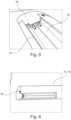
- FIG. 2illustrates an example of a blade 10 according to the present invention
- FIG. 3illustrates a cross-section through the blade 10 near the first end (root end);
- FIG. 4illustrates a cross-section of the blade 10 near the distal end 16 ;
- FIGS. 5 and 6illustrates a distal end 16 of a blade 10 where a light source 36 is arranged in the cavity 34 ;
- FIG. 7illustrates an end cap
- FIG. 1is illustrated an example of a ceiling mounted type fan.
- the particular fanis a high volume low speed type fan.
- Five blades 10are arranged attached to a motor 2 which causes the blades to rotate, thereby agitating the air.
- the fanis special in that a light-source is incorporated in the blades, where the light is emitted upwards.
- FIG. 2is illustrated an example of a blade 10 according to the present invention.
- a first end (root end) 12 of the blade 10are provided two apertures 14 . These apertures 14 are used for mounting the blade 10 to the motor 2 (rotor unit).
- a cavity 18In the other end (distal end) 16 of the blade 10 is provided a cavity 18 .
- the cavity 18is designed to house and hold a light source or a tray holding a light source (not illustrated)—as will be discussed below.
- the length of the blade 10may of course be designed according to the actual situation. Below the details of the blade will be discussed. From this description it is clear that the profile may be extruded. Consequently, when deciding on the length of the blade, it may be cut from the extruded length at any desired length. However, the internal strength must be calculated according to the ribs/walls internally in the blade's profile.
- FIG. 3is illustrated a cross-section through the blade 10 near the first end (root end) 12 .
- the blade's cross-section 12 ′ in FIG. 3comprises a cross-section of a first longitudinal chamber 20 .
- the blade's cross-section 12 ′ in FIG. 3comprises a second longitudinal chamber 30 , a third longitudinal chamber 40 and a fourth longitudinal chamber 50 .
- This first longitudinal chamber 20is designed to accommodate an electrical wire leading from the motor (rotor unit) or more correctly from the mounting disc (not disclosed) on the motor, which is rotated by the motor and transfers electricity to the blade ( 10 ).
- a second longitudinal chamber 30is designed to accommodate, in the first end 12 a transformer/ballast (not illustrated) for regulating the current to the light source. Between the first longitudinal chamber and the second longitudinal chamber is provided a rib/wall 22 , which provides strength in the longitudinal direction of the blade 10 . Like-wise, the second longitudinal chamber 20 is separated from a third longitudinal chamber 40 by a further wall/rib 32 . In the third longitudinal chamber 40 is provided means 42 , 44 in the shape of a mounting bracket suitable to engage the mounting disc of the motor unit. In this particular embodiment the means 42 , 44 is in the shape of two sets of flanges which are dimensioned to engage and embrace an engagement member of the mounting disc. Additionally an aperture 46 is provided, such that a fastening screw (not illustrated) may be inserted fastening the engagement member to the blade 10 .
- a fourth longitudinal chamber 50is provided adjacent the third longitudinal chamber 40 , where the third and fourth longitudinal chambers are separated by a rib/wall 52 .
- the fourth longitudinal chamber 50is designed to provide the blade with an overall aerodynamic cross-section.
- the curvature of the cross-sectionfacilitates that the in use lower surface 54 will urge air downwards when the blade is brought to rotate in the direction indicated by the arrow 60 .
- the distal or rear edge 56 of the blade 10is designed relatively sharp, as it will leave the air passing over and below the blade as it travels through the air with as little disturbance as possible—apart from urging air downwards. In this manner less noise is generated.
- the bladeis provided with a substantially flush and smooth outer surface.
- FIG. 4is illustrated a cross-section of the blade 10 near the distal end 16 .
- the first, third and fourth longitudinal chambersare exactly as described above with reference to the cross-section near the first end (root end)— FIG. 3 .
- the second longitudinal chamberis modified, by removing part of the surface thereby creating a cavity 34 .
- the cavityis designed to accommodate a light source (not illustrated) either directly or a light source placed in a tray, where the tray is designed to be accommodated in the cavity 34 .
- the cavity 34is open towards what in use will be upwards, but naturally the cavity may also be open downwards.
- FIGS. 5 and 6is illustrated a distal end 16 of a blade 10 where a light source 36 is arranged in the cavity 34 . Furthermore, an end cap 60 is arranged in the distal end.
- the end cap 60has extensions 62 (see FIG. 7 ) such that when these extensions are inserted into the end of the blade 10 , the end cap 60 is held in a position such that the end cap is smooth with the profile of the blade 10 , and at the same time retains the light source 36 or the light source tray (not illustrated) in the cavity 18 .
- the end capmay be mechanically fastened as illustrated by the screw 64 in FIG. 6 .
Landscapes
- Engineering & Computer Science (AREA)
- Mechanical Engineering (AREA)
- General Engineering & Computer Science (AREA)
- Structures Of Non-Positive Displacement Pumps (AREA)
Abstract
Description
- a. A first longitudinal chamber suitable to accommodate an electrical wire;
- b. A second longitudinal chamber, which second longitudinal chamber is suitable to accommodate:
- i. near the root end, a transformer unit
- ii. near the distal end, said light source
- c. A third longitudinal chamber suitable to accommodate:
- i. near the root end a mounting bracket, allowing the blade to be mounted to the ventilator's rotor unit;
- ii. near the distal end an endcap, said endcap having a cross-section corresponding to the cross-section of the blade, and where the endcap has a closed side and an opposing side having means for being attached to the blade, said means projecting into said third longitudinal chamber;
- d. A fourth longitudinal chamber allowing the blade to obtain the aerodynamic shape.
- a. a first longitudinal chamber suitable to accommodate an electrical wire;
- b. a second longitudinal chamber suitable to accommodate:
- i. near the root end, a transformer unit;
- ii. near the distal end, said light source;
- c. a third longitudinal chamber suitable to accommodate:
- i. near the root end, a mounting bracket, allowing the blade to be mounted to the motor or rotor unit;
- ii. near the distal end, an endcap having a cross-section corresponding to the cross-section of the blade, and where the endcap has a closed side and an opposing side having means for being attached to the blade, said means projecting into said third longitudinal chamber;
- d. A fourth longitudinal chamber allowing the blade to obtain the aerodynamic profile.
Claims (10)
Applications Claiming Priority (4)
| Application Number | Priority Date | Filing Date | Title |
|---|---|---|---|
| DKPA202170334 | 2021-06-28 | ||
| DKPA202170334 | 2021-06-28 | ||
| DK202170334 | 2021-06-28 | ||
| PCT/DK2022/050130WO2023274473A1 (en) | 2021-06-28 | 2022-06-16 | Blade construction |
Publications (2)
| Publication Number | Publication Date |
|---|---|
| US20240328430A1 US20240328430A1 (en) | 2024-10-03 |
| US12331753B2true US12331753B2 (en) | 2025-06-17 |
Family
ID=82458621
Family Applications (1)
| Application Number | Title | Priority Date | Filing Date |
|---|---|---|---|
| US18/575,211ActiveUS12331753B2 (en) | 2021-06-28 | 2022-06-16 | Blade construction |
Country Status (7)
| Country | Link |
|---|---|
| US (1) | US12331753B2 (en) |
| EP (1) | EP4363726A1 (en) |
| CN (1) | CN117597517A (en) |
| BR (1) | BR112023027430A2 (en) |
| CA (1) | CA3223440A1 (en) |
| MX (1) | MX2024000040A (en) |
| WO (1) | WO2023274473A1 (en) |
Citations (58)
| Publication number | Priority date | Publication date | Assignee | Title |
|---|---|---|---|---|
| US4422824A (en)* | 1982-03-29 | 1983-12-27 | Eisenhardt Jr Charles A | Germicidal ceiling fan blade |
| JPH09314137A (en) | 1996-05-29 | 1997-12-09 | Daikin Ind Ltd | Fluid processing device |
| US20020102161A1 (en) | 2001-01-26 | 2002-08-01 | Thorsten Nordhoff | Wind power generating system with an obstruction lighting or night marking device |
| US20030230477A1 (en) | 2002-06-14 | 2003-12-18 | Fink Ronald G. | Environmental air sterilization system |
| US20060130663A1 (en) | 2004-12-20 | 2006-06-22 | General Electric Company | System and method of air quality control for air-conditioning devices |
| US7252478B2 (en) | 2004-07-21 | 2007-08-07 | Delta T Corporation | Fan blade modifications |
| US7284960B2 (en) | 2004-07-21 | 2007-10-23 | Delta T Corporation | Fan blades |
| EP1870114A1 (en) | 2006-06-23 | 2007-12-26 | Global Engineering and Trade S.p.A. | Air purification device by means of photocatalytic reactions |
| US20090129974A1 (en) | 2007-08-02 | 2009-05-21 | Mcellen John J | Air quality enhancing ceiling paddle fan |
| USD607988S1 (en) | 2009-04-29 | 2010-01-12 | Delta T Corporation | Ceiling fan |
| USD612476S1 (en) | 2009-03-17 | 2010-03-23 | Haiku Design SDN. BHD. | Fan |
| USD614757S1 (en) | 2008-09-30 | 2010-04-27 | Haiku Design Sdn Bhd | Fan |
| US20100104461A1 (en) | 2008-10-29 | 2010-04-29 | Smith J Carey | Multi-Part Modular Airfoil Section and Method of Attachment Between Parts |
| KR20100053366A (en) | 2008-11-12 | 2010-05-20 | (주)선영에스티 | Rotary fan with photocatalytic function |
| US20110085908A1 (en) | 2009-10-13 | 2011-04-14 | Mark Pelshak | Modular fan blade with combined electrical and mechanical connection system |
| US7934907B2 (en) | 2004-07-21 | 2011-05-03 | Delta T Corporation | Cuffed fan blade modifications |
| CN202001939U (en) | 2011-01-06 | 2011-10-05 | 英飞特光电(杭州)有限公司 | LED (light-emitting diode) fan lamp |
| US8162613B2 (en) | 2007-03-01 | 2012-04-24 | Delta T Corporation | Angled airfoil extension for fan blade |
| KR20130012612A (en) | 2011-07-26 | 2013-02-05 | 엘지이노텍 주식회사 | Lighting module |
| USD690409S1 (en) | 2012-03-02 | 2013-09-24 | Delta T Corporation | Ceiling fan |
| US20130272879A1 (en) | 2012-04-11 | 2013-10-17 | Chin-Li Chen | Ceiling Fan |
| USD692120S1 (en) | 2012-03-02 | 2013-10-22 | Delta T Corporation | Ceiling fan with light |
| US8770949B2 (en) | 2008-09-04 | 2014-07-08 | Delta T Corporation | Ceiling fan |
| USD717935S1 (en) | 2013-06-17 | 2014-11-18 | Delta T Corporation | Ceiling fan |
| USD717936S1 (en) | 2014-02-27 | 2014-11-18 | Delta T Corporation | Blade tip |
| US20150009666A1 (en) | 2013-07-03 | 2015-01-08 | Cordelia Lighting, Inc. | Universal led light kit |
| USD723678S1 (en) | 2013-06-17 | 2015-03-03 | Delta T Corporation | Winglet for a ceiling fan |
| USD732657S1 (en) | 2014-02-27 | 2015-06-23 | Delta T Corporation | Winglet |
| CN105526564A (en) | 2016-01-29 | 2016-04-27 | 太仓世源金属制品有限公司 | Mounting seat allowing electronic product to be embedded in |
| US9458859B2 (en) | 2007-10-10 | 2016-10-04 | Delta T Corporation | Ceiling fan system with brushless motor |
| US20160290357A1 (en) | 2015-03-31 | 2016-10-06 | Assa Abloy Entrance Systems Ab | Fan blades and associated blade tips |
| USD770027S1 (en) | 2015-06-30 | 2016-10-25 | Delta T Corporation | Fan |
| WO2016200047A1 (en) | 2015-06-10 | 2016-12-15 | 구기승 | Ceiling-mounted multifunctional fan comprising polluted air sterilization and purification member |
| US9587518B2 (en) | 2012-03-20 | 2017-03-07 | Delta T Corporation | Ball and socket fan mount |
| USD781252S1 (en) | 2015-08-27 | 2017-03-14 | Delta T Corporation | Control device |
| USD783883S1 (en) | 2016-01-04 | 2017-04-11 | Delta T Corporation | Light fixture |
| US9664194B2 (en) | 2013-05-24 | 2017-05-30 | Delta T Corporation | Ceiling fan with moisture protection features |
| USD797917S1 (en) | 2015-08-17 | 2017-09-19 | Delta T Corporation | Fan with light |
| US9900955B1 (en) | 2016-01-06 | 2018-02-20 | Delta T Corporation | Luminaire having an adjustable color temperature of emitted light and related methods |
| USD812006S1 (en) | 2015-10-09 | 2018-03-06 | Delta T Corporation | Fan motor |
| CN207333242U (en) | 2017-08-28 | 2018-05-08 | 江门市新会区藤森五金电器厂有限公司 | A kind of novel environment friendly mosquito-killing ceiling fan assembly |
| CN108278215A (en) | 2018-03-22 | 2018-07-13 | 浙江开勒环保设备有限公司 | A kind of industrial air-purification type environment-protecting ceiling fan |
| CN108457879A (en) | 2018-03-22 | 2018-08-28 | 浙江开勒环保设备有限公司 | A kind of industrial environmentally friendly electric fan |
| US10154565B1 (en) | 2016-06-28 | 2018-12-11 | Delta T, Llc | Lighting system with ambient light compensation |
| CN109209949A (en) | 2018-10-25 | 2019-01-15 | 江门市旭照金属线材有限公司 | A kind of ceiling fan being made of ring of light illumination rotation |
| US20190072107A1 (en)* | 2017-09-04 | 2019-03-07 | Sunonwealth Electric Machine Industry Co., Ltd. | Flow Guiding Device for a Fan |
| US20190072288A1 (en) | 2016-12-28 | 2019-03-07 | Darrin Niemiec | Ceiling tile with built-in air flow mechanism and uv air purifying device |
| US20190162433A1 (en) | 2012-10-31 | 2019-05-30 | Delta T, Llc | Integrated thermal comfort control system utilizing circulating fans |
| US20190298869A1 (en) | 2018-03-29 | 2019-10-03 | Bridgeport Magnetics Group, Inc. | Apparatus And Method For Ultraviolet Light Surface Disinfection |
| CN110685935A (en) | 2018-07-06 | 2020-01-14 | 金士盾科技股份有限公司 | Ceiling fan forced cooling structure |
| US20200224897A1 (en) | 2019-01-15 | 2020-07-16 | Home Depot Product Authority, Llc | Misting fan |
| US20200263700A1 (en) | 2019-02-19 | 2020-08-20 | Mao-Tu Lee | Industrial ceiling fan structure |
| CN111617271A (en) | 2020-05-19 | 2020-09-04 | 广州市波电电子科技有限公司 | Optical system applied to disinfection and sterilization device |
| CN211778100U (en) | 2020-03-10 | 2020-10-27 | 武汉奇亚环境科技有限公司 | Multifunctional ultraviolet disinfection ceiling fan |
| US20210353820A1 (en) | 2020-05-15 | 2021-11-18 | Delta T, Llc | Fan system for improving indoor air quality and related methods |
| US20210388844A1 (en) | 2020-06-16 | 2021-12-16 | Delta T, Llc | Ceiling fan with germicidal capabilities |
| EP3936159A1 (en) | 2020-07-10 | 2022-01-12 | Sood, Seth, Khatri & Chaudhary LLC | Ultraviolet pathogen disinfection system |
| US20220133941A1 (en) | 2020-10-30 | 2022-05-05 | Nordicco ApS | Fan assembly with ultraviolet disinfection |
- 2022
- 2022-06-16WOPCT/DK2022/050130patent/WO2023274473A1/ennot_activeCeased
- 2022-06-16BRBR112023027430Apatent/BR112023027430A2/enunknown
- 2022-06-16EPEP22738542.4Apatent/EP4363726A1/enactivePending
- 2022-06-16CNCN202280046379.2Apatent/CN117597517A/enactivePending
- 2022-06-16USUS18/575,211patent/US12331753B2/enactiveActive
- 2022-06-16CACA3223440Apatent/CA3223440A1/enactivePending
- 2022-06-16MXMX2024000040Apatent/MX2024000040A/enunknown
Patent Citations (70)
| Publication number | Priority date | Publication date | Assignee | Title |
|---|---|---|---|---|
| US4422824A (en)* | 1982-03-29 | 1983-12-27 | Eisenhardt Jr Charles A | Germicidal ceiling fan blade |
| JPH09314137A (en) | 1996-05-29 | 1997-12-09 | Daikin Ind Ltd | Fluid processing device |
| US20020102161A1 (en) | 2001-01-26 | 2002-08-01 | Thorsten Nordhoff | Wind power generating system with an obstruction lighting or night marking device |
| US20030230477A1 (en) | 2002-06-14 | 2003-12-18 | Fink Ronald G. | Environmental air sterilization system |
| US7252478B2 (en) | 2004-07-21 | 2007-08-07 | Delta T Corporation | Fan blade modifications |
| US7284960B2 (en) | 2004-07-21 | 2007-10-23 | Delta T Corporation | Fan blades |
| US7654798B2 (en) | 2004-07-21 | 2010-02-02 | Delta T Corporation | Fan blade modifications |
| US7934907B2 (en) | 2004-07-21 | 2011-05-03 | Delta T Corporation | Cuffed fan blade modifications |
| US20060130663A1 (en) | 2004-12-20 | 2006-06-22 | General Electric Company | System and method of air quality control for air-conditioning devices |
| EP1870114A1 (en) | 2006-06-23 | 2007-12-26 | Global Engineering and Trade S.p.A. | Air purification device by means of photocatalytic reactions |
| US8821126B2 (en) | 2007-03-01 | 2014-09-02 | Delta T Corporation | Angled airfoil extension for fan blade |
| US8162613B2 (en) | 2007-03-01 | 2012-04-24 | Delta T Corporation | Angled airfoil extension for fan blade |
| US20090129974A1 (en) | 2007-08-02 | 2009-05-21 | Mcellen John J | Air quality enhancing ceiling paddle fan |
| US9458859B2 (en) | 2007-10-10 | 2016-10-04 | Delta T Corporation | Ceiling fan system with brushless motor |
| US11268528B2 (en) | 2007-10-10 | 2022-03-08 | Delta T, Llc | Ceiling fan system with brushless motor |
| US20170089346A1 (en) | 2007-10-10 | 2017-03-30 | Richard A. Oleson | Ceiling fan system with brushless motor |
| US8770949B2 (en) | 2008-09-04 | 2014-07-08 | Delta T Corporation | Ceiling fan |
| USD614757S1 (en) | 2008-09-30 | 2010-04-27 | Haiku Design Sdn Bhd | Fan |
| US20100104461A1 (en) | 2008-10-29 | 2010-04-29 | Smith J Carey | Multi-Part Modular Airfoil Section and Method of Attachment Between Parts |
| KR20100053366A (en) | 2008-11-12 | 2010-05-20 | (주)선영에스티 | Rotary fan with photocatalytic function |
| USD612476S1 (en) | 2009-03-17 | 2010-03-23 | Haiku Design SDN. BHD. | Fan |
| USD607988S1 (en) | 2009-04-29 | 2010-01-12 | Delta T Corporation | Ceiling fan |
| US20110085908A1 (en) | 2009-10-13 | 2011-04-14 | Mark Pelshak | Modular fan blade with combined electrical and mechanical connection system |
| CN202001939U (en) | 2011-01-06 | 2011-10-05 | 英飞特光电(杭州)有限公司 | LED (light-emitting diode) fan lamp |
| KR20130012612A (en) | 2011-07-26 | 2013-02-05 | 엘지이노텍 주식회사 | Lighting module |
| USD690409S1 (en) | 2012-03-02 | 2013-09-24 | Delta T Corporation | Ceiling fan |
| USD692120S1 (en) | 2012-03-02 | 2013-10-22 | Delta T Corporation | Ceiling fan with light |
| US9587518B2 (en) | 2012-03-20 | 2017-03-07 | Delta T Corporation | Ball and socket fan mount |
| US20130272879A1 (en) | 2012-04-11 | 2013-10-17 | Chin-Li Chen | Ceiling Fan |
| US20190162433A1 (en) | 2012-10-31 | 2019-05-30 | Delta T, Llc | Integrated thermal comfort control system utilizing circulating fans |
| US9664194B2 (en) | 2013-05-24 | 2017-05-30 | Delta T Corporation | Ceiling fan with moisture protection features |
| USD717935S1 (en) | 2013-06-17 | 2014-11-18 | Delta T Corporation | Ceiling fan |
| USD723678S1 (en) | 2013-06-17 | 2015-03-03 | Delta T Corporation | Winglet for a ceiling fan |
| US20150009666A1 (en) | 2013-07-03 | 2015-01-08 | Cordelia Lighting, Inc. | Universal led light kit |
| USD732657S1 (en) | 2014-02-27 | 2015-06-23 | Delta T Corporation | Winglet |
| USD717936S1 (en) | 2014-02-27 | 2014-11-18 | Delta T Corporation | Blade tip |
| US20160290357A1 (en) | 2015-03-31 | 2016-10-06 | Assa Abloy Entrance Systems Ab | Fan blades and associated blade tips |
| CN106247443A (en) | 2015-06-10 | 2016-12-21 | 丘冀昇 | There is contaminated air sterilization and the ceiling adhesion type complex function fan of purification portion |
| WO2016200047A1 (en) | 2015-06-10 | 2016-12-15 | 구기승 | Ceiling-mounted multifunctional fan comprising polluted air sterilization and purification member |
| USD879282S1 (en) | 2015-06-30 | 2020-03-24 | Delta T, Llc | Fan |
| USD808004S1 (en) | 2015-06-30 | 2018-01-16 | Delta T Corporation | Fan |
| USD770027S1 (en) | 2015-06-30 | 2016-10-25 | Delta T Corporation | Fan |
| USD797917S1 (en) | 2015-08-17 | 2017-09-19 | Delta T Corporation | Fan with light |
| USD810702S1 (en) | 2015-08-27 | 2018-02-20 | Delta T Corporation | Control device |
| USD781252S1 (en) | 2015-08-27 | 2017-03-14 | Delta T Corporation | Control device |
| USD812006S1 (en) | 2015-10-09 | 2018-03-06 | Delta T Corporation | Fan motor |
| USD783883S1 (en) | 2016-01-04 | 2017-04-11 | Delta T Corporation | Light fixture |
| US9900955B1 (en) | 2016-01-06 | 2018-02-20 | Delta T Corporation | Luminaire having an adjustable color temperature of emitted light and related methods |
| CN105526564A (en) | 2016-01-29 | 2016-04-27 | 太仓世源金属制品有限公司 | Mounting seat allowing electronic product to be embedded in |
| US10154565B1 (en) | 2016-06-28 | 2018-12-11 | Delta T, Llc | Lighting system with ambient light compensation |
| US20190072288A1 (en) | 2016-12-28 | 2019-03-07 | Darrin Niemiec | Ceiling tile with built-in air flow mechanism and uv air purifying device |
| CN207333242U (en) | 2017-08-28 | 2018-05-08 | 江门市新会区藤森五金电器厂有限公司 | A kind of novel environment friendly mosquito-killing ceiling fan assembly |
| US20190072107A1 (en)* | 2017-09-04 | 2019-03-07 | Sunonwealth Electric Machine Industry Co., Ltd. | Flow Guiding Device for a Fan |
| CN108457879A (en) | 2018-03-22 | 2018-08-28 | 浙江开勒环保设备有限公司 | A kind of industrial environmentally friendly electric fan |
| CN108278215A (en) | 2018-03-22 | 2018-07-13 | 浙江开勒环保设备有限公司 | A kind of industrial air-purification type environment-protecting ceiling fan |
| US20190298869A1 (en) | 2018-03-29 | 2019-10-03 | Bridgeport Magnetics Group, Inc. | Apparatus And Method For Ultraviolet Light Surface Disinfection |
| CN110685935A (en) | 2018-07-06 | 2020-01-14 | 金士盾科技股份有限公司 | Ceiling fan forced cooling structure |
| CN109209949A (en) | 2018-10-25 | 2019-01-15 | 江门市旭照金属线材有限公司 | A kind of ceiling fan being made of ring of light illumination rotation |
| US20200224897A1 (en) | 2019-01-15 | 2020-07-16 | Home Depot Product Authority, Llc | Misting fan |
| US20200263700A1 (en) | 2019-02-19 | 2020-08-20 | Mao-Tu Lee | Industrial ceiling fan structure |
| CN211778100U (en) | 2020-03-10 | 2020-10-27 | 武汉奇亚环境科技有限公司 | Multifunctional ultraviolet disinfection ceiling fan |
| US20210353820A1 (en) | 2020-05-15 | 2021-11-18 | Delta T, Llc | Fan system for improving indoor air quality and related methods |
| CN111617271A (en) | 2020-05-19 | 2020-09-04 | 广州市波电电子科技有限公司 | Optical system applied to disinfection and sterilization device |
| US20210388844A1 (en) | 2020-06-16 | 2021-12-16 | Delta T, Llc | Ceiling fan with germicidal capabilities |
| US20210388841A1 (en) | 2020-06-16 | 2021-12-16 | Delta T, Llc | Ceiling fan with germicidal capabilities |
| US20210388842A1 (en) | 2020-06-16 | 2021-12-16 | Delta T, Llc | Ceiling fan with germicidal capabilities |
| WO2021257658A1 (en) | 2020-06-16 | 2021-12-23 | Delta T, Llc | Ceiling fan with germicidal capabilities |
| US20210388843A1 (en) | 2020-06-16 | 2021-12-16 | Delta T, Llc | Ceiling fan with germicidal capabilities |
| EP3936159A1 (en) | 2020-07-10 | 2022-01-12 | Sood, Seth, Khatri & Chaudhary LLC | Ultraviolet pathogen disinfection system |
| US20220133941A1 (en) | 2020-10-30 | 2022-05-05 | Nordicco ApS | Fan assembly with ultraviolet disinfection |
Non-Patent Citations (7)
| Title |
|---|
| Danish Search Report for DK Application No. PA 2021 70311 mailed Nov. 22, 2021 (4 pages). |
| Danish Search Report for DK Application No. PA 2021 70334 mailed Dec. 1, 2021 (4 pages). |
| Dannish Search Report for DK Application No. PA 2020 70721 mailed Mar. 13, 2021 (4 pages). |
| International Search Report and Written Opinion for PCT/DK2021/050319 mailed Feb. 2, 2022. |
| International Search Report and Written Opinion for PCT/DK2022/050127 mailed Sep. 21, 2022. |
| International Search Report and Written Opinion for PCT/DK2022/050130 (Sep. 13. 2022). |
| Office Action issued in Danish Patent Application No. PA 2021 70334 (Dec. 27, 2021). |
Also Published As
| Publication number | Publication date |
|---|---|
| US20240328430A1 (en) | 2024-10-03 |
| CA3223440A1 (en) | 2023-01-05 |
| EP4363726A1 (en) | 2024-05-08 |
| CN117597517A (en) | 2024-02-23 |
| WO2023274473A1 (en) | 2023-01-05 |
| MX2024000040A (en) | 2024-02-21 |
| BR112023027430A2 (en) | 2024-03-12 |
Similar Documents
| Publication | Publication Date | Title |
|---|---|---|
| US7384168B2 (en) | Light fixture having air ducts | |
| US5440459A (en) | Ceiling fan having a light assembly | |
| US10823375B2 (en) | Light cover assembling structure of a ceiling fan | |
| US20160054015A1 (en) | 70 cfm bath ventilation fans with flush mount lights and motor beneath blower wheel | |
| US20070247854A1 (en) | Ceiling fan | |
| CN106246562A (en) | Band illumination ceiling embedded type ventilation fan | |
| DE602005014137D1 (en) | VENTILATION SYSTEM FOR MOTOR VEHICLES | |
| US12331753B2 (en) | Blade construction | |
| US20240011505A1 (en) | Ceiling fan hanger assembly | |
| US20210355948A1 (en) | Ceiling fan with air cleaner | |
| US20100110702A1 (en) | Compact Fluorescent Lamp High Bay Luminaire | |
| JPH0718580B2 (en) | Ventilation fan for pipes | |
| CN216589275U (en) | Fan and fan lamp | |
| JP4717469B2 (en) | Negative ion generator | |
| US20190211984A1 (en) | Light assembly with pass-through controls | |
| CN220929707U (en) | Exhaust fan capable of replacing light source | |
| JP3220465U (en) | Lighting device | |
| KR200379928Y1 (en) | ventilating fan which has a lighting function | |
| JP2018003771A (en) | Air blower with lighting function | |
| CN108488695B (en) | wall lamp | |
| KR200244573Y1 (en) | Lampshade having a changing air function | |
| CN216715959U (en) | A Bamboo-shaped Lamp With Diverse Combination Installation | |
| CN216306277U (en) | Simple to operate's fan lamp | |
| CN223227529U (en) | Integrated fan lamp | |
| CN219366355U (en) | Fan lamp |
Legal Events
| Date | Code | Title | Description |
|---|---|---|---|
| FEPP | Fee payment procedure | Free format text:ENTITY STATUS SET TO UNDISCOUNTED (ORIGINAL EVENT CODE: BIG.); ENTITY STATUS OF PATENT OWNER: LARGE ENTITY | |
| FEPP | Fee payment procedure | Free format text:ENTITY STATUS SET TO SMALL (ORIGINAL EVENT CODE: SMAL); ENTITY STATUS OF PATENT OWNER: LARGE ENTITY | |
| AS | Assignment | Owner name:NORDICCO A/S, DENMARK Free format text:ASSIGNMENT OF ASSIGNORS INTEREST;ASSIGNORS:THOMSEN, DENNIS;HERMANSEN, JESPER;REEL/FRAME:066353/0043 Effective date:20240112 | |
| STPP | Information on status: patent application and granting procedure in general | Free format text:NON FINAL ACTION MAILED | |
| STPP | Information on status: patent application and granting procedure in general | Free format text:RESPONSE TO NON-FINAL OFFICE ACTION ENTERED AND FORWARDED TO EXAMINER | |
| STPP | Information on status: patent application and granting procedure in general | Free format text:NOTICE OF ALLOWANCE MAILED -- APPLICATION RECEIVED IN OFFICE OF PUBLICATIONS | |
| FEPP | Fee payment procedure | Free format text:ENTITY STATUS SET TO UNDISCOUNTED (ORIGINAL EVENT CODE: BIG.); ENTITY STATUS OF PATENT OWNER: LARGE ENTITY | |
| STCF | Information on status: patent grant | Free format text:PATENTED CASE |