US12330211B2 - Multi-diameter wire feeder - Google Patents
Multi-diameter wire feederDownload PDFInfo
- Publication number
- US12330211B2 US12330211B2US17/098,564US202017098564AUS12330211B2US 12330211 B2US12330211 B2US 12330211B2US 202017098564 AUS202017098564 AUS 202017098564AUS 12330211 B2US12330211 B2US 12330211B2
- Authority
- US
- United States
- Prior art keywords
- wire
- groove
- support
- feedstock
- driver roller
- Prior art date
- Legal status (The legal status is an assumption and is not a legal conclusion. Google has not performed a legal analysis and makes no representation as to the accuracy of the status listed.)
- Active, expires
Links
Images


Classifications
- B—PERFORMING OPERATIONS; TRANSPORTING
- B29—WORKING OF PLASTICS; WORKING OF SUBSTANCES IN A PLASTIC STATE IN GENERAL
- B29C—SHAPING OR JOINING OF PLASTICS; SHAPING OF MATERIAL IN A PLASTIC STATE, NOT OTHERWISE PROVIDED FOR; AFTER-TREATMENT OF THE SHAPED PRODUCTS, e.g. REPAIRING
- B29C64/00—Additive manufacturing, i.e. manufacturing of three-dimensional [3D] objects by additive deposition, additive agglomeration or additive layering, e.g. by 3D printing, stereolithography or selective laser sintering
- B29C64/10—Processes of additive manufacturing
- B29C64/106—Processes of additive manufacturing using only liquids or viscous materials, e.g. depositing a continuous bead of viscous material
- B29C64/118—Processes of additive manufacturing using only liquids or viscous materials, e.g. depositing a continuous bead of viscous material using filamentary material being melted, e.g. fused deposition modelling [FDM]
- B—PERFORMING OPERATIONS; TRANSPORTING
- B22—CASTING; POWDER METALLURGY
- B22D—CASTING OF METALS; CASTING OF OTHER SUBSTANCES BY THE SAME PROCESSES OR DEVICES
- B22D23/00—Casting processes not provided for in groups B22D1/00 - B22D21/00
- B22D23/003—Moulding by spraying metal on a surface
- B—PERFORMING OPERATIONS; TRANSPORTING
- B23—MACHINE TOOLS; METAL-WORKING NOT OTHERWISE PROVIDED FOR
- B23K—SOLDERING OR UNSOLDERING; WELDING; CLADDING OR PLATING BY SOLDERING OR WELDING; CUTTING BY APPLYING HEAT LOCALLY, e.g. FLAME CUTTING; WORKING BY LASER BEAM
- B23K35/00—Rods, electrodes, materials, or media, for use in soldering, welding, or cutting
- B23K35/02—Rods, electrodes, materials, or media, for use in soldering, welding, or cutting characterised by mechanical features, e.g. shape
- B23K35/0205—Non-consumable electrodes; C-electrodes
- B—PERFORMING OPERATIONS; TRANSPORTING
- B29—WORKING OF PLASTICS; WORKING OF SUBSTANCES IN A PLASTIC STATE IN GENERAL
- B29C—SHAPING OR JOINING OF PLASTICS; SHAPING OF MATERIAL IN A PLASTIC STATE, NOT OTHERWISE PROVIDED FOR; AFTER-TREATMENT OF THE SHAPED PRODUCTS, e.g. REPAIRING
- B29C64/00—Additive manufacturing, i.e. manufacturing of three-dimensional [3D] objects by additive deposition, additive agglomeration or additive layering, e.g. by 3D printing, stereolithography or selective laser sintering
- B29C64/20—Apparatus for additive manufacturing; Details thereof or accessories therefor
- B29C64/205—Means for applying layers
- B29C64/209—Heads; Nozzles
- B—PERFORMING OPERATIONS; TRANSPORTING
- B33—ADDITIVE MANUFACTURING TECHNOLOGY
- B33Y—ADDITIVE MANUFACTURING, i.e. MANUFACTURING OF THREE-DIMENSIONAL [3-D] OBJECTS BY ADDITIVE DEPOSITION, ADDITIVE AGGLOMERATION OR ADDITIVE LAYERING, e.g. BY 3-D PRINTING, STEREOLITHOGRAPHY OR SELECTIVE LASER SINTERING
- B33Y10/00—Processes of additive manufacturing
- B—PERFORMING OPERATIONS; TRANSPORTING
- B33—ADDITIVE MANUFACTURING TECHNOLOGY
- B33Y—ADDITIVE MANUFACTURING, i.e. MANUFACTURING OF THREE-DIMENSIONAL [3-D] OBJECTS BY ADDITIVE DEPOSITION, ADDITIVE AGGLOMERATION OR ADDITIVE LAYERING, e.g. BY 3-D PRINTING, STEREOLITHOGRAPHY OR SELECTIVE LASER SINTERING
- B33Y30/00—Apparatus for additive manufacturing; Details thereof or accessories therefor
- B—PERFORMING OPERATIONS; TRANSPORTING
- B22—CASTING; POWDER METALLURGY
- B22F—WORKING METALLIC POWDER; MANUFACTURE OF ARTICLES FROM METALLIC POWDER; MAKING METALLIC POWDER; APPARATUS OR DEVICES SPECIALLY ADAPTED FOR METALLIC POWDER
- B22F2999/00—Aspects linked to processes or compositions used in powder metallurgy
- B—PERFORMING OPERATIONS; TRANSPORTING
- B23—MACHINE TOOLS; METAL-WORKING NOT OTHERWISE PROVIDED FOR
- B23K—SOLDERING OR UNSOLDERING; WELDING; CLADDING OR PLATING BY SOLDERING OR WELDING; CUTTING BY APPLYING HEAT LOCALLY, e.g. FLAME CUTTING; WORKING BY LASER BEAM
- B23K35/00—Rods, electrodes, materials, or media, for use in soldering, welding, or cutting
- Y—GENERAL TAGGING OF NEW TECHNOLOGICAL DEVELOPMENTS; GENERAL TAGGING OF CROSS-SECTIONAL TECHNOLOGIES SPANNING OVER SEVERAL SECTIONS OF THE IPC; TECHNICAL SUBJECTS COVERED BY FORMER USPC CROSS-REFERENCE ART COLLECTIONS [XRACs] AND DIGESTS
- Y02—TECHNOLOGIES OR APPLICATIONS FOR MITIGATION OR ADAPTATION AGAINST CLIMATE CHANGE
- Y02P—CLIMATE CHANGE MITIGATION TECHNOLOGIES IN THE PRODUCTION OR PROCESSING OF GOODS
- Y02P10/00—Technologies related to metal processing
- Y02P10/25—Process efficiency
Definitions
- additive manufacturing techniquessuch as three-dimensional (3D) printing are rapidly being adopted as useful techniques for a host of different applications, including rapid prototyping and the fabrication of specialty components.
- 3D printingadditive manufacturing processes have utilized polymeric materials in which polymeric material is pulled from a source into a nozzle, then melted, and subsequently deposited into a specified pattern in a layer-by-layer fashion to form a 3D object.
- Existing technologies for the additive manufacture of metal structuresmay be performed by laser sintering or adhesive bonding followed by sintering.
- Such sintering technologiesmay use a bed of metal powder in a build area, and the powder particles are selectively joined to one another to form the desired pattern.
- more metal powdermay be spread over the first layer, and powder particles may be joined to the previous layer in accordance with a pattern for that layer.
- the processmay continue to build the desired structure in a layer-by-layer manner.
- laser sinteringmay use a high power laser as the source of heat to fuse particles. Lasers have many safety risks, especially at the powers required for fusing metals.
- Adhesive bondingmay use glue to join adjacent powder particles instead of directly fusing the particles by laser energy, but the process may otherwise be similar.
- Gluemay be selectively sprayed to form a pattern, and powder may be added in a layer-by-layer manner to form the structure.
- the structuremay be removed from the powder bed and placed in a furnace to sinter the bonded metal powders.
- heat to liquefy the metalmay be derived from plasma or electric arc.
- the molten metalmay then be sprayed in a pattern desired to form a structure by building layers as the metal cools.
- metal powdermay be expensive to produce and may be more expensive than other feedstock (e.g., a wire) formed from the same material for the same amount of material.
- feedstocke.g., a wire
- Metal powdersmay be difficult and dangerous to handle. For example, metal powder that is spilled may form dust in the air that is dangerous to inhale, and such dust may even be an explosion risk.
- the amount of powder required for conventional additive manufacturing technologiesmay be many times greater than that required to make the 3D object, as the entire build area may be filled with powder.
- the present disclosureprovides systems and methods for 3D printing using a feedstock (e.g., wire) that may help avoid various disadvantages of other 3D printing methods and systems.
- Methods and systems of the present disclosureenable a feedstock to be directed from a source of the feedstock to a print head (e.g., including a guide) for deposition in a manner that reduces stress(es) imposed on the feedstock. This may advantageously increase the longevity of various components of systems of the present disclosure.
- rollerse.g., driver rollers
- a wiremay be directed from a source (e.g., a wire spool) to a print head for deposition in a manner that reduces stress(es) on the wire while it is directed from the source to the print head.
- a sourcee.g., a wire spool
- Such rollersmay be used to direct multiple wires (e.g., wires having different sizes, diameters or cross-sectional dimensions) or wires of different materials during printing.
- the present disclosurealso provides improved grooves on the rollers that may permit a wire to be directed from a source to a print head for deposition in a manner that reduces stress(es) on the wire or portions of the driver rollers that are in contact with the wire while it is directed from the source to the print head.
- the present disclosureprovides a system for printing a three-dimensional (3D) object, comprising: (1) a wire source configured to hold a wire, which wire is usable for printing the 3D object; (2) a print head comprising a guide, which guide directs the wire from the wire source towards and in contact with a support or at least a portion of the 3D object adjacent to the support; (3) a driver roller, which the driver roller comprising a groove that is configured to (i) accept at least a portion of the wire and (ii) direct the at least the portion of the wire towards the guide; (4) a power source in electrical communication with the wire and the support, wherein the power source is configured to supply electrical current from the guide through the wire and to the support, or vice versa, during printing of the 3D object; and (5) a controller in electrical communication with the power source, wherein the controller is configured to direct the power source to supply the electrical current from the guide through the wire and to the support, or vice versa, during printing of the 3D object under conditions sufficient to melt the wire
- the driver rollercomprises at least one additional groove adjacent to the groove. In some embodiments, the driver roller comprises a position adjusting mechanism to move the driver roller into alignment with the wire. In some embodiments, the position adjusting mechanism is automated. In some embodiments, the positioning adjusting mechanism automatically moves the driver roller into alignment with the wire.
- the driver rolleris connected to an electric motor for rotating the driver roller at a plurality of operating speeds.
- the systemfurther comprises a motor controller operatively coupled to the electric motor.
- the motor controlleris configured to accelerate, decelerate, maintain at a given speed of the plurality of operating speeds, or control direction of rotation of the electric motor.
- the grooveis substantially U-shaped. In some embodiments, a radius of curvature of the groove is substantially the same as a radius of curvature of the wire. In some embodiments, the groove has a radius of curvature that deviates from a radius of curvature of the wire by at most 5%. In some embodiments, the groove has a radius of curvature that deviates from a radius of curvature of the wire by at most 50%.
- the groovehas a concave shape corresponding to at least a vertex section of an ellipsoid or a vesica piscis.
- the concave shape of the groovehas two sides converging at a tip of the vertex section.
- the two sideshave a substantially identical radius of curvature that deviates from a radius of curvature of the wire by at most 5%.
- the two sideshave a substantially identical radius of curvature that deviates from a radius of curvature of the wire by at most 50%.
- the two sides of the grooveis a continuation of at least two concave curves.
- an inner curve of the at least two concave curves that is closer to a rotational axis of the driver rollerhas a smaller radius of curvature than an adjacent outer curve of the at least two concave curves.
- the systemfurther comprises an assembly for directing the wire towards the guide.
- the assemblycomprises the driver roller and an additional roller.
- the additional rolleris configured to (i) contact at least a portion of the wire and (ii) direct the at least the portion of the wire into the groove of the driver roller of the assembly.
- the systemfurther comprises a wire merger.
- the wire mergercomprises at least one entry orifice for receiving the wire from the assembly and an exit orifice for directing the wire towards the guide.
- the assemblypushes the wire from the wire source towards the wire merger.
- the assemblypulls the wire along a direction away from the wire merger towards the guide.
- the systemfurther comprises a conduit for providing a continuous passageway for the wire from the assembly to the at least one entry orifice of the wire merger.
- the conduitis a flexible tube.
- the systemfurther comprises a buffer idler disposed between the wire source and the assembly.
- the buffer idleris configured to (i) contact at least a portion of the wire and (ii) direct the at least the portion of the wire towards the assembly.
- the wire mergercomprises a converging configuration to provide a path for the wire from the at least one entry orifice to the exit orifice. In some embodiments, the converging configuration of the wire merger directs the wire from the at least one entry orifice into the exit orifice.
- the systemfurther comprises at least one additional wire source to hold at least one additional wire.
- the at least one additional wireis usable for the printing the 3D object.
- the guide of the print headcomprises an opening. In some embodiments, the guide of the print head is a tip.
- the supportholds the at least the portion of the 3D object during the printing. In some embodiments, the support is a platform.
- the present disclosureprovides a method for printing a three-dimensional (3D) object, comprising: (a) activating a 3D printing system, comprising: (i) a wire source configured to hold a wire, which wire is usable for the printing the 3D object; (ii) a print head comprising a guide, which guide directs the wire from the wire source towards and in contact with a support or at least a portion of the 3D object adjacent to the support; (iii) a driver roller, which the driver roller comprising a groove that is configured to (i) accept at least a portion of the wire and (ii) direct the at least the portion of the wire towards the guide; and (iv) a power source in electrical communication with the wire and the support, wherein the power source is configured to supply electrical current from the guide through the wire and to the support during the printing; (b) using the driver roller to direct the at least the portion of the wire towards the guide; and (c) directing the power source to supply the electrical current from the guide through the wire and
- the methodfurther comprises detecting when the wire is in contact with the support or the at least the portion of the 3D object adjacent to the support. In some embodiments, the method further comprises directing the power source to supply the electrical current from the guide through the wire and to the support or the at least the portion of the 3D object adjacent to the support, or vice versa, when the wire is detected to be in contact with the support or the at least the portion of the 3D object.
- the methodfurther comprises adjusting a force of contact between the wire and the support or the at least the portion of the 3D object adjacent to the support.
- the methodfurther comprises activating an electric motor connected to the driver roller. In some embodiments, the method further comprises accelerating, decelerating, maintaining at a given speed of a plurality of operating speeds, or controlling direction of rotation of the electric motor.
- the driver rollercomprises at least one additional groove adjacent to the groove. In some embodiments, the driver roller comprises a position adjusting mechanism to move the driver roller into alignment with the wire. In some embodiments, the position adjusting mechanism is automated. In some embodiments, the positioning adjusting mechanism automatically moves the driver roller into alignment with the wire.
- the driver rolleris connected to an electric motor for rotating the driver roller at a plurality of operating speeds.
- the electric motoris operatively coupled to a motor controller.
- the motor controlleris configured to accelerate, decelerate, maintain at a given speed of the plurality of operating speeds, or control direction of rotation of the electric motor.
- the grooveis substantially U-shaped. In some embodiments, a radius of curvature of the groove is substantially the same as a radius of curvature of the wire. In some embodiments, the groove has a radius of curvature that deviates from a radius of curvature of the wire by at most 5%. In some embodiments, the groove has a radius of curvature that deviates from a radius of curvature of the wire by at most 50%.
- the groovehas a concave shape corresponding to at least a vertex section of an ellipsoid or a vesica piscis.
- the concave shape of the groovehas two sides converging at a tip of the vertex section.
- the two sideshave a substantially identical radius of curvature that deviates from a radius of curvature of the wire by at most 5%.
- the two sides of the grooveis a continuation of at least two concave curves.
- an inner curve of the at least two concave curves that is closer to a rotational axis of the driver rollerhas a smaller radius of curvature than an adjacent outer curve of the at least two concave curves.
- the methodfurther comprises using an assembly for directing the wire towards the guide.
- the assemblycomprises the driver roller and an additional roller.
- the additional rolleris configured to (i) contact at least a portion of the wire and (ii) direct the at least the portion of the wire into the groove of the driver roller of the assembly.
- the 3D printing systemfurther comprises a wire merger.
- the wire mergercomprises at least one entry orifice for receiving the wire from the assembly and an exit orifice for directing the wire towards the guide.
- the assemblypushes the wire from the wire source towards the wire merger.
- the assemblypulls the wire along a direction away from the wire merger towards the guide.
- the 3D printing systemfurther comprises a conduit for providing a continuous passageway for the wire from the assembly to the at least one entry orifice of the wire merger.
- the conduitis a flexible tube.
- the 3D printing systemfurther comprises a buffer idler disposed between the wire source and the assembly.
- the buffer idleris configured to (i) contact at least a portion of the wire and (ii) direct the at least the portion of the wire towards the assembly.
- the wire mergercomprises a converging configuration to provide a path for the wire from the at least one entry orifice to the exit orifice. In some embodiments, the converging configuration of the wire merger directs the wire from the at least one entry orifice into the exit orifice.
- the 3D printing systemfurther comprises at least one additional wire source to hold at least one additional wire.
- the at least one additional wireis usable for the printing the 3D object.
- the guide of the print headcomprises an opening. In some embodiments, the guide of the print head is a tip. In some embodiments, the support holds the at least the portion of the 3D object during the printing.
- the present disclosureprovides a system for forming a three-dimensional (3D) object, comprising: (a) a roller comprising a groove that is configured to support at least a portion of a wire; and (b) a controller that (i) directs the roller to bring the wire in contact with a support, and (ii) directs generation of heat from within the wire to melt the wire when the wire is in contact with the support, to form at least a portion of the 3D object.
- the systemfurther comprises a power supply in electrical communication with the wire and the support.
- the controllerdirects the power supply to supply electrical current from the wire to the support, or vice versa, to generate the heat.
- the present disclosureprovides a method for forming a three-dimensional (3D) object, comprising: (a) providing a roller comprising a groove, which groove supports at least a portion of a wire; (b) using the roller to bring the wire in contact with a support; and (c) using heat from within the wire to melt the wire when the wire is in contact with the support, thereby forming at least a portion of the 3D object.
- the methodfurther comprises directing electrical current from the wire to the support, or vice versa, to generate the heat.
- Another aspect of the present disclosureprovides a non-transitory computer readable medium comprising machine executable code that, upon execution by one or more computer processors, implements any of the methods above or elsewhere herein.
- Another aspect of the present disclosureprovides a system comprising one or more computer processors and computer memory coupled thereto.
- the computer memorycomprises machine executable code that, upon execution by the one or more computer processors, implements any of the methods above or elsewhere herein.
- FIG. 1schematically illustrates a three-dimensional printing system with multiple feedstocks
- FIG. 2 A- 2 Care side, partial top, and partial cross-sectional views, respectively, of a driver roller with a V-groove;
- FIG. 3is a partial a cross-sectional view of a wire feeding assembly
- FIG. 4illustrates a calculation of a traction force during wire feeding
- FIG. 5 A- 5 Bis a partial cross-sectional view of a different driver roller and an assembly comprising the different driver roller, respectively;
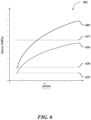
- FIG. 6illustrates a calculation of contact stress during wire feeding
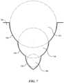
- FIG. 7illustrates a partial cross-sectional view of a multi-groove roller
- FIG. 8shows a computer system that is programmed or otherwise configured to implement methods provided herein.
- FIG. 9 A- 9 Billustrate a surface plot and a graph of the stress experienced by a wire feeding assembly during wire feeding.
- FIG. 10schematically illustrates an example of a wire feeding method.
- three-dimensional objectgenerally refers to an object or a part that is printed by 3D printing.
- the 3D objectmay be at least a portion of a larger 3D object or an entirety of the 3D object.
- supportgenerally refers to a structure that supports a nascent 3D object during printing and supports the 3D object after printing.
- the supportmay be a platform or an object that may not be a platform, such as another 3D object.
- the other objectmay be an object in need of repair or an object that is to be fused to another object (e.g., by a welding-type approach).
- rollergenerally refers to a part that may be in contact with a portion of a feedstock during printing.
- the rollermay have various shapes and sizes.
- the rollermay be circular, triangular, or square, for example.
- the rollermay have at least one groove that is dimensioned to accommodate at least a portion of the feedstock.
- feedstockgenerally refers to a material that is usable alone or in combination with other material to print a 3D object.
- the feedstockmay be (i) a wire, ribbon or sheet, (ii) a plurality of wires, ribbons or sheets, or (iii) a combination of two or more of wires, ribbons and sheets (e.g., combination of wires and ribbons).
- the term “guide”generally refers to a component in a print head that guides a feedstock towards a location on which a 3D object is to be printed, such as into a melt zone adjacent to a support.
- the melt zonemay be on a support or at least a portion of a 3D object.
- the guidemay be a nozzle or a tip, for example.
- the guidemay permit the feedstock to pass towards and in contact with the support.
- the guidemay include an opening, and during use, the feedstock may be directed in contact with the guide through the opening and towards the support.
- the guidemay not include an opening, but may include a surface that comes in contact with the feedstock.
- the feedstockmay slide through, over or under the guide of the print head into the melt zone.
- the guidemay make a sliding contact with the feedstock and conduct electrical current to or from the feedstock.
- the guidemay constrain the feedstock radially.
- a position of the guide relative to the melt zonemay be constrained while the feedstock is moving through the guide towards the melt zone.
- the guidemay come in contact with at least one feedstock.
- the guidemay come in contact with, and in some cases constrain (e.g., radially constrain), at least 1, 2, 3, 4, 5, 6, 7, 8, 9, 10, or more feedstock simultaneously.
- the present disclosureprovides methods and systems for forming a 3D object.
- the 3D objectmay be based on a computer model of the 3D object, such as a computer-aided design (CAD) stored in a non-transitory computer storage medium (e.g., medium).
- CADcomputer-aided design
- the 3D objectmay not be based on any computer model.
- methods and systems of the present disclosuremay be used to, for example, deposit material on another object, couple one object to at least another object (e.g., welding at least two objects together), or cure a defect in an object (e.g., fill a hole or other defect).
- the present disclosureprovides a system for printing a three-dimensional (3D) object.
- the systemmay comprise a support for holding at least a portion of the 3D object during the printing and a feedstock source configured to hold a feedstock.
- the feedstockmay be usable for the printing the 3D object.
- the systemmay comprise a print head comprising a guide.
- the guidemay comprise an opening for directing the feedstock from the feedstock source towards and in contact with the support or a portion of the three-dimensional object adjacent to the support.
- the systemmay include a driver roller.
- the driver rollermay comprise a groove that is configured to (i) accept at least a portion of the feedstock and (ii) direct the at least the portion of the feedstock towards the guide.
- a power sourcemay be in electrical communication with the feedstock and the support.
- the power sourcemay be configured to supply electrical current to the feedstock and the support during the printing.
- a controllermay be in communication with the power source. The controller may be configured to direct the power source to supply the electrical current to the feedstock and the support during the printing under conditions sufficient to melt the feedstock when the feedstock is in contact with the support or the portion of the three-dimensional object.
- the 3D printingmay be performed with at least 1, 2, 3, 4, 5, 6, 7, 8, 9, 10, or more feedstock.
- the 3D printingmay be performed with at most 10, 9, 8, 7, 6, 5, 4, 3, 2, or less feedstock.
- the feedstockmay be (i) a wire, ribbon or sheet, (ii) a plurality of wires, ribbons or sheets, or (iii) a combination of two or more of wires, ribbons and sheets (e.g., combination of wires and ribbons).
- the feedstockmay have other form factors. If multiple feedstocks are used, the multiple feedstocks may be brought together to the opening. Alternatively or in addition to, at least some or each of the multiple feedstocks may be directed to the opening or different openings.
- a cross-sectional diameter of the feed stockmay be at least about 0.01 millimeters (mm), 0.02 mm, 0.03 mm, 0.04 mm, 0.05 mm, 0.06 mm, 0.07 mm, 0.08 mm, 0.09 mm, 0.1 mm, 0.15 mm, 0.2 mm, 0.25 mm, 0.3 mm, 0.35 mm, 0.4 mm, 0.45 mm, 0.5 mm, 1.0 mm, 1.5 mm, 2.0 mm, 2.5 mm, 3.0 mm, 3.5 mm, 4.0 mm, 5 mm, 6 mm, 7 mm, 8 mm, 9 mm, 10 mm or greater.
- the cross-sectional diametermay be less than or equal to 10 mm, 9 mm, 8 mm, 7 mm, 6 mm, 5 mm, 4.0 mm, 3.5 mm, 3.0 mm, 2.5 mm, 2.0 mm, 1.5 mm, 1.0 mm, 0.5 mm, 0.45 mm, 0.4 mm, 0.35 mm, 0.3 mm, 0.25 mm, 0.2 mm, 0.15 mm, 0.1 mm, 0.09 mm, 0.08 mm, 0.07 mm, 0.06 mm, 0.05 mm, 0.04 mm, 0.03 mm, 0.02 mm, 0.01 mm or less.
- the feedstockmay be formed of at least one metal.
- the feedstockcomprises one or more metals selected from the group consisting of steel, stainless steel, iron, copper, gold, silver, cobalt, chromium, nickel, titanium, platinum, palladium, titanium, and aluminum.
- the feedstockcomprises one or more metals selected from the group consisting rare earths, alloys of metals, tool steel alloys, and nickel-based alloys.
- the feedstockmay include at least one non-metal, such as a fiber material (e.g., elemental fiber or nanotube) and/or polymeric material.
- the fiber materialmay include, for example, carbon fiber, carbon nanotubes, and/or graphene.
- the feedstockmay include at least one natural or synthetic ceramic material.
- the natural or synthetic ceramic materialmay be calcium phosphate, calcium carbonate, or silicate.
- Segments of the feedstockmay be printed on the support by melting a tip of the feedstock with an electric current.
- the electric currentmay flow from the guide of the print head through the feedstock and to the support, or vice versa.
- an electric circuitcomprising the guide of the print head, the feedstock, the support, and a power source may be formed.
- the controllermay be operatively coupled to the power source.
- the feedstockmay be a first electrode
- the supportmay be a second electrode. If the feedstock is in physical contact with the support and the power source supplies the electrical current from the guide through the feedstock and to the support, or vice versa, the feedstock and the support are in electrical contact.
- the electrical contactthere may be an electrical resistance between the feedstock and the support (i.e., contact resistance) due to a small surface area of the feedstock and microscopic imperfections on a surface of the tip of the feedstock and/or a surface of the support.
- the heat generated at the local area at the contact between the feedstock and the supportmay be sufficient to melt the tip of the feedstock into a segment and to fuse the segment to the support.
- the heatmay be generated by resistive heating (e.g., Joule heating).
- the segmentis a strand or a particle, which strand or particle may be molten.
- the segmentmay act as a second electrode in the electric circuit to melt and print additional segments of the feedstock.
- the heat generated at the local areamay be sufficient to melt the tip of the feedstock into a segment and to fuse the segment to a segment on the support.
- the heat generated at the local areamay be sufficient to melt the tip of the feedstock into a segment and to fuse the segment to one or more neighboring segments.
- segments of the feedstockmay be deposited without use or generation of electric arcs and/or plasma, but rather by utilizing energy (e.g., electrical energy) within the feedstock.
- the energy within the feedstockmay be to (i) melt at least a portion of the feedstock and (ii) print and/or repair at least a portion of the 3D object.
- the tip of the feedstockmay melt while the feedstock is in contact with the support and the feedstock and the support are moving relative to one another.
- the feedstockis moving and the support is stationary.
- the feedstockis stationary and the support is moving (e.g., along a plane orthogonal to a longitudinal axis of the support perpendicular to the support).
- both the feedstock and the supportare moving (e.g., along a plane orthogonal to a longitudinal axis of the support perpendicular to the support).
- the supportmay be printing platform.
- the supportmay be a previously deposited layer, such as a previously deposited layer of the three-dimensional object or a previously deposited sacrificial layer(s).
- the supportis a part (e.g., part formed by 3D printing or other approaches) and the feedstock is deposited on the part.
- the heat (or temperature) generated at the local area at the contact between the feedstock (e.g., a wire) and the supportmay be at least 100 degrees Celsius (° C.), 200° C., 300° C., 400° C., 500° C., 600° C., 700° C., 800° C., 900° C., 1000° C., 1100° C., 1200° C., 1300° C., 1400° C., 1500° C., 1600° C., 1700° C., 1800° C., 1900° C., 2000° C., 2100° C., 2200° C., 2300° C., 2400° C., 2500° C., 2600° C., 2700° C., 2800° C., 2900° C., 3000° C., 3100° C., 3200° C., 3300° C., 3400° C., 3500° C., 3600° C., 3700° C., 3800° C., 3900
- the heat generated at the local area at the contact between the feedstock and the supportmay be at most 5000° C., 4000° C., 3900° C., 3800° C., 3700° C., 3600° C., 3500° C., 3400° C., 3300° C., 3200° C., 3100° C., 3000° C., 2900° C., 2800° C., 2700° C., 2600° C., 2500° C., 2400° C., 2300° C., 2200° C., 2100° C., 2000° C., 1900° C., 1800° C., 1700° C., 1600° C., 1500° C., 1400° C., 1300° C., 1200° C., 1100° C., 1000° C., 900° C., 800° C., 700° C., 600° C., 500° C., 400° C., 300° C., 200° C., 100° C.
- the heat generated at the local area at the contact between the feedstock and the supportmay not vary depending on a material of the feedstock (e.g., the wire).
- the heat generated at the local area at the contact between the feedstock and the supportmay vary depending on the material of the feedstock.
- the heatmay be at least about 400° C., 410° C., 420° C., 430° C., 440° C., 450° C., 460° C., 470° C., 480° C., 490° C., 500° C., 510° C., 520° C., 530° C., 540° C., 550° C., 560° C., 570° C., 580° C., 590° C., 600° C., 610° C., 620° C., 630° C., 640° C., 650° C., 660° C., 670° C., 680° C., 690° C., 700° C., 710° C., 720° C., 730° C., 740° C., 750° C., 760° C., 770° C., 780° C., 790° C., 800° C., 810°
- the heatmay be at most 1300° C., 1290° C., 1280° C., 1270° C., 1260° C., 1250° C., 1240° C., 1230° C., 1220° C., 1210° C., 1200° C., 1190° C., 1180° C., 1170° C., 1160° C., 1150° C., 1140° C., 1130° C., 1120° C., 1110° C., 1100° C., 1090° C., 1080° C., 1070° C., 1060° C., 1050° C., 1040° C., 1030° C., 1020° C., 1010° C., 1000° C., 990° C., 980° C., 970° C., 960° C., 950° C., 940° C., 930° C., 920° C., 910° C., 900° C., 890°
- the heatmay be at least 800° C., 810° C., 820° C., 830° C., 840° C., 850° C., 860° C., 870° C., 880° C., 890° C., 900° C., 910° C., 920° C., 930° C., 940° C., 950° C., 960° C., 970° C., 980° C., 990° C., 1000° C., 1010° C., 1020° C., 1030° C., 1040° C., 1050° C., 1060° C., 100° C., 1080° C., 1090° C., 1100° C., 1110° C., 1120° C., 1130° C., 1140° C., 1150° C., 1160° C., 1170° C., 1180° C., 1190° C., 1200° C., 1210
- the heatmay be at most 1600° C., 1590° C., 1580° C., 1570° C., 1560° C., 1550° C., 1540° C., 1530° C., 1520° C., 1510° C., 1500° C., 1490° C., 1480° C., 1470° C., 1460° C., 1450° C., 1440° C., 1430° C., 1420° C., 1410° C., 1400° C., 1390° C., 1380° C., 1370° C., 1360° C., 1350° C., 1340° C., 1330° C., 1320° C., 1310° C., 1300° C., 1290° C., 1280° C., 1270° C., 1260° C., 1250° C., 1240° C., 1230° C., 1220° C., 1210° C., 1200° C., 1190° C
- the heatmay be at least 800° C., 810° C., 820° C., 830° C., 840° C., 850° C., 860° C., 870° C., 880° C., 890° C., 900° C., 910° C., 920° C., 930° C., 940° C., 950° C., 960° C., 970° C., 980° C., 990° C., 1000° C., 1010° C., 1020° C., 1030° C., 1040° C., 1050° C., 1060° C., 1070° C., 1080° C., 1090° C., 1100° C., 1110° C., 1120° C., 1130° C., 1140° C., 1150° C., 1160° C., 1170° C., 1180° C., 1190° C., 1200° C., 12
- the heatmay be at most 1600° C., 1590° C., 1580° C., 1570° C., 1560° C., 1550° C., 1540° C., 1530° C., 1520° C., 1510° C., 1500° C., 1490° C., 1480° C., 1470° C., 1460° C., 1450° C., 1440° C., 1430° C., 1420° C., 1410° C., 1400° C., 1390° C., 1380° C., 1370° C., 1360° C., 1350° C., 1340° C., 1330° C., 1320° C., 1310° C., 1300° C., 1290° C., 1280° C., 1270° C., 1260° C., 1250° C., 1240° C., 1230° C., 1220° C., 1210° C., 1200° C., 1190° C
- the heatmay be at least 810° C., 820° C., 830° C., 840° C., 850° C., 860° C., 870° C., 880° C., 890° C., 900° C., 910° C., 920° C., 930° C., 940° C., 950° C., 960° C., 970° C., 980° C., 990° C., 1000° C., 1050° C., 1100° C., 1150° C., 1200° C., 12050° C., 1300° C., 1350° C., 1400° C., 1450° C., 1500° C., 1550° C., 1600° C., 1650° C., 1700° C., 1750° C., 1800° C., 1850° C., 1900° C., 1950° C., 2000° C., 2050° C., 2100° C.,
- the heatmay be at most 2500° C., 2450° C., 2400° C., 2350° C., 2300° C., 2250° C., 2200° C., 2150° C., 2100° C., 2050° C., 2000° C., 1900° C., 1800° C., 1700° C., 1600° C., 1500° C., 1400° C., 1300° C., 1200° C., 1100° C., 1000° C., 990° C., 980° C., 970° C., 960° C., 950° C., 940° C., 930° C., 920° C., 910° C., 900° C., 890° C., 880° C., 870° C., 860° C., 850° C., 840° C., 830° C., 820° C., 810° C., 800° C., or less when the feedstock comprises iron or
- the heatmay be at least 1500° C., 1510° C., 1520° C., 1530° C., 1540° C., 1550° C., 1560° C., 1570° C., 1580° C., 1590° C., 1600° C., 1610° C., 1620° C., 1630° C., 1640° C., 1650° C., 1660° C., 1670° C., 1680° C., 1690° C., 1700° C., 1710° C., 1720° C., 1730° C., 1740° C., 1750° C., 1760° C., 1770° C., 1780° C., 1790° C., 1800° C., 1850° C., 1900° C., 1950° C., 2000° C., 2050° C., 2100° C., 2150° C., 2200° C., 2250° C., 2300° C., or more when the feed
- the heatmay be at most 2300° C., 2250° C., 2200° C., 2150° C., 2100° C., 2050° C., 2000° C., 1950° C., 1900° C., 1850° C., 1800° C., 1790° C., 1780° C., 1770° C., 1760° C., 1750° C., 1740° C., 1730° C., 1720° C., 1710° C., 1700° C., 1690° C., 1680° C., 1670° C., 1660° C., 1650° C., 1640° C., 1630° C., 1620° C., 1610° C., 1600° C., 1590° C., 1580° C., 1570° C., 1560° C., 1550° C., 1540° C., 1530° C., 1520° C., 1510° C., 1500° C., or less when the feedstock comprises platinum
- the heatmay be at least 1200° C., 1210° C., 1220° C., 1230° C., 1240° C., 1250° C., 1260° C., 1270° C., 1280° C., 1290° C., 1300° C., 1310° C., 1320° C., 1330° C., 1340° C., 1350° C., 1360° C., 1370° C., 1380° C., 1390° C., 1400° C., 1410° C., 1420° C., 1430° C., 1440° C., 1450° C., 1460° C., 1470° C., 1480° C., 1490° C., 1500° C., 1510° C., 1520° C., 1530° C., 1540° C., 1550° C., 1560° C., 1570° C., 1580° C., 1590° C., 1600° C., 16
- the heatmay be at most 2100° C., 2050° C., 2000° C., 1950° C., 1900° C., 1850° C., 1800° C., 1750° C., 1700° C., 1650° C., 1600° C., 1590° C., 1580° C., 1570° C., 1560° C., 1550° C., 1540° C., 1530° C., 1520° C., 1510° C., 1500° C., 1490° C., 1480° C., 1470° C., 1460° C., 1450° C., 1440° C., 1430° C., 1420° C., 1410° C., 1400° C., 1390° C., 1380° C., 1370° C., 1360° C., 1350° C., 1340° C., 1330° C., 1320° C., 1310° C., 1300° C., 1290° C., 1280
- the melting point of the alloymay be lower than a melting temperature of one or more base metals of the alloy.
- the melting point of the alloymay be higher than the melting temperature of the one or more base metals of the alloy.
- the melting point of the alloymay be about the same as the melting temperature of the one or more base metals of the alloy.
- the feedstocke.g. a wire
- the electric current from the guide to the feedstock and to the support, or vice versamay range from about 10 Amperes (A) to about 20000 A.
- the electric currentmay be at least about 10 A, 20 A, 30 A, 40 A, 50 A, 60 A, 70 A, 80 A, 90 A, 100 A, 200 A, 300 A, 400 A, 500 A, 600 A, 700 A, 800 A, 900 A, 1000 A, 2000 A, 3000 A, 4000 A, 5000 A, 6000 A, 7000 A, 8000 A, 9000 A, 10000 A, 20000 A or more.
- the electric currentmay be at most about 20000 A, 10000 A, 9000 A, 8000 A, 7000 A, 6000 A, 5000 A, 4000 A, 3000 A, 2000 A, 1000 A, 900 A, 800 A, 700 A, 600 A, 500 A, 400 A, 300 A, 200 A, 100 A, 90 A, 80 A, 70 A, 60 A, 50 A, 40 A, 30 A, 20 A, 10 A or less.
- the duration of the application of the currentmay range from about 0.01 seconds (s) to about 1 s.
- the duration of the application of the currentmay be at least about 0.01 s, 0.02 s, 0.03 s, 0.04 s, 0.05 s, 0.06 s, 0.07 s, 0.08 s, 0.09 s, 0.1 s, 0.2 s, 0.3 s, 0.4 s, 0.5 s, 0.6 s, 0.7 s, 0.8 s, 0.9 s, 1 s or more.
- the duration of the application of the currentmay be at most about 1 s, 0.9 s, 0.8 s, 0.7 s, 0.6 s, 0.5 s, 0.4 s, 0.3 s, 0.2 s, 0.1 s, 0.09 s, 0.08 s, 0.07 s, 0.06 s, 0.05 s, 0.04 s, 0.03 s, 0.02 s, 0.01 s or less.
- the material for the supportmay be selected for good electrical conductivity and compatibility with the feedstock that is being deposited as segments.
- the supportmay be non-consumable and thus need not be replaced during normal operation. Alternatively or in addition to, the support may be replaced after printing one or more 3D objects.
- the supportmay be chosen to allow weak adhesion of the deposited segments to it, so that a first layer of deposited segments may hold the at least the portion of the 3D object firmly in place on the support during further deposition.
- the material for the supportmay have a higher electrical conductivity than the feedstock.
- the material for the supportmay not alloy with the feedstock.
- the material for the supportmay have a higher thermal conductivity than the feedstock, such that heat generated at an area of the feedstock deposition may be quickly conducted away. For example, if the deposited metal is steel, copper or aluminum may be appropriate materials for the support.
- the material for the supportmay have a lower electrical conductivity than the feedstock.
- the application of electric currentmay be controlled to influence the deposition of segments (e.g., size, shape, etc.).
- An open-loop control of the electric currentmay be enabled via choosing a desired intensity level and/or duration of power prior to the deposition of segments.
- the desired intensity level and/or duration of powermay be assigned on the power source or the controller operatively coupled to the power source.
- the desired intensity level of the powermay be calibrated to achieve a specific voltage or current at a constant contact resistance between the feedstock and the support.
- a closed-loop controlmay be used.
- the closed-loop controlmay comprise an electrical measurement meter (e.g., a voltmeter, ammeter, potentiometer, etc.) electrically coupled to the guide of the print head, the feedstock, the support, the power source, and/or the controller operatively coupled to the power source.
- an electrical measurement metere.g., a voltmeter, ammeter, potentiometer, etc.
- voltage and current to the tip of the feedstockmay be measured in situ during deposition of the segments, and the contact resistance between the feedstock and the support may be calculated according to Equation 2 (i.e., Ohm's Law):
- the power sourcemay supply an alternating current (AC) or a direct current (DC) to the feedstock and/or the support.
- the ACmay range from about 1 millivolt (mV) to about 100 volt (V).
- the ACmay be about at least about 1 mV, 2 mV, 3 mV, 4 mV, 5 mV, 6 mV, 7 mV, 8 mV, 9 mV, 10 mV, 20 mV, 30 mV, 40 mV, 50 mV, 60 mV, 70 mV, 80 mV, 90 mV, 100 mV, 200 mV, 300 mV, 400 mV, 500 mV, 600 mV, 700 mV, 800 mV, 900 mV, 1 V, 2 V, 3 V, 4 V, 5 V, 6 V, 7 V, 8 V, 9 V, 10 V, 20 V, 30 V, 40 V, 50 V, 60 V, 70 V, 80 V, 90 V, 100 V, or more.
- the ACmay be at most about 100 V, 90 V, 80 V, 70 V, 60 V, 50 V, 40 V, 30 V, 20 V, 10 V, 9 V, 8 V, 7 V, 6 V, 5 V, 4 V, 3 V, 2 V, 1 V, 900 mV, 800 mV, 700 mV, 600 mV, 500 mV, 400 mV, 300 mV, 200 mV, 100 mV, 90 mV, 80 mV, 70 mV, 60 mV, 50 mV, 40 mV, 30 mV, 20 mV, 10 mV, 9 mV, 8 mV, 7 mV, 6 mV, 5 mV, 4 mV, 3 mV, 2 mV, 1 mV or less.
- the DCmay range from about 1 mV to 100 V.
- the DCmay be about at least about 1 mV, 2 mV, 3 mV, 4 mV, 5 mV, 6 mV, 7 mV, 8 mV, 9 mV, 10 mV, 20 mV, 30 mV, 40 mV, 50 mV, 60 mV, 70 mV, 80 mV, 90 mV, 100 mV, 200 mV, 300 mV, 400 mV, 500 mV, 600 mV, 700 mV, 800 mV, 900 mV, 1 V, 2 V, 3 V, 4 V, 5 V, 6 V, 7 V, 8 V, 9 V, 10 V, 20 V, 30 V, 40 V, 50 V, 60 V, 70 V, 80 V, 90 V, 100 V, or more.
- the DCmay be at most about 100 V, 90 V, 80 V, 70 V, 60 V, 50 V, 40 V, 30 V, 20 V, 10 V, 9 V, 8 V, 7 V, 6 V, 5 V, 4 V, 3 V, 2 V, 1 V, 900 mV, 800 mV, 700 mV, 600 mV, 500 mV, 400 mV, 300 mV, 200 mV, 100 mV, 90 mV, 80 mV, 70 mV, 60 mV, 50 mV, 40 mV, 30 mV, 20 mV, 10 mV, 9 mV, 8 mV, 7 mV, 6 mV, 5 mV, 4 mV, 3 mV, 2 mV, 1 mV or less.
- one pole of the power sourceis attached to the feedstock (e.g., through a guide of the print head) and another pole of the power source is attached to the support.
- the driver rollermay include at least 1, 2, 3, 4, 5, 6, 7, 8, 9, 10, or more grooves. If the driver roller includes multiple grooves, the grooves may be vertically stacked in relation to one another or arranged in a parallel configuration. In some examples, the driver roller includes at least one additional groove adjacent to the groove. The at least one additional groove may be arranged in a parallel fashion to the groove. The at least one additional groove may be configured to (i) accept at least a portion of at least one additional feedstock and (ii) direct the at least the portion of the at least the additional feedstock towards the guide. The driver roller comprising the groove and at least the additional groove may simultaneously direct the feedstock and the at least the additional feedstock along a direction towards the guide.
- the driver rollercomprising the at least one additional groove simultaneously directs the feedstock and the at least one additional feedstock along a direction away from the guide.
- the driver roller with multiple groovesmay have grooves that are arranged equidistantly from each other.
- the groovesmay be arranged on the driver roller with different spacings. For example, if the driver roller has three grooves, a distance between a first groove and a second groove that is arranged directly adjacent to the first groove may be shorter or longer than a distance between the second groove and a third groove that is arranged directly adjacent to the second groove.
- the driver roller comprising the at least the additional groovemay also include a position adjusting mechanism.
- the position adjusting mechanismmay be configured for movement of the driver roller along a rotational axis of the driver roller.
- the position adjusting mechanismmay be configured to move the driver roller into alignment with the feedstock or the at least the additional feedstock. During the alignment, the feedstock or the at least the additional feedstock may line up with the groove or the at least the additional groove of the driver roller.
- the groovemay comprise a radius that is at least about 0 percent (%), 1%, 2%, 3%, 4%, 5%, 6%, 7%, 8%, 9%, 10%, 15%, 20%, 25%, 30%, 35%, 40%, 45%, 50%, 55%, 60%, 65%, 70%, 75%, 80%, 85%, 90%, 95%, or more of a radius of the feedstock.
- the groovemay comprise a radius that is at most about 100%, 95%, 90%, 85%, 80%, 75%, 70%, 65%, 60%, 55%, 50%, 45%, 40%, 35%, 30%, 25%, 20%, 15%, 10%, 9%, 8%, 7%, 6% 5%, 4%, 3%, 2%, 1% or less of a radius of the feedstock.
- the position adjusting mechanism of the driver rollermay be automated.
- the driver rollermay be coupled (e.g., mechanically attached) to the position adjusting mechanism.
- the controllermay be in communication with the position adjusting mechanism.
- the controllermay direct the position adjusting mechanism to move the driver roller during the alignment with the feedstock or the at least the additional feedstock.
- the position adjusting mechanism in communication with the controllermay be a linear actuator.
- the actuator in the position adjusting mechanismmay be an electric linear screw actuator.
- the position adjusting mechanism in communication with the controllermay include one or more linear actuators.
- the position adjusting mechanismcomprises a stage for holding at least the driver roller.
- the stagemay further have one or more linear actuators that are mechanically attached to the stage.
- the systemcomprises a plurality of driver rollers.
- Each driver rollermay be independently coupled (e.g., mechanically attached) to a position adjusting mechanism.
- Each position adjusting mechanismmay be independently in communication with controller.
- the driver rollermay be coupled (e.g., mechanically attached) to an actuator that subjects the driver roller to rotation.
- the actuatormay be a rotary actuator or an electric motor. Such rotation may feed the feedstock along a direction away from the feedstock source towards the opening of the guide.
- the actuatormay rotate the driver roller at a plurality of rotating speeds.
- the actuatormay be configured to accelerate, decelerate, maintain at a given speed of the plurality of rotating speeds, or control a direction of rotation of the driver roller.
- the actuatormay be in communication with the controller.
- the controllermay direct the actuator to rotate the driver roller. Alternatively or in addition to, the actuator may be in communication with a separate actuator controller.
- the driver rolleris not coupled to an actuator, but may be configured to rotate upon application of force to the driver roller.
- forceis provided by an actuator that is mechanically coupled to a feedstock that is in contact with the driver roller.
- the systemmay include at least 1, 2, 3, 4, 5, 6, 7, 8, 9, 10, or more driver rollers.
- the systemmay include less than or equal to 10, 9, 8, 7, 6, 5, 4, 3, 2, or less driver rollers.
- Each driver rollermay be independently coupled to an actuator for subjecting a rotational movement, and each actuator may be independently in communication with the controller.
- the groove on the driver rollermay be a V-groove roller.
- the groovemay be V-shaped when viewed in cross-section.
- An angle between two sides of the V-groovemay be no more than 160 degrees apart.
- the angle between the two sides of the V-groovemay be at most about 150 degrees, 140 degrees, 130 degrees, 120 degrees, 110 degrees, 100 degrees, 90 degrees, 80 degrees, 70 degrees, 60 degrees, 50 degrees, 40 degrees, 30 degrees, 20 degrees, 10 degrees or less apart.
- the groove in the driver rollermay be other than V-shaped, so that the stress(es), possible shavings, or other types of damages imposed on the groove and the feedstock at the contact surface(s) between the groove and the feedstock may be reduced.
- the Hertz contact stress between the groove and the feedstockmay be reduced by using a groove with curved faces.
- the curved facesmay have radii of curvature that deviate from a radius of curvature of the feedstock by at most about 25%, 20%, 15%, 10%, 9%, 8%, 7%, 6% 5%, 4%, 3%, 2%, 1% or less.
- the curved facesmay have radii of curvature that deviate from a radius of a cross-section of the feedstock by at most about 25 percent (%), 20%, 15%, 10%, 9%, 8%, 7%, 6% 5%, 4%, 3%, 2%, 1% or less.
- the curved facesmay have radii of curvature that deviate from a radius of curvature of the feedstock by at least about 1%, 2%, 3%, 4%, 5%, 6%, 7%, 8%, 9%, 10%, 15%, 20%, 25%, or more.
- the curved facesmay have radii of curvature that deviate from a radius of a cross-section of the feedstock by at least about 1%, 2%, 3%, 4%, 5%, 6%, 7%, 8%, 9%, 10%, 15%, 20%, 25%, or more.
- the driver rollermay be a U-groove roller.
- the groovemay be U-shaped when viewed in cross-section.
- a distance between two parallel walls of the U-groovemay be at least 1%, 2%, 3%, 4%, 5%, 6%, 7%, 8%, 9%, 10% or greater than a cross-sectional width of the feedstock.
- a distance between two parallel walls of the U-groovemay be less than or equal to about 15%, 10%, 9%, 8%, 7%, 6% 5%, 4%, 3%, 2%, 1% or less than a cross-sectional width (or size) of the feedstock. In some cases, the distance may be a diameter of the feedstock.
- a radius of curvature of the U-groovemay be substantially the same as a radius of curvature of the feedstock.
- the radius of curvature of the U-groovedeviates from the radius of curvature of the feedstock by at most 30%.
- the radius of curvature of the U-groovedeviates from the radius of curvature of the feedstock by at most 50%.
- the radius of curvature of the U-groovedeviates from the radius of curvature of the feedstock by at most 100%.
- the radius of curvature of the U-groovemay deviate from the radius of curvature of the feedstock by at most about 100%, 90%, 80%, 70%, 60%, 50%, 40%, 30%, 25%, 20%, 15%, 10%, 9%, 8%, 7%, 6% 5%, 4%, 3%, 2%, 1% or less.
- the radius of curvature of the U-groovemay deviate from the radius of curvature of the feedstock by at least about 1%, 2%, 3%, 4%, 5%, 6%, 7%, 8%, 9%, 10%, 15%, 20%, 25%, 30%, 40%, 50%, 60%, 70%, 80%, 90%, 95%, or more.
- the driver rollermay be a concave groove roller.
- the groovemay be concave-shaped when viewed in cross-section.
- An opening of the concave groovemay have a width that deviates at least about 1%, 2%, 3%, 4%, 5%, 6%, 7%, 8%, 9%, 10%, 20%, 30%, 40%, 50%, 100% or more from the cross sectional width of the feedstock.
- An opening of the concave groovemay have a width that deviates less than or equal to about 100%, 50%, 40%, 30%, 20%, 15%, 10%, 9%, 8%, 7%, 6% 5%, 4%, 3%, 2%, 1% or less from the cross sectional width of the feedstock.
- An angle between two sides of the concave groovemay be no more than 170 degrees apart.
- the angle between the two sides of the concave groovemay be at most about 160 degrees, 150 degrees, 140 degrees, 130 degrees, 120 degrees, 110 degrees, 100 degrees, 90 degrees, 80 degrees, 70 degrees, 60 degrees, 50 degrees, 40 degrees, 30 degrees or less apart.
- the angle between the two sides of the concave groovemay be at least about 30 degrees, 40 degrees, 50 degrees, 60 degrees, 70 degrees, 80 degrees, 90 degrees, 100 degrees, 110 degrees, 120 degrees, 130 degrees, 140 degrees, 150 degrees, 160 degrees or more apart.
- the concave shape of the groovemay correspond to at least a vertex section of an ellipsoid or a vesica piscis.
- the concave shapemay have two sides converging at a tip of the vertex section.
- the two sidesmay have radii of curvature that are substantially the same as the radius of curvature of the feedstock.
- the radii of curvature of the two sides of the concave groovemay deviate from the radius of curvature of the feedstock by at most 30%.
- the radii of curvature of the two sides of the concave groovemay deviate from the radius of curvature of the feedstock by at most 50%.
- the radii of curvature of the two sides of the concave groovemay deviate from the radius of curvature of the feedstock by at most 100%.
- the radii of curvature of the two sides of the concave groovemay derivate from the radius of curvature of the feedstock by at most about 100%, 90%, 80%, 70%, 60%, 50%, 40%, 30%, 25%, 20%, 15%, 10%, 9%, 8%, 7%, 6%, 5%, 4%, 3%, 2%, 1% or less.
- the radii of curvature of the two sides of the concave groovemay derivate from the radius of curvature of the feedstock by at least about 1%, 2%, 3%, 4%, 5%, 6%, 7%, 8%, 9%, 10%, 15%, 20%, 25%, 30%, 40%, 50%, 60%, 70%, 80%, 90%, 95% or more.
- the driver rollermay have a complex concave groove to receive at least two feedstocks having different cross-sectional widths.
- the two feedstocksmay have different cross-sectional diameters.
- the complex concave groovemay comprise a plurality of concave grooves of varying dimensions vertically stacked in relation to one another.
- Each side of the complex concave groovemay be a continuation of at least two concave curves. For example, if the side of the complex concave groove has two concave curves, an inner curve that is closer to a rotational axis of the driver roller may have a smaller radius of curvature than an adjacent outer curve that is closer to the outer circumference of the driver roller.
- the surface of the groove in the driver rollermay be partially or entirely smooth, knurled, or serrated to adjust contact surface area and/or frictional force between the groove and the feedstock.
- the feedstock in contact with the driver rollermay be a single feedstock.
- the feedstock in contact with the driver rollermay be a bundle of a plurality of feedstock.
- the bundle of a plurality of feedstockmay be of substantially identical or different materials.
- the substantially identical or different materialsmay have substantially identical or different cross-sectional dimensions.
- the systemmay include an assembly for directing or feeding the feedstock along the direction towards the guide.
- the assemblymay comprise the driver roller and an additional roller.
- the additional rollermay be a preload roller.
- the additional rollermay be positioned above the driver roller with a gap or space between the outer circumferences of the driver roller and the additional roller. The gap or space may be greater than the cross-sectional dimension of the feedstock.
- the additional roller in the assemblymay be configured to (i) contact at least a portion of the feedstock and (ii) direct the at least the portion of the feedstock into the groove of the driver roller of the assembly.
- the additional rollermay be configured with a suitable adjusting mechanism (e.g. a spring or an actuator) that may help vary a force exerted by the additional roller on the at least the portion of the feedstock.
- the outer circumference of the additional rollermay have a shape that corresponds to the shape of the groove of the driver roller. The shape may help directing the at least the portion of the feedstock into the groove.
- the outer circumference of the additional rollermay be partially or entirely smooth, knurled, or serrated to adjust contact surface area and/or frictional force between the groove and the feedstock.
- the systemmay include a feedstock merger.
- the mergermay comprise at least one entry orifice for receiving the feedstock from the assembly and an exit orifice for directing the feedstock towards the guide.
- the mergermay comprise a converging configuration to provide a path for the feedstock from the at least one entry orifice to the exit orifice.
- the converging configuration of the mergermay direct the feedstock from the at least one entry orifice into the exit orifice.
- the mergercomprises a Y-shaped passageway.
- the Y-shaped passagewaymay include two entry channels in contact with two entry orifices, respectively, and one exit channel in contact with the exit orifice.
- the Y-shaped passagewaymay receive a first feedstock and a second feedstock. If the first feedstock is to be used for printing, a first actuator of a first driver roller in contact with the first feedstock may subject the first driver roller to rotation. The rotation of the first driver roller may direct the first feedstock through a first entry channel of the Y-shaped passageway towards the exit channel. A second actuator of a second driver roller in contact with the second feedstock may be idle or turned off during the rotation of the first driver roller.
- the first actuatormay direct the first driver roller to rotate in an opposite direction to withdraw the first feedstock away from the guide and away from the exit channel of the Y-shaped path in the merger.
- the converging configuration of the mergermay be configured to (i) simultaneously receive more than one feedstock from the at least one entry orifice, (ii) arrange the more than one feedstock into a bundle of more than one feedstock, and (iii) direct the bundle of more than one feedstock into the exit orifice.
- the feedstock in the bundle of more than one feedstockmay be arranged in a linear or twisted fashion.
- the mergercomprises a Y-shaped passageway and a tubular channel.
- the Y-shaped pathmay include two entry channels in contact with two entry orifices, respectively, to receive two feedstocks.
- the Y-shaped guide channelmay include one exit channel to simultaneously receive and direct the two feedstocks towards the exit orifice.
- the tubular channelmay be positioned between the exit channel of the Y-shaped passageway and the exit orifice.
- the tubular channelmay comprise an opening to receive one or both of the two feedstocks.
- the tubular channelmay include an actuator to rotate the tubular channel.
- the actuator of the tubular channelmay direct a rotation of the tubular channel as to twist the two feedstocks into a twisted bundle of feedstocks.
- the twisted bundle of feedstocksmay be directed through the exit orifice of the merger towards the guide.
- the tubular channelmay receive the two feedstocks and direct a parallel bundle of the two feedstocks towards the guide while the tubular channel remains stationary.
- the mergermay be in communication with the controller.
- the controllermay be configured to instruct the merger to direct the feedstock from the at least one entry orifice into the exit orifice.
- the controllermay be configured to arrange the more than one feedstock into the bundle.
- the bundlemay be a twisted bundle of at least about 2, 3, 4, 5, 6, 7, 8, 9, 10 or more feedstocks.
- the bundlemay be a twisted bundle of less than or equal to about 10, 9, 8, 7, 6, 5, 4, 3, 2 feedstocks.
- the bundlemay be a parallel bundle of 2, 3, 4, 5, 6, 7, 8, 9, 10 or more feedstocks.
- the bundlemay be a parallel bundle of less than or equal to about 10, 9, 8, 7, 6, 5, 4, 3, 2 feedstocks.
- the assembly comprising the driver roller and the additional rollermay be configured adjacent to the at least one entry orifice of the merger.
- the assemblymay push the feedstock from the feedstock source towards the merger.
- the assemblymay be a pusher assembly or a pusher feeder assembly.
- the systemmay include a buffer idler.
- the buffer idlermay be disposed between the feedstock source and the pusher feeder assembly.
- the buffer idlermay be configured to (i) contact at least a portion of the feedstock and (ii) direct the at least the portion of the feedstock towards the pusher feeder assembly or a puller feeder assembly.
- the buffer idlermay contact and supply a force to the at least the portion of the feedstock to maintain a tension on the feedstock between the feedstock source (e.g., spool, drum, etc.) to the pusher feeder assembly.
- the buffer idlermay be a dancer idler.
- the assemblycomprising the driver roller and the additional roller may be configured adjacent to the exit orifice of the merger.
- the assemblymay pull the feedstock along a direction away from the merger towards the guide.
- the assemblymay be a puller assembly or a puller feeder assembly.
- the mergermay comprise at least one conduit.
- the at least one conduitmay provide a continuous passageway for the feedstock (i) from the pusher assembly to the at least one entry orifice of the merger, (ii) from the exit orifice of the merger to the puller assembly, (iii) or from the puller assembly to the guide.
- One end of the at least one conduitmay be connected to the at least one entry orifice or the exit orifice of the merger to allow a continuous passage for the feedstock.
- the continuous passagewaymay reduce significant wear and wire buckling throughout the system.
- the at least one conduitmay provide a continuous passageway for the feedstock from the puller assembly to the guide.
- the at least one conduitmay provide discontinuous passageway.
- the conduitmay include a blocking unit to open or close the passageway.
- the at least one conduitmay be a flexible tube.
- the at least one conduitmay be an isolated metal tubing.
- the at least one conduitmay be formed of at least one electrical insulator.
- the at least one conduitmay be formed of one or more polymers selected from the group comprising polyacrylics, polyesters, polyvinyls, diallylphthalate and other allylic polymers, polyepoxides, polyurethanes, polyimides, polysiloxanes, fluorocarbons and other fluorinated polymers, polysulfones, polyamides, and polysulfides.
- fluorinated polymersexamples include polyvinylidene fluoride (PVDF), ethylenchlorotrifluoroethylene (ECTFE), ethylenetetrafluoroethylene (ETFE), polytetrafluoroethylene (PTFE), perfluoroalkoxy (PFA), and modified fluoroalkoxy (a copolymer of tetrafluoroethylene and perfluoromethylvinylether, also known as MFA).
- PVDFpolyvinylidene fluoride
- ECTFEethylenchlorotrifluoroethylene
- ETFEethylenetetrafluoroethylene
- PTFEpolytetrafluoroethylene
- PFAperfluoroalkoxy
- modified fluoroalkoxya copolymer of tetrafluoroethylene and perfluoromethylvinylether, also known as MFA.
- the systemmay include at least 1, 2, 3, 4, 5, 6, 7, 8, 9, 10 or more additional buffer idlers.
- the systemmay include less than or equal to about 10, 9, 8, 7, 6, 5, 4, 3, 2, or less additional buffer idlers.
- Each of the at least 1, 2, 3, 4, 5, 6, 7, 8, 9, 10 or more additional buffer idlersmay be disposed between a feedstock source and a pusher feeder assembly, respectively.
- Each of the less than or equal to about 10, 9, 8, 7, 6, 5, 4, 3, 2, or less additional buffer idlersmay be disposed between a feedstock source and a pusher feeder assembly, respectively.
- the systemincludes one additional buffer idler.
- the additional buffer idlermay be disposed between an additional feedstock source and an additional pusher feeder assembly.
- the additional buffer idlermay be configured to (i) contact at least a portion of the feedstock and (ii) direct the at least the portion of the feedstock along a direction towards the guide.
- FIG. 1schematically illustrates an example of a 3D printing system (“system”) 101 .
- the system 101comprises a support 102 for holding at least a portion of the 3D object 103 during printing.
- the system 101also comprises a wire source 104 configured to hold a wire 106 .
- the system 101also comprises an additional wire source 108 configured to hold an additional wire 110 .
- the wires 108 and 110are usable for the printing at least a portion of a larger 3D object or an entirety of the 3D object.
- the system 101comprises a guide 112 , which directs a selected wire 114 from the wires 106 and 110 towards and in contact with the support 102 or a portion of the 3D object adjacent to the support 102 .
- the system 101includes a driver roller 116 .
- the driver roller 116comprises a groove 118 that is configured to (i) accept at least a portion of the wire 106 and (ii) direct the at least the portion of the wire 106 towards the guide 112 .
- the system 101also includes an additional driver roller 120 .
- the driver roller 120comprises a groove 122 that is configured to (i) accept at least a portion of the wire 110 and (ii) direct the at least the portion of the wire 110 towards the guide 112 .
- a power source 124is in electrical communication with the selected wire 114 and the support 102 .
- the power source 124is configured to supply electrical current to the selected wire 114 and the support 102 during the printing.
- a controller 126is in communication with the power source 124 .
- the controller 126is configured to direct the power source 124 to flow the electrical current to the selected wire 114 and the support 102 during the printing under conditions sufficient to melt the selected wire 114 when the selected wire 114 is in contact with the support 102 or the portion of the 3D object. Additionally, the controller 126 is in communication with the driver rollers 116 , 120 , and 152 . The controller is also in communication with the wire sources 104 and 108 .
- the system 101 in FIG. 1includes a pusher feeder assembly 128 for directing or feeding the wire 106 from the wire source 104 along the direction towards the guide 112 .
- the assembly 128comprises the driver roller 116 and a preload roller 130 .
- the preload roller 130is configured to (i) contact at least a portion of the wire 106 and (ii) direct 132 the at least the portion of the wire 106 into the groove 118 of the driver roller 116 .
- the systemalso includes a buffer idler 134 .
- the buffer idler 134is disposed between the wire source 104 and the pusher feeder assembly 128 .
- the buffer feeder 134is configured to (i) contact at least a portion of the wire 106 and (ii) direct the at least the portion of the wire 106 towards the pusher feeder assembly 128 .
- the system 101also includes an additional pusher feeder assembly 136 for directing or feeding the wire 110 from the wire source 108 along the direction towards the guide 112 .
- the assembly 136comprises the driver roller 120 and an additional preload roller 138 .
- the preload roller 138is configured to (i) contact at least a portion of the wire 110 and (ii) direct 140 the at least the portion of the wire 110 into the groove 122 of the driver roller 120 .
- the systemalso includes an additional buffer idler 142 .
- the buffer idler 142is disposed between the wire source 108 and the pusher feeder assembly 136 .
- the buffer feeder 142is configured to (i) contact at least a portion of the wire 110 and (ii) direct the at least the portion of the wire 110 towards the pusher feeder assembly 136 .
- the system 101 in FIG. 1includes a wire merger 144 .
- the wire merger 144is configured to receive the wires 106 and 110 from the pusher feeder assemblies 128 and 136 , respectively, and direct one of the wires 106 and 110 as a selected wire 114 towards the guide 112 . If the wire 106 is to be used to print a portion of a 3D object, the controller may (i) direct the driver roller 120 of the pusher feeder assembly 136 to retract the wire 110 out of the wire merger 144 towards the wire source 108 , and (ii) direct the driver roller 116 of the pusher feeder assembly 128 to direct the wire 106 into the wire merger 144 towards the guide 112 .
- the systemalso includes flexible tubings 146 and 148 .
- the flexible tubings 146 and 148are connected by one end to the wire merger 144 .
- the flexible tubings 146 and 148provide continuous passageways for the wires 106 and 110 , respectively, into the wire merger 144 .
- the flexible tubings 146 and 148reduce significant wear and wire buckling while feeding into the wire merger 144 .
- the system 101 in FIG. 1also includes a puller feeder assembly 150 for directing or feeding the selected wire 114 from the wire merger 144 towards the guide 112 .
- the puller feeder assembly 150comprises an additional driver roller 152 with a groove 154 and an additional preload roller 156 .
- the preload roller 156is configured to (i) contact at least a portion of the selected wire 114 and (ii) direct 158 the at least the portion of the wire 114 into the groove 154 of the driver roller 152 .
- the groove 118 of the driver roller 116 , the groove 122 of the driver roller 120 , and the groove 154 of the driver roller 152may have identical or different dimensions depending on cross-sectional dimensions of the wires 106 , 110 , and 114 .
- the groove 118 of the driver roller 116 , the groove 122 of the driver roller 120 , and the groove 154 of the driver roller 152may have different dimensions if the cross-sections of the wires 106 , 110 , and 114 are different.
- the groove 118may have a dimension that is greater than groove 122 if the wire 106 has a greater cross-section than the wire 110 .
- FIG. 2 A- 2 Cschematically illustrates an example of a driver roller 201 .
- FIG. 2 A- 2 Care side, partial top, and partial cross-sectional views (e.g., a zoomed in view of 201 ), respectively, of a driver roller 201 with a V-groove 205 .
- the angle 210 between two sides of the V-groove 205is illustrated as 35 degrees. In some cases, the angle 210 may be at most about 150 degrees, 140 degrees, 130 degrees, 120 degrees, 110 degrees, 100 degrees, 90 degrees, 80 degrees, 70 degrees, 60 degrees, 50 degrees, 40 degrees, 30 degrees, 20 degrees, 10 degrees or less apart.
- the angle 210may be at least about 5 degrees, 10 degrees, 20 degrees, 30 degrees, 40 degrees, 50 degrees, 60 degrees, 70 degrees, 80 degrees, 90 degrees, 100 degrees, 110 degrees, 120 degrees, 130 degrees, 140 degrees, 150 degrees, or more apart.
- the V-groove geometrycan handle inherent tolerances within a source of wire, but not incremental diameter changes between multiple sources wires.
- a wire diametercan be 0.035 inches (0.89 mm).
- the tolerance on the wirecan be about +/ ⁇ 0.0005 inches (0.013 mm).
- Such tolerance on the wire diametercan be accommodated in a V-groove roller. If it is necessary to change the wire diameter to 0.045 inches (1.14 mm), for instance, the V-groove roller can be adjusted to handle the different wire diameter.
- the adjustment of the V-groove rollercan be accomplished by (i) replacing the V-groove roller with a different V-groove roller that comprises a different V-groove dimension, or (ii) using a multi-groove roller comprising, in parallel, multiple V-grooves with varying widths and angles.
- One or more V-groovescan be formed within a V-groove. Replacing the V-groove roller or adjusting a position of the multi-groove roller in relation to the wire can be a manual user operation or a controller automated process.
- FIG. 3schematically illustrates a partial a cross-sectional view of an assembly 301 while a wire 305 is fed through the assembly.
- the assemblycomprises a driver roller 310 with a V-groove 315 and a preload roller 320 .
- the assemblymay comprise an adjusting mechanism (e.g., a spring or an actuator) to control a force exerted by the preload roller 320 on the wire 305 and towards the V-groove 315 .
- the adjusting mechanismcan push the preload roller 320 to (i) contact at least a portion of the wire 305 and (ii) direct the at least the portion of the wire 305 into the V-groove 315 of the driver roller 310 of the assembly 301 .
- the driver roller 310can be rotationally actuated by an electric motor.
- the preload roller 320can push the wire 305 into the V-groove 315 and create normal forces at three contact surfaces 325 , 330 , and 335 .
- the three contact surfacesinclude a portion of the circumferential surface 325 of the preload roller 320 and a portion of each side 330 and 335 of the V-groove 315 .
- normal forces at the wire-V-groove contact surfacescan be calculated as a function of the V-groove angle ( ⁇ ).
- a traction force (F Traction )is the total force applied axially to the wire 305 by the driver roller 310 .
- Each of the two contact surfacesexperience a normal force (F Normal ) that is generated by a force exerted by the preload roller (F preload ).
- the normal force (F Normal ) multiplied by the static coefficient of friction ( ⁇ Static )provides half of the traction force (F Traction ).
- the normal force (F Normal ) on each of two contact points of the V-grooveis equal to the preload force (F Preload ) divided by 2 times the sine of half the angle of the V-groove.
- F Preloadthe preload force
- F Tractionthe maximum traction force
- a respective preload force (F preload ( ⁇ )) exerted by the preload roller 320can be solved as a function the V-groove angle ( ⁇ ).
- ⁇a wire made of aluminum
- Aluminumhas a static friction coefficient ( ⁇ Static ) of 0.35.
- the minimum traction force (F minTraction ) requiredis 30 newton (N), and thus the minimum normal force (F minNormal ) at each of the contact areas of the V-groove 330 and 335 can be calculated to be about 43 N.
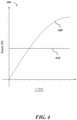
- the graph 401illustrates a plot 405 of the respectively required preload force (F preload ( ⁇ )) as a function of the V-groove angle ( ⁇ ).
- the graph 401also illustrates the minimum normal force (F minNormal) of the V-groove as a constant horizontal plot 410 .
- the graph 401illustrates that, when given such parameters, the required preload force of the preload roller (F preload ( ⁇ )) can exceed the minimum normal force of the V-groove (F minNormal ) when the V-groove angle ( ⁇ ) is greater than 60 degrees.
- the phenomenon of the preload force exerted on the wire exceeding the normal force at the V-groove surfaceis known as a wedging effect. The wedging effect may lead to wear and fretting of the wire, the driver roller, or both.
- a concave groove driver rollermay include two walls. An angle between the two walls of the concave groove may be at most about 160 degrees, 150 degrees, 140 degrees, 130 degrees, 120 degrees, 110 degrees, 100 degrees, 90 degrees, 80 degrees, 70 degrees, 60 degrees, 50 degrees, 40 degrees, 30 degrees or less apart. An angle between the two walls of the concave groove may be at least about 30 degrees, 40 degrees, 50 degrees, 60 degrees, 70 degrees, 80 degrees, 90 degrees, 100 degrees, 110 degrees, 120 degrees, 130 degrees, 140 degrees, 150 degrees, 160 degrees, or more apart.
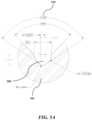
- FIG. 5 Aschematically illustrates a partial cross-sectional view (e.g., a zoomed in view) of a concave groove driver roller 501 with a concave groove 505 .
- the angle 510 between two walls of the concave groove 505is illustrated as about 112 degrees. In some cases, the angle 510 may be less than or greater than 112 degrees.
- the concave groove geometry 505in comparison to the V-groove 315 in the driver roller 310 , may be configured to reduce stress on a wire that is in contact with the concave groove driver roller 501 or portions of the driver roller 501 that are in contact with the wire while the wire is directed from the wire source to the print head during 3D printing.
- FIG. 5 Bschematically illustrates a partial cross-sectional view of an assembly 511 while a wire 515 is fed through the assembly.
- the assemblycomprises a driver roller 520 with a concave groove 525 and a preload roller 530 .
- the assemblycan comprise an adjusting mechanism (e.g., a spring or an actuator) to control a force exerted by the preload roller 530 on the wire 515 and towards the concave groove 525 .
- the adjusting mechanismcan push the preload roller 530 to (i) contact at least a portion of the wire 515 and (ii) direct the at least the portion of the wire 515 into the concave groove 525 of the driver roller 520 of the assembly 511 .
- the driver roller 520can be rotationally actuated by an electric motor.
- the preload roller 530can push the wire 515 into the concave groove 525 and create normal forces at the contact surfaces 535 , 540 , and 545 .
- the contact surfacescan include at least a portion of the circumferential surface 535 of the preload roller 530 and at least a portion of each side 540 and 545 of the concave groove 525 .
- the surface of the preload roller 535 that is in contact with the wire 515may be a concave surface.
- the stress at contact surfaces between two objectscan be calculated as a function of curvatures of faces of the two objects in contact. This calculation may be referred to as Hertz contact stress.
- Hertz contact stressIn a contact between a wire and a groove on a driver roller, the Hertz contact stress can approach a minimum when a radius of curvature of the groove is substantially the same as a radius of curvature of the wire. Therefore, the driver roller 520 can have a concave groove 525 geometry reflecting the radius of curvature of the wire 515 in order to reduce the Hertz contact stress, reduce wear and fretting, and prolong the longevity of the driver roller.
- the present disclosureprovides approaches for calculating the Hertz contact stress of a wire feeding assembly comprising the concave groove driver roller.
- Wires made of aluminum or steelare used in the calculation.
- the friction coefficient ( ⁇ ), Young's modulus (E), Poisson's ratio ( ⁇ ), and tensile yield strength ( ⁇ y ) values of the wiresare provided in TABLE 1.
- Other parameters for calculating the Hertz contact stress of the wire feeding assemblymay include a radius of curvature of the wire (R Wire ), a radius curvature of the driver roller (R Major ), and a radius of curvature of the concave groove (R Minor ).
- c(A R )is a radius of a first axis of the ellipse
- d(A R )is a radius of a second axis of the ellipse.
- ⁇ Normalnormal force
- ⁇ Tractiontraction shear stress
- Equation 9q(A R ) is a normal pressure exerted on the area of contact, described in Equation 9:
- FIG. 6shows a graph 601 of the maximum shear stress exerted on the wire ( ⁇ Max,Wire ) within the concave driver roller 501 as a function of the variable ratio (A R ).
- the top curved line 605 in the graphrepresents a maximum shear stress exerted on a steel wire ( ⁇ maxSteel (A R )), and the bottom curved line 610 represents a maximum shear stress exerted on an aluminum wire ( ⁇ maxAl (A R )).
- the dotted horizontal lines in the graphrepresent the yield strength of the concave driver roller 615 , the steel wire 620 , and the aluminum wire 625 .
- the graphillustrates that, when given such parameters, the maximum shear stress exerted on the wire approaches a minimum when the radius of curvature of the groove of the driver roller is substantially the same as the radius of curvature of the wire.
- stresses in the driver roller and the wire during wire feedingcan be decreased by using a variation of the concave groove roller 501 , where the radius of curvature of the concave groove is substantially the same, or at least about 1%, 2%, 3%, 4%, 5%, 6%, 7%, 8%, 9%, 10%, 20%, 30%, 40%, 50% or greater than the radius of curvature of the wire.
- Stresses in the driver roller and the wire during wire feedingcan be decreased by using a variation of the concave groove roller 501 , where the radius of curvature of the concave groove is substantially the same, or at most about 50%, 40%, 30%, 20%, 10%, 9%, 8%, 7%, 6%, 5%, 4%, 3%, 2%, 1%, or less than the radius of curvature of the wire.
- FIG. 7schematically illustrates a partial cross-sectional view of a complex Hertz roller 701 as a variation of a driver roller that can receive three wires 705 , 710 , and 715 with three discrete diameters.
- the complex Hertz rollercomprises three concave grooves 720 , 725 , and 730 of varying dimensions vertically stacked in relation to one another.
- a radius of curvature of the first groove 720 that is closer to a rotational axis of the complex Hertz rolleris smaller than a radius of curvature of the second groove 725 that is arranged directly above the first groove.
- the radius of curvature of the second groove 725is smaller than the radius of curvature of the third groove 730 that is arranged directly above the third second groove.
- the radius of curvature of the first groove 720is substantially the same, or at least about 1%, 2%, 3%, 4%, 5%, 6%, 7%, 8%, 9%, 10%, 15%, 20%, 25%, 30%, 40%, 50%, or greater than the radius of curvature of the first wire 705 .
- the radius of curvature of the first groove 720is substantially the same, or at most about 50%, 40%, 30%, 25%, 20%, 15%, 10%, 9%, 8%, 7%, 6% 5%, 4%, 3%, 2%, 1% or less than the radius of curvature of the first wire 705 .
- the radius of curvature of the second groove 725is substantially the same, or at least about 1%, 2%, 3%, 4%, 5%, 6%, 7%, 8%, 9%, 10%, 15%, 20%, 25%, 30%, 40%, 50%, or greater than the radius of curvature of the second wire 710 .
- the radius of curvature of the second groove 725is substantially the same, or at most about 50%, 40%, 30%, 25%, 20%, 15%, 10%, 9%, 8%, 7%, 6% 5%, 4%, 3%, 2%, 1% or less than the radius of curvature of the second wire 710 .
- the radius of curvature of the third groove 730is substantially the same, or at least about 1%, 2%, 3%, 4%, 5%, 6%, 7%, 8%, 9%, 10%, 15%, 20%, 25%, 30%, 40%, 50%, or greater than the radius of curvature of the first wire 715 .
- the radius of curvature of the third groove 730is substantially the same, or at most about 50%, 40%, 30%, 25%, 20%, 15%, 10%, 9%, 8%, 7%, 6% 5%, 4%, 3%, 2%, 1% or less than the radius of curvature of the first wire 715 .
- the present disclosureprovides a system for forming a three-dimensional (3D) object.
- the systemmay comprise a roller comprising a groove that is configured to support at least a portion of a wire.
- the systemmay comprise a controller.
- the controllermay direct the roller to bring the wire in contact with a support.
- the controllermay direct generation of heat from within the wire to melt the wire when the wire is in contact with the support, to form at least a portion of the 3D object.
- the systemmay comprise a power supply in electrical communication with the wire and the support.
- the controllermay direct the power supply to supply electrical current from the wire to the support, or vice versa, to generate the heat.
- the systemmay utilize various aspects of the aforementioned systems and methods for printing a 3D object, including a wire source configured to hold a wire.
- the present disclosureprovides a method for printing a three-dimensional (3D) object.
- the methodmay comprise activating a 3D printing system, using a driver roller to direct movement of a feedstock, and directing a power source to supply electrical current to the feedstock and the support during printing.
- the electrical current between the feedstock and the supportmay be sufficient to melt the feedstock when the feedstock is in electrical communication (e.g., contact) with the support or a portion of the 3D object.
- the 3D printing systemmay comprise a support.
- the supportmay hold at least a portion of the 3D object during printing.
- the systemmay comprise a feedstock source.
- the feedstock sourcemay be configured to hold the feedstock.
- the systemmay include a print head.
- the print headmay include a guide comprising an opening for directing the feedstock from the feedstock source towards and in electrical communication (e.g., contact) with the support or the portion of the 3D object adjacent to the support.
- the systemmay include the driver roller.
- the driver rollermay comprise a groove that is configured to (i) accept at least a portion of the feedstock and (ii) direct the at least the portion of the feedstock towards the guide.
- the methodmay further comprise detecting when the feedstock is in contact with the support or the portion of the 3D object, and directing the power source to supply the electrical current to the feedstock and the support when the feedstock is detected to be in contact with the support or the portion of the 3D object.
- the feedstockis detected to be in contact with the support by directing electrical current through the feedstock to the support, or vice versa, such as under a constant applied voltage.
- the flow of currentit may be determined that the feedstock is in electrical communication with the support.
- the methodmay further comprise adjusting a force of contact between the feedstock and the support or another object, such as at least a portion of the 3D object.
- the forcemay be detected by a pressure sensor located on a surface of the support.
- the surface of the supportmay be in contact with the feedstock or at least a portion of the 3D object.
- the force applied by the feedstock to the surface of the supportis measured by a force sensitive resistor.
- a degree of change in resistance of the force sensitive resistormay be detected as force exerted by the feedstock on the support.
- the 3D printing systemmay include one or more actuators (e.g., motor) that permit the force to be adjusted.
- a feedstockmay be provided around a spool and directed to the support using an actuator that turns the spool.
- the actuatormay regulate a rate of rotation or torque applied to the spool to adjust or regulate the force of contact.
- an actuator connected to a driver rollermay regulate a rate of rotation or torque applied to the driver roller to adjust or regulate the force of contact.
- the present disclosureprovides a method for forming a three-dimensional (3D) object.
- a rollercomprising a groove may be provided.
- the groovemay support at least a portion of a wire.
- the rollermay be used to bring the wire in contact with a support.
- Heat from within the wiremay be used to melt the wire when the wire is in contact with the support, thereby forming at least a portion of the 3D object.
- Using heat from within the wire to melt the wiremay comprise directing electrical current from the wire to the support, or vice versa, to generate the heat.
- the methodmay utilize various aspects of the aforementioned systems and methods for printing a 3D object, including directing a power source to supply electrical current.
- FIG. 10schematically illustrates an example of wire feeding method (“method”) 1001 .
- the wire feeding methodis an embodiment for 3D printing method.
- the methodcomprises activating a 3D printing system (process 1010 ).
- the 3D printing systemcomprises one or more components of the system for printing the 3D object, as provided herein.
- the 3D printing systemmay be an embodiment of the aforementioned wire feeding assembly 101 , as illustrated in FIG. 1 .
- the methodcomprises supplying a wire (i.e., a feedstock) through a groove between in a roller (e.g., a driver roller) of the 3D printing system (process 1020 ).
- a wirei.e., a feedstock
- a rollere.g., a driver roller
- the methodcomprises adjusting a speed of the wire through a guide towards a support of the 3D printing system (process 1030 ).
- the methodcomprises measuring a force exerted on the wire by the support (process 1040 ).
- the methodcomprises comparing the measured force (or a plurality of measured forces at one position on the wire in contact with the support) to a threshold, and determining if the force is below the threshold (process 1050 ).
- the thresholdmay be a pre-determined threshold value or range of the force.
- the thresholdmay be a force acceptable by the wire without experiencing a significant damage (e.g., deformation or cut).
- the thresholdmay be a force acceptable by the support without experiencing a significant damage (e.g., deformation or cut).
- the thresholdmay be specific for a type of material the wire is made of. Alternatively or in addition to, the threshold may be a common threshold for different types of materials that different wires are made of.
- the methodcomprises adjusting the speed of the wire through the guide towards the support (e.g., accelerate, decelerate) such that the force exerted on the wire is decreased.
- the methodcomprises using an actuator (e.g., an actuator coupled to the driver roller) to direct the wire through the groove and towards the guide (process 1060 ).
- the guideis part of a print head of the 3D printing system.
- the methodfurther comprises supplying electrical current from the guide through the wire and to the support (or vice versa), under conditions sufficient to melt the wire when the wire is in contact with the support or a portion of a 3D object (process 1070 ).
- the present disclosureprovides a method for printing a three-dimensional (3D) object adjacent to a support (e.g., base), comprising (a) receiving in computer memory a computational representation of the 3D object; (b) using a print head to initiate printing of the 3D object by, (i) directing at least one feedstock through a feeder towards the support and (ii) flowing electrical current through the at least one feedstock and into the support, or vice versa; (c) subjecting the at least one feedstock to heating upon flow of electrical current through the at least one feedstock and into the support, or vice versa, which heating is sufficient to melt at least a portion of the at least one feedstock; (d) depositing at least one layer of the at least the portion of the at least one feedstock or depositing the at least the portion of the at least one feedstock adjacent to the support in accordance with the computational representation of the 3D object, thereby printing the 3D object.
- a supporte.g., base
- the method for printing the 3D objectfurther comprises repeating (d) one or more times to deposit and shape additional portion(s) of the at least one feedstock or at least one other feedstock adjacent to the support. In some embodiments, the method for printing the 3D object further comprises subsequent to (d), changing a relative position of the one or more tips with respect to the at least one layer. A size of the at least the portion of the at least one feedstock may be controllable relative to the feedstock during deposition.
- the present disclosureprovides a computer system 801 that is programmed to implement methods of 3D printing a 3D object in the present disclosure.
- FIG. 8shows the computer system 801 that is programmed or otherwise configured to communicate with and regulate various aspects of a 3D printer of the present disclosure.
- the computer system 801can communicate with a power source or one or more actuators of the 3D printer.
- the computer system 801can direct the power source to supply electrical current to a feedstock for use in printing a 3D object.
- the computer system 801may also be programmed to communicate with a plurality of feedstock feeding assemblies. Each feedstock feeding assembly may comprise a driver roller and a preload roller, and the computer system 801 can be programmed to communicate with the driver roller and the preload roller independently or simultaneously.
- the computer system 801can accelerate, decelerate, maintain at a given speed of a plurality of rotating speeds, or control a direction of rotation of the driver roller.
- the computer 801can control the pressure of the preload roller as the preload roller pushes the feedstock into the driver roller.
- the computer system 801may also be programmed to communicate with a feedstock merger to direct the wire merger to receive the feedstock from the plurality of feedstocks sources and direct at least one feedstock to the guide of the print head.
- the computer system 801can be an electronic device of a user or a computer system that is remotely located with respect to the electronic device.
- the electronic devicecan be a mobile electronic device.
- the computer system 801includes a central processing unit (CPU, also “processor” and “computer processor” herein) 805 , which can be a single core or multi core processor, or a plurality of processors for parallel processing.
- the computer system 801also includes memory or memory location 810 (e.g., random-access memory, read-only memory, flash memory), electronic storage unit 815 (e.g., hard disk), communication interface 820 (e.g., network adapter) for communicating with one or more other systems, and peripheral devices 825 , such as cache, other memory, data storage and/or electronic display adapters.
- the memory 810 , storage unit 815 , interface 820 and peripheral devices 825are in communication with the CPU 805 through a communication bus (solid lines), such as a motherboard.
- the storage unit 815can be a data storage unit (or data repository) for storing data.
- the computer system 801can be operatively coupled to a computer network (“network”) 830 with the aid of the communication interface 820 .
- the network 830can be the Internet, an internet and/or extranet, or an intranet and/or extranet that is in communication with the Internet.
- the network 830in some cases is a telecommunication and/or data network.
- the network 830can include one or more computer servers, which can enable distributed computing, such as cloud computing.
- the network 830in some cases with the aid of the computer system 801 , can implement a peer-to-peer network, which may enable devices coupled to the computer system 801 to behave as a client or a server.
- the CPU 805can execute a sequence of machine-readable instructions, which can be embodied in a program or software.
- the instructionsmay be stored in a memory location, such as the memory 810 .
- the instructionscan be directed to the CPU 805 , which can subsequently program or otherwise configure the CPU 805 to implement methods of the present disclosure. Examples of operations performed by the CPU 805 can include fetch, decode, execute, and writeback.
- the CPU 805can be part of a circuit, such as an integrated circuit.
- a circuitsuch as an integrated circuit.
- One or more other components of the system 801can be included in the circuit.
- the circuitis an application specific integrated circuit (ASIC).
- the storage unit 815can store files, such as drivers, libraries and saved programs.
- the storage unit 815can store user data, e.g., user preferences and user programs.
- the computer system 801in some cases can include one or more additional data storage units that are external to the computer system 801 , such as located on a remote server that is in communication with the computer system 801 through an intranet or the Internet.
- the computer system 801can communicate with one or more remote computer systems through the network 830 .
- the computer system 801can communicate with a remote computer system of a user.
- remote computer systemsinclude personal computers (e.g., portable PC), slate or tablet PC's (e.g., Apple® iPad, Samsung® Galaxy Tab), telephones, Smart phones (e.g., Apple® iPhone, Android-enabled device, Blackberry®), or personal digital assistants.
- the usercan access the computer system 801 via the network 830 .
- Methods as described hereincan be implemented by way of machine (e.g., computer processor) executable code stored on an electronic storage location of the computer system 801 , such as, for example, on the memory 810 or electronic storage unit 815 .
- the machine executable or machine readable codecan be provided in the form of software.
- the codecan be executed by the processor 805 .
- the codecan be retrieved from the storage unit 815 and stored on the memory 810 for ready access by the processor 805 .
- the electronic storage unit 815can be precluded, and machine-executable instructions are stored on memory 810 .
- the codecan be pre-compiled and configured for use with a machine having a processer adapted to execute the code, or can be compiled during runtime.
- the codecan be supplied in a programming language that can be selected to enable the code to execute in a pre-compiled or as-compiled fashion.
- aspects of the systems and methods provided hereincan be embodied in programming.
- Various aspects of the technologymay be thought of as “products” or “articles of manufacture” typically in the form of machine (or processor) executable code and/or associated data that is carried on or embodied in a type of machine readable medium.
- Machine-executable codecan be stored on an electronic storage unit, such as memory (e.g., read-only memory, random-access memory, flash memory) or a hard disk.
- “Storage” type mediacan include any or all of the tangible memory of the computers, processors or the like, or associated modules thereof, such as various semiconductor memories, tape drives, disk drives and the like, which may provide non-transitory storage at any time for the software programming. All or portions of the software may at times be communicated through the Internet or various other telecommunication networks. Such communications, for example, may enable loading of the software from one computer or processor into another, for example, from a management server or host computer into the computer platform of an application server.
- another type of media that may bear the software elementsincludes optical, electrical and electromagnetic waves, such as used across physical interfaces between local devices, through wired and optical landline networks and over various air-links.
- a machine readable mediumsuch as computer-executable code
- a tangible storage mediumsuch as computer-executable code
- Non-volatile storage mediainclude, for example, optical or magnetic disks, such as any of the storage devices in any computer(s) or the like, such as may be used to implement the databases, etc. shown in the drawings.
- Volatile storage mediainclude dynamic memory, such as main memory of such a computer platform.
- Tangible transmission mediainclude coaxial cables; copper wire and fiber optics, including the wires that comprise a bus within a computer system.
- Carrier-wave transmission mediamay take the form of electric or electromagnetic signals, or acoustic or light waves such as those generated during radio frequency (RF) and infrared (IR) data communications.
- RFradio frequency
- IRinfrared
- Common forms of computer-readable mediatherefore include for example: a floppy disk, a flexible disk, hard disk, magnetic tape, any other magnetic medium, a CD-ROM, DVD or DVD-ROM, any other optical medium, punch cards paper tape, any other physical storage medium with patterns of holes, a RAM, a ROM, a PROM and EPROM, a FLASH-EPROM, any other memory chip or cartridge, a carrier wave transporting data or instructions, cables or links transporting such a carrier wave, or any other medium from which a computer may read programming code and/or data.
- Many of these forms of computer readable mediamay be involved in carrying one or more sequences of one or more instructions to a processor for execution.
- the computer system 801can include or be in communication with an electronic display 835 that comprises a user interface (UI) 840 for providing, for example, (i) activate or deactivate a 3D printer for printing 3D object, (ii) determine a selected feedstock from the plurality of feedstock sources for printing a portion of the 3D object based on a computer modeling of the 3D object, or (iii) determine operating positions or speeds of a plurality of feedstock feeding assemblies to adjust a printing speed.
- UI'sinclude, without limitation, a graphical user interface (GUI) and web-based user interface.
- An algorithmcan be implemented by way of software upon execution by the central processing unit 805 .
- the algorithmcan, for example, (i) assign a specific feedstock or a combination of at least two or more feedstocks selected from the plurality of feedstock sources to at least one of point (e.g. voxel) of the 3D object and (ii) communicate with the feedstock merger to feed the specific feedstock or the combination of at least two or more feedstocks to the guide of the print head during printing the at least one voxel of the 3D object.
- This exampleprovides finite element analysis (FEA) simulations of wire deformation in a wire feeding assembly that comprises a driver roller and a preload roller.
- the FEA simulationsare performed using computer software (e.g., COMSOL Multiphysics, Flow 3D, solidworks, MATLAB).
- the wire, the groove of the driver roller, and the preload rollerare subjected under a strain, then solved for their von Mises stresses.
- the driver roller and the preload rollercomprise 440C steel, and the wire is an aluminum wire having a diameter of 0.25 millimeter (mm).
- a displacement of 2.5 micrometer ( ⁇ m)is represented as a unit of 1 during simulation.
- the 2.5 micrometer ( ⁇ m) displacementis substantially equal to 1% strain in the aluminum wire.
- This FEA simulation modeltakes into account plastic deformation by using the Ramberg-Osgood stress-strain relationship, and solves for the effective plastic strain using isotropic hardening with tangent data from the Ramberg-Osgood model.
- FIG. 9 Aschematically illustrates a partial, sagittal cross-sectional view of a wire 905 that is in contact with a concave groove driver roller 910 and a preload roller 915 .
- the wire 905is an aluminum wire.
- a radius of curvature of a surface of the preload rolleris greater than a radius of curvature of the wire, while a radius of curvature of the concave groove of the driver roller is substantially the same as the radius of curvature of the wire.
- the wire 905is presented as a surface plot showing the magnitude of stress on the wire when a force of about 3 Newton (N) is applied by the preload roller 915 .
- the force of 3 Nmay be the force required to direct the wire to a print head during printing at least a portion of a 3D object.
- the magnitudes of the stress( 921 , 922 , 923 , 924 , 925 , 926 , 927 , and 928 ) are presented in a decreasing manner from 921 to 928 .
- the surface plotpredicts that the exerted stress on the wire may be greater at a contact surface between the preload roller and the wire than at a contact surface between the driver roller and the wire.
- the differences in the exerted stress between the two contact surfacesmay be due to the difference between the radii of curvature of the surface of the preload roller and the groove of the driver roller.
- the surface plotpredicts that the overall exerted stress on the wire by the assembly comprising the concave groove driver roller and the preload roller is localized and does not severely deform the wire.
- FIG. 9 Bshows a plot 950 of the von Mises stress experienced by the aluminum wire 905 , the driver roller 910 , and the preload roller 915 under strain.
- a displacement of 2.5 ⁇ mis represented as a unit of 1.
- a 2.5 ⁇ m displacementequals to a strain of 1%.
- the stresses experienced by the preload roller 915 , the driver roller 910 , and the aluminum wire 905are predicted to be about 500 megapascal (MPa), 400 MPa, and 340 MPa, respectively.
- the stress experienced by the aluminum wire 905is comparable to the yield strength ( ⁇ y ) of the material (310 mPa).
- the preload roller 915 and the driver roller 910 in the assemblydo not experience enough stress to deform plastically, and may be used without being replaced frequently.
Landscapes
- Engineering & Computer Science (AREA)
- Chemical & Material Sciences (AREA)
- Materials Engineering (AREA)
- Manufacturing & Machinery (AREA)
- Mechanical Engineering (AREA)
- Physics & Mathematics (AREA)
- Optics & Photonics (AREA)
Abstract
Description
Q=I2·R·t (Equation 1)
- where Q is the heat generated at the local area at the contact,
- I is the electric current,
- R is the contact resistance between the feedstock and the support, and
- t is a duration of an application of the current.
- where V is the voltage,
- I is the electric current, and
- R is the contact resistance between the feedstock and the support.
The closed-loop control may beneficially eliminate failed parts due to incomplete fusion of segments and minimize heat input into the structure during deposition.
RMinor(AR):=ARπ·RWire (Equation 4)
| TABLE 1 |
| Materials properties metal wires. |
| μ | E (GPa) | η | σy(MPa) | |
| steel | 0.31 | 200 | 0.30 | 450 |
| SS | 0.31 | 193 | 0.31 | 290 |
| Al | 0.35 | 69 | 0.33 | 276 |
| Ti | 0.36 | 114 | 0.34 | 880 |
| Cu | 0.32 | 117 | 0.36 | 333 |
a(AR):=π·c(AR)·d(AR) (Equation 5)
Given a 440C stainless steel driver roller with Poisson's ratio (η) of 0.31, a tensile yield strength (σy) of 1280 megapascal (MPa), and Young's modulus (E) of 200 gigapascal (GPa), a minimum traction force (FminTraction) of 30 N, a minimum normal force (FminNormal) of about 43 N, a radius of curvature of the wire of 12.5 mm, a radius curvature of the driver roller (RMajor) of 25 mm, and a V-groove angle of 45 degrees, the Hertz stress calculations can be solved for the maximum shear stress exerted on the wire (τMax,Wire).
Claims (20)
Priority Applications (4)
| Application Number | Priority Date | Filing Date | Title |
|---|---|---|---|
| US17/098,564US12330211B2 (en) | 2018-06-20 | 2020-11-16 | Multi-diameter wire feeder |
| US18/665,496US12377459B2 (en) | 2018-06-20 | 2024-05-15 | Multi-diameter wire feeder |
| US19/190,455US20250256327A1 (en) | 2018-06-20 | 2025-04-25 | Multi-Diameter Wire Feeder |
| US19/209,720US20250276362A1 (en) | 2018-06-20 | 2025-05-15 | Multi-Diameter Wire Feeder |
Applications Claiming Priority (3)
| Application Number | Priority Date | Filing Date | Title |
|---|---|---|---|
| US201862687651P | 2018-06-20 | 2018-06-20 | |
| PCT/US2019/038052WO2019246308A1 (en) | 2018-06-20 | 2019-06-19 | Multi-diameter wire feeder |
| US17/098,564US12330211B2 (en) | 2018-06-20 | 2020-11-16 | Multi-diameter wire feeder |
Related Parent Applications (1)
| Application Number | Title | Priority Date | Filing Date |
|---|---|---|---|
| PCT/US2019/038052ContinuationWO2019246308A1 (en) | 2018-06-20 | 2019-06-19 | Multi-diameter wire feeder |
Related Child Applications (1)
| Application Number | Title | Priority Date | Filing Date |
|---|---|---|---|
| US18/665,496ContinuationUS12377459B2 (en) | 2018-06-20 | 2024-05-15 | Multi-diameter wire feeder |
Publications (2)
| Publication Number | Publication Date |
|---|---|
| US20210138538A1 US20210138538A1 (en) | 2021-05-13 |
| US12330211B2true US12330211B2 (en) | 2025-06-17 |
Family
ID=68984242
Family Applications (4)
| Application Number | Title | Priority Date | Filing Date |
|---|---|---|---|
| US17/098,564Active2042-02-15US12330211B2 (en) | 2018-06-20 | 2020-11-16 | Multi-diameter wire feeder |
| US18/665,496ActiveUS12377459B2 (en) | 2018-06-20 | 2024-05-15 | Multi-diameter wire feeder |
| US19/190,455PendingUS20250256327A1 (en) | 2018-06-20 | 2025-04-25 | Multi-Diameter Wire Feeder |
| US19/209,720PendingUS20250276362A1 (en) | 2018-06-20 | 2025-05-15 | Multi-Diameter Wire Feeder |
Family Applications After (3)
| Application Number | Title | Priority Date | Filing Date |
|---|---|---|---|
| US18/665,496ActiveUS12377459B2 (en) | 2018-06-20 | 2024-05-15 | Multi-diameter wire feeder |
| US19/190,455PendingUS20250256327A1 (en) | 2018-06-20 | 2025-04-25 | Multi-Diameter Wire Feeder |
| US19/209,720PendingUS20250276362A1 (en) | 2018-06-20 | 2025-05-15 | Multi-Diameter Wire Feeder |
Country Status (5)
| Country | Link |
|---|---|
| US (4) | US12330211B2 (en) |
| EP (1) | EP3810402A4 (en) |
| JP (1) | JP2021527582A (en) |
| CA (1) | CA3101061A1 (en) |
| WO (1) | WO2019246308A1 (en) |
Families Citing this family (7)
| Publication number | Priority date | Publication date | Assignee | Title |
|---|---|---|---|---|
| MX2017007479A (en) | 2014-12-12 | 2018-05-07 | Digital Alloys Incorporated | Additive manufacturing of metallic structures. |
| EP3810402A4 (en) | 2018-06-20 | 2022-06-29 | Digital Alloys Incorporated | Multi-diameter wire feeder |
| US11853033B1 (en) | 2019-07-26 | 2023-12-26 | Relativity Space, Inc. | Systems and methods for using wire printing process data to predict material properties and part quality |
| CN116490340A (en)* | 2020-08-27 | 2023-07-25 | 特温特大学 | In Situ Monitoring for Additive Manufacturing |
| CN113799391B (en)* | 2021-09-15 | 2023-04-18 | 泉州信息工程学院 | 3D printer multicolor wire feeding device and working method thereof |
| FR3126912B1 (en)* | 2021-09-16 | 2024-01-12 | Airbus Operations Sas | Deposit head of a three-dimensional printing machine configured to deposit several wires simultaneously and three-dimensional printing machine comprising said deposit head |
| CN113968022B (en)* | 2021-11-22 | 2023-07-25 | 宁波大学科学技术学院 | A mixing and feeding device for a three-dimensional printer |
Citations (231)
| Publication number | Priority date | Publication date | Assignee | Title |
|---|---|---|---|---|
| US2799769A (en) | 1955-09-26 | 1957-07-16 | Liquid Carbonic Corp | Shielding gas supply assembly for arc welding torch |
| US3331545A (en) | 1964-11-10 | 1967-07-18 | Union Carbide Corp | Wire feed assembly |
| US3344305A (en) | 1965-12-06 | 1967-09-26 | Ogden Eng Corp | Tandem drive welding wire feed arrangement for semi-automatic welding equipment |
| US3447730A (en) | 1966-04-15 | 1969-06-03 | Air Reduction | Wire feed apparatus |
| US3555235A (en) | 1967-11-13 | 1971-01-12 | Ibm | Metallic surface fusion apparatus |
| US3562577A (en) | 1968-07-11 | 1971-02-09 | Mk Prod Inc | Electrode wire feeding means for welding apparatus |
| US3694620A (en) | 1970-12-10 | 1972-09-26 | William R Gleason | Dual welding wire feed for arc welder |
| GB1387113A (en) | 1971-03-30 | 1975-03-12 | Cranfield Inst Of Tech | Speed control system for grinding machines |
| GB1394291A (en) | 1972-02-07 | 1975-05-14 | Cranfield Inst Of Tech | Gramophone turntable apparatus |
| DE2515625A1 (en) | 1974-04-10 | 1975-10-30 | Cranfield Inst Of Technology C | CONTROL DEVICE FOR MACHINE TOOLS |
| US3934482A (en) | 1975-01-27 | 1976-01-27 | The United States Of America As Represented By The Secretary Of The Navy | Cable traction sheave |
| CH583605A5 (en) | 1972-03-03 | 1977-01-14 | Cranfield Inst Of Tech | |
| DE2537758A1 (en) | 1975-08-25 | 1977-03-10 | Cranfield Inst Of Technology C | High quality record turntable - uses hydrodynamic bearings and controlled speed drive with velocity feedback tachometer |
| US4043494A (en) | 1976-02-23 | 1977-08-23 | Amp Incorporated | Apparatus for feeding a plurality of wires |
| US4047656A (en) | 1976-03-03 | 1977-09-13 | Mac Machine & Metal Works Inc. | Orbital motion welding head |
| US4228338A (en) | 1978-06-08 | 1980-10-14 | Massachusetts Institute Of Technology | Process for implanting radioactive metal on a substrate |
| JPS56168967A (en) | 1980-05-30 | 1981-12-25 | Mitsubishi Electric Corp | Wire feeder for welding |
| US4333594A (en) | 1979-04-14 | 1982-06-08 | Carl Cloos Verwaltungsgesellschaft Ohg | Planet guide roller feed arrangement for melting welding wires |
| DE8126084U1 (en) | 1981-09-08 | 1983-03-17 | Dinse, Wilhelm, 2000 Hamburg | Arc shielding gas welding gun |
| JPS5853382A (en) | 1981-09-25 | 1983-03-29 | Akira Sato | Pattern working method of metallic surface |
| JPS59223174A (en) | 1983-06-02 | 1984-12-14 | Mitsubishi Electric Corp | Filler metal feeding device |
| JPS6021385A (en) | 1983-07-15 | 1985-02-02 | Inoue Japax Res Inc | Die steel |
| GB2185821A (en) | 1986-01-24 | 1987-07-29 | Cranfield Inst Of Technology T | Tetracyano-quinodimethane comprising electrochemical electrode |
| GB2188728A (en) | 1986-04-07 | 1987-10-07 | Cranfield Inst Of Technology T | Specific binding assays |
| US4866237A (en) | 1982-09-21 | 1989-09-12 | Inoue-Japax Research Inc. | Method of discharge coating and an apparatus therefor |
| DE3922560A1 (en) | 1989-07-08 | 1991-01-10 | Ief Werner Gmbh | Controlled feed of wire filler material in soldering and welding - in which feed rate is adjusted to maintain constant feed force |
| US5137223A (en) | 1990-04-09 | 1992-08-11 | The United States Of America As Represented By The United States Department Of Energy | Precision wire feeder for small diameter wire |
| WO1996011117A1 (en) | 1994-10-07 | 1996-04-18 | Helisys, Inc. | Forming integral objects from laminations |
| IL109812A (en) | 1993-05-28 | 1996-11-14 | Cranfield Biotech Ltd | Electrochemical metal analysis apparatus |
| US5736188A (en) | 1994-08-08 | 1998-04-07 | Alcock; Susan | Printed fluid transport devices |
| GB2337332A (en) | 1998-05-13 | 1999-11-17 | Univ Cranfield | Affinity electrode for electrochemical analysis |
| US6004124A (en) | 1998-01-26 | 1999-12-21 | Stratasys, Inc. | Thin-wall tube liquifier |
| CA2388130A1 (en) | 1999-10-23 | 2001-05-03 | Cranfield University | Molecularly imprinted polymers produced by template polymerisation |
| GB2357281A (en) | 1999-12-16 | 2001-06-20 | Univ Cranfield | Fabrication of ceramic films |
| CA2398175A1 (en) | 2000-01-25 | 2001-08-02 | Cranfield University | Molecularly imprinted polymer |
| US6335511B1 (en) | 1999-04-12 | 2002-01-01 | Tri Tool Inc. | Control method and apparatus for an arc welding system |
| US6391251B1 (en) | 1999-07-07 | 2002-05-21 | Optomec Design Company | Forming structures from CAD solid models |
| US6443352B1 (en) | 1999-09-27 | 2002-09-03 | Solidica, Inc. | Electrical resistance based object consolidation |
| US6557742B1 (en) | 2001-04-18 | 2003-05-06 | Lincoln Global, Inc. | Drive roller for wire feeding mechanism |
| US6568578B1 (en) | 2001-03-02 | 2003-05-27 | Mk Products | Welding wire feed mechanism |
| CA2487516A1 (en) | 2002-06-12 | 2003-12-24 | Cranfield University | Temporary tattoo for testing the sensitivity of skin to chemicals |
| US6776602B2 (en) | 1999-04-20 | 2004-08-17 | Stratasys, Inc. | Filament cassette and loading system |
| WO2004070345A2 (en) | 2003-02-07 | 2004-08-19 | Cranfield University | Age determination on death |
| US20040179217A1 (en) | 2003-03-14 | 2004-09-16 | Chapman Alexander L. | Methods and systems to calibrate media indexing errors in a printing device |
| US20050017411A1 (en) | 2003-07-11 | 2005-01-27 | Yang Dong Yol | Three-dimensional shaping apparatus and method using non-contact type heating tool |
| GB2407154A (en) | 2003-10-13 | 2005-04-20 | Univ Cranfield | Acoustic emission sensor based on a fused tapered optical coupler with sharp taper angle |
| US6910360B2 (en)* | 2001-10-23 | 2005-06-28 | L&P Property Management Company | Multiple wire feed for spring coiling machine and method |
| US20050224486A1 (en) | 2004-04-08 | 2005-10-13 | Illinois Tool Works Inc. | Wire feeder pinch force mechanism |
| WO2005114329A2 (en) | 2004-05-21 | 2005-12-01 | Cranfield University | Fabrication of polymeric structures |
| US20060070985A1 (en) | 2004-10-05 | 2006-04-06 | Fanuc Ltd | Arc welding device and arc welding robot system |
| DE60021726T2 (en) | 1999-05-07 | 2006-06-01 | Cranfield University, Cranfield | ULTRASOUND ENGINES |
| US7062849B2 (en) | 2001-10-03 | 2006-06-20 | Yazaki Corporation | Method for producing circuitry using molten metal droplets |
| US7073561B1 (en) | 2004-11-15 | 2006-07-11 | Henn David S | Solid freeform fabrication system and method |
| DE60304043T2 (en) | 2002-07-11 | 2006-10-05 | Cranfield University, Milton Keynes | METHOD FOR PRODUCING A MICROFLUIDIC DEVICE |
| WO2006123130A1 (en) | 2005-05-17 | 2006-11-23 | Cranfield University | Electroluminescent devices |
| WO2006131726A1 (en) | 2005-06-08 | 2006-12-14 | Cranfield University | Polymeric binding materials |
| WO2006133034A1 (en) | 2005-06-06 | 2006-12-14 | Mts Systems Corporation | Direct metal deposition using laser radiation and electric arc |
| WO2007000583A1 (en) | 2005-06-25 | 2007-01-04 | Cranfield University | Method and apparatus for elemental analysis |
| US7168935B1 (en) | 2002-08-02 | 2007-01-30 | The United States Of America As Represented By The Administrator Of The National Aeronautics And Space Administration | Solid freeform fabrication apparatus and methods |
| US7235149B2 (en) | 2000-07-28 | 2007-06-26 | Hypercar, Inc. | Process and equipment for manufacture of advanced composite structures |
| US20070158323A1 (en) | 2006-01-06 | 2007-07-12 | Lincoln Global, Inc. | Grounding assembly for welding wire feeder |
| WO2007107720A2 (en) | 2006-03-17 | 2007-09-27 | Cranfield University | Binding drugs of abuse |
| WO2008001071A2 (en) | 2006-06-27 | 2008-01-03 | Cranfield University | Seat |
| GB2440209A (en) | 2006-07-18 | 2008-01-23 | Univ Cranfield | Nucleic acid arrays replication |
| US7335854B2 (en) | 2005-03-11 | 2008-02-26 | Illinois Tool Works Inc. | Method and system of determining wire feed speed |
| US20080073330A1 (en) | 2006-09-21 | 2008-03-27 | Iiiinois Tool Works Inc. | Dual power integrated MIG welder and generator system |
| US7384255B2 (en) | 2005-07-01 | 2008-06-10 | Stratasys, Inc. | Rapid prototyping system with controlled material feedstock |
| WO2008068503A2 (en) | 2006-12-07 | 2008-06-12 | Cranfield University | Axial flux electrical machines |
| US20080156783A1 (en) | 2006-12-29 | 2008-07-03 | Vanden Heuvel Michael L | Portable multi-wire feeder |
| GB2446880A (en) | 2007-02-24 | 2008-08-27 | Univ Cranfield | Imaging fluid flow properties using Doppler optical coherence tomography |
| US20090025208A1 (en) | 2007-07-27 | 2009-01-29 | Tyco Electronics Corporation | Wire positiong device for a wire termination machine |
| WO2009044177A1 (en) | 2007-10-04 | 2009-04-09 | Cranfield University | Optical monitoring method |
| WO2010041041A1 (en) | 2008-10-10 | 2010-04-15 | Cranfield Universtiy | Method, system and apparatus for reducing oxyanion content |
| US7700893B2 (en) | 2004-12-22 | 2010-04-20 | Illinois Tool Works Inc. | System and method for calibrating wire feeder motor control |
| CN101733521A (en) | 2009-12-11 | 2010-06-16 | 杭州凯尔达电焊机有限公司 | Double eccentric wheel type push-pull pulsed wire feeding method and device |
| US7754597B2 (en) | 2005-07-27 | 2010-07-13 | Seiko Epson Corporation | Bonding pad fabrication method, method for fabricating a bonding pad and an electronic device, and electronic device |
| US7896209B2 (en) | 2008-04-30 | 2011-03-01 | Stratasys, Inc. | Filament drive mechanism for use in extrusion-based digital manufacturing systems |
| US7897074B2 (en) | 2008-04-30 | 2011-03-01 | Stratasys, Inc. | Liquefier assembly for use in extrusion-based digital manufacturing systems |
| US20110111350A1 (en) | 2008-03-26 | 2011-05-12 | Dhana Lakshmi | Conjugated Polymers |
| WO2011067563A1 (en) | 2009-12-01 | 2011-06-09 | Cranfield University | Preparation of molecularly imprinted polymers |
| US20110150517A1 (en) | 2008-09-15 | 2011-06-23 | Martin Chauvin | Method And System For Maintaining Substantially Uniform Pressure Between Rollers Of A Printer |
| US20110240607A1 (en) | 2010-03-31 | 2011-10-06 | Sciaky, Inc. | Raster methodology, apparatus and system for electron beam layer manufacturing using closed loop control |
| US20110278175A1 (en) | 2010-05-12 | 2011-11-17 | Michael James Whitcombe | Aniline Derivatives, Polymers, and Uses Thereof |
| US20110309063A1 (en) | 2010-06-17 | 2011-12-22 | lllinois Tool Works Inc. | Welding wire feeder with magnetic rotational speed sensor |
| US20120164473A1 (en) | 2009-02-25 | 2012-06-28 | Mary Taylor | Thermal barrier coatings |
| US20120160897A1 (en) | 2010-12-23 | 2012-06-28 | Lincoln Global, Inc. | Wire feeder wire drive design |
| US20120247167A1 (en) | 2010-07-06 | 2012-10-04 | Austen Alfred R | Method and apparatus for applying uniaxial compression stresses to a moving wire |
| US8308876B2 (en) | 2009-07-07 | 2012-11-13 | Spirit Aerosystems, Inc. | System and method to form and heat-treat a metal part |
| US20120325779A1 (en) | 2011-06-22 | 2012-12-27 | Caterpillar, Inc. | Alloy Depositing Machine And Method Of Depositing An Alloy Onto A Workpiece |
| EP2539100A1 (en) | 2010-02-23 | 2013-01-02 | Illinois Tool Works Inc. | Welding system with torque motor wire drive using calibration data |
| CA2849352A1 (en) | 2011-09-21 | 2013-03-28 | Cranfield University | Photoreactor and process for preparing mip nanoparticles |
| US8487184B2 (en) | 2009-11-25 | 2013-07-16 | James F. Rivernider, Jr. | Communication cable |
| GB2500487A (en) | 2012-03-20 | 2013-09-25 | Univ Cranfield | Tribological coatings and methods of forming |
| GB2502298A (en) | 2012-05-22 | 2013-11-27 | Bhupendra Khandelwal | Burner and Combustor for Gaseous Hydrogen |
| US8647102B2 (en) | 2010-12-22 | 2014-02-11 | Stratasys, Inc. | Print head assembly and print head for use in fused deposition modeling system |
| US20140042129A1 (en) | 2012-08-09 | 2014-02-13 | Lincoln Global, Inc. | Method and system of controlling heating current for hot wire processes |
| US20140061165A1 (en) | 2011-03-31 | 2014-03-06 | Norsk Titanium Components As | Method and arrangement for building metallic objects by solid freeform fabrication |
| EP2403757B1 (en) | 2009-03-05 | 2014-04-16 | Cranfield Aerospace Ltd | Unmanned air vehicle (uav), control system and method |
| US20140117575A1 (en) | 2012-10-29 | 2014-05-01 | Makerbot Industries, Llc | Three-dimensional printer with force detection |
| WO2014111684A1 (en) | 2013-01-17 | 2014-07-24 | The Nottingham Trent University | X-ray diffraction imaging system using debye ring envelopes |
| CN104001918A (en) | 2014-05-28 | 2014-08-27 | 赵晴堂 | Resistance type double-melting stacking three-dimensional metal member manufacturing forming system |
| US20140242374A1 (en) | 2013-02-22 | 2014-08-28 | Infineon Technologies Ag | Porous Metal Coating |
| US8878097B2 (en) | 2008-08-18 | 2014-11-04 | Lincoln Global, Inc. | Wire feeder with curved force generating element(s) for better positioning of an adjusting mechanism |
| US20140374048A1 (en) | 2010-08-11 | 2014-12-25 | Ati Properties, Inc. | Processes, systems, and apparatus for forming products from atomized metals and alloys |
| US20140374935A1 (en) | 2013-06-23 | 2014-12-25 | Addibots LLC | Methods and apparatus for mobile additive manufacturing |
| WO2015001315A2 (en) | 2013-07-02 | 2015-01-08 | Cranfield University | Cavitation generation |
| US20150021379A1 (en) | 2013-07-16 | 2015-01-22 | Illinois Tool Works Inc. | Additive manufacturing system for joining and surface overlay |
| US20150027239A1 (en) | 2013-07-23 | 2015-01-29 | Lamplight Games | System and method for 3d printer material management |
| CN204160773U (en) | 2014-08-28 | 2015-02-18 | 吉林省迪思科技有限公司 | 3D printer automatic filament replacing mechanism |
| US20150093465A1 (en) | 2013-10-01 | 2015-04-02 | Autodesk, Inc. | Material Dispensing System |
| US20150108095A1 (en) | 2013-10-18 | 2015-04-23 | +Mfg, LLC | Method and apparatus for fabrication of articles by molten and semi-molten deposition |
| US20150140147A1 (en) | 2013-11-15 | 2015-05-21 | Joshua Frost Konstantinos | Two-motor multi-head 3d printer extrusion system |
| US20150145169A1 (en) | 2013-11-26 | 2015-05-28 | Full Spectrum Laser Llc | Fabricating an Object With a Removable Raft by Additive Manufacturing |
| US9073263B2 (en) | 2011-12-22 | 2015-07-07 | Stratasys, Inc. | Spool assembly for additive manufacturing system, and methods of manufacture and use thereof |
| GB2521996A (en) | 2013-09-05 | 2015-07-15 | Riti Singh | A rectilinear fan/compressor |
| US20150209889A1 (en) | 2014-01-24 | 2015-07-30 | Lincoln Global, Inc. | Method and system for additive manufacturing using high energy source and hot-wire |
| US9102099B1 (en) | 2014-02-05 | 2015-08-11 | MetaMason, Inc. | Methods for additive manufacturing processes incorporating active deposition |
| US20150239178A1 (en) | 2014-02-26 | 2015-08-27 | Freespace Composites Inc. | Manufacturing system using topology optimization design software, novel three-dimensional printing mechanisms and structural composite materials |
| JP2015160217A (en) | 2014-02-26 | 2015-09-07 | 国立大学法人東京農工大学 | Three-dimensional molding device, three-dimensional molding article, and control program for three-dimensional molding device |
| US9144862B2 (en) | 2012-11-30 | 2015-09-29 | Illinois Tool Works Inc. | System and method for determining welding wire diameter |
| US9156205B2 (en) | 2013-03-22 | 2015-10-13 | Markforged, Inc. | Three dimensional printer with composite filament fabrication |
| GB2525187A (en) | 2014-04-14 | 2015-10-21 | Univ Cranfield | Wavelength control of laser diodes |
| US20150331402A1 (en) | 2014-05-13 | 2015-11-19 | Autodesk, Inc. | Intelligent 3d printing through optimization of 3d print parameters |
| US20150352789A1 (en) | 2014-02-19 | 2015-12-10 | Makerbot Industries, Llc | Three-dimensional printer with integrated coloring system |
| US20160031159A1 (en) | 2014-07-29 | 2016-02-04 | Nscrypt, Inc. | Method and apparatus for 3d fabrication |
| US9254535B2 (en) | 2014-06-20 | 2016-02-09 | Velo3D, Inc. | Apparatuses, systems and methods for three-dimensional printing |
| KR101595282B1 (en) | 2014-11-13 | 2016-02-19 | 대우조선해양 주식회사 | A changing apparatus of welding wires |
| US20160052208A1 (en) | 2014-08-21 | 2016-02-25 | Mosaic Manufacturing Ltd. | Series enabled multi-material extrusion technology |
| US20160057250A1 (en) | 2013-04-01 | 2016-02-25 | Nec Corporation | Information terminal, access system, information processing method, and program |
| US20160096318A1 (en) | 2014-10-03 | 2016-04-07 | Disney Enterprises, Inc. | Three dimensional (3d) printer system and method for printing 3d objects with user-defined material parameters |
| KR101614860B1 (en) | 2015-10-26 | 2016-04-25 | 비즈 주식회사 | Printing method of 3d directed energy deposition by using arc and alloy metal powder cored wire and its apparatus |
| US9327452B2 (en) | 2013-03-22 | 2016-05-03 | Markforged, Inc. | Methods for composite filament fabrication in three dimensional printing |
| US9346116B2 (en) | 2009-08-14 | 2016-05-24 | Norsk Titanium As | Method and device for manufacturing titanium objects |
| US20160167156A1 (en)* | 2014-12-12 | 2016-06-16 | Paul Burke | Additive manufacturing of metallic structures |
| CN105690771A (en)* | 2016-04-01 | 2016-06-22 | 广西科技大学 | 3D printing wire feeding, clamping and guiding device |
| US20160193703A1 (en) | 2008-06-20 | 2016-07-07 | Alcatel-Lucent Usa, Inc. | Method of manufacturing a heat-transfer structure |
| US20160200052A1 (en) | 2015-01-13 | 2016-07-14 | Carbon3D, Inc. | Three-dimensional printing with build plates having surface topologies for increasing permeability and related methods |
| US9399264B2 (en) | 2009-09-17 | 2016-07-26 | Sciaky, Inc. | Electron beam layer manufacturing |
| US9440397B1 (en) | 2014-01-30 | 2016-09-13 | David E. Fly | Layered 3D printing with lower viscosity fluid fill |
| US9446366B2 (en) | 2011-10-04 | 2016-09-20 | Brunel University | Modular flow reactor |
| US9457514B2 (en) | 2012-03-08 | 2016-10-04 | Klaus Schwärzler | Method and device for layered buildup of a shaped element |
| US20160297104A1 (en) | 2013-11-19 | 2016-10-13 | Guill Tool & Engineering | Coextruded, multilayer and multicomponent 3d printing inputs field |
| WO2016162637A1 (en) | 2015-04-07 | 2016-10-13 | Eder Numero 1 | Three-dimensional printing device using inductive and resistive devices |
| US20160339633A1 (en) | 2014-01-17 | 2016-11-24 | Graphene 3D Lab Inc. | Fused filament fabrication using multi-segment filament |
| US20170036399A1 (en) | 2015-08-06 | 2017-02-09 | Well Smart Electronics Limited | 3D printer |
| US20170050383A1 (en) | 2015-08-21 | 2017-02-23 | Voxel8, Inc. | Calibration and alignment of 3d printing deposition heads |
| US20170050254A1 (en) | 2015-08-17 | 2017-02-23 | Illinois Tool Works Inc. | Additive manufacturing systems and methods |
| US20170056970A1 (en) | 2015-08-24 | 2017-03-02 | Desktop Metal, Inc. | Control of a three-dimensional printing process using estimated thermal parameters |
| WO2017046553A1 (en) | 2015-09-17 | 2017-03-23 | Cranfield University | Gas treatment assembly |
| US20170089782A1 (en) | 2014-06-18 | 2017-03-30 | Stbl Medical Research Ag | Strain gauge device and equipment with such strain gauge devices |
| US20170087632A1 (en) | 2015-09-24 | 2017-03-30 | Markforged, Inc. | Molten metal jetting for additive manufacturing |
| US9616494B2 (en) | 2014-03-28 | 2017-04-11 | Scott Vader | Conductive liquid three dimensional printer |
| US20170120519A1 (en) | 2013-03-22 | 2017-05-04 | Markforged, Inc. | Embedding 3d printed fiber reinforcement in molded articles |
| US20170129171A1 (en) | 2015-11-09 | 2017-05-11 | U.S.A. As Represented By The Administrator Of The National Aeronautics And Space Administration | Devices and Methods for Additive Manufacturing Using Flexible Filaments |
| US20170129170A1 (en) | 2015-11-06 | 2017-05-11 | U.S.A. As Represented By The Administrator Of The National Aeronautics And Space Administration | Method for the free form fabrication of articles out of electrically conductive filaments using localized heating |
| US20170138409A1 (en) | 2015-11-17 | 2017-05-18 | Iiiinois Tool Works Inc. | Wire feed limiter |
| US20170136567A1 (en) | 2015-11-17 | 2017-05-18 | Illinois Tool Works | Wire Feeder for Welding |
| US20170136587A1 (en) | 2015-11-17 | 2017-05-18 | Illinois Tool Works Inc. | Metalworking system with force controlled wire feed start operation |
| US20170136579A1 (en) | 2015-11-17 | 2017-05-18 | Illinois Tool Works Inc. | Metalworking wire feeder system with force control operation |
| US20170144373A1 (en) | 2015-11-23 | 2017-05-25 | Battelle Memorial Institute | Method and system for three-dimensional printing of conductive materials |
| US20170152142A9 (en) | 2013-04-18 | 2017-06-01 | National Research Council Of Canada | Boron nitride nanotubes and process for production thereof |
| US20170157826A1 (en) | 2014-06-12 | 2017-06-08 | Rhombus International Technologies Limited | Extruder for fused filament fabrication 3d printer |
| US20170165781A1 (en) | 2013-11-27 | 2017-06-15 | Linde Aktiengesellschaft | Additive manufacturing of titanium article |
| US20170165917A1 (en) | 2015-11-23 | 2017-06-15 | Frank A. McKiel, Jr. | Method and Apparatus for Transposing Extruded Materials to Fabricate an Object Surface |
| US20170173697A1 (en) | 2015-12-16 | 2017-06-22 | Desktop Metal, Inc. | Removable support structure with an interface formed between thermally mismatched bulk metallic glasses |
| US20170203391A1 (en) | 2014-09-09 | 2017-07-20 | Aurora Labs Limited | 3D Printing Method and Apparatus |
| US20170210074A1 (en) | 2014-05-27 | 2017-07-27 | Nihon University | Three-dimensional printing system, three-dimensional printing method, molding device, fiber-containing object, and production method thereof |
| US20170220030A1 (en) | 2016-02-02 | 2017-08-03 | The Boeing Company | Preform Fabrication System |
| US9724877B2 (en) | 2013-06-23 | 2017-08-08 | Robert A. Flitsch | Methods and apparatus for mobile additive manufacturing of advanced structures and roadways |
| EP3204223A1 (en) | 2014-10-05 | 2017-08-16 | EOS GmbH Electro Optical Systems | 3d printers and feedstocks for 3d printers |
| US20170236639A1 (en) | 2016-02-16 | 2017-08-17 | Digital Alloys Incorporated | Magnet fabrication by additive manufacturing |
| US20170252808A1 (en) | 2016-03-03 | 2017-09-07 | Desktop Metal, Inc. | Pneumatic jetting of metal for additive manufacturing |
| US20170252815A1 (en) | 2016-03-03 | 2017-09-07 | Desktop Metal, Inc. | Monitoring temperature with seebeck effect |
| US20170252851A1 (en) | 2016-03-02 | 2017-09-07 | Desktop Metal, Inc. | Additive manufacturing with metallic composites |
| US20170252823A1 (en) | 2016-03-03 | 2017-09-07 | Desktop Metal, Inc. | Controlling wetting for magnetohydrodynamic metal manufacturing |
| WO2017152133A1 (en) | 2016-03-03 | 2017-09-08 | Desktop Metal, Inc. | Magnetohydrodynamic deposition of metal in manufacturing |
| WO2017152142A1 (en) | 2016-03-03 | 2017-09-08 | Desktop Metal, Inc. | Additive manufacturing with metallic build materials |
| US9764517B2 (en) | 2013-01-07 | 2017-09-19 | Bae Systems Plc | Object production using an additive manufacturing process and quality assessment of the object |
| US20170266876A1 (en) | 2014-12-01 | 2017-09-21 | Sabic Global Technologies B.V. | Nozzle tool changing for material extrusion additive manufacturing |
| US20170284876A1 (en) | 2016-04-04 | 2017-10-05 | Xerox Corporation | 3d printed conductive compositions anticipating or indicating structural compromise |
| US9784111B2 (en) | 2014-09-29 | 2017-10-10 | General Electric Company | Additive manufacturing method for fabricating a component |
| WO2017180314A1 (en) | 2016-04-14 | 2017-10-19 | Desktop Metal, Inc. | Additive fabrication with support structures |
| US20170312967A1 (en) | 2015-08-20 | 2017-11-02 | The Boeing Company | Additive manufacturing systems and methods for magnetic materials |
| US20170320277A1 (en) | 2014-11-04 | 2017-11-09 | Nanfang Additive Manufacturing Technology Co., Ltd. | Electric melting method for forming metal components |
| US9821399B1 (en) | 2016-07-08 | 2017-11-21 | Norsk Titanium As | Wire arc accuracy adjustment system |
| US20180009052A1 (en) | 2016-07-08 | 2018-01-11 | Norsk Titanium As | Contact tip contact arrangement for metal welding |
| US20180022027A1 (en) | 2016-10-03 | 2018-01-25 | Mohawk Innovations Limited | Three Dimensional Full Color Printer with Multi-Input Nozzle |
| JP2018503535A (en) | 2014-12-11 | 2018-02-08 | サントル ナシオナル ドゥ ラ ルシェルシェ シアンティフィクCentre National De Larecherche Scientifique | Method for additive manufacturing of 3D mechatronic objects |
| US20180050414A1 (en) | 2016-08-18 | 2018-02-22 | Camarc Llc | Welding system used with additive manufacturing |
| US9950476B2 (en) | 2014-06-05 | 2018-04-24 | The Boeing Company | Distortion prediction and minimisation in additive manufacturing |
| EP3318359A1 (en) | 2016-11-08 | 2018-05-09 | Fanuc Corporation | Wire electrical discharge machine and auto wire feeding method |
| US20180126671A1 (en) | 2016-11-08 | 2018-05-10 | The Boeing Company | Systems and methods for thermal control of additive manufacturing |
| US20180154586A1 (en) | 2016-12-02 | 2018-06-07 | Industrial Technology Research Institute | Feeding device and variable squeezing mouth for 3d printing |
| US20180159288A1 (en) | 2016-12-02 | 2018-06-07 | The Boeing Company | Apparatuses and methods for manipulating a wire |
| US20180178314A1 (en) | 2015-06-18 | 2018-06-28 | Mcor Technologies Limited | 3d printing apparatus and a corresponding 3d metal printing method |
| WO2018154308A1 (en) | 2017-02-25 | 2018-08-30 | The Nottingham Trent University | Sample inspection apparatus employing a diffraction detector |
| WO2018191728A1 (en) | 2017-04-14 | 2018-10-18 | Desktop Metal, Inc. | High density 3d printing |
| US20180304370A1 (en) | 2015-12-16 | 2018-10-25 | Desktop Metal, Inc. | Layer-forming nozzle exit for fused filament fabrication process |
| US20180304530A1 (en) | 2015-10-14 | 2018-10-25 | Be3D S.R.O. | Extruder assembly for a three-dimensional printer |
| EP3406385A1 (en) | 2016-01-20 | 2018-11-28 | Nippon Steel & Sumitomo Metal Corporation | Consumable electrode gas-shielded arc welding method and arc weld |
| GB2564711A (en) | 2017-07-21 | 2019-01-23 | Univ Cranfield | Modular continuous photobioreactor |
| WO2019055557A1 (en) | 2017-09-12 | 2019-03-21 | Desktop Metal, Inc. | TAKE-OFF DEVICE FOR 3D PRINTED OBJECTS |
| GB2566752A (en) | 2017-09-26 | 2019-03-27 | Univ Cranfield | Moulding process |
| US20190091933A1 (en) | 2017-09-22 | 2019-03-28 | Desktop Metal, Inc. | Method And Apparatus For Controlling Heat For Improved Extrudate Flow In Three-Dimensional (3D) Printing |
| US10254499B1 (en)* | 2016-08-05 | 2019-04-09 | Southern Methodist University | Additive manufacturing of active devices using dielectric, conductive and magnetic materials |
| WO2019079497A1 (en) | 2017-10-17 | 2019-04-25 | Desktop Metal, Inc. | Binder jetting in additive manufacturing of inhomogeneous three-dimensional parts |
| WO2019079737A1 (en) | 2017-10-20 | 2019-04-25 | Desktop Metal, Inc. | Tunable layer adhesion for fused filament fabrication of metallic build materials |
| WO2019078974A1 (en) | 2017-10-20 | 2019-04-25 | Desktop Metal, Inc. | Nozzle servicing techniques for additive fabrication systems |
| WO2019118914A1 (en) | 2017-12-15 | 2019-06-20 | Desktop Metal, Inc. | Debinding of 3d printed objects |
| WO2019133099A1 (en) | 2017-12-26 | 2019-07-04 | Desktop Metal, Inc. | System and method for controlling powder bed density for 3d printing |
| US20190210294A1 (en) | 2018-01-05 | 2019-07-11 | Desktop Metal, Inc. | Method for Reducing Layer Shifting and Smearing During 3D Printing |
| WO2019157284A1 (en) | 2018-02-08 | 2019-08-15 | Desktop Metal, Inc. | Systems, devices, and methods for forming parts using additive manufacturing |
| WO2019157127A1 (en) | 2018-02-07 | 2019-08-15 | Desktop Metal, Inc. | Apparatus and method for additive manufacturing |
| GB2572589A (en) | 2018-04-04 | 2019-10-09 | Univ Cranfield | Modular fluid flow reactor |
| DE102019208732A1 (en) | 2018-06-22 | 2019-12-24 | Cranfield University | DEVICE AND METHOD FOR CONTROLLING A TRANSITION BETWEEN DRIVING MODES |
| CA3101061A1 (en) | 2018-06-20 | 2019-12-26 | Digital Alloys Incorporated | Multi-diameter wire feeder |
| WO2019246253A1 (en) | 2018-06-20 | 2019-12-26 | Digital Alloys Incorporated | Closed-loop preload for wire feeding |
| GB2569673B (en) | 2018-08-24 | 2020-01-08 | Univ Cranfield | Additive Manufacture |
| US10544630B1 (en) | 2018-12-12 | 2020-01-28 | Chevron U.S.A. Inc. | Systems and methods for slug mitigation |
| WO2020021229A1 (en) | 2018-07-24 | 2020-01-30 | The Nottingham Trent University | A sample inspection system |
| WO2020033337A1 (en) | 2018-08-07 | 2020-02-13 | Digital Alloys Incorporated | Wire force sensor for wire feed deposition processes |
| WO2020079424A1 (en) | 2018-10-19 | 2020-04-23 | Cranfield University | Materials with structures exhibiting zero poisson's ratio |
| WO2020183189A1 (en) | 2019-03-14 | 2020-09-17 | Cranfield University | A modular sensor system |
| GB2584704A (en) | 2019-06-12 | 2020-12-16 | Univ Cranfield | Gas treatment process and gas treatment apparatus |
| GB2585235A (en) | 2019-07-04 | 2021-01-06 | Univ Cranfield | Powder bed fusion additive manufacture |
| US20210053275A1 (en) | 2018-03-19 | 2021-02-25 | Digital Alloys Incorporated | Apparatuses, methods and systems for printing three-dimensional objects |
| CN112480069A (en) | 2019-09-11 | 2021-03-12 | Cmdl有限公司 | Organic light emitting compound and organic electroluminescent device comprising the same |
| GB2594948A (en) | 2020-05-12 | 2021-11-17 | Univ Cranfield | Microfluidic filtration apparatus |
| GB2596293A (en) | 2020-06-22 | 2021-12-29 | Univ Cranfield | A method and system for forming a fibre composite and a composite |
| GB2601784A (en) | 2020-12-10 | 2022-06-15 | Univ Cranfield | Processes for additive manufacture and surface cladding |
| EP4289540A1 (en) | 2022-06-09 | 2023-12-13 | Relativity Space, Inc. | Printing heads |
Family Cites Families (105)
| Publication number | Priority date | Publication date | Assignee | Title |
|---|---|---|---|---|
| JPH03107470A (en) | 1989-09-21 | 1991-05-07 | Mazda Motor Corp | Production of sliding member |
| US5460758A (en) | 1990-12-21 | 1995-10-24 | Eos Gmbh Electro Optical Systems | Method and apparatus for production of a three-dimensional object |
| US7286893B1 (en) | 1998-06-30 | 2007-10-23 | Jyoti Mazumder | Tailoring residual stress and hardness during direct metal deposition |
| US6937921B1 (en) | 1998-06-30 | 2005-08-30 | Precision Optical Manufacturing (Pom) | Production of smart dies and molds using direct metal deposition |
| US7765022B2 (en) | 1998-06-30 | 2010-07-27 | The P.O.M. Group | Direct metal deposition apparatus utilizing rapid-response diode laser source |
| US6122564A (en) | 1998-06-30 | 2000-09-19 | Koch; Justin | Apparatus and methods for monitoring and controlling multi-layer laser cladding |
| US6925346B1 (en) | 1998-06-30 | 2005-08-02 | Jyoti Mazumder | Closed-loop, rapid manufacturing of three-dimensional components using direct metal deposition |
| US6553275B1 (en) | 1999-03-11 | 2003-04-22 | Jyoti Mazumder | In-situ stress monitoring during direct material deposition process |
| US6859681B1 (en) | 1999-09-27 | 2005-02-22 | The Pom Group | Multi-material toolpath generation for direct metal deposition |
| US6793140B2 (en) | 2001-01-10 | 2004-09-21 | The P.O.M. Group | Machine-readable code generation using direct metal deposition |
| US6710280B2 (en) | 2001-05-22 | 2004-03-23 | The P.O.M. Group | Focusing optics for adaptive deposition in rapid manufacturing |
| US6680456B2 (en) | 2001-06-09 | 2004-01-20 | Honeywell International Inc. | Ion fusion formation |
| GB0124762D0 (en) | 2001-10-16 | 2001-12-05 | Rolls Royce Plc | Apparatus and method for forming a body |
| US6822194B2 (en) | 2002-05-29 | 2004-11-23 | The Boeing Company | Thermocouple control system for selective laser sintering part bed temperature control |
| US20040060639A1 (en) | 2002-08-13 | 2004-04-01 | Dawn White | Method of apparatus for ensuring uniform build quality during object consolidation |
| US7139633B2 (en) | 2002-08-29 | 2006-11-21 | Jyoti Mazumder | Method of fabricating composite tooling using closed-loop direct-metal deposition |
| US8613846B2 (en) | 2003-02-04 | 2013-12-24 | Microfabrica Inc. | Multi-layer, multi-material fabrication methods for producing micro-scale and millimeter-scale devices with enhanced electrical and/or mechanical properties |
| US7572403B2 (en)* | 2003-09-04 | 2009-08-11 | Peihua Gu | Multisource and multimaterial freeform fabrication |
| US7326377B2 (en) | 2005-11-30 | 2008-02-05 | Honeywell International, Inc. | Solid-free-form fabrication process and apparatus including in-process workpiece cooling |
| US8629368B2 (en) | 2006-01-30 | 2014-01-14 | Dm3D Technology, Llc | High-speed, ultra precision manufacturing station that combines direct metal deposition and EDM |
| WO2008107866A1 (en) | 2007-03-07 | 2008-09-12 | Objet Geometries Ltd. | Rapid production apparatus |
| GB0704753D0 (en) | 2007-03-13 | 2007-04-18 | Airbus Uk Ltd | Preparation of a component for use in a joint |
| US8784723B2 (en) | 2007-04-01 | 2014-07-22 | Stratasys Ltd. | Method and system for three-dimensional fabrication |
| US9044827B2 (en) | 2007-05-31 | 2015-06-02 | Dm3D Technology, Llc | Real-time implementation of generalized predictive algorithm for direct metal deposition (DMD) process control |
| WO2009154484A2 (en) | 2008-06-20 | 2009-12-23 | Business Intelligence Solutions Safe B.V. | Methods, apparatus and systems for data visualization and related applications |
| US8153183B2 (en) | 2008-10-21 | 2012-04-10 | Stratasys, Inc. | Adjustable platform assembly for digital manufacturing system |
| US7965754B1 (en) | 2009-04-21 | 2011-06-21 | The Boeing Company | Spherical array laser source |
| EP2498935B1 (en) | 2009-11-13 | 2015-04-15 | Sciaky Inc. | Process for layer manufacturing a three-dimensional work piece using scanning electron monitored with closed loop control |
| EP2585248B1 (en) | 2010-06-28 | 2017-10-18 | Precitec GmbH & Co. KG | Method for controlling a laser processing operation by means of a reinforcement learning agent and laser material processing head using the same |
| US8467978B2 (en) | 2010-08-31 | 2013-06-18 | The Boeing Company | Identifying features on a surface of an object using wavelet analysis |
| US9522501B2 (en) | 2010-09-21 | 2016-12-20 | The Boeing Company | Continuous linear production in a selective laser sintering system |
| US8663533B2 (en) | 2010-12-22 | 2014-03-04 | Stratasys, Inc. | Method of using print head assembly in fused deposition modeling system |
| US8419996B2 (en) | 2010-12-22 | 2013-04-16 | Stratasys, Inc. | Print head assembly for use in fused deposition modeling system |
| DE102012005087A1 (en) | 2011-03-28 | 2012-10-04 | Heidelberger Druckmaschinen Aktiengesellschaft | Device for printing surfaces with multiple, movable print heads |
| US9038368B2 (en) | 2011-08-01 | 2015-05-26 | The Aerospace Corporation | Systems, methods, and apparatus for providing a multi-fuel hybrid rocket motor |
| WO2013103774A1 (en) | 2012-01-04 | 2013-07-11 | Keyme, Inc. | Systems and methods for duplicating keys |
| US8665479B2 (en) | 2012-02-21 | 2014-03-04 | Microsoft Corporation | Three-dimensional printing |
| WO2013142902A2 (en) | 2012-03-29 | 2013-10-03 | Rosebank Engineering Pty Ltd | Methods for treating aircraft structures |
| US8836934B1 (en) | 2012-05-15 | 2014-09-16 | The Boeing Company | Contamination identification system |
| US9120151B2 (en) | 2012-08-01 | 2015-09-01 | Honeywell International Inc. | Methods for manufacturing titanium aluminide components from articles formed by consolidation processes |
| US9327350B2 (en) | 2012-08-16 | 2016-05-03 | Stratasys, Inc. | Additive manufacturing technique for printing three-dimensional parts with printed receiving surfaces |
| US9168697B2 (en) | 2012-08-16 | 2015-10-27 | Stratasys, Inc. | Additive manufacturing system with extended printing volume, and methods of use thereof |
| US9365021B2 (en) | 2012-12-26 | 2016-06-14 | Daniel Judge Villamar | Systems and methods for layered manufacturing |
| DE102013003760A1 (en) | 2013-03-06 | 2014-09-11 | MTU Aero Engines AG | Method and device for quality evaluation of a component produced by means of a generative laser sintering and / or laser melting process |
| US10093039B2 (en) | 2013-03-08 | 2018-10-09 | Stratasys, Inc. | Three-dimensional parts having interconnected Hollow patterns, method of manufacturing and method of producing composite part |
| US9399320B2 (en) | 2013-03-08 | 2016-07-26 | Stratasys, Inc. | Three-dimensional parts having interconnected hollow patterns, and method for generating and printing thereof |
| US9751262B2 (en) | 2013-06-28 | 2017-09-05 | General Electric Company | Systems and methods for creating compensated digital representations for use in additive manufacturing processes |
| FR3008014B1 (en) | 2013-07-04 | 2023-06-09 | Association Pour La Rech Et Le Developpement De Methodes Et Processus Industriels Armines | METHOD FOR THE ADDITIVE MANUFACTURING OF PARTS BY FUSION OR SINTERING OF POWDER PARTICLES BY MEANS OF A HIGH ENERGY BEAM WITH POWDERS SUITABLE FOR THE PROCESS/MATERIAL TARGETED COUPLE |
| US10183329B2 (en) | 2013-07-19 | 2019-01-22 | The Boeing Company | Quality control of additive manufactured parts |
| JP6075809B2 (en) | 2013-07-29 | 2017-02-08 | Necソリューションイノベータ株式会社 | 3D printer device, 3D printing method, and manufacturing method of three-dimensional structure |
| US9855698B2 (en) | 2013-08-07 | 2018-01-02 | Massachusetts Institute Of Technology | Automatic process control of additive manufacturing device |
| JP2015033717A (en) | 2013-08-09 | 2015-02-19 | 三菱重工業株式会社 | Repair method |
| US20150048209A1 (en) | 2013-08-16 | 2015-02-19 | Robert Hoyt | Structures with Internal Microstructures to Provide Multifunctional Capabilities |
| EP2839905A1 (en) | 2013-08-22 | 2015-02-25 | Astrium GmbH | Manufacturing of components from parts made from different materials, particularly of space transportation components such as combustion chambers for thrusters |
| CA2921938C (en) | 2013-08-22 | 2016-12-20 | Bespoke, Inc. | Method and system to create custom, user-specific eyewear |
| DE102013217598A1 (en) | 2013-09-04 | 2015-03-05 | MTU Aero Engines AG | Device for laser material processing |
| US9579850B2 (en) | 2013-09-05 | 2017-02-28 | The Boeing Company | Three dimensional printing of parts |
| TWI618640B (en) | 2013-09-13 | 2018-03-21 | Silicon Touch Technology Inc. | Three dimensional printing system, and method for three dimensional printing |
| US9793613B2 (en) | 2013-10-09 | 2017-10-17 | The Boeing Company | Additive manufacturing for radio frequency hardware |
| US20160243762A1 (en) | 2013-11-15 | 2016-08-25 | Fleming Robert J | Automated design, simulation, and shape forming process for creating structural elements and designed objects |
| WO2015084422A1 (en) | 2013-12-05 | 2015-06-11 | Massachusetts Institute Of Technology | Object of additive manufacture with encoded predicted shape change |
| JP6234478B2 (en) | 2013-12-16 | 2017-11-22 | 三菱重工業株式会社 | Nozzle vane / lever joining structure, joining method, and variable capacity turbocharger |
| JP2017510713A (en) | 2014-02-03 | 2017-04-13 | ノース・キャロライナ・ステイト・ユニヴァーシティ | 3D printing of metal materials |
| DE102014202020B4 (en) | 2014-02-05 | 2016-06-09 | MTU Aero Engines AG | Method and device for determining residual stresses of a component |
| US9777674B2 (en) | 2014-02-26 | 2017-10-03 | Deepak Atyam | Injector plate for a rocket engine |
| US9434108B2 (en)* | 2014-03-10 | 2016-09-06 | Microsoft Technology Licensing, Llc | Fabricating full color three-dimensional objects |
| US9990446B2 (en) | 2014-04-15 | 2018-06-05 | The Boeing Company | Predictive shimming for flexible surfaces |
| CN103927245B (en) | 2014-04-23 | 2017-04-12 | 英华达(上海)科技有限公司 | Network monitoring system and method for 3D printing |
| US10078325B2 (en) | 2014-05-06 | 2018-09-18 | Autodesk, Inc. | Systems and methods for designing programmable parts for models and optimizing 3D printing |
| US9597843B2 (en) | 2014-05-15 | 2017-03-21 | The Boeing Company | Method and apparatus for layup tooling |
| US20150343664A1 (en) | 2014-05-27 | 2015-12-03 | Jian Liu | Method and Apparatus for Three-Dimensional Additive Manufacturing with a High Energy High Power Ultrafast Laser |
| FR3022527B1 (en) | 2014-06-23 | 2017-12-01 | Airbus Operations Sas | METHOD AND DEVICE FOR THE DIRECT MANUFACTURE OF A WORKPIECE ON A STRUCTURE |
| US10682214B2 (en) | 2014-06-26 | 2020-06-16 | Ipengine Management (India) Private Limited | Implantable medical system |
| US20150378348A1 (en) | 2014-06-27 | 2015-12-31 | Hcl Technologies Ltd. | Integrated platform for 3d printing ecosystem interfaces and services |
| CN104118120B (en) | 2014-07-10 | 2016-09-14 | 广州中国科学院先进技术研究所 | A kind of optical system printed for 3D and control method thereof |
| JP6470135B2 (en) | 2014-07-14 | 2019-02-13 | ユナイテッド テクノロジーズ コーポレイションUnited Technologies Corporation | Additional manufactured surface finish |
| US9678545B2 (en) | 2014-08-21 | 2017-06-13 | Raytheon Company | Additive ELX and mech interfaces for adapting to COTS plug-and-play variance |
| DE102015017470B4 (en) | 2014-08-22 | 2025-07-17 | Divergent Technologies, Inc. | FAILURE DETECTION FOR ADDITIVE MANUFACTURING SYSTEMS |
| ES2899960T3 (en) | 2014-08-29 | 2022-03-15 | Microsoft Technology Licensing Llc | Manufacture of three-dimensional objects |
| US10222144B2 (en) | 2014-09-23 | 2019-03-05 | The Boeing Company | Methods and apparatus for a microtruss heat exchanger |
| WO2016047874A1 (en) | 2014-09-26 | 2016-03-31 | 이상호 | Method for controlling 3d printing |
| EP3009344B1 (en) | 2014-10-16 | 2019-05-29 | Airbus Operations GmbH | Panel structure and associated method |
| GB2531704A (en) | 2014-10-17 | 2016-05-04 | Airbusgroup Ltd | Method of additive maufacturing and heat treatment |
| UA112682C2 (en) | 2014-10-23 | 2016-10-10 | Приватне Акціонерне Товариство "Нво "Червона Хвиля" | A METHOD OF MANUFACTURING THREE-DIMENSIONAL OBJECTS AND DEVICES FOR ITS IMPLEMENTATION |
| US10016852B2 (en) | 2014-11-13 | 2018-07-10 | The Boeing Company | Apparatuses and methods for additive manufacturing |
| DE102014116938A1 (en) | 2014-11-19 | 2016-05-19 | Airbus Operations Gmbh | Production of components of a vehicle using additive layer manufacturing |
| EP3023237B1 (en) | 2014-11-21 | 2020-11-11 | Airbus Operations GmbH | Method and system for manufacturing a three-dimensional object by means of additive manufacturing |
| CN208637788U (en) | 2014-11-24 | 2019-03-22 | 斯特塔思有限公司 | Increasing material manufacturing system with laser assembly |
| EP3026638B1 (en) | 2014-11-25 | 2020-04-01 | Airbus Operations GmbH | Method and system for adapting a 3D printing model |
| GB2533102B (en) | 2014-12-09 | 2018-10-31 | Bae Systems Plc | Additive Manufacturing |
| US20160169821A1 (en) | 2014-12-15 | 2016-06-16 | Airbus Defence and Space GmbH | Method of quality assurance of an additive manufacturing build process |
| US10112731B2 (en) | 2015-02-27 | 2018-10-30 | Space Systems/Loral, Llc | Truss structure optimization techniques |
| US20160263823A1 (en)* | 2015-03-09 | 2016-09-15 | Frederick Matthew Espiau | 3d printed radio frequency absorber |
| DE102015204800B3 (en) | 2015-03-17 | 2016-12-01 | MTU Aero Engines AG | Method and device for quality evaluation of a component produced by means of an additive manufacturing method |
| EP3082102A1 (en) | 2015-04-13 | 2016-10-19 | MTU Aero Engines GmbH | Method of evaluating at least one component layer produced by means of a generative powder layer |
| WO2016179121A1 (en) | 2015-05-02 | 2016-11-10 | Fleming Robert J | Automated design, simulation, and shape forming process for creating structural elements and designed objects |
| AU2016202759B2 (en) | 2015-05-21 | 2021-04-29 | Rosebank Engineering Pty Ltd | Methods for restoring an aircraft frame element |
| US20160356245A1 (en) | 2015-06-03 | 2016-12-08 | Raytheon Company | Rocket motor produced by additive manufacturing |
| DE102015008919A1 (en) | 2015-07-15 | 2017-01-19 | Evobeam GmbH | Process for the additive production of metallic components |
| WO2017019860A1 (en) | 2015-07-29 | 2017-02-02 | Illinois Tool Works Inc. | System and method to facilitate welding software as a service |
| WO2017096050A1 (en) | 2015-12-04 | 2017-06-08 | Raytheon Company | Electron beam additive manufacturing |
| US20170190109A1 (en)* | 2015-12-30 | 2017-07-06 | Makerbot Industries, Llc | Multi-filament three-dimensional printing |
| US10300659B2 (en)* | 2016-06-23 | 2019-05-28 | Raytheon Company | Material deposition system for additive manufacturing |
| SE540986C2 (en) | 2017-06-02 | 2019-02-19 | Cellink Ab | 3D printer and a method for 3D printing of a construct |
| US20210016381A1 (en) | 2018-04-14 | 2021-01-21 | Aml3D Pty Limited | Method and apparatus for manufacturing 3d metal parts |
- 2019
- 2019-06-19EPEP19822308.3Apatent/EP3810402A4/enactivePending
- 2019-06-19CACA3101061Apatent/CA3101061A1/ennot_activeAbandoned
- 2019-06-19JPJP2020570436Apatent/JP2021527582A/ennot_activeWithdrawn
- 2019-06-19WOPCT/US2019/038052patent/WO2019246308A1/ennot_activeCeased
- 2020
- 2020-11-16USUS17/098,564patent/US12330211B2/enactiveActive
- 2024
- 2024-05-15USUS18/665,496patent/US12377459B2/enactiveActive
- 2025
- 2025-04-25USUS19/190,455patent/US20250256327A1/enactivePending
- 2025-05-15USUS19/209,720patent/US20250276362A1/enactivePending
Patent Citations (281)
| Publication number | Priority date | Publication date | Assignee | Title |
|---|---|---|---|---|
| US2799769A (en) | 1955-09-26 | 1957-07-16 | Liquid Carbonic Corp | Shielding gas supply assembly for arc welding torch |
| US3331545A (en) | 1964-11-10 | 1967-07-18 | Union Carbide Corp | Wire feed assembly |
| US3344305A (en) | 1965-12-06 | 1967-09-26 | Ogden Eng Corp | Tandem drive welding wire feed arrangement for semi-automatic welding equipment |
| US3447730A (en) | 1966-04-15 | 1969-06-03 | Air Reduction | Wire feed apparatus |
| US3555235A (en) | 1967-11-13 | 1971-01-12 | Ibm | Metallic surface fusion apparatus |
| US3562577A (en) | 1968-07-11 | 1971-02-09 | Mk Prod Inc | Electrode wire feeding means for welding apparatus |
| US3694620A (en) | 1970-12-10 | 1972-09-26 | William R Gleason | Dual welding wire feed for arc welder |
| GB1387113A (en) | 1971-03-30 | 1975-03-12 | Cranfield Inst Of Tech | Speed control system for grinding machines |
| GB1394291A (en) | 1972-02-07 | 1975-05-14 | Cranfield Inst Of Tech | Gramophone turntable apparatus |
| CH583605A5 (en) | 1972-03-03 | 1977-01-14 | Cranfield Inst Of Tech | |
| DE2515625A1 (en) | 1974-04-10 | 1975-10-30 | Cranfield Inst Of Technology C | CONTROL DEVICE FOR MACHINE TOOLS |
| US3934482A (en) | 1975-01-27 | 1976-01-27 | The United States Of America As Represented By The Secretary Of The Navy | Cable traction sheave |
| DE2537758A1 (en) | 1975-08-25 | 1977-03-10 | Cranfield Inst Of Technology C | High quality record turntable - uses hydrodynamic bearings and controlled speed drive with velocity feedback tachometer |
| US4043494A (en) | 1976-02-23 | 1977-08-23 | Amp Incorporated | Apparatus for feeding a plurality of wires |
| US4047656A (en) | 1976-03-03 | 1977-09-13 | Mac Machine & Metal Works Inc. | Orbital motion welding head |
| US4228338A (en) | 1978-06-08 | 1980-10-14 | Massachusetts Institute Of Technology | Process for implanting radioactive metal on a substrate |
| US4333594A (en) | 1979-04-14 | 1982-06-08 | Carl Cloos Verwaltungsgesellschaft Ohg | Planet guide roller feed arrangement for melting welding wires |
| JPS56168967A (en) | 1980-05-30 | 1981-12-25 | Mitsubishi Electric Corp | Wire feeder for welding |
| DE8126084U1 (en) | 1981-09-08 | 1983-03-17 | Dinse, Wilhelm, 2000 Hamburg | Arc shielding gas welding gun |
| JPS5853382A (en) | 1981-09-25 | 1983-03-29 | Akira Sato | Pattern working method of metallic surface |
| US4866237A (en) | 1982-09-21 | 1989-09-12 | Inoue-Japax Research Inc. | Method of discharge coating and an apparatus therefor |
| JPS59223174A (en) | 1983-06-02 | 1984-12-14 | Mitsubishi Electric Corp | Filler metal feeding device |
| JPS6021385A (en) | 1983-07-15 | 1985-02-02 | Inoue Japax Res Inc | Die steel |
| GB2185821A (en) | 1986-01-24 | 1987-07-29 | Cranfield Inst Of Technology T | Tetracyano-quinodimethane comprising electrochemical electrode |
| GB2188728A (en) | 1986-04-07 | 1987-10-07 | Cranfield Inst Of Technology T | Specific binding assays |
| DE3922560A1 (en) | 1989-07-08 | 1991-01-10 | Ief Werner Gmbh | Controlled feed of wire filler material in soldering and welding - in which feed rate is adjusted to maintain constant feed force |
| US5137223A (en) | 1990-04-09 | 1992-08-11 | The United States Of America As Represented By The United States Department Of Energy | Precision wire feeder for small diameter wire |
| IL109812A (en) | 1993-05-28 | 1996-11-14 | Cranfield Biotech Ltd | Electrochemical metal analysis apparatus |
| US5736188A (en) | 1994-08-08 | 1998-04-07 | Alcock; Susan | Printed fluid transport devices |
| WO1996011117A1 (en) | 1994-10-07 | 1996-04-18 | Helisys, Inc. | Forming integral objects from laminations |
| US6004124A (en) | 1998-01-26 | 1999-12-21 | Stratasys, Inc. | Thin-wall tube liquifier |
| GB2337332A (en) | 1998-05-13 | 1999-11-17 | Univ Cranfield | Affinity electrode for electrochemical analysis |
| US6335511B1 (en) | 1999-04-12 | 2002-01-01 | Tri Tool Inc. | Control method and apparatus for an arc welding system |
| US6776602B2 (en) | 1999-04-20 | 2004-08-17 | Stratasys, Inc. | Filament cassette and loading system |
| DE60021726T2 (en) | 1999-05-07 | 2006-06-01 | Cranfield University, Cranfield | ULTRASOUND ENGINES |
| US7169337B2 (en) | 1999-06-23 | 2007-01-30 | Stratasys, Inc. | Method for loading filament in an extrusion apparatus |
| US6391251B1 (en) | 1999-07-07 | 2002-05-21 | Optomec Design Company | Forming structures from CAD solid models |
| US6443352B1 (en) | 1999-09-27 | 2002-09-03 | Solidica, Inc. | Electrical resistance based object consolidation |
| CA2388130A1 (en) | 1999-10-23 | 2001-05-03 | Cranfield University | Molecularly imprinted polymers produced by template polymerisation |
| GB2357281A (en) | 1999-12-16 | 2001-06-20 | Univ Cranfield | Fabrication of ceramic films |
| CA2398175A1 (en) | 2000-01-25 | 2001-08-02 | Cranfield University | Molecularly imprinted polymer |
| US7235149B2 (en) | 2000-07-28 | 2007-06-26 | Hypercar, Inc. | Process and equipment for manufacture of advanced composite structures |
| US6568578B1 (en) | 2001-03-02 | 2003-05-27 | Mk Products | Welding wire feed mechanism |
| US6557742B1 (en) | 2001-04-18 | 2003-05-06 | Lincoln Global, Inc. | Drive roller for wire feeding mechanism |
| US7062849B2 (en) | 2001-10-03 | 2006-06-20 | Yazaki Corporation | Method for producing circuitry using molten metal droplets |
| US6910360B2 (en)* | 2001-10-23 | 2005-06-28 | L&P Property Management Company | Multiple wire feed for spring coiling machine and method |
| CA2487516A1 (en) | 2002-06-12 | 2003-12-24 | Cranfield University | Temporary tattoo for testing the sensitivity of skin to chemicals |
| DE60304043T2 (en) | 2002-07-11 | 2006-10-05 | Cranfield University, Milton Keynes | METHOD FOR PRODUCING A MICROFLUIDIC DEVICE |
| US7168935B1 (en) | 2002-08-02 | 2007-01-30 | The United States Of America As Represented By The Administrator Of The National Aeronautics And Space Administration | Solid freeform fabrication apparatus and methods |
| WO2004070345A2 (en) | 2003-02-07 | 2004-08-19 | Cranfield University | Age determination on death |
| US20040179217A1 (en) | 2003-03-14 | 2004-09-16 | Chapman Alexander L. | Methods and systems to calibrate media indexing errors in a printing device |
| US20050017411A1 (en) | 2003-07-11 | 2005-01-27 | Yang Dong Yol | Three-dimensional shaping apparatus and method using non-contact type heating tool |
| GB2407154A (en) | 2003-10-13 | 2005-04-20 | Univ Cranfield | Acoustic emission sensor based on a fused tapered optical coupler with sharp taper angle |
| US20050224486A1 (en) | 2004-04-08 | 2005-10-13 | Illinois Tool Works Inc. | Wire feeder pinch force mechanism |
| WO2005114329A3 (en) | 2004-05-21 | 2006-08-24 | Univ Cranfield | Fabrication of polymeric structures |
| WO2005114329A2 (en) | 2004-05-21 | 2005-12-01 | Cranfield University | Fabrication of polymeric structures |
| US20060070985A1 (en) | 2004-10-05 | 2006-04-06 | Fanuc Ltd | Arc welding device and arc welding robot system |
| US7073561B1 (en) | 2004-11-15 | 2006-07-11 | Henn David S | Solid freeform fabrication system and method |
| US7700893B2 (en) | 2004-12-22 | 2010-04-20 | Illinois Tool Works Inc. | System and method for calibrating wire feeder motor control |
| US7335854B2 (en) | 2005-03-11 | 2008-02-26 | Illinois Tool Works Inc. | Method and system of determining wire feed speed |
| WO2006123130A1 (en) | 2005-05-17 | 2006-11-23 | Cranfield University | Electroluminescent devices |
| WO2006133034A1 (en) | 2005-06-06 | 2006-12-14 | Mts Systems Corporation | Direct metal deposition using laser radiation and electric arc |
| WO2006131726A1 (en) | 2005-06-08 | 2006-12-14 | Cranfield University | Polymeric binding materials |
| WO2007000583A1 (en) | 2005-06-25 | 2007-01-04 | Cranfield University | Method and apparatus for elemental analysis |
| US7384255B2 (en) | 2005-07-01 | 2008-06-10 | Stratasys, Inc. | Rapid prototyping system with controlled material feedstock |
| US7754597B2 (en) | 2005-07-27 | 2010-07-13 | Seiko Epson Corporation | Bonding pad fabrication method, method for fabricating a bonding pad and an electronic device, and electronic device |
| US20070158323A1 (en) | 2006-01-06 | 2007-07-12 | Lincoln Global, Inc. | Grounding assembly for welding wire feeder |
| WO2007107720A2 (en) | 2006-03-17 | 2007-09-27 | Cranfield University | Binding drugs of abuse |
| WO2008001071A2 (en) | 2006-06-27 | 2008-01-03 | Cranfield University | Seat |
| GB2440209A (en) | 2006-07-18 | 2008-01-23 | Univ Cranfield | Nucleic acid arrays replication |
| US20080073330A1 (en) | 2006-09-21 | 2008-03-27 | Iiiinois Tool Works Inc. | Dual power integrated MIG welder and generator system |
| WO2008068503A2 (en) | 2006-12-07 | 2008-06-12 | Cranfield University | Axial flux electrical machines |
| US20080156783A1 (en) | 2006-12-29 | 2008-07-03 | Vanden Heuvel Michael L | Portable multi-wire feeder |
| GB2446880A (en) | 2007-02-24 | 2008-08-27 | Univ Cranfield | Imaging fluid flow properties using Doppler optical coherence tomography |
| US20090025208A1 (en) | 2007-07-27 | 2009-01-29 | Tyco Electronics Corporation | Wire positiong device for a wire termination machine |
| WO2009044177A1 (en) | 2007-10-04 | 2009-04-09 | Cranfield University | Optical monitoring method |
| US20110111350A1 (en) | 2008-03-26 | 2011-05-12 | Dhana Lakshmi | Conjugated Polymers |
| US7897074B2 (en) | 2008-04-30 | 2011-03-01 | Stratasys, Inc. | Liquefier assembly for use in extrusion-based digital manufacturing systems |
| US7896209B2 (en) | 2008-04-30 | 2011-03-01 | Stratasys, Inc. | Filament drive mechanism for use in extrusion-based digital manufacturing systems |
| US20160193703A1 (en) | 2008-06-20 | 2016-07-07 | Alcatel-Lucent Usa, Inc. | Method of manufacturing a heat-transfer structure |
| US8878097B2 (en) | 2008-08-18 | 2014-11-04 | Lincoln Global, Inc. | Wire feeder with curved force generating element(s) for better positioning of an adjusting mechanism |
| US20110150517A1 (en) | 2008-09-15 | 2011-06-23 | Martin Chauvin | Method And System For Maintaining Substantially Uniform Pressure Between Rollers Of A Printer |
| WO2010041041A1 (en) | 2008-10-10 | 2010-04-15 | Cranfield Universtiy | Method, system and apparatus for reducing oxyanion content |
| US20120164473A1 (en) | 2009-02-25 | 2012-06-28 | Mary Taylor | Thermal barrier coatings |
| EP2403757B1 (en) | 2009-03-05 | 2014-04-16 | Cranfield Aerospace Ltd | Unmanned air vehicle (uav), control system and method |
| US8308876B2 (en) | 2009-07-07 | 2012-11-13 | Spirit Aerosystems, Inc. | System and method to form and heat-treat a metal part |
| US9346116B2 (en) | 2009-08-14 | 2016-05-24 | Norsk Titanium As | Method and device for manufacturing titanium objects |
| US9399264B2 (en) | 2009-09-17 | 2016-07-26 | Sciaky, Inc. | Electron beam layer manufacturing |
| US8487184B2 (en) | 2009-11-25 | 2013-07-16 | James F. Rivernider, Jr. | Communication cable |
| WO2011067563A1 (en) | 2009-12-01 | 2011-06-09 | Cranfield University | Preparation of molecularly imprinted polymers |
| CN101733521A (en) | 2009-12-11 | 2010-06-16 | 杭州凯尔达电焊机有限公司 | Double eccentric wheel type push-pull pulsed wire feeding method and device |
| EP2539100A1 (en) | 2010-02-23 | 2013-01-02 | Illinois Tool Works Inc. | Welding system with torque motor wire drive using calibration data |
| US20110240607A1 (en) | 2010-03-31 | 2011-10-06 | Sciaky, Inc. | Raster methodology, apparatus and system for electron beam layer manufacturing using closed loop control |
| US20110278175A1 (en) | 2010-05-12 | 2011-11-17 | Michael James Whitcombe | Aniline Derivatives, Polymers, and Uses Thereof |
| US20110309063A1 (en) | 2010-06-17 | 2011-12-22 | lllinois Tool Works Inc. | Welding wire feeder with magnetic rotational speed sensor |
| US20120247167A1 (en) | 2010-07-06 | 2012-10-04 | Austen Alfred R | Method and apparatus for applying uniaxial compression stresses to a moving wire |
| US8534108B2 (en) | 2010-07-06 | 2013-09-17 | Alfred R. Austen | Method and apparatus for applying uniaxial compression stresses to a moving wire |
| US20140374048A1 (en) | 2010-08-11 | 2014-12-25 | Ati Properties, Inc. | Processes, systems, and apparatus for forming products from atomized metals and alloys |
| US8647102B2 (en) | 2010-12-22 | 2014-02-11 | Stratasys, Inc. | Print head assembly and print head for use in fused deposition modeling system |
| US20120160897A1 (en) | 2010-12-23 | 2012-06-28 | Lincoln Global, Inc. | Wire feeder wire drive design |
| US20140061165A1 (en) | 2011-03-31 | 2014-03-06 | Norsk Titanium Components As | Method and arrangement for building metallic objects by solid freeform fabrication |
| US9481931B2 (en) | 2011-03-31 | 2016-11-01 | Norsk Titanium As | Method and arrangement for building metallic objects by solid freeform fabrication |
| US20160318130A1 (en) | 2011-03-31 | 2016-11-03 | Norsk Titanium As | Method and arrangement for building metallic objects by solid freeform fabrication |
| US20120325779A1 (en) | 2011-06-22 | 2012-12-27 | Caterpillar, Inc. | Alloy Depositing Machine And Method Of Depositing An Alloy Onto A Workpiece |
| CA2849352A1 (en) | 2011-09-21 | 2013-03-28 | Cranfield University | Photoreactor and process for preparing mip nanoparticles |
| US9446366B2 (en) | 2011-10-04 | 2016-09-20 | Brunel University | Modular flow reactor |
| US9073263B2 (en) | 2011-12-22 | 2015-07-07 | Stratasys, Inc. | Spool assembly for additive manufacturing system, and methods of manufacture and use thereof |
| US9457514B2 (en) | 2012-03-08 | 2016-10-04 | Klaus Schwärzler | Method and device for layered buildup of a shaped element |
| GB2500487A (en) | 2012-03-20 | 2013-09-25 | Univ Cranfield | Tribological coatings and methods of forming |
| GB2502298A (en) | 2012-05-22 | 2013-11-27 | Bhupendra Khandelwal | Burner and Combustor for Gaseous Hydrogen |
| US20140042129A1 (en) | 2012-08-09 | 2014-02-13 | Lincoln Global, Inc. | Method and system of controlling heating current for hot wire processes |
| US9168698B2 (en) | 2012-10-29 | 2015-10-27 | Makerbot Industries, Llc | Three-dimensional printer with force detection |
| US20140117575A1 (en) | 2012-10-29 | 2014-05-01 | Makerbot Industries, Llc | Three-dimensional printer with force detection |
| US9144862B2 (en) | 2012-11-30 | 2015-09-29 | Illinois Tool Works Inc. | System and method for determining welding wire diameter |
| US9764517B2 (en) | 2013-01-07 | 2017-09-19 | Bae Systems Plc | Object production using an additive manufacturing process and quality assessment of the object |
| WO2014111684A1 (en) | 2013-01-17 | 2014-07-24 | The Nottingham Trent University | X-ray diffraction imaging system using debye ring envelopes |
| US20140242374A1 (en) | 2013-02-22 | 2014-08-28 | Infineon Technologies Ag | Porous Metal Coating |
| US20170120519A1 (en) | 2013-03-22 | 2017-05-04 | Markforged, Inc. | Embedding 3d printed fiber reinforcement in molded articles |
| US9327452B2 (en) | 2013-03-22 | 2016-05-03 | Markforged, Inc. | Methods for composite filament fabrication in three dimensional printing |
| US9156205B2 (en) | 2013-03-22 | 2015-10-13 | Markforged, Inc. | Three dimensional printer with composite filament fabrication |
| US20160057250A1 (en) | 2013-04-01 | 2016-02-25 | Nec Corporation | Information terminal, access system, information processing method, and program |
| US20170152142A9 (en) | 2013-04-18 | 2017-06-01 | National Research Council Of Canada | Boron nitride nanotubes and process for production thereof |
| US9724877B2 (en) | 2013-06-23 | 2017-08-08 | Robert A. Flitsch | Methods and apparatus for mobile additive manufacturing of advanced structures and roadways |
| US20140374935A1 (en) | 2013-06-23 | 2014-12-25 | Addibots LLC | Methods and apparatus for mobile additive manufacturing |
| WO2015001315A2 (en) | 2013-07-02 | 2015-01-08 | Cranfield University | Cavitation generation |
| US20150021379A1 (en) | 2013-07-16 | 2015-01-22 | Illinois Tool Works Inc. | Additive manufacturing system for joining and surface overlay |
| US20150027239A1 (en) | 2013-07-23 | 2015-01-29 | Lamplight Games | System and method for 3d printer material management |
| GB2521996A (en) | 2013-09-05 | 2015-07-15 | Riti Singh | A rectilinear fan/compressor |
| US20150093465A1 (en) | 2013-10-01 | 2015-04-02 | Autodesk, Inc. | Material Dispensing System |
| US20150108095A1 (en) | 2013-10-18 | 2015-04-23 | +Mfg, LLC | Method and apparatus for fabrication of articles by molten and semi-molten deposition |
| US20150140147A1 (en) | 2013-11-15 | 2015-05-21 | Joshua Frost Konstantinos | Two-motor multi-head 3d printer extrusion system |
| US20160297104A1 (en) | 2013-11-19 | 2016-10-13 | Guill Tool & Engineering | Coextruded, multilayer and multicomponent 3d printing inputs field |
| US20150145169A1 (en) | 2013-11-26 | 2015-05-28 | Full Spectrum Laser Llc | Fabricating an Object With a Removable Raft by Additive Manufacturing |
| US20170165781A1 (en) | 2013-11-27 | 2017-06-15 | Linde Aktiengesellschaft | Additive manufacturing of titanium article |
| US20160339633A1 (en) | 2014-01-17 | 2016-11-24 | Graphene 3D Lab Inc. | Fused filament fabrication using multi-segment filament |
| US9937580B2 (en) | 2014-01-24 | 2018-04-10 | Lincoln Global, Inc. | Method and system for additive manufacturing using high energy source and hot-wire |
| US20150209889A1 (en) | 2014-01-24 | 2015-07-30 | Lincoln Global, Inc. | Method and system for additive manufacturing using high energy source and hot-wire |
| US9440397B1 (en) | 2014-01-30 | 2016-09-13 | David E. Fly | Layered 3D printing with lower viscosity fluid fill |
| US9102099B1 (en) | 2014-02-05 | 2015-08-11 | MetaMason, Inc. | Methods for additive manufacturing processes incorporating active deposition |
| US20150352789A1 (en) | 2014-02-19 | 2015-12-10 | Makerbot Industries, Llc | Three-dimensional printer with integrated coloring system |
| US20150239178A1 (en) | 2014-02-26 | 2015-08-27 | Freespace Composites Inc. | Manufacturing system using topology optimization design software, novel three-dimensional printing mechanisms and structural composite materials |
| JP2015160217A (en) | 2014-02-26 | 2015-09-07 | 国立大学法人東京農工大学 | Three-dimensional molding device, three-dimensional molding article, and control program for three-dimensional molding device |
| US9789652B2 (en) | 2014-02-26 | 2017-10-17 | Nathan Armstrong | Manufacturing system using topology optimization design software, novel three-dimensional printing mechanisms and structural composite materials |
| US9616494B2 (en) | 2014-03-28 | 2017-04-11 | Scott Vader | Conductive liquid three dimensional printer |
| GB2525187A (en) | 2014-04-14 | 2015-10-21 | Univ Cranfield | Wavelength control of laser diodes |
| US20150331402A1 (en) | 2014-05-13 | 2015-11-19 | Autodesk, Inc. | Intelligent 3d printing through optimization of 3d print parameters |
| US20170210074A1 (en) | 2014-05-27 | 2017-07-27 | Nihon University | Three-dimensional printing system, three-dimensional printing method, molding device, fiber-containing object, and production method thereof |
| CN104001918A (en) | 2014-05-28 | 2014-08-27 | 赵晴堂 | Resistance type double-melting stacking three-dimensional metal member manufacturing forming system |
| WO2015180639A1 (en) | 2014-05-28 | 2015-12-03 | 赵晴堂 | System for manufacturing and forming resistance-type double-melting stacking three-dimensional metal member |
| US9950476B2 (en) | 2014-06-05 | 2018-04-24 | The Boeing Company | Distortion prediction and minimisation in additive manufacturing |
| US20170157826A1 (en) | 2014-06-12 | 2017-06-08 | Rhombus International Technologies Limited | Extruder for fused filament fabrication 3d printer |
| US20170089782A1 (en) | 2014-06-18 | 2017-03-30 | Stbl Medical Research Ag | Strain gauge device and equipment with such strain gauge devices |
| US9254535B2 (en) | 2014-06-20 | 2016-02-09 | Velo3D, Inc. | Apparatuses, systems and methods for three-dimensional printing |
| US20160031159A1 (en) | 2014-07-29 | 2016-02-04 | Nscrypt, Inc. | Method and apparatus for 3d fabrication |
| US20160052208A1 (en) | 2014-08-21 | 2016-02-25 | Mosaic Manufacturing Ltd. | Series enabled multi-material extrusion technology |
| CN204160773U (en) | 2014-08-28 | 2015-02-18 | 吉林省迪思科技有限公司 | 3D printer automatic filament replacing mechanism |
| US20170203391A1 (en) | 2014-09-09 | 2017-07-20 | Aurora Labs Limited | 3D Printing Method and Apparatus |
| US9784111B2 (en) | 2014-09-29 | 2017-10-10 | General Electric Company | Additive manufacturing method for fabricating a component |
| US20160096318A1 (en) | 2014-10-03 | 2016-04-07 | Disney Enterprises, Inc. | Three dimensional (3d) printer system and method for printing 3d objects with user-defined material parameters |
| EP3204223A1 (en) | 2014-10-05 | 2017-08-16 | EOS GmbH Electro Optical Systems | 3d printers and feedstocks for 3d printers |
| US20170320277A1 (en) | 2014-11-04 | 2017-11-09 | Nanfang Additive Manufacturing Technology Co., Ltd. | Electric melting method for forming metal components |
| KR101595282B1 (en) | 2014-11-13 | 2016-02-19 | 대우조선해양 주식회사 | A changing apparatus of welding wires |
| US20170266876A1 (en) | 2014-12-01 | 2017-09-21 | Sabic Global Technologies B.V. | Nozzle tool changing for material extrusion additive manufacturing |
| JP2018503535A (en) | 2014-12-11 | 2018-02-08 | サントル ナシオナル ドゥ ラ ルシェルシェ シアンティフィクCentre National De Larecherche Scientifique | Method for additive manufacturing of 3D mechatronic objects |
| WO2016094660A1 (en) | 2014-12-12 | 2016-06-16 | New Valence Robotics Corporation | Additive manufacturing of metallic structures |
| US20170282283A1 (en) | 2014-12-12 | 2017-10-05 | Digital Alloys Incorporated | Methods for Printing Three-Dimensional Objects |
| US10335889B2 (en) | 2014-12-12 | 2019-07-02 | Digital Alloys Incorporated | Systems for printing three-dimensional objects |
| US10029406B2 (en) | 2014-12-12 | 2018-07-24 | Digital Alloys Incorporated | Systems for printing three-dimensional objects |
| US20180194068A1 (en) | 2014-12-12 | 2018-07-12 | Digital Alloys Incorporated | Systems for printing three-dimensional objects |
| US20180222119A1 (en) | 2014-12-12 | 2018-08-09 | Digital Alloys Incorporated | Systems for printing three-dimensional objects |
| US10086467B2 (en) | 2014-12-12 | 2018-10-02 | Digital Alloys Incorporated | Additive manufacturing of metallic structures |
| US20170341306A1 (en) | 2014-12-12 | 2017-11-30 | Digital Alloys Incorporated | Systems for Printing Three-Dimensional Objects |
| US20160167156A1 (en)* | 2014-12-12 | 2016-06-16 | Paul Burke | Additive manufacturing of metallic structures |
| US9956640B2 (en) | 2014-12-12 | 2018-05-01 | Digital Alloys Incorporation | Methods for printing three-dimensional objects |
| US20160200052A1 (en) | 2015-01-13 | 2016-07-14 | Carbon3D, Inc. | Three-dimensional printing with build plates having surface topologies for increasing permeability and related methods |
| WO2016162637A1 (en) | 2015-04-07 | 2016-10-13 | Eder Numero 1 | Three-dimensional printing device using inductive and resistive devices |
| US20180178314A1 (en) | 2015-06-18 | 2018-06-28 | Mcor Technologies Limited | 3d printing apparatus and a corresponding 3d metal printing method |
| US20170036399A1 (en) | 2015-08-06 | 2017-02-09 | Well Smart Electronics Limited | 3D printer |
| US20170050254A1 (en) | 2015-08-17 | 2017-02-23 | Illinois Tool Works Inc. | Additive manufacturing systems and methods |
| US10005217B2 (en) | 2015-08-20 | 2018-06-26 | The Boeing Company | Ferrite composite sleeve systems and methods for coaxial applications |
| US20170312967A1 (en) | 2015-08-20 | 2017-11-02 | The Boeing Company | Additive manufacturing systems and methods for magnetic materials |
| US20170050383A1 (en) | 2015-08-21 | 2017-02-23 | Voxel8, Inc. | Calibration and alignment of 3d printing deposition heads |
| US20170056970A1 (en) | 2015-08-24 | 2017-03-02 | Desktop Metal, Inc. | Control of a three-dimensional printing process using estimated thermal parameters |
| WO2017046553A1 (en) | 2015-09-17 | 2017-03-23 | Cranfield University | Gas treatment assembly |
| US20170087632A1 (en) | 2015-09-24 | 2017-03-30 | Markforged, Inc. | Molten metal jetting for additive manufacturing |
| US20180304530A1 (en) | 2015-10-14 | 2018-10-25 | Be3D S.R.O. | Extruder assembly for a three-dimensional printer |
| KR101614860B1 (en) | 2015-10-26 | 2016-04-25 | 비즈 주식회사 | Printing method of 3d directed energy deposition by using arc and alloy metal powder cored wire and its apparatus |
| WO2017073947A1 (en)* | 2015-10-26 | 2017-05-04 | 비즈 주식회사 | Ded arc three-dimensional alloy metal powder printing method and apparatus using arc and alloy metal powder core wire |
| US20170129170A1 (en) | 2015-11-06 | 2017-05-11 | U.S.A. As Represented By The Administrator Of The National Aeronautics And Space Administration | Method for the free form fabrication of articles out of electrically conductive filaments using localized heating |
| US20170129171A1 (en) | 2015-11-09 | 2017-05-11 | U.S.A. As Represented By The Administrator Of The National Aeronautics And Space Administration | Devices and Methods for Additive Manufacturing Using Flexible Filaments |
| US20170136579A1 (en) | 2015-11-17 | 2017-05-18 | Illinois Tool Works Inc. | Metalworking wire feeder system with force control operation |
| US20170138409A1 (en) | 2015-11-17 | 2017-05-18 | Iiiinois Tool Works Inc. | Wire feed limiter |
| US20170136587A1 (en) | 2015-11-17 | 2017-05-18 | Illinois Tool Works Inc. | Metalworking system with force controlled wire feed start operation |
| US20170136567A1 (en) | 2015-11-17 | 2017-05-18 | Illinois Tool Works | Wire Feeder for Welding |
| US20170165917A1 (en) | 2015-11-23 | 2017-06-15 | Frank A. McKiel, Jr. | Method and Apparatus for Transposing Extruded Materials to Fabricate an Object Surface |
| US20170144373A1 (en) | 2015-11-23 | 2017-05-25 | Battelle Memorial Institute | Method and system for three-dimensional printing of conductive materials |
| US20170173877A1 (en) | 2015-12-16 | 2017-06-22 | Desktop Metal, Inc. | Layer-forming nozzle exit for fused filament fabrication process |
| US20180304370A1 (en) | 2015-12-16 | 2018-10-25 | Desktop Metal, Inc. | Layer-forming nozzle exit for fused filament fabrication process |
| US20180311738A1 (en) | 2015-12-16 | 2018-11-01 | Desktop Metal, Inc. | Fused filament fabrication nozzle with controllable exit shape |
| US10232443B2 (en) | 2015-12-16 | 2019-03-19 | Desktop Metal, Inc. | Fused filament fabrication |
| US20170173693A1 (en) | 2015-12-16 | 2017-06-22 | Desktop Metal, Inc. | Joule heating for improved interlayer bonding in fused filament fabrication of metallic objects |
| US20170173692A1 (en) | 2015-12-16 | 2017-06-22 | Desktop Metal, Inc. | Metal printer with vibrating ultrasound nozzle |
| US20170173697A1 (en) | 2015-12-16 | 2017-06-22 | Desktop Metal, Inc. | Removable support structure with an interface formed between thermally mismatched bulk metallic glasses |
| EP3406385A1 (en) | 2016-01-20 | 2018-11-28 | Nippon Steel & Sumitomo Metal Corporation | Consumable electrode gas-shielded arc welding method and arc weld |
| US20170220030A1 (en) | 2016-02-02 | 2017-08-03 | The Boeing Company | Preform Fabrication System |
| US20170236639A1 (en) | 2016-02-16 | 2017-08-17 | Digital Alloys Incorporated | Magnet fabrication by additive manufacturing |
| WO2017151837A1 (en) | 2016-03-02 | 2017-09-08 | Desktop Metal, Inc. | Additive manufacturing with metallic composites |
| US20170252851A1 (en) | 2016-03-02 | 2017-09-07 | Desktop Metal, Inc. | Additive manufacturing with metallic composites |
| WO2017152133A1 (en) | 2016-03-03 | 2017-09-08 | Desktop Metal, Inc. | Magnetohydrodynamic deposition of metal in manufacturing |
| US20170252809A1 (en) | 2016-03-03 | 2017-09-07 | Desktop Metal, Inc. | Tuning pneumatic jetting of metal for additive manufacturing |
| US20170252808A1 (en) | 2016-03-03 | 2017-09-07 | Desktop Metal, Inc. | Pneumatic jetting of metal for additive manufacturing |
| US20170252815A1 (en) | 2016-03-03 | 2017-09-07 | Desktop Metal, Inc. | Monitoring temperature with seebeck effect |
| US10201854B2 (en) | 2016-03-03 | 2019-02-12 | Desktop Metal, Inc. | Magnetohydrodynamic deposition of metal in manufacturing |
| US20170252812A1 (en) | 2016-03-03 | 2017-09-07 | Desktop Metal, Inc. | Spread forming deposition |
| US20170252813A1 (en) | 2016-03-03 | 2017-09-07 | Desktop Metal, Inc. | Energy directors for additive fabrication using semi-solid metallic extrusion |
| US20170252823A1 (en) | 2016-03-03 | 2017-09-07 | Desktop Metal, Inc. | Controlling wetting for magnetohydrodynamic metal manufacturing |
| US10639717B2 (en) | 2016-03-03 | 2020-05-05 | Desktop Metal, Inc. | Magnetohydrodynamic formation of support structures for metal manufacturing |
| US20170252820A1 (en) | 2016-03-03 | 2017-09-07 | Desktop Metal, Inc. | Semi-solid metallic additive fabrication with temperature control using force feedback |
| WO2017152104A2 (en) | 2016-03-03 | 2017-09-08 | Desktop Metal, Inc. | Pneumatic jetting of metal for additive manufacturing |
| WO2017152142A1 (en) | 2016-03-03 | 2017-09-08 | Desktop Metal, Inc. | Additive manufacturing with metallic build materials |
| CN105690771A (en)* | 2016-04-01 | 2016-06-22 | 广西科技大学 | 3D printing wire feeding, clamping and guiding device |
| US20170284876A1 (en) | 2016-04-04 | 2017-10-05 | Xerox Corporation | 3d printed conductive compositions anticipating or indicating structural compromise |
| US20190118260A1 (en) | 2016-04-14 | 2019-04-25 | Desktop Metal, Inc. | Fabricating multi-part assemblies |
| US10272492B2 (en) | 2016-04-14 | 2019-04-30 | Desktop Metal, Inc. | Multi-part removable support structures |
| US20180071825A1 (en) | 2016-04-14 | 2018-03-15 | Desktop Metal, Inc. | Printer with dual extruders for fabricating removable supports |
| WO2017180314A1 (en) | 2016-04-14 | 2017-10-19 | Desktop Metal, Inc. | Additive fabrication with support structures |
| US9833839B2 (en) | 2016-04-14 | 2017-12-05 | Desktop Metal, Inc. | Fabricating an interface layer for removable support |
| US20190001412A1 (en) | 2016-04-14 | 2019-01-03 | Desktop Metal, Inc. | Shrinking support structures |
| US10350682B2 (en) | 2016-04-14 | 2019-07-16 | Desktop Metal, Inc. | Sinterable article with removable support structures |
| US9821399B1 (en) | 2016-07-08 | 2017-11-21 | Norsk Titanium As | Wire arc accuracy adjustment system |
| US20180009052A1 (en) | 2016-07-08 | 2018-01-11 | Norsk Titanium As | Contact tip contact arrangement for metal welding |
| US10254499B1 (en)* | 2016-08-05 | 2019-04-09 | Southern Methodist University | Additive manufacturing of active devices using dielectric, conductive and magnetic materials |
| US20180050414A1 (en) | 2016-08-18 | 2018-02-22 | Camarc Llc | Welding system used with additive manufacturing |
| US20180022027A1 (en) | 2016-10-03 | 2018-01-25 | Mohawk Innovations Limited | Three Dimensional Full Color Printer with Multi-Input Nozzle |
| EP3318359A1 (en) | 2016-11-08 | 2018-05-09 | Fanuc Corporation | Wire electrical discharge machine and auto wire feeding method |
| US20180126671A1 (en) | 2016-11-08 | 2018-05-10 | The Boeing Company | Systems and methods for thermal control of additive manufacturing |
| US20180154586A1 (en) | 2016-12-02 | 2018-06-07 | Industrial Technology Research Institute | Feeding device and variable squeezing mouth for 3d printing |
| US20180159288A1 (en) | 2016-12-02 | 2018-06-07 | The Boeing Company | Apparatuses and methods for manipulating a wire |
| WO2018154308A1 (en) | 2017-02-25 | 2018-08-30 | The Nottingham Trent University | Sample inspection apparatus employing a diffraction detector |
| WO2018191728A1 (en) | 2017-04-14 | 2018-10-18 | Desktop Metal, Inc. | High density 3d printing |
| US20180297272A1 (en) | 2017-04-14 | 2018-10-18 | Desktop Metal, Inc. | High density 3d printing |
| GB2564711A (en) | 2017-07-21 | 2019-01-23 | Univ Cranfield | Modular continuous photobioreactor |
| WO2019055557A1 (en) | 2017-09-12 | 2019-03-21 | Desktop Metal, Inc. | TAKE-OFF DEVICE FOR 3D PRINTED OBJECTS |
| US20190091933A1 (en) | 2017-09-22 | 2019-03-28 | Desktop Metal, Inc. | Method And Apparatus For Controlling Heat For Improved Extrudate Flow In Three-Dimensional (3D) Printing |
| GB2566752A (en) | 2017-09-26 | 2019-03-27 | Univ Cranfield | Moulding process |
| WO2019079497A1 (en) | 2017-10-17 | 2019-04-25 | Desktop Metal, Inc. | Binder jetting in additive manufacturing of inhomogeneous three-dimensional parts |
| WO2019079737A1 (en) | 2017-10-20 | 2019-04-25 | Desktop Metal, Inc. | Tunable layer adhesion for fused filament fabrication of metallic build materials |
| WO2019078974A1 (en) | 2017-10-20 | 2019-04-25 | Desktop Metal, Inc. | Nozzle servicing techniques for additive fabrication systems |
| WO2019079756A1 (en) | 2017-10-20 | 2019-04-25 | Desktop Metal, Inc. | Induction heating systems and techniques for fused filament metal fabrication |
| WO2019118914A1 (en) | 2017-12-15 | 2019-06-20 | Desktop Metal, Inc. | Debinding of 3d printed objects |
| WO2019133099A1 (en) | 2017-12-26 | 2019-07-04 | Desktop Metal, Inc. | System and method for controlling powder bed density for 3d printing |
| WO2019136222A1 (en) | 2018-01-05 | 2019-07-11 | Desktop Metal, Inc. | System and method for reducing effects of spreading forces during 3d printing |
| US20190210294A1 (en) | 2018-01-05 | 2019-07-11 | Desktop Metal, Inc. | Method for Reducing Layer Shifting and Smearing During 3D Printing |
| WO2019157127A1 (en) | 2018-02-07 | 2019-08-15 | Desktop Metal, Inc. | Apparatus and method for additive manufacturing |
| WO2019157253A1 (en) | 2018-02-08 | 2019-08-15 | Desktop Metal, Inc. | Geometry for debinding 3d printed parts |
| WO2019157284A1 (en) | 2018-02-08 | 2019-08-15 | Desktop Metal, Inc. | Systems, devices, and methods for forming parts using additive manufacturing |
| US20210053275A1 (en) | 2018-03-19 | 2021-02-25 | Digital Alloys Incorporated | Apparatuses, methods and systems for printing three-dimensional objects |
| GB2572589A (en) | 2018-04-04 | 2019-10-09 | Univ Cranfield | Modular fluid flow reactor |
| CA3101061A1 (en) | 2018-06-20 | 2019-12-26 | Digital Alloys Incorporated | Multi-diameter wire feeder |
| WO2019246253A1 (en) | 2018-06-20 | 2019-12-26 | Digital Alloys Incorporated | Closed-loop preload for wire feeding |
| WO2019246308A1 (en) | 2018-06-20 | 2019-12-26 | Digital Alloys Incorporated | Multi-diameter wire feeder |
| US20240300010A1 (en) | 2018-06-20 | 2024-09-12 | Relativity Space, Inc. | Multi-Diameter Wire Feeder |
| JP2021527582A (en) | 2018-06-20 | 2021-10-14 | デジタル・アロイズ・インコーポレイテッド | Multi-diameter wire feeder |
| US20210138572A1 (en) | 2018-06-20 | 2021-05-13 | Digital Alloys Incorporated | Closed-loop preload for wire feeding |
| EP3810402A1 (en) | 2018-06-20 | 2021-04-28 | Digital Alloys Incorporated | Multi-diameter wire feeder |
| DE102019208732A1 (en) | 2018-06-22 | 2019-12-24 | Cranfield University | DEVICE AND METHOD FOR CONTROLLING A TRANSITION BETWEEN DRIVING MODES |
| WO2020021229A1 (en) | 2018-07-24 | 2020-01-30 | The Nottingham Trent University | A sample inspection system |
| WO2020033337A1 (en) | 2018-08-07 | 2020-02-13 | Digital Alloys Incorporated | Wire force sensor for wire feed deposition processes |
| GB2569673B (en) | 2018-08-24 | 2020-01-08 | Univ Cranfield | Additive Manufacture |
| WO2020079424A1 (en) | 2018-10-19 | 2020-04-23 | Cranfield University | Materials with structures exhibiting zero poisson's ratio |
| US10544630B1 (en) | 2018-12-12 | 2020-01-28 | Chevron U.S.A. Inc. | Systems and methods for slug mitigation |
| WO2020183189A1 (en) | 2019-03-14 | 2020-09-17 | Cranfield University | A modular sensor system |
| GB2584704A (en) | 2019-06-12 | 2020-12-16 | Univ Cranfield | Gas treatment process and gas treatment apparatus |
| GB2585235A (en) | 2019-07-04 | 2021-01-06 | Univ Cranfield | Powder bed fusion additive manufacture |
| CN112480069A (en) | 2019-09-11 | 2021-03-12 | Cmdl有限公司 | Organic light emitting compound and organic electroluminescent device comprising the same |
| GB2594948A (en) | 2020-05-12 | 2021-11-17 | Univ Cranfield | Microfluidic filtration apparatus |
| GB2596293A (en) | 2020-06-22 | 2021-12-29 | Univ Cranfield | A method and system for forming a fibre composite and a composite |
| GB2601784A (en) | 2020-12-10 | 2022-06-15 | Univ Cranfield | Processes for additive manufacture and surface cladding |
| EP4289540A1 (en) | 2022-06-09 | 2023-12-13 | Relativity Space, Inc. | Printing heads |
| US20230398606A1 (en) | 2022-06-09 | 2023-12-14 | Relativity Space, Inc. | Printing Heads and Associated Methods |
| CN220259553U (en) | 2022-06-09 | 2023-12-29 | 相对空间公司 | Printing nozzle |
Non-Patent Citations (33)
| Title |
|---|
| CN105690771A—translation (Year: 2023).* |
| Co-pending U.S. Appl. No. 16/683,760, inventors McCarthykevin et al., filed Nov. 14, 2019. |
| Co-pending U.S. Appl. No. 16/860,809, inventors Barrigasalvador et al., filed Apr. 28, 2020. |
| Co-pending U.S. Appl. No. 16/933,637, inventors Mccallumduncan et al., filed Jul. 20, 2020. |
| Co-pending U.S. Appl. No. 16/983,686, inventors Burkepaul et al., filed Aug. 3, 2020. |
| Co-pending U.S. Appl. No. 17/169,158, inventors Taigelad et al., filed Feb. 5, 2021. |
| Co-pending U.S. Appl. No. 17/193,218, inventors Burkepaul et al., filed Mar. 5, 2021. |
| Copper Laminated Flexible Shunts. Bajeria industries, 2016. Retrieved copy: May 27, 2021; Available at: http://www.bajeria.com/copper-laminated-flexible-shunts.html. |
| European search report with written opinion dated Aug. 30, 2018 for EP Application No. 15867808. |
| Extended European Search Report for European Application No. 19822308.3, Search completed May 19, 2022, Mailed Jun. 1, 2022, 32 Pgs. |
| Extended European Search Report for European Application No. 23178496.8, Search completed Oct. 12, 2023, Mailed Oct. 20, 2023, 09 Pgs. |
| International Preliminary Report on Patentability for International Application PCT/US2019/037971, Report issued Dec. 22, 2022, Mailed on Dec. 30, 2020, 11 Pgs. |
| International Preliminary Report on Patentability for International Application PCT/US2019/038052, Report issued Dec. 22, 2020, Mailed on Dec. 30, 2020, 8 Pgs. |
| International Search Report and Written Opinion dated Mar. 9, 2016 for International Application No. PCT/US2015/065003. |
| International Search Report and Written Opinion for International Application No. PCT/US2019/038052, Search completed Aug. 20, 2019, Mailed Sep. 16, 2019, 9 pgs. |
| Notice of Allowance dated Jan. 12, 2018 for U.S. Appl. No. 15/636,591. |
| Notice of Allowance dated Jan. 25, 2018 for U.S. Appl. No. 15/619,401. |
| Notice of allowance dated Jun. 21, 2018 for U.S. Appl. No. 15/636,591. |
| Office Action dated Jan. 3, 2018 for U.S. Appl. No. 14/965,275. |
| Office Action dated Nov. 17, 2017 for U.S. Appl. No. 15/636,591. |
| Office action dated Oct. 18, 2018 for U.S. Appl. No. 15/941,375. |
| Office Action mailed Aug. 21, 2017 for U.S. Appl. No. 15/636,591. |
| Office Action mailed Sep. 22, 2017 for U.S. Appl. No. 15/619,401. |
| PCT/US2018/038052 International Search Report and Written Opinion dated Sep. 16, 2019. |
| PCT/US2019/022785 International Search Report and Written Opinion dated Jun. 25, 2019. |
| PCT/US2019/037971 International Search Report and Written Opinion dated Sep. 23, 2019. |
| PCT/US2019/045177 International Search Report and Written Opinion dated Dec. 6, 2019. |
| Sames et al., The metallurgy and processing science of metal additive manufacturing, International Materials Reviews, 61: 315-360 (2016). |
| U.S. Appl. No. 14/965,275 Notice of Allowance dated May 31, 2018. |
| U.S. Appl. No. 15/900,512 Office Action dated Feb. 6, 2020. |
| U.S. Appl. No. 15/941,375 Notice of Allowance dated Jan. 18, 2019. |
| U.S. Appl. No. 15/941,375 Office Action dated Jun. 14, 2018. |
| WO 2017073947 A1—translation (Year: 2023).* |
Also Published As
| Publication number | Publication date |
|---|---|
| US20240300010A1 (en) | 2024-09-12 |
| US20250276362A1 (en) | 2025-09-04 |
| US20210138538A1 (en) | 2021-05-13 |
| WO2019246308A1 (en) | 2019-12-26 |
| US12377459B2 (en) | 2025-08-05 |
| EP3810402A4 (en) | 2022-06-29 |
| JP2021527582A (en) | 2021-10-14 |
| EP3810402A1 (en) | 2021-04-28 |
| US20250256327A1 (en) | 2025-08-14 |
| CA3101061A1 (en) | 2019-12-26 |
Similar Documents
| Publication | Publication Date | Title |
|---|---|---|
| US12377459B2 (en) | Multi-diameter wire feeder | |
| US20210138572A1 (en) | Closed-loop preload for wire feeding | |
| US20200139694A1 (en) | Methods, apparatuses and systems for additive manufacturing with preheat | |
| Xiong et al. | Modeling of bead section profile and overlapping beads with experimental validation for robotic GMAW-based rapid manufacturing | |
| Mertens et al. | Optimization of scan strategies in selective laser melting of aluminum parts with downfacing areas | |
| Kumar et al. | Extrusion-based additive manufacturing process for producing flexible parts | |
| US10582619B2 (en) | Apparatus for wire handling and embedding on and within 3D printed parts | |
| Kim et al. | Heat flux distribution model by sequential algorithm of inverse heat transfer for determining workpiece temperature in creep feed grinding | |
| KR102279690B1 (en) | Metal wire feeding system and method | |
| US20180221986A1 (en) | Friction Stir Welding Device and Method for Controlling Friction Stir Welding | |
| Somashekara et al. | Studies on dissimilar twin-wire weld-deposition for additive manufacturing applications | |
| JP2021531981A (en) | Wire force sensor for wire feed deposition process | |
| Sinclair et al. | Heated friction stir welding: an experimental and theoretical investigation into how preheating influences process forces | |
| EP3676035B1 (en) | Metal 3d printing with local pre-heating | |
| Siopis et al. | Effect of severe prior deformation on electrical-assisted compression of copper specimens | |
| Kishimoto et al. | Conditions for wall thickness reduction in hollow sinking of SUS304 tubes with drawing speed control in entrance and exit sides of die | |
| Manokruang et al. | Process parameters effect on weld beads geometry deposited by wire and arc additive manufacturing (WAAM) | |
| Langstädtler et al. | Electromagnetic embossing of optical microstructures | |
| US20210138521A1 (en) | Process for the production of thin-walled hollow profiles which are composed of nonferrous metals and have small diameters | |
| Elkaseer et al. | On the development of a chip breaker in a metal-matrix polycrystalline diamond insert: Finite element based design with ns-laser ablation and machining verification | |
| Ruszkiewicz et al. | Electroplastic drilling of low-and high-strength steels | |
| Shi et al. | Numerical and experimental study of temperature field for double electrode gas metal arc welding | |
| Baraniecki et al. | System for laser microsurfacing of metal powders | |
| Leon et al. | Numerical modeling of thermal field during friction stir welding using tool with polygonal pin profile | |
| Modica et al. | A new process combining micro-electro-discharge-machining milling and sinking for fast fabrication of microchannels with draft angle |
Legal Events
| Date | Code | Title | Description |
|---|---|---|---|
| FEPP | Fee payment procedure | Free format text:ENTITY STATUS SET TO UNDISCOUNTED (ORIGINAL EVENT CODE: BIG.); ENTITY STATUS OF PATENT OWNER: LARGE ENTITY | |
| AS | Assignment | Owner name:DIGITAL ALLOYS INCORPORATED, MASSACHUSETTS Free format text:ASSIGNMENT OF ASSIGNORS INTEREST;ASSIGNORS:KILCOYNE, SCOTT;DOLL, MATEO PENA;BARRIGA, SALVADOR;SIGNING DATES FROM 20190626 TO 20190627;REEL/FRAME:054460/0578 | |
| FEPP | Fee payment procedure | Free format text:ENTITY STATUS SET TO SMALL (ORIGINAL EVENT CODE: SMAL); ENTITY STATUS OF PATENT OWNER: LARGE ENTITY | |
| STPP | Information on status: patent application and granting procedure in general | Free format text:APPLICATION DISPATCHED FROM PREEXAM, NOT YET DOCKETED | |
| STPP | Information on status: patent application and granting procedure in general | Free format text:DOCKETED NEW CASE - READY FOR EXAMINATION | |
| AS | Assignment | Owner name:DIGITAL ALLOYS (ABC), LLC, DELAWARE Free format text:ASSIGNMENT OF ASSIGNORS INTEREST;ASSIGNOR:DIGITAL ALLOYS INCORPORATED;REEL/FRAME:063102/0451 Effective date:20210625 Owner name:RELATIVITY SPACE, INC., CALIFORNIA Free format text:ASSIGNMENT OF ASSIGNORS INTEREST;ASSIGNOR:OCTAVIAN CAPITAL, LLC;REEL/FRAME:063102/0490 Effective date:20221222 Owner name:OCTAVIAN CAPITAL, LLC, DISTRICT OF COLUMBIA Free format text:ASSIGNMENT OF ASSIGNORS INTEREST;ASSIGNOR:DIGITAL ALLOYS (ABC), LLC;REEL/FRAME:063102/0483 Effective date:20210909 | |
| STPP | Information on status: patent application and granting procedure in general | Free format text:NON FINAL ACTION MAILED | |
| FEPP | Fee payment procedure | Free format text:ENTITY STATUS SET TO UNDISCOUNTED (ORIGINAL EVENT CODE: BIG.); ENTITY STATUS OF PATENT OWNER: LARGE ENTITY | |
| STPP | Information on status: patent application and granting procedure in general | Free format text:RESPONSE TO NON-FINAL OFFICE ACTION ENTERED AND FORWARDED TO EXAMINER | |
| STPP | Information on status: patent application and granting procedure in general | Free format text:FINAL REJECTION MAILED | |
| STPP | Information on status: patent application and granting procedure in general | Free format text:DOCKETED NEW CASE - READY FOR EXAMINATION | |
| STPP | Information on status: patent application and granting procedure in general | Free format text:NON FINAL ACTION MAILED | |
| AS | Assignment | Owner name:SPACE LENDER, LLC, CALIFORNIA Free format text:SECURITY INTEREST;ASSIGNOR:RELATIVITY SPACE, INC.;REEL/FRAME:069391/0664 Effective date:20241118 | |
| STPP | Information on status: patent application and granting procedure in general | Free format text:RESPONSE TO NON-FINAL OFFICE ACTION ENTERED AND FORWARDED TO EXAMINER | |
| AS | Assignment | Owner name:SPACE LENDER, LLC, CALIFORNIA Free format text:SECURITY INTEREST;ASSIGNOR:RELATIVITY SPACE, INC.;REEL/FRAME:070589/0814 Effective date:20250312 | |
| STCF | Information on status: patent grant | Free format text:PATENTED CASE | |
| AS | Assignment | Owner name:RELATIVITY SPACE, INC., CALIFORNIA Free format text:RELEASE BY SECURED PARTY;ASSIGNOR:SPACE LENDER, LLC;REEL/FRAME:071574/0331 Effective date:20250611 |