US12329710B2 - Stimulation apparatus - Google Patents
Stimulation apparatusDownload PDFInfo
- Publication number
- US12329710B2 US12329710B2US16/339,969US201716339969AUS12329710B2US 12329710 B2US12329710 B2US 12329710B2US 201716339969 AUS201716339969 AUS 201716339969AUS 12329710 B2US12329710 B2US 12329710B2
- Authority
- US
- United States
- Prior art keywords
- stimulation apparatus
- housing
- opening
- drive unit
- clitoris
- Prior art date
- Legal status (The legal status is an assumption and is not a legal conclusion. Google has not performed a legal analysis and makes no representation as to the accuracy of the status listed.)
- Active, expires
Links
Images


Classifications
- A—HUMAN NECESSITIES
- A61—MEDICAL OR VETERINARY SCIENCE; HYGIENE
- A61H—PHYSICAL THERAPY APPARATUS, e.g. DEVICES FOR LOCATING OR STIMULATING REFLEX POINTS IN THE BODY; ARTIFICIAL RESPIRATION; MASSAGE; BATHING DEVICES FOR SPECIAL THERAPEUTIC OR HYGIENIC PURPOSES OR SPECIFIC PARTS OF THE BODY
- A61H19/00—Massage for the genitals; Devices for improving sexual intercourse
- A61H19/30—Devices for external stimulation of the genitals
- A61H19/34—For clitoral stimulation
- A—HUMAN NECESSITIES
- A61—MEDICAL OR VETERINARY SCIENCE; HYGIENE
- A61H—PHYSICAL THERAPY APPARATUS, e.g. DEVICES FOR LOCATING OR STIMULATING REFLEX POINTS IN THE BODY; ARTIFICIAL RESPIRATION; MASSAGE; BATHING DEVICES FOR SPECIAL THERAPEUTIC OR HYGIENIC PURPOSES OR SPECIFIC PARTS OF THE BODY
- A61H23/00—Percussion or vibration massage, e.g. using supersonic vibration; Suction-vibration massage; Massage with moving diaphragms
- A61H23/008—Percussion or vibration massage, e.g. using supersonic vibration; Suction-vibration massage; Massage with moving diaphragms using shock waves
- A—HUMAN NECESSITIES
- A61—MEDICAL OR VETERINARY SCIENCE; HYGIENE
- A61H—PHYSICAL THERAPY APPARATUS, e.g. DEVICES FOR LOCATING OR STIMULATING REFLEX POINTS IN THE BODY; ARTIFICIAL RESPIRATION; MASSAGE; BATHING DEVICES FOR SPECIAL THERAPEUTIC OR HYGIENIC PURPOSES OR SPECIFIC PARTS OF THE BODY
- A61H23/00—Percussion or vibration massage, e.g. using supersonic vibration; Suction-vibration massage; Massage with moving diaphragms
- A61H23/02—Percussion or vibration massage, e.g. using supersonic vibration; Suction-vibration massage; Massage with moving diaphragms with electric or magnetic drive
- A61H23/0254—Percussion or vibration massage, e.g. using supersonic vibration; Suction-vibration massage; Massage with moving diaphragms with electric or magnetic drive with rotary motor
- A—HUMAN NECESSITIES
- A61—MEDICAL OR VETERINARY SCIENCE; HYGIENE
- A61H—PHYSICAL THERAPY APPARATUS, e.g. DEVICES FOR LOCATING OR STIMULATING REFLEX POINTS IN THE BODY; ARTIFICIAL RESPIRATION; MASSAGE; BATHING DEVICES FOR SPECIAL THERAPEUTIC OR HYGIENIC PURPOSES OR SPECIFIC PARTS OF THE BODY
- A61H9/00—Pneumatic or hydraulic massage
- A61H9/0007—Pulsating
- A—HUMAN NECESSITIES
- A61—MEDICAL OR VETERINARY SCIENCE; HYGIENE
- A61H—PHYSICAL THERAPY APPARATUS, e.g. DEVICES FOR LOCATING OR STIMULATING REFLEX POINTS IN THE BODY; ARTIFICIAL RESPIRATION; MASSAGE; BATHING DEVICES FOR SPECIAL THERAPEUTIC OR HYGIENIC PURPOSES OR SPECIFIC PARTS OF THE BODY
- A61H9/00—Pneumatic or hydraulic massage
- A61H9/005—Pneumatic massage
- A61H9/0057—Suction
- A—HUMAN NECESSITIES
- A61—MEDICAL OR VETERINARY SCIENCE; HYGIENE
- A61H—PHYSICAL THERAPY APPARATUS, e.g. DEVICES FOR LOCATING OR STIMULATING REFLEX POINTS IN THE BODY; ARTIFICIAL RESPIRATION; MASSAGE; BATHING DEVICES FOR SPECIAL THERAPEUTIC OR HYGIENIC PURPOSES OR SPECIFIC PARTS OF THE BODY
- A61H9/00—Pneumatic or hydraulic massage
- A61H9/005—Pneumatic massage
- A61H2009/0064—Pneumatic massage suction by releasing a flexible cup after deformation, i.e. without further vacuum source
- A—HUMAN NECESSITIES
- A61—MEDICAL OR VETERINARY SCIENCE; HYGIENE
- A61H—PHYSICAL THERAPY APPARATUS, e.g. DEVICES FOR LOCATING OR STIMULATING REFLEX POINTS IN THE BODY; ARTIFICIAL RESPIRATION; MASSAGE; BATHING DEVICES FOR SPECIAL THERAPEUTIC OR HYGIENIC PURPOSES OR SPECIFIC PARTS OF THE BODY
- A61H2201/00—Characteristics of apparatus not provided for in the preceding codes
- A61H2201/01—Constructive details
- A61H2201/0119—Support for the device
- A61H2201/0153—Support for the device hand-held
- A—HUMAN NECESSITIES
- A61—MEDICAL OR VETERINARY SCIENCE; HYGIENE
- A61H—PHYSICAL THERAPY APPARATUS, e.g. DEVICES FOR LOCATING OR STIMULATING REFLEX POINTS IN THE BODY; ARTIFICIAL RESPIRATION; MASSAGE; BATHING DEVICES FOR SPECIAL THERAPEUTIC OR HYGIENIC PURPOSES OR SPECIFIC PARTS OF THE BODY
- A61H2201/00—Characteristics of apparatus not provided for in the preceding codes
- A61H2201/01—Constructive details
- A61H2201/0157—Constructive details portable
- A—HUMAN NECESSITIES
- A61—MEDICAL OR VETERINARY SCIENCE; HYGIENE
- A61H—PHYSICAL THERAPY APPARATUS, e.g. DEVICES FOR LOCATING OR STIMULATING REFLEX POINTS IN THE BODY; ARTIFICIAL RESPIRATION; MASSAGE; BATHING DEVICES FOR SPECIAL THERAPEUTIC OR HYGIENIC PURPOSES OR SPECIFIC PARTS OF THE BODY
- A61H2201/00—Characteristics of apparatus not provided for in the preceding codes
- A61H2201/01—Constructive details
- A61H2201/0165—Damping, vibration related features
- A61H2201/0169—Noise reduction
- A—HUMAN NECESSITIES
- A61—MEDICAL OR VETERINARY SCIENCE; HYGIENE
- A61H—PHYSICAL THERAPY APPARATUS, e.g. DEVICES FOR LOCATING OR STIMULATING REFLEX POINTS IN THE BODY; ARTIFICIAL RESPIRATION; MASSAGE; BATHING DEVICES FOR SPECIAL THERAPEUTIC OR HYGIENIC PURPOSES OR SPECIFIC PARTS OF THE BODY
- A61H2201/00—Characteristics of apparatus not provided for in the preceding codes
- A61H2201/02—Characteristics of apparatus not provided for in the preceding codes heated or cooled
- A61H2201/0207—Characteristics of apparatus not provided for in the preceding codes heated or cooled heated
- A—HUMAN NECESSITIES
- A61—MEDICAL OR VETERINARY SCIENCE; HYGIENE
- A61H—PHYSICAL THERAPY APPARATUS, e.g. DEVICES FOR LOCATING OR STIMULATING REFLEX POINTS IN THE BODY; ARTIFICIAL RESPIRATION; MASSAGE; BATHING DEVICES FOR SPECIAL THERAPEUTIC OR HYGIENIC PURPOSES OR SPECIFIC PARTS OF THE BODY
- A61H2201/00—Characteristics of apparatus not provided for in the preceding codes
- A61H2201/02—Characteristics of apparatus not provided for in the preceding codes heated or cooled
- A61H2201/0221—Mechanism for heating or cooling
- A61H2201/0228—Mechanism for heating or cooling heated by an electric resistance element
- A—HUMAN NECESSITIES
- A61—MEDICAL OR VETERINARY SCIENCE; HYGIENE
- A61H—PHYSICAL THERAPY APPARATUS, e.g. DEVICES FOR LOCATING OR STIMULATING REFLEX POINTS IN THE BODY; ARTIFICIAL RESPIRATION; MASSAGE; BATHING DEVICES FOR SPECIAL THERAPEUTIC OR HYGIENIC PURPOSES OR SPECIFIC PARTS OF THE BODY
- A61H2201/00—Characteristics of apparatus not provided for in the preceding codes
- A61H2201/12—Driving means
- A61H2201/1207—Driving means with electric or magnetic drive
- A61H2201/1215—Rotary drive
- A—HUMAN NECESSITIES
- A61—MEDICAL OR VETERINARY SCIENCE; HYGIENE
- A61H—PHYSICAL THERAPY APPARATUS, e.g. DEVICES FOR LOCATING OR STIMULATING REFLEX POINTS IN THE BODY; ARTIFICIAL RESPIRATION; MASSAGE; BATHING DEVICES FOR SPECIAL THERAPEUTIC OR HYGIENIC PURPOSES OR SPECIFIC PARTS OF THE BODY
- A61H2201/00—Characteristics of apparatus not provided for in the preceding codes
- A61H2201/50—Control means thereof
- A61H2201/5023—Interfaces to the user
- A61H2201/5025—Activation means
- A61H2201/5028—Contact activation, i.e. activated at contact with a surface of the user to be treated
- A—HUMAN NECESSITIES
- A61—MEDICAL OR VETERINARY SCIENCE; HYGIENE
- A61H—PHYSICAL THERAPY APPARATUS, e.g. DEVICES FOR LOCATING OR STIMULATING REFLEX POINTS IN THE BODY; ARTIFICIAL RESPIRATION; MASSAGE; BATHING DEVICES FOR SPECIAL THERAPEUTIC OR HYGIENIC PURPOSES OR SPECIFIC PARTS OF THE BODY
- A61H2201/00—Characteristics of apparatus not provided for in the preceding codes
- A61H2201/50—Control means thereof
- A61H2201/5023—Interfaces to the user
- A61H2201/5035—Several programs selectable
- A—HUMAN NECESSITIES
- A61—MEDICAL OR VETERINARY SCIENCE; HYGIENE
- A61H—PHYSICAL THERAPY APPARATUS, e.g. DEVICES FOR LOCATING OR STIMULATING REFLEX POINTS IN THE BODY; ARTIFICIAL RESPIRATION; MASSAGE; BATHING DEVICES FOR SPECIAL THERAPEUTIC OR HYGIENIC PURPOSES OR SPECIFIC PARTS OF THE BODY
- A61H2201/00—Characteristics of apparatus not provided for in the preceding codes
- A61H2201/50—Control means thereof
- A61H2201/5058—Sensors or detectors
- A61H2201/5092—Optical sensor
- H—ELECTRICITY
- H02—GENERATION; CONVERSION OR DISTRIBUTION OF ELECTRIC POWER
- H02J—CIRCUIT ARRANGEMENTS OR SYSTEMS FOR SUPPLYING OR DISTRIBUTING ELECTRIC POWER; SYSTEMS FOR STORING ELECTRIC ENERGY
- H02J50/00—Circuit arrangements or systems for wireless supply or distribution of electric power
- H02J50/005—Mechanical details of housing or structure aiming to accommodate the power transfer means, e.g. mechanical integration of coils, antennas or transducers into emitting or receiving devices
- H—ELECTRICITY
- H02—GENERATION; CONVERSION OR DISTRIBUTION OF ELECTRIC POWER
- H02J—CIRCUIT ARRANGEMENTS OR SYSTEMS FOR SUPPLYING OR DISTRIBUTING ELECTRIC POWER; SYSTEMS FOR STORING ELECTRIC ENERGY
- H02J50/00—Circuit arrangements or systems for wireless supply or distribution of electric power
- H02J50/10—Circuit arrangements or systems for wireless supply or distribution of electric power using inductive coupling
- H—ELECTRICITY
- H02—GENERATION; CONVERSION OR DISTRIBUTION OF ELECTRIC POWER
- H02J—CIRCUIT ARRANGEMENTS OR SYSTEMS FOR SUPPLYING OR DISTRIBUTING ELECTRIC POWER; SYSTEMS FOR STORING ELECTRIC ENERGY
- H02J7/00—Circuit arrangements for charging or depolarising batteries or for supplying loads from batteries
- H02J7/0068—Battery or charger load switching, e.g. concurrent charging and load supply
- H—ELECTRICITY
- H02—GENERATION; CONVERSION OR DISTRIBUTION OF ELECTRIC POWER
- H02J—CIRCUIT ARRANGEMENTS OR SYSTEMS FOR SUPPLYING OR DISTRIBUTING ELECTRIC POWER; SYSTEMS FOR STORING ELECTRIC ENERGY
- H02J7/00—Circuit arrangements for charging or depolarising batteries or for supplying loads from batteries
- H02J7/02—Circuit arrangements for charging or depolarising batteries or for supplying loads from batteries for charging batteries from AC mains by converters
Definitions
- the present inventionrelates to an improved stimulation apparatus for erogenous zones, in particular for the clitoris, systems having a stimulation apparatus, and methods for sexual stimulation.
- the erogenous zones of the human bodycan be (sexually) stimulated with a variety of aids.
- vibratorsare thus used to apply a stimulus to a particular area of the skin by direct contact.
- This form of stimulationcan lead to irritations or skin inflammations.
- Direct contact with the intimate zones with such aidsmay also not be desired for personal reasons, such as hygiene or because of personal reservations.
- direct stimulation of the clitorisfor example using a clitoral massage vibrator
- the clitorisis usually a woman's most sensitive erogenous zone.
- the entire clitorisis highly innervated, whereby it is particularly touch-sensitive and responsive to sexual stimuli.
- the clitoral glansin which the nerve cords of the two crura meet, should be emphasized in particular.
- frequent application of a clitoral massage vibrator for direct stimulationleads to habituation effects or conditioning of the stimulated erogenous zone, while, on the other, the first applications of such a device may require certain practice or familiarization.
- the sensitivity of the human erogenous zonesdiffers greatly from one individual to the next.
- the individualcan be so sensitive that direct stimulation is only possible after extensive foreplay, and even then, only very delicately, or may not be possible at all.
- the sensitivity of the corresponding zonecan change dramatically from one situation to another or even during one sexual act.
- vacuum apparatusesFor indirect stimulation of erogenous zones, and particularly the clitoris, conventional vacuum apparatuses are used to stimulate the erogenous zones of the person concerned without directly contacting the main area to be stimulated.
- vacuum pumps for the primary or secondary female sexual organswhich usually have a suction cup for placing on the appropriate area and a hand pump.
- the negative pressure exerted on the clitoris by this type of apparatusfor example, generates a negative pressure in the clitoris itself which is usually below the systolic blood pressure. This difference in pressure results in an enlargement of the clitoris and/or stimulates the blood flow in the affected area.
- This vascular clitoral engorgementserves both to promote desire by increasing sensitivity and for visual and tactile manipulation.
- the improved blood circulationalso results in an increased secretion of vaginal moisture, which makes stimulation more pleasurable.
- the manual operation of the hand pumpis often onerous or irksome.
- the long-term or uninterrupted application of negative pressure with this device categorymay also result in habituation effects, which limit the effectiveness of the apparatus in the long term.
- vacuum pumpsare often only used as foreplay in order to achieve the climax by a subsequent direct (pressure) massage of the erogenous zones.
- WO 2006/05 82 91 A2discloses an apparatus for sexual therapy, wherein the arrangement comprises a tubular suction chamber for the clitoris, an electrical vacuum source (vacuum pump) and a plurality of air flow openings. Operation of the vacuum pump generates an ongoing air flow or air exchange in the chamber, in the area of the clitoris.
- thishas the disadvantageous effect of suctioning the vaginal moisture, which is increased as a result of the negative pressure, thus having a drying effect on the stimulated skin parts.
- the suctioned moist airleads to contamination of the vacuum arrangement that is downstream in terms of flow, for example the vacuum pump.
- the apparatusserves to treat the blood vessels in the clitoris and not to provide stimulation up to sexual climax.
- U.S. Pat. No. 6,099,463 Adiscloses an apparatus for stimulation of the clitoris having a tubular suction chamber, a vacuum source or a vacuum pump and several valves by means of which the size of the vacuum is controlled.
- the vacuumcan also be used in a cyclical form in order to obtain a stimulation effect, wherein habituation effects can also be expected with this apparatus because of the use of a continuous vacuum.
- the disadvantages of hygiene and dehydration of the area of skin to be stimulatedthat were previously explained also exist here.
- the pressure arrangement having several valves, vacuum pumps etc.is relatively complex.
- U.S. Pat. No. 6,464,653 B1discloses therapeutic apparatuses and methods that generate a clitoral engorgement with the aid of a vacuum generated by a vacuum pump to assist in the treatment of clitoral disorders such as incontinence.
- a control valve or modulatorthat can be appropriately covered by a finger is used to manually adjust or vary the level of vacuum in the suction chamber. This requires the user's attention and may be irksome or distracting under certain circumstances.
- This relatively complex apparatus having further valvesalso has the disadvantages relating to hygiene and dehydration that were mentioned above, with the apparatus moreover serving for long-term therapeutic purposes and not for short-term sexual stimulation.
- WO 2008/02 80 76 A2discloses a therapeutic apparatus for women, which mainly serves to treat sexual disorders.
- the apparatusincludes a combination of indirect stimulation by means of a vacuum chamber and direct stimulation by means of mechanical vibrators and oscillators. This apparatus is held and handled in the manner of a pistol grip or a traditional telephone receiver.
- the negative pressure in this therapeutic apparatusis used to increase blood flow in the clitoris, while the actual stimulation or massage of the region of skin takes place by means of mechanical vibrations/oscillations.
- a suction cup for placing on the region of skin to be stimulatedis internally connected to a motor via a mechanical connection.
- the suction cupis extended by the motor after activating the apparatus, wherein the volume of the suction cup increases.
- the resulting volume of the suction cup and thus the strength of the vacuumcan be adjusted by means of control elements on the apparatus.
- the air displaced in the apparatus by the suction processis outwardly discharged again via a tube.
- the vacuumhas only one supporting function, while the actual stimulation takes place in a direct manner, which leads to the disadvantages of direct stimulation explained above.
- US 2013/001 276 9 A1discloses an apparatus in which a pulsing positive pressure for stimulation is used as an air pressure massage.
- a pump or compressorthus produces a pulsing positive pressure which is directed towards the erogenous zones to be stimulated by means of a nozzle.
- the affected region of skindisadvantageously dries out severely or completely.
- there is usually a temperature difference between the temperature of the air supplied and the temperature of the area of skin to be stimulatedwhich may be seen to be distracting in some circumstances.
- the problems of hygiene described abovealso emerge, wherein, in this case, pathogens or germs or other contaminants can also potentially be transported directly to the genital area of the user.
- U.S. Pat. No. 1,898,652 Afurther discloses a “pulsator” which operates by means of an air jet in order to massage areas of skin.
- EP 0 365 230 A2discloses a suction apparatus having a suction pump, a suction valve and an outlet valve.
- WO 2004/004610 A1discloses a portable penile aneurysm enhancer.
- U.S. Pat. No. 3,910,262discloses a therapeutic apparatus for producing male and female orgasms.
- U.S. Pat. No. 2,112,646discloses an apparatus for treating diseases of the genital organs.
- a further disadvantage of some of the previously described vacuum apparatusesis, firstly, that the negative pressure has to be limited by means of a control valve or a vacuum pump and, secondly, that the negative pressure is supposed to be relieved by means of manually opening a release valve before the suction cup is detached from the skin. Should one of the valves have a technical defect and/or the user operate the device incorrectly, there is a risk of injury in certain circumstances.
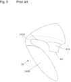
- FIGS. 1 to 3show the stimulation apparatus of DE 10 2013 110 501 A1 which is implemented as a handheld apparatus.
- a pressure fieldis produced made of negative and positive pressures in a chamber (labelled second chamber 4 a ), which is particularly suitable for stimulating the clitoris.
- FIG. 1a front view of a first embodiment of the stimulation apparatus 100 of DE 10 2013 110 501 A1 is explained in detail, wherein, in FIG. 2 , a perspective view and, in FIG. 3 , a cross-section through the stimulation apparatus 1 of a first embodiment of DE 10 2013 110 501 A1 are shown.
- Said stimulation apparatus 1 ais a preferably portable electric or small device which has a housing 8 a , a pressure field generation device 2 a , operating elements 71 a , a display 72 a , an on/off switch 74 a , a bushing 75 a , an optional battery 76 a and optional illumination 9 a.
- the housing 8 ais preferably implemented in such a way that it can be held with one hand and it does not have any sharp or pointed edges.
- the housing 8 acan consist of plastic, for example polycarbonate (PC) or acrylonitrile butadiene styrene (ABS).
- PCpolycarbonate
- ABSacrylonitrile butadiene styrene
- the gripping regions or even the entire housingcan be supplemented by or formed from a haptically advantageous silicone.
- the housing 8 ais preferably formed to be at least water-repellent or splash-proof, for example protection class IP 24 .
- Such a housing 8 a resembling the shape of a cuboid having an extension or the shape of a traditional telephone receivercan also be held by hand, much like a telephone receiver.
- the housingis at least extensively enclosed by the hand, which represents a non-ergonomic handheld position.
- the result of this with such conventional housingsis the requirement that these have to be formed in such a way that they have a sufficiently large size in order to allow them to be enclosed by the hand.
- the external periphery (for example measured in the middle and in the peripheral direction) in the housing 8 a of the prior artis more than 14 cm in order to allow it to be enclosed by the hand and thus to hold the apparatus above the erogenous zone to be stimulated.
- the housing 8 ais deemed to be bulky.
- the size of the housingdisadvantageously results in an increased material cost, an increased weight and also increased tool costs, for example for an injection moulding tool for larger plastic parts.
- the operating elements 71 awhich are shown in FIGS. 1 to 3 serve to set the type of operation of the device, i.e. to set the modulation pattern of the pressure field.
- the operating elements 71 acan be implemented, for example, as at least one push button, as at least one rotation switch or as at least one touch-sensitive switch.
- the operating elements 71 acan provide an optical feedback for activation, for example by means of light diodes (LEDs) integrated in the switch.
- LEDslight diodes
- An optional display 72 aprovides information to the user about the device state and/or setting state.
- the display 72 acan be formed, for example, from a plurality of light diodes, or as an LCD display.
- the displayed informationcan be, for example, the charging state of an optional battery or the current setting of the modulation pattern.
- the on/off switch 74 aserves to activate and deactivate the stimulation apparatus 1 a .
- This on/off switch 74 acan be, for example, a push button, which switches the stimulation apparatus 1 a on or off by being pressed for a longer time, or an engaging sliding switch.
- a bushing 75 aserves for the external current supply of the stimulation apparatus 1 via an external plug 73 a , which is connected, for example, to an external network adapter.
- a magnetically inductive transformercan preferably be provided, which allows a transfer of current into the stimulation apparatus 1 without an electrically conductive contact.
- the stimulation apparatus 1 aadditionally has a battery, for example a nickel-metal hydride battery (NiMH) for wireless operation.
- NiMHnickel-metal hydride battery
- a longer current supply wirecan also be guided out of the stimulation apparatus.
- the pressure field production device 2 a of an embodiment of DE 10 2013 110 501 A1has a first chamber 3 a inside the stimulation apparatus 1 , a second chamber 4 a for placing on a body part 11 a to be stimulated, and a connection element 5 a , which connects the first chamber 3 a to the second chamber 4 a.
- a drive unit 6 afor example an electric motor, drives the first chamber 3 a via an axis 61 a and by means of an eccentric cam 62 a (or additionally by means of a connecting rod) in such a way that the volume of the first chamber 3 is changed correspondingly to the rotation of the axis 61 a of the drive unit 6 a.
- a control devicecontrols the drive unit 6 a , the operating elements 71 a and the display 72 a .
- the control device and the drive unit 6 aare supplied with current by the internal battery 76 a and/or the external current supply 73 a.
- An optional lighting device 9 ais provided on or in the housing 8 a .
- the lighting device 9 apreferably serves to illuminate the inside of the second chamber 4 a .
- the lighting device 9 acan either be switched on by the user or, when activating the stimulation apparatus 1 a , is activated automatically.
- the lighting device 9 acan be formed from the energy-saving light diodes.
- the lighting devicecan, for example, serve as an orientation aid for the user of the stimulation apparatus 1 a in the dark or as additional optical stimulation.
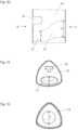
- the longitudinal axis 80 a of the housing 8 a(which extends from the upper end of the housing to the lower end of the housing 8 ), the alignment axis 81 a of the preferred direction of the media flow when operating the drive unit 6 a , the axis or drive shaft of the motor axis 82 a , and the opening plane 83 a of the opening 42 a of the second chamber 4 a are drawn in to illustrate the geometry of the housing 8 a.
- the angle of intersection ⁇ between the longitudinal axis 80 a and alignment axis 81 ais about 90 degrees.
- this kind of arrangementis called an L-shaped arrangement in the following.
- the opening plane 83 ais arranged to be virtually parallel to the longitudinal axis 80 a of the housing 8 .
- the front side of the stimulation apparatus 1 ais called a different side from the one in the stimulation apparatus 1 according to the invention (cf. FIG. 7 to 17 , for example).
- the user of the deviceWith the intended use of the stimulation apparatus 1 a of DE 10 2013 110 501 A1 for stimulating the clitoris, the user of the device now has to pull the opening 42 a over the clitoral glans so that it fits exactly, and place the edge of the opening 42 a on the skin surrounding the clitoral glans with a desired degree of tightness (whereby a gap between the affected area of skin and the edge of the opening, for example, can remain).
- the userwill often want to exactly proportion the contact pressure of the stimulation apparatus 1 a on the skin surrounding the clitoral glans (which is very sensitive), for example, depending on the state of arousal, wherein the weight of the stimulation apparatus 1 a has to be delicately cushioned by the gripping hand.
- the stimulation apparatus 1 amust also be balanced above the virtually point-shaped clitoral glans, which is difficult because of the centre of mass of the stimulation apparatus 1 a , which is arranged to be laterally offset relative to the clitoral glans in the longitudinal direction of the housing 8 a .
- the userhas to compensate not only the total weight, but also the tilting moment of the housing 8 a . This is also seen as disturbing or not ergonomic.
- the stimulation apparatus 1 ais also seen as too heavy and too large.
- the housingis comparatively bulky or large in terms of the preferred usage, since the stimulation apparatus 1 a is used between or on the labia of the woman in spatially confined surroundings. For example, the user often has to stretch out both legs when using the stimulation apparatus which makes the accessibility of the clitoral glans yet more difficult since the thighs are virtually parallel.
- the housing 8 areceives vibrations or oscillations that are generated because of the movement of the eccentric cam by means of the electric motor. These oscillations have a preferred direction that is perpendicular to the axis 82 a and parallel to the alignment axis 81 a .
- the wall 41 a of the second chamber 4 avibrates or oscillates, said second chamber 4 a abutting on the skin surrounding the clitoral glans with its front edge, in the direction of the body of the user, along with the housing, wherein these additional vibrations or oscillations are often unwanted.
- the apparatus 8 acan be regularly seen as loud during operation.
- U.S. Pat. No. 5,377,701 Aalso discloses a vacuum apparatus having a housing that is held in the manner of a pistol grip.
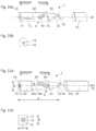
- FIG. 4a front view of the first embodiment of the stimulation apparatus 1 b is shown having an appendage 140 b in a straight position, wherein furthermore, in FIG. 5 , a side view of the stimulation apparatus 1 is shown having the appendage 140 b in an angled position and, in FIG. 6 , a cross-section through the stimulation apparatus 1 b of the first embodiment of DE 20 2015 105 689 U1 is shown.
- the first embodiment of the stimulation apparatus 1 bis a preferably portable electric or small device which has a housing 8 b , a pressure field generation device 2 b , an optional on/off switch 74 b and an optional lighting device 9 b.
- the housing 8 bis preferably implemented in such a way that it can be held with one hand and it does not have any sharp or pointed edges.
- the housing 8 bcan consist of a plastic, for example polycarbonate (PC) or acrylonitrile butadiene styrene (ABS).
- PCpolycarbonate
- ABSacrylonitrile butadiene styrene
- the gripping regions or even the entire housingcan be supplemented by a haptically advantageous silicone or consist of this.
- the housing 8 bis preferably formed to be at least water-repellent or splash proof, for example protection class IP 24 .
- the dotted line in FIG. 5further specifies an optional side edge of the housing 8 b.
- the optional on/off switch 74 bserves to activate and deactivate the stimulation apparatus 1 b .
- This on/off switchcan be, for example, a push button which switches the stimulation apparatus on or off when pressed for a long time, or an engaging sliding switch.
- the stimulation apparatus 1 bcan be switched on and off by remote control.
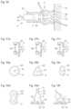
- the pressure field generation device 2 b of a first embodimenthas a first chamber 3 b inside the stimulation apparatus 1 b , a second chamber 4 b for placing over a body part 11 b to be stimulated, and a connection element 5 b which connects the first chamber 3 b to the second chamber 4 b.
- a drive unit 6 bfor example an electric motor, drives the first chamber 3 b via an axis 61 b and by means of an eccentric cam 62 b (or alternatively by means of a connecting rod) in such a way that the volume of the first chamber 3 b can be changed to correspond to the rotation of the axis 61 b of the drive unit 6 b.
- the alignment axis 81 b of the opening 42 b of the second chamber 4 bis also arranged at a right angle to the longitudinal axis 80 b of the housing 8 b .
- the angle of intersection 3 between the longitudinal axis 80 b and the alignment axis 81 b hereis about 90 degrees and constitutes an L-shaped arrangement.
- the opening plane 83 bis arranged to be virtually parallel to the longitudinal axis 80 b of the housing 8 b.
- the housing 8 balso has the same disadvantages which were previously described in more detail with reference to the housing 8 a of DE 10 2013 110 501 A1.
- a control devicecontrols the drive unit 6 b , optional control elements 71 b and at least one optional display 72 b .
- the control device and the drive unit 6 bare supplied with current, for example by the internal battery 76 b and/or the external current supply 73 b.
- the stimulation apparatus 1 of DE 20 2015 105 689 U1, depicted in FIG. 4 to 6further has at least one appendage 140 b .
- This appendage 140 bwhich is preferably a component of the housing 8 b , is optionally able to be moved or bent relative to the housing part in which the pressure field generation device 2 b is contained.
- the appendagecan be angled or even rotated by means of a joint 141 b .
- the joint 141 bcan be formed, for example, as a plastically deformable plastic part, as a setting joint or as a hinge.
- the appendage 140 bshows an example of a bent position of the appendage 140 b relative to the section of the housing 8 b of the stimulation apparatus 1 in which the pressure field generation device 2 b is contained.
- the appendagecan also be formed to be rigid or immovable.
- the appendage 140 bis preferably a stimulation means for inserting in the human body, for example in the vagina or other bodily orifices as well.
- the appendage 140 bis formed as a conventional dildo, for example.
- the appendagecan be formed in such a way that it is adjusted to the human anatomy of a different bodily orifice, for example to the mouth.
- the appendage 140 bcan be formed in such a way that it can also be used as a hand grip in order to hold the stimulation apparatus 1 b .
- holding the apparatus 1 b on the appendage behind a jointis impractical since the joint impedes metering of the corresponding forces.
- the stimulation apparatus 1 bhas a holding position in the manner of a pistol grip which is inconvenient and also disadvantageous, as is described above in more detail.
- the appendage 140 bcan optionally have a vibration apparatus 142 b which can be switched on or controllable.
- the vibration apparatus 142 bshifts the appendage in mechanical oscillations which support the direct stimulation effect of the appendage 140 b.
- the appendage 140 bis optionally applied to the section of the housing 8 which receives the pressure field generation device 2 b in such a way that the (entire) housing 8 of the stimulation apparatus 1 b is formed to be consistent.
- the housing 8creates the impression that it is formed as one piece or one part, for example by means of the flexible and/or seamless connection elements of the housing 8 .
- the housing 8 b incl. the appendage 140 bcan have a silicone covering.
- the stimulation apparatus 1 bcan be held or even inserted into bodily orifices. If the appendage 140 b , as is shown in FIG. 5 , is bent, for example after insertion, the opening 42 b can be guided in this way to the body part 11 b to be stimulated. In this bent position of the stimulation apparatus 1 b , both a direct and indirect stimulation of at least one erogenous zone of the body can take place simultaneously.
- the body part 11 b to be stimulatedcan be located between the appendage 140 b and the pressure field generation device 2 b .
- an optional lighting device 9 bcan be provided on or in the housing 8 b .
- the lighting device 9 bpreferably serves to illuminate the inside of the second chamber 4 b .
- the lighting device 9 bcan be either switched on by the user or can be automatically activated when the stimulation apparatus 1 b is activated.
- the lighting device 9 bcan be formed from energy-saving light diodes, for example.
- the lighting devicecan serve, for example, as orientation aids for the user of the stimulation apparatus 1 b in the dark or as additional optical stimulation.
- the stimulation apparatuses of DE 10 2013 110 501 A1 and DE 20 2015 105 689 U1additionally have the common disadvantage that there is far too much dead space or unused volume inside the respective housing 8 a and 8 b because of the basic design described above. Thus, these apparatuses are implemented in a comparatively voluminous and correspondingly large manner.
- the housing sizefurther leads to an increased material expenditure for the housing.
- the object underlying the inventionis to specify an optimised stimulation apparatus which is more ergonomic.
- the ergonomics of the stimulation apparatusrelate, for example, to the aspects of weight, volume, battery life, the holding position of the hand, compactness, handling, comfort during use, suitability for use and transportability of the stimulation apparatus according to the invention.
- a stimulation apparatus for the clitoriscomprising the following: a pressure field generation device having a drive unit and having a hollow space, wherein a pressure field made of temporally alternating negative and positive pressures can be generated in the hollow space by means of the drive unit by a change in volume of the hollow space, wherein the hollow space has an opening for placing over the clitoris, a control device, which can control the drive unit, and a sensor device, which can detect when the stimulation apparatus is in the vicinity of the clitoris or which alternatively can detect contact of the stimulation apparatus with the clitoris and which can emit an activation signal to the control device in the event that a proximity or contact of this kind is detected, and wherein the control device is designed in such a way that the drive unit is activated when an activation signal is present, and wherein the pressure field generation device, the control device, and the sensor device are received in a housing of the stimulation apparatus, and wherein the stimulation apparatus is embodied as a portable
- the stimulation apparatusis advantageously thus activated only in the case in which the clitoris is located in the vicinity of the opening of the stimulation apparatus or covers this opening.
- the batteryis thus advantageously protected, since the stimulation apparatus is not operated continuously after being switched on, as is provided in the prior art, but instead is operated only when it is possible to act on the clitoris.
- the stimulation apparatusis usually switched on and only then moved toward the clitoris.
- the noise generated in particular by the drive unit in the hollow space of the stimulation apparatuscan propagate outwardly, undamped, through the opening of the hollow space, wherein this can be seen to be disruptive.
- the drive unit of the stimulation apparatusis activated only when the opening of the stimulation apparatus is obscured or covered. Consequently, the noise from the hollow space of the stimulation apparatus is heavily damped outwardly.
- the period of time for which the stimulation apparatus is in operationis reduced. As a result, the noise level of the stimulation apparatus perceptible by the user is advantageously reduced.
- the sensor deviceis a capacitive, acoustic, or optical sensor, preferably a proximity sensor, which is designed in such a way that it is possible to detect when the apparatus is moved toward the clitoris, with the clitoris in front of the opening.
- Thishas the advantage that a defined measurement region can be provided, within which the presence or absence of the clitoris can be reliably detected.
- An acoustic sensor or preferably an acoustic proximity sensorcan operate for example by the known ultrasound propagation measurement principle.
- An optical sensor or preferably an optical proximity sensorcan operate for example by the known infrared measurement principles.
- a capacitive sensorcan operate by the known capacitive measurement principles.
- a capacitive sensorthe following is/are measured: a change in capacitance at a measurement electrode, a capacitance at the measurement electrode, or the change in capacitance and at the same time the capacitance at the measurement electrode.
- a measurement signalis generated, which is representative for the distance of a surface from the measurement electrode.
- activation signalcan preferably be generated by a comparison of the measured variables with a threshold value, which activation signal indicates whether or not the clitoris has reached the vicinity of the stimulation apparatus beyond a predetermined measure.
- a capacitive sensorfor example can comprise at least one measurement electrode.
- the capacitance at the measurement electrodeis dependent on how far away a surface is from the measurement electrode or whether a surface is placed against the measurement electrode.
- a surfacecan be a surface of an object, such as the surface of the clitoris.
- the surface of the clitoris and the surface of the measurement electrodecan be considered fundamentally as two opposite surfaces of a capacitor.
- the capacitance of this capacitoris dependent on various factors, in particular the distance between these surfaces.
- the capacitive sensorcan be set in such a way that it transmits the activation signal to the control device for example if a predetermined threshold value of the capacitance and/or the change in capacitance is exceeded or undershot.
- the capacitive sensorcan additionally comprise a (preferably adjustable or programmable) control logic, which generates or calculates the activation signal from a measurement value obtained from the measurement electrode.
- a reference measurement electrodecan be provided in order to improve the measurement accuracy.
- a guard electrodecan be provided in order to avoid interfering effects.
- a plurality of measurement electrodes, for example two measurement electrodes, of the capacitive sensorcan be provided, wherein the capacitive sensor can be formed in such a way that it outputs the activation signal only if a change in capacitance and/or capacitance lying above a predetermined threshold value are/is measured simultaneously at both measurement electrodes. The reliability of the sensor devices thus improved.
- the sensor devicecan be configured alternatively as a UWB sensor unit.
- UWB sensor unita particularly high content of information with regard to the characterising physical measurand of the body can be obtained advantageously. For example, a distinction can thus be made between a human body and an object.
- a spectral power density of the UWB sensor unitis preferably at most ⁇ 41.3 dBm/Hz EIRP (Equivalent Isotropic Radiated Power), such that interference with other devices operated at frequencies between 30 MHz and 15 GHz can be avoided advantageously.
- EIRPEquivalent Isotropic Radiated Power
- the UWB sensor unitis intended to be operated at a mean frequency which varies discreetly within a predefined frequency range.
- the UWB sensor unitis preferably excited here discreetly in the form of a pulse-like excitation thereof, wherein the mean frequency successively assumes various, discrete values in the predefined frequency range.
- Frequency intervals between two successive excitation frequenciespreferably assume different values so as to satisfy the provisions of regulating authorities particularly effectively.
- a “mean frequency” of the UWB sensor unitshall be understood in this context in particular to mean a frequency that constitutes an arithmetic mean of two frequencies at which a spectral power density is reduced relative to a maximum spectral power density of the UWB sensor system by approximately 6 dB, preferably 10 dB.
- the mean frequency of the UWB sensor unitBy varying the mean frequency of the UWB sensor unit, the information content with regard to the characterising physical variable or vicinity of the clitoris can be increased by measurements in different frequency ranges, thus making the sensor device more reliable.
- the UWB sensing unitis intended to be operated at a mean frequency varying periodically within a predefined frequency range.
- the frequency rangecan be scanned by a continuous variation of the mean frequency. It is advantageous, however, if the UWB sensor unit is excited in an excitation sequence starting from a lower limit of the frequency range with discrete values of the mean frequency, wherein the mean frequency is increased in steps until an upper limit of the frequency range is reached, with this excitation sequence being repeated periodically.
- the sensor devicepreferably has a coplanar antenna.
- a “coplanar antenna”shall be understood in this context to mean in particular an antenna that is formed by strip conductor elements known per se, which are arranged in a plane on a dielectric carrier.
- the coplanar antennacan preferably be formed as a patch antenna or spiral antenna. In principle, however, the use of other designs appearing expedient to a person skilled in the art is also conceivable.
- An antenna of this kindcan be mounted advantageously and in a simple manner inside the housing in the vicinity of the opening. By equipping the sensor device with a coplanar antenna, the concentration of a sensitivity range of the sensor device to a certain measurement region in front of the opening can further advantageously be achieved.
- a coplanar antenna of this kindcan also be formed in an annular manner and can be arranged around the hollow space according to the invention.
- a coplanar antenna of this kindcan also be used in the case of a capacitive sensor as a measurement electrode.
- the sensor deviceis designed in such a way that it can generate and detect an electromagnetic field, wherein this field is arranged along the alignment axis of the flow in the hollow space according to the invention (this will be explained in greater detail further below) and in front of the opening of the hollow space.
- the sensing unitis designed in such a way that, alternatively or additionally to that described above, it can detect contact between a wall, which forms the opening, and the skin of the clitoris.
- Thiscan be implemented for example by means of a conductivity measurement between two electrodes provided in the wall.
- a sensor of this kind with a capacitive measurement principleit is also conceivable if the measurement region is very small.
- Thishas the advantage that contact between the body and the stimulation apparatus can be detected by means of a simple solution, in such a way that only contact of the skin with the wall leads to activation of the drive unit. The noise from the hollow space is thus damped to an even greater extent, since the drive unit is only energised if the hollow space is at least largely closed.
- a stimulation apparatuswhich comprises the following: a pressure field generation device having a drive unit and having a hollow space, wherein a pressure field made of temporally alternating negative and positive pressures can be generated in the hollow space by means of the drive unit by a change in volume of the hollow space, wherein the hollow space has an opening for placing over the clitoris, a control device, which can control the drive unit, wherein the hollow space has a wall made of a flexible material, the wall forming the opening of the hollow space, and wherein the stimulation apparatus has a heating element used to heat the wall of the stimulation apparatus, wherein the pressure field generation device, the control device, and the sensor device are received in a housing of the stimulation apparatus, wherein the stimulation apparatus is embodied as a portable hand-held device.
- the part of the housingi.e. the wall forming the opening to be placed over the clitoris
- the temperature of the housing partcan thus be adapted or approximated to the temperature of the skin, whereby the placement of the housing part is considered to be less disruptive.
- the clitoral regionis in particular sensitive to temperature differences.
- the wall or the housing partcan be designed with a heating element in the form of a semiconductor of high electrical resistance which is integrated as an extended electrical conductor on or in the plastic material of the housing part itself.
- a potential differenceis applied to this semiconductor, a current flows, the losses of which heat the conductor and consequently the wall by way of heat conduction.
- the electrical conductorcan be contacted with the control device.
- This electrical contactcan be implemented for example via magnetic connectors with permanent magnets.
- the heating elementis thus exchangeable with the head.
- the heating elementis received in the wall or is arranged in the housing in the immediate vicinity of the wall.
- the heating elementcan be thermally insulated in respect of undesired heat conduction, i.e. in the direction of the interior of the stimulation apparatus.
- This thermal heat barriercan be provided for example using glass or mineral wool or a suitable plastics material.
- a charging station or also a case for the stimulation apparatus with a heating element having a negative form of the stimulation apparatuscan be provided in order to heat up the stimulation apparatus from the outside prior to its operation.
- the wallcan be heated by means of inductively generated eddy currents.
- the wallcan be provided for this purpose with a grid and/or with conductor tracks made of a ferromagnetic material that is a good heat conductor, wherein the stimulation apparatus is designed in such a way that eddy currents are induced in these conductor tracks.
- an electric coil for establishing a magnetic fieldcan be provided, which coil is arranged in such a way that the magnetic field can act on the grid or the conductor tracks.
- the wallforms part of the outer wall of the housing, wherein the wall can be embodied exchangeably as the head of the stimulation apparatus.
- the headcan thus be removed in order to make the hollow space according to the invention accessible for cleaning.
- Differently shaped headscan also be used. The hygiene and versatility of use of the stimulation apparatus are thus advantageously improved.
- a stimulation apparatus for the clitoriscomprising the following:
- a pressure field generation devicehaving a drive unit and having a hollow space, wherein a pressure field made up of a plurality of predefined stimulation patterns can be generated in the hollow space by means of the drive unit by a change in volume of the hollow space, wherein the stimulation patterns are made up of temporally alternating negative and positive pressures, and wherein the hollow space has an opening for placing over the clitoris, a control device, which can control the drive unit and which comprises the plurality of predefined stimulation patterns and a random generator, wherein the control device is designed in such a way that the sequence of stimulation patterns is set randomly by the random generator when the drive unit is activated, wherein the pressure field generation device, the control device, and the sensor device are received in a housing of the stimulation apparatus, wherein the stimulation apparatus is embodied as a portable hand-held device.
- the sequence of stimulation patterns according to the inventionis understood in particular to mean a temporal sequence of individual previously stored patterns. However, duration of the individual patterns, the selection of the pattern, and also the intensity of the patterns can also be subsumed. As a result of the random sequence of stimulation patterns according to the invention, habituation effects are avoided, since the user cannot anticipate the patterns.
- a method for stimulation of the clitoris using a stimulation apparatuscomprising the following: a pressure field generation device having a drive unit and having a hollow space, a control device and a sensor device, wherein the hollow space has an opening for placement over the clitoris; said method having the following steps:
- the methodserves solely for sexual pleasure and is not intended for therapeutic or medical purposes.
- a stimulation apparatus for erogenous zoneshaving a housing which is substantially (rod-shaped or) pin-shaped, a pressure field generation device having a drive unit that generates a pressure field made of temporally alternating negative and positive pressures in a hollow space, a control device which controls the drive unit; wherein the housing has a longitudinal axis which extends from a front end of the housing up to a back end of the housing, and an opening for placing over the clitoris is provided in the front end of the housing, and wherein the hollow space is arranged inside the housing and is connected to the opening of the housing.
- the longitudinal axis of the housing of the stimulation apparatusis an imaginary axis that extends from a front end of the elongate housing up to a back end of the elongate housing (which is spaced apart axially relative to this front end).
- the longitudinal axisruns in parallel to the length of the housing.
- the longitudinal axiscan be an axis running in the longitudinal direction relative to the longest extent of the stimulation apparatus.
- the longitudinal axiscorresponds, for example, to the direction of the greatest total extent of the housing.
- the longitudinal axisis also the longitudinal central axis which extends roughly centrally through the stimulation apparatus.
- the longitudinal axisis preferably also substantially an axis of symmetry of the stimulation apparatus or of the housing.
- the housingin terms of its basic shape is formed, for example, to be extensively cylindrical. Switches, bushings or similar small details do not come into consideration when considering the symmetry.
- a housingis then formed to be elongate or stretched out when its length is at least three (3) times or even n times the width and/or height.
- the factor nhas the value four (4), five (5), six (6) or seven (7). The greater the factor n is, the more elongated or stretched out the housing is formed to be.
- the housing of the stimulation apparatus according to the inventioncan thus be said to be configured (formed) in a stretched-out manner if it can be received in an imaginary cylinder whose diameter is, for example, smaller by the factor 3, preferably 4, 5, 6, or 7 than its length.
- the front end of the housingis the end of the housing which is arranged to be adjacent to or over the erogenous zone when using the stimulation apparatus, i.e. it is the “active” end having the opening for stimulation in the stimulation apparatus according to the invention.
- the rear or back end of the housingis the end of the housing which is arranged opposite the front end in the longitudinal direction.
- This back endis, for example, the “passive” end of the housing, i.e. generally, a simple terminating end of the housing.
- Operating elementscan be arranged on the back end.
- a pressure field generation device of the stimulation apparatushas a hollow space having an opening for placing on a body part or on the erogenous zone, preferably over the clitoris.
- the hollow chamberis pulled over the clitoral glans such that the clitoral glans is received in the hollow space.
- This placementcan take place in a sealing manner, or also only in a partial or extensively sealing manner, when, for example, a gap remains open between the wall of the opening and the skin of the erogenous zone.
- the front end of the housingpreferably has a placement region for placing the stimulation apparatus on the erogenous zone.
- the placement regionis characterized by a resting surface which comes into contact with the skin when using the stimulation apparatus.
- the hollow space according to the inventiondefines a volume inside the housing for a medium, for example air. This hollow space is separated from the rest of the inside of the housing by flexible and/or rigid walls.
- the hollow spaceis connected to the opening of the housing.
- the hollow spacehas the opening (of the housing) for placing over the erogenous zone to be stimulated.
- the pressure field according to the inventionis formed in this hollow space, said pressure field having temporally alternating negative and positive pressures relative to a reference pressure, wherein this will be described in more detail later (for example with reference to FIGS. 40 a ) to c )).
- the hollow chamberWhen generating the pressure field, the hollow chamber has a flow system according to the invention which has flows that are temporally alternating and are regularly opposing one another. This is explained in more detail later by FIGS. 21 and 22 .
- the hollow chamber according to the inventioncan have, for example, at least one first chamber and at least one second chamber and at least one connection element that connects the first chamber to the second chamber.
- first chamberfunctionally refers to the part of the hollow space in which the drive device can act upon the hollow space, for example by changing the volume.
- second chamberfunctionally refers to the part of the hollow space which has the opening for placing over the erogenous zone, and in which the pressure field according to the invention can act on the erogenous zone.
- the chambers according to the inventionare thus not respectively structurally completely separated spaces or compartments of the hollow space, but only functional sections of a hollow space.
- the connection elementcan also only represent a marginal tapering or narrowing in the form of an individual outlet opening between the two chambers.
- a pressure fieldcan be generated in the second chamber by the formation according to the invention of chambers that communicate in terms of flow via at least one connection element by changing the volume of the first chamber in a simple manner, said pressure field being temporarily aimed at the region of skin to be stimulated.
- a pressure field in the sense of the inventionis a temporally changing field of media pressures which, at times, has positive pressures and, at times, has negative pressures wherein a negative pressure is a media pressure that lies below the reference pressure, and a positive pressure is a media pressure that lies above the reference pressure.
- the mediumis usually in the form of gas, preferably air, however, alternatively or additionally for example, it can be a fluid medium, water or a commercially available lubricant.
- the chambers according to the inventioncan be filled with the lubricant before using the stimulation apparatus.
- stimulation of the corresponding region of skintakes place by means of a suitable skin-friendly fluid instead of air, which may be desired depending on the individual preference of the user.
- the stimulation apparatuscan also be used underwater with water as the medium (for example in the bath or in the swimming pool).
- the stimulation apparatusis formed to be waterproof. If air is the medium, a kind of air column is moved forwards and backwards in the hollow space according to the invention.
- the reference pressureis usually the pressure surrounding the stimulation apparatus present at the start of usage (i.e. before placing the stimulation apparatus on the region of skin to be stimulated). With the preferred use of the stimulation apparatus with air, the reference pressure is the currently present/prevailing air pressure or the normal pressure.
- the reference pressurecan be approx. 1 bar, wherein, as a result, a negative pressure according to the invention can be 0.7 bar (measured absolutely) or ⁇ 0.3 bar (measured relatively), for example, and a positive pressure according to the invention can be 1.3 bar (measured absolutely) or +0.3 bar (measured relatively).
- the area of skin to be stimulatedis stimulated, on the one hand, in terms of its blood flow, while, on the other hand, it is indirectly stimulated.
- two advantageous effectsare combined.
- the erogenous zone of the person concernedis more sensitive, while, in addition, a kinetic effect is generated that serves to stimulate the erogenous zones, for example sexual arousal until climax.
- the stimulation effectis generated by means of the effect of the pressure field on the surface of the area of skin to be stimulated. In this manner, the stimulation effect created by the pressure field is generated indirectly, i.e. without a solid body, for example a vibrator, directly touching the part of the skin to be stimulated.
- the maximum useable pressureis regularly limited by the maximum resilience of the region of skin to be stimulated.
- an excessive negative pressureparticularly with erogenous zones such as the clitoris, poses the risk of painful injuries.
- Stimulation apparatuses that function exclusively by means of negative pressuresare usually limited to this maximum in their functionality.
- an extended working range of the stimulation-triggering pressure field or effectis created according to the invention by means of the combination of positive and negative pressures, since the working range of the pressure can, from now on, be used in the positive and in the negative range up to a maximum without the danger of an unintentional excess.
- the pressure fieldcan act directly on the target region, wherein the pressure field is influenced for example significantly by the configuration of the at least one connection element and the at least one opening from the connection element into the second chamber, and can thus be adjusted depending on the use of the stimulation apparatus.
- an opening of the connection elementcan lie opposite the body part to be stimulated, preferably directly opposite.
- the pressure field that is generated in the second chamberis generated in the immediate proximity of the erogenous zone, preferably the clitoral glans, and is directed at this.
- connection elementin a stimulation apparatus which is intended for the clitoris, can have an individual passage opening having the effect of a nozzle on the clitoral glans between the first and second chamber.
- the individual passage openingcan be, for example, an individual constriction in the hollow space.
- connection elementcan be formed as a nozzle.
- the nozzleaccelerates the medium when generating the positive pressure of the pressure field.
- the nozzlealso directs the media flow towards the clitoris, when the positive pressure is generated in the hollow space.
- a nozzlecan be formed or shaped as a truncated cone or in a rounded manner for example, as will be described below with reference to several figures.
- connection elementcan consist of several, for example four, passage openings between the chambers, when a larger area of the skin region is to be stimulated.
- the hollow spaceand the second chamber, for example
- the flow systemaccording to the invention.
- the medium or the airis moved forwards and backwards significantly in the chambers or in the hollow space, while an exchange with media or air from outside the system is at least extensively avoided.
- the first chamberis connected exclusively to the second chamber (via or by means of the connection element).
- the temperature of the air in the flow system according to the inventioncan be quickly adjusted to the skin temperature, while the disturbing supply of new (for example cold) air from outside the system, as can be the case with the prior art, inter alia when using vacuum pumps or fans, is avoided.
- drying effectsare avoided, since in a closed system there is little or no removal of stimulation-encouraging fluid, for example bodily fluid.
- the pressure field generation devicehas the advantage of increased hygiene and improved cleaning capability because of the simple construction as a hollow space that is closed (to the rest of the inside of the housing).
- the present inventionavoids valves or pumps/compressors having potential dead spaces and parts that cannot be cleaned.
- the pressure field generation deviceis easy to dean. For example, cleaning the stimulation apparatus can take place in a simple manner by filling the first chamber with a cleaning fluid and activating the pressure field.
- the front part of the hollow space and the second chamberfor example, can be arranged such that they can be exchanged, which also simplifies cleaning of the two chambers.
- the hollow space of the pressure field generation device according to the inventionfor example the chambers according to the invention and the connection element, can be produced to be one part, wherein this consists for example of a single plastic moulding (e.g. rubber or silicone).
- the first chamber, the second chamber and the connection elementcan be embodied to be two or three parts.
- each functional unit of the hollow spaceis a separate component, which simplifies the construction.
- the one bracket of the first chamber, a complementary flexible wall of the first chamber, the second chamber and the connection elementcan each constitute a separate component of the pressure field generation device.
- the construction according to the inventionleads to avoiding complex elements in terms of flow, such as valves, for example, which leads to a simplification of the production.
- the stimulation apparatus according to the inventionthus does not have any valves.
- the stimulation apparatushas a drive unit which controls the hollow space in such a way that a pressure field is generated in the region of the opening of the hollow space, said region serving to stimulate the erogenous zones.
- the stimulation apparatus according to the inventionhas a control unit which controls the drive unit.
- the volume of the first chamberis changed in such a way that the pressure field is formed for stimulation via the connection element in the second chamber.
- the transported volumeis constructively limited by the maximum possible volume change which can be caused by the drive unit.
- the maximum positive or negative pressure the stimulation apparatus can build up in the second chamberis limited due to the dimensions of the components of the pressure field generation device and the drive.
- the maximum positive or negative pressurecan be limited to an amount that minimizes or rules out any risk of injury for the areas of skin to be stimulated.
- a safety valvethat is usual in the prior art, or a manual intervention in the stimulation process by the user, such as the opening of a release valve, is for example rendered unnecessary.
- the variation over time in the pressure field or the modulation of the pressure field by the control deviceis controlled largely or completely automatically.
- the modulation of the pressure fieldsuch as intensity, time profile or sequence
- the variation over time in the pressure fieldcan have a regular or recurring (stimulation) pattern, such as pulses at a predetermined cycle rate or regularly alternating pulse sequences.
- stimulationrecurring
- the complexity of using the stimulation apparatusis low, when compared with conventional (medical) vacuum stimulation apparatuses.
- the stimulation pattern of the stimulation apparatuscan be individually configured by the user during or before operation.
- the modulation patterncan be generated and changed by means of a voltage or current control of an electric motor by adjusting and/or varying the number of revolutions of the electric motor.
- the number of revolutionsis consequently changed, the number of strokes of an eccentric cam which is mounted on the shaft changes, as well as the number of strokes of the corresponding flexible wall.
- the opening of the housing and the hollow spaceis arranged in such a way that the longitudinal axis of the housing penetrates the opening of the hollow space.
- the imaginary longitudinal axis of the housingintersects an imaginary surface which is spanned by the inside of the opening or a surface which is surrounded by the front or outermost edge of the opening of the housing.
- This front edgepreferably serves for placement on the skin.
- This imaginary surfacecan be formed to be planar or flat (for example as a planar circular surface or a planar oval surface) or curved (for example concavely).
- the large-volume pistol housing of the generic type (including corresponding dead volumes) or the conventional large-volume housingis replaced by an L-shaped arrangement, by an elongate, compact, preferably pin- or rod-shaped housing which can be held and guided by the operating person in the manner of a highlighter or pen.
- the opening according to the invention of the stimulation apparatusis provided on the “active” end, similar to with a pen.
- the inventorshave recognised that the stimulation effect can be varied significantly by the placement angle and the pressing pressure.
- the pressure ratios inside the hollow spaceclearly vary. For example, measurements of the inventors have shown that the maximum negative and positive pressures inside the hollow space are more than 30 or 50 times greater in the event of a completely sealed placement of the opening than when the opening is not placed very tightly, for example with a small gap facing outwards.
- the usercan set the intensity of the stimulation effect by means of the position of the placement of the opening over the erogenous zone or by means of the inclination of the stimulation apparatus, without here having to carry out (distracting) adjustments, for example, in terms of the modulation pattern on the device by means of operating elements. For example, it is regularly the wish of the user that the intensity of the stimulation effect increases during the course of the use of the stimulation apparatus.
- the handling of the housing and, in particular, the positionability of the opening of the hollow spacealso play an important role when adjusting the intensity of the stimulation effect during use.
- the arrangement according to the invention having an elongate, pin-shaped housing shapefacilitates the overall stimulation effect of the pressure field during use, since the intensity of the stimulation can now clearly be adjusted in a more delicate manner, according to the respective current requirement of the user.
- the placing angle of the openingcan be manually set in a delicate manner relative to the erogenous zone or skin surface because of the housing design according to the invention, since the placing angle can be determined all the more precisely, the longer the housing is.
- the housingcan be formed to be smaller.
- the housingit is thus no longer necessary to form the housing to be so large, in particular in the peripheral direction (and also in the longitudinal direction), that it is possible to enclose it by hand. That is to say, the periphery of the housing no longer has to be so big in the longitudinal direction, as is the case with conventional telephone receiver style housings with an L-shaped arrangement, in order to allow a one-sided, comfortable grip with the hand, but rather the periphery of the housing according to the invention can dearly become smaller, since guiding the stimulation apparatus according to the invention between thumb and forefinger, for example, is sufficient.
- an elongate, compact and lighter housingcan also be aligned more easily relative to the centre of mass of the housing, and, in addition, the housing can also come to rest in the hand in the crook between thumb and forefinger, whereby the weight of the housing can come to rest at least partially on the hand.
- guiding the stimulation apparatuscan also take place by means of holding the longitudinal housing on its back end (i.e. similar to holding a walking stick, which has a pommel). This is also a comfortable holding position for the hand, in particular when the anatomical conditions of the user are taken into consideration. Such a handling of the stimulation apparatus was, up until now, not possible with the L-shaped arrangements of the prior art.
- a pommel or a thickening(which is ball-shaped, for example) can be provided for this purpose on the back end. In this way, a more delicate and more relaxed guiding of the stimulation apparatus is also made possible.
- the stimulation apparatuscan also be guided in such a way that contact of any other housing parts with the skin can be avoided.
- the stimulation apparatus according to the inventioncan also be formed or shaped to be more compact.
- the housingis formed to be elongate in the shape of a pin or in the shape of a rod in such a way that it can be guided manually in the manner of a pen for placement over the erogenous zone, in particular the clitoris (or clitoral glans).
- thisoffers the advantage that the actuation of the elongate stimulation apparatus that is shaped like a rod or pin, for example, is more trusted by the user as a result of previous practice (for example with a pen) and can be carried out in a more ergonomically simple manner.
- a stimulation apparatuswherein the opening defines an opening plane that forms an angle with the longitudinal axis of the housing that is greater than about 30 degrees (alternatively greater than 45 degrees), preferably between about 35 and about 65 degrees (alternatively: 40 to 50 degrees), in particular between about 55 degrees and about 65 degrees, or greater than about 80 degrees, in particular about 90 degrees.
- the opening according to the inventionis detached, for example at a pointed angle relative to the longitudinal axis of the stimulation apparatus.
- This angled arrangement of the opening of the hollow spaceis advantageous since it takes the female anatomy into consideration and allows a more relaxed and more comfortable handling.
- the holding arm of the usercan be bent more sharply.
- the stimulation apparatuscan be held in a steeper or vertical position, which simplifies balancing of the stimulation apparatus over the clitoris, since, among other things, the tilting moment is smaller.
- the opening planeis formed to be perpendicular or approximately perpendicular to the longitudinal axis, which is also advantageous for the manipulability of the apparatus.
- the opening of the housingis arranged in such a way that the longitudinal axis of the housing penetrates (through) the opening of the housing.
- a housing that has been formed according to the geometric principle aboveis still more delicate and intuitive to handle.
- the “active” end, which serves for stimulation, in the longitudinal axis of the housingwhereby the “rotation and pivot point” of application is easier for the user to ascertain.
- the housing designis simplified since the housing can now be formed asymmetrically (in terms of length) for example, whereby the production becomes more cost efficient.
- a stimulation apparatuswherein the hollow space can be controlled by means of the drive unit or can be supplied with forces in such a way that a pressure field that preferably acts in the direction of the longitudinal axis of the housing is generated in the hollow space, said pressure field being aligned, by means of the opening of the hollow space, with the erogenous zone for the stimulation thereof.
- the pressure fieldis aligned with the longitudinal axis of the stimulation apparatus, whereby an accurate and delicate positioning of the stimulating pressure field is advantageously facilitated.
- an “aiming” for a target region or the erogenous zone along the elongate housingis again facilitated and can take place more intuitively.
- the hollow spacecan be set up by means of the pressure field in such a way that the longitudinal axis of the stimulation apparatus intersects or penetrates the pressure field.
- a housing formed according to the geometric principle above having the hollow spaceis more delicate and intuitive to handle.
- a stimulation apparatuswherein the housing has a central section, that is designed for holding the stimulation apparatus with one hand, adjacent to the front end in the longitudinal direction, said section being formed and arranged to extend along the longitudinal axis and in the peripheral direction around the longitudinal axis, in particular only across a peripheral section.
- the central sectioncan comprise a haptically advantageous material, for example rubber or silicone, so that it can be gripped better.
- the central sectiondirectly or immediately connects to the front end, whereby the elongate stimulation apparatus can comprise a haptically advantageous material not only on the front end, but also in the section behind it. This takes into consideration that, in the central section, there is an increased probability that this can also come into contact with other parts of the skin, for example the thighs or the labia of the user.
- the stimulation apparatusis formed to be haptically (and tactilely) and ergonomically advantageous.
- the central sectioncan also be formed, in particular, only across a peripheral section, which saves material and coating expenditure, for example.
- the central sectioncan be provided only for the resting surface of the finger.
- a stimulation apparatuswherein the central section extends over at least 30%, preferably over at least 40%, further preferably at least 50% of the axial extent of the longitudinal axis 80 and optionally up to a maximum of 70% of the axial extent of the longitudinal axis.
- a stimulation apparatuswherein the stimulation apparatus has a centre of mass that is arranged closer to the back end than the front end, as considered in the longitudinal direction.
- the centre of massis closer to the back end, as considered in the longitudinal direction, than to the front end.
- the front (lighter) endfor example, can be moved in an easier and more delicate manner, when the (heavier) back end rests on the outer surface of the hand or in the inner surface of the hand.
- a stimulation apparatuswherein the longitudinal axis represents an approximate axis of symmetry of the housing.
- a symmetryleads to advantages in terms of production, for example it is possible to use the parts for the housing multiple times (for example, half shells can be used); or the construction of the product is simplified.
- a housing having such an axis of symmetryhas a centre of mass which can be arranged on or adjacent to the longitudinal axis, which, in turn, improves the ability of the housing the be handled and balanced.
- a stimulation apparatuswherein the hollow space has a wall, which consists of a flexible material, and the wall forms the opening of the housing, and the wall on the front end also forms the outer wall of the housing.
- this wallpreferably forms the resting surface of the housing on the skin.
- the direct (front) contact surface of the wall of the opening of the hollow space with the corresponding part of skinis formed from a flexible (haptically and tactilely advantageous) material, such as silicone or rubber, for example, but the outside of the front end of the housing of the stimulation apparatus according to the invention is also correspondingly formed.
- a flexible (haptically and tactilely advantageous) materialsuch as silicone or rubber
- the outside of the front end of the housing of the stimulation apparatus according to the inventionis also correspondingly formed.
- the outer labiacan be brought into contact with the (outer) wall of the front end, when the stimulation apparatus is placed over the clitoris.
- a stimulation apparatuswherein the hollow space has an alignment axis which is defined by the alignment of the flow(s) of the medium when generating the pressure field (or the positive pressure) in the region of the opening; and the alignment axis intersects the longitudinal axis at an angle which is less than or equal to 50 degrees, preferably less than or equal to 35 degrees; or the alignment axis is arranged substantially in parallel to the longitudinal axis.
- the hollow spacefor example, is formed cylindrically behind the opening of the housing running into the depths of the housing, then the flows, for example, can be directed towards and away from the opening, alternating temporally, along the direction of the central axis of this cylinder.
- the alignment axisis arranged in parallel or having a small (flat) angle in relation to the longitudinal axis of the stimulation apparatus.
- the handling, in particular the kind of delicate alignment of the pressure field generating the stimulation,is thus improved, according to experiments by the inventor.
- a stimulation apparatuswherein the drive unit is an electric motor having a drive shaft or axis; and the central axis of the drive shaft or axis of the electric motor is arranged substantially in parallel to the alignment axis, which preferably aims at the erogenous zone to be stimulated. It is also preferred that the central axis of the drive shaft of the electric motor is arranged in parallel to the longitudinal axis.
- the electric motor and the eccentric cam arranged on the axisis the source of oscillations or vibrations which are aligned substantially perpendicular to the axis because of the unbalance of this arrangement.
- the axis of rotation of the eccentric camoften does not correspond to the main inertia axis.
- the axis of the motorvibrates or oscillates and thus the motor and consequently also the housing do so too, substantially in a direction that is perpendicular or at a right angle to the central axis of the axis of the motor.
- the erogenous zone to be stimulatedis consequently found in the substantial propagation region or in the direction of these oscillations or vibrations.
- the substantial propagation directioncorresponds to the oscillations or vibrations of the axis 81 a .
- these oscillationstransfer to the body of the user via the wall of the hollow space and via the contact surface of the wall, which can disturb the user.
- the alignment axis and the central axis of the axis of the electric motorare aligned to be coaxial to each other, wherein oscillations or vibrations are the least pronounced in this kind of arrangement.
- the alignment axis and the central axis of the axis of the electric motorcan form an angle of the axes relative to each other of ⁇ 30 degrees, preferably ⁇ 15 degrees, wherein tests have shown that, even with the above angle ranges, a perceptible reduction of the pronouncement or strength of the vibrations or oscillations of the opening of the hollow space/housing takes place.
- a stimulation apparatuswherein the pressure field generation device has a flexible wall, which can be displaced by the drive device; and the direction of the displacement of the flexible wall by the drive unit is provided at an angle of preferably >45 degrees ⁇ 90 degrees, in particular 90 degrees, relative to the alignment axis.
- the motor having the eccentric camgenerates unwanted oscillations or vibrations, but also unwanted oscillations or vibrations are generated on the flexible wall of the hollow space. These vibrations or oscillations also have a propagation direction in the direction of the displacement of the flexible wall.
- the previous arrangement according to the inventioncan also again reduce the vibrations or oscillations.
- a stimulation apparatuswherein the pressure field generation device is formed in such a way that it has at least one damping element.
- Such a damping elementis a silicone bearing which is arranged between the eccentric cam and the flexible wall.
- the damping elementcan be a silicone or rubber damper (which is preferably formed in a hollow cylindrical shape in such a way that it can be inserted in screw connections) that is arranged between the fixing points of the pressure field generation device and the complementary suspension bracket of the housing.
- the damping elementcan also alternatively be a sheathing of the motor made of an elastic material.
- the motorcan be wrapped in sponge and fixed in the housing.
- a stimulation apparatuswherein the damping element is arranged between the opening and the electric motor or the flexible wall mechanically or in terms of flow in such a way that vibrations and/or sounds that are generated inside the housing are damped in the direction of the opening.
- the damping elementis preferably a cushion-shaped or cuboid attenuator made of silicone or rubber, which is arranged in the longitudinal direction between the motor (or the flexible wall) and the opening.
- the damping elementhere preferably covers a large part of the cross-sectional area of the housing, as considered in the longitudinal direction, in order to provide an effective damping effect.
- the mechanical oscillations or vibrationsi.e. those transferred via the solid body, are damped in the longitudinal direction of the housing.
- the damping elementcan here be inserted or arranged in particular adjacent to the front end of the housing in the internal space of the housing or, for example, between the front end and the central section of the housing.
- the damping elementcan be used as a damping element in terms of flow, then the acoustic oscillations in the medium, which are generated in the first chamber, can be damped (for example, the flexible wall oscillates; in addition, there are unwanted flow sounds on edges or narrow points in the hollow space).
- the damping elementcan be used as a sound damper in terms of flow, wherein the damping element has a channel in which acoustic oscillations, in particular in a frequency range of ten to a few hundred Hertz, are effectively damped (for example by more than 6 dB).
- a stimulation apparatuswherein the damping element has a channel which runs in an S-shape, and/or the channel is coated or lined with a sound-damping material on its inner wall.
- the two measures carried out above of the S-shaped course and the coating having a sound-damping materialserve to improve the sound-damping effect of the damping element. Because of the S-shaped course, a sound wave from the first chamber can no longer outwardly propagate in a straight line and in an undamped manner. Thus, the volume of the stimulation apparatus during operation is reduced.
- the two openings of the S-shaped channelhave opening planes running in parallel to each other.
- a stimulation apparatuswherein the damping element consists at least partially of silicone, vinyl or rubber.
- silicone, vinyl or rubberare materials by means of which the necessary components can be produced cost effectively and in different shapes, while at the same time these materials have good (acoustic and mechanical) damping properties.
- a stimulation apparatuswherein the housing has the central section adjacent to the front end, said central section having at least two gripping surfaces.
- the two gripping surfacescan be used by the user as orientation aids as to how the fingers are to be placed on the housing of the stimulation apparatus.
- these gripping surfacescan also be provided with a rubber coating or a “grip”, in order to improve the hold of the stimulation apparatus or in order to prevent slippage when the stimulation apparatus has become greasy or slippery, for example due to liquids (lubricant, etc.).
- a stimulation apparatuswherein the housing has the central section adjacent to the front end, the central section being formed completely as a gripping section.
- the whole central sectioncan thus be formed as a gripping section, so that the user has a high degree of freedom in how she holds the stimulation apparatus. It is preferred that the central section is therefore formed completely out of silicone or rubber or consists of silicone or rubber, or, on the other hand, the central section is coated completely or in a patterned manner by a material that offers the user a good hold for the hand.
- a stimulation apparatuswherein the central section has an external contour which is formed to be round, oval, of equal thickness or a regular polygon, as considered in the cross-sectional direction or in the cross-sectional plane of the central section.
- the external contours according to the inventionoffer the advantage that they are relatively simple to manufacture and are advantageous haptically.
- an external contour that is of equal thickness in the longitudinal direction of the housing and the central sectioncan be guided easily by hand, since the surfaces fit well into the anatomy of the hand.
- An external contour in the shape of a Reuleaux triangleis therefore particularly preferred, wherein the three outer edges or corners can additionally be rounded off easily.
- materialis saved, since a cylinder having an equal external radius has more wall surface area.
- a stimulation apparatuswherein the front end of the housing consists of silicone or rubber, and is preferably formed exchangeably as the head of the stimulation apparatus.
- An exchangeable front endhas the advantage that it can be easily replaced when closing, or also that cleaning the stimulation apparatus after use is made easier.
- a stimulation apparatuswherein the silicone of the front end is medical silicon having a pressure elastic modulus less than 0.1 N/mm 2 , preferably less than 0.05 N/mm, in particular less than 0.01 N/mm 2 .
- the head of the pressure field generation devicecan consist, in particular, of silicone, preferably of silicone rubber or silicone elastomer, which can be relatively elastic or soft.
- the siliconesare used in common stimulation apparatuses for the clitoris which have an elastic modulus (E-modulus) of more than 0.5 N/mm 2 (or a thrust modulus/G-modulus of more than 0.2 N/mm 2 ) so that they remain permanently stabile and can be permanently fixed.
- E-moduluselastic modulus
- a thrust modulus/G-modulusof more than 0.2 N/mm 2
- G modulusshear modulus
- the silicone materialhas elastic properties which correspond or at least come close to the elastic properties of the human skin and the tissue lying below. As a result of this adjustment of the elastic properties, the silicone head is seen as more pleasant and softer.
- the silicone head according to the inventionconsists of a silicone which has an elastic modulus (E modulus) of less than 0.1 N/mm2. Analogously, this would correspond to a shear modulus (G modulus) of less than 0.04 N/mm2. A yet softer or more elastic material is also seen as even more pleasant.
- E moduluselastic modulus
- G modulusshear modulus
- Corresponding softer silicone headscan be fixed permanently on the stimulation apparatus according to the invention by means of a support piece (that is integrally formed with the silicone head and adhered thereto) or a support body. Several silicone heads can be supplied with the stimulation apparatus 1 for exchange once worn.
- a stimulation apparatuswherein the silicone of the front end has additives, in particular stabilisers or dyes.
- coloured pastescan additionally be added which give the silicone the red colour (for example RAL 3020) or red-violet (RAL 4002) colour.
- a platinum-catalysed addition crosslinkingcan also be used.
- a stimulation apparatuswherein the housing is completely or partially encased by a layer made of silicone, rubber or vinyl.
- the stimulation apparatuscan also be formed to be haptically advantageous in order to facilitate further kinds of handling or holding with the hand.
- a stimulation apparatusin which a cup-shaped (or half-open) cap, which can be applied to or fitted on the housing, such that the cap covers at least the opening of the hollow space, is provided.
- Such a capimproves the transportability and the hygiene of the stimulation apparatus, since the opening of the hollow space is covered. Since the opening of the hollow space is regularly used in the private parts, the cap according to the invention protects the opening, and thus also the hollow space, from dirt ingress. If the front end of the stimulation apparatus is also formed from (soft) silicone, then this end is sensitive towards mechanical loads. Thus, the cap also protects the front end of the stimulation apparatus from mechanical damages.
- the cap according to the inventioncan have a cross-sectional shape which corresponds to the external cross-sectional shape of the housing.
- the cross-sectional shape of the capcan be of equal thickness, round, oval or in the form of a regular polygon.
- a stimulation apparatuswherein the cap according to the invention is dimensioned in such a way that it can be put or placed on the stimulation apparatus up to a stop, such that the front end and the central section are covered (preferably completely) by the cap.
- the opening and the front end of the stimulation apparatuscan be covered and protected by the cap, but also the grip regions, which can also consist of sensitive silicone or are coated with rubber.
- a stimulation apparatuswherein the housing is set up in such a way that it is provided to be waterproof, preferably IP67, and the hollow space of the pressure field generation device is provided to waterproof, preferably IP67, in comparison to the inside of the stimulation apparatus.
- the hollow space in particular, in comparison to the rest of the inside of the stimulation apparatus,is sealed in such a way that it corresponds to the (standardised EU) IP67 specifications.
- Thisis therefore possible with the stimulation apparatus according to the invention, since the hollow space according to the invention has only one single opening to the outside of the housing, and, on the other hand, no opening (for example via a valve) into the (further) housing interior
- IP67no opening (for example via a valve) into the (further) housing interior
- further usage possibilities of the stimulation apparatusfor example in a swimming pool, open up, wherein, because of the relatively high IP classification, the reliability of the apparatus is also ensured.
- all bushings possibly present for the current supplyare to be sealed, for example by means of corresponding plugs which can be inserted in the bushings.
- the hollow space of the pressure field generation devicehas at least one first chamber and at least one second chamber having the opening for placing over the erogenous zone and at least one connection element having at least one opening into the second chamber, wherein the connection element connects the first chamber to the second chamber; and wherein the drive unit can change the volume of the first chamber by displacing the flexible wall in such a way that the pressure field is generated via the connection element in the second chamber, said pressure field serving for stimulation.
- a system having a stimulation apparatus and a bracket for storing and charging the stimulation apparatuswherein the charging bracket has an (inductive) bracket-side charging coil, and the stimulation apparatus has a complementary stimulation-device-side charging coil, and the battery of the stimulation apparatus can be charged by means of inductive coupling of these charging coils when the stimulation apparatus is deposited in or on the loading bracket, wherein the stimulation apparatus does not have any bushing for supplying current.
- a system having a stimulation apparatusas is described above, wherein the bracket-side charging coil and the stimulation-device-side charging coil are arranged in such a way that these are arranged to be adjacent to each other when the stimulation apparatus is deposited in or on the charging bracket.
- the stimulation apparatusis set up without a pistol grip.
- the stimulation apparatusis set up without valves.
- the methods described below in more detailserve for stimulation of erogenous zones for sexual pleasure, therefore the methods do not serve for medical, for example therapeutic, purposes.
- the use of the stimulation apparatus according to the invention as a sex toy for stimulating the female clitorisis proposed according to a further aspect of the invention.
- the female clitorisis a particularly sensitive erogenous zone for the woman, which is why the use according to the invention of an indirect positive pressure stimulation in combination with a negative pressure stimulation for the clitoris seems to be particularly advantageous for stimulating to orgasm or to the sexual high point.
- the stimulation apparatuspreferably in the front end and the central section, is formed uniformly.
- uniformlymeans, in particular, that the transitions between the individual housing sections are formed to be gap-free.
- the transitions from the front end to the central section (and vice versa)are seamless or gap-free, or at least retain their shape. This improves the hygiene and the operability of the stimulation apparatus.
- FIG. 1a front view of an embodiment of a stimulation apparatus of the prior art
- FIG. 2a perspective side view of a stimulation apparatus of the prior art
- FIG. 3a cross-section through a stimulation apparatus of the prior art
- FIG. 4a front view of a stimulation apparatus of the prior art having an appendage in a straight position
- FIG. 5a side view of a stimulation apparatus of the prior art having the appendage in the bent position
- FIG. 6a schematic cross-section through a stimulation apparatus of the prior art
- FIG. 7 aa side view of a stimulation apparatus according to the invention of a first embodiment
- FIG. 7 ba view of the stimulation apparatus according to the invention from FIG. 7 a , from behind;
- FIG. 8 aa side view of a stimulation apparatus according to the invention of a second embodiment
- FIG. 8 ba view of the stimulation apparatus according to the invention from FIG. 8 a , from behind;
- FIG. 9 aa side view of a stimulation apparatus according to the invention of a third embodiment
- FIG. 9 ba view of the stimulation apparatus according to the invention from FIG. 9 a , from behind;
- FIG. 10 aa side view of a stimulation apparatus according to the invention of a fourth embodiment
- FIG. 10 ba view of the stimulation apparatus according to the invention from FIG. 10 a , from behind;
- FIG. 11 aa side view of the stimulation apparatus according to the invention of a fifth embodiment
- FIG. 11 ba view of the stimulation apparatus according to the invention from FIG. 11 a , from behind;
- FIG. 12 aa side view of a stimulation apparatus according to the invention of a sixth embodiment
- FIG. 12 ba view of a stimulation apparatus according to the invention of a sixth embodiment, from the front;
- FIG. 12 ca view of a stimulation apparatus according to the invention of a sixth embodiment, from behind;
- FIG. 13a perspective view of a 3D wireframe model of the sixth embodiment of the stimulation apparatus according to the invention.
- FIG. 14a perspective view of a stimulation apparatus according to the invention of a seventh embodiment with a closed cap
- FIG. 15a perspective view of a stimulation apparatus according to the invention of a seventh embodiment with a cap open forwards;
- FIG. 16a side view of a lying stimulation apparatus according to the invention of a seventh embodiment with an open cap;
- FIG. 17a side view of a standing stimulation apparatus according to the invention of a seventh embodiment without a cap;
- FIG. 18a view of a stimulation apparatus according to the invention of a seventh embodiment, from the front;
- FIG. 19a side view of a gripping part according to the invention of the seventh embodiment.
- FIG. 20a sectional view of a gripping part according to the invention of the seventh embodiment in the transverse direction of the housing
- FIG. 21a schematic cross-section through a pressure field generation device of an aspect of the present invention
- FIG. 22a schematic cross-section through a pressure field generation device of a further aspect of the present invention.
- FIG. 23a cross-section through a pressure field generation device of a further aspect of the present invention in the first state
- FIG. 24a cross-section through a pressure field generation device of the aspect of FIG. 23 of the present invention in the second state;
- FIG. 25a cross-section through the pressure field generation device of the aspect of FIG. 23 and FIG. 24 of the present invention in the third state;
- FIGS. 26 a ) to eschematic cross-sectional views through sections of the hollow space according to the invention
- FIG. 27schematic cross-sectional views through sections of the hollow space according to the invention
- FIG. 28a perspective side view of a pressure field generation device of the stimulation apparatus of the seventh embodiment of the present invention.
- FIG. 29a schematic sectional view through the pressure field generation device according to the invention of FIG. 28 ;
- FIG. 30a sectional view in the longitudinal direction through a damping element of the pressure field generation device of FIG. 28 ;
- FIG. 31a view of the damping element of the pressure field generation device of FIG. 28 , from behind;
- FIG. 32a view of the damping element of the pressure field generation device of FIG. 28 , from the front;
- FIG. 33a perspective view of a section of the hollow space or a first chamber of the pressure field generation device of FIG. 28 ;
- FIG. 34a schematic view of a bracket according to the invention for a stimulation apparatus of an embodiment
- FIG. 35a schematic sectional view of a cup-shaped bracket according to the invention for a stimulation apparatus of an embodiment
- FIG. 36a cross-section through a pressure field generation device of a further aspect of the present invention.
- FIGS. 37 a ), b ) and cschematic cross-sections through a pressure field generation device of a further aspect of the present invention
- FIG. 38 a ) to f )different views from below and the side of further aspects of a second chamber of the present invention
- FIG. 39a block diagram of an aspect of the present invention.
- FIG. 40 a ) to cdiagrams of different patterns of the pressure modulations of the present invention.
- FIG. 41a cross-section through an embodiment of the stimulation apparatus according to the invention.
- FIG. 7 aa side view of a stimulation apparatus 1 according to the invention of a first embodiment and, with reference to FIG. 7 b ), a view of the stimulation apparatus 1 according to the invention of FIG. 7 a ) from behind are explained in more detail.
- FIGS. 7 a ) and 7 b )show an elongate and rod-shaped stimulation apparatus 1 having a housing 8 (for example made of ABS plastic), and a front end 90 , a back end 91 , wherein the stimulation apparatus 1 is formed to be circular in terms of its cross section or in terms of the external contour in its cross-section plane.
- an on/off switch 74is provided, which optionally has a lighting element for displaying the switching state.
- An optional display 72can relay the current setting of the modulation pattern or the strength of the stimulating pressure field.
- a central section 88is optionally coated with silicone, while a gripping surface 89 (and a further gripping surface 89 on the side facing away that is not depicted in more detail) in the form of an elongate oval surface (for example as a Lamé oval) determines the preferred placement position for the finger and ensures a good hold for the finger.
- These gripping surfaces 89can be shown by colour, for example, or an additional rubber coating can be applied on the surface of the central section 88 .
- a cup-shaped cap 85that is complementary to the front end 90 or that fits in terms of shape is formed in such a way that—much like a cap of a pen—it can be placed on the front end 90 .
- the cap 85covers (and protects) the front head or the wall 41 and the opening 42 of the stimulation apparatus 1 in the placed-on state and reaches up to the transition or the intersection of the wall 41 on the front end 90 relative to the central section 88 in the longitudinal direction.
- the outer diameter of the cap 85 in the transverse directionis the same as the outer diameter of the housing 8 in the transverse direction.
- the opening 42 of the stimulation apparatus 1is arranged in the front end 90 , wherein the longitudinal axis 80 penetrates the opening 42 .
- the directions “to the front” and “to the back”are correspondingly shown by the arrows in the Figure.
- the front end 90is the “active” end which is used for the stimulation by means of the pressure field.
- the opening 42is formed to be chamfered or at an angle in relation to the longitudinal axis 80 , which is why the opening plane 83 (which is defined by the outer edges of the opening) is intersected by the longitudinal axis 80 at an angle ⁇ .
- This angleis preferably 60 degrees ( ⁇ 5 degrees).
- the axis labelled with the reference numeral 81depicts the alignment axis 81 of the hollow space 10 of the stimulation apparatus 1 according to the invention.
- the hollow space 10 and the opening 42are formed in terms of flow in the region of the opening 42 in such a way that the pressure field has preferred directions in term of flow (of the forward and backward movement of the medium) at the opening 42 of the housing 8 along the alignment axis 81 in the non-placed state of the stimulation apparatus 1 .
- the on/off switch 74can preferably be formed to be embedded in the housing 8 so that it does not protrude from the housing 8 .
- the longitudinal axis 80is an imaginary line between the front end 90 and the back end 91 , which presently also depicts the axis of symmetry for the basic shape of the housing 8 in FIGS. 7 a and 7 b .
- operating elements 74 , displays 72 or gripping surfaces 89are not taken into consideration, and represent only marginal adjustments of the basic shape of the housing 8 .
- the alignment axis 81preferably intersects the longitudinal axis 80 at an angle ⁇ of about 30 degrees, while the opening plane 83 is arranged at a right angle to the alignment angle 81 .
- the stimulation apparatus 1has a compact, narrowly elongate construction. This leads to weight savings and an ergonomic operability of the apparatus 1 .
- the stimulation apparatus 1 of FIGS. 7 a ) and 7 b )is implemented to be waterproof (IP67). Therefore and because of the simple external shape of the stimulation apparatus 1 , it is easy to clean.
- FIG. 8 aa side view of a stimulation apparatus according to the invention of a second embodiment and, with reference to FIG. 8 b ), a view of the stimulation apparatus according to the invention of FIG. 8 a ) from behind are explained in more detail.
- the second embodimenthas a regular hexagonal housing 8 which has a flat back end 91 .
- this housing 8can be advantageously picked up or put down as well, without it rolling away.
- the housing shapethus serves as roll prevention.
- the opening plane of the opening 42 in the front end 90 of the housing 8is arranged to be at a right angle (cf. angle ⁇ ) to the longitudinal axis 80 .
- the alignment axis 81coincides with the longitudinal axis 80 .
- the on/off switch 74 and the display 72are arranged to be adjacent to the front end 80 .
- the cap 85is formed analogously to the first embodiment and fits correspondingly to the housing shape of the housing 8 of the second embodiment.
- FIG. 9 aa side view of a stimulation apparatus according to the invention of a third embodiment and, with reference to FIG. 9 b ), a view of the stimulation apparatus according to the invention of FIG. 9 a ) from behind are explained in more detail.
- the housing 8 of this embodimentis formed to be somewhat centrally waisted, and tapers correspondingly towards the centre.
- the housing 8thus has a shape similar to that of a dog bone.
- the cross-sectional shape of the housing 8is approximately oval, and is preferably retained with the same width/height ratio across the entire length of the housing 8 . This leads to the housing 8 lying comfortably in the hand, and not easily rolling away if the stimulation apparatus 1 is put down.
- the central section 88forms the gripping surface 89 over its entire surface, wherein this preferably provides a rubbery coating. Furthermore, the central section 88 is formed via wide parts of the housing 8 in the longitudinal direction. In synergy with the waisted shape of the housing 8 , this leads to an ergonomic handling of the housing 8 , since the housing 8 comes to rest in the narrow region in the middle in or on the hand, when the housing 8 is guided in the manner of a writing device. In addition, thumb and index finger rest on the front swelling of the housing 8 in this gripping position, which is more ergonomic.
- the stimulation apparatus 1has the swelling or pommel-like cross-section enlargement on the back end 91 .
- the swelling of the housing 8can have a larger maximum radius in the transverse direction on the back end 91 , like the front swelling.
- the opening 42 of the hollow space of the stimulation apparatus 1has a slightly concave opening plane, since the front end of the opening 42 runs slightly wavy or wave-shaped in the front end 90 of the housing 8 .
- the emerging opening planeis also slightly concavely curved or arched. Such a curvature of the opening plane leads to the opening 42 being able to be placed more pleasantly over the area of skin that is also (slightly) curved or not even, said area of skin surrounding the female clitoral glans.
- the opening plane 42is adjusted in terms of its shape to the anatomy of the clitoris in such a way that the opening 42 can be placed in a form-fitting manner or fitting to the area of the skin which surrounds the clitoral glans without significant pressing pressure.
- the angle of intersection ⁇ of the opening plane 83 with the longitudinal axis 80is determined in terms of the intersection point with the longitudinal axis 80 , and is the smallest possible angle.
- An angle range of about 65 to 75 degreeswas experimentally determined as the optimal angle ⁇ for the use of such a curved opening plane 83 for using on the clitoris 12 .
- the cap 85is formed to be analogous to the first embodiment, and fits correspondingly to the housing shape of the housing 8 of the third embodiment.
- the angle of intersection ⁇ between the alignment axis 81 and the longitudinal axis 81is a pointed angle. Preferably, this is about 3 to 12 degrees, which, after experiments, has generally been proven to be a more pleasant angle range for handling for the user.
- FIG. 10 aa side view of a stimulation apparatus according to the invention of a fourth embodiment is explained in more detail and, with reference to FIG. 10 b ), a view of the stimulation apparatus according to the invention of FIG. 10 a ) from behind is explained in more detail.
- FIG. 10 ashows a housing that is triangular in terms of its cross-section, which is formed to be elongate.
- the external shapeis designed to be of equal thickness in the cross-section direction to save material and weight.
- the on/off switchis realised to be embedded in the back end 91 of the housing 8 so that the apparatus 1 can be placed upright on a table for example, by means of the flat back end.
- the gripping surfaces 89are realised to be elongate ovals, and arranged in such a way that they constitute the support surface of the finger on the housing 8 when the housing 8 is guided in the manner of a writing device.
- the two gripping surfacesare thus arranged to be asymmetrical.
- the gripping surface 89 depicted in FIG. 10 ais provided for the thumb of a left-handed person.
- the gripping surface not depicted in more detailwould be arranged to correspond to the (imaginary) position of an index finger on the other side of the triangle in an elongate oval shape rather than in the direction of the longitudinal axis 80 of the housing 8 .
- the gripping surfacescan be adjusted in terms of their flat arrangement fundamentally to the anatomy of the hand and the finger of the users (particularly preferably after determining whether the present user is right-handed or left-handed).
- the gripping surfaces 89can also be formed as trough-shaped indents in the central section 89 .
- the gripping surfaces 89can have corresponding rubber coatings in order to improve the grip of the apparatus.
- the cap 85 according to the inventionis formed to be analogous to the first embodiment, and fits correspondingly to the housing shape of the housing 8 of the third embodiment and continues the housing shape in the longitudinal direction 80 .
- FIG. 11 aa side view of a stimulation apparatus according to the invention of a fifth embodiment and, with reference to FIG. 11 b ), a view of the stimulation apparatus according to the invention of FIG. 11 a ) from behind are explained in more detail.
- the external shape of the cross-sectionchanges at the transition between the central section 88 to a back section 86 .
- the central section 88is preferably implemented to be triangular in terms of its cross-section, having rounded corners or edges (in particular of equal thickness; alternatively, the central section 88 of this embodiment can also be formed to be round or oval).
- the back section 86is preferably formed to be cuboid or square in terms of cross-section (alternatively, it can be formed to be rectangular or even spherical; the latter leads to forming a ball or button-shaped holding pommel on the back end 91 of the stimulation apparatus 1 ).
- these partsare preferably arranged in the back section 86 of the housing 8 , said parts being heavy or having a high weight, for example the battery.
- the centre of mass MA of the housing 8 of the stimulation apparatus 1is further placed towards the back in the direction of the back end 91 , which leads to better handling.
- the ratio of length A to width B (which is the same as height C) of the housingis preferably ⁇ 3.5 (three point five), in particular a 3.9 (three point nine). Because of this elongate embodiment, the housing 8 can be handled more easily and more ergonomically.
- the display 72is implemented on the back end 91 of the housing 8 in the form of an LED display surrounding the on/off switch.
- the userintuitively associates the display of the switching state with the corresponding on/off switch, and vice versa.
- the fifth embodimentis preferably characterised in that the external contour of the housing 8 changes from the central section 88 to the back section 86 .
- the fifth embodimentis preferably characterised in that the central section 88 has a different external contour to that of the back section 86 .
- the cap 85 of the fifth embodimentis formed to be longer.
- the cap 85 of the fifth embodimentis placed on the housing 8 , then not only the front end 90 is surrounded by the wall 42 , but also the central section 88 .
- the edge 851 of the cap 85abuts on the edge 861 of the back section 86 , when the cap 85 is placed on the housing 8 .
- the stimulation apparatus 1provides a uniform, elongate cuboid impression, on the basis of which it is not immediately recognisable what the purpose is of the apparatus 1 contained. Therefore, in the present discrete, light and compact design of the stimulation apparatus 1 , the stimulation apparatus 1 can be taken in the handbag in a discrete and hygienic manner, for example.
- the angle ⁇ between the plane of the opening 42 of the hollow space and the longitudinal axis 80is about 80 degrees, preferably about 80 to 90 degrees, in particular about 90 degrees.
- the alignment axis 81can further preferably coincide with the longitudinal axis, i.e. these are preferably arranged coaxially relative to each other.
- FIG. 12 aa side view of a stimulation apparatus according to the invention of a sixth embodiment, with reference to FIG. 12 b ), a view of a stimulation apparatus according to the invention of the sixth embodiment from the front, and, with reference to FIG. 12 c ), a view of a stimulation apparatus according to the invention of the sixth embodiment from behind, and, with reference to FIG. 13 , a perspective view of a 3D wireframe model of the sixth embodiment of the stimulation apparatus according to the invention are explained in more detail.
- this sixth embodimentis similar to the fifth embodiment, to which reference is made.
- An elongate housing 8which is presently depicted standing upright in FIG. 12 a , extends along a longitudinal axis 80 and has the opening 42 of a second chamber 4 on the front end 90 . Furthermore, the housing on the front end 90 has a (flat) resting region 43 which comes into contact with the skin.
- Latching closures 862are provided for fixing the cuboid and hollow cap 85 , said latching closures 862 latching when the cap 85 is pushed over the front end 90 and over the central section 88 of the housing 8 up to the opposite contact of the stop edges 861 and 851 .
- the cap 85is depicted next to the housing 8 only for simplification.
- the centre of mass MA of the stimulation apparatus 1is in the back section 86 , whereby this can be handled better. Furthermore, the centre of mass is preferably set up in such a way that it is in on the longitudinal axis 80 . This also improves the handling of the stimulation apparatus 1 , since the lateral tipping moments are reduced or avoided. In addition, the previously explained position of the centre of mass could be calibrated or set up by means of additional (small) weight elements inside the housing 8 .
- the longitudinal axis 80represents an axis of symmetry for the cap 85 , for the back section 86 and for the central section 88 .
- the housingis about 4 cm wide (reference numeral C), and about 12 cm long (reference numeral A).
- the housingis about 3 cm wide, for example, (reference numeral C) and about 12.5 cm long (reference numeral A).
- FIG. 12 bwhich shows a view of the stimulation apparatus 1 (or on the left side of FIG. 12 b ), the housing 8 and on the right side of FIG. 12 b , the cap 85 ) from in front, the external contour of the central section 88 and the head of the stimulation apparatus 1 having the opening 42 can be seen.
- the opening 51 of the connection element 5 into the second chamber 4is formed to be oval.
- the second chamberis arranged along the longitudinal axis 80 in such a way that the alignment axis 81 of the hollow space according to the invention is in parallel to (preferably coaxially with) the longitudinal axis 80 of the housing 8 .
- the second chamber 4is provided having its corresponding wall 41 to be able to be placed or exchanged.
- the opening 42 of the second chamber 4is implemented to be oval.
- the second chamber 4widens in terms of flow of a diffuser from the opening 51 in the direction of the opening 42 , in order to facilitate the formation of the positive pressure of the pressure field according to the invention.
- FIG. 12 bon the right-hand side, a top view of the cap 85 according to the invention is depicted. This has a square base cross-section, which is designed to be slightly bulged. In the middle on the end surface of the cap, space is provided for a logo 852 .
- FIG. 12 cshows a view from behind of the stimulation apparatus 1 (or, on the left-hand side, a back view of the housing 8 and, on the right-hand side, a back view into the cap 85 ).
- an on/off switch 74having a corresponding light ring 72 is provided as a display.
- a bushing 75 for the connection of a current supplyis provided. This bushing can be closed with a correspondingly sealing stop.
- the perspective view of the sixth embodiment of FIG. 13represents, in particular, the slightly slanted, widely implemented front surface of the wall 41 of the pressure field generation device 2 .
- the pressureis distributed across the surface, which is more pleasant during use.
- the usual relatively sharp and uncomfortable edges of openings of stimulation apparatuses of the prior artare replaced by the resting surface 43 or the placing region 43 according to the invention, which has a surface which is arranged (approximately) in parallel to the opening plane 83 and completely surrounds the opening 42 .
- FIG. 14shows a perspective view of a stimulation apparatus according to the invention of a seventh embodiment having a closed cap.
- FIG. 15shows a perspective view of a stimulation apparatus 1 according to the invention of the seventh embodiment having an opened cap.
- FIG. 16shows a side view of a (lying) stimulation apparatus according to the invention of the seventh embodiment having an opened cap.
- FIG. 17shows a side view of a (standing) stimulation apparatus according to the invention of a seventh embodiment without a cap.
- FIG. 18shows a view of the stimulation apparatus according to the invention of the seventh embodiment from the front.
- the seventh embodimentis provided to be very similar to the sixth embodiment. Therefore, only the differences relative to one another are explained in more detail below.
- the bushing 75 for the current supply having a latch-like plug-bushing closure 751(preferably made of silicone or rubber) is set up in such a way that the closure 751 can seal or caulk the bushing in a waterproof manner (IP 67 ).
- the display 72is implemented in the form of a transparent viewing panel and an LED behind it.
- the on/off switchis preferably simultaneously the operating element, by means of which the modulation of the pressure field can be set.
- the stimulation apparatusis switched on or off by means of a long press in each case, whereas a short press changes the modulation.
- the central section 88is implemented to be approximately of equal thickness and coated with silicone. Thus, the whole central section 88 constitutes a coherent gripping surface 89 .
- the wall 41is continued in a seamless or transition-free manner by means of the central section 88 , wherein the head and the central section 88 of the housing 8 has the same external contour in cross-section.
- the back section 86tapers forwards in a step-like manner, in particular so that the cap 85 can be placed on the housing 8 in a form-fitting manner.
- the head of the stimulation apparatusis implemented to be slanted or slightly curved, wherein the opening plane 83 of the opening 42 intersects the longitudinal axis 80 at an angle ⁇ .
- the angle ⁇ of this embodimentis about 60 degrees (60 degrees ⁇ 10 degrees).
- the angle ⁇ of this embodimentranges from about 40 to 70 degrees, in particular ranges from about 55 to 65 degrees.
- the longitudinal axisis presently an axis of symmetry for the cap 85 and the basic shape of the back section 86 of the housing.
- FIG. 18shows a view of the housing 8 of the seventh embodiment from the front.
- the opening 51 inside the hollow spaceis formed to be circular in the cross-sectional direction.
- a widened resting surface 43which intersects the opening plane 83 at a slight angle, is provided.
- the opening 42is, in turn, provided to be oval.
- FIG. 19a side view of a central section 88 or a gripping part having a gripping surface 89 according to the invention of the seventh embodiment is explained in more detail and, with reference to FIG. 20 , a sectional view in the cross-sectional direction of the housing of the central section 88 according to the invention or a gripping part having a gripping surface 89 of the seventh embodiment is explained in more detail.
- the central section 88is preferably implemented in one piece as a single component of the stimulation apparatus 1 .
- the central section 88has a length G which is at least 30%, preferably at least 40% of the total length A of the housing 8 (which is measured without the cap 85 ).
- the external contour of equal thickness which is shown (cf. FIG. 20 , reference numerals 882 and 881 ) of the central section 88does not have any sharp outer edges or hard corners in the longitudinal direction in comparison to Reuleaux triangles, but is implemented to be rounded throughout (cf. reference numeral 881 ).
- the total diameter of the central section 88is r-min at each point plus r-max.
- FIG. 21a schematic cross-section is explained in more detail by a principal pressure field generation device of one aspect of the present invention.
- a hollow space 10forms an at least extensively closed unit (i.e. an at least closed volume) after placing the stimulation apparatus over the relevant body part 11 to be stimulated, preferably the clitoris 12 .
- This hollow spacecan be functionally divided into a first chamber 3 , a second chamber 4 and a connection element 5 .
- first chamber 3functionally refers to the part of the hollow space at which the drive unit 6 can act on the hollow space, for example by means of a regular volume change.
- the volume of the first chamber 3is alternately enlarged and reduced.
- second chamber 4further functionally refers to the part of the hollow space which has the opening 42 for placing over the erogenous zone, and in which the pressure field according to the invention can act on the erogenous zone or on the clitoris (or clitoral glans) 12 .
- the chambers 3 and 4 according to the inventionshould thus not be understood in such a way that they constitute spaces or departments of the hollow space which are each completely separated in terms of structure.
- the two chambers 3 and 4are connected via the connection element 5 , for example in the form of a straight (and preferably rigid) channel (in terms of flow).
- connection element 5can also represent only a slight tapering or narrowing in the form of an individual outlet opening or a wide channel between the two chambers 3 and 4 having two openings 33 and 51 .
- the two openingspreferably have a common central axis.
- the first chamber 3has a flexible wall 31 which can be supplied with and displaced by forces by means of the drive unit 6 .
- the flexible wall 31is fixed in a bracket 32 .
- This bracket 32preferably consists of a rigid plastic.
- a flow systemis formed in the hollow space 10 .
- the pressure field generation device 2has an opening 42 for placing over the clitoris 12 and a flexible wall 31 , wherein the pressure field generation device 2 is set up in such a way that, when the opening 42 is placed over the clitoris 12 , an at least extensively closed flow system is formed in the pressure field generation device 2 , and the drive unit 6 acts on the flexible wall 31 with forces during control in such a way that this is displaced away from the clitoris 12 in a first direction and towards the clitoris 12 in a second direction, in a temporally alternating manner, whereby media flows in the flow system of the hollow space 10 which are aimed towards the clitoris 12 and away from the clitoris 12 in a temporally alternating manner, are generated and a pressure field consisting of a pattern of negative and positive pressures which are modulated in relation to normal pressure is generated; and wherein the at least extensively closed flow system extensively or completely avoids a removal of bodily fluid from the pressure field generation device 2 , such that the pressure field generated in
- FIG. 21the movement directions of small exemplary volume shares of the medium in the flow system according to the invention are depicted in FIG. 21 , i.e. the flows according to the invention.
- thesemove forwards and backwards to correspond to the displacement of the flexible wall in parallel to the axis of the alignment 81 of the hollow space 10 .
- a kind of media column or air columnis thus cyclically moved forwards and backwards in the hollow space, wherein the pressure field according to the invention is formed to be adjacent to or on the clitoris (or clitoral glans).
- FIG. 22a schematic cross-section through a pressure field generation device of a further aspect of the present invention is explained which addresses the theme of the vibrations explained above.
- the flow system of this aspect according to the inventionis formed to have an angled shape.
- the flexible wall 31is displaced at a right angle (or alternatively at a different angle of at least 45 degrees) relative to the alignment axis 81 of the hollow space 10 .
- the corresponding vibrationsthus no longer propagate in the direction of the body part to be stimulated, for example in the direction of the clitoris, but at an angle to it, as depicted in FIG. 22 .
- the vibrationwould thus have a (core) direction which is aligned in the transverse direction of the longitudinal housing 8 .
- the disturbing vibrations in the longitudinal direction 80 of the stimulation apparatus 1are reduced in the direction of the front end 90 .
- FIGS. 23 to 25present the principle of the pressure field generation device 2 in detail.
- FIG. 23shows a principle pressure field generation device 2 in a first state, wherein the second chamber 4 is placed on or over the region of skin or body part 11 to be stimulated.
- the second chamber 4is placed over the erogenous zone which has the female clitoral glans.
- the first state of the pressure field generation device 2is characterised by a neutral displacement of the first chamber 3 , i.e. it does not exert an external force, for example from the drive unit, on the first chamber 3 .
- the volume V 1 of the first chamberis the standard volume of this chamber 3 .
- the body part 11 to be stimulatedis a region of skin of the body, wherein here, for example, a particularly sensitive erogenous zone, the clitoris 12 , is depicted.
- the application of the present inventionis not fundamentally limited to the female clitoris 11 , but the stimulation apparatus 1 can be applied to all body parts or erogenous zones (for example the inside of the upper thigh, groin, neck, nipples, etc.), which can be stimulated by means of media or air pressure massage and/or negative pressure.
- the second chamber 4forms a chamber that is extensively or completely closed to the outside of the pressure field generation device 2 by placement on the body part 11 to be stimulated or because of the placement over the clitoris to be stimulated, said chamber being connected to the second chamber via only the connection element 5 , wherein the edges of the chamber 4 ideally close in a sealing manner by means of the surface of the body part 11 .
- a closed hollow spacehaving two communicating functional units, chambers 3 and 4 , emerges, wherein, when changing the volume of one of the chambers 3 or 4 , a corresponding pressure equalisation between chambers 3 and 4 takes place via the connection element 5 .
- a wall 31 of the first chamber 3is fixed by means of a bracket.
- the bracket 32is, in turn, fixed on the housing 8 .
- the wall 41 of the second chamberis mounted on the bracket 32 .
- Two openings in the wall 41 of the second chamber 4 and the bracket 32 which are aligned relative to each other (preferably in the longitudinal direction)together form the connection element 5 , which connects the first chamber 3 and the second chamber 4 by means of a channel.
- This channelruns straight between the first chamber 3 and the second chamber 4 , wherein the diameter of the channel broadens or narrows in the direction of the second chamber 4 .
- the wall 31 , the bracket 32 and the wall 41are preferably adhered to one another to be media- or air-proof. Alternatively, these can also be press-fitted to one another (for example by means of sealing regions between the housing 8 and the respective part) or screwed together.
- the bracket 32can be adhered or screwed to the housing 8 , for example.
- the wall 31 of the first chamber 3consists preferably of a flexible media- or air-impermeable material, for example rubber or silicone.
- the bracket 32preferably consists of a rigid plastic, which is also media- or air-impermeable.
- the wall 41 of the second chamberis preferably produced from a flexible, skin-friendly material, for example from silicone or rubber.
- FIG. 24shows the pressure field generation device 2 of FIG. 4 in a second state, wherein, in turn, the second chamber 4 is placed on the body part 11 to be stimulated.
- the second stateis characterised in that a force A acting on the first chamber 3 causes an expansion of the chamber 3 .
- the force Apulls the wall 31 of the first chamber 3 in a direction which is aimed away from the second chamber 4 .
- the volume V 2 of the chamber 3enlarges, i.e. V 2 >V 1 .
- the medium or the airnow flows from the second chamber 4 into the first chamber 3 .
- the present total pressure in the second stateis now lower than the external reference pressure.
- This negative pressureis formed such that it is preferably lower than the usual systolic blood pressure in the blood vessels of the body part 11 .
- the blood flow in this regionis increased and more blood flows to the clitoris 12 in the second state.
- FIG. 25shows the pressure field generation device 2 in a third state, wherein, in turn, the second chamber 4 is placed on the body part 11 to be stimulated.
- the third stateis characterised in that a force B acting on the first chamber 3 causes a volume reduction or compression of the chamber 3 .
- the force Bis opposed in terms of its direction to the direction of force A and deforms the wall 31 of the first chamber in such a way that the resulting volume V 3 of the chamber is smaller than volume V 1 .
- the compression of the chamber 3causes a positive pressure in the chamber 3 which is equalised by a media or air flow through the connection element 5 in the direction of the second chamber 4 .
- This media flowis now preferably aimed at the body part 11 to be stimulated, in particular at the glans of the clitoris 12 , by means of the alignment of the opening 51 and/or the connection element 5 .
- the indirect (pressure) stimulation according to the inventionthus takes place by means of the medium flowing in the direction of the erogenous zone.
- the size (or the cross-sectional surface area) of the opening 51is preferably sized in such a way that this is small enough in comparison to the volume displaced in the first chamber 3 in order to sufficiently accelerate the medium for a perceptible massage effect.
- a slight cross-sectional reduction or narrow point in the hollow spaceis sufficient so that the pressure field according to the invention can develop a targeted stimulation effect.
- the type of flowcan be advantageously influenced not only by means of the size and the alignment of the opening 51 , but also by means of the inner configuration of the connection element.
- helical grooves in the connection element 5cause a swirl of the flow according to the invention, wherein the flow profile of the flow develops a “softer” or more turbulent effect on the body part to be stimulated.
- the pressure field emerging in the second chamber 4can be adjusted to correspond to the use by means of several openings 51 .
- a nozzlecan be provided as the connection element, which leads to the pressure field being established in the medium preferably adjacent to the clitoris.
- FIGS. 26 a to 26 fdisclose further aspects in terms of the design, in particular in terms of the (inner) shaping of the connection element 5 .
- connection element 5influences the flow-mechanical properties in the pressure field generation device 2 .
- flow soundsin particular with air as the medium, occur which are dependent on the flow speed, on the cross-section of the channel, and on the degree of turbulence. Turbulences are, in turn, caused by sharp edges.
- FIG. 26 ashows the connection element 5 in the shape of a straight channel, wherein the opening 33 and the opening 51 each have sharp edges. This leads to turbulences and disturbing flow sounds.
- the pressure loss coefficient, of the arrangement of FIG. 26 ais capable of optimisation.
- the stimulation effect of the pressure field of the stimulation apparatus 1can be optimised in accordance with the invention by an improved configuration in terms of flow, as is presented in more detail below.
- FIG. 26 bshows the connection element 5 in the form of a straight channel, wherein the edge of the opening 33 (in the direction of the first chamber 3 ) has rounded corners.
- the second chamber 4has a larger internal diameter in comparison to the second chamber of FIG. 26 a ), whereby the pressure field emerges closer to the opening 51 , and the second chamber 4 can thus be provided to be comparatively shorter in the longitudinal direction, which saves space and weight.
- FIG. 26 cshows the connection element 5 in the shape of a straight channel having a truncated conical opening 33 in the direction of the first chamber 3 . This further reduces the pressure loss coefficient, in comparison to the channel-like configurations of FIGS. 26 a ) and b ).
- FIG. 26 dshows a further improved configuration in terms of flow of the connection element 5 .
- the first chamber 3 and the second chamber 4are separated by a marginal (for example by about 15% of the diameter of the first chamber) narrowing or constriction of a channel-shaped connection element 5 , wherein the two openings 33 and 51 (on both sides of the channel) have a truncated conical internal shape.
- the two openings or sides of the channelare advantageously optimised in terms of flow since the two flow directions are lossy.
- FIG. 26 fshows a shaping of the second chamber 4 .
- the second chamber 4can be set up in such a way that its diameter (in the cross-sectional direction) is gradually enlarged in a multitude of (preferably two) steps in the direction of the opening 42 .
- the media flow(when the first chamber 3 is compressed) is gradually decelerated in the direction of the opening 42 , while the pressure field is aimed at the erogenous zone to be stimulated in a targeted manner, since the media pressure gradually increases.
- FIG. 27shows a first chamber 3 having an opening 33 of the first chamber 3 arranged at a right angle to the direction of the displacement of the flexible wall 31 , and a channel-shaped connection element 5 , which has an S-shaped course.
- the channel running in an S-shapeforms a damping element 54 according to the invention.
- the S-shaped course of this aspectbecause of the S-shaped course of this aspect, a direct, straight-line expansion of acoustic effects outwards from the first chamber 3 is avoided (i.e. out from the opening 42 ).
- the S-shaped course of the channel of the connection element 5causes a damping of disturbing sounds from the opening 42 .
- FIG. 28shows a perspective view of a part of an exemplary internal construction of the stimulation apparatus 1 of the sixth or seventh embodiment.
- An eccentric camis mounted on the axis 61 of an electric motor 6 , said eccentric cam engaging in an appendage of a flexible wall 31 .
- the (DC) motorhas two poles 67 and 68 .
- the motor 6is fixed on a motor bracket 65 , which has a straight-line course on both sides such that the motor bracket 65 for example can be inserted in a groove-like, internal guide of the housing 8 (preferably from the back).
- the bracket 32 of the first chamber 3is fixed on the motor bracket 65 , for example it is adhered or screwed on (this is labelled in a hatched manner in FIG. 26 ).
- FIG. 29shows a cross-section of the construction of FIG. 28 in the longitudinal direction.
- the first chamber 3has a volume V.
- a lateral or radially arranged opening 33 of the first chamber 3initially leads into a straight-running channel section of the connection element 5 .
- the channel 53runs in an S-shaped manner in the direction of the second chamber 4 .
- the material of the damping element 54in which the S-shaped channel section is formed, is preferably silicone or rubber.
- the damping element 54constitutes a section of the connection element 5 .
- the S-shaped channel 53opens into the second chamber 4 via the opening 51 .
- the second chamber 4is initially formed to be cylindrical, and opens towards the opening 51 in the direction of the second chamber 4 in a truncated conical manner.
- the alignment axis 81is arranged to be at least parallel, preferably coaxial, in relation to the longitudinal axis 80 of the stimulation apparatus 1 (said longitudinal axis preferably being arranged centrally).
- the damping element 54 arranged in the longitudinal direction 80 between the first chamber 3 and the second chamber 4 or the opening 42not only serves for the flow-related/acoustic damping of noises in the medium in the manner of a silencer, but also for the damping of vibrations or oscillations, which are present in the solid body, for example in the bracket 32 or the motor bracket 65 , for example, or are forwarded in these.
- these vibrations or oscillationsare damped in the direction of the opening 42 .
- the damping elementpresently has a double function of damping oscillations or vibrations in the fluid and in the solid medium in the direction of the opening 42 . Consequently, the ergonomics of the stimulation apparatus 1 according to the invention are improved.
- the damping element 54further has a bracket 55 that can be fitted on for simple insertion in the stimulation apparatus 1 .
- the placing region 43is a comparably narrow surface, which closes the peaked (peripheral) front end 90 of the stimulation apparatus 1 .
- FIGS. 30 to 32show a cross-sectional view in the longitudinal direction 80 , a view from behind and a view from in front of the damping element 54 according to the invention respectively.
- the cross-section through the straight-running channel section and the corresponding (back) opening of the damping element 54 on the side II of the first chamber 3is here formed to be oval.
- the (front) opening of the damping element 54 on side I of the second chamber 4is formed to be round.
- the diameters F and G of the two openingsare calculated in such a way that the cross-sectional surface areas of the two openings are (at least approximately) the same.
- the channel of the damping element 54thus changes its cross-sectional shape, without changing the cross-sectional surface area.
- flow lossesare kept as marginal as possible, while the stimulation apparatus 1 can be kept compact in terms of the cross-sectional direction.
- FIG. 33shows a perspective view of the first chamber 3 of the sixth and seventh embodiment from outside, having the flexible wall 31 , having the oval opening 33 (that has already been explained in more detail above) that has the corresponding straight-running channel section 52 and the bracket 32 .
- the flexible wall 31which consists for example of silicone, has an appendage (protruding upwards in FIG. 33 ), which has a hole for receiving the eccentric cam appendage.
- a donut-shaped or ring-shaped transition element 34is inserted into this hole, said transition element 34 having an internal hole in which the appendage of the eccentric cam is inserted (which is not depicted in more detail).
- This transition element 34consists preferably of rubber or a damping silicone.
- FIG. 34shows a system having one of the embodiments of the stimulation apparatus 1 according to the invention.
- a bracket 110has at least two forked bracket arms 111 , into which the stimulation apparatus 1 is placed.
- the bracket arms 111are connected to bracket foot 115 via bracket legs 114 , said bracket foot 115 preferably being formed to be even and flat.
- the stimulation apparatus 1 according to the inventionhas a stimulation apparatus-side charging coil or inductor. If the stimulation apparatus 1 is placed in the bracket arms 111 , a (known) inductive coupling 1 between the stimulation apparatus and an electronic power device (that is not shown in more detail) can take place via the coils (that are preferably paired).
- a battery of the stimulation apparatus 1can be charged wirelessly or without cables, without a bushing or a connection to or in the housing 8 being required. This simplifies, for example, a waterproof design of the housing 8 .
- FIG. 35shows an alternative system having a bracket 110 for charging the stimulation apparatus 1 according to the invention.
- the stimulation apparatus-side charging coil or inductorcan be advantageously housed in the back end 91 of the stimulation apparatus 1 .
- Thisfacilitates a suitable weight distribution and setting of the centre of mass MP of the stimulation apparatus 1 .
- (economical) coilsare preferably formed to be circular, whereby these can be advantageously stored in the housing 8 in a compact manner with the central axis of the coil in coaxial (or alternatively parallel) alignment in respect of the longitudinal axis 88 .
- a cup-shaped devicefor example a simple water glass, is provided as the bracket 110 , in which the pin-shaped stimulation apparatus 1 can be simply placed.
- bracket 110can be cleaned quite easily.
- the bracket-side loading coil or inductoris housed, on which the bracket 110 is placed. If the stimulation apparatus 1 is placed into the bracket 110 , a (known) inductive coupling between the stimulation apparatus 1 and an electronic power device (not shown in more detail) can take place by means of the (preferably paired) coils mentioned above.
- the battery of the stimulation apparatus 1can also be supplied with energy and charged by means of this bracket 110 without cables or in a wireless manner.
- FIG. 36shows a fourth aspect of the invention having an alternative construction of the pressure field generation device 2 .
- the second chamber 4 , several connection elements 5 , and partial sections of the wall 31 of the first chamber 3are formed to be one piece.
- the pressure field generation device 2can also be constructed from individual parts in two or more parts by adhering to the geometric model of FIG. 36 , depicted in a similar way to in FIG. 21 , 22 or 25 .
- the volume change of the first chamber 3here takes place in a manner similar to a piston pump, however, here, possible valves are lacking.
- a piston 63is moved backwards and forwards by the drive unit, for example an electric motor or electromagnet, in the directions of the double arrow D.
- This kind of drivehas the advantage that the volume of the first chamber 3 can be reduced to zero or virtually to zero in a simple manner, and thus the first chamber 3 can be almost completely emptied.
- connection element 5 having several channels 52 and openings 51leads to a distribution of the pressure field over several concentration points. While the design of the connection element 5 having only one channel, as described in connection with FIG. 25 , for forming a significantly concentrated pressure field leads towards a target region, the media or air flow can be distributed over several target regions with the design of the connection element 5 shown in FIG. 36 . Thus, the clitoris 11 for example can be blown onto not only on its glans, but from several sides in equal measure. This distribution of the concentration of the air flow over several regions can, depending on the application, help to avoid an overstimulation, and/or help to enlarge the stimulation region.
- FIGS. 37 a ) to 37 c )show a fifth aspect of the invention having (partial) cross-sections of a construction of the pressure field generation device 2 having a bending element 64 as a drive for changing the volume of the first chamber 3 .
- the bending element 64can be a conventional piezoelectric bending element, for example, which is deformed or bent after application of a stress.
- the wall 31 of the first chamber 3is constructed to be rigid or stiff, while the bending element 64 is adjusted to the sides of the first chamber 3 in a suitable manner.
- the transition points between the bending element 64 and the wall 31are sealed (for example elastically adhered).
- the drive for the pressure field generation device 2is already integrated into this and an external drive is not necessary.
- an electric motor having the eccentric camis not necessary.
- potentially disturbing individual oscillationscan be reduced because of the movement of the eccentric cam of the stimulation apparatus.
- FIG. 37 ashows the pressure field generation device 2 having the bending element 64 in the neutral position in detail.
- the volume of the first chamber 3 having the bending element 64 in the neutral positionis the standard volume.
- FIG. 37 b )further shows the first chamber 3 having an energised bending element that is successively bent outwards, which is why the volume of the first chamber 3 is enlarged; and, as a result, a negative pressure prevails in the pressure field generation device 2 .
- FIG. 37 cshows an opposingly energised bending element of the first chamber 3 in comparison to FIG. 10 b , which is why the volume of the first chamber 3 is reduced; and in succession, a positive pressure prevails in the pressure field generation device 2 .
- FIGS. 38 a ) to 38 f )show different views from below and the side of further aspects of the second chamber 4 of the present invention.
- FIG. 38 ashows in detail a view from below of a circular second chamber 4 , having a centrally arranged opening 51 ;
- FIG. 38 bshows a view from below of a triangular second chamber 4 having a centrally arranged opening 51 ;
- FIG. 38 ca view from below of an oval second chamber 4 having a centrally arranged opening 51 ;
- FIG. 38 da view from below of an approximately octagonal second chamber 4 having two openings 51 arranged offset relative to the centre.
- FIG. 38 ashows in detail a view from below of a circular second chamber 4 , having a centrally arranged opening 51 ;
- FIG. 38 bshows a view from below of a triangular second chamber 4 having a centrally arranged opening 51 ;
- FIG. 38 ca view from below of an oval second chamber 4
- FIG. 38 efurther shows a side cross-section through a second chamber 4 according to the invention, wherein the second chamber 4 additionally has an extended contact surface 43 with the skin or resting part 43 or placing region 43 in order to improve the sealing (off) function of the second chamber 4 on the skin.
- the extended contact surface 43can additionally have grooves or projections, which yet further improve the sealing function.
- FIG. 38 fshows a side cross-section through a second chamber 4 having several separated connection elements 5 and an extended contact surface because of the resting part 43 or the placing region 43 .
- the shape of the second chamber 4can be fundamentally adjusted to the anatomy of the erogenous zone to be stimulated.
- the shape of the chamber 4 of FIG. 38 ais adjusted, for example, to the round shape of the breast, while the shape of the chamber 4 of FIG. 38 c ) is better adjusted to the shape of the female vulva.
- the shape of the second chamber 4additionally also determines the characteristic of the pressure field according to the invention.
- the size of the second chamber 4determines the extent of the achievable negative or positive pressure, in relation to the volume displaced by the first chamber 3 .
- the intensity of the massage effect according to the inventioncan be set via the proximity of the opening 51 of the connection element 5 to the region of skin to be stimulated.
- the massage effectcan also be distributed across several regions by means of several openings 51 , cf. FIG. 38 d ).
- the clitorisfor example, can be stimulated less directly on the very sensitive clitoral glans (cf. FIG. 38 e )), but more so on the regions surrounding the clitoral glans, in order to avoid excessive excitation of the clitoris.
- FIG. 39shows a block diagram of an example of a functional construction of an embodiment of the present invention having a control device 7 , a drive unit 6 , a lighting device 9 , an on/off switch 74 , operating elements 71 , a battery 76 and an external current supply 73 .
- This basic construction of the control device 7can fundamentally be used in all disclosed aspects and embodiments.
- the control device 7which has a microcontroller or is hardwired, initially controls the current supply of all users of the stimulation apparatus 1 , and optionally a charging/discharging process of the battery 76 and/or battery management.
- the control device 7controls the energisation of the drive unit 6 , for example the size of the displacement, the frequency, the modulation, etc.
- Optionally provided operating elements 71serve to set the operating type of the device, i.e. to set the modulation pattern of the pressure field.
- the operating elements 71can be implemented, for example, as at least one push button, as at least one rotation switch, or as at least one touch-sensitive switch.
- the operating elements 71can provide optical feedback for activation, for example by means of light diodes (LEDs) integrated in the switch.
- LEDslight diodes
- An optional display 72serves to inform the user about the device state and/or the setting state.
- the display 72can be formed, for example, from a multitude of light diodes or as an LCD display.
- the information displayedcan be, for example, the charging state of an optional battery or the current setting of the modulation pattern.
- control device 7can have a memory, in which at least one modulation or stimulation pattern (these are explained in more detail below in the context of FIG. 40 a ) to c )) is stored.
- the drive unit 6can now be controlled in terms of its energisation depending on the choice of the user of the stimulation apparatus 1 via the operating elements 71 in accordance with this pre-saved stimulation pattern.
- the stimulation patterns of the pressure fieldcan optionally also be individually constructed and stored by the user via the operating elements.
- a bushing(that is not shown in more detail) can serve for external current supply of the stimulation apparatus 1 via an external plug, which is connected, for example, to an external network adaptor.
- a magnetic-inductive transformercan also be provided instead of the bushing, which enables a current transfer into the stimulation apparatus 1 without an electric conductive contact.
- the stimulation apparatus 1also has a battery, for example a rechargeable nickel-metal hydride battery (NiMH) or a rechargeable lithium ion battery, for operation without cables.
- a (longer) current supply cablecan also be guided out of the stimulation apparatus.
- FIG. 40 ashows the temporal course of a total pressure p in the pressure field generation device ( 2 ) when using this for stimulation.
- the dotted linestates the reference pressure, for example the currently prevailing atmospheric (air) pressure, which is present outside the pressure field generation device ( 2 ).
- the reference pressurefor example the currently prevailing atmospheric (air) pressure, which is present outside the pressure field generation device ( 2 ).
- the second chamber 4is now placed on the body part 11 to be stimulated, this surrounding pressure prevailing at the start, which is also present in the hollow space 10 of the pressure field generation device ( 2 ), is somewhat maintained. From then on, it is assumed that the second chamber 4 is placed, in a largely sealing manner, on the body part to be stimulated.
- the drive unit 6is controlled or energised by the control device 7 according to a pre-stored stimulation pattern.
- the volume of the first chamber 3 and thus the pressure and the flows in the pressure field generation device 2change, wherein the pressure changes are consequently modulated to the reference pressure prevailing at the start or the normal pressure.
- the pressure or stimulation pattern shown by way of example in FIG. 40 a )develops a pulsed, regular pressure field having temporally alternating negative and positive pressures.
- the erogenous zone to be stimulatedis blown on or massaged, while at the time when a negative pressure prevails, the blood flow through the body part 11 , for example the clitoris, is encouraged.
- time periodsexist (labelled with I) in FIG. 40 a )) in accordance with the invention in which a negative pressure prevails, while, at the same time, the clitoris is indirectly stimulated.
- FIG. 40 bshows three examples of alternative stimulation patterns.
- a pulsed stimulation pattern having high amplitudeis depicted in the region labelled with II).
- a pulsed stimulation pattern having low amplitudeis depicted.
- a stimulation patternis depicted that is irregular or asymmetric in terms of the temporal sequence and the amplitude. The patterns can be varied depending on bodily effect/use and according to individual wishes.
- FIG. 40 cshows a further example of an alternative stimulation pattern.
- the strength of the pressurecan increase with time in order to adjust to the arousal state of the user.
- FIG. 41shows an embodiment of an improved stimulation apparatus according to the invention.
- Those reference numerals that are the same as the reference numerals in FIG. 3denote like or similar features, wherein these have an identical or similar function.
- FIG. 41 and FIG. 3will be described in greater detail.
- a sensor device 78which has a measurement region 781 , which is provided at or in front of the opening of the stimulation apparatus 1 a .
- a proximity or the existence of a surface or of a body partis determined in this measurement region 781 .
- the clitoris with the surrounding skin regionsis thus preferably detected on the basis of the use of the stimulation apparatus.
- the stimulation apparatusis in a standby mode.
- the stimulation apparatusis in operation, since the user has switch it on, but the drive unit 6 a is deenergised, whereby the stimulation apparatus does not generate a pressure field in accordance with the invention.
- the sensor device 78is in operation in the standby mode and performs measurements or estimations at regular intervals.
- a capacitive sensorcan be used as sensor device 78 , wherein a measurement electrode of the sensor device 78 (not shown in greater detail) is preferably arranged inside the housing 8 a .
- the capacitance or change in capacitance of the measurement electrodecan be determined by the sensor device 78 in order to perform a measurement. Consequently, it is determined whether or not the clitoris is in the vicinity of the opening of the stimulation apparatus, for example by means of a threshold value and by means of a comparison of this threshold value with the determined measurement value. If it is determined that the clitoris is in the vicinity, the sensor device 78 thus generates an activation signal, which is evaluated by the control device 7 .
- the drive unit 6 ais activated, whereby this is active in such a way that the stimulation apparatus 1 a generates the pressure field according to the invention.
- the stimulation apparatusis in the active mode. Consequently the stimulation apparatus 1 a changes its operating mode from the standby mode into the active mode if the control device 7 receives the activation signal from the sensor device 78 .
- the stimulation apparatus 1 ais now distanced again from the clitoris 12 and the clitoris consequently leaves the measurement region 781 , this information is thus also transmitted from the sensor device 78 to the control device 7 .
- the sensor device 78can generate a deactivation signal and transmit it to the control device 7 , or the transmission of the above-described activation signal from the sensor device 78 to the control device 7 can be initiated.
- the stimulation apparatusthen changes its operating mode from the active mode into the standby mode. For example, it can be that the user repeatedly puts down the stimulation apparatus 1 a in operation, for example in order to relax briefly, and then places the stimulation apparatus 1 a back onto the clitoris 12 .
- the stimulation apparatus 1 ais also advantageously silent during such breaks in operation, since it is then in the standby mode, in which the drive unit 6 a is inactive.
- the measurement electrodecan be designed in such a way that the resultant measurement region of the sensor device 78 is arranged in front of the opening of the hollow space 10 of the stimulation apparatus.
- the measurement regioncan extend from the outer edge of the wall 41 a in the direction of the alignment axis 81 a , such that the proximity of the clitoris as it enters this measurement region is sensed.
- the extent of the measurement region from the outer edge of the wall 41 a in the direction of the alignment axiscan be about 1 cm, particularly preferably 5 mm.
- the measurement regioncan preferably be provided in such a way that it completely covers the opening of the stimulation apparatus 1 a.
- the measurement electrode according to the inventioncan also be arranged in the immediate vicinity of the hollow space 10 according to the invention or adjacently to the connection element 5 .
- the measurement electrode according to the inventioncan be arranged in particular in an annular manner or semi-circular manner about the hollow space 10 or the second chamber 4 a , whereby a measurement configuration is created in which the sensor device 78 has a high measurement sensitivity in the direction of the alignment axis 81 a of the stimulation apparatus.
- a virtual surface of the annular measurement electrodeis thus perpendicular to the alignment axis 81 and is advantageously arranged approximately parallel to a virtual main surface of the clitoris.
- a guard electrode(not shown in greater detail) can be provided which shields the measurement electrode against undesired interference effects.
- the guard electrodecan be arranged behind the measurement electrode as considered from the opening of the stimulation apparatus, for example so that a hand holding the device is not detected.
- a sensor device 78can be provided in such a way that contact of the clitoris with the wall 41 a is detected.
- the measurement region 781can be provided in such a way that the extent of the measurement region in the direction of the alignment axis 81 a is very small, for example 0.5 mm.
- a contact sensor in the wall 41 acan also be provided as sensor device 78 .
- the stimulation apparatus 1 acan have a heating element 79 which is arranged in the form of a spiraled conductor in the wall 41 a .
- the wall 41 acan thus be heated preferably to skin temperature.
- the heating elementfor example can be activated by means of an operating element 71 a .
- the heating element 79can be automatically energized once the stimulation apparatus 1 has been switched on, for example in the standby mode.
- a temperature-measuring unit(not shown in greater detail) for controlling and in particular limiting the temperature to the usual skin temperature of the clitoris is also preferably provided.
- connection element 5is a channel whose opening 33 into the first chamber is oval; and wherein the opening 51 of the channel into the second chamber 4 is round.
- connection element 5is at least sectionally an individual straight-running channel; and/or the channel of the connection element 5 is rigid; and/or the at least one connection element 5 is formed in terms of flow in such a way that, when reducing the volume of the first chamber 3 , the resulting flow of the medium is aimed at the erogenous zone, preferably at the clitoris 12 .
- the stimulation apparatus 1can be provided for example in such a way that the connection element 5 has the damping element 54 .
- the stimulation apparatus 1can be provided for example in such a way that at least one operating element 71 is provided that is provided on the rearward or back end 91 of the housing 8 .
- the stimulation apparatus 1can be provided for example in such a way that the pressure field generated in the second chamber 4 consists of a pattern of negative and positive pressures, which are modulated to a reference pressure, preferably to the normal pressure.
- the stimulation apparatus 1can be provided for example in such a way that the first chamber 3 is connected exclusively to the second chamber 4 in terms of flow.
- the stimulation apparatus 1can be provided for example in such a way that the second chamber 4 is produced from a flexible material, preferably from silicone or rubber, and/or is produced from an at least partially transparent material and/or adjusted to the shape of the vaginal labia minora in such a way that this is completely covered by the opening 42 of the second chamber 4 , or the opening 42 of the second chamber 4 can be inserted between the vaginal labia minora.
- a flexible materialpreferably from silicone or rubber
- the stimulation apparatus 1can be provided for example in such a way that the second chamber 4 having the connection element 5 and the first chamber 3 is formed to be one piece.
- the wall of the hollow space 10can also be provided to be one piece.
- the stimulation apparatus 1can be provided for example in such a way that the second chamber 4 of the stimulation apparatus 1 is arranged to be exchangeable.
- the stimulation apparatus 1can be provided for example in such a way that the second chamber 4 has a resting part 43 or a placing region 43 , which enlarges the contact surface 43 of the second chamber 4 on the skin in order to improve a sealing effect of the second chamber 4 .
- the stimulation apparatus 1can be provided for example in such a way that the stimulation apparatus 1 has at least one operating element 71 , by means of which the modulation of the pressure field can be set.
- the stimulation apparatus 1can be provided for example in such a way that the stimulation apparatus 1 has a lighting device 9 , preferably an LED lighting device for lighting the second chamber 4 .
- connection element 5has an inner shaping and an opening to the second chamber 4 which is formed in such a way that the pressure field is modulated in direction and characteristic.
- a method for stimulating body partsin particular the clitoris 12 can be provided, which has the following steps:
- the method abovecan be developed by individually influencing the stimulation effect by a modulation of the pressure field.
- the pressure fieldcan be pulsed.
- a methodcan further be carried out, for example which has the following steps:
- the stimulation apparatus 1as a sex toy for stimulation of the female clitoris is provided.
- the inventionpermits further design principles, along with the embodiments explained.
- different arrangements or constructions of the first chamber 3can be combined in any way with different embodiments of the second chamber 4 or the connection element 5 .
- first chamber 3Although in all embodiments only one first chamber 3 is depicted, two or more first chambers 3 can also be present, which are then correspondingly driven in a simultaneous or time-delayed manner in such a way that these change their volume in order to establish a pressure field according to the invention.
- connection element 5Although in all embodiments only one opening from the first chamber 3 to the connection element 5 is depicted, several openings for one connection element 5 or even several openings for several connection elements 5 in the first chamber 3 can thus also be present.
- angles and angle regionsare stated, these angles and angles regions can thus also be used in each case in different embodiments.
- the sensor unit 78can also be embodied as a mechanical push switch, which is triggered then the wall 41 contacts the skin.
- the stimulation patterns according to the inventioncan deviate from the patterns shown in FIGS. 40 a ), b ) an c ), as long as these have a temporal sequence of negative and positive pressures. For example, at the start or after activation of the apparatus, initially, a relatively prolonged negative pressure is established (for example, 3 minutes), in order to effectively increase the blood flow to the zone to be stimulated, whereupon pulses of negative and positive pressures that slowly become larger in amplitude follow on.
- the sensor unit 78 and the control device 7can be formed as separate circuits or also as a common circuit. If they are formed as a common circuit they can be received for example on a common printed circuit board.
- the sensor unit 78 and the control device 7can also be parts of a software program which are executed in a computing unit.
Landscapes
- Health & Medical Sciences (AREA)
- Epidemiology (AREA)
- Pain & Pain Management (AREA)
- Physical Education & Sports Medicine (AREA)
- Rehabilitation Therapy (AREA)
- Life Sciences & Earth Sciences (AREA)
- Animal Behavior & Ethology (AREA)
- General Health & Medical Sciences (AREA)
- Public Health (AREA)
- Veterinary Medicine (AREA)
- Reproductive Health (AREA)
- Percussion Or Vibration Massage (AREA)
- Electrotherapy Devices (AREA)
Abstract
Description
- switching on of the stimulation apparatus by the user, wherein the stimulation apparatus, once switched on, is in a standby mode, in which the drive unit is not activated;
- detecting by means of the sensor device of the stimulation apparatus whether the opening is in the vicinity of the clitoris or alternatively whether the stimulation apparatus is in contact with the clitoris;
- generating an activation signal if a proximity or contact of the above kind has been detected by the sensor device;
- outputting the activation signal to the control device;
- activating the drive unit if the control device receives the activation signal;
- generating a pressure field made of temporally alternating negative and positive pressures at the opening for stimulation of the clitoris by the drive unit of the pressure field generation device, if the drive unit is activated.
- The centre of mass MA is preferably in the
back section 86 of thehousing 8.
- The centre of mass MA is preferably in the
- The
longitudinal axis 80 of thehousing 8 constitutes a central axis for thecentral section 88.
- The
- establishing a pressure field aimed at the
body part 11, wherein - the pressure field consists of a pattern of negative and positive pressures, which are modulated to a reference pressure, preferably to the normal pressure.
- establishing a pressure field aimed at the
- placing the
second chamber 4 on thebody part 11, preferably over theclitoris 12; and - establishing a temporally changing pressure field, which consists of a pattern of negative and positive pressures, which are modulated to a reference pressure, preferably to the normal pressure; and
- taking the
second chamber 4 off thebody part 11.
- placing the
- 1 Stimulation apparatus
- 2 Pressure field generation device
- 3 First chamber
- 4 Second chamber
- 5 Connection element
- 6 Drive unit
- 7 Control device
- 8 Housing
- 9 Lighting device
- 10 Hollow space
- 11 Body part or erogenous zone
- 12 Clitoris
- 31 Wall of the hollow space and the first chamber, for example
- 32 Bracket
- 33 Opening of the hollow space and the first chamber, for example
- 34 Transition element
- 41 Wall of the hollow space and the second chamber, for example
- 42 Opening of the housing and preferably the hollow space and the second chamber, for example
- 43 Contact surface or placement region
- 51 Opening of the connection element to the second chamber
- 52 Straight-running channel section
- 53 Channel running in an S-shape
- 54 Damping element
- 55 Fixing section of the damping element
- 61 Drive shaft
- 62 Eccentric cam
- 63 Piston
- 64 Bending element
- 65 Motor bracket
- 66/67 Motor connections or motor poles (plus/minus)
- 71 Operating element
- 72 Display
- 73 Current supply
- 74 On/off switch
- 75 Bushing for current supply
- 751 Bushing closure
- 76 Battery
- 77 Control circuit board
- 78 Sensor unit
- 781 Measurement region
- 79 Heating element
- 80 Longitudinal axis
- 81 Alignment axis
- 82 Central axis of the motor axis
- 83 Opening plane
- 85 Cap
- 851 Stopping edge of the housing
- 852 Logo surface
- 86 Back section
- 861 Stopping edge of the housing
- 862 Latching closure
- 863 Embedded or set-back end surface
- 88 Central section
- 89 Gripping surfaces
- 90 Front end
- 91 Back end
- 110 Bracket
- 111 Bracket arm
- 112 Bracket-side charging coil
- 113 Stimulation-apparatus-side charging coil
- 114 Bracket leg
- 115 Bracket foot
- 116 Current supply cable
- 117 Bracket cup
- 140 Appendage
- 141 Joint
- 142 Vibration apparatus
- MA Centre of mass
Claims (25)
Applications Claiming Priority (3)
| Application Number | Priority Date | Filing Date | Title |
|---|---|---|---|
| DE202016008412.8 | 2016-10-05 | ||
| DE202016008412.8UDE202016008412U1 (en) | 2016-10-05 | 2016-10-05 | Pen-shaped stimulation device |
| PCT/EP2017/075400WO2018065540A2 (en) | 2016-10-05 | 2017-10-05 | Improved stimulation apparatus |
Publications (2)
| Publication Number | Publication Date |
|---|---|
| US20200188221A1 US20200188221A1 (en) | 2020-06-18 |
| US12329710B2true US12329710B2 (en) | 2025-06-17 |
Family
ID=60419631
Family Applications (1)
| Application Number | Title | Priority Date | Filing Date |
|---|---|---|---|
| US16/339,969Active2038-09-01US12329710B2 (en) | 2016-10-05 | 2017-10-05 | Stimulation apparatus |
Country Status (8)
| Country | Link |
|---|---|
| US (1) | US12329710B2 (en) |
| EP (1) | EP3405158B1 (en) |
| AU (1) | AU2017341098B2 (en) |
| CA (1) | CA3022347C (en) |
| DE (3) | DE202016008412U1 (en) |
| DK (1) | DK3405158T3 (en) |
| ES (1) | ES2779806T3 (en) |
| WO (2) | WO2018065539A2 (en) |
Families Citing this family (19)
| Publication number | Priority date | Publication date | Assignee | Title |
|---|---|---|---|---|
| DE202013012252U1 (en) | 2013-09-23 | 2015-11-12 | Novoluto Gmbh | stimulation device |
| DE102015103694A1 (en) | 2015-03-13 | 2016-10-13 | Novoluto Gmbh | Stimulation device with extension |
| EP3468520A4 (en)* | 2016-06-08 | 2019-12-04 | Digital Soul Technologies Pty Ltd | INTERLOCK-PROXIMITY SENSITIVE STIMULATION SYSTEM FOR USE IN SEXUAL REPORTS |
| DE202016008412U1 (en) | 2016-10-05 | 2017-11-09 | Novoluto Gmbh | Pen-shaped stimulation device |
| DE102018107961A1 (en) | 2018-04-04 | 2019-10-10 | Novoluto Gmbh | Apparatus for stimulating the clitoris with a variable pressure field and method for generating a variable pressure field |
| CN110339044B (en)* | 2018-08-09 | 2024-12-27 | 苏州翰墨科技有限公司 | Personal massager and method of using the same |
| ES2882822T3 (en) | 2019-01-24 | 2021-12-02 | Novoluto Gmbh | Stimulation device for male penis |
| DE202019100816U1 (en) | 2019-02-13 | 2019-02-22 | SCi Kontor GmbH | Stimulating massager with heating element |
| EP3998055B1 (en) | 2019-03-07 | 2024-04-03 | Novoluto GmbH | Insertable stimulation device |
| USD910868S1 (en)* | 2019-03-18 | 2021-02-16 | TJ Creative, Inc. | Vibrator |
| US11504298B1 (en)* | 2019-05-01 | 2022-11-22 | Exploratory Devices, LLC | Automated stimulation system and method |
| MX2021014998A (en)* | 2019-06-07 | 2022-01-24 | Syndermix Ag | Mechanical energy therapy device. |
| TWI691664B (en)* | 2019-06-17 | 2020-04-21 | 喬笛貿易有限公司 | Linear driving mechanism with variable stroke |
| FR3115983B1 (en)* | 2020-11-12 | 2023-02-10 | Dreamer | SCAR SKIN MASSAGE DEVICE |
| US12090111B2 (en)* | 2020-11-24 | 2024-09-17 | Dongguan Jindouyun Silicone Electronics Co., Ltd. | Sexual stimulation device |
| WO2023006688A1 (en) | 2021-07-26 | 2023-02-02 | EIS GmbH | Pressure wave massage device for body parts to be stimulated |
| CN114123702B (en)* | 2021-12-16 | 2023-03-21 | 广东辉达电器有限公司 | Brushless electromagnetic suspension vibrating motor |
| ES3014867T3 (en) | 2022-10-03 | 2025-04-25 | Love Oh Tech S L U | Stimulation device |
| CN219918596U (en)* | 2023-02-28 | 2023-10-27 | 惠州市德信和实业有限公司 | Magnetic force transmission mechanism and vibration device |
Citations (385)
| Publication number | Priority date | Publication date | Assignee | Title |
|---|---|---|---|---|
| DE278733C (en) | 1912-08-06 | |||
| US15626A (en) | 1856-08-26 | Cupping | ||
| US787443A (en) | 1904-01-28 | 1905-04-18 | Emory J Godman | Massaging apparatus. |
| US809810A (en) | 1904-11-29 | 1906-01-09 | John Frederick W Jost | Incandescent gas-lamp. |
| US847360A (en) | 1905-09-25 | 1907-03-19 | Us Standard Electrical Works | Massaging implement. |
| US907749A (en) | 1908-07-29 | 1908-12-29 | Walter D Davenport | Massage-machine. |
| GB191018973A (en) | 1910-08-12 | 1910-11-03 | John Heywood | A New and Improved Pneumatic Appliance for Massage. |
| US1042058A (en) | 1911-01-17 | 1912-10-22 | Kate Van Hook | Massage apparatus. |
| US1179129A (en) | 1915-04-27 | 1916-04-11 | Charles W Smith | Suction and compression cupping apparatus. |
| US1378922A (en) | 1919-05-31 | 1921-05-24 | George A Ward | Intermittent-vacuum massage-machine |
| US1502440A (en) | 1922-06-10 | 1924-07-22 | Herbert F Robert | Massaging implement |
| US1730535A (en) | 1927-07-25 | 1929-10-08 | Alfred P Rudolph | Hand-operated vacuum massage device |
| US1732310A (en) | 1928-11-01 | 1929-10-22 | Frank J Naibert | Vacuum skin cleanser |
| US1762692A (en) | 1927-01-28 | 1930-06-10 | Abraham W Lair | Massage machine |
| US1805675A (en) | 1930-01-18 | 1931-05-19 | Alfred P Rudolph | Massage device |
| DE538578C (en) | 1930-08-17 | 1931-11-14 | Henri Robert Hochstrasser | Device for alternately generating pressure and negative pressure for healing purposes |
| US1882040A (en) | 1930-03-08 | 1932-10-11 | William A Roehm | Suction-massage apparatus |
| US1898652A (en) | 1930-07-08 | 1933-02-21 | George A Williams | Direct air pulsator |
| US1914290A (en) | 1930-08-26 | 1933-06-13 | Martin E Popkin | Pneumatic massaging and cleansing machine |
| DE582196C (en) | 1929-07-12 | 1933-08-11 | Johann Boerlage Dr | Single acting air pump for massage |
| US1941665A (en) | 1930-08-06 | 1934-01-02 | Walt Raymond E De | Massage apparatus |
| US1964590A (en) | 1931-11-28 | 1934-06-26 | Muller Friederich | Vibrator |
| US1998696A (en) | 1931-11-04 | 1935-04-23 | Andis Mathew | Massaging mechanism |
| US2017284A (en) | 1934-04-16 | 1935-10-15 | Walter E Lembright | Massaging device |
| US2052098A (en) | 1934-04-14 | 1936-08-25 | Andrew M Lockett | Therapeutic vibrator |
| US2064418A (en) | 1935-08-20 | 1936-12-15 | Knapp Monarch Co | Electric vibrator |
| US2076410A (en) | 1935-04-08 | 1937-04-06 | Automatic Musical Instr Co | Massage instrument |
| US2112646A (en) | 1936-08-10 | 1938-03-29 | Biederman Joseph Bear | Device for the treatment of diseases of the genital organs |
| US2154427A (en) | 1935-10-29 | 1939-04-18 | Automatic Instr Company | Electric vibrator |
| US2189116A (en) | 1939-07-26 | 1940-02-06 | Harriette E Niemiec | Massage device |
| US2218081A (en) | 1937-03-27 | 1940-10-15 | Brichieri-Colombi Luigi | Massage device |
| US2218443A (en) | 1939-09-14 | 1940-10-15 | Tweddle David | Massage apparatus |
| US2234102A (en) | 1937-04-26 | 1941-03-04 | Automatic Instr Company | Vibrator |
| US2314590A (en) | 1940-08-26 | 1943-03-23 | John D Grey | Electrovacuum vibrator |
| US2470660A (en) | 1945-04-07 | 1949-05-17 | Knapp Monarch Co | Electric vibrator |
| US2519790A (en) | 1948-12-09 | 1950-08-22 | William H Quinn | Massaging apparatus |
| US2561034A (en) | 1949-03-19 | 1951-07-17 | Arlis F Phillips | Combination vibrator and vacuum massage device |
| US2616417A (en) | 1950-05-23 | 1952-11-04 | Louis S Holbrook | Device for massaging by means of air suction |
| DE856788C (en) | 1949-10-12 | 1952-11-24 | Wolfgang Wehl | Alternating suction-pressure massage apparatus |
| US2661736A (en) | 1952-08-20 | 1953-12-08 | Republic Electric & Mfg Corp | Electric vibrator for massage purposes |
| US2674994A (en) | 1952-06-19 | 1954-04-13 | Owen K Murphy | Motor operated kinesitherapy device |
| CH329193A (en) | 1954-07-24 | 1958-04-15 | Maurice Dr Med Fuchs | Massage device |
| GB1049972A (en) | 1964-06-30 | 1966-11-30 | Leo Entpr Ltd | Improvements in or relating to massage vibrators |
| GB1060507A (en) | 1965-05-13 | 1967-03-01 | Kot Pak Sang | Vibrator |
| GB1077143A (en) | 1964-09-30 | 1967-07-26 | Norman Alexander Macleod | Improvements in an applicator for use in the therapeutic treatment of skin |
| US3396720A (en) | 1964-10-30 | 1968-08-13 | Ohkubo Shigeyuki | Cosmetic massage device |
| DE1463673A1 (en) | 1963-11-08 | 1969-03-27 | Standard Elek K Lorenz Ag | Circuit arrangement for equal load control |
| DE1703184A1 (en) | 1968-04-13 | 1971-12-23 | Teves Gmbh Alfred | Rotary wing machine |
| JPS4728781Y1 (en) | 1967-06-02 | 1972-08-30 | ||
| DE7237890U (en) | 1972-10-16 | 1973-03-15 | Hueckel H | MASSAGE STICK |
| US3818904A (en) | 1969-12-01 | 1974-06-25 | S Kawada | Facial massager |
| US3841323A (en) | 1973-07-23 | 1974-10-15 | D Stoughton | Massage apparatus |
| US3906940A (en) | 1974-08-26 | 1975-09-23 | Sohji Kawada | Facial treatment device |
| US3910262A (en) | 1974-11-04 | 1975-10-07 | Dan T Stoughton | Therapeutic apparatus |
| US4033338A (en) | 1976-06-04 | 1977-07-05 | Kingsley Igwebike | Vibratory feminine hygiene vacuum device |
| JPS52157289U (en) | 1976-05-24 | 1977-11-29 | ||
| US4088128A (en) | 1975-09-04 | 1978-05-09 | Mabuchi Motor Co., Ltd. | Beauty treatment device |
| JPS53135768A (en) | 1977-04-30 | 1978-11-27 | Matsushita Electric Works Ltd | Face treating apparatus |
| JPS53149442A (en) | 1977-05-31 | 1978-12-26 | Matsushita Electric Works Ltd | Cosmetic device |
| JPS54115952A (en) | 1978-02-28 | 1979-09-08 | Matsushita Electric Works Ltd | Filter for suction type facial machine |
| US4175554A (en) | 1978-03-16 | 1979-11-27 | Gerow Frank J | Prosthesis of male impotence |
| US4203431A (en) | 1977-05-06 | 1980-05-20 | Matsushita Electric Works, Ltd. | Facial treatment device |
| US4312350A (en) | 1979-08-23 | 1982-01-26 | Doan Rosetta C | Apparatus for collecting seminal fluids |
| JPS5799986A (en) | 1980-12-10 | 1982-06-21 | Matsushita Electric Works Ltd | Trimmer device for electric razor |
| DE3222467A1 (en) | 1980-09-29 | 1983-12-15 | Masakatsu Tokyo Torii | MASSAGE DEVICE |
| GB2137097A (en) | 1983-03-28 | 1984-10-03 | Kam Weng Tong | Sexual Intercourse Aid |
| DE3515691A1 (en) | 1985-05-02 | 1986-02-27 | Günter 2071 Siek Straten | Sucking-thrusting massage device (for the genital region) |
| EP0251430A1 (en) | 1986-04-01 | 1988-01-07 | Hayashibara, Ken | Vibrostimulative device |
| FR2627693A1 (en) | 1988-02-26 | 1989-09-01 | Romain Michel | Electromagnetic vibrator for medical treatment of pain - uses induction winding fed from variable-amplitude and frequency signal generator to actuate vibrator |
| US4900316A (en) | 1986-10-18 | 1990-02-13 | Azz International Co., Ltd. | Vacuum skin cleaner |
| EP0365230A2 (en) | 1988-10-15 | 1990-04-25 | Kanebo, Ltd. | Suction device |
| USD323034S (en) | 1990-01-12 | 1992-01-07 | Conair Corporation | Therapeutic massager or the like |
| EP0472965A1 (en) | 1990-08-11 | 1992-03-04 | Silvia Kainka | Massage device for cavities of the body |
| WO1992005758A1 (en) | 1990-10-01 | 1992-04-16 | Marius Bagnoud | Lymphatic drainage device |
| USD329563S (en) | 1990-05-07 | 1992-09-22 | Vectra Fitness, Inc. | Storage rack for dumbbells |
| JPH0537234A (en) | 1991-07-26 | 1993-02-12 | Nec Corp | Dielectric oscillator |
| DE9309994U1 (en) | 1993-04-30 | 1993-10-07 | Lenke, Michael, 94526 Metten | Massager |
| CN2153351Y (en) | 1992-10-22 | 1994-01-19 | 管程霄 | Pneumatic health massage device |
| CN2157772Y (en) | 1993-06-04 | 1994-03-02 | 王兆源 | Pressure generator for positive & negative pressure extremity therapeutic equipment |
| RU2014059C1 (en) | 1991-03-14 | 1994-06-15 | Владимир Леонидович Муранивский | Orgastic girdle with set of fittings |
| DE4243876A1 (en) | 1992-12-23 | 1994-06-30 | Michael Lenke | Skin treatment appliance with generator for producing suction area |
| JPH06209975A (en) | 1992-03-23 | 1994-08-02 | Cunyun Fang | Suction massager for beauty treatment |
| US5336158A (en) | 1992-11-12 | 1994-08-09 | Huggins Freddie L | Pneumatic vacuum vibrator apparatus |
| DE4304091A1 (en) | 1993-02-11 | 1994-08-18 | Frenkel Gmbh | Massaging device |
| USD351236S (en) | 1992-01-10 | 1994-10-04 | Metronic Electronic Gmbh | Combined heat massager and receptacle |
| US5377702A (en) | 1993-04-15 | 1995-01-03 | Kabushiki Kaisha Japan Fitness | Beauty unit |
| CN2198900Y (en) | 1994-07-22 | 1995-05-31 | 刘剑虹 | Portable therapeutic apparatus for removing obstruction in channels |
| DE4341790A1 (en) | 1993-12-08 | 1995-06-14 | Liebig Otto | Pneumatically controllable potency support |
| USD359563S (en) | 1994-03-28 | 1995-06-20 | Jimmy Chi | Massager |
| US5501650A (en) | 1993-09-08 | 1996-03-26 | Gellert; Reinhard R. | Automated masturbatory device |
| JP2555943B2 (en) | 1993-08-06 | 1996-11-20 | 日本電気株式会社 | Method for manufacturing semiconductor device |
| DE19505047C1 (en) | 1995-02-15 | 1997-01-09 | Gemicon Gmbh | Therapy device |
| US5593381A (en) | 1994-07-25 | 1997-01-14 | Neptune Pundak & Ayalon Ltd. | Skin and tissue treatment and stimulation device and method |
| US5647837A (en) | 1995-03-30 | 1997-07-15 | Mccarty; Donald L. | Tumescence sustaining applicator |
| US5662593A (en) | 1995-12-22 | 1997-09-02 | T. Top (1994) Ltd. | Massaging appliance and cream dispenser unit therefor |
| FR2746639A1 (en) | 1996-04-01 | 1997-10-03 | Grea Alain | Localised skin massaging instrument |
| DE19615557A1 (en) | 1996-04-19 | 1997-10-23 | Hans Wellhausen | Vibrational massage device |
| US5690603A (en) | 1995-09-25 | 1997-11-25 | Kain; Melissa Mia | Erogenic stimulator |
| US5693002A (en) | 1996-09-16 | 1997-12-02 | Topco Sales | Sexual appliance having a suction device which provides stimulation |
| US5725473A (en) | 1995-08-28 | 1998-03-10 | Taylor; Larry Thornell | Sexual aid |
| US5813973A (en) | 1996-05-30 | 1998-09-29 | Gloth; David | Device and method for alleviating female urinary incontinence |
| DE29809041U1 (en) | 1998-05-19 | 1998-11-05 | Szwajcowski, Monika, 26160 Bad Zwischenahn | Rubber suction cup for acupuncture and massage can be operated manually |
| DE29809828U1 (en) | 1998-06-02 | 1998-11-12 | Bossert, Matthias, 63927 Bürgstadt | Vibrating component for use in the area of sexual stimulation |
| USD402905S (en) | 1997-08-27 | 1998-12-22 | Matsushita Electric Industrial Co., Ltd. | Electronic clinical thermometer |
| USD414582S (en) | 1997-11-28 | 1999-09-28 | Hyeon-Bae Hwang | Skin beauty apparatus |
| KR20000002800A (en) | 1998-06-23 | 2000-01-15 | 김영환 | Connection structure between lcd(liquid crystal display) and tape carrier package |
| USD419893S (en) | 1998-12-30 | 2000-02-01 | Ear thermometer | |
| WO2000028939A2 (en) | 1998-11-18 | 2000-05-25 | Urometrics, Inc. | Clitoral treatment devices and methods |
| DE19853353A1 (en) | 1998-11-19 | 2000-06-08 | Hubertus Bordfeld | Sting-removal implement has suction nozzle, piston and cylinder forming pump, heater with switch, bolt and operating chamber and pre-tensioning spring |
| JP2000197518A (en) | 1998-01-14 | 2000-07-18 | Matsushita Electric Works Ltd | Facial device |
| US6099463A (en) | 1998-08-03 | 2000-08-08 | Hockhalter; Robert | Female stimulator comprising close-fitting clitoral suction chamber |
| US6183414B1 (en) | 1999-04-26 | 2001-02-06 | Michael S. Wysor | Technique for restoring plasticity to tissues of a male or female organ |
| USD443057S1 (en) | 2000-02-18 | 2001-05-29 | Urometrics, Inc. | Clitoral therapy device |
| CN1299659A (en) | 2000-12-15 | 2001-06-20 | 刘周鲁鄂 | Medicine for treating hyperosteogeny |
| DE10011289A1 (en) | 2000-03-08 | 2001-09-20 | Sven Harzbecker | Intensive cleaning tool for removal of dirt from pores, is moved across skin, and has openings alternately dispensing cleaning agent and air then extracting it from pores together with dirt |
| DE20112384U1 (en) | 2001-07-27 | 2001-10-31 | W.+ W. Frenkel GmbH & Co. KG, 72514 Inzigkofen | Massage suction cup for vibrating massagers |
| DE20106065U1 (en) | 2001-03-30 | 2001-11-08 | Kadri, Asis, 13125 Berlin | Massage stick with integrated night vision camera |
| US20010041848A1 (en) | 1998-10-26 | 2001-11-15 | Matsushita Electric Works, Ltd. | Facial aesthetic treatment apparatus |
| DE10100795A1 (en) | 2001-01-10 | 2002-08-14 | Braun Gmbh | Chargeable electrical device, especially electrical toothbrush, has controller with receiver part for control command data from charging station with modulated energy flow demodulator |
| US20020120219A1 (en) | 1998-11-18 | 2002-08-29 | Urometrics, Inc. | Devices and methods for treatment of incontinence |
| USD463862S1 (en) | 2001-05-31 | 2002-10-01 | Specialife Industries Ltd. | Water massager |
| US20020198488A1 (en) | 2001-06-22 | 2002-12-26 | Tzu-Chiang Yao | Cleansable multi-purpose nasal discharge aspirator |
| US20030114804A1 (en) | 2001-12-17 | 2003-06-19 | Arthur Putzer | Personal care apparatus with at least two suction nozzles |
| US20030125768A1 (en) | 2000-02-11 | 2003-07-03 | Forsell Peter | Impotence treatment apparatus with energy transforming means |
| USD478385S1 (en) | 2002-11-04 | 2003-08-12 | Wahl Clipper Corporation | Massager |
| US20030176817A1 (en) | 2002-03-12 | 2003-09-18 | Shun-Yi Chang | Electrical multi-functional fitness and body slimming massage device |
| DE10218124A1 (en) | 2002-04-23 | 2003-11-13 | Siemens Ag | Charger for contactless chargeable battery powered device, e.g. mobile telephone, has second conductor arrangement that produces screening field at least partly compensating alternating field of first conductor arrangement |
| US6666875B1 (en) | 1999-03-05 | 2003-12-23 | Olympus Optical Co., Ltd. | Surgical apparatus permitting recharge of battery-driven surgical instrument in noncontact state |
| WO2004004610A1 (en) | 2002-07-09 | 2004-01-15 | Kyung-Sam Byon | A portable electronic penile aneurysm enhancer |
| US6723060B2 (en) | 2002-02-07 | 2004-04-20 | Edward W. Miller | Vibrator |
| US6733438B1 (en) | 2002-12-23 | 2004-05-11 | Jeffrey Dann | Female stimulation device |
| US20040102822A1 (en) | 2002-11-25 | 2004-05-27 | Salomon Cohn | Pain relieving and healing device |
| US6758826B2 (en) | 2001-07-03 | 2004-07-06 | Water Pik, Inc. | Vibrating personal massager |
| US20040193079A1 (en) | 2003-03-24 | 2004-09-30 | Health Devices Corporation | Hub assembly for simultaneously mounting plural vibrating devices |
| EP1477149A1 (en) | 2003-05-14 | 2004-11-17 | Rocks off Limited | Stimulation aid |
| US20040236254A1 (en) | 2003-05-21 | 2004-11-25 | Thomas Nichols | Facial rejuventation device and method |
| US20040260209A1 (en) | 2003-06-23 | 2004-12-23 | Engli (2001) Ltd. | System and method for face and body treatment |
| US20040260210A1 (en) | 2003-06-23 | 2004-12-23 | Engii (2001) Ltd. | System and method for face and body treatment |
| US20040260212A1 (en) | 2003-06-17 | 2004-12-23 | Doctors Tech Co., Ltd. | Skin care appliance |
| CN2696611Y (en) | 2004-04-06 | 2005-05-04 | 崔新军 | Suction type massor |
| WO2005061042A1 (en) | 2003-12-18 | 2005-07-07 | Cms Co., Ltd. | Vacuum impregnation apparatus for growing and restoring hair |
| DE202005004843U1 (en) | 2005-03-17 | 2005-07-14 | Merlaku, Kastriot | Vibrator for purpose of sexual gratification for women comprises tubular body incorporating an air chamber which is provided with inlet and outlet orifices, and is subjected to a variable internal pressure |
| EP1554947A1 (en) | 2004-01-19 | 2005-07-20 | Matsushita Electric Works, Ltd. | Skin care device |
| US20050159684A1 (en) | 2004-01-19 | 2005-07-21 | Matsushita Electric Works, Ltd. | Skin care device |
| USD509301S1 (en) | 2003-07-25 | 2005-09-06 | Lrc Products, Limited | Stimulation device |
| US20050203446A1 (en) | 2004-01-25 | 2005-09-15 | Mitsuru Takashima | Impedance-matched vibration massager |
| US6949067B1 (en) | 2004-05-11 | 2005-09-27 | Dann Jeffrey A | Device and method for enhancing female sexual stimulation |
| USD510441S1 (en) | 2004-01-06 | 2005-10-04 | Brookstone Purchasing, Inc. | Massager |
| JP2005288079A (en) | 2004-03-31 | 2005-10-20 | Nippori Gift:Kk | Erogeneous zone developing and training tool |
| WO2005099366A2 (en) | 2004-04-05 | 2005-10-27 | Christopher Kargula | Sexual intercourse simulation device |
| DE102004017702A1 (en) | 2004-04-10 | 2005-10-27 | Kannengießer, Wilhelm | Intimate suction bowl for vacuum therapy equipment, has plastic probe fastened to transparent plastic cylinder, and hose fastened to connection fitting that attaches pressure adjuster to vacuum pump |
| CN2765609Y (en) | 2004-12-21 | 2006-03-22 | 周学谦 | Electronic massaging therapeutic bed |
| RU2005134513A (en) | 2003-04-01 | 2006-04-10 | Дженерал Проект С.р.л. (IT) | DEVICE FOR SKIN MASSAGE |
| US20060116612A1 (en) | 2004-11-26 | 2006-06-01 | Joanne Drysdale | Sexual therapy device |
| USD523562S1 (en) | 2004-09-24 | 2006-06-20 | Plum Tree Uk Ltd. | Vibrator |
| USD523561S1 (en) | 2004-09-24 | 2006-06-20 | Plum Tree Uk Ltd. | Vibrator |
| WO2006063461A1 (en) | 2004-12-17 | 2006-06-22 | Bruce Murison | Electro-mechanical sexual stimulation device |
| USD523963S1 (en) | 2004-09-24 | 2006-06-27 | Plum Tree Uk Ltd. | Vibrator |
| US20060229494A1 (en) | 2005-04-12 | 2006-10-12 | Wu Chang J R | On-genital erection device and system for coital use |
| US20070049792A1 (en) | 1999-07-02 | 2007-03-01 | Levy David H | Remotely located pleasure devices |
| US20070100259A1 (en) | 2005-11-02 | 2007-05-03 | Nanma Manufacturing Co. Ltd. | Massage apparatus |
| USD545446S1 (en) | 2007-01-26 | 2007-06-26 | Zhejiang Lover Health Science And Technology Development Co., Ltd. | Control device |
| US20070185553A1 (en) | 2006-02-06 | 2007-08-09 | John Kennedy | Therapy device and system and method for reducing harmful exposure to electromagnetic radiation |
| DE102006016401B3 (en) | 2006-04-07 | 2007-08-30 | Witt, Florian M. | Connector for fluid pipes has two end plates with half pivot shafts which can be connected when pipes are joined to control fluid flow |
| DE102005042092A1 (en) | 2005-03-17 | 2007-10-11 | Kastriot Merlaku | Vibrator for use by woman, has pump to produce high or low pressure at inner chamber so that air pressure change is transferred into vagina of woman, where independent movement of vibrator into vagina is caused by air absorption or bubbles |
| WO2007121107A2 (en) | 2006-04-10 | 2007-10-25 | David Gloth | Device and method for applying a biocompatible substance to a female stimulation device |
| WO2007119034A1 (en) | 2006-04-13 | 2007-10-25 | Libertybelle Marketing Ltd | Glide 'hands free' prostate massager/sex aid |
| WO2008002625A2 (en) | 2006-06-27 | 2008-01-03 | Palomar Medical Technologies, Inc. | Handheld photocosmetic device |
| US7318811B1 (en) | 2002-06-03 | 2008-01-15 | Charles Corbishley | Vibrating body jewelry device |
| US20080011310A1 (en) | 2006-05-03 | 2008-01-17 | Gt Urological, Llc | External penile compression cuff with absorbent pouch |
| DE202007016874U1 (en) | 2007-11-30 | 2008-02-14 | Msp Concept Gmbh & Co. Kg | Holding device for a penis extension device |
| WO2008028076A2 (en) | 2006-08-30 | 2008-03-06 | Ohmea Medical Technologies, Inc. | Therapeutic devices for the treatment of various conditions of a female individual |
| US20080091060A1 (en) | 2004-03-05 | 2008-04-17 | David Heilman | Feminine hydro-therapeutic massage device |
| KR200439531Y1 (en) | 2006-12-18 | 2008-04-17 | 연성흠 | Insensitivity treatment |
| WO2008052151A2 (en) | 2006-10-26 | 2008-05-02 | Lumiport, Llc | Combination shaver phototherapy device |
| US20080106896A1 (en) | 2006-11-03 | 2008-05-08 | Biboting International Co., Ltd. | Illumination device for coupling with cup structure |
| US7377890B2 (en) | 2003-06-26 | 2008-05-27 | Biboting International Co., Ltd. | Apparatus for exercising a hypogastrium of a user |
| CN201067499Y (en) | 2007-06-13 | 2008-06-04 | 陈民欣 | Hand-held therapeutic device |
| JP2008125577A (en) | 2006-11-17 | 2008-06-05 | Eisuke Imanaga | Medicinal component delivery system, cup for operation and composition containing medicinal component |
| CN201101685Y (en) | 2007-09-18 | 2008-08-20 | 碧波庭国际有限公司 | Chest strengthening instrument |
| WO2008107902A2 (en) | 2007-03-07 | 2008-09-12 | Galmedics Biotech Ltd. | Devices, systems and methods for shortening menstrual period duration |
| CN201119979Y (en) | 2007-12-07 | 2008-09-24 | 邢秀龙 | Vibration suction type electric massage apparatus |
| US7431718B2 (en) | 2004-01-19 | 2008-10-07 | Matsushita Electric Works, Ltd. | Skin care device for taking out and removing sebum or other cutaneous impurities |
| CN201139737Y (en) | 2008-01-18 | 2008-10-29 | 杨晓川 | Electric suction-blowing type beauty instrument |
| US20080275386A1 (en) | 2007-05-04 | 2008-11-06 | Whisper Wear, Inc. | Hands-free breast pump with balanced reciprocating drive |
| US20080304984A1 (en) | 2007-06-08 | 2008-12-11 | Man-Yan Chan | Therapeutic device |
| US20080312674A1 (en) | 2007-06-15 | 2008-12-18 | Avita Corporation | Combined nasal spray and aspirator device |
| US20090016563A1 (en) | 2007-07-14 | 2009-01-15 | Aurasound, Inc. | Micro-speaker |
| WO2009012172A2 (en) | 2007-07-13 | 2009-01-22 | Finger-Fitting Products, Inc. | Portable programmable massage device |
| US20090038069A1 (en) | 2004-03-05 | 2009-02-12 | David Heilman | Hydro-therapeutic massage device |
| US20090048581A1 (en) | 2007-08-15 | 2009-02-19 | Eric Sebban | Aspirator assembly |
| US20090069629A1 (en) | 2004-10-29 | 2009-03-12 | Aurelio Uson Calvo | Sexual pleasure stimulation device |
| EP2042147A1 (en) | 2007-09-28 | 2009-04-01 | Panasonic Electric Works Co., Ltd. | Ultrasonic cosmetic device |
| CN101401739A (en) | 2008-08-22 | 2009-04-08 | 东莞市雅思电子有限公司 | Negative pressure device of electric blackhead cleaner |
| US20090099413A1 (en) | 2002-10-17 | 2009-04-16 | Kobashikawa Alvin Y | Electronic variable stroke devices and system for remote control and interactive play |
| US20090118573A1 (en) | 2007-11-05 | 2009-05-07 | Min-Hao Tsao | Vacuum suction cup |
| US7530944B1 (en) | 2008-03-14 | 2009-05-12 | Melissa Mia Kain | Erogenic stimulator |
| US7534203B2 (en) | 2007-02-05 | 2009-05-19 | Placeo | Vibrator device with inflatable, alterable accessories |
| WO2009087627A2 (en) | 2008-01-08 | 2009-07-16 | Placeo | Stimulation device |
| US20090275796A1 (en) | 2007-02-05 | 2009-11-05 | Noam Gil | Stimulation device |
| US20090306577A1 (en) | 2008-06-09 | 2009-12-10 | Pacific Bioscience Laboratories, Inc. | Sonic applicator for skin formulations |
| USD609361S1 (en) | 2009-05-12 | 2010-02-02 | The Gillette Company | Laser hand piece |
| USD612510S1 (en) | 2008-09-08 | 2010-03-23 | Brookstone Purchasing, Inc. | Light therapy wand |
| USD613417S1 (en) | 2005-12-09 | 2010-04-06 | Jimmyjane, Inc. | Vibrating massager |
| USD621950S1 (en) | 2008-12-19 | 2010-08-17 | Panasonic Electric Works Co., Ltd. | Light irradiation facial apparatus |
| CN101848688A (en) | 2008-11-21 | 2010-09-29 | 维布罗特隆公司 | Method and means for erection enhancement |
| US7828717B2 (en) | 2007-10-08 | 2010-11-09 | Wing Pow International Corp. | Mechanized dildo |
| US20100298745A1 (en) | 2009-05-19 | 2010-11-25 | Biboting Internation Co., Ltd. | Head cap for head physical therapy |
| WO2010149168A1 (en) | 2009-06-25 | 2010-12-29 | Ingeniørhøjskolen I Århus | Expandable diffuser |
| US20110034837A1 (en) | 2010-03-12 | 2011-02-10 | Calvin Spencer Lee | Interactive massaging device |
| US20110098613A1 (en) | 2009-10-23 | 2011-04-28 | Minna Life Llc | Massage Device and Control Methods |
| JP2011083423A (en) | 2009-10-15 | 2011-04-28 | Panasonic Electric Works Co Ltd | Stimulation imparting device for living body |
| USD637309S1 (en) | 2010-03-05 | 2011-05-03 | Youn Hoon Park | Beauty massager |
| US20110133910A1 (en) | 2008-10-10 | 2011-06-09 | Internet Services Llc | System and method for transmitting haptic data in conjunction with media data |
| US20110218395A1 (en) | 2010-03-04 | 2011-09-08 | Stout Kelsey Mackenzie | Cybernetic vibrator device with sensors for in-situ gesture controls |
| US20110230802A1 (en) | 2010-03-16 | 2011-09-22 | Nanma Manufacturing Co., Ltd. | Massage device with magnetic field effect control capabilities |
| JP2011188921A (en) | 2010-03-12 | 2011-09-29 | Panasonic Electric Works Co Ltd | Vibration applier |
| WO2011146948A2 (en) | 2011-09-08 | 2011-11-24 | Ronald Allen Brown | Apparatus and method for facilitating male orgasm |
| USD649657S1 (en) | 2011-03-29 | 2011-11-29 | Brookstone Purchasing, Inc. | Hand-held massager with a plurality of attachable node assemblies |
| DE202007019339U1 (en) | 2007-11-13 | 2011-12-01 | Dieter Olpp | Electric toothbrush with associated charging station |
| US20110295162A1 (en) | 2009-02-18 | 2011-12-01 | Tae-Soun Chang | Massage apparatus and massage cup with dual structure for massage apparatus |
| USD652523S1 (en) | 2009-01-07 | 2012-01-17 | Kate Somerville Skin Care, LLC | Skin care device |
| US8100887B2 (en) | 2004-03-09 | 2012-01-24 | Bluesky Medical Group Incorporated | Enclosure-based reduced pressure treatment system |
| CN202154785U (en) | 2010-12-31 | 2012-03-07 | 郝新明 | Penis-like series condoms |
| WO2012062256A1 (en) | 2010-09-28 | 2012-05-18 | Okay Canbulat | Device for promoting and increasing sexual arousal having a vibration unit |
| US20120150076A1 (en) | 2010-12-13 | 2012-06-14 | Wayne Clarvoe | Equalizer suction/ vibrator & satisfaction guarantee |
| DE202012005414U1 (en) | 2012-06-01 | 2012-06-21 | Frank Bierschenk | Portable electrical device for intimate stimulation and connective tissue massage |
| CN102600034A (en) | 2012-04-20 | 2012-07-25 | 爱侣健康科技有限公司 | Rotary ball massage rod with vibration function at head |
| USD665091S1 (en) | 2010-09-10 | 2012-08-07 | Lrc Products Limited | Stimulation device |
| USD666303S1 (en) | 2010-03-05 | 2012-08-28 | Jane Jian Ding | Massage apparatus |
| CN102743275A (en) | 2012-07-24 | 2012-10-24 | 爱侣健康科技有限公司 | Mouse roller type sexual massager |
| CN102743276A (en) | 2012-07-24 | 2012-10-24 | 爱侣健康科技有限公司 | Omnibearing bending vibration massager |
| WO2012152297A1 (en) | 2011-05-09 | 2012-11-15 | Gabriel Welle | Massaging device for sexual stimulation |
| USD671226S1 (en) | 2012-02-27 | 2012-11-20 | Wahl Clipper Corporation | Massager housing |
| WO2013003954A1 (en) | 2011-07-01 | 2013-01-10 | Standard Innovation Corporation | Sexual stimulation device |
| US20130012769A1 (en) | 2011-07-07 | 2013-01-10 | Carlson Courtney A | Female Stimulation Device |
| CN202715029U (en) | 2012-03-06 | 2013-02-06 | 胡智强 | Air bag type vibration massager |
| US8371999B2 (en) | 2008-09-19 | 2013-02-12 | John DeAlva | Sexual aid system |
| US20130041295A1 (en) | 2002-08-22 | 2013-02-14 | J. Frank Koenig | Stretch and compress muscle exercise and simultaneous aerobic and strength training exercise method for motionless patient or non-patient [...] as applied to alzheimer, parkinson and cancer studies |
| US8382656B1 (en) | 2011-09-08 | 2013-02-26 | Ronald Allen Brown | Apparatus and method for facilitating male orgasm |
| USD681225S1 (en) | 2012-07-24 | 2013-04-30 | Xueliang CHEN | Vibrator |
| CN103070767A (en) | 2013-02-16 | 2013-05-01 | 俞勇 | personal massage equipment |
| US20130109913A1 (en) | 2011-10-26 | 2013-05-02 | Jimmyjane, Inc. | Systems, devices and methods for personal massage |
| USD681842S1 (en) | 2012-05-18 | 2013-05-07 | Body Action Enterprise Co., Ltd. | Massager |
| US20130116503A1 (en) | 2011-11-04 | 2013-05-09 | Ohmea Medical Technologies, Inc. | Systems and methods for therapeutic treatments of various conditions of a female person |
| KR20130068426A (en) | 2011-12-15 | 2013-06-26 | 홍상현 | Pumping device for breast milk suction apparatus with backflow preventer and breast milk suction apparatus using thereof |
| AU2011351297A1 (en) | 2010-12-01 | 2013-07-18 | Hld Healthy Life Devices Oy | Pulsation massage apparatus |
| USD689382S1 (en) | 2012-11-19 | 2013-09-10 | Kaz Usa, Inc. | Thermometer |
| US20130237751A1 (en) | 2012-03-07 | 2013-09-12 | Taylor Lawrence Alexander | Linear Motor and Handheld Unit |
| WO2013134388A1 (en) | 2012-03-06 | 2013-09-12 | Coactive Drive Corporation | Synchronized array of vibration actuators in a network topology |
| WO2013138658A1 (en) | 2012-03-14 | 2013-09-19 | Zipper Ralph | Improved sexual stimulation device using light therapy and vibration |
| USD692570S1 (en) | 2012-09-14 | 2013-10-29 | Derma Dream Group Ltd. | Iontophoresis device |
| USD693247S1 (en) | 2012-11-05 | 2013-11-12 | Kaz Usa, Inc. | Thermometer |
| US8579837B1 (en) | 2012-11-21 | 2013-11-12 | ExploraMed NC6, LLC | Devices and methods for promoting female sexual wellness |
| US20130303975A1 (en) | 2012-05-08 | 2013-11-14 | John M. Gvodas, JR. | Wound Treatment Device |
| EP2674142A1 (en) | 2012-06-15 | 2013-12-18 | Marlafin AG | Tampon assembly, use of a tampon assembly, method and use of a compressed gas container |
| CN103517697A (en) | 2012-12-31 | 2014-01-15 | 爱侣健康科技有限公司 | Sexual stimulation device |
| WO2014008606A1 (en) | 2012-07-12 | 2014-01-16 | Standard Innovation Corporation | G-spot and clitoral stimulation device |
| US8647255B2 (en) | 2008-08-11 | 2014-02-11 | Tricatalyst, Llc | Sexual stimulation devices and methods |
| US20140046127A1 (en) | 2012-08-13 | 2014-02-13 | Michael Topolovac | Vibratory actuator and device for sexual stimulation |
| DE102012015471A1 (en) | 2012-08-07 | 2014-02-13 | Udo Blenk | massager |
| US20140088351A1 (en) | 2012-09-26 | 2014-03-27 | Obotics Inc. | Fluidic Methods and Devices |
| WO2014048884A1 (en) | 2012-09-25 | 2014-04-03 | Hansgrohe Se | Shower head |
| USD704345S1 (en) | 2012-12-18 | 2014-05-06 | Gizmospring.com Dongguan Limited | Personal massager |
| US20140135798A1 (en) | 2012-11-13 | 2014-05-15 | Jonathan David | Light therapy skin device |
| WO2014081600A1 (en) | 2012-11-21 | 2014-05-30 | ExploraMed NC6, LLC | Devices and methods for promoting female sexual wellness |
| USD706444S1 (en) | 2012-09-10 | 2014-06-03 | Ovo Joint Venture LLC | Stimulation device |
| USD706441S1 (en) | 2012-09-10 | 2014-06-03 | Ovo Joint Venture LLC | Stimulation device |
| USD706440S1 (en) | 2012-09-10 | 2014-06-03 | Ovo Joint Venture LLC | Stimulation device |
| WO2014085736A1 (en) | 2012-11-30 | 2014-06-05 | ExploraMed NC6, LLC | Devices and methods for promoting female sexual wellness |
| USD708440S1 (en) | 2013-07-23 | 2014-07-08 | Elc Management Llc | Handle for a skin cleansing device |
| US20140194794A1 (en) | 2013-01-04 | 2014-07-10 | LELO Inc. | Massager with touch-sensing head |
| DE102013100943A1 (en) | 2013-01-30 | 2014-07-31 | GS Elektromedizinische Geräte G. Stemple GmbH | Device for cardiopulmonary massage and / or resuscitation |
| CN103961246A (en) | 2013-02-06 | 2014-08-06 | 厦门松霖科技有限公司 | Pulsation type negative pressure massager and water outlet device |
| US20140243590A1 (en) | 2013-02-28 | 2014-08-28 | Winzz, Inc | System and device for simulating interaction and the use of the system and device for sexual interaction |
| WO2014127531A1 (en) | 2013-02-22 | 2014-08-28 | Chen Qingyue | Male sex apparatus |
| US8821421B2 (en) | 2009-08-26 | 2014-09-02 | Jj Acquisition, Llc | Massage device with flexible substructure |
| WO2014131110A1 (en) | 2013-02-26 | 2014-09-04 | Massey Matthew Douglas | Methods and devices for flexural adult devices |
| EP2777680A1 (en) | 2011-11-11 | 2014-09-17 | E-Process Consulting and Management 2013, S.L. | Device for female sexual stimulation |
| US20140309565A1 (en) | 2013-04-16 | 2014-10-16 | Eugene Allen | Sexual appliances providing improved stimulation of grafenberg area |
| US8874215B2 (en) | 2008-10-10 | 2014-10-28 | Peter Forsell | System, an apparatus, and a method for treating a sexual dysfunctional female patient |
| US8876760B2 (en) | 2010-07-29 | 2014-11-04 | Koninklijke Philips N.V. | Piston pump with variable buffer |
| US20140350333A1 (en) | 2011-03-04 | 2014-11-27 | Kelsey MacKenzie Stout | Shared cybernetics using gestures |
| CN104248500A (en) | 2013-06-10 | 2014-12-31 | 曾飞 | Masturbating device |
| US20150003644A1 (en) | 2013-06-28 | 2015-01-01 | Gbs Ventures Llc | External Ear Canal Pressure Regulation System |
| US20150000678A1 (en) | 2013-06-28 | 2015-01-01 | Gbs Ventures Llc | Method For External Ear Canal Pressure Regulation To Alleviate Disorder Symptoms |
| USD723160S1 (en) | 2012-11-14 | 2015-02-24 | Rodan & Fields, Llc | Exfoliation tool |
| TW201507719A (en) | 2013-08-29 | 2015-03-01 | Gold Crown Invest Ltd | Multi-purpose healthcare device |
| DE202014009296U1 (en) | 2014-11-18 | 2015-03-02 | Bernhard Rudolph | vibration unit |
| USD723707S1 (en) | 2014-05-15 | 2015-03-03 | Tenga Co., Ltd. | Massage appliance |
| USD723711S1 (en) | 2014-08-22 | 2015-03-03 | Rocks Off Limited | Vibrator |
| DE102013110501A1 (en) | 2013-09-23 | 2015-03-26 | Novoluto Gmbh | stimulation device |
| US20150105609A1 (en) | 2011-09-22 | 2015-04-16 | Herbert Jochum | Vacuum attachment for a penis extension device |
| WO2015060717A1 (en) | 2013-10-22 | 2015-04-30 | Kiiroo B.V. | Device and method for sexual stimulation of a penis |
| US9022925B2 (en) | 2012-09-27 | 2015-05-05 | Nanma Manufacturing Co., Ltd. | Massage apparatus having a sleeve with a lubrication well |
| US20150133833A1 (en) | 2013-11-11 | 2015-05-14 | Christopher Michael Bradley | Vibrator |
| WO2015070242A2 (en) | 2013-11-11 | 2015-05-14 | Joylux, Inc. | At-home light-emitting diode and massage device for vaginal rejuvenation |
| US20150164678A1 (en) | 2013-01-24 | 2015-06-18 | Chung-Liang Lee | Vacuum suction apparatus |
| US20150174387A1 (en) | 2013-12-23 | 2015-06-25 | L'oreal | Combined sonic and ultrasonic skin care device |
| USRE45585E1 (en) | 2011-01-06 | 2015-06-30 | InControl Medical, LLC | Stimulation device |
| WO2015096179A1 (en) | 2013-12-24 | 2015-07-02 | 宁小静 | Sexual massager |
| WO2015101790A1 (en) | 2014-01-06 | 2015-07-09 | Luv Gluv Limited | A glove |
| US9107797B2 (en) | 2008-08-11 | 2015-08-18 | Tricatalyst, Llc | Sexual stimulation devices and methods |
| US9132058B2 (en) | 2006-02-01 | 2015-09-15 | LELO Inc. | Rechargeable personal massager |
| US20150257921A1 (en) | 2012-05-21 | 2015-09-17 | Jacob Sheffy | System and Method For Use In Erectile Dysfunction Conditions |
| USD739951S1 (en) | 2012-12-18 | 2015-09-29 | Gizmospring.com Dongguan Limited | Personal massager |
| DE202015005041U1 (en) | 2015-07-14 | 2015-10-20 | Chung-Liang Lee | vacuum suction |
| DE202015105689U1 (en) | 2015-03-13 | 2015-11-11 | Novoluto Gmbh | Stimulation device with extension |
| TW201542190A (en) | 2014-05-06 | 2015-11-16 | ling-zhi Su | Female sex massage method and apparatus thereof |
| US20150328081A1 (en) | 2014-05-14 | 2015-11-19 | Nuelle, Inc. | Devices and Methods for Promoting Female Sexual Wellness and Satisfaction |
| US20150351999A1 (en) | 2014-01-15 | 2015-12-10 | Getting in the Mood, LLC | Heating and vibrating personal massager with accompanying cover |
| CN204931954U (en) | 2015-08-21 | 2016-01-06 | 徐明进 | A kind of Multifunctional condom of strap retainer |
| US20160000647A1 (en) | 2014-07-07 | 2016-01-07 | Mark J. Eberhardt | Battery-Powered Leg Vibration Unit |
| US20160015595A1 (en) | 2008-06-16 | 2016-01-21 | Udo Blenk | Massage device |
| US20160022533A1 (en) | 2012-11-30 | 2016-01-28 | Exploramed Nc6. Inc. | Devices and methods for promoting female sexual wellness |
| TW201603797A (en) | 2014-06-13 | 2016-02-01 | 傑弗瑞S 菲佛 | Device for stimulating upper vagina |
| US20160058509A1 (en) | 2013-03-22 | 2016-03-03 | Koninklijke Philips N.V. | Skin treatment apparatus |
| US20160074276A1 (en) | 2014-09-13 | 2016-03-17 | Standard Innovation Sarl | Devices and methods for sexual wellness |
| US20160120737A1 (en) | 2014-11-03 | 2016-05-05 | LELO Inc. | Personal massager with undulating arm |
| US20160120375A1 (en) | 2014-11-03 | 2016-05-05 | Epicare, Ltd. | Dual-Function Skin Cleansing Apparatus |
| US20160136036A1 (en) | 2014-11-19 | 2016-05-19 | Danzhi Cai | Massage device |
| CN105616124A (en) | 2016-01-02 | 2016-06-01 | 辽阳百乐保健品有限公司 | Air-suction vibration massager and using method thereof |
| USD759256S1 (en) | 2013-04-07 | 2016-06-14 | Healthmate International, LLC | Cleaning and massaging system |
| USD759261S1 (en) | 2014-11-04 | 2016-06-14 | Yonwoo Co., Ltd. | Skin care massager |
| EP3031438A1 (en) | 2013-08-08 | 2016-06-15 | EVOSONIC Co., Ltd. | Vibration device using sound pressure, and human body stimulation apparatus comprising same |
| US20160175186A1 (en) | 2014-12-22 | 2016-06-23 | John H. Shadduck | Wearable sensing and actuator systems, and methods of use |
| CN205494128U (en) | 2015-07-31 | 2016-08-24 | 聂琴波 | Conduction type sheath and contraception device |
| USD768310S1 (en) | 2015-11-18 | 2016-10-04 | John Hetzel | Massage therapy device |
| USD768309S1 (en) | 2015-11-18 | 2016-10-04 | John Hetzel | Massage therapy device |
| WO2016162319A1 (en) | 2015-04-10 | 2016-10-13 | Maria Hristova | Device for the sexual stimulation of sexual organs |
| WO2016172653A1 (en) | 2015-04-24 | 2016-10-27 | Nuelle, Inc. | Devices, mediums, systems and methods for facilitating female sexual arousal |
| US9486388B2 (en) | 2013-07-29 | 2016-11-08 | Eric Vincent Wright, JR. | Stimulator apparatus |
| USD771389S1 (en) | 2015-04-14 | 2016-11-15 | Starmoon Ltd. | Cosmetic brush |
| USD771828S1 (en) | 2015-08-04 | 2016-11-15 | LELO Inc. | Personal massager |
| USD772419S1 (en) | 2015-07-01 | 2016-11-22 | Joylux, Inc. | Rejuvenating massage device |
| USD773065S1 (en) | 2014-10-03 | 2016-11-29 | Dimensional Industries, Inc. | Personal massaging device |
| USD773061S1 (en) | 2015-10-02 | 2016-11-29 | Joylux, Inc. | Light-emitting diode and rejuvenating massage device |
| USD773823S1 (en) | 2014-06-03 | 2016-12-13 | Heroka Industries Ltd. | Facial cleansing device |
| EP3153148A1 (en) | 2015-10-09 | 2017-04-12 | Stanislav Kotlov | Device for sexual stimulation |
| US20170135895A1 (en) | 2015-11-18 | 2017-05-18 | Maqsood Jafri | Medical device for constricting venous outflow and for providing vibratory stimulus |
| DE102016105019B3 (en) | 2016-03-17 | 2017-07-06 | Fun Factory Gmbh | Massage device for pressure wave massage |
| US20170196801A1 (en) | 2016-01-12 | 2017-07-13 | Flexxsonic Corp. | Application of topical product using a sonic device |
| US20170202731A1 (en) | 2016-01-14 | 2017-07-20 | Nuelle, Inc. | Devices and methods for facilitating female sexual arousal, interest and satisfaction |
| USD793571S1 (en) | 2016-04-21 | 2017-08-01 | Ievgen Iurchenko | Vibrator for massage |
| USD794854S1 (en) | 2013-03-20 | 2017-08-15 | Fieldpoint (Cyprus) Limited | Electric lamp |
| US9737458B1 (en) | 2017-03-21 | 2017-08-22 | Shenzhen Aigan Technology Co. Ltd. | Prostate massager |
| WO2017141037A1 (en) | 2016-02-16 | 2017-08-24 | Cross, Jeremy | Stimulation device and method |
| USD796054S1 (en) | 2016-02-01 | 2017-08-29 | Shenzhen Pretty Love Technology Co., Ltd. | Massage vibrator with vacuum suction arrangement |
| USD796055S1 (en) | 2016-02-01 | 2017-08-29 | Shenzhen Pretty Love Technology Co., Ltd. | Massage vibrator with vacuum suction arrangement |
| CN107137218A (en) | 2017-04-24 | 2017-09-08 | 胡建坤 | Simulated organ and its control method |
| USD797302S1 (en) | 2016-05-17 | 2017-09-12 | Channel Investments, Llc | Dermatological treatment device |
| CA2943097A1 (en) | 2016-04-04 | 2017-10-04 | EIS GmbH | Compression wave massage device |
| USD802784S1 (en) | 2016-02-25 | 2017-11-14 | Vee International, Inc. | Massager |
| USD804332S1 (en) | 2016-07-08 | 2017-12-05 | Chiat Koo Lim | Infrared thermometer |
| USD805781S1 (en) | 2016-12-20 | 2017-12-26 | Ideavillage Products Corporation | Facial brush |
| EP3260106A1 (en) | 2016-06-20 | 2017-12-27 | Rocks Off Limited | Male sexual stimulation device |
| USD809150S1 (en) | 2014-12-05 | 2018-01-30 | Redschlag Holding Gmbh | Stimulation and massage apparatus |
| USD809170S1 (en) | 2011-11-15 | 2018-01-30 | Fluke Corporation | Strobe light |
| US20180031089A1 (en) | 2016-07-28 | 2018-02-01 | L'oreal | Applicator attachment having cams to convert oscillating rotational motion to orthogonal reciprocating motion |
| US20180031090A1 (en) | 2016-07-28 | 2018-02-01 | L'oréal | Applicator attachment having a flexible membrane to convert oscillating rotational motion to orthogonal reciprocating motion |
| USD809945S1 (en) | 2016-11-03 | 2018-02-13 | Helen Of Troy Limited | Thermometer |
| US9889064B1 (en) | 2016-12-06 | 2018-02-13 | Shenzhen Aigan Technology Co. Ltd. | Sexual stimulation device with an oscillator feature |
| US20180092799A1 (en) | 2016-10-05 | 2018-04-05 | Novoluto Gmbh | Pin-shaped stimulation device |
| WO2018065540A2 (en) | 2016-10-05 | 2018-04-12 | Novoluto Gmbh | Improved stimulation apparatus |
| USD822843S1 (en) | 2017-01-10 | 2018-07-10 | Novoluto Gmbh | Vibromassage device |
| USD825073S1 (en) | 2017-02-03 | 2018-08-07 | Novoluto Gmbh | Erotic massage vibrator |
| EP3357383A1 (en) | 2017-02-02 | 2018-08-08 | keeeper GmbH | Bulk container for storing free-flowing food |
| DE102017104052A1 (en) | 2017-02-27 | 2018-08-30 | Fun Factory Gmbh | Pulsator with reduced size |
| WO2018158250A1 (en) | 2017-02-28 | 2018-09-07 | T.J.Smith And Nephew,Limited | Multiple dressing negative pressure wound therapy system |
| CN108599516A (en) | 2018-02-02 | 2018-09-28 | 罗绍欢 | A kind of magnetic field high-frequency vibration sucks method, apparatus and its application |
| DE202017104021U1 (en) | 2017-07-05 | 2018-10-09 | Fun Factory Gmbh | Massage device for pressure wave massage |
| US20190012884A1 (en) | 2017-07-10 | 2019-01-10 | Apple Inc. | Haptic actuator including damper body and related methods |
| US20190015291A1 (en) | 2017-07-12 | 2019-01-17 | Filip Sedic | Stimulation devices and methods of use |
| USD846754S1 (en) | 2016-04-07 | 2019-04-23 | Juvalips, Llc | Lip suction device |
| US10342728B2 (en) | 2016-04-06 | 2019-07-09 | Juvalips, Llc | Lip enhancement device and method |
| WO2019158240A1 (en) | 2018-02-13 | 2019-08-22 | Novoluto Gmbh | Massage device having at least one rotatable portion |
| WO2019192661A1 (en) | 2018-04-04 | 2019-10-10 | Novoluto Gmbh | Device for stimulating the clitoris with a variable pressure field, and method for generating a variable pressure field |
| WO2019192660A2 (en) | 2018-04-04 | 2019-10-10 | Novoluto Gmbh | Direct stimulation device with improved impulsion |
| DE202019104701U1 (en) | 2019-08-02 | 2019-11-06 | Shenzhen Zhongde Boen Technology Co.,Ltd. | Massagers for a part of the human body |
| US20200046599A1 (en) | 2018-08-09 | 2020-02-13 | Filip Sedic | Personal massage apparatuses for men and methods of use |
| US20200085676A1 (en) | 2018-09-15 | 2020-03-19 | Uccellini LLC | Pressure field stimulation device |
| US20200093681A1 (en) | 2018-09-15 | 2020-03-26 | Uccellini LLC | Stimulation device having a pressure field stimulator and a roller massager |
| US20200237609A1 (en) | 2019-01-24 | 2020-07-30 | Novoluto Gmbh | Stimulation device for a male penis |
| US20200281808A1 (en) | 2019-03-07 | 2020-09-10 | Novoluto Gmbh | Insertable stimulation device |
| US20210128395A1 (en) | 2017-05-31 | 2021-05-06 | EIS GmbH | Stimulation Device |
Family Cites Families (2)
| Publication number | Priority date | Publication date | Assignee | Title |
|---|---|---|---|---|
| DE1463673U (en) | 1939-02-14 | 1939-05-01 | Kurt Schönenberger | ELECTRIC POWER AND AIR POWERED MASSAGE MACHINE |
| US8991683B2 (en) | 2006-03-30 | 2015-03-31 | The Boeing Company | Mark-off suppression in superplastic forming and diffusion bonding |
- 2016
- 2016-10-05DEDE202016008412.8Upatent/DE202016008412U1/ennot_activeExpired - Lifetime
- 2017
- 2017-10-05DEDE202017006872.9Upatent/DE202017006872U1/ennot_activeExpired - Lifetime
- 2017-10-05AUAU2017341098Apatent/AU2017341098B2/enactiveActive
- 2017-10-05USUS16/339,969patent/US12329710B2/enactiveActive
- 2017-10-05DKDK17803789.1Tpatent/DK3405158T3/enactive
- 2017-10-05ESES17803789Tpatent/ES2779806T3/enactiveActive
- 2017-10-05WOPCT/EP2017/075399patent/WO2018065539A2/ennot_activeCeased
- 2017-10-05EPEP17803789.1Apatent/EP3405158B1/enactiveActive
- 2017-10-05DEDE202017006856.7Upatent/DE202017006856U1/ennot_activeExpired - Lifetime
- 2017-10-05WOPCT/EP2017/075400patent/WO2018065540A2/ennot_activeCeased
- 2017-10-05CACA3022347Apatent/CA3022347C/enactiveActive
Patent Citations (506)
| Publication number | Priority date | Publication date | Assignee | Title |
|---|---|---|---|---|
| US15626A (en) | 1856-08-26 | Cupping | ||
| US787443A (en) | 1904-01-28 | 1905-04-18 | Emory J Godman | Massaging apparatus. |
| US809810A (en) | 1904-11-29 | 1906-01-09 | John Frederick W Jost | Incandescent gas-lamp. |
| US847360A (en) | 1905-09-25 | 1907-03-19 | Us Standard Electrical Works | Massaging implement. |
| US907749A (en) | 1908-07-29 | 1908-12-29 | Walter D Davenport | Massage-machine. |
| GB191018973A (en) | 1910-08-12 | 1910-11-03 | John Heywood | A New and Improved Pneumatic Appliance for Massage. |
| US1042058A (en) | 1911-01-17 | 1912-10-22 | Kate Van Hook | Massage apparatus. |
| DE278733C (en) | 1912-08-06 | |||
| US1179129A (en) | 1915-04-27 | 1916-04-11 | Charles W Smith | Suction and compression cupping apparatus. |
| US1378922A (en) | 1919-05-31 | 1921-05-24 | George A Ward | Intermittent-vacuum massage-machine |
| US1502440A (en) | 1922-06-10 | 1924-07-22 | Herbert F Robert | Massaging implement |
| US1762692A (en) | 1927-01-28 | 1930-06-10 | Abraham W Lair | Massage machine |
| US1730535A (en) | 1927-07-25 | 1929-10-08 | Alfred P Rudolph | Hand-operated vacuum massage device |
| US1732310A (en) | 1928-11-01 | 1929-10-22 | Frank J Naibert | Vacuum skin cleanser |
| DE582196C (en) | 1929-07-12 | 1933-08-11 | Johann Boerlage Dr | Single acting air pump for massage |
| US1805675A (en) | 1930-01-18 | 1931-05-19 | Alfred P Rudolph | Massage device |
| US1882040A (en) | 1930-03-08 | 1932-10-11 | William A Roehm | Suction-massage apparatus |
| US1898652A (en) | 1930-07-08 | 1933-02-21 | George A Williams | Direct air pulsator |
| US1941665A (en) | 1930-08-06 | 1934-01-02 | Walt Raymond E De | Massage apparatus |
| DE538578C (en) | 1930-08-17 | 1931-11-14 | Henri Robert Hochstrasser | Device for alternately generating pressure and negative pressure for healing purposes |
| US1914290A (en) | 1930-08-26 | 1933-06-13 | Martin E Popkin | Pneumatic massaging and cleansing machine |
| US1998696A (en) | 1931-11-04 | 1935-04-23 | Andis Mathew | Massaging mechanism |
| US1964590A (en) | 1931-11-28 | 1934-06-26 | Muller Friederich | Vibrator |
| US2052098A (en) | 1934-04-14 | 1936-08-25 | Andrew M Lockett | Therapeutic vibrator |
| US2017284A (en) | 1934-04-16 | 1935-10-15 | Walter E Lembright | Massaging device |
| US2076410A (en) | 1935-04-08 | 1937-04-06 | Automatic Musical Instr Co | Massage instrument |
| US2064418A (en) | 1935-08-20 | 1936-12-15 | Knapp Monarch Co | Electric vibrator |
| US2154427A (en) | 1935-10-29 | 1939-04-18 | Automatic Instr Company | Electric vibrator |
| US2112646A (en) | 1936-08-10 | 1938-03-29 | Biederman Joseph Bear | Device for the treatment of diseases of the genital organs |
| US2218081A (en) | 1937-03-27 | 1940-10-15 | Brichieri-Colombi Luigi | Massage device |
| US2234102A (en) | 1937-04-26 | 1941-03-04 | Automatic Instr Company | Vibrator |
| US2189116A (en) | 1939-07-26 | 1940-02-06 | Harriette E Niemiec | Massage device |
| US2218443A (en) | 1939-09-14 | 1940-10-15 | Tweddle David | Massage apparatus |
| US2314590A (en) | 1940-08-26 | 1943-03-23 | John D Grey | Electrovacuum vibrator |
| US2470660A (en) | 1945-04-07 | 1949-05-17 | Knapp Monarch Co | Electric vibrator |
| US2519790A (en) | 1948-12-09 | 1950-08-22 | William H Quinn | Massaging apparatus |
| US2561034A (en) | 1949-03-19 | 1951-07-17 | Arlis F Phillips | Combination vibrator and vacuum massage device |
| DE856788C (en) | 1949-10-12 | 1952-11-24 | Wolfgang Wehl | Alternating suction-pressure massage apparatus |
| US2616417A (en) | 1950-05-23 | 1952-11-04 | Louis S Holbrook | Device for massaging by means of air suction |
| US2674994A (en) | 1952-06-19 | 1954-04-13 | Owen K Murphy | Motor operated kinesitherapy device |
| US2661736A (en) | 1952-08-20 | 1953-12-08 | Republic Electric & Mfg Corp | Electric vibrator for massage purposes |
| CH329193A (en) | 1954-07-24 | 1958-04-15 | Maurice Dr Med Fuchs | Massage device |
| DE1463673A1 (en) | 1963-11-08 | 1969-03-27 | Standard Elek K Lorenz Ag | Circuit arrangement for equal load control |
| GB1049972A (en) | 1964-06-30 | 1966-11-30 | Leo Entpr Ltd | Improvements in or relating to massage vibrators |
| GB1077143A (en) | 1964-09-30 | 1967-07-26 | Norman Alexander Macleod | Improvements in an applicator for use in the therapeutic treatment of skin |
| US3396720A (en) | 1964-10-30 | 1968-08-13 | Ohkubo Shigeyuki | Cosmetic massage device |
| GB1060507A (en) | 1965-05-13 | 1967-03-01 | Kot Pak Sang | Vibrator |
| JPS4728781Y1 (en) | 1967-06-02 | 1972-08-30 | ||
| DE1703184A1 (en) | 1968-04-13 | 1971-12-23 | Teves Gmbh Alfred | Rotary wing machine |
| US3818904A (en) | 1969-12-01 | 1974-06-25 | S Kawada | Facial massager |
| DE7237890U (en) | 1972-10-16 | 1973-03-15 | Hueckel H | MASSAGE STICK |
| US3841323A (en) | 1973-07-23 | 1974-10-15 | D Stoughton | Massage apparatus |
| US3906940A (en) | 1974-08-26 | 1975-09-23 | Sohji Kawada | Facial treatment device |
| US3910262A (en) | 1974-11-04 | 1975-10-07 | Dan T Stoughton | Therapeutic apparatus |
| US4088128A (en) | 1975-09-04 | 1978-05-09 | Mabuchi Motor Co., Ltd. | Beauty treatment device |
| JPS547433Y2 (en) | 1976-05-24 | 1979-04-06 | ||
| JPS52157289U (en) | 1976-05-24 | 1977-11-29 | ||
| US4033338A (en) | 1976-06-04 | 1977-07-05 | Kingsley Igwebike | Vibratory feminine hygiene vacuum device |
| JPS53135768A (en) | 1977-04-30 | 1978-11-27 | Matsushita Electric Works Ltd | Face treating apparatus |
| US4203431A (en) | 1977-05-06 | 1980-05-20 | Matsushita Electric Works, Ltd. | Facial treatment device |
| JPS53149442A (en) | 1977-05-31 | 1978-12-26 | Matsushita Electric Works Ltd | Cosmetic device |
| JPS54115952A (en) | 1978-02-28 | 1979-09-08 | Matsushita Electric Works Ltd | Filter for suction type facial machine |
| US4175554A (en) | 1978-03-16 | 1979-11-27 | Gerow Frank J | Prosthesis of male impotence |
| US4312350A (en) | 1979-08-23 | 1982-01-26 | Doan Rosetta C | Apparatus for collecting seminal fluids |
| DE3222467A1 (en) | 1980-09-29 | 1983-12-15 | Masakatsu Tokyo Torii | MASSAGE DEVICE |
| US4428368A (en) | 1980-09-29 | 1984-01-31 | Masakatsu Torii | Massage device |
| JPS5799986A (en) | 1980-12-10 | 1982-06-21 | Matsushita Electric Works Ltd | Trimmer device for electric razor |
| GB2137097A (en) | 1983-03-28 | 1984-10-03 | Kam Weng Tong | Sexual Intercourse Aid |
| DE3515691A1 (en) | 1985-05-02 | 1986-02-27 | Günter 2071 Siek Straten | Sucking-thrusting massage device (for the genital region) |
| DE3515691C2 (en) | 1985-05-02 | 1990-08-30 | Guenter 2071 Siek De Straten | |
| EP0251430A1 (en) | 1986-04-01 | 1988-01-07 | Hayashibara, Ken | Vibrostimulative device |
| US4813403A (en) | 1986-04-01 | 1989-03-21 | Ken Hayashibara | Vibrostimulative device |
| US4900316A (en) | 1986-10-18 | 1990-02-13 | Azz International Co., Ltd. | Vacuum skin cleaner |
| FR2627693A1 (en) | 1988-02-26 | 1989-09-01 | Romain Michel | Electromagnetic vibrator for medical treatment of pain - uses induction winding fed from variable-amplitude and frequency signal generator to actuate vibrator |
| EP0365230A2 (en) | 1988-10-15 | 1990-04-25 | Kanebo, Ltd. | Suction device |
| US5003966A (en) | 1988-10-15 | 1991-04-02 | Kanebo, Ltd. | Suction device |
| USD323034S (en) | 1990-01-12 | 1992-01-07 | Conair Corporation | Therapeutic massager or the like |
| USD329563S (en) | 1990-05-07 | 1992-09-22 | Vectra Fitness, Inc. | Storage rack for dumbbells |
| EP0472965A1 (en) | 1990-08-11 | 1992-03-04 | Silvia Kainka | Massage device for cavities of the body |
| EP0503027A1 (en) | 1990-10-01 | 1992-09-16 | Marius Bagnoud | Lymphatic drainage device. |
| WO1992005758A1 (en) | 1990-10-01 | 1992-04-16 | Marius Bagnoud | Lymphatic drainage device |
| DE69108892T2 (en) | 1990-10-01 | 1995-12-07 | Marius Bagnoud | LYMPHATIC DRAINAGE DEVICE. |
| RU2014059C1 (en) | 1991-03-14 | 1994-06-15 | Владимир Леонидович Муранивский | Orgastic girdle with set of fittings |
| JPH0537234A (en) | 1991-07-26 | 1993-02-12 | Nec Corp | Dielectric oscillator |
| USD351236S (en) | 1992-01-10 | 1994-10-04 | Metronic Electronic Gmbh | Combined heat massager and receptacle |
| JPH06209975A (en) | 1992-03-23 | 1994-08-02 | Cunyun Fang | Suction massager for beauty treatment |
| US5377701A (en) | 1992-03-23 | 1995-01-03 | Fang; Cunyun | Sucking massage device for beauty treatment |
| CN2153351Y (en) | 1992-10-22 | 1994-01-19 | 管程霄 | Pneumatic health massage device |
| US5336158A (en) | 1992-11-12 | 1994-08-09 | Huggins Freddie L | Pneumatic vacuum vibrator apparatus |
| DE4243876A1 (en) | 1992-12-23 | 1994-06-30 | Michael Lenke | Skin treatment appliance with generator for producing suction area |
| DE4304091A1 (en) | 1993-02-11 | 1994-08-18 | Frenkel Gmbh | Massaging device |
| US5377702A (en) | 1993-04-15 | 1995-01-03 | Kabushiki Kaisha Japan Fitness | Beauty unit |
| DE9309994U1 (en) | 1993-04-30 | 1993-10-07 | Lenke, Michael, 94526 Metten | Massager |
| CN2157772Y (en) | 1993-06-04 | 1994-03-02 | 王兆源 | Pressure generator for positive & negative pressure extremity therapeutic equipment |
| JP2555943B2 (en) | 1993-08-06 | 1996-11-20 | 日本電気株式会社 | Method for manufacturing semiconductor device |
| US5501650A (en) | 1993-09-08 | 1996-03-26 | Gellert; Reinhard R. | Automated masturbatory device |
| DE4341790A1 (en) | 1993-12-08 | 1995-06-14 | Liebig Otto | Pneumatically controllable potency support |
| USD359563S (en) | 1994-03-28 | 1995-06-20 | Jimmy Chi | Massager |
| CN2198900Y (en) | 1994-07-22 | 1995-05-31 | 刘剑虹 | Portable therapeutic apparatus for removing obstruction in channels |
| US5593381A (en) | 1994-07-25 | 1997-01-14 | Neptune Pundak & Ayalon Ltd. | Skin and tissue treatment and stimulation device and method |
| DE19505047C1 (en) | 1995-02-15 | 1997-01-09 | Gemicon Gmbh | Therapy device |
| US5647837A (en) | 1995-03-30 | 1997-07-15 | Mccarty; Donald L. | Tumescence sustaining applicator |
| US5725473A (en) | 1995-08-28 | 1998-03-10 | Taylor; Larry Thornell | Sexual aid |
| US5690603A (en) | 1995-09-25 | 1997-11-25 | Kain; Melissa Mia | Erogenic stimulator |
| US5662593A (en) | 1995-12-22 | 1997-09-02 | T. Top (1994) Ltd. | Massaging appliance and cream dispenser unit therefor |
| FR2746639A1 (en) | 1996-04-01 | 1997-10-03 | Grea Alain | Localised skin massaging instrument |
| DE19615557A1 (en) | 1996-04-19 | 1997-10-23 | Hans Wellhausen | Vibrational massage device |
| US5813973A (en) | 1996-05-30 | 1998-09-29 | Gloth; David | Device and method for alleviating female urinary incontinence |
| US5693002A (en) | 1996-09-16 | 1997-12-02 | Topco Sales | Sexual appliance having a suction device which provides stimulation |
| USD402905S (en) | 1997-08-27 | 1998-12-22 | Matsushita Electric Industrial Co., Ltd. | Electronic clinical thermometer |
| USD414582S (en) | 1997-11-28 | 1999-09-28 | Hyeon-Bae Hwang | Skin beauty apparatus |
| JP2000197518A (en) | 1998-01-14 | 2000-07-18 | Matsushita Electric Works Ltd | Facial device |
| DE29809041U1 (en) | 1998-05-19 | 1998-11-05 | Szwajcowski, Monika, 26160 Bad Zwischenahn | Rubber suction cup for acupuncture and massage can be operated manually |
| DE29809828U1 (en) | 1998-06-02 | 1998-11-12 | Bossert, Matthias, 63927 Bürgstadt | Vibrating component for use in the area of sexual stimulation |
| KR20000002800A (en) | 1998-06-23 | 2000-01-15 | 김영환 | Connection structure between lcd(liquid crystal display) and tape carrier package |
| US6099463A (en) | 1998-08-03 | 2000-08-08 | Hockhalter; Robert | Female stimulator comprising close-fitting clitoral suction chamber |
| US6319211B1 (en) | 1998-10-26 | 2001-11-20 | Matsushita Electric Works, Ltd. | Facial aesthetic treatment apparatus |
| US20010041848A1 (en) | 1998-10-26 | 2001-11-15 | Matsushita Electric Works, Ltd. | Facial aesthetic treatment apparatus |
| US6964643B2 (en) | 1998-11-18 | 2005-11-15 | Nugyn, Inc. | Devices and methods for treatment of incontinence |
| WO2000028939A2 (en) | 1998-11-18 | 2000-05-25 | Urometrics, Inc. | Clitoral treatment devices and methods |
| EP1143909A2 (en) | 1998-11-18 | 2001-10-17 | Urometrics, Inc. | Clitoral treatment devices and methods |
| US20020120219A1 (en) | 1998-11-18 | 2002-08-29 | Urometrics, Inc. | Devices and methods for treatment of incontinence |
| KR20010093088A (en) | 1998-11-18 | 2001-10-27 | 추후기재 | Clitoral treatment devices and methods |
| US6464653B1 (en) | 1998-11-18 | 2002-10-15 | Urometrics, Inc. | Clitoral treatment devices and methods |
| DE19853353A1 (en) | 1998-11-19 | 2000-06-08 | Hubertus Bordfeld | Sting-removal implement has suction nozzle, piston and cylinder forming pump, heater with switch, bolt and operating chamber and pre-tensioning spring |
| USD419893S (en) | 1998-12-30 | 2000-02-01 | Ear thermometer | |
| US6666875B1 (en) | 1999-03-05 | 2003-12-23 | Olympus Optical Co., Ltd. | Surgical apparatus permitting recharge of battery-driven surgical instrument in noncontact state |
| US6183414B1 (en) | 1999-04-26 | 2001-02-06 | Michael S. Wysor | Technique for restoring plasticity to tissues of a male or female organ |
| US20070049792A1 (en) | 1999-07-02 | 2007-03-01 | Levy David H | Remotely located pleasure devices |
| US20030125768A1 (en) | 2000-02-11 | 2003-07-03 | Forsell Peter | Impotence treatment apparatus with energy transforming means |
| USD443057S1 (en) | 2000-02-18 | 2001-05-29 | Urometrics, Inc. | Clitoral therapy device |
| USD449690S1 (en) | 2000-02-18 | 2001-10-23 | Urometrics, Inc. | Clitoral therapy device |
| DE10011289A1 (en) | 2000-03-08 | 2001-09-20 | Sven Harzbecker | Intensive cleaning tool for removal of dirt from pores, is moved across skin, and has openings alternately dispensing cleaning agent and air then extracting it from pores together with dirt |
| CN1299659A (en) | 2000-12-15 | 2001-06-20 | 刘周鲁鄂 | Medicine for treating hyperosteogeny |
| DE10100795A1 (en) | 2001-01-10 | 2002-08-14 | Braun Gmbh | Chargeable electrical device, especially electrical toothbrush, has controller with receiver part for control command data from charging station with modulated energy flow demodulator |
| DE20106065U1 (en) | 2001-03-30 | 2001-11-08 | Kadri, Asis, 13125 Berlin | Massage stick with integrated night vision camera |
| USD463862S1 (en) | 2001-05-31 | 2002-10-01 | Specialife Industries Ltd. | Water massager |
| US6517511B2 (en) | 2001-06-22 | 2003-02-11 | Tzu-Chiang Yao | Cleansable multi-purpose nasal discharge aspirator |
| US20020198488A1 (en) | 2001-06-22 | 2002-12-26 | Tzu-Chiang Yao | Cleansable multi-purpose nasal discharge aspirator |
| US6758826B2 (en) | 2001-07-03 | 2004-07-06 | Water Pik, Inc. | Vibrating personal massager |
| DE20112384U1 (en) | 2001-07-27 | 2001-10-31 | W.+ W. Frenkel GmbH & Co. KG, 72514 Inzigkofen | Massage suction cup for vibrating massagers |
| US20030114804A1 (en) | 2001-12-17 | 2003-06-19 | Arthur Putzer | Personal care apparatus with at least two suction nozzles |
| US6723060B2 (en) | 2002-02-07 | 2004-04-20 | Edward W. Miller | Vibrator |
| US20030176817A1 (en) | 2002-03-12 | 2003-09-18 | Shun-Yi Chang | Electrical multi-functional fitness and body slimming massage device |
| DE10218124A1 (en) | 2002-04-23 | 2003-11-13 | Siemens Ag | Charger for contactless chargeable battery powered device, e.g. mobile telephone, has second conductor arrangement that produces screening field at least partly compensating alternating field of first conductor arrangement |
| US7318811B1 (en) | 2002-06-03 | 2008-01-15 | Charles Corbishley | Vibrating body jewelry device |
| US20060089572A1 (en) | 2002-07-09 | 2006-04-27 | Kyung-Sam Byon | Portable electronic penile aneurysm enhancer |
| WO2004004610A1 (en) | 2002-07-09 | 2004-01-15 | Kyung-Sam Byon | A portable electronic penile aneurysm enhancer |
| US20130041295A1 (en) | 2002-08-22 | 2013-02-14 | J. Frank Koenig | Stretch and compress muscle exercise and simultaneous aerobic and strength training exercise method for motionless patient or non-patient [...] as applied to alzheimer, parkinson and cancer studies |
| US20090099413A1 (en) | 2002-10-17 | 2009-04-16 | Kobashikawa Alvin Y | Electronic variable stroke devices and system for remote control and interactive play |
| USD478385S1 (en) | 2002-11-04 | 2003-08-12 | Wahl Clipper Corporation | Massager |
| US20040102822A1 (en) | 2002-11-25 | 2004-05-27 | Salomon Cohn | Pain relieving and healing device |
| US7079898B2 (en) | 2002-11-25 | 2006-07-18 | Salomon Cohn | Pain relieving and healing device |
| WO2004058134A2 (en) | 2002-12-23 | 2004-07-15 | Dann Jeffrey A | Female stimulation device |
| US6733438B1 (en) | 2002-12-23 | 2004-05-11 | Jeffrey Dann | Female stimulation device |
| US20040193079A1 (en) | 2003-03-24 | 2004-09-30 | Health Devices Corporation | Hub assembly for simultaneously mounting plural vibrating devices |
| RU2005134513A (en) | 2003-04-01 | 2006-04-10 | Дженерал Проект С.р.л. (IT) | DEVICE FOR SKIN MASSAGE |
| US7682321B2 (en) | 2003-04-01 | 2010-03-23 | General Project S.R.L. | Skin massage device |
| EP1477149A1 (en) | 2003-05-14 | 2004-11-17 | Rocks off Limited | Stimulation aid |
| US20040236254A1 (en) | 2003-05-21 | 2004-11-25 | Thomas Nichols | Facial rejuventation device and method |
| US20040260212A1 (en) | 2003-06-17 | 2004-12-23 | Doctors Tech Co., Ltd. | Skin care appliance |
| US20040260209A1 (en) | 2003-06-23 | 2004-12-23 | Engli (2001) Ltd. | System and method for face and body treatment |
| US20040260210A1 (en) | 2003-06-23 | 2004-12-23 | Engii (2001) Ltd. | System and method for face and body treatment |
| US7377890B2 (en) | 2003-06-26 | 2008-05-27 | Biboting International Co., Ltd. | Apparatus for exercising a hypogastrium of a user |
| USD509301S1 (en) | 2003-07-25 | 2005-09-06 | Lrc Products, Limited | Stimulation device |
| WO2005061042A1 (en) | 2003-12-18 | 2005-07-07 | Cms Co., Ltd. | Vacuum impregnation apparatus for growing and restoring hair |
| USD510441S1 (en) | 2004-01-06 | 2005-10-04 | Brookstone Purchasing, Inc. | Massager |
| EP1554947A1 (en) | 2004-01-19 | 2005-07-20 | Matsushita Electric Works, Ltd. | Skin care device |
| US20050159760A1 (en) | 2004-01-19 | 2005-07-21 | Matsushita Electric Works, Ltd. | Skin care device |
| US20050159684A1 (en) | 2004-01-19 | 2005-07-21 | Matsushita Electric Works, Ltd. | Skin care device |
| US7431718B2 (en) | 2004-01-19 | 2008-10-07 | Matsushita Electric Works, Ltd. | Skin care device for taking out and removing sebum or other cutaneous impurities |
| US20050203446A1 (en) | 2004-01-25 | 2005-09-15 | Mitsuru Takashima | Impedance-matched vibration massager |
| US20090038069A1 (en) | 2004-03-05 | 2009-02-12 | David Heilman | Hydro-therapeutic massage device |
| US20080091060A1 (en) | 2004-03-05 | 2008-04-17 | David Heilman | Feminine hydro-therapeutic massage device |
| US8100887B2 (en) | 2004-03-09 | 2012-01-24 | Bluesky Medical Group Incorporated | Enclosure-based reduced pressure treatment system |
| US8708998B2 (en) | 2004-03-09 | 2014-04-29 | Bluesky Medical Group, Inc. | Enclosure-based reduced pressure treatment system |
| JP2005288079A (en) | 2004-03-31 | 2005-10-20 | Nippori Gift:Kk | Erogeneous zone developing and training tool |
| WO2005099366A2 (en) | 2004-04-05 | 2005-10-27 | Christopher Kargula | Sexual intercourse simulation device |
| CN2696611Y (en) | 2004-04-06 | 2005-05-04 | 崔新军 | Suction type massor |
| DE102004017702A1 (en) | 2004-04-10 | 2005-10-27 | Kannengießer, Wilhelm | Intimate suction bowl for vacuum therapy equipment, has plastic probe fastened to transparent plastic cylinder, and hose fastened to connection fitting that attaches pressure adjuster to vacuum pump |
| US8147399B2 (en) | 2004-05-11 | 2012-04-03 | Gloth David A | Device and method for applying a biocompatible substance to a female stimulation device |
| US6949067B1 (en) | 2004-05-11 | 2005-09-27 | Dann Jeffrey A | Device and method for enhancing female sexual stimulation |
| WO2005110331A1 (en) | 2004-05-11 | 2005-11-24 | Dann Jeffrey A | A device and method for enhancing female sexual stimulation |
| US20050256369A1 (en) | 2004-05-11 | 2005-11-17 | David Gloth | Device and method for enhancing female sexual stimulation |
| USD523963S1 (en) | 2004-09-24 | 2006-06-27 | Plum Tree Uk Ltd. | Vibrator |
| USD523562S1 (en) | 2004-09-24 | 2006-06-20 | Plum Tree Uk Ltd. | Vibrator |
| USD523561S1 (en) | 2004-09-24 | 2006-06-20 | Plum Tree Uk Ltd. | Vibrator |
| US20090069629A1 (en) | 2004-10-29 | 2009-03-12 | Aurelio Uson Calvo | Sexual pleasure stimulation device |
| US20060116612A1 (en) | 2004-11-26 | 2006-06-01 | Joanne Drysdale | Sexual therapy device |
| WO2006058291A2 (en) | 2004-11-26 | 2006-06-01 | Drysdale, Joanne | Sexual therapy device |
| WO2006063461A1 (en) | 2004-12-17 | 2006-06-22 | Bruce Murison | Electro-mechanical sexual stimulation device |
| CN102151219A (en) | 2004-12-17 | 2011-08-17 | 标准创新公司 | Electro-mechanical sexual stimulation device |
| CN2765609Y (en) | 2004-12-21 | 2006-03-22 | 周学谦 | Electronic massaging therapeutic bed |
| DE202005004843U1 (en) | 2005-03-17 | 2005-07-14 | Merlaku, Kastriot | Vibrator for purpose of sexual gratification for women comprises tubular body incorporating an air chamber which is provided with inlet and outlet orifices, and is subjected to a variable internal pressure |
| DE102005042092A1 (en) | 2005-03-17 | 2007-10-11 | Kastriot Merlaku | Vibrator for use by woman, has pump to produce high or low pressure at inner chamber so that air pressure change is transferred into vagina of woman, where independent movement of vibrator into vagina is caused by air absorption or bubbles |
| US20060229494A1 (en) | 2005-04-12 | 2006-10-12 | Wu Chang J R | On-genital erection device and system for coital use |
| US20070100259A1 (en) | 2005-11-02 | 2007-05-03 | Nanma Manufacturing Co. Ltd. | Massage apparatus |
| USD613417S1 (en) | 2005-12-09 | 2010-04-06 | Jimmyjane, Inc. | Vibrating massager |
| USD637308S1 (en) | 2005-12-09 | 2011-05-03 | Jimmyjane, Inc. | Vibrating massager |
| US9132058B2 (en) | 2006-02-01 | 2015-09-15 | LELO Inc. | Rechargeable personal massager |
| US20070185553A1 (en) | 2006-02-06 | 2007-08-09 | John Kennedy | Therapy device and system and method for reducing harmful exposure to electromagnetic radiation |
| DE102006016401B3 (en) | 2006-04-07 | 2007-08-30 | Witt, Florian M. | Connector for fluid pipes has two end plates with half pivot shafts which can be connected when pipes are joined to control fluid flow |
| WO2007121107A2 (en) | 2006-04-10 | 2007-10-25 | David Gloth | Device and method for applying a biocompatible substance to a female stimulation device |
| WO2007119034A1 (en) | 2006-04-13 | 2007-10-25 | Libertybelle Marketing Ltd | Glide 'hands free' prostate massager/sex aid |
| US20080011310A1 (en) | 2006-05-03 | 2008-01-17 | Gt Urological, Llc | External penile compression cuff with absorbent pouch |
| WO2008002625A2 (en) | 2006-06-27 | 2008-01-03 | Palomar Medical Technologies, Inc. | Handheld photocosmetic device |
| WO2008028076A2 (en) | 2006-08-30 | 2008-03-06 | Ohmea Medical Technologies, Inc. | Therapeutic devices for the treatment of various conditions of a female individual |
| US20080071138A1 (en) | 2006-08-30 | 2008-03-20 | Mertens Jane U | Therapeutic Devices for the Treatment of Various Conditions of a Female Individual |
| US7967740B2 (en) | 2006-08-30 | 2011-06-28 | Ohmea Medical Technologies, Inc. | Therapeutic devices for the treatment of various conditions of a female individual |
| US8784297B2 (en) | 2006-08-30 | 2014-07-22 | Ohmea Medical Technologies, Inc. | Therapeutic devices for the treatment of various conditions of a female individual |
| US8556798B2 (en) | 2006-08-30 | 2013-10-15 | Ohmea Medical Technologies, Inc. | Therapeutic devices for the treatment of various conditions of a female individual |
| WO2008052151A2 (en) | 2006-10-26 | 2008-05-02 | Lumiport, Llc | Combination shaver phototherapy device |
| US20080106896A1 (en) | 2006-11-03 | 2008-05-08 | Biboting International Co., Ltd. | Illumination device for coupling with cup structure |
| JP2008125577A (en) | 2006-11-17 | 2008-06-05 | Eisuke Imanaga | Medicinal component delivery system, cup for operation and composition containing medicinal component |
| KR200439531Y1 (en) | 2006-12-18 | 2008-04-17 | 연성흠 | Insensitivity treatment |
| USD545446S1 (en) | 2007-01-26 | 2007-06-26 | Zhejiang Lover Health Science And Technology Development Co., Ltd. | Control device |
| US20090275796A1 (en) | 2007-02-05 | 2009-11-05 | Noam Gil | Stimulation device |
| US7534203B2 (en) | 2007-02-05 | 2009-05-19 | Placeo | Vibrator device with inflatable, alterable accessories |
| WO2008107902A2 (en) | 2007-03-07 | 2008-09-12 | Galmedics Biotech Ltd. | Devices, systems and methods for shortening menstrual period duration |
| US20100056963A1 (en) | 2007-03-07 | 2010-03-04 | Galmedics Biotech Ltd. | Devices, systems and methods for shortening menstrual period duration |
| US8568342B2 (en) | 2007-03-07 | 2013-10-29 | Galmedics Biotech Ltd. | Devices, systems and methods for shortening menstrual period duration |
| US20080275386A1 (en) | 2007-05-04 | 2008-11-06 | Whisper Wear, Inc. | Hands-free breast pump with balanced reciprocating drive |
| US20080304984A1 (en) | 2007-06-08 | 2008-12-11 | Man-Yan Chan | Therapeutic device |
| CN201067499Y (en) | 2007-06-13 | 2008-06-04 | 陈民欣 | Hand-held therapeutic device |
| US20080312674A1 (en) | 2007-06-15 | 2008-12-18 | Avita Corporation | Combined nasal spray and aspirator device |
| WO2009012172A2 (en) | 2007-07-13 | 2009-01-22 | Finger-Fitting Products, Inc. | Portable programmable massage device |
| US20090016563A1 (en) | 2007-07-14 | 2009-01-15 | Aurasound, Inc. | Micro-speaker |
| US20090048581A1 (en) | 2007-08-15 | 2009-02-19 | Eric Sebban | Aspirator assembly |
| CN201101685Y (en) | 2007-09-18 | 2008-08-20 | 碧波庭国际有限公司 | Chest strengthening instrument |
| EP2042147A1 (en) | 2007-09-28 | 2009-04-01 | Panasonic Electric Works Co., Ltd. | Ultrasonic cosmetic device |
| US7828717B2 (en) | 2007-10-08 | 2010-11-09 | Wing Pow International Corp. | Mechanized dildo |
| US20090118573A1 (en) | 2007-11-05 | 2009-05-07 | Min-Hao Tsao | Vacuum suction cup |
| DE202007019339U1 (en) | 2007-11-13 | 2011-12-01 | Dieter Olpp | Electric toothbrush with associated charging station |
| DE202007016874U1 (en) | 2007-11-30 | 2008-02-14 | Msp Concept Gmbh & Co. Kg | Holding device for a penis extension device |
| CN201119979Y (en) | 2007-12-07 | 2008-09-24 | 邢秀龙 | Vibration suction type electric massage apparatus |
| WO2009087627A2 (en) | 2008-01-08 | 2009-07-16 | Placeo | Stimulation device |
| CN201139737Y (en) | 2008-01-18 | 2008-10-29 | 杨晓川 | Electric suction-blowing type beauty instrument |
| US7530944B1 (en) | 2008-03-14 | 2009-05-12 | Melissa Mia Kain | Erogenic stimulator |
| US20090306577A1 (en) | 2008-06-09 | 2009-12-10 | Pacific Bioscience Laboratories, Inc. | Sonic applicator for skin formulations |
| US20160015595A1 (en) | 2008-06-16 | 2016-01-21 | Udo Blenk | Massage device |
| US9107797B2 (en) | 2008-08-11 | 2015-08-18 | Tricatalyst, Llc | Sexual stimulation devices and methods |
| US8647255B2 (en) | 2008-08-11 | 2014-02-11 | Tricatalyst, Llc | Sexual stimulation devices and methods |
| CN101401739A (en) | 2008-08-22 | 2009-04-08 | 东莞市雅思电子有限公司 | Negative pressure device of electric blackhead cleaner |
| USD612510S1 (en) | 2008-09-08 | 2010-03-23 | Brookstone Purchasing, Inc. | Light therapy wand |
| US8371999B2 (en) | 2008-09-19 | 2013-02-12 | John DeAlva | Sexual aid system |
| US9931271B2 (en) | 2008-10-10 | 2018-04-03 | Forsell Peter | System, an apparatus, and a method for treating a sexual dysfunctional female patient |
| US8874215B2 (en) | 2008-10-10 | 2014-10-28 | Peter Forsell | System, an apparatus, and a method for treating a sexual dysfunctional female patient |
| US9370656B2 (en) | 2008-10-10 | 2016-06-21 | Peter Forsell | System, an apparatus, and a method for treating a sexual dysfunctional female patient |
| US11039978B2 (en) | 2008-10-10 | 2021-06-22 | Peter Forsell | System, an apparatus, and a method for treating a sexual dysfunctional female patient |
| US20110133910A1 (en) | 2008-10-10 | 2011-06-09 | Internet Services Llc | System and method for transmitting haptic data in conjunction with media data |
| US20110288370A1 (en) | 2008-11-21 | 2011-11-24 | Orbus As | Method and Means for Erection Enhancement |
| CN101848688A (en) | 2008-11-21 | 2010-09-29 | 维布罗特隆公司 | Method and means for erection enhancement |
| USD621950S1 (en) | 2008-12-19 | 2010-08-17 | Panasonic Electric Works Co., Ltd. | Light irradiation facial apparatus |
| USD652523S1 (en) | 2009-01-07 | 2012-01-17 | Kate Somerville Skin Care, LLC | Skin care device |
| US20110295162A1 (en) | 2009-02-18 | 2011-12-01 | Tae-Soun Chang | Massage apparatus and massage cup with dual structure for massage apparatus |
| USD609361S1 (en) | 2009-05-12 | 2010-02-02 | The Gillette Company | Laser hand piece |
| US20100298745A1 (en) | 2009-05-19 | 2010-11-25 | Biboting Internation Co., Ltd. | Head cap for head physical therapy |
| WO2010149168A1 (en) | 2009-06-25 | 2010-12-29 | Ingeniørhøjskolen I Århus | Expandable diffuser |
| US8821421B2 (en) | 2009-08-26 | 2014-09-02 | Jj Acquisition, Llc | Massage device with flexible substructure |
| JP2011083423A (en) | 2009-10-15 | 2011-04-28 | Panasonic Electric Works Co Ltd | Stimulation imparting device for living body |
| US20110098613A1 (en) | 2009-10-23 | 2011-04-28 | Minna Life Llc | Massage Device and Control Methods |
| US20110218395A1 (en) | 2010-03-04 | 2011-09-08 | Stout Kelsey Mackenzie | Cybernetic vibrator device with sensors for in-situ gesture controls |
| USD666303S1 (en) | 2010-03-05 | 2012-08-28 | Jane Jian Ding | Massage apparatus |
| USD637309S1 (en) | 2010-03-05 | 2011-05-03 | Youn Hoon Park | Beauty massager |
| US20130226050A1 (en) | 2010-03-12 | 2013-08-29 | Wing Pow International Corp. | Interactive massaging device |
| US20180071167A1 (en) | 2010-03-12 | 2018-03-15 | American Latex Corp. | Interactive massaging device |
| US20170095399A1 (en) | 2010-03-12 | 2017-04-06 | Wing Pow International Corp. | Interactive massaging device |
| US20140236151A1 (en) | 2010-03-12 | 2014-08-21 | Wing Pow International Corp. | Interactive massaging device |
| US20110034837A1 (en) | 2010-03-12 | 2011-02-10 | Calvin Spencer Lee | Interactive massaging device |
| US20120330097A1 (en) | 2010-03-12 | 2012-12-27 | Wing Power International Corp. | Interactive massaging device |
| JP2011188921A (en) | 2010-03-12 | 2011-09-29 | Panasonic Electric Works Co Ltd | Vibration applier |
| US20110230802A1 (en) | 2010-03-16 | 2011-09-22 | Nanma Manufacturing Co., Ltd. | Massage device with magnetic field effect control capabilities |
| US8876760B2 (en) | 2010-07-29 | 2014-11-04 | Koninklijke Philips N.V. | Piston pump with variable buffer |
| USD665091S1 (en) | 2010-09-10 | 2012-08-07 | Lrc Products Limited | Stimulation device |
| WO2012062256A1 (en) | 2010-09-28 | 2012-05-18 | Okay Canbulat | Device for promoting and increasing sexual arousal having a vibration unit |
| AU2011351297A1 (en) | 2010-12-01 | 2013-07-18 | Hld Healthy Life Devices Oy | Pulsation massage apparatus |
| EP2645979A1 (en) | 2010-12-01 | 2013-10-09 | HLD Healthy Life Devices OY | Pulsation massage apparatus |
| US10973731B2 (en) | 2010-12-01 | 2021-04-13 | LymphaTouch Oy | Pulsation massage apparatus |
| US20120150076A1 (en) | 2010-12-13 | 2012-06-14 | Wayne Clarvoe | Equalizer suction/ vibrator & satisfaction guarantee |
| CN202154785U (en) | 2010-12-31 | 2012-03-07 | 郝新明 | Penis-like series condoms |
| USRE45585E1 (en) | 2011-01-06 | 2015-06-30 | InControl Medical, LLC | Stimulation device |
| USRE46163E1 (en) | 2011-01-06 | 2016-09-27 | InControl Medical, LLC | Stimulation Device |
| US20140350333A1 (en) | 2011-03-04 | 2014-11-27 | Kelsey MacKenzie Stout | Shared cybernetics using gestures |
| USD649657S1 (en) | 2011-03-29 | 2011-11-29 | Brookstone Purchasing, Inc. | Hand-held massager with a plurality of attachable node assemblies |
| WO2012152297A1 (en) | 2011-05-09 | 2012-11-15 | Gabriel Welle | Massaging device for sexual stimulation |
| WO2013003954A1 (en) | 2011-07-01 | 2013-01-10 | Standard Innovation Corporation | Sexual stimulation device |
| US20140228629A1 (en) | 2011-07-01 | 2014-08-14 | Standard Innovation Corporation | Sexual stimulation device |
| US20130012769A1 (en) | 2011-07-07 | 2013-01-10 | Carlson Courtney A | Female Stimulation Device |
| US8382656B1 (en) | 2011-09-08 | 2013-02-26 | Ronald Allen Brown | Apparatus and method for facilitating male orgasm |
| WO2011146948A2 (en) | 2011-09-08 | 2011-11-24 | Ronald Allen Brown | Apparatus and method for facilitating male orgasm |
| US20150105609A1 (en) | 2011-09-22 | 2015-04-16 | Herbert Jochum | Vacuum attachment for a penis extension device |
| US20130109913A1 (en) | 2011-10-26 | 2013-05-02 | Jimmyjane, Inc. | Systems, devices and methods for personal massage |
| US9114056B2 (en) | 2011-10-26 | 2015-08-25 | Jj Acquisition, Llc | Systems, devices and methods for personal massage |
| WO2013067367A1 (en) | 2011-11-04 | 2013-05-10 | Ohmera Medical Technologies, Inc. | Systems and methods for therapeutic treatments of various conditions of a female person |
| US20150196455A1 (en) | 2011-11-04 | 2015-07-16 | Ohmea Medical Technologies, Llc. | Systems and methods for therapeutic treatments of various conditions of a female person |
| US20130116503A1 (en) | 2011-11-04 | 2013-05-09 | Ohmea Medical Technologies, Inc. | Systems and methods for therapeutic treatments of various conditions of a female person |
| EP2777680A1 (en) | 2011-11-11 | 2014-09-17 | E-Process Consulting and Management 2013, S.L. | Device for female sexual stimulation |
| USD809170S1 (en) | 2011-11-15 | 2018-01-30 | Fluke Corporation | Strobe light |
| KR20130068426A (en) | 2011-12-15 | 2013-06-26 | 홍상현 | Pumping device for breast milk suction apparatus with backflow preventer and breast milk suction apparatus using thereof |
| USD671226S1 (en) | 2012-02-27 | 2012-11-20 | Wahl Clipper Corporation | Massager housing |
| CN202715029U (en) | 2012-03-06 | 2013-02-06 | 胡智强 | Air bag type vibration massager |
| WO2013134388A1 (en) | 2012-03-06 | 2013-09-12 | Coactive Drive Corporation | Synchronized array of vibration actuators in a network topology |
| US20130237751A1 (en) | 2012-03-07 | 2013-09-12 | Taylor Lawrence Alexander | Linear Motor and Handheld Unit |
| CN104284648A (en) | 2012-03-14 | 2015-01-14 | 拉尔夫·齐珀 | Improved sexual stimulation device using light therapy and vibration |
| WO2013138658A1 (en) | 2012-03-14 | 2013-09-19 | Zipper Ralph | Improved sexual stimulation device using light therapy and vibration |
| US20130261385A1 (en) | 2012-03-14 | 2013-10-03 | Ralph Zipper | Sexual stimulation device using light therapy |
| CN102600034A (en) | 2012-04-20 | 2012-07-25 | 爱侣健康科技有限公司 | Rotary ball massage rod with vibration function at head |
| US20130303975A1 (en) | 2012-05-08 | 2013-11-14 | John M. Gvodas, JR. | Wound Treatment Device |
| USD681842S1 (en) | 2012-05-18 | 2013-05-07 | Body Action Enterprise Co., Ltd. | Massager |
| US20150257921A1 (en) | 2012-05-21 | 2015-09-17 | Jacob Sheffy | System and Method For Use In Erectile Dysfunction Conditions |
| EP2895135A2 (en) | 2012-06-01 | 2015-07-22 | Frank Bierschenk | Massage device comprising a vacuum generating device and suction bell |
| DE202012005414U1 (en) | 2012-06-01 | 2012-06-21 | Frank Bierschenk | Portable electrical device for intimate stimulation and connective tissue massage |
| WO2013178223A2 (en) | 2012-06-01 | 2013-12-05 | Frank Bierschenk | Massage device |
| EP2674142A1 (en) | 2012-06-15 | 2013-12-18 | Marlafin AG | Tampon assembly, use of a tampon assembly, method and use of a compressed gas container |
| WO2014008606A1 (en) | 2012-07-12 | 2014-01-16 | Standard Innovation Corporation | G-spot and clitoral stimulation device |
| USD681225S1 (en) | 2012-07-24 | 2013-04-30 | Xueliang CHEN | Vibrator |
| CN102743275A (en) | 2012-07-24 | 2012-10-24 | 爱侣健康科技有限公司 | Mouse roller type sexual massager |
| US20150196453A1 (en) | 2012-07-24 | 2015-07-16 | Lover Health Science And Technology Co., Ltd. | Massaging devices |
| CN102743276A (en) | 2012-07-24 | 2012-10-24 | 爱侣健康科技有限公司 | Omnibearing bending vibration massager |
| DE102012015471A1 (en) | 2012-08-07 | 2014-02-13 | Udo Blenk | massager |
| US10085913B2 (en) | 2012-08-07 | 2018-10-02 | Udo Blenk | Massage device |
| US20140088470A1 (en) | 2012-08-13 | 2014-03-27 | Crave Innovations, Inc. | Vibratory actuator and device for sexual stimulation |
| US20140179994A1 (en) | 2012-08-13 | 2014-06-26 | Crave Innovations, Inc. | Vibratory actuator and device for sexual stimulation |
| US20140046127A1 (en) | 2012-08-13 | 2014-02-13 | Michael Topolovac | Vibratory actuator and device for sexual stimulation |
| US20170156971A1 (en) | 2012-08-13 | 2017-06-08 | Crave Innovations, Inc. | Vibratory actuator and device for sexual stimulation |
| US20160296417A1 (en) | 2012-08-13 | 2016-10-13 | Crave Innovations, Inc. | Vibratory actuator and device for sexual stimulation |
| USD706441S1 (en) | 2012-09-10 | 2014-06-03 | Ovo Joint Venture LLC | Stimulation device |
| USD706444S1 (en) | 2012-09-10 | 2014-06-03 | Ovo Joint Venture LLC | Stimulation device |
| USD706440S1 (en) | 2012-09-10 | 2014-06-03 | Ovo Joint Venture LLC | Stimulation device |
| USD692570S1 (en) | 2012-09-14 | 2013-10-29 | Derma Dream Group Ltd. | Iontophoresis device |
| WO2014048884A1 (en) | 2012-09-25 | 2014-04-03 | Hansgrohe Se | Shower head |
| US20140088351A1 (en) | 2012-09-26 | 2014-03-27 | Obotics Inc. | Fluidic Methods and Devices |
| EP2712601A1 (en) | 2012-09-26 | 2014-04-02 | Obotics Inc. | Fluidic methods and devices |
| WO2014047718A1 (en) | 2012-09-26 | 2014-04-03 | Obotics Inc. | Fluidic methods and devices |
| US9498404B2 (en) | 2012-09-26 | 2016-11-22 | Obotics Inc. | Fluidic methods and devices |
| US20140088468A1 (en) | 2012-09-26 | 2014-03-27 | Obotics Inc. | Methods and Devices for Fluid Driven Adult Devices |
| US20170027810A1 (en) | 2012-09-26 | 2017-02-02 | Obotics Inc. | Fluidic methods and devices |
| US9022925B2 (en) | 2012-09-27 | 2015-05-05 | Nanma Manufacturing Co., Ltd. | Massage apparatus having a sleeve with a lubrication well |
| USD693247S1 (en) | 2012-11-05 | 2013-11-12 | Kaz Usa, Inc. | Thermometer |
| US20140135798A1 (en) | 2012-11-13 | 2014-05-15 | Jonathan David | Light therapy skin device |
| USD723160S1 (en) | 2012-11-14 | 2015-02-24 | Rodan & Fields, Llc | Exfoliation tool |
| USD689382S1 (en) | 2012-11-19 | 2013-09-10 | Kaz Usa, Inc. | Thermometer |
| US20140142374A1 (en) | 2012-11-21 | 2014-05-22 | ExploraMed NC6, LLC | Devices and Methods for Promoting Female Sexual Wellness |
| WO2014081600A1 (en) | 2012-11-21 | 2014-05-30 | ExploraMed NC6, LLC | Devices and methods for promoting female sexual wellness |
| US8579837B1 (en) | 2012-11-21 | 2013-11-12 | ExploraMed NC6, LLC | Devices and methods for promoting female sexual wellness |
| US20160022533A1 (en) | 2012-11-30 | 2016-01-28 | Exploramed Nc6. Inc. | Devices and methods for promoting female sexual wellness |
| DE212013000027U1 (en) | 2012-11-30 | 2014-08-14 | Nuelle, Inc. | Devices for promoting female sexual well-being |
| WO2014085736A1 (en) | 2012-11-30 | 2014-06-05 | ExploraMed NC6, LLC | Devices and methods for promoting female sexual wellness |
| US20160151236A1 (en) | 2012-11-30 | 2016-06-02 | Nuelle, Inc. | Devices and methods for promoting female sexual wellness |
| USD739951S1 (en) | 2012-12-18 | 2015-09-29 | Gizmospring.com Dongguan Limited | Personal massager |
| USD704345S1 (en) | 2012-12-18 | 2014-05-06 | Gizmospring.com Dongguan Limited | Personal massager |
| US20140188017A1 (en) | 2012-12-31 | 2014-07-03 | Lover Health And Technology Co., Ltd. | Sexual stimulation devices |
| CN103517697A (en) | 2012-12-31 | 2014-01-15 | 爱侣健康科技有限公司 | Sexual stimulation device |
| US20140194794A1 (en) | 2013-01-04 | 2014-07-10 | LELO Inc. | Massager with touch-sensing head |
| US20150164678A1 (en) | 2013-01-24 | 2015-06-18 | Chung-Liang Lee | Vacuum suction apparatus |
| DE102013100943A1 (en) | 2013-01-30 | 2014-07-31 | GS Elektromedizinische Geräte G. Stemple GmbH | Device for cardiopulmonary massage and / or resuscitation |
| US20150366751A1 (en) | 2013-01-30 | 2015-12-24 | GS Elektromedizinische Gerate G. Stemple GmbH | Appliance for cardiopulmonary massage and/or resuscitation |
| CN103961246A (en) | 2013-02-06 | 2014-08-06 | 厦门松霖科技有限公司 | Pulsation type negative pressure massager and water outlet device |
| CN103070767A (en) | 2013-02-16 | 2013-05-01 | 俞勇 | personal massage equipment |
| WO2014127531A1 (en) | 2013-02-22 | 2014-08-28 | Chen Qingyue | Male sex apparatus |
| US20160045392A1 (en) | 2013-02-26 | 2016-02-18 | Matthew Douglas MASSEY | Methods and devices for flexural adult devices |
| WO2014131110A1 (en) | 2013-02-26 | 2014-09-04 | Massey Matthew Douglas | Methods and devices for flexural adult devices |
| US20140243590A1 (en) | 2013-02-28 | 2014-08-28 | Winzz, Inc | System and device for simulating interaction and the use of the system and device for sexual interaction |
| USD794854S1 (en) | 2013-03-20 | 2017-08-15 | Fieldpoint (Cyprus) Limited | Electric lamp |
| US20160058509A1 (en) | 2013-03-22 | 2016-03-03 | Koninklijke Philips N.V. | Skin treatment apparatus |
| USD759256S1 (en) | 2013-04-07 | 2016-06-14 | Healthmate International, LLC | Cleaning and massaging system |
| US20170367925A1 (en) | 2013-04-16 | 2017-12-28 | Eugene Allen | Sexual appliances providing improved stimulation of grafenberg area |
| US20140309565A1 (en) | 2013-04-16 | 2014-10-16 | Eugene Allen | Sexual appliances providing improved stimulation of grafenberg area |
| US9737457B2 (en) | 2013-04-16 | 2017-08-22 | Eugene Allen | Sexual appliances providing improved stimulation of Grafenberg area |
| CN104248500A (en) | 2013-06-10 | 2014-12-31 | 曾飞 | Masturbating device |
| US20160128897A1 (en) | 2013-06-28 | 2016-05-12 | Gbs Ventures Llc | System For Alleviating Symptoms Of A Neurological Disorder |
| US20150000678A1 (en) | 2013-06-28 | 2015-01-01 | Gbs Ventures Llc | Method For External Ear Canal Pressure Regulation To Alleviate Disorder Symptoms |
| US20150003644A1 (en) | 2013-06-28 | 2015-01-01 | Gbs Ventures Llc | External Ear Canal Pressure Regulation System |
| US20160058620A1 (en) | 2013-06-28 | 2016-03-03 | Gbs Ventures Llc | External Ear Canal Pressure Regulation System |
| USD708440S1 (en) | 2013-07-23 | 2014-07-08 | Elc Management Llc | Handle for a skin cleansing device |
| US9486388B2 (en) | 2013-07-29 | 2016-11-08 | Eric Vincent Wright, JR. | Stimulator apparatus |
| EP3031438A1 (en) | 2013-08-08 | 2016-06-15 | EVOSONIC Co., Ltd. | Vibration device using sound pressure, and human body stimulation apparatus comprising same |
| US20160235621A1 (en) | 2013-08-08 | 2016-08-18 | Evosonic Co., Ltd. | Vibration device using sound pressure, and human body stimulation apparatus comprising same |
| TW201507719A (en) | 2013-08-29 | 2015-03-01 | Gold Crown Invest Ltd | Multi-purpose healthcare device |
| WO2015039787A1 (en) | 2013-09-23 | 2015-03-26 | Novoluto Gmbh | Stimulation device |
| US20160213557A1 (en) | 2013-09-23 | 2016-07-28 | Novoluto Gmbh | Stimulation device |
| US20220211569A1 (en) | 2013-09-23 | 2022-07-07 | Novoluto Gmbh | Stimulation device |
| US9763851B2 (en) | 2013-09-23 | 2017-09-19 | Novoluto Gmbh | Stimulation device |
| US11103418B2 (en) | 2013-09-23 | 2021-08-31 | Novoluto Gmbh | Stimulation device |
| AU2014323661A1 (en) | 2013-09-23 | 2016-03-24 | Novoluto Gmbh | Stimulation device |
| US20180243162A1 (en) | 2013-09-23 | 2018-08-30 | Novoluto Gmbh | Stimulation device |
| US20220226186A1 (en) | 2013-09-23 | 2022-07-21 | Novoluto Gmbh | Stimulation device |
| EP2976057A1 (en) | 2013-09-23 | 2016-01-27 | Novoluto GmbH | Stimulation device |
| US11090220B2 (en) | 2013-09-23 | 2021-08-17 | Novoluto Gbhh | Stimulation device |
| CA2923526A1 (en) | 2013-09-23 | 2015-03-26 | Novoluto Gmbh | Stimulation device |
| US20170065483A1 (en) | 2013-09-23 | 2017-03-09 | Novoluto Gmbh | Stimulation device |
| DE102013110501A1 (en) | 2013-09-23 | 2015-03-26 | Novoluto Gmbh | stimulation device |
| US20210038468A1 (en) | 2013-09-23 | 2021-02-11 | Novoluto Gmbh | Stimulation device |
| US10857063B2 (en) | 2013-09-23 | 2020-12-08 | Novoluto Gmbh | Stimulation device |
| US20180243161A1 (en) | 2013-09-23 | 2018-08-30 | Novoluto Gmbh | Stimulation device |
| WO2015060717A1 (en) | 2013-10-22 | 2015-04-30 | Kiiroo B.V. | Device and method for sexual stimulation of a penis |
| US20150133832A1 (en) | 2013-11-11 | 2015-05-14 | ISIS Labs, Inc. | At-Home Light-Emitting Diode and Massage Device for Vaginal Rejuvenation |
| US20150133833A1 (en) | 2013-11-11 | 2015-05-14 | Christopher Michael Bradley | Vibrator |
| WO2015070242A2 (en) | 2013-11-11 | 2015-05-14 | Joylux, Inc. | At-home light-emitting diode and massage device for vaginal rejuvenation |
| US20150174387A1 (en) | 2013-12-23 | 2015-06-25 | L'oreal | Combined sonic and ultrasonic skin care device |
| WO2015096179A1 (en) | 2013-12-24 | 2015-07-02 | 宁小静 | Sexual massager |
| WO2015101790A1 (en) | 2014-01-06 | 2015-07-09 | Luv Gluv Limited | A glove |
| US20150351999A1 (en) | 2014-01-15 | 2015-12-10 | Getting in the Mood, LLC | Heating and vibrating personal massager with accompanying cover |
| TW201542190A (en) | 2014-05-06 | 2015-11-16 | ling-zhi Su | Female sex massage method and apparatus thereof |
| US20150328081A1 (en) | 2014-05-14 | 2015-11-19 | Nuelle, Inc. | Devices and Methods for Promoting Female Sexual Wellness and Satisfaction |
| US9855186B2 (en) | 2014-05-14 | 2018-01-02 | Aytu Women's Health, Llc | Devices and methods for promoting female sexual wellness and satisfaction |
| USD723707S1 (en) | 2014-05-15 | 2015-03-03 | Tenga Co., Ltd. | Massage appliance |
| USD773823S1 (en) | 2014-06-03 | 2016-12-13 | Heroka Industries Ltd. | Facial cleansing device |
| TW201603797A (en) | 2014-06-13 | 2016-02-01 | 傑弗瑞S 菲佛 | Device for stimulating upper vagina |
| US20160000647A1 (en) | 2014-07-07 | 2016-01-07 | Mark J. Eberhardt | Battery-Powered Leg Vibration Unit |
| USD723711S1 (en) | 2014-08-22 | 2015-03-03 | Rocks Off Limited | Vibrator |
| US20160074276A1 (en) | 2014-09-13 | 2016-03-17 | Standard Innovation Sarl | Devices and methods for sexual wellness |
| US20180325769A1 (en) | 2014-09-13 | 2018-11-15 | Standard Innovation Corporation | Devices and methods for sexual wellness |
| USD773065S1 (en) | 2014-10-03 | 2016-11-29 | Dimensional Industries, Inc. | Personal massaging device |
| US20160120737A1 (en) | 2014-11-03 | 2016-05-05 | LELO Inc. | Personal massager with undulating arm |
| US20160120375A1 (en) | 2014-11-03 | 2016-05-05 | Epicare, Ltd. | Dual-Function Skin Cleansing Apparatus |
| USD759261S1 (en) | 2014-11-04 | 2016-06-14 | Yonwoo Co., Ltd. | Skin care massager |
| DE202014009296U1 (en) | 2014-11-18 | 2015-03-02 | Bernhard Rudolph | vibration unit |
| US20160136036A1 (en) | 2014-11-19 | 2016-05-19 | Danzhi Cai | Massage device |
| USD809150S1 (en) | 2014-12-05 | 2018-01-30 | Redschlag Holding Gmbh | Stimulation and massage apparatus |
| US20170319430A1 (en) | 2014-12-22 | 2017-11-09 | John H. Shadduck | Wearable sensing and actuator systems, and methods of use |
| US20160175186A1 (en) | 2014-12-22 | 2016-06-23 | John H. Shadduck | Wearable sensing and actuator systems, and methods of use |
| DE202015105689U1 (en) | 2015-03-13 | 2015-11-11 | Novoluto Gmbh | Stimulation device with extension |
| US9937097B2 (en) | 2015-03-13 | 2018-04-10 | Novoluto Gmbh | Stimulation device having an appendage |
| US20170216135A1 (en) | 2015-03-13 | 2017-08-03 | Novoluto Gmbh | Stimulation Device Having an Appendage |
| US12090110B2 (en) | 2015-03-13 | 2024-09-17 | Novoluto Gmbh | Stimulation device having an appendage |
| US20170027809A1 (en) | 2015-03-13 | 2017-02-02 | Novoluto Gmbh | Stimulation Device Having an Appendage |
| US20180153764A1 (en) | 2015-03-13 | 2018-06-07 | Novoluto Gmbh | Stimulation Device Having an Appendage |
| AU2015386680A1 (en) | 2015-03-13 | 2017-09-28 | Novoluto Gmbh | Stimulation device having an extension |
| WO2016146206A1 (en) | 2015-03-13 | 2016-09-22 | Novoluto Gmbh | Stimulation device having an extension |
| CA2978495A1 (en) | 2015-03-13 | 2016-09-22 | Michael Lenke | Stimulation device having an appendage |
| US9849061B2 (en) | 2015-03-13 | 2017-12-26 | Novoluto Gmbh | Stimulation device having an appendage |
| WO2016162319A1 (en) | 2015-04-10 | 2016-10-13 | Maria Hristova | Device for the sexual stimulation of sexual organs |
| USD771389S1 (en) | 2015-04-14 | 2016-11-15 | Starmoon Ltd. | Cosmetic brush |
| WO2016172653A1 (en) | 2015-04-24 | 2016-10-27 | Nuelle, Inc. | Devices, mediums, systems and methods for facilitating female sexual arousal |
| US20180125748A1 (en) | 2015-04-24 | 2018-05-10 | Aytu Women's Health, LLC. | Devices, Mediums, Systems And Methods For Facilitating Female Sexual Arousal |
| USD772419S1 (en) | 2015-07-01 | 2016-11-22 | Joylux, Inc. | Rejuvenating massage device |
| DE202015005041U1 (en) | 2015-07-14 | 2015-10-20 | Chung-Liang Lee | vacuum suction |
| CN205494128U (en) | 2015-07-31 | 2016-08-24 | 聂琴波 | Conduction type sheath and contraception device |
| USD771828S1 (en) | 2015-08-04 | 2016-11-15 | LELO Inc. | Personal massager |
| CN204931954U (en) | 2015-08-21 | 2016-01-06 | 徐明进 | A kind of Multifunctional condom of strap retainer |
| USD773061S1 (en) | 2015-10-02 | 2016-11-29 | Joylux, Inc. | Light-emitting diode and rejuvenating massage device |
| EP3153148A1 (en) | 2015-10-09 | 2017-04-12 | Stanislav Kotlov | Device for sexual stimulation |
| US20170100303A1 (en) | 2015-10-09 | 2017-04-13 | Stanislav KOTLOV | Device for sexual stimulation |
| US20170135895A1 (en) | 2015-11-18 | 2017-05-18 | Maqsood Jafri | Medical device for constricting venous outflow and for providing vibratory stimulus |
| USD768310S1 (en) | 2015-11-18 | 2016-10-04 | John Hetzel | Massage therapy device |
| USD768309S1 (en) | 2015-11-18 | 2016-10-04 | John Hetzel | Massage therapy device |
| CN105616124A (en) | 2016-01-02 | 2016-06-01 | 辽阳百乐保健品有限公司 | Air-suction vibration massager and using method thereof |
| US20170196801A1 (en) | 2016-01-12 | 2017-07-13 | Flexxsonic Corp. | Application of topical product using a sonic device |
| US20170202731A1 (en) | 2016-01-14 | 2017-07-20 | Nuelle, Inc. | Devices and methods for facilitating female sexual arousal, interest and satisfaction |
| USD796054S1 (en) | 2016-02-01 | 2017-08-29 | Shenzhen Pretty Love Technology Co., Ltd. | Massage vibrator with vacuum suction arrangement |
| USD796055S1 (en) | 2016-02-01 | 2017-08-29 | Shenzhen Pretty Love Technology Co., Ltd. | Massage vibrator with vacuum suction arrangement |
| WO2017141037A1 (en) | 2016-02-16 | 2017-08-24 | Cross, Jeremy | Stimulation device and method |
| USD802784S1 (en) | 2016-02-25 | 2017-11-14 | Vee International, Inc. | Massager |
| US20190083354A1 (en) | 2016-03-17 | 2019-03-21 | Fun Factory Gmbh | Massage device for pressure wave massage |
| DE102016105019B3 (en) | 2016-03-17 | 2017-07-06 | Fun Factory Gmbh | Massage device for pressure wave massage |
| WO2017158107A1 (en) | 2016-03-17 | 2017-09-21 | Fun Factory Gmbh | Massage device for pressure wave massage |
| CA2943097A1 (en) | 2016-04-04 | 2017-10-04 | EIS GmbH | Compression wave massage device |
| US11484463B2 (en) | 2016-04-04 | 2022-11-01 | EIS GmbH | Compression wave massage device |
| DE202016008414U1 (en) | 2016-04-04 | 2017-11-09 | EIS GmbH | Pressure wave massager |
| US20170281457A1 (en) | 2016-04-04 | 2017-10-05 | EIS GmbH | Compression Wave Massage Device |
| AU2018200317A1 (en) | 2016-04-04 | 2018-02-01 | EIS GmbH | Pressure wave massager |
| DE202016008435U1 (en) | 2016-04-04 | 2017-12-04 | EIS GmbH | Pressure wave massager |
| US10342728B2 (en) | 2016-04-06 | 2019-07-09 | Juvalips, Llc | Lip enhancement device and method |
| US10675208B2 (en) | 2016-04-06 | 2020-06-09 | Juvalips, Llc | Lip enhancement device and method |
| USD846754S1 (en) | 2016-04-07 | 2019-04-23 | Juvalips, Llc | Lip suction device |
| USD793571S1 (en) | 2016-04-21 | 2017-08-01 | Ievgen Iurchenko | Vibrator for massage |
| USD797302S1 (en) | 2016-05-17 | 2017-09-12 | Channel Investments, Llc | Dermatological treatment device |
| EP3260106A1 (en) | 2016-06-20 | 2017-12-27 | Rocks Off Limited | Male sexual stimulation device |
| USD804332S1 (en) | 2016-07-08 | 2017-12-05 | Chiat Koo Lim | Infrared thermometer |
| US20180031089A1 (en) | 2016-07-28 | 2018-02-01 | L'oreal | Applicator attachment having cams to convert oscillating rotational motion to orthogonal reciprocating motion |
| US20180031090A1 (en) | 2016-07-28 | 2018-02-01 | L'oréal | Applicator attachment having a flexible membrane to convert oscillating rotational motion to orthogonal reciprocating motion |
| EP3305266A2 (en) | 2016-10-05 | 2018-04-11 | Novoluto GmbH | Pin-shaped stimulation device |
| US20210052463A1 (en) | 2016-10-05 | 2021-02-25 | Novoluto Gmbh | Pin-shaped stimulation device |
| US20180092799A1 (en) | 2016-10-05 | 2018-04-05 | Novoluto Gmbh | Pin-shaped stimulation device |
| WO2018065540A2 (en) | 2016-10-05 | 2018-04-12 | Novoluto Gmbh | Improved stimulation apparatus |
| USD809945S1 (en) | 2016-11-03 | 2018-02-13 | Helen Of Troy Limited | Thermometer |
| US9889064B1 (en) | 2016-12-06 | 2018-02-13 | Shenzhen Aigan Technology Co. Ltd. | Sexual stimulation device with an oscillator feature |
| USD805781S1 (en) | 2016-12-20 | 2017-12-26 | Ideavillage Products Corporation | Facial brush |
| USD822843S1 (en) | 2017-01-10 | 2018-07-10 | Novoluto Gmbh | Vibromassage device |
| EP3357383A1 (en) | 2017-02-02 | 2018-08-08 | keeeper GmbH | Bulk container for storing free-flowing food |
| USD825073S1 (en) | 2017-02-03 | 2018-08-07 | Novoluto Gmbh | Erotic massage vibrator |
| DE102017104052A1 (en) | 2017-02-27 | 2018-08-30 | Fun Factory Gmbh | Pulsator with reduced size |
| WO2018154134A1 (en) | 2017-02-27 | 2018-08-30 | Fun Factory Gmbh | Reduced-size pulsator |
| US20200069850A1 (en) | 2017-02-28 | 2020-03-05 | T.J.Smith And Nephew,Limited | Multiple dressing negative pressure wound therapy system |
| WO2018158250A1 (en) | 2017-02-28 | 2018-09-07 | T.J.Smith And Nephew,Limited | Multiple dressing negative pressure wound therapy system |
| US9737458B1 (en) | 2017-03-21 | 2017-08-22 | Shenzhen Aigan Technology Co. Ltd. | Prostate massager |
| CN107137218A (en) | 2017-04-24 | 2017-09-08 | 胡建坤 | Simulated organ and its control method |
| US20210128395A1 (en) | 2017-05-31 | 2021-05-06 | EIS GmbH | Stimulation Device |
| US20200214932A1 (en) | 2017-07-05 | 2020-07-09 | Fun Factory Gmbh | Massage device for pressure wave massage |
| DE202017104021U1 (en) | 2017-07-05 | 2018-10-09 | Fun Factory Gmbh | Massage device for pressure wave massage |
| US20190012884A1 (en) | 2017-07-10 | 2019-01-10 | Apple Inc. | Haptic actuator including damper body and related methods |
| US20190015291A1 (en) | 2017-07-12 | 2019-01-17 | Filip Sedic | Stimulation devices and methods of use |
| CN108599516A (en) | 2018-02-02 | 2018-09-28 | 罗绍欢 | A kind of magnetic field high-frequency vibration sucks method, apparatus and its application |
| WO2019158240A1 (en) | 2018-02-13 | 2019-08-22 | Novoluto Gmbh | Massage device having at least one rotatable portion |
| US20220211570A1 (en) | 2018-04-04 | 2022-07-07 | Novoluto Gmbh | Device for stimulating a human erogenous zone using a variable pressure field |
| WO2019192660A2 (en) | 2018-04-04 | 2019-10-10 | Novoluto Gmbh | Direct stimulation device with improved impulsion |
| WO2019192661A1 (en) | 2018-04-04 | 2019-10-10 | Novoluto Gmbh | Device for stimulating the clitoris with a variable pressure field, and method for generating a variable pressure field |
| US20210038469A1 (en) | 2018-04-04 | 2021-02-11 | Novoluto Gmbh | Direct Stimulation Device with Improved Drive |
| US20210038470A1 (en) | 2018-04-04 | 2021-02-11 | Novoluto Gmbh | Device for Stimulating the Clitoris Using a Variable Pressure Field and Method for Generating a Variable Pressure Field |
| US20200046599A1 (en) | 2018-08-09 | 2020-02-13 | Filip Sedic | Personal massage apparatuses for men and methods of use |
| US20200085676A1 (en) | 2018-09-15 | 2020-03-19 | Uccellini LLC | Pressure field stimulation device |
| US20200093681A1 (en) | 2018-09-15 | 2020-03-26 | Uccellini LLC | Stimulation device having a pressure field stimulator and a roller massager |
| US20200237609A1 (en) | 2019-01-24 | 2020-07-30 | Novoluto Gmbh | Stimulation device for a male penis |
| US20200281808A1 (en) | 2019-03-07 | 2020-09-10 | Novoluto Gmbh | Insertable stimulation device |
| DE202019104701U1 (en) | 2019-08-02 | 2019-11-06 | Shenzhen Zhongde Boen Technology Co.,Ltd. | Massagers for a part of the human body |
Non-Patent Citations (893)
| Title |
|---|
| "Accession of the Alleged Patent Infringer According to Art. 105 EPC, Exhibit 43," filed with the European Patent Office by Triple A Sales GmBH in connection with European Patent No. EP3308762 on May 3, 2022, 24 pages. |
| "Accession of the Alleged Patent Infringer According to Art. 105 EPC, Exhibit 43A," filed with the European Patent Office by Triple A Sales GmBH in connection with European Patent No. EP3308762 on May 3, 2022, 24 pages. |
| "Accession of the Alleged Patent Infringer According to Art. 105 EPC, Exhibit 44," filed with the European Patent Office by Triple A Sales GmBH in connection with European Patent No. EP3308762 on May 3, 2022, 12 pages. |
| "Accession of the Alleged Patent Infringer According to Art. 105 EPC, Exhibit 50," filed with the European Patent Office by Triple A Sales GmBH in connection with European Patent No. EP2976057 on May 3, 2022, 24 pages. |
| "Accession of the Alleged Patent Infringer According to Art. 105 EPC, Exhibit 50A," filed with the European Patent Office by Triple A Sales GmBH in connection with European Patent No. EP2976057 on May 3, 2022, 24 pages. |
| "Accession of the Alleged Patent Infringer According to Art. 105 EPC, Exhibit 51," filed with the European Patent Office by Triple A Sales GmBH in connection with European Patent No. EP2976057 on May 3, 2022, 18 pages (includes English translation). |
| "Accession of the Alleged Patent Infringer According to Art. 105 EPC, Exhibit B1," filed with the European Patent Office by Triple A Sales GmBH in connection with European Patent No. EP2976057 on May 3, 2022, 16 pages (includes English translation). |
| "Accession of the Alleged Patent Infringer According to Art. 105 EPC, Exhibit B1," filed with the European Patent Office by Triple A Sales GmBH in connection with European Patent No. EP3308762 on May 3, 2022, 16 pages includes English translation. |
| "Accession of the Alleged Patent Infringer According to Art. 105 EPC, Exhibit B2," filed with the European Patent Office by Triple A Sales GmBH in connection with European Patent No. EP2976057 on May 3, 2022, 4 pages (includes English translation). |
| "Accession of the Alleged Patent Infringer According to Art. 105 EPC, Exhibit B2," filed with the European Patent Office by Triple A Sales GmBH in connection with European Patent No. EP3308762 on May 3, 2022, 4 pages (includes English translation). |
| "Accession of the Alleged Patent Infringer According to Art. 105 EPC, Exhibit B3," filed with the European Patent Office by Triple A Sales GmBH in connection with European Patent No. EP2976057 on May 3, 2022, 12 pages (includes English translation). |
| "Accession of the Alleged Patent Infringer According to Art. 105 EPC, Exhibit B3," filed with the European Patent Office by Triple A Sales GmBH in connection with European Patent No. EP3308762 on May 3, 2022, 12 pages (includes English translation). |
| "Accession of the Alleged Patent Infringer According to Art. 105 EPC, Exhibit B4," filed with the European Patent Office by Triple A Sales GmBH in connection with European Patent No. EP2976057 on May 3, 2022, 1 page. |
| "Accession of the Alleged Patent Infringer According to Art. 105 EPC, Exhibit B4," filed with the European Patent Office by Triple A Sales GmBH in connection with European Patent No. EP3308762 on May 3, 2022, 1 page. |
| "Accession of the Alleged Patent Infringer According to Art. 105 EPC, Exhibit B5," filed with the European Patent Office by Triple A Sales GmBH in connection with European Patent No. EP2976057 on May 3, 2022, 2 pages (includes English translation). |
| "Accession of the Alleged Patent Infringer According to Art. 105 EPC, Exhibit B5," filed with the European Patent Office by Triple A Sales GmBH in connection with European Patent No. EP3308762 on May 3, 2022, 2 pages (includes English translation). |
| "Accession of the Alleged Patent Infringer According to Art. 105 EPC," filed with the European Patent Office by Triple A Sales GmBH in connection with European Patent No. 3308762 on May 3, 2022, 82 pages (includes English translation). |
| "Accession of the Alleged Patent Infringer According to Art. 105 EPC," filed with the European Patent Office by Triple A Sales GmBH in connection with European Patent No. EP2976057 on May 3, 2022, 86 pages (includes English translation). |
| "Accompanying Letter for Later Submitted Documents, Exhibits 43 and 43a" filed with the European Patent Office by Fun Factory GmbH in connection with European Patent No. EP3308762 on Mar. 2, 2022, 48 pages. |
| "Accompanying Letter for Later Submitted Documents, Exhibits 50 and 50a" filed with the European Patent Office by Fun Factory GmbH in connection with European Patent No. EP2976057 on Mar. 2, 2022, 48 pages. |
| "Accompanying Letter for Later Submitted Documents" filed with the European Patent Office by Fun Factory GmbH in connection with European Patent No. EP2976057 on Mar. 2, 2022, 24 pages (includes English translation). |
| "Accompanying Letter for Later Submitted Documents" filed with the European Patent Office by Fun Factory GmbH in connection with European Patent No. EP3308762 on Mar. 2, 2022, 24 pages (includes English translation). |
| "Appeal Letter," filed with the European Patent Office by Novoluto GmBH in connection with European Patent No. EP2976057 on Jul. 20, 2022. 148 pages (includes English translation). |
| "Appeal Letter," filed with the European Patent Office by Novoluto GmBH in connection with European Patent No. EP3308762 on Jul. 20, 2022. 148 pages (includes English translation). |
| "Appellant's Reply Brief," filed with the United States Court of Appeals for the Federal Circuit in connection with cases 2021-2215, 2022-1020, and 2022-1191 (Consolidated Appeal from the United States Patent and Trademark Office, Patent Trial and Appeal Board of Inter Partes Review Nos. IPR2019-01302, IPR2019- 01444, and IPR2020-00007), filed Aug. 2, 2022, 26 pages. |
| "Brief for Appellant EIS GmbH" filed with the United States Court of Appeals for the Federal Circuit in connection with cases 2021-2215, 2022-1020, and 2022-1191 (Consolidated Appeal from the United States Patent and Trademark Office, Patent Trial and Appeal Board in Nos. IPR2019-01302, IPR2019-01444, and IPR2020-00007), filed Apr. 25, 2022, 321 pages (uploaded in 3 parts). |
| "Brief of Appellee Novoluto GmbH," filed with the United States Court of Appeals for the Federal Circuit in connection with cases 2021-2215, 2022-1020, and 2022-1191 (Consolidated Appeal from the United States Patent and Trademark Office, Patent Trial and Appeal Board of Inter Partes Review Nos. IPR2019-01302, IPR2019-01444, and IPR2020-00007), filed Jun. 21, 2022, 52 pages. |
| "can," Thefreedictionary.com, The free dictionary by Farlex, 2016, Dec. 26, 2016, 1 pg. |
| "Complaint Response, Exhibit ES2," filed with the German Patent and Trademark in connection with opposition of German Patent No. 102013110501.7 on Apr. 14, 2022, 82 pages. |
| "Complaint Response," filed with the German Patent and Trademark in connection with opposition of German Patent No. 102013110501.7 on Apr. 14, 2022, 71 pages (includes English translation). |
| "Decision Denying Insitution of Inter Partes Review," issued by the United States Patent and Trademark Office in connection with Case IPR2019-01302 on Jan. 13, 2020, 21 pages. |
| "Decision Denying Insitution of Inter Partes Review," issued by the United States Patent and Trademark Office in connection with Case IPR2019-01444 on Feb. 10, 2020, 16 pages. |
| "Decision Denying Institution of Inter Partes Review," filed with the United States Patent and Trademark Office in connection with Case IPR2020-00007 on Apr. 6, 2020, 31 pages. |
| "Decision Granting Petitioner's Request on Rehearing of Decision Denying Institution, Granting Institution of Inter Partes Review," issued by the United States Patent and Trademark Office in connection with Case IPR 2020-00007 on Sep. 25, 2020, 22 pages. |
| "Decision Granting Petitioner's Request on Rehearing of Decision Denying Institution, Granting Institution of Inter Partes Review," issued by the United States Patent and Trademark Office in connection with Case IPR2019-01302 on Jun. 17, 2020, 9 pages. |
| "Decision Granting Petitioner's Request on Rehearing of Decision Denying Institution, Granting Institution of Inter Partes Review," issued by the United States Patent and Trademark Office in connection with Case IPR2019-01444 on Aug. 11, 2020, 13 pages. |
| "English Translation of Auxiliary Request 1," filed with the German Patent and Trademark Office in connection with opposition of German Patent No. 2013110501.7 on Apr. 16, 2018, 5 pages. |
| "English Translation of Auxiliary Request 2," filed with the German Patent and Trademark Office in connection with opposition of German Patent No. 2013110501.7 on Apr. 16, 2018, 6 pages. |
| "English Translation of Auxiliary Request 3," filed with the German Patent and Trademark Office in connection with opposition of German Patent No. 2013110501.7 on Apr. 16, 2018, 5 pages. |
| "English Translation of Exhibit B2 of Grounds of Appeal," filed with the German Patent and Trademark in connection with opposition of German Patent No. 102013110501.7 on Dec. 21, 2018, 11 pages. |
| "English Translation of Grounds of Appeal," filed in connection with opposition of German Patent No. 102013110501.7 on Dec. 21, 2018, 44 pages (includes Eglish translation of Exhibit B1). |
| "English Translation of Opponent Submission," filed with the German Patent and Trademark Office in connection with opposition of German Patent No. 102013110501.7 on Mar. 14, 2018, 5 pages. |
| "English Translation of Patentee Submission," filed with the German Patent and Trademark Office in connection with opposition of German Patent No. 102013110501.7 on Apr. 3, 2018, 2 pages. |
| "English Translation of Patentee Submission," filed with the German Patent and Trademark Office in connection with opposition of German Patent No. 102013110501.7 on Jan. 30, 2018, 5 pages. |
| "English Translation of Patentee Submission," filed with the German Patent and Trademark Office in connection with opposition of German Patent No. 102013110501.7 on Sep. 18, 2017, 38 pages. |
| "English Translation of Patentee Submission," filed with the German Patent and Trademark Office, in connection with opposition of German Patent No. 102013110501.7 on Apr. 12, 2018, 45 pages. |
| "English Translation of Submission of Opponent," filed with the German Patent and Trademark Office in connection with opposition of German Patent No. 102013110501.7 on Nov. 13, 2017, 8 pages. |
| "English Translation of Submission of Opponent," filed with the German Patent and Trademark Office in connection with opposition of German Patent No. 102013110501.7 on Oct. 5, 2017, 6 pages. |
| "Evidence in Support," filed with IP Australia by EIS GmbH in connection with Australian Patent Application No. 2018222907 on May 18, 2021, 53 pages. |
| "Evidence in Support," filed with IP Australia in connection with Australian Patent Application No. 2018203659 on Nov. 8, 2019, 245 pages. |
| "Exhibit D1," filed with IP Australia in connection with Australian Patent Application No. 2018203659 on Aug. 14, 2019, 9 pages. |
| "Exhibit D10," filed with IP Australia in connection with Australian Patent Application No. 2018203659 on Aug. 14, 2019, 33 pages. |
| "Exhibit D11," filed with IP Australia in connection with Australian Patent Application No. 2018203659 on Aug. 14, 2019, 2 pages. |
| "Exhibit D12," filed with IP Australia in connection with Australian Patent Application No. 2018203659 on Aug. 14, 2019, 9 pages. |
| "Exhibit D2," filed with IP Australia in connection with Australian Patent Application No. 2018203659 on Aug. 14, 2019, 9 pages. |
| "Exhibit D3," filed with IP Australia in connection with Australian Patent Application No. 2018203659 on Aug. 14, 2019, 51 pages. |
| "Exhibit D4," filed with IP Australia in connection with Australian Patent Application No. 2018203659 on Aug. 14, 2019, 6 pages. |
| "Exhibit D5," filed with IP Australia in connection with Australian Patent Application No. 2018203659 on Aug. 14, 2019, 5 pages. |
| "Exhibit D6," filed with IP Australia in connection with Australian Patent Application No. 2018203659 on Aug. 14, 2019, 3 pages. |
| "Exhibit D7," filed with IP Australia in connection with Australian Patent Application No. 2018203659 on Aug. 14, 2019, 28 pages. |
| "Exhibit D8," filed with IP Australia in connection with Australian Patent Application No. 2018203659 on Aug. 14, 2019, 8 pages. |
| "Exhibit D9," filed with IP Australia in connection with Australian Patent Application No. 2018203659 on Aug. 14, 2019, 11 pages. |
| "Follow-up to Statement of Complaint, Exhibit B4," filed with the European Patent Office by EIS GmbH in connection with European Patent No. EP2976057 on Apr. 26, 2022, 14 pages (includes English translation). |
| "Follow-up to Statement of Complaint, Exhibit B4," filed with the European Patent Office by EIS GmbH in connection with European Patent No. EP3308762 on Apr. 26, 2022, 18 pages (includes English translation). |
| "Follow-up to Statement of Complaint, Exhibit D44," filed with the European Patent Office by EIS GmbH in connection with European Patent No. EP3308762 on Apr. 26, 2022, 17 pages (includes English translation). |
| "Follow-up to Statement of Complaint, Exhibit D51," filed with the European Patent Office by EIS GmbH in connection with European Patent No. EP2976057 on Apr. 26, 2022, 17 pages (includes English translation). |
| "Follow-up to Statement of Complaint," filed with the European Patent Office by EIS GmBH in connection with European Patent No. EP2976057 on Apr. 26, 2022, 47 pages (includes English translation). |
| "Follow-up to Statement of Complaint," filed with the European Patent Office by EIS GmbH in connection with European Patent No. EP3308762 on Apr. 26, 2022, 46 pages (includes English translation). |
| "Gesundheitsminister. Mehr Sex gegen Bluthochdruck," http://www.heilpraxisnet.delnaturheilpraxis/sex-gegen-bluthochdruck-665.php, Apr. 2010, 2 pages (English translation included). |
| "Grounds of Appeal, Exhibit B1a" filed with the European Patent Office by EIS GmBH in connection with European Patent No. EP3308762 on Jan. 3, 2022, 2 pages (includes English translation). |
| "Grounds of Appeal, Exhibit Bla" filed with the European Patent Office by EIS GmBH in connection with European Patent No. EP2976057 on Jan. 3, 2022, 2 pages (includes English translation). |
| "Grounds of Appeal, Exhibit D40" filed with the European Patent Office by EIS GmBH in connection with European Patent No. EP3308762 on Jan. 3, 2022, 4 pages (includes English translation). |
| "Grounds of Appeal, Exhibit D41" filed with the European Patent Office by EIS GmBH in connection with European Patent No. EP2976057 on Jan. 3, 2022, 2 pages (includes English translation). |
| "Grounds of Appeal, Exhibit D41" filed with the European Patent Office by EIS GmBH in connection with European Patent No. EP3308762 on Jan. 3, 2022, 4 pages (includes English translation). |
| "Grounds of Appeal, Exhibit D42" filed with the European Patent Office by EIS GmBH in connection with European Patent No. EP2976057 on Jan. 3, 2022, 18 pages (includes English translation). |
| "Grounds of Appeal, Exhibit D42" filed with the European Patent Office by EIS GmBH in connection with European Patent No. EP3308762 on Jan. 3, 2022, 4 pages (includes English translation). |
| "Grounds of Appeal, Exhibit D43" filed with the European Patent Office by EIS GmBH in connection with European Patent No. EP2976057 on Jan. 3, 2022, 12 pages (includes English translation). |
| "Grounds of Appeal, Exhibit D44" filed with the European Patent Office by EIS GmBH in connection with European Patent No. EP2976057 on Jan. 3, 2022, 11 pages (includes English translation). |
| "Grounds of Appeal, Exhibit D45" filed with the European Patent Office by EIS GmBH in connection with European Patent No. EP2976057 on Jan. 3, 2022, 4 pages (includes English translation). |
| "Grounds of Appeal, Exhibit D46" filed with the European Patent Office by EIS GmBH in connection with European Patent No. EP2976057 on Jan. 3, 2022, 13 pages. |
| "Grounds of Appeal, Exhibit D47" filed with the European Patent Office by EIS GmBH in connection with European Patent No. EP2976057 on Jan. 3, 2022, 3 pages. |
| "Grounds of Appeal, Exhibit D48" filed with the European Patent Office by EIS GmBH in connection with European Patent No. EP2976057 on Jan. 3, 2022, 4 pages (includes English translation). |
| "Grounds of Appeal, Exhibit D49" filed with the European Patent Office by EIS GmBH in connection with European Patent No. EP2976057 on Jan. 3, 2022, 4 pages (includes English translation). |
| "Grounds of Appeal," filed with the European Patent Office by EIS GmBH in connection with European Patent No. EP2976057 on Jan. 3, 2022, 279 pages (includes English translation). |
| "Grounds of Appeal," filed with the European Patent Office by EIS GmBH in connection with European Patent No. EP3308762 on Jan. 3, 2022, 270 pages (includes English translation). |
| "Grounds of Appeal," filed with the European Patent Office by Fun Factory GmBH in connection with European Patent No. EP2976057 on Jan. 3, 2022, 203 pages (includes English translation). |
| "Grounds of Appeal," filed with the European Patent Office by Fun Factory GmBH in connection with European Patent No. EP3308762 on Jan. 3, 2022, 198 pages (includes English translation). |
| "Grounds on Appeal," issued by the German Federal Patent Court in connection with appeal regarding German Patent No. 102013110501.7 on May 22, 2023, 67 pages (includes English translation). |
| "Joint Appendix, vol. I of II," filed with the United States Court of Appeals for the Federal Circuit in connection with cases 2021-2215, 2022-1020, and 2022-1191 (Consolidated Appeal from the United States Patent and Trademark Office, Patent Trial and Appeal Board of Inter Partes Review Nos. IPR2019-01302, IPR2019-01444, and IPR2020-00007), filed Aug. 9, 2022, 674 pages (uploaded in 9 parts). |
| "Joint Appendix, vol. II of II," filed with the United States Court of Appeals for the Federal Circuit in connection with cases 2021-2215, 2022-1020, and 2022-1191 (Consolidated Appeal from the United States Patent and Trademark Office, Patent Trial and Appeal Board of Inter Partes Review Nos. IPR2019-01302, IPR2019-01444, and IPR2020-00007), filed Aug. 9, 2022, 682 pages (uploaded in 9 parts). |
| "Judgment," issued by the United States Court of Appeals for the Federal Circuit in connection with cases 2021-2215, 2022-1020, and 2022-1191 (Consolidated Appeal from the United States Patent and Trademark Office, Patent Trial and Appeal Board of Inter Partes Review Nos. IPR2019-01302, IPR2019-01444, and IPR2020-00007) on Mar. 13, 2023, 2 pages. |
| "Minutes of Oral Proceeding," issued by the German Federal Patent Court in connection with appeal regarding German Patent No. 102013110501.7 on Jan. 31, 2023, 9 pages (includes English translation). |
| "Minutes of the Public Hearing in Opposition Proceedings Before the Patent Division 44 of the German Patent and Trademark Office," issued in connection with opposition of German Patent No. 102013110501.7, Apr. 17, 2018, 6 pages (includes English translation). |
| "Notification of an Opposition," issued by the European Patent Office in connection with European Patent No. EP2976057 on Sep. 10, 2019, opposition filed by Fun Factory Ltd., 117 pages (includes English translation). |
| "Notification of an Opposition," issued by the European Patent Office in connection with European Patent No. EP2976057 on Sep. 12, 2019, opposition filed by EIS GmbH, 132 pages (includes English translation). |
| "Notification of an Opposition," issued by the European Patent Office in connection with European Patent No. EP2976057 on Sep. 12, 2019, opposition filed by Hu Xiaorong, 35 pages (includes English translation). |
| "Notification of an Opposition," issued by the European Patent Office in connection with European Patent No. EP3405158 on Oct. 5, 2020, opposition filed by EIS GmbH, 88 pages (includes English translation). |
| "Notification of an Opposition," issued by the European Patent Office in connection with European Patent No. EP3685809 on Mar. 4, 2022, opposition filed by EIS GmbH, 179 pages (includes English translation). |
| "Notification of an Opposition," issued by the European Patent Office in connection with European Patent No. EP375106 on Oct. 11, 2022, opposition filed by EIS GmbH, 128 pages (includes English translation). |
| "Opponent Comments Regarding Final Determination," filed with the Australian in connection with opposition of Australian Patent Application No. 2018203659 on Feb. 18, 2022, 11 pages. |
| "Opponent's Letter," filed with IP Australia in connection with Australian Patent Application No. 2015386680 on Aug. 7, 2019, 2 pages. |
| "Opponent's Letter," filed with IP Australia in connection with Australian Patent Application No. 2015386680 on Jun. 28, 2019, 10 pages. |
| "Opponent's Reply, Exhibit A2," filed with the European Patent Office by Fun Factory GmbH in connection with European Patent No. EP2976057 on Apr. 9, 2021, 24 pages (includes English translation). |
| "Opponent's Reply, Exhibit D34," filed with the European Patent Office by Fun Factory GmbH in connection with European Patent No. EP2976057 on Apr. 9, 2021, 1 page. |
| "Opponent's Reply, Exhibit D35," filed with the European Patent Office by Fun Factory GmbH in connection with European Patent No. EP2976057 on Apr. 9, 2021, 10 pages (includes English translation). |
| "Opponent's Reply, Exhibit E4," filed with the European Patent Office by Fun Factory GmbH in connection with European Patent No. EP2976057 on Apr. 9, 2021, 7 pages (includes English translation). |
| "Opponent's Reply," filed with the European Patent Office by EIS GmbH in connection with European Patent No. EP3308762 on Apr. 9, 2021, 111 pages (includes English translation). |
| "Opponent's Reply," filed with the European Patent Office by Fun Factory GmbH in connection with European Patent No. EP2976057 on Apr. 9, 2021, 233 pages (includes English translation). |
| "Opponent's Reply," filed with the European Patent Office by Fun Factory GmbH in connection with European Patent No. EP3308762 on Apr. 9, 2021, 119 pages (includes English translation). |
| "Opposition Document," filed in connection with opposition of German Patent No. 102013110501.7 on Jan. 24, 2018, 69 pages (includes English translation). |
| "Opposition to a European Patent, Exhibit D1," filed with the European Patent Office action in connection with opposition of European Patent No. 3773954 on Sep. 27, 2024, 4 pages (includes English translation). |
| "Opposition to a European Patent, Exhibit D10" filed with the European Patent Office action in connection with opposition of European Patent No. 3773406 on Dec. 27, 2024, 30 pages (includes English translation). |
| "Opposition to a European Patent, Exhibit D11" filed with the European Patent Office by Fun Factory GmbH in connection with European Patent No. EP3305266 on Feb. 11, 2021, 7 pages. |
| "Opposition to a European Patent, Exhibit D11a" filed with the European Patent Office by Fun Factory GmbH in connection with European Patent No. EP3305266 on Feb. 11, 2021, 18 pages (includes English Translation). |
| "Opposition to a European Patent, Exhibit D12" filed with the European Patent Office by Fun Factory GmbH in connection with European Patent No. EP3305266 on Feb. 11, 2021, 176 pages. |
| "Opposition to a European Patent, Exhibit D12a" filed with the European Patent Office by Fun Factory GmbH in connection with European Patent No. EP3305266 on Feb. 11, 2021, 2 pages. |
| "Opposition to a European Patent, Exhibit D13" filed with the European Patent Office by EIS GmbH in connection with European Patent No. 3267960 on Mar. 7, 2024, 4 pages (includes English translation). |
| "Opposition to a European Patent, Exhibit D13" filed with the European Patent Office by Fun Factory GmbH in connection with European Patent No. EP3305266 on Feb. 11, 2021, 5 pages. |
| "Opposition to a European Patent, Exhibit D15" filed with the European Patent Office by Fun Factory GmbH in connection with European Patent No. EP3305266 on Feb. 11, 2021, 62 pages (includes English translation). |
| "Opposition to a European Patent, Exhibit D18" filed with the European Patent Office by EIS GmbH in connection with European Patent No. 3400926 on Mar. 7, 2024, 2 pages (includes English translation). |
| "Opposition to a European Patent, Exhibit D1a" filed with the European Patent Office by EIS GmbH in connection with European Patent No. EP3305266 on Feb. 15, 2021, 2 pages (includes English translation). |
| "Opposition to a European Patent, Exhibit D3" filed with the European Patent Office by EIS GmbH in connection with European Patent No. 3267960 on Mar. 7, 2024, 6 pages (includes English translation). |
| "Opposition to a European Patent, Exhibit D4" filed with the European Patent Office by EIS GmbH in connection with European Patent No. 3267960 on Mar. 7, 2024, 4 pages (includes English translation). |
| "Opposition to a European Patent, Exhibit D5" filed with the European Patent Office by EIS GmbH in connection with European Patent No. 3267960 on Mar. 7, 2024, 46 pages (includes English translation). |
| "Opposition to a European Patent, Exhibit D6" filed with the European Patent Office by EIS GmbH in connection with European Patent No. 3267960 on Mar. 7, 2024, 25 pages (includes English translation). |
| "Opposition to a European Patent, Exhibit D6" filed with the European Patent Office by EIS GmbH in connection with European Patent No. EP375106 on Oct. 5, 2022, 18 pages (includes English translation). |
| "Opposition to a European Patent, Exhibit D7" filed with the European Patent Office action in connection with opposition of European Patent No. 3773406 on Dec. 27, 2024, 10 pages (includes English translation). |
| "Opposition to a European Patent, Exhibit D7" filed with the European Patent Office by EIS GmbH in connection with European Patent No. 3267960 on Mar. 7, 2024, 43 pages (includes English translation). |
| "Opposition to a European Patent, Exhibit D7" filed with the European Patent Office by EIS GmbH in connection with European Patent No. EP375106 on Oct. 5, 2022, 18 pages (includes English translation). |
| "Opposition to a European Patent, Exhibit D8" filed with the European Patent Office by EIS GmbH in connection with European Patent No. EP375106 on Oct. 5, 2022, 18 pages (includes English translation). |
| "Opposition to a European Patent, Exhibit D9" filed with the European Patent Office by EIS GmbH in connection with European Patent No. 3267960 on Mar. 7, 2024, 4 pages (includes English translation). |
| "Opposition to a European Patent, Exhibit E1" filed with the European Patent Office by EIS GmbH in connection with European Patent No. EP3305266 on Feb. 15, 2021, 3 pages (includes English translation). |
| "Opposition to a European Patent, Exhibit E10" filed with the European Patent Office by EIS GmbH in connection with European Patent No. EP3305266 on Feb. 15, 2021, 1 page. |
| "Opposition to a European Patent, Exhibit E10a" filed with the European Patent Office by EIS GmbH in connection with European Patent No. EP3305266 on Feb. 15, 2021, 2 pages. |
| "Opposition to a European Patent, Exhibit E11" filed with the European Patent Office by EIS GmbH in connection with European Patent No. e EP3305266 on Feb. 15, 2021, 278 pages (includes English translation). (uploaded in 7 parts, each part with a corresponding translation). |
| "Opposition to a European Patent, Exhibit E11a" filed with the European Patent Office by EIS GmbH in connection with European Patent No. EP3305266 on Feb. 15, 2021, 2 pages. |
| "Opposition to a European Patent, Exhibit E12" filed with the European Patent Office by EIS GmbH in connection with European Patent No. EP3305266 on Feb. 15, 2021, 2 pages (includes English translation). |
| "Opposition to a European Patent, Exhibit E13" filed with the European Patent Office by EIS GmbH in connection with European Patent No. EP3305266 on Feb. 15, 2021, 2 pages (includes English translation). |
| "Opposition to a European Patent, Exhibit E14" filed with the European Patent Office by EIS GmbH in connection with European Patent No. EP3305266 on Feb. 15, 2021, 24 pages. |
| "Opposition to a European Patent, Exhibit E15" filed with the European Patent Office by EIS GmbH in connection with European Patent No. EP3305266 on Feb. 15, 2021, 4 pages (includes English translation). |
| "Opposition to a European Patent, Exhibit E16" filed with the European Patent Office by EIS GmbH in connection with European Patent No. EP3305266 on Feb. 15, 2021, 1 page. |
| "Opposition to a European Patent, Exhibit E17" filed with the European Patent Office by EIS GmbH in connection with European Patent No. EP3305266 on Feb. 15, 2021, 2 pages (includes English translation). |
| "Opposition to a European Patent, Exhibit E18" filed with the European Patent Office by EIS GmbH in connection with European Patent No. EP3305266 on Feb. 15, 2021, 1 page. |
| "Opposition to a European Patent, Exhibit E19" filed with the European Patent Office by EIS GmbH in connection with European Patent No. EP3305266 on Feb. 15, 2021, 3 pages. |
| "Opposition to a European Patent, Exhibit E2" filed with the European Patent Office by EIS GmbH in connection with European Patent No. EP3305266 on Feb. 15, 2021, 218 pages (includes English translation). (uploaded in 4 parts, each part with a corresponding translation). |
| "Opposition to a European Patent, Exhibit E20" filed with the European Patent Office by EIS GmbH in connection with European Patent No. EP3305266 on Feb. 15, 2021, 1 page. |
| "Opposition to a European Patent, Exhibit E21" filed with the European Patent Office by EIS GmbH in connection with European Patent No. EP3305266 on Feb. 15, 2021, 1 page. |
| "Opposition to a European Patent, Exhibit E21a" filed with the European Patent Office by EIS GmbH in connection with European Patent No. EP3305266 on Feb. 15, 2021, 2 pages (includes English translation). |
| "Opposition to a European Patent, Exhibit E22" filed with the European Patent Office by EIS GmbH in connection with European Patent No. EP3305266 on Feb. 15, 2021, 1 page. |
| "Opposition to a European Patent, Exhibit E22a" filed with the European Patent Office by EIS GmbH in connection with European Patent No. EP3305266 on Feb. 15, 2021, 2 pages (includes English translation). |
| "Opposition to a European Patent, Exhibit E23" filed with the European Patent Office by EIS GmbH in connection with European Patent No. EP3305266 on Feb. 15, 2021, 2 pages. |
| "Opposition to a European Patent, Exhibit E24a" filed with the European Patent Office by EIS GmbH in connection with European Patent No. EP3305266 on Feb. 15, 2021, 1 page. |
| "Opposition to a European Patent, Exhibit E24b" filed with the European Patent Office by EIS GmbH in connection with European Patent No. EP3305266 on Feb. 15, 2021, 1 page. |
| "Opposition to a European Patent, Exhibit E25" filed with the European Patent Office by EIS GmbH in connection with European Patent No. EP3305266 on Feb. 15, 2021, 3 pages (includes English translation). |
| "Opposition to a European Patent, Exhibit E26" filed with the European Patent Office by EIS GmbH in connection with European Patent No. EP3305266 on Feb. 15, 2021, 3 pages (includes English translation). |
| "Opposition to a European Patent, Exhibit E27" filed with the European Patent Office by EIS GmbH in connection with European Patent No. EP3305266 on Feb. 15, 2021, 3 pages (includes English translation). |
| "Opposition to a European Patent, Exhibit E28" filed with the European Patent Office by EIS GmbH in connection with European Patent No. EP3305266 on Feb. 15, 2021, 1 page. |
| "Opposition to a European Patent, Exhibit E29" filed with the European Patent Office by EIS GmbH in connection with European Patent No. EP3305266 on Feb. 15, 2021, 1 page. |
| "Opposition to a European Patent, Exhibit E3" filed with the European Patent Office by EIS GmbH in connection with European Patent No. EP3305266 on Feb. 15, 2021, 176 pages. |
| "Opposition to a European Patent, Exhibit E30" filed with the European Patent Office by EIS GmbH in connection with European Patent No. EP3305266 on Feb. 15, 2021, 2 pages (includes English translation). |
| "Opposition to a European Patent, Exhibit E31a" filed with the European Patent Office by EIS GmbH in connection with European Patent No. EP3305266 on Feb. 15, 2021, 4 pages. |
| "Opposition to a European Patent, Exhibit E32" filed with the European Patent Office by EIS GmbH in connection with European Patent No. EP3305266 on Feb. 15, 2021, 10 pages (includes English translation). |
| "Opposition to a European Patent, Exhibit E33" filed with the European Patent Office by EIS GmbH in connection with European Patent No. EP3305266 on Feb. 15, 2021, 11 pages (includes English translation). |
| "Opposition to a European Patent, Exhibit E34" filed with the European Patent Office by EIS GmbH in connection with European Patent No. EP3305266 on Feb. 15, 2021, 6 pages (includes English translation). |
| "Opposition to a European Patent, Exhibit E35" filed with the European Patent Office by EIS GmbH in connection with European Patent No. EP3305266 on Feb. 15, 2021, 2 pages (includes English translation). |
| "Opposition to a European Patent, Exhibit E36" filed with the European Patent Office by EIS GmbH in connection with European Patent No. EP3305266 on Feb. 15, 2021, 2 pages. |
| "Opposition to a European Patent, Exhibit E4" filed with the European Patent Office by EIS GmbH in connection with European Patent No. EP3305266 on Feb. 15, 2021, 157 pages (includes English translation).(uploaded in 3 parts, each part with a corresponding translation). |
| "Opposition to a European Patent, Exhibit E5" filed with the European Patent Office by EIS GmbH in connection with European Patent No. EP3305266 on Feb. 15, 2021, 152 pages. |
| "Opposition to a European Patent, Exhibit E6" filed with the European Patent Office by EIS GmbH in connection with European Patent No. EP3305266 on Feb. 15, 2021, 102 pages. |
| "Opposition to a European Patent, Exhibit E7" filed with the European Patent Office by EIS GmbH in connection with European Patent No. EP3305266 on Feb. 15, 2021, 3 pages. |
| "Opposition to a European Patent, Exhibit E8" filed with the European Patent Office by EIS GmbH in connection with European Patent No. EP3305266 on Feb. 15, 2021, 206 pages. |
| "Opposition to a European Patent, Exhibit E8a" filed with the European Patent Office by EIS GmbH in connection with European Patent No. EP3305266 on Feb. 15, 2021, 2 pages. |
| "Opposition to a European Patent, Exhibit E9" filed with the European Patent Office by EIS GmbH in connection with European Patent No. EP3305266 on Feb. 15, 2021, 161 pages (includes English translation). (uploaded in 3 parts, each part with a corresponding translation). |
| "Opposition to a European Patent, Exhibit E9a" filed with the European Patent Office by EIS GmbH in connection with European Patent No. EP3305266 on Feb. 15, 2021, 5 pages (includes English translation). |
| "Opposition to a European Patent," filed with the European Patent Office action in connection with opposition of European Patent No. 3773406 on Dec. 27, 2024, 176 pages (includes English translation). |
| "Opposition to a European Patent," filed with the European Patent Office action in connection with opposition of European Patent No. 3773954 on Sep. 27, 2024, 116 pages (includes English translation). |
| "Opposition to a European Patent," filed with the European Patent Office action in connection with opposition of European Patent No. 3998055 on Dec. 23, 2024, 237 pages (includes English translation). |
| "Opposition to a European Patent," filed with the European Patent Office by EIS GmbH in connection with European Patent No. 3267960 on Mar. 7, 2024, 236 pages (includes English translation). |
| "Opposition to a European Patent," filed with the European Patent Office by EIS GmbH in connection with European Patent No. 3400926 on Mar. 7, 2024, 236 pages (includes English translation). |
| "Opposition to a European Patent," filed with the European Patent Office by EIS GmbH in connection with European Patent No. EP3305266 on Feb. 15, 2021, 199 pages (includes English translation). |
| "Opposition to a European Patent," filed with the European Patent Office by EIS GmbH in connection with European Patent No. EP3308762 on Sep. 11, 2019, 95 pages (includes English translation). |
| "Opposition to a European Patent," filed with the European Patent Office by Fun Factory GmbH in connection with European Patent No. EP3305266 on Feb. 11, 2021, 138 pages (includes English translation). |
| "Opposition to a European Patent," filed with the European Patent Office by Fun Factory Ltd. in connection with European Patent No. EP3308762 on Sep. 11, 2019, 124 pages (includes English translation). |
| "Opposition to a German Patent, Exhibit 5A," filed with the German Patent and Trademark Office by Fun Factory GmbH in connection with German Patent No. 10 2013 022 393.8 on Sep. 9, 2021, 10 pages. |
| "Opposition to a German Patent," filed with the German Patent and Trademark Office by Fun Factory GmbH in connection with German Patent No. 10 2013 022 393.8 on Sep. 9, 2021, 175 pages (includes English translation). |
| "Order," issued by the United States Patent and Trademark Office in connection with Case IPR2019-01302 on Apr. 6, 2020, 2 pages. |
| "Order," issued by the United States Patent and Trademark Office in connection with Case IPR2019-01444 on Apr. 6, 2020, 2 pages. |
| "Patent Owner's Amended Mandatory Notices Pursuant to 37 C.F.R. 42.8," filed with the United States Patent and Trademark Office in connection with Case IPR2019-01302 on Jan. 12, 2021, 9 pages. |
| "Patent Owner's Amended Mandatory Notices Pursuant to 37 C.F.R. 42.8," filed with the United States Patent and Trademark Office in connection with Case IPR2019-01302 on Oct. 18, 2019, 6 pages. |
| "Patent Owner's Amended Mandatory Notices Pursuant to 37 C.F.R. 42.8," filed with the United States Patent and Trademark Office in connection with Case IPR2019-01302 on Sep. 3, 2019, 6 pages. |
| "Patent Owner's Amended Mandatory Notices Pursuant to 37 C.F.R. 42.8," filed with the United States Patent and Trademark Office in connection with Case IPR2019-01302 on Sep. 30, 2019, 6 pages. |
| "Patent Owner's Amended Mandatory Notices Pursuant to 37 C.F.R. 42.8," filed with the United States Patent and Trademark Office in connection with case IPR2019-01444 on Aug. 26, 2019, 6 pages. |
| "Patent Owner's Amended Mandatory Notices Pursuant to 37 C.F.R. 42.8," filed with the United States Patent and Trademark Office in connection with case IPR2019-01444 on Oct. 23, 2019, 6 pages. |
| "Patent Owner's Amended Mandatory Notices Pursuant to 37 C.F.R. 42.8," filed with the United States Patent and Trademark Office in connection with case IPR2019-01444 on Sep. 30, 2019, 6 pages. |
| "Patent Owner's Amended Mandatory Notices Pursuant to 37 C.F.R. 42.8," filed with the United States Patent and Trademark Office in connection with case IPR2020-00007 on Oct. 23, 2019, 6 pages. |
| "Patent Owner's Mandatory Notices," filed with the United States Patent and Trademark Office in connection with Case IPR2019-01302 on Jul. 24, 2019, 4 pages. |
| "Patent Owner's Mandatory Notices," filed with the United States Patent and Trademark Office in connection with case IPR2019-01444 on Aug. 21, 2019, 5 pages. |
| "Patent Owner's Preliminary Response Pursuant to 37 C.F.R. § 42.107," Exhibit 2001, filed with the United States Patent and Trademark Office in connection with Case IPR2019-01302 on Oct. 18, 2019, 80 pages. |
| "Patent Owner's Preliminary Response Pursuant to 37 C.F.R. § 42.107," Exhibit 2001, filed with the United States Patent and Trademark Office in connection with Case IPR2019-01444 on Nov. 14, 2019, 81 pages. |
| "Patent Owner's Preliminary Response Pursuant to 37 C.F.R. § 42.107," Exhibit 2001, filed with the United States Patent and Trademark Office in connection with Case IPR2020-00007 on Jan. 8, 2020, 72 pages. |
| "Patent Owner's Preliminary Response Pursuant to 37 C.F.R. § 42.107," Exhibit 2002, filed with the United States Patent and Trademark Office in connection with Case IPR2019-01302 on Oct. 18, 2019, 30 pages. |
| "Patent Owner's Preliminary Response Pursuant to 37 C.F.R. § 42.107," Exhibit 2002, filed with the United States Patent and Trademark Office in connection with Case IPR2019-01444 on Nov. 14, 2019, 36 pages. |
| "Patent Owner's Preliminary Response Pursuant to 37 C.F.R. § 42.107," Exhibit 2002, filed with the United States Patent and Trademark Office in connection with Case IPR2020-00007 on Jan. 8, 2020, 36 pages. |
| "Patent Owner's Preliminary Response Pursuant to 37 C.F.R. § 42.107," Exhibit 2003, filed with the United States Patent and Trademark Office in connection with Case IPR2019-01302 on Oct. 18, 2019, 18 pages. |
| "Patent Owner's Preliminary Response Pursuant to 37 C.F.R. § 42.107," Exhibit 2003, filed with the United States Patent and Trademark Office in connection with Case IPR2019-01444 on Nov. 14, 2019, 18 pages. |
| "Patent Owner's Preliminary Response Pursuant to 37 C.F.R. § 42.107," Exhibit 2003, filed with the United States Patent and Trademark Office in connection with Case IPR2020-00007 on Jan. 8, 2020, 3 pages. |
| "Patent Owner's Preliminary Response Pursuant to 37 C.F.R. § 42.107," Exhibit 2004, filed with the United States Patent and Trademark Office in connection with Case IPR2019-01302 on Oct. 18, 2019, 47 pages. |
| "Patent Owner's Preliminary Response Pursuant to 37 C.F.R. § 42.107," Exhibit 2004, filed with the United States Patent and Trademark Office in connection with Case IPR2019-01444 on Nov. 14, 2019, 97 pages. |
| "Patent Owner's Preliminary Response Pursuant to 37 C.F.R. § 42.107," Exhibit 2004, filed with the United States Patent and Trademark Office in connection with Case IPR2020-00007 on Jan. 8, 2020, 62 pages. |
| "Patent Owner's Preliminary Response Pursuant to 37 C.F.R. § 42.107," Exhibit 2005, filed with the United States Patent and Trademark Office in connection with Case IPR2019-01302 on Oct. 18, 2019, 60 pages. |
| "Patent Owner's Preliminary Response Pursuant to 37 C.F.R. § 42.107," Exhibit 2005, filed with the United States Patent and Trademark Office in connection with Case IPR2019-01444 on Nov. 14, 2019, 61 pages. |
| "Patent Owner's Preliminary Response Pursuant to 37 C.F.R. § 42.107," Exhibit 2005, filed with the United States Patent and Trademark Office in connection with Case IPR2020-00007 on Jan. 8, 2020, 60 pages. |
| "Patent Owner's Preliminary Response Pursuant to 37 C.F.R. § 42.107," Exhibit 2006, filed with the United States Patent and Trademark Office in connection with Case IPR2019-01302 on Oct. 18, 2019, 19 pages. |
| "Patent Owner's Preliminary Response Pursuant to 37 C.F.R. § 42.107," Exhibit 2006, filed with the United States Patent and Trademark Office in connection with Case IPR2019-01444 on Nov. 14, 2019, 60 pages. |
| "Patent Owner's Preliminary Response Pursuant to 37 C.F.R. § 42.107," Exhibit 2006, filed with the United States Patent and Trademark Office in connection with Case IPR2020-00007 on Jan. 8, 2020, 4 pages. |
| "Patent Owner's Preliminary Response Pursuant to 37 C.F.R. § 42.107," Exhibit 2007, filed with the United States Patent and Trademark Office in connection with Case IPR2019-01302 on Oct. 18, 2019, 16 pages. |
| "Patent Owner's Preliminary Response Pursuant to 37 C.F.R. § 42.107," Exhibit 2007, filed with the United States Patent and Trademark Office in connection with Case IPR2019-01444 on Nov. 14, 2019, 22 pages. |
| "Patent Owner's Preliminary Response Pursuant to 37 C.F.R. § 42.107," Exhibit 2007, filed with the United States Patent and Trademark Office in connection with Case IPR2020-00007 on Jan. 8, 2020, 5 pages. |
| "Patent Owner's Preliminary Response Pursuant to 37 C.F.R. § 42.107," Exhibit 2008, filed with the United States Patent and Trademark Office in connection with Case IPR2019-01302 on Oct. 18, 2019, 10 pages. |
| "Patent Owner's Preliminary Response Pursuant to 37 C.F.R. § 42.107," Exhibit 2008, filed with the United States Patent and Trademark Office in connection with Case IPR2019-01444 on Nov. 14, 2019, 12 pages. |
| "Patent Owner's Preliminary Response Pursuant to 37 C.F.R. § 42.107," Exhibit 2008, filed with the United States Patent and Trademark Office in connection with Case IPR2020-00007 on Jan. 8, 2020, 10 pages. |
| "Patent Owner's Preliminary Response Pursuant to 37 C.F.R. § 42.107," Exhibit 2009, filed with the United States Patent and Trademark Office in connection with Case IPR2019-01302 on Oct. 18, 2019, 12 pages. |
| "Patent Owner's Preliminary Response Pursuant to 37 C.F.R. § 42.107," Exhibit 2009, filed with the United States Patent and Trademark Office in connection with Case IPR2019-01444 on Nov. 14, 2019, 7 pages. |
| "Patent Owner's Preliminary Response Pursuant to 37 C.F.R. § 42.107," Exhibit 2009, filed with the United States Patent and Trademark Office in connection with Case IPR2020-00007 on Jan. 8, 2020, 4 pages. |
| "Patent Owner's Preliminary Response Pursuant to 37 C.F.R. § 42.107," Exhibit 2010, filed with the United States Patent and Trademark Office in connection with Case IPR2019-01302 on Oct. 18, 2019, 9 pages. |
| "Patent Owner's Preliminary Response Pursuant to 37 C.F.R. § 42.107," Exhibit 2010, filed with the United States Patent and Trademark Office in connection with Case IPR2019-01444 on Nov. 14, 2019, 16 pages. |
| "Patent Owner's Preliminary Response Pursuant to 37 C.F.R. § 42.107," Exhibit 2010, filed with the United States Patent and Trademark Office in connection with Case IPR2020-00007 on Jan. 8, 2020, 14 pages. |
| "Patent Owner's Preliminary Response Pursuant to 37 C.F.R. § 42.107," Exhibit 2011, filed with the United States Patent and Trademark Office in connection with Case IPR2019-01302 on Oct. 18, 2019, 2 pages. |
| "Patent Owner's Preliminary Response Pursuant to 37 C.F.R. § 42.107," Exhibit 2011, filed with the United States Patent and Trademark Office in connection with Case IPR2019-01444 on Nov. 14, 2019, 10 pages. |
| "Patent Owner's Preliminary Response Pursuant to 37 C.F.R. § 42.107," Exhibit 2011, filed with the United States Patent and Trademark Office in connection with Case IPR2020-00007 on Jan. 8, 2020, 16 pages. |
| "Patent Owner's Preliminary Response Pursuant to 37 C.F.R. § 42.107," Exhibit 2012, filed with the United States Patent and Trademark Office in connection with Case IPR2019-01302 on Oct. 18, 2019, 7 pages. |
| "Patent Owner's Preliminary Response Pursuant to 37 C.F.R. § 42.107," Exhibit 2012, filed with the United States Patent and Trademark Office in connection with Case IPR2019-01444 on Nov. 14, 2019, 12 pages. |
| "Patent Owner's Preliminary Response Pursuant to 37 C.F.R. § 42.107," Exhibit 2012, filed with the United States Patent and Trademark Office in connection with Case IPR2020-00007 on Jan. 8, 2020, 12 pages. |
| "Patent Owner's Preliminary Response Pursuant to 37 C.F.R. § 42.107," Exhibit 2013, filed with the United States Patent and Trademark Office in connection with Case IPR2019-01302 on Oct. 18, 2019, 4 pages. |
| "Patent Owner's Preliminary Response Pursuant to 37 C.F.R. § 42.107," Exhibit 2013, filed with the United States Patent and Trademark Office in connection with Case IPR2019-01444 on Nov. 14, 2019, 9 pages. |
| "Patent Owner's Preliminary Response Pursuant to 37 C.F.R. § 42.107," Exhibit 2013, filed with the United States Patent and Trademark Office in connection with Case IPR2020-00007 on Jan. 8, 2020, 9 pages. |
| "Patent Owner's Preliminary Response Pursuant to 37 C.F.R. § 42.107," Exhibit 2014, filed with the United States Patent and Trademark Office in connection with Case IPR2019-01302 on Oct. 18, 2019, 77 pages. |
| "Patent Owner's Preliminary Response Pursuant to 37 C.F.R. § 42.107," Exhibit 2014, filed with the United States Patent and Trademark Office in connection with Case IPR2019-01444 on Nov. 14, 2019, 2 pages. |
| "Patent Owner's Preliminary Response Pursuant to 37 C.F.R. § 42.107," Exhibit 2014, filed with the United States Patent and Trademark Office in connection with Case IPR2020-00007 on Jan. 8, 2020, 2 pages. |
| "Patent Owner's Preliminary Response Pursuant to 37 C.F.R. § 42.107," Exhibit 2015, filed with the United States Patent and Trademark Office in connection with Case IPR2019-01302 on Oct. 18, 2019, 76 pages. |
| "Patent Owner's Preliminary Response Pursuant to 37 C.F.R. § 42.107," Exhibit 2015, filed with the United States Patent and Trademark Office in connection with Case IPR2019-01444 on Nov. 14, 2019, 4 pages. |
| "Patent Owner's Preliminary Response Pursuant to 37 C.F.R. § 42.107," Exhibit 2015, filed with the United States Patent and Trademark Office in connection with Case IPR2020-00007 on Jan. 8, 2020, 7 pages. |
| "Patent Owner's Preliminary Response Pursuant to 37 C.F.R. § 42.107," Exhibit 2016, filed with the United States Patent and Trademark Office in connection with Case IPR2019-01302 on Oct. 18, 2019, 169 pages. |
| "Patent Owner's Preliminary Response Pursuant to 37 C.F.R. § 42.107," Exhibit 2016, filed with the United States Patent and Trademark Office in connection with Case IPR2019-01444 on Nov. 14, 2019, 172 pages. |
| "Patent Owner's Preliminary Response Pursuant to 37 C.F.R. § 42.107," Exhibit 2016, filed with the United States Patent and Trademark Office in connection with Case IPR2020-00007 on Jan. 8, 2020, 4 pages. |
| "Patent Owner's Preliminary Response Pursuant to 37 C.F.R. § 42.107," Exhibit 2017, filed with the United States Patent and Trademark Office in connection with Case IPR2019-01302 on Oct. 18, 2019, 40 pages. |
| "Patent Owner's Preliminary Response Pursuant to 37 C.F.R. § 42.107," Exhibit 2017, filed with the United States Patent and Trademark Office in connection with Case IPR2019-01444 on Nov. 14, 2019, 40 pages. |
| "Patent Owner's Preliminary Response Pursuant to 37 C.F.R. § 42.107," Exhibit 2017, filed with the United States Patent and Trademark Office in connection with Case IPR2020-00007 on Jan. 8, 2020, 77 pages. |
| "Patent Owner's Preliminary Response Pursuant to 37 C.F.R. § 42.107," Exhibit 2018, filed with the United States Patent and Trademark Office in connection with Case IPR2019-01302 on Oct. 18, 2019, 15 pages. |
| "Patent Owner's Preliminary Response Pursuant to 37 C.F.R. § 42.107," Exhibit 2018, filed with the United States Patent and Trademark Office in connection with Case IPR2019-01444 on Nov. 14, 2019, 153 pages. |
| "Patent Owner's Preliminary Response Pursuant to 37 C.F.R. § 42.107," Exhibit 2018, filed with the United States Patent and Trademark Office in connection with Case IPR2020-00007 on Jan. 8, 2020, 76 pages. |
| "Patent Owner's Preliminary Response Pursuant to 37 C.F.R. § 42.107," Exhibit 2019, filed with the United States Patent and Trademark Office in connection with Case IPR2019-01302 on Oct. 18, 2019, 8 pages. |
| "Patent Owner's Preliminary Response Pursuant to 37 C.F.R. § 42.107," Exhibit 2019, filed with the United States Patent and Trademark Office in connection with Case IPR2019-01444 on Nov. 14, 2019, 4 pages. |
| "Patent Owner's Preliminary Response Pursuant to 37 C.F.R. § 42.107," Exhibit 2019, filed with the United States Patent and Trademark Office in connection with Case IPR2020-00007 on Jan. 8, 2020, 169 pages. |
| "Patent Owner's Preliminary Response Pursuant to 37 C.F.R. § 42.107," Exhibit 2020, filed with the United States Patent and Trademark Office in connection with Case IPR2019-01302 on Oct. 18, 2019, 11 pages. |
| "Patent Owner's Preliminary Response Pursuant to 37 C.F.R. § 42.107," Exhibit 2020, filed with the United States Patent and Trademark Office in connection with Case IPR2019-01444 on Nov. 14, 2019, 3 pages. |
| "Patent Owner's Preliminary Response Pursuant to 37 C.F.R. § 42.107," Exhibit 2020, filed with the United States Patent and Trademark Office in connection with Case IPR2020-00007 on Jan. 8, 2020, 40 pages. |
| "Patent Owner's Preliminary Response Pursuant to 37 C.F.R. § 42.107," Exhibit 2021, filed with the United States Patent and Trademark Office in connection with Case IPR2019-01302 on Oct. 18, 2019, 25 pages. |
| "Patent Owner's Preliminary Response Pursuant to 37 C.F.R. § 42.107," Exhibit 2021, filed with the United States Patent and Trademark Office in connection with Case IPR2019-01444 on Nov. 14, 2019, 7 pages. |
| "Patent Owner's Preliminary Response Pursuant to 37 C.F.R. § 42.107," Exhibit 2021, filed with the United States Patent and Trademark Office in connection with Case IPR2020-00007 on Jan. 8, 2020, 7 pages. |
| "Patent Owner's Preliminary Response Pursuant to 37 C.F.R. § 42.107," Exhibit 2022, filed with the United States Patent and Trademark Office in connection with Case IPR2019-01302 on Oct. 18, 2019, 97 pages. |
| "Patent Owner's Preliminary Response Pursuant to 37 C.F.R. § 42.107," Exhibit 2022, filed with the United States Patent and Trademark Office in connection with Case IPR2019-01444 on Nov. 14, 2019, 11 pages. |
| "Patent Owner's Preliminary Response Pursuant to 37 C.F.R. § 42.107," Exhibit 2022, filed with the United States Patent and Trademark Office in connection with Case IPR2020-00007 on Jan. 8, 2020, 6 pages. |
| "Patent Owner's Preliminary Response Pursuant to 37 C.F.R. § 42.107," Exhibit 2023, filed with the United States Patent and Trademark Office in connection with Case IPR2019-01302 on Oct. 18, 2019, 4 pages. |
| "Patent Owner's Preliminary Response Pursuant to 37 C.F.R. § 42.107," Exhibit 2023, filed with the United States Patent and Trademark Office in connection with Case IPR2019-01444 on Nov. 14, 2019, 8 pages. |
| "Patent Owner's Preliminary Response Pursuant to 37 C.F.R. § 42.107," Exhibit 2023, filed with the United States Patent and Trademark Office in connection with Case IPR2020-00007 on Jan. 8, 2020, 8 pages. |
| "Patent Owner's Preliminary Response Pursuant to 37 C.F.R. § 42.107," Exhibit 2024, filed with the United States Patent and Trademark Office in connection with Case IPR2019-01302 on Oct. 18, 2019, 7 pages. |
| "Patent Owner's Preliminary Response Pursuant to 37 C.F.R. § 42.107," Exhibit 2024, filed with the United States Patent and Trademark Office in connection with Case IPR2019-01444 on Nov. 14, 2019, 20 pages. |
| "Patent Owner's Preliminary Response Pursuant to 37 C.F.R. § 42.107," Exhibit 2024, filed with the United States Patent and Trademark Office in connection with Case IPR2020-00007 on Jan. 8, 2020, 3 pages. |
| "Patent Owner's Preliminary Response Pursuant to 37 C.F.R. § 42.107," Exhibit 2025, filed with the United States Patent and Trademark Office in connection with Case IPR2019-01302 on Oct. 18, 2019, 1 page. |
| "Patent Owner's Preliminary Response Pursuant to 37 C.F.R. § 42.107," Exhibit 2025, filed with the United States Patent and Trademark Office in connection with Case IPR2019-01444 on Nov. 14, 2019, 3 pages. |
| "Patent Owner's Preliminary Response Pursuant to 37 C.F.R. § 42.107," Exhibit 2025, filed with the United States Patent and Trademark Office in connection with Case IPR2020-00007 on Jan. 8, 2020, 3 pages. |
| "Patent Owner's Preliminary Response Pursuant to 37 C.F.R. § 42.107," Exhibit 2026, filed with the United States Patent and Trademark Office in connection with Case IPR2019-01444 on Nov. 14, 2019, 9 pages. |
| "Patent Owner's Preliminary Response Pursuant to 37 C.F.R. § 42.107," Exhibit 2026, filed with the United States Patent and Trademark Office in connection with Case IPR2020-00007 on Jan. 8, 2020, 13 pages. |
| "Patent Owner's Preliminary Response Pursuant to 37 C.F.R. § 42.107," Exhibit 2027, filed with the United States Patent and Trademark Office in connection with Case IPR2019-01444 on Nov. 14, 2019, 4 pages. |
| "Patent Owner's Preliminary Response Pursuant to 37 C.F.R. § 42.107," Exhibit 2027, filed with the United States Patent and Trademark Office in connection with Case IPR2020-00007 on Jan. 8, 2020, 4 pages. |
| "Patent Owner's Preliminary Response Pursuant to 37 C.F.R. § 42.107," Exhibit 2028, filed with the United States Patent and Trademark Office in connection with Case IPR2019-01444 on Nov. 14, 2019, 7 pages. |
| "Patent Owner's Preliminary Response Pursuant to 37 C.F.R. § 42.107," Exhibit 2028, filed with the United States Patent and Trademark Office in connection with Case IPR2020-00007 on Nov. 14, 2019, 7 pages. |
| "Patent Owner's Preliminary Response Pursuant to 37 C.F.R. § 42.107," Exhibit 2029, filed with the United States Patent and Trademark Office in connection with Case IPR2019-01444 on Nov. 14, 2019, 3 pages. |
| "Patent Owner's Preliminary Response Pursuant to 37 C.F.R. § 42.107," Exhibit 2029, filed with the United States Patent and Trademark Office in connection with Case IPR2020-00007 on Jan. 8, 2020, 25 pages. |
| "Patent Owner's Preliminary Response Pursuant to 37 C.F.R. § 42.107," Exhibit 2030, filed with the United States Patent and Trademark Office in connection with Case IPR2019-01444 on Nov. 14, 2019, 4 pages. |
| "Patent Owner's Preliminary Response Pursuant to 37 C.F.R. § 42.107," Exhibit 2030, filed with the United States Patent and Trademark Office in connection with Case IPR2020-00007 on Jan. 8, 2020, 3 pages. |
| "Patent Owner's Preliminary Response Pursuant to 37 C.F.R. § 42.107," Exhibit 2031, filed with the United States Patent and Trademark Office in connection with Case IPR2019-01444 on Nov. 14, 2019, 7 pages. |
| "Patent Owner's Preliminary Response Pursuant to 37 C.F.R. § 42.107," Exhibit 2031, filed with the United States Patent and Trademark Office in connection with Case IPR2020-00007 on Jan. 8, 2020, 4 pages. |
| "Patent Owner's Preliminary Response Pursuant to 37 C.F.R. § 42.107," Exhibit 2032, filed with the United States Patent and Trademark Office in connection with Case IPR2019-01444 on Nov. 14, 2019, 4 pages. |
| "Patent Owner's Preliminary Response Pursuant to 37 C.F.R. § 42.107," Exhibit 2032, filed with the United States Patent and Trademark Office in connection with Case IPR2020-00007 on Jan. 8, 2020, 4 pages. |
| "Patent Owner's Preliminary Response Pursuant to 37 C.F.R. § 42.107," Exhibit 2033, filed with the United States Patent and Trademark Office in connection with Case IPR2019-01444 on Nov. 14, 2019, 25 pages. |
| "Patent Owner's Preliminary Response Pursuant to 37 C.F.R. § 42.107," Exhibit 2034, filed with the United States Patent and Trademark Office in connection with Case IPR2019-01444 on Nov. 14, 2019, 3 pages. |
| "Patent Owner's Preliminary Response Pursuant To 37 C.F.R. § 42.107," filed with the United States Patent and Trademark Office in connection with Case IPR2019-01302 on Oct. 18, 2019, 85 pages. |
| "Patent Owner's Preliminary Response Pursuant to 37 C.F.R. § 42.107," filed with the United States Patent and Trademark Office in connection with case IPR2019-01444 on Nov. 14, 2019, 88 pages. |
| "Patent Owner's Preliminary Response Pursuant to 37 C.F.R. § 42.107," filed with the United States Patent and Trademark Office in connection with case IPR2020-00007 on Jan. 8, 2020, 87 pages. |
| "Patent Owner's Sur-Reply Pursuant to 37 C.F.R. 42.23, Exhibit 2061," filed with the United States Patent and Trademark Office in connection with Case IPR2019-01444 on Mar. 9, 2021, 39 pages. |
| "Patent Owner's Sur-Reply Pursuant to 37 C.F.R. 42.23," Exhibit 2048, filed with the United States Patent and Trademark Office in connection with Case IPR2019-01302 on Jan. 15, 2021, 39 pages. |
| "Patent Owner's Sur-Reply Pursuant to 37 C.F.R. 42.23," Exhibit 2049, filed with the United States Patent and Trademark Office in connection with Case IPR2019-01302 on Jan. 15, 2021, 13 pages. |
| "Patent Owner's Sur-Reply Pursuant to 37 C.F.R. 42.23," Exhibit 2050, filed with the United States Patent and Trademark Office in connection with Case IPR2019-01302 on Jan. 15, 2021, 14 pages. |
| "Patent Owner's Sur-Reply Pursuant to 37 C.F.R. 42.23," Exhibit 2051, filed with the United States Patent and Trademark Office in connection with Case IPR2019-01302 on Jan. 15, 2021, 3 pages. |
| "Patent Owner's Sur-Reply Pursuant to 37 C.F.R. 42.23," filed with the United States Patent and Trademark Office in connection with Case IPR2019-01302 on Jan. 15, 2021, 38 pages. |
| "Patent Owner's Sur-Reply Pursuant to 37 C.F.R. 42.23," filed with the United States Patent and Trademark Office in connection with Case IPR2019-01444 on Mar. 9, 2021, 38 pages. |
| "Patent Owner's Updated Mandatory Notices," filed with the United States Patent and Trademark Office in connection with Case IPR2019-01302 on Aug. 21, 2019, 4 pages. |
| "Petition for Inter Partes Review of U.S. Pat. No. 9,763,851," Exhibit 1001, filed with the United States Patent and Trademark Office on Jul. 31, 2019, 17 pages. |
| "Petition for Inter Partes Review of U.S. Pat. No. 9,763,851," Exhibit 1002, filed with the United States Patent and Trademark Office on Jul. 31, 2019, 109 pages. |
| "Petition for Inter Partes Review of U.S. Pat. No. 9,763,851," Exhibit 1003 Part 1, filed with the United States Patent and Trademark Office on Jul. 31, 2019, 649 pages. |
| "Petition for Inter Partes Review of U.S. Pat. No. 9,763,851," Exhibit 1003 Part 2, filed with the United States Patent and Trademark Office on Jul. 31, 2019, 663 pages. |
| "Petition for Inter Partes Review of U.S. Pat. No. 9,763,851," Exhibit 1004, filed with the United States Patent and Trademark Office on Jul. 31, 2019, 11 pages. |
| "Petition for Inter Partes Review of U.S. Pat. No. 9,763,851," Exhibit 1005, filed with the United States Patent and Trademark Office on Jul. 31, 2019, 34 pages. |
| "Petition for Inter Partes Review of U.S. Pat. No. 9,763,851," Exhibit 1006, filed with the United States Patent and Trademark Office on Jul. 31, 2019, 46 pages. |
| "Petition for Inter Partes Review of U.S. Pat. No. 9,763,851," Exhibit 1007, filed with the United States Patent and Trademark Office on Jul. 31, 2019, 36 pages. |
| "Petition for Inter Partes Review of U.S. Pat. No. 9,763,851," Exhibit 1008, filed with the United States Patent and Trademark Office on Jul. 31, 2019, 46 pages. |
| "Petition for Inter Partes Review of U.S. Pat. No. 9,763,851," Exhibit 1009, filed with the United States Patent and Trademark Office on Jul. 31, 2019, 5 pages. |
| "Petition for Inter Partes Review of U.S. Pat. No. 9,763,851," Exhibit 1010, filed with the United States Patent and Trademark Office on Jul. 31, 2019, 61 pages. |
| "Petition for Inter Partes Review of U.S. Pat. No. 9,763,851," Exhibit 1011, filed with the United States Patent and Trademark Office on Jul. 31, 2019, 6 pages. |
| "Petition for Inter Partes Review of U.S. Pat. No. 9,763,851," Exhibit 1012, filed with the United States Patent and Trademark Office on Jul. 31, 2019, 1049 pages. (Uploaded in 3 parts.). |
| "Petition for Inter Partes Review of U.S. Pat. No. 9,763,851," filed with the United States Patent and Trademark Office on Jul. 31, 2019, 87 pages. |
| "Petition for Inter Partes Review of U.S. Pat. No. 9,849,061," Exhibit 1001, filed with the United States Patent and Trademark Office on Oct. 2, 2019, 18 pages. |
| "Petition for Inter Partes Review of U.S. Pat. No. 9,849,061," Exhibit 1002, filed with the United States Patent and Trademark Office on Oct. 2, 2019, 137 pages. (Uploaded in 5 parts). |
| "Petition for Inter Partes Review of U.S. Pat. No. 9,849,061," Exhibit 1003, filed with the United States Patent and Trademark Office on Oct. 2, 2019, 1,367 pages. (Uploaded in 5 parts). |
| "Petition for Inter Partes Review of U.S. Pat. No. 9,849,061," Exhibit 1004, filed with the United States Patent and Trademark Office on Oct. 2, 2019, 9 pages. |
| "Petition for Inter Partes Review of U.S. Pat. No. 9,849,061," Exhibit 1006, filed with the United States Patent and Trademark Office on Oct. 2, 2019, 34 pages. |
| "Petition for Inter Partes Review of U.S. Pat. No. 9,849,061," Exhibit 1007, filed with the United States Patent and Trademark Office on Oct. 2, 2019, 22 pages. |
| "Petition for Inter Partes Review of U.S. Pat. No. 9,849,061," Exhibit 1008, filed with the United States Patent and Trademark Office on Oct. 2, 2019, 40 pages. |
| "Petition for Inter Partes Review of U.S. Pat. No. 9,849,061," Exhibit 1010, filed with the United States Patent and Trademark Office on Oct. 2, 2019, 5 pages. |
| "Petition for Inter Partes Review of U.S. Pat. No. 9,849,061," Exhibit 1011, filed with the United States Patent and Trademark Office on Oct. 2, 2019, 17 pages. |
| "Petition for Inter Partes Review of U.S. Pat. No. 9,849,061," Exhibit 1012, filed with the United States Patent and Trademark Office on Oct. 2, 2019, 61 pages. |
| "Petition for Inter Partes Review of U.S. Pat. No. 9,849,061," Exhibit 1013, filed with the United States Patent and Trademark Office on Oct. 2, 2019, 46 pages. |
| "Petition for Inter Partes Review of U.S. Pat. No. 9,849,061," filed with the United States Patent and Trademark Office on Oct. 2, 2019, 97 pages. |
| "Petition for Inter Partes Review of U.S. Pat. No. 9,937,097," Exhibit 1001, filed with the United States Patent and Trademark Office on Jul. 3, 2019, 18 pages. |
| "Petition for Inter Partes Review of U.S. Pat. No. 9,937,097," Exhibit 1002, filed with the United States Patent and Trademark Office on Jul. 3, 2019, 215 pages. |
| "Petition for Inter Partes Review of U.S. Pat. No. 9,937,097," Exhibit 1003, filed with the United States Patent and Trademark Office on Jul. 3, 2019, 360 pages. |
| "Petition for Inter Partes Review of U.S. Pat. No. 9,937,097," Exhibit 1004, filed with the United States Patent and Trademark Office on Jul. 3, 2019, 9 pages. |
| "Petition for Inter Partes Review of U.S. Pat. No. 9,937,097," Exhibit 1005, filed with the United States Patent and Trademark Office on Jul. 3, 2019, 34 pages. |
| "Petition for Inter Partes Review of U.S. Pat. No. 9,937,097," Exhibit 1006, filed with the United States Patent and Trademark Office on Jul. 3, 2019, 13 pages. |
| "Petition for Inter Partes Review of U.S. Pat. No. 9,937,097," Exhibit 1007, filed with the United States Patent and Trademark Office on Jul. 3, 2019, 11 pages. |
| "Petition for Inter Partes Review of U.S. Pat. No. 9,937,097," Exhibit 1008, filed with the United States Patent and Trademark Office on Jul. 3, 2019, 46 pages. |
| "Petition for Inter Partes Review of U.S. Pat. No. 9,937,097," Exhibit 1009, filed with the United States Patent and Trademark Office on Jul. 3, 2019, 1837 pages. (Uploaded in 4 parts.). |
| "Petition for Inter Partes Review of U.S. Pat. No. 9,937,097," Exhibit 1010, filed with the United States Patent and Trademark Office on Jul. 3, 2019, 17 pages. |
| "Petition for Inter Partes Review of U.S. Pat. No. 9,937,097," Exhibit 1011, filed with the United States Patent and Trademark Office on Jul. 3, 2019, 6 pages. |
| "Petition for Inter Partes Review of U.S. Pat. No. 9,937,097," Exhibit 1012, filed with the United States Patent and Trademark Office on Jul. 3, 2019, 47 pages. |
| "Petition for Inter Partes Review of U.S. Pat. No. 9,937,097," Exhibit 1013, filed with the United States Patent and Trademark Office on Jul. 3, 2019, 61 pages. |
| "Petition for Inter Partes Review of U.S. Pat. No. 9,937,097," Exhibit 1014, filed with the United States Patent and Trademark Office on Jul. 3, 2019, 5 pages. |
| "Petition for Inter Partes Review of U.S. Pat. No. 9,937,097," Exhibit 1015, filed with the United States Patent and Trademark Office on Jul. 3, 2019, 1049 pages. |
| "Petition for Inter Partes Review of U.S. Pat. No. 9,937,097," filed with the United States Patent and Trademark Office on Jul. 3, 2019, 95 pages. |
| "Petitioner's Amended Mandatory Notices Pursuant to 37 C.F.R. 42.8," filed with the United States Patent and Trademark Office in connection with Case IPR2019-01302 on Apr. 17, 2020, 5 pages. |
| "Petitioner's Amended Mandatory Notices Pursuant to 37 C.F.R. 42.8," filed with the United States Patent and Trademark Office in connection with Case IPR2019-01302 on Feb. 25, 2020, 5 pages. |
| "Petitioner's Amended Mandatory Notices Pursuant To 37 C.F.R. 42.8," filed with the United States Patent and Trademark Office in connection with Case IPR2019-01302 on Oct. 8, 2019, 5 pages. |
| "Petitioner's Amended Mandatory Notices Pursuant to 37 C.F.R. 42.8," filed with the United States Patent and Trademark Office in connection with Case IPR2019-01444 on Apr. 17, 2020, 5 pages. |
| "Petitioner's Amended Mandatory Notices Pursuant to 37 C.F.R. 42.8," filed with the United States Patent and Trademark Office in connection with Case IPR2019-01444 on Feb. 25, 2020, 5 pages. |
| "Petitioner's Amended Mandatory Notices Pursuant to 37 C.F.R. 42.8," filed with the United States Patent and Trademark Office in connection with Case IPR2020-00007 on Feb. 25, 2020, 5 pages. |
| "Petitioner's Amended Mandatory Notices," filed with the United States Patent and Trademark Office in connection with case IPR2019-01444 on Oct. 8, 2019, 5 pages. |
| "Petitioner's Notice of Appeal," filed with the United States Patent and Trademark Office in connection with Case IPR2019-01302 on Aug. 13, 2021, 80 pages. |
| "Petitioner's Reply to Patent Owner's Response, Exhibit 1014" filed with the United States Patent and Trademark Office in connection with Case IPR2020-00007 on Mar. 12, 2021, 177 pages. |
| "Petitioner's Reply to Patent Owner's Response, Exhibit 1017" filed with the United States Patent and Trademark Office in connection with Case IPR2020-00007 on Mar. 12, 2021, 192 pages. |
| "Petitioner's Reply to Patent Owner's Response, Exhibit 1018" filed with the United States Patent and Trademark Office in connection with Case IPR2020-00007 on Mar. 12, 2021, 74 pages. |
| "Petitioner's Reply to Patent Owner's Response, Exhibit 1020" filed with the United States Patent and Trademark Office in connection with Case IPR2020-00007 on Mar. 12, 2021, 42 pages. |
| "Petitioner's Reply to Patent Owner's Response, Exhibit 1036" filed with the United States Patent and Trademark Office in connection with Case IPR2020-00007 on Mar. 12, 2021, 7 pages. |
| "Petitioner's Reply to Patent Owner's Response, Exhibit 1037" filed with the United States Patent and Trademark Office in connection with Case IPR2020-00007 on Mar. 12, 2021, 3 pages. |
| "Petitioner's Reply to Patent Owner's Response, Exhibit 1043" filed with the United States Patent and Trademark Office in connection with Case IPR2020-00007 on Mar. 12, 2021, 8 pages. |
| "Petitioner's Reply to Patent Owner's Response," Exhibit 1013, filed with the United States Patent and Trademark Office in connection with Case IPR2019-01444 on Jan. 26, 2021, 32 pages. |
| "Petitioner's Reply to Patent Owner's Response," Exhibit 1014, filed with the United States Patent and Trademark Office in connection with Case IPR2019-01444 on Jan. 26, 2021, 29 pages. |
| "Petitioner's Reply to Patent Owner's Response," Exhibit 1015, filed with the United States Patent and Trademark Office in connection with Case IPR2019-01444 on Jan. 26, 2021, 196 pages. |
| "Petitioner's Reply to Patent Owner's Response," Exhibit 1016, filed with the United States Patent and Trademark Office in connection with Case IPR2019-01444 on Jan. 26, 2021, 253 pages. |
| "Petitioner's Reply to Patent Owner's Response," Exhibit 1017, filed with the United States Patent and Trademark Office in connection with Case IPR2019-01444 on Jan. 26, 2021, 88 pages. |
| "Petitioner's Reply to Patent Owner's Response," Exhibit 1018, filed with the United States Patent and Trademark Office in connection with Case IPR2019-01302 on Dec. 4, 2020, 79 pages. |
| "Petitioner's Reply to Patent Owner's Response," Exhibit 1018, filed with the United States Patent and Trademark Office in connection with Case IPR2019-01444 on Jan. 26, 2021, 93 pages. |
| "Petitioner's Reply to Patent Owner's Response," Exhibit 1019, filed with the United States Patent and Trademark Office in connection with Case IPR2019-01302 on Dec. 4, 2020, 4 pages. |
| "Petitioner's Reply to Patent Owner's Response," Exhibit 1019, filed with the United States Patent and Trademark Office in connection with Case IPR2019-01444 on Jan. 26, 2021, 4 pages. |
| "Petitioner's Reply to Patent Owner's Response," Exhibit 1020, filed with the United States Patent and Trademark Office in connection with Case IPR2019-01302 on Dec. 4, 2020, 55 pages. |
| "Petitioner's Reply to Patent Owner's Response," Exhibit 1020, filed with the United States Patent and Trademark Office in connection with Case IPR2019-01444 on Jan. 26, 2021, 41 pages. |
| "Petitioner's Reply to Patent Owner's Response," Exhibit 1021, filed with the United States Patent and Trademark Office in connection with Case IPR2019-01302 on Dec. 4, 2020, 16 pages. |
| "Petitioner's Reply to Patent Owner's Response," Exhibit 1021, filed with the United States Patent and Trademark Office in connection with Case IPR2019-01444 on Jan. 26, 2021, 16 pages. |
| "Petitioner's Reply to Patent Owner's Response," Exhibit 1022, filed with the United States Patent and Trademark Office in connection with Case IPR2019-01302 on Dec. 4, 2020, 258 pages. |
| "Petitioner's Reply to Patent Owner's Response," Exhibit 1022, filed with the United States Patent and Trademark Office in connection with Case IPR2019-01444 on Jan. 26, 2021, 258 pages. |
| "Petitioner's Reply to Patent Owner's Response," Exhibit 1023, filed with the United States Patent and Trademark Office in connection with Case IPR2019-01302 on Dec. 4, 2020, 234 pages. |
| "Petitioner's Reply to Patent Owner's Response," Exhibit 1023, filed with the United States Patent and Trademark Office in connection with Case IPR2019-01444 on Jan. 26, 2021, 234 pages. |
| "Petitioner's Reply to Patent Owner's Response," Exhibit 1024, filed with the United States Patent and Trademark Office in connection with Case IPR2019-01302 on Dec. 4, 2020, 19 pages. |
| "Petitioner's Reply to Patent Owner's Response," Exhibit 1024, filed with the United States Patent and Trademark Office in connection with Case IPR2019-01444 on Jan. 26, 2021, 11 pages. |
| "Petitioner's Reply to Patent Owner's Response," Exhibit 1025, filed with the United States Patent and Trademark Office in connection with Case IPR2019-01302 on Dec. 4, 2020, 22 pages. |
| "Petitioner's Reply to Patent Owner's Response," Exhibit 1025, filed with the United States Patent and Trademark Office in connection with Case IPR2019-01444 on Jan. 26, 2021, 6 pages. |
| "Petitioner's Reply to Patent Owner's Response," Exhibit 1026, filed with the United States Patent and Trademark Office in connection with Case IPR2019-01302 on Dec. 4, 2020, 3 pages. |
| "Petitioner's Reply to Patent Owner's Response," Exhibit 1026, filed with the United States Patent and Trademark Office in connection with Case IPR2019-01444 on Jan. 26, 2021, 3 pages. |
| "Petitioner's Reply to Patent Owner's Response," Exhibit 1027, filed with the United States Patent and Trademark Office in connection with Case IPR2019-01302 on Dec. 4, 2020, 4 pages. |
| "Petitioner's Reply to Patent Owner's Response," Exhibit 1027, filed with the United States Patent and Trademark Office in connection with Case IPR2019-01444 on Jan. 26, 2021, 4 pages. |
| "Petitioner's Reply to Patent Owner's Response," Exhibit 1028, filed with the United States Patent and Trademark Office in connection with Case IPR2019-01302 on Dec. 4, 2020, 4 pages. |
| "Petitioner's Reply to Patent Owner's Response," Exhibit 1028, filed with the United States Patent and Trademark Office in connection with Case IPR2019-01444 on Jan. 26, 2021, 4 pages. |
| "Petitioner's Reply to Patent Owner's Response," Exhibit 1029, filed with the United States Patent and Trademark Office in connection with Case IPR2019-01302 on Dec. 4, 2020, 9 pages. |
| "Petitioner's Reply to Patent Owner's Response," Exhibit 1029, filed with the United States Patent and Trademark Office in connection with Case IPR2019-01444 on Jan. 26, 2021, 9 pages. |
| "Petitioner's Reply to Patent Owner's Response," Exhibit 1030, filed with the United States Patent and Trademark Office in connection with Case IPR2019-01302 on Dec. 4, 2020, 9 pages. |
| "Petitioner's Reply to Patent Owner's Response," Exhibit 1030, filed with the United States Patent and Trademark Office in connection with Case IPR2019-01444 on Jan. 26, 2021, 9 pages. |
| "Petitioner's Reply to Patent Owner's Response," Exhibit 1031, filed with the United States Patent and Trademark Office in connection with Case IPR2019-01302 on Dec. 4, 2020, 18 pages. |
| "Petitioner's Reply to Patent Owner's Response," Exhibit 1031, filed with the United States Patent and Trademark Office in connection with Case IPR2019-01444 on Jan. 26, 2021, 18 pages. |
| "Petitioner's Reply to Patent Owner's Response," Exhibit 1032, filed with the United States Patent and Trademark Office in connection with Case IPR2019-01302 on Dec. 4, 2020, 15 pages. |
| "Petitioner's Reply to Patent Owner's Response," Exhibit 1032, filed with the United States Patent and Trademark Office in connection with Case IPR2019-01444 on Jan. 26, 2021, 15 pages. |
| "Petitioner's Reply to Patent Owner's Response," Exhibit 1033, filed with the United States Patent and Trademark Office in connection with Case IPR2019-01302 on Dec. 4, 2020, 17 pages. |
| "Petitioner's Reply to Patent Owner's Response," Exhibit 1033, filed with the United States Patent and Trademark Office in connection with Case IPR2019-01444 on Jan. 26, 2021, 17 pages. |
| "Petitioner's Reply to Patent Owner's Response," Exhibit 1034, filed with the United States Patent and Trademark Office in connection with Case IPR2019-01302 on Dec. 4, 2020, 2 pages. |
| "Petitioner's Reply to Patent Owner's Response," Exhibit 1034, filed with the United States Patent and Trademark Office in connection with Case IPR2019-01444 on Jan. 26, 2021, 2 pages. |
| "Petitioner's Reply to Patent Owner's Response," Exhibit 1035, filed with the United States Patent and Trademark Office in connection with Case IPR2019-01302 on Dec. 4, 2020, 11 pages. |
| "Petitioner's Reply to Patent Owner's Response," Exhibit 1035, filed with the United States Patent and Trademark Office in connection with Case IPR2019-01444 on Jan. 26, 2021, 11 pages. |
| "Petitioner's Reply to Patent Owner's Response," Exhibit 1036, filed with the United States Patent and Trademark Office in connection with Case IPR2019-01302 on Dec. 4, 2020, 7 pages. |
| "Petitioner's Reply to Patent Owner's Response," Exhibit 1036, filed with the United States Patent and Trademark Office in connection with Case IPR2019-01444 on Jan. 26, 2021, 18 pages. |
| "Petitioner's Reply to Patent Owner's Response," Exhibit 1037, filed with the United States Patent and Trademark Office in connection with Case IPR2019-01302 on Dec. 4, 2020, 17 pages. |
| "Petitioner's Reply to Patent Owner's Response," Exhibit 1037, filed with the United States Patent and Trademark Office in connection with Case IPR2019-01444 on Jan. 26, 2021, 17 pages. |
| "Petitioner's Reply to Patent Owner's Response," Exhibit 1038, filed with the United States Patent and Trademark Office in connection with Case IPR2019-01302 on Dec. 4, 2020, 16 pages. |
| "Petitioner's Reply to Patent Owner's Response," Exhibit 1038, filed with the United States Patent and Trademark Office in connection with Case IPR2019-01444 on Jan. 26, 2021, 16 pages. |
| "Petitioner's Reply to Patent Owner's Response," Exhibit 1039, filed with the United States Patent and Trademark Office in connection with Case IPR2019-01302 on Dec. 4, 2020, 29 pages. |
| "Petitioner's Reply to Patent Owner's Response," Exhibit 1039, filed with the United States Patent and Trademark Office in connection with Case IPR2019-01444 on Jan. 26, 2021, 5 pages. |
| "Petitioner's Reply to Patent Owner's Response," Exhibit 1040, filed with the United States Patent and Trademark Office in connection with Case IPR2019-01302 on Dec. 4, 2020, 74 pages. |
| "Petitioner's Reply to Patent Owner's Response," Exhibit 1040, filed with the United States Patent and Trademark Office in connection with Case IPR2019-01444 on Jan. 26, 2021, 74 pages. |
| "Petitioner's Reply to Patent Owner's Response," Exhibit 1041, filed with the United States Patent and Trademark Office in connection with Case IPR2019-01302 on Dec. 4, 2020, 1 page. |
| "Petitioner's Reply to Patent Owner's Response," Exhibit 1041, filed with the United States Patent and Trademark Office in connection with Case IPR2019-01444 on Jan. 26, 2021, 5 pages. |
| "Petitioner's Reply to Patent Owner's Response," Exhibit 1042, filed with the United States Patent and Trademark Office in connection with Case IPR2019-01302 on Dec. 4, 2020, 1 page. |
| "Petitioner's Reply to Patent Owner's Response," Exhibit 1043, filed with the United States Patent and Trademark Office in connection with Case IPR2019-01302 on Dec. 4, 2020, 6 pages. |
| "Petitioner's Reply to Patent Owner's Response," Exhibit 1043, filed with the United States Patent and Trademark Office in connection with Case IPR2019-01444 on Jan. 26, 2021, 6 pages. |
| "Petitioner's Reply to Patent Owner's Response," Exhibit 1044, filed with the United States Patent and Trademark Office in connection with Case IPR2019-01302 on Dec. 4, 2020, 136 pages. |
| "Petitioner's Reply to Patent Owner's Response," Exhibit 1044, filed with the United States Patent and Trademark Office in connection with Case IPR2019-01444 on Jan. 26, 2021, 136 pages. |
| "Petitioner's Reply to Patent Owner's Response," Exhibit 1045, filed with the United States Patent and Trademark Office in connection with Case IPR2019-01302 on Dec. 4, 2020, 1 page. |
| "Petitioner's Reply to Patent Owner's Response," Exhibit 1045, filed with the United States Patent and Trademark Office in connection with Case IPR2019-01444 on Jan. 26, 2021, 1 page. |
| "Petitioner's Reply to Patent Owner's Response," Exhibit 1046, filed with the United States Patent and Trademark Office in connection with Case IPR2019-01302 on Dec. 4, 2020, 1 page. |
| "Petitioner's Reply to Patent Owner's Response," Exhibit 1046, filed with the United States Patent and Trademark Office in connection with Case IPR2019-01444 on Jan. 26, 2021, 1 page. |
| "Petitioner's Reply to Patent Owner's Response," Exhibit 1047, filed with the United States Patent and Trademark Office in connection with Case IPR2019-01302 on Dec. 4, 2020, 4 pages. |
| "Petitioner's Reply to Patent Owner's Response," Exhibit 1047, filed with the United States Patent and Trademark Office in connection with Case IPR2019-01444 on Jan. 26, 2021, 4 pages. |
| "Petitioner's Reply to Patent Owner's Response," Exhibit 1048, filed with the United States Patent and Trademark Office in connection with Case IPR2019-01302 on Dec. 4, 2020, 5 pages. |
| "Petitioner's Reply to Patent Owner's Response," Exhibit 1048, filed with the United States Patent and Trademark Office in connection with Case IPR2019-01444 on Jan. 26, 2021, 5 pages. |
| "Petitioner's Reply to Patent Owner's Response," Exhibit 1049, filed with the United States Patent and Trademark Office in connection with Case IPR2019-01302 on Dec. 4, 2020, 4 pages. |
| "Petitioner's Reply to Patent Owner's Response," Exhibit 1049, filed with the United States Patent and Trademark Office in connection with Case IPR2019-01444 on Jan. 26, 2021, 4 pages. |
| "Petitioner's Reply to Patent Owner's Response," Exhibit 1050, filed with the United States Patent and Trademark Office in connection with Case IPR2019-01302 on Dec. 4, 2020, 9 pages. |
| "Petitioner's Reply to Patent Owner's Response," Exhibit 1050, filed with the United States Patent and Trademark Office in connection with Case IPR2019-01444 on Jan. 26, 2021, 12 pages. |
| "Petitioner's Reply to Patent Owner's Response," filed with the United States Patent and Trademark Office in connection with Case IPR2019-01302 on Dec. 4, 2020, 41 pages. |
| "Petitioner's Reply to Patent Owner's Response," filed with the United States Patent and Trademark Office in connection with Case IPR2019-01444 on Jan. 26, 2021, 41 pages. |
| "Petitioner's Reply to Patent Owner's Response," filed with the United States Patent and Trademark Office in connection with Case IPR2020-00007 on Mar. 12, 2021, 39 pages. |
| "Petitioner's Request for Rehearing Under 37 C.F.R. 42.71," filed with the United States Patent and Trademark Office in connection with Case IPR2019-01302 on Feb. 7, 2020, 20 pages. |
| "Petitioner's Request for Rehearing Under 37 C.F.R. 42.71," filed with the United States Patent and Trademark Office in connection with Case IPR2019-01444 on Mar. 6, 2020, 19 pages. |
| "Petitioner's Request for Rehearing Under 37 C.F.R. 42.71," filed with the United States Patent and Trademark Office in connection with Case IPR2020-00007 on May 6, 2020, 20 pages. |
| "Preliminary Court Opinion," issued by the German Federal Patent Court in connection with appeal regarding German Patent No. 102013110501.7 on Dec. 14, 2022, 46 pages (includes English translation). |
| "pump," Merriam Webster.com, Merriam Webster, 2016, Dec. 26, 2016, 1 pg. |
| "Response to the Complaint," filed with the European Patent Office in connection with opposition of European Patent No. EP3705106 on Nov. 19, 2024, 212 pages (includes English translation). |
| "Sex hilflt gegen Erkaltung," Focus Online, Dec. 5, 2004; 2 pages (English translation included). |
| "Statement of Grounds and Particulars of Opposition Exhibit E10" filed with IP Australia in connection with Australian Patent Application No. 2018222907 on Feb. 24, 2021, 174 pages. |
| "Statement of Grounds and Particulars of Opposition Exhibit E10a" filed with IP Australia in connection with Australian Patent Application No. 2018222907 on Feb. 24, 2021, 2 pages. |
| "Statement of Grounds and Particulars of Opposition Exhibit E3" filed with IP Australia in connection with Australian Patent Application No. 2018222907 on Feb. 24, 2021, 176 pages. |
| "Statement of Grounds and Particulars of Opposition Exhibit E5" filed with IP Australia in connection with Australian Patent Application No. 2018222907 on Feb. 24, 2021, 152 pages. |
| "Statement of Grounds and Particulars of Opposition Exhibit E6" filed with IP Australia in connection with Australian Patent Application No. 2018222907 on Feb. 24, 2021, 102 pages. |
| "Statement of Grounds and Particulars of Opposition Exhibit E8" filed with IP Australia in connection with Australian Patent Application No. 2018222907 on Feb. 24, 2021, 206 pages. |
| "Statement of Grounds and Particulars of Opposition Exhibit E8a" filed with IP Australia in connection with Australian Patent Application No. 2018222907 on Feb. 24, 2021, 2 pages. |
| "Statement of Grounds and Particulars of Opposition," filed with IP Australia in connection with Australian Patent Application No. 201803659 on Aug. 14, 2019, 15 pages. |
| "Statement of Grounds and Particulars of Opposition," filed with IP Australia in connection with Australian Patent Application No. 2018222907 on Feb. 24, 2021, 15 pages. |
| "Statement of Grounds and Particulars of Opposition," filed with the Australian Patent Office in connection with Australian Patent Application No. 2015386680 on Sep. 21, 2018, 11 pages. |
| "Statement of Grounds of Appeal," filed with the European Patent Office by EIS GmbH in connection with opposition of European Patent No. 3685809 on Nov. 1, 2023, 188 pages (includes English translation). |
| "Summary of Opponent's Submissions," filed with IP Austrailia in connection with Australian Patent Application No. 2015386680 on Feb. 5, 2020, 39 pages. |
| "Supplemental Opinion," filed by third party with the Chinese National Intellectual Property Administration in connection with Chinese Patent Application No. 201480052194.8 on Sep. 11, 2023, 64 pages (includes English translation). |
| "valve," Merriam Webster.com, Merriam Webster, 2016, Dec. 26, 2016, 1 pg. |
| "Written Request for Invalidation and Exhibits," filed by third party with the Chinese National Intellectual Property Administration in connection with Chinese Patent Application No. 201480052194.8 on Aug. 16, 2023, 74 pages (includes English translation of written request for invalidation). |
| "Written Request for Invalidation and Exhibits," filed by third party with the Chinese National Intellectual Property Administration in connection with Chinese Patent Application No. 201480052194.8 on Oct. 18, 2023, 79 pages (includes English translation of written request for invalidation). |
| "Written Request for Invalidation and Exhibits," filed by third party with the Chinese National Intellectual Property Administration in connection with Chinese Patent Application No. 201480052194.8 on Sep. 25, 2023, 85 pages (includes English translation of written request for invalidation). |
| "Written submission in preparation to/during oral proceedings," filed with the European Patent Office by EIS GmBH in connection with European Patent No. 3705106 on Dec. 8, 2023, 56 pages (includes English translation). |
| "Written Submission in Preparation to/during Oral Proceedings," filed with the European Patent Office by EIS GmBH in connection with opposition of European Patent No. 3405158 on Dec. 7, 2021, 82 pages (includes English translation). |
| "Written Submission in Preparation to/during Oral Proceedings," filed with the European Patent Office by EIS GmBH in connection with opposition of European Patent No. 3685809 on Mar. 24, 2023, 44 pages (includes English translation). |
| Beate Lakotta, "Schmerz und Gluckseligkeit, Der Spiegel", pp. 136-138, Jun. 2006, 7 pages (English translation included). |
| CalExotics, Intimate Pump Vibro Pussy Sucker, 2022, https://calexotics.com/intimate-pump-vibro-pussy-sucker/, 5 pages. |
| California Exotic Novelties, "Couture Collection," 2009, available at https://web.archive.org/web/20100628224310/calexotics.com/index.php, 3 pages. |
| Canadian Patent Office, "Notice of Allowance," issued in connection with Canadian Patent Application No. 2978739, dated Jan. 30, 2020, 1 page. |
| Canadian Patent Office, "Office Action," issued in connection with Canadian Application No. 2,978,495, on Apr. 11, 2018, 4 pages. |
| Canadian Patent Office, "Office Action," issued in connection with Canadian Application No. 2,978,495, on Nov. 20, 2017, 4 pages. |
| Canadian Patent Office, "Office Action," issued in connection with Canadian Application No. 2,978,739, on Jan. 25, 2018, 5 pages. |
| Canadian Patent Office, "Office Action," issued in connection with Canadian Application No. 2,978,739, on Jun. 12, 2018, 4 pages. |
| Canadian Patent Office, "Office Action," issued in connection with Canadian Patent Application No. 2978495, dated Apr. 14, 2020, 4 pages. |
| Canadian Patent Office, "Office Action," issued in connection with Canadian Patent Application No. 3,051,672, on Oct. 3, 2019, 7 pages. |
| Canadian Patent Office, "Office Action," issued in connection with Canadian Patent Application No. 3,095,965 on Apr. 10, 2024, 5 pages. |
| Canadian Patent Office, "Office Action," issued in connection with Canadian Patent Application No. 3022347 on Dec. 5, 2019, 6 pages. |
| Canadian Patent Office, "Office Action," issued in connection with Canadian Patent Application No. 3051672, dated Mar. 4, 2020, 4 pages. |
| Canadian Patent Office, "Office Action," issued in connection with Canadian Patent Application No. 3095965 on Feb. 8, 2022, 5 pages. |
| Canadian Patent Office, "Office Action," issued in connection with Canadian Patent Application No. 3095965 on Jan. 23, 2023, 5 pages. |
| Canadian Patent Office, "Office Action," issued in connection with Canadian Patent Application No. 3098337 on Jan. 19, 2023, 4 pages. |
| Canadian Patent Office, "Office Action," issued in connection with Canadian Patent Application No. 3098337 on Mar. 18, 2022, 5 pages. |
| Canadian Patent Office, "Office Action," issued in connection with Candian Patent Application No. 2,923,526, on May 24, 2018, 5 pages. |
| Canadian Patent Office, "Office Action," issued in connection with Candian Patent Application No. 2,923,526, on Oct. 16, 2018, 3 pages. |
| Cellulite, "A Little Cellulite: Primer for the Beauty Vital 1000/1002/3000 and the TheraVac," Oct. 31, 2013, available at https://www.yumpu.com/de/document/read/21185793/c-e-1-1-u-1-i-t-e-mag-frenkel-midovital, 10 pages (English translation provided upon request). |
| China National Intellectual Property Administration, "First Office Action," issued in connection with Chinese Application No. 201580077725.3, on Feb. 3, 2019, 5 pages (English translation included). |
| China National Intellectual Property Administration, "First Office Action," issued in connection with Chinese Application No. 201710927530.4, on Mar. 25, 2019, 5 pages (English translation included). |
| China National Intellectual Property Administration, "First Office Action," issued in connection with Chinese Patent Application No. 201480052194.8, on Sep. 28, 2016, 7 pages. (English Translation Included.). |
| China National Intellectual Property Administration, "First Office Action," issued in connection with Chinese Patent Application No. 201710709587.7, on Feb. 28, 2019, 5 pages. (English Translation Included.). |
| China National Intellectual Property Administration, "Fourth Office Action," issued in connection with Chinese Application No. CN201710709587.7, on Feb. 28, 2024, 10 pages (includes English translation). |
| China National Intellectual Property Administration, "Reexamination Decision," issued in connection with Chinese Patent Application No. 201580077725.3, dated Dec. 21, 2023, 19 pages (includes English translation). |
| China National Intellectual Property Administration, "Second Office Action," issued in connection with Chinese Patent Application No. 201480052194.8, on Jan. 3, 2017, 10 pages. (English Translation Included.). |
| China National Intellectual Property Administration, "Second Office Action," issued in connection with Chinese Patent Application No. 201710927530.4, dated Apr. 16, 2020, 6 pages (English Translation Included). |
| China National Intellectual Property Administration, "Third Office Action," issued in connection with Chinese Patent Application No. 201480052194.8, on Jul. 4, 2017, 11 pages. (English Translation Included.). |
| China National Intellectual Property Adminstration, "Office Action," issued in connection with Chinese Patent Application No. 201780062062.7 on Jul. 18, 2019, 2 pages (includes English translation). |
| Chinese National Intellectual Property Adminstration, "Fourth Office Action," issued in connection with Chinese Patent Application No. 201480052194.8, dated Oct. 10, 2022, 17 pages (includes English translation). |
| Discreetfantasy, "Advanced Clitoral Pumps: SE062350," May 14, 2013, https://www.youtube.com/watch?v=E8a8J6TjENE, 1 page. |
| EIS GmbH v. USPTO, "Amended Complaint," filed with the United States District Court for the Eastern District of Virgina in connection with Case No. 1:20-cv-00430-LMB-TCB on Jun. 25, 2020, 577 pages. |
| EIS GmbH v. USPTO, "Complaint," filed with the United States District Court for the Eastern District of Virgina in connection with Case No. 1:20-cv-00430-LMB-TCB on Apr. 17, 2020, 636 pages. |
| EIS Inc. v. IntiHealth Ger GmbH et al. "Declaration Of Allan M. Soobert In Support Of Plaintiff And Counterclaim Defendants' Reply In Support Of Their Daubert Motion To Exclude Certain Opinions Of Drs. Cameron And Herbenick," filed with the United States District Court for the District of Delaware in connection with Case No. 1:19-cv-1227-GBW on Jun. 9, 2023, 92 pages. |
| EIS Inc. v. IntiHealth Ger GmbH et al. "Plaintiff's And Counterclaim Defendants' Reply In Support Of Its Daubert Motion To Exclude Opinions Of Dr. Debra Herbenick," filed with the United States District Court for the District of Delaware in connection with Case No. 1:19-cv-1227-GBW on Jun. 9, 2023, 5 pages. |
| EIS Inc. v. IntiHealth Ger GmbH et al., "Appendix to Joint Claim Construction Brief, vol. 1 of 2, Exhibits 12, 13, 15-20, and 22-50," filed with the United States District Court for the District of Delaware in connection with Case No. 1:19-cv-1227-VAC-MPT on Jun. 30, 2022, 869 pages (uploaded in 3 parts). |
| EIS Inc. v. IntiHealth Ger GmbH et al., "Appendix to Joint Claim Construction Brief, vol. 2 of 2, Exhibits 51-41," filed with the United States District Court for the District of Delaware in connection with Case No. 1:19-cv-1227-VAC-MPT on Jun. 30, 2022, 261 pages. |
| EIS Inc. v. IntiHealth Ger GmbH et al., "Appendix to Joint Claim Construction Chart," filed with the United States District Court for the District of Delaware, case No. 1:19-cv-01227-VAC-MPT, Mar. 23, 2022, 267 pages (uploaded in two parts). |
| EIS Inc. v. IntiHealth Ger GmbH et al., "Counterclaim Defendants EIS GmbH, Triple A Import GmbH, and Triple A Marketing GmbH's Answer and Affirmative Defenses to Defendant Novoluto's Counterclaims," filed with the United States District Court for the District of Delaware in connection with Case No. 1:19-cv-1227-LPS on Dec. 13, 2021, 54 pages. |
| EIS Inc. v. IntiHealth Ger GmbH et al., "Declaration Of Allan M. Soobert In Support Of Plaintiff And Counterclaim Defendants' Opposition To Defendants' Motion For Summary Judgment Of IPR Estoppel vol. 1 of 2 (Redacted Public Version) and Exhibit A (attachments 1-9)," filed with the United States District Court for the District of Delaware in connection with Case No. 1:19-cv-1227-GBW on Aug. 14, 2023, 239 pages. |
| EIS Inc. v. IntiHealth Ger GmbH et al., "Declaration Of Allan M. Soobert In Support Of Plaintiff And Counterclaim Defendants' Opposition To Defendants' Motion For Summary Judgment Of IPR Estoppel vol. 2 of 2 (Redacted Public Version) and Exhibit A (attachments 23-29)," filed with the United States District Court for the District of Delaware in connection with Case No. 1:19-cv-1227-GBW on Aug. 14, 2023, 266 pages. |
| EIS Inc. v. IntiHealth Ger GmbH et al., "Declaration Of Allan M. Soobert In Support Of Plaintiff And Counterclaim Defendants' Opposition To Defendants' Motions For Partial Summary Judgment And Daubert Motions and Exhibits A-C," filed with the United States District Court for the District of Delaware in connection with Case No. 1:19-cv-1227-GBW on Jun. 16, 2023, 62 pages. |
| EIS Inc. v. IntiHealth Ger GmbH et al., "Declaration Of Allan M. Soobert In Support Of Plaintiff's And Counterclaim Defendants' Brief In Support Of Their Inequitable Conduct And Unclean Hands Defenses (Redacted Public Version)," filed with the United States District Court for the District of Delaware in connection with Case No. 1:19-cv-1227-GBW on Nov. 17, 2023, 50 pages. |
| EIS Inc. v. IntiHealth Ger GmbH et al., "Declaration Of Allan M. Soobert In Support Of Plaintiff's And Counterclaim Defendants' Daubert Motion To Exclude Certain Opinions Of Drs. Cameron And Herbenick (Public Version)," filed with the United States District Court for the District of Delaware in connection with Case No. 1:19-cv-1227-GBW on May 19, 2023, 125 pages (uploaded in 2 parts). |
| EIS Inc. v. IntiHealth Ger GmbH et al., "Declaration Of Allan M. Soobert In Support Of Plaintiff's And Counterclaim Defendants' Daubert Motion To Exclude Opinions Of Robert L. Stoll (Redacted Public Version)," filed with the United States District Court for the District of Delaware in connection with Case No. 1:19-cv-1227-GBW on May 17, 2023, 111 pages. |
| EIS Inc. v. IntiHealth Ger GmbH et al., "Declaration Of Allan M. Soobert In Support Of Plaintiff's And Counterclaim Defendants' Daubert Motion To Exclude The Opinions Of Dr. Debra Herbenick (Public Version)," filed with the United States District Court for the District of Delaware in connection with Case No. 1:19-cv-1227-GBW on May 19, 2023, 697 pages (uploaded in 3 parts). |
| EIS Inc. v. IntiHealth Ger GmbH et al., "Declaration Of Allan M. Soobert In Support Of Plaintiff's And Counterclaim Defendants' Motion No. 2 For Partial Summary Judgment That The Asserted Claims Of U.S. Pat. Nos. 11,090,220, 11,103,418, 9,937,097 Are Not Entitled To An Effective Filing Date Of Their Respective Earliest U.S. Parent Patents (Public Version)," filed with the United States District Court for the District of Delaware in connection with Case No. 1:19-cv-1227-GBW on May 19, 2023, 274 pages (uploaded in 2 parts). |
| EIS Inc. v. IntiHealth Ger GmbH et al., "Declaration Of Allan M. Soobert In Support Of Plaintiff's And Counterclaim Defendants' Motion No. 4 For Partial Summary Judgment Of Noninfringement Of All Asserted Claims Of U.S. Pat. No. 9,763,851 (Public Version)," filed with the United States District Court for the District of Delaware in connection with Case No. 1:19-cv-1227-GBW on May 19, 2023, 182 pages (uploaded in 3 parts). |
| EIS Inc. v. IntiHealth Ger GmbH et al., "Declaration Of Allan M. Soobert In Support Of Plaintiff's And Counterclaim Defendants' Motion No. 5 For Partial Summary Of Invalidity Of The Asserted Claims Of U.S. Pat. Nos. 11,090,220 And 11,103,418 (Public Version)," filed with the United States District Court for the District of Delaware in connection with Case No. 1:19-cv-1227-GBW on May 19, 2023, 168 pages (uploaded in 2 parts). |
| EIS Inc. v. IntiHealth Ger GmbH et al., "Declaration Of Allan M. Soobert In Support Of Plaintiff's And Counterclaim Defendants' Opening Brief In Support Of Their Daubert Motion To Exclude Certain "Stimulation Device" Opinions (Public Version)," filed with the United States District Court for the District of Delaware in connection with Case No. 1:19-cv-1227-GBW on May 19, 2023, 498 pages (uploaded in 2 parts). |
| EIS Inc. v. IntiHealth Ger GmbH et al., "Declaration Of Allan M. Soobert In Support Of Plaintiff's And Counterclaim Defendants' Reply Brief In Support Of Their Inequitable Conduct And Unclean Hands Defenses," filed with the United States District Court for the District of Delaware in connection with Case No. 1:19-cv-1227-GBW on Dec. 22, 2023, 56 pages. |
| EIS Inc. v. IntiHealth Ger GmbH et al., "Declaration Of Califf T. Cooper In Support Of Defendants' And Counterclaimants' Opening Brief On Plaintiff's Unenforceability Defenses (Redacted Public Version)," filed with the United States District Court for the District of Delaware in connection with Case No. 1:19-cv-1227-GBW on Dec. 15, 2023, 37 pages. |
| EIS Inc. v. IntiHealth Ger GmbH et al., "Defendant Novoluto's Concise Statement Of Material Facts In Support Of Its Motion For Summary Judgment Of IPR Estoppel (Redacted Public Version)," filed with the United States District Court for the District of Delaware in connection with Case No. 1:19-cv-1227-GBW on Aug. 4, 2023, 8 pages. |
| EIS Inc. v. IntiHealth Ger GmbH et al., "Defendant/Counterclaimant Novoluto Gmbh's Motion To Strike Plaintiff And Counterclaim—Defendants' Election Of Prior-Art-Based Invalidity Arguments Pursuant To IPR Estoppel, 35 U.S.C. § 315(E)(2)," filed with the United States District Court for the District of Delaware in connection with Case No. 1:19-cv-1227-GBW on Mar. 9, 2023, 3 pages. |
| EIS Inc. v. IntiHealth Ger GmbH et al., "Defendant-Counterclaimant Novoluto's Reply Letter to The Honorable Gregory B. Williams Regarding Alleged Privilege Waiver by Defendants," filed with the United States District Court for the District of Delaware in connection with Case No. 1:19-cv-1227-GBW on Apr. 12, 2023, 4 pages. |
| EIS Inc. v. IntiHealth Ger GmbH et al., "Defendants' And Counterclaim Defendants' Answering Brief In Opposition To Defendants' Motion For Summary Judgment Of IPR Estoppel (Redacted Public Version)," filed with the United States District Court for the District of Delaware in connection with Case No. 1:19-cv-1227-GBW on Aug. 14, 2023, 16 pages. |
| EIS Inc. v. IntiHealth Ger GmbH et al., "Defendants' And Counterclaimant's Response To Plaintiff's Opening Brief On Its Unenforceability Defenses (Redacted Public Version)," filed with the United States District Court for the District of Delaware in connection with Case No. 1:19-cv-1227-GBW on Dec. 15, 2023, 37 pages. |
| EIS Inc. v. IntiHealth Ger GmbH et al., "Defendants' Motion and Memorandum in Support of Its Motion for Leave to File Early Motion for Partial Summary Judgment," filed with the United States District Court for the District of Delaware in connection with Case No. 1:19-cv-1227-GBW on Dec. 20, 2022, 21 pages. |
| EIS Inc. v. IntiHealth Ger GmbH et al., "Defendants' Proposed Findings Of Fact And Conclusions Of Law In Support Of Its Response To Plaintiff's Opening Brief On Its Unenforceability Defenses (Redacted Public Version)," filed with the United States District Court for the District of Delaware in connection with Case No. 1:19-cv-1227-GBW on Dec. 15, 2023, 22 pages. |
| EIS Inc. v. IntiHealth Ger GmbH et al., "Defendants' Reply In Support Of Its Motion For Leave To File Early Motion For Partial Summary Judgment," filed with the United States District Court for the District of Delaware in connection with Case No. 1:19-cv-1227-GBW on Jan. 17, 2023, 6 pages. |
| EIS Inc. v. IntiHealth Ger GmbH et al., "Defendants' Statement Of Undisputed Material Facts In Support Of Its Opposition To Plaintiff And Counterclaimdefendants' Motion For Partial Summary Judgment (No. 5)," filed with the United States District Court for the District of Delaware in connection with Case No. 1:19-cv-1227-GBW on Jun. 2, 2023, 4 pages. |
| EIS Inc. v. IntiHealth Ger GmbH et al., "Defendants' Statement Of Undisputed Material Facts In Support Of Its Opposition To Plaintiff's And Counterclaimdefendants' Motion For Partial Summary Judgment (No. 4)," filed with the United States District Court for the District of Delaware in connection with Case No. 1:19-cv-1227-GBW on Jun. 2, 2023, 5 pages. |
| EIS Inc. v. IntiHealth Ger GmbH et al., "Exhibit A (attachments 10-18) filed with Declaration Of Allan M. Soobert In Support Of Plaintiff And Counterclaim Defendants' Opposition To Defendants' Motion For Summary Judgment Of IPR Estoppel vol. 1 of 2 (Redacted Public Version)," filed with the United States District Court for the District of Delaware in connection with Case No. 1:19-cv-1227-GBW on Aug. 14, 2023, 236 pages. |
| EIS Inc. v. IntiHealth Ger GmbH et al., "Exhibit A (attachments 19-23) filed with Declaration Of Allan M. Soobert In Support Of Plaintiff And Counterclaim Defendants' Opposition To Defendants' Motion For Summary Judgment Of IPR Estoppel vol. 1 of 2 (Redacted Public Version)," filed with the United States District Court for the District of Delaware in connection with Case No. 1:19-cv-1227-GBW on Aug. 14, 2023, 239 pages. |
| EIS Inc. v. IntiHealth Ger GmbH et al., "Exhibit D filed with Declaration Of Allan M. Soobert In Support Of Plaintiff And Counterclaim Defendants' Opposition To Defendants' Motions For Partial Summary Judgment And Daubert Motions," filed with the United States District Court for the District of Delaware in connection with Case No. 1:19-cv-1227-GBW on Jun. 16, 2023, 124 pages (uploaded in 4 parts). |
| EIS Inc. v. IntiHealth Ger GmbH et al., "Exhibit F filed with Declaration Of Allan M. Soobert In Support Of Plaintiff And Counterclaim Defendants' Opposition To Defendants' Motions For Partial Summary Judgment And Daubert Motions," filed with the United States District Court for the District of Delaware in connection with Case No. 1:19-cv-1227-GBW on Jun. 16, 2023, 40 pages. |
| EIS Inc. v. IntiHealth Ger GmbH et al., "Exhibit G filed with Declaration Of Allan M. Soobert In Support Of Plaintiff And Counterclaim Defendants' Opposition To Defendants' Motions For Partial Summary Judgment And Daubert Motions," filed with the United States District Court for the District of Delaware in connection with Case No. 1:19-cv-1227-GBW on Jun. 16, 2023, 110 pages. |
| EIS Inc. v. IntiHealth Ger GmbH et al., "Exhibit H filed with Declaration Of Allan M. Soobert In Support Of Plaintiff And Counterclaim Defendants' Opposition To Defendants' Motions For Partial Summary Judgment And Daubert Motions," filed with the United States District Court for the District of Delaware in connection with Case No. 1:19-cv-1227-GBW on Jun. 16, 2023, 116 pages. |
| EIS Inc. v. IntiHealth Ger GmbH et al., "Exhibit I-N filed with Declaration Of Allan M. Soobert In Support Of Plaintiff And Counterclaim Defendants' Opposition To Defendants' Motions For Partial Summary Judgment And Daubert Motions," filed with the United States District Court for the District of Delaware in connection with Case No. 1:19-cv-1227-GBW on Jun. 16, 2023, 101 pages. |
| EIS Inc. v. IntiHealth Ger GmbH et al., "Exhibit T filed with Declaration Of Allan M. Soobert In Support Of Plaintiff And Counterclaim Defendants' Opposition To Defendants' Motions For Partial Summary Judgment And Daubert Motions," filed with the United States District Court for the District of Delaware in connection with Case No. 1:19-cv-1227-GBW on Jun. 16, 2023, 325 pages. |
| EIS Inc. v. IntiHealth Ger GmbH et al., "Exhibit U filed with Declaration Of Allan M. Soobert In Support Of Plaintiff And Counterclaim Defendants' Opposition To Defendants' Motions For Partial Summary Judgment And Daubert Motions," filed with the United States District Court for the District of Delaware in connection with Case No. 1:19-cv-1227-GBW on Jun. 16, 2023, 275 pages. |
| EIS Inc. v. IntiHealth Ger GmbH et al., "Exhibits 14 and 21 to Appendix Joint Claim Construction Brief (Redacted—Public Version)," filed with the United States District Court for the District of Delaware in connection with Case No. 1:19-cv-1227-VAC-MPT on Jul. 7, 2022, 25 pages. |
| EIS Inc. v. IntiHealth Ger GmbH et al., "Exhibits AQ-BX filed with Declaration Of Allan M. Soobert In Support Of Plaintiff And Counterclaim Defendants' Opposition To Defendants' Motions For Partial Summary Judgment And Daubert Motions," filed with the United States District Court for the District of Delaware in connection with Case No. 1:19-cv-1227-GBW on Jun. 16, 2023, 230 pages. |
| EIS Inc. v. IntiHealth Ger GmbH et al., "Exhibits B-D filed with Declaration Of Allan M. Soobert In Support Of Plaintiff And Counterclaim Defendants' Opposition To Defendants' Motion For Summary Judgment Of IPR Estoppel vol. 2 of 2 (Redacted Public Version)," filed with the United States District Court for the District of Delaware in connection with Case No. 1:19-cv-1227-GBW on Aug. 14, 2023, 204 pages. |
| EIS Inc. v. IntiHealth Ger GmbH et al., "Exhibits E filed with Declaration Of Allan M. Soobert In Support Of Plaintiff And Counterclaim Defendants' Opposition To Defendants' Motions For Partial Summary Judgment And Daubert Motions," filed with the United States District Court for the District of Delaware in connection with Case No. 1:19-cv-1227-GBW on Jun. 16, 2023, 91 pages. |
| EIS Inc. v. IntiHealth Ger GmbH et al., "Exhibits O-S filed with Declaration Of Allan M. Soobert In Support Of Plaintiff And Counterclaim Defendants' Opposition To Defendants' Motions For Partial Summary Judgment And Daubert Motions," filed with the United States District Court for the District of Delaware in connection with Case No. 1:19-cv-1227-GBW on Jun. 16, 2023, 119 pages. |
| EIS Inc. v. IntiHealth Ger GmbH et al., "Exhibits V-AP filed with Declaration Of Allan M. Soobert In Support Of Plaintiff And Counterclaim Defendants' Opposition To Defendants' Motions For Partial Summary Judgment And Daubert Motions," filed with the United States District Court for the District of Delaware in connection with Case No. 1:19-cv-1227-GBW on Jun. 16, 2023, 140 pages. |
| EIS Inc. v. IntiHealth Ger GmbH et al., "Joint Claim Construction Brief (Redacted—Public Version)," filed with the United States District Court for the District of Delaware in connection with Case No. 1:19-cv-1227-VAC-MPT on Jul. 7, 2022, 101 pages. |
| EIS Inc. v. IntiHealth Ger GmbH et al., "Joint Claim Construction Chart," filed with the United States District Court for the District of Delaware, case No. 1:19-cv-01227-VAC-MPT, Mar. 23, 2022, 13 pages. |
| EIS Inc. v. IntiHealth Ger GmbH et al., "Joint Motion to Seal and Redact Memorandum Order (Redacted Public Version)," filed with the United States District Court for the District of Delaware in connection with Case No. 1:19-cv-1227-GBW on Sep. 26, 2023, 68 pages. |
| EIS Inc. v. IntiHealth Ger GmbH et al., "Letter to The Honorable Gregory B. Williams from Brian P. Eagan Regarding Case Narrowing," filed with the United States District Court for the District of Delaware in connection with Case No. 1:19-cv-1227-GBW on Sep. 7, 2023, 3 pages. |
| EIS Inc. v. IntiHealth Ger GmbH et al., "Letter to The Honorable Gregory B. Williams from Brian P. Egan Regarding Claim Construction Disputes," filed with the United States District Court for the District of Delaware in connection with Case No. 1:19-cv-1227-GBW on Nov. 16, 2022, 6 pages. |
| EIS Inc. v. IntiHealth Ger GmbH et al., "Letter to The Honorable Gregory B. Williams from Gregory E. Stuhlman, Esquire Regarding Notifying the Court that Wow Tech Will Present Live Expert Witnesses at the Upcoming Claim Construction Hearing," filed with the United States District Court for the District of Delaware in connection with Case No. 1:19-cv-1227-GBW on Nov. 11, 2022, 2 pages. |
| EIS Inc. v. IntiHealth Ger GmbH et al., "Letter to The Honorable Gregory B. Williams from Gregory E. Stuhlman, Esquire Regarding Reply Letter Regarding Defendant-Counterclaimant Novoluto GmbH's Motion to Strike Plaintiff's and Counterclaim-Defendants' Election of Prior-Art-Based Invalidity Arguments Pursuant to IPR Estoppel," filed with the United States District Court for the District of Delaware in connection with Case No. 1:19-cv-1227-GBW on Mar. 21, 2023, 9 pages. |
| EIS Inc. v. IntiHealth Ger GmbH et al., "Letter to The Honorable Gregory B. Williams from Jack B. Blumenfeld Regarding Discovery Dispute (Redacted Public Version)," filed with the United States District Court for the District of Delaware in connection with Case No. 1:19-cv-1227-GBW on Apr. 6, 2023 (redacted version filed Apr. 13, 2023), 433 pages (uploaded in 4 parts). |
| EIS Inc. v. IntiHealth Ger GmbH et al., "Letter to The Honorable Gregory B. Williams from Jack B. Blumenfeld Regarding Opposition to Defendants' Motion to Strike EIS's Election of Prior-Art-Based Invalidity Arguments," filed with the United States District Court for the District of Delaware in connection with Case No. 1:19-cv-1227-GBW on Mar. 20, 2023, 16 pages. |
| EIS Inc. v. IntiHealth Ger GmbH et al., "Letter to The Honorable Gregory B. Williams from Jack B. Blumenfeld Regarding Response to the Court's Oral Order," filed with the United States District Court for the District of Delaware in connection with Case No. 1:19-cv-1227-GBW on Mar. 30, 2023, 1 page. |
| EIS Inc. v. IntiHealth Ger GmbH et al., "Letter to The Honorable Gregory B. Williams from Paul D. Brown Regarding Defendant and Counterclaimant Novoluto GmbH's Motion to Strike," filed with the United States District Court for the District of Delaware in connection with Case No. 1:19-cv-1227-GBW on Mar. 9, 2023, 640 pages. |
| EIS Inc. v. IntiHealth Ger GmbH et al., "Letter to The Honorable Gregory B. Williams from Paul D. Brown Regarding Response to Counterclaim Defendants' Motion to Strike Doctrine of Equivalents Allegations," filed with the United States District Court for the District of Delaware in connection with Case No. 1:19-cv-1227-GBW on Mar. 13, 2023, 2 pages. |
| EIS Inc. v. IntiHealth Ger GmbH et al., "Letter To The Honorable Gregory B. Williams Regarding Counterclaim-Defendants' Motion To Strike Untimely Discovery And Expert Disclosures (Redacted Public Version)," filed with the United States District Court for the District of Delaware in connection with Case No. 1:19-cv-1227-GBW on May 16, 2023, 173 pages. |
| EIS Inc. v. IntiHealth Ger GmbH et al., "Letter To The Honorable Gregory B. Williams Regarding Counterclaim—Defendants' Motion To Strike Untimely Doctrine Of Equivalents Allegations," filed with the United States District Court for the District of Delaware in connection with Case No. 1:19-cv-1227-GBW on Mar. 6, 2023, 25 pages. |
| EIS Inc. v. IntiHealth Ger GmbH et al., "Letter to the Honorable Gregory B. Williams Regarding IPR (Redacted Public Version)," filed with the United States District Court for the District of Delaware in connection with Case No. 1:19-cv-1227-GBW on Sep. 26, 2023, 20 pages. |
| EIS Inc. v. IntiHealth Ger GmbH et al., "Letter to The Honorable Gregory B. Williams Regarding IPR," filed with the United States District Court for the District of Delaware in connection with Case No. 1:19-cv-1227-GBW on Sep. 12, 2023, 3 pages. |
| EIS Inc. v. IntiHealth Ger GmbH et al., "Letter to the Honorable Leonard P. Stark from Gregory E. Stuhlman, Esquire Regarding Motion to Strike Invalidity Contentions," filed with the United States District Court for the District of Delaware in connection with Case No. 1:19-cv-1227-LPS on Dec. 3, 2021, 2 pages. |
| EIS Inc. v. IntiHealth Ger GmbH et al., "Letter to The Honorable Leonard P. Stark from Paul D. Brown regarding Motion to Strike Invalidity Contentions, Exhibit 1," filed with the United States District Court for the District of Delaware in connection with Case No. 1:19-cv-1227-LPS on Nov. 17, 2021, 382 pages. |
| EIS Inc. v. IntiHealth Ger GmbH et al., "Letter to The Honorable Leonard P. Stark from Paul D. Brown regarding Motion to Strike Invalidity Contentions," filed with the United States District Court for the District of Delaware in connection with Case No. 1:19-cv-1227-LPS on Nov. 17, 2021, 3 pages. |
| EIS Inc. v. IntiHealth Ger GmbH et al., "Letter to the Honorable Leonard P. Stark in Opposition to Defendants' Motion to Strike EIS's Initial Invalidity Contentions," filed with the United States District Court for the District of Delaware in connection with Case No. 1:19-cv-1227-LPS on Nov. 30, 2021, 7 pages. |
| EIS Inc. v. IntiHealth Ger GmbH et al., "Letter to the Honorable Leonard P. Stark Regarding Motion for Temporary Restraining Order (Public Version)," filed with the United States District Court for the District of Delaware in connection with Case No. 1:19-cv-1227-LPS on Dec. 15, 2021, 6 pages. |
| EIS Inc. v. IntiHealth Ger GmbH et al., "Letter to the Honorable Leonard P. Stark Regarding Reply in Support of Plaintiff EIS's Inc.'s Motion for Temporary Restraining Order and Preliminary Injunction (Public Version)," filed with the United States District Court for the District of Delaware in connection with Case No. 1:19-cv-1227-LPS on Dec. 15, 2021, 4 pages. |
| EIS Inc. v. IntiHealth Ger GmbH et al., "Memorandum Opinion," issued by the United States District Court for the District of Delaware in connection with Case No. 1:19-cv-1227-GBW on Aug. 23, 2023, unsealed on Sep. 5, 2023, 22 pages. |
| EIS Inc. v. IntiHealth Ger GmbH et al., "Memorandum Opinion," issued by the United States District Court for the District of Delaware in connection with Case No. 1:19-cv-1227-GBW on Aug. 30, 2023, unsealed on Sep. 28, 2023, 14 pages. |
| EIS Inc. v. IntiHealth Ger GmbH et al., "Memorandum Opinion," issued by the United States District Court for the District of Delaware in connection with Case No. 1:19-cv-1227-GBW on Jan. 9, 2023, 47 pages. |
| EIS Inc. v. IntiHealth Ger GmbH et al., "Memorandum Order," issued by the United States District Court for the District of Delaware in connection with Case No. 1:19-cv-1227-GBW on Jun. 13, 2023, 3 pages. |
| EIS Inc. v. IntiHealth Ger GmbH et al., "Official Transcript of Markman Hearing Held on Nov. 21, 2022," issued on Nov. 29, 2022, in connection with Case No. 1:19-cv-1227-GBW before the United States District Court for the District of Delaware, 208 pages. |
| EIS Inc. v. IntiHealth Ger GmbH et al., "Order," issued by the United States District Court for the District of Delaware in connection with Case No. 1:19-cv-1227-GBW on Jan. 9, 2023, 2 pages. |
| EIS Inc. v. IntiHealth Ger GmbH et al., "Plaintiff And Counterclaim Defendants' Statement Of Material Facts And Responsive Statement Of Material Facts (Redacted Public Version)," filed with the United States District Court for the District of Delaware in connection with Case No. 1:19-cv-1227-GBW on Jun. 16, 2023, 28 pages. |
| EIS Inc. v. IntiHealth Ger GmbH et al., "Plaintiff and Counterclaim-Defendants' Comments and Objections on Novoluto's Technology Tutorial," filed with the United States District Court for the District of Delaware in connection with Case No. 1:19-cv-1227-VAC-MPT on Jun. 30, 2022, 8 pages. |
| EIS Inc. v. IntiHealth Ger GmbH et al., "Plaintiff And Counterclaim—Defendants' Motion To Strike Untimely Doctrine Of Equivalents Allegations," filed with the United States District Court for the District of Delaware in connection with Case No. 1:19-cv-1227-GBW on Mar. 6, 2023, 3 pages. |
| EIS Inc. v. IntiHealth Ger GmbH et al., "Plaintiff EIS Inc.'s Opening Brief in Support of its Motion for Temporary Restraining Order and Preliminary Injunction (Public Version), Exhibit A-12" filed with the United States District Court for the District of Delaware in connection with Case No. 1:19-cv-1227-LPS on Dec. 15, 2021, 22 pages. |
| EIS Inc. v. IntiHealth Ger GmbH et al., "Plaintiff EIS Inc.'s Opening Brief in Support of its Motion for Temporary Restraining Order and Preliminary Injunction (Public Version)," filed with the United States District Court for the District of Delaware in connection with Case No. 1:19-cv-1227-LPS on Dec. 15, 2021, 26 pages. |
| EIS Inc. v. IntiHealth Ger GmbH et al., "Plaintiff EIS Inc"s Answer and Affirmative Defenses to Defendant Novoluto"s Counterclaims, Exhibit A," filed with the United States District Court for the District of Delaware, case No. 1:19-cv-01227-LPS, Nov. 12, 2021, 95 pages. |
| EIS Inc. v. IntiHealth Ger GmbH et al., "Plaintiff EIS Inc"s Answer and Affirmative Defenses to Defendant Novoluto"s Counterclaims, Exhibit B," filed with the United States District Court for the District of Delaware, case No. 1:19-cv-01227-LPS, Nov. 12, 2021, 91 pages. |
| EIS Inc. v. IntiHealth Ger GmbH et al., "Plaintiff EIS Inc"s Answer and Affirmative Defenses to Defendant Novoluto"s Counterclaims, Exhibit C," filed with the United States District Court for the District of Delaware, case No. 1:19-cv-01227-LPS, Nov. 12, 2021, 88 pages. |
| EIS Inc. v. IntiHealth Ger GmbH et al., "Plaintiff EIS Inc"s Answer and Affirmative Defenses to Defendant Novoluto"s Counterclaims, Exhibit D," filed with the United States District Court for the District of Delaware, case No. 1:19-cv-01227-LPS, Nov. 12, 2021, 5 pages. |
| EIS Inc. v. IntiHealth Ger GmbH et al., "Plaintiff EIS Inc"s Answer and Affirmative Defenses to Defendant Novoluto"s Counterclaims, Exhibit E," filed with the United States District Court for the District of Delaware, case No. 1:19-cv-01227-LPS, Nov. 12, 2021, 7 pages. |
| EIS Inc. v. IntiHealth Ger GmbH et al., "Plaintiff EIS Inc"s Answer and Affirmative Defenses to Defendant Novoluto"s Counterclaims, Exhibit F," filed with the United States District Court for the District of Delaware, case No. 1:19-cv-01227-LPS, Nov. 12, 2021, 6 pages. |
| EIS Inc. v. IntiHealth Ger GmbH et al., "Plaintiff EIS Inc"s Answer and Affirmative Defenses to Defendant Novoluto"s Counterclaims, Exhibit G," filed with the United States District Court for the District of Delaware, case No. 1:19-cv-01227-LPS, Nov. 12, 2021, 9 pages. |
| EIS Inc. v. IntiHealth Ger GmbH et al., "Plaintiff EIS Inc"s Answer and Affirmative Defenses to Defendant Novoluto"s Counterclaims, Exhibit H," filed with the United States District Court for the District of Delaware, case No. 1:19-cv-01227-LPS, Nov. 12, 2021, 54 pages. |
| EIS Inc. v. IntiHealth Ger GmbH et al., "Plaintiff EIS Inc"s Answer and Affirmative Defenses to Defendant Novoluto"s Counterclaims, Exhibit I," filed with the United States District Court for the District of Delaware, case No. 1:19-cv-01227-LPS, Nov. 12, 2021, 17 pages. |
| EIS Inc. v. IntiHealth Ger GmbH et al., "Plaintiff EIS Inc"s Answer and Affirmative Defenses to Defendant Novoluto"s Counterclaims, Exhibit J," filed with the United States District Court for the District of Delaware, case No. 1:19-cv-01227-LPS, Nov. 12, 2021, 30 pages. |
| EIS Inc. v. IntiHealth Ger GmbH et al., "Plaintiff EIS Inc"s Answer and Affirmative Defenses to Defendant Novoluto"s Counterclaims," filed with the United States District Court for the District of Delaware, case No. 1:19-cv-01227-LPS, Nov. 12, 2021, 53 pages. |
| EIS Inc. v. IntiHealth Ger GmbH et al., "Plaintiff EIS, Inc.'s Notice Of Subsequent Authority In Support Of Its Opposition To Defendants' Motion To Strike EIS's Election Of Prior-Art Based Invalidity Arguments (Redacted Public Version)," filed with the United States District Court for the District of Delaware in connection with Case No. 1:19-cv-1227-GBW on May 11, 2023, 1,179 pages (uploaded in 6 parts). |
| EIS Inc. v. IntiHealth Ger GmbH et al., "Plaintiff's And Counterclaim Defendants' Answering Brief In Opposition To Defendants' Summary Judgment And Daubert Motions (Redacted Public Version)," filed with the United States District Court for the District of Delaware in connection with Case No. 1:19-cv-1227-GBW on Jun. 16, 2023, 61 pages. |
| EIS Inc. v. IntiHealth Ger GmbH et al., "Plaintiff's And Counterclaim Defendants' Brief In Support Of Motion No. 2 For Partial Summary Judgment That The Asserted Claims Of U.S. Pat. Nos. 11,090,220, 11,103,418, 9,937,097 Are Not Entitled To An Effective Filing Date Of Their Respective Earliest U.S. Parent Patents (Public Version)," filed with the United States District Court for the District of Delaware in connection with Case No. 1:19-cv-1227-GBW on May 19, 2023, 10 pages. |
| EIS Inc. v. IntiHealth Ger GmbH et al., "Plaintiff's And Counterclaim Defendants' Brief In Support Of Motion No. 4 For Partial Summary Judgment Of Noninfringement Of All Asserted Claims Of U.S. Pat. No. 9,763,851 (Public Version)," filed with the United States District Court for the District of Delaware in connection with Case No. 1:19-cv-1227-GBW on May 19, 2023, 10 pages. |
| EIS Inc. v. IntiHealth Ger GmbH et al., "Plaintiff's And Counterclaim Defendants' Brief In Support Of Their Inequitable Conduct And Unclean Hands Defenses (Redacted Public Version)," filed with the United States District Court for the District of Delaware in connection with Case No. 1:19-cv-1227-GBW on Nov. 17, 2023, 33 pages. |
| EIS Inc. v. IntiHealth Ger GmbH et al., "Plaintiff's And Counterclaim Defendants' Brief In Support Of Their Motion No. 5 For Partial Summary Judgment Of Invalidity Of The Asserted Claims Of U.S. Pat. Nos. 11,090,220 And 11,103,418 (Public Version)," filed with the United States District Court for the District of Delaware in connection with Case No. 1:19-cv-1227-GBW on May 19, 2023, 6 pages. |
| EIS Inc. v. IntiHealth Ger GmbH et al., "Plaintiff's And Counterclaim Defendants' Concise Statement Of Facts In Support Of Motion No. 2 For Partial Summary Judgment That The Asserted Claims Of U.S. Pat. Nos. 11,090,220, 11,103,418, 9,937,097 Are Not Entitled To An Effective Filing Date Of Their Respective Earliest U.S. Parent Patents (Public Version)," filed with the United States District Court for the District of Delaware in connection with Case No. 1:19-cv-1227-GBW on May 19, 2023, 8 pages. |
| EIS Inc. v. IntiHealth Ger GmbH et al., "Plaintiff's And Counterclaim Defendants' Concise Statement Of Facts In Support Of Their Motion No. 5 For Partial Summary Judgment Of Invalidity Of The Asserted Claims Of U.S. Pat. Nos. 11,090,220 And 11,103,418 (Public Version)," filed with the United States District Court for the District of Delaware in connection with Case No. 1:19-cv-1227-GBW on May 19, 2023, 4 pages. |
| EIS Inc. v. IntiHealth Ger GmbH et al., "Plaintiff's And Counterclaim Defendants' Opening Brief In Support Of Their Daubert Motion To Exclude Certain "Stimulation Device" Opinions (Public Version)," filed with the United States District Court for the District of Delaware in connection with Case No. 1:19-cv-1227-GBW on May 19, 2023, 9 pages. |
| EIS Inc. v. IntiHealth Ger GmbH et al., "Plaintiff's And Counterclaim Defendants' Opening Brief In Support Of Their Daubert Motion To Exclude Certain Opinions Of Drs. Cameron And Herbenick (Public Version)," filed with the United States District Court for the District of Delaware in connection with Case No. 1:19-cv-1227-GBW on May 19, 2023, 9 pages. |
| EIS Inc. v. IntiHealth Ger GmbH et al., "Plaintiff's And Counterclaim Defendants' Opening Brief In Support Of Their Daubert Motion To Exclude Opinions Of Robert L. Stoll (Redacted Public Version)," filed with the United States District Court for the District of Delaware in connection with Case No. 1:19-cv-1227-GBW on May 17, 2023, 16 pages. |
| EIS Inc. v. IntiHealth Ger GmbH et al., "Plaintiff's And Counterclaim Defendants' Opening Brief In Support Of Their Daubert Motion To Exclude The Opinions Of Dr. Debra Herbenick (Public Version)," filed with the United States District Court for the District of Delaware in connection with Case No. 1:19-cv-1227-GBW on May 19, 2023, 8 pages. |
| EIS Inc. v. IntiHealth Ger GmbH et al., "Plaintiff's And Counterclaim Defendants' Proposed Findings Of Fact And Conclusions Of Law Regarding Defendants' Inequitable Conduct And Unclean Hands Defenses (Redacted Public Version)," filed with the United States District Court for the District of Delaware in connection with Case No. 1:19- CV-1227-GBW on Nov. 17, 2023, 29 pages. |
| EIS Inc. v. IntiHealth Ger GmbH et al., "Plaintiff's And Counterclaim Defendants' Reply Brief In Support Of Their Inequitable Conduct And Unclean Hands Defenses," filed with the United States District Court for the District of Delaware in connection with Case No. 1:19-cv-1227-GBW on Dec. 22, 2023, 17 pages. |
| EIS Inc. v. IntiHealth Ger GmbH et al., "Plaintiff's And Counterclaim Defendants' Reply In Support Of Its Daubert Motion To Exclude Opinions Of Robert L. Stoll," filed with the United States District Court for the District of Delaware in connection with Case No. 1:19-cv-1227-GBW on Jun. 9, 2023, 9 pages. |
| EIS Inc. v. IntiHealth Ger GmbH et al., "Plaintiff's And Counterclaim Defendants' Reply In Support Of Their Daubert Motion To Exclude Certain "Stimulation Device" Opinions," filed with the United States District Court for the District of Delaware in connection with Case No. 1:19-cv-1227-GBW on Jun. 9, 2023, 5 pages. |
| EIS Inc. v. IntiHealth Ger GmbH et al., "Plaintiff's And Counterclaim Defendants' Reply In Support Of Their Daubert Motion To Exclude Certain Opinions Of Drs. Cameron And Herbenick," filed with the United States District Court for the District of Delaware in connection with Case No. 1:19-cv-1227-GBW on Jun. 9, 2023, 7 pages. |
| EIS Inc. v. IntiHealth Ger GmbH et al., "Plaintiff's And Counterclaim Defendants' Reply In Support Of Their Motion For Partial Summary Judgment As To Effective Filing Date Of The Asserted Claims Of U.S. Pat. Nos. 11,090,220, 11,103,418, 9,937,097 (No. 2)," filed with the United States District Court for the District of Delaware in connection with Case No. 1:19-cv-1227-GBW on Jun. 9, 2023, 16 pages (includes publicly available version of Exhibit N retrieved from PACER). |
| EIS Inc. v. IntiHealth Ger GmbH et al., "Plaintiff's And Counterclaim Defendants' Reply In Support Of Their Motion For Partial Summary Judgment Of Noninfringement Of All Asserted Claims Of U.S. Pat. No. 9,763,851 (No. 4)," filed with the United States District Court for the District of Delaware in connection with Case No. 1:19-cv-1227-GBW on Jun. 9, 2023, 7 pages. |
| EIS Inc. v. IntiHealth Ger GmbH et al., "Plaintiff's And Counterclaim Defendants' Reply In Support Of Their Motion No. 5 For Partial Summary Judgment Of Invalidity Of The Asserted Claims Of U.S. Pat. Nos. 11,090,220 And 11,103,418," filed with the United States District Court for the District of Delaware in connection with Case No. 1:19-cv-1227-GBW on Jun. 9, 2023, 5 pages. |
| EIS Inc. v. IntiHealth Ger GmbH et al., "Plaintiff's And Counterclaim Defendants' Response To Defendants' Statement Of Material Facts Regarding Motion No. 2 For Partial Summary Judgment That The Asserted Claims Of U.S. Pat. Nos. 11,090,220, 11,103,418, 9,937,097 Are Not Entitled To An Effective Filing Date Of Their Respective Earliest U.S. Parent Patents," filed with the United States District Court for the District of Delaware in connection with Case No. 1:19-cv-1227-GBW on Jun. 9, 2023, 7 pages. |
| EIS Inc. v. IntiHealth Ger GmbH et al., "Plaintiff's And Counterclaim Defendants' Response To Defendant's Statement Of Undisputed Material Facts In Support Of Its Opposition To Plaintiff And Counterclaim—Defendants' Motion For Partial Summary Judgment (No. 4)," filed with the United States District Court for the District of Delaware in connection with Case No. 1:19-cv-1227-GBW on Jun. 9, 2023, 5 pages. |
| EIS Inc. v. IntiHealth Ger GmbH et al., "Plaintiff's And Counterclaim Defendants' Response To Defendant's Statement Of Undisputed Material Facts In Support Of Its Opposition To Plaintiff And Counterclaim—Defendants' Motion For Partial Summary Judgment (No. 5)," filed with the United States District Court for the District of Delaware in connection with Case No. 1:19-cv-1227-GBW on Jun. 9, 2023, 6 pages. |
| EIS Inc. v. IntiHealth Ger GmbH et al., "Plaintiff's And Counterclaim Defendants' Statement Of Material Facts And Responsive Statement Of Material Facts (Redacted Public Version)," filed with the United States District Court for the District of Delaware in connection with Case No. 1:19-cv-1227-GBW on Aug. 14, 2023, 9 pages. |
| EIS Inc. v. IntiHealth Ger GmbH et al., "Plaintiff's Answering Brief in Opposition to Defendants' Motion for Leave to File Early Motion for Partial Summary Judgment," filed with the United States District Court for the District of Delaware in connection with Case No. 1:19-cv-1227-GBW on Jan. 10, 2023, 24 pages. |
| EIS Inc. v. IntiHealth Ger GmbH et al., "Plaintiff's Concise Statement Of Facts In Support Of Motion No. 4 For Partial Summary Judgment Of Noninfringement Of All Asserted Claims Of U.S. Pat. No. 9,763,851 (Public Version)," filed with the United States District Court for the District of Delaware in connection with Case No. 1:19-cv-1227-GBW on May 19, 2023, 8 pages. |
| EIS Inc. v. IntiHealth Ger GmbH et al., "Plaintiff's Letter Brief In Opposition To Defendants' Motion To Strike Portions Of Dr. Abraham's Reports On Invalidity," filed with the United States District Court for the District of Delaware in connection with Case No. 1:19-cv-1227-GBW on Jul. 6, 2023, 8 pages. |
| EIS Inc. v. IntiHealth Ger GmbH et al., "Post-Trial Status Report," filed with the United States District Court for the District of Delaware in connection with Case No. 1:19-cv-1227-GBW on Sep. 26, 2023, 19 pages. |
| EIS Inc. v. IntiHealth Ger GmbH et al., "Redacted Public Version of Jury Verdict," posted by the United States District Court for the District of Delaware in connection with Case No. 1:19-cv-1227-GBW on Sep. 15, 2023, 17 pages. |
| EIS Inc. v. IntiHealth Ger GmbH et al., "Reply Letter To The Honorable Gregory B. Williams In Support Of Counterclaim—Defendants' Motion To Strike Untimely Discovery And Expert Disclosures," filed with the United States District Court for the District of Delaware in connection with Case No. 1:19-cv-1227-GBW on May 19, 2023, 28 pages. |
| EIS, Inc. v. Wow Tech International GmbH, "Declaration of Florian Holst in Support of Defendants, Wow Tech International GmbH, Wow Tech Canada Ltd., and Novoluto GmbH's Consolidated Motion to Dismiss," filed with the United States District Court for the District of Delaware in connection with Case No. 1:19-cv-1277-LPS on Oct. 2, 2019, 3 pages. |
| EIS, Inc. v. Wow Tech International GmbH, "Declaration of Frank Ferrari in Support of Defendants, Wow Tech International GmbH, Wow Tech Canada Ltd., and Novoluto GmbH's Consolidated Motion to Dismiss," filed with the United States District Court for the District of Delaware in connection with Case No. 1:19-cv-1277-LPS on Oct. 2, 2019, 3 pages. |
| EIS, Inc. v. Wow Tech International GmbH, "Declaration Of Johannes Plettenberg in Support of Defendants, Wow Tech International GmbH, Wow Tech Canada Ltd., and Novoluto GmbH's Consolidated Motion to Dismiss," filed with the United States District Court for the District of Delaware in connection with Case No. 1:19-cv-1277-LPS on Oct. 2, 2019, 3 pages. |
| EIS, Inc. v. Wow Tech International GmbH, "Defendant's Opening Brief in Support of the Revised Motion to Dismiss Pursuant to Rule 12(b)(6)," filed with the United States District Court for the District of Delaware in connection with Case No. 1:19-cv-01227-LPS on Feb. 4, 2020, 30 pages. |
| EIS, Inc. v. Wow Tech International GmbH, "Defendants' Opening Brief in Support of their Consolidated Motion to Dismiss Pursuant to Federal Rules of Civil Procedure 12(B)(2) and 12(B)(6)," filed with the United States District Court for the District of Delaware in connection with Case No. 1:19-cv-1277-LPS on Oct. 2, 2019, 42 pages. |
| EIS, Inc. v. Wow Tech International GmbH, "Defendant's Reply in Support of Their Revised Motion to Dismiss Pursuant to Rule 12(b)(6)," filed with the United States District Court for the District of Delaware in connection with Case No. 1:19-cv-01227-LPS on Mar. 10, 2020, 16 pages. |
| EIS, Inc. v. Wow Tech International GmbH, "Defendant's Response to Plaintiff Notice of Supplemental Authority," filed with the United States District Court for the District of Delaware in connection with Case No. 1:19-cv-01227-LPS on Jun. 23, 2020, 8 pages. |
| EIS, Inc. v. Wow Tech International GmbH, "Defendants' Response to Plaintiff's Second Notice of Supplemental Authority," filed with the United States District Court for the District of Delaware in connection with Case No. 1:19-cv-01227-LPS on Aug. 21, 2020, 191 pages. |
| EIS, Inc. v. Wow Tech International GmbH, "Defendant's Revised Motion to Dismiss EIS, Inc.'s Complaint Pursuant to Federal Rule of Civil Procedure 12(b)(6)," filed with the United States District Court for the District of Delaware in connection with Case No. 1:19-cv-01227-LPS on Feb. 4, 2020, 3 pages. |
| EIS, Inc. v. Wow Tech International GmbH, "Letter to the Honorable Leonard P. Stark from Jack B. Blumenfeld regarding Discovery Dispute," filed with the United States District Court for the District of Delaware in connection with Case No. 1:19-cv-1277-LPS on Dec. 5, 2019, 176 pages. |
| EIS, Inc. v. Wow Tech International GmbH, "Letter to the Honorable Leonard P. Stark from Paul D. Brown regarding Discovery Dispute," filed with the United States District Court for the District of Delaware in connection with Case No. 1:19-cv-1277-LPS on Dec. 6, 2019, 4 pages. |
| EIS, Inc. v. Wow Tech International GmbH, "Memorandum Opinion," issued by the United States District Court for the District of Delaware in connection with Case No. 1:19-cv-01227-LPS on Nov. 30, 2020, 26 pages. |
| EIS, Inc. v. Wow Tech International GmbH, "Notice of Supplemental Authority in Support of Plaintiff EIS Inc.'s Opposition to Defendants' Motion to Dismiss," filed with the United States District Court for the District of Delaware in connection with Case No. 1:19-cv-01227-LPS on Aug. 14, 2020, 17 pages. |
| EIS, Inc. v. Wow Tech International GmbH, "Notice of Supplemental Authority in Support of Plaintiff EIS Inc.'s Opposition to Defendants' Motion to Dismiss," filed with the United States District Court for the District of Delaware in connection with Case No. 1:19-cv-01227-LPS on Jun. 19, 2020, 13 pages. |
| EIS, Inc. v. Wow Tech International GmbH, "Plaintiff EIS's Answering Brief in Opposition to Defendant's Revised Motion to Dismiss Pursuant to Rule 12(b)(6)," filed with the United States District Court for the District of Delaware in connection with Case No. 1:19-cv-01227-LPS on Feb. 4, 2020, 33 pages. |
| EIS, Inc. v. Wow Tech International GmbH, "Second Amended Complaint," filed with the United States District Court for the District of Delaware in connection with Case No. 1:19-cv-01227-LPS on Dec. 22, 2020, 748 pages. (Uploaded in two parts.). |
| EIS, Inc. v. Wow Tech International GmbH, "Third Amended Complaint," filed with the United States District Court for the District of Delaware in connection with Case No. 1:19-cv-01227-LPS on Sep. 16, 2021, 753 pages. (uploaded in 5 parts). |
| EIS, Inc. v. Wow Tech International GmbH, et al., "Defendants' Consolidated Motion to Dismiss EIS, Inc.'s Complaint Pursuant to Federal Rules Of Civil Procedure 12(B)(2) and 12(b)(6)," filed with the United States District Court for the District of Delaware in connection with Case No. 1:19-cv-1277-LPS on Oct. 2, 2019, 3 pages. |
| EIS, Inc. v. Wow Tech International GmbH, et al., "First Amended Complaint," filed with the United States District Court for the District of Delware, case No. 1:19-cv-01227-LPS, Sep. 9, 2019, 40 pages. |
| EIS, Inc. v. Wow Tech International GmbH, et al., "First Amended Complaint—Exhibits 1-31," filed with the United States District Court for the District of Delware, case No. 1:19-cv-01227-LPS, Sep. 9, 2019, 527 pages. |
| English translation (Year: 2007).* |
| English translation of DE102005042092A1 (Year: 2007).* |
| Eros by NuGyn, Inc., May 31, 2011, available at https://www.youtube.com/watch?v=N9c3fv6vfeg, 1 page. |
| European Patent Office, "Announcement According to Article 94 ( 3 ) EPU," issued in connection with European Application No. 14741640.8, on Mar. 8, 2018, 12 pages (includes English translation). |
| European Patent Office, "Brief Communication—Opposition Proceedings," issued in connection with opposition of European Patent No. 3267960 on Mar. 22, 2024, 6 pages (includes English translation). |
| European Patent Office, "Communication Pursuant to Article 94 (3) EPC," issued in connection with European Application No. 14741640.8, on Aug. 23, 2016, 8 pages. (English translation included.). |
| European Patent Office, "Communication Pursuant to Article 94 (3) EPC," issued in connection with European Application No. 14741640.8, on Mar. 8, 2018, 12 pages. (English translation included.). |
| European Patent Office, "Communication Pursuant to Article 94 (3) EPC," issued in connection with European Application No. 17202385.5, on May 18, 2018, 12 pages. (English translation included.). |
| European Patent Office, "Communication Pursuant to Article 94 (3) EPC," issued in connection with European Application No. 17202394.7, on May 18, 2018, 12 pages. (English translation included.). |
| European Patent Office, "Communication Pursuant to Article 94 (3) EPC," issued in connection with European Application No. 18175171.0, on Jun. 14, 2019, 8 pages. (English translation included.). |
| European Patent Office, "Communication Pursuant to Article 94 (3) EPC," issued in connection with European Application No. 18206800.7, on Apr. 8, 2019, 10 pages. (English translation included.). |
| European Patent Office, "Decision Revoking the European Patent," issued in connection with opposition of European Patent No. 3305266 on Mar. 28, 2024, 303 pages (includes English translation). |
| European Patent Office, "Decision Revoking the European Patent," issued in connection with opposition of European Patent No. 3705106 on Mar. 19, 2024, 192 pages (includes English translation). |
| European Patent Office, "European Search Report," issued in connection with European Application No. 17190856.9, on Feb. 2, 2018, 34 pages. (English translation included.). |
| European Patent Office, "Examination Report," issued in connection with application No. 15748202.7 on Jun. 24, 2019, 8 pages (English translation included). |
| European Patent Office, "Extended European Search Report," issued in connection with European Application No. 17190856.9, on May 14, 2018, 30 pages. (English translation included.). |
| European Patent Office, "Extended European Search Report," issued in connection with European Patent Application No. 18175171.0, on Sep. 14, 2018, 28 pages. (English translation included.). |
| European Patent Office, "Extended European Search Report," issued in connection with European Patent Application No. 21175706.7 on Sep. 20, 2021, 12 pages (includes English translation). |
| European Patent Office, "Extended European Search Report," issued in connection with European Patent Application No. 21216838.9 on Apr. 5, 2022, 15 pages (includes English translation). |
| European Patent Office, "Extended European Search Report," issued in connection with European Patent Application No. 24195102.9, dated Nov. 14, 2024, 17 pages (includes English translation). |
| European Patent Office, "Extended European Search Report," issued in connection with European Patent Application No. EP 19153494.0 on Sep. 17, 2019, 12 pages (includes English translation). |
| European Patent Office, "Extended European Search Report," issued in connection with European Patent Application No. EP 19161328.0, on Jul. 18, 2019, 9 pages (includes English translation of written opinion). |
| European Patent Office, "Information About the Result of Oral Proceedings," issued in connection with opposition of European Patent No. 3705106 on Feb. 8, 2024, 34 pages (includes English translation). |
| European Patent Office, "Message," issued in connection with opposition of European Patent No. EP2976057 on Jun. 1, 2021, 35 pages (includes English translation). |
| European Patent Office, "Message," issued in connection with opposition of European Patent No. EP3308762 on Jun. 4, 2021, 40 pages (includes English translation). |
| European Patent Office, "Notice of Submission of Third Party Observation," issued in connection with European Application No. EP17202394.7 on Jul. 9, 2019, 5 pages (copy of submission in English). |
| European Patent Office, "Notification under Article 94 (3) EPC," issued in connection with European Application No. 18206800.7, on Nov. 12, 2020, 10 pages. (English translation included.). |
| European Patent Office, "Notification under Article 94 (3) EPC," issued in connection with European Application No. 19153494.0 on Jun. 4, 2020, 8 pages (includes English translation). |
| European Patent Office, "Notification under Article 94 (3) EPC," issued in connection with European Application No. 19161328.0 on Nov. 2, 2020, 8 pages (includes English translation). |
| European Patent Office, "Notification under Article 94 (3) EPC," issued in connection with European Application No. 19787154.4 on Apr. 19, 2023, 10 pages (includes English translation). |
| European Patent Office, "Result of the Consultation" issued in connection with European Application No. 17202385.5, on Jul. 18, 2018, 6 pages. (English translation included.). |
| European Patent Office, "Result of the Consultation" issued in connection with European Application No. 17202394.7, on Jul. 18, 2018, 6 pages. (English translation included.). |
| European Patent Office, "Search Report," issued in connection with European Application No. 17202385.5, on Mar. 8, 2018, 6 pages. (English translation included.). |
| European Patent Office, "Search Report," issued in connection with European Application No. 17202394.7, on Mar. 8, 2018, 4 pages. |
| European Patent Office, "Search Report," issued in connection with European Application No. 17202394.7, on Mar. 8, 2018, 8 pages. (English translation included.). |
| European Patent Office, "Search Report," issued in connection with European Application No. 18206800.7, on Feb. 27, 2019, 8 pages. (English translation included.). |
| European Patent Office, "Search Report," issued in connection with European Application No. 20174260, on Sep. 22, 2020, 18 pages (includes English translation). |
| European Patent Office, "Search Report," issued in connection with European U.S. Appl. No. 17/190,856, on Apr. 27, 2018, 9 pages (includes English translation). |
| European Patent Office, "Summons to Attend Oral Proceedings," issued in connection with opposition of European Patent No. 3267960 on Oct. 18, 2024, 48 pages (includes English translation). |
| European Patent Office, "Summons to Attend Oral Proceedings," issued in connection with opposition of European Patent No. 3400926 on Dec. 5, 2024, 66 pages (includes English translation). |
| European Patent Office, "Transmittal of Decision / Summons," issued in connection with opposition of European Patent No. 3405158 on Jun. 14, 2021, 27 pages (includes English translation). |
| European Patent Office, "Transmittal of Decision / Summons," issued in connection with opposition of European Patent No. 3405158 on May 18, 2022, 67 pages (includes English translation). |
| European Patent Office, "Transmittal of Decision / Summons," issued in connection with opposition of European Patent No. 3685809 on Jun. 22, 2023, 283 pages (includes English translation). |
| European Patent Office, "Transmittal of Decision / Summons," issued in connection with opposition of European Patent No. 3705106 on Jun. 13, 2023, 37 pages (includes English translation). |
| European Patent Office, "Transmittal of Decision/Summons," issued in connection with opposition of European Patent No. 3685809 on Oct. 25, 2022, 35 pages (includes English translation). |
| European Patent Office, Board of Appeals, "Decision of May 16, 2023," issued in connection with opposition of European Patent No. EP2976057 on Jun. 21, 2023, 46 pages (includes English translation). |
| European Patent Office, Board of Appeals, "Decision of May 16, 2023," issued in connection with opposition of European Patent No. EP3308762 on Jun. 21, 2023, 48 pages (includes English translation). |
| European Patent Office, Board of Appeals, "Oral Proceedings: Minutes," issued in connection with opposition of European Patent No. EP2976057 on May 24, 2023, 14 pages (includes English translation). |
| European Patent Office, Board of Appeals, "Oral Proceedings: Minutes," issued in connection with opposition of European Patent No. EP3308762 on May 24, 2023, 16 pages (includes English translation). |
| Extreme Restraints, "The Clit Intensifier Pump," 2022, https://www.extremerestraints.com/the-clit-intensifier-pump.html, 6 pages. |
| Extreme Restraints, "Unique Vibrators," 2012, http://web.archive.org/web/20120104164504/http:/www.extremerestraints.com/unique-vibrators_85/, 2 pages. |
| Funkycondom, "Jesse's Vibro Pussy Sucker," Feb. 5, 2011, https://www.youtube.com/watch?v=-YpufGFnKHQ, 1 page. |
| German Patent and Trademark Office, "English Translation of Additions to Summons," issued in connection with opposition of German Patent No. 102013110501.7 on Nov. 24, 2017, 1 page. |
| German Patent and Trademark Office, "English Translation of Invitation to Speak," issued in connection with opposition of German Patent No. 102013110501.7 on Nov. 17, 2016, 20 pages. |
| German Patent and Trademark Office, "English Translation of Summons to Attend Oral Proceedings," issued in connection with opposition of German Patent No. 102013110501.7 on Feb. 2, 2018, 3 pages. |
| German Patent and Trademark Office, "English Translation of Summons to Attend Oral Proceedings," issued in connection with opposition of German Patent No. 102013110501.7 on Nov. 28, 2017, 3 pages. |
| German Patent and Trademark Office, "Examination Report," issued in connection with German Application No. 10 2015 017 096.1, on Aug. 13, 2021, 23 pages (includes English translation). |
| German Patent and Trademark Office, "Examination Report," issued in connection with German Application No. 10 2015 103 694.0, on Dec. 7, 2016, 12 pages. (English translation included.). |
| German Patent and Trademark Office, "Examination Report," issued in connection with German Application No. 10 2015 103 694.0, on Mar. 24, 2015, 8 pages. (English translation included.). |
| German Patent and Trademark Office, "Examination Report," issued in connection with German Application No. 10 2016 118 911.1, on Nov. 4, 2016, 10 pages. (English translation included.). |
| German Patent and Trademark Office, "Examination Report," issued in connection with German Application No. 10 2018 107 961.3 on May 23, 2019, 22 pages (includes English translation). |
| German Patent and Trademark Office, "Examination Report," issued in connection with German Application No. 102018107939 on Mar. 29, 2019, 12 pages (includes English translation). |
| German Patent and Trademark Office, "Office Action," issued in connection with German Patent Application No. 10 2013 022 511.6, on May 9, 2019, 16 pages. (English translation included.). |
| German Patent and Trademark Office, "Office Action," issued in connection with German Patent Application No. 10 2013 022 512.4, on May 3, 2019, 14 pages. (English translation included.). |
| German Patent and Trademark Office, "Office Action," issued in connection with German Patent Application No. 10 2013 022 520.5, on May 9, 2019, 14 pages. (English translation included.). |
| German Patent and Trademark Office, "Office Action," issued in connection with German Patent Application No. 10 2013 110 501.7, on Apr. 15, 2014, 8 pages. (English translation included.). |
| German Patent and Trademark Office, "Office Action," issued in connection with German Patent Application No. 10 2013 110 501.7, on Feb. 6, 2015, 10 pages. (English translation included.). |
| German Patent and Trademark Office, "Office Action," issued in connection with German Patent Application No. 10 2013 110 501.7, on Nov. 18, 2015, 8 pages. (English translation included.). |
| German Patent and Trademark Office, "Office Action," issued in connection with German Patent Application No. 10 2013 110 501.7, on Oct. 1, 2013, 8 pages. (English translation included.). |
| Gillan et al., "Vaginal and Pelvic Floor Responses to Sexual Stimulation," Psychophysiology, vol. 16, No. 5 (Sep. 1979), pp. 471-481, 1 page (Abstract only provided). |
| International Searching Authority, "International Search Report and Written Opinion," issued in connection with International Application No. PCT/EP2018/082681, on Jan. 30, 2019, 21 pages (includes English machine translation of pp. 13 to 17). |
| International Searching Authority, "International Search Report," issued in connection with International Application No. PCT/DE2019/100308, on Oct. 10, 2019, 10 pages (includes English translation). |
| International Searching Authority, "International Search Report," issued in connection with International Application No. PCT/DE2019/100309, on Jul. 15, 2019, 7 pages (includes English translation). |
| International Searching Authority, "International Search Report," issued in connection with International Application No. PCT/DE2019/100860, on Dec. 18, 2019, 6 pages (includes English translation). |
| International Searching Authority, "International Search Report," issued in connection with International Application No. PCT/EP2017/075399, on Apr. 25, 2018, 9 pages. (English Translation Included.). |
| International Searching Authority, "International Search Report," issued in connection with International Application No. PCT/EP2017/075400, dated May 18, 2018, 6 pages. |
| International Searching Authority, "Partial International Search Report," issued in connection with International Application No. PCT/EP2017/075399, on Mar. 1, 2018, 34 pages (includes English translation). |
| International Searching Authority, "Partial International Search Report," issued in connection with International Application No. PCT/EP2017/075400, on Mar. 6, 2018, 46 pages (includes English translation). |
| International Searching Authority, "Written Opinion of the International Searching Authority," issued in connection with International Application No. PCT/EP2014/065734, on Sep. 25, 2014, 19 pages. (English Translation Included.). |
| International Searching Authority, "Written Opinion," issued in connection with International Application No. PCT/DE2019/100308, on Oct. 10, 2019, 21 pages (includes English translation). |
| International Searching Authority, "Written Opinion," issued in connection with International Application No. PCT/DE2019/100309, on Jul. 15, 2019, 13 pages (includes English translation). |
| International Searching Authority, "Written Opinion," issued in connection with International Application No. PCT/DE2019/100860, on Dec. 18, 2019, 11 pages (includes English translation). |
| International Searching Authority, "Written Opinion," issued in connection with International Application No. PCT/EP2017/075399, on Apr. 25, 2018, 14 pages. |
| International Searching Authority, "Written Opinion," issued in connection with International Application No. PCT/EP2017/075400, dated May 18, 2018, 10 pages. |
| IP Australia, "Examination Report No. 1 for Standard Patent Application," issued in connection with Australian Application No. 2015386680, on Nov. 15, 2017, 3 pages. |
| IP Australia, "Examination Report No. 1 for Standard Patent Application," issued in connection with Australian Application No. 2018200852, on Feb. 15, 2018, 5 pages. |
| IP Australia, "Examination Report No. 1 for Standard Patent Application," issued in connection with Australian Application No. 2018203659, on Dec. 14, 2018, 2 pages. |
| IP Australia, "Examination Report No. 1 for Standard Patent Application," issued in connection with Australian Application No. 2020200457, on Aug. 29, 2024, 4 pages. |
| IP Australia, "Examination Report No. 1 for Standard Patent Application," issued in connection with Australian Application No. 2022203319, on Aug. 1, 2023, 6 pages. |
| IP Australia, "Examination Report No. 1 for Standard Patent Application," issued in connection with Australian Patent Application No. 2014323661, on Mar. 2, 2017, 4 pages. |
| IP Australia, "Examination Report No. 2 for Standard Patent Application," issued in connection with Australian Application No. 2018200852, on Dec. 19, 2018, 4 pages. |
| IP Australia, "Examination Report No. 2 for Standard Patent Application," issued in connection with Australian Application No. 2020200457, on Oct. 22, 2024, 5 pages. |
| IP Australia, "Examination Report," issued in connection with Austrailian Application No. 2019201070 on Jul. 9, 2019, 4 pages. |
| IP Australia, "Examination Report," issued in connection with Australian Application No. 2017228536, on Dec. 20, 2017, 5 pages. |
| IP Australia, "Examination Report," issued in connection with Australian Application No. 2017341098 on Jan. 27, 2022, 5 pages. |
| IP Australia, "Examination Report," issued in connection with Australian Application No. 2017341098 on May 10, 2022, 6 pages. |
| IP Australia, "Examination Report," issued in connection with Australian Application No. 2017341098 on Sep. 20, 2022, 5 pages. |
| IP Australia, "Examination Report," issued in connection with Australian Application No. 2018222907 on Sep. 3, 2019, 4 pages. |
| IP Australia, "Examination Report," issued in connection with Australian Application No. 2019247064 on Feb. 25, 2022, 4 pages. |
| IP Australia, "Examination Report," issued in connection with Australian Application No. 2019247064 on Jul. 15, 2022, 4 pages. |
| IP Australia, "Examination Report," issued in connection with Australian Application No. 2019250096 on Jul. 1, 2022, 4 pages. |
| IP Australia, "Examination Report," issued in connection with Australian Application No. 2019250096 on Oct. 25, 2022, 5 pages. |
| IP Australia, "Examination Report," issued in connection with Australian Application No. 2020201615 on Feb. 9, 2024, 8 pages. |
| IP Australia, "General Correspondence," issued in connection with Australian Patent Application No. 2015386680 on Jul. 24, 2019, 2 pages. |
| IP Australia, "Notice of Acceptance for Patent Application," issued in connection with Australian Application No. 2017228536, on Jun. 21, 2018, 3 pages. |
| IP Australia, "Notice of Opposition," issued in connection with Australian Patent Application No. 2015386680 on Jun. 21, 2018, 4 pages. |
| IP Australia, "Notice of Opposition," issued in connection with Australian Patent Application No. 2018222907 on Dec. 4, 2020, 110 pages. |
| IP Australia, "Opposition—Decision Issued," issued in connection with Australian Patent Application No. 2018203659 on Apr. 28, 2022, 7 pages. |
| IP Australia, "Opposition—Decision Issued," issued in connection with Australian Patent Application No. 2018203659 on Jan. 5, 2021, 35 pages. |
| IP Australia, "Opposition—Evidence," issued in connection with Australian Patent Application No. 2018203659 on Nov. 12, 2019, 1 page. |
| IP Australia, "Opposition—Section 104 Amendments," issued in connection with Australian Patent Application No. 2018203659 on Mar. 23, 2021, 6 pages. |
| IP Australia, "Opposition—Statement or Grounds and Particulars," issued in connection with Australian Patent Application No. 2018203659 on Aug. 15, 2019, 1 page. |
| IP Australia, "Reg, 5.23," issued in connection with Australian Patent Application No. 2015386680 on Aug. 16, 2019, 4 pages. |
| Israel Patent Office, "Office Action," issued in connection with Israeli Patent Application No. 254607, on Dec. 1, 2019, 6 pages (includes English translation). |
| Josefson, D., FDA Approves Device for Female Sexual Dysfunction, 320 BMJ 7247 at 1427 (2000). |
| Katherine McAlpine, "Balls, Cups and Discs: A History of Vibrators and Massage Machines, 1900-1940, Dissertation 2012," available at https://www.academia.edu/28556168/Balls_Cups_and_Discs_A_history_of_vibrators_and_massage_machines_1900_1940_Dissertation_2012, 41 pages. |
| Korean Patent Office, "Notice of Allowance," issued in connection with Korean Patent Application No. 10-2017-7028845, dated Mar. 30, 2020, 6 pages (inlcudes English translation). |
| Korean Patent Office, "Office Action," issued in connection with Korean Application No. 10-2017-0129112 on Aug. 29, 2019, 9 pages (includes English summary of Office action). |
| Korean Patent Office, "Office Action," issued in connection with Korean Application No. 10-2017-7028845 on Sep. 18, 2019, 7 pages (includes English summary of Office action). |
| Linder-Ganz et al., "Assessment of mechanical conditions in sub-dermal tissues during sitting: a combined experimental-MRI and finite element approach," Journal of Biomechanics 40 (2007) pp. 1443-1454, 12 pages. |
| Maria M. Kettenring, "Erotische Partnermassage", Grafe und User Publishers, 2004, 5 pages (includes English summary). |
| Mexican Institute of IP, "First Office Action," issued in connection with Mexican Patent Application No. MX/a/2017/012780, dated Jan. 8, 2021, 5 pages (includes English translation). |
| MySexToySpot.com, "Clit Suckers & Pussy Pumps," 2013, available at https://web.archive.org/web/20131214165302/http://mysextoyspot.com/Extras/Pussy-Pumps-Pelvic-Exercisers/Clit-Suckers-Pussy-Pumps, 2 pages. |
| New Zealand Intellectual Property Office, "First Examination Report," issued in connection with NZ Application No. 735229, on May 2, 2018, 4 pages. |
| New Zealand Intellectual Property Office, "Further Examination Report," issued in connection with NZ Application No. 735229, on Aug. 23, 2018, 4 pages. |
| New Zealand Intellectual Property Office, "Further Examination Report," issued in connection with NZ Application No. 735229, on Dec. 17, 2018, 3 pages. |
| New Zealand Intellectual Property Office, "Office Action," issued in connection with NZ Application No. 735370, on Mar. 1, 2018, 5 pages. |
| Novelties for Lovers, "Dr. Laura Berman—Intimate Basics—Selene—Vibrating Clit Pump," Feb. 16, 2014, https://www.youtube.com/watch?v=-t85zgK2wHg, 1 page. |
| Novoluto GmbH v. EIS GmbH, "Complaint," filed the German Court in connection German litigation proceeding on Aug. 5, 2016, 75 pages (includes English translation). |
| Novoluto GmbH v. EIS GmbH, "Judgment," issued by the German Court in connection with German litigation proceeding on Dec. 14, 2017, 71 pages (includes English translation). |
| Novoluto GmbH v. EIS GmbH, "Transcript," filed with the German Court in connection German litigation proceeding on Jul. 20, 2017, 44 pages (includes English translation). |
| Novoluto GmbH v. Uccellini LLC, "Answer and Affirmative Defenses to First Amended Complaint," filed with the United States District Court for the District of Oregon in connection with Case No. 6:20-cv-02284-MK on Feb. 17, 2022, 18 pages. |
| Novoluto GmbH v. Uccellini LLC, "Declaration of Tammy J. Terry in Support of Motion for Entry of Default and for Leave to Move for Default Judgment," filed with the United States District Court for the District of Oregon in connection with Case No. 6:20-cv-02284-MK on Mar. 15, 2023, 3 pages. |
| Novoluto GmbH v. Uccellini LLC, "First Amended Complaint," filed with the United States District Court for the District of Oregon in connection with Case No. 6:20-cv-02284-MK on Feb. 4, 2022, 368 pages (uploaded in 3 parts). |
| Novoluto GmbH v. Uccellini LLC, "Motion for Entry of Default and for Leave to Move for Default Judgment Pursuant to Fed. R. Civ. P. 55(b)(2)," filed with the United States District Court for the District of Oregon in connection with Case No. 6:20-cv-02284-MK on Mar. 15, 2023, 5 pages. |
| Novoluto GmbH v. Uccellini LLC, "Novoluto GmbH's Notice that Claim Construction Briefing and Hearing Are Unnecessary," filed with the United States District Court for the District of Oregon in connection with Case No. 6:20-cv-02284-MK on Dec. 22, 2022, 29 pages. |
| Novoluto GmbH v. XR, LLC, "Answer, Affirmative Defenses and Counterclaims of Defendant XR, LLC and Request for Jury Trial," filed with the United States District Court for the Central District of California, Southern Division, in connection with Case No. 8:24-cv-01907-JDE on Oct. 11, 2024, 31 pages. |
| Novoluto GmbH v. XR, LLC, "Exhibit 1 filed with Answer, Affirmative Defenses and Counterclaims of Defendant XR, LLC and Request for Jury Trial," filed with the United States District Court for the Central District of California, Southern Division, in connection with Case No. 8:24-cv-01907-JDE on Oct. 11, 2024, 18 pages. |
| Novoluto GmbH v. XR, LLC, "Exhibit 2 filed with Answer, Affirmative Defenses and Counterclaims of Defendant XR, LLC and Request for Jury Trial," filed with the United States District Court for the Central District of California, Southern Division, in connection with Case No. 8:24-cv-01907-JDE on Oct. 11, 2024, 10 pages. |
| Novoluto GmbH v. XR, LLC, "Exhibit 3 filed with Answer, Affirmative Defenses and Counterclaims of Defendant XR, LLC and Request for Jury Trial," filed with the United States District Court for the Central District of California, Southern Division, in connection with Case No. 8:24-cv-01907-JDE on Oct. 11, 2024, 10 pages. |
| Novoluto GmbH v. XR, LLC, "Exhibit 4 filed with Answer, Affirmative Defenses and Counterclaims of Defendant XR, LLC and Request for Jury Trial," filed with the United States District Court for the Central District of California, Southern Division, in connection with Case No. 8:24-cv-01907-JDE on Oct. 11, 2024, 10 pages. |
| Novoluto GmbH v. XR, LLC, "Exhibit 5 filed with Answer, Affirmative Defenses and Counterclaims of Defendant XR, LLC and Request for Jury Trial," filed with the United States District Court for the Central District of California, Southern Division, in connection with Case No. 8:24-cv-01907-JDE on Oct. 11, 2024, 18 pages. |
| Novoluto GmbH v. XR, LLC, "Exhibit 6 filed with Answer, Affirmative Defenses and Counterclaims of Defendant XR, LLC and Request for Jury Trial," filed with the United States District Court for the Central District of California, Southern Division, in connection with Case No. 8:24-cv-01907-JDE on Oct. 11, 2024, 12 pages. |
| Patent Owner's Sur-Reply Pursuant to 37 C.F.R. 42.23, filed with the United States Patent and Trademark Office in connection with Case IPR2020-00007 on Apr. 23, 2021, 40 pages. |
| Pipedream, "Fetish Fantasy Series: Vibrating Stimulators," 2012, http://web.archive.org/web/20121105173055/http:/www.pipedreamproducts.com/showsection-20b.php?Section=04&Sub1=Vibrating%20Stimulators, 3 pages. |
| Schroder, M. et al., "Clitoral Therapy Device for Treatment of Sexual Dysfunction In Irradiated Cervical Cancer Patients," 2005, International Journal of Radiation Oncology Biology Physics, 61(4), pp. 1078-1086, 9 pages. |
| SexToyCanada, "Dr Laura Berman Intimate Basics Collection Thea Waterproof Silicone Clitoral PumpProduct D," Nov. 4, 2014, https://www.youtube.com/watch?v=K5jfBESc8p0. |
| SexToyCanada, "Dr. Laura Berman Selene Vibrating Clitoral Pump Product Demo," Jun. 20, 2013, https://www.youtube.com/watch?v=4ZMybp0yWxU, 1 page. |
| SexToySuperMall, "Advanced Clitoral Pump," Sep. 1, 2009, https://www.youtube.com/watch?v=rlEaFHeiDCI, 1 page. |
| Singapore Patent Office, "Search Report and Written Opinion," issued in connection with Singapore Application No. 10201707736X, on May 18, 2018, 9 pages. |
| Singapore Patent Office, "Written Opinion," issued in connection with Singapore Application No. 11201707395T, on Jul. 24, 2018, 8 pages. |
| Smith, J., "Fetish Fantasy Series Clit Pump: PD323100," May 21, 2013, https://www.youtube.com/watch?v=zJbKY1SQDas, 1 page. |
| Sparks et al., "Use of Silicone Materials to Simulate Tissue Biomechanics as Related to Deep Tissue Injury," Advances in Skin & Wound Care; vol. 28 No. 2, Feb. 2015; pp. 59-68, 10 pages. |
| Taiwan Patent Office, "English Translation of Office Action," issued in connection with Taiwanese Application No. 106132654, on Aug. 9, 2018, 3 pages. |
| The International Bureau of WIPO, "English Translation of International Report on Patentability," issued in connection with application No. PCT/EP2017/075400, on Apr. 9, 2019, 12 pages. |
| The International Bureau of WIPO, "Intemational Search Report and Written Opinion," issued in connection with International Application No. PCT/EP2015/067017, on Jul. 22, 2016, 34 pages (English translation included). |
| The International Bureau of WIPO, "International Preliminary Report on Patentability," issued in connection with International Application No. PCT/EP2014/065734, on Mar. 29, 2016, 7 pages. (corresponds to English translation of Written Opinion for International Application No. PCT/EP2014/065734 dated Sep. 25, 2014, cited herein as NPL43). |
| The International Bureau of WIPO, "International Preliminary Report on Patentability," issued in connection with International Application No. PCT/EP2015/067017, on Sep. 19, 2017, 13 pages. (corresponds to English translation of Written Opinion for International Application No. PCT/EP2015/067017 dated Jul. 22, 2016, cited as NPL 4 in IDS filed on Jul. 21, 2022). |
| The International Bureau of WIPO, "International Report on Patentability," issued in connection with International Application No. PCT/EP2017/075399, on Apr. 9, 2019, 15 pages. |
| United Stated Patent and Trademark Office, "Notice of Allowance and Fee(s) Due," issued in connection with U.S. Appl. No. 15/719,085, on Jul. 3, 2019, 12 pages. |
| United Stated Patent and Trademark Office, "Notice of Allowance," issued in connection with U.S. Appl. No. 15/719,085, on Feb. 3, 2020, 12 pages. |
| United Stated Patent and Trademark Office, "Notice of Allowance," issued in connection with U.S. Appl. No. 15/719,085, on Oct. 15, 2019, 12 pages. |
| United States and Trademark Office, "Corrected Notice of Allowabilty," issued in connection with U.S. Appl. No. 15/965,117, dated Jul. 22, 2020, 3 pages. |
| United States Patent and Trademark Office, "Advisory Action," issued in connection with U.S. Appl. No. 16/752,283, dated Jan. 31, 2024, 5 pages. |
| United States Patent and Trademark Office, "Corrected Notice of Allowability," issued in connection with U.S. Appl. No. 15/354,599 on Nov. 12, 2019, 2 pages. |
| United States Patent and Trademark Office, "Corrected Notice of Allowability," issued in connection with U.S. Appl. No. 15/354,599, dated Aug. 3, 2020, 2 pages. |
| United States Patent and Trademark Office, "Corrected Notice of Allowability," issued in connection with U.S. Appl. No. 15/354,599, dated Jul. 13, 2020, 2 pages. |
| United States Patent and Trademark Office, "Corrected Notice of Allowability," issued in connection with U.S. Appl. No. 15/354,599, dated May 27, 2020, 19 pages. |
| United States Patent and Trademark Office, "Corrected Notice of Allowability," issued in connection with U.S. Appl. No. 15/888,568, dated Dec. 30, 2021, 3 pages. |
| United States Patent and Trademark Office, "Corrected Notice of Allowability," issued in connection with U.S. Appl. No. 15/888,568, dated Jul. 2, 2021, 3 pages. |
| United States Patent and Trademark Office, "Corrected Notice of Allowability," issued in connection with U.S. Appl. No. 15/888,568, dated Mar. 24, 2022, 3 pages. |
| United States Patent and Trademark Office, "Corrected Notice of Allowability," issued in connection with U.S. Appl. No. 15/888,568, dated May 26, 2021, 3 pages. |
| United States Patent and Trademark Office, "Corrected Notice of Allowability," issued in connection with U.S. Appl. No. 15/888,568, dated Oct. 12, 2021, 3 pages. |
| United States Patent and Trademark Office, "Corrected Notice of Allowability," issued in connection with U.S. Appl. No. 15/965,117, dated Jun. 15, 2020, 3 pages. |
| United States Patent and Trademark Office, "Corrected Notice of Allowability," issued in connection with U.S. Appl. No. 15/965,208, dated Jul. 22, 2020, 3 pages. |
| United States Patent and Trademark Office, "Corrected Notice of Allowability," issued in connection with U.S. Appl. No. 15/965,208, mailed on Jun. 12, 2020, 11 pages. |
| United States Patent and Trademark Office, "Corrected Notice of Allowability," issued in connection with U.S. Application No. 15/487, 123, on Mar. 13, 2018, 2 pages. |
| United States Patent and Trademark Office, "Final Office action," issued in connection with U.S. Appl. No. 15/023,471, on Jan. 6, 2017, 28 pages. |
| United States Patent and Trademark Office, "Final Office action," issued in connection with U.S. Appl. No. 15/354,599, on Jun. 28, 2018, 39 pages. |
| United States Patent and Trademark Office, "Final Office action," issued in connection with U.S. Appl. No. 15/354,599, on Sep. 12, 2017, 47 pages. |
| United States Patent and Trademark Office, "Final Office action," issued in connection with U.S. Appl. No. 15/487,123, on Sep. 29, 2017, 7 pages. |
| United States Patent and Trademark Office, "Final Office action," issued in connection with U.S. Appl. No. 15/719,085, on May 7, 2018, 14 pages. |
| United States Patent and Trademark Office, "Final Office Action," issued in connection with U.S. Appl. No. 15/888,568 on Oct. 29, 2019, 7 pages. |
| United States Patent and Trademark Office, "Final Office Action," issued in connection with U.S. Appl. No. 15/888,568, dated Apr. 16, 2020, 7 pages. |
| United States Patent and Trademark Office, "Final Office Action," issued in connection with U.S. Appl. No. 15/888,568, dated on Oct. 28, 2020, 7 pages. |
| United States Patent and Trademark Office, "Final Office Action," issued in connection with U.S. Appl. No. 15/965,117, on Dec. 6, 2018, 15 pages. |
| United States Patent and Trademark Office, "Final Office Action," issued in connection with U.S. Appl. No. 15/965,208, on Dec. 10, 2018, 19 pages. |
| United States Patent and Trademark Office, "Final Office Action," issued in connection with U.S. Appl. No. 16/752,283, dated Oct. 11, 2023, 17 pages. |
| United States Patent and Trademark Office, "Final Office Action," issued in connection with U.S. Appl. No. 16/811,907, dated Apr. 7, 2023, 32 pages. |
| United States Patent and Trademark Office, "Final Office Action," issued in connection with U.S. Appl. No. 17/029,974, dated Nov. 24, 2023, 98 pages. |
| United States Patent and Trademark Office, "Final Office Action," issued in connection with U.S. Appl. No. 17/403,609, dated Dec. 21, 2023, 22 pages. |
| United States Patent and Trademark Office, "Final Office Action," issued in connection with U.S. Appl. No. 17/461,470, dated Dec. 20, 2023, 37 pages. |
| United States Patent and Trademark Office, "Judgment, Final Written Decision," issued in connection with Case IPR2019-01302 on Jun. 14, 2021, 75 pages. |
| United States Patent and Trademark Office, "Judgment, Final Written Decision," issued in connection with Case IPR2020-00007 on Sep. 23, 2021, 78 pages. |
| United States Patent and Trademark Office, "Non-Final Office action," issued connection with U.S. Appl. No. 15/965,208, on Jun. 29, 2018, 31 pages. |
| United States Patent and Trademark Office, "Non-Final Office action," issued in connection with U.S. Appl. No. 15/023,471, on Aug. 26, 2016, 26 pages. |
| United States Patent and Trademark Office, "Non-Final Office action," issued in connection with U.S. Appl. No. 15/302,981, on Jun. 2, 2017, 17 pages. |
| United States Patent and Trademark Office, "Non-Final Office action," issued in connection with U.S. Appl. No. 15/354,599, on Dec. 29, 2017, 46 pages. |
| United States Patent and Trademark Office, "Non-final Office action," issued in connection with U.S. Appl. No. 15/354,599, on Feb. 24, 2017, 38 pages. |
| United States Patent and Trademark Office, "Non-Final Office action," issued in connection with U.S. Appl. No. 15/487,123, on Jun. 2, 2017, 16 pages. |
| United States Patent and Trademark Office, "Non-Final Office action," issued in connection with U.S. Appl. No. 15/719,085 on Aug. 31, 2018, 17 pages. |
| United States Patent and Trademark Office, "Non-Final Office action," issued in connection with U.S. Appl. No. 15/719,085, on Jan. 25, 2018, 15 pages. |
| United States Patent and Trademark Office, "Non-Final Office action," issued in connection with U.S. Appl. No. 15/888,568, on Jan. 10, 2019, 15 pages. |
| United States Patent and Trademark Office, "Non-Final Office Action," issued in connection with U.S. Appl. No. 15/965,117, filed Jun. 27, 2019, 15 pages. |
| United States Patent and Trademark Office, "Non-Final Office Action," issued in connection with U.S. Appl. No. 15/965,208, on Aug. 22, 2019, 17 pages. |
| United States Patent and Trademark Office, "Non-Final Office Action," issued in connection with U.S. Appl. No. 16/752,283, dated Jan. 19, 2023, 16 pages. |
| United States Patent and Trademark Office, "Non-Final Office Action," issued in connection with U.S. Appl. No. 16/811,907, dated Jul. 22, 2022, 30 pages. |
| United States Patent and Trademark Office, "Non-Final Office Action," issued in connection with U.S. Appl. No. 17/029,974, dated Feb. 28, 2023, 100 pages. |
| United States Patent and Trademark Office, "Non-Final Office Action," issued in connection with U.S. Appl. No. 17/044,501, dated Dec. 21, 2023, 16 pages. |
| United States Patent and Trademark Office, "Non-Final Office Action," issued in connection with U.S. Appl. No. 17/044,503, dated Dec. 21, 2023, 11 pages. |
| United States Patent and Trademark Office, "Non-Final Office Action," issued in connection with U.S. Appl. No. 17/403,609, dated Mar. 16, 2023, 6 pages. |
| United States Patent and Trademark Office, "Non-Final Office Action," issued in connection with U.S. Appl. No. 17/461,470, dated Mar. 16, 2023, 6 pages. |
| United States Patent and Trademark Office, "Notice of Allowance and Fee(s) Due," issued in connection with Design U.S. Appl. No. 29/590,450, on May 8, 2018, 7 pages. |
| United States Patent and Trademark Office, "Notice of Allowance and Fee(s) Due," issued in connection with Design U.S. Appl. No. 35/502,986, on May 1, 2018, 9 pages. |
| United States Patent and Trademark Office, "Notice of Allowance and Fee(s) Due," issued in connection with U.S. Appl. No. 15/023,471, on May 12, 2017, 10 pages. |
| United States Patent and Trademark Office, "Notice of Allowance and Fee(s) Due," issued in connection with U.S. Appl. No. 15/302,981, on Oct. 12, 2017, 5 pages. |
| United States Patent and Trademark Office, "Notice of Allowance and Fee(s) Due," issued in connection with U.S. Appl. No. 15/354,599, on Aug. 29, 2019, 19 pages. |
| United States Patent and Trademark Office, "Notice of Allowance and Fee(s) Due," issued in connection with U.S. Appl. No. 15/487,123, on Dec. 11, 2017, 5 pages. |
| United States Patent and Trademark Office, "Notice of Allowance and Fee(s) Due," issued in connection with U.S. Appl. No. 15/719,085, on Dec. 12, 2018, 11 pages. |
| United States Patent and Trademark Office, "Notice of Allowance," issued in connection with U.S. Appl. No. 15/888,568, dated Aug. 26, 2022, 8 pages. |
| United States Patent and Trademark Office, "Notice of Allowance," issued in connection with U.S. Appl. No. 15/354,599, dated Mar. 25, 2020, 21 pages. |
| United States Patent and Trademark Office, "Notice of Allowance," issued in connection with U.S. Appl. No. 15/354,599, dated on May 6, 2020, 21 pages. |
| United States Patent and Trademark Office, "Notice of Allowance," issued in connection with U.S. Appl. No. 15/354,599, on Dec. 16, 2019, 21 pages. |
| United States Patent and Trademark Office, "Notice of Allowance," issued in connection with U.S. Appl. No. 15/719,085, dated Mar. 13, 2020, 12 pages. |
| United States Patent and Trademark Office, "Notice of Allowance," issued in connection with U.S. Appl. No. 15/719,085, dated May 6, 2020, 12 pages. |
| United States Patent and Trademark Office, "Notice of Allowance," issued in connection with U.S. Appl. No. 15/719,085, dated on Apr. 21, 2020, 12 pages. |
| United States Patent and Trademark Office, "Notice of Allowance," issued in connection with U.S. Appl. No. 15/719,085, on Mar. 20, 2019, 12 pages. |
| United States Patent and Trademark Office, "Notice of Allowance," issued in connection with U.S. Appl. No. 15/888,568, dated Aug. 10, 2021, 8 pages. |
| United States Patent and Trademark Office, "Notice of Allowance," issued in connection with U.S. Appl. No. 15/888,568, dated Dec. 1, 2021, 8 pages. |
| United States Patent and Trademark Office, "Notice of Allowance," issued in connection with U.S. Appl. No. 15/888,568, dated Feb. 8, 2021, 8 pages. |
| United States Patent and Trademark Office, "Notice of Allowance," issued in connection with U.S. Appl. No. 15/888,568, dated Jan. 18, 2023, 8 pages. |
| United States Patent and Trademark Office, "Notice of Allowance," issued in connection with U.S. Appl. No. 15/888,568, dated May 11, 2022, 8 pages. |
| United States Patent and Trademark Office, "Notice of Allowance," issued in connection with U.S. Appl. No. 15/888,568, dated Oct. 19, 2023, 9 pages. |
| United States Patent and Trademark Office, "Notice of Allowance," issued in connection with U.S. Appl. No. 15/965,117, dated Mar. 17, 2020, 9 pages. |
| United States Patent and Trademark Office, "Notice of Allowance," issued in connection with U.S. Appl. No. 15/965,117, dated May 14, 2020, 9 pages. |
| United States Patent and Trademark Office, "Notice of Allowance," issued in connection with U.S. Appl. No. 15/965,208, dated Apr. 8, 2020, 9 pages. |
| United States Patent and Trademark Office, "Notice of Allowance," issued in connection with U.S. Appl. No. 15/965,208, dated May 15, 2020, 9 pages. |
| United States Patent and Trademark Office, "Notice of Allowance," issued in connection with U.S. Appl. No. 16/752,283, dated Apr. 15, 2024, 9 pages. |
| United States Patent and Trademark Office, "Notice of Allowance," issued in connection with U.S. Appl. No. 16/811,907 dated Oct. 30, 2023, 15 pages. |
| United States Patent and Trademark Office, "Notice of Allowance," issued in connection with U.S. Appl. No. 16/811,907, dated Feb. 16, 2024, 16 pages. |
| United States Patent and Trademark Office, "Notice of Filing Date Accorded to Petition and Time for Filing Patent Owner Preliminary Response," issued in connection with Case IPR2019-01302 on Jul. 18, 2019, 5 pages. |
| United States Patent and Trademark Office, "Notice of Filing Date Accorded to Petition and Time for Filing Patent Owner Preliminary Response," issued in connection with Case IPR2019-01444 on Aug. 14, 2019, 6 pages. |
| United States Patent and Trademark Office, "Notice of Filing Date Accorded to Petition and Time for Filing Patent Owner Preliminary Response," issued in connection with Case IPR2020-00007 on Oct. 8, 2019, 5 pages. |
| United States Patent and Trademark Office, "Office Action," issued in connection with U.S. Appl. No. 17/044,501, dated Jul. 5, 2024, 15 pages. |
| United States Patent and Trademark Office, "Office Action," issued in connection with U.S. Appl. No. 17/044,503, dated Jul. 5, 2024, 8 pages. |
| United States Patent and Trademark Office, "Office Action," issued in connection with U.S. Appl. No. 17/403,609, dated Aug. 6, 2024, 45 pages. |
| United States Patent and Trademark Office, "Office Action," issued in connection with U.S. Appl. No. 17/461,470, dated Jul. 9, 2024, 44 pages. |
| United States Patent and Trademark Office, "Office Action," issued in connection with U.S. Appl. No. 17/601,392, dated Dec. 4, 2024, 12 pages. |
| United States Patent and Trademark Office, "Office Communication Concerning Third Party Submission Under 37 C.F.R. § 1.290," issued in connection with U.S. Appl. No. 17/029,974, dated May 23, 2022, 19 pages. |
| United States Patent and Trademark Office, "Restriction Requirement," issued in connection with U.S. Appl. No. 15/719,085, on Nov. 8, 2017, 6 pages. |
| United States Patent and Trademark Office, "Restriction Requirement" issued in connection with U.S. Appl. No. 16/752,283, dated Apr. 19, 2022, 6 pages. |
| United States Patent and Trademark Office, "Supplemental Notice of Allowability," issued in connection with U.S. Appl. No. 15/888,568, dated on Apr. 26, 2021, 3 pages. |
| United States Patent and Trademark Office, "Supplemental Notice of Allowability," issued in connection with U.S. Appl. No. 15/302,981, on Nov. 17, 2017, 2 pages. |
| United States Patent and Trademark Office, "Supplemental Notice of Allowability," issued in connection with U.S. Appl. No. 15/719,085, dated Apr. 3, 2020, 7 pages. |
| United States Patent and Trademark Office, "Supplemental Notice of Allowability," issued in connection with U.S. Appl. No. 15/719,085, dated Jul. 27, 2020, 2 pages. |
| United States Patent and Trademark Office, "Supplemental Notice of Allowability," issued in connection with U.S. Appl. No. 15/719,085, dated May 12, 2020, 6 pages. |
| United States Patent and Trademark Office, "Supplemental Notice of Allowability," issued in connection with U.S. Appl. No. 15/719,085, dated May 27, 2020, 6 pages. |
| United States Patent and Trademark Office, "Supplemental Notice of Allowability," issued in connection with U.S. Appl. No. 15/719,085, on Jan. 11, 2019, 9 pages. |
| United States Patent and Trademark Office, "Supplemental Notice of Allowability," issued in connection with U.S. Appl. No. 15/888,568, dated Apr. 5, 2021, 3 pages. |
| United States Patent and Tradmark Office, "Non-Final Office action," issued in connection with U.S. Appl. No. 15/354,599, on Nov. 13, 2018, 34 pages. |
| United States Patent Trademark Office, "Non-Final Office action," issued in connection with U.S. Appl. No. 15/965,117, on Jun. 29, 2018, 32 pages. |
| Verkauf et al., "Clitoral Size in Normal Women," Obstetrics & Gynecology, vol. 80, No. 1, Jul. 1992, 4 pages. |
| Wu et al., "Simultaneous determination of the nonlinear-elastic properties of skin and subcutaneous tissue in unconfined compression tests," Skin Research and Technology 2007; 13: pp. 34-42, 9 pages. |
| Zahouani et al., "Characterization of the mechanical properties of a dermal equivalent compared with human skin in vivo by indentation and static friction tests," Skin Research and Technology 2009; 15: pp. 68-76, 9 pages. |
| Zimmerman et al., "The Gentle Touch Receptors of Mammalian Skin," Special Section: Skin, Science, Nov. 21, 2014, vol. 346, Issue 6212, 6 pages. |
Also Published As
| Publication number | Publication date |
|---|---|
| CA3022347C (en) | 2021-01-12 |
| AU2017341098A1 (en) | 2019-05-02 |
| US20200188221A1 (en) | 2020-06-18 |
| DE202017006856U1 (en) | 2018-08-08 |
| WO2018065540A2 (en) | 2018-04-12 |
| DE202016008412U1 (en) | 2017-11-09 |
| DK3405158T3 (en) | 2020-03-23 |
| CA3022347A1 (en) | 2018-04-12 |
| ES2779806T3 (en) | 2020-08-19 |
| EP3405158B1 (en) | 2019-12-25 |
| DE202017006872U1 (en) | 2018-09-14 |
| WO2018065540A3 (en) | 2018-07-05 |
| EP3405158A2 (en) | 2018-11-28 |
| WO2018065539A3 (en) | 2018-06-07 |
| WO2018065539A4 (en) | 2018-08-09 |
| AU2017341098B2 (en) | 2023-01-19 |
| WO2018065539A2 (en) | 2018-04-12 |
Similar Documents
| Publication | Publication Date | Title |
|---|---|---|
| US12329710B2 (en) | Stimulation apparatus | |
| AU2018222907B2 (en) | Pin-shaped stimulation device | |
| AU2020227039B2 (en) | Stimulation device | |
| CA2978495C (en) | Stimulation device having an appendage | |
| HK1251144A1 (en) | Stimulation device | |
| HK1261268B (en) | Improved stimulation apparatus | |
| HK1261268A1 (en) | Improved stimulation apparatus | |
| HK1245626B (en) | Pin-shaped stimulation device | |
| HK1241695A1 (en) | Stimulation device having an appendage |
Legal Events
| Date | Code | Title | Description |
|---|---|---|---|
| FEPP | Fee payment procedure | Free format text:ENTITY STATUS SET TO UNDISCOUNTED (ORIGINAL EVENT CODE: BIG.); ENTITY STATUS OF PATENT OWNER: LARGE ENTITY | |
| AS | Assignment | Owner name:NOVOLUTO GMBH, GERMANY Free format text:ASSIGNMENT OF ASSIGNORS INTEREST;ASSIGNOR:LENKE, MICHAEL;REEL/FRAME:049252/0882 Effective date:20190411 | |
| FEPP | Fee payment procedure | Free format text:ENTITY STATUS SET TO SMALL (ORIGINAL EVENT CODE: SMAL); ENTITY STATUS OF PATENT OWNER: LARGE ENTITY | |
| STPP | Information on status: patent application and granting procedure in general | Free format text:APPLICATION DISPATCHED FROM PREEXAM, NOT YET DOCKETED | |
| STPP | Information on status: patent application and granting procedure in general | Free format text:DOCKETED NEW CASE - READY FOR EXAMINATION | |
| STPP | Information on status: patent application and granting procedure in general | Free format text:NON FINAL ACTION MAILED | |
| STPP | Information on status: patent application and granting procedure in general | Free format text:RESPONSE TO NON-FINAL OFFICE ACTION ENTERED AND FORWARDED TO EXAMINER | |
| STPP | Information on status: patent application and granting procedure in general | Free format text:NOTICE OF ALLOWANCE MAILED -- APPLICATION RECEIVED IN OFFICE OF PUBLICATIONS | |
| ZAAA | Notice of allowance and fees due | Free format text:ORIGINAL CODE: NOA | |
| ZAAB | Notice of allowance mailed | Free format text:ORIGINAL CODE: MN/=. | |
| STPP | Information on status: patent application and granting procedure in general | Free format text:DOCKETED NEW CASE - READY FOR EXAMINATION | |
| STPP | Information on status: patent application and granting procedure in general | Free format text:NOTICE OF ALLOWANCE MAILED -- APPLICATION RECEIVED IN OFFICE OF PUBLICATIONS | |
| ZAAA | Notice of allowance and fees due | Free format text:ORIGINAL CODE: NOA | |
| ZAAB | Notice of allowance mailed | Free format text:ORIGINAL CODE: MN/=. | |
| STPP | Information on status: patent application and granting procedure in general | Free format text:NON FINAL ACTION MAILED | |
| STPP | Information on status: patent application and granting procedure in general | Free format text:RESPONSE TO NON-FINAL OFFICE ACTION ENTERED AND FORWARDED TO EXAMINER | |
| FEPP | Fee payment procedure | Free format text:ENTITY STATUS SET TO UNDISCOUNTED (ORIGINAL EVENT CODE: BIG.); ENTITY STATUS OF PATENT OWNER: LARGE ENTITY | |
| STPP | Information on status: patent application and granting procedure in general | Free format text:FINAL REJECTION MAILED | |
| STPP | Information on status: patent application and granting procedure in general | Free format text:DOCKETED NEW CASE - READY FOR EXAMINATION | |
| STPP | Information on status: patent application and granting procedure in general | Free format text:NOTICE OF ALLOWANCE MAILED -- APPLICATION RECEIVED IN OFFICE OF PUBLICATIONS | |
| ZAAA | Notice of allowance and fees due | Free format text:ORIGINAL CODE: NOA | |
| ZAAB | Notice of allowance mailed | Free format text:ORIGINAL CODE: MN/=. | |
| STPP | Information on status: patent application and granting procedure in general | Free format text:DOCKETED NEW CASE - READY FOR EXAMINATION | |
| STPP | Information on status: patent application and granting procedure in general | Free format text:NON FINAL ACTION MAILED | |
| STPP | Information on status: patent application and granting procedure in general | Free format text:RESPONSE TO NON-FINAL OFFICE ACTION ENTERED AND FORWARDED TO EXAMINER | |
| STPP | Information on status: patent application and granting procedure in general | Free format text:NOTICE OF ALLOWANCE MAILED -- APPLICATION RECEIVED IN OFFICE OF PUBLICATIONS | |
| STCF | Information on status: patent grant | Free format text:PATENTED CASE | |
| CC | Certificate of correction |