US12329444B2 - Tissue imaging method - Google Patents
Tissue imaging methodDownload PDFInfo
- Publication number
- US12329444B2 US12329444B2US17/089,726US202017089726AUS12329444B2US 12329444 B2US12329444 B2US 12329444B2US 202017089726 AUS202017089726 AUS 202017089726AUS 12329444 B2US12329444 B2US 12329444B2
- Authority
- US
- United States
- Prior art keywords
- image
- correlation
- electronic probe
- imaging apparatus
- lesion area
- Prior art date
- Legal status (The legal status is an assumption and is not a legal conclusion. Google has not performed a legal analysis and makes no representation as to the accuracy of the status listed.)
- Active, expires
Links
Images


Classifications
- A—HUMAN NECESSITIES
- A61—MEDICAL OR VETERINARY SCIENCE; HYGIENE
- A61B—DIAGNOSIS; SURGERY; IDENTIFICATION
- A61B18/00—Surgical instruments, devices or methods for transferring non-mechanical forms of energy to or from the body
- A61B18/04—Surgical instruments, devices or methods for transferring non-mechanical forms of energy to or from the body by heating
- A61B18/12—Surgical instruments, devices or methods for transferring non-mechanical forms of energy to or from the body by heating by passing a current through the tissue to be heated, e.g. high-frequency current
- A61B18/14—Probes or electrodes therefor
- A61B18/1492—Probes or electrodes therefor having a flexible, catheter-like structure, e.g. for heart ablation
- A—HUMAN NECESSITIES
- A61—MEDICAL OR VETERINARY SCIENCE; HYGIENE
- A61B—DIAGNOSIS; SURGERY; IDENTIFICATION
- A61B18/00—Surgical instruments, devices or methods for transferring non-mechanical forms of energy to or from the body
- A61B18/04—Surgical instruments, devices or methods for transferring non-mechanical forms of energy to or from the body by heating
- A61B18/12—Surgical instruments, devices or methods for transferring non-mechanical forms of energy to or from the body by heating by passing a current through the tissue to be heated, e.g. high-frequency current
- A61B18/14—Probes or electrodes therefor
- A61B18/1477—Needle-like probes
- A—HUMAN NECESSITIES
- A61—MEDICAL OR VETERINARY SCIENCE; HYGIENE
- A61B—DIAGNOSIS; SURGERY; IDENTIFICATION
- A61B18/00—Surgical instruments, devices or methods for transferring non-mechanical forms of energy to or from the body
- A61B18/04—Surgical instruments, devices or methods for transferring non-mechanical forms of energy to or from the body by heating
- A61B18/12—Surgical instruments, devices or methods for transferring non-mechanical forms of energy to or from the body by heating by passing a current through the tissue to be heated, e.g. high-frequency current
- A61B18/14—Probes or electrodes therefor
- A61B18/16—Indifferent or passive electrodes for grounding
- A—HUMAN NECESSITIES
- A61—MEDICAL OR VETERINARY SCIENCE; HYGIENE
- A61B—DIAGNOSIS; SURGERY; IDENTIFICATION
- A61B90/00—Instruments, implements or accessories specially adapted for surgery or diagnosis and not covered by any of the groups A61B1/00 - A61B50/00, e.g. for luxation treatment or for protecting wound edges
- A61B90/36—Image-producing devices or illumination devices not otherwise provided for
- A—HUMAN NECESSITIES
- A61—MEDICAL OR VETERINARY SCIENCE; HYGIENE
- A61B—DIAGNOSIS; SURGERY; IDENTIFICATION
- A61B18/00—Surgical instruments, devices or methods for transferring non-mechanical forms of energy to or from the body
- A61B2018/00053—Mechanical features of the instrument of device
- A61B2018/00184—Moving parts
- A61B2018/0019—Moving parts vibrating
- A—HUMAN NECESSITIES
- A61—MEDICAL OR VETERINARY SCIENCE; HYGIENE
- A61B—DIAGNOSIS; SURGERY; IDENTIFICATION
- A61B18/00—Surgical instruments, devices or methods for transferring non-mechanical forms of energy to or from the body
- A61B2018/00571—Surgical instruments, devices or methods for transferring non-mechanical forms of energy to or from the body for achieving a particular surgical effect
- A61B2018/00577—Ablation
- A—HUMAN NECESSITIES
- A61—MEDICAL OR VETERINARY SCIENCE; HYGIENE
- A61B—DIAGNOSIS; SURGERY; IDENTIFICATION
- A61B18/00—Surgical instruments, devices or methods for transferring non-mechanical forms of energy to or from the body
- A61B2018/00982—Surgical instruments, devices or methods for transferring non-mechanical forms of energy to or from the body combined with or comprising means for visual or photographic inspections inside the body, e.g. endoscopes
- A—HUMAN NECESSITIES
- A61—MEDICAL OR VETERINARY SCIENCE; HYGIENE
- A61B—DIAGNOSIS; SURGERY; IDENTIFICATION
- A61B18/00—Surgical instruments, devices or methods for transferring non-mechanical forms of energy to or from the body
- A61B2018/00994—Surgical instruments, devices or methods for transferring non-mechanical forms of energy to or from the body combining two or more different kinds of non-mechanical energy or combining one or more non-mechanical energies with ultrasound
- A—HUMAN NECESSITIES
- A61—MEDICAL OR VETERINARY SCIENCE; HYGIENE
- A61B—DIAGNOSIS; SURGERY; IDENTIFICATION
- A61B90/00—Instruments, implements or accessories specially adapted for surgery or diagnosis and not covered by any of the groups A61B1/00 - A61B50/00, e.g. for luxation treatment or for protecting wound edges
- A61B90/06—Measuring instruments not otherwise provided for
- A61B2090/061—Measuring instruments not otherwise provided for for measuring dimensions, e.g. length
- A—HUMAN NECESSITIES
- A61—MEDICAL OR VETERINARY SCIENCE; HYGIENE
- A61B—DIAGNOSIS; SURGERY; IDENTIFICATION
- A61B90/00—Instruments, implements or accessories specially adapted for surgery or diagnosis and not covered by any of the groups A61B1/00 - A61B50/00, e.g. for luxation treatment or for protecting wound edges
- A61B90/06—Measuring instruments not otherwise provided for
- A61B2090/067—Measuring instruments not otherwise provided for for measuring angles
- A—HUMAN NECESSITIES
- A61—MEDICAL OR VETERINARY SCIENCE; HYGIENE
- A61B—DIAGNOSIS; SURGERY; IDENTIFICATION
- A61B90/00—Instruments, implements or accessories specially adapted for surgery or diagnosis and not covered by any of the groups A61B1/00 - A61B50/00, e.g. for luxation treatment or for protecting wound edges
- A61B90/36—Image-producing devices or illumination devices not otherwise provided for
- A61B2090/364—Correlation of different images or relation of image positions in respect to the body
- A—HUMAN NECESSITIES
- A61—MEDICAL OR VETERINARY SCIENCE; HYGIENE
- A61B—DIAGNOSIS; SURGERY; IDENTIFICATION
- A61B90/00—Instruments, implements or accessories specially adapted for surgery or diagnosis and not covered by any of the groups A61B1/00 - A61B50/00, e.g. for luxation treatment or for protecting wound edges
- A61B90/36—Image-producing devices or illumination devices not otherwise provided for
- A61B90/37—Surgical systems with images on a monitor during operation
- A61B2090/374—NMR or MRI
- A—HUMAN NECESSITIES
- A61—MEDICAL OR VETERINARY SCIENCE; HYGIENE
- A61B—DIAGNOSIS; SURGERY; IDENTIFICATION
- A61B90/00—Instruments, implements or accessories specially adapted for surgery or diagnosis and not covered by any of the groups A61B1/00 - A61B50/00, e.g. for luxation treatment or for protecting wound edges
- A61B90/36—Image-producing devices or illumination devices not otherwise provided for
- A61B90/37—Surgical systems with images on a monitor during operation
- A61B2090/376—Surgical systems with images on a monitor during operation using X-rays, e.g. fluoroscopy
- A61B2090/3762—Surgical systems with images on a monitor during operation using X-rays, e.g. fluoroscopy using computed tomography systems [CT]
- A—HUMAN NECESSITIES
- A61—MEDICAL OR VETERINARY SCIENCE; HYGIENE
- A61B—DIAGNOSIS; SURGERY; IDENTIFICATION
- A61B90/00—Instruments, implements or accessories specially adapted for surgery or diagnosis and not covered by any of the groups A61B1/00 - A61B50/00, e.g. for luxation treatment or for protecting wound edges
- A61B90/36—Image-producing devices or illumination devices not otherwise provided for
- A61B90/37—Surgical systems with images on a monitor during operation
- A61B2090/378—Surgical systems with images on a monitor during operation using ultrasound
Definitions
- the disclosurerelates to a tissue imaging method, and particularly relates to a tissue imaging method that judges from the images before and after vibration of an ablation area whether or not an ablation is complete.
- Radiofrequency ablationhas gradually become a clinical treatment for stage I and II liver tumors.
- the treatmentrequires confirmation of complete ablation of the tumor area. If the tumor area is not completely ablated, the tumor will recur in situ, in which the one-year recurrence rate is about 29%.
- hospitalshave gradually initiated clinical trials using ultrasound developers to confirm the ablation effect.
- a single-use electronic probewill be withdrawn from the human body first, and the developer is then injected after 15 minutes for imaging, so as to confirm whether or not the lesion area is completely ablated. If there is an area with incomplete ablation, electronic probe puncture and ablation will be performed again.
- the disclosureprovides a tissue imaging method, including: inserting an electronic probe into a lesion area of a patient to ablate tissue of the lesion area; capturing a first image including the lesion area by using an imaging apparatus; vibrating the electronic probe to generate displacement of at least a portion of the tissue of the lesion area, and capturing a second image, including the lesion area when the electronic probe vibrates, by using the imaging apparatus; generating a correlation image according to a correlation between the first image and the second image; and computing an ablation boundary according to the correlation image.
- an electronic probeis inserted into the lesion area of the patient to ablate the tissue of the lesion area, and the first image including the lesion area, and the second image, including the lesion area when the electronic probe vibrates, are captured by using the imaging apparatus.
- the ablation boundary according to the correlation imagemay be computed to confirm whether or not the lesion area is completely ablated.
- FIG. 1is a schematic diagram illustrating a tissue imaging system according to an exemplary embodiment.
- FIG. 2is a schematic diagram illustrating a correlation image according to an exemplary embodiment.
- FIG. 3is a schematic diagram illustrating a vibrating electronic probe according to an exemplary embodiment.
- FIG. 4is a schematic diagram illustrating correlation images of unidirectional micro-vibration and multi-directional micro-vibration according to an exemplary embodiment.
- FIG. 5is a schematic diagram of vibration directions of an electronic probe according to an exemplary embodiment.
- FIG. 6is a schematic diagram of computing an ablation boundary according to an exemplary embodiment.
- FIG. 7is a schematic diagram of computing an ablation boundary of an imaging apparatus at different postures according to an exemplary embodiment.
- FIG. 8is a flowchart of a tissue imaging method according to an exemplary embodiment.
- the disclosureprovides a tissue imaging method capable of efficiently judging from images before and after vibrating of an ablation area whether or not a lesion area is ablated completely.
- FIG. 1is a schematic diagram illustrating a tissue imaging system according to an exemplary embodiment.
- the doctormay insert an electronic probe 110 into a lesion area 130 of a patient 120 and ablate tissue of the lesion area 130 .
- an imaging apparatus 140may capture a first image including the lesion area 130 .
- the doctormay activate an actuator 150 to vibrate the electronic probe 110 so as to generate displacement of at least a portion of the tissue of the lesion area 130 , and capture a second image including the lesion area 130 by using the imaging apparatus 140 .
- the imaging apparatus 140may transmit the first image and the second image to an electronic device 160 .
- the electronic device 160may generate a correlation image according to a correlation between the first image and the second image, and compute an ablation boundary 170 according to on the correlation image.
- the correlation image and the ablation boundary 170may be displayed on a screen 161 of the electronic device 160 for the doctor to judge whether or not the ablation is complete.
- the electronic probe 110may be coupled to the electronic device 160 and a high frequency host 180 , and the high frequency host 180 may be coupled to a loop electrode 190 contacting the patient 120 .
- the imaging apparatus 140may be, for example, an ultrasonic device, a computed tomography (CT) device, a magnetic resonance imaging (MRI) device, or an X-ray device.
- the electronic device 160may be, for example, a personal computer, a notebook computer, or other computers and the like.
- the electronic probe 110 and the imaging apparatus 140may include a sensor 111 and a sensor 141 , configured to detect a distance and/or an angle difference between the electronic probe 110 and the imaging apparatus 140 .
- the sensor 111 and the sensor 141may be, for example, an inertial sensor, an optical sensor, an electromagnetic induction sensor or a stereo vision sensor, or the like. The disclosure does not limit the types of the sensor 111 and the sensor 141 .
- FIG. 2is a schematic diagram illustrating a correlation image according to an exemplary embodiment.
- the electronic device 160may generate a correlation image 210 according to a correlation between the first image and the second image.
- a pixel value of each pixel in the correlation image 210represents the correlation between a corresponding pixel in the first image and a corresponding pixel in the second image.
- the pixelhas a larger pixel value in the correlation image 210 .
- the captured image 220may include three points such as point “1”, point “2”, and point “3”.
- the point “1” and the point “3”are located at a periphery of an ablation area where soft tissue is not hardened, therefore the soft tissue may absorb the micro-vibration of the electronic probe 110 without displacement/deformation, such that the image data before and after the vibration (i.e. the first image and the second image) have a high degree of correlation, represented by a pixel with higher luminance in the correlation image 210 .
- the point “2”is located at an edge of the ablation area where the soft tissue has hardened; therefore, the hardened tissue absorbs the micro-vibration of the electronic probe 110 and generates displacement/deformation, such that the degree of correlation of the image data before and after the vibration (i.e.
- a horizontal axisrepresents pixel positions arranged along a dotted line 221 and a vertical axis represents pixel luminance.
- FIG. 3is a schematic diagram illustrating a vibrating electronic probe according to an exemplary embodiment.
- the electronic probe 110may vibrate in multiple directions from a static initial position, and an angle of the multi-directional vibration may be larger than an angle threshold value (for example, 180 degrees) to obtain a correlation image that may determine the ablation boundary.
- an angle threshold valuefor example, 180 degrees
- the electronic probe 110may vibrate in at least a first direction and a second direction from the initial position, and an angle value between a first vector corresponding to the first direction and a second vector corresponding to the second direction is larger than the angle threshold value.
- FIG. 4is a schematic diagram illustrating correlation images of unidirectional micro-vibration and multi-directional micro-vibration according to an exemplary embodiment.
- a correlation image 410 of unidirectional micro-vibrationit is more difficult to determine the ablation area.
- the ablation areamay be determined.
- FIG. 5is a schematic diagram of vibration directions of an electronic probe according to an exemplary embodiment.
- a vibration frequency of the electronic probe 110is larger than frames per second (FPS) of the image captured by the imaging apparatus 140 . For example, when the FPS captured by the imaging apparatus 140 is 15, the vibration frequency of the electronic probe 110 is larger than 15. In this way, the imaging apparatus 140 then obtains a correct vibration image.
- FPSframes per second
- FIG. 6is a schematic diagram of computing an ablation boundary according to an exemplary embodiment.
- the doctormay first manually scatter points at multiple positions on a correlation image 610 using the electronic device 160 .
- the electronic device 160then converges the multiple positions of the manually scattered points into an ablation boundary 611 by means of a boundary detection algorithm (e.g., the SNAKE algorithm).
- the electronic device 160may also directly compute the ablation boundary 611 according to the correlation image 610 by the boundary detection algorithm.
- FIG. 7is a schematic diagram of computing an ablation boundary of an imaging apparatus at different postures according to an exemplary embodiment.
- the imaging apparatus 140may be configured to capture the image at two different postures (different angles). For example, a first correlation image 710 is obtained by the imaging apparatus 140 contacting the patient 120 at a first posture, and a second correlation image 720 is obtained by the imaging apparatus 140 contacting the patient 120 at a second posture.
- the imaging apparatus 140is rotated on the patient 120 at a predetermined angle, from the first posture to the second posture. In the present embodiment, the predetermined angle is 90 degrees.
- the positions and angles of the first posture and the second posture of the imaging apparatus 140may be corrected by the sensor 111 and the sensor 141 .
- the electronic device 160obtains the first image, and the second image generated by activating the actuator 150 to vibrate the electronic probe 110 , and computes the first correlation image 710 and the corresponding first ablation boundary 711 according to the first image and the second image.
- the imaging apparatus 140may capture a third image including the lesion area 170 at the second posture.
- the actuator 150may be activated to vibrate the electronic probe 110 and the imaging apparatus 140 may capture a fourth image including the lesion area 170 at the second posture.
- the electronic device 160may compute the corresponding second correlation image 720 according to the third image and the fourth image, and compute a second ablation boundary 721 according to the second correlation image 720 .
- the electronic device 160may compute a first length of a first axis of the first ablation boundary 711 and compute a second length of a second axis of the second ablation boundary 721 .
- the first ablation boundary 711 and the second ablation boundary 721may be, for example, elliptical, and both the first axis and the second axis are elliptical long axes (or short axes).
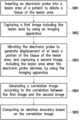
- the electronic device 160When the difference between the first length and the second length is less than a threshold value, the electronic device 160 generates an ablation boundary confirmation message.
- the difference between the first length and the second lengthis larger than or equal to the threshold value, the first ablation boundary and/or the second ablation boundary are recomputed.
- the reason for the large difference between the first length and the second lengthmay be caused by problems in the manual point scatting on the first correlation image 710 and/or the second correlation image 720 .
- the electronic device 160may prompt the doctor to manually scatter points again on the first correlation image 710 and/or the second correlation image 720 and re-obtain the first converged ablation boundary 711 and/or the converged second ablation boundary 721 , and then to determine whether or not an ablation range is correct according to the recomputed first ablation boundary 711 and the recomputed second ablation boundary 721 .
- FIG. 8is a flowchart of a tissue imaging method according to an exemplary embodiment.
- Step S 801inserting the electronic probe into the lesion area of the patient to ablate the tissue of the lesion area.
- Step S 802capturing the first image including the lesion area by using the imaging apparatus.
- Step S 803vibrating the electronic probe to generate displacement of at least a portion of the tissue in the lesion area, and capturing the second image, including the lesion area when the electronic probe vibrates, by using the imaging apparatus.
- Step S 804generating the correlation image according to the correlation between the first image and the second image.
- Step S 805computing the ablation boundary according to the correlation image.
- An embodiment of step S 805may further include: receiving multiple input data corresponding to multiple positions in the correlation image, and converging the positions to the ablation boundary by a boundary detection algorithm.
- an electronic probeis inserted into the lesion area of the patient to ablate the tissue of the lesion area, and the first image including the lesion area, and the second image, including the lesion area when the electronic probe vibrates, are captured by using the imaging apparatus.
- the ablation boundary according to the correlation imagemay be computed to confirm whether or not the lesion area is completely ablated.
Landscapes
- Health & Medical Sciences (AREA)
- Surgery (AREA)
- Life Sciences & Earth Sciences (AREA)
- Engineering & Computer Science (AREA)
- Veterinary Medicine (AREA)
- Molecular Biology (AREA)
- Nuclear Medicine, Radiotherapy & Molecular Imaging (AREA)
- Public Health (AREA)
- Biomedical Technology (AREA)
- Heart & Thoracic Surgery (AREA)
- Medical Informatics (AREA)
- General Health & Medical Sciences (AREA)
- Animal Behavior & Ethology (AREA)
- Otolaryngology (AREA)
- Plasma & Fusion (AREA)
- Physics & Mathematics (AREA)
- Cardiology (AREA)
- Oral & Maxillofacial Surgery (AREA)
- Pathology (AREA)
- Surgical Instruments (AREA)
Abstract
Description
Claims (8)
Priority Applications (1)
| Application Number | Priority Date | Filing Date | Title |
|---|---|---|---|
| US17/089,726US12329444B2 (en) | 2019-11-05 | 2020-11-05 | Tissue imaging method |
Applications Claiming Priority (4)
| Application Number | Priority Date | Filing Date | Title |
|---|---|---|---|
| US201962930583P | 2019-11-05 | 2019-11-05 | |
| TW109131879 | 2020-09-16 | ||
| TW109131879ATWI761954B (en) | 2019-11-05 | 2020-09-16 | Tissue imaging method |
| US17/089,726US12329444B2 (en) | 2019-11-05 | 2020-11-05 | Tissue imaging method |
Publications (2)
| Publication Number | Publication Date |
|---|---|
| US20210128234A1 US20210128234A1 (en) | 2021-05-06 |
| US12329444B2true US12329444B2 (en) | 2025-06-17 |
Family
ID=75686768
Family Applications (1)
| Application Number | Title | Priority Date | Filing Date |
|---|---|---|---|
| US17/089,726Active2042-07-27US12329444B2 (en) | 2019-11-05 | 2020-11-05 | Tissue imaging method |
Country Status (1)
| Country | Link |
|---|---|
| US (1) | US12329444B2 (en) |
Citations (23)
| Publication number | Priority date | Publication date | Assignee | Title |
|---|---|---|---|---|
| US20030171672A1 (en)* | 2002-03-08 | 2003-09-11 | Tomy Varghese | Elastographic imaging of in vivo soft tissue |
| US20080287780A1 (en)* | 2007-05-16 | 2008-11-20 | James Geoffrey Chase | Integral based parameter identification applied to three dimensional tissue stiffness reconstruction in a digital image-based elasto-tomography system |
| US7601122B2 (en) | 2003-04-22 | 2009-10-13 | Wisconsin Alumni Research Foundation | Ultrasonic elastography with angular compounding |
| CN101779966A (en) | 2010-02-25 | 2010-07-21 | 上海三埃弗电子有限公司 | Method for recognizing ultrasonic spectrum enveloped peaks by combining cardiac sound |
| US20100256530A1 (en)* | 2009-04-01 | 2010-10-07 | Tomy Varghese | Method and apparatus for monitoring tissue ablation |
| US20100268225A1 (en) | 2009-04-15 | 2010-10-21 | Tyco Healthcare Group Lp | Methods for Image Analysis and Visualization of Medical Image Data Suitable for Use in Assessing Tissue Ablation and Systems and Methods for Controlling Tissue Ablation Using Same |
| US8545407B2 (en)* | 2007-05-16 | 2013-10-01 | Super Sonic Imagine | Method and device for measuring a mean value of visco-elasticity of a region of interest |
| US8556888B2 (en) | 2006-08-04 | 2013-10-15 | INTIO, Inc. | Methods and apparatuses for performing and monitoring thermal ablation |
| US20140046316A1 (en)* | 2012-08-07 | 2014-02-13 | Covidien Lp | Microwave ablation catheter and method of utilizing the same |
| US20140112566A1 (en) | 2007-03-08 | 2014-04-24 | Sync-Rx, Ltd. | Automatic angiogram detection |
| TWI463964B (en) | 2012-03-03 | 2014-12-11 | Univ China Medical | System and apparatus for an image guided navigation system in surgery |
| TWI498099B (en) | 2013-05-27 | 2015-09-01 | Nat Cheng Kung University Hospital | Method and device for judging disease according to blood flow sound and evaluating effect of disease treatment |
| US20150327837A1 (en) | 2010-11-08 | 2015-11-19 | Vasonova, Inc. | Endovascular navigation system and method |
| WO2016115031A2 (en) | 2015-01-12 | 2016-07-21 | Sharma Virender K | Method and apparatus for tissue ablation |
| US9715885B2 (en) | 2013-03-05 | 2017-07-25 | Nec Corporation | Signal processing apparatus, signal processing method, and signal processing program |
| US20170319159A1 (en)* | 2014-12-11 | 2017-11-09 | Hefei Meyer Optoelectronic Technology Inc. | Method and apparatus for generating dental panoramic image, and panoramic camera for photographing teeth |
| US20180008237A1 (en)* | 2015-10-08 | 2018-01-11 | Zmk Medical Technologies Inc. | System for 3d multi-parametric ultrasound imaging |
| US9913624B2 (en) | 2013-02-28 | 2018-03-13 | Wisconsin Alumni Research Foundation | Method and apparatus for rapid acquisition of elasticity data in three dimensions |
| US20180168537A1 (en) | 2016-12-21 | 2018-06-21 | Industrial Technology Research Institute | Needle guide system and medical intervention system |
| US10241028B2 (en) | 2011-08-25 | 2019-03-26 | The General Hospital Corporation | Methods, systems, arrangements and computer-accessible medium for providing micro-optical coherence tomography procedures |
| US20190142528A1 (en) | 2016-05-23 | 2019-05-16 | Lx Medical Corporation | Method and system for image-guided procedures |
| CN109859833A (en) | 2018-12-28 | 2019-06-07 | 北京理工大学 | Method and device for evaluating the therapeutic effect of ablation surgery |
| US10488247B2 (en)* | 2014-05-13 | 2019-11-26 | Wisconsin Alumni Research Foundation | Method and apparatus for rapid acquisition of elasticity data in three dimensions |
- 2020
- 2020-11-05USUS17/089,726patent/US12329444B2/enactiveActive
Patent Citations (25)
| Publication number | Priority date | Publication date | Assignee | Title |
|---|---|---|---|---|
| WO2003075771A1 (en) | 2002-03-08 | 2003-09-18 | Wisconsin Alumni Research Foundation | Elastographic imaging of soft tissue in vivo |
| US20030171672A1 (en)* | 2002-03-08 | 2003-09-11 | Tomy Varghese | Elastographic imaging of in vivo soft tissue |
| US7601122B2 (en) | 2003-04-22 | 2009-10-13 | Wisconsin Alumni Research Foundation | Ultrasonic elastography with angular compounding |
| US8556888B2 (en) | 2006-08-04 | 2013-10-15 | INTIO, Inc. | Methods and apparatuses for performing and monitoring thermal ablation |
| US20140112566A1 (en) | 2007-03-08 | 2014-04-24 | Sync-Rx, Ltd. | Automatic angiogram detection |
| US8545407B2 (en)* | 2007-05-16 | 2013-10-01 | Super Sonic Imagine | Method and device for measuring a mean value of visco-elasticity of a region of interest |
| US20080287780A1 (en)* | 2007-05-16 | 2008-11-20 | James Geoffrey Chase | Integral based parameter identification applied to three dimensional tissue stiffness reconstruction in a digital image-based elasto-tomography system |
| US20100256530A1 (en)* | 2009-04-01 | 2010-10-07 | Tomy Varghese | Method and apparatus for monitoring tissue ablation |
| US8328726B2 (en) | 2009-04-01 | 2012-12-11 | Tomy Varghese | Method and apparatus for monitoring tissue ablation |
| US20100268225A1 (en) | 2009-04-15 | 2010-10-21 | Tyco Healthcare Group Lp | Methods for Image Analysis and Visualization of Medical Image Data Suitable for Use in Assessing Tissue Ablation and Systems and Methods for Controlling Tissue Ablation Using Same |
| CN101779966A (en) | 2010-02-25 | 2010-07-21 | 上海三埃弗电子有限公司 | Method for recognizing ultrasonic spectrum enveloped peaks by combining cardiac sound |
| US20150327837A1 (en) | 2010-11-08 | 2015-11-19 | Vasonova, Inc. | Endovascular navigation system and method |
| US10241028B2 (en) | 2011-08-25 | 2019-03-26 | The General Hospital Corporation | Methods, systems, arrangements and computer-accessible medium for providing micro-optical coherence tomography procedures |
| TWI463964B (en) | 2012-03-03 | 2014-12-11 | Univ China Medical | System and apparatus for an image guided navigation system in surgery |
| US20140046316A1 (en)* | 2012-08-07 | 2014-02-13 | Covidien Lp | Microwave ablation catheter and method of utilizing the same |
| US9913624B2 (en) | 2013-02-28 | 2018-03-13 | Wisconsin Alumni Research Foundation | Method and apparatus for rapid acquisition of elasticity data in three dimensions |
| US9715885B2 (en) | 2013-03-05 | 2017-07-25 | Nec Corporation | Signal processing apparatus, signal processing method, and signal processing program |
| TWI498099B (en) | 2013-05-27 | 2015-09-01 | Nat Cheng Kung University Hospital | Method and device for judging disease according to blood flow sound and evaluating effect of disease treatment |
| US10488247B2 (en)* | 2014-05-13 | 2019-11-26 | Wisconsin Alumni Research Foundation | Method and apparatus for rapid acquisition of elasticity data in three dimensions |
| US20170319159A1 (en)* | 2014-12-11 | 2017-11-09 | Hefei Meyer Optoelectronic Technology Inc. | Method and apparatus for generating dental panoramic image, and panoramic camera for photographing teeth |
| WO2016115031A2 (en) | 2015-01-12 | 2016-07-21 | Sharma Virender K | Method and apparatus for tissue ablation |
| US20180008237A1 (en)* | 2015-10-08 | 2018-01-11 | Zmk Medical Technologies Inc. | System for 3d multi-parametric ultrasound imaging |
| US20190142528A1 (en) | 2016-05-23 | 2019-05-16 | Lx Medical Corporation | Method and system for image-guided procedures |
| US20180168537A1 (en) | 2016-12-21 | 2018-06-21 | Industrial Technology Research Institute | Needle guide system and medical intervention system |
| CN109859833A (en) | 2018-12-28 | 2019-06-07 | 北京理工大学 | Method and device for evaluating the therapeutic effect of ablation surgery |
Non-Patent Citations (4)
| Title |
|---|
| "Office Action of Taiwan Counterpart Application", issued on Apr. 20, 2021, p. 1-p. 3. |
| Jingjing Xia et al., "Considering Angle Selection When Using Ultrasound Electrode Displacement Elastography to Evaluate Radiofrequency Ablation of Tissues" BioMed Research International, May 2014, pp. 1-11. |
| Shyam Bharat et al., "Radio-frequency ablation electrode displacement elastography: A phantom study", Medical Physic, Jun. 2008, pp. 2432-2442. |
| T. Varghese et al., "Elastographic Imaging of Thermal Lesions in the Liver in Vivo Following Radiofrequency Ablation: Preliminary Results", Ultrasound in Medicine & Biology, Jan. 2002, pp. 1467-1473. |
Also Published As
| Publication number | Publication date |
|---|---|
| US20210128234A1 (en) | 2021-05-06 |
Similar Documents
| Publication | Publication Date | Title |
|---|---|---|
| CN114096199B (en) | Representation of a target during aiming of an ultrasound probe | |
| CN112807025A (en) | Ultrasonic scanning guiding method, device, system, computer equipment and storage medium | |
| CN104994792B (en) | Ultrasonic diagnostic device and medical image processing device | |
| CN118717223A (en) | Systems and methods for placing medical devices in bones | |
| CN115210761A (en) | Multi-modality medical image registration and associated devices, systems, and methods | |
| US20200305837A1 (en) | System and method for guided ultrasound imaging | |
| CN101797167A (en) | Ultrasonic diagnostic device and ultrasonic diagnostic method | |
| US11461894B2 (en) | Information processing apparatus, inspection system, information processing method, and storage medium | |
| US20220044057A1 (en) | Device-to-image registration method, apparatus, and storage medium | |
| US10772601B2 (en) | Ultrasonic imaging apparatus and method for controlling the same | |
| CN112367920A (en) | Acoustic wave diagnostic apparatus and method for controlling acoustic wave diagnostic apparatus | |
| CN112367921A (en) | Acoustic wave diagnostic apparatus and method for controlling acoustic wave diagnostic apparatus | |
| US8663110B2 (en) | Providing an optimal ultrasound image for interventional treatment in a medical system | |
| KR20120102447A (en) | Method and apparatus for diagnostic | |
| JP7719261B2 (en) | ULTRASONIC SYSTEM AND METHOD FOR CONTROLLING ULTRASONIC SYSTEM - Patent application | |
| US12329444B2 (en) | Tissue imaging method | |
| JP5366429B2 (en) | Ultrasonic diagnostic apparatus and ultrasonic diagnostic apparatus control program | |
| CN108697410A (en) | Ultrasonic imaging device, image processing device and method thereof | |
| TWI761954B (en) | Tissue imaging method | |
| CN118845164A (en) | Portable puncture device based on ultrasound guidance | |
| JP2006246974A (en) | Ultrasonic diagnostic equipment with reference image display function | |
| JP2021023697A (en) | Ultrasonic diagnostic device and ultrasonic image processing method | |
| EP4309586A1 (en) | Ultrasonic diagnostic device and method for controlling ultrasonic diagnostic device | |
| US20050119570A1 (en) | Ultrasonic image and visualization aid | |
| TWI683286B (en) | Medical image alignment method |
Legal Events
| Date | Code | Title | Description |
|---|---|---|---|
| FEPP | Fee payment procedure | Free format text:ENTITY STATUS SET TO UNDISCOUNTED (ORIGINAL EVENT CODE: BIG.); ENTITY STATUS OF PATENT OWNER: LARGE ENTITY | |
| AS | Assignment | Owner name:INDUSTRIAL TECHNOLOGY RESEARCH INSTITUTE, TAIWAN Free format text:ASSIGNMENT OF ASSIGNORS INTEREST;ASSIGNORS:HSIEH, WAN-HSIN;WANG, YU-YAO;HSIAO, ZONG-YI;AND OTHERS;REEL/FRAME:054369/0492 Effective date:20201102 | |
| STPP | Information on status: patent application and granting procedure in general | Free format text:APPLICATION DISPATCHED FROM PREEXAM, NOT YET DOCKETED | |
| STPP | Information on status: patent application and granting procedure in general | Free format text:DOCKETED NEW CASE - READY FOR EXAMINATION | |
| STPP | Information on status: patent application and granting procedure in general | Free format text:NON FINAL ACTION MAILED | |
| STPP | Information on status: patent application and granting procedure in general | Free format text:RESPONSE TO NON-FINAL OFFICE ACTION ENTERED AND FORWARDED TO EXAMINER | |
| STPP | Information on status: patent application and granting procedure in general | Free format text:FINAL REJECTION MAILED | |
| STPP | Information on status: patent application and granting procedure in general | Free format text:RESPONSE AFTER FINAL ACTION FORWARDED TO EXAMINER | |
| STPP | Information on status: patent application and granting procedure in general | Free format text:ADVISORY ACTION MAILED | |
| STPP | Information on status: patent application and granting procedure in general | Free format text:DOCKETED NEW CASE - READY FOR EXAMINATION | |
| STPP | Information on status: patent application and granting procedure in general | Free format text:NON FINAL ACTION MAILED | |
| STPP | Information on status: patent application and granting procedure in general | Free format text:RESPONSE TO NON-FINAL OFFICE ACTION ENTERED AND FORWARDED TO EXAMINER | |
| STCF | Information on status: patent grant | Free format text:PATENTED CASE |