US12329327B2 - Sheet material dispenser assembly for selectively dispensing sheet material from a plurality of supplies of rolled sheet material - Google Patents
Sheet material dispenser assembly for selectively dispensing sheet material from a plurality of supplies of rolled sheet materialDownload PDFInfo
- Publication number
- US12329327B2 US12329327B2US18/107,260US202318107260AUS12329327B2US 12329327 B2US12329327 B2US 12329327B2US 202318107260 AUS202318107260 AUS 202318107260AUS 12329327 B2US12329327 B2US 12329327B2
- Authority
- US
- United States
- Prior art keywords
- sheet material
- drive
- gear
- roller
- driven roller
- Prior art date
- Legal status (The legal status is an assumption and is not a legal conclusion. Google has not performed a legal analysis and makes no representation as to the accuracy of the status listed.)
- Active, expires
Links
Images


Classifications
- A—HUMAN NECESSITIES
- A47—FURNITURE; DOMESTIC ARTICLES OR APPLIANCES; COFFEE MILLS; SPICE MILLS; SUCTION CLEANERS IN GENERAL
- A47K—SANITARY EQUIPMENT NOT OTHERWISE PROVIDED FOR; TOILET ACCESSORIES
- A47K10/00—Body-drying implements; Toilet paper; Holders therefor
- A47K10/24—Towel dispensers, e.g. for piled-up or folded textile towels; Toilet paper dispensers; Dispensers for piled-up or folded textile towels provided or not with devices for taking-up soiled towels as far as not mechanically driven
- A47K10/32—Dispensers for paper towels or toilet paper
- A47K10/34—Dispensers for paper towels or toilet paper dispensing from a web, e.g. with mechanical dispensing means
- A47K10/36—Dispensers for paper towels or toilet paper dispensing from a web, e.g. with mechanical dispensing means with mechanical dispensing, roll switching or cutting devices
- A47K10/3606—The cutting devices being motor driven
- A47K10/3612—The cutting devices being motor driven with drive and pinch rollers
- A—HUMAN NECESSITIES
- A47—FURNITURE; DOMESTIC ARTICLES OR APPLIANCES; COFFEE MILLS; SPICE MILLS; SUCTION CLEANERS IN GENERAL
- A47K—SANITARY EQUIPMENT NOT OTHERWISE PROVIDED FOR; TOILET ACCESSORIES
- A47K10/00—Body-drying implements; Toilet paper; Holders therefor
- A47K10/24—Towel dispensers, e.g. for piled-up or folded textile towels; Toilet paper dispensers; Dispensers for piled-up or folded textile towels provided or not with devices for taking-up soiled towels as far as not mechanically driven
- A47K10/32—Dispensers for paper towels or toilet paper
- A47K10/34—Dispensers for paper towels or toilet paper dispensing from a web, e.g. with mechanical dispensing means
- A47K10/36—Dispensers for paper towels or toilet paper dispensing from a web, e.g. with mechanical dispensing means with mechanical dispensing, roll switching or cutting devices
- A47K10/3606—The cutting devices being motor driven
- A47K10/3625—The cutting devices being motor driven with electronic control means
- A—HUMAN NECESSITIES
- A47—FURNITURE; DOMESTIC ARTICLES OR APPLIANCES; COFFEE MILLS; SPICE MILLS; SUCTION CLEANERS IN GENERAL
- A47K—SANITARY EQUIPMENT NOT OTHERWISE PROVIDED FOR; TOILET ACCESSORIES
- A47K10/00—Body-drying implements; Toilet paper; Holders therefor
- A47K10/24—Towel dispensers, e.g. for piled-up or folded textile towels; Toilet paper dispensers; Dispensers for piled-up or folded textile towels provided or not with devices for taking-up soiled towels as far as not mechanically driven
- A47K10/32—Dispensers for paper towels or toilet paper
- A47K10/34—Dispensers for paper towels or toilet paper dispensing from a web, e.g. with mechanical dispensing means
- A47K10/36—Dispensers for paper towels or toilet paper dispensing from a web, e.g. with mechanical dispensing means with mechanical dispensing, roll switching or cutting devices
- A47K10/3631—The cutting devices being driven manually
- A47K10/3637—The cutting devices being driven manually using a crank or handle
- A—HUMAN NECESSITIES
- A47—FURNITURE; DOMESTIC ARTICLES OR APPLIANCES; COFFEE MILLS; SPICE MILLS; SUCTION CLEANERS IN GENERAL
- A47K—SANITARY EQUIPMENT NOT OTHERWISE PROVIDED FOR; TOILET ACCESSORIES
- A47K10/00—Body-drying implements; Toilet paper; Holders therefor
- A47K10/24—Towel dispensers, e.g. for piled-up or folded textile towels; Toilet paper dispensers; Dispensers for piled-up or folded textile towels provided or not with devices for taking-up soiled towels as far as not mechanically driven
- A47K10/32—Dispensers for paper towels or toilet paper
- A47K10/34—Dispensers for paper towels or toilet paper dispensing from a web, e.g. with mechanical dispensing means
- A47K10/36—Dispensers for paper towels or toilet paper dispensing from a web, e.g. with mechanical dispensing means with mechanical dispensing, roll switching or cutting devices
- A47K10/3687—Dispensers for paper towels or toilet paper dispensing from a web, e.g. with mechanical dispensing means with mechanical dispensing, roll switching or cutting devices with one or more reserve rolls
- A—HUMAN NECESSITIES
- A47—FURNITURE; DOMESTIC ARTICLES OR APPLIANCES; COFFEE MILLS; SPICE MILLS; SUCTION CLEANERS IN GENERAL
- A47K—SANITARY EQUIPMENT NOT OTHERWISE PROVIDED FOR; TOILET ACCESSORIES
- A47K10/00—Body-drying implements; Toilet paper; Holders therefor
- A47K10/24—Towel dispensers, e.g. for piled-up or folded textile towels; Toilet paper dispensers; Dispensers for piled-up or folded textile towels provided or not with devices for taking-up soiled towels as far as not mechanically driven
- A47K10/32—Dispensers for paper towels or toilet paper
- A47K10/34—Dispensers for paper towels or toilet paper dispensing from a web, e.g. with mechanical dispensing means
- A47K10/38—Dispensers for paper towels or toilet paper dispensing from a web, e.g. with mechanical dispensing means the web being rolled up with or without tearing edge
- A—HUMAN NECESSITIES
- A47—FURNITURE; DOMESTIC ARTICLES OR APPLIANCES; COFFEE MILLS; SPICE MILLS; SUCTION CLEANERS IN GENERAL
- A47K—SANITARY EQUIPMENT NOT OTHERWISE PROVIDED FOR; TOILET ACCESSORIES
- A47K10/00—Body-drying implements; Toilet paper; Holders therefor
- A47K10/24—Towel dispensers, e.g. for piled-up or folded textile towels; Toilet paper dispensers; Dispensers for piled-up or folded textile towels provided or not with devices for taking-up soiled towels as far as not mechanically driven
- A47K10/32—Dispensers for paper towels or toilet paper
- A47K10/34—Dispensers for paper towels or toilet paper dispensing from a web, e.g. with mechanical dispensing means
- A47K10/36—Dispensers for paper towels or toilet paper dispensing from a web, e.g. with mechanical dispensing means with mechanical dispensing, roll switching or cutting devices
- A47K2010/3668—Detection of the presence of a user
Definitions
- the present disclosureis directed to dispenser assemblies for rolled sheet materials, and more particularly, is directed to dispenser assemblies for selectively dispensing from a plurality of supplies of rolled sheet material. Other aspects are also described.
- Dispensers for sheet materialsare commonly used in hospitals, restrooms, and other facilities. Some dispensers have more than one supply of sheet material, e.g., multiple rolls of sheet material, for dispensing/feeding. When a supply of sheet material in such dispensers is running low or has been fully dispensed, a transfer of the feeding of sheet material to a new supply generally must be performed, which often must be done manually.
- the present disclosureaddresses these and other related and unrelated problems/issues in the relevant art.
- the present disclosureis directed to a dispenser assembly for dispensing sheet materials such as rolls of tissue, paper towels, and/or other rolled sheet material products.
- the dispenser assemblygenerally includes a dispenser housing having a plurality of supplies of rolled sheet material supported therein.
- Each supply of rolled sheet materialis supported by a corresponding support assembly within the dispenser housing.
- the plurality of supplies of sheet materialcan include a first supply of sheet material supported by a corresponding first support assembly, and a second supply of sheet material supported by a corresponding second support assembly.
- the first and second support assembliescan be spaced apart from each other along the dispenser housing.
- the dispenser assemblyfurther can include a dispensing system for controlling the dispensing of selected, predetermined amounts of sheet material from at least one of the plurality of supplies of sheet material.
- the dispensing systemcan include a plurality of driven roller assemblies for engaging and driving the sheet material from the supplies of rolled sheet material.
- Each driven roller assemblygenerally will be associated with at least one supply of the plurality of supplies of sheet material for dispensing sheet material therefrom.
- the first supply of rolled sheet materialcan be dispensed by a first driven roller assembly and the second supply of rolled sheet material can be dispensed by a second driven roller assembly.
- Each driven roller assemblycan have at least one driven roller driven by a drive mechanism (e.g., a motor or other suitable drive mechanism) in communication therewith.
- the drive mechanismcan be operatively connected to the driven roller(s) by a belt or series of belts (e.g., one or more belts engaging a belt pulley or belt gear connected to each of the driven rollers).
- the dispensing assemblyfurther can include at least one guide roller that engages the sheet material and is rotatable with the rotation of the driven roller to help facilitate feeding and dispensing of the sheet material.
- the dispenser assemblyfurther can include additional guide or pressing rollers positioned adjacent each of the driven rollers to help guide the sheet material during dispensing thereof without departing from the scope of the present disclosure.
- Each of the driven rollerscan be configured to rotate in a desired or selected direction, and typically can be rotated by the drive mechanism for a selected number of rotations as needed to dispense the selected amounts of sheet material from their corresponding supply of rolled sheet material, but generally will remain stationary when the drive mechanism is reversed or driven in the opposite direction.
- each driven rollercan include or can be coupled to a clutch mechanism (e.g., a hybrid or one-way clutch mechanism) or other disengageable drive connection that engages the driven roller and causes it to rotate when driven/rotated in one direction and disengages the driven roller and allows it to stay substantially stationary when driven in the opposite direction.
- a clutch mechanisme.g., a hybrid or one-way clutch mechanism
- the first driven rollercan be rotated when the drive mechanism is driven in a first direction to dispense sheet material from the first supply of rolled sheet material, while the second driven roller can remain generally stationary such that sheet material is not dispensed from the second supply of rolled sheet material.
- the second driven rollercan be rotated to dispense selected predetermined amounts of sheet material from the second supply of rolled sheet material, while the first driven roller can be disengaged and remain generally stationary such that sheet material is not dispensed therefrom.
- the dispenser assembly of the present disclosureprovides for selective dispensing of sheet material from the plurality of supplies of sheet material as needed.
- the dispensercan switch the dispensing of sheet material from the one supply of sheet material to the other.
- This change or switch/transfer of feeding from one supply to anothercan be substantially automatic, i.e., in response to a signal from a sensor or monitoring system, by a command from a control system for the dispenser, manually by a switch upon receipt of one or more signals from a device external to the dispenser assembly, etc.
- the drive assemblyadditionally can include a tensioning assembly including one or more biasing members for providing a substantially constant tension along the drive belt.
- the one or more biasing memberse.g., including one or more tension springs
- the motore.g., one end of the one or more springs can be connected to the motor or a support therefor, and another end of the one or more springs can be connected to the dispenser housing or a component attached thereto).
- the tensioning assemblycan include a bracket movably supporting the drive mechanism along the dispenser housing, and the one or more biasing members can be coupled to the bracket to bias the tensioning assembly sufficient to apply tension along the drive belt and/or for providing dampening of vibrations from an operation of the dispenser assembly.
- the dispenser assemblycan include at least one cutting mechanism (e.g., including a tear bar(s), serrated cutting blade(s), knife(s), or other sharpened portion(s)) positioned along the discharge of the dispenser housing for severance of dispensed sheet material from the supplies of sheet material.
- at least one cutting mechanisme.g., including a tear bar(s), serrated cutting blade(s), knife(s), or other sharpened portion(s)
- the dispenser assemblycan include pawl member assembly including a pivotally mounted pawl member located proximate or otherwise along the cutting mechanism such that movement of the sheet material into the cutting mechanism for severance thereof moves the pawl member from a first position to a second position.
- the pawl member assemblyfurther can generate one or more signals that can be sent to a control circuit of the dispenser to notify the control circuit that a portion of the dispensed sheet material has been removed.
- the dispensing assemblyalso can include a sheet material detection sensor including an emitter and a detector focused across at least a portion of the discharge path(s) extending through the discharge.
- the sheet material detection sensorcan be activated by a control system of the dispenser assembly to verify that the sheet material has been removed from the discharge.
- the dispensing assemblyfurther can include a monitoring system configured to determine a supply level of the supplies of sheet material, and upon a determination that the supply level of the supplies of sheet material is below a threshold level, the direction of the drive mechanism can be changed.
- a monitoring systemconfigured to determine a supply level of the supplies of sheet material, and upon a determination that the supply level of the supplies of sheet material is below a threshold level, the direction of the drive mechanism can be changed.
- FIG. 1provides a schematic illustration of a dispensing assembly for selectively dispensing a predetermined amount of sheet material from a plurality of supplies of sheet material according to principles of the present disclosure.
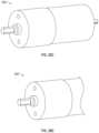
- FIG. 2 Ashows a perspective view of a drive system for the dispensing assembly of FIG. 1 .
- FIG. 2 Bshows a belt pulley of a driven roller of the drive system of FIG. 2 A with an integrated clutch mechanism according to principles of the of the present disclosure.
- FIG. 2 Cillustrates a drive system according to further principles of the present disclosure.
- FIGS. 3 A- 3 Billustrate examples of a cutting mechanism and pawl member according to example constructions of the present disclosure.
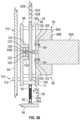
- FIGS. 4 A- 4 Bshow perspective and cross-sectional views of a tensioning assembly according to principles of the present disclosure.
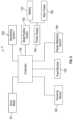
- FIG. 5shows a block diagram of an example of a control system of the dispenser assembly according to principles of the present disclosure.
- FIGS. 6 - 8are views of a dispenser assembly according to additional embodiments of the disclosure.
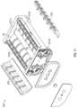
- FIGS. 9 - 13are views of a dispensing system of the dispenser assembly of FIGS. 6 - 8 .
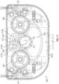
- FIGS. 14 - 18are views of a transmission assembly of the dispensing system of FIGS. 9 - 13 .
- FIGS. 19 A- 19 Eshow additional views of the features of FIGS. 6 - 18 .
- FIGS. 20 A- 22are views of a dispensing system according to additional embodiments of the disclosure.
- FIGS. 23 - 27 Bare views of a transmission assembly of the dispensing system of FIGS. 20 A- 22 .
- FIGS. 28 A and 28 Bshow views of other embodiments of a dispensing system.
- FIGS. 28 C and 28 Dshow views of other embodiments of a drive mechanism for a dispensing system.
- Rangescan be expressed herein as from “about” one particular value, and/or to “about” another particular value. When such a range is expressed, another aspect includes from the one particular value and/or to the other particular value. Similarly, when values are expressed as approximations, by use of the antecedent “about,” it will be understood that the particular value forms another aspect. It will be further understood that the endpoints of each of the ranges are significant both in relation to the other endpoint, and independently of the other endpoint.
- the terms “optional” or “optionally”mean that the subsequently described event or circumstance can or cannot occur, and that the description includes instances where said event or circumstance occurs and instances where it does not.
- conditional languagesuch as, among others, “can,” “could,” “might,” or “can,” unless specifically stated otherwise, or otherwise understood within the context as used, is generally intended to convey that certain aspects include, while other aspects do not include, certain features, elements and/or steps. Thus, such conditional language is not generally intended to imply that features, elements and/or steps are in any way required for one or more particular aspects or that one or more particular aspects necessarily include logic for deciding, with or without user input or prompting, whether these features, elements and/or steps are included or are to be performed in any particular embodiment.
- the term “plurality”refers to two or more items or components.
- the terms “comprising,” “including,” “carrying,” “having,” “containing,” and “involving,” whether in the written description or the claims and the like,are open-ended terms, i.e., to mean “including but not limited to.” Thus, the use of such terms is meant to encompass the items listed thereafter, and equivalents thereof, as well as additional items. Only the transitional phrases “consisting of” and “consisting essentially of,” are closed or semi-closed transitional phrases, respectively, with respect to any claims.
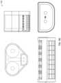
- FIG. 1shows a dispenser assembly 10 for dispensing a rolled sheet material 11 , such as tissue rolls, paper towel rolls, or other suitable rolled sheet material products.
- the dispenser assembly 10can include a dispenser housing 12 having a cover 12 A that is movable/removable to allow access to the components of the dispenser assembly 10 , and a backing portion 12 B that is configured to mount or otherwise connect (e.g., via fasteners, adhesive, etc.) to the dispenser assembly 10 to a wall, partition, or other suitable support within a facility, such as, for example, a restroom, hospital room, and the like.
- the dispenser housing 12can be formed from plastic materials, metallic materials, other suitable synthetic or composite materials, or combinations thereof.
- the dispenser housing 12further includes one or more chambers or compartments 13 defined therein and sized, dimensioned, and/or configured to receive and house a plurality of supplies 14 of sheet material 11 therein.
- the dispenser housing 12also including a discharge 15 , e.g., including one or more defined apertures or openings, that facilitates dispensing of the sheet material 11 of the supplies of sheet material 14 from the dispenser assembly 10 .
- each supply 14 of sheet materialtypically includes a roll or spindle 14 A with sheet material 11 wrapped or spun thereabout.
- the dispenser assembly 10further includes a plurality of support assemblies 16 rotatable supporting plurality of supplies 14 within the dispenser housing 12 . That is, each supply of sheet material 14 is configured to be supported by a corresponding support assembly 16 positioned with the chamber(s) 13 of the dispenser housing 12 .
- the plurality of supplies 14 of sheet materialcan include a first supply 18 of sheet material that is supported by a corresponding first support assembly 20 , and a second supply 22 of sheet material that is supported by a second support assembly 24 .
- the first and second support assemblies 20 / 24can be spaced apart from each other along the dispenser housing 12 as generally indicated in FIG. 1 .
- a partition or other suitable portion 25further can be positioned between the first and second support assemblies 20 / 24 .
- the support assemblies 20 / 24can include slots or grooves 30 / 32 defined in or along the dispenser housing 12 (e.g., in the cover 12 A and/or backing portion 12 B or other walls, portions, supports, etc. within the dispenser housing 12 ).
- the slots 30 / 32can be configured to at least partially receive first and second ends 34 / 36 of the support roll or spindle 38 / 40 for the first and second supplies 18 / 22 of sheet material, and at least a portion of each of the supplies of sheet material being supported by and/or resting on or engaging a corresponding guide roller 42 / 44 .
- the slots or grooves of the roll support assemblies 20 / 24can include one or more angled or sloped portions 46 / 48 having a variable slope or angle to increase and/or decrease an amount of force the supply 18 / 22 of rolled sheet material exerts on the guide rollers 42 / 44 .
- the slope of portions 46 / 48can be selected such that as the sheet material is fed from the supplies 18 / 22 of sheet material and is depleted (e.g., the amount and thus the weight of sheet material remaining on a roll 38 / 40 decreases), the position of the supply rolls 18 / 22 will change so as to generally maintain a substantially constant downward force exerted by the sheet material supplies 18 / 22 on the respective guide rollers 42 / 44 .
- the guide rollers 42 / 44 of the dispenser assembly 10will be positioned along or substantially proximate, adjacent, etc. and engaging the supplies 14 of sheet material, with the first guide roller 42 engaging the first supply 18 of sheet material and the second guide roller 44 engaging the second supply 22 of sheet material.
- Each of the guide rollers 42 / 44can include an elongated body 43 / 45 defining a substantially cylindrical sidewall 43 A/ 45 A configured to engage the sheet material from the supplies 18 / 22 of sheet material, e.g., to at least partially support the supplies 18 / 22 of sheet material within the slots 30 / 32 ( FIG. 1 ) and to facilitate dispensing of the supplies 18 / 22 of sheet material from the dispenser assembly 10 .
- the body 43 / 45 of the guide rollers 42 / 44can be formed from a plastic material, though other materials, such as wood, elastomeric materials, such as rubber, or other composite or synthetic materials or combinations thereof, can be used without departing from the scope of the present disclosure.
- the guide rollers 42 / 44also can include bands 43 B/ 45 B of a gripping material, e.g., including a rubber or other elastomers or synthetic materials, to assist in gripping or engaging the sheet material 11 without causing damage thereto.
- the guide rollers 42 / 44are rotatably mounted within the dispenser housing 12 . FIG.
- the guide rollers 42 / 44can include bearing assemblies 47 / 49 attached to the guide rollers 42 / 44 that support the guide rollers 42 / 44 within the dispenser housing 12 , such that the guide rollers 42 / 44 are rotatable thereabout (e.g., the bearing assemblies 47 / 49 can be fixedly connected to the backing portion 14 B and/or the cover 14 A or other walls, portions, supports, etc. of the dispenser assembly 12 ).
- the bearing assemblies 47 / 49can include, for example and without limitation, roller bearings, ball bearings, and the like, or other suitable mechanisms that facilitate rotation of the guide rollers 42 / 44 .
- FIGS. 1 and 2 Afurther show that the dispenser assembly 10 includes a dispensing system or mechanism 50 for selectively dispensing predetermined amounts (i.e., particular, selected lengths) of sheet material 11 from the plurality of supplies 18 / 22 of sheet material.
- the dispensing system 50can include a plurality of driven rollers 56 / 58 for engaging and driving the sheet material from the supplies 18 / 22 of sheet material.
- the first supply 18 of sheet materialcan be dispensed by a corresponding first driven roller 56 and the second supply 22 of rolled sheet material can be dispensed by a corresponding second driven roller 58 .
- the first driven roller 56will engage and draw or urge sheet material from the first supply 18 of sheet material along a first discharge path 65 A toward and out of the discharge 15 of the dispenser housing 12
- the second driven roller 58will engage and draw or urge sheet material from the second supply 22 of sheet material along a second discharge path 65 B toward and out of the discharge of the dispenser housing 12 .
- the dispenser assembly 10includes a drive mechanism 60 operatively connected or coupled to the plurality of driven rollers 56 / 58 to drive rotation thereof.
- the drive mechanism 60can include a motor 60 A (e.g., a brushless servo or stepper motor, or other, similar type of variable speed, reversible electric motor), though or other suitable drive mechanisms, drive systems, actuators, and/or the like can be used without departing from the scope of the present disclosure.
- the driven rollers 56 / 58 positioned substantially adjacent and along the guide rollers 42 / 44rotate under the power of the drive mechanism 60 to pull the sheet material 11 from the respective supplies 18 / 22 and along the discharge paths 65 A/B at least partially defined between the driven rollers 56 / 58 and associated guide rollers 42 / 44 and through the discharge 15 defined in the dispenser housing 12 .
- Each driven roller 56 / 58further is selectively driven/rotated by a drive mechanism 60 linked to or otherwise in communication with the driven rollers 56 / 58 .
- the drive mechanism 60communicates with a control circuitry 5 (e.g., including controller 100 as shown in FIG.
- the drive mechanism 60can be driven in a first direction, e.g., D 1 in FIG. 1 , to drive the first driven roller 56 and move the sheet material from the corresponding first supply 18 of sheet material along the first discharge path 65 A toward and out from the discharge 15 of the dispenser housing 12 .
- the drive mechanism 60also can be reversed and driven in a second direction, e.g., D 2 in FIG. 1 , to drive the second driven roller 58 and move the sheet material from the corresponding second supply 22 of sheet material along the second discharge path 65 B toward and out from the discharge 15 of the dispenser housing 12 .
- FIG. 2 Ashows that the driven rollers 56 / 58 can include an elongated body 57 / 59 with a generally cylindrical sidewall 57 A/ 59 A that is configured to engage and pull the sheet material 11 from the respective supplies of sheet material 18 / 22 .
- the driven rollers 56 / 58are rotatably mounted within the dispenser housing 12 by one or more bearing assemblies 61 / 63 (e.g., including roller bearings, ball bearings, etc. or other suitable bearing mechanisms that facilitate rotation of the driven rollers 56 / 58 ) connected to the backing portion 12 B and/or the cover 12 A or other suitable wall, portion, support, etc. within the dispenser housing 12 .
- bearing assemblies 61 / 63e.g., including roller bearings, ball bearings, etc. or other suitable bearing mechanisms that facilitate rotation of the driven rollers 56 / 58
- the driven rollers 56 / 58further can include bands of a gripping material 57 B/ 59 B, such as a rubber or synthetic material, to assist in pulling the sheet material between the driven rollers 56 / 58 and guide rollers 42 / 44 , without causing damage to the sheet material as it passes between the driven 56 / 58 and guide rollers 42 / 44 .
- a gripping material 57 B/ 59 Bsuch as a rubber or synthetic material
- the driven rollers 56 / 58 and/or the guide roller 42 / 44can be biased into engagement with each other (e.g., by one or more biasing mechanism, such as springs, e.g., compression springs, tension springs, torsion springs, and the like; elastic cylinders; and/or other suitable biasing mechanisms) to press or otherwise engage the sheet material between the driven rollers 56 / 58 and guide rollers 42 / 44 .
- the roller assemblies 52 / 54further can include additional guide or pressing rollers positioned adjacent the driven rollers 56 / 58 and/or guide rollers 42 / 44 to guide and/or engage the sheet material without departing from the scope of the present disclosure.
- the drive system 50can include a belt driven transmission assembly 62 including a driven belt 62 A operatively connecting or engaging the driven mechanism 60 and driven rollers 56 / 58 to transfer power therebetween for selectively driving rotation of the first driven roller 42 and/or the second driven roller 44 .
- the drive mechanism 60can be operatively connected to each of the driven rollers 56 / 58 by a drive belt 62 A that engages corresponding belt pulleys or belt gears 67 / 69 connected to each of the driven rollers 56 / 58 and a belt pulley or belt gear 71 connected to the driven mechanism 60 .
- the belt gears 67is operatively connected to each of the driven rollers 56 / 58 by a drive belt 62 A that engages corresponding belt pulleys or belt gears 67 / 69 connected to each of the driven rollers 56 / 58 and a belt pulley or belt gear 71 connected to the driven mechanism 60 .
- the belt gears 67.
- 69 , and 71can include a first driven roller belt gear 67 operatively connected to the first driven roller 42 ; a second driven roller belt gear 69 operatively connected to the second driven roller 44 ; and a drive mechanism belt gear 71 operatively connected to the drive mechanism 60 .
- a single belt 62is shown operatively connected to the drive mechanism 60 (e.g., engaging the belt gear 71 that is coupled to a driveshaft 60 B of the motor 60 A) and to each of the driven rollers 56 / 58 (e.g., engaging the belt gears 67 / 69 attached thereto or otherwise in operative communication therewith); however, it is contemplated that a series of belts can be used to connect the drive mechanism 60 and driven roller 56 / 58 , such as one drive belt connecting the drive mechanism 60 and driven roller 56 and another drive belt connecting the drive mechanism 60 and driven roller 58 , without departing from the scope of the present disclosure. It further will be understood that in additional or alternative constructions, one or more of the driven rollers 56 / 58 can be connected to the driven mechanism 60 by other suitable transmission assemblies or mechanisms, such as a series of gears or other suitable transmission assemblies.
- the belt gears 67 / 69can be operatively connected to the rollers 42 / 44 (rather than rollers 56 / 59 ) such that the rollers 42 / 44 are driven rollers. That is, as FIG. 2 C indicates, the belt 62 A can engage the belt gears 67 / 69 attached to the ends of the driven rollers 42 / 44 such that the driven rollers 42 / 44 can be selectively driven and rotated by the drive mechanism 60 .
- the rollers 56 / 58which are not directly engaged by the belt 62 A, are allowed to float, and further can be biased into engagement with the driven rolls 42 / 44 (e.g., by one or more biasing assemblies including at least one biasing member, such as a spring, biased cylinder, etc.).
- the rollers 56 / 58accordingly can be configured as guide or pressing rollers to help to direct the sheet material along the respective discharge paths 65 A and 65 B.
- at least one or a plurality of pressing or guide rollerscan be positioned along and biased into engagement with the driven rollers 42 / 44 .
- the pressing or guide roller(s)can be coupled to the rollers 42 / 44 by a transmission mechanism, such as a belt driven transmission mechanism, that can transfer power between the rollers 42 / 44 and 56 / 58 and also can be configured to bias the rollers 42 / 44 and 56 / 58 towards engagement with one another.
- a transmission mechanismsuch as a belt driven transmission mechanism
- the belt 62 Aalso can include a plurality of cogs or teeth 62 B disposed thereabout and configured to engage corresponding notches, teeth, and the like in the belt gears, i.e., 67 , 69 , and/or 71 .
- the belt 62 A and/or the cogs 62 B thereofcan be formed from a rubber material, such as a chloroprene rubber, or other suitable rubber, though any suitable material can be used without departing from the scope of the present disclosure.
- the belt 62 Aalso can include one or more layers or plies, including a tensile layer that comprises a reinforcement, for example, fiberglass, though the belt can comprise any suitable material, e.g., other rubbers, plastics, synthetics and/or composites, without departing from the present disclosure. Additionally, the belt 62 A can include a wrapping, such as a cloth or sheet material comprising high elastic nylon, though the wrap cloth can comprise any other suitable material without departing from the present disclosure.
- the driven rollers 56 / 58(or driven rollers 42 / 44 as shown in FIG. 2 C ) generally are configured to be selectively rotatable to dispense amounts of sheet material 11 from their corresponding supply of sheet material 18 or 22 when driven in one direction by the drive mechanism 60 , but generally will remain substantially stationary, such that sheet material 11 is not dispensed from its corresponding supply of sheet material 18 or 22 , when the drive mechanism 60 is driven in the opposite direction.
- first driven roller 56is rotated by the drive mechanism 60 in a first direction D 1 shown in FIG.
- the first driven roller 56can engage and feed/dispense sheet material from the first supply 18 of sheet material, while the second driven roller 58 remains generally stationary such that sheet material from the second supply 22 is not dispensed therefrom.
- the second drive roller 58will be rotated to dispense the select/predetermined amounts of sheet material from the second supply 22 of sheet material while the first driven roller 56 remains generally stationary, such that the sheet material is not dispensed from the first supply 18 of rolled sheet material.
- the dispenser assembly 10can provide for selective dispensing of the plurality of supplies 18 or 22 of sheet material by controlling the driving direction of the drive mechanism 60 .
- sheet material 11can be dispensed from one supply of sheet material 18 or 22 , until such supply is substantially dispensed or exhausted, after which the direction of the drive mechanism 60 can be switched/changed (e.g., reversed or otherwise altered) to transfer to and begin dispensing the sheet material 11 from the other supply of sheet material 18 or 22 .
- the driven rollers 56 / 58also can include or incorporate a clutch assembly or mechanism 70 , such as a hybrid or one-way clutch mechanism, that allows for selective transfer of power between the drive mechanism 60 and the driven rollers 56 / 58 (or driven rollers 42 / 44 as shown in FIG. 2 C ), such as generally shown in FIGS. 2 A and 2 B .
- a clutch assembly or mechanism 70such as a hybrid or one-way clutch mechanism, that allows for selective transfer of power between the drive mechanism 60 and the driven rollers 56 / 58 (or driven rollers 42 / 44 as shown in FIG. 2 C ), such as generally shown in FIGS. 2 A and 2 B .
- the clutch assembly 70can be incorporated or integrated with the belt gears 67 / 69 connected to the driven rollers 56 / 58 (or rollers 42 / 44 as shown in FIG. 2 C ).
- the clutch assembly 70 of the first driven roller 56will lock/engage for transfer of power/torque to the first driven roller 56 so that the first driven roller 56 is driven by the drive mechanism 60 and rotated to dispense its corresponding supply 18 of sheet material (while the clutch assembly 70 of the second driven roller 58 remains generally disengaged such that the second driven roller 58 is substantially stationary as no power/torque is transferred from the drive mechanism 60 and the second driven roller 58 ).
- the clutch assembly 70 for the first driven roller 56will unlock or disengage such that there is no transfer of power/torque between the drive mechanism 60 and the first driven roller 56 such that the first driven roller 56 remains generally stationary (while the clutch assembly 70 for the second driven roller 58 engages or locks for transfer of power/torque to the second driven roller 58 so that the second driven roller 58 is rotated to dispense its corresponding supply 22 of sheet material).
- each clutch assembly 70can include one or more tracks/races, such as inner and outer races 72 / 74 , that rotate together (when engaged) or independently of one another (when disengaged).
- the clutch assembly 70further can include a plurality of biased rollers or bearings 76 can be received between the inner and outer races and can be biased such as by a series of springs 78 or other biasing mechanisms, toward/against corresponding surfaces or other engagement portions 79 of the outer race 74 to stop or prevent rotation of the bearings 76 and provide engagement or coupling between the inner 72 and outer 74 races.
- a series of springs 78 or other biasing mechanismstoward/against corresponding surfaces or other engagement portions 79 of the outer race 74 to stop or prevent rotation of the bearings 76 and provide engagement or coupling between the inner 72 and outer 74 races.
- the rollers 76move away from and do not engage the outer race 74 (e.g., do not engage the engagement portions 79 ) under the control of the springs 78 , such that the rollers 76 can rotate or spin freely allowing the inner race 72 to turn independently of the outer race 74 , such that the driven roller 58 does not rotate and remains generally stationary.
- the dispenser assembly 10further can include a tensioning assembly 80 including one or more biasing members 82 .
- the one or more biasing members 82can be operatively connected to the drive mechanism 60 for biasing the drive mechanism 60 , such as to provide tension along the drive belt 62 A (e.g., to substantially prevent, reduce, or inhibit wear, slippage, etc. thereof) and/or to provide dampening for the drive mechanism 60 (e.g., dampening or absorbing motor vibrations or other components of the drive system).
- the biasing member(s) 82can include a tension spring(s) 82 A with one end 83 thereof operatively connected to the drive mechanism 60 (or part/component connected to the drive mechanism 60 or a bracket, support, frame, etc. supporting the drive mechanism within the dispenser housing 12 ) and another end thereof 85 operatively connected to a portion of the dispenser housing 12 .
- FIGS. 3 A and 3 Billustrate perspective and cross-sectional views of a tensioning assembly 80 according to one example construction of the present disclosure.
- the tensioning assembly 80can include a support assembly 90 including a bracket 92 that is connected to and supports the drive mechanism 60 (i.e., the motor 60 A and the belt gear 71 attached thereto) and that is movably connected to the dispenser housing 12 (e.g., movably connected to a wall, support, etc. 94 of, or otherwise connected to, the dispenser housing 12 ( FIG. 3 B ).
- the bracket 92further includes one or more connection mechanisms 93 that are configured to connect to the biasing member(s) 82 .
- one hooked, or looped end 83 of the biasing member(s) 82can be connected to the connection mechanism 93 (e.g., including a rod 93 A or other suitable connection mechanism, such as a hooked or looped connection mechanism), and the opposite, hooked or looped end 85 of the biasing member 82 can be operatively connected to a wall, support or other suitable portion 94 of the dispenser housing 12 (e.g., via a hooked or looped connection mechanism 94 A or other suitable connection mechanism, such as a rod, projecting portion, etc.).
- the connection mechanism 93e.g., including a rod 93 A or other suitable connection mechanism, such as a hooked or looped connection mechanism
- the opposite, hooked or looped end 85 of the biasing member 82can be operatively connected to a wall, support or other suitable portion 94 of the dispenser housing 12 (e.g., via a hooked or looped connection mechanism 94 A or other suitable connection mechanism, such as a rod, projecting portion, etc
- the tensioning assembly 80provide tension, e.g., a tensile force or stresses, along the drive belt 62 A (e.g., to substantially prevent, reduce, or inhibit slippage, premature wear, etc. thereof) and also to provide dampening for the dispenser assembly 10 during operation thereof (e.g., to dampen or absorb vibrations of the motor 60 A, or other components of the drive assembly, such as to reduce noise generated thereby).
- tensione.g., a tensile force or stresses
- the dispenser assembly 10during operation thereof (e.g., to dampen or absorb vibrations of the motor 60 A, or other components of the drive assembly, such as to reduce noise generated thereby).
- the bracket 92can include a first portion or section 96 that is connected to the motor 60 A, and a second portion or section 98 that is movably connected to the wall 94 of the dispenser housing 12 .
- the first portion 96 of the bracket 92can be connected to the motor 60 A by one or more fasteners 100 , such as screws, bolts, and the like.
- the fasteners 100can be received through holes 102 (e.g., threaded or unthreaded holes) defined through the first portion 96 and can also be tightened into or otherwise received in corresponding threaded holes 104 of the motor 60 A to secure the motor 60 A to the first portion 96 .
- the first portion 96further can include a flange or projecting portion 96 A that defined a passage or opening 96 B that is sized, dimensioned, and/or configured for receipt of the motor 60 A, e.g., to facilitate a frictional or snap fitting between the motor 60 A and the first portion 96 .
- the first portion 96further can be connected to the second portion 98 by support rods or posts 106 , one or more of which can be integrally formed with the first 96 and/or second 98 portions, as generally shown in FIGS. 3 A and 3 B .
- the support rods 106further include a passage or opening defined therethrough, which can include threads or be unthreaded and allow for the receipt of a fastener, such as for example and without limitation, a bolt, screw, and/or the like, that can be received through corresponding holes in the first 96 and/or second 98 portions to facilitate attachment of the first 96 and/or second 98 portions.
- the support rods 106can be otherwise attached to the first 96 and/or second 98 portions, such as, for example and without limitation, using an adhesive, frictional or fitted connection, without departing from the scope of the present disclosure.
- the tensioning assembly 80can include a movable connection mechanism 110 that movably connects the second portion 98 to a wall 94 of the dispenser housing 12 , i.e., such that the bracket 92 can move under the guidance or control of the biasing member(s) 82 .
- the moveable connection mechanism 110can include a bearing assembly 112 that is rotatably or pivotally connected to the wall 94 of the dispenser housing 12 .
- the bearing assembly 112can include one or more roller bearings or other suitable bearings, bushings, or mechanisms that allow for pivoting or rotation of the bracket about the bearing assembly 112 .
- connection mechanism 110can include a plurality of fasteners, such as, for example and without limitation, screws, bolts, and the like, and the second portion 98 of the bracket 92 can be connected to the wall 94 by the plurality of fasteners, which can be received within slots or other elongated apertures defined in the wall 94 to allow for sliding movement of the bracket 92 under the guidance or control of the biasing member(s) 82 .
- a plurality of fastenerssuch as, for example and without limitation, screws, bolts, and the like
- the second portion 98 of the bracket 92can be connected to the wall 94 by the plurality of fasteners, which can be received within slots or other elongated apertures defined in the wall 94 to allow for sliding movement of the bracket 92 under the guidance or control of the biasing member(s) 82 .
- FIGS. 3 A and 3 Bfurther show that the second portion 98 of the bracket 92 can at least partially support the belt gear 71 connected to the driveshaft 60 B of the motor 60 A, as well as the driveshaft 60 B, itself.
- the tensioning assembly 80can include a belt gear bearing assembly 120 (for example and without limitation, ball bearings, roller bearings, and/or the like) that is at least partially received within and engages an opening or passage 122 defined within a flange or projecting portion 124 of the second portion 98 of the bracket 92 (e.g., such that the bearing assembly 120 is supported thereby), and that also engages the belt gear 71 .
- a belt gear bearing assembly 120for example and without limitation, ball bearings, roller bearings, and/or the like
- the bearing assembly 120engages a flange or other projecting portion 126 formed with the belt gear 71 (e.g., the flange 126 is at least partially fitted into or otherwise received within a passage 128 of the bearing assembly 120 ).
- the bracket 92at least partially supports the belt gear 71 and/or driveshaft 60 B of the motor 60 A, e.g., such that the motor 60 A and belt gear 71 move as a substantially unitary structure to help to reduce, inhibit, or prevent bending, twisting, or other unwanted movement of the driveshaft 60 A and/or belt gear 71 due to the urging of the biasing member 82 and/or operation of the dispenser assembly 10 .
- Thisfurther can help to reduce or inhibit premature and/or uneven wear or other damage to the motor 60 A, belt gear 71 , and/or other components of the drive assembly or dispenser assembly.
- the dispenser assembly 10also can include a cutting mechanism/assembly 150 for cutting or severance of dispensed sheet material.
- the dispenser housingmay include one or more tear bars or other suitable cutting members 151 disposed adjacent or along the discharge 15 of the dispenser housing 12 so that a user can separate a sheet or measured amount of the material by grasping and pulling the sheet across the tear bar 151 .
- the dispenser assembly 10can include one or more cutting mechanisms that are incorporated with the guide rollers 42 / 44 and/or the driven rollers 56 / 58 and are configured to move with rotation thereof to cut, sever, and/or perforated the sheet material 11 as or after it is dispensed from the supplies 18 or 22 of sheet material.
- the dispenser assembly 10can include a pawl member assembly 149 including a pivotally mounted pawl member 152 that is located proximate to the tear bar 151 such that movement of sheet material into the tear bar 151 for severance pivots the pawl member 152 between multiple positions 152 A/ 152 B.
- the pawl member assembly 149also includes a signal device 153 , such as a proximity sensor switch or the like, cooperative with the pawl member 152 , that is arranged such that movement of the pawl member 152 between various positions causes the signal device 153 to send a signal to notify the control circuit or controller 5 that the sheet material has been removed.
- movement of the sheet material into the cutting mechanism 150generally will move the pawl member 152 from a first position 152 A to a second position 152 B, which activates the signal device to transmit one or more signals to the control circuitry 5 to notify the control circuit 5 that a portion of the dispensed sheet material has been removed.
- signal device 153 responsive or cooperative with the pawl member 152can include an infrared emitter and detector that detects movement of the pawl member 152 between first 152 A and second 152 B positions, though any suitable sensor or detection mechanism can be employed such as, for example and without limitation, a proximity sensor or other detector, a magnetic switch, a mechanical switch, or the like.
- the control circuitry 5After receiving a signal that sheet material may have been removed, the control circuitry 5 further can activate a sheet material detection sensor 158 ( FIGS. 1 and 5 ) to verify that the sheet material has been removed from the discharge 15 .
- the sheet material detection sensor 158can include an emitter 158 A/B and a detector 158 A/B on opposing sides of and focused across at least a portion of one or more of the discharge paths 65 A/B.
- One or more signals transmitted from the sheet material detection sensor 158can indicate that sheet material is present or absent from the discharge path 65 A/B or discharge 15 (e.g., indicating that sheet material has been removed by a user).
- the sheet material detection sensor 158further can be activated by the control circuitry 5 of the dispenser assembly 10 to verify that sheet material has been removed from the discharge 15 .
- Examples of pawl members and sheet material detection sensorsare shown and described in U.S. patent application Ser. No. 13/155,528, the disclosure of which is incorporated herein by reference as if set forth in its entirety.
- the control circuitry 5can change the driving direction of the driving mechanism 60 based on signals received from the pawl member assembly 149 and/or the sheet material detection sensor 158 , e.g., to reverse the motor 60 A and alternate dispensing between the supplies 18 / 22 of sheet material. For example, if the control circuitry 5 receives one or more signals from the signal detection device 153 and/or the sheet material detection sensor 158 that indicate that sheet material cannot be dispensed from one of the supplies 18 or 22 of sheet material (e.g., indicating an error condition, sheet material jam, etc.
- control circuitry 5can generate and transmit one or more signals to the drive mechanism 60 to change the driving direction thereof to dispense from the other supply 18 or 22 of sheet material.
- signals received from the signal device 153 and/or the sheet material detection sensor 158can be used by the control circuitry 5 to calculate, estimate, or otherwise determine a supply level or amount of sheet material remain in the supplies 18 or 22 of sheet material.
- control circuitry 5can determine the supply level based on the number of times signals are received from the signal device 153 and/or the sheet material detection sensor 158 (e.g., the original amount of sheet material, the lengths of sheet material being dispensed, and the number of activation times for the pawl member 152 and/or sheet material detection sensor 158 can be used to determine the remaining amount of sheet material in the supply). And, when the supply level is at or below a threshold level, such as, for example and without limitation, exemplified threshold levels of 0%, 5%, 15%, and the like, the control circuitry 5 can generate one or more signals to change the direction of the motor 60 A and dispense the sheet material from the other supply.
- a threshold levelsuch as, for example and without limitation, exemplified threshold levels of 0%, 5%, 15%, and the like
- the control circuitry 5further can generate and transmit one or more alerts, alarms, notifications, if/when the control circuitry 5 determines that one or both of the supplies 18 / 22 are below a threshold level, such as, for example and without limitation, exemplified threshold levels 0%, 5%, 15%, 30%, and the like, and/or one or more signals received from the signal device 153 and/or the sheet material detection sensor 158 indicate an error condition, sheet material jam, etc.
- a threshold levelsuch as, for example and without limitation, exemplified threshold levels 0%, 5%, 15%, 30%, and the like
- the dispenser assembly 10further can include a monitoring system 200 in communication with the control circuitry 5 (e.g., with the controller 100 thereof as shown in FIG. 5 ) and configured to determine a supply level or remaining amount of sheet material of the supplies 18 / 22 of sheet material. In response to such information/determination, the control circuitry 5 can initiate or change the direction of the motor, e.g., when an amount of remaining sheet material is sensed less than a threshold volume.
- the monitoring system 200can include magnets 202 connected to the support rolls 38 / 40 of the first and second supplies 18 / 22 of sheet material supply, with the magnets 202 being rotatable therewith during dispensing thereof. In one construction, as indicated in FIG.
- the monitoring system 200can include a single magnet 202 connected to the support rolls 38 / 40 ; however, a plurality of magnets, for example and without limitation, a ring of magnets with alternating polarities, can be arranged along the support rolls 38 / 40 , without departing from the scope of the present disclosure.
- the monitoring system 200can include a magnet 202 and/or magnets connected to the guide rollers 42 / 44 ( FIG. 2 A ) and/or the driven rollers 56 / 58 ( FIG. 2 B ).
- the monitoring system 200can include a sensor 204 arranged substantially proximal or adjacent each magnet 202 or plurality of magnets.
- the sensor 204can include, for example and without limitation, a reed switch, a hall element, proximity sensor, or other suitable sensor operable to measure or otherwise capture variations, fluctuations or other changes in a magnetic field generated as each corresponding magnet 202 , or plurality of magnets, is rotated with the supplies 18 / 22 of sheet material, guide rollers 42 / 44 , and/or driven rollers 56 / 58 during dispensing and passes by the corresponding sensor 202 .
- the detected variations, fluctuations or changes of the magnetic fieldcan be correlated to number of rotations of the supplies of sheet material 18 / 22 , guide rollers 42 / 44 , and/or driven rollers 56 / 58 , and/or a rotation angle of the supplies of sheet material 18 / 22 , guide rollers 42 / 44 , and/or driven rollers 56 / 58 for dispensing a desired length of the sheet material during each dispensing operation.
- a diameter of the supplies 18 / 22 of sheet materialcan be substantially dynamically or continuously determined during or following each dispensing operation (e.g., the diameters can be determined during or after each dispensing operation) and, based on this determined/monitored diameter, an amount of sheet material remaining likewise can be dynamically determined, e.g., by the controller 100 of the control circuitry 5 based on signals received from the monitoring system 200 .
- sensing devices or mechanismssuch as encoders or other detectors that can monitor and provide a measurement of the number of rotations of the supplies of sheet material 18 / 22 , guide rollers 42 / 44 , driven rollers 56 / 58 , and/or drive mechanism 60 can be used, without departing from the scope of the present disclosure.
- One example monitoring systemis described in U.S. patent application Ser. No. 15/922,157 which is incorporated by reference herein as if set forth in its entirety.
- the control circuitry 5can generate one or more signals to change the direction of the motor 60 A and dispense the sheet material from the other supply 18 or 22 .
- a threshold levelsuch as, for example and without limitation, exemplified threshold levels of 0%, 5%, 15%, and the like
- the control circuitry 5can generate one or more signals to change the direction of the motor 60 A and dispense the sheet material from the other supply 18 or 22 .
- the direction of the drive mechanismcan be changed from the first direction D 1 in FIG. 1 to the second direction D 2 in FIG. 1 to dispense the sheet material 11 from the second supply 22 of sheet material.
- the direction of the drive mechanism 60can be changed from the second direction D 2 in FIG. 1 to the first direction D 1 in FIG. 1 to dispense the sheet material 11 from the first supply 22 of sheet material.
- the control circuit 5further can generate and transmit one or more alerts, alarms, notifications, if/when the control circuit 5 determines that the supply level of one or both of the supplies 18 / 22 is below a threshold level, such as, for example and without limitation, exemplified threshold levels of 0%, 5%, 15%, 30%, 40%, and the like.
- a switch 210 disposed along the dispenser housing 12can be manually activated by a system operator to change the direction of the dispensing mechanism 60 , e.g., between directions D 1 and D 2 shown in FIG. 1 ; though the direction can be changed using any suitable means, such as, for example and without limitation, an electronic device (e.g., computer, smart phone, tablet, and the like) configured to be managed by a system operator can be used to change the direction of the drive mechanism 60 .
- the control circuitry 5can include one or more receivers/transmitters configured to communication with the electronic device, and the control circuitry 5 can change the direction of the drive mechanism based on one or more signals received from the electronic device.
- FIG. 5illustrates a block diagram of the electronic control system or control circuitry 5 for operating the dispenser assembly 10 in an exemplary embodiment.
- the control circuitrygenerally includes a controller 100 that can include one or more processors (e.g., microprocessors) and one or more memories (e.g., RAM, ROM, etc.).
- processorse.g., microprocessors
- memoriese.g., RAM, ROM, etc.
- One or more of the memoriescan store instructions, workflows, control software, and the like that are accessed and executed by the processor for carrying out operations or functions of the dispenser assembly 10 .
- the dispenser or operative components of the dispensermay be powered by a power supply 154 such as one or more batteries 155 contained in a battery compartment of the dispenser housing 12 , though any suitable battery storage device may be used for this purpose.
- the dispensermay also be powered by a building's power distribution system, such as the exemplified alternating current (AC) distribution system as indicated at 156 .
- a plug-in modular transformer/adaptercan be provided with the dispenser assembly 12 , which connects to a terminal or power jack port located, for example, in the bottom edge of the circuit housing for delivering power to the control circuitry and associated components.
- the control circuitry 5also may include a switch, such as, for example and without limitation, a mechanical or electrical switch, that can be configured to isolate the battery circuit upon connecting the AC adapter in order to protect and preserve the batteries.
- a sensorsuch as a proximity detector or other sensor 160
- This sensor 160may be configured to detect an object placed in a detection zone external to the dispenser assembly 10 to initiate operation thereof.
- This sensor 160may be a passive sensor that detects changes in ambient conditions, such as, for example and without limitation, ambient light, capacitance changes caused by an object in a detection zone, and the like.
- the sensor 160may be an active device and include an active transmitter and associated receiver, such as, for example and without limitation, one or more infrared (IR) transmitters and an IR receiver. The transmitter transmits an active signal in a transmission cone corresponding to the detection zone, and the receiver detects a threshold amount of the active signal reflected from an object placed into the detection zone.
- IRinfrared
- the control circuitry 5generally will be configured to be responsive to the sensor for initiating a dispense cycle upon a valid detection signal from the receiver.
- the proximity sensor 160 or other detectorcan be used to detect the presence of a user's hand.
- the sheet material detector sensor 158also can be aligned to detect a user's hand below the dispenser assembly 10 and can include a second infrared emitter/detector pair aligned to detect a sheet hanging in or below the discharge 15 .
- the controller 100 of the control circuitrycan control activation of the dispensing mechanism upon valid detection of a user's hand for dispensing a measured length of the sheet material.
- the control circuitry 5can track the running time of the motor 60 A, and/or receive feedback information directly therefrom indicative of a number of revolutions of the driven roller and correspondingly, an amount of the sheet material feed thereby.
- monitoring systemssuch as, for example and without limitation, sensors, and the like, and associated circuitry may be provided for this purpose.
- Various types of sensorscan include, for example and without limitation, IR, radio frequency (RF), capacitive or other suitable sensors, and any one or a combination of such sensing systems can be used.
- the control circuitry 5also can control the length of sheet material dispensed. Any number of optical or mechanical devices may be used in this regard, such as, for example and without limitation, an optical encoder may be used to count the revolutions of the guide or driven rollers, with this count being used by the control circuitry 5 to meter the desired length of the sheet material to be dispensed.
- an optical encodermay be used to count the revolutions of the guide or driven rollers, with this count being used by the control circuitry 5 to meter the desired length of the sheet material to be dispensed.
- the processing logic for operation of the dispenser assembly 100 in, for example, and without limitation, hand sensor and butler modes,can be part of the control software stored in the memory of the controller 100 of the control system 5 .
- One or more binary flagscan also be stored in memory and represent an operational state of the dispenser (e.g., “sheet material cut” set or cleared).
- An operational mode switch in dispensercan be configured to set the mode of operation.
- the proximity (or hand) sensor 160can detect the presence of a user's hand below the dispenser housing 12 and, in response, the drive mechanism 60 can be actuated or otherwise operated to dispense a measured amount of sheet material from one of the supplies 18 or 22 .
- control circuitry 5can be configured to monitor when the sheet of material is removed. For example, actuation of the pawl member 152 or triggering/activation of a sheet material detection sensor 158 can determine the removal of sheet material and reset the proximity sensor 160 .
- the proximity sensor 160also can configured to control or otherwise not allow additional sheet material to be dispensed until the proximity sensor is reset. It is contemplated that, if the proximity sensor 160 detects the presence of a user's hand but does not dispense sheet material, the control circuit can be configured to check for sheet material using the sheet material detection sensor 158 . If sheet material has not been dispensed (i.e., no sheet material is hanging from the dispenser), the drive mechanism 60 can be activated to dispense a next sheet.
- a multi-position switch 162also can be provided to switch the dispenser operation between a first or standard operation mode and a second mode, such as a butler mode.
- a second modesuch as a butler mode.
- the proximity sensor 160that is configured to detect the presence of a user's hand/object can be deactivated, and the controller 100 can automatically dispense sheet material when the cover is closed and the dispenser assembly 10 is put into operation.
- the sheet material detection sensor 158further can determine if a sheet is hanging from the dispenser. If sheet material is hanging, the controller 100 will then monitor when the sheet of material is removed.
- a cutting mechanism movement detectorwhich can be configured to detect actuation or movement of the cutting mechanism; the pawl member 152 ; and/or the sheet material detection sensor 158 can determine the removal of sheet material and can subsequently reset the dispenser assembly 10 .
- the next sheetwill be dispensed automatically.
- the drive mechanism 60will be activated to dispense the next sheet.
- the controller 100will determine if the sheet has been removed before dispensing another sheet.
- the dispenser assembly 10is configured to be operative in the first mode and, as such, to be responsive to a signal from the proximity sensor 160 to dispense a sheet of material.
- the dispenser assembly 10is operative in the second mode to dispense a next sheet in response to the signal means being activated by movement of the pawl member 152 in response to dispensed sheet material being removed from the dispenser assembly 10 .
- the dispenser assembly 10can be configured to operate in a second mode to dispense a next sheet in response to the signal means 153 being activated by movement of the pawl member 152 and a signal from a sheet material detection sensor 158 that the sheet material has been removed from the dispenser assembly 10 .
- the dispenser assembly 10generally can be configured to dispense a measured length of the sheet material, which may be accomplished by various means, such as, for example and without limitation, a timing circuit that actuates and stops the operation of the motor 60 A driving the driven rollers 56 / 58 after a predetermined time.
- the motor 60 Acan be configured to provide direct feedback as to the number of revolutions of the driven rollers 56 / 58 , which is indicative of an amount of the sheet material fed thereby.
- a motor revolution countercan be configured to measure the degree of rotation of the driven rollers 56 / 58 and is operatively interfaced with control circuitry 5 (e.g., the controller 100 thereof) to stop the motor 60 A after a defined number of revolutions of the motor 60 A and/or the driven rollers 56 / 58 .
- This motor revolution countermay be, for example and without limitation, an optical encoder type of device, a mechanical device, or the like.
- the control circuitry 5can optionally include a device to allow maintenance personnel to adjust the sheet length by increasing or decreasing the revolution counter set point.
- the multi-position switch 162can also be configured to be in operable communication with the control circuitry 5 to select one of a plurality of time periods as a delay between delivery of an initial sheet and delivery of a next sheet to the user.
- Embodiments of the present disclosure described hereincan also utilize concepts disclosed in U.S. Pat. Nos. 7,213,782 and 7,370,824, both of which are incorporated by reference herein as if set forth in their entireties, as well as U.S. patent application Ser. No. 13/155,528, which also is incorporated by reference herein as if set forth in its entirety.
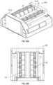
- FIGS. 6 - 18show a dispenser assembly 410 for dispensing a rolled sheet material 11 and a dispensing system or mechanism 450 for a dispenser according to another embodiment of the disclosure, which embodiment is generally similar to the prior embodiments except for variations noted and variations that will be apparent to one of ordinary skill in the art. Accordingly, similar or identical features of the embodiments have been given like or similar reference numbers.
- the dispenser assembly 410is similar to the dispenser assembly 10 of FIGS. 1 - 5 except that the dispensing system 450 includes a gear driven transmission assembly 462 ( FIGS. 10 and 14 - 18 ) rather than the belt driven transmission assembly 62 of the dispensing system 50 ( FIGS. 1 - 2 C ).
- the dispenser assembly 410can include the dispenser housing 12 having the cover 12 A that is movable/removable (e.g., FIG. 8 ) to allow access to the components of the dispenser assembly 410 , and the backing portion 12 B that is configured to mount or otherwise connect via, for example and without limitation, fasteners, adhesive, and the like, to the dispenser assembly 410 to a wall, partition, or other suitable support within a facility, such as a restroom, hospital room, and the like.
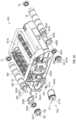
- the dispenser housing 12further includes the one or more chambers or compartments 13 defined therein and sized, dimensioned, and/or configured to receive and house the plurality of supplies 14 of sheet material 11 therein (e.g., the first supply 18 and the second supply 22 of sheet material).
- the dispenser housing 12also including a discharge 15 that facilitates dispensing of the sheet material 11 of the supplies of sheet material 14 from the dispenser assembly 410 .
- the dispensing system 450can include driven rollers 56 / 58 for engaging and driving the sheet material 11 from the supplies 18 / 22 of sheet material.
- the first supply 18 of sheet materialcan be dispensed by the corresponding first driven roller 56 and the second supply 22 of rolled sheet material can be dispensed by the corresponding second driven roller 58 similar or identical to prior embodiments.
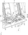
- the driven rollers 56 / 58can be mounted between a first end plate 451 A and a second end plate 451 B of the dispensing system 450 such as by exemplified bearing assemblies or other suitable features.
- the dispensing system 450can include guide rollers 442 A/ 444 A ( FIGS. 8 - 12 ) extending along the respective driven rollers 56 / 58 and guide rollers 442 B/ 444 B ( FIG. 12 ) extending along the respective driven rollers 56 / 58 .
- the guide rollers 442 A/ 444 A and 442 B/ 444 Bcan be mounted to the end plates 451 A/ 451 B in respective slots 453 (e.g., FIGS. 13 and 14 ) such as by the exemplified bearing assemblies or other suitable features mounted in the slots 453 .
- the bearingscan be movable along the slots 453 so that the guide rollers 442 A/ 444 A and 442 B/ 444 B can be operatively biased toward and/or against the respective driven rollers 56 / 58 such as, for example and without limitation, by springs or other suitable biasing members 466 that are configured to urge the bearings in the slots 453 toward the driven rollers 56 / 58 .
- the biasing members 466can be mounted to the end plates 451 A/ 451 B so that the biasing members press or are otherwise urged against the ends of the guide rollers (e.g., the bearing assemblies).
- the guide rollers 442 A/ 444 A and 442 B/ 444 Bcan press or otherwise engage the sheet material 11 against the respective driven rollers 56 / 58 as it passes between the driven rollers 56 / 58 and guide rollers 442 A/ 444 A and 442 B/ 444 B.
- the dispensing system 450can be configured to include any suitable number of guide or pressing rollers positioned adjacent the driven rollers 56 / 58 and/or guide rollers 442 A/ 444 A and 442 B/ 444 B to guide and/or engage the sheet material without departing from the scope of the present disclosure.
- the end plates 451 A/ 451 Bcan be connected by horizontal supports to form a support structure, which can be a unitary/integral structure or separate pieces coupled together.
- curved guide plates 455can be mounted between the end plates 451 A/ 451 B for guiding the sheet material 11 to the discharge 15 .
- the dispenser assembly 410can include a drive mechanism 460 operatively connected or coupled to the driven rollers 56 / 58 via a gear driven transmission assembly 462 to selectively drive rotation thereof.
- the drive mechanism 460can include a motor 60 A ( FIG. 12 ) or other suitable actuator and the driven rollers 56 / 58 are configured to rotate under the power of the drive mechanism 460 to pull the sheet material 11 from the respective supplies 18 / 22 and along the discharge paths at least partially defined between the driven rollers 56 / 58 and associated guide rollers 442 A/ 444 A and 442 B/ 444 B and through the discharge 15 defined in the dispenser housing 12 .
- the drive mechanism 460is configured to operatively communicate with a control circuitry (e.g., including controller 100 as shown in FIG. 5 ) of the dispenser assembly 410 to receive instructions and power for selectively activating and driving the driven rollers 56 / 58 of each roller assembly through a dispensing cycle (such as, for example and without limitation, a determined time, number of revolutions, and the like) to feed the selected or desired amount/length of the sheet material through the discharge 15 of the dispenser housing 12 .
- a control circuitrye.g., including controller 100 as shown in FIG. 5
- a dispensing cyclesuch as, for example and without limitation, a determined time, number of revolutions, and the like
- the motor 60 Acan be driven in a first direction, e.g., D 1 in FIG. 16 , to cause the transmission assembly 462 to engage and drive the first driven roller 56 and move the sheet material from the corresponding first supply 18 of sheet material along the first discharge path toward and out from the discharge 15 of the dispenser housing 12 .
- the motor 60 Acan be driven in a second direction, e.g., D 2 in FIGS. 17 and 18 , to cause the transmission assembly 462 to disengage with the first driven roller 56 and to engage and drive the second driven roller 58 and move the sheet material from the corresponding second supply 22 of sheet material along the second discharge path toward and out from the discharge 15 of the dispenser housing 12 .
- the gear driven transmission assembly 462can optionally also include a plurality of gears for transferring power from the drive mechanism 460 to a selective one of the driven rollers 56 / 58 .
- the transmission assembly 462can include a drive gear 471 mounted to the motor 60 A via a drive shaft extending through an opening in the first end plate 451 A of the dispensing system 450 .
- the drive gear 471can be driven to rotate on its axis by the motor 60 A directly or indirectly.
- the transmission assembly 462further can include an intermediate gear 464 coupled to the first end plate 451 A by a bearing 473 ( FIGS. 17 and 18 ) received in a transmission guide 475 mounted on the first end plate 451 A.
- the intermediate gear 464can rotate about its axis on the bearing 473 and the transmission guide 475 can define a path 477 (e.g., a curved path as shown in FIGS. 10 and 14 - 18 or any suitable path) between the driven rollers 56 / 58 .
- the intermediate gear 464can move/translate on its bearing 473 along the path 477 from a first end 477 A to a second end 477 B.
- the transmission guide 475can be made of a self-lubricating plastic or any suitable material.
- the drive gear 471can engage the intermediate gear 464 , wherein a plurality of teeth 471 A arranged along the circumference of the drive gear are configured to enmeshed with or otherwise engage a plurality of teeth 464 A arranged along the circumference of the intermediate gear 464 . It is contemplated that the curve of the path 477 in the transmission guide 475 can help retain the intermediate gear 464 in engagement with the drive gear 471 as the intermediate gear 464 translates along the path 477 .
- the transmission assembly 462further can include a first roller gear 467 mounted to a distal end of the first driven roller 56 and a second roller gear 469 mounted to a distal end of the second drive roller 58 .
- the roller gears 467 / 469can be coupled to the respective driven rollers 56 / 58 (e.g., by respective axles extending through respective openings in the first end plate 451 A) so that rotation of a selected one of the roller gears 467 / 469 causes the respective driven roller 56 / 58 to rotate on its axis.
- the first roller gear 467can be mounted proximate the first end 477 A of the transmission guide 475 so that the first roller gear 467 engages the intermediate gear 464 (e.g., teeth 467 A arranged along the circumference of the first roller gear 467 engage the teeth 464 A of the intermediate gear 464 ) when the intermediate gear 464 is at the first end 477 A of the transmission guide 475 .
- the intermediate gear 464e.g., teeth 467 A arranged along the circumference of the first roller gear 467 engage the teeth 464 A of the intermediate gear 464
- the second roller gear 469can be mounted proximate the second end 477 B of the transmission guide 475 so that the second roller gear 469 engages the intermediate gear 464 (e.g., teeth 469 A arranged along the circumference of the second roller gear 469 engage the teeth 464 A of the intermediate gear 464 ) when the intermediate gear 464 is at the second end 477 B of the transmission guide 475 .
- the intermediate gear 464e.g., teeth 469 A arranged along the circumference of the second roller gear 469 engage the teeth 464 A of the intermediate gear 464
- the motor 60 Acan rotate in the direction D 1 shown in FIG. 16 , rotating the drive gear 471 in the direction D 1 .
- the engagement between the intermediate gear 464 and the drive gear 471can urge the intermediate gear 464 toward the first end 477 of the transmission guide 475 and in engagement with the first roller gear 467 .
- the rotation of the drive gear 471is transmitted to the first roller gear 467 via the intermediate gear 464 so that the first driven roller 56 is rotated in the direction D 1 to draw the sheet material 11 between the first driven roller 56 and the guide rollers 442 A/ 442 B along the discharge path toward and out from the discharge 15 of the dispenser housing 12 .
- the transmission assembly 462can be operated to disengage the first driven roller 56 and engage the second driven roller 58 .
- the controller 100can reverse the direction of the motor 60 A (e.g., due to a signal from a supply sensor S 1 that the first supply of sheet material is depleted) so that the motor turns the drive gear 471 in the direction D 2 shown in FIG. 17 .
- the intermediate gear 464is moved along the path 477 in the transmission guide 475 in the direction of the arrow A, away from the first roller gear 467 and the first end 477 A of the path 477 by the drive gear 471 until the intermediate gear 464 reaches the second end 477 B of the path 477 and engages the second roller gear 469 .
- the transmission assembly 462can be operated to disengage the second driven roller 58 and engage the first driven roller 56 by reversing the above process (e.g., due to a signal produced by a supply sensor S 1 that indicates that the first supply of sheet material is depleted).
- FIGS. 19 A- 19 EAdditional views of the features of FIGS. 6 - 18 are shown in FIGS. 19 A- 19 E according to embodiments of the disclosure.
- the gear driven transmission assembly 462generally can have a quieter operation than belt driven transmissions. Further, in various aspects, the gear driven transmission assembly 462 can be more reliable, such as by reducing or eliminating slipping between components and/or using more durable components. Further, the gear driven transmission assembly 462 can reduce or eliminate the need for separate biasing apparatus since rotation of the drive gear 471 urges the intermediate gear 464 toward the first roller gear 467 or the second roller gear 469 in addition to rotating the intermediate gear 464 .
- FIGS. 20 A- 27 Bshow a dispensing system or mechanism 650 for a dispenser according to additional embodiments of the disclosure, which embodiments are generally similar to the prior embodiments except for variations noted and variations that will be apparent to one of ordinary skill in the art. Accordingly, similar or identical features of the embodiments have been given like or similar reference numbers.
- the dispensing system 450includes a belt driven transmission assembly 662 with two belts 664 A, 664 B selectively driven by a centrally located gear clutch assembly 671 mounted on a drive mechanism 660 .
- the belt driven transmission assembly 662can be mounted at an end wall or end plate 651 A of the dispensing system 650 and can include the two drive belts 664 A, 664 B operatively connecting or engaging the drive mechanism 660 and the driven rollers 56 , 58 to transfer power therebetween for selectively driving rotation of the first driven roller 56 and/or the second driven roller 58 , which driven rollers 56 , 58 can be supported between the end plate 651 A and an opposing end wall or end plate 651 B.
- the gear clutch assembly 671can be connected to the driven rollers 56 , 58 by the respective drive belts 664 A, 664 B, which can engage corresponding belt pulleys or belt gears 667 A, 667 B connected to the respective driven rollers 56 , 58 .
- the drive mechanism 660can include a motor 660 A (for example and without limitation, a brushless servo or stepper motor, or other, similar type of variable speed, reversible electric motor, or other suitable drive system) and a drive shaft 660 B.
- the drive shaft 660 Bcan include a proximal section 681 A spaced from a distal section 681 B by a recess 681 C or other suitable dividing feature.
- each of the respective proximal section 681 A and the distal section 681 Bcan be configured to operatively engage respective portions of the gear clutch assembly 671 .
- a C-clip 684can engage the recess 681 C and can extend between the portions of the gear clutch assembly 671 ( FIGS. 22 , 23 , 25 A , and 25 B) to help keep the portions of the gear clutch assembly 671 separate from one another.
- the drive shaft 660 Bcould be otherwise configured without departing from the disclosure.
- the recess 681 C and the C-clip 684could be omitted and/or the drive shaft 660 B can be stepped so that the distal section 681 B has a different diameter than the proximal section 681 A (e.g., the diameter of the distal section 681 B could be stepped up from the diameter of the proximal section 681 A or the diameter of the distal section 681 B could be stepped down from the diameter of the proximal section 681 A) to help keep the portions of the gear clutch assembly 671 separate.
- the drive motor 660 Acan be mounted in a defined interior chamber of the dispenser housing and on an interior side of the end plate 651 A, and the drive shaft 660 B can extend through the end plate 651 A (e.g., via a through-bore, a clearance opening, a bushing, a bearing, and/or other suitable features) to engage the gear clutch assembly 671 on the outer side of the end plate 651 A.
- the drive motor 660 Acould be mounted on the exterior side of the end plate 651 A.
- the gear clutch assembly 671can include a first or proximal drive pulley or drive gear 671 A engaging or mounted on the proximal section 681 A of the drive shaft 660 B and a second or distal drive pulley or drive gear 671 B engaging or mounted on the distal section 681 B of the drive shaft 660 B. As shown in FIGS. 21 A- 23 , 25 A, and 25 B , the gear clutch assembly 671 can include a first or proximal drive pulley or drive gear 671 A engaging or mounted on the proximal section 681 A of the drive shaft 660 B and a second or distal drive pulley or drive gear 671 B engaging or mounted on the distal section 681 B of the drive shaft 660 B. As shown in FIGS.
- the first drive belt 664 Aengages the proximal drive gear 671 A and the first belt gear 667 A so that they are rotatably coupled together by the first drive belt
- the second drive belt 664 Bengages the distal drive gear 671 B and the second belt gear 667 B so that they are rotatably coupled together by the second drive belt.
- the C-clip 684can be positioned between the drive gears 671 A, 671 B in the recess 681 C of the drive shaft 660 B so that the drive gears 671 A, 671 B are spaced from one another by at least the C-clip 684 .
- the gear clutch assembly 671can include or incorporate one or more clutch assemblies or mechanisms 670 ( FIG. 25 B ), such as hybrid or one-way clutch mechanisms, that allow for selective transfer of power between the drive mechanism 660 and the driven rollers 56 , 58 .
- the clutch mechanisms 670can be incorporated or integrated with the respective drive gears 671 A, 671 B. Accordingly, in operation, when the drive mechanism 660 is driven in a first direction D 1 ( FIGS.
- the clutch assembly 670 of the proximal drive gear 671 Awill lock/engage for transfer of power/torque to the first driven roller 56 (e.g., via the first drive belt 664 A and the first belt gear 667 A) so that the first driven roller 56 is driven by the drive mechanism 660 and rotated to dispense its corresponding supply of sheet material (while the clutch assembly 670 of the distal drive gear 671 B remains generally disengaged).
- the drive mechanism 660is driven in the opposite direction D 2 ( FIGS.
- the clutch assembly 670 of the proximal drive gear 671 Awill unlock or disengage such that there is no transfer of power/torque between the drive mechanism 660 and the first driven roller 56 (while the clutch assembly 670 for the distal drive gear 671 B engages or locks for transfer of power/torque to the second driven roller 58 , e.g., via the second drive belt 664 B and the second belt gear 667 B, so that the second driven roller 58 is rotated to dispense its corresponding supply of sheet material).
- each clutch assembly 670can include one or more tracks/races, such as an inner race 672 and an outer race 674 , that rotate together (when engaged) or independently of one another (when disengaged).
- the inner and outer races 672 , 674 of the clutch assemblies 670can be configured in a similar or identical manner as the inner and outer races 72 , 74 of FIG. 2 B .
- one or both of the clutch assemblies 670could be otherwise configured without departing from the scope of the application.
- both of the inner races 672 of the drive gears 671 A, 671 Bare turned by the drive shaft 660 B when the motor 660 A turns the drive shaft in either direction D 1 , D 2 .
- the clutch assemblies 670are configured so that, when the drive shaft 660 B is turned in the direction D 1 , only the clutch assembly 670 of the proximal drive gear 671 A engages to cause the outer race 674 to turn with the inner race 672 , thereby moving the first drive belt 664 A, which turns the first belt gear 667 A and the first driven roller 56 .
- the clutch assembly 670 of the distal drive gear 671 Bis disengaged so that the inner race 672 and the outer race 674 are able to rotate independently when the drive shaft 660 B is rotated in the direction D 1 and the outer race 674 does not rotate with the inner race 672 so that the second drive belt 664 B, the second belt gear 667 B, and the second driven roller 58 are not turned.
- the drive shaft 660 Bis operationally turned in the direction D 2
- only the clutch assembly 670 of the distal drive gear 671 Bengages to cause the outer race 674 to turn with the inner race 672 , thereby moving the second drive belt 664 B, which turns the second belt gear 667 B and the second driven roller 58 .
- the clutch assembly 670 of the proximal drive gear 671 Ais disengaged so that the inner race 672 and the outer race 674 are able to rotate independently when the drive shaft 660 B is rotated in the direction D 2 and the outer race 674 does not rotate with the inner race 672 so that the first drive belt 664 A, the first belt gear 667 A, and the first driven roller 56 are not turned.
- the proximal and distal drive gears 671 A, 671 Bcan be similar or identical to one another and can be mounted on the drive shaft 660 B in opposite orientations ( FIGS. 22 , 23 , 25 A, and 25 B ).
- the drive gears 671 A, 671 Bcould be configured differently.
- each of the roller extensions 668includes a cylindrical portion 668 A that is supported in a respective opening 686 of the end plate 651 A by a bearing 686 A and/or a bushing 686 B (e.g., the cylindrical portion 668 A engages an inner race of the bearing 686 A or an inner surface of the bushing 686 B).
- a distal section 668 B of the roller extension 668can be configured to mate with or otherwise engage a central bore 687 of the respective belt gear 667 A, 667 B.
- the distal section 668 Bcan have a flat surface 668 C on either side of the roller extension 668 , and the flat surfaces 668 C can engage respective flat surfaces on the interior surface of the belt gear extending along the central bore 687 . Accordingly, operable rotation of the belt gears 667 A, 667 B can cause the respective roller extension 668 to turn, thereby turning the respective driven roller 56 , 58 .
- the belt gears 667 A, 667 Bcan be similar or identical to one another and can be mounted on the respective roller extensions 668 in opposite orientations in order to align the belt engaging portions of the belt gears 667 A, 667 B with the respective drive gears 671 A, 671 B.
- each of the belt gears 667 A, 667 Bcan include a spacer portion 688 .
- the second belt gear 667 Bcan be oriented so that the spacer portion 688 is positioned between the belt engaging portion of the belt gear and the end plate 651 A, and the spacer portion 688 of the first belt gear 667 A is spaced from the end plate 651 A by the belt engaging portion of the belt gear.
- the belt gears 667 A, 667 Bcould be otherwise configured and/or could be optionally configured different from one another (e.g., the spacer portion 688 could be omitted on the first belt gear 667 A).
- the transmission assembly 662 of FIGS. 20 A- 27 Bcan be easier to assemble due to the central location of the gear clutch assembly 671 .
- the belt gears 667 A, 667 B, located at the outer portions of the transmission assemblycan be desirably made of lighter, cheaper materials (e.g., plastic instead of metal).
- the configuration of the transmission assembly 662can be quieter and can increase the efficiency of the dispensing system 650 .
- FIGS. 28 A and 28 Bshow views of other optional embodiments of a dispensing system 650 ′
- FIGS. 28 C and 28 Dshow views of other optional embodiments of a drive mechanism 660 ′.
- the sheet material dispensercan include a dispenser housing with a first and a second supply of sheet material supported therein and including a first driven roller rotatably mounted within the dispenser housing that is configured to drive sheet material from the first supply of sheet material and a second driven roller rotatably mounted within the dispenser housing that is configured to drive sheet material from the second supply of sheet material.
- the sheet material dispenserfurther can include a drive mechanism operably coupled to a select one of the first or second driven roller to selectively drive rotation of the select one of the first or the second driven roller.
- the drive mechanismcomprises a transmission assembly configured to selectively drive rotation of the select one of the first or the second driven roller; and a motor configured to drive in a first rotation direction to cause the transmission assembly to disengage with the second driven roller and engage and rotate the first driven roller to affect the movement of the sheet material from the first supply of sheet material along a first discharge path toward and out from a discharge defined in the dispenser housing.
- the motoris further configured to drive in a second rotation direction, opposite to the first rotation direction, to cause the transmission assembly to disengage with the first driven roller and to engage and rotate the second driven roller to affect the movement of sheet material from the second supply of sheet material along a second discharge path toward and out from the discharge of the dispenser housing.
- the sheet material dispensercan further include a control circuitry in communication with the drive mechanism that is programmed to selectively actuate the motor in the first or second rotative direction to feed the sheet material from the selected supply of sheet material through the discharge defined in the dispenser housing.
- the transmission assembly of the sheet material dispensercan include a plurality of gears for transferring power from the drive mechanism to a select one of the first or the second driven roller.
- the plurality of gearscan comprise a drive gear, an intermediate gear, a first roller gear, and a second roller gear.
- the drive gearis mounted to the motor and the intermediate gear is configured to be slidably received within a transmission guide defined in the first end plate of the housing that extends along a path between the respective first and second driven rollers.
- the intermediate gearis positioned in engagement with the drive gear and rotates in a direction that is in opposition to the select first or second rotation direction of the motor.
- first roller gearis mounted to a distal end of the first driven roller and the second roller gear is mounted to a distal end of the second drive roller.
- selective rotation of a respective first or second roller gearaffects a complementary rotation of the coupled first or second driven roller.
- first roller gearis mounted proximate a first end of the transmission guide so that the first roller gear is configured to engage the intermediate gear when the intermediate gear is at the first end of the transmission guide.
- second roller gearis mounted proximate a second end of the transmission guide so that the second roller gear is configured to engage the intermediate gear when the intermediate gear is at the second end of the transmission guide.
- the sheet material dispensercan further include a first guide roller and a second guide roller.
- the dispenser housinghas a first end plate and a second, spaced and opposed, end plate and, as shown, each respective end plate can define a slot.
- the first and second guide rollerscan be configured for mounting therein the respective slots of the first and second end plates and can be further configured for biased movement along the respective slots of the first and second end plates such that the respective first and second guide rollers are urged toward the respective first and second driven rollers.
- each of the first and second guide rollerscan include a pair of bearing assemblies positioned so that one bearing assembly of the pair of bearing assemblies can be positioned at a proximal end of the respective guide roller and another bearing assembly of the pair of bearing assemblies can be positioned at a distal end of the respective guide roller.
- the sheet material dispensercan include a first biasing member mounted within the dispenser housing that is configured to urge the first guide roller along the slots and toward the first driven roller and a second biasing member mounted within the dispenser housing configured to urge the second guide roller along the slots and toward the second driven roller.
- the sheet material dispensercan include a dispenser housing, a first driven roller, a second driven roller, a drive mechanism, and a control circuitry.
- the dispenser housinghas a first and a second supply of sheet material supported therein the housing.
- the first driven rolleris configured to be rotatably mounted within the dispenser housing to drive sheet material from the first supply of sheet material and, similarly, the second driven roller is configured to be rotatably mounted within the dispenser housing to drive sheet material from the second supply of sheet material.
- the drive mechanismis operably coupled to a select one of the first or second driven roller to selectively drive rotation of the select one of the first or the second driven roller.
- the drive mechanismcomprises a motor and a plurality of gears.
- the motorconfigured to drive in a first rotation direction and further configured to drive in a second rotation direction, opposite to the first rotation direction.
- the plurality of gears for transferring power from the drive mechanism to the select one of the first or the second driven rollerincludes a drive gear, an intermediate gear, a first roller gear and a second roller gear.
- the drive gearis mounted to the motor and the intermediate gear is configured to be slidably received within a transmission guide defined in the first end plate of the housing that extends along a path between the respective first and second driven rollers.
- the intermediate gearis positioned in engagement with the drive gear and rotates in a direction that is in opposition to the select first or second rotation direction of the motor.
- the exemplary control circuitryis in communication with the drive mechanism and is programmed to selectively actuate the motor in the first or second rotative direction to feed the sheet material from the selected supply of sheet material through the discharge defined in the dispenser housing.
- the intermediate gearengages with the first roller gear and disengages from the second roller gear to affect the rotation of the first driven roller and to affect movement of sheet material from the first supply of sheet material along a first discharge path toward and out from the discharge.
- the intermediate geardisengages with the first roller gear and engages with the second roller gear to affect the rotation of the second driven roller and to affect movement of sheet material from the second supply of sheet material along a second discharge path toward and out from the discharge of the dispenser housing.
- the first roller gearis mounted proximate a first end of the transmission guide so that the first roller gear is configured to engage the intermediate gear when the intermediate gear is at the first end of the transmission guide
- the second roller gearis mounted proximate a second end of the transmission guide so that the second roller gear is configured to engage the intermediate gear when the intermediate gear is at the second end of the transmission guide.
- the sheet material dispensercan include a dispenser housing, a first driven roller, a second driven roller, and a drive mechanism operably coupled the first and second driven rollers.
- the dispenser housinghas a first and a second supply of sheet material supported therein.
- the first driven rolleris configured to be rotatably mounted within the dispenser housing to drive sheet material from the first supply of sheet material
- the second driven rolleris configured to be rotatably mounted within the dispenser housing to drive sheet material from the second supply of sheet material.
- the sheet material dispensercan further include a control circuitry in communication with the drive mechanism that is programmed to selectively actuate the motor in the first or second rotative direction to feed the sheet material from the selected supply of sheet material through the discharge defined in the dispenser housing.
- the drive mechanismcan include a motor, a first and second belt gear, a first and second drive gear, and respective first and second drive belts, and a plurality of clutch assemblies.
- the motoris configured to drive in a first rotation direction and in a second, opposite, rotation direction and further has a drive shaft that has a proximal section and a spaced distal section.
- the first belt gearis coupled to the first driven roller and the second belt gear is coupled to the second driven roller.
- the first drive gearis mounted on the proximal section of the drive shaft and the second drive gear is mounted on the distal section of the drive shaft.
- the first drive beltis configured to engage the first belt gear and the first drive gear and similarly, the second drive belt is configured to engage the second belt gear and the second drive gear.
- At least one clutch assembly of the a plurality of clutch assembliesis configured to be operably integrated with the first drive gear and at least one clutch assembly configured to be operably integrated with the second drive gear.
- the at least one clutch assembly that is configured to be operably integrated with the first drive geardisengages from the second drive gear and operatively engages the first drive gear to affect transfer of torque to the first drive gear so that the first driven roller is driven by the first drive belt and first drive gear to rotate and dispense its supply of sheet material.
- the at least one clutch assemblythat is configured to be operably integrated with the second drive gear disengages from the first drive gear and operatively engages the second drive gear to affect transfer of torque to the second drive gear so that the first driven roller is driven by the second drive belt and second drive gear to rotate and dispense its supply of sheet material.
- each clutch assemblycan include an inner race and an outer race that are configured to rotate together when the clutch assembly is engaged and are configured to act independently of one another when the clutch assembly is disengaged.
- each clutch assemblyis configured so that the at least one clutch assembly integrated with the first drive gear engages to cause the respective clutch assembly outer race to turn with the inner race, affecting movement of the first drive belt and rotation of the first belt gear and the first driven roller.
- the at least one clutch assembly integrated with the second drive gearis disengaged so that the respective clutch assembly inner race and the outer race rotate independently of each other such that the outer race does not rotate with the inner race and no movement is affected on the second drive belt.
- each clutch assemblywhen the drive shaft is turned in the second rotative direction, each clutch assembly is configured so that only the at least one clutch assembly integrated with the second drive gear engages to cause the respective clutch assembly outer race to turn with the inner race, affecting movement of the second drive belt and rotation of the second belt gear and the second driven roller.
- the at least one clutch assembly integrated with the first drive gearis disengaged so that the respective clutch assembly inner race and the outer race rotate independently of each other such that the outer race does not rotate with the inner race and no movement is affected on the first drive belt.
Landscapes
- Health & Medical Sciences (AREA)
- Public Health (AREA)
- Delivering By Means Of Belts And Rollers (AREA)
Abstract
Description
Claims (19)
Priority Applications (2)
| Application Number | Priority Date | Filing Date | Title |
|---|---|---|---|
| US18/107,260US12329327B2 (en) | 2022-02-08 | 2023-02-08 | Sheet material dispenser assembly for selectively dispensing sheet material from a plurality of supplies of rolled sheet material |
| US19/212,950US20250275654A1 (en) | 2022-02-08 | 2025-05-20 | Sheet material dispenser assembly for selectively dispensing sheet material from a plurality of supplies of rolled sheet material |
Applications Claiming Priority (3)
| Application Number | Priority Date | Filing Date | Title |
|---|---|---|---|
| US202263307699P | 2022-02-08 | 2022-02-08 | |
| US202263337371P | 2022-05-02 | 2022-05-02 | |
| US18/107,260US12329327B2 (en) | 2022-02-08 | 2023-02-08 | Sheet material dispenser assembly for selectively dispensing sheet material from a plurality of supplies of rolled sheet material |
Related Child Applications (1)
| Application Number | Title | Priority Date | Filing Date |
|---|---|---|---|
| US19/212,950ContinuationUS20250275654A1 (en) | 2022-02-08 | 2025-05-20 | Sheet material dispenser assembly for selectively dispensing sheet material from a plurality of supplies of rolled sheet material |
Publications (2)
| Publication Number | Publication Date |
|---|---|
| US20230248189A1 US20230248189A1 (en) | 2023-08-10 |
| US12329327B2true US12329327B2 (en) | 2025-06-17 |
Family
ID=87521973
Family Applications (2)
| Application Number | Title | Priority Date | Filing Date |
|---|---|---|---|
| US18/107,260Active2043-09-09US12329327B2 (en) | 2022-02-08 | 2023-02-08 | Sheet material dispenser assembly for selectively dispensing sheet material from a plurality of supplies of rolled sheet material |
| US19/212,950PendingUS20250275654A1 (en) | 2022-02-08 | 2025-05-20 | Sheet material dispenser assembly for selectively dispensing sheet material from a plurality of supplies of rolled sheet material |
Family Applications After (1)
| Application Number | Title | Priority Date | Filing Date |
|---|---|---|---|
| US19/212,950PendingUS20250275654A1 (en) | 2022-02-08 | 2025-05-20 | Sheet material dispenser assembly for selectively dispensing sheet material from a plurality of supplies of rolled sheet material |
Country Status (4)
| Country | Link |
|---|---|
| US (2) | US12329327B2 (en) |
| EP (1) | EP4476154A1 (en) |
| DE (1) | DE23753402T1 (en) |
| WO (1) | WO2023154343A1 (en) |
Families Citing this family (5)
| Publication number | Priority date | Publication date | Assignee | Title |
|---|---|---|---|---|
| CA3124998A1 (en) | 2019-01-02 | 2020-07-09 | Charles Agnew Osborne, Jr. | Power management system for dispensers |
| CA3142926A1 (en) | 2019-06-14 | 2020-12-17 | Charles Agnew Osborne, Jr. | Loading and transfer system/assembly for sheet material dispensers |
| WO2021154286A1 (en)* | 2020-01-31 | 2021-08-05 | Kimberly-Clark Worldwide, Inc. | Paper product dispenser with improved dispensing |
| KR102648621B1 (en)* | 2020-05-13 | 2024-03-15 | 코어렉스신에이가부시키가이샤 | toilet paper holder |
| US12384628B2 (en)* | 2023-05-09 | 2025-08-12 | Intelligrated Headquarters, Llc | Methods, systems, and assemblies for power generation for a material handling system |
Citations (250)
| Publication number | Priority date | Publication date | Assignee | Title |
|---|---|---|---|---|
| US2299301A (en) | 1940-10-29 | 1942-10-20 | Thomas J Britt | Automatic roll dispenser |
| US2549912A (en) | 1947-04-21 | 1951-04-24 | Lionel G Lindsay | Supporting structure for a plurality of rolls |
| US2826373A (en) | 1955-07-05 | 1958-03-11 | Franics H Schwartz | Intermittent motion mechanism |
| US2840319A (en) | 1956-05-02 | 1958-06-24 | J E Wade | Storage and dispensing receptacle for rolled paper |
| US3007650A (en) | 1959-01-12 | 1961-11-07 | Crown Zellerbach Corp | Two-roll towel dispensing cabinet |
| US3010670A (en) | 1958-08-19 | 1961-11-28 | American Can Co | Dispenser for toilet tissue rolls |
| US3132782A (en) | 1961-11-28 | 1964-05-12 | Jr Robert N Coates | Dispenser for rolled materials |
| US3387902A (en) | 1967-01-03 | 1968-06-11 | Towlsaver Inc | Dispenser for sequentially dispensing rolls of tissue and the like |
| US3572600A (en) | 1968-02-09 | 1971-03-30 | Georgia Pacific Corp | Dispenser for rolls of flexible sheet material having structurally rigid internal supporting means |
| US3637276A (en) | 1970-06-15 | 1972-01-25 | Vaughan Mfg Co | Dispenser |
| US3650487A (en) | 1970-03-06 | 1972-03-21 | Steiner American Corp | Two-roll tissue dispenser |
| US3677485A (en) | 1970-08-19 | 1972-07-18 | Fleck Ind Inc | Paper roll dispenser |
| US3690580A (en) | 1970-05-13 | 1972-09-12 | Paul W Jespersen | Dispenser for convention rolls of flexible sheet material |
| US3698653A (en) | 1971-05-05 | 1972-10-17 | Tadasu Okamura | Toilet paper roll holding device |
| US3700181A (en) | 1971-06-24 | 1972-10-24 | Mosinee Paper Corp | Tissue dispensing mechanism |
| US3737087A (en) | 1972-05-24 | 1973-06-05 | Mirra Cote Co Inc | Dispensing apparatus for rolled materials |
| US3754719A (en) | 1971-04-26 | 1973-08-28 | S Choy | Roll paper dispensers |
| US3770222A (en) | 1970-05-13 | 1973-11-06 | Georgia Pacific Corp | Dispenser for rolls of flexible sheet material having means for holding a roll in a reserve position |
| US3771739A (en) | 1971-05-03 | 1973-11-13 | Bobrick Corp | Roll paper dispenser |
| US3865295A (en) | 1972-12-29 | 1975-02-11 | Tadasu Okamura | Toilet paper roll holding device |
| US3948454A (en) | 1974-12-03 | 1976-04-06 | Scott Paper Company | Dispenser for multiple rolls of sheet material |
| US4108389A (en) | 1977-11-07 | 1978-08-22 | Womack Rolla J | Dispenser for a plurality of rolls of sheet material |
| US4113195A (en) | 1976-11-24 | 1978-09-12 | Manfred Sidley | Dispensing device for web material in roll form |
| US4143827A (en) | 1978-05-22 | 1979-03-13 | Towlsaver, Inc. | Roll holder for mounting split-core rolls of tissue in a dispenser |
| US4148442A (en) | 1977-04-19 | 1979-04-10 | Apura Gmbh | Device for dispensing sheets of web material of predetermined length |
| US4165138A (en) | 1976-11-15 | 1979-08-21 | Mosinee Paper Company | Dispenser cabinet for sheet material and transfer mechanism |
| US4260117A (en) | 1979-11-15 | 1981-04-07 | Towlsaver, Inc. | Dual roll towel dispenser |
| US4285474A (en) | 1980-03-27 | 1981-08-25 | Perez Michael A | Toilet paper dispenser with biasing means for restraining the unwinding of the paper |
| US4307638A (en) | 1978-05-22 | 1981-12-29 | Georgia-Pacific Corporation | Method of dispersing flexible sheet material |
| US4340195A (en) | 1979-07-19 | 1982-07-20 | Georgia-Pacific Corporation | Dispenser for rolled flexible sheet material |
| US4363454A (en) | 1980-08-21 | 1982-12-14 | Louis Mohar | Tissue roll storage and dispenser apparatus |
| US4375874A (en) | 1981-03-05 | 1983-03-08 | Bradley Corporation | Rolled tissue dispenser |
| US4422584A (en) | 1981-10-09 | 1983-12-27 | Wisconsin Tissue Mills, Inc. | Toilet paper dispenser with swinging mandrels |
| US4422585A (en) | 1981-09-21 | 1983-12-27 | Alwin Manufacturing Company, Inc. | Toilet paper dispenser with sliding mandrels |
| US4432482A (en) | 1981-04-17 | 1984-02-21 | Beausoleil Armand S | Dispenser for rolled sheet material |
| US4487375A (en) | 1983-02-16 | 1984-12-11 | Georgia-Pacific Corporation | Roll transfer mechanism for web material dispenser |
| US4520968A (en) | 1982-10-20 | 1985-06-04 | David Shpigelman | Dispensing device for cylindrical bodies, such as rolls of toilet paper, paper towels and the like |
| US4552315A (en) | 1983-01-13 | 1985-11-12 | Maurice Granger | Rolled web dispenser |
| US4564148A (en) | 1984-06-25 | 1986-01-14 | Wentworth Michael B | Toilet paper dispensing system |
| US4634192A (en) | 1984-07-24 | 1987-01-06 | Dudley Industries Limited | Roller towel apparatus |
| US4765475A (en) | 1986-12-11 | 1988-08-23 | Kaysserian Kerry M | Holder and dispenser for multiple rolls of tissue |
| US4796832A (en) | 1987-03-02 | 1989-01-10 | James River Ii, Inc. | Dispenser for jumbo roll of toilet tissue |
| US4807823A (en) | 1986-02-18 | 1989-02-28 | Wyant & Company Limited/La Compagnie Wyant Limitee | Bathroom tissue dispenser |
| US4830301A (en) | 1987-12-22 | 1989-05-16 | Miller Robert B | Rolled toilet tissue holder and housing for extra roll |
| US4836462A (en) | 1988-10-21 | 1989-06-06 | Bruss Elroy A | Toilet tissue dispenser |
| US4872601A (en) | 1987-09-04 | 1989-10-10 | Scott Paper Company | Two large roll toilet tissue dispenser |
| US4879150A (en) | 1987-03-02 | 1989-11-07 | James River Ii, Inc. | Jumbo roll of toilet tissue |
| US4944466A (en) | 1988-07-14 | 1990-07-31 | Georgia-Pacific Corporation | Flexible sheet material dispenser with automatic roll transferring mechanism |
| US5000393A (en) | 1989-09-22 | 1991-03-19 | Rollar Corporation | Dispenser for rolls of sheet material |
| US5009313A (en) | 1989-08-16 | 1991-04-23 | Wyant & Company Limited | Bathroom tissue dispenser (spindle release) |
| EP0452577A1 (en) | 1990-04-18 | 1991-10-23 | WYANT & COMPANY LIMITED | Bathroom tissue dispenser (large roll) |
| KR930006227Y1 (en) | 1991-06-11 | 1993-09-15 | 주식회사 신도리코 | Thermal Transfer Fax Ink Sheet Drives |
| US5265816A (en) | 1992-08-07 | 1993-11-30 | Fort Howard Corporation | Double roll tissue dispenser with sliding door |
| US5271574A (en) | 1991-08-28 | 1993-12-21 | Georgia-Pacific Corporation | Dispenser for flexible sheet material |
| GB2269361A (en) | 1992-08-07 | 1994-02-09 | Fort Howard Corp | Successive dispensing from two sheet rolls |
| US5295638A (en) | 1992-03-31 | 1994-03-22 | Daewoo Electronics Co., Ltd. | Reel driving apparatus for a videocassette recorder |
| US5314131A (en) | 1993-01-04 | 1994-05-24 | Georgia-Pacific Corporation | Apparatus for dispensing rolled flexible sheet material |
| US5370336A (en) | 1993-06-04 | 1994-12-06 | James River Paper Company, Inc. | Dispenser apparatus for sequentially dispensing from coreless rolls of sheet material |
| US5400982A (en) | 1992-05-28 | 1995-03-28 | Fort Howard Corporation | Dispenser for multiple rolls of sheet material |
| US5449127A (en) | 1993-12-14 | 1995-09-12 | Davis; Robert T. | Dispenser for rolls of sheet material |
| EP0522477B1 (en) | 1991-07-12 | 1995-10-18 | von Lepel, Freifrau, Barbara | Towel dispenser with paper |
| JPH07275161A (en) | 1994-04-11 | 1995-10-24 | Akira Hida | Toilet paper holder for preventing mischief |
| US5558302A (en) | 1995-02-07 | 1996-09-24 | Georgia-Pacific Corporation | Flexible sheet material dispenser with automatic roll transferring mechanism |
| US5577634A (en) | 1994-06-16 | 1996-11-26 | G. H. Wood & Wyant, Inc. | Paper towel dispenser for dispensing towelling from inside diameter of roll |
| US5628474A (en) | 1995-08-02 | 1997-05-13 | Alwin Manufacturing Co. | Spring biased automatic multi roll paper dispenser |
| US5636812A (en) | 1995-03-10 | 1997-06-10 | Kimberly-Clark Corporation | Dispensing apparatus |
| US5645244A (en) | 1996-03-05 | 1997-07-08 | James River Corporation Of Virginia | Dispenser apparatus for dispensing paper sheet material |
| US5669576A (en) | 1995-08-10 | 1997-09-23 | James River Corporation Of Virginia | Apparatus for supporting coreless rolls in toilet tissue dispenser |
| US5690299A (en) | 1996-11-12 | 1997-11-25 | Perrin Manufacturing | Dispenser for feeding sheet material from sequential rolls |
| JPH1014819A (en) | 1996-07-09 | 1998-01-20 | Tooyo:Kk | Sheet roll holder |
| US5749538A (en) | 1995-08-02 | 1998-05-12 | Kimberly-Clark Corp. | Gravity-operated dispensing apparatus |
| US5813624A (en) | 1996-10-10 | 1998-09-29 | Fort James Corporation | Apparatus for dispensing toilet tissue from rolls |
| US5868335A (en) | 1997-09-09 | 1999-02-09 | Lebrun; Camil | Tissue roll dispenser |
| US5873542A (en) | 1996-11-12 | 1999-02-23 | Perrin Manufacturing | Dispenser for feeding sheet material from sequential rolls |
| US5954256A (en) | 1996-05-02 | 1999-09-21 | Qts S.R.L. | Dispenser for dispensing paper upon manual tearing from a roll, wherein the dispenser is provided with a second roll in reserve |
| US6027002A (en) | 1995-10-10 | 2000-02-22 | Granger; Maurice | Paper towelling dispenser with spare roll loading device |
| WO2000035328A1 (en) | 1998-12-14 | 2000-06-22 | Kimberly-Clark Worldwide, Inc. | Surface unwind jumbo roll tissue dispenser |
| US6082664A (en) | 1997-11-20 | 2000-07-04 | Kimberly-Clark Worldwide, Inc. | Coreless roll product and adapter |
| US6092759A (en) | 1997-09-08 | 2000-07-25 | Kimberly-Clark Worldwide, Inc. | System for dispensing coreless rolls of product |
| EP1033100A2 (en) | 1999-03-04 | 2000-09-06 | Fort James Corporation | Dispenser for dispensing toilet tissue from rolls |
| US6138939A (en) | 1998-08-17 | 2000-10-31 | Kimberly Clark Worldwide, Inc. | Coreless adapter for dispensers of cored rolls of material |
| US6152397A (en) | 1998-10-30 | 2000-11-28 | Kimberly-Clark Worldwide Inc. | Spacing member for a sheet material dispenser |
| US6189828B1 (en) | 1999-11-08 | 2001-02-20 | Robert Reilly | Sanitary paper roll dispenser |
| US6290169B1 (en) | 2000-06-13 | 2001-09-18 | Linda Sue Hartley | Free standing paper towel dispensing apparatus |
| US6315237B1 (en) | 1999-02-17 | 2001-11-13 | Darrell Hoerner | Wall-mounted rolled material dispensing and storage |
| US6328255B1 (en) | 2000-06-05 | 2001-12-11 | Fort James Corporation | Method and apparatus for converting a toilet tissue roll dispenser from a concurrent-roll dispensing mode to a sequential-roll dispensing mode |
| US6364245B1 (en) | 2000-03-28 | 2002-04-02 | Alwin Manufacturing Co., Inc. | Toilet roll dispenser for different diameter core rolls |
| US6363824B1 (en) | 1997-12-01 | 2002-04-02 | Maurice Granger | Paper-wipe dispensing machine |
| US6382553B1 (en) | 2000-10-31 | 2002-05-07 | Kimberly Clark Worldwide, Inc. | Stackable coreless roll carriage unit adapter for dispensers |
| US6405972B1 (en) | 1999-05-18 | 2002-06-18 | Bonaventure J. Wakam | Toilet paper roll storage and dispenser |
| US6409120B1 (en) | 2000-03-29 | 2002-06-25 | Kimberly-Clark Worldwide, Inc. | Dispenser apparatus and method |
| US6412679B2 (en) | 1998-05-20 | 2002-07-02 | Georgia-Pacific Corporation | Paper towel dispenser |
| US6422503B1 (en) | 2001-05-29 | 2002-07-23 | Michele Renee Hoo Kong | Toilet paper roll dispenser |
| US6426701B1 (en) | 2000-09-20 | 2002-07-30 | Ultraclenz Engineering Group | Handwash monitoring system |
| US6491251B1 (en) | 2000-03-09 | 2002-12-10 | Bay West Paper Corporation | Double core tissue roll, dispenser and method |
| US6520372B2 (en) | 2000-12-19 | 2003-02-18 | Kimberly-Clark Worldwide, Inc. | Folded sheet dispenser having an overfill prevention device |
| US6527219B1 (en) | 2002-02-15 | 2003-03-04 | James A. Trecartin | Toilet paper dispensing system |
| US6550714B1 (en) | 1998-05-25 | 2003-04-22 | Maurice Granger | Wiping material dispensing apparatus |
| US6561378B1 (en) | 2000-08-02 | 2003-05-13 | Kimberly Clark Co | Tissue dispensing apparatus |
| US20030110911A1 (en) | 2001-12-19 | 2003-06-19 | Kimberly-Clark Worldwide, Inc. | Electro-mechanical roll product dispenser |
| US6592067B2 (en) | 2001-02-09 | 2003-07-15 | Georgia-Pacific Corporation | Minimizing paper waste carousel-style dispenser apparatus, sensor, method and system with proximity sensor |
| US20030146337A1 (en) | 2001-12-20 | 2003-08-07 | Moody John R. | Support sled for rolls of absorbent sheet and dispenser incorporating same |
| US6607160B2 (en) | 2001-07-30 | 2003-08-19 | Kimberly-Clark Worldwide | Easy loading dispenser |
| US20030168550A1 (en) | 2002-03-07 | 2003-09-11 | Georgia-Pacific Corporation | Apparatus and methods usable in connection with dispensing flexible sheet material from a roll |
| US20040004152A1 (en) | 2002-07-03 | 2004-01-08 | Kapiloff David W. | Dispenser for multiple rolls of sheet material |
| US6679409B2 (en) | 1999-03-03 | 2004-01-20 | Sca Hygiene Products Ab | Dispenser for rolls of web-shaped material |
| US6685074B2 (en) | 1998-02-02 | 2004-02-03 | Fort James Corporation | Sheet material dispensing apparatus and method |
| US6691597B2 (en) | 1999-10-26 | 2004-02-17 | Maurice Granger | Dispensing machine for wipe material |
| US6702225B2 (en) | 1999-04-30 | 2004-03-09 | Kimberly-Clark Worldwide, Inc. | Dispenser and tray for premoistened wipes |
| US6715637B1 (en) | 2001-09-28 | 2004-04-06 | Amando C. Ramos | Combination storage/dispenser for hollow-cored paper roll |
| US6736466B1 (en) | 2002-08-27 | 2004-05-18 | Steven R. Helland | Paper towel dispensing apparatus |
| US6736348B1 (en) | 2000-06-28 | 2004-05-18 | Georgia-Pacific Corporation | Power transfer system apparatus |
| US6786448B2 (en) | 2002-06-07 | 2004-09-07 | Damian Arcilesi | Fixed-spool toilet paper dispenser with removable outer bracket and method |
| US6826991B1 (en) | 1999-11-08 | 2004-12-07 | Georgia-Pacific Corporation | Web transfer mechanism for flexible sheet dispenser |
| US6903654B2 (en) | 2002-06-03 | 2005-06-07 | Alwin Manufacturing Company, Inc. | Automatic dispenser apparatus |
| US6902134B2 (en) | 2002-09-12 | 2005-06-07 | Kimberly-Clark Worldwide, Inc. | Dispenser for rolled paper |
| US6915935B2 (en) | 2002-07-02 | 2005-07-12 | Arkady Portnoy | Sheet dispensing system for rolled materials |
| US6920999B2 (en) | 2002-10-30 | 2005-07-26 | Kimberly-Clark Worldwide, Inc. | Folded sheet dispenser having an overfill prevention mechanism |
| US20050167541A1 (en) | 2004-01-30 | 2005-08-04 | Osborne Charles A. | Intelligent dispensing system |
| US20050171634A1 (en) | 2003-12-31 | 2005-08-04 | Kimberly-Clark Worldwide, Inc. | System and method for measuring, monitoring and controlling washroom dispensers and products |
| US6959891B2 (en) | 2002-07-03 | 2005-11-01 | Kimberly-Clark Worldwide, Inc. | Dispenser for multiple rolls of sheet material |
| US6977588B2 (en) | 2002-06-03 | 2005-12-20 | Alwin Manufacturing Co. | Automatic dispenser apparatus |
| US7014140B2 (en) | 2004-01-30 | 2006-03-21 | Bay West Paper Corporation | Three roll tissue dispenser |
| US7040566B1 (en) | 2003-04-08 | 2006-05-09 | Alwin Manufacturing Co., Inc. | Dispenser with material-recognition apparatus and material-recognition method |
| US7066423B2 (en) | 2002-12-19 | 2006-06-27 | Sca Hygiene Products Ab | Solid rolls dispenser |
| US7083138B2 (en) | 2004-01-29 | 2006-08-01 | Bay West Paper Corporation | Two roll paper web material dispenser |
| US7093737B2 (en) | 2003-04-16 | 2006-08-22 | Kimberly-Clark Worldwide, Inc. | Container and cartridge for dispensing paper products |
| US7124911B2 (en) | 2003-04-16 | 2006-10-24 | Kimberly-Clark Worldwide, Inc. | Container and cartridge for dispensing paper products |
| US20060236832A1 (en) | 2005-04-25 | 2006-10-26 | Perrin Manufacturing Company | Paper towel dispenser apparatus |
| US7131609B1 (en) | 2005-08-31 | 2006-11-07 | Kimberly-Clark Worldwide, Inc. | Dispenser for sheet material |
| US7168653B2 (en) | 2003-01-09 | 2007-01-30 | The Colman Group, Inc. | Low cost roll dispenser |
| US7182288B2 (en) | 2001-02-09 | 2007-02-27 | Georgia-Pacific Corporation | Waste minimizing carousel-style dispenser |
| US7185841B2 (en) | 2001-12-07 | 2007-03-06 | Werner Kaufmann | Hygienic paper dispenser |
| US7185843B1 (en) | 2005-11-14 | 2007-03-06 | Li Wayne W | Two high bathroom tissue dispenser |
| US7219852B2 (en) | 2004-08-18 | 2007-05-22 | Kimberly-Clark Worldwide, Inc. | Dispenser for multiple rolls of sheet material |
| USD543402S1 (en) | 2005-11-09 | 2007-05-29 | Georgia-Pacific Consumer Products Lp | Tissue roll dispenser |
| USD543745S1 (en) | 2005-11-09 | 2007-06-05 | Georgia-Pacific Consumer Products Lp | Tissue roll dispenser |
| US7232040B2 (en) | 2004-03-26 | 2007-06-19 | Kimberly-Clark Worldwide, Inc. | Dispenser capable of dispensing sheet-like articles |
| US20070152010A1 (en) | 2001-02-27 | 2007-07-05 | Georgia-Pacific Consumer Operations Llc | Sheet Material Dispenser With Perforation Sensor and Method |
| US20070194166A1 (en) | 2006-02-18 | 2007-08-23 | Georgia-Pacific Consumer Products Lp | Electronic Dispenser for Dispensing Sheet Products |
| US20070194167A1 (en) | 2001-02-09 | 2007-08-23 | Georgia-Pacific Corporation | Minimizing paper waste carousel-style dispenser apparatus, sensor, method and system with proximity sensor |
| US7275658B2 (en) | 2004-03-26 | 2007-10-02 | Kimberly-Clark Worldwide, Inc. | Dispenser capable of dispensing sheet-like articles |
| US7287720B1 (en) | 2005-03-18 | 2007-10-30 | Marc Allegre | Paper towel dispenser |
| US7296765B2 (en) | 2004-11-29 | 2007-11-20 | Alwin Manufacturing Co., Inc. | Automatic dispensers |
| US20070290094A1 (en) | 2006-06-06 | 2007-12-20 | Anderson Stephen E | Versatile Core Size Tissue Dispenser |
| US7312782B2 (en) | 2003-10-20 | 2007-12-25 | Fujitsu Limited | Liquid crystal display device |
| US20080018302A1 (en) | 2006-07-18 | 2008-01-24 | Georgia-Pacific Consumer Products Lp | Power Supply Systems For Dispensers and Methods of Powering Dispensers |
| US20080048064A1 (en) | 2003-03-06 | 2008-02-28 | Cascades Canada Inc. | System and method for discriminating a roll in a paper roll dispense, and a paper roll |
| US20080078777A1 (en) | 2006-10-03 | 2008-04-03 | Georgia-Pacific Consumer Products Lp | Controlled Dispensing Sheet Product Dispenser |
| US7374065B2 (en) | 2002-10-30 | 2008-05-20 | Kimberly-Clark Worldwide, Inc. | Folded sheet dispenser having an overfill prevention mechanism |
| US7380748B2 (en) | 2004-12-14 | 2008-06-03 | Georgia-Pacific Consumer Products Lp | Towel dispenser with improved drive roll and improved dispensing chute |
| US20080156926A1 (en) | 2006-12-27 | 2008-07-03 | Georgia-Pacific France | Dispenser Containing Side By Side Rolls and Provided With Lower Sliding Closing Means |
| US7398944B2 (en) | 2004-12-01 | 2008-07-15 | Kimberly-Clark Worldwide, Inc. | Hands-free electronic towel dispenser |
| US20080217350A1 (en) | 2007-03-06 | 2008-09-11 | Alwin Manufacturing Co., Inc. | Sheet material dispenser |
| US20080245922A1 (en) | 2007-04-09 | 2008-10-09 | Fellhoelter Scott T | Automatic multi-roll touch-less toilet paper dispenser |
| US7460013B1 (en) | 2006-08-14 | 2008-12-02 | Charles Agnew Osborne | Remotely actuated flood free zone valve |
| EP1915080B1 (en) | 2005-10-05 | 2008-12-17 | Eczacibasi Yapi Gerecleri Sanayi Ve Ticaret Anonim Sirketi | Hygienic paper dispenser |
| US20090032636A1 (en) | 2005-07-15 | 2009-02-05 | Orlandi S.P.A. | Dispenser of Sheets of Material for Household Cleaning and/or Personal Hygiene |
| US20090101751A1 (en) | 2007-10-22 | 2009-04-23 | Georgia-Pacific Consumer Products Lp | Dispenser and dispensing method having communication abilities |
| US7523885B2 (en) | 2006-10-31 | 2009-04-28 | Kimberly-Clark Worldwide, Inc. | Hands-free electronic towel dispenser with power saving feature |
| US7527218B2 (en) | 2006-07-03 | 2009-05-05 | Aaron Brown | Combination sanitary wipe and toilet tissue holder |
| US20090120952A1 (en) | 2007-11-13 | 2009-05-14 | Georgia-Pacific France | Sheet Product Dispenser |
| US7533845B2 (en) | 2004-07-06 | 2009-05-19 | Georgia-Pacific France | System for dispensing paper rolls with conductive tubes |
| US7554084B2 (en) | 2005-07-13 | 2009-06-30 | Sca Hygiene Products Ab | Automated dispenser |
| US20090177315A1 (en) | 2007-12-21 | 2009-07-09 | Georgia-Pacific Consumer Products Lp | Product, Dispenser and Method of Dispensing Product |
| US7568652B2 (en) | 2006-10-03 | 2009-08-04 | Georgia-Pacific Consumer Products Lp | Easy load sheet product dispenser |
| US20090217870A1 (en) | 2008-03-03 | 2009-09-03 | Georgia-Pacific Consumer Products Lp | Sheet Product and Flowable Product Dispenser System |
| US7594622B2 (en) | 2005-10-11 | 2009-09-29 | Alwin Manufacturing Co., Inc. | Method and apparatus for controlling a dispenser to conserve towel dispensed therefrom |
| US20100044407A1 (en) | 2008-08-22 | 2010-02-25 | Georgia-Pacific Consumer Products Lp | Sheet Product Dispenser and Method of Operation |
| US7726515B2 (en) | 2005-04-29 | 2010-06-01 | Kimberly-Clark Worldwide, Inc. | Decorative and disposable bath tissue dispenser |
| US7726599B2 (en) | 2003-12-31 | 2010-06-01 | Kimberly-Clark Worldwide, Inc. | Apparatus and method for dispensing sheet material |
| US7735770B2 (en) | 2007-08-31 | 2010-06-15 | Kimberly-Clark Worldwide, Inc. | Electric dispenser for dispensing sheets from a roll of perforated web material |
| US7774096B2 (en) | 2003-12-31 | 2010-08-10 | Kimberly-Clark Worldwide, Inc. | Apparatus for dispensing and identifying product in washrooms |
| US20100206979A1 (en) | 2009-02-17 | 2010-08-19 | Collins Scott J | Reset linkage assembly for blocking shield of multi-roll paper dispenser |
| US7795584B2 (en) | 2005-07-13 | 2010-09-14 | Sca Hygiene Products Ab | Automated dispenser with sensor arrangement |
| US20100286817A1 (en) | 2009-05-08 | 2010-11-11 | Georgia-Pacific Consumer Products Lp | Sheet product dispenser |
| US20100286818A1 (en) | 2009-05-08 | 2010-11-11 | Georgia-Pacific Consumer Products Lp | Sheet product dispenser with sensor for sheet separation |
| US7837077B2 (en) | 2006-03-28 | 2010-11-23 | Sca Tissue North America, Llc | Hands-free powered absorbent sheet dispenser |
| US7841556B2 (en) | 2006-11-21 | 2010-11-30 | Wausau Paper Towel & Tissue, Llc | System and method for dispensing paper towel |
| JP4594187B2 (en) | 2005-08-05 | 2010-12-08 | 勝美 永吉 | Electric roll paper feeder |
| US7861964B2 (en) | 2008-03-18 | 2011-01-04 | Georgia-Pacific Consumer Products Lp | Apparatus for securing and dispensing sheet product |
| US7878446B2 (en) | 2006-10-20 | 2011-02-01 | Georgia-Pacific Consumer Products Lp | Dispenser housing with motorized roller transport |
| US20110042503A1 (en) | 2008-05-05 | 2011-02-24 | Hans Georg Hagleitner | Paper dispenser |
| US7931228B2 (en) | 2004-12-30 | 2011-04-26 | The Colman Group, Inc. | Dispenser for sheet material |
| US20110114782A1 (en) | 2009-11-16 | 2011-05-19 | Alwin Manufacturing Co., Inc. | Dispenser with Low-Material Sensing System |
| US7963475B2 (en) | 2005-12-08 | 2011-06-21 | Alwin Manufacturing Co., Inc. | Method and apparatus for controlling a dispenser and detecting a user |
| US7967235B2 (en) | 2006-10-03 | 2011-06-28 | Sca Tissue North America Llc | Dispenser that automatically transfers rolls of absorbent material, method of reloading same, and rolls of absorbent material for use in same |
| US8028867B2 (en) | 2005-09-02 | 2011-10-04 | Mds Global Holding Ltd. | Container for dispensing a substance |
| US8082827B2 (en) | 2005-10-07 | 2011-12-27 | Dispensing Dynamics International Ltd. | Hybrid towel dispenser |
| US8162252B2 (en) | 2006-10-03 | 2012-04-24 | Georgia-Pacific Consumer Products Lp | Automated tissue dispenser |
| US8186673B2 (en) | 2007-05-14 | 2012-05-29 | Wincor Nixdorf International Gmbh | Optimised guidance of documents in self-service systems |
| WO2012075504A1 (en) | 2010-12-03 | 2012-06-07 | Oasis Brands, Inc. | Carriage assembly for sequential paper products dispensers |
| US20120167739A1 (en) | 2010-12-30 | 2012-07-05 | Richard Paul Lewis | Electronic Pre-Cut Sheet Dispenser With Dispensing Adjustments |
| US20120255413A1 (en) | 2011-04-06 | 2012-10-11 | Oasis Brands, Inc. | Transfer mechanism for sheet material dispenser |
| US20120312853A1 (en) | 2011-06-08 | 2012-12-13 | Osborne Charles A | Electronic dispenser for flexible rolled sheet material |
| US8464976B2 (en) | 2005-12-14 | 2013-06-18 | Sca Hygiene Products Ab | Dispenser loading arrangement and method of loading a dispenser |
| US20130161346A1 (en) | 2010-07-08 | 2013-06-27 | Sca Hygiene Products Ab | Dispenser |
| US8550396B2 (en) | 2010-03-22 | 2013-10-08 | William Anthony Marrs | Toilet paper dispenser for covering wall-mounted pre-existing toilet paper roller and automating hands-free toilet paper extraction therefrom |
| US8584982B2 (en) | 2009-04-23 | 2013-11-19 | Doyle W. Eakin | Apparatus for covering rolled paper products and dispensing fragrance |
| US8616117B2 (en) | 2007-12-21 | 2013-12-31 | Mds Global Holding Ltd. | Substance dispensing system |
| US8651003B1 (en) | 2008-02-19 | 2014-02-18 | Bernard M. Vercellone | Power-operated toilet paper dispensing device and associated method |
| US20140158809A1 (en) | 2012-12-11 | 2014-06-12 | Georgia-Pacific Consumer Products Lp | Dispenser having more than one output drive condition |
| US8800910B2 (en) | 2011-04-28 | 2014-08-12 | Ian Andrew Shepherd | Roll-form toilet wipes and dispenser |
| US20140263812A1 (en) | 2013-03-15 | 2014-09-18 | Charles A. Osborne | Electronic residential tissue dispenser |
| US8991647B2 (en) | 2011-04-04 | 2015-03-31 | Encore Industrial Supply, Llc | Combination toilet paper dispenser, disinfecting station, and deodorizing station |
| US20150157177A1 (en) | 2013-11-04 | 2015-06-11 | Wausau Paper Towel & Tissue, Llc | Dual roll paper towel dispenser |
| US20150238056A1 (en) | 2006-02-06 | 2015-08-27 | Scott Fellhoelter | Paper product dispenser |
| US9138110B2 (en) | 2011-07-25 | 2015-09-22 | Wausau Paper Towel & Tissue, Llc | Tissue dispenser, method for dispensing tissue, and tissue dispenser insert |
| US20150265108A1 (en) | 2012-09-06 | 2015-09-24 | Sca Hygiene Products Ab | Dispenser for sheet products |
| US20150297043A1 (en) | 2014-04-18 | 2015-10-22 | Vsi Import Solutions, Llc | Electronic residential tissue dispenser |
| US9167941B2 (en) | 2011-09-22 | 2015-10-27 | Georgia-Pacific Consumer Products Lp | Sheet product dispenser with auxiliary feed button |
| US20150327735A1 (en) | 2012-12-20 | 2015-11-19 | Sca Hygiene Products Ab | Dispenser |
| US20160039348A1 (en) | 2014-08-07 | 2016-02-11 | Ford Global Technologies, Llc | Vehicle door including compartment for dispensable paper products |
| US9296546B2 (en) | 2012-07-12 | 2016-03-29 | Sca Hygiene Products Ab | Hinged lid sheet dispenser |
| US20160120376A1 (en) | 2014-10-30 | 2016-05-05 | William Yates Massey, Jr. | Sanitary dispensing apparatus |
| US9357886B2 (en) | 2013-07-31 | 2016-06-07 | Op-Hygiene Ip Gmbh | Dispenser shroud |
| US20160227970A1 (en) | 2015-02-06 | 2016-08-11 | Georgia-Pacific Consumer Products Lp | Hybrid Dispenser Systems |
| US20160353945A1 (en) | 2015-06-04 | 2016-12-08 | Charles Agnew Osborne, Jr. | Dispenser for rolled sheet materials with cutting system |
| US20160353948A1 (en) | 2015-06-02 | 2016-12-08 | Lilia Zhu Zhiqian Zhu | Towel/tissue holder and dispenser with refill indicator |
| US20160353947A1 (en) | 2015-06-04 | 2016-12-08 | Charles Agnew Osborne, Jr. | Dispenser for rolled sheet materials with motorized spindle |
| US20160374522A1 (en) | 2015-06-24 | 2016-12-29 | William Tobias Sherrill | Apparatus for protecting and dispensing paper products |
| US20160374521A1 (en) | 2015-06-24 | 2016-12-29 | William Tobias Sherrill | Apparatus for protecting and dispensing paper products |
| US9635986B2 (en) | 2010-11-03 | 2017-05-02 | Solaris Paper, Inc. | Spindle and adapter for roll paper product dispensers |
| US9635985B2 (en) | 2010-11-03 | 2017-05-02 | Solaris Paper, Inc. | Spindle for roll paper products |
| US9648995B2 (en) | 2013-09-13 | 2017-05-16 | Wausau Paper Towel & Tissue, Llc | Tissue dispenser and method for dispensing tissue |
| US20170188760A1 (en) | 2016-01-06 | 2017-07-06 | Wausau Paper Towel & Tissue, Llc | Dispenser |
| US20170320697A1 (en) | 2016-05-04 | 2017-11-09 | Stephen Merkel | Streamer Dispenser |
| US9861238B2 (en) | 2010-11-03 | 2018-01-09 | Solaris Paper, Inc. | Spindle adapter for roll paper product dispensers |
| US9918598B2 (en) | 2011-04-06 | 2018-03-20 | Solaris Paper, Inc. | Side-by-side tissue dispenser door restriction mechanism |
| US20180170703A1 (en) | 2016-12-20 | 2018-06-21 | Charles Agnew Osborne, Jr. | Cutting system for a dispenser |
| US20180177348A1 (en) | 2016-04-11 | 2018-06-28 | Gpcp Ip Holdings Llc | Sheet product dispenser with motor operation sensing |
| US10149579B2 (en) | 2014-01-13 | 2018-12-11 | Gpcp Ip Holdings Llc | Sheet product dispensers and related methods for automatically loading a roll of sheet product in a dispenser |
| US10441117B2 (en) | 2015-06-04 | 2019-10-15 | Valve Solutions, Inc. | Electronic dispenser for flexible rolled sheet material |
| US20190350414A1 (en) | 2018-05-16 | 2019-11-21 | Bradley Fixtures Corporation | Roll towel dispenser |
| US20190380546A1 (en) | 2016-12-30 | 2019-12-19 | Kimberly-Clark Worldwide, Inc. | Paper product dispenser |
| US20200029751A1 (en) | 2018-05-24 | 2020-01-30 | Charles Agnew Osborne, Jr. | Dispenser for rolled sheet materials |
| CN210582329U (en) | 2018-06-25 | 2020-05-22 | 广州龙派国际贸易有限公司 | Intelligent paper towel distribution device with fragrance expanding machine |
| US10660486B2 (en) | 2017-03-17 | 2020-05-26 | Valve Solutions, Inc. | Monitoring system for dispenser |
| US10660485B2 (en) | 2017-10-09 | 2020-05-26 | Gpcp Ip Holdings Llc | Dual roll product dispenser with rotating refill carriage |
| US20200205620A1 (en) | 2019-01-02 | 2020-07-02 | Charles Agnew Osborne, Jr. | Dispensing and Monitoring Systems and Methods |
| US10835086B2 (en) | 2018-04-09 | 2020-11-17 | Charles A. Osborne, JR. | Sheet material transfer system/assembly for a dispenser |
| US20200390295A1 (en) | 2019-06-14 | 2020-12-17 | Valve Solutions, Inc. | Loading and transfer system/assembly for sheet material dispensers |
| US20210085136A1 (en) | 2019-09-23 | 2021-03-25 | Gpcp Ip Holdings Llc | Automated toilet seat cover dispenser |
| US20210113033A1 (en) | 2018-05-24 | 2021-04-22 | Charles Agnew Osborne, Jr. | Sheet material dispensing assembly with integrated gear clutch |
| US11071415B2 (en) | 2018-01-15 | 2021-07-27 | Charles Agnew Osborne, Jr. | Dispenser for rolled sheet materials with belt drive system |
| US11109721B2 (en) | 2015-12-17 | 2021-09-07 | Kimberly-Clark Worldwide, Inc. | Dynamic product use reporting system |
| US11109722B2 (en) | 2015-06-04 | 2021-09-07 | Charles Agnew Osborne, Jr. | Dispenser for rolled sheet materials |
| US11142419B2 (en) | 2018-12-12 | 2021-10-12 | Charles Agnew Osborne, Jr. | Dispensing assembly for selectively dispensing a plurality of supplies of rolled sheet material |
| US20210393089A1 (en) | 2018-05-24 | 2021-12-23 | Charles Agnew Osborne, Jr. | Dispenser for rolled sheet materials |
| US11246460B2 (en)* | 2018-11-28 | 2022-02-15 | Charles Agnew Osborne, Jr. | Sheet material dispenser assembly for selectively dispensing sheet material from a plurality of supplies of rolled sheet material |
- 2023
- 2023-02-08EPEP23753402.9Apatent/EP4476154A1/enactivePending
- 2023-02-08WOPCT/US2023/012617patent/WO2023154343A1/ennot_activeCeased
- 2023-02-08USUS18/107,260patent/US12329327B2/enactiveActive
- 2023-02-08DEDE23753402.9Tpatent/DE23753402T1/enactivePending
- 2025
- 2025-05-20USUS19/212,950patent/US20250275654A1/enactivePending
Patent Citations (319)
| Publication number | Priority date | Publication date | Assignee | Title |
|---|---|---|---|---|
| US2299301A (en) | 1940-10-29 | 1942-10-20 | Thomas J Britt | Automatic roll dispenser |
| US2549912A (en) | 1947-04-21 | 1951-04-24 | Lionel G Lindsay | Supporting structure for a plurality of rolls |
| US2826373A (en) | 1955-07-05 | 1958-03-11 | Franics H Schwartz | Intermittent motion mechanism |
| US2840319A (en) | 1956-05-02 | 1958-06-24 | J E Wade | Storage and dispensing receptacle for rolled paper |
| US3010670A (en) | 1958-08-19 | 1961-11-28 | American Can Co | Dispenser for toilet tissue rolls |
| US3007650A (en) | 1959-01-12 | 1961-11-07 | Crown Zellerbach Corp | Two-roll towel dispensing cabinet |
| US3132782A (en) | 1961-11-28 | 1964-05-12 | Jr Robert N Coates | Dispenser for rolled materials |
| US3387902A (en) | 1967-01-03 | 1968-06-11 | Towlsaver Inc | Dispenser for sequentially dispensing rolls of tissue and the like |
| US3572600A (en) | 1968-02-09 | 1971-03-30 | Georgia Pacific Corp | Dispenser for rolls of flexible sheet material having structurally rigid internal supporting means |
| US3650487A (en) | 1970-03-06 | 1972-03-21 | Steiner American Corp | Two-roll tissue dispenser |
| US3690580A (en) | 1970-05-13 | 1972-09-12 | Paul W Jespersen | Dispenser for convention rolls of flexible sheet material |
| US3770222A (en) | 1970-05-13 | 1973-11-06 | Georgia Pacific Corp | Dispenser for rolls of flexible sheet material having means for holding a roll in a reserve position |
| US3637276A (en) | 1970-06-15 | 1972-01-25 | Vaughan Mfg Co | Dispenser |
| US3677485A (en) | 1970-08-19 | 1972-07-18 | Fleck Ind Inc | Paper roll dispenser |
| US3754719A (en) | 1971-04-26 | 1973-08-28 | S Choy | Roll paper dispensers |
| US3771739A (en) | 1971-05-03 | 1973-11-13 | Bobrick Corp | Roll paper dispenser |
| US3698653A (en) | 1971-05-05 | 1972-10-17 | Tadasu Okamura | Toilet paper roll holding device |
| US3700181A (en) | 1971-06-24 | 1972-10-24 | Mosinee Paper Corp | Tissue dispensing mechanism |
| US3737087A (en) | 1972-05-24 | 1973-06-05 | Mirra Cote Co Inc | Dispensing apparatus for rolled materials |
| US3865295A (en) | 1972-12-29 | 1975-02-11 | Tadasu Okamura | Toilet paper roll holding device |
| US3948454A (en) | 1974-12-03 | 1976-04-06 | Scott Paper Company | Dispenser for multiple rolls of sheet material |
| US4165138A (en) | 1976-11-15 | 1979-08-21 | Mosinee Paper Company | Dispenser cabinet for sheet material and transfer mechanism |
| US4113195A (en) | 1976-11-24 | 1978-09-12 | Manfred Sidley | Dispensing device for web material in roll form |
| US4148442A (en) | 1977-04-19 | 1979-04-10 | Apura Gmbh | Device for dispensing sheets of web material of predetermined length |
| US4108389A (en) | 1977-11-07 | 1978-08-22 | Womack Rolla J | Dispenser for a plurality of rolls of sheet material |
| US4307638A (en) | 1978-05-22 | 1981-12-29 | Georgia-Pacific Corporation | Method of dispersing flexible sheet material |
| US4143827A (en) | 1978-05-22 | 1979-03-13 | Towlsaver, Inc. | Roll holder for mounting split-core rolls of tissue in a dispenser |
| US4340195A (en) | 1979-07-19 | 1982-07-20 | Georgia-Pacific Corporation | Dispenser for rolled flexible sheet material |
| US4260117A (en) | 1979-11-15 | 1981-04-07 | Towlsaver, Inc. | Dual roll towel dispenser |
| US4285474A (en) | 1980-03-27 | 1981-08-25 | Perez Michael A | Toilet paper dispenser with biasing means for restraining the unwinding of the paper |
| US4363454A (en) | 1980-08-21 | 1982-12-14 | Louis Mohar | Tissue roll storage and dispenser apparatus |
| US4375874A (en) | 1981-03-05 | 1983-03-08 | Bradley Corporation | Rolled tissue dispenser |
| US4432482A (en) | 1981-04-17 | 1984-02-21 | Beausoleil Armand S | Dispenser for rolled sheet material |
| US4422585A (en) | 1981-09-21 | 1983-12-27 | Alwin Manufacturing Company, Inc. | Toilet paper dispenser with sliding mandrels |
| US4422584A (en) | 1981-10-09 | 1983-12-27 | Wisconsin Tissue Mills, Inc. | Toilet paper dispenser with swinging mandrels |
| US4520968A (en) | 1982-10-20 | 1985-06-04 | David Shpigelman | Dispensing device for cylindrical bodies, such as rolls of toilet paper, paper towels and the like |
| US4552315A (en) | 1983-01-13 | 1985-11-12 | Maurice Granger | Rolled web dispenser |
| US4487375A (en) | 1983-02-16 | 1984-12-11 | Georgia-Pacific Corporation | Roll transfer mechanism for web material dispenser |
| US4564148A (en) | 1984-06-25 | 1986-01-14 | Wentworth Michael B | Toilet paper dispensing system |
| US4634192A (en) | 1984-07-24 | 1987-01-06 | Dudley Industries Limited | Roller towel apparatus |
| US4807823A (en) | 1986-02-18 | 1989-02-28 | Wyant & Company Limited/La Compagnie Wyant Limitee | Bathroom tissue dispenser |
| US4765475A (en) | 1986-12-11 | 1988-08-23 | Kaysserian Kerry M | Holder and dispenser for multiple rolls of tissue |
| US4879150A (en) | 1987-03-02 | 1989-11-07 | James River Ii, Inc. | Jumbo roll of toilet tissue |
| US4796832A (en) | 1987-03-02 | 1989-01-10 | James River Ii, Inc. | Dispenser for jumbo roll of toilet tissue |
| US4872601A (en) | 1987-09-04 | 1989-10-10 | Scott Paper Company | Two large roll toilet tissue dispenser |
| US4830301A (en) | 1987-12-22 | 1989-05-16 | Miller Robert B | Rolled toilet tissue holder and housing for extra roll |
| US4944466A (en) | 1988-07-14 | 1990-07-31 | Georgia-Pacific Corporation | Flexible sheet material dispenser with automatic roll transferring mechanism |
| US4836462A (en) | 1988-10-21 | 1989-06-06 | Bruss Elroy A | Toilet tissue dispenser |
| US5009313A (en) | 1989-08-16 | 1991-04-23 | Wyant & Company Limited | Bathroom tissue dispenser (spindle release) |
| US5000393A (en) | 1989-09-22 | 1991-03-19 | Rollar Corporation | Dispenser for rolls of sheet material |
| EP0452577A1 (en) | 1990-04-18 | 1991-10-23 | WYANT & COMPANY LIMITED | Bathroom tissue dispenser (large roll) |
| KR930006227Y1 (en) | 1991-06-11 | 1993-09-15 | 주식회사 신도리코 | Thermal Transfer Fax Ink Sheet Drives |
| EP0522477B1 (en) | 1991-07-12 | 1995-10-18 | von Lepel, Freifrau, Barbara | Towel dispenser with paper |
| US5271574A (en) | 1991-08-28 | 1993-12-21 | Georgia-Pacific Corporation | Dispenser for flexible sheet material |
| US5288032A (en) | 1991-08-28 | 1994-02-22 | Georgia-Pacific Corporation | Dispenser for flexible sheet material |
| US5295638A (en) | 1992-03-31 | 1994-03-22 | Daewoo Electronics Co., Ltd. | Reel driving apparatus for a videocassette recorder |
| US5400982A (en) | 1992-05-28 | 1995-03-28 | Fort Howard Corporation | Dispenser for multiple rolls of sheet material |
| US5265816A (en) | 1992-08-07 | 1993-11-30 | Fort Howard Corporation | Double roll tissue dispenser with sliding door |
| GB2269361A (en) | 1992-08-07 | 1994-02-09 | Fort Howard Corp | Successive dispensing from two sheet rolls |
| US5314131A (en) | 1993-01-04 | 1994-05-24 | Georgia-Pacific Corporation | Apparatus for dispensing rolled flexible sheet material |
| US5370336A (en) | 1993-06-04 | 1994-12-06 | James River Paper Company, Inc. | Dispenser apparatus for sequentially dispensing from coreless rolls of sheet material |
| US5449127A (en) | 1993-12-14 | 1995-09-12 | Davis; Robert T. | Dispenser for rolls of sheet material |
| JPH07275161A (en) | 1994-04-11 | 1995-10-24 | Akira Hida | Toilet paper holder for preventing mischief |
| US5577634A (en) | 1994-06-16 | 1996-11-26 | G. H. Wood & Wyant, Inc. | Paper towel dispenser for dispensing towelling from inside diameter of roll |
| US5558302A (en) | 1995-02-07 | 1996-09-24 | Georgia-Pacific Corporation | Flexible sheet material dispenser with automatic roll transferring mechanism |
| US5636812A (en) | 1995-03-10 | 1997-06-10 | Kimberly-Clark Corporation | Dispensing apparatus |
| US5628474A (en) | 1995-08-02 | 1997-05-13 | Alwin Manufacturing Co. | Spring biased automatic multi roll paper dispenser |
| US5749538A (en) | 1995-08-02 | 1998-05-12 | Kimberly-Clark Corp. | Gravity-operated dispensing apparatus |
| US5669576A (en) | 1995-08-10 | 1997-09-23 | James River Corporation Of Virginia | Apparatus for supporting coreless rolls in toilet tissue dispenser |
| US6027002A (en) | 1995-10-10 | 2000-02-22 | Granger; Maurice | Paper towelling dispenser with spare roll loading device |
| US5645244A (en) | 1996-03-05 | 1997-07-08 | James River Corporation Of Virginia | Dispenser apparatus for dispensing paper sheet material |
| US5954256A (en) | 1996-05-02 | 1999-09-21 | Qts S.R.L. | Dispenser for dispensing paper upon manual tearing from a roll, wherein the dispenser is provided with a second roll in reserve |
| JPH1014819A (en) | 1996-07-09 | 1998-01-20 | Tooyo:Kk | Sheet roll holder |
| US6202956B1 (en) | 1996-10-10 | 2001-03-20 | Fort James Corporation | Dispenser for dispensing toilet tissue from rolls |
| US5813624A (en) | 1996-10-10 | 1998-09-29 | Fort James Corporation | Apparatus for dispensing toilet tissue from rolls |
| US5873542A (en) | 1996-11-12 | 1999-02-23 | Perrin Manufacturing | Dispenser for feeding sheet material from sequential rolls |
| US5690299A (en) | 1996-11-12 | 1997-11-25 | Perrin Manufacturing | Dispenser for feeding sheet material from sequential rolls |
| US6092759A (en) | 1997-09-08 | 2000-07-25 | Kimberly-Clark Worldwide, Inc. | System for dispensing coreless rolls of product |
| US5868335A (en) | 1997-09-09 | 1999-02-09 | Lebrun; Camil | Tissue roll dispenser |
| US6082664A (en) | 1997-11-20 | 2000-07-04 | Kimberly-Clark Worldwide, Inc. | Coreless roll product and adapter |
| US6363824B1 (en) | 1997-12-01 | 2002-04-02 | Maurice Granger | Paper-wipe dispensing machine |
| US6685074B2 (en) | 1998-02-02 | 2004-02-03 | Fort James Corporation | Sheet material dispensing apparatus and method |
| US6742689B2 (en) | 1998-05-20 | 2004-06-01 | Georgia-Pacific Corporation | Paper towel dispenser |
| US6412679B2 (en) | 1998-05-20 | 2002-07-02 | Georgia-Pacific Corporation | Paper towel dispenser |
| US6550714B1 (en) | 1998-05-25 | 2003-04-22 | Maurice Granger | Wiping material dispensing apparatus |
| US6138939A (en) | 1998-08-17 | 2000-10-31 | Kimberly Clark Worldwide, Inc. | Coreless adapter for dispensers of cored rolls of material |
| US6152397A (en) | 1998-10-30 | 2000-11-28 | Kimberly-Clark Worldwide Inc. | Spacing member for a sheet material dispenser |
| WO2000035328A1 (en) | 1998-12-14 | 2000-06-22 | Kimberly-Clark Worldwide, Inc. | Surface unwind jumbo roll tissue dispenser |
| US6315237B1 (en) | 1999-02-17 | 2001-11-13 | Darrell Hoerner | Wall-mounted rolled material dispensing and storage |
| US6679409B2 (en) | 1999-03-03 | 2004-01-20 | Sca Hygiene Products Ab | Dispenser for rolls of web-shaped material |
| EP1033100A2 (en) | 1999-03-04 | 2000-09-06 | Fort James Corporation | Dispenser for dispensing toilet tissue from rolls |
| US6702225B2 (en) | 1999-04-30 | 2004-03-09 | Kimberly-Clark Worldwide, Inc. | Dispenser and tray for premoistened wipes |
| US6405972B1 (en) | 1999-05-18 | 2002-06-18 | Bonaventure J. Wakam | Toilet paper roll storage and dispenser |
| US6691597B2 (en) | 1999-10-26 | 2004-02-17 | Maurice Granger | Dispensing machine for wipe material |
| US6826991B1 (en) | 1999-11-08 | 2004-12-07 | Georgia-Pacific Corporation | Web transfer mechanism for flexible sheet dispenser |
| US7270292B2 (en) | 1999-11-08 | 2007-09-18 | Georgia-Pacific Consumer Operations Llc | Web transfer mechanism for flexible sheet dispenser |
| US6189828B1 (en) | 1999-11-08 | 2001-02-20 | Robert Reilly | Sanitary paper roll dispenser |
| US6648267B2 (en) | 2000-03-09 | 2003-11-18 | Bay West Paper Corporation | Double core tissue roll, dispenser and method |
| US6491251B1 (en) | 2000-03-09 | 2002-12-10 | Bay West Paper Corporation | Double core tissue roll, dispenser and method |
| US6364245B1 (en) | 2000-03-28 | 2002-04-02 | Alwin Manufacturing Co., Inc. | Toilet roll dispenser for different diameter core rolls |
| US6409120B1 (en) | 2000-03-29 | 2002-06-25 | Kimberly-Clark Worldwide, Inc. | Dispenser apparatus and method |
| US6328255B1 (en) | 2000-06-05 | 2001-12-11 | Fort James Corporation | Method and apparatus for converting a toilet tissue roll dispenser from a concurrent-roll dispensing mode to a sequential-roll dispensing mode |
| US6290169B1 (en) | 2000-06-13 | 2001-09-18 | Linda Sue Hartley | Free standing paper towel dispensing apparatus |
| US6736348B1 (en) | 2000-06-28 | 2004-05-18 | Georgia-Pacific Corporation | Power transfer system apparatus |
| US6561378B1 (en) | 2000-08-02 | 2003-05-13 | Kimberly Clark Co | Tissue dispensing apparatus |
| US6426701B1 (en) | 2000-09-20 | 2002-07-30 | Ultraclenz Engineering Group | Handwash monitoring system |
| US6382553B1 (en) | 2000-10-31 | 2002-05-07 | Kimberly Clark Worldwide, Inc. | Stackable coreless roll carriage unit adapter for dispensers |
| US6520372B2 (en) | 2000-12-19 | 2003-02-18 | Kimberly-Clark Worldwide, Inc. | Folded sheet dispenser having an overfill prevention device |
| US7182288B2 (en) | 2001-02-09 | 2007-02-27 | Georgia-Pacific Corporation | Waste minimizing carousel-style dispenser |
| US20070194167A1 (en) | 2001-02-09 | 2007-08-23 | Georgia-Pacific Corporation | Minimizing paper waste carousel-style dispenser apparatus, sensor, method and system with proximity sensor |
| US6592067B2 (en) | 2001-02-09 | 2003-07-15 | Georgia-Pacific Corporation | Minimizing paper waste carousel-style dispenser apparatus, sensor, method and system with proximity sensor |
| US20070152010A1 (en) | 2001-02-27 | 2007-07-05 | Georgia-Pacific Consumer Operations Llc | Sheet Material Dispenser With Perforation Sensor and Method |
| US6422503B1 (en) | 2001-05-29 | 2002-07-23 | Michele Renee Hoo Kong | Toilet paper roll dispenser |
| US6607160B2 (en) | 2001-07-30 | 2003-08-19 | Kimberly-Clark Worldwide | Easy loading dispenser |
| US6715637B1 (en) | 2001-09-28 | 2004-04-06 | Amando C. Ramos | Combination storage/dispenser for hollow-cored paper roll |
| US7185841B2 (en) | 2001-12-07 | 2007-03-06 | Werner Kaufmann | Hygienic paper dispenser |
| US6892620B2 (en) | 2001-12-19 | 2005-05-17 | Kimberly-Clark Worldwide, Inc. | Electro-mechanical roll product dispenser |
| US20030110911A1 (en) | 2001-12-19 | 2003-06-19 | Kimberly-Clark Worldwide, Inc. | Electro-mechanical roll product dispenser |
| US20030146337A1 (en) | 2001-12-20 | 2003-08-07 | Moody John R. | Support sled for rolls of absorbent sheet and dispenser incorporating same |
| US6752349B2 (en) | 2001-12-20 | 2004-06-22 | Fort James Corporation | Support sled for rolls of absorbent sheet and dispenser incorporating same |
| US6527219B1 (en) | 2002-02-15 | 2003-03-04 | James A. Trecartin | Toilet paper dispensing system |
| US6830210B2 (en) | 2002-03-07 | 2004-12-14 | Georgia-Pacific Corporation | Apparatus and methods usable in connection with dispensing flexible sheet material from a roll |
| US20080011772A1 (en) | 2002-03-07 | 2008-01-17 | Georgia-Pacific Consumer Operations Llc | Apparatus and Methods Usable in Connection With Dispensing Flexible Sheet Material From a Roll |
| US20030168550A1 (en) | 2002-03-07 | 2003-09-11 | Georgia-Pacific Corporation | Apparatus and methods usable in connection with dispensing flexible sheet material from a roll |
| US7341170B2 (en) | 2002-03-07 | 2008-03-11 | Georgia-Pacific Consumer Operations Llc | Apparatus and methods usable in connection with dispensing flexible sheet material from a roll |
| US20080087758A1 (en) | 2002-03-07 | 2008-04-17 | Georgia-Pacific Consumer Operations Llc | Apparatus and Methods Usable in Connection With Dispensing Flexible Sheet Material From a Roll |
| US8186551B2 (en) | 2002-03-07 | 2012-05-29 | Georgia-Pacific Consumer Products Lp | Sheet material dispenser |
| US7845593B2 (en) | 2002-03-07 | 2010-12-07 | Georgia-Pacific Consumer Products Lp | Apparatus and methods usable in connection with dispensing flexible sheet material from a roll |
| US7624664B2 (en) | 2002-03-07 | 2009-12-01 | Georgia-Pacific Consumer Products Lp | Apparatus and methods usable in connection with dispensing flexible sheet material from a roll |
| US7698980B2 (en) | 2002-03-07 | 2010-04-20 | Georgia-Pacific Consumer Products Llp | Sheet material dispenser |
| US6977588B2 (en) | 2002-06-03 | 2005-12-20 | Alwin Manufacturing Co. | Automatic dispenser apparatus |
| US6903654B2 (en) | 2002-06-03 | 2005-06-07 | Alwin Manufacturing Company, Inc. | Automatic dispenser apparatus |
| US6786448B2 (en) | 2002-06-07 | 2004-09-07 | Damian Arcilesi | Fixed-spool toilet paper dispenser with removable outer bracket and method |
| US6915935B2 (en) | 2002-07-02 | 2005-07-12 | Arkady Portnoy | Sheet dispensing system for rolled materials |
| US6959891B2 (en) | 2002-07-03 | 2005-11-01 | Kimberly-Clark Worldwide, Inc. | Dispenser for multiple rolls of sheet material |
| US20040004152A1 (en) | 2002-07-03 | 2004-01-08 | Kapiloff David W. | Dispenser for multiple rolls of sheet material |
| US6758434B2 (en) | 2002-07-03 | 2004-07-06 | Kimberly-Clark Worldwide, Inc. | Dispenser for multiple rolls of sheet material |
| US6736466B1 (en) | 2002-08-27 | 2004-05-18 | Steven R. Helland | Paper towel dispensing apparatus |
| US6902134B2 (en) | 2002-09-12 | 2005-06-07 | Kimberly-Clark Worldwide, Inc. | Dispenser for rolled paper |
| US7374065B2 (en) | 2002-10-30 | 2008-05-20 | Kimberly-Clark Worldwide, Inc. | Folded sheet dispenser having an overfill prevention mechanism |
| US6920999B2 (en) | 2002-10-30 | 2005-07-26 | Kimberly-Clark Worldwide, Inc. | Folded sheet dispenser having an overfill prevention mechanism |
| US7066423B2 (en) | 2002-12-19 | 2006-06-27 | Sca Hygiene Products Ab | Solid rolls dispenser |
| US7168653B2 (en) | 2003-01-09 | 2007-01-30 | The Colman Group, Inc. | Low cost roll dispenser |
| US20080048064A1 (en) | 2003-03-06 | 2008-02-28 | Cascades Canada Inc. | System and method for discriminating a roll in a paper roll dispense, and a paper roll |
| US7040566B1 (en) | 2003-04-08 | 2006-05-09 | Alwin Manufacturing Co., Inc. | Dispenser with material-recognition apparatus and material-recognition method |
| US7124911B2 (en) | 2003-04-16 | 2006-10-24 | Kimberly-Clark Worldwide, Inc. | Container and cartridge for dispensing paper products |
| US7093737B2 (en) | 2003-04-16 | 2006-08-22 | Kimberly-Clark Worldwide, Inc. | Container and cartridge for dispensing paper products |
| US7312782B2 (en) | 2003-10-20 | 2007-12-25 | Fujitsu Limited | Liquid crystal display device |
| US7783380B2 (en) | 2003-12-31 | 2010-08-24 | Kimberly-Clark Worldwide, Inc. | System and method for measuring, monitoring and controlling washroom dispensers and products |
| US20050171634A1 (en) | 2003-12-31 | 2005-08-04 | Kimberly-Clark Worldwide, Inc. | System and method for measuring, monitoring and controlling washroom dispensers and products |
| US7774096B2 (en) | 2003-12-31 | 2010-08-10 | Kimberly-Clark Worldwide, Inc. | Apparatus for dispensing and identifying product in washrooms |
| US20100170979A1 (en) | 2003-12-31 | 2010-07-08 | Kimberly-Clark Worldwide, Inc. | Apparatus for dispensing sheet material |
| US8160742B2 (en) | 2003-12-31 | 2012-04-17 | Kimberly-Clark Worldwide Inc. | Apparatus for dispensing and identifying product in washrooms |
| US7726599B2 (en) | 2003-12-31 | 2010-06-01 | Kimberly-Clark Worldwide, Inc. | Apparatus and method for dispensing sheet material |
| US7422174B2 (en) | 2004-01-29 | 2008-09-09 | Wausau Paper Towel & Tissue, Llc | Two roll paper web material dispenser |
| US7083138B2 (en) | 2004-01-29 | 2006-08-01 | Bay West Paper Corporation | Two roll paper web material dispenser |
| US7841558B2 (en) | 2004-01-29 | 2010-11-30 | Wausau Paper Towel & Tissue, Llc | Two roll paper web material dispenser |
| US7370824B1 (en) | 2004-01-30 | 2008-05-13 | Charles Agnew Osborne | Intelligent electronic paper dispenser |
| US7114676B2 (en) | 2004-01-30 | 2006-10-03 | Bay West Paper Corporation | Three roll tissue dispenser |
| US7014140B2 (en) | 2004-01-30 | 2006-03-21 | Bay West Paper Corporation | Three roll tissue dispenser |
| US7213782B2 (en) | 2004-01-30 | 2007-05-08 | Charles Agnew Osborne | Intelligent dispensing system |
| US20050167541A1 (en) | 2004-01-30 | 2005-08-04 | Osborne Charles A. | Intelligent dispensing system |
| US7232040B2 (en) | 2004-03-26 | 2007-06-19 | Kimberly-Clark Worldwide, Inc. | Dispenser capable of dispensing sheet-like articles |
| US8016155B2 (en) | 2004-03-26 | 2011-09-13 | Kimberly-Clark Worldwide, Inc. | Dispenser capable of dispensing sheet-like articles |
| US7275658B2 (en) | 2004-03-26 | 2007-10-02 | Kimberly-Clark Worldwide, Inc. | Dispenser capable of dispensing sheet-like articles |
| US7533845B2 (en) | 2004-07-06 | 2009-05-19 | Georgia-Pacific France | System for dispensing paper rolls with conductive tubes |
| US7219852B2 (en) | 2004-08-18 | 2007-05-22 | Kimberly-Clark Worldwide, Inc. | Dispenser for multiple rolls of sheet material |
| US7296765B2 (en) | 2004-11-29 | 2007-11-20 | Alwin Manufacturing Co., Inc. | Automatic dispensers |
| US7398944B2 (en) | 2004-12-01 | 2008-07-15 | Kimberly-Clark Worldwide, Inc. | Hands-free electronic towel dispenser |
| US7380748B2 (en) | 2004-12-14 | 2008-06-03 | Georgia-Pacific Consumer Products Lp | Towel dispenser with improved drive roll and improved dispensing chute |
| US7931228B2 (en) | 2004-12-30 | 2011-04-26 | The Colman Group, Inc. | Dispenser for sheet material |
| US7287720B1 (en) | 2005-03-18 | 2007-10-30 | Marc Allegre | Paper towel dispenser |
| US20060236832A1 (en) | 2005-04-25 | 2006-10-26 | Perrin Manufacturing Company | Paper towel dispenser apparatus |
| US7726515B2 (en) | 2005-04-29 | 2010-06-01 | Kimberly-Clark Worldwide, Inc. | Decorative and disposable bath tissue dispenser |
| US7554084B2 (en) | 2005-07-13 | 2009-06-30 | Sca Hygiene Products Ab | Automated dispenser |
| US7795584B2 (en) | 2005-07-13 | 2010-09-14 | Sca Hygiene Products Ab | Automated dispenser with sensor arrangement |
| US20090032636A1 (en) | 2005-07-15 | 2009-02-05 | Orlandi S.P.A. | Dispenser of Sheets of Material for Household Cleaning and/or Personal Hygiene |
| JP4594187B2 (en) | 2005-08-05 | 2010-12-08 | 勝美 永吉 | Electric roll paper feeder |
| US7131609B1 (en) | 2005-08-31 | 2006-11-07 | Kimberly-Clark Worldwide, Inc. | Dispenser for sheet material |
| US8028867B2 (en) | 2005-09-02 | 2011-10-04 | Mds Global Holding Ltd. | Container for dispensing a substance |
| EP1915080B1 (en) | 2005-10-05 | 2008-12-17 | Eczacibasi Yapi Gerecleri Sanayi Ve Ticaret Anonim Sirketi | Hygienic paper dispenser |
| US8082827B2 (en) | 2005-10-07 | 2011-12-27 | Dispensing Dynamics International Ltd. | Hybrid towel dispenser |
| US7594622B2 (en) | 2005-10-11 | 2009-09-29 | Alwin Manufacturing Co., Inc. | Method and apparatus for controlling a dispenser to conserve towel dispensed therefrom |
| USD543402S1 (en) | 2005-11-09 | 2007-05-29 | Georgia-Pacific Consumer Products Lp | Tissue roll dispenser |
| USD543745S1 (en) | 2005-11-09 | 2007-06-05 | Georgia-Pacific Consumer Products Lp | Tissue roll dispenser |
| US7185843B1 (en) | 2005-11-14 | 2007-03-06 | Li Wayne W | Two high bathroom tissue dispenser |
| US7963475B2 (en) | 2005-12-08 | 2011-06-21 | Alwin Manufacturing Co., Inc. | Method and apparatus for controlling a dispenser and detecting a user |
| US8464976B2 (en) | 2005-12-14 | 2013-06-18 | Sca Hygiene Products Ab | Dispenser loading arrangement and method of loading a dispenser |
| US9370283B2 (en) | 2006-02-06 | 2016-06-21 | Scott Fellhoelter | Paper product dispenser |
| US20150238056A1 (en) | 2006-02-06 | 2015-08-27 | Scott Fellhoelter | Paper product dispenser |
| US20070194166A1 (en) | 2006-02-18 | 2007-08-23 | Georgia-Pacific Consumer Products Lp | Electronic Dispenser for Dispensing Sheet Products |
| US7793882B2 (en) | 2006-02-18 | 2010-09-14 | Georgia-Pacific Consumer Products Lp | Electronic dispenser for dispensing sheet products |
| US8082828B2 (en) | 2006-03-28 | 2011-12-27 | Sca Tissue North America Llc | Hands-free powered absorbent sheet dispenser |
| US7837077B2 (en) | 2006-03-28 | 2010-11-23 | Sca Tissue North America, Llc | Hands-free powered absorbent sheet dispenser |
| US20070290094A1 (en) | 2006-06-06 | 2007-12-20 | Anderson Stephen E | Versatile Core Size Tissue Dispenser |
| US7527218B2 (en) | 2006-07-03 | 2009-05-05 | Aaron Brown | Combination sanitary wipe and toilet tissue holder |
| US20080018302A1 (en) | 2006-07-18 | 2008-01-24 | Georgia-Pacific Consumer Products Lp | Power Supply Systems For Dispensers and Methods of Powering Dispensers |
| US7821155B2 (en) | 2006-07-18 | 2010-10-26 | Georgia-Pacific Consumer Products Lp | Power supply systems for dispensers and methods of powering dispensers |
| US7460013B1 (en) | 2006-08-14 | 2008-12-02 | Charles Agnew Osborne | Remotely actuated flood free zone valve |
| US8496198B2 (en) | 2006-10-03 | 2013-07-30 | Georgia-Pacific Consumer Products Lp | Automated tissue dispenser |
| US7967235B2 (en) | 2006-10-03 | 2011-06-28 | Sca Tissue North America Llc | Dispenser that automatically transfers rolls of absorbent material, method of reloading same, and rolls of absorbent material for use in same |
| US8162252B2 (en) | 2006-10-03 | 2012-04-24 | Georgia-Pacific Consumer Products Lp | Automated tissue dispenser |
| US8882021B2 (en) | 2006-10-03 | 2014-11-11 | Georgia-Pacific Consumer Products Lp | Automated tissue dispenser |
| US20080078777A1 (en) | 2006-10-03 | 2008-04-03 | Georgia-Pacific Consumer Products Lp | Controlled Dispensing Sheet Product Dispenser |
| US7568652B2 (en) | 2006-10-03 | 2009-08-04 | Georgia-Pacific Consumer Products Lp | Easy load sheet product dispenser |
| US7984872B2 (en) | 2006-10-03 | 2011-07-26 | Georgia-Pacific Consumer Products Lp | Automated sheet product dispenser |
| US7878446B2 (en) | 2006-10-20 | 2011-02-01 | Georgia-Pacific Consumer Products Lp | Dispenser housing with motorized roller transport |
| US7523885B2 (en) | 2006-10-31 | 2009-04-28 | Kimberly-Clark Worldwide, Inc. | Hands-free electronic towel dispenser with power saving feature |
| US7841556B2 (en) | 2006-11-21 | 2010-11-30 | Wausau Paper Towel & Tissue, Llc | System and method for dispensing paper towel |
| US7648097B2 (en) | 2006-12-27 | 2010-01-19 | Georgia-Pacific France | Dispenser containing side by side rolls and provided with lower sliding closing means |
| US20080156926A1 (en) | 2006-12-27 | 2008-07-03 | Georgia-Pacific France | Dispenser Containing Side By Side Rolls and Provided With Lower Sliding Closing Means |
| US20080217350A1 (en) | 2007-03-06 | 2008-09-11 | Alwin Manufacturing Co., Inc. | Sheet material dispenser |
| US20080245922A1 (en) | 2007-04-09 | 2008-10-09 | Fellhoelter Scott T | Automatic multi-roll touch-less toilet paper dispenser |
| US8186673B2 (en) | 2007-05-14 | 2012-05-29 | Wincor Nixdorf International Gmbh | Optimised guidance of documents in self-service systems |
| US7735770B2 (en) | 2007-08-31 | 2010-06-15 | Kimberly-Clark Worldwide, Inc. | Electric dispenser for dispensing sheets from a roll of perforated web material |
| US20090101751A1 (en) | 2007-10-22 | 2009-04-23 | Georgia-Pacific Consumer Products Lp | Dispenser and dispensing method having communication abilities |
| US8066217B2 (en) | 2007-10-22 | 2011-11-29 | Georgia-Pacific Consumer Products Lp | Dispenser and dispensing method having communication abilities |
| US20090120952A1 (en) | 2007-11-13 | 2009-05-14 | Georgia-Pacific France | Sheet Product Dispenser |
| US8616117B2 (en) | 2007-12-21 | 2013-12-31 | Mds Global Holding Ltd. | Substance dispensing system |
| US20090177315A1 (en) | 2007-12-21 | 2009-07-09 | Georgia-Pacific Consumer Products Lp | Product, Dispenser and Method of Dispensing Product |
| US8165716B1 (en) | 2007-12-21 | 2012-04-24 | Georgia-Pacific Consumer Products Lp | Product, dispenser and method of dispensing product |
| US8651003B1 (en) | 2008-02-19 | 2014-02-18 | Bernard M. Vercellone | Power-operated toilet paper dispensing device and associated method |
| US20090217870A1 (en) | 2008-03-03 | 2009-09-03 | Georgia-Pacific Consumer Products Lp | Sheet Product and Flowable Product Dispenser System |
| US7861964B2 (en) | 2008-03-18 | 2011-01-04 | Georgia-Pacific Consumer Products Lp | Apparatus for securing and dispensing sheet product |
| EP2589325A2 (en) | 2008-05-05 | 2013-05-08 | Hans Georg Hagleitner | Paper dispenser |
| US20110042503A1 (en) | 2008-05-05 | 2011-02-24 | Hans Georg Hagleitner | Paper dispenser |
| US8439293B2 (en) | 2008-05-05 | 2013-05-14 | Hans Georg Hagleitner | Paper dispenser |
| US20100044407A1 (en) | 2008-08-22 | 2010-02-25 | Georgia-Pacific Consumer Products Lp | Sheet Product Dispenser and Method of Operation |
| US20100206979A1 (en) | 2009-02-17 | 2010-08-19 | Collins Scott J | Reset linkage assembly for blocking shield of multi-roll paper dispenser |
| US8584982B2 (en) | 2009-04-23 | 2013-11-19 | Doyle W. Eakin | Apparatus for covering rolled paper products and dispensing fragrance |
| US20140263811A1 (en) | 2009-05-08 | 2014-09-18 | Georgia-Pacific Consumer Products Lp | Sheet product dispenser |
| US20100286817A1 (en) | 2009-05-08 | 2010-11-11 | Georgia-Pacific Consumer Products Lp | Sheet product dispenser |
| US20100286818A1 (en) | 2009-05-08 | 2010-11-11 | Georgia-Pacific Consumer Products Lp | Sheet product dispenser with sensor for sheet separation |
| US20110114782A1 (en) | 2009-11-16 | 2011-05-19 | Alwin Manufacturing Co., Inc. | Dispenser with Low-Material Sensing System |
| US8550396B2 (en) | 2010-03-22 | 2013-10-08 | William Anthony Marrs | Toilet paper dispenser for covering wall-mounted pre-existing toilet paper roller and automating hands-free toilet paper extraction therefrom |
| US20130161346A1 (en) | 2010-07-08 | 2013-06-27 | Sca Hygiene Products Ab | Dispenser |
| US9861238B2 (en) | 2010-11-03 | 2018-01-09 | Solaris Paper, Inc. | Spindle adapter for roll paper product dispensers |
| US20180110380A1 (en) | 2010-11-03 | 2018-04-26 | Solaris Paper, Inc. | Adapter for recessed paper product dispensers |
| US9635985B2 (en) | 2010-11-03 | 2017-05-02 | Solaris Paper, Inc. | Spindle for roll paper products |
| US9635986B2 (en) | 2010-11-03 | 2017-05-02 | Solaris Paper, Inc. | Spindle and adapter for roll paper product dispensers |
| US20130320130A1 (en) | 2010-12-03 | 2013-12-05 | Charles Agnew Osborne, Jr. | Carriage assembly for sequential paper products dispensers |
| US10213070B2 (en) | 2010-12-03 | 2019-02-26 | Solaris Paper, Inc. | Carriage assembly for sequential paper products dispensers |
| WO2012075504A1 (en) | 2010-12-03 | 2012-06-07 | Oasis Brands, Inc. | Carriage assembly for sequential paper products dispensers |
| US20120167739A1 (en) | 2010-12-30 | 2012-07-05 | Richard Paul Lewis | Electronic Pre-Cut Sheet Dispenser With Dispensing Adjustments |
| US8991647B2 (en) | 2011-04-04 | 2015-03-31 | Encore Industrial Supply, Llc | Combination toilet paper dispenser, disinfecting station, and deodorizing station |
| US8800415B2 (en) | 2011-04-06 | 2014-08-12 | Solaris Paper, Inc. | Transfer mechanism for sheet material dispenser |
| US9918598B2 (en) | 2011-04-06 | 2018-03-20 | Solaris Paper, Inc. | Side-by-side tissue dispenser door restriction mechanism |
| US20180146829A1 (en) | 2011-04-06 | 2018-05-31 | Solaris Paper, Inc. | Side-to-side tissue dispenser door restriction mechanism |
| US20120255413A1 (en) | 2011-04-06 | 2012-10-11 | Oasis Brands, Inc. | Transfer mechanism for sheet material dispenser |
| US8800910B2 (en) | 2011-04-28 | 2014-08-12 | Ian Andrew Shepherd | Roll-form toilet wipes and dispenser |
| US10610064B2 (en) | 2011-06-08 | 2020-04-07 | Valve Solutions, Inc. | Electronic dispenser for flexible rolled sheet material |
| US20120312853A1 (en) | 2011-06-08 | 2012-12-13 | Osborne Charles A | Electronic dispenser for flexible rolled sheet material |
| US20190174972A1 (en) | 2011-06-08 | 2019-06-13 | Valve Solutions, Inc. | Electronic Dispenser for Flexible Rolled Sheet Material |
| US20200187727A1 (en) | 2011-06-08 | 2020-06-18 | Valve Solutions, Inc. | Electronic Dispenser for Flexible Rolled Sheet Material |
| US9138110B2 (en) | 2011-07-25 | 2015-09-22 | Wausau Paper Towel & Tissue, Llc | Tissue dispenser, method for dispensing tissue, and tissue dispenser insert |
| US9167941B2 (en) | 2011-09-22 | 2015-10-27 | Georgia-Pacific Consumer Products Lp | Sheet product dispenser with auxiliary feed button |
| US9296546B2 (en) | 2012-07-12 | 2016-03-29 | Sca Hygiene Products Ab | Hinged lid sheet dispenser |
| US20150265108A1 (en) | 2012-09-06 | 2015-09-24 | Sca Hygiene Products Ab | Dispenser for sheet products |
| US20140158809A1 (en) | 2012-12-11 | 2014-06-12 | Georgia-Pacific Consumer Products Lp | Dispenser having more than one output drive condition |
| US20150327735A1 (en) | 2012-12-20 | 2015-11-19 | Sca Hygiene Products Ab | Dispenser |
| US20170367547A1 (en) | 2013-03-15 | 2017-12-28 | Vsi Import Solutions, Llc | Electronic residential tissue dispenser |
| US9756992B2 (en) | 2013-03-15 | 2017-09-12 | Vsi Import Solutions, Llc | Electronic residential tissue dispenser |
| US10123665B2 (en) | 2013-03-15 | 2018-11-13 | Valve Solutions, Inc. | Electronic residential tissue dispenser |
| US20140263812A1 (en) | 2013-03-15 | 2014-09-18 | Charles A. Osborne | Electronic residential tissue dispenser |
| US9357886B2 (en) | 2013-07-31 | 2016-06-07 | Op-Hygiene Ip Gmbh | Dispenser shroud |
| US9648995B2 (en) | 2013-09-13 | 2017-05-16 | Wausau Paper Towel & Tissue, Llc | Tissue dispenser and method for dispensing tissue |
| US20150157177A1 (en) | 2013-11-04 | 2015-06-11 | Wausau Paper Towel & Tissue, Llc | Dual roll paper towel dispenser |
| US10105020B2 (en) | 2013-11-04 | 2018-10-23 | Wausau Paper Towel & Tissue, Llc | Dual roll paper towel dispenser |
| US10149579B2 (en) | 2014-01-13 | 2018-12-11 | Gpcp Ip Holdings Llc | Sheet product dispensers and related methods for automatically loading a roll of sheet product in a dispenser |
| US9907441B2 (en) | 2014-04-18 | 2018-03-06 | Vsi Import Solutions, Llc | Electronic residential tissue dispenser |
| US20180153360A1 (en) | 2014-04-18 | 2018-06-07 | Vsi Import Solutions, Llc | Electronic Residential Tissue Dispenser |
| US10136769B2 (en) | 2014-04-18 | 2018-11-27 | Valve Solutions, Inc. | Electronic residential tissue dispenser |
| US20150297043A1 (en) | 2014-04-18 | 2015-10-22 | Vsi Import Solutions, Llc | Electronic residential tissue dispenser |
| US20160039348A1 (en) | 2014-08-07 | 2016-02-11 | Ford Global Technologies, Llc | Vehicle door including compartment for dispensable paper products |
| US20160120376A1 (en) | 2014-10-30 | 2016-05-05 | William Yates Massey, Jr. | Sanitary dispensing apparatus |
| US20160227970A1 (en) | 2015-02-06 | 2016-08-11 | Georgia-Pacific Consumer Products Lp | Hybrid Dispenser Systems |
| US20160353948A1 (en) | 2015-06-02 | 2016-12-08 | Lilia Zhu Zhiqian Zhu | Towel/tissue holder and dispenser with refill indicator |
| US20160353945A1 (en) | 2015-06-04 | 2016-12-08 | Charles Agnew Osborne, Jr. | Dispenser for rolled sheet materials with cutting system |
| US20160353947A1 (en) | 2015-06-04 | 2016-12-08 | Charles Agnew Osborne, Jr. | Dispenser for rolled sheet materials with motorized spindle |
| US11109722B2 (en) | 2015-06-04 | 2021-09-07 | Charles Agnew Osborne, Jr. | Dispenser for rolled sheet materials |
| US20200054177A1 (en) | 2015-06-04 | 2020-02-20 | Valve Solutions, Inc. | Electronic dispenser for flexible rolled sheet material |
| US10441117B2 (en) | 2015-06-04 | 2019-10-15 | Valve Solutions, Inc. | Electronic dispenser for flexible rolled sheet material |
| US20160374521A1 (en) | 2015-06-24 | 2016-12-29 | William Tobias Sherrill | Apparatus for protecting and dispensing paper products |
| US20160374522A1 (en) | 2015-06-24 | 2016-12-29 | William Tobias Sherrill | Apparatus for protecting and dispensing paper products |
| US11109721B2 (en) | 2015-12-17 | 2021-09-07 | Kimberly-Clark Worldwide, Inc. | Dynamic product use reporting system |
| US20170188760A1 (en) | 2016-01-06 | 2017-07-06 | Wausau Paper Towel & Tissue, Llc | Dispenser |
| US10299638B2 (en) | 2016-01-06 | 2019-05-28 | Essity Operations Wausau LLC | Dispenser |
| US20180177348A1 (en) | 2016-04-11 | 2018-06-28 | Gpcp Ip Holdings Llc | Sheet product dispenser with motor operation sensing |
| US20170320697A1 (en) | 2016-05-04 | 2017-11-09 | Stephen Merkel | Streamer Dispenser |
| US20180170703A1 (en) | 2016-12-20 | 2018-06-21 | Charles Agnew Osborne, Jr. | Cutting system for a dispenser |
| US20190380546A1 (en) | 2016-12-30 | 2019-12-19 | Kimberly-Clark Worldwide, Inc. | Paper product dispenser |
| US10660486B2 (en) | 2017-03-17 | 2020-05-26 | Valve Solutions, Inc. | Monitoring system for dispenser |
| US20200229659A1 (en) | 2017-03-17 | 2020-07-23 | Valve Solutions, Inc. | Monitoring system for dispenser |
| US10660485B2 (en) | 2017-10-09 | 2020-05-26 | Gpcp Ip Holdings Llc | Dual roll product dispenser with rotating refill carriage |
| US11071415B2 (en) | 2018-01-15 | 2021-07-27 | Charles Agnew Osborne, Jr. | Dispenser for rolled sheet materials with belt drive system |
| US20210338018A1 (en) | 2018-01-15 | 2021-11-04 | Charles A. Osborne, JR. | Dispenser for rolled sheet materials with belt drive system |
| US10835086B2 (en) | 2018-04-09 | 2020-11-17 | Charles A. Osborne, JR. | Sheet material transfer system/assembly for a dispenser |
| US20190350414A1 (en) | 2018-05-16 | 2019-11-21 | Bradley Fixtures Corporation | Roll towel dispenser |
| US20210393089A1 (en) | 2018-05-24 | 2021-12-23 | Charles Agnew Osborne, Jr. | Dispenser for rolled sheet materials |
| US20200029751A1 (en) | 2018-05-24 | 2020-01-30 | Charles Agnew Osborne, Jr. | Dispenser for rolled sheet materials |
| US20210113033A1 (en) | 2018-05-24 | 2021-04-22 | Charles Agnew Osborne, Jr. | Sheet material dispensing assembly with integrated gear clutch |
| US11154166B2 (en) | 2018-05-24 | 2021-10-26 | Charles Agnew Osborne, Jr. | Dispenser for rolled sheet materials |
| US20220039614A1 (en) | 2018-05-24 | 2022-02-10 | Charles Agnew Osborne, Jr. | Dispenser for rolled sheet materials |
| CN210582329U (en) | 2018-06-25 | 2020-05-22 | 广州龙派国际贸易有限公司 | Intelligent paper towel distribution device with fragrance expanding machine |
| US12108916B2 (en)* | 2018-11-28 | 2024-10-08 | Charles Agnew Osborne, Jr. | Sheet material dispenser assembly for selectively dispensing sheet material from a plurality of supplies of rolled sheet material |
| US11819169B2 (en)* | 2018-11-28 | 2023-11-21 | Charles Agnew Osborne, Jr. | Sheet material dispenser assembly for selectively dispensing sheet material from a plurality of supplies of rolled sheet material |
| US20220151445A1 (en) | 2018-11-28 | 2022-05-19 | Charles Agnew Osborne, Jr. | Sheet material dispenser assembly for selectively dispensing sheet material from a plurality of supplies of rolled sheet material |
| US11246460B2 (en)* | 2018-11-28 | 2022-02-15 | Charles Agnew Osborne, Jr. | Sheet material dispenser assembly for selectively dispensing sheet material from a plurality of supplies of rolled sheet material |
| US20220024709A1 (en) | 2018-12-12 | 2022-01-27 | Charles Agnew Osborne, Jr. | Dispensing Assembly For Selectively Dispensing A Plurality Of Supplies Of Rolled Sheet Material |
| US11142419B2 (en) | 2018-12-12 | 2021-10-12 | Charles Agnew Osborne, Jr. | Dispensing assembly for selectively dispensing a plurality of supplies of rolled sheet material |
| US20210330142A1 (en) | 2019-01-02 | 2021-10-28 | Charles Agnew Osborne, Jr. | Power mangement system for dispensers |
| US20200205620A1 (en) | 2019-01-02 | 2020-07-02 | Charles Agnew Osborne, Jr. | Dispensing and Monitoring Systems and Methods |
| US11612278B2 (en) | 2019-01-02 | 2023-03-28 | Charles Agnew Osborne, Jr. | Power management system for dispensers |
| US11612279B2 (en) | 2019-01-02 | 2023-03-28 | Valve Solutions, Inc. | Power mangement system for dispensers |
| US20200205621A1 (en) | 2019-01-02 | 2020-07-02 | Charles Agnew Osborne, Jr. | Power Management System for Dispensers |
| US11478111B2 (en) | 2019-06-14 | 2022-10-25 | Valve Solutions, Inc. | Loading and transfer system/assembly for sheet material dispensers |
| US20230064043A1 (en) | 2019-06-14 | 2023-03-02 | Valve Solutions, Inc. | Loading and transfer system/assembly for sheet material dispensers |
| US20200390295A1 (en) | 2019-06-14 | 2020-12-17 | Valve Solutions, Inc. | Loading and transfer system/assembly for sheet material dispensers |
| US20210085136A1 (en) | 2019-09-23 | 2021-03-25 | Gpcp Ip Holdings Llc | Automated toilet seat cover dispenser |
Non-Patent Citations (3)
| Title |
|---|
| Extended European Search Report for related application, EP 19896280.5, dated Sep. 5, 2022. |
| International Search Report and the Written Opinion of the International Search Authority for PCT/US2019/065460, mailed Apr. 6, 2020. |
| International Search Report and the Written Opinion of the International Search Authority for PCT/US2023/012617, mailed May 26, 2023. |
Also Published As
| Publication number | Publication date |
|---|---|
| EP4476154A1 (en) | 2024-12-18 |
| US20230248189A1 (en) | 2023-08-10 |
| DE23753402T1 (en) | 2025-02-20 |
| US20250275654A1 (en) | 2025-09-04 |
| WO2023154343A1 (en) | 2023-08-17 |
Similar Documents
| Publication | Publication Date | Title |
|---|---|---|
| US12108916B2 (en) | Sheet material dispenser assembly for selectively dispensing sheet material from a plurality of supplies of rolled sheet material | |
| US12329327B2 (en) | Sheet material dispenser assembly for selectively dispensing sheet material from a plurality of supplies of rolled sheet material | |
| US20250049269A1 (en) | Dispenser for Rolled Sheet Materials With Motorized Spindle | |
| US11109722B2 (en) | Dispenser for rolled sheet materials | |
| US12114813B2 (en) | Dispenser for rolled sheet materials with belt drive system | |
| US11344165B2 (en) | Dispenser for rolled sheet materials with cutting system | |
| US12029355B2 (en) | Dispenser for rolled sheet materials with motorized spindle | |
| EP3669726B1 (en) | Dispenser for rolled sheet materials with cutting system | |
| US12121187B2 (en) | Dispenser for rolled sheet materials | |
| US20240016348A1 (en) | Dispenser assembly for selectively dispensing sheet material | |
| US20250000311A1 (en) | Dispenser assembly for selectively dispensing sheet material |
Legal Events
| Date | Code | Title | Description |
|---|---|---|---|
| FEPP | Fee payment procedure | Free format text:ENTITY STATUS SET TO UNDISCOUNTED (ORIGINAL EVENT CODE: BIG.); ENTITY STATUS OF PATENT OWNER: SMALL ENTITY | |
| FEPP | Fee payment procedure | Free format text:ENTITY STATUS SET TO SMALL (ORIGINAL EVENT CODE: SMAL); ENTITY STATUS OF PATENT OWNER: SMALL ENTITY | |
| AS | Assignment | Owner name:VALVE SOLUTIONS, INC., GEORGIA Free format text:ASSIGNMENT OF ASSIGNORS INTEREST;ASSIGNOR:OSBORNE, CHARLES AGNEW, JR.;REEL/FRAME:063143/0959 Effective date:20220209 Owner name:VALVE SOLUTIONS, INC., GEORGIA Free format text:ASSIGNMENT OF ASSIGNORS INTEREST;ASSIGNOR:OSBORNE, CHARLES AGNEW, JR;REEL/FRAME:063146/0500 Effective date:20220503 | |
| STPP | Information on status: patent application and granting procedure in general | Free format text:DOCKETED NEW CASE - READY FOR EXAMINATION | |
| STPP | Information on status: patent application and granting procedure in general | Free format text:NON FINAL ACTION MAILED | |
| AS | Assignment | Owner name:1245 HCRD, INC., GEORGIA Free format text:CHANGE OF NAME;ASSIGNOR:VALVE SOLUTIONS, INC.;REEL/FRAME:069837/0780 Effective date:20241014 | |
| AS | Assignment | Owner name:VSI HEALTH AND HYGIENE GROUP, LLC, GEORGIA Free format text:ASSIGNMENT OF ASSIGNORS INTEREST;ASSIGNOR:1245 HCRD, INC.;REEL/FRAME:069993/0933 Effective date:20250113 | |
| STPP | Information on status: patent application and granting procedure in general | Free format text:RESPONSE TO NON-FINAL OFFICE ACTION ENTERED AND FORWARDED TO EXAMINER | |
| STPP | Information on status: patent application and granting procedure in general | Free format text:NOTICE OF ALLOWANCE MAILED -- APPLICATION RECEIVED IN OFFICE OF PUBLICATIONS | |
| STPP | Information on status: patent application and granting procedure in general | Free format text:AWAITING TC RESP., ISSUE FEE NOT PAID | |
| STPP | Information on status: patent application and granting procedure in general | Free format text:NOTICE OF ALLOWANCE MAILED -- APPLICATION RECEIVED IN OFFICE OF PUBLICATIONS | |
| STCF | Information on status: patent grant | Free format text:PATENTED CASE |