US12329244B2 - Deformable lace guides for automated footwear platform - Google Patents
Deformable lace guides for automated footwear platformDownload PDFInfo
- Publication number
- US12329244B2 US12329244B2US17/952,512US202217952512AUS12329244B2US 12329244 B2US12329244 B2US 12329244B2US 202217952512 AUS202217952512 AUS 202217952512AUS 12329244 B2US12329244 B2US 12329244B2
- Authority
- US
- United States
- Prior art keywords
- lace
- footwear
- tension
- guides
- deformable
- Prior art date
- Legal status (The legal status is an assumption and is not a legal conclusion. Google has not performed a legal analysis and makes no representation as to the accuracy of the status listed.)
- Active
Links
Images


Classifications
- A—HUMAN NECESSITIES
- A43—FOOTWEAR
- A43B—CHARACTERISTIC FEATURES OF FOOTWEAR; PARTS OF FOOTWEAR
- A43B13/00—Soles; Sole-and-heel integral units
- A43B13/14—Soles; Sole-and-heel integral units characterised by the constructive form
- A—HUMAN NECESSITIES
- A43—FOOTWEAR
- A43B—CHARACTERISTIC FEATURES OF FOOTWEAR; PARTS OF FOOTWEAR
- A43B23/00—Uppers; Boot legs; Stiffeners; Other single parts of footwear
- A43B23/02—Uppers; Boot legs
- A43B23/0245—Uppers; Boot legs characterised by the constructive form
- A—HUMAN NECESSITIES
- A43—FOOTWEAR
- A43B—CHARACTERISTIC FEATURES OF FOOTWEAR; PARTS OF FOOTWEAR
- A43B3/00—Footwear characterised by the shape or the use
- A43B3/34—Footwear characterised by the shape or the use with electrical or electronic arrangements
- A—HUMAN NECESSITIES
- A43—FOOTWEAR
- A43B—CHARACTERISTIC FEATURES OF FOOTWEAR; PARTS OF FOOTWEAR
- A43B3/00—Footwear characterised by the shape or the use
- A43B3/34—Footwear characterised by the shape or the use with electrical or electronic arrangements
- A43B3/38—Footwear characterised by the shape or the use with electrical or electronic arrangements with power sources
- A—HUMAN NECESSITIES
- A43—FOOTWEAR
- A43B—CHARACTERISTIC FEATURES OF FOOTWEAR; PARTS OF FOOTWEAR
- A43B3/00—Footwear characterised by the shape or the use
- A43B3/34—Footwear characterised by the shape or the use with electrical or electronic arrangements
- A43B3/44—Footwear characterised by the shape or the use with electrical or electronic arrangements with sensors, e.g. for detecting contact or position
- A—HUMAN NECESSITIES
- A43—FOOTWEAR
- A43C—FASTENINGS OR ATTACHMENTS OF FOOTWEAR; LACES IN GENERAL
- A43C1/00—Shoe lacing fastenings
- A—HUMAN NECESSITIES
- A43—FOOTWEAR
- A43C—FASTENINGS OR ATTACHMENTS OF FOOTWEAR; LACES IN GENERAL
- A43C1/00—Shoe lacing fastenings
- A43C1/04—Shoe lacing fastenings with rings or loops
- A—HUMAN NECESSITIES
- A43—FOOTWEAR
- A43C—FASTENINGS OR ATTACHMENTS OF FOOTWEAR; LACES IN GENERAL
- A43C1/00—Shoe lacing fastenings
- A43C1/06—Shoe lacing fastenings tightened by draw-strings
- A—HUMAN NECESSITIES
- A43—FOOTWEAR
- A43C—FASTENINGS OR ATTACHMENTS OF FOOTWEAR; LACES IN GENERAL
- A43C11/00—Other fastenings specially adapted for shoes
- A—HUMAN NECESSITIES
- A43—FOOTWEAR
- A43C—FASTENINGS OR ATTACHMENTS OF FOOTWEAR; LACES IN GENERAL
- A43C11/00—Other fastenings specially adapted for shoes
- A43C11/008—Combined fastenings, e.g. to accelerate undoing or fastening
- A—HUMAN NECESSITIES
- A43—FOOTWEAR
- A43C—FASTENINGS OR ATTACHMENTS OF FOOTWEAR; LACES IN GENERAL
- A43C11/00—Other fastenings specially adapted for shoes
- A43C11/12—Slide or glide fastenings
- A—HUMAN NECESSITIES
- A43—FOOTWEAR
- A43C—FASTENINGS OR ATTACHMENTS OF FOOTWEAR; LACES IN GENERAL
- A43C11/00—Other fastenings specially adapted for shoes
- A43C11/14—Clamp fastenings, e.g. strap fastenings; Clamp-buckle fastenings; Fastenings with toggle levers
- A43C11/1493—Strap fastenings having hook and loop-type fastening elements
- A—HUMAN NECESSITIES
- A43—FOOTWEAR
- A43C—FASTENINGS OR ATTACHMENTS OF FOOTWEAR; LACES IN GENERAL
- A43C11/00—Other fastenings specially adapted for shoes
- A43C11/16—Fastenings secured by wire, bolts, or the like
- A43C11/165—Fastenings secured by wire, bolts, or the like characterised by a spool, reel or pulley for winding up cables, laces or straps by rotation
- A—HUMAN NECESSITIES
- A43—FOOTWEAR
- A43C—FASTENINGS OR ATTACHMENTS OF FOOTWEAR; LACES IN GENERAL
- A43C3/00—Hooks for laces; Guards for hooks
- A43C3/02—Lacing-hooks with guide rollers
- A—HUMAN NECESSITIES
- A43—FOOTWEAR
- A43C—FASTENINGS OR ATTACHMENTS OF FOOTWEAR; LACES IN GENERAL
- A43C7/00—Holding-devices for laces
- A43C7/08—Clamps drawn tight by laces
- A—HUMAN NECESSITIES
- A43—FOOTWEAR
- A43C—FASTENINGS OR ATTACHMENTS OF FOOTWEAR; LACES IN GENERAL
- A43C9/00—Laces; Laces in general for garments made of textiles, leather, or plastics
Definitions
- the following specificationdescribes various aspects of a footwear assembly involving a lacing system including a motorized or non-motorized lacing engine, footwear components related to the lacing engines, automated lacing footwear platforms, and related manufacturing processes. More specifically, much of the following specification describes various aspects of lacing architectures (configurations) and lace guides for use in footwear including motorized or non-motorized lacing engines for centralized lace tightening.
- FIG. 1is an exploded view illustration of components of a portion of a footwear assembly with a motorized lacing system, according to some example embodiments.
- FIG. 2is a top-view diagram illustrating a lacing architecture for use with footwear assemblies including a motorized lacing engine, according to some example embodiments.
- FIGS. 3 A- 3 Care top-view diagrams illustrating a flattened footwear upper with a lacing architecture for use in footwear assemblies including a motorized lacing engine, according to some example embodiments.
- FIG. 4is a diagram illustrating a portion of a footwear upper with a lacing architecture for use in footwear assemblies including a motorized lacing engine, according to some example embodiments.
- FIG. 5is a diagram illustrating a portion of a footwear upper with a lacing architecture for use in footwear assemblies including a motorized lacing engine, according to some example embodiments.
- FIG. 6is a diagram illustrating a portion of a footwear upper with a lacing architecture for use in footwear assemblies including a motorized lacing engine, according to some example embodiments.
- FIGS. 7 A- 7 Bare diagrams illustrating a portion of a footwear upper with a lacing architecture for use in footwear assemblies including a motorized lacing engine, according to some example embodiments.
- FIGS. 7 C- 7 Dare diagrams illustrating deformable lace guides for use in footwear assemblies, according to some example embodiments.
- FIG. 7 Eis a graph illustrating various torque versus lace displacement curves for deformable lace guides, according to some example embodiments.
- FIGS. 8 A- 8 Gare diagrams illustrating a lacing guide for use in certain lacing architectures, according to some example embodiments.
- FIG. 9is a flowchart illustrating a footwear assembly process for assembly of footwear including a lacing engine, according to some example embodiments.
- FIG. 10is a flowchart illustrating a footwear assembly process for assembly of footwear including a lacing engine, according to some example embodiments.
- lacing architectures discussed hereincan solve various problems experienced with centralized lace tightening mechanisms, such as uneven tightening, fit, comfort, and performance.
- the lacing architecturesprovide various benefits, including smoothing out lace tension across a greater lace travel distance and enhanced comfort while maintaining fit performance.
- One aspect of enhanced comfortinvolves a lacing architecture that reduces pressure across the top of the foot.
- Example lacing architecturescan also enhance fit and performance by manipulating lace tension both a medial-lateral direction as well as in an anterior-posterior (front to back) direction.
- the lacing architectures discussedwere developed specifically to interface with a modular lacing engine positioned within a mid-sole portion of a footwear assembly. However, the concepts could also be applied to motorized and manual lacing mechanisms disposed in various locations around the footwear, such as in the heel or even the toe portion of the footwear platform.
- the lacing architectures discussedinclude use of lace guides that can be formed from tubular plastic, metal clip, fabric loops or channels, plastic clips, and open u-shaped channels, among other shapes and materials. In some examples, various different types of lacing guides can be mixed to perform specific lace routing functions within the lacing architecture.
- the motorized lacing engine discussed belowwas developed from the ground up to provide a robust, serviceable, and inter-changeable component of an automated lacing footwear platform.
- the lacing engineincludes unique design elements that enable retail-level final assembly into a modular footwear platform.
- the lacing engine designallows for the majority of the footwear assembly process to leverage known assembly technologies, with unique adaptions to standard assembly processes still being able to leverage current assembly resources.
- the modular automated lacing footwear platformincludes a mid-sole plate secured to the mid-sole for receiving a lacing engine.
- the design of the mid-sole plateallows a lacing engine to be dropped into the footwear platform as late as at a point of purchase.
- the mid-sole plate, and other aspects of the modular automated footwear platformallow for different types of lacing engines to be used interchangeably.
- the motorized lacing engine discussed belowcould be changed out for a human-powered lacing engine.
- a fully automatic motorized lacing engine with foot presence sensing or other optional featurescould be accommodated within the standard mid-sole plate.
- Lacing architectures discussed hereinhave been designed specifically for use with centralized lacing engines, and are designed to enable various footwear designs from casual to high-performance.
- automated footwear platformincludes various components of the automated footwear platform including a motorized lacing engine, a mid-sole plate, and various other components of the platform. While much of this disclosure focuses on lacing architectures for use with a motorized lacing engine, the discussed designs are applicable to a human-powered lacing engine or other motorized lacing engines with additional or fewer capabilities. Accordingly, the term “automated” as used in “automated footwear platform” is not intended to only cover a system that operates without user input. Rather, the term “automated footwear platform” includes various electrically powered and human-power, automatically activated and human activated mechanisms for tightening a lacing or retention system of the footwear.
- FIG. 1is an exploded view illustration of components of a motorized lacing system for footwear, according to some example embodiments.
- the motorized lacing system 1 illustrated in FIG. 1includes a lacing engine 10 , a lid 20 , an actuator 30 , a mid-sole plate 40 , a mid-sole 50 , and an outsole 60 .
- FIG. 1illustrates the basic assembly sequence of components of an automated lacing footwear platform.
- the motorized lacing system 1starts with the mid-sole plate 40 being secured within the mid-sole.
- the actuator 30is inserted into an opening in the lateral side of the mid-sole plate opposite to interface buttons that can be embedded in the outsole 60 .
- the lacing engine 10is dropped into the mid-sole plate 40 .
- the lacing system 1is inserted under a continuous loop of lacing cable and the lacing cable is aligned with a spool in the lacing engine 10 (discussed below).
- the lid 20is inserted into grooves in the mid-sole plate 40 , secured into a closed position, and latched into a recess in the mid-sole plate 40 .
- the lid 20can capture the lacing engine 10 and can assist in maintaining alignment of a lacing cable during operation.
- the footwear article or the motorized lacing system 1includes or is configured to interface with one or more sensors that can monitor or determine a foot presence characteristic. Based on information from one or more foot presence sensors, the footwear including the motorized lacing system 1 can be configured to perform various functions.
- a foot presence sensorcan be configured to provide binary information about whether a foot is present or not present in the footwear. If a binary signal from the foot presence sensor indicates that a foot is present, then the motorized lacing system 1 can be activated, such as to automatically tighten or relax (i.e., loosen) a footwear lacing cable.
- the footwear articleincludes a processor circuit that can receive or interpret signals from a foot presence sensor. The processor circuit can optionally be embedded in or with the lacing engine 10 , such as in a sole of the footwear article.
- FIG. 2is a top view diagram of upper 200 illustrating an example lacing configuration, according to some example embodiments.
- the upper 205includes lateral lace fixation 215 , medial lace fixation 216 , lateral lace guides 222 , medial lace guides 220 , and brio cables 225 , in additional to lace 210 and lacing engine 10 .
- the example illustrated in FIG. 2includes a continuous knit fabric upper 205 with diagonal lacing pattern involving non-overlapping medial and lateral lacing paths. The lacing paths are created starting at the lateral lace fixation 215 running through the lateral lace guides 222 through the lacing engine 10 up through the medial lace guides 220 back to the medial lace fixation 216 .
- lace 210forms a continuous loop from lateral lace fixation 215 to medial lace fixation 216 .
- Medial to lateral tighteningis transmitted through brio cables 225 in this example.
- the lacing pathmay crisscross or incorporate additional features to transmit tightening forces in a medial-lateral direction across the upper 205 .
- the continuous lace loop conceptcan be incorporated into a more traditional upper with a central (medial) gap and lace 210 crisscrossing back and forth across the central gap.
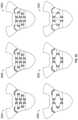
- FIGS. 3 A- 3 Care top-view diagrams illustrating a flattened footwear upper 305 with a lacing architecture 300 for use in footwear assemblies including a motorized lacing engine, according to some example embodiments.
- the upper 305is assumed to be designed for incorporation into a right foot version of a footwear assembly.
- FIG. 3 Ais a top-view diagram of a flattened footwear upper 305 with a lacing architecture 300 as illustrated.
- footwear upper 305includes a series of lace guides 320 A- 320 J (collectively referred to as lace guide(s) 320 ) with a lace cable 310 running through the lace guides 320 .
- the lace cable 310forms a loop that is terminated on each side of the upper 305 at a lateral lace fixation 345 A and a medial lace fixation 345 B (collectively referred to as lace fixation points 345 ) with the middle portion of the loop routed through a lacing engine within a mid-sole of the footwear assembly.
- the upper 305also includes reinforcements associated with each of the series of lace guides 320 .
- the reinforcementscan cover individual lace guides or span multiple lace guides.
- the reinforcementsinclude a central reinforcement 325 , a first lateral reinforcement 335 A, a first medial reinforcement 335 B, a second lateral reinforcement 330 A, a second medial reinforcement 330 B.
- the middle portion of the lace cable 310is routed to and/or from the lacing engine via a lateral rear lace guide 315 A and a medial rear lace guide 315 B, and exits and/or enters the upper 300 through a lateral lace exit 340 A and a medial lace exit 340 B.
- the upper 305can include different portions, such as a forefoot (toe) portion 307 , a mid-foot portion 308 , and a heel portion 309 .
- the forefoot portion 307corresponding with joints connecting metatarsal bones with phalanx bones of a foot.
- the mid-foot point 308may correspond with an arch area of the foot.
- the heel portion 309may correspond with the rear or heel portions of the foot.
- the medial and lateral sides of the mid-foot portion of the upper 305can include a central portion 306 .
- the central portion 306can include an opening spanned by crisscrossing (or similar) pattern of laces that allows for the fit of the footwear upper around the foot to be adjusted.
- a central portion 306 including an openingalso facilitates entry and removal of the foot from the footwear assembly.
- the lace guides 320are tubular or channel structures to retain the lace cable 310 , while routing the lace cable 310 through a pattern along each of a lateral side and a medial side of the upper 305 .
- the lace guides 320are u-shaped plastic tubes laid out in an essentially sinusoidal wave pattern, which cycles up and down along the medial and lateral sides of the upper 305 .
- the number of cycles completed by the lace cable 310may vary depending on shoe size. Smaller sized footwear assemblies may only be able to accommodate one and one half cycles, with the example upper 305 accommodating two and one half cycles before entering the medial rear lace guide 315 B or the lateral rear lace guide 315 A.
- the patternis described as essentially sinusoidal, as in this example at least, the u-shape guides have a wider profile than a true sine wave crest or trough. In other examples, a pattern more closely approximating a true sine wave pattern could be utilized (without extensive use of carefully curved lace guides, a true sine wave is not easily attained with a lace stretched between lace guides).
- the shape of the lace guides 320can be varied to generate different torque versus lace displacement curves, where torque is measured at the lacing engine in the mid-sole of the shoe.
- lace guides with tighter radius curvescan result in a change to the torque versus lace displacement curve.
- the lace cableexperiences higher friction, which can result in a higher initial torque, which may appear to smooth out the torque out over the torque versus lace displacement curve.
- it may be more desirable to maintain a low initial torque levele.g., by keep friction within the lace guides low
- lace guide placement pattern or lace guide designto assist in smoothing the torque versus lace displacement curve.
- lace guidescan be fabricated from plastics, polymers, metal, or fabric.
- layers of fabriccan be used to create a shaped channel to route a lace cable in a desired pattern.
- combinations of plastic or metal guides and fabric overlayscan be used to generate guide components for use in the discussed lacing architectures.
- the reinforcements 325 , 335 , and 330are illustrated associated with different lace guides, such as lace guides 320 .
- the reinforcements 335can include fabric impregnated with a heat activated adhesive that can be adhered over the top of lace guides 320 G, 320 H, a process sometimes referred to as hot melt.
- the reinforcementscan cover a number of lace guides, such as reinforcement 325 , which in this example covers six upper lace guides positioned adjacent to a central portion of the footwear, such as central portion 306 .
- the reinforcement 325could be split down the middle of the central portion 306 to form two pieces covering lace guides along a medial side of the central portion 306 separately from lace guides along a lateral side of the central portion 306 .
- the reinforcement 325could be split into six separate reinforcements covering individual lace guides.
- Use of reinforcementscan vary to change the dynamics of interaction between the lace guides and the underlying footwear upper, such as upper 305 .
- Reinforcementscan also be adhered to the upper 305 in various other manners, including sewing, adhesives, or a combination of mechanisms.
- the manner of adhering the reinforcement in conjunction with the type of fabric or materials used for the reinforcementscan also impact the friction experienced by the lace cable running through the lace guides. For example, a more rigid material hot melted over otherwise flexible lace guides can increase the friction experienced by the lace cable. In contrast, a flexible material adhered over the lace guides may reduce friction by maintaining more of the lace guide flexibility.
- FIG. 3 Aillustrates a central reinforcement 325 that is a single member spanning the medial and lateral upper lace guides ( 320 A, 320 B, 320 E, 320 F, 320 I, and 320 J).
- reinforcement 325is more rigid material with less flexibility than the underlying footwear upper, upper 305 in this example, the resulting central portion 306 of the footwear assembly will exhibit less forgiving fit characteristics. In some applications, a more rigid, less forgiving, central portion 306 may be desirable. However, in applications where more flexibility across the central portion 306 is desired, the central reinforcement 325 can be separated into two or more reinforcements.
- separated central reinforcementscan be coupled across the central portion 306 using a variety of flexible or elastic materials to enable a more form fitting central portion 306 .
- the upper 305can have a small gap running the length of the central portion 306 with one or more elastic members spanning the gap and connecting multiple central reinforcements, such as is at least partially illustrated in FIG. 4 with lace guide 410 and elastic member 440 .
- FIG. 3 Bis another top-view diagram of the flattened footwear upper 305 with a lacing architecture 300 as illustrated.
- footwear upper 305includes a similar lace guide pattern including lace guides 320 with modifications to the configuration of reinforcements 325 , 330 , and 335 .
- the modifications to the reinforcements configurationwill result in at least slightly different fit characteristics and may also change the torque versus lace displacement curve.
- FIG. 3 Cis a series of lacing architecture examples illustrated on flattened footwear uppers according to example embodiments.
- Lace architecture 300 Aillustrates a lace guide pattern similar to the sine wave pattern discussed in reference to FIG. 3 A with individual reinforcements covering each individual lace guide.
- Lace architecture 300 Bonce again illustrates a wave lacing pattern, also referred to as parachute lacing, with elongated reinforcements covering upper lace guide pairs spanning across a central portion and individual lower lace guides.
- Lace architecture 300 Cis yet another wave lacing pattern with a single central reinforcement.
- Lace architecture 300 Dintroduces a triangular shaped lace pattern with individual reinforcements cut to form fit over the individual lace guides.
- Lace architecture 300 Eillustrates a variation in reinforcement configuration in the triangular lace pattern.
- lace architecture 300 Fillustrates another variation in reinforcement configuration including a central reinforcement and consolidated lower reinforcements.
- FIG. 4is a diagram illustrating a portion of a footwear upper 405 with a lacing architecture 400 for use in footwear assemblies including a motorized lacing engine, according to some example embodiments.
- a medial portion of upper 405is illustrated with lace guides 410 routing lace cable 430 through to medial exit guide 435 .
- Lace guides 410are encapsulated in reinforcements 420 to form lace guide components 415 , with at least a portion of the lace guide components being repositionable on upper 405 .
- the lace guide components 415are backed with hook-n-loop material and the upper 405 provides a surface receptive to the hook-n-loop material.
- the lace guide components 415can be backed with the hook portion with the upper 405 providing a knit loop surface to receive the lace guide components 415 .
- lace guide components 415can have a track interface integrated to engage with a track, such as track 445 .
- a track-based integrationcan provide a secure, limited travel, movement option for lace guide components 415 .
- track 445runs essentially perpendicular to the longitudinal axis of the central portion 450 and allows for positioning a lace guide component 415 along the length of the track.
- the track 445can span across from a lateral side to a medial side to hold a lace guide component on either side of central portion 450 . Similar tracks can be positioned in appropriate places to hold all of the lace guide components 415 , enabling adjustment in restrictions directions for all lace guides on footwear upper 405 .
- the footwear upper 405illustrates another example lacing architecture including central elastic members, such as elastic member 440 .
- central elastic memberssuch as elastic member 440 .
- at least the upper lace guide components along the medial and lateral sidescan be connected across the central portion 450 with elastic members that allow for different footwear designs to attain different levels of fit and performance.
- a high performance basketball shoethat needs to secure a foot through a wide range of lateral movement may utilize elastic members with a high modulus of elasticity to ensure a snug fit.
- a running shoemay utilize elastic members with a low modulus of elasticity, as the running shoe may be designed to focus on comfort for long distance road running versus providing high levels of lateral motion containment.
- the elastic members 440can be interchangeable or include a mechanism to allow for adjustment of the level of elasticity.
- the footwear uppersuch as upper 405
- the footwear uppercan include a gap along central portion 450 at least partially separating a medial side from a lateral side. Even with a small gap along central portion 450 elastic members, such as elastic member 440 , can be used to span the gap.
- FIG. 4only illustrates a single track 445 or a single elastic member 440 , these elements can be replicated for any or all of the lace guides in a particular lacing architecture.
- FIG. 5is a diagram illustrating a portion of footwear upper 405 with lacing architecture 400 for use in footwear assemblies including a motorized lacing engine, according to some example embodiments.
- the central portion 450 illustrated in FIG. 4is replaced with a central closure mechanism 460 , which is illustrated in this example as a central zipper 465 .
- the central closure mechanismis designed to enable a wider opening in the footwear upper 405 for easy entry and exit.
- the central zipper 465can be easily unzipped to enable foot entry or exit.
- the central closure 460can be hook and loop, snaps, clasps, toggles, secondary laces, or any similar closure mechanism.
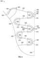
- FIG. 6is a diagram illustrating a portion of footwear upper 405 with a lacing architecture 600 for use in footwear assemblies including a motorized lacing engine, according to some example embodiments.
- lacing architecture 600adds a heel lacing component 615 including a heel lacing guide 610 and a heel reinforcement 620 as well as a heel redirect guide 610 and a heel exit guide 635 .
- the heel redirect guide 610shifts the lace cable 430 from exiting the last lace guide 410 towards a heel lacing component 615 .
- the heel lacing component 615is formed from a heel lacing guide 610 with a heel reinforcement 620 .
- the heel lacing guide 610is depicted with a similar shape to lacing guides used in other locations on upper 405 .
- the heel lacing guide 610can be other shapes or include multiple lace guides.
- the heel lace component 615is shown mounted on a heel track 645 allowing for adjustability of the location of the heel lace component 615 .
- other mechanismscan be utilized to enable adjustment in positioning of the heel lace component 615 , such as hook and loop fasteners or comparable fastening mechanisms.
- the upper 405includes a heel ridge 650 , which like the central portion 450 discussed above can include a closure mechanism.
- the heel closure mechanismis designed to provide easy entry and exit from the footwear by expanding a traditional footwear assembly foot opening.
- the heel lacing component 615can be connected across the heel ridge 650 (with or without a heel closure mechanism) to a matching heel lacing component on the opposite side.
- the connectioncan include an elastic member, similar to elastic member 440 .
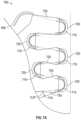
- FIG. 7 A- 7 Bare diagrams illustrating a portion of footwear upper 405 with a lacing architecture 700 for use in footwear assemblies including a motorized lacing engine, according to some example embodiments.
- the lacing architecture 700includes lace guides 710 for routing lace 730 .
- the lace guides 710can include associated reinforcements 720 .
- the lace guides 710are configured to allow for flexing of portions of the lace guides 710 from an open initial position illustrated in FIG. 7 A to a flexed closed position illustrated in FIG. 7 B (with phantom lines illustrating the opposition positions in each figure for reference).
- the lace guides 710include extension portions that exhibit flex of approximately 14 degrees between the open initial position and the closed position.
- lace guide 710can exhibit more or less flex between an initial and final position (or shape) of the lace guide 710 .
- the flexing of the lace guides 710occurs as the lace 730 is tightened.
- the flexing of the lace guides 710works to smooth out the torque versus lace displacement curve by applying some initial tension to the lace 730 and providing an additional mechanism to dissipate lace tension during the tightening process.
- lace guide 710creates some initial tension in the lace cable, which also functions to take up slack in the lace cable.
- the lace guide 710flexes or deforms
- the lace guides 710are plastic or polymer tubes and can have different modulus of elasticity depending upon the particular composition of the tubes.
- the modulus of elasticity of the lace guides 710 along with the configuration of the reinforcements 720will control the amount of additional tension induced in the lace 730 by flexing of the lace guides 710 .
- the elastic deformation of the ends (legs or extensions) of the lace guides 710induces a continued tension on the lace 730 as the lace guides 710 attempt to return to original shape.
- the entire lace guideflexes uniformly over the length of the lace guide.
- the flexoccurs primarily within the u-shaped portion of the lace guide with the extensions remaining substantially straight.
- the extensionsaccommodate most of the flex with the u-shaped portion remaining relatively fixed.
- the reinforcements 720are adhered over the lace guides 710 in a manner that allows for movement of the ends of the lace guides 710 .
- reinforcements 720are adhered through the hot melt process discussed above, with the placement of the heat activated adhesive allowing for an opening to enable flex in the lace guides 710 .
- the reinforcements 720can be sewed into place or use a combination of adhesives and stitching. How the reinforcements 720 are adhered or structured can affect what portion of the lace guide flexes under load from the lace cable.
- the hot meltis concentrated around the u-shaped portion of the lace guide leaving the extensions (legs) more free to flex.
- FIGS. 7 C- 7 Dare diagrams illustrating deformable lace guides 710 for use in footwear assemblies, according to some example embodiments.
- lace guides 710 introduced above in reference to FIGS. 7 A and 7 Bare discussed in additional detail.
- FIG. 7 Cillustrates the lace guide 710 in a first (open) state, which can be considered a non-deformed state.
- FIG. 7 Dillustrates the lace guide 710 in a second (closed/flexed) state, which can be considered a deformed state.
- the lace guide 710can include three different sections, such as a middle section 712 , a first extension 714 , and a second extension 716 .
- the lace guide 710can also include a lace reception opening 740 and a lace exit opening 742 .
- lace guide 710can have different modulus of elasticity, which controls the level of deformation with a certain applied tension.
- the lace guide 710can be constructed with different sections having different modulus of elasticity, such as the middle section 712 having a first modulus of elasticity, the first extension having a second modulus of elasticity and the second extension having a third modulus of elasticity.
- the second and third moduli of elasticitycan be substantially similar, resulting in the first extension and the second extension flexing or deforming in a similar manner.
- substantially similarcan be interpreted as the moduli of elasticity being within a few percentage points of each other.
- the lace guide 710can have a variable modulus of elasticity shifting from a high modulus at the apex 746 to a low modulus towards the outer ends of the first extension and the second extension.
- the moduluscan vary based on wall thickness of the lace guide 710 .
- the lace guide 710defines a number of axes useful is describing how the deformable lace guide functions.
- the first extension 714can define an first incoming lace axis 750 , which aligns with at least an outer portion of an inner channel defined within the first extension 714 .
- the second extension 716defines an first outgoing lace axis 760 , which aligns with at least an outer portion of an inner channel defined within the second extension 716 .
- the lace guide 710defines a second incoming lace axis 752 and a second outgoing lace axis 762 , which are each aligned with respective portions of the first extension and the second extension.
- the lace guide 710also includes a medial axis 744 that intersects the lace guide 710 at the apex 746 and is equidistant from the first extension and the second extension (assuming a symmetrical lace guide in a non-deformed state as illustrated in FIG. 7 C ).
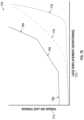
- FIG. 7 Eis a graph 770 illustrating various torque versus lace displacement curves for deformable lace guides, according to some example embodiments.
- one of the benefits achieved using lace guides 710involves modifying torque (or lace tension) versus lace displacement (or shortening) curves.
- Curve 776illustrates a torque versus displacement curve for a non-deformable lace guide used in an example lacing architecture. The curve 776 illustrates how laces experience a rapid increase in tension over a short displacement near the end of the tightening process.
- curve 778illustrates a torque versus displacement curve for a first deformable lace guide used in an example lacing architecture.
- the cure 778begins in a fashion similar to curve 776 , but as the lace guides deform with additional lace tension the curve is flattened, resulting in tension increasing over a larger lace displacement. Flattening out the curves allows for more control of fit and performance of the footwear for the end users.
- the final exampleis split into three segments, an initial tightening segment 780 , an adaptive segment 782 , and a reactive segment 784 .
- the segments 780 , 782 , 784may be utilized in any circumstance where the torque and resultant displacement is desired.
- the reactive segment 784may particularly be utilized in circumstances where the motorized lacing engine makes sudden changes or corrections in the displacement of the lace in reaction to unanticipated external factors, e.g., the wearer has abruptly stopped moving, resulting in a relatively high load on the lace.
- the adaptive segment 782may be utilized when more gradual displacement of the lace may be utilized because a change in the load on the lace may be anticipated, e.g., because the change in load may be less sudden or a change in activity is input into the motorized lacing engine by the wearer or the motorized lacing engine is able to anticipate a change in activity through machine learning.
- the deformable lace guide design resulting in this final exampleis designed to create the adaptive segment 782 and reactive segment 784 through lace guide structural design (such as channel shape, material selection, or a combination parameters).
- the lacing architecture and lace guides producing the final examplealso produce a pre-tension in the lace cable resulting in the illustrated initial tightening segment 780 .
- FIGS. 8 A- 8 Fare diagrams illustrating an example lacing guide 800 for use in certain lacing architectures, according to some example embodiments.
- an alternative lace guide with an open lace channelis illustrated.
- the lacing guide 800 described belowcan be substituted into any of the lacing architectures discussed above in reference to lace guide 410 , heel lace guide 610 , or even the medial exit guide 435 . All of the various configurations discussed above will not be repeated here for the sake of brevity.
- the lacing guide 800includes a guide tab 805 , a stitch opening 810 , a guide superior surface 815 , a lace retainer 820 , a lace channel 825 , a channel radius 830 , a lace access opening 840 , a guide inferior surface 845 , and a guide radius 850 .
- Advantages of an open channel lace guide, such as lacing guide 800include the ability to easily route the lace cable after installation of the lace guides on the footwear upper. With tubular lace guides as illustrated in many of the lace architecture examples discussed above, routing the lace cable through the lace guides is most easily accomplish before adhering the lace guides to the footwear upper (not to say it cannot be accomplished later). Open channel lace guides facilitate simple lace routing by allowing the lace cable to simply be pushed pass the lace retainer 820 after the lace guides 800 are positioned on the footwear upper.
- the lacing guide 800can be fabricated from various materials including metal or plastics.
- the lacing guide 800can be initially attached to a footwear upper through stitching or adhesives.
- the illustrated designincludes a stitch opening 810 that is configured to enable easy manual or automated stitching of lacing guide 800 onto a footwear upper (or similar material).
- lace cablecan be routed by simply pulling a loop of lace cable into the lace channel 825 .
- the lace access opening 840extends through the inferior surface 845 to provide a relief recess for the lace cable to get around the lace retainer 820 .
- the lace retainer 820can be different dimensions or even be split into multiple smaller protrusions.
- the lace retainer 820can be narrower in width, but extend further towards or even into access opening 840 .
- the access opening 840can also be different dimensions, and will usually somewhat mirror the shape of lace retainer 820 (as illustrated in FIG. 8 F ).
- the channel radius 830is designed to correspond to, or be slightly larger then, the diameter of the lace cable.
- the channel radius 830is one of the parameters of the lacing guide 800 that can control the amount of friction experienced by the lace cable running through the lacing guide 800 .
- Another parameter of lacing guide 800 that impacts friction experienced by the lace cableincludes guide radius 850 .
- the guide radius 850also may impact the frequency or spacing of lace guides positioned on a footwear upper.
- FIG. 8 Gis a diagram illustrating a portion of footwear upper 405 with a lacing architecture 890 using lacing guides 800 , according to some example embodiments.
- multiple lacing guides 800are arranged on a lateral side of footwear upper 405 to form half of the lacing architecture 890 .
- lacing architecture 890uses lacing guides 800 to form a wave pattern or parachute lacing pattern to route the lace cable.
- lace tighteningcan produce both later-medial tightening as well as anterior-posterior tightening of the footwear upper 405 .
- lacing guides 800are at least initially adhered to upper 405 through stitching 860 .
- the stitching 860is shown over or engaging stitch opening 810 .
- One of the lacing guide 800is also depicted with a reinforcement 870 covering the lacing guide.
- Such reinforcementscan be positioned individually over each of the lacing guides 800 .
- larger reinforcementscould be used to cover multiple lacing guides.
- reinforcement 870can be adhered through adhesives, heat-activated adhesives, and/or stitching.
- reinforcement 870can be adhered using adhesives (heat-activated or not) and a vacuum bagging process that uniformly compresses the reinforcement over the lacing guide.
- a similar vacuum bagging processcan also be used with reinforcements and lacing guides discussed above.
- mechanical presses or similar machinescan be used to assist with adhering reinforcements over lacing guides.
- the lace cablecan be routed through the lacing guides. Lace cable routing can begin with anchoring a first end of the lace cable at lateral anchor point 470 . The lace cable can then be pulled into each lace channel 825 starting with the anterior most lacing guide and working posteriorly towards the heel of upper 405 . Once the lace cable is routed through all lacing guides 800 , reinforcements 870 can be optionally adhered over each of the lacing guides 800 to secure both the lacing guides and the lace cable.
- FIG. 9is a flowchart illustrating a footwear assembly process 900 for assembly of footwear including a lacing engine, according to some example embodiments.
- the assembly process 900includes operations such as: obtaining footwear upper, lace guides, and lace cable at 910 ; routing lace cable through tubular lace guides at 920 ; anchoring a first end of the lace cable at 930 ; anchoring a second end of lace cable at 940 ; positioning lace guides at 950 ; securing lace guides at 960 ; and integrating upper with footwear assembly at 970 .
- the process 900 described in further detail belowcan include some or all of the process operations described and at least some of the process operations can occur at various locations and/or using different automated tools.
- the process 900begins at 910 by obtaining a footwear upper, a plurality of lace guides, and a lace cable.
- the footwear uppersuch as upper 405
- the lace guides in this exampleinclude tubular plastic lace guides as discussed above, but could also include other types of lace guides.
- the process 900continues with the lace cable being routed (or threaded) through the plurality of lace guides.
- the lace cablecan be routed through the lace guides at a different point in the assembly process 900
- tubular lace guidesrouting the lace through the lace guides prior to assembly onto the footwear upper may be preferable.
- the lace guidescan be pre-threaded onto the lace cable, with process 900 beginning with multiple lace guides already threaded onto the lace obtained during the operation at 910 .
- the process 900continues with a first end of the lace cable being anchored to the footwear upper.
- lace cable 430can be anchored along a lateral edge of upper 405 .
- the lace cablemay be temporary anchored to the upper 405 with a more permanent anchor accomplished during integration of the footwear upper with the remaining footwear assembly.
- the process 900can continue with a second end of the lace cable being anchored to the footwear upper. Like the first end of the lace cable, the second end can be temporarily anchored to the upper. Additionally, the process 900 can optionally delay anchoring of the second end until later in the process or during integration with the footwear assembly.
- the process 900continues with the plurality of lace guides being positioned on the upper.
- lace guides 410can be positioned on upper 405 to generate the desired lacing pattern.
- the process 900can continue at 960 by securing the lace guides onto the footwear upper.
- the reinforcements 420can be secured over lace guides 410 to hold them in position.
- the process 900can complete at 970 with the footwear upper being integrated into the remainder of the footwear assembly, including the sole.
- integrationcan include positioning the loop of lace cable connecting the lateral and medial sides of the footwear upper in position to engage a lacing engine in a mid-sole of the footwear assembly.
- FIG. 10is a flowchart illustrating a footwear assembly process 1000 for assembly of footwear including a plurality of lacing guides, according to some example embodiments.
- the assembly process 1000includes operations such as: obtaining footwear upper, lace guides, and lace cable at 1010 ; securing lacing guides on footwear upper at 1020 ; anchoring a first end of the lace cable at 1030 ; routing lace cable through the lace guides at 1040 ; anchoring a second end of lace cable at 1050 ; optionally securing reinforcements over the lace guides at 1060 ; and integrating upper with footwear assembly at 1070 .
- the process 1000 described in further detail belowcan include some or all of the process operations described and at least some of the process operations can occur at various locations and/or using different automated tools.
- the process 1000begins at 1010 by obtaining a footwear upper, a plurality of lace guides, and a lace cable.
- the footwear uppersuch as upper 405
- the footwear uppercan be a flattened footwear upper separated from the remainder of a footwear assembly (e.g., sole, mid-sole, outer cover, etc . . . ).
- the lace guides in this exampleinclude open channel plastic lacing guides as discussed above, but could also include other types of lace guides.
- the process 1000continues with the lacing guides being secured to the upper.
- lacing guides 800can be individually stitched in position on upper 405 .
- the process 1000continues with a first end of the lace cable being anchored to the footwear upper.
- lace cable 430can be anchored along a lateral edge of upper 405 .
- the lace cablemay be temporary anchored to the upper 405 with a more permanent anchor accomplished during integration of the footwear upper with the remaining footwear assembly.
- the process 1000continues with the lace cable being routed through the open channel lace guides, which includes leaving a lace loop for engagement with a lacing engine between the lateral and medial sides of the footwear upper.
- the lace loopcan be a predetermined length to ensure the lacing engine is able to properly tighten the assembled footwear.
- the process 1000can continue with a second end of the lace cable being anchored to the footwear upper. Like the first end of the lace cable, the second end can be temporarily anchored to the upper. Additionally, the process 1000 can optionally delay anchoring of the second end until later in the process or during integration with the footwear assembly. In certain examples, delaying anchoring of the first and/or second end of the lace cable can allow for adjustment in overall lace length, which may be useful during integration of the lacing engine.
- the process 1000can optionally include an operation for securing fabric reinforcements (covers) over the lace guides to further secure them to the footwear upper.
- lacing guides 800can have reinforcements 870 hot melted over the lacing guides to further secure the lacing guides and the lace cable.
- the process 1000can complete at 1070 with the footwear upper being integrated into the remainder of the footwear assembly, including the sole.
- integrationcan include positioning the loop of lace cable connecting the lateral and medial sides of the footwear upper in position to engage a lacing engine in a mid-sole of the footwear assembly.
- the present inventorshave recognized, among other things, a need for an improved lacing architecture for automated and semi-automated tightening of shoe laces.
- This documentdescribes, among other things, example lacing architectures, example lace guides used in the lacing architectures, and related assembly techniques for automated footwear platforms.
- the following examplesprovide a non-limiting examples of the actuator and footwear assembly discussed herein.
- Example 1describes subject matter including a lace guide.
- the lace guideis deformable to assist in facilitating automated lace tightening.
- the lace guidecan include a middle section, a first extension and a second extension.
- the middle sectioncan include an internal channel curved at a first radius and dimensioned to receive a lace cable.
- the first extensioncan extend from a first end of the middle section defining a first incoming lace axis along at least a portion of the internal channel extending through the first extension.
- the first extensioncan be configured to receive the lace cable through a lace reception opening opposite the first end of the middle section.
- the second extensioncan extend from a second end of the middle section defining a first outgoing lace axis along at least a portion of the internal channel extending through the second extension.
- the second extensioncan be configured to receive the lace cable from the middle section and route the lace cable through a lace exit opening along the first outgoing lace axis.
- the lace guidecan be configured to define a first route for a lace cable, the first route including receiving the lace cable along the first incoming lace axis and expelling the lace cable along the first outgoing lace axis.
- the lace guidecan also deflect, in response to tension on the lace cable, resulting in defining a second route for the lace cable, the second route including receiving the lace cable along a second incoming lace axis and expelling the lace cable along a second outgoing lace axis.
- example 2the subject matter of example 1 can optionally include the lace guide inducing a pre-tension in the lace cable by defining the first route.
- any one of examples 1 and 2can optionally include the lace guide having a medial axis intersecting an apex of the middle section and aligned between the first incoming lace axis and the first outgoing lace axis.
- tension on the lace cablecan generate a resultant force vector aligned with the medial axis, resulting in deflection of the lace guide that is symmetric about the medial axis.
- any one of examples 1 and 2can optionally include the lace guide having a medial axis intersecting an apex of the middle section and being aligned between the first incoming lace axis and the first outgoing lace axis.
- tension on the lace cable causing deflection in the lace guidecan generate a resultant force vector that is not aligned with the medial axis, resulting in deflection of the lace guide that is not symmetric about the medial axis.
- any one of examples 1 to 4can optionally include the internal channel being a tubular structure defining a cylindrical cross-section extending through at least the middle section.
- example 6the subject matter of example 5 can optionally include the first extension and the second extension both extending the tubular structure of the internal channel.
- any one of examples 1 to 6can optionally include the middle section having a first modulus of elasticity, the first extension having a second modulus of elasticity, and the second extension having a third modulus of elasticity.
- example 8the subject matter of example 7 can optionally include the second modulus of elasticity being substantially the same as the third modulus of elasticity resulting in the first extension and the second extension flexing substantially the same amount in response to tension on the lace cable being aligned with a medial axis of the lace guide.
- any one of examples 1 to 8can optionally include the internal channel being an open channel structure defining a u-shaped cross-section extending through at least the middle section.
- example 10the subject matter of example 9 can optionally include the first extension and the second extension both extending the open channel structure of the internal channel.
- example 11the subject matter of example 10 can optionally include the lace cable being loaded into the lace guide through the open channel structure of the internal channel.
- Example 12describes subject matter including a footwear assembly including a plurality of deformable lace guides.
- the footwear assemblycan include a footwear upper, a lace cable, and a plurality of deformable lace guides.
- the footwear uppercan include a toe box portion, a medial side, a lateral side, and a heel portion, where the medial side and the lateral side each extend proximally from the toe box portion to the heel portion.
- the lace cablecan include a first end anchored along a distal outside portion of the medial side and a second end anchored along a distal outside portion of the lateral side.
- the plurality of deformable lace guidescan be distributed along the medial side and the lateral side.
- Each deformable lace guide of the plurality of deformable lace guidescan be adapted to receive a length of the lace cable.
- Each deformable lace guidecan form a first shape in response to a first tension on the lace cable and a second shape in response to a second tension on the lace cable.
- each deformable lace guidecan operate to contribute to the first tension in the first shape.
- example 13the subject matter of example 12 can optionally include the second tension being greater than the first tension and the change in tension being generated by a shortening of an overall length of the lace cable.
- the shortening of the overall length of the lace cablecan be performed by a motorized lacing engine within the footwear assembly.
- example 14the subject matter of example 13 can optionally include deformation from the first shape to the second shape of each deformable lace guide of the plurality of deformable lace guides operates to flatten out a cable tension versus shortening length curve.
- each deformable lace guidebeing a tubular structure having a cylindrical cross-section.
- each deformable lace guide of the plurality of deformable lace guidesbeing a U-shaped lace guide including a curved middle section, a first extension extending from a first end of the middle section, and a second extension extending from a second end of the middle section.
- example 17the subject matter of example 16 can optionally include the first extension, the middle section, and second extension all deforming substantially uniformly in response to a change in tension from the first tension to the second tension.
- the first extension, middle section, and second extensionall have a similar modulus of elasticity.
- example 18the subject matter of example 16 can optionally include the first extension and the second extension deforming substantially uniformly in response to a change in tension from the first tension to the second tension.
- the first extension and the second extensionhave a similar modulus of elasticity.
- example 19the subject matter of example 18 can optionally include the middle section exhibiting negligible deformation between the first shape and the second shape in response to the change in tension.
- any one of examples 12 to 19can optionally include a first deformable lace guide of the plurality of deformable lace guides having a first modulus of elasticity resulting in formation of the first shape in response to the first tension and the second shape in response to the second tension.
- a second deformable lace guide of the plurality of deformable lace guidescan have a second modulus of elasticity resulting in formation of a third shape in response to the first tension and a fourth shape in response to the second tension.
- inventive subject matterhas been described with reference to specific example embodiments, various modifications and changes may be made to these embodiments without departing from the broader scope of embodiments of the present disclosure.
- inventive subject mattermay be referred to herein, individually or collectively, by the term “invention” merely for convenience and without intending to voluntarily limit the scope of this application to any single disclosure or inventive concept if more than one is, in fact, disclosed.
- the term “or”may be construed in either an inclusive or exclusive sense. Moreover, plural instances may be provided for resources, operations, or structures described herein as a single instance. Additionally, boundaries between various resources, operations, modules, engines, and data stores are somewhat arbitrary, and particular operations are illustrated in a context of specific illustrative configurations. Other allocations of functionality are envisioned and may fall within a scope of various embodiments of the present disclosure. In general, structures and functionality presented as separate resources in the example configurations may be implemented as a combined structure or resource. Similarly, structures and functionality presented as a single resource may be implemented as separate resources. These and other variations, modifications, additions, and improvements fall within a scope of embodiments of the present disclosure as represented by the appended claims. The specification and drawings are, accordingly, to be regarded in an illustrative rather than a restrictive sense.
- the terms “a” or “an”are used, as is common in patent documents, to include one or more than one, independent of any other instances or usages of “at least one” or “one or more.”
- the term “or”is used to refer to a nonexclusive or, such that “A or B” includes “A but not B,” “B but not A,” and “A and B,” unless otherwise indicated.
- Method (process) examples described hereincan include machine or robotic implementations at least in part.
Landscapes
- Engineering & Computer Science (AREA)
- Microelectronics & Electronic Packaging (AREA)
- Footwear And Its Accessory, Manufacturing Method And Apparatuses (AREA)
Abstract
Description
Claims (20)
Priority Applications (1)
| Application Number | Priority Date | Filing Date | Title |
|---|---|---|---|
| US17/952,512US12329244B2 (en) | 2016-10-26 | 2022-09-26 | Deformable lace guides for automated footwear platform |
Applications Claiming Priority (5)
| Application Number | Priority Date | Filing Date | Title |
|---|---|---|---|
| US201662413142P | 2016-10-26 | 2016-10-26 | |
| US201662424301P | 2016-11-18 | 2016-11-18 | |
| US15/458,824US20180110294A1 (en) | 2016-10-26 | 2017-03-14 | Deformable lace guides for automated footwear platform |
| US16/819,893US11452339B2 (en) | 2016-10-26 | 2020-03-16 | Deformable lace guides for automated footwear platform |
| US17/952,512US12329244B2 (en) | 2016-10-26 | 2022-09-26 | Deformable lace guides for automated footwear platform |
Related Parent Applications (1)
| Application Number | Title | Priority Date | Filing Date |
|---|---|---|---|
| US16/819,893DivisionUS11452339B2 (en) | 2016-10-26 | 2020-03-16 | Deformable lace guides for automated footwear platform |
Publications (2)
| Publication Number | Publication Date |
|---|---|
| US20230020593A1 US20230020593A1 (en) | 2023-01-19 |
| US12329244B2true US12329244B2 (en) | 2025-06-17 |
Family
ID=61971388
Family Applications (3)
| Application Number | Title | Priority Date | Filing Date |
|---|---|---|---|
| US15/458,824AbandonedUS20180110294A1 (en) | 2016-10-26 | 2017-03-14 | Deformable lace guides for automated footwear platform |
| US16/819,893Active2037-09-06US11452339B2 (en) | 2016-10-26 | 2020-03-16 | Deformable lace guides for automated footwear platform |
| US17/952,512ActiveUS12329244B2 (en) | 2016-10-26 | 2022-09-26 | Deformable lace guides for automated footwear platform |
Family Applications Before (2)
| Application Number | Title | Priority Date | Filing Date |
|---|---|---|---|
| US15/458,824AbandonedUS20180110294A1 (en) | 2016-10-26 | 2017-03-14 | Deformable lace guides for automated footwear platform |
| US16/819,893Active2037-09-06US11452339B2 (en) | 2016-10-26 | 2020-03-16 | Deformable lace guides for automated footwear platform |
Country Status (6)
| Country | Link |
|---|---|
| US (3) | US20180110294A1 (en) |
| EP (2) | EP4212057B1 (en) |
| JP (2) | JP7027416B2 (en) |
| KR (2) | KR102613294B1 (en) |
| CN (2) | CN110113962B (en) |
| WO (1) | WO2018080581A1 (en) |
Families Citing this family (28)
| Publication number | Priority date | Publication date | Assignee | Title |
|---|---|---|---|---|
| US10852069B2 (en) | 2010-05-04 | 2020-12-01 | Fractal Heatsink Technologies, LLC | System and method for maintaining efficiency of a fractal heat sink |
| US11185130B2 (en) | 2015-10-07 | 2021-11-30 | Puma SE | Article of footwear having an automatic lacing system |
| US11103030B2 (en) | 2015-10-07 | 2021-08-31 | Puma SE | Article of footwear having an automatic lacing system |
| US11033079B2 (en) | 2015-10-07 | 2021-06-15 | Puma SE | Article of footwear having an automatic lacing system |
| US10307108B2 (en) | 2015-10-13 | 2019-06-04 | Elekta, Inc. | Pseudo-CT generation from MR data using a feature regression model |
| MX378226B (en) | 2015-12-02 | 2025-03-10 | Puma SE | PROCEDURE FOR TYING A SHOE, PARTICULARLY A SPORTS SHOE |
| ITUB20160158A1 (en)* | 2016-01-15 | 2017-07-15 | Scarpa Calzaturificio Spa | SKI BOOT |
| EP3531857B1 (en) | 2016-10-26 | 2022-08-17 | NIKE Innovate C.V. | Lacing architecture for automated footwear platform |
| CN110113962B (en) | 2016-10-26 | 2022-06-07 | 耐克创新有限合伙公司 | Deformable Lace Guide for Automated Footwear Platforms |
| US11083248B2 (en) | 2016-10-26 | 2021-08-10 | Nike, Inc. | Automated footwear platform having upper elastic tensioner |
| US11071353B2 (en) | 2016-10-26 | 2021-07-27 | Nike, Inc. | Automated footwear platform having lace cable tensioner |
| US11439192B2 (en) | 2016-11-22 | 2022-09-13 | Puma SE | Method for putting on or taking off a piece of clothing or for closing, putting on, opening, or taking off a piece of luggage |
| MX2019005959A (en) | 2016-11-22 | 2019-07-10 | Puma SE | Method for fastening a shoe, in particular a sports shoe, and shoe, in particular sports shoe. |
| WO2019001676A1 (en)* | 2017-06-27 | 2019-01-03 | Puma SE | Shoe, especially sports shoe |
| EP3697251B1 (en) | 2017-10-20 | 2022-08-03 | Nike Innovate C.V. | Lacing architecture for automated footwear platform |
| CN113397265B (en)* | 2017-10-25 | 2023-08-29 | 耐克创新有限合伙公司 | Automatic footwear system with preset user profile |
| US11684110B2 (en)* | 2018-08-31 | 2023-06-27 | Nike, Inc. | Autolacing footwear |
| USD889805S1 (en) | 2019-01-30 | 2020-07-14 | Puma SE | Shoe |
| USD899053S1 (en) | 2019-01-30 | 2020-10-20 | Puma SE | Shoe |
| USD906657S1 (en) | 2019-01-30 | 2021-01-05 | Puma SE | Shoe tensioning device |
| JP7498194B2 (en)* | 2019-04-23 | 2024-06-11 | プーマ エス イー | Footwear |
| EP4013297A4 (en) | 2019-08-16 | 2023-12-13 | Poltorak Technologies, LLC | DEVICE AND METHOD FOR MEDICAL DIAGNOSTICS |
| US11484089B2 (en) | 2019-10-21 | 2022-11-01 | Puma SE | Article of footwear having an automatic lacing system with integrated sound damping |
| EP4157025A1 (en)* | 2020-05-31 | 2023-04-05 | Nike Innovate C.V. | Upper for an article of footwear |
| IT202100014261A1 (en)* | 2021-05-31 | 2022-12-01 | Alpinestars Res Spa | Footwear with retention system |
| US12171306B2 (en) | 2021-11-16 | 2024-12-24 | Puma SE | Article of footwear having an automatic lacing system |
| US11877624B2 (en) | 2021-11-18 | 2024-01-23 | Shimano Inc. | Shoelace arrangement and shoelace guide for shoe |
| USD1054193S1 (en) | 2022-11-02 | 2024-12-17 | Zappos IP LLC | Footwear |
Citations (114)
| Publication number | Priority date | Publication date | Assignee | Title |
|---|---|---|---|---|
| FR335680A (en) | 1903-10-05 | 1904-02-05 | Fortune Delany | Automatic shoe |
| FR616991A (en) | 1926-06-02 | 1927-02-11 | Shoe lacing mode | |
| US2102265A (en) | 1937-02-25 | 1937-12-14 | Halberstadt Bert | Overshoe and the like |
| JPS4841446U (en) | 1971-09-13 | 1973-05-26 | ||
| JPS5188441U (en) | 1975-01-08 | 1976-07-15 | ||
| US4142307A (en) | 1977-01-07 | 1979-03-06 | Hans Martin | Ski and skating boot |
| US4756098A (en) | 1987-01-21 | 1988-07-12 | Gencorp Inc. | Athletic shoe |
| US4924605A (en) | 1985-05-22 | 1990-05-15 | Spademan Richard George | Shoe dynamic fitting and shock absorbtion system |
| US4969277A (en) | 1986-11-28 | 1990-11-13 | Williams Paul H | Adjustable shoe |
| US4972613A (en) | 1989-10-10 | 1990-11-27 | Wolverine World Wide, Inc. | Rear entry athletic shoe |
| CN1047797A (en) | 1989-06-03 | 1990-12-19 | 普玛股份有限公司 | The footwear of the flexible upper material of closing device are housed |
| US5176624A (en) | 1990-07-21 | 1993-01-05 | Kuehnreich Heinz Peter | Shoe bandage |
| JPH054902U (en) | 1991-07-05 | 1993-01-26 | 岡本 正三 | Variable size shoes |
| US5293675A (en) | 1992-12-28 | 1994-03-15 | Moti Shai | Fastener for shoelaces and the like |
| WO1994010869A1 (en) | 1992-11-06 | 1994-05-26 | Salomon S.A. | Shoe with flexible tightening bond |
| US5371957A (en) | 1993-12-14 | 1994-12-13 | Adidas America, Inc. | Athletic shoe |
| JPH07208A (en) | 1991-12-20 | 1995-01-06 | Kobatsuku:Kk | Shoelace tightener |
| JPH0751103A (en) | 1993-06-21 | 1995-02-28 | Salomon Sa | Sports shoes |
| US5425185A (en) | 1993-05-28 | 1995-06-20 | Tretorn Ab | Shoe with a side mounted central rotary closure |
| US5463822A (en) | 1993-05-28 | 1995-11-07 | Puma Ag | Shoe with a central rotary closure and self-aligning coupling elements |
| US5467537A (en) | 1994-03-18 | 1995-11-21 | Nike, Inc. | Shoe with adjustable closure system |
| US5555650A (en) | 1994-05-27 | 1996-09-17 | Longbottom; Mark A. | Laceless athletic shoe |
| US5692319A (en) | 1995-06-07 | 1997-12-02 | Nike, Inc. | Article of footwear with 360° wrap fit closure system |
| CN1172621A (en) | 1997-07-08 | 1998-02-11 | 周龙交 | Self-lacing, detachable and removable shoes |
| US5755044A (en) | 1996-01-04 | 1998-05-26 | Veylupek; Robert J. | Shoe lacing system |
| CN1196209A (en) | 1996-12-17 | 1998-10-21 | 萨洛蒙公司 | Sems |
| US5845416A (en) | 1996-05-02 | 1998-12-08 | Hands; Rhonda B. | Transparent shoe cover |
| US5909947A (en) | 1996-01-22 | 1999-06-08 | Salomon S.A. | Sport footwear assembly |
| JP2000014410A (en) | 1998-06-30 | 2000-01-18 | Ryuko Shu | Shoes having automatically string tightening and untightening functions |
| US6032387A (en) | 1998-03-26 | 2000-03-07 | Johnson; Gregory G. | Automated tightening and loosening shoe |
| JP3135943B2 (en) | 1990-10-11 | 2001-02-19 | 株式会社コーセー | Whitening agent |
| US6289558B1 (en) | 1997-08-22 | 2001-09-18 | Boa Technology, Inc. | Footwear lacing system |
| US6324774B1 (en) | 2000-02-15 | 2001-12-04 | Charles W. Zebe, Jr. | Shoelace retaining clip and footwear closure means using same |
| US6444908B1 (en) | 2000-06-27 | 2002-09-03 | Koninklijke Philips Electronics, N.V. | Apparatus having a cable grommet of uniform flexibility |
| US6502329B1 (en) | 1999-11-04 | 2003-01-07 | Howard Silagy | Footwear article using a criss-crossing lacing pattern |
| FR2827486A1 (en) | 2001-07-20 | 2003-01-24 | Salomon Sa | Sports shoe is fastened by lace fixed at one end to one side of upper, passed around tag on opposite side of upper and back through second tag on first |
| US20030204938A1 (en) | 1997-08-22 | 2003-11-06 | Hammerslag Gary R. | Footwear lacing system |
| US6691433B2 (en) | 2002-02-08 | 2004-02-17 | Kun-Chung Liu | Automated tightening shoe |
| US6735829B2 (en) | 2001-10-15 | 2004-05-18 | Taiwan Industrial Fastener Corporation | U-shaped lace buckle |
| JP2004167144A (en) | 2002-11-22 | 2004-06-17 | Midori Okabayashi | Footwear |
| US6896128B1 (en) | 1998-03-26 | 2005-05-24 | Gregory G. Johnson | Automated tightening shoe |
| US20050126043A1 (en)* | 2003-12-10 | 2005-06-16 | The Burton Corporation | Lace system for footwear |
| US6922917B2 (en) | 2003-07-30 | 2005-08-02 | Dashamerica, Inc. | Shoe tightening system |
| JP2005205162A (en) | 2003-12-22 | 2005-08-04 | Chest M I Inc | Safety shoes for walking |
| US20050198867A1 (en) | 2004-03-12 | 2005-09-15 | Frederick Labbe | Self tying shoe |
| CN1694630A (en) | 1998-03-26 | 2005-11-09 | 格里高利·G·约翰逊 | Automatic tightening shoes |
| US20060075614A1 (en) | 2004-10-12 | 2006-04-13 | Chmelar Erik V | Shoelace protector |
| US7073279B2 (en) | 2004-07-12 | 2006-07-11 | Duck Gi Min | Shoelace tightening structure |
| US7082701B2 (en) | 2004-01-23 | 2006-08-01 | Vans, Inc. | Footwear variable tension lacing systems |
| US20060174516A1 (en) | 2005-02-04 | 2006-08-10 | Salomon S.A. | Sports boot |
| US7096559B2 (en) | 1998-03-26 | 2006-08-29 | Johnson Gregory G | Automated tightening shoe and method |
| JP2007000208A (en) | 2005-06-21 | 2007-01-11 | Nhk Spring Co Ltd | Seat trim cover and manufacturing method thereof |
| US20070068040A1 (en) | 2005-09-28 | 2007-03-29 | Salomon S.A., Of Metz-Tessy, France | Footwear with improved tightening of the upper |
| US20070169378A1 (en) | 2006-01-06 | 2007-07-26 | Mark Sodeberg | Rough and fine adjustment closure system |
| JP2008525052A (en) | 2004-10-29 | 2008-07-17 | ボア テクノロジイ インコーポレイテッド | Opening and closing system based on reel |
| US20080172848A1 (en) | 2007-01-18 | 2008-07-24 | Chin-Chu Chen | Shoelace fastening assembly |
| US20080307673A1 (en) | 2007-06-14 | 2008-12-18 | Johnson Gregory G | Automated tightening shoe |
| US7752774B2 (en) | 2007-06-05 | 2010-07-13 | Tim James Ussher | Powered shoe tightening with lace cord guiding system |
| US20100175278A1 (en) | 2007-01-17 | 2010-07-15 | Deeluxe Sportartikel Handels Gmbh | Boot in particular ski or snowboard boot |
| WO2011004422A1 (en) | 2009-07-06 | 2011-01-13 | 株式会社アシックス | Shoe with shoelace fastener fitting structure |
| US20110113648A1 (en) | 2008-06-27 | 2011-05-19 | Salomon S.A.S. | Footwear which improves foot support |
| JP2011519611A (en) | 2008-05-02 | 2011-07-14 | ナイキ インターナショナル リミテッド | Automatic shoelace system |
| WO2011091325A1 (en) | 2010-01-21 | 2011-07-28 | Boa Technology, Inc. | Guides for lacing systems |
| US20120000091A1 (en) | 2010-07-01 | 2012-01-05 | Boa Technology, Inc. | Lace guide |
| US20120011744A1 (en) | 2010-07-19 | 2012-01-19 | Nike, Inc. | Decoupled Foot Stabilizer System |
| JP2012045376A (en) | 2010-07-30 | 2012-03-08 | Achilles Corp | Waterproof shoe |
| US20120117821A1 (en) | 2010-11-10 | 2012-05-17 | Adams Thomas M | Single Pull and Double Pull Fit Adjustment Systems for Shoes |
| US20120240428A1 (en) | 2011-03-23 | 2012-09-27 | Powerslide Sportartikelvertriebs Gmbh | Sports shoe |
| US20130086816A1 (en) | 2011-08-18 | 2013-04-11 | Palidium, Inc. | Automated tightening shoe |
| CN103462737A (en) | 2006-09-12 | 2013-12-25 | Boa科技股份有限公司 | Closure system for braces, protective wear and similar articles |
| US20140079900A1 (en) | 2012-09-18 | 2014-03-20 | John Ramirez | Attachable grip enhancers and sports tapes for the human body |
| US20140082963A1 (en) | 2012-08-31 | 2014-03-27 | Nike, Inc. | Footwear Having Removable Motorized Adjustment System |
| US20140094728A1 (en) | 2012-08-31 | 2014-04-03 | Boa Technology Inc. | Motorized tensioning system for medical braces and devices |
| US20140123449A1 (en) | 2012-11-06 | 2014-05-08 | Boa Technology Inc. | Devices and methods for adjusting the fit of footwear |
| US8752200B2 (en) | 2011-07-12 | 2014-06-10 | At&T Intellectual Property I, L.P. | Devices, systems and methods for security using magnetic field based identification |
| US20140157627A1 (en) | 2012-12-07 | 2014-06-12 | Nike, Inc. | Article Of Footwear With Adjustable Stiffness |
| US20140173939A1 (en) | 2009-04-16 | 2014-06-26 | Nike, Inc. | Article of Footwear for Snowboarding |
| US8800173B2 (en) | 2011-08-23 | 2014-08-12 | Nicholas Smith | Shoelace protector and methods thereof |
| US20140290016A1 (en)* | 2013-04-01 | 2014-10-02 | Boa Technology Inc. | Methods and devices for retrofitting footwear to include a reel based closure system |
| US20140360049A1 (en) | 2013-06-10 | 2014-12-11 | Nike, Inc. | Article With Adjustable Rearward Covering Portion |
| US20150013184A1 (en) | 2013-07-11 | 2015-01-15 | Nike, Inc. | Article With Closed Instep Portion Having Variable Volume |
| US20150026937A1 (en) | 2012-03-16 | 2015-01-29 | Asics Corporation | Lace Fitting Structure |
| US20150033519A1 (en)* | 1997-08-22 | 2015-02-05 | Boa Technology, Inc. | Reel based closure system |
| US20150040429A1 (en) | 2013-07-11 | 2015-02-12 | Nike, Inc. | Article With Tensioning System Including Driven Tensioning Members |
| US20150047230A1 (en) | 2013-07-11 | 2015-02-19 | Nike, Inc. | Article With Tensioning System Including Tension Balancing Member |
| US20150059206A1 (en)* | 2013-09-05 | 2015-03-05 | Boa Technology, Inc. | Guides and components for closure systems and methods therefor |
| US8973289B2 (en) | 2011-01-06 | 2015-03-10 | Nike, Inc. | Lacing closure system for an object |
| US20150096202A1 (en)* | 2013-09-13 | 2015-04-09 | K-2 Corporation | Sports boot with articulating lace guide |
| US20150150705A1 (en)* | 2013-11-18 | 2015-06-04 | Boa Technology, Inc. | Methods and devices for providing automatic closure of prosthetics and orthotics |
| US20150289595A1 (en)* | 2014-04-15 | 2015-10-15 | Nike, Inc. | Footwear Having Motorized Adjustment System and Elastic Upper |
| JP2016507296A (en) | 2013-01-17 | 2016-03-10 | ナイキ イノベイト セー. フェー. | Easy access footwear products |
| CN105517459A (en) | 2013-09-03 | 2016-04-20 | 新景株式会社 | Wire tightening device and providing method therefor |
| KR200480235Y1 (en) | 2015-09-16 | 2016-04-27 | 소윤서 | Detachable lacing system for footwear |
| US20160143396A1 (en) | 2008-05-02 | 2016-05-26 | Nike, Inc. | Lacing System With Guide Elements |
| US20160198803A1 (en) | 2008-11-21 | 2016-07-14 | Boa Technology, Inc. | Reel based lacing system |
| US20160198799A1 (en) | 2015-01-08 | 2016-07-14 | Erin Partin | Removable decorative cover for an elevated heel shoe |
| WO2016184899A1 (en) | 2015-05-20 | 2016-11-24 | On Clouds Gmbh | Running shoe having lacing |
| FR3038815A1 (en) | 2015-07-17 | 2017-01-20 | Digit Solutions | AUTOMATIC LACING SHOE |
| US20170099909A1 (en) | 2015-10-09 | 2017-04-13 | Adidas Ag | Laceless shoe |
| US9763495B2 (en) | 2014-04-11 | 2017-09-19 | Asics Corporation | Upper of shoe |
| US20170265581A1 (en) | 2016-03-15 | 2017-09-21 | Nike, Inc. | Actuator for an automated footwear platform |
| US20170265585A1 (en) | 2016-03-15 | 2017-09-21 | Nike, Inc. | Transmission for motorized tensioning system of article of footwear |
| EP3254578A1 (en) | 2016-06-08 | 2017-12-13 | Salomon S.A.S. | Shoe and use of such a shoe |
| WO2018026957A1 (en) | 2016-08-02 | 2018-02-08 | Boa Technology Inc. | Tension member guides of a lacing system |
| US20180110294A1 (en) | 2016-10-26 | 2018-04-26 | Nike, Inc. | Deformable lace guides for automated footwear platform |
| US20180199671A1 (en) | 2016-10-26 | 2018-07-19 | Summer L. Schneider | Automated footwear platform having lace cable tensioner |
| US20180199673A1 (en) | 2016-10-26 | 2018-07-19 | Summer L. Schneider | Automated footwear platform having upper elastic tensioner |
| WO2018170116A1 (en) | 2017-03-15 | 2018-09-20 | Schneider Summer L | Automated footwear having cable and upper tensioners |
| US20180289110A1 (en) | 2015-10-07 | 2018-10-11 | Puma SE | Shoe, in particular athletic shoe |
| US20180368526A1 (en) | 2015-12-02 | 2018-12-27 | Puma SE | Method for lacing a shoe, particularly a sports shoe |
| KR20210009988A (en) | 2019-07-18 | 2021-01-27 | 엘지전자 주식회사 | Light emitting device for promoting hair growth and controlling method thereof |
| JP7000208B2 (en) | 2018-03-08 | 2022-01-19 | 株式会社奥村組 | Tail clearance measuring device |
| JP2022022011A (en) | 2020-07-23 | 2022-02-03 | 株式会社三洋物産 | Game machine |
| JP7051103B2 (en) | 2018-10-30 | 2022-04-11 | 株式会社ニューギン | Pachinko machine |
- 2017
- 2017-03-14CNCN201780079469.0Apatent/CN110113962B/enactiveActive
- 2017-03-14CNCN202210558715.3Apatent/CN114983094B/enactiveActive
- 2017-03-14EPEP23159916.8Apatent/EP4212057B1/enactiveActive
- 2017-03-14JPJP2019522651Apatent/JP7027416B2/enactiveActive
- 2017-03-14KRKR1020227025849Apatent/KR102613294B1/enactiveActive
- 2017-03-14WOPCT/US2017/022343patent/WO2018080581A1/ennot_activeCeased
- 2017-03-14KRKR1020197014539Apatent/KR102426894B1/enactiveActive
- 2017-03-14EPEP17865224.4Apatent/EP3531858B1/enactiveActive
- 2017-03-14USUS15/458,824patent/US20180110294A1/ennot_activeAbandoned
- 2020
- 2020-03-16USUS16/819,893patent/US11452339B2/enactiveActive
- 2022
- 2022-02-16JPJP2022022011Apatent/JP7288992B2/enactiveActive
- 2022-09-26USUS17/952,512patent/US12329244B2/enactiveActive
Patent Citations (173)
| Publication number | Priority date | Publication date | Assignee | Title |
|---|---|---|---|---|
| FR335680A (en) | 1903-10-05 | 1904-02-05 | Fortune Delany | Automatic shoe |
| FR616991A (en) | 1926-06-02 | 1927-02-11 | Shoe lacing mode | |
| US2102265A (en) | 1937-02-25 | 1937-12-14 | Halberstadt Bert | Overshoe and the like |
| JPS4841446U (en) | 1971-09-13 | 1973-05-26 | ||
| JPS5188441U (en) | 1975-01-08 | 1976-07-15 | ||
| US4142307A (en) | 1977-01-07 | 1979-03-06 | Hans Martin | Ski and skating boot |
| US4924605A (en) | 1985-05-22 | 1990-05-15 | Spademan Richard George | Shoe dynamic fitting and shock absorbtion system |
| US4969277A (en) | 1986-11-28 | 1990-11-13 | Williams Paul H | Adjustable shoe |
| US4756098A (en) | 1987-01-21 | 1988-07-12 | Gencorp Inc. | Athletic shoe |
| CN1047797A (en) | 1989-06-03 | 1990-12-19 | 普玛股份有限公司 | The footwear of the flexible upper material of closing device are housed |
| US4972613A (en) | 1989-10-10 | 1990-11-27 | Wolverine World Wide, Inc. | Rear entry athletic shoe |
| US5176624A (en) | 1990-07-21 | 1993-01-05 | Kuehnreich Heinz Peter | Shoe bandage |
| JP3135943B2 (en) | 1990-10-11 | 2001-02-19 | 株式会社コーセー | Whitening agent |
| JPH054902U (en) | 1991-07-05 | 1993-01-26 | 岡本 正三 | Variable size shoes |
| JPH07208A (en) | 1991-12-20 | 1995-01-06 | Kobatsuku:Kk | Shoelace tightener |
| JPH08503148A (en) | 1992-11-06 | 1996-04-09 | サロモン エス.エー. | Shoes that are tightened with a flexible cord member |
| WO1994010869A1 (en) | 1992-11-06 | 1994-05-26 | Salomon S.A. | Shoe with flexible tightening bond |
| US5293675A (en) | 1992-12-28 | 1994-03-15 | Moti Shai | Fastener for shoelaces and the like |
| US5425185A (en) | 1993-05-28 | 1995-06-20 | Tretorn Ab | Shoe with a side mounted central rotary closure |
| US5463822A (en) | 1993-05-28 | 1995-11-07 | Puma Ag | Shoe with a central rotary closure and self-aligning coupling elements |
| US5566474A (en) | 1993-06-21 | 1996-10-22 | Salomon S.A. | Sport boot having a fixed-lace closure system |
| JPH0751103A (en) | 1993-06-21 | 1995-02-28 | Salomon Sa | Sports shoes |
| US5371957A (en) | 1993-12-14 | 1994-12-13 | Adidas America, Inc. | Athletic shoe |
| US5467537A (en) | 1994-03-18 | 1995-11-21 | Nike, Inc. | Shoe with adjustable closure system |
| US5555650A (en) | 1994-05-27 | 1996-09-17 | Longbottom; Mark A. | Laceless athletic shoe |
| US5692319A (en) | 1995-06-07 | 1997-12-02 | Nike, Inc. | Article of footwear with 360° wrap fit closure system |
| US5755044A (en) | 1996-01-04 | 1998-05-26 | Veylupek; Robert J. | Shoe lacing system |
| US5909947A (en) | 1996-01-22 | 1999-06-08 | Salomon S.A. | Sport footwear assembly |
| US5845416A (en) | 1996-05-02 | 1998-12-08 | Hands; Rhonda B. | Transparent shoe cover |
| CN1196209A (en) | 1996-12-17 | 1998-10-21 | 萨洛蒙公司 | Sems |
| CN1172621A (en) | 1997-07-08 | 1998-02-11 | 周龙交 | Self-lacing, detachable and removable shoes |
| US7591050B2 (en) | 1997-08-22 | 2009-09-22 | Boa Technology, Inc. | Footwear lacing system |
| US20030204938A1 (en) | 1997-08-22 | 2003-11-06 | Hammerslag Gary R. | Footwear lacing system |
| US6289558B1 (en) | 1997-08-22 | 2001-09-18 | Boa Technology, Inc. | Footwear lacing system |
| US20150033519A1 (en)* | 1997-08-22 | 2015-02-05 | Boa Technology, Inc. | Reel based closure system |
| JP2006502797A (en) | 1998-03-26 | 2006-01-26 | ジョンソン、グレゴリー・ジー. | Automatic tightening shoes |
| CN1694630A (en) | 1998-03-26 | 2005-11-09 | 格里高利·G·约翰逊 | Automatic tightening shoes |
| US6032387A (en) | 1998-03-26 | 2000-03-07 | Johnson; Gregory G. | Automated tightening and loosening shoe |
| US7096559B2 (en) | 1998-03-26 | 2006-08-29 | Johnson Gregory G | Automated tightening shoe and method |
| US6896128B1 (en) | 1998-03-26 | 2005-05-24 | Gregory G. Johnson | Automated tightening shoe |
| JP2000014410A (en) | 1998-06-30 | 2000-01-18 | Ryuko Shu | Shoes having automatically string tightening and untightening functions |
| US6502329B1 (en) | 1999-11-04 | 2003-01-07 | Howard Silagy | Footwear article using a criss-crossing lacing pattern |
| US6324774B1 (en) | 2000-02-15 | 2001-12-04 | Charles W. Zebe, Jr. | Shoelace retaining clip and footwear closure means using same |
| US6444908B1 (en) | 2000-06-27 | 2002-09-03 | Koninklijke Philips Electronics, N.V. | Apparatus having a cable grommet of uniform flexibility |
| FR2827486A1 (en) | 2001-07-20 | 2003-01-24 | Salomon Sa | Sports shoe is fastened by lace fixed at one end to one side of upper, passed around tag on opposite side of upper and back through second tag on first |
| US6735829B2 (en) | 2001-10-15 | 2004-05-18 | Taiwan Industrial Fastener Corporation | U-shaped lace buckle |
| US6691433B2 (en) | 2002-02-08 | 2004-02-17 | Kun-Chung Liu | Automated tightening shoe |
| JP2004167144A (en) | 2002-11-22 | 2004-06-17 | Midori Okabayashi | Footwear |
| US6922917B2 (en) | 2003-07-30 | 2005-08-02 | Dashamerica, Inc. | Shoe tightening system |
| US20050126043A1 (en)* | 2003-12-10 | 2005-06-16 | The Burton Corporation | Lace system for footwear |
| JP2005205162A (en) | 2003-12-22 | 2005-08-04 | Chest M I Inc | Safety shoes for walking |
| US7082701B2 (en) | 2004-01-23 | 2006-08-01 | Vans, Inc. | Footwear variable tension lacing systems |
| US20050198867A1 (en) | 2004-03-12 | 2005-09-15 | Frederick Labbe | Self tying shoe |
| US7073279B2 (en) | 2004-07-12 | 2006-07-11 | Duck Gi Min | Shoelace tightening structure |
| US20060075614A1 (en) | 2004-10-12 | 2006-04-13 | Chmelar Erik V | Shoelace protector |
| JP2008525052A (en) | 2004-10-29 | 2008-07-17 | ボア テクノロジイ インコーポレイテッド | Opening and closing system based on reel |
| CN102132983A (en) | 2004-10-29 | 2011-07-27 | 博技术有限公司 | Reel based closure system |
| US20060174516A1 (en) | 2005-02-04 | 2006-08-10 | Salomon S.A. | Sports boot |
| JP2007000208A (en) | 2005-06-21 | 2007-01-11 | Nhk Spring Co Ltd | Seat trim cover and manufacturing method thereof |
| US7841106B2 (en) | 2005-09-28 | 2010-11-30 | Salomon S.A.S. | Footwear with improved tightening of the upper |
| US20070068040A1 (en) | 2005-09-28 | 2007-03-29 | Salomon S.A., Of Metz-Tessy, France | Footwear with improved tightening of the upper |
| US20070169378A1 (en) | 2006-01-06 | 2007-07-26 | Mark Sodeberg | Rough and fine adjustment closure system |
| CN103462737A (en) | 2006-09-12 | 2013-12-25 | Boa科技股份有限公司 | Closure system for braces, protective wear and similar articles |
| US20100175278A1 (en) | 2007-01-17 | 2010-07-15 | Deeluxe Sportartikel Handels Gmbh | Boot in particular ski or snowboard boot |
| US20080172848A1 (en) | 2007-01-18 | 2008-07-24 | Chin-Chu Chen | Shoelace fastening assembly |
| US7752774B2 (en) | 2007-06-05 | 2010-07-13 | Tim James Ussher | Powered shoe tightening with lace cord guiding system |
| US20080307673A1 (en) | 2007-06-14 | 2008-12-18 | Johnson Gregory G | Automated tightening shoe |
| JP2011519611A (en) | 2008-05-02 | 2011-07-14 | ナイキ インターナショナル リミテッド | Automatic shoelace system |
| US20160143396A1 (en) | 2008-05-02 | 2016-05-26 | Nike, Inc. | Lacing System With Guide Elements |
| US20110113648A1 (en) | 2008-06-27 | 2011-05-19 | Salomon S.A.S. | Footwear which improves foot support |
| US20160198803A1 (en) | 2008-11-21 | 2016-07-14 | Boa Technology, Inc. | Reel based lacing system |
| US20140173939A1 (en) | 2009-04-16 | 2014-06-26 | Nike, Inc. | Article of Footwear for Snowboarding |
| US20120124866A1 (en) | 2009-07-06 | 2012-05-24 | Asics Corporation | Shoe having lace fitting structure |
| WO2011004422A1 (en) | 2009-07-06 | 2011-01-13 | 株式会社アシックス | Shoe with shoelace fastener fitting structure |
| WO2011091325A1 (en) | 2010-01-21 | 2011-07-28 | Boa Technology, Inc. | Guides for lacing systems |
| CN102821635A (en) | 2010-01-21 | 2012-12-12 | 博技术有限公司 | Guides for lacing systems |
| US20110225843A1 (en)* | 2010-01-21 | 2011-09-22 | Boa Technology, Inc. | Guides for lacing systems |
| KR20130103298A (en) | 2010-01-21 | 2013-09-23 | 보아 테크놀러지, 인크. | Guides for lacing systems |
| US20120000091A1 (en) | 2010-07-01 | 2012-01-05 | Boa Technology, Inc. | Lace guide |
| US9149089B2 (en) | 2010-07-01 | 2015-10-06 | Boa Technology, Inc. | Lace guide |
| KR20130103705A (en) | 2010-07-01 | 2013-09-24 | 보아 테크놀러지, 인크. | Lace guide |
| CN103153109A (en) | 2010-07-19 | 2013-06-12 | 耐克国际有限公司 | Separate foot stabilizer system |
| US20120011744A1 (en) | 2010-07-19 | 2012-01-19 | Nike, Inc. | Decoupled Foot Stabilizer System |
| JP2012045376A (en) | 2010-07-30 | 2012-03-08 | Achilles Corp | Waterproof shoe |
| US20120117821A1 (en) | 2010-11-10 | 2012-05-17 | Adams Thomas M | Single Pull and Double Pull Fit Adjustment Systems for Shoes |
| US8973289B2 (en) | 2011-01-06 | 2015-03-10 | Nike, Inc. | Lacing closure system for an object |
| US20120240428A1 (en) | 2011-03-23 | 2012-09-27 | Powerslide Sportartikelvertriebs Gmbh | Sports shoe |
| US8752200B2 (en) | 2011-07-12 | 2014-06-10 | At&T Intellectual Property I, L.P. | Devices, systems and methods for security using magnetic field based identification |
| CN104023579A (en) | 2011-08-18 | 2014-09-03 | 百略达股份公司 | Automated tightening shoe |
| US20130086816A1 (en) | 2011-08-18 | 2013-04-11 | Palidium, Inc. | Automated tightening shoe |
| US8800173B2 (en) | 2011-08-23 | 2014-08-12 | Nicholas Smith | Shoelace protector and methods thereof |
| US9737117B2 (en) | 2012-03-16 | 2017-08-22 | Asics Corporation | Lace fitting structure |
| US20150026937A1 (en) | 2012-03-16 | 2015-01-29 | Asics Corporation | Lace Fitting Structure |
| US20140094728A1 (en) | 2012-08-31 | 2014-04-03 | Boa Technology Inc. | Motorized tensioning system for medical braces and devices |
| US20140082963A1 (en) | 2012-08-31 | 2014-03-27 | Nike, Inc. | Footwear Having Removable Motorized Adjustment System |
| US20140079900A1 (en) | 2012-09-18 | 2014-03-20 | John Ramirez | Attachable grip enhancers and sports tapes for the human body |
| US20140123449A1 (en) | 2012-11-06 | 2014-05-08 | Boa Technology Inc. | Devices and methods for adjusting the fit of footwear |
| US20140157627A1 (en) | 2012-12-07 | 2014-06-12 | Nike, Inc. | Article Of Footwear With Adjustable Stiffness |
| JP2016507296A (en) | 2013-01-17 | 2016-03-10 | ナイキ イノベイト セー. フェー. | Easy access footwear products |
| US20140290016A1 (en)* | 2013-04-01 | 2014-10-02 | Boa Technology Inc. | Methods and devices for retrofitting footwear to include a reel based closure system |
| WO2014165541A2 (en) | 2013-04-01 | 2014-10-09 | Boa Technology Inc. | Methods and devices for retrofitting footwear to include a reel based closure system |
| US20140360049A1 (en) | 2013-06-10 | 2014-12-11 | Nike, Inc. | Article With Adjustable Rearward Covering Portion |
| US20150013184A1 (en) | 2013-07-11 | 2015-01-15 | Nike, Inc. | Article With Closed Instep Portion Having Variable Volume |
| US20150040429A1 (en) | 2013-07-11 | 2015-02-12 | Nike, Inc. | Article With Tensioning System Including Driven Tensioning Members |
| US20150047230A1 (en) | 2013-07-11 | 2015-02-19 | Nike, Inc. | Article With Tensioning System Including Tension Balancing Member |
| CN105517459A (en) | 2013-09-03 | 2016-04-20 | 新景株式会社 | Wire tightening device and providing method therefor |
| US20160213099A1 (en) | 2013-09-03 | 2016-07-28 | Shin Kyung Inc. | Wire tightening device and providing method therefor |
| US20150059206A1 (en)* | 2013-09-05 | 2015-03-05 | Boa Technology, Inc. | Guides and components for closure systems and methods therefor |
| US20150096202A1 (en)* | 2013-09-13 | 2015-04-09 | K-2 Corporation | Sports boot with articulating lace guide |
| US20150150705A1 (en)* | 2013-11-18 | 2015-06-04 | Boa Technology, Inc. | Methods and devices for providing automatic closure of prosthetics and orthotics |
| US9763495B2 (en) | 2014-04-11 | 2017-09-19 | Asics Corporation | Upper of shoe |
| US20150289595A1 (en)* | 2014-04-15 | 2015-10-15 | Nike, Inc. | Footwear Having Motorized Adjustment System and Elastic Upper |
| CN106231941A (en) | 2014-04-15 | 2016-12-14 | 耐克创新有限合伙公司 | Footwear with a motorized adjustment system and an elastic upper |
| US20160198799A1 (en) | 2015-01-08 | 2016-07-14 | Erin Partin | Removable decorative cover for an elevated heel shoe |
| WO2016184899A1 (en) | 2015-05-20 | 2016-11-24 | On Clouds Gmbh | Running shoe having lacing |
| FR3038815A1 (en) | 2015-07-17 | 2017-01-20 | Digit Solutions | AUTOMATIC LACING SHOE |
| KR200480235Y1 (en) | 2015-09-16 | 2016-04-27 | 소윤서 | Detachable lacing system for footwear |
| US20180289110A1 (en) | 2015-10-07 | 2018-10-11 | Puma SE | Shoe, in particular athletic shoe |
| US20170099909A1 (en) | 2015-10-09 | 2017-04-13 | Adidas Ag | Laceless shoe |
| US20180368526A1 (en) | 2015-12-02 | 2018-12-27 | Puma SE | Method for lacing a shoe, particularly a sports shoe |
| US20170265581A1 (en) | 2016-03-15 | 2017-09-21 | Nike, Inc. | Actuator for an automated footwear platform |
| US20170265585A1 (en) | 2016-03-15 | 2017-09-21 | Nike, Inc. | Transmission for motorized tensioning system of article of footwear |
| EP3254578A1 (en) | 2016-06-08 | 2017-12-13 | Salomon S.A.S. | Shoe and use of such a shoe |
| WO2018026957A1 (en) | 2016-08-02 | 2018-02-08 | Boa Technology Inc. | Tension member guides of a lacing system |
| US20180035759A1 (en)* | 2016-08-02 | 2018-02-08 | Boa Technology Inc. | Tension member guides of a lacing system |
| US20180110294A1 (en) | 2016-10-26 | 2018-04-26 | Nike, Inc. | Deformable lace guides for automated footwear platform |
| US20180199673A1 (en) | 2016-10-26 | 2018-07-19 | Summer L. Schneider | Automated footwear platform having upper elastic tensioner |
| US20240251912A1 (en) | 2016-10-26 | 2024-08-01 | Nike, Inc. | Automated footwear platform having upper elastic tensioner |
| US20180199671A1 (en) | 2016-10-26 | 2018-07-19 | Summer L. Schneider | Automated footwear platform having lace cable tensioner |
| WO2018080581A1 (en) | 2016-10-26 | 2018-05-03 | Nike Innovate C.V. | Deformable lace guides for automated footwear platform |
| CN110113962A (en) | 2016-10-26 | 2019-08-09 | 耐克创新有限合伙公司 | Deformable lace guides for automated footwear platforms |
| EP3531858A1 (en) | 2016-10-26 | 2019-09-04 | NIKE Innovate C.V. | Deformable lace guides for automated footwear platform |
| US12022915B2 (en) | 2016-10-26 | 2024-07-02 | Nike, Inc. | Automated footwear platform having lace cable tensioner |
| US12004600B2 (en) | 2016-10-26 | 2024-06-11 | Nike, Inc. | Automated footwear platform having upper elastic tensioner |
| JP2019536526A (en) | 2016-10-26 | 2019-12-19 | ナイキ イノベイト シーブイ | Deformable lace guide for automatic footwear platforms |
| US11083248B2 (en) | 2016-10-26 | 2021-08-10 | Nike, Inc. | Automated footwear platform having upper elastic tensioner |
| KR102613294B1 (en) | 2016-10-26 | 2023-12-12 | 나이키 이노베이트 씨.브이. | Deformable lace guides for automated footwear platform |
| EP3531858B1 (en) | 2016-10-26 | 2023-09-06 | NIKE Innovate C.V. | Deformable lace guides for automated footwear platform |
| JP7288992B2 (en) | 2016-10-26 | 2023-06-08 | ナイキ イノベイト シーブイ | Deformable lacing guides for automated footwear platforms |
| US11452339B2 (en) | 2016-10-26 | 2022-09-27 | Nike, Inc. | Deformable lace guides for automated footwear platform |
| CN114983094A (en) | 2016-10-26 | 2022-09-02 | 耐克创新有限合伙公司 | Deformable lace guide for automated footwear platform |
| US20200214395A1 (en) | 2016-10-26 | 2020-07-09 | Nike, Inc. | Deformable lace guides for automated footwear platform |
| KR20220107337A (en) | 2016-10-26 | 2022-08-02 | 나이키 이노베이트 씨.브이. | Deformable lace guides for automated footwear platform |
| KR102426894B1 (en) | 2016-10-26 | 2022-08-01 | 나이키 이노베이트 씨.브이. | Transformable lace guides for automated footwear platforms |
| CN110113962B (en) | 2016-10-26 | 2022-06-07 | 耐克创新有限合伙公司 | Deformable Lace Guide for Automated Footwear Platforms |
| JP7027416B2 (en) | 2016-10-26 | 2022-03-01 | ナイキ イノベイト シーブイ | Deformable lace-up guide for automatic footwear platforms |
| US20210337931A1 (en) | 2016-10-26 | 2021-11-04 | Nike, Inc. | Automated footwear platform having lace cable tensioner |
| US11071353B2 (en) | 2016-10-26 | 2021-07-27 | Nike, Inc. | Automated footwear platform having lace cable tensioner |
| US20210337935A1 (en) | 2016-10-26 | 2021-11-04 | Nike, Inc. | Automated footwear platform having upper elastic tensioner |
| CN110636772A (en) | 2017-03-15 | 2019-12-31 | 耐克创新有限合伙公司 | Automated footwear with cables and upper tensioners |
| KR20200078662A (en) | 2017-03-15 | 2020-07-01 | 나이키 이노베이트 씨.브이. | Automated footwear having cable and upper tensioners |
| JP2021154145A (en) | 2017-03-15 | 2021-10-07 | ナイキ イノベイト シーブイ | Automated footwear containing cable and upper tensioner |
| KR102287565B1 (en) | 2017-03-15 | 2021-08-10 | 나이키 이노베이트 씨.브이. | Automated footwear having cable and upper tensioners |
| JP6902085B2 (en) | 2017-03-15 | 2021-07-14 | ナイキ イノベイト シーブイ | Automated footwear with cables and upper tensioners |
| CN110636772B (en) | 2017-03-15 | 2021-11-19 | 耐克创新有限合伙公司 | Automated footwear with cable and upper tensioner |
| WO2018170116A1 (en) | 2017-03-15 | 2018-09-20 | Schneider Summer L | Automated footwear having cable and upper tensioners |
| KR20190131516A (en) | 2017-03-15 | 2019-11-26 | 나이키 이노베이트 씨.브이. | Automated shoes with cable and upper tensioners |
| KR102364775B1 (en) | 2017-03-15 | 2022-02-18 | 나이키 이노베이트 씨.브이. | Automated footwear having cable and upper tensioners |
| JP6902107B2 (en) | 2017-03-15 | 2021-07-14 | ナイキ イノベイト シーブイ | Automated footwear with cables and upper tensioners |
| KR20220025249A (en) | 2017-03-15 | 2022-03-03 | 나이키 이노베이트 씨.브이. | Automated footwear having cable and upper tensioners |
| CN114145544A (en) | 2017-03-15 | 2022-03-08 | 耐克创新有限合伙公司 | Automated footwear with cable and upper tensioner |
| KR20190133054A (en) | 2017-03-15 | 2019-11-29 | 나이키 이노베이트 씨.브이. | Automated footwear having cable and upper tensioners |
| JP2020039896A (en) | 2017-03-15 | 2020-03-19 | ナイキ イノベイト シーブイ | Automated footwear comprising cable and upper tensioner |
| KR102187717B1 (en) | 2017-03-15 | 2020-12-07 | 나이키 이노베이트 씨.브이. | Automated footwear having cable and upper tensioners |
| CN111616466A (en) | 2017-03-15 | 2020-09-04 | 耐克创新有限合伙公司 | Automated footwear with cable and upper tensioner |
| JP2021154146A (en) | 2017-03-15 | 2021-10-07 | ナイキ イノベイト シーブイ | Automated footwear including cable and upper tensioner |
| KR20200078661A (en) | 2017-03-15 | 2020-07-01 | 나이키 이노베이트 씨.브이. | Automated footwear having cable and upper tensioners |
| KR102125361B1 (en) | 2017-03-15 | 2020-06-22 | 나이키 이노베이트 씨.브이. | Automated footwear with cable and upper tensioner |
| KR102125378B1 (en) | 2017-03-15 | 2020-06-22 | 나이키 이노베이트 씨.브이. | Automated footwear having cable and upper tensioners |
| JP7000208B2 (en) | 2018-03-08 | 2022-01-19 | 株式会社奥村組 | Tail clearance measuring device |
| JP7051103B2 (en) | 2018-10-30 | 2022-04-11 | 株式会社ニューギン | Pachinko machine |
| KR20210009988A (en) | 2019-07-18 | 2021-01-27 | 엘지전자 주식회사 | Light emitting device for promoting hair growth and controlling method thereof |
| JP2022022011A (en) | 2020-07-23 | 2022-02-03 | 株式会社三洋物産 | Game machine |
Non-Patent Citations (123)
Also Published As
| Publication number | Publication date |
|---|---|
| KR102426894B1 (en) | 2022-08-01 |
| JP2019536526A (en) | 2019-12-19 |
| EP4212057A1 (en) | 2023-07-19 |
| JP7288992B2 (en) | 2023-06-08 |
| CN110113962B (en) | 2022-06-07 |
| US20180110294A1 (en) | 2018-04-26 |
| EP4212057B1 (en) | 2025-08-13 |
| EP3531858A1 (en) | 2019-09-04 |
| CN114983094A (en) | 2022-09-02 |
| WO2018080581A1 (en) | 2018-05-03 |
| CN110113962A (en) | 2019-08-09 |
| US20200214395A1 (en) | 2020-07-09 |
| US11452339B2 (en) | 2022-09-27 |
| CN114983094B (en) | 2024-09-20 |
| KR20220107337A (en) | 2022-08-02 |
| JP2022081495A (en) | 2022-05-31 |
| EP3531858B1 (en) | 2023-09-06 |
| KR20190062595A (en) | 2019-06-05 |
| JP7027416B2 (en) | 2022-03-01 |
| EP3531858A4 (en) | 2020-05-27 |
| US20230020593A1 (en) | 2023-01-19 |
| KR102613294B1 (en) | 2023-12-12 |
Similar Documents
| Publication | Publication Date | Title |
|---|---|---|
| US12329244B2 (en) | Deformable lace guides for automated footwear platform | |
| US12161197B2 (en) | Lacing architecture for automated footwear platform | |
| US12004600B2 (en) | Automated footwear platform having upper elastic tensioner | |
| US12022915B2 (en) | Automated footwear platform having lace cable tensioner | |
| EP3628182B1 (en) | Automated footwear having cable and upper tensioners |
Legal Events
| Date | Code | Title | Description |
|---|---|---|---|
| FEPP | Fee payment procedure | Free format text:ENTITY STATUS SET TO UNDISCOUNTED (ORIGINAL EVENT CODE: BIG.); ENTITY STATUS OF PATENT OWNER: LARGE ENTITY | |
| AS | Assignment | Owner name:NIKE, INC., OREGON Free format text:ASSIGNMENT OF ASSIGNORS INTEREST;ASSIGNORS:SCHNEIDER, SUMMER L.;CHANG, NARISSA;JOHNSON, DANIEL A.;AND OTHERS;SIGNING DATES FROM 20170731 TO 20170816;REEL/FRAME:061223/0311 | |
| STPP | Information on status: patent application and granting procedure in general | Free format text:DOCKETED NEW CASE - READY FOR EXAMINATION | |
| STPP | Information on status: patent application and granting procedure in general | Free format text:NON FINAL ACTION MAILED | |
| STPP | Information on status: patent application and granting procedure in general | Free format text:RESPONSE TO NON-FINAL OFFICE ACTION ENTERED AND FORWARDED TO EXAMINER | |
| STPP | Information on status: patent application and granting procedure in general | Free format text:FINAL REJECTION MAILED | |
| STCV | Information on status: appeal procedure | Free format text:NOTICE OF APPEAL FILED | |
| STCV | Information on status: appeal procedure | Free format text:APPEAL BRIEF (OR SUPPLEMENTAL BRIEF) ENTERED AND FORWARDED TO EXAMINER | |
| STPP | Information on status: patent application and granting procedure in general | Free format text:REPLY BRIEF (OR SUPPLEMENTAL REPLY BRIEF) FILED - NOT ENTERED | |
| STPP | Information on status: patent application and granting procedure in general | Free format text:NOTICE OF ALLOWANCE MAILED -- APPLICATION RECEIVED IN OFFICE OF PUBLICATIONS | |
| STCF | Information on status: patent grant | Free format text:PATENTED CASE |