US12324925B2 - Implantable optical stimulation lead and methods of making and using - Google Patents
Implantable optical stimulation lead and methods of making and usingDownload PDFInfo
- Publication number
- US12324925B2 US12324925B2US17/964,740US202217964740AUS12324925B2US 12324925 B2US12324925 B2US 12324925B2US 202217964740 AUS202217964740 AUS 202217964740AUS 12324925 B2US12324925 B2US 12324925B2
- Authority
- US
- United States
- Prior art keywords
- lead
- optical stimulation
- optical
- stimulation lead
- light emitter
- Prior art date
- Legal status (The legal status is an assumption and is not a legal conclusion. Google has not performed a legal analysis and makes no representation as to the accuracy of the status listed.)
- Active, expires
Links
Images


Classifications
- A—HUMAN NECESSITIES
- A61—MEDICAL OR VETERINARY SCIENCE; HYGIENE
- A61N—ELECTROTHERAPY; MAGNETOTHERAPY; RADIATION THERAPY; ULTRASOUND THERAPY
- A61N5/00—Radiation therapy
- A61N5/06—Radiation therapy using light
- A61N5/0601—Apparatus for use inside the body
- A—HUMAN NECESSITIES
- A61—MEDICAL OR VETERINARY SCIENCE; HYGIENE
- A61N—ELECTROTHERAPY; MAGNETOTHERAPY; RADIATION THERAPY; ULTRASOUND THERAPY
- A61N1/00—Electrotherapy; Circuits therefor
- A61N1/02—Details
- A61N1/04—Electrodes
- A61N1/05—Electrodes for implantation or insertion into the body, e.g. heart electrode
- A—HUMAN NECESSITIES
- A61—MEDICAL OR VETERINARY SCIENCE; HYGIENE
- A61N—ELECTROTHERAPY; MAGNETOTHERAPY; RADIATION THERAPY; ULTRASOUND THERAPY
- A61N1/00—Electrotherapy; Circuits therefor
- A61N1/18—Applying electric currents by contact electrodes
- A61N1/32—Applying electric currents by contact electrodes alternating or intermittent currents
- A61N1/36—Applying electric currents by contact electrodes alternating or intermittent currents for stimulation
- A61N1/372—Arrangements in connection with the implantation of stimulators
- A61N1/375—Constructional arrangements, e.g. casings
- A61N1/3752—Details of casing-lead connections
- A61N1/3754—Feedthroughs
- A—HUMAN NECESSITIES
- A61—MEDICAL OR VETERINARY SCIENCE; HYGIENE
- A61N—ELECTROTHERAPY; MAGNETOTHERAPY; RADIATION THERAPY; ULTRASOUND THERAPY
- A61N5/00—Radiation therapy
- A61N5/06—Radiation therapy using light
- A61N5/0613—Apparatus adapted for a specific treatment
- A61N5/0622—Optical stimulation for exciting neural tissue
- A—HUMAN NECESSITIES
- A61—MEDICAL OR VETERINARY SCIENCE; HYGIENE
- A61N—ELECTROTHERAPY; MAGNETOTHERAPY; RADIATION THERAPY; ULTRASOUND THERAPY
- A61N1/00—Electrotherapy; Circuits therefor
- A61N1/18—Applying electric currents by contact electrodes
- A61N1/32—Applying electric currents by contact electrodes alternating or intermittent currents
- A61N1/36—Applying electric currents by contact electrodes alternating or intermittent currents for stimulation
- A61N1/36014—External stimulators, e.g. with patch electrodes
- A61N1/36025—External stimulators, e.g. with patch electrodes for treating a mental or cerebral condition
- A—HUMAN NECESSITIES
- A61—MEDICAL OR VETERINARY SCIENCE; HYGIENE
- A61N—ELECTROTHERAPY; MAGNETOTHERAPY; RADIATION THERAPY; ULTRASOUND THERAPY
- A61N5/00—Radiation therapy
- A61N5/06—Radiation therapy using light
- A61N5/0601—Apparatus for use inside the body
- A61N2005/0612—Apparatus for use inside the body using probes penetrating tissue; interstitial probes
- A—HUMAN NECESSITIES
- A61—MEDICAL OR VETERINARY SCIENCE; HYGIENE
- A61N—ELECTROTHERAPY; MAGNETOTHERAPY; RADIATION THERAPY; ULTRASOUND THERAPY
- A61N5/00—Radiation therapy
- A61N5/06—Radiation therapy using light
- A61N2005/065—Light sources therefor
- A61N2005/0651—Diodes
- A—HUMAN NECESSITIES
- A61—MEDICAL OR VETERINARY SCIENCE; HYGIENE
- A61N—ELECTROTHERAPY; MAGNETOTHERAPY; RADIATION THERAPY; ULTRASOUND THERAPY
- A61N5/00—Radiation therapy
- A61N5/06—Radiation therapy using light
- A61N2005/065—Light sources therefor
- A61N2005/0651—Diodes
- A61N2005/0653—Organic light emitting diodes
- A—HUMAN NECESSITIES
- A61—MEDICAL OR VETERINARY SCIENCE; HYGIENE
- A61N—ELECTROTHERAPY; MAGNETOTHERAPY; RADIATION THERAPY; ULTRASOUND THERAPY
- A61N5/00—Radiation therapy
- A61N5/06—Radiation therapy using light
- A61N5/067—Radiation therapy using light using laser light
Definitions
- the present inventionis directed to the area of implantable optical stimulation systems and methods of making and using the systems.
- the present inventionis also directed to implantable optical stimulation leads having a light source at the distal end of the lead, as well as methods of making and using the leads and optical stimulation systems.
- Implantable optical stimulation systemscan provide therapeutic benefits in a variety of diseases and disorders.
- optical stimulationcan be applied to the brain either externally or using an implanted stimulation lead to provide, for example, deep brain stimulation, to treat a variety of diseases or disorders.
- Optical stimulationmay also be combined with electrical stimulation.
- a stimulatorcan include a control module (for generating light or electrical signals sent to light sources in a lead), one or more leads, and one or more light sources coupled to, or disposed within, each lead.
- the leadis positioned near the nerves, muscles, or other tissue to be stimulated.
- One embodimentis an optical stimulation lead including a lead body including a distal end, a distal portion, and a proximal portion; and an optical assembly attached to the distal end of the lead body.
- the optical assemblyincludes a light emitter; a feedthrough assembly including at least one ceramic block, at least one feedthrough pin extending through the at least one ceramic block and electrically coupled to the light emitter, and a metal housing attached to the at least one ceramic block; a metal tube attached to the feedthrough assembly and disposed around the light emitter; and an emitter cover disposed over the light emitter and coupled to the metal tube.
- the optical assemblyforms a hermetically sealed housing for the light emitter.
- the optical assemblyfurther includes an anchor extending proximally from the feedthrough assembly, where the anchor is configured and arranged to be inserted into the distal end of the lead body to anchor the optical assembly to the lead body.
- the anchorincludes a proximally tapered flange to facilitate attachment of the anchor to the lead body.
- the lead bodydefines a lumen to receive at least a portion of the anchor to facilitate attachment of the anchor to the lead body.
- the at least one ceramic blockis attached to the anchor with a braze joint.
- the at least one ceramic blockis attached to the metal housing with a braze joint. In at least some embodiments, the at least one ceramic block is attached to the at least one feedthrough pin with a braze joint. In at least some embodiments, the optical stimulation lead further includes at least one lead cable disposed within the optical assembly to electrically couple the at least one feedthrough pin to the light emitter.
- the at least one ceramic blockis attached to the anchor to form a hermetic seal. In at least some embodiments, the at least one ceramic block is attached to the metal housing to form a hermetic seal. In at least some embodiments, the at least one ceramic block is attached to the at least one feedthrough pin to form a hermetic seal.
- the optical stimulation leadfurther includes terminals disposed along the proximal portion of the lead body and conductors extending along the lead body, where at least one of the conductors electrically couples the at least one feedthrough pin to at least one of the terminals of the lead.
- the optical stimulation leadfurther includes at least one electrode disposed along the distal portion of the lead body.
- at least one of the conductorselectrically couples the at least one electrode to at least one of the terminals of the lead.
- the lead bodydefines a lumens extending along the lead body, where the conductors are disposed in at least one of the lumens.
- the emitter coveringis an optical diffuser. In at least some embodiments, the emitter covering is a lens.
- Another embodimentis an optical stimulation system including any of the optical stimulation leads described above and a control module coupleable to the optical stimulation lead.
- the control moduleincludes a housing and an electronic subassembly disposed in the housing to provide electrical signals to the light emitter of the optical stimulation lead.
- the leadfurther includes terminals disposed along the proximal portion of the lead body and the optical stimulation system further includes a connector for receiving the proximal portion of the lead body, the connector having a proximal end, a distal end, and a longitudinal length, the connector including a connector housing defining a port at the distal end of the connector, the port configured and arranged for receiving the proximal portion of the lead body of the optical stimulation lead, and connector contacts disposed in the connector housing, the connector contacts configured and arranged to couple to the terminals disposed along the proximal portion of the lead body of the optical stimulation lead.
- the connectoris part of the control module.
- the electrical stimulation systemfurther includes a lead extension coupleable to both the electrical stimulation lead and the control module, where the connector is part of the lead extension.
- Yet another embodimentis a method of stimulating patient tissue that includes implanting any of the optical stimulation leads described above into the patient tissue; and emitting light from the light emitter of the optical stimulation lead to stimulate the patient tissue.
- FIG. 1is a schematic side view of one embodiment of an optical stimulation system that includes a lead electrically coupled to a control module, according to the invention
- FIG. 2 Ais a schematic side view of one embodiment of the control module of FIG. 1 configured and arranged to couple to an elongated device, according to the invention
- FIG. 2 Bis a schematic side view of one embodiment of a lead extension configured and arranged to couple the elongated device of FIG. 2 A to the control module of FIG. 1 , according to the invention;
- FIG. 3 Ais a schematic perspective view of one embodiment of a distal end of an optical stimulation lead with one embodiment of an optical assembly, according to the invention
- FIG. 3 Bis a schematic partially exploded view of the distal end of the optical stimulation lead of FIG. 3 A , according to the invention.
- FIG. 3 Cis a schematic exploded view of the feedthrough assembly of the optical stimulation lead of FIG. 3 A , according to the invention.
- FIG. 4 Ais a schematic exploded view of another embodiment of an optical assembly for an optical stimulation lead, according to the invention.
- FIG. 4 Bis a schematic assembled side view of the optical assembly of FIG. 4 A , according to the invention.
- FIG. 4 Cis a schematic cross-sectional view of the optical assembly of FIG. 4 A , according to the invention.
- FIG. 5is a schematic overview of one embodiment of components of an optical stimulation system, including an electronic subassembly disposed within a control module, according to the invention.
- the present inventionis directed to the area of implantable optical stimulation systems and methods of making and using the systems.
- the present inventionis also directed to implantable optical stimulation leads having a light source at the distal end of the lead, as well as methods of making and using the leads and optical stimulation systems.
- the implantable optical stimulation systemonly provides optical stimulation.
- the stimulation systemcan include both optical and electrical stimulation.
- the optical stimulation systemcan be a modification of an electrical stimulation system to also provide optical stimulation.
- Suitable implantable electrical stimulation systems that can be modified to also provide optical stimulationinclude, but are not limited to, a least one lead with one or more electrodes disposed along a distal end of the lead and one or more terminals disposed along the one or more proximal ends of the lead. Leads include, for example, percutaneous leads, paddle leads, and cuff leads. Examples of electrical stimulation systems with leads are found in, for example, U.S. Pat. Nos.
- 2007/01500362009/0187222; 2009/0276021; 2010/0076535; 2010/0268298; 2011/0004267; 2011/0078900; 2011/0130817; 2011/0130818; 2011/0238129; 2011/0313500; 2012/0016378; 2012/0046710; 2012/0071949; 2012/0165911; 2012/0197375; 2012/0203316; 2012/0203320; 2012/0203321; 2012/0316615; and 2013/0105071; and U.S. patent application Ser. Nos. 12/177,823 and 13/750,725, all of which are incorporated by reference in their entireties.
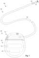
- FIG. 1illustrates schematically one embodiment of an optical stimulation system 100 .
- the optical stimulation systemincludes a control module (e.g., a stimulator) 102 and a lead 103 coupleable to the control module 102 .
- the lead 103includes one or more lead bodies 106 .
- the lead 103is shown having a single lead body 106 .
- the lead 103includes two lead bodies. It will be understood that the lead 103 can include any suitable number of lead bodies including, for example, one, two, three, four, five, six, seven, eight or more lead bodies 106 .
- At least one light emitter 135is provided at a distal end of the lead 103 .
- the light emitter 135can be a light source, such as a light emitting diode (LED), laser diode, organic light emitting diode (OLED), or the like.
- the leadcan also include one or more electrodes 134 disposed along the lead body 106 , and one or more terminals (e.g., 310 in FIG. 2 A- 2 B ) disposed along each of the one or more lead bodies 106 and coupled to the optional electrodes 134 by conductors (not shown).
- one or more terminalse.g., 310 in FIG. 2 A- 2 B
- the lead 103can be coupled to the control module 102 in any suitable manner.
- the leadis permanently attached to the control module 102 .
- the leadcan be coupled to the control module 102 by a connector (e.g., connector 144 of FIG. 2 A ).
- the lead 103is shown coupling directly to the control module 102 through the connector 144 .
- the lead 103couples to the control module 102 via one or more intermediate devices, as illustrated in FIG. 2 B .
- one or more lead extensions 324see e.g., FIG.
- the intermediate devicescan be configured into any suitable arrangement.
- the control module 102can include, for example, a connector housing 112 and a sealed electronics housing 114 .
- An electronic subassembly 110 and an optional power source 120are disposed in the electronics housing 114 .
- a control module connector 144is disposed in the connector housing 112 .
- the control module connector 144is configured and arranged to make an electrical connection between the lead 103 and the electronic subassembly 110 of the control module 102 .
- the stimulation system or components of the stimulation systemare typically implanted into the body of a patient.
- the stimulation systemcan be used for a variety of applications including, but not limited to brain stimulation, deep brain stimulation, neural stimulation, spinal cord stimulation, muscle stimulation, and the like.
- the electrodescan be formed using any conductive, biocompatible material. Examples of suitable materials include metals, alloys, conductive polymers, conductive carbon, and the like, as well as combinations thereof.
- one or more of the electrodes 134are formed from one or more of: platinum, platinum iridium, palladium, palladium rhodium, or titanium. Any suitable number of electrodes 134 can be disposed on the lead including, for example, one, two, three, four, five, six, seven, eight, nine, ten, eleven, twelve, fourteen, sixteen, twenty-four, thirty-two, or more electrodes 134 .
- the one or more lead bodies 106are made of a non-conductive, biocompatible material such as, for example, silicone, polyurethane, polyetheretherketone (“PEEK”), epoxy, and the like or combinations thereof.
- the one or more lead bodies 106may be formed in the desired shape by any process including, for example, molding (including injection molding), casting, and the like.
- One or more terminalsare typically disposed along the proximal end of the one or more lead bodies 106 of the stimulation system 100 (as well as any splitters, lead extensions, adaptors, or the like) for electrical connection to corresponding connector contacts (e.g., 314 in FIGS. 2 A- 2 B ).
- the connector contactsare disposed in connectors (e.g., 144 in FIGS. 1 - 2 B ; and 322 FIG. 2 B ) which, in turn, are disposed on, for example, the control module 102 (or a lead extension, a splitter, an adaptor, or the like).
- Electrically conductive wires, cables, or the likeextend from the terminals to the light emitter 135 or optional one or more electrodes 134 .
- the electrically conductive wiresmay be embedded in the non-conductive material of the lead body 106 or can be disposed in one or more lumens (not shown) extending along the lead body 106 . In some embodiments, there is an individual lumen for each conductor. In other embodiments, two or more conductors extend through a lumen. There may also be one or more lumens (not shown) that open at, or near, the proximal end of the one or more lead bodies 106 , for example, for inserting a stylet to facilitate placement of the one or more lead bodies 106 within a body of a patient.
- the one or more lumensmay be flushed continually, or on a regular basis, with saline, epidural fluid, or the like.
- the one or more lumensare permanently or removably sealable at the distal end.
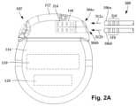
- FIG. 2 Ais a schematic side view of one embodiment of a proximal end of one or more elongated devices 300 configured and arranged for coupling to one embodiment of the control module connector 144 .
- the one or more elongated devicesmay include, for example, one or more of the lead bodies 106 of FIG. 1 , one or more intermediate devices (e.g., a splitter, the lead extension 324 of FIG. 2 B , an adaptor, or the like or combinations thereof), or a combination thereof.
- the control module connector 144defines at least one port into which a proximal end of the elongated device 300 can be inserted, as shown by directional arrows 312 a and 312 b .
- the connector housing 112is shown having two ports 304 a and 304 b .
- the connector housing 112can define any suitable number of ports including, for example, one, two, three, four, five, six, seven, eight, or more ports.
- the control module connector 144also includes a plurality of connector contacts, such as connector contact 314 , disposed within each port 304 a and 304 b .
- the connector contacts 314can be aligned with a plurality of terminals 310 disposed along the proximal end(s) of the elongated device(s) 300 to electrically couple the control module 102 to the electrodes ( 134 of FIG. 1 ) disposed on the paddle body 104 of the lead 103 .
- Each of the terminals 310can couple to the light emitter 135 or one or more of the optional electrodes 134 . Examples of connectors in control modules are found in, for example, U.S. Pat. Nos. 7,244,150 and 8,224,450, which are incorporated by reference.
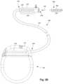
- FIG. 2 Bis a schematic side view of another embodiment of the stimulation system 100 .
- the stimulation system 100includes a lead extension 324 that is configured and arranged to couple one or more elongated devices 300 (e.g., one of the lead bodies 106 of FIG. 1 , a splitter, an adaptor, another lead extension, or the like or combinations thereof) to the control module 102 .
- the lead extension 324is shown coupled to a single port 304 defined in the control module connector 144 .
- the lead extension 324is shown configured and arranged to couple to a single elongated device 300 .
- the lead extension 324is configured and arranged to couple to multiple ports 304 defined in the control module connector 144 (e.g., the ports 304 a and 304 b of FIG. 1 ), or to receive multiple elongated devices 300 (e.g., both of the lead bodies 106 of FIG. 1 ), or both.
- a lead extension connector 322is disposed on the lead extension 324 .
- the lead extension connector 322is shown disposed at a distal end 326 of the lead extension 324 .
- the lead extension connector 322includes a connector housing 328 .
- the connector housing 328defines at least one port 330 into which terminals 310 of the elongated device 300 can be inserted, as shown by directional arrow 338 .
- Each of the terminals 310can couple to the light emitter 135 or one or more of the optional electrodes 134 .
- the connector housing 328also includes a plurality of connector contacts, such as connector contact 340 .
- the connector contacts 340 disposed in the connector housing 328can be aligned with the terminals 310 of the elongated device 300 to electrically couple the lead extension 324 to the electrodes ( 134 of FIG. 1 ) disposed along the lead ( 103 in FIG. 1 ).
- the proximal end of the lead extension 324is similarly configured and arranged as a proximal end of the lead 103 (or other elongated device 300 ).
- the lead extension 324may include a plurality of electrically conductive wires (not shown) that electrically couple the connector contacts 340 to a proximal end 348 of the lead extension 324 that is opposite to the distal end 326 .
- the conductive wires disposed in the lead extension 324can be electrically coupled to a plurality of terminals (not shown) disposed along the proximal end 348 of the lead extension 324 .
- the proximal end 348 of the lead extension 324is configured and arranged for insertion into a connector disposed in another lead extension (or another intermediate device). In other embodiments (and as shown in FIG. 2 B ), the proximal end 348 of the lead extension 324 is configured and arranged for insertion into the control module connector 144 .
- FIG. 3 Aillustrates the distal end of one embodiment of a lead 403 with a lead body 406 , an optical assembly 460 containing a light emitter 435 attached to the distal end of the lead body, and two optional electrodes 434 disposed along the lead body.
- FIG. 3 Bis an exploded view of the components of the optical assembly 460 .
- the optical assembly 460provides a hermetically sealed housing for the light emitter 435 .
- the optical assembly 460includes the light emitter 435 , an emitter cover 462 , a feedthrough assembly 464 , feedthrough pins 466 , conductive cables 468 , a metal tube 470 , and an anchor 472 .
- the light emitter 435emits light in response to electrical signals transmitted along the lead 403 .
- Any suitable light emittercan be used including, but not limited to, a light emitting diode (LED), laser diode, organic light emitting diode (OLED), or the like.
- the light emitter 435can emit one or more wavelengths of light or can emit light in one or more wavelength bands.
- the wavelength or wavelength bandcan be visible, infrared, or ultraviolet light.
- the light emitter 435emits visible light. In at least some embodiments, the light emitter 435 emits light at one or more wavelengths in a range of 500 to 800 nm or in a range of 600 to 700 nm.
- FIGS. 3 A and 3 Billustrate a single light emitter 435 , it will be understood that other embodiments can include multiple light emitters. Those light emitters may emit light at a same wavelength or wavelength band or some, or all, of the light emitters may emit light at different wavelengths or wavelength bands.
- the light emitter 435includes an emitter element 480 , a flange 482 or other housing, and at least two contacts 484 .
- the emitter element 480may also include a protective material (such as a ceramic or polymeric material) disposed around the actual light emitting structure.
- the flange 482can be made of any suitable material and may provide structural or positional stability for the emitter element 480 within the optical assembly 460 .
- the contacts 484can be pins, pads, or any other structure that provides for electrical coupling of the emitter element 480 to other components, such as the conductive cables 468 or feedthrough pins 466 .
- the conductive cables 468 of the optical assembly 460can be conductive wires, pins, or any other suitable conductive structure to electrically couple the contacts 484 of the light emitter 435 to the feedthrough pins 466 . It will be understood that in other embodiments, the contacts 484 can be coupled directly to the feedthrough pins 466 without the use of conductive cables.
- an emitter cover 462is disposed over the light emitter 435 .
- the emitter cover 462can be an optical component such as an optical diffuser or lens.
- a sapphire optical diffuser domecan be positioned over the light emitter.
- the emitter cover 462may be an optically transparent or translucent material to seal the light emitter 435 within the optical assembly 460 .
- the emitter cover 462can be part of a package that forms the light emitter 435 .
- FIG. 3 Cillustrates an exploded view of one embodiment of the feedthrough assembly 464 which includes a ceramic block 474 through which the feedthrough pins 466 pass and a metal housing 476 surrounding a portion of the ceramic block.
- the ceramic block 474 and metal housing 476are physically attached together by a braze joint 490 .
- the metal housing 476can be made of titanium and the braze joint 490 can be a gold (or gold alloy) braze joint.
- other methods of attachmentcan be use such as, for example, an adhesive, or the ceramic block 474 and metal housing 476 may be coupled together by a frictional, interference, or compression fit or any combination thereof.
- the feedthrough pins 466are also made of metal.
- the ceramic block 474 and feedthrough pins 466are physically attached together by a braze joint 492 .
- the feedthrough pins 466can be made of platinum, iridium, platinum/iridium alloy, or any other suitable material and the braze joint 490 can be a gold (or gold alloy) braze joint.
- other methods of attachmentcan be use such as, for example, an adhesive, or the ceramic block 474 and feedthrough pins 466 may be coupled together by a frictional, interference, or compression fit or any combination thereof.
- the anchor 472is coupled to, and extends away from, the feedthrough assembly 464 .
- the anchor 472can be made of metal or any other suitable material and is shaped to fit into a lumen 480 in the lead body 406 .
- the anchor 472can be physical attached to the ceramic block 474 (or, in other embodiments, the metal housing 476 ) by a braze joint 494 (for example, a gold or gold alloy braze for a titanium anchor) or using adhesive or any other suitable attachment method or the ceramic block 474 and anchor 472 can be coupled by a frictional, interference, or compression fit, or any combination thereof.
- the anchor 472forms a frictional or compression fit with the lumen 480 of the lead body.
- the polymeric material of the lead body 406may be heated to allow the material to reflow around the anchor 472 to enhance the attachment of the anchor to the lead body.
- the anchor 472can include a flange 473 at the proximal end of the anchor to engage the lead body 406 . In the illustrated body, the flange 473 tapers in a proximal direction to facilitate inserting the anchor 472 into the lumen 480 of the lead body 406 .
- a metal tube 470is disposed around the light emitter 435 and coupled to the metal housing 476 of the feedthrough assembly 464 .
- the metal housing 476can be attached to the metal tube 470 by welding or any other suitable attachment method including, but not limited to, adhesive or a frictional, interference, or compression fit, or any combination thereof.
- the metal tube 470can be attached to the optical diffuser or lens 462 by brazing, adhesive, or a frictional, interference, or compression fit, or any combination thereof.
- the optical assembly 460provides a hermetically sealed housing for the light emitter 435 which prevents or resists the flow of fluids into the optical assembly 460 .
- the use of welding and brazing to couple the components of the optical assembly 460may facilitate or provide the hermetical sealing of the optical assembly 460 .
- the lead body 406 of the illustrated embodimentincludes a central lumen 480 and multiple peripheral lumens 481 .
- the anchor 472can be inserted into the distal portion of the central lumen 480 .
- the central lumenmay also be used for insertion of a stylet during implantation, as discussed above.
- One or more of the peripheral lumens 481can carry conductors (not shown), such as conductive wires or cables.
- the feedthrough pins 466can be inserted into one or more of the peripheral lumens 481 and can be coupled to the conductors carried in those lumens in order to transmit electrical signals from the control module through the conductors to the optical assembly 460 .
- conductors in one or more of the peripheral lumens 481can also be coupled to the optional electrodes 434 , as described above and in the references cited above.
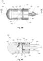
- FIGS. 4 A- 4 Cillustrate another embodiment of an optical assembly 560 for a lead 403 ( FIG. 3 A ).
- the optical assemblyincludes a light emitter 535 , an emitter cover 562 , a feedthrough assembly 564 , one or more feedthrough pins 566 , a connector plate 567 , an insulator disc 569 , a metal tube 570 , a distal seal 571 , and an anchor 572 .
- the light emitter 535emits light in response to electrical signals transmitted along the lead 403 .
- the anchor 572is similar to anchor 472 described above and can be attached to the lead 403 using any of the same methods and arrangements described above.
- FIG. 4 Ais an exploded view and FIG. 4 B is an assembled view of the optical assembly 560 .
- FIG. 4 Cis a cross-sectional view of the optical assembly 560 and further illustrates that the feedthrough assembly 564 includes two ceramic blocks 574 (although in other embodiments, a single ceramic block forming an annulus around the anchor 572 can be used) through which the feedthrough pins 566 pass and a metal housing 576 surrounding the ceramic blocks.
- a joint 577( FIGS. 4 B and 4 C ) (for example, a weld joint) is formed between the metal tube 570 and metal housing 576 .
- the ceramic blocks 574 and metal housing 576are physically or chemically attached together to form a seal or, preferably, a hermetic seal.
- the metal housing 576can be made of titanium or other metal and the ceramic blocks 574 can be made of KryoflexTM (available from PA&E, Wenatchee, WA) or other ceramic material that can form a hermetic seal with the metal housing when both are fired or otherwise chemically activated.
- the metal housing 576 and ceramic blocks 574can be joined to form a seal (or, in some embodiments, a hermetic seal) by brazing or other joining techniques such as, for example, an adhesive, or the ceramic blocks 574 and metal housing 576 may be coupled together by a frictional, interference, or compression fit or any combination thereof.
- the feedthrough pins 466 and the anchor 462are made of metal and can be joined to the ceramic blocks 574 using the same methods of joining as described above for joining the metal housing 576 and ceramic blocks 574 .
- the proximal seal 572can be made of a ceramic material, such as KryoflexTM, and can be joined to the metal tube 570 (which is made of titanium or other metal) using the same methods of joining as described above for joining the metal housing 576 and ceramic blocks 574 .
- the metal tube 570 and metal housing 576are then joined by welding or other suitable joining techniques.
- any suitable light emitter 535can be used including, but not limited to, the light emitters described above for use as light emitter 435 .
- the light emitter 535includes an emitter element, a housing, and at least two contacts, as describe above for light emitter 535 .
- the contacts of the light emittercan be pins, pads, or any other structure.
- One contactis coupled to one of the feedback pins 566 (directly or through a conductor 568 illustrated in FIG. 4 A ) and the other contact is coupled to the other feedback pin 566 using the conductor plate 567 (for example, a nickel conductor plate) and, optionally, a conductive adhesive, conductive wire, or the like.
- An insulator disc 569(for example, a disc made of KaptonTM) is provided under conductor plate 567 to provide insulation between the two feedback pins 566 and the metal housing 576 of the feedback assembly 564 .
- an emitter cover 562is disposed over the light emitter 535 .
- the emitter cover 562can be an optical component such as an optical diffuser or lens.
- a sapphire optical diffuser domecan be positioned over the light emitter.
- the emitter cover 562may be an optically transparent or translucent material to seal the light emitter 535 within the optical assembly 560 .
- the emitter cover 562can be part of a package that forms the light emitter 535 .
- the optical assembly 560provides a hermetically sealed housing for the light emitter 535 which prevents or resists the flow of fluids into the optical assembly 560 .
- the use of welding, brazing, or KryoflexTM or combinations thereof to couple the components of the optical assembly 560 , as described above,may facilitate or provide the hermetical sealing of the optical assembly 560 .
- FIG. 5is a schematic overview of one embodiment of components of an optical stimulation system 500 including an electronic subassembly 610 disposed within a control module. It will be understood that the optical stimulation system can include more, fewer, or different components and can have a variety of different configurations including those configurations disclosed in the stimulator references cited herein.
- a power source 612can be used including, for example, a battery such as a primary battery or a rechargeable battery.
- a batterysuch as a primary battery or a rechargeable battery.
- other power sourcesinclude super capacitors, nuclear or atomic batteries, mechanical resonators, infrared collectors, thermally-powered energy sources, flexural powered energy sources, bioenergy power sources, fuel cells, bioelectric cells, osmotic pressure pumps, and the like including the power sources described in U.S. Pat. No. 7,437,193, incorporated herein by reference.
- powercan be supplied by an external power source through inductive coupling via the optional antenna 618 or a secondary antenna.
- the external power sourcecan be in a device that is mounted on the skin of the user or in a unit that is provided near the user on a permanent or periodic basis.
- the batterymay be recharged using the optional antenna 618 , if desired. Power can be provided to the battery for recharging by inductively coupling the battery through the antenna to a recharging unit 616 external to the user. Examples of such arrangements can be found in the references identified above.
- lightis emitted by the light emitter 135 of the lead body to stimulate nerve fibers, muscle fibers, or other body tissues near the optical stimulation system.
- the processor 604is generally included to control the timing and other characteristics of the optical stimulation system. For example, the processor 604 can, if desired, control one or more of the timing, pulse frequency, strength, duration, and waveform of the optical stimulation. In addition, the processor 604 can select one or more of the optional electrodes to provide electrical stimulation, if desired. In some embodiments, the processor 604 selects which of the optional electrode(s) are cathodes and which electrode(s) are anodes.
- Any processorcan be used and can be as simple as an electronic device that, for example, produces optical stimulation at a regular interval or the processor can be capable of receiving and interpreting instructions from an external programming unit 608 that, for example, allows modification of stimulation characteristics.
- the processor 604is coupled to a receiver 602 which, in turn, is coupled to the optional antenna 618 . This allows the processor 604 to receive instructions from an external source to, for example, direct the stimulation characteristics and the selection of electrodes, if desired.
- the antenna 618is capable of receiving signals (e.g., RF signals) from an external telemetry unit 606 which is programmed by the programming unit 608 .
- the programming unit 608can be external to, or part of, the telemetry unit 606 .
- the telemetry unit 606can be a device that is worn on the skin of the user or can be carried by the user and can have a form similar to a pager, cellular phone, or remote control, if desired.
- the telemetry unit 606may not be worn or carried by the user but may only be available at a home station or at a clinician's office.
- the programming unit 608can be any unit that can provide information to the telemetry unit 606 for transmission to the optical stimulation system 600 .
- the programming unit 608can be part of the telemetry unit 606 or can provide signals or information to the telemetry unit 606 via a wireless or wired connection.
- One example of a suitable programming unitis a computer operated by the user or clinician to send signals to the telemetry unit 606 .
- the signals sent to the processor 604 via the antenna 618 and the receiver 602can be used to modify or otherwise direct the operation of the optical stimulation system.
- the signalsmay be used to modify the stimulation characteristics of the optical stimulation system such as modifying one or more of stimulation duration, pulse frequency, waveform, and stimulation amplitude.
- the signalsmay also direct the optical stimulation system 600 to cease operation, to start operation, to start charging the battery, or to stop charging the battery.
- the stimulation systemdoes not include the antenna 618 or receiver 602 and the processor 604 operates as programmed.
- the optical stimulation system 600may include a transmitter (not shown) coupled to the processor 604 and the antenna 618 for transmitting signals back to the telemetry unit 606 or another unit capable of receiving the signals.
- the optical stimulation system 600may transmit signals indicating whether the optical stimulation system 600 is operating properly or not or indicating when the battery needs to be charged or the level of charge remaining in the battery.
- the processor 604may also be capable of transmitting information about the stimulation characteristics so that a user or clinician can determine or verify the characteristics.
Landscapes
- Health & Medical Sciences (AREA)
- Biomedical Technology (AREA)
- Engineering & Computer Science (AREA)
- Life Sciences & Earth Sciences (AREA)
- Animal Behavior & Ethology (AREA)
- Public Health (AREA)
- Radiology & Medical Imaging (AREA)
- Nuclear Medicine, Radiotherapy & Molecular Imaging (AREA)
- Veterinary Medicine (AREA)
- General Health & Medical Sciences (AREA)
- Pathology (AREA)
- Biophysics (AREA)
- Neurosurgery (AREA)
- Cardiology (AREA)
- Heart & Thoracic Surgery (AREA)
- Physics & Mathematics (AREA)
- Optics & Photonics (AREA)
- Electrotherapy Devices (AREA)
Abstract
Description
This application is a continuation of U.S. patent application Ser. No. 16/412,157, filed May 14, 2019, which is a continuation of U.S. patent application Ser. No. 15/421,001, filed Jan. 31, 2017, which issued as U.S. Pat. No. 10,335,607 on Jul. 2, 2019, which claims priority to U.S. Provisional Patent Application Ser. No. 62/292,083, filed Feb. 5, 2016, and U.S. Provisional Patent Application Ser. No. 62/424,130, filed Nov. 18, 2016, all of which are incorporated herein by reference in their entirety.
The present invention is directed to the area of implantable optical stimulation systems and methods of making and using the systems. The present invention is also directed to implantable optical stimulation leads having a light source at the distal end of the lead, as well as methods of making and using the leads and optical stimulation systems.
Implantable optical stimulation systems can provide therapeutic benefits in a variety of diseases and disorders. For example, optical stimulation can be applied to the brain either externally or using an implanted stimulation lead to provide, for example, deep brain stimulation, to treat a variety of diseases or disorders. Optical stimulation may also be combined with electrical stimulation.
Stimulators have been developed to provide therapy for a variety of treatments. A stimulator can include a control module (for generating light or electrical signals sent to light sources in a lead), one or more leads, and one or more light sources coupled to, or disposed within, each lead. The lead is positioned near the nerves, muscles, or other tissue to be stimulated.
One embodiment is an optical stimulation lead including a lead body including a distal end, a distal portion, and a proximal portion; and an optical assembly attached to the distal end of the lead body. The optical assembly includes a light emitter; a feedthrough assembly including at least one ceramic block, at least one feedthrough pin extending through the at least one ceramic block and electrically coupled to the light emitter, and a metal housing attached to the at least one ceramic block; a metal tube attached to the feedthrough assembly and disposed around the light emitter; and an emitter cover disposed over the light emitter and coupled to the metal tube.
In at least some embodiments, the optical assembly forms a hermetically sealed housing for the light emitter. In at least some embodiments, the optical assembly further includes an anchor extending proximally from the feedthrough assembly, where the anchor is configured and arranged to be inserted into the distal end of the lead body to anchor the optical assembly to the lead body. In at least some embodiments, the anchor includes a proximally tapered flange to facilitate attachment of the anchor to the lead body. In at least some embodiments, the lead body defines a lumen to receive at least a portion of the anchor to facilitate attachment of the anchor to the lead body. In at least some embodiments, the at least one ceramic block is attached to the anchor with a braze joint.
In at least some embodiments, the at least one ceramic block is attached to the metal housing with a braze joint. In at least some embodiments, the at least one ceramic block is attached to the at least one feedthrough pin with a braze joint. In at least some embodiments, the optical stimulation lead further includes at least one lead cable disposed within the optical assembly to electrically couple the at least one feedthrough pin to the light emitter.
In at least some embodiments, the at least one ceramic block is attached to the anchor to form a hermetic seal. In at least some embodiments, the at least one ceramic block is attached to the metal housing to form a hermetic seal. In at least some embodiments, the at least one ceramic block is attached to the at least one feedthrough pin to form a hermetic seal.
In at least some embodiments, the optical stimulation lead further includes terminals disposed along the proximal portion of the lead body and conductors extending along the lead body, where at least one of the conductors electrically couples the at least one feedthrough pin to at least one of the terminals of the lead. In at least some embodiments, the optical stimulation lead further includes at least one electrode disposed along the distal portion of the lead body. In at least some embodiments, at least one of the conductors electrically couples the at least one electrode to at least one of the terminals of the lead. In at least some embodiments, the lead body defines a lumens extending along the lead body, where the conductors are disposed in at least one of the lumens.
In at least some embodiments, the emitter covering is an optical diffuser. In at least some embodiments, the emitter covering is a lens.
Another embodiment is an optical stimulation system including any of the optical stimulation leads described above and a control module coupleable to the optical stimulation lead. The control module includes a housing and an electronic subassembly disposed in the housing to provide electrical signals to the light emitter of the optical stimulation lead.
In at least some embodiments, the lead further includes terminals disposed along the proximal portion of the lead body and the optical stimulation system further includes a connector for receiving the proximal portion of the lead body, the connector having a proximal end, a distal end, and a longitudinal length, the connector including a connector housing defining a port at the distal end of the connector, the port configured and arranged for receiving the proximal portion of the lead body of the optical stimulation lead, and connector contacts disposed in the connector housing, the connector contacts configured and arranged to couple to the terminals disposed along the proximal portion of the lead body of the optical stimulation lead.
In at least some embodiments, the connector is part of the control module. In at least some embodiments, the electrical stimulation system further includes a lead extension coupleable to both the electrical stimulation lead and the control module, where the connector is part of the lead extension.
Yet another embodiment is a method of stimulating patient tissue that includes implanting any of the optical stimulation leads described above into the patient tissue; and emitting light from the light emitter of the optical stimulation lead to stimulate the patient tissue.
Non-limiting and non-exhaustive embodiments of the present invention are described with reference to the following drawings. In the drawings, like reference numerals refer to like parts throughout the various figures unless otherwise specified.
For a better understanding of the present invention, reference will be made to the following Detailed Description, which is to be read in association with the accompanying drawings, wherein:
The present invention is directed to the area of implantable optical stimulation systems and methods of making and using the systems. The present invention is also directed to implantable optical stimulation leads having a light source at the distal end of the lead, as well as methods of making and using the leads and optical stimulation systems.
In some embodiments, the implantable optical stimulation system only provides optical stimulation. In other embodiments, the stimulation system can include both optical and electrical stimulation. In at least some of these embodiments, the optical stimulation system can be a modification of an electrical stimulation system to also provide optical stimulation. Suitable implantable electrical stimulation systems that can be modified to also provide optical stimulation include, but are not limited to, a least one lead with one or more electrodes disposed along a distal end of the lead and one or more terminals disposed along the one or more proximal ends of the lead. Leads include, for example, percutaneous leads, paddle leads, and cuff leads. Examples of electrical stimulation systems with leads are found in, for example, U.S. Pat. Nos. 6,181,969; 6,516,227; 6,609,029; 6,609,032; 6,741,892; 7,244,150; 7,450,997; 7,672,734; 7,761,165; 7,783,359; 7,792,590; 7,809,446; 7,949,395; 7,974,706; 6,175,710; 6,224,450; 6,271,094; 6,295,944; 6,364,278; and 6,391,985; U.S. Patent Applications Publication Nos. 2007/0150036; 2009/0187222; 2009/0276021; 2010/0076535; 2010/0268298; 2011/0004267; 2011/0078900; 2011/0130817; 2011/0130818; 2011/0238129; 2011/0313500; 2012/0016378; 2012/0046710; 2012/0071949; 2012/0165911; 2012/0197375; 2012/0203316; 2012/0203320; 2012/0203321; 2012/0316615; and 2013/0105071; and U.S. patent application Ser. Nos. 12/177,823 and 13/750,725, all of which are incorporated by reference in their entireties.
At least onelight emitter 135 is provided at a distal end of thelead 103. Thelight emitter 135 can be a light source, such as a light emitting diode (LED), laser diode, organic light emitting diode (OLED), or the like. Optionally, the lead can also include one ormore electrodes 134 disposed along thelead body 106, and one or more terminals (e.g.,310 inFIG.2A-2B ) disposed along each of the one or morelead bodies 106 and coupled to theoptional electrodes 134 by conductors (not shown). In at least some embodiments, one or more terminals (e.g.,310 inFIG.2A-2B ) may also be used to convey electrical signals to a light source that acts as thelight emitter 135 by conductors (not shown) extending along the lead.
Thelead 103 can be coupled to thecontrol module 102 in any suitable manner. In some embodiments, the lead is permanently attached to thecontrol module 102. In other embodiments, the lead can be coupled to thecontrol module 102 by a connector (e.g.,connector 144 ofFIG.2A ). InFIG.2A , thelead 103 is shown coupling directly to thecontrol module 102 through theconnector 144. In at least some other embodiments, thelead 103 couples to thecontrol module 102 via one or more intermediate devices, as illustrated inFIG.2B . For example, in at least some embodiments one or more lead extensions324 (see e.g.,FIG.2B ) can be disposed between the lead103 and thecontrol module 102 to extend the distance between the lead103 and thecontrol module 102. Other intermediate devices may be used in addition to, or in lieu of, one or more lead extensions including, for example, a splitter, an adaptor, or the like or combinations thereof. It will be understood that, in the case where thestimulation system 100 includes multiple elongated devices disposed between the lead103 and thecontrol module 102, the intermediate devices may be configured into any suitable arrangement.
Thecontrol module 102 can include, for example, aconnector housing 112 and a sealedelectronics housing 114. Anelectronic subassembly 110 and anoptional power source 120 are disposed in theelectronics housing 114. Acontrol module connector 144 is disposed in theconnector housing 112. Thecontrol module connector 144 is configured and arranged to make an electrical connection between the lead103 and theelectronic subassembly 110 of thecontrol module 102.
The stimulation system or components of the stimulation system, including thelead 103 and thecontrol module 102, are typically implanted into the body of a patient. The stimulation system can be used for a variety of applications including, but not limited to brain stimulation, deep brain stimulation, neural stimulation, spinal cord stimulation, muscle stimulation, and the like.
If the lead includes theoptional electrodes 134, the electrodes can be formed using any conductive, biocompatible material. Examples of suitable materials include metals, alloys, conductive polymers, conductive carbon, and the like, as well as combinations thereof. In at least some embodiments, one or more of theelectrodes 134 are formed from one or more of: platinum, platinum iridium, palladium, palladium rhodium, or titanium. Any suitable number ofelectrodes 134 can be disposed on the lead including, for example, one, two, three, four, five, six, seven, eight, nine, ten, eleven, twelve, fourteen, sixteen, twenty-four, thirty-two, ormore electrodes 134.
The one or morelead bodies 106 are made of a non-conductive, biocompatible material such as, for example, silicone, polyurethane, polyetheretherketone (“PEEK”), epoxy, and the like or combinations thereof. The one or morelead bodies 106 may be formed in the desired shape by any process including, for example, molding (including injection molding), casting, and the like.
One or more terminals (e.g.,310 inFIGS.2A-2B ) are typically disposed along the proximal end of the one or morelead bodies 106 of the stimulation system100 (as well as any splitters, lead extensions, adaptors, or the like) for electrical connection to corresponding connector contacts (e.g.,314 inFIGS.2A-2B ). The connector contacts are disposed in connectors (e.g.,144 inFIGS.1-2B ; and322FIG.2B ) which, in turn, are disposed on, for example, the control module102 (or a lead extension, a splitter, an adaptor, or the like). Electrically conductive wires, cables, or the like (not shown) extend from the terminals to thelight emitter 135 or optional one ormore electrodes 134.
The electrically conductive wires (“conductors”) may be embedded in the non-conductive material of thelead body 106 or can be disposed in one or more lumens (not shown) extending along thelead body 106. In some embodiments, there is an individual lumen for each conductor. In other embodiments, two or more conductors extend through a lumen. There may also be one or more lumens (not shown) that open at, or near, the proximal end of the one or morelead bodies 106, for example, for inserting a stylet to facilitate placement of the one or morelead bodies 106 within a body of a patient. Additionally, there may be one or more lumens (not shown) that open at, or near, the distal end of the one or morelead bodies 106, for example, for infusion of drugs or medication into the site of implantation of the one or morelead bodies 106. In at least one embodiment, the one or more lumens are flushed continually, or on a regular basis, with saline, epidural fluid, or the like. In at least some embodiments, the one or more lumens are permanently or removably sealable at the distal end.
Thecontrol module connector 144 defines at least one port into which a proximal end of theelongated device 300 can be inserted, as shown bydirectional arrows FIG.2A (and in other figures), theconnector housing 112 is shown having twoports connector housing 112 can define any suitable number of ports including, for example, one, two, three, four, five, six, seven, eight, or more ports.
Thecontrol module connector 144 also includes a plurality of connector contacts, such asconnector contact 314, disposed within eachport elongated device 300 is inserted into theports connector contacts 314 can be aligned with a plurality ofterminals 310 disposed along the proximal end(s) of the elongated device(s)300 to electrically couple thecontrol module 102 to the electrodes (134 ofFIG.1 ) disposed on the paddle body104 of thelead 103. Each of theterminals 310 can couple to thelight emitter 135 or one or more of theoptional electrodes 134. Examples of connectors in control modules are found in, for example, U.S. Pat. Nos. 7,244,150 and 8,224,450, which are incorporated by reference.
Alead extension connector 322 is disposed on thelead extension 324. InFIG.2B , thelead extension connector 322 is shown disposed at adistal end 326 of thelead extension 324. Thelead extension connector 322 includes aconnector housing 328. Theconnector housing 328 defines at least oneport 330 into whichterminals 310 of theelongated device 300 can be inserted, as shown bydirectional arrow 338. Each of theterminals 310 can couple to thelight emitter 135 or one or more of theoptional electrodes 134. Theconnector housing 328 also includes a plurality of connector contacts, such asconnector contact 340. When theelongated device 300 is inserted into theport 330, theconnector contacts 340 disposed in theconnector housing 328 can be aligned with theterminals 310 of theelongated device 300 to electrically couple thelead extension 324 to the electrodes (134 ofFIG.1 ) disposed along the lead (103 inFIG.1 ).
In at least some embodiments, the proximal end of thelead extension 324 is similarly configured and arranged as a proximal end of the lead103 (or other elongated device300). Thelead extension 324 may include a plurality of electrically conductive wires (not shown) that electrically couple theconnector contacts 340 to aproximal end 348 of thelead extension 324 that is opposite to thedistal end 326. In at least some embodiments, the conductive wires disposed in thelead extension 324 can be electrically coupled to a plurality of terminals (not shown) disposed along theproximal end 348 of thelead extension 324. In at least some embodiments, theproximal end 348 of thelead extension 324 is configured and arranged for insertion into a connector disposed in another lead extension (or another intermediate device). In other embodiments (and as shown inFIG.2B ), theproximal end 348 of thelead extension 324 is configured and arranged for insertion into thecontrol module connector 144.
In the illustrated embodiment ofFIGS.3A and3B , theoptical assembly 460 includes thelight emitter 435, anemitter cover 462, afeedthrough assembly 464, feedthrough pins466,conductive cables 468, ametal tube 470, and ananchor 472. Thelight emitter 435 emits light in response to electrical signals transmitted along thelead 403. Any suitable light emitter can be used including, but not limited to, a light emitting diode (LED), laser diode, organic light emitting diode (OLED), or the like. Thelight emitter 435 can emit one or more wavelengths of light or can emit light in one or more wavelength bands. The wavelength or wavelength band can be visible, infrared, or ultraviolet light. In at least some embodiments, thelight emitter 435 emits visible light. In at least some embodiments, thelight emitter 435 emits light at one or more wavelengths in a range of 500 to 800 nm or in a range of 600 to 700 nm. AlthoughFIGS.3A and3B illustrate asingle light emitter 435, it will be understood that other embodiments can include multiple light emitters. Those light emitters may emit light at a same wavelength or wavelength band or some, or all, of the light emitters may emit light at different wavelengths or wavelength bands.
In at least some embodiments, thelight emitter 435 includes anemitter element 480, aflange 482 or other housing, and at least twocontacts 484. Theemitter element 480 may also include a protective material (such as a ceramic or polymeric material) disposed around the actual light emitting structure. Theflange 482 can be made of any suitable material and may provide structural or positional stability for theemitter element 480 within theoptical assembly 460. Thecontacts 484 can be pins, pads, or any other structure that provides for electrical coupling of theemitter element 480 to other components, such as theconductive cables 468 or feedthrough pins466. Theconductive cables 468 of theoptical assembly 460 can be conductive wires, pins, or any other suitable conductive structure to electrically couple thecontacts 484 of thelight emitter 435 to the feedthrough pins466. It will be understood that in other embodiments, thecontacts 484 can be coupled directly to the feedthrough pins466 without the use of conductive cables.
In at least some embodiments, anemitter cover 462 is disposed over thelight emitter 435. In at least some embodiments, theemitter cover 462 can be an optical component such as an optical diffuser or lens. For example, a sapphire optical diffuser dome can be positioned over the light emitter. In other embodiments, theemitter cover 462 may be an optically transparent or translucent material to seal thelight emitter 435 within theoptical assembly 460. In some embodiments, theemitter cover 462 can be part of a package that forms thelight emitter 435.
The feedthrough pins466 are also made of metal. In at least some embodiments, theceramic block 474 andfeedthrough pins 466 are physically attached together by a braze joint492. For example, the feedthrough pins466 can be made of platinum, iridium, platinum/iridium alloy, or any other suitable material and the braze joint490 can be a gold (or gold alloy) braze joint. In other embodiments, other methods of attachment can be use such as, for example, an adhesive, or theceramic block 474 and feedthrough pins466 may be coupled together by a frictional, interference, or compression fit or any combination thereof.
Theanchor 472 is coupled to, and extends away from, thefeedthrough assembly 464. Theanchor 472 can be made of metal or any other suitable material and is shaped to fit into alumen 480 in thelead body 406. Theanchor 472 can be physical attached to the ceramic block474 (or, in other embodiments, the metal housing476) by a braze joint494 (for example, a gold or gold alloy braze for a titanium anchor) or using adhesive or any other suitable attachment method or theceramic block 474 andanchor 472 can be coupled by a frictional, interference, or compression fit, or any combination thereof. In at least some embodiments, theanchor 472 forms a frictional or compression fit with thelumen 480 of the lead body. In at least some embodiments, the polymeric material of thelead body 406 may be heated to allow the material to reflow around theanchor 472 to enhance the attachment of the anchor to the lead body. In at least some embodiments, theanchor 472 can include aflange 473 at the proximal end of the anchor to engage thelead body 406. In the illustrated body, theflange 473 tapers in a proximal direction to facilitate inserting theanchor 472 into thelumen 480 of thelead body 406.
Turning back toFIGS.3A and3B , ametal tube 470 is disposed around thelight emitter 435 and coupled to themetal housing 476 of thefeedthrough assembly 464. Themetal housing 476 can be attached to themetal tube 470 by welding or any other suitable attachment method including, but not limited to, adhesive or a frictional, interference, or compression fit, or any combination thereof. Themetal tube 470 can be attached to the optical diffuser orlens 462 by brazing, adhesive, or a frictional, interference, or compression fit, or any combination thereof.
In at least some embodiments, theoptical assembly 460 provides a hermetically sealed housing for thelight emitter 435 which prevents or resists the flow of fluids into theoptical assembly 460. For example, the use of welding and brazing to couple the components of theoptical assembly 460, as described above, may facilitate or provide the hermetical sealing of theoptical assembly 460.
Thelead body 406 of the illustrated embodiment includes acentral lumen 480 and multipleperipheral lumens 481. As indicated above, theanchor 472 can be inserted into the distal portion of thecentral lumen 480. The central lumen may also be used for insertion of a stylet during implantation, as discussed above.
One or more of theperipheral lumens 481 can carry conductors (not shown), such as conductive wires or cables. In at least some embodiments, the feedthrough pins466 can be inserted into one or more of theperipheral lumens 481 and can be coupled to the conductors carried in those lumens in order to transmit electrical signals from the control module through the conductors to theoptical assembly 460. In at least some embodiments, conductors in one or more of theperipheral lumens 481 can also be coupled to theoptional electrodes 434, as described above and in the references cited above.
The feedthrough pins466 and theanchor 462 are made of metal and can be joined to theceramic blocks 574 using the same methods of joining as described above for joining themetal housing 576 andceramic blocks 574. Similarly, theproximal seal 572 can be made of a ceramic material, such as Kryoflex™, and can be joined to the metal tube570 (which is made of titanium or other metal) using the same methods of joining as described above for joining themetal housing 576 andceramic blocks 574. Themetal tube 570 andmetal housing 576 are then joined by welding or other suitable joining techniques.
Anysuitable light emitter 535 can be used including, but not limited to, the light emitters described above for use aslight emitter 435. In at least some embodiments, thelight emitter 535 includes an emitter element, a housing, and at least two contacts, as describe above forlight emitter 535. The contacts of the light emitter can be pins, pads, or any other structure. One contact is coupled to one of the feedback pins566 (directly or through aconductor 568 illustrated inFIG.4A ) and the other contact is coupled to theother feedback pin 566 using the conductor plate567 (for example, a nickel conductor plate) and, optionally, a conductive adhesive, conductive wire, or the like. An insulator disc569 (for example, a disc made of Kapton™) is provided underconductor plate 567 to provide insulation between the two feedback pins566 and themetal housing 576 of thefeedback assembly 564.
In at least some embodiments, anemitter cover 562 is disposed over thelight emitter 535. In at least some embodiments, theemitter cover 562 can be an optical component such as an optical diffuser or lens. For example, a sapphire optical diffuser dome can be positioned over the light emitter. In other embodiments, theemitter cover 562 may be an optically transparent or translucent material to seal thelight emitter 535 within theoptical assembly 560. In some embodiments, theemitter cover 562 can be part of a package that forms thelight emitter 535.
In at least some embodiments, theoptical assembly 560 provides a hermetically sealed housing for thelight emitter 535 which prevents or resists the flow of fluids into theoptical assembly 560. For example, the use of welding, brazing, or Kryoflex™ or combinations thereof to couple the components of theoptical assembly 560, as described above, may facilitate or provide the hermetical sealing of theoptical assembly 560.
Some of the components (for example, apower source 612, anantenna 618, areceiver 602, and a processor604) of the optical stimulation system can be positioned on one or more circuit boards or similar carriers within a sealed housing of an implantable pulse generator, if desired. Anypower source 612 can be used including, for example, a battery such as a primary battery or a rechargeable battery. Examples of other power sources include super capacitors, nuclear or atomic batteries, mechanical resonators, infrared collectors, thermally-powered energy sources, flexural powered energy sources, bioenergy power sources, fuel cells, bioelectric cells, osmotic pressure pumps, and the like including the power sources described in U.S. Pat. No. 7,437,193, incorporated herein by reference.
As another alternative, power can be supplied by an external power source through inductive coupling via theoptional antenna 618 or a secondary antenna. The external power source can be in a device that is mounted on the skin of the user or in a unit that is provided near the user on a permanent or periodic basis.
If thepower source 612 is a rechargeable battery, the battery may be recharged using theoptional antenna 618, if desired. Power can be provided to the battery for recharging by inductively coupling the battery through the antenna to arecharging unit 616 external to the user. Examples of such arrangements can be found in the references identified above.
In one embodiment, light is emitted by thelight emitter 135 of the lead body to stimulate nerve fibers, muscle fibers, or other body tissues near the optical stimulation system. Theprocessor 604 is generally included to control the timing and other characteristics of the optical stimulation system. For example, theprocessor 604 can, if desired, control one or more of the timing, pulse frequency, strength, duration, and waveform of the optical stimulation. In addition, theprocessor 604 can select one or more of the optional electrodes to provide electrical stimulation, if desired. In some embodiments, theprocessor 604 selects which of the optional electrode(s) are cathodes and which electrode(s) are anodes.
Any processor can be used and can be as simple as an electronic device that, for example, produces optical stimulation at a regular interval or the processor can be capable of receiving and interpreting instructions from anexternal programming unit 608 that, for example, allows modification of stimulation characteristics. In the illustrated embodiment, theprocessor 604 is coupled to areceiver 602 which, in turn, is coupled to theoptional antenna 618. This allows theprocessor 604 to receive instructions from an external source to, for example, direct the stimulation characteristics and the selection of electrodes, if desired.
In one embodiment, theantenna 618 is capable of receiving signals (e.g., RF signals) from anexternal telemetry unit 606 which is programmed by theprogramming unit 608. Theprogramming unit 608 can be external to, or part of, thetelemetry unit 606. Thetelemetry unit 606 can be a device that is worn on the skin of the user or can be carried by the user and can have a form similar to a pager, cellular phone, or remote control, if desired. As another alternative, thetelemetry unit 606 may not be worn or carried by the user but may only be available at a home station or at a clinician's office. Theprogramming unit 608 can be any unit that can provide information to thetelemetry unit 606 for transmission to theoptical stimulation system 600. Theprogramming unit 608 can be part of thetelemetry unit 606 or can provide signals or information to thetelemetry unit 606 via a wireless or wired connection. One example of a suitable programming unit is a computer operated by the user or clinician to send signals to thetelemetry unit 606.
The signals sent to theprocessor 604 via theantenna 618 and thereceiver 602 can be used to modify or otherwise direct the operation of the optical stimulation system. For example, the signals may be used to modify the stimulation characteristics of the optical stimulation system such as modifying one or more of stimulation duration, pulse frequency, waveform, and stimulation amplitude. The signals may also direct theoptical stimulation system 600 to cease operation, to start operation, to start charging the battery, or to stop charging the battery. In other embodiments, the stimulation system does not include theantenna 618 orreceiver 602 and theprocessor 604 operates as programmed.
Optionally, theoptical stimulation system 600 may include a transmitter (not shown) coupled to theprocessor 604 and theantenna 618 for transmitting signals back to thetelemetry unit 606 or another unit capable of receiving the signals. For example, theoptical stimulation system 600 may transmit signals indicating whether theoptical stimulation system 600 is operating properly or not or indicating when the battery needs to be charged or the level of charge remaining in the battery. Theprocessor 604 may also be capable of transmitting information about the stimulation characteristics so that a user or clinician can determine or verify the characteristics.
The above specification provides a description of the structure, manufacture, and use of the invention. Since many embodiments of the invention can be made without departing from the spirit and scope of the invention, the invention also resides in the claims hereinafter appended.
Claims (20)
1. An optical stimulation lead, comprising:
a lead body comprising a distal end, a distal portion, and a proximal portion; and
an optical assembly attached to the distal end of the lead body and comprising
a light emitter,
a housing disposed around the light emitter and comprising an emitter cover disposed over the light emitter and a non-conductive feedthrough block disposed between the light emitter and the lead body; and
a plurality of feedthrough pins extending through the non-conductive feedthrough block and electrically coupled to the light emitter.
2. The optical stimulation lead ofclaim 1 , wherein the housing further comprises a metal ring coupled to the non-conductive feedthrough block.
3. The optical stimulation lead ofclaim 2 , wherein the housing further comprises a metal tube coupled to the metal ring and the emitter cover.
4. The optical stimulation lead ofclaim 1 , wherein the housing is hermetically sealed.
5. The optical stimulation lead ofclaim 1 , wherein the light emitter comprises an emitter element and a flange disposed around the emitter element to provide structural or positional stability for the emitter element within the housing.
6. The optical stimulation lead ofclaim 1 , wherein the optical assembly further comprises an anchor extending proximally from the housing, wherein the anchor is configured and arranged to be inserted into the distal end of the lead body to anchor the optical assembly to the lead body.
7. The optical stimulation lead ofclaim 6 , wherein the anchor comprises a proximally tapered flange to facilitate attachment of the anchor to the lead body.
8. The optical stimulation lead ofclaim 7 , wherein the lead body defines a lumen that is configured and arranged to receive at least a portion of the anchor to facilitate attachment of the anchor to the lead body.
9. The optical stimulation lead ofclaim 6 , wherein the non-conductive feedthrough block is attached to the anchor.
10. The optical stimulation lead ofclaim 1 , further comprising a plurality of conductive cables disposed within the optical assembly to electrically couple the feedthrough pins to the light emitter.
11. The optical stimulation lead ofclaim 1 , further comprising a plurality of terminals disposed along the proximal portion of the lead body, wherein each of the feedthrough pins is electrically coupled to a different one of the terminals.
12. The optical stimulation lead ofclaim 1 , wherein the non-conductive feedthrough block comprises a ceramic block.
13. The optical stimulation lead ofclaim 1 , wherein the lead body defines a plurality of lumens extending along the lead body and conductors extending along at least one of the lumens, wherein each of the feedthrough pins is electrically coupled to at least one of the conductors.
14. The optical stimulation lead ofclaim 1 , wherein the emitter cover comprises an optical diffuser.
15. The optical stimulation lead ofclaim 1 , wherein the emitter cover comprises a lens.
16. An optical stimulation system, comprising:
the optical stimulation lead ofclaim 1 ; and
a control module coupleable to the optical stimulation lead, the control module comprising
a control module housing, and
an electronic subassembly disposed in the control module housing and configured and arranged to provide electrical signals to the light emitter of the optical stimulation lead.
17. The optical stimulation system ofclaim 16 , wherein the optical stimulation lead further comprises a plurality of terminals disposed along the proximal portion of the lead body, the optical stimulation system further comprising a connector for receiving the proximal portion of the lead body, the connector having a proximal end, a distal end, and a longitudinal length, the connector comprising
a connector housing defining a port at the distal end of the connector, the port configured and arranged for receiving the proximal portion of the lead body of the optical stimulation lead, and
a plurality of connector contacts disposed in the connector housing, the plurality of connector contacts configured and arranged to couple to the plurality of terminals disposed along the proximal portion of the lead body of the optical stimulation lead.
18. The optical stimulation system ofclaim 17 , wherein the connector is part of the control module.
19. The optical stimulation system ofclaim 17 , further comprising a lead extension coupleable to both the optical stimulation lead and the control module, wherein the connector is part of the lead extension.
20. A method of stimulating patient tissue, the method comprising:
implanting the optical stimulation lead ofclaim 1 into the patient tissue; and
emitting light from the light emitter of the optical stimulation lead to stimulate the patient tissue.
Priority Applications (1)
| Application Number | Priority Date | Filing Date | Title |
|---|---|---|---|
| US17/964,740US12324925B2 (en) | 2016-02-05 | 2022-10-12 | Implantable optical stimulation lead and methods of making and using |
Applications Claiming Priority (5)
| Application Number | Priority Date | Filing Date | Title |
|---|---|---|---|
| US201662292083P | 2016-02-05 | 2016-02-05 | |
| US201662424130P | 2016-11-18 | 2016-11-18 | |
| US15/421,001US10335607B2 (en) | 2016-02-05 | 2017-01-31 | Implantable optical stimulation lead and methods of making and using |
| US16/412,157US11511127B2 (en) | 2016-02-05 | 2019-05-14 | Implantable optical stimulation lead and methods of making and using |
| US17/964,740US12324925B2 (en) | 2016-02-05 | 2022-10-12 | Implantable optical stimulation lead and methods of making and using |
Related Parent Applications (1)
| Application Number | Title | Priority Date | Filing Date |
|---|---|---|---|
| US16/412,157ContinuationUS11511127B2 (en) | 2016-02-05 | 2019-05-14 | Implantable optical stimulation lead and methods of making and using |
Publications (2)
| Publication Number | Publication Date |
|---|---|
| US20230034868A1 US20230034868A1 (en) | 2023-02-02 |
| US12324925B2true US12324925B2 (en) | 2025-06-10 |
Family
ID=58016864
Family Applications (3)
| Application Number | Title | Priority Date | Filing Date |
|---|---|---|---|
| US15/421,001ActiveUS10335607B2 (en) | 2016-02-05 | 2017-01-31 | Implantable optical stimulation lead and methods of making and using |
| US16/412,157Active2038-07-01US11511127B2 (en) | 2016-02-05 | 2019-05-14 | Implantable optical stimulation lead and methods of making and using |
| US17/964,740Active2037-05-11US12324925B2 (en) | 2016-02-05 | 2022-10-12 | Implantable optical stimulation lead and methods of making and using |
Family Applications Before (2)
| Application Number | Title | Priority Date | Filing Date |
|---|---|---|---|
| US15/421,001ActiveUS10335607B2 (en) | 2016-02-05 | 2017-01-31 | Implantable optical stimulation lead and methods of making and using |
| US16/412,157Active2038-07-01US11511127B2 (en) | 2016-02-05 | 2019-05-14 | Implantable optical stimulation lead and methods of making and using |
Country Status (4)
| Country | Link |
|---|---|
| US (3) | US10335607B2 (en) |
| EP (1) | EP3411116B1 (en) |
| AU (1) | AU2017214317B2 (en) |
| WO (1) | WO2017136346A1 (en) |
Families Citing this family (31)
| Publication number | Priority date | Publication date | Assignee | Title |
|---|---|---|---|---|
| US9974959B2 (en) | 2014-10-07 | 2018-05-22 | Boston Scientific Neuromodulation Corporation | Systems, devices, and methods for electrical stimulation using feedback to adjust stimulation parameters |
| KR101656723B1 (en)* | 2015-06-30 | 2016-09-12 | 재단법인 오송첨단의료산업진흥재단 | Feedthrough making method |
| US10335607B2 (en)* | 2016-02-05 | 2019-07-02 | Boston Scientific Neuromodulation Corporation | Implantable optical stimulation lead and methods of making and using |
| US10625072B2 (en) | 2016-10-21 | 2020-04-21 | Boston Scientific Neuromodulation Corporation | Electrical stimulation methods with optical observation and devices therefor |
| WO2019005689A1 (en) | 2017-06-26 | 2019-01-03 | Boston Scientific Neuromodulation Corporation | SYSTEMS AND METHODS FOR VISUALIZING AND CONTROLLING OPTOGENETIC STIMULATION USING OPTICAL STIMULATION SYSTEMS |
| EP3737464A1 (en) | 2018-01-11 | 2020-11-18 | Boston Scientific Neuromodulation Corporation | Methods and systems for stimulation for glial modulation |
| WO2019183054A1 (en) | 2018-03-23 | 2019-09-26 | Boston Scientific Neuromodulation Corporation | Optical stimulation systems with calibration and methods of making and using |
| EP3768372A1 (en) | 2018-03-23 | 2021-01-27 | Boston Scientific Neuromodulation Corporation | An optical stimulation system with on-demand monitoring and methods of making and using |
| US11224743B2 (en) | 2018-09-21 | 2022-01-18 | Boston Scientific Neuromodulation Corporation | Systems and methods for making and using modular leads for electrical stimulation systems |
| WO2020102039A1 (en)* | 2018-11-16 | 2020-05-22 | Boston Scientific Neuromodulation Corporation | An optical stimulation system with on-demand monitoring and methods of making |
| US12357792B2 (en) | 2019-01-04 | 2025-07-15 | Shifamed Holdings, Llc | Internal recharging systems and methods of use |
| WO2021067260A1 (en)* | 2019-10-01 | 2021-04-08 | Verily Life Sciences Llc | Separable high density connectors for implantable device |
| US11806547B2 (en) | 2020-09-04 | 2023-11-07 | Boston Scientific Neuromodulation Corporation | Stimulation systems with a lens arrangement for light coupling and methods of making and using |
| US12402004B2 (en) | 2020-11-04 | 2025-08-26 | Boston Scient ation Corporation | Methods and systems for managing access to implantable medical devices |
| EP4196208A1 (en) | 2020-11-11 | 2023-06-21 | Boston Scientific Neuromodulation Corporation | Voice command handler for programming stimulation systems and methods of using |
| JP7688170B2 (en) | 2021-02-25 | 2025-06-03 | ボストン サイエンティフィック ニューロモデュレイション コーポレイション | Method and system for deep brain stimulation of the nucleus basalis of meynert |
| WO2022216844A1 (en) | 2021-04-08 | 2022-10-13 | Boston Scientific Neuromodulation Corporation | Photobiomodulation system and delivery device |
| US12403315B2 (en) | 2021-04-27 | 2025-09-02 | Boston Scientific Neuromodulation Corporation | Systems and methods for automated programming of electrical stimulation |
| WO2022261001A1 (en) | 2021-06-07 | 2022-12-15 | Boston Scientific Neuromodulation Corporation | Stimulation systems with user-specified routines and methods of making and using |
| US12403313B2 (en) | 2021-06-15 | 2025-09-02 | Boston Scientific Neuromodulation Corporation | Methods and systems for estimating neural activation by stimulation using a stimulation system |
| US20220409922A1 (en)* | 2021-06-28 | 2022-12-29 | Painlab Ltd. | Optical Stimulator |
| EP4176924A1 (en)* | 2021-11-09 | 2023-05-10 | BIOTRONIK SE & Co. KG | Implantable medical device and feedthrough assembly therefor |
| EP4565319A1 (en) | 2022-08-22 | 2025-06-11 | Boston Scientific Neuromodulation Corporation | Photobiomodulation systems including an electrode disposed on or over a light emitter and methods of making and using |
| WO2024044050A1 (en) | 2022-08-22 | 2024-02-29 | Boston Scientific Neuromodulation Corporation | Implantable photobiomodulation systems employing thermal monitoring or control and methods of making and using |
| US20240198128A1 (en) | 2022-12-20 | 2024-06-20 | Boston Scientific Neuromodulation Corporation | Optical modulation cuff devices, systems, and methods of making and using |
| EP4398258A3 (en) | 2023-01-04 | 2024-08-28 | Boston Scientific Neuromodulation Corporation | Systems and methods incorporating a light therapy user interface for optical modulation |
| WO2024197009A1 (en) | 2023-03-22 | 2024-09-26 | Boston Scientific Neuromodulation Corporation | Systems for moving stimulation using anatomical directional controls |
| WO2024226642A2 (en) | 2023-04-28 | 2024-10-31 | Boston Scientific Neuromodulation Corporation | Systems and methods for modifying stimulation in response to a change in a symptom, therapeutic effect, or side effect |
| US20250010079A1 (en) | 2023-07-06 | 2025-01-09 | Boston Scientific Neuromodulation Corporation | Systems and methods for selecting electrodes and providing stimulation |
| US20250050107A1 (en) | 2023-08-11 | 2025-02-13 | Boston Scientific Neuromodulation Corporation | Methods and systems for control and modification of stimulation |
| EP4552688A3 (en) | 2023-11-09 | 2025-05-28 | Boston Scientific Neuromodulation Corporation | Photobiomodulation systems utilizing monitoring or electrical stimulation and methods of making and using |
Citations (282)
| Publication number | Priority date | Publication date | Assignee | Title |
|---|---|---|---|---|
| US4920979A (en) | 1988-10-12 | 1990-05-01 | Huntington Medical Research Institute | Bidirectional helical electrode for nerve stimulation |
| US5076270A (en) | 1990-05-03 | 1991-12-31 | Siemens-Pacesetter, Inc. | Apparatus and method for making electrical connections in an implantable pacemaker |
| US5437193A (en) | 1994-03-22 | 1995-08-01 | The United States Of America As Represented By The United States Department Of Energy | Method and apparatus for testing microfilaments |
| US5445608A (en)* | 1993-08-16 | 1995-08-29 | James C. Chen | Method and apparatus for providing light-activated therapy |
| US5556421A (en) | 1995-02-22 | 1996-09-17 | Intermedics, Inc. | Implantable medical device with enclosed physiological parameter sensors or telemetry link |
| US5824027A (en) | 1997-08-14 | 1998-10-20 | Simon Fraser University | Nerve cuff having one or more isolated chambers |
| US6175710B1 (en) | 1991-07-06 | 2001-01-16 | Fujitsu Limited | Electrophotographic recording apparatus using developing device with one-component type developer and having combination of charge injection effect and conductive contact type charger |
| US6181969B1 (en) | 1998-06-26 | 2001-01-30 | Advanced Bionics Corporation | Programmable current output stimulus stage for implantable device |
| US6224450B1 (en) | 1998-08-28 | 2001-05-01 | Laurie J. Norton | Cycling activity belt |
| US6271094B1 (en) | 2000-02-14 | 2001-08-07 | International Business Machines Corporation | Method of making MOSFET with high dielectric constant gate insulator and minimum overlap capacitance |
| US6295944B1 (en) | 2000-06-20 | 2001-10-02 | J Timothy Lovett | Automatic tethering system for a floating dock |
| US6366719B1 (en) | 2000-08-17 | 2002-04-02 | Miravant Systems, Inc. | Photodynamic therapy light diffuser |
| US6364278B1 (en) | 1999-11-05 | 2002-04-02 | Hon Hai Precision Ind. Co., Ltd. | Stand for supporting a computer |
| US6391985B1 (en) | 1999-10-21 | 2002-05-21 | Union Carbide Chemicals & Plastics Technology Corporation | High condensing mode polyolefin production under turbulent conditions in a fluidized bed |
| US6442435B2 (en) | 1998-04-30 | 2002-08-27 | Medtronic, Inc. | Apparatus and method for expanding a stimulation lead body in situ |
| US20020156513A1 (en) | 2000-08-17 | 2002-10-24 | Borkan William N. | Spinal cord stimulation leads |
| US20020161417A1 (en) | 2000-08-09 | 2002-10-31 | Dean Scribner | Microelectronic stimulator array for stimulating nerve tissue |
| WO2002091935A1 (en) | 2000-12-15 | 2002-11-21 | Laserscope | Methods for laser treatment of soft tissue |
| US6516227B1 (en) | 1999-07-27 | 2003-02-04 | Advanced Bionics Corporation | Rechargeable spinal cord stimulator system |
| US6609032B1 (en) | 1999-01-07 | 2003-08-19 | Advanced Bionics Corporation | Fitting process for a neural stimulation system |
| US6609029B1 (en) | 2000-02-04 | 2003-08-19 | Advanced Bionics Corporation | Clip lock mechanism for retaining lead |
| US20040098063A1 (en) | 2002-11-15 | 2004-05-20 | Medtronic, Inc. | Human-implantable-neurostimulator user interface having multiple levels of abstraction |
| US6741892B1 (en) | 2000-03-10 | 2004-05-25 | Advanced Bionics Corporation | Movable contact locking mechanism for spinal cord stimulator lead connector |
| US20040147964A1 (en) | 1998-07-13 | 2004-07-29 | Edward Nolan | Electrical field therapy with reduced histopathological change in muscle |
| US20050096720A1 (en) | 2003-11-04 | 2005-05-05 | Medtronic, Inc. | Implantable medical device having optical fiber for sensing electrical activity |
| US20050216072A1 (en) | 2000-08-16 | 2005-09-29 | Vanderbilt University | System and methods for optical stimulation of neural tissues |
| US6988001B2 (en)* | 2001-10-31 | 2006-01-17 | Biophan Technologies, Inc. | Hermetic component housing for photonic catheter |
| US6993384B2 (en) | 2001-12-04 | 2006-01-31 | Advanced Bionics Corporation | Apparatus and method for determining the relative position and orientation of neurostimulation leads |
| US20060129210A1 (en) | 2004-11-09 | 2006-06-15 | Institut National D'optique | Device and method for transmitting multiple optically-encoded stimulation signals to multiple cell locations |
| US20060155348A1 (en) | 2004-11-15 | 2006-07-13 | Decharms Richard C | Applications of the stimulation of neural tissue using light |
| US20060161227A1 (en) | 2004-11-12 | 2006-07-20 | Northwestern University | Apparatus and methods for optical stimulation of the auditory nerve |
| US20070053996A1 (en) | 2005-07-22 | 2007-03-08 | Boyden Edward S | Light-activated cation channel and uses thereof |
| US7203548B2 (en) | 2002-06-20 | 2007-04-10 | Advanced Bionics Corporation | Cavernous nerve stimulation via unidirectional propagation of action potentials |
| US20070100398A1 (en) | 2005-10-19 | 2007-05-03 | Northstar Neuroscience, Inc. | Neural stimulation system and optical monitoring systems and methods |
| US20070150036A1 (en) | 2005-12-27 | 2007-06-28 | Advanced Bionics Corporation | Stimulator leads and methods for lead fabrication |
| US20070161919A1 (en) | 1998-08-05 | 2007-07-12 | Bioneuronics Corporation | Methods and systems for continuous EEG monitoring |
| US7244150B1 (en) | 2006-01-09 | 2007-07-17 | Advanced Bionics Corporation | Connector and methods of fabrication |
| US7252677B2 (en) | 2003-03-14 | 2007-08-07 | Light Sciences Oncology, Inc. | Light generating device to intravascular use |
| US20070208395A1 (en) | 2005-10-05 | 2007-09-06 | Leclerc Norbert H | Phototherapy Device and Method of Providing Phototherapy to a Body Surface |
| US20070244524A1 (en) | 2006-04-12 | 2007-10-18 | Jihong Qu | Method and device for photoreactive therapy and diagnosis |
| US20070244526A1 (en) | 2006-04-14 | 2007-10-18 | Asa S.R.L. | Laser apparatus for therapeutic applications |
| US7288108B2 (en) | 2005-03-14 | 2007-10-30 | Codman & Shurtleff, Inc. | Red light implant for treating Parkinson's disease |
| US20080046053A1 (en) | 2006-06-19 | 2008-02-21 | Wagner Timothy A | Apparatus and method for stimulation of biological tissue |
| US20080077198A1 (en) | 2006-09-21 | 2008-03-27 | Aculight Corporation | Miniature apparatus and method for optical stimulation of nerves and other animal tissue |
| US20080146890A1 (en) | 2006-12-19 | 2008-06-19 | Valencell, Inc. | Telemetric apparatus for health and environmental monitoring |
| US7395118B2 (en) | 2003-09-25 | 2008-07-01 | Advanced Neuromodulation Systems, Inc. | System and method for implantable stimulation lead employing optical fibers |
| US20080167701A1 (en) | 2007-01-09 | 2008-07-10 | Angel Medical Systems, Inc. | Adaptive conductive lead systems |
| US20080197300A1 (en) | 2004-12-23 | 2008-08-21 | Roy Kayser | Method of calibrating light delivery systems, light delivery systems and radiometer for use therewith |
| WO2008118042A1 (en) | 2007-03-23 | 2008-10-02 | St. Jude Medical Ab | Implantable medical device |
| US20080243218A1 (en) | 2007-03-19 | 2008-10-02 | Bottomley Paul A | Mri and rf compatible leads and related methods of operating and fabricating leads |
| US7437193B2 (en) | 2002-06-28 | 2008-10-14 | Boston Scientific Neuromodulation Corporation | Microstimulator employing improved recharging reporting and telemetry techniques |
| US7450997B1 (en) | 2000-12-29 | 2008-11-11 | Boston Scientific Neuromodulation Corporation | Method of implanting a lead for brain stimulation |
| US20090054955A1 (en) | 2007-08-20 | 2009-02-26 | Kopell Brian H | Systems and Methods for Treating Neurological Disorders by Light Stimulation |
| US20090054954A1 (en) | 2007-08-22 | 2009-02-26 | Cardiac Pacemakers, Inc. | Optical depolarization of cardiac tissue |
| US20090069871A1 (en) | 2006-11-27 | 2009-03-12 | Vanderbilt University | Apparatus and methods for optical stimulation of neural tissues |
| US20090118800A1 (en) | 2007-10-31 | 2009-05-07 | Karl Deisseroth | Implantable optical stimulators |
| US20090187222A1 (en) | 2008-01-23 | 2009-07-23 | Boston Scientific Neuromodulation Corporation | Steerable stylet handle assembly |
| US20090196471A1 (en) | 2008-01-31 | 2009-08-06 | Medtronic, Inc. | Characterization of electrical stimulation electrodes using post-implant imaging |
| US7596414B2 (en) | 2005-12-05 | 2009-09-29 | Boston Scientific Neuromodulation Corporation | Cuff electrode arrangement for nerve stimulation and methods of treating disorders |
| US7610103B2 (en) | 2005-12-19 | 2009-10-27 | Boston Scientific Neuromodulation Corporation | Electrode arrangement for nerve stimulation and methods of treating disorders |
| US20090276021A1 (en) | 2008-04-30 | 2009-11-05 | Boston Scientific Neuromodulation Corporation | Electrodes for stimulation leads and methods of manufacture and use |
| US20090287273A1 (en) | 2008-05-15 | 2009-11-19 | Intelect Medical, Inc. | Clinician programmer system interface for monitoring patient progress |
| US20090299447A1 (en) | 2005-07-01 | 2009-12-03 | Marc Jensen | Deployable epicardial electrode and sensor array |
| EP2143373A1 (en) | 2008-07-07 | 2010-01-13 | Karl Storz GmbH & Co. KG | Video endoscope with switchable semi-conductor light sources |
| US7672734B2 (en) | 2005-12-27 | 2010-03-02 | Boston Scientific Neuromodulation Corporation | Non-linear electrode array |
| WO2010029297A1 (en) | 2008-09-10 | 2010-03-18 | Imperial Innovations Limited | Photo-ionic pacemakers |
| US20100076535A1 (en) | 2008-09-25 | 2010-03-25 | Boston Scientific Neuromodulation Corporation | Leads with non-circular-shaped distal ends for brain stimulation systems and methods of making and using |
| US20100076508A1 (en) | 2008-09-25 | 2010-03-25 | Boston Scientific Neuromodulation Corporation | Electrical stimulation leads having rf compatibility and methods of use and manufacture |
| US20100094364A1 (en) | 2008-10-09 | 2010-04-15 | Boston Scientific Neuromodulation Corporation | Electrical stimulation leads having rf compatibility and methods of use and manufacture |
| US20100105997A1 (en) | 2008-10-29 | 2010-04-29 | Medtronic, Inc. | Closed loop parameter adjustment for sensor modules of an implantable medical device |
| US20100114190A1 (en) | 2008-10-03 | 2010-05-06 | Lockheed Martin Corporation | Nerve stimulator and method using simultaneous electrical and optical signals |
| US7736382B2 (en) | 2005-09-09 | 2010-06-15 | Lockheed Martin Corporation | Apparatus for optical stimulation of nerves and other animal tissue |
| US20100174329A1 (en) | 2009-01-02 | 2010-07-08 | Cochlear Limited, IP Department | Combined optical and electrical neural stimulation |
| US20100174344A1 (en) | 2009-01-02 | 2010-07-08 | Cochlear Limited, IP Department | Optical neural stimulating device having a short stimulating assembly |
| US7761165B1 (en) | 2005-09-29 | 2010-07-20 | Boston Scientific Neuromodulation Corporation | Implantable stimulator with integrated plastic housing/metal contacts and manufacture and use |
| US7783359B2 (en) | 2005-01-05 | 2010-08-24 | Boston Scientific Neuromodulation Corporation | Devices and methods using an implantable pulse generator for brain stimulation |
| US7803021B1 (en) | 2008-07-21 | 2010-09-28 | Boston Scientific Neuromodulation Corporation | Implantable electrical stimulation systems with leaf spring connective contacts and methods of making and using |
| US7809435B1 (en) | 2006-01-11 | 2010-10-05 | Iq Biolabs, Inc. | Adjustable wireless electromyography sensor and system |
| US7809446B2 (en) | 2005-01-05 | 2010-10-05 | Boston Scientific Neuromodulation Corporation | Devices and methods for brain stimulation |
| US20100256693A1 (en) | 2009-04-07 | 2010-10-07 | Boston Scientific Neuromodulation Corporation | Insulator layers for leads of implantable electric stimulation systems and methods of making and using |
| US20100268298A1 (en) | 2009-04-16 | 2010-10-21 | Boston Scientific Neuromodulation Corporation | Deep brain stimulation current steering with split electrodes |
| US20100292759A1 (en) | 2005-03-24 | 2010-11-18 | Hahn Tae W | Magnetic field sensor for magnetically-coupled medical implant devices |
| US20100292758A1 (en) | 2009-01-23 | 2010-11-18 | Lockheed Martin Corporation | Optical stimulation of the brainstem and/or midbrain, including auditory areas |
| US20100324630A1 (en) | 2009-06-18 | 2010-12-23 | Boston Scientific Neuromodulation Corporation | Spatially selective nerve stimulation in high-frequency nerve conduction block and recruitment |
| US20100326701A1 (en) | 2009-06-29 | 2010-12-30 | Boston Scientific Neuromodulation Corporation | Systems and methods for removing insulation disposed over conductors of implantable electric stimulation systems |
| US20110005069A1 (en) | 2009-07-07 | 2011-01-13 | Boston Scientific Neuromodulation Corporation | Systems and leads with a radially segmented electrode array and methods of manufacture |
| US20110009932A1 (en) | 2009-07-08 | 2011-01-13 | Boston Scientific Neuromodulation Corporation | Systems and methods of making and using support elements for elongated members of implantable electric stimulation systems |
| US20110022100A1 (en) | 2009-07-21 | 2011-01-27 | Boston Scientific Neuromodulation Corporation | Multi-port modular connector for implantable electrical stimulation systems and methods of making and using |
| US20110029055A1 (en) | 2008-04-21 | 2011-02-03 | Medronic, Inc. | Spiral lead |
| US20110046432A1 (en) | 2005-11-10 | 2011-02-24 | Electrocore Inc. | Non-invasive treatment of bronchial constriction |
| US20110046700A1 (en) | 2009-08-20 | 2011-02-24 | Boston Scientific Neuromodulation Corporation | Systems and methods for altering one or more rf-response properties of electrical stimulation systems |
| WO2011031131A1 (en) | 2009-09-11 | 2011-03-17 | Amj B.V. | A catheter system for bypass surgery and a method for preparing a catheter system for bypass surgery |
| US20110078900A1 (en) | 2009-07-07 | 2011-04-07 | Boston Scientific Neuromodulation Corporation | Methods for making leads with radially-aligned segmented electrodes for electrical stimulation systems |
| US20110106208A1 (en) | 2009-10-30 | 2011-05-05 | Faltys Michael A | Modulation of the cholinergic anti-inflammatory pathway to treat pain or addiction |
| US20110112591A1 (en) | 2009-11-05 | 2011-05-12 | Seymour John P | Waveguide neural interface device |
| US7949395B2 (en) | 1999-10-01 | 2011-05-24 | Boston Scientific Neuromodulation Corporation | Implantable microdevice with extended lead and remote electrode |
| US7946980B2 (en) | 2008-02-15 | 2011-05-24 | Cardiac Pacemakers, Inc. | Modular, zone-specific medical electrical lead design |
| US7949409B2 (en) | 2007-01-30 | 2011-05-24 | Cardiac Pacemakers, Inc. | Dual spiral lead configurations |
| US20110125078A1 (en) | 2009-11-25 | 2011-05-26 | Medtronic, Inc. | Optical stimulation therapy |
| US20110130816A1 (en) | 2009-11-30 | 2011-06-02 | Boston Scientific Neuromodulation Corporation | Electrode array with electrodes having cutout portions and methods of making the same |
| US20110130818A1 (en) | 2009-11-30 | 2011-06-02 | Boston Scientific Neuromodulation Corporation | Electrode array having concentric split ring electrodes and methods of making the same |
| US20110130817A1 (en) | 2009-11-30 | 2011-06-02 | Boston Scientific Neuromodulation Corporation | Electrode array having a rail system and methods of manufacturing the same |
| US20110130803A1 (en) | 2009-11-30 | 2011-06-02 | Boston Scientific Neuromodulation Corporation | Electrode array having concentric windowed cylinder electrodes and methods of making the same |
| US7974706B2 (en) | 2006-03-30 | 2011-07-05 | Boston Scientific Neuromodulation Corporation | Electrode contact configurations for cuff leads |
| US20110172653A1 (en) | 2008-06-17 | 2011-07-14 | Schneider M Bret | Methods, systems and devices for optical stimulation of target cells using an optical transmission element |
| US20110172725A1 (en) | 2008-10-03 | 2011-07-14 | Lockheed Martin Corporation | Nerve stimulator and method using simultaneous electrical and optical signals |
| US20110238129A1 (en) | 2010-03-23 | 2011-09-29 | Boston Scientific Neuromodulation Corporation | Helical radial spacing of contacts on a cylindrical lead |
| WO2011150430A2 (en) | 2010-05-28 | 2011-12-01 | Lockheed Martin Corporation | Implantable infrared nerve stimulation devices for peripheral and cranial nerve interfaces |
| US20110313500A1 (en) | 2010-06-18 | 2011-12-22 | Boston Scientific Neuromodulation Corporation | Electrode array having embedded electrodes and methods of making the same |
| US8086322B2 (en) | 2004-10-19 | 2011-12-27 | Meagan Medical Inc. | Method and means for electrical stimulation of cutaneous sensory receptors |
| US20120016378A1 (en) | 2010-07-16 | 2012-01-19 | Boston Scientific Neuromodulation Corporation | Systems and methods for radial steering of electrode arrays |
| US20120014580A1 (en) | 2010-06-14 | 2012-01-19 | Boston Scientific Neuromodulation Corporation | Programming interface for spinal cord neuromodulation |
| US20120046715A1 (en) | 2010-08-18 | 2012-02-23 | Boston Scientific Neuromodulation Corporation | User interface for segmented neurostimulation leads |
| US20120046710A1 (en) | 2010-08-18 | 2012-02-23 | Boston Scientific Neuromodulation Corporation | Methods, systems, and devices for deep brain stimulation using helical movement of the centroid of stimulation |
| US20120071949A1 (en) | 2010-09-21 | 2012-03-22 | Boston Scientific Neuromodulation Corporation | Systems and methods for making and using radially-aligned segmented electrodes for leads of electrical stimulation systems |
| US8175710B2 (en) | 2006-03-14 | 2012-05-08 | Boston Scientific Neuromodulation Corporation | Stimulator system with electrode array and the method of making the same |
| US20120165911A1 (en) | 2010-12-23 | 2012-06-28 | Boston Scientific Neuromodulation Corporation | Methods for making leads with segmented electrodes for electrical stimulation systems |
| US8224450B2 (en) | 2006-09-18 | 2012-07-17 | Boston Scientific Neuromodulation Corporation | Feed through interconnect assembly for an implantable stimulation system and methods of making and using |
| WO2012103543A2 (en) | 2011-01-28 | 2012-08-02 | University Of South Florida | Optical neuron stimulation prosthetic using sic (silicon carbide) |
| US20120197375A1 (en) | 2011-02-02 | 2012-08-02 | Boston Scientific Neuromodulation Corporation | Leads with spiral of helical segmented electrode arrays and methods of making and using the leads |
| US20120203320A1 (en) | 2011-02-08 | 2012-08-09 | Boston Scientific Neuromodulation Corporation | Leads with spirally arranged segmented electrodes and methods of making and using the leads |
| US20120203321A1 (en) | 2011-02-08 | 2012-08-09 | Boston Scientific Neuromodulation Corporation | Methods for making leads with segmented electrodes for electrical stimulation systems |
| US20120203316A1 (en) | 2011-02-08 | 2012-08-09 | Boston Scientific Neuromodulation Corporation | Leads with segmented electrodes for electrical stimulation of planar regions and methods of making and using |
| US20120232354A1 (en) | 2011-03-09 | 2012-09-13 | Medtronic, Inc. | Optical sensor system and measurement method |
| US8271094B1 (en) | 2005-09-30 | 2012-09-18 | Boston Scientific Neuromodulation Corporation | Devices with cannula and electrode lead for brain stimulation and methods of use and manufacture |
| US20120253261A1 (en) | 2011-03-29 | 2012-10-04 | Medtronic, Inc. | Systems and methods for optogenetic modulation of cells within a patient |
| US20120265268A1 (en) | 2010-06-14 | 2012-10-18 | Boston Scientific Neuromodulation Corporation | Programming interface for spinal cord neuromodulation |
| US20120265262A1 (en) | 2009-03-23 | 2012-10-18 | Flint Hills Scientific, Llc | System and apparatus for early detection, prevention, containment or abatement of spread abnormal brain activity |
| US8311647B2 (en) | 2007-01-30 | 2012-11-13 | Cardiac Pacemakers, Inc. | Direct delivery system for transvascular lead |
| US20120287420A1 (en) | 2011-03-29 | 2012-11-15 | Mclaughlin Bryan | Probe for neural recording and optical spectroscopic interrogation |
| US20120314924A1 (en) | 2011-03-29 | 2012-12-13 | Boston Scientific Neuromodulation Corporation | System and method for atlas registration |
| US20120316615A1 (en) | 2011-06-07 | 2012-12-13 | Boston Scientific Neuromodulation Corporation | Systems and methods for making and using improved leads for electrical stimulation systems |
| US8340785B2 (en) | 2008-05-02 | 2012-12-25 | Medtronic, Inc. | Self expanding electrode cuff |
| US20130019325A1 (en) | 2010-03-17 | 2013-01-17 | Karl Deisseroth | Light-Sensitive Ion-Passing Molecules |
| US8364278B2 (en) | 2002-01-29 | 2013-01-29 | Boston Scientific Neuromodulation Corporation | Lead assembly for implantable microstimulator |
| US8386054B2 (en) | 2009-07-30 | 2013-02-26 | Richard B. North | Modular electrode and insertion tool |
| US20130053905A1 (en) | 2011-08-24 | 2013-02-28 | Highland Instruments, Inc. | Systems and methods for stimulating cellular function in tissue |
| US20130079848A1 (en) | 2011-09-22 | 2013-03-28 | Michael J. Campbell | External systems for detecting implantable neurostimulation leads and devices, and methods of using same |
| US20130102861A1 (en) | 2011-10-19 | 2013-04-25 | Sony Corporation | Medical apparatus, therapy apparatus, method of estimating optical probe, and calibration method |
| US20130105071A1 (en) | 2011-11-02 | 2013-05-02 | Boston Scientific Neuromodulation Corporation | Systems and methods for making and using improved leads for electrical stimulation systems |
| US20130116744A1 (en) | 2011-08-09 | 2013-05-09 | Boston Scientific Neuromodulation Corporation | VOA generation system and method using a fiber specific analysis |
| US8463343B2 (en) | 2010-01-29 | 2013-06-11 | Medtronic, Inc. | Optical sensor for medical device |
| US8483237B2 (en) | 2008-05-28 | 2013-07-09 | Schneider Electric Automation Gmbh | Communication module and method for connecting an electrical device to a network |
| US20130184794A1 (en)* | 2012-01-16 | 2013-07-18 | Boston Scientific Neuromodulation Corporation | Architectures for an Implantable Stimulator Device Having a Plurality of Electrode Driver Integrated Circuits with Shorted Electrode Outputs |
| US20130197602A1 (en) | 2012-01-26 | 2013-08-01 | Boston Scientific Neuromodulation Corporation | Systems and methods for identifying the circumferential positioning of electrodes of leads for electrical stimulation systems |
| US20130197424A1 (en) | 2006-07-31 | 2013-08-01 | Cranial Medical Systems, Inc. | Lead and methods for brain monitoring and modulation |
| US8525027B2 (en) | 2008-04-21 | 2013-09-03 | Medtronic, Inc. | Modular lead interconnector |
| US20130261684A1 (en) | 2012-03-30 | 2013-10-03 | Boston Scientific Neuromodulation Corporation | Leads with x-ray fluorescent capsules for electrode identification and methods of manufacture and use |
| US20130281819A1 (en) | 2011-11-02 | 2013-10-24 | Seno Medical Instruments, Inc. | Noise suppression in an optoacoustic system |
| US20130304152A1 (en) | 2012-05-14 | 2013-11-14 | Boston Scientific Neuromodulation Corporation | System and method for shaped phased current delivery |
| US20130317572A1 (en) | 2012-05-25 | 2013-11-28 | Boston Scientific Neuromodulation Corporation | Low-level laser therapy |
| US20130317573A1 (en) | 2012-05-25 | 2013-11-28 | Boston Scientific Neuromodulation Corporation | Combination electrical stimulation and low-level laser therapy |
| US20130317587A1 (en) | 2012-05-25 | 2013-11-28 | Boston Scientific Neuromodulation Corporation | Methods for stimulating the dorsal root ganglion with a lead having segmented electrodes |
| US8600509B2 (en) | 2009-07-31 | 2013-12-03 | Boston Scientific Neuromodulation Corporation | Lead splitter for an electrical stimulation system and systems and methods for making and using |
| US20130325091A1 (en) | 2012-06-01 | 2013-12-05 | Boston Scientific Neuromodulation Corporation | Leads with tip electrode for electrical stimulation systems and methods of making and using |
| US20140039587A1 (en) | 2012-08-03 | 2014-02-06 | Boston Scientific Neuromodulation Corporation | Leads with electrode carrier for segmented electrodes and methods of making and using |
| US20140067015A1 (en) | 2012-08-29 | 2014-03-06 | Boston Scientific Neuromodulation Corporation | System and method for identifying availability of clinician defined programming settings for a patient |
| US20140074182A1 (en) | 2010-10-14 | 2014-03-13 | II Erich W. Wolf | Apparatus and method using near infrared reflectometry to reduce the effect of positional changes during spinal cord stimulation |
| US8682439B2 (en) | 2011-04-08 | 2014-03-25 | Boston Scientific Neuromodulation Corporation | Systems and methods for making and using improved connectors for electrical stimulation systems |
| US8688235B1 (en) | 2008-07-22 | 2014-04-01 | Boston Scientific Neuromodulation Corporation | Lead with transition and methods of manufacture and use |
| US20140114150A1 (en) | 2011-05-19 | 2014-04-24 | The Trustees Of Dartmouth College | Method And System For Using Cherenkov Radiation To Monitor Beam Profiles And Radiation Therapy |
| US20140122379A1 (en) | 2012-11-01 | 2014-05-01 | Boston Scientific Neuromodulation Corporation | Systems and methods for voa model generation and use |
| US20140142664A1 (en) | 2012-11-21 | 2014-05-22 | California Institute Of Technology | Highly multiplexed optogenetic neural stimulation using integrated optical technologies |
| WO2014081449A1 (en) | 2012-11-21 | 2014-05-30 | Circuit Therapeutics, Inc. | System and method for optogenetic therapy |
| US20140163639A1 (en) | 2012-12-07 | 2014-06-12 | Boston Scientific Neuromodulation Corporation | Neurostimulation system with three-dimensional lead migration detection and automatic neurostimulation correction |
| US20140200639A1 (en) | 2013-01-16 | 2014-07-17 | Advanced Neuromodulation Systems, Inc. | Self-expanding neurostimulation leads having broad multi-electrode arrays |
| US8831746B2 (en) | 2006-02-10 | 2014-09-09 | Advanced Neuromodulation Systems, Inc. | Self-folding paddle lead and method of fabricating a paddle lead |
| WO2014143387A1 (en) | 2012-08-07 | 2014-09-18 | Cardia Access, Inc. | Optical fiber-fine wire lead for electrostimulation and sensing |
| US8855768B1 (en) | 2011-03-01 | 2014-10-07 | Greatbatch Ltd. | Capacitor for an active implantable medical device (AIMD) for handling high RF power induced in an implanted lead from an external RF field |
| US8868211B2 (en) | 2006-08-15 | 2014-10-21 | Case Western Reserve University | Nerve cuff for implantable electrode |
| US20140330341A1 (en) | 2010-10-14 | 2014-11-06 | II Erich W. Wolf | Apparatus and method using near infrared reflectometry to reduce the effect of positional changes during spinal cord stimulation |
| US20140343647A1 (en) | 2013-05-15 | 2014-11-20 | Boston Scientific Neuromodulation Corporation | Systems and methods for making and using tip electrodes for leads of electrical stimulation systems |
| US8897876B2 (en) | 2010-09-22 | 2014-11-25 | Boston Scientific Neuromodulation Corporation | Systems and methods for making and using connectors for electrical stimulation systems |
| US20140358207A1 (en) | 2013-05-31 | 2014-12-04 | Boston Scientific Neuromodulation Corporation | Segmented electrode leads formed from pre-electrodes with depressions or apertures and methods of making and using |
| US20140358208A1 (en) | 2013-05-31 | 2014-12-04 | Boston Scientific Neuromodulation Corporation | Segmented electrode leads formed from pre-electrodes with alignment features and methods of making and using the leads |
| US20140353001A1 (en) | 2013-05-31 | 2014-12-04 | Boston Scientific Neuromodulation Corporation | Leads containing segmented electrodes with non-perpendicular legs and methods of making and using |
| US20140358209A1 (en) | 2013-05-31 | 2014-12-04 | Boston Scientific Neuromodulation Corporation | Leads with segmented electrodes and methods of making and using the leads |
| US20140358210A1 (en) | 2013-05-31 | 2014-12-04 | Boston Scientific Neuromodulation Corporation | Methods for manufacturing segmented electrode leads using a removable ring and the leads formed thereby |
| US20150005860A1 (en) | 2013-06-27 | 2015-01-01 | Boston Scientific Neuromodulation Corporation | Paddle leads and lead arrangements for dorsal horn stimulation and methods and systems using the leads |
| US20150005680A1 (en) | 2011-02-23 | 2015-01-01 | John D. LIPANI | System and Methods for Diagnosis and Treatment of Discogenic Lower Back Pain |
| US8929973B1 (en) | 2005-10-24 | 2015-01-06 | Lockheed Martin Corporation | Apparatus and method for characterizing optical sources used with human and animal tissues |
| US20150018915A1 (en) | 2013-07-12 | 2015-01-15 | Boston Scientific Neuromodulation Corporation | Leads with segmented electrodes and methods of making and using the leads |
| US20150021817A1 (en) | 2013-07-22 | 2015-01-22 | Boston Scientific Neuromodulation Corporation | Molded segmented electrode leads and systems and methods of manufacturing and using the leads and systems |
| US20150045862A1 (en)* | 2013-08-09 | 2015-02-12 | Medtronic, Inc. | Feedthrough assembly for an implantable medical device |
| US20150045864A1 (en) | 2013-08-07 | 2015-02-12 | Boston Scientific Neuromodulation Corporation | Systems and methods for making and using segmented tip electrodes for leads of electrical stimulation systems |
| US8958615B2 (en) | 2011-08-09 | 2015-02-17 | Boston Scientific Neuromodulation Corporation | System and method for weighted atlas generation |
| US20150051681A1 (en) | 2013-08-19 | 2015-02-19 | Boston Scientific Neuromodulation Corporation | Methods and systems for anodal stimulation to affect cranial and other nerves |
| US20150051676A1 (en)* | 2013-08-19 | 2015-02-19 | Boston Scientific Neuromodulation Corporation | Feedthrough assembly with glass layer and electrical stimulation systems containing the assembly |
| US20150066120A1 (en) | 2013-08-30 | 2015-03-05 | Boston Scientific Neuromodulation Corporation | Methods of making segmented electrode leads using flanged carrier |
| US20150080757A1 (en) | 2013-09-18 | 2015-03-19 | Osaka University | Gas supply apparatus |
| US20150151113A1 (en) | 2013-12-02 | 2015-06-04 | Boston Scientific Neuromodulation Corporation | Electrical stimulation leads with helically arranged electrodes and methods of making and using |
| US20150290461A1 (en) | 2014-04-14 | 2015-10-15 | Xiaoyi Min | Methods and systems for monitoring electrical stimulation using paddle lead |
| WO2015164571A2 (en) | 2014-04-25 | 2015-10-29 | Medtronic, Inc. | Implantable device with optical lead connector |
| US20150360031A1 (en) | 2014-06-13 | 2015-12-17 | Pacesetter, Inc. | Method and system for non-linear feedback control of spinal cord stimulation |
| US9238132B2 (en) | 2010-07-29 | 2016-01-19 | Boston Scientific Neuromodulation Corporation | Systems and methods for making and using electrical stimulation systems having multi-lead-element lead bodies |
| US20160030749A1 (en) | 2014-07-30 | 2016-02-04 | Boston Scientific Neuromodulation Corporation | Systems and methods for stimulation-related patient population volume analysis and use |
| US20160045740A1 (en) | 2013-03-11 | 2016-02-18 | Ohio State Innovation Foundation | Systems and methods for treating post-traumatic stress disorder |
| US20160067519A1 (en) | 2013-04-30 | 2016-03-10 | Clinical Laserthermia Systems Ab | Apparatus And Method For Controlling Immunostimulating Laser Thermotherapy |
| US20160082253A1 (en) | 2014-09-22 | 2016-03-24 | Boston Scientific Neuromodulation Corporation | Systems and methods for providing therapy using electrical stimulation to disrupt neuronal activity |
| US20160082251A1 (en) | 2014-09-23 | 2016-03-24 | Boston Scientific Neuromodulation Corporation | Neuromodulation specific to objective function of modulation field for targeted tissue |
| US20160151639A1 (en) | 2013-07-10 | 2016-06-02 | Oxys Ag | Devices and methods for delivery of therapeutic energy |
| US9409032B2 (en) | 2010-08-31 | 2016-08-09 | Boston Scientific Neuromodulation Corporation | Systems and methods for making and using connector assembly retainers for electrical stimulation systems |
| US20160228692A1 (en) | 2015-02-06 | 2016-08-11 | Boston Scientific Neuromodulation Corporation | Systems and methods for making and using improved contact arrays for electrical stimulation systems |
| US9415154B2 (en) | 2012-11-26 | 2016-08-16 | Boston Scientific Neuromodulation Corporation | Systems and methods for making and using an electrical stimulation system with photonic stimulation capabilities |
| US9421362B2 (en) | 2011-10-28 | 2016-08-23 | Medtronic, Inc. | Modular lead end |
| US20160250474A1 (en) | 2015-02-11 | 2016-09-01 | Interventional Autonomics Corporation | Intravascular Electrode System and Method |
| US20160250497A1 (en) | 2003-08-26 | 2016-09-01 | Harvey Jay | Skin Treatment System and Method |
| US20160256689A1 (en) | 2015-02-05 | 2016-09-08 | Ricardo Vallejo | Method and apparatus for multimodal electrical modulation of pain |
| US9440066B2 (en) | 2014-01-27 | 2016-09-13 | Boston Scientific Neuromodulation Corporation | Systems and methods for making and using connector assemblies for implantable medical device systems |
| US20160271392A1 (en) | 2015-03-20 | 2016-09-22 | Ricardo Vallejo | Method and apparatus for multimodal electrical modulation of pain |
| US20160287885A1 (en) | 2015-04-06 | 2016-10-06 | Zyrex Labs, LLC | Optically based devices, systems, and methods for neuromodulation stimulation and monitoring |
| US20160296745A1 (en) | 2015-04-10 | 2016-10-13 | Boston Scientific Neuromodulation Corporation | Systems and methods for making and using improved contact arrays for electrical stimulation systems |
| US20160331994A1 (en) | 2014-01-16 | 2016-11-17 | Arizona Board Of Regents On Behalf Of Arizona State University | Integrated high-resolution untethered flexible neural implant |
| US20160346557A1 (en) | 2015-05-26 | 2016-12-01 | Boston Scientific Neuromodulation Corporation | Systems and methods for analyzing electrical stimulation and selecting or manipulating volumes of activation |
| US20160361543A1 (en) | 2015-06-09 | 2016-12-15 | Nuvectra Corporation | System, method, and device for providing feedback to a patient during electrical stimulation |
| US20160375258A1 (en) | 2015-06-29 | 2016-12-29 | Boston Scientific Neuromodulation Corporation | Systems and methods for selecting stimulation parameters by targeting and steering |
| US20170000419A1 (en) | 2013-12-20 | 2017-01-05 | Neuronano Ab | Medical device comprising an electrode and a light source |
| US20170061627A1 (en) | 2015-08-24 | 2017-03-02 | Boston Scientific Neuromodulation Corporation | Systems and methods for determining orientation of an implanted lead |
| US9604068B2 (en) | 2014-11-10 | 2017-03-28 | Boston Scientific Neuromodulation Corporation | Systems and methods for making and using improved connector contacts for electrical stimulation systems |
| US20170095670A1 (en) | 2015-10-05 | 2017-04-06 | Mc10 | Method and system for neuromodulation and stimulation |
| US20170100580A1 (en) | 2015-10-07 | 2017-04-13 | Medtronic, Inc. | Implantable modular electrode array assembly |
| US9643010B2 (en) | 2013-12-19 | 2017-05-09 | Boston Scientific Neuromodulation Corporation | Methods and systems for employing a duty cycle in electrical stimulation of patient tissue |
| US9656093B2 (en) | 2015-07-16 | 2017-05-23 | Boston Scientific Neuromodulation Corporation | Systems and methods for making and using connector contact arrays for electrical stimulation systems |
| US20170143985A1 (en) | 2014-06-18 | 2017-05-25 | University Of Newcastle Upon Tyne | Implantable optrode with a controller configured for operation in a stimulation mode and in a diagnostic mode |
| US9681809B2 (en) | 2007-02-16 | 2017-06-20 | Medtronic, Inc. | Implantable medical device having optical fiber for sensing electrical activity |
| US20170172446A1 (en) | 2014-04-03 | 2017-06-22 | The Trustees Of The University Of Pennsylvania | Transparent, flexible, low-noise electrodes for simultaneous electrophysiologyand neuro-imaging |
| US20170182191A1 (en) | 2014-07-29 | 2017-06-29 | Circuit Therapeutics, Inc. | System and method for optogenetic therapy |
| US20170259078A1 (en) | 2016-03-08 | 2017-09-14 | Boston Scientific Neuromodulation Corporation | Implantable optical stimulation leads and methods of making and using |
| US9770598B2 (en) | 2014-08-29 | 2017-09-26 | Boston Scientific Neuromodulation Corporation | Systems and methods for making and using improved connector contacts for electrical stimulation systems |
| US20170281966A1 (en) | 2016-04-01 | 2017-10-05 | Mohamed A Basiony | Device to Kill Micro-Organisms Inside the Respiratory Tract |
| US20170281928A1 (en)* | 2016-03-29 | 2017-10-05 | Boston Scientific Neuromodulation Corporation | Optical Stimulation Implant |
| US20170304633A1 (en) | 2016-04-25 | 2017-10-26 | Boston Scientific Neuromodulation Corporation | System and methods for directional steering of electrical stimulation |
| US20170348522A1 (en) | 2016-06-02 | 2017-12-07 | Boston Scientific Neuromodulation Corporation | Leads for electrostimulation of peripheral nerves and other targets |
| US20170361122A1 (en) | 2014-12-26 | 2017-12-21 | Commissariat A L'energie Atomique Et Aux Energies Alternatives | Implantable device for optically stimulating the brain comprising a multi-channel catheter |
| US20170361108A1 (en) | 2016-06-20 | 2017-12-21 | Boston Scientific Neuromodulation Corporation | Threaded connector assembly and methods of making and using the same |
| US20180028820A1 (en) | 2016-07-29 | 2018-02-01 | Boston Scientific Neuromodulation Corporation | Biased ball-spring contacts for electrical stimulation systems and methods of making and using same |
| US20180064930A1 (en) | 2016-09-02 | 2018-03-08 | Boston Scientific Neuromodulation Corporation | Systems and methods for visualizing and directing stimulation of neural elements |
| US20180078776A1 (en) | 2016-09-20 | 2018-03-22 | Boston Scientific Neuromodulation Corporation | Systems and methods for steering electrical stimulation of patient tissue and determining stimulation parameters |
| US9931511B2 (en) | 2013-05-16 | 2018-04-03 | Nuvectra Corporation | Method and apparatus for visualizing a migration history of pain maps and stimulation maps |
| US20180104482A1 (en) | 2016-10-14 | 2018-04-19 | Boston Scientific Neuromodulation Corporation | Systems and methods for determining orientation of an implanted lead |
| US20180110971A1 (en) | 2016-10-21 | 2018-04-26 | Boston Scientific Neuromodulation Corporation | Electrical stimulation methods with optical observation and devices therefor |
| US20180154152A1 (en)* | 2015-05-28 | 2018-06-07 | Commissariat A L'energie Atomique Et Aux Energies Alternatives | Device for deep electrical and optical brain stimulation |
| US20180193655A1 (en) | 2017-01-10 | 2018-07-12 | Boston Scientific Neuromodulation Corporation | Systems and methods for creating stimulation programs based on user-defined areas or volumes |
| US20180229042A1 (en) | 2014-03-28 | 2018-08-16 | Nuvectra Corporation | System and method of developing a program for providing therapeutic electrical stimulation for treating a patient |
| US20180243570A1 (en) | 2017-02-28 | 2018-08-30 | Boston Scientific Neuromodulation Corporation | Toolless connector for latching stimulation leads and methods of making and using |
| US20180256906A1 (en) | 2015-09-11 | 2018-09-13 | Nalu Medical, Inc. | Apparatus for peripheral or spinal stimulation |
| US20180318578A1 (en) | 2017-05-02 | 2018-11-08 | The Alfred E. Mann Foundation For Scientific Research | Self-expanding nerve cuff electrode |
| US20180326219A1 (en) | 2017-01-24 | 2018-11-15 | II Erich W. Wolf | Apparatus and method for incorporation of optical sensing into neurostimulation systems |
| US20180369607A1 (en) | 2017-06-26 | 2018-12-27 | Boston Scientific Neuromodulation Corporation | Systems and methods for visualizing and controlling optogenetic stimulation using optical stimulation systems |
| US20180369606A1 (en) | 2017-06-26 | 2018-12-27 | Boston Scientific Neuromodulation Corporationd | Systems and methods for making and using implantable optical stimulation leads and assemblies |
| US20180369608A1 (en) | 2015-12-16 | 2018-12-27 | Commissariat à I'Energie Atomique et aux Energies Alternatives | Device for optically stimulating the brain via an optical fiber |
| US20190003898A1 (en) | 2015-12-23 | 2019-01-03 | University Of Newcastle Upon Tyne | Temperature sensor |
| US10213596B2 (en)* | 2016-03-29 | 2019-02-26 | Boston Scientific Neuromodulation Corporation | Skull-mounted optical implant |
| US10307602B2 (en) | 2016-07-08 | 2019-06-04 | Boston Scientific Neuromodulation Corporation | Threaded connector assembly and methods of making and using the same |
| US10335607B2 (en)* | 2016-02-05 | 2019-07-02 | Boston Scientific Neuromodulation Corporation | Implantable optical stimulation lead and methods of making and using |
| US20190201709A1 (en) | 2014-04-25 | 2019-07-04 | Medtronic, Inc. | Implantable device with optical lead |
| US20190209834A1 (en) | 2018-01-11 | 2019-07-11 | Boston Scientific Neuromodulation Corporation | Implantable stimulation leads for glial modulation and methods of making and using same |
| US20190209849A1 (en) | 2018-01-11 | 2019-07-11 | Boston Scientific Neuromodulation Corporation | Methods and systems for stimulation for glial modulation |
| US20190209850A1 (en) | 2016-03-18 | 2019-07-11 | Boston Scientific Neuromodulation Corporation | Method and apparatus for interlocking stimulation parameters for neuromodulation |
| WO2019183054A1 (en) | 2018-03-23 | 2019-09-26 | Boston Scientific Neuromodulation Corporation | Optical stimulation systems with calibration and methods of making and using |
| WO2019183075A1 (en) | 2018-03-23 | 2019-09-26 | Boston Scientific Neuromodulation Corporation | An optical stimulation system with automated monitoring and methods of making and using |
| WO2019183078A1 (en) | 2018-03-23 | 2019-09-26 | Boston Scientific Neuromodulation Corporation | Optical stimulation systems using therapy cycling and methods of using |
| WO2019183068A1 (en) | 2018-03-23 | 2019-09-26 | Boston Scientific Neuromodulation Corporation | An optical stimulation system with on-demand monitoring and methods of making and using |
| US10471273B2 (en) | 2015-10-16 | 2019-11-12 | California Institute Of Technology | Implantable, highly collimated light-emitters for biological applications |
| US20200001096A1 (en) | 2018-07-02 | 2020-01-02 | Boston Scientific Neuromodulation Corporation | Systems and Methods for Thermal Stimulation of the Spinal Cord |
| US20200094047A1 (en) | 2018-09-21 | 2020-03-26 | Boston Scientific Neuromodulation Corporation | Systems and methods for making and using modular leads for electrical stimulation systems |
| US10644194B2 (en) | 2016-04-15 | 2020-05-05 | Lg Innotek Co., Ltd. | Light-emitting device, light-emitting device package, and light-emitting module |
| US20200155584A1 (en) | 2018-11-16 | 2020-05-21 | Janssen Pharmaceutica Nv | Pharmaceutical Compositions Comprising a Hydroxyethylquercetin Glucuronide |
| US20200155854A1 (en) | 2018-11-16 | 2020-05-21 | Boston Scientific Neuromodulation Corporation | Optical stimulation system with on-demand monitoring and methods of making and using |
| US20200271796A1 (en) | 2015-12-23 | 2020-08-27 | Agfa Healthcare Nv | Radiation dosimeter |
| US20200323589A1 (en) | 2017-03-23 | 2020-10-15 | Medlogical Innovations Pty Ltd | Device For Interstitial Laser Therapy |
| US20200376272A1 (en) | 2019-06-03 | 2020-12-03 | Boston Scientific Neuromodulation Corporation | Targeted electrostimulation fields based on focal dermatomal coverage |
| US20200376262A1 (en) | 2019-05-30 | 2020-12-03 | Boston Scientific Neuromodulation Corporation | Systems and methods for making and using implantable electrical/optical stimulation leads and systems |
| WO2021141163A1 (en) | 2020-01-09 | 2021-07-15 | 서울시립대학교 산학협력단 | Deep brain stimulation transparent electrode array and neural signal detection method using same |
| US20220054226A1 (en) | 2018-02-19 | 2022-02-24 | Millennium Healthcare Technologies, Inc. | Dental lasing device system and method |
| US20220072329A1 (en) | 2020-09-04 | 2022-03-10 | Boston Scientific Neuromodulation Corporation | Stimulation systems with a lens arrangement for light coupling and methods of making and using |
| US11395923B2 (en) | 2018-11-16 | 2022-07-26 | Verily Life Sciences Llc | Branched proximal connectors for high density neural interfaces |
| US20220323781A1 (en) | 2021-04-08 | 2022-10-13 | Boston Scientific Neuromodulation Corporation | Photobiomodulation system and delivery device and methods of making and using |
| US20220339448A1 (en) | 2021-04-27 | 2022-10-27 | Boston Scientific Neuromodulation Corporation | Systems and methods for automated programming of electrical stimulation |
| US20240058619A1 (en) | 2022-08-22 | 2024-02-22 | Boston Scientific Neuromodulation Corporation | Implantable photobiomodulation systems employing thermal monitoring or control and methods of making and using |
| US20240220094A1 (en) | 2023-01-04 | 2024-07-04 | Boston Scientific Neuromodulation Corporation | Systems and methods incorporating a light therapy user interface for optical modulation |
| US20240226596A1 (en) | 2022-08-22 | 2024-07-11 | Boston Scientific Neuromodulation Corporation | Photobiomodulation systems including an electrode disposed on or over a light emitter and methods of making and using |
Family Cites Families (1)
| Publication number | Priority date | Publication date | Assignee | Title |
|---|---|---|---|---|
| US20100029275A1 (en) | 2008-07-31 | 2010-02-04 | Peter Bosch | Migration of TCP connections with layer 2 support in wireless environments |
- 2017
- 2017-01-31USUS15/421,001patent/US10335607B2/enactiveActive
- 2017-01-31AUAU2017214317Apatent/AU2017214317B2/ennot_activeCeased
- 2017-01-31EPEP17704642.2Apatent/EP3411116B1/enactiveActive
- 2017-01-31WOPCT/US2017/015846patent/WO2017136346A1/ennot_activeCeased
- 2019
- 2019-05-14USUS16/412,157patent/US11511127B2/enactiveActive
- 2022
- 2022-10-12USUS17/964,740patent/US12324925B2/enactiveActive
Patent Citations (315)
| Publication number | Priority date | Publication date | Assignee | Title |
|---|---|---|---|---|
| US4920979A (en) | 1988-10-12 | 1990-05-01 | Huntington Medical Research Institute | Bidirectional helical electrode for nerve stimulation |
| US5076270A (en) | 1990-05-03 | 1991-12-31 | Siemens-Pacesetter, Inc. | Apparatus and method for making electrical connections in an implantable pacemaker |
| US6175710B1 (en) | 1991-07-06 | 2001-01-16 | Fujitsu Limited | Electrophotographic recording apparatus using developing device with one-component type developer and having combination of charge injection effect and conductive contact type charger |
| US5445608A (en)* | 1993-08-16 | 1995-08-29 | James C. Chen | Method and apparatus for providing light-activated therapy |
| US5437193A (en) | 1994-03-22 | 1995-08-01 | The United States Of America As Represented By The United States Department Of Energy | Method and apparatus for testing microfilaments |
| US5556421A (en) | 1995-02-22 | 1996-09-17 | Intermedics, Inc. | Implantable medical device with enclosed physiological parameter sensors or telemetry link |
| US5824027A (en) | 1997-08-14 | 1998-10-20 | Simon Fraser University | Nerve cuff having one or more isolated chambers |
| US6442435B2 (en) | 1998-04-30 | 2002-08-27 | Medtronic, Inc. | Apparatus and method for expanding a stimulation lead body in situ |
| US6181969B1 (en) | 1998-06-26 | 2001-01-30 | Advanced Bionics Corporation | Programmable current output stimulus stage for implantable device |
| US20040147964A1 (en) | 1998-07-13 | 2004-07-29 | Edward Nolan | Electrical field therapy with reduced histopathological change in muscle |
| US20070161919A1 (en) | 1998-08-05 | 2007-07-12 | Bioneuronics Corporation | Methods and systems for continuous EEG monitoring |
| US6224450B1 (en) | 1998-08-28 | 2001-05-01 | Laurie J. Norton | Cycling activity belt |
| US6609032B1 (en) | 1999-01-07 | 2003-08-19 | Advanced Bionics Corporation | Fitting process for a neural stimulation system |
| US6895280B2 (en) | 1999-07-27 | 2005-05-17 | Advanced Bionics Corporation | Rechargeable spinal cord stimulator system |
| US6516227B1 (en) | 1999-07-27 | 2003-02-04 | Advanced Bionics Corporation | Rechargeable spinal cord stimulator system |
| US7949395B2 (en) | 1999-10-01 | 2011-05-24 | Boston Scientific Neuromodulation Corporation | Implantable microdevice with extended lead and remote electrode |
| US6391985B1 (en) | 1999-10-21 | 2002-05-21 | Union Carbide Chemicals & Plastics Technology Corporation | High condensing mode polyolefin production under turbulent conditions in a fluidized bed |
| US6364278B1 (en) | 1999-11-05 | 2002-04-02 | Hon Hai Precision Ind. Co., Ltd. | Stand for supporting a computer |
| US6609029B1 (en) | 2000-02-04 | 2003-08-19 | Advanced Bionics Corporation | Clip lock mechanism for retaining lead |
| US6271094B1 (en) | 2000-02-14 | 2001-08-07 | International Business Machines Corporation | Method of making MOSFET with high dielectric constant gate insulator and minimum overlap capacitance |
| US6741892B1 (en) | 2000-03-10 | 2004-05-25 | Advanced Bionics Corporation | Movable contact locking mechanism for spinal cord stimulator lead connector |
| US6295944B1 (en) | 2000-06-20 | 2001-10-02 | J Timothy Lovett | Automatic tethering system for a floating dock |
| US20020161417A1 (en) | 2000-08-09 | 2002-10-31 | Dean Scribner | Microelectronic stimulator array for stimulating nerve tissue |
| US20050216072A1 (en) | 2000-08-16 | 2005-09-29 | Vanderbilt University | System and methods for optical stimulation of neural tissues |
| US20020156513A1 (en) | 2000-08-17 | 2002-10-24 | Borkan William N. | Spinal cord stimulation leads |
| US6366719B1 (en) | 2000-08-17 | 2002-04-02 | Miravant Systems, Inc. | Photodynamic therapy light diffuser |
| WO2002091935A1 (en) | 2000-12-15 | 2002-11-21 | Laserscope | Methods for laser treatment of soft tissue |
| US7450997B1 (en) | 2000-12-29 | 2008-11-11 | Boston Scientific Neuromodulation Corporation | Method of implanting a lead for brain stimulation |
| US7792590B1 (en) | 2000-12-29 | 2010-09-07 | Boston Scientific Neuromodulation Corporation | Implantable lead systems for brain stimulation |
| US6988001B2 (en)* | 2001-10-31 | 2006-01-17 | Biophan Technologies, Inc. | Hermetic component housing for photonic catheter |
| US6993384B2 (en) | 2001-12-04 | 2006-01-31 | Advanced Bionics Corporation | Apparatus and method for determining the relative position and orientation of neurostimulation leads |
| US7684869B2 (en) | 2001-12-04 | 2010-03-23 | Boston Scientific Neuromodulation Corporation | Apparatus and method for determining the relative position and orientation of neurostimulation leads |
| US8364278B2 (en) | 2002-01-29 | 2013-01-29 | Boston Scientific Neuromodulation Corporation | Lead assembly for implantable microstimulator |
| US7203548B2 (en) | 2002-06-20 | 2007-04-10 | Advanced Bionics Corporation | Cavernous nerve stimulation via unidirectional propagation of action potentials |
| US7437193B2 (en) | 2002-06-28 | 2008-10-14 | Boston Scientific Neuromodulation Corporation | Microstimulator employing improved recharging reporting and telemetry techniques |
| US20040098063A1 (en) | 2002-11-15 | 2004-05-20 | Medtronic, Inc. | Human-implantable-neurostimulator user interface having multiple levels of abstraction |
| US7252677B2 (en) | 2003-03-14 | 2007-08-07 | Light Sciences Oncology, Inc. | Light generating device to intravascular use |
| US20160250497A1 (en) | 2003-08-26 | 2016-09-01 | Harvey Jay | Skin Treatment System and Method |
| US7395118B2 (en) | 2003-09-25 | 2008-07-01 | Advanced Neuromodulation Systems, Inc. | System and method for implantable stimulation lead employing optical fibers |
| US20050096720A1 (en) | 2003-11-04 | 2005-05-05 | Medtronic, Inc. | Implantable medical device having optical fiber for sensing electrical activity |
| US7190993B2 (en) | 2003-11-04 | 2007-03-13 | Medtronic, Inc. | Implantable medical device having optical fiber for sensing electrical activity |
| US8086322B2 (en) | 2004-10-19 | 2011-12-27 | Meagan Medical Inc. | Method and means for electrical stimulation of cutaneous sensory receptors |
| US20060129210A1 (en) | 2004-11-09 | 2006-06-15 | Institut National D'optique | Device and method for transmitting multiple optically-encoded stimulation signals to multiple cell locations |
| US20060161227A1 (en) | 2004-11-12 | 2006-07-20 | Northwestern University | Apparatus and methods for optical stimulation of the auditory nerve |
| US20060155348A1 (en) | 2004-11-15 | 2006-07-13 | Decharms Richard C | Applications of the stimulation of neural tissue using light |
| US20080197300A1 (en) | 2004-12-23 | 2008-08-21 | Roy Kayser | Method of calibrating light delivery systems, light delivery systems and radiometer for use therewith |
| US7783359B2 (en) | 2005-01-05 | 2010-08-24 | Boston Scientific Neuromodulation Corporation | Devices and methods using an implantable pulse generator for brain stimulation |
| US7809446B2 (en) | 2005-01-05 | 2010-10-05 | Boston Scientific Neuromodulation Corporation | Devices and methods for brain stimulation |
| US20110004267A1 (en) | 2005-01-05 | 2011-01-06 | Boston Scientific Neuromodulation Corporation | Devices and methods for brain stimulation |
| US7288108B2 (en) | 2005-03-14 | 2007-10-30 | Codman & Shurtleff, Inc. | Red light implant for treating Parkinson's disease |
| US20100292759A1 (en) | 2005-03-24 | 2010-11-18 | Hahn Tae W | Magnetic field sensor for magnetically-coupled medical implant devices |
| US20090299447A1 (en) | 2005-07-01 | 2009-12-03 | Marc Jensen | Deployable epicardial electrode and sensor array |
| US20070053996A1 (en) | 2005-07-22 | 2007-03-08 | Boyden Edward S | Light-activated cation channel and uses thereof |
| US7736382B2 (en) | 2005-09-09 | 2010-06-15 | Lockheed Martin Corporation | Apparatus for optical stimulation of nerves and other animal tissue |
| US7761165B1 (en) | 2005-09-29 | 2010-07-20 | Boston Scientific Neuromodulation Corporation | Implantable stimulator with integrated plastic housing/metal contacts and manufacture and use |
| US8271094B1 (en) | 2005-09-30 | 2012-09-18 | Boston Scientific Neuromodulation Corporation | Devices with cannula and electrode lead for brain stimulation and methods of use and manufacture |
| US20070208395A1 (en) | 2005-10-05 | 2007-09-06 | Leclerc Norbert H | Phototherapy Device and Method of Providing Phototherapy to a Body Surface |
| US20070100398A1 (en) | 2005-10-19 | 2007-05-03 | Northstar Neuroscience, Inc. | Neural stimulation system and optical monitoring systems and methods |
| US8929973B1 (en) | 2005-10-24 | 2015-01-06 | Lockheed Martin Corporation | Apparatus and method for characterizing optical sources used with human and animal tissues |
| US20110046432A1 (en) | 2005-11-10 | 2011-02-24 | Electrocore Inc. | Non-invasive treatment of bronchial constriction |
| US7596414B2 (en) | 2005-12-05 | 2009-09-29 | Boston Scientific Neuromodulation Corporation | Cuff electrode arrangement for nerve stimulation and methods of treating disorders |
| US7610103B2 (en) | 2005-12-19 | 2009-10-27 | Boston Scientific Neuromodulation Corporation | Electrode arrangement for nerve stimulation and methods of treating disorders |
| US7672734B2 (en) | 2005-12-27 | 2010-03-02 | Boston Scientific Neuromodulation Corporation | Non-linear electrode array |
| US20070150036A1 (en) | 2005-12-27 | 2007-06-28 | Advanced Bionics Corporation | Stimulator leads and methods for lead fabrication |
| US7244150B1 (en) | 2006-01-09 | 2007-07-17 | Advanced Bionics Corporation | Connector and methods of fabrication |
| US7809435B1 (en) | 2006-01-11 | 2010-10-05 | Iq Biolabs, Inc. | Adjustable wireless electromyography sensor and system |
| US8831746B2 (en) | 2006-02-10 | 2014-09-09 | Advanced Neuromodulation Systems, Inc. | Self-folding paddle lead and method of fabricating a paddle lead |
| US8175710B2 (en) | 2006-03-14 | 2012-05-08 | Boston Scientific Neuromodulation Corporation | Stimulator system with electrode array and the method of making the same |
| US7974706B2 (en) | 2006-03-30 | 2011-07-05 | Boston Scientific Neuromodulation Corporation | Electrode contact configurations for cuff leads |
| US20070244524A1 (en) | 2006-04-12 | 2007-10-18 | Jihong Qu | Method and device for photoreactive therapy and diagnosis |
| US20070244526A1 (en) | 2006-04-14 | 2007-10-18 | Asa S.R.L. | Laser apparatus for therapeutic applications |
| US20080046053A1 (en) | 2006-06-19 | 2008-02-21 | Wagner Timothy A | Apparatus and method for stimulation of biological tissue |
| US20130197424A1 (en) | 2006-07-31 | 2013-08-01 | Cranial Medical Systems, Inc. | Lead and methods for brain monitoring and modulation |
| US8868211B2 (en) | 2006-08-15 | 2014-10-21 | Case Western Reserve University | Nerve cuff for implantable electrode |
| US8224450B2 (en) | 2006-09-18 | 2012-07-17 | Boston Scientific Neuromodulation Corporation | Feed through interconnect assembly for an implantable stimulation system and methods of making and using |
| US20080077198A1 (en) | 2006-09-21 | 2008-03-27 | Aculight Corporation | Miniature apparatus and method for optical stimulation of nerves and other animal tissue |
| US20090069871A1 (en) | 2006-11-27 | 2009-03-12 | Vanderbilt University | Apparatus and methods for optical stimulation of neural tissues |
| US20080146890A1 (en) | 2006-12-19 | 2008-06-19 | Valencell, Inc. | Telemetric apparatus for health and environmental monitoring |
| US20080167701A1 (en) | 2007-01-09 | 2008-07-10 | Angel Medical Systems, Inc. | Adaptive conductive lead systems |
| US8311647B2 (en) | 2007-01-30 | 2012-11-13 | Cardiac Pacemakers, Inc. | Direct delivery system for transvascular lead |
| US7949409B2 (en) | 2007-01-30 | 2011-05-24 | Cardiac Pacemakers, Inc. | Dual spiral lead configurations |
| US9681809B2 (en) | 2007-02-16 | 2017-06-20 | Medtronic, Inc. | Implantable medical device having optical fiber for sensing electrical activity |
| US20080243218A1 (en) | 2007-03-19 | 2008-10-02 | Bottomley Paul A | Mri and rf compatible leads and related methods of operating and fabricating leads |
| WO2008118042A1 (en) | 2007-03-23 | 2008-10-02 | St. Jude Medical Ab | Implantable medical device |
| US20090054955A1 (en) | 2007-08-20 | 2009-02-26 | Kopell Brian H | Systems and Methods for Treating Neurological Disorders by Light Stimulation |
| US20090054954A1 (en) | 2007-08-22 | 2009-02-26 | Cardiac Pacemakers, Inc. | Optical depolarization of cardiac tissue |
| US20090118800A1 (en) | 2007-10-31 | 2009-05-07 | Karl Deisseroth | Implantable optical stimulators |
| US20090187222A1 (en) | 2008-01-23 | 2009-07-23 | Boston Scientific Neuromodulation Corporation | Steerable stylet handle assembly |
| US20090196471A1 (en) | 2008-01-31 | 2009-08-06 | Medtronic, Inc. | Characterization of electrical stimulation electrodes using post-implant imaging |
| US7946980B2 (en) | 2008-02-15 | 2011-05-24 | Cardiac Pacemakers, Inc. | Modular, zone-specific medical electrical lead design |
| US20110029055A1 (en) | 2008-04-21 | 2011-02-03 | Medronic, Inc. | Spiral lead |
| US8525027B2 (en) | 2008-04-21 | 2013-09-03 | Medtronic, Inc. | Modular lead interconnector |
| US20090276021A1 (en) | 2008-04-30 | 2009-11-05 | Boston Scientific Neuromodulation Corporation | Electrodes for stimulation leads and methods of manufacture and use |
| US8340785B2 (en) | 2008-05-02 | 2012-12-25 | Medtronic, Inc. | Self expanding electrode cuff |
| US8326433B2 (en) | 2008-05-15 | 2012-12-04 | Intelect Medical, Inc. | Clinician programmer system and method for calculating volumes of activation for monopolar and bipolar electrode configurations |
| US20090287273A1 (en) | 2008-05-15 | 2009-11-19 | Intelect Medical, Inc. | Clinician programmer system interface for monitoring patient progress |
| US8831731B2 (en) | 2008-05-15 | 2014-09-09 | Intelect Medical, Inc. | Clinician programmer system and method for calculating volumes of activation |
| US8849632B2 (en) | 2008-05-15 | 2014-09-30 | Intelect Medical, Inc. | Clinician programmer system and method for generating interface models and displays of volumes of activation |
| US20090287272A1 (en) | 2008-05-15 | 2009-11-19 | Intelect Medical, Inc. | Clinician programmer system and method for steering volumesof activation |
| US8483237B2 (en) | 2008-05-28 | 2013-07-09 | Schneider Electric Automation Gmbh | Communication module and method for connecting an electrical device to a network |
| US20110172653A1 (en) | 2008-06-17 | 2011-07-14 | Schneider M Bret | Methods, systems and devices for optical stimulation of target cells using an optical transmission element |
| EP2143373A1 (en) | 2008-07-07 | 2010-01-13 | Karl Storz GmbH & Co. KG | Video endoscope with switchable semi-conductor light sources |
| US7803021B1 (en) | 2008-07-21 | 2010-09-28 | Boston Scientific Neuromodulation Corporation | Implantable electrical stimulation systems with leaf spring connective contacts and methods of making and using |
| US8688235B1 (en) | 2008-07-22 | 2014-04-01 | Boston Scientific Neuromodulation Corporation | Lead with transition and methods of manufacture and use |
| WO2010029297A1 (en) | 2008-09-10 | 2010-03-18 | Imperial Innovations Limited | Photo-ionic pacemakers |
| US20100076508A1 (en) | 2008-09-25 | 2010-03-25 | Boston Scientific Neuromodulation Corporation | Electrical stimulation leads having rf compatibility and methods of use and manufacture |
| US20100076535A1 (en) | 2008-09-25 | 2010-03-25 | Boston Scientific Neuromodulation Corporation | Leads with non-circular-shaped distal ends for brain stimulation systems and methods of making and using |
| US20100114190A1 (en) | 2008-10-03 | 2010-05-06 | Lockheed Martin Corporation | Nerve stimulator and method using simultaneous electrical and optical signals |
| US20110172725A1 (en) | 2008-10-03 | 2011-07-14 | Lockheed Martin Corporation | Nerve stimulator and method using simultaneous electrical and optical signals |
| US20100094364A1 (en) | 2008-10-09 | 2010-04-15 | Boston Scientific Neuromodulation Corporation | Electrical stimulation leads having rf compatibility and methods of use and manufacture |
| US20100105997A1 (en) | 2008-10-29 | 2010-04-29 | Medtronic, Inc. | Closed loop parameter adjustment for sensor modules of an implantable medical device |
| US20100174344A1 (en) | 2009-01-02 | 2010-07-08 | Cochlear Limited, IP Department | Optical neural stimulating device having a short stimulating assembly |
| US20100174329A1 (en) | 2009-01-02 | 2010-07-08 | Cochlear Limited, IP Department | Combined optical and electrical neural stimulation |
| US20100292758A1 (en) | 2009-01-23 | 2010-11-18 | Lockheed Martin Corporation | Optical stimulation of the brainstem and/or midbrain, including auditory areas |
| US20120265262A1 (en) | 2009-03-23 | 2012-10-18 | Flint Hills Scientific, Llc | System and apparatus for early detection, prevention, containment or abatement of spread abnormal brain activity |
| US20100256693A1 (en) | 2009-04-07 | 2010-10-07 | Boston Scientific Neuromodulation Corporation | Insulator layers for leads of implantable electric stimulation systems and methods of making and using |
| US20100268298A1 (en) | 2009-04-16 | 2010-10-21 | Boston Scientific Neuromodulation Corporation | Deep brain stimulation current steering with split electrodes |
| US8473061B2 (en) | 2009-04-16 | 2013-06-25 | Boston Scientific Neuromodulation Corporation | Deep brain stimulation current steering with split electrodes |
| US20100324630A1 (en) | 2009-06-18 | 2010-12-23 | Boston Scientific Neuromodulation Corporation | Spatially selective nerve stimulation in high-frequency nerve conduction block and recruitment |
| US20100326701A1 (en) | 2009-06-29 | 2010-12-30 | Boston Scientific Neuromodulation Corporation | Systems and methods for removing insulation disposed over conductors of implantable electric stimulation systems |
| US20110078900A1 (en) | 2009-07-07 | 2011-04-07 | Boston Scientific Neuromodulation Corporation | Methods for making leads with radially-aligned segmented electrodes for electrical stimulation systems |
| US20110005069A1 (en) | 2009-07-07 | 2011-01-13 | Boston Scientific Neuromodulation Corporation | Systems and leads with a radially segmented electrode array and methods of manufacture |
| US20110009932A1 (en) | 2009-07-08 | 2011-01-13 | Boston Scientific Neuromodulation Corporation | Systems and methods of making and using support elements for elongated members of implantable electric stimulation systems |
| US20110022100A1 (en) | 2009-07-21 | 2011-01-27 | Boston Scientific Neuromodulation Corporation | Multi-port modular connector for implantable electrical stimulation systems and methods of making and using |
| US8386054B2 (en) | 2009-07-30 | 2013-02-26 | Richard B. North | Modular electrode and insertion tool |
| US8600509B2 (en) | 2009-07-31 | 2013-12-03 | Boston Scientific Neuromodulation Corporation | Lead splitter for an electrical stimulation system and systems and methods for making and using |
| US20110046700A1 (en) | 2009-08-20 | 2011-02-24 | Boston Scientific Neuromodulation Corporation | Systems and methods for altering one or more rf-response properties of electrical stimulation systems |
| WO2011031131A1 (en) | 2009-09-11 | 2011-03-17 | Amj B.V. | A catheter system for bypass surgery and a method for preparing a catheter system for bypass surgery |
| US20110106208A1 (en) | 2009-10-30 | 2011-05-05 | Faltys Michael A | Modulation of the cholinergic anti-inflammatory pathway to treat pain or addiction |
| US20110112591A1 (en) | 2009-11-05 | 2011-05-12 | Seymour John P | Waveguide neural interface device |
| US20110125077A1 (en) | 2009-11-25 | 2011-05-26 | Medtronic, Inc. | Optical stimulation therapy |
| US8936630B2 (en) | 2009-11-25 | 2015-01-20 | Medtronic, Inc. | Optical stimulation therapy |
| US20150375006A1 (en) | 2009-11-25 | 2015-12-31 | Medtronic, Inc. | Optical stimulation therapy |
| US20110125078A1 (en) | 2009-11-25 | 2011-05-26 | Medtronic, Inc. | Optical stimulation therapy |
| US8295944B2 (en) | 2009-11-30 | 2012-10-23 | Boston Scientific Neuromodulation Corporation | Electrode array with electrodes having cutout portions and methods of making the same |
| US20110130816A1 (en) | 2009-11-30 | 2011-06-02 | Boston Scientific Neuromodulation Corporation | Electrode array with electrodes having cutout portions and methods of making the same |
| US20110130817A1 (en) | 2009-11-30 | 2011-06-02 | Boston Scientific Neuromodulation Corporation | Electrode array having a rail system and methods of manufacturing the same |
| US20110130818A1 (en) | 2009-11-30 | 2011-06-02 | Boston Scientific Neuromodulation Corporation | Electrode array having concentric split ring electrodes and methods of making the same |
| US8391985B2 (en) | 2009-11-30 | 2013-03-05 | Boston Scientific Neuromodulation Corporation | Electrode array having concentric windowed cylinder electrodes and methods of making the same |
| US20110130803A1 (en) | 2009-11-30 | 2011-06-02 | Boston Scientific Neuromodulation Corporation | Electrode array having concentric windowed cylinder electrodes and methods of making the same |
| US8463343B2 (en) | 2010-01-29 | 2013-06-11 | Medtronic, Inc. | Optical sensor for medical device |
| US20130019325A1 (en) | 2010-03-17 | 2013-01-17 | Karl Deisseroth | Light-Sensitive Ion-Passing Molecules |
| US8571665B2 (en) | 2010-03-23 | 2013-10-29 | Boston Scientific Neuromodulation Corporation | Helical radial spacing of contacts on a cylindrical lead |
| US20110238129A1 (en) | 2010-03-23 | 2011-09-29 | Boston Scientific Neuromodulation Corporation | Helical radial spacing of contacts on a cylindrical lead |
| US20110295331A1 (en) | 2010-05-28 | 2011-12-01 | Lockheed Martin Corporation | Laser-based nerve stimulators for, e.g., hearing restoration in cochlear prostheses and method |
| WO2011150430A2 (en) | 2010-05-28 | 2011-12-01 | Lockheed Martin Corporation | Implantable infrared nerve stimulation devices for peripheral and cranial nerve interfaces |
| US20120014580A1 (en) | 2010-06-14 | 2012-01-19 | Boston Scientific Neuromodulation Corporation | Programming interface for spinal cord neuromodulation |
| US20150066111A1 (en) | 2010-06-14 | 2015-03-05 | Boston Scientific Neuromodulation Corporation | Programming interface for spinal cord neuromodulation |
| US20120265268A1 (en) | 2010-06-14 | 2012-10-18 | Boston Scientific Neuromodulation Corporation | Programming interface for spinal cord neuromodulation |
| US20110313500A1 (en) | 2010-06-18 | 2011-12-22 | Boston Scientific Neuromodulation Corporation | Electrode array having embedded electrodes and methods of making the same |
| US20120016378A1 (en) | 2010-07-16 | 2012-01-19 | Boston Scientific Neuromodulation Corporation | Systems and methods for radial steering of electrode arrays |
| US9238132B2 (en) | 2010-07-29 | 2016-01-19 | Boston Scientific Neuromodulation Corporation | Systems and methods for making and using electrical stimulation systems having multi-lead-element lead bodies |
| US20120046710A1 (en) | 2010-08-18 | 2012-02-23 | Boston Scientific Neuromodulation Corporation | Methods, systems, and devices for deep brain stimulation using helical movement of the centroid of stimulation |
| US20120046715A1 (en) | 2010-08-18 | 2012-02-23 | Boston Scientific Neuromodulation Corporation | User interface for segmented neurostimulation leads |
| US20170136254A1 (en) | 2010-08-19 | 2017-05-18 | ElectroCore, LLC | Non-invasive treatment of bronchial constriction |
| US9409032B2 (en) | 2010-08-31 | 2016-08-09 | Boston Scientific Neuromodulation Corporation | Systems and methods for making and using connector assembly retainers for electrical stimulation systems |
| US20120071949A1 (en) | 2010-09-21 | 2012-03-22 | Boston Scientific Neuromodulation Corporation | Systems and methods for making and using radially-aligned segmented electrodes for leads of electrical stimulation systems |
| US8897876B2 (en) | 2010-09-22 | 2014-11-25 | Boston Scientific Neuromodulation Corporation | Systems and methods for making and using connectors for electrical stimulation systems |
| US9550063B2 (en) | 2010-10-14 | 2017-01-24 | II Erich W. Wolf | Apparatus and method using near infrared reflectometry to reduce the effect of positional changes during spinal cord stimulation |
| US20140330341A1 (en) | 2010-10-14 | 2014-11-06 | II Erich W. Wolf | Apparatus and method using near infrared reflectometry to reduce the effect of positional changes during spinal cord stimulation |
| US20140074182A1 (en) | 2010-10-14 | 2014-03-13 | II Erich W. Wolf | Apparatus and method using near infrared reflectometry to reduce the effect of positional changes during spinal cord stimulation |
| US20120165911A1 (en) | 2010-12-23 | 2012-06-28 | Boston Scientific Neuromodulation Corporation | Methods for making leads with segmented electrodes for electrical stimulation systems |
| US20140067023A1 (en) | 2011-01-28 | 2014-03-06 | University Of South Florida | Optical neuron stimulation prosthetic using silicon carbide |
| WO2012103543A2 (en) | 2011-01-28 | 2012-08-02 | University Of South Florida | Optical neuron stimulation prosthetic using sic (silicon carbide) |
| US20120197375A1 (en) | 2011-02-02 | 2012-08-02 | Boston Scientific Neuromodulation Corporation | Leads with spiral of helical segmented electrode arrays and methods of making and using the leads |
| US20120203316A1 (en) | 2011-02-08 | 2012-08-09 | Boston Scientific Neuromodulation Corporation | Leads with segmented electrodes for electrical stimulation of planar regions and methods of making and using |
| US20120203320A1 (en) | 2011-02-08 | 2012-08-09 | Boston Scientific Neuromodulation Corporation | Leads with spirally arranged segmented electrodes and methods of making and using the leads |
| US20120203321A1 (en) | 2011-02-08 | 2012-08-09 | Boston Scientific Neuromodulation Corporation | Methods for making leads with segmented electrodes for electrical stimulation systems |
| US20150005680A1 (en) | 2011-02-23 | 2015-01-01 | John D. LIPANI | System and Methods for Diagnosis and Treatment of Discogenic Lower Back Pain |
| US8855768B1 (en) | 2011-03-01 | 2014-10-07 | Greatbatch Ltd. | Capacitor for an active implantable medical device (AIMD) for handling high RF power induced in an implanted lead from an external RF field |
| US20120232354A1 (en) | 2011-03-09 | 2012-09-13 | Medtronic, Inc. | Optical sensor system and measurement method |
| US8675945B2 (en) | 2011-03-29 | 2014-03-18 | Boston Scientific Neuromodulation Corporation | System and method for image registration |
| US20120253261A1 (en) | 2011-03-29 | 2012-10-04 | Medtronic, Inc. | Systems and methods for optogenetic modulation of cells within a patient |
| US20120287420A1 (en) | 2011-03-29 | 2012-11-15 | Mclaughlin Bryan | Probe for neural recording and optical spectroscopic interrogation |
| US20120314924A1 (en) | 2011-03-29 | 2012-12-13 | Boston Scientific Neuromodulation Corporation | System and method for atlas registration |
| US8682439B2 (en) | 2011-04-08 | 2014-03-25 | Boston Scientific Neuromodulation Corporation | Systems and methods for making and using improved connectors for electrical stimulation systems |
| US20140114150A1 (en) | 2011-05-19 | 2014-04-24 | The Trustees Of Dartmouth College | Method And System For Using Cherenkov Radiation To Monitor Beam Profiles And Radiation Therapy |
| US20120316615A1 (en) | 2011-06-07 | 2012-12-13 | Boston Scientific Neuromodulation Corporation | Systems and methods for making and using improved leads for electrical stimulation systems |
| US8958615B2 (en) | 2011-08-09 | 2015-02-17 | Boston Scientific Neuromodulation Corporation | System and method for weighted atlas generation |
| US20130116744A1 (en) | 2011-08-09 | 2013-05-09 | Boston Scientific Neuromodulation Corporation | VOA generation system and method using a fiber specific analysis |
| US20130053905A1 (en) | 2011-08-24 | 2013-02-28 | Highland Instruments, Inc. | Systems and methods for stimulating cellular function in tissue |
| US20130079848A1 (en) | 2011-09-22 | 2013-03-28 | Michael J. Campbell | External systems for detecting implantable neurostimulation leads and devices, and methods of using same |
| US20130102861A1 (en) | 2011-10-19 | 2013-04-25 | Sony Corporation | Medical apparatus, therapy apparatus, method of estimating optical probe, and calibration method |
| US9421362B2 (en) | 2011-10-28 | 2016-08-23 | Medtronic, Inc. | Modular lead end |
| US20130105071A1 (en) | 2011-11-02 | 2013-05-02 | Boston Scientific Neuromodulation Corporation | Systems and methods for making and using improved leads for electrical stimulation systems |
| US20130281819A1 (en) | 2011-11-02 | 2013-10-24 | Seno Medical Instruments, Inc. | Noise suppression in an optoacoustic system |
| US20130184794A1 (en)* | 2012-01-16 | 2013-07-18 | Boston Scientific Neuromodulation Corporation | Architectures for an Implantable Stimulator Device Having a Plurality of Electrode Driver Integrated Circuits with Shorted Electrode Outputs |
| US20130197602A1 (en) | 2012-01-26 | 2013-08-01 | Boston Scientific Neuromodulation Corporation | Systems and methods for identifying the circumferential positioning of electrodes of leads for electrical stimulation systems |
| US8831742B2 (en) | 2012-01-26 | 2014-09-09 | Boston Scientific Neuromodulation Corporation | Systems and methods for identifying the circumferential positioning of electrodes of leads for electrical stimulation systems |
| US20130261684A1 (en) | 2012-03-30 | 2013-10-03 | Boston Scientific Neuromodulation Corporation | Leads with x-ray fluorescent capsules for electrode identification and methods of manufacture and use |
| US20130304152A1 (en) | 2012-05-14 | 2013-11-14 | Boston Scientific Neuromodulation Corporation | System and method for shaped phased current delivery |
| US20130317572A1 (en) | 2012-05-25 | 2013-11-28 | Boston Scientific Neuromodulation Corporation | Low-level laser therapy |
| US20130317573A1 (en) | 2012-05-25 | 2013-11-28 | Boston Scientific Neuromodulation Corporation | Combination electrical stimulation and low-level laser therapy |
| US20130317587A1 (en) | 2012-05-25 | 2013-11-28 | Boston Scientific Neuromodulation Corporation | Methods for stimulating the dorsal root ganglion with a lead having segmented electrodes |
| US20130325091A1 (en) | 2012-06-01 | 2013-12-05 | Boston Scientific Neuromodulation Corporation | Leads with tip electrode for electrical stimulation systems and methods of making and using |
| US8792993B2 (en) | 2012-06-01 | 2014-07-29 | Boston Scientific, Neuromodulation Corporation | Leads with tip electrode for electrical stimulation systems and methods of making and using |
| US20140296953A1 (en) | 2012-06-01 | 2014-10-02 | BOSTON SCIENTIFIC NEUROMODULATION CORPORATlON | Leads with tip electrode for electrical stimulation systems and methods of making and using |
| US20140039587A1 (en) | 2012-08-03 | 2014-02-06 | Boston Scientific Neuromodulation Corporation | Leads with electrode carrier for segmented electrodes and methods of making and using |
| WO2014143387A1 (en) | 2012-08-07 | 2014-09-18 | Cardia Access, Inc. | Optical fiber-fine wire lead for electrostimulation and sensing |
| US20140067015A1 (en) | 2012-08-29 | 2014-03-06 | Boston Scientific Neuromodulation Corporation | System and method for identifying availability of clinician defined programming settings for a patient |
| US20140122379A1 (en) | 2012-11-01 | 2014-05-01 | Boston Scientific Neuromodulation Corporation | Systems and methods for voa model generation and use |
| US20140142664A1 (en) | 2012-11-21 | 2014-05-22 | California Institute Of Technology | Highly multiplexed optogenetic neural stimulation using integrated optical technologies |
| WO2014081449A1 (en) | 2012-11-21 | 2014-05-30 | Circuit Therapeutics, Inc. | System and method for optogenetic therapy |
| US20150202456A1 (en) | 2012-11-21 | 2015-07-23 | Circuit Therapeutics, Inc. | System and method for optogenetic therapy |
| US9415154B2 (en) | 2012-11-26 | 2016-08-16 | Boston Scientific Neuromodulation Corporation | Systems and methods for making and using an electrical stimulation system with photonic stimulation capabilities |
| US20140163639A1 (en) | 2012-12-07 | 2014-06-12 | Boston Scientific Neuromodulation Corporation | Neurostimulation system with three-dimensional lead migration detection and automatic neurostimulation correction |
| US20140200639A1 (en) | 2013-01-16 | 2014-07-17 | Advanced Neuromodulation Systems, Inc. | Self-expanding neurostimulation leads having broad multi-electrode arrays |
| US20160045740A1 (en) | 2013-03-11 | 2016-02-18 | Ohio State Innovation Foundation | Systems and methods for treating post-traumatic stress disorder |
| US20160067519A1 (en) | 2013-04-30 | 2016-03-10 | Clinical Laserthermia Systems Ab | Apparatus And Method For Controlling Immunostimulating Laser Thermotherapy |
| US20140343647A1 (en) | 2013-05-15 | 2014-11-20 | Boston Scientific Neuromodulation Corporation | Systems and methods for making and using tip electrodes for leads of electrical stimulation systems |
| US9931511B2 (en) | 2013-05-16 | 2018-04-03 | Nuvectra Corporation | Method and apparatus for visualizing a migration history of pain maps and stimulation maps |
| US20140358209A1 (en) | 2013-05-31 | 2014-12-04 | Boston Scientific Neuromodulation Corporation | Leads with segmented electrodes and methods of making and using the leads |
| US20140358210A1 (en) | 2013-05-31 | 2014-12-04 | Boston Scientific Neuromodulation Corporation | Methods for manufacturing segmented electrode leads using a removable ring and the leads formed thereby |
| US20140358207A1 (en) | 2013-05-31 | 2014-12-04 | Boston Scientific Neuromodulation Corporation | Segmented electrode leads formed from pre-electrodes with depressions or apertures and methods of making and using |
| US20140353001A1 (en) | 2013-05-31 | 2014-12-04 | Boston Scientific Neuromodulation Corporation | Leads containing segmented electrodes with non-perpendicular legs and methods of making and using |
| US20140358208A1 (en) | 2013-05-31 | 2014-12-04 | Boston Scientific Neuromodulation Corporation | Segmented electrode leads formed from pre-electrodes with alignment features and methods of making and using the leads |
| US20150005860A1 (en) | 2013-06-27 | 2015-01-01 | Boston Scientific Neuromodulation Corporation | Paddle leads and lead arrangements for dorsal horn stimulation and methods and systems using the leads |
| US20160151639A1 (en) | 2013-07-10 | 2016-06-02 | Oxys Ag | Devices and methods for delivery of therapeutic energy |
| US20150018915A1 (en) | 2013-07-12 | 2015-01-15 | Boston Scientific Neuromodulation Corporation | Leads with segmented electrodes and methods of making and using the leads |
| US20150021817A1 (en) | 2013-07-22 | 2015-01-22 | Boston Scientific Neuromodulation Corporation | Molded segmented electrode leads and systems and methods of manufacturing and using the leads and systems |
| US20150045864A1 (en) | 2013-08-07 | 2015-02-12 | Boston Scientific Neuromodulation Corporation | Systems and methods for making and using segmented tip electrodes for leads of electrical stimulation systems |
| US20150045862A1 (en)* | 2013-08-09 | 2015-02-12 | Medtronic, Inc. | Feedthrough assembly for an implantable medical device |
| US20150051681A1 (en) | 2013-08-19 | 2015-02-19 | Boston Scientific Neuromodulation Corporation | Methods and systems for anodal stimulation to affect cranial and other nerves |
| US20150051676A1 (en)* | 2013-08-19 | 2015-02-19 | Boston Scientific Neuromodulation Corporation | Feedthrough assembly with glass layer and electrical stimulation systems containing the assembly |
| US20150066120A1 (en) | 2013-08-30 | 2015-03-05 | Boston Scientific Neuromodulation Corporation | Methods of making segmented electrode leads using flanged carrier |
| US20150080757A1 (en) | 2013-09-18 | 2015-03-19 | Osaka University | Gas supply apparatus |
| US20150151113A1 (en) | 2013-12-02 | 2015-06-04 | Boston Scientific Neuromodulation Corporation | Electrical stimulation leads with helically arranged electrodes and methods of making and using |
| US9643010B2 (en) | 2013-12-19 | 2017-05-09 | Boston Scientific Neuromodulation Corporation | Methods and systems for employing a duty cycle in electrical stimulation of patient tissue |
| US20170000419A1 (en) | 2013-12-20 | 2017-01-05 | Neuronano Ab | Medical device comprising an electrode and a light source |
| US20160331994A1 (en) | 2014-01-16 | 2016-11-17 | Arizona Board Of Regents On Behalf Of Arizona State University | Integrated high-resolution untethered flexible neural implant |
| US9440066B2 (en) | 2014-01-27 | 2016-09-13 | Boston Scientific Neuromodulation Corporation | Systems and methods for making and using connector assemblies for implantable medical device systems |
| US20180229042A1 (en) | 2014-03-28 | 2018-08-16 | Nuvectra Corporation | System and method of developing a program for providing therapeutic electrical stimulation for treating a patient |
| US20170172446A1 (en) | 2014-04-03 | 2017-06-22 | The Trustees Of The University Of Pennsylvania | Transparent, flexible, low-noise electrodes for simultaneous electrophysiologyand neuro-imaging |
| US20150290461A1 (en) | 2014-04-14 | 2015-10-15 | Xiaoyi Min | Methods and systems for monitoring electrical stimulation using paddle lead |
| US20190201709A1 (en) | 2014-04-25 | 2019-07-04 | Medtronic, Inc. | Implantable device with optical lead |
| US20150306414A1 (en) | 2014-04-25 | 2015-10-29 | Medtronic, Inc. | Implantable device with optical lead connector |
| WO2015164571A2 (en) | 2014-04-25 | 2015-10-29 | Medtronic, Inc. | Implantable device with optical lead connector |
| US20150360031A1 (en) | 2014-06-13 | 2015-12-17 | Pacesetter, Inc. | Method and system for non-linear feedback control of spinal cord stimulation |
| US20170143985A1 (en) | 2014-06-18 | 2017-05-25 | University Of Newcastle Upon Tyne | Implantable optrode with a controller configured for operation in a stimulation mode and in a diagnostic mode |
| US20170182191A1 (en) | 2014-07-29 | 2017-06-29 | Circuit Therapeutics, Inc. | System and method for optogenetic therapy |
| US20160030749A1 (en) | 2014-07-30 | 2016-02-04 | Boston Scientific Neuromodulation Corporation | Systems and methods for stimulation-related patient population volume analysis and use |
| US9770598B2 (en) | 2014-08-29 | 2017-09-26 | Boston Scientific Neuromodulation Corporation | Systems and methods for making and using improved connector contacts for electrical stimulation systems |
| US20160082253A1 (en) | 2014-09-22 | 2016-03-24 | Boston Scientific Neuromodulation Corporation | Systems and methods for providing therapy using electrical stimulation to disrupt neuronal activity |
| US20160082251A1 (en) | 2014-09-23 | 2016-03-24 | Boston Scientific Neuromodulation Corporation | Neuromodulation specific to objective function of modulation field for targeted tissue |
| US9604068B2 (en) | 2014-11-10 | 2017-03-28 | Boston Scientific Neuromodulation Corporation | Systems and methods for making and using improved connector contacts for electrical stimulation systems |
| US20170361122A1 (en) | 2014-12-26 | 2017-12-21 | Commissariat A L'energie Atomique Et Aux Energies Alternatives | Implantable device for optically stimulating the brain comprising a multi-channel catheter |
| US20160256689A1 (en) | 2015-02-05 | 2016-09-08 | Ricardo Vallejo | Method and apparatus for multimodal electrical modulation of pain |
| US20160228692A1 (en) | 2015-02-06 | 2016-08-11 | Boston Scientific Neuromodulation Corporation | Systems and methods for making and using improved contact arrays for electrical stimulation systems |
| US20160250474A1 (en) | 2015-02-11 | 2016-09-01 | Interventional Autonomics Corporation | Intravascular Electrode System and Method |
| US20160271413A1 (en) | 2015-03-20 | 2016-09-22 | Ricardo Vallejo | Method and apparatus for multimodal electrical modulation of pain |
| US20160271392A1 (en) | 2015-03-20 | 2016-09-22 | Ricardo Vallejo | Method and apparatus for multimodal electrical modulation of pain |
| US20160287885A1 (en) | 2015-04-06 | 2016-10-06 | Zyrex Labs, LLC | Optically based devices, systems, and methods for neuromodulation stimulation and monitoring |
| US20160296745A1 (en) | 2015-04-10 | 2016-10-13 | Boston Scientific Neuromodulation Corporation | Systems and methods for making and using improved contact arrays for electrical stimulation systems |
| US20160346557A1 (en) | 2015-05-26 | 2016-12-01 | Boston Scientific Neuromodulation Corporation | Systems and methods for analyzing electrical stimulation and selecting or manipulating volumes of activation |
| US20180154152A1 (en)* | 2015-05-28 | 2018-06-07 | Commissariat A L'energie Atomique Et Aux Energies Alternatives | Device for deep electrical and optical brain stimulation |
| US20160361543A1 (en) | 2015-06-09 | 2016-12-15 | Nuvectra Corporation | System, method, and device for providing feedback to a patient during electrical stimulation |
| US20160375258A1 (en) | 2015-06-29 | 2016-12-29 | Boston Scientific Neuromodulation Corporation | Systems and methods for selecting stimulation parameters by targeting and steering |
| US9656093B2 (en) | 2015-07-16 | 2017-05-23 | Boston Scientific Neuromodulation Corporation | Systems and methods for making and using connector contact arrays for electrical stimulation systems |
| US20170061627A1 (en) | 2015-08-24 | 2017-03-02 | Boston Scientific Neuromodulation Corporation | Systems and methods for determining orientation of an implanted lead |
| US20180256906A1 (en) | 2015-09-11 | 2018-09-13 | Nalu Medical, Inc. | Apparatus for peripheral or spinal stimulation |
| US20170095670A1 (en) | 2015-10-05 | 2017-04-06 | Mc10 | Method and system for neuromodulation and stimulation |
| US20170100580A1 (en) | 2015-10-07 | 2017-04-13 | Medtronic, Inc. | Implantable modular electrode array assembly |
| US10471273B2 (en) | 2015-10-16 | 2019-11-12 | California Institute Of Technology | Implantable, highly collimated light-emitters for biological applications |
| US20180369608A1 (en) | 2015-12-16 | 2018-12-27 | Commissariat à I'Energie Atomique et aux Energies Alternatives | Device for optically stimulating the brain via an optical fiber |
| US20190003898A1 (en) | 2015-12-23 | 2019-01-03 | University Of Newcastle Upon Tyne | Temperature sensor |
| US20200271796A1 (en) | 2015-12-23 | 2020-08-27 | Agfa Healthcare Nv | Radiation dosimeter |
| US11511127B2 (en)* | 2016-02-05 | 2022-11-29 | Boston Scientific Neuromodulation Corporation | Implantable optical stimulation lead and methods of making and using |
| US10335607B2 (en)* | 2016-02-05 | 2019-07-02 | Boston Scientific Neuromodulation Corporation | Implantable optical stimulation lead and methods of making and using |
| US20170259078A1 (en) | 2016-03-08 | 2017-09-14 | Boston Scientific Neuromodulation Corporation | Implantable optical stimulation leads and methods of making and using |
| US20190209850A1 (en) | 2016-03-18 | 2019-07-11 | Boston Scientific Neuromodulation Corporation | Method and apparatus for interlocking stimulation parameters for neuromodulation |
| US10213596B2 (en)* | 2016-03-29 | 2019-02-26 | Boston Scientific Neuromodulation Corporation | Skull-mounted optical implant |
| US20170281928A1 (en)* | 2016-03-29 | 2017-10-05 | Boston Scientific Neuromodulation Corporation | Optical Stimulation Implant |
| US20170281966A1 (en) | 2016-04-01 | 2017-10-05 | Mohamed A Basiony | Device to Kill Micro-Organisms Inside the Respiratory Tract |
| US10644194B2 (en) | 2016-04-15 | 2020-05-05 | Lg Innotek Co., Ltd. | Light-emitting device, light-emitting device package, and light-emitting module |
| US20170304633A1 (en) | 2016-04-25 | 2017-10-26 | Boston Scientific Neuromodulation Corporation | System and methods for directional steering of electrical stimulation |
| US20170348522A1 (en) | 2016-06-02 | 2017-12-07 | Boston Scientific Neuromodulation Corporation | Leads for electrostimulation of peripheral nerves and other targets |
| US20170361108A1 (en) | 2016-06-20 | 2017-12-21 | Boston Scientific Neuromodulation Corporation | Threaded connector assembly and methods of making and using the same |
| US10307602B2 (en) | 2016-07-08 | 2019-06-04 | Boston Scientific Neuromodulation Corporation | Threaded connector assembly and methods of making and using the same |
| US20180028820A1 (en) | 2016-07-29 | 2018-02-01 | Boston Scientific Neuromodulation Corporation | Biased ball-spring contacts for electrical stimulation systems and methods of making and using same |
| US20180064930A1 (en) | 2016-09-02 | 2018-03-08 | Boston Scientific Neuromodulation Corporation | Systems and methods for visualizing and directing stimulation of neural elements |
| US20180078776A1 (en) | 2016-09-20 | 2018-03-22 | Boston Scientific Neuromodulation Corporation | Systems and methods for steering electrical stimulation of patient tissue and determining stimulation parameters |
| US20180104482A1 (en) | 2016-10-14 | 2018-04-19 | Boston Scientific Neuromodulation Corporation | Systems and methods for determining orientation of an implanted lead |
| US20180110971A1 (en) | 2016-10-21 | 2018-04-26 | Boston Scientific Neuromodulation Corporation | Electrical stimulation methods with optical observation and devices therefor |
| US20180193655A1 (en) | 2017-01-10 | 2018-07-12 | Boston Scientific Neuromodulation Corporation | Systems and methods for creating stimulation programs based on user-defined areas or volumes |
| US20180326219A1 (en) | 2017-01-24 | 2018-11-15 | II Erich W. Wolf | Apparatus and method for incorporation of optical sensing into neurostimulation systems |
| US20180243570A1 (en) | 2017-02-28 | 2018-08-30 | Boston Scientific Neuromodulation Corporation | Toolless connector for latching stimulation leads and methods of making and using |
| US20200323589A1 (en) | 2017-03-23 | 2020-10-15 | Medlogical Innovations Pty Ltd | Device For Interstitial Laser Therapy |
| US20180318578A1 (en) | 2017-05-02 | 2018-11-08 | The Alfred E. Mann Foundation For Scientific Research | Self-expanding nerve cuff electrode |
| US20180369607A1 (en) | 2017-06-26 | 2018-12-27 | Boston Scientific Neuromodulation Corporation | Systems and methods for visualizing and controlling optogenetic stimulation using optical stimulation systems |
| US20180369606A1 (en) | 2017-06-26 | 2018-12-27 | Boston Scientific Neuromodulation Corporationd | Systems and methods for making and using implantable optical stimulation leads and assemblies |
| US10814140B2 (en) | 2017-06-26 | 2020-10-27 | Boston Scientific Neuromodulation Corporation | Systems and methods for visualizing and controlling optogenetic stimulation using optical stimulation systems |
| US20190209849A1 (en) | 2018-01-11 | 2019-07-11 | Boston Scientific Neuromodulation Corporation | Methods and systems for stimulation for glial modulation |
| US20190209834A1 (en) | 2018-01-11 | 2019-07-11 | Boston Scientific Neuromodulation Corporation | Implantable stimulation leads for glial modulation and methods of making and using same |
| US20220054226A1 (en) | 2018-02-19 | 2022-02-24 | Millennium Healthcare Technologies, Inc. | Dental lasing device system and method |
| WO2019183078A1 (en) | 2018-03-23 | 2019-09-26 | Boston Scientific Neuromodulation Corporation | Optical stimulation systems using therapy cycling and methods of using |
| WO2019183054A1 (en) | 2018-03-23 | 2019-09-26 | Boston Scientific Neuromodulation Corporation | Optical stimulation systems with calibration and methods of making and using |
| WO2019183075A1 (en) | 2018-03-23 | 2019-09-26 | Boston Scientific Neuromodulation Corporation | An optical stimulation system with automated monitoring and methods of making and using |
| WO2019183068A1 (en) | 2018-03-23 | 2019-09-26 | Boston Scientific Neuromodulation Corporation | An optical stimulation system with on-demand monitoring and methods of making and using |
| US20210008388A1 (en) | 2018-03-23 | 2021-01-14 | Boston Scientific Neuromodulation Corporation | Optical stimulation system with on-demand monitoring and methods of making and using |
| US20210008389A1 (en) | 2018-03-23 | 2021-01-14 | Boston Scientific Neuromodulation Corporation | Optical stimulation system with automated monitoring and methods of making and using |
| US20210016111A1 (en) | 2018-03-23 | 2021-01-21 | Boston Scientific Neuromodulation Corporation | Optical stimulation systems with calibration and methods of making and using |
| US20200001096A1 (en) | 2018-07-02 | 2020-01-02 | Boston Scientific Neuromodulation Corporation | Systems and Methods for Thermal Stimulation of the Spinal Cord |
| US20200094047A1 (en) | 2018-09-21 | 2020-03-26 | Boston Scientific Neuromodulation Corporation | Systems and methods for making and using modular leads for electrical stimulation systems |
| US20200155584A1 (en) | 2018-11-16 | 2020-05-21 | Janssen Pharmaceutica Nv | Pharmaceutical Compositions Comprising a Hydroxyethylquercetin Glucuronide |
| US20200155854A1 (en) | 2018-11-16 | 2020-05-21 | Boston Scientific Neuromodulation Corporation | Optical stimulation system with on-demand monitoring and methods of making and using |
| US11395923B2 (en) | 2018-11-16 | 2022-07-26 | Verily Life Sciences Llc | Branched proximal connectors for high density neural interfaces |
| US20200376262A1 (en) | 2019-05-30 | 2020-12-03 | Boston Scientific Neuromodulation Corporation | Systems and methods for making and using implantable electrical/optical stimulation leads and systems |
| US20200376272A1 (en) | 2019-06-03 | 2020-12-03 | Boston Scientific Neuromodulation Corporation | Targeted electrostimulation fields based on focal dermatomal coverage |
| WO2021141163A1 (en) | 2020-01-09 | 2021-07-15 | 서울시립대학교 산학협력단 | Deep brain stimulation transparent electrode array and neural signal detection method using same |
| US20220072329A1 (en) | 2020-09-04 | 2022-03-10 | Boston Scientific Neuromodulation Corporation | Stimulation systems with a lens arrangement for light coupling and methods of making and using |
| US20220323781A1 (en) | 2021-04-08 | 2022-10-13 | Boston Scientific Neuromodulation Corporation | Photobiomodulation system and delivery device and methods of making and using |
| US20220339448A1 (en) | 2021-04-27 | 2022-10-27 | Boston Scientific Neuromodulation Corporation | Systems and methods for automated programming of electrical stimulation |
| US20240058619A1 (en) | 2022-08-22 | 2024-02-22 | Boston Scientific Neuromodulation Corporation | Implantable photobiomodulation systems employing thermal monitoring or control and methods of making and using |
| US20240226596A1 (en) | 2022-08-22 | 2024-07-11 | Boston Scientific Neuromodulation Corporation | Photobiomodulation systems including an electrode disposed on or over a light emitter and methods of making and using |
| US20240220094A1 (en) | 2023-01-04 | 2024-07-04 | Boston Scientific Neuromodulation Corporation | Systems and methods incorporating a light therapy user interface for optical modulation |
Non-Patent Citations (29)
| Title |
|---|
| Barnett L, Platisa J, Popovic M, Pieribone VA, Hughes T. A Fluorescent, Genetically-Encoded Voltage Probe Capable of Resolving Action Potentials. (2012) (http://www.sciencedirect.com/science/article/pii/S0896627300809551). |
| Baxter, G.D. et al., Effects of Low Intensity Infrared Laser Irradiation Upon Conduction in the Human Median Nerve In Vivo, Experimental Physiology (1994) 79, 227-234. |
| Brennan KC, Toga AW. Intraoperative Optical Imaging. In: Frostig RD, editor. In Vivo Optical Imaging of Brain Function. 2nd edition. Boca Raton (FL): CRC Press/Taylor & Francis; 2009. Chapter 13. Available from: http://www.ncbi.nlm.nih.gov/books/NBK20224/. |
| Chow, Roberta et al., Roberta et al., Inhibitory Effects of Laser Irradiation on Peripheral Mammalian Nerves and Relevance to Analgesic Effects: A Systematic Review, Photomedicine and Laser Surgery (2011) 29:6, 365-381. |
| Darlot, Fannie et al., Near-infrared light is neuroprotective in a monkey model of Parkinson's disease (2006), 30 pages. |
| International Search Report and Written Opinion from International Patent Application No. PCT/US2017/015846, mailed May 3, 2017. |
| Kono, Toru et al., Cord Dorsum Potentials Suppressed by Low Power Laser Irradiation on a Peripheral Nerve in the Cat, Journal of Clinical Laser Medicine & Surgery (1993) 11:3, 115-118. |
| Lee KT, Park DH, Baac HW, Han S. Graphene- and Carbon-Nanotube-Based Transparent Electrodes for Semitransparent Solar Cells. Materials (Basel). Aug. 22, 2018;11(9):1503. doi: 10.3390/ma11091503. PMID: 30135379; PMCID: PMC6165141. |
| Micah S Siegel, Ehud Y Isacoff, A Genetically Encoded Optical Probe of Membrane Voltage, Neuron, vol. 19, Issue 4, Oct. 1997, pp. 735-741, ISSN 0896-6273, http://dx.doi.org/10.1016/S0896-6273(00)80955-1. |
| Official Communication for U.S. Appl. No. 15/421,001 mailed Jan. 10, 2019. |
| Official Communication for U.S. Appl. No. 15/421,001 mailed Oct. 18, 2018. |
| Official Communication for U.S. Appl. No. 16/412,157 mailed Dec. 9, 2021. |
| Official Communication for U.S. Appl. No. 16/412,157 mailed Jun. 16, 2022. |
| R G Wilson, "Ball-lens coupling efficiency for laser-diode to single-mode fiber: comparison of independent studies by distinct methods," Applied Optics May 20, 1998, 37 (15): 3201-5. |
| Snyder-Mackler, Lynn et al., Effect of Helium-Neon Laser Irradiation on Peripheral Sensory Nerve Latency, Phys. Ther. (1988), 68:223-225. |
| U.S. Appl. No. 12/177,823, Entitled: Lead With Transition and Methods of Manufacture and Use, Inventor: Pianca et al., filed Jul. 22, 2008, 22 pages. |
| U.S. Appl. No. 13/750,725, Entitled: Systems and Methods for Identifying the Circumferential Positioning of Electrodes of Leads for Electrical Stimulation Systems, Inventor: Pianca et al., filed Jan. 25, 2013, 36 pages. |
| U.S. Appl. No. 13/902,749, Entitled: Low-Level Laser Therapy, Inventor: Zhu et al., filed May 24, 2013, 66 pages. |
| U.S. Appl. No. 13/902,754, Entitled: Combination Electrical Stimulation and Low-Level Laser Therapy, Inventor: Zhu et al., filed May 24, 2013, 70 pages. |
| U.S. Appl. No. 15/450,969, Entitled: Implantable Optical Stimulation Leads and Methods of Making and Using, Inventor: Joshua Dale Howard, filed Mar. 6, 2017, 29 pages. |
| U.S. Appl. No. 18/232,621, filed Aug. 10, 2023. |
| U.S. Appl. No. 18/232,649, filed Aug. 10, 2023. |
| U.S. Appl. No. 62/292,083, Entitled: Implantable Optical Stimulation Lead and Methods of Making and Using, Inventor: Orinski, filed Feb. 5, 2016, 29 pages. |
| U.S. Appl. No. 62/411,203, Entitled: Electrical Stimulation Methods With Optical Observation and Devices Therefor, Inventor: Raul Enrique Serrano Carmona, filed Oct. 21, 2016, 41 pages. |
| U.S. Appl. No. 62/424,130, Entitled: Implantable Optical Stimulation Lead and Methods of Making and Using, Inventor: Orinski, filed Nov. 18, 2016, 34 pages. |
| Use of NAD(P)H and flavoprotein autofluorescence transients to probe neuron and astrocyte responses to synaptic activation. Shuttleworth 2010 Neurochemestry international. |
| Vallejo, Ricardo, Kerry Bradley, and Leonardo Kapural. "Spinal cord stimulation in chronic pain: Mode of action." Spine 42 (2017): S53-S60. |
| Vivianne L. Tawfik, Su-Youne Chang, Frederick L. Hitti, David W. Roberts, James C. Leiter, Svetlana Jovanovic, Kendall H. Lee, Deep Brain Stimulation Results in Local Glutamate and Adenosine Release: Investigation Into the Role of Astrocytes, Neurosurgery, vol. 67, Issue 2, Aug. 2010, pp. 367-375, https://doi.org/10.1227/01.NEU.0000371988.73620.4C. |
| Weiran Cao, Jian Li, Hongzheng Chen, Jiangeng Xue, "Transparent electrodes for organic optoelectronic devices: a review," J. Photon. Energy 4(1) 040990 (Oct. 30, 2014) https://doi.org/10.1117/1.JPE.4.040990. |
Also Published As
| Publication number | Publication date |
|---|---|
| US20170225007A1 (en) | 2017-08-10 |
| WO2017136346A1 (en) | 2017-08-10 |
| AU2017214317A1 (en) | 2018-07-19 |
| US20230034868A1 (en) | 2023-02-02 |
| AU2017214317B2 (en) | 2019-08-22 |
| US20190262625A1 (en) | 2019-08-29 |
| EP3411116A1 (en) | 2018-12-12 |
| US10335607B2 (en) | 2019-07-02 |
| US11511127B2 (en) | 2022-11-29 |
| EP3411116B1 (en) | 2020-01-22 |
Similar Documents
| Publication | Publication Date | Title |
|---|---|---|
| US12324925B2 (en) | Implantable optical stimulation lead and methods of making and using | |
| US12011604B2 (en) | Optical stimulation system with on-demand monitoring and methods of making and using | |
| US11806547B2 (en) | Stimulation systems with a lens arrangement for light coupling and methods of making and using | |
| US20200376262A1 (en) | Systems and methods for making and using implantable electrical/optical stimulation leads and systems | |
| US10905871B2 (en) | Lead assemblies with arrangements to confirm alignment between terminals and contacts | |
| US9956394B2 (en) | Connectors for electrical stimulation systems and methods of making and using | |
| US20170259078A1 (en) | Implantable optical stimulation leads and methods of making and using | |
| US9144675B2 (en) | Systems and methods for coupling conductors to conductive contacts of electrical stimulation systems | |
| US8954151B2 (en) | RF resistant feedthrough assembly and electrical stimulation systems containing the assembly | |
| US11052259B2 (en) | Connector assembly for an electrical stimulation system and methods of making and using | |
| US9289600B2 (en) | Electrical stimulation paddle leads and methods of making and using | |
| US9119970B2 (en) | Feedthrough assembly with glass layer and electrical stimulation systems containing the assembly | |
| US8818483B2 (en) | Methods of making a paddle lead with a carrier and leads and systems formed thereby | |
| US12343547B2 (en) | Connectors for an electrical stimulation system and methods of making and using | |
| US20150051677A1 (en) | Control module with port for receiving one or two leads and systems and methods using the control module | |
| US20250170415A1 (en) | Implantable optical stimulation lead with aluminum nitride for heat dissipation |
Legal Events
| Date | Code | Title | Description |
|---|---|---|---|
| FEPP | Fee payment procedure | Free format text:ENTITY STATUS SET TO UNDISCOUNTED (ORIGINAL EVENT CODE: BIG.); ENTITY STATUS OF PATENT OWNER: LARGE ENTITY | |
| STPP | Information on status: patent application and granting procedure in general | Free format text:DOCKETED NEW CASE - READY FOR EXAMINATION | |
| STPP | Information on status: patent application and granting procedure in general | Free format text:NON FINAL ACTION MAILED | |
| STPP | Information on status: patent application and granting procedure in general | Free format text:RESPONSE TO NON-FINAL OFFICE ACTION ENTERED AND FORWARDED TO EXAMINER | |
| STCF | Information on status: patent grant | Free format text:PATENTED CASE |