US12324610B2 - Lever reducer - Google Patents
Lever reducerDownload PDFInfo
- Publication number
- US12324610B2 US12324610B2US17/723,932US202217723932AUS12324610B2US 12324610 B2US12324610 B2US 12324610B2US 202217723932 AUS202217723932 AUS 202217723932AUS 12324610 B2US12324610 B2US 12324610B2
- Authority
- US
- United States
- Prior art keywords
- tower
- fulcrum
- lever
- vertebra
- reducer
- Prior art date
- Legal status (The legal status is an assumption and is not a legal conclusion. Google has not performed a legal analysis and makes no representation as to the accuracy of the status listed.)
- Active
Links
Images


Classifications
- A—HUMAN NECESSITIES
- A61—MEDICAL OR VETERINARY SCIENCE; HYGIENE
- A61B—DIAGNOSIS; SURGERY; IDENTIFICATION
- A61B17/00—Surgical instruments, devices or methods
- A61B17/56—Surgical instruments or methods for treatment of bones or joints; Devices specially adapted therefor
- A61B17/58—Surgical instruments or methods for treatment of bones or joints; Devices specially adapted therefor for osteosynthesis, e.g. bone plates, screws or setting implements
- A61B17/68—Internal fixation devices, including fasteners and spinal fixators, even if a part thereof projects from the skin
- A61B17/70—Spinal positioners or stabilisers, e.g. stabilisers comprising fluid filler in an implant
- A61B17/7074—Tools specially adapted for spinal fixation operations other than for bone removal or filler handling
- A61B17/7083—Tools for guidance or insertion of tethers, rod-to-anchor connectors, rod-to-rod connectors, or longitudinal elements
- A61B17/7085—Tools for guidance or insertion of tethers, rod-to-anchor connectors, rod-to-rod connectors, or longitudinal elements for insertion of a longitudinal element down one or more hollow screw or hook extensions, i.e. at least a part of the element within an extension has a component of movement parallel to the extension's axis
- A—HUMAN NECESSITIES
- A61—MEDICAL OR VETERINARY SCIENCE; HYGIENE
- A61B—DIAGNOSIS; SURGERY; IDENTIFICATION
- A61B17/00—Surgical instruments, devices or methods
- A61B17/56—Surgical instruments or methods for treatment of bones or joints; Devices specially adapted therefor
- A61B17/58—Surgical instruments or methods for treatment of bones or joints; Devices specially adapted therefor for osteosynthesis, e.g. bone plates, screws or setting implements
- A61B17/68—Internal fixation devices, including fasteners and spinal fixators, even if a part thereof projects from the skin
- A61B17/70—Spinal positioners or stabilisers, e.g. stabilisers comprising fluid filler in an implant
- A61B17/7074—Tools specially adapted for spinal fixation operations other than for bone removal or filler handling
- A61B17/7076—Tools specially adapted for spinal fixation operations other than for bone removal or filler handling for driving, positioning or assembling spinal clamps or bone anchors specially adapted for spinal fixation
- A61B17/7077—Tools specially adapted for spinal fixation operations other than for bone removal or filler handling for driving, positioning or assembling spinal clamps or bone anchors specially adapted for spinal fixation for moving bone anchors attached to vertebrae, thereby displacing the vertebrae
- A—HUMAN NECESSITIES
- A61—MEDICAL OR VETERINARY SCIENCE; HYGIENE
- A61B—DIAGNOSIS; SURGERY; IDENTIFICATION
- A61B17/00—Surgical instruments, devices or methods
- A61B17/56—Surgical instruments or methods for treatment of bones or joints; Devices specially adapted therefor
- A61B17/58—Surgical instruments or methods for treatment of bones or joints; Devices specially adapted therefor for osteosynthesis, e.g. bone plates, screws or setting implements
- A61B17/68—Internal fixation devices, including fasteners and spinal fixators, even if a part thereof projects from the skin
- A61B17/70—Spinal positioners or stabilisers, e.g. stabilisers comprising fluid filler in an implant
- A61B17/7074—Tools specially adapted for spinal fixation operations other than for bone removal or filler handling
- A61B17/7083—Tools for guidance or insertion of tethers, rod-to-anchor connectors, rod-to-rod connectors, or longitudinal elements
- A61B17/7086—Rod reducers, i.e. devices providing a mechanical advantage to allow a user to force a rod into or onto an anchor head other than by means of a rod-to-bone anchor locking element; rod removers
Definitions
- the present disclosurerelates to surgical instruments and methods for moving one component into an adjacent position to another component, in some cases moving a vertebra with an implanted fastener into an adjacent position to another vertebra with an implanted fastener.
- the vertebral columncomprises a series of alternating vertebrae and fibrous discs that provide axial support and movement to the upper portions of the body.
- the vertebral columntypically comprises thirty-three vertebrae, with seven cervical (C1-C7), twelve thoracic (T1-T12), five lumbar (L1-L5), five fused sacral (S1-S5) and four fused coccygeal vertebrae.
- Each vertebraincludes an anterior body with a posterior arch.
- the posterior archcomprises two pedicles and two laminae that join posteriorly to form a spinous process. Projecting from each side of the posterior arch is a transverse, superior and inferior articular process.
- the facets of the superior and inferior articular processesform facet joints with the articular processes of the adjacent vertebrae.
- the typical cervical vertebraediffer from the other vertebrae with relatively larger spinal canals, oval shaped vertebral bodies, bifid spinous processes and foramina in their transverse processes. These foramina transversaria contain the vertebral artery and vein.
- the first and second cervical vertebraeare also further differentiated from the other vertebrae.
- the first cervical vertebralacks a vertebral body and instead contains an anterior tubercle. Its superior articular facets articulate with the occipital condyles of the skull and are oriented in a roughly parasagittal plane. The cranium is able to slide forward and backwards on this vertebra.
- the second cervical vertebracontains an odontoid process, or dens, which projects superiorly from its body. It articulates with the anterior tubercle of the atlas, forming a pivot joint. Side to side movements of the head occur at this joint.
- the seventh cervical vertebrais sometimes considered atypical since it lacks a bifi
- the typical lumbar vertebraeare distinguishable from the other vertebrae by the absence of foramina transversaria and the absence of facets on the surface of the vertebral body.
- the lumbar vertebral bodiesare larger than the thoracic vertebral bodies and have thicker pedicles and laminae projecting posteriorly.
- the vertebral foramenis triangular in shape and larger than the foramina in the thoracic spine but smaller than the foramina in the cervical spine.
- the superior and inferior articular processesproject superiorly and inferiorly from the pedicles, respectively.
- the sacrumis a large bone at the base of the spine formed by the fusion of the five sacral vertebrae (S1-S5).
- rod systemshave been developed for correcting the positioning of and stabilizing of the spine, and for facilitating fusion at various levels of the spine.
- the rod or elongated implantcan be disposed longitudinally along a length of the spine.
- the rodcan be bent, either prior to or during surgery, to correspond to the normal curvature of the spine in the particular region being instrumented, or to such other curvature as the surgeon may deem appropriate to correct the defect.
- the rodcan be bent to form a normal kyphotic curvature for the thoracic region of the spine, or to form a normal lordotic curvature for the lumbar region.
- the rodcan then be attached or engaged to a number of fasteners which have been inserted or implanted into the vertebrae along the segment of the spinal column.
- Fastenersare well known in the art and can include all types of bone screws, hooks, bolts, etc. configured to engage the vertebrae.
- one such fasteneris a laminar hook, configured to engage a lamina of the vertebra.
- Another prevalent fasteneris a spinal screw which can be threaded into a pedicle or other portion of vertebral bone. Examples of spinal screws include monoaxial spinal screws and polyaxial spinal screws.
- rodsare coupled to two or more fasteners that are fixed to vertebrae, for instance at opposite sides of the spine or spinous processes.
- the fastenerscan be threaded into a portion of several vertebral bodies, such as the pedicles of these vertebrae.
- the rodcan be coupled to the bone screws to provide corrective and stabilizing forces to the spine. Affixing a rod to a fastener generally requires the rod to be in an adjacent position or in contact with the fastener. This may require that the rod and implanted fastener be moved with respect to each other so that the rod occupies space within a channel or other opening in the fastener.
- the rodcan be coupled to the implanted fastener using a set screw, plug or other appropriate closure device. The process of placing a rod within or adjacent to an implanted fastener so that they can be coupled together is termed “reducing” the rod.
- a lever reducer systemcan include a first tower.
- the lever reducer systemcan include a second tower.
- the lever reducer systemcan include a lever reducer configured to couple to the first tower and the second tower.
- the lever reducercomprises a fulcrum configured to be coupled to the first tower.
- the lever reducercomprises a swivel configured to be coupled to the second tower.
- the lever reduceris configured to vertically lift the second tower.
- the fulcrumis aligned with the first tower. In some embodiments, the fulcrum is configured to be at least partially inserted into the first tower. In some embodiments, the fulcrum is configured to be at least partially inserted into a lumen of the first tower through which a threaded cap was inserted. In some embodiments, the fulcrum is configured to translate relative to a base of the lever reducer. In some embodiments, the fulcrum is configured to rotate relative to a base of the lever reducer. In some embodiments, the fulcrum comprises a slidable pivot.
- the fulcrumis configured to translate in a channel within a base of the lever reducer to accommodate different spans between the first tower and the second tower. In some embodiments, the fulcrum is configured to translate into one or more locking grooves that provide discrete translational positions. In some embodiments, the position of the swivel relative to the fulcrum is configured to allow for mostly vertical motion of the second tower. In some embodiments, the swivel is configured to rotate relative to a base of the lever reducer. In some embodiments, the swivel is configured to rotate in one direction, but rotation in the opposite direction is limited or prevented. In some embodiments, the lever reducer system can include a ratchet mechanism that maintains the vertical lift of the second tower. In some embodiments, a lumen of the second tower is accessible during vertical lift of the second tower.
- a method of using a lever reducer systemcan include coupling a first tower to a first vertebra.
- the systemcan include coupling a second tower to a second vertebra.
- the systemcan include coupling a lever reducer to the first tower and the second tower by coupling a fulcrum to the first tower and a swivel to the second tower.
- the systemcan include applying a force to the lever reducer to vertically lift the second tower.
- the first vertebra and the second vertebraare lumbar vertebrae.
- the methodcan include translating the fulcrum within a channel of a base of the lever reducer to accommodate different spans between the first tower and the second tower.
- the methodcan include translating the fulcrum within a channel of a base of the lever reducer to accommodate different offsets between the first vertebra and the second vertebra.
- the methodcan include translating the fulcrum into one or more locking grooves that provide discrete translational positions.
- the methodcan include engaging a pawl with a gear to maintain the vertical lift of the second tower.
- the methodcan include securing a rod to a fastener while the lever reducer is coupled to the first tower and the second tower. In some embodiments, the method can include securing a rod to a fastener before coupling the lever reducer to the first tower and the second tower.
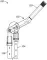
- FIG. 1illustrates a perspective view of a lever reducer system according to an embodiment.
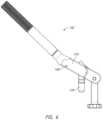
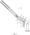
- FIG. 2illustrates a perspective view of a lever reducer of FIG. 1 .
- FIG. 3illustrates a top view of the lever reducer of FIG. 1 .
- FIG. 4illustrates a bottom view of the lever reducer of FIG. 1 .
- FIG. 5illustrates a front view of the lever reducer of FIG. 1 .
- FIG. 6illustrates a first side view of the lever reducer of FIG. 1 .
- FIG. 7illustrates a cross-sectional view of the lever reducer of FIG. 1 .
- FIG. 8illustrates a fulcrum of the lever reducer of FIG. 1 .
- FIG. 9illustrates a second side view of the lever reducer of FIG. 1 .
- FIG. 10illustrates a cross-sectional view of the lever reducer of FIG. 1 .
- FIG. 11illustrates an actuator of the lever reducer of FIG. 1 .
- FIG. 12illustrates a first tower of the lever reducer system of FIG. 1 .
- FIG. 13illustrates exploded components of the lever reducer system of FIG. 1 .
- FIG. 14illustrates the first tower and a second tower of the lever reducer system of FIG. 1 .
- FIGS. 15 A- 15 Fillustrate movement of the lever reducer system of FIG. 1 .
- FIG. 1illustrates a perspective view of an embodiment of a lever reducer system 100 .
- the lever reducer system 100can include a lever reducer 102 .
- the lever reducer 102can be utilized to move one component into an adjacent position to another component as described herein.
- the lever reducer 102can be reversibly coupled to other components of the lever reducer system 100 .
- the lever reducer 102can provide leverage to a user to vertically lift a vertebra.
- the lever reducer 102can facilitate rod reduction by moving a fastener into alignment with a rod.
- the lever reducer 102can have many uses and advantages, as described herein.
- the lever reducer system 100can include a first tower 104 .
- the first tower 104can be any elongate structure.
- the first tower 104can be a component of a tower based screw system.
- the first tower 104can be a component of an extended tab screw system.
- the first tower 104can be a component of a tower-based screw system or the extended tabs on minimally invasive pedicle screws with breakoff tabs.
- the first tower 104can provide access through the skin and tissue of the patient toward a first vertebra.
- the first tower 104can be coupled to the lever reducer 102 .
- the lever reducer system 100can include a first fastener 106 .
- the first fastener 106can be coupled to any portion of the spine.
- the first fastener 106can be coupled to the first vertebra.
- the first fastener 106can have any form or function to engage the vertebra.
- the first fastener 106can couple to a pedicle.
- the first fastener 106can be a polyaxial screw.
- the first tower 104can couple to the first fastener 106 .
- the first tower 104can couple to a head of the first fastener 106 .
- the first tower 104is a separate component from the first fastener 106 .
- the first tower 104can easily couple and decouple from the first fastener 106 .
- the first tower 104can include a locking feature to ensure attachment to the first fastener 106 .
- the first tower 104is a breakaway tower.
- the first tower 104is integrated with the corresponding first fastener 106 .
- the first tower 104 and the head of the first fastener 106can be unitarily formed.
- the first tower 104 and the head of the first fastener 106can include a score line therebetween.
- the first tower 104can easily and cleanly break away at the score line, leaving the head of the first fastener 106 anchored to the first vertebra.
- the first tower 104can include extended tabs from the head of the first fastener 106 .
- the extended tabscan be removed in a single motion by applying a force to the extended tabs.
- the first fastener 106can be a minimally invasive pedicle screw.
- the first tower 104can be breakoff extended tabs. The first tower 104 can provide access to the first fastener 106 .
- the lever reducer system 100can include a second tower 108 .
- the first tower 104 and the second tower 108can be identical.
- the second tower 108can be any elongate structure.
- the second tower 108can be a component of a tower based screw system.
- the second tower 108can be a component of an extended tab screw system.
- the second tower 108can be a component of a tower-based screw system or the extended tabs on minimally invasive pedicle screws with breakoff tabs.
- the second tower 108can provide access through the skin and tissue of the patient toward a second vertebra.
- the second tower 108can be coupled to the lever reducer 102 .
- the second tower 108can be lifted by the lever reducer 102 , as described herein.
- the lever reducer system 100can include a second fastener 110 .
- the first fastener 106 and the second fastener 110can be identical.
- the second fastener 110can be coupled to any portion of the spine.
- the second fastener 110can be coupled to the second vertebra.
- the second fastener 110can have any form or function to engage the vertebra.
- the second fastener 110can couple to a pedicle.
- the second fastener 110can be a polyaxial screw.
- the second tower 108can couple to the second fastener 110 .
- the second tower 108can couple to a head of the second fastener 110 .
- the second tower 108is a separate component from the second fastener 110 .
- the second tower 108can easily couple and decouple from the second fastener 110 .
- the second tower 108can include a locking feature to ensure attachment to the second fastener 110 .
- the second tower 108is a breakaway tower.
- the second tower 108is integrated with the corresponding second fastener 110 .
- the second tower 108 and the head of the second fastener 110can be unitarily formed.
- the second tower 108 and the head of the second fastener 110can include a score line therebetween.
- the second tower 108can easily and cleanly break away at the score line, leaving the head of the second fastener 110 anchored to the second vertebra.
- the second tower 108can include extended tabs from the head of the second fastener 110 .
- the extended tabscan be removed in a single motion by applying a force to the extended tabs.
- the second fastener 110can be a minimally invasive pedicle screw.
- the second tower 108can be breakoff extended tabs.
- the second tower 108can provide access to the second fastener 110 .
- the lever reducer system 100can include a rod 112 .
- the rod 112can be curved.
- the rod 112can laterally extend through the first tower 104 .
- the rod 112can laterally extend through the second tower 108 .
- the rod 112can slide relative to the towers 104 , 108 and toward the vertebrae.
- the rod 112can be seated within the head of the first fastener 106 .
- the rod 112can be secured by a cap to the first fastener 106 .
- the rod 112can be located within the second tower 108 when the rod 112 is secured to the first fastener 106 .
- the rod 112can be vertically above the head of the second fastener 110 .
- the rod 112cannot be secured to the second fastener 110 due to the position of the second fastener 110 .
- the rod 112cannot be secured to the second fastener 110 due to the position of the second vertebra.
- the lever reducer 102can lift the second tower 108 .
- the lever reducer 102can lift the second fastener 110 .
- the lever reducer 102can lift the second vertebra.
- the lever reducer 102can raise the second fastener 110 such that the rod 112 can be seated within the head of the second fastener 110 .
- the lever reducer 102can raise the second vertebra toward a natural curvature.
- the lever reducer 102can raise the second vertebra to correct spondylolisthesis or slippage of the second vertebra.
- the lever reducer 102can raise the second vertebra to reduce compression of the spinal nerves.
- the lever reducer 102can raise the second vertebra into alignment with the first vertebra.
- the first vertebra and the second vertebracan be any adjacent vertebrae. In some methods, the first vertebra and the second vertebra are not adjacent vertebrae and have one or more intermediate vertebra therebetween.
- the first vertebra and the second vertebracan be lumbar vertebrae. In some methods, the first vertebra and the second vertebra can be the L5 and L4 vertebra, respectively. In some methods, the first vertebra and the second vertebra can be the L4 and L5 vertebra, respectively. In some methods, the first vertebra is superior to the second vertebra. In some methods, the first vertebra is inferior to the second vertebra. In some methods, the first vertebra and the second vertebra can be the S1 and L5 vertebra, respectively.
- the first tower 104is coupled to the sacrum. In some methods, the first fastener 106 is coupled to the sacrum. In some methods, the second tower 108 is coupled to L5. In some methods, the second fastener 110 is coupled to L5. The lumbar vertebra L5 can be lifted relative to the sacrum. In some methods, the first vertebra and the second vertebra can be the L5 and S1 vertebra, respectively. In some methods, the first tower 104 is coupled to L5. In some methods, the first fastener 106 is coupled to L5. In some methods, the second tower 108 is coupled to the sacrum. In some methods, the second fastener 110 is coupled to the sacrum. The sacrum can be lifted relative to the lumbar vertebra L5. The first tower 104 and the first fastener 106 can be coupled to any portion of the spine. The second tower 108 and the second fastener 110 can be coupled to any portion of the spine.
- the lever reducer system 100 described hereincan be located at any level of the vertebral column.
- the fasteners 106 , 110can be secured to any vertebrae.
- the rod 112can be positioned between any vertebrae. In the description herein, the rod 112 is described as positioned between the first vertebra and the second vertebra. It should be appreciated that the lever reducer system 100 can be utilized in any portion of the spine.
- the desired orientation of the rod 112can depend on the first vertebra and the second vertebra.
- the rod 112can restore a natural curvature of the spine.
- the rod 112can provide a correction in one or more planes.
- the rod 112can fuse the first vertebra and the second vertebra.
- the rod 112can be placed at any angle to the transverse plane, including parallel, substantially parallel, perpendicular, substantially perpendicular, 0 degrees, 15 degrees, 30 degrees, 45 degrees, 60 degrees, 75 degrees, 90 degrees, or any range of two of the foregoing values.
- the rodcan be placed at any angle to the sagittal plane, including parallel, substantially parallel, perpendicular, substantially perpendicular, 0 degrees, 15 degrees, 30 degrees, 45 degrees, 60 degrees, 75 degrees, 90 degrees, or any range of two of the foregoing values.
- the rodcan be placed at any angle to the coronal plane, including parallel, substantially parallel, perpendicular, substantially perpendicular, 0 degrees, 15 degrees, 30 degrees, 45 degrees, 60 degrees, 75 degrees, 90 degrees, or any range of two of the foregoing values.
- the lever reducer system 100can facilitate placement of the rod 112 relative to the fasteners 106 , 110 by moving one component into an adjacent position to another component.
- the lever reducer system 100can facilitate placement of the rod 112 relative to the fasteners 106 , 110 by moving the second vertebra with the second fastener 110 into an adjacent position relative to the first vertebra with the first fastener 106 .
- the lever reducer system 100can facilitate placement of the rod 112 by raising the second fastener 110 to be able to seat the rod 112 within the head of the second fastener 110 .
- FIG. 2illustrates a perspective view of the lever reducer 102 .
- FIG. 3illustrates a top view of the lever reducer 102 .
- FIG. 4illustrates a bottom view of the lever reducer 102 .
- FIG. 5illustrates a front view of the lever reducer 102 .
- the lever reducer 102can include a handle 120 .
- the handle 120can include a grip 122 .
- the grip 122can be a knurled surface.
- the grip 122can be a textured surface.
- the grip 122can have any feature to facilitate manipulation by a user.
- the handle 120can be removable.
- the handle 120can include a threaded tip.
- the handle 120can couple to a base 124 .
- the base 124can include a threaded bore to engage the threaded tip of the handle 120 .
- the base 124includes a threaded tip and the handle 120 includes a threaded bore.
- the handle 120 and the base 124are integrally or monolithically formed.
- the handle 120can be angled relative to the base 124 .
- the handle 120can form an angle relative to the base 124 of 0 degrees, 5 degrees, 10 degrees, 15 degrees, 20 degrees, 25 degrees, 30 degrees, 35 degrees, 40 degrees, 45 degrees, 50 degrees, 55 degrees, 60 degrees, 65 degrees, 70 degrees, 75 degrees, 80 degrees, 85 degrees, 90 degrees, between 0 degrees and 20 degrees, between 10 degrees and 30 degrees, less than 45 degrees, less than 60 degrees, or any range of two of the foregoing values.
- the lever reducer 102can include a fulcrum 130 .
- the lever reducer 102can include a first engagement feature 132 .
- the base 124can include the first engagement feature 132 .
- the first engagement feature 132can include a main translational channel 160 .
- the first engagement feature 132can allow the fulcrum 130 to translate relative to the base 124 .
- the first engagement feature 132can allow the fulcrum 130 to translate linearly.
- the first engagement feature 132can allow the fulcrum 130 to translate a distance relative to the base 124 .
- the fulcrum 130can translate relative to the base 124 a distance of 0 mm, 1 mm, 2 mm, 3 mm, 4 mm, 5 mm, 6 mm, 7 mm, 8 mm, 9 mm, 10 mm, 11 mm, 12 mm, 13 mm, 14 mm, 15 mm, 16 mm, 17 mm, 18 mm, 19 mm, 20 mm, 21 mm, 22 mm, 23 mm, 24 mm, 25 mm, 26 mm, 27 mm, 28 mm, 29 mm, 30 mm, between 5 mm and 15 mm, between 10 mm and 20 mm, between 15 mm and 30 mm, up to 10 mm, up to 15 mm, or any range of two of the foregoing values.
- the first engagement feature 132can allow the fulcrum 130 to rotate relative to the base 124 .
- the first engagement feature 132can allow the fulcrum 130 to rotate and translate simultaneously.
- the first engagement feature 132can allow the fulcrum 130 to rotate without translation.
- the fulcrum 130can rotate relative to the base 124 to form an angle of 0 degrees, 5 degrees, 10 degrees, 15 degrees, 20 degrees, 25 degrees, 30 degrees, 35 degrees, 40 degrees, 45 degrees, 50 degrees, 55 degrees, 60 degrees, 65 degrees, 70 degrees, 75 degrees, 80 degrees, 85 degrees, 90 degrees, 95 degrees, 100 degrees, 105 degrees, 110 degrees, 115 degrees, 120 degrees, between 45 degrees and 90 degrees, between 30 degrees and 120 degrees, greater than 45 degrees, greater than 60 degrees, or any range of two of the foregoing values.
- the fulcrum 130can rotate relative to the base 124 a greater degree in a distal position of the fulcrum 130 .
- the base 124can include a recess 134 .
- the recess 134can allow the fulcrum 130 to rotate relative to the base 124 to form an angle of 90 degrees, 95 degrees, 100 degrees, 105 degrees, 110 degrees, 115 degrees, 120 degrees, 130 degrees, 135 degrees, 140 degrees, 145 degrees, 150 degrees, 155 degrees, 160 degrees, 165 degrees, 170 degrees, 175 degrees, 180 degrees, 185 degrees, 190 degrees, 195 degrees, 200 degrees, 205 degrees, 210 degrees, 215 degrees, 220 degrees, 230 degrees, 235 degrees, 240 degrees, 245 degrees, 250 degrees, 255 degrees, 260 degrees, 265 degrees, 270 degrees, between 180 degrees and 270 degrees, between 90 degrees and 180 degrees, greater than 90 degrees, greater than 120 degrees, or any range of two of the foregoing values.
- the fulcrum 130can include a bearing surface 136 .
- the bearing surface 136can rest against the first tower 104 .
- the bearing surface 136can include one or more ridges.
- the bearing surface 136can be continuous around the fulcrum 130 .
- the bearing surface 136can be a ring.
- the bearing surface 136can be discontinuous around the fulcrum 130 .
- the bearing surface 136can be a pair of tabs.
- the bearing surface 136can be two diametrically opposed tabs.
- the fulcrum 130can include an insertion surface 138 .
- the insertion surface 138can be below the bearing surface 136 .
- the insertion surface 138can be inserted into the first tower 104 .
- the distal end of the fulcrum 130can be tapered to facilitate insertion into the first tower 104 .
- the insertion surface 138can have a tapered end.
- the insertion surface 138can be cylindrical.
- the insertion surface 138can be the same or similar cross-section as a cross-section of a lumen of the first tower 104 .
- the insertion surface 138can have circular or rounded cross-section.
- the fulcrum 130can rotate within the first tower 104 .
- the fulcrum 130can have an infinite number of rotational orientations relative to the first tower 104 .
- the insertion surface 138can have non-circular cross-section.
- the insertion surface 138can have a keyed cross-section.
- the fulcrum 130cannot rotate within the first tower 104 .
- the fulcrum 130can have a discrete number of rotational orientations relative to the first tower 104 .
- the fulcrum 130can have one rotational orientation relative to the first tower 104 .
- the lever reducer 102can include a swivel 140 .
- the lever reducer 102can include a second engagement feature 142 .
- the second engagement feature 142can be ratchet mechanism.
- the second engagement feature 142can include an actuator 144 .
- the second engagement feature 142can include a pin 146 .
- the actuator 144 and the pin 146can couple to the base 124 .
- the second engagement feature 142can allow the swivel 140 to rotate relative to the base 124 .
- the second engagement feature 142can prevent the swivel 140 from translating.
- the second engagement feature 142can maintain the rotational position of the swivel 140 .
- the second engagement feature 142can allow rotational motion of the swivel 140 in a first direction.
- the second engagement feature 142can prevent rotational motion of the swivel 140 in a second direction, opposite the first direction.
- the second engagement feature 142can allow clockwise rotation of the swivel 140 but prevent counterclockwise rotation of the swivel 140 .
- the second engagement feature 142can maintain a rotational position of the swivel 140 .
- the second engagement feature 142can allow the swivel 140 to rotate without translation.
- the swivel 140can rotate relative to the base 124 to form an angle of 0 degrees, 5 degrees, 10 degrees, 15 degrees, 20 degrees, 25 degrees, 30 degrees, 35 degrees, 40 degrees, 45 degrees, 50 degrees, 55 degrees, 60 degrees, 65 degrees, 70 degrees, 75 degrees, 80 degrees, 85 degrees, 90 degrees, 95 degrees, 100 degrees, 105 degrees, 110 degrees, 115 degrees, 120 degrees, between 45 degrees and 90 degrees, between 30 degrees and 120 degrees, greater than 45 degrees, greater than 60 degrees, or any range of two of the foregoing values.
- the second engagement feature 142can allow the swivel 140 to travel in an arc.
- the swivel 140can include a gripping surface 148 .
- the gripping surface 148can be inserted around the second tower 108 .
- the second tower 108can include a keyed surface.
- the second tower 108can have a polygonal surface including two flats, three flats, four flats, five flats, six flats, seven flats, eight flats, nine flats, ten flats, eleven flats, twelve flats, between six flats and eight flats, or any range of two of the foregoing values.
- the gripping surface 148can have a keyed socket.
- the gripping surface 148can have a polygonal surface including two flats, three flats, four flats, five flats, six flats, seven flats, eight flats, between two flats and four flats, or any range of two of the foregoing values.
- the gripping surface 148can have the form of an open-end wrench.
- the gripping surface 148can be the same or similar cross-section as a cross-section of the second tower 108 .
- the gripping surface 148can have non-circular cross-section.
- the gripping surface 148can have a keyed cross-section. In some embodiments, the gripping surface 148 cannot rotate relative to the second tower 108 .
- the gripping surface 148can have a discrete number of rotational orientations relative to the second tower 108 .
- the gripping surface 148can have one rotational orientation relative to the second tower 108 .
- the gripping surface 148can have circular or rounded cross-section.
- the gripping surface 148can rotate relative to the second tower 108 .
- the gripping surface 148can have an infinite number of rotational orientations relative to the second tower 108 .
- the swivel 140can have an L-shape geometry.
- the swivel 140can have an extension 150 .
- the extension 150can align with the actuator 144 .
- the gripping surface 148can be laterally offset.
- the gripping surface 148can be offset from the actuator 144 .
- the gripping surface 148can be perpendicular to the extension 150 .
- the lever reducer 102can have features aligned generally along a longitudinal axis of the lever reducer 102 that facilitate the application of a force.
- the handle 120can be aligned with the first engagement feature 132 .
- the handle 120can be aligned with the fulcrum 130 . This alignment can prevent a torque on the fulcrum 130 when a force is applied to the handle 120 .
- the handle 120can be aligned with the first tower 104 . This alignment can prevent a torque on the first tower 104 when a force is applied to the handle 120 .
- the handle 120can be aligned with the second tower 108 .
- This alignmentcan prevent a torque on the second tower 108 when a force is applied to the handle 120 .
- the first tower 104 and the second tower 108can be aligned with each other.
- the shape of the swivel 140can position the second tower 108 to be aligned with the first tower 104 .
- the first tower 104 and the second tower 108can be aligned with the fulcrum 130 .
- the fulcrum 130is the support about which the lever reducer 102 pivots, as described herein.
- the handle 120can be aligned with the fulcrum 130 .
- the handle 120 and the base 124act as a lever to pivot about the fulcrum 130 .
- the handle 120 and the base 124are a rigid body which pivots. As the handle 120 and a portion of the base 124 proximal to the fulcrum 130 are lowered, the portion of the base 124 distal to the fulcrum 130 raises.
- the lever reducer 102can include the first engagement feature 132 and the second engagement feature 142 which facilitate this pivoting.
- the first engagement feature 132can allow rotation and translation of the fulcrum 130 .
- the fulcrum 130is a movable pivot.
- the second engagement feature 142can allow rotation of the swivel 140 .
- the swivel 140allows rotation in a first direction but prevents or limits rotation in a second direction, opposite the first direction. Additional features of the first engagement feature 132 and the second engagement feature 142 are described herein.
- FIG. 6illustrates a first side view of the lever reducer 102 .
- FIG. 7illustrates a cross-sectional view of the lever reducer 102 .
- FIG. 8illustrates the fulcrum 130 of the lever reducer 102 .
- the first engagement feature 132can include the main translational channel 160 .
- the main translational channel 160can be linear.
- the main translational channel 160can be non-linear.
- the main translational channel 160can form an arc.
- the first engagement feature 132can include a pair of side channels 162 .
- the side channels 162can extend along sides of the main translational channel 160 .
- the side channels 162can extend the entire length of the main translational channel 160 .
- the side channels 162can extend along a portion of the length of the main translational channel 160 .
- the first engagement feature 132can include a pair of flanges 164 .
- the pair of flanges 164can extend along sides of the main translational channel 160 .
- the pair of flanges 164can extend under the side channels 162 .
- the pair of flanges 164can extend the entire length of the main translational channel 160 .
- the pair of flanges 164can extend along a portion of the
- the fulcrum 130can include a pair of pivots 166 .
- the pair of pivots 166can be axially aligned.
- the pair of pivots 166can be diametrically opposed.
- the pair of pivots 166can form a pivot pin.
- the fulcrum 130 and the pair of pivots 166can be integrally or monolithically formed.
- the fulcrum 130can include a bore configured to receive a pivot pin.
- the fulcrum 130 and the pair of pivots 166 or other pivot pincan be separately formed.
- the pair of pivots 166can be cylindrical.
- the pair of pivots 166can include rounded edges.
- the pair of pivots 166can be semi-spherical.
- the pair of pivots 166extend into the pair of side channels 162 of the base 124 . Each pivot 166 slides along the side channels 162 as the fulcrum 130 slides. Each pivot 166 is retained within the side channel 162 by the flange 164 as the fulcrum 130 slides. Each pivot 166 slides along the flange 164 .
- the bearing surface 136 and the insertion surface 138extend from the main translational channel 160 as the fulcrum 130 slides.
- the fulcrum 130freely translates proximally and distally as the pair of pivots 166 is retained in the side channels 162 .
- the pair of pivots 166can rotate within the pair of side channels 162 . Each pivot 166 is retained within the side channel 162 by the flange 164 as the fulcrum 130 rotates. Each pivot 166 rotates relative to the flange 164 .
- the shape of the pair of pivots 166can facilitate rotation.
- the fulcrum 130can rotate relative to the base 124 .
- the fulcrum 130can translate relative to the base 124 .
- the fulcrum 130can rotate and translate relative to the base 124 .
- the pair of pivots 166can translate within the first engagement feature 132 in discrete steps.
- the first engagement feature 132can include one or more locking grooves that provide discrete translational positions.
- the first engagement feature 132can include two locking grooves, three locking grooves, four locking grooves, five locking grooves, six locking grooves, seven locking grooves, eight locking grooves, nine locking grooves, ten locking grooves, or any range of two of the foregoing values.
- the first engagement feature 132can include any number of locking grooves.
- the locking groovescan be formed in the pair of flanges 164 .
- the locking groovescan be formed in the pair of side channels 162 .
- the locking groovescan be formed in the main translational channel 160 .
- the locking groovescan be separately formed from the components of the first engagement feature 132 .
- the locking groovescan interact with the pair of pivots 166 of the fulcrum 130 .
- the pair of pivots 166can slide distally and proximally to engage the next locking groove.
- the locking groovecan apply a frictional force to retain the pair of pivots 166 .
- the pair of pivots 166can overcome the frictional force by a force applied by the user.
- the pair of pivots 166can overcome the frictional force by movement of one component relative to another.
- the fulcrum 130can include the bearing surface 136 configured to rest against the first tower 104 .
- the bearing surface 136can include a pair of tabs.
- the pair of pivots 166can be above the bearing surface 136 .
- the pair of pivots 166can be aligned with the pair of tabs of the bearing surface 136 .
- the pair of pivots 166 and the bearing surface 136can prevent or limit a left-right rocking motion of the fulcrum 130 .
- the insertion surface 138can prevent or limit a left-right rocking motion of the fulcrum 130 .
- the pair of pivots 166 and the pair of side channels 162can limit the motion of the fulcrum 130 to proximal-distal translation within the main translational channel 160 .
- the pair of pivots 166 and the side channels 162can limit the motion of the fulcrum 130 to rotation within the main translational channel 160 .
- the rotationcan be swinging in the proximal-distal direction.
- the shape of the fulcrum 130can limit or reduce any other motion between the base 124 and the fulcrum 130 .
- the lever reducer 102can include a retention pin 168 .
- the retention pin 168can prevent disengagement between the fulcrum 130 and the base 124 .
- the retention pin 168can function as a proximal stop for the translation of the fulcrum 130 .
- the retention pin 168can be inserted after the pair of pivots 166 are inserted within the pair of side channels 162 .
- FIG. 9illustrates a second side view of the lever reducer 102 .
- FIG. 10illustrates a cross-sectional view of the lever reducer 102 .
- FIG. 11illustrates the actuator 144 of the lever reducer 102 .
- the second engagement feature 142can include the actuator 144 .
- the actuator 144can be actuated by the user.
- the actuator 144can be automatically actuated.
- the actuator 144can include a lever arm 170 .
- the lever arm 170can be biased.
- the actuator 144can include a spring 172 .
- the actuator 144can include a pivot pin 174 .
- the lever arm 170can pivot relative to the pivot pin 174 .
- the pivot pin 174can couple the lever arm 170 to the base 124 .
- the spring 172can be compressed.
- the lever arm 170can include a pawl 176 .
- the pawl 176can function as a ratchet.
- the swivel 140can include one or more gears 178 .
- the gears 178can be radial gears.
- the gears 178can be ramped.
- the gears 178can form a wedge.
- the gears 178can be asymmetric.
- the gears 178can allow movement in one direction but prevent movement in another direction.
- the gears 178can allow the pawl 176 to slide along the ramped surface of the gears 178 and into the next gear.
- the gears 178can prevent the pawl 176 from moving in the opposite direction.
- the ramped surface of the gears 178forms a wall or wedge to prevent movement of the pawl 176 in the opposite direction.
- the second engagement feature 142can include the pin 146 .
- the pin 146can couple the swivel 140 to the base 124 .
- the swivel 140can rotate relative to the base 124 .
- the swivel 140can rotate in a first direction.
- the pawl 176slides along a gear 178 thereby depressing the spring 172 .
- the pawl 176slides along a gear 178 until falling to the next gear 178 .
- the spring 172biases the lever arm 170 down into engagement with the groove of the gear 178 .
- the pawl 176slides along the next gear 178 thereby depressing the spring 172 .
- the pawl 176slides along a gear 178 until falling to the next gear 178 .
- the pawl 176freely advances in a first direction.
- the pawl 176can be limited or prevented from advancing in the opposite direction.
- the shape of the gears 178provide a wedge preventing rotational movement in the opposite direction.
- the pawl 176cannot vertically clear the wedge of the gear 178 .
- the spring 172biases the pawl 176 downward preventing rotational movement in the opposite direction.
- the second engagement feature 142can allow the swivel 140 to rotate relative to the base 124 in one direction.
- the second engagement feature 142provides a ratchet that limits rotational movement.
- the shape of the pawl 176 and the gears 178allows rotation in one direction, but limits rotation in the opposite direction.
- the biasing force of the spring 172allows rotation in one direction, but limits rotation in the opposite direction.
- the swivel 140rotates about the pin 146 relative to the base 124 .
- the swivel 140can form a slight arc during vertical motion as described herein.
- the second engagement feature 142can prevent the swivel 140 from translating relative to the base 124 .
- the second engagement feature 142can maintain the rotational position of the swivel 140 .
- the second engagement feature 142can maintain the correction between the first tower 104 and the second tower 108 .
- the second engagement feature 142can maintain the correction between the vertebrae as the second vertebra is lifted.
- the shape of the pawl 176 and the gears 178can maintain the rotation position during vertical lift.
- the biasing force of the spring 172can maintain the rotation position during vertical lift.
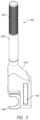
- FIG. 12illustrates the first tower 104 of the lever reducer system 100 .
- FIG. 13illustrates exploded components of the lever reducer system 100 .
- FIG. 14illustrates the first tower 104 and the second tower 108 of the lever reducer system 100 .
- the first tower 104 and the second tower 108facilitate placement of the rod 112 .
- the rod 112can be generally straight.
- the rod 112can include a bend.
- the bendcan correspond to a bend of the vertebrae.
- the bendcan correspond to a desired curvature of the spine.
- the bendcan correspond to a desired spinal correction.
- the bendcan correspond to a desired lift of the second vertebra.
- the first fastener 106is coupled to the first vertebra.
- the first vertebracan be any vertebra along the spine of the patient.
- the first fastener 106can include a threaded shaft 180 .
- the first fastener 106can be rotated to engage the first vertebra.
- the first fastener 106can be positioned to engage cortical bone.
- the first fastener 106engages the pedicle.
- the pedicleis a portion of the vertebra between the transverse process and the vertebral body.
- the pediclecan be used as an anchoring point for fasteners in spinal procedures.
- the first fastener 106engages another portion of the first vertebra.
- the first fastener 106can couple to the spinal process.
- the first fastener 106can couple to the transverse process.
- the first fastener 106can couple to the lamina.
- the first fastener 106can be coupled to any portion of the first vertebra.
- the first fastener 106can include a head 182 .
- the head 182can include a slot 184 sized and configured to receive the rod 112 .
- the head 182can have polyaxial movement relative to the threaded shaft 180 .
- the threaded shaft 180can have a bulbous surface 186 .
- the head 182can receive the bulbous surface 186 of the threaded shaft 180 .
- the head 182can move within a range of motion relative to the threaded shaft 180 .
- the head 182can rotate relative to the threaded shaft 180 .
- the head 182can tilt relative to the threaded shaft 180 .
- the polyaxial movement between the threaded shaft 180 and the head 182can facilitate a range of orientations for the first fastener 106 .
- the polyaxial movement between the threaded shaft 180 and the head 182can facilitate a range of orientations for the rod 112 .
- the head 182can have no movement relative to the threaded shaft 180 .
- the head 182can have only monoaxial movement relative to the threaded shaft 180 .
- the first tower 104can couple to the first fastener 106 .
- the first tower 104can couple to the first fastener 106 after the first fastener 106 is coupled to the first vertebra. In other methods, the first tower 104 can couple to the first fastener 106 before the first fastener 106 is coupled to the first vertebra.
- the first tower 104can couple to the head 182 .
- the head 182can include a pair of recesses 188 .
- the first tower 104can include a pair of arms 190 .
- the pair of arms 190can engage the pair of recesses 188 to couple the first tower 104 to the first fastener 106 .
- the pair of arms 190can be deflected radially outward to accommodate the head 182 therebetween.
- the pair of arms 190can be biased inward into engagement with the pair of recesses 188 .
- the first tower 104 and the head 182are integrally or monolithically formed. In some embodiments, the first tower 104 and the first fastener 106 are integrally or monolithically formed.
- the threaded shaft 180can have no movement relative to the combined head 182 and the tower 104 .
- the threaded shaft 180can have monoaxial movement relative to the combined head 182 and the tower 104 .
- the threaded shaft 180can have polyaxial movement relative to the combined head 182 and the tower 104 .
- the first tower 104can decouple from the first fastener 106 after the rod 112 is secured.
- the first tower 104can include a score line indicating that location of the decoupling.
- the first tower 104can include a shaft 192 .
- the shaft 192can include a slot 194 sized to receive the rod 112 .
- the rod 112can slide toward the first fastener 106 .
- the rod 112is inserted into the head 182 without sliding vertically in the slot 194 .
- the rod 112is inserted along a trajectory.
- the first tower 104can include a tower cap 196 .
- the tower cap 196can rotate relative to the shaft 192 .
- the tower cap 196can translate relative to the shaft 192 .
- the tower cap 196can rotate and translate to control the engagement of the pair of arms 190 with the pair of recesses 188 .
- the tower cap 196can rotate and translate to control the coupling of the first tower 104 and the first fastener 106 .
- the tower cap 196can rotate and translate to disengage the pair of arms 190 with the pair of recesses 188 .
- the tower cap 196can rotate and translate to control the decoupling of the first tower 104 and the first fastener 106 .
- the rod 112is seated within the first fastener 106 .
- the shaft 192 and the tower cap 196can form a lumen therethrough.
- the lumencan accommodate a threaded cap 198 .
- the threaded cap 198can be lowered toward the first fastener 106 .
- the threaded cap 198can couple to the first fastener 106 to retain the rod 112 .
- the threaded cap 198can couple the rod 112 to the first fastener 106 .
- the threaded cap 198can exert a force on the rod 112 to seat the rod 112 within the slot 184 of the head 182 .
- the threaded cap 198can exert a force on the rod 112 which can exert a force on the bulbous surface 186 .
- the threaded cap 198can exert a force on the rod 112 to prevent or limit the polyaxial movement of the threaded shaft 180 .
- the second fastener 110is coupled to the second vertebra.
- the second vertebracan be adjacent to the first vertebra.
- the second vertebracan be separated from the first vertebra by one or more intermediate vertebra.
- the second vertebracan be superior to the first vertebra.
- the second vertebracan be inferior to the first vertebra.
- the second vertebracan be any vertebra along the spine of the patient.
- the second fastener 110can include any feature of the first fastener 106 described herein.
- the second tower 108can couple to the second fastener 110 .
- the second tower 108can be integrally formed with the second fastener 110 .
- the second tower 108can include any of the features of the first tower 104 described herein.
- the rod 112can extend through the slot 194 sized to receive the rod 112 of the second tower 108 .
- the rod 112is vertically displaced relative to the head 182 of the second fastener 110 .
- the rod 112is not seated within the head 182 of the second fastener 110 .
- the rod 112can be vertically lifted a distance from the desired position within the head 182 of the second fastener 110 .
- the distancecan be 1 mm, 2 mm, 3 mm, 4 mm, 5 mm, 6 mm, 7 mm, 8 mm, 9 mm, 10 mm, 11 mm, 12 mm, 13 mm, 14 mm, 15 mm, 16 mm, 17 mm, 18 mm, 19 mm, 20 mm, 21 mm, 22 mm, 23 mm, 24 mm, 25 mm, 26 mm, 27 mm, 28 mm, 29 mm, 30 mm, between 5 mm and 20 mm, between 10 mm and 30 mm, at least 5 mm, at least 10 mm, or any range of two of the foregoing values.
- the rod 112is within the slot 184 of the head 182 when properly seated.
- the rod 112exerts a force on the bulbous surface 186 when properly seated.
- the rod 112can be secured by the threaded cap 198 when properly seated.
- the lever reducer 102can be utilized to change the position of the second tower 108 .
- the lever reducer 102can be utilized to change the position of the second fastener 110 .
- the lever reducer 102can be utilized to change the position of the second vertebra. In some methods, the lever reducer 102 does not change the position of the first tower 104 , the first fastener 106 , or the first vertebra. In some methods, the lever reducer 102 does not change the position of the rod 112 .
- the rod 112is not seated within the first fastener 106 before use of the lever reducer 102 .
- the first fastener 106can be coupled to the first vertebra.
- the second fastener 110can be coupled to the second vertebra. If separate components, the first tower 104 can couple to the first fastener 106 . If separate components, the second tower 108 can couple to the second fastener 110 .
- the towers 104 , 108can be components of a tower-based screw system. If integrated components, the first fastener 106 and the first tower 104 are coupled to the first vertebra. If integrated components, the second fastener 110 and the second tower 108 are coupled to the second vertebra.
- the towers 104 , 108can be extended tabs.
- the towers 104 , 108can be integrated tabs on the fasteners 108 , 110 .
- the fasteners 108 , 110 and the towers 104 , 108can be minimally invasive pedicle screws with breakoff tabs.
- the rod 112is not positioned relative to the first fastener 106 before use of the lever reducer 102 .
- the threaded cap 198is not positioned relative to the first fastener 106 before use of the lever reducer 102 .
- the rod 112is not retained relative to the first fastener 106 .
- the lever reducer 102can be utilized without the rod 112 in position.
- the lever reducer 102can lift the second tower 108 relative to the first tower 104 .
- the lever reducer 102can be utilized prior to introduction of the rod 112 .
- the lever reducer 102can be used to lift the second tower 108 to align the first tower 104 and the second tower 108 prior to introduction of the rod 112 .
- the lever reducer 102can be used to lift the head 182 of the second fastener 110 .
- the head of the second fastener 110 and the head of the first fastener 106can be aligned prior to introduction of the rod 112 .
- the lever reducer 102can change the vertical displacement of the second fastener 110 to allow introduction of the rod 112 therethrough.
- the rod 112can be lowered after use of the lever reducer 102 .
- the rod 112can be lowered along the first tower 104 .
- the rod 112can be lowered along the second tower 108 .
- the rod 112can be lowered along the first tower 104 and the second tower 108 simultaneously.
- the rod 112can be seated within the first fastener 106 .
- the rod 112can be seated within the second fastener 110 .
- the rod 112can be seated within the first fastener 106 and seated within the second fastener 110 simultaneously.
- the rod 112can be seated within the first fastener 106 and seated within the second fastener 110 sequentially.
- the rod 112can be seated within the fasteners 106 , 110 by lowering the rod 112 along the towers 104 , 108 .
- the rod 112can be seated within the fasteners 106 , 110 without lowering the rod 112 along the towers 104 , 108 .
- the rod 112can be introduced after the second tower 108 is vertically lifted.
- the rod 112can be secured to the second fastener 110 while the lever reducer 102 is in use.
- the threaded cap 198can secure the rod 112 to the second fastener 110 .
- the lever reducer 102can be removed.
- the rod 112can be secured to the first fastener 106 after the lever reducer 102 is removed.
- the threaded cap 198can secure the rod 112 to the first fastener 106 .
- FIGS. 15 A- 15 Fillustrate movement of the lever reducer system 100 .
- FIG. 15 Aillustrates an initial position of the lever reducer system 100 according to some methods.
- FIGS. 15 B- 15 Eillustrate intermediate positions of the lever reducer system 100 as the handle 120 is lowered according to some methods.
- FIG. 15 Fillustrates a final position of the lever reducer system 100 according to some methods.
- the first fastener 106is secured to the first vertebra.
- the second fastener 110is secured to the second vertebra.
- the fasteners 106 , 110can be secured in any order.
- the fasteners 106 , 110can be secured in series or simultaneously.
- the fasteners 106 , 110can allow for polyaxial movement that accommodates varying anatomical situations.
- the fasteners 106 , 110are coupled to the respective pedicles of the first vertebra and the second vertebra.
- the first tower 104can be secured to the first fastener 106 if separate components.
- the second tower 108can be secured to the second fastener 110 if separate components.
- the towers 104 , 108can be secured in any order.
- the towers 104 , 108can be secured in series or simultaneously.
- the towers 104 , 108can be secured to the fasteners 106 , 110 before securing the fasteners to the vertebrae.
- the towers 104 , 108can be secured to the fasteners 106 , 110 after securing the fasteners to the vertebrae.
- the towers 104 , 108 and the fasteners 106 , 110are integrally formed.
- the rod 112can be positioned relative to the slot 194 in the first tower 104 .
- the rod 112can be positioned relative to the slot 194 in the second tower 108 .
- the rod 112can be seated within the first fastener 106 .
- the rod 112can extend to the second tower 108 .
- the threaded cap 198can be lowered down the first tower 104 to the first fastener 106 .
- the rod 112can be secured to the first fastener 106 .
- the rod 112is secured to the first fastener 106 before use of the lever reducer 102 .
- the threaded cap 198is secured to the first fastener 106 before use of the lever reducer 102 .
- the rod 112is coupled to the first fastener 106 .
- the rod 112extends through the second tower 108 .
- the rod 112can be vertically offset relative to the second fastener 110 preventing coupling of the rod 112 to the second fastener 110 .
- the rod 112cannot be secured to the second fastener 110 due to the position of the relative components.
- the first vertebrais the L5 vertebra.
- the second vertebrais the L4 vertebra.
- the first vertebrais the L4 vertebra.
- the second vertebrais the L5 vertebra,
- the L5 vertebrais disposed between the L4 vertebra and the sacrum.
- the first vertebrais the S1 vertebra.
- the second vertebrais the L5 vertebra.
- the first vertebrais the L5 vertebra.
- the second vertebrais the S1 vertebra.
- the first vertebrais any sacral vertebra.
- the second vertebrais any other vertebra.
- the first vertebrais any lumbar vertebra.
- the second vertebrais any other lumbar vertebra or any other vertebra.
- the first vertebrais any thoracic vertebra.
- the second vertebrais any other thoracic vertebra or any other vertebra.
- the first vertebrais any cervical vertebra.
- the second vertebrais any other cervical vertebra or any other vertebra.
- the first vertebracan be any vertebra along the length of the spine.
- the second vertebracan be any other vertebra along the length of the spine.
- the first vertebra and the second vertebracan be adjacent.
- the first vertebra and the second vertebracan be separated by one or more intermediate vertebra.
- the towers 104 , 108are coupled to the fasteners 106 , 110 . Movement of the second tower 108 causes corresponding movement of the second fastener 110 . Movement of the second tower 108 causes corresponding movement of the second vertebra.
- the rod 112can be secured to the first fastener 106 throughout movement of the second tower 108 and the second fastener 110 .
- the rod 112can be disposed within the second tower 108 throughout movement of the second tower 108 and the second fastener 110 .
- the second tower 108can slide relative to the rod 112 during movement of the second tower 108 and the second fastener 110 .
- the second fastener 110can be lifted toward the rod 112 during movement of the second tower 108 and the second fastener 110 .
- the rod 112is not secured to the first fastener 106 during use of the lever reducer 102 .
- the rod 112can be secured after the second tower 108 is lifted.
- the rod 112can be positioned relative to the aligned heads 182 of the fasteners 106 , 108 after the second tower 108 is lifted.
- the second vertebracan be misaligned relative to the spinal column.
- the second vertebracan be misaligned due to spondylolisthesis or slippage of the second vertebra.
- the second vertebracan be slipped relative to a natural curvature.
- the second vertebracan cause compression of the spinal nerves extending through the foramen.
- the second vertebracan cause pain due to nerve compression.
- the second vertebracan have a sagittal deformity.
- the second vertebracan have a coronal deformity.
- the second vertebracan have a transverse deformity.
- the second vertebracan be misaligned relative to the first vertebra due to a deformity or degenerative condition.
- the lever reducer 102can engage the first tower 104 .
- the fulcrum 130can be at least partially inserted into a lumen of the first tower 104 .
- the fulcrum 130can be inserted into the tower cap 196 of the first tower 104 .
- the threaded cap 198is inserted into the lumen of the first tower 104 .
- the threaded cap 198can be rotated to secure the rod 112 to the first fastener 106 .
- the fulcrum 130can utilize the same lumen as the threaded cap 198 .
- the lever reducer 102can engage the second tower 108 .
- the gripping surface 148can engage the second tower 108 .
- the gripping surface 148can grip a keyed surface below the tower cap 196 of the second tower 108 .
- the pawl 176can engage a gear 178 .
- the actuator 144can be biased by the spring 172 .
- the pawls 176can be seated in a groove between gears 178 . Movement in one direction is allowed by overcoming the biasing force of the spring 172 . Movement in the opposite direction is prevented due to the shape of the gears 178 .
- the pawl 176can maintain a rotational orientation between the towers 104 , 108 .
- the fulcrum 130can slide within the first engagement feature 132 .
- the first engagement feature 132can accommodate the relative spacing between the first tower 104 and the second tower 108 .
- the bearing surface 136 of the fulcrum 103can rest against the tower cap 196 .
- the insertion surface 138 of the fulcrumcan be inserted into the first tower 104 .
- the first engagement feature 132can allow the fulcrum 130 to translate relative to the base 124 .
- the fulcrum 130can include a pair of pivots 166 .
- the pair of pivots 166are retained within the side channel 162 as the fulcrum 130 slides in the main translational channel 160 .
- the fulcrum 130can be at any location along the main translational channel 160 .
- the fulcrum 130can be at a distal location.
- the fulcrum 130can be at a proximal location.
- the fulcrum 130can slide to accommodate the spacing between the first tower 104 and the second tower 108 .
- the fulcrum 130can slide to accommodate the spacing between the first vertebra and the second vertebra.
- the fulcrum 130can slide to accommodate the anatomy of the patient.
- the fulcrum 130is a slidable pivot.
- the fulcrum 130is a fixed pivot.
- the pair of pivots 166define the pivot point 200 of the lever reducer 102 .
- the pivot point 200is movable as the fulcrum 130 moves.
- the pivot point 200can slide relative to the base 124 .
- the pivot point 200can be at any position.
- the fulcrum 130can slide based on the orientation of the first tower 104 coupled to the first fastener 106 .
- the polyaxial orientation of the first fastener 106can be locked when the rod 112 is secured to the first fastener 106 .
- the threaded cap 198can lock the orientation of the first fastener 106 .
- the first tower 104can be locked relative to the first fastener 106 .
- the lever reducer 102can accommodate the fixed relationship between the first vertebra, the first fastener 106 , and the first tower 104 .
- the fulcrum 130can slide to accommodate the fixed orientation of the first tower 104 relative to the first vertebra.
- the first tower 104is fixed relative to the threaded shaft 180 of the first fastener 106 when the rod 112 is secured.
- the pivot point 200is movable to limit or prevent applying a force or torque to the threaded shaft 180 of the first fastener 106 .
- the pivot point 200can be aligned with the first vertebra.
- the orientation between the pivot point 200 , the first tower 104 , the first fastener 106 , and the first vertebracan be fixed.
- the base 124 of the lever reducer 102can translate relative to this pivot point 200 .
- the base 124 of the lever reducer 102can rotate relative to this pivot point 200 .
- the lever system 100can include a radial distance 202 .
- the radial distance 202can be defined between the pivot point 200 and the pin 146 .
- the pin 146can couple the swivel 140 to the base 124 .
- the radial distance 202is constant during movement of the second tower 108 .
- the radial distance 202defines an arc of movement of the swivel 140 .
- the radial distance 202varies during movement of the second tower 108 .
- the handle 120 and the base 124act as a lever relative to the pivot point 200 .
- the usercan grip the handle 120 .
- the usercan lower the handle 120 as shown in FIGS. 15 A- 15 B .
- the usercan apply a force to the handle 120 .
- the usercan apply a downward force.
- the lever reducer 102can amplify the input force of the user to a greater output force to lift the vertebra.
- the lever reducer 102can provide leverage to facilitate the vertical lift.
- the lever reducer 102can lift the swivel 140 coupled to the second vertebra.
- the swivel 140can move in an arc relative to the pivot point 200 .
- the swivel 140can move mostly vertically.
- the swivel 140can move slightly outward relative to the first tower 104 .
- the usercan continue to lower the handle 120 as shown in FIGS. 15 C- 15 E .
- the second tower 108can gradually lift.
- the second tower 108can lift relative to the first tower 104 .
- FIG. 15 Fillustrates a final position of the second tower 108 according to some methods.
- the first tower 104 and the second tower 108can have the same height.
- the second tower 108can be vertically lifted.
- the first tower 104 and the second tower 108can have different heights.
- the second tower 108can be vertically lifted less than the height of the first tower 104 .
- the second tower 108can be vertically lifted greater than the height of the first tower 104 .
- the second tower 108is gripped by the lever reducer 102 to not obstruct the lumen of the second tower 108 .
- the designallows clearance for an inserter for the threaded cap 198 to be placed in the second tower 108 .
- the second tower 108is the tower in which rod 112 is being reduced.
- the threaded cap 198can be inserted into the second tower 108 and locked to the second fastener 110 .
- the threaded cap 198can secure the rod 112 to the second fastener 110 .
- the threaded cap 198can limit or prevent polyaxial movement of the second fastener 110 .
- the threaded cap 198lock the correction before removing lever reducer 102 .
- a third fastener and a third towerare coupled to the first vertebra.
- the first fastener 106 and the first tower 104can be on one side of the first vertebra.
- the third fastener and the third towercan be coupled to the other side of the first vertebra.
- a fourth fastener and a fourth towerare coupled to the second vertebra.
- the second fastener 110 and the second tower 108can be on one side of the second vertebra.
- the fourth fastener and the fourth towercan be coupled to the other side of the second vertebra.
- the third tower and the fourth towercan be coupled to the lever reducer 102 .
- two lever reducers 102are utilized to lift the second vertebra.
- the third fastener and the fourth fastenercan have any features of the fasteners described herein.
- the third tower and the fourth towercan have any features of the towers described herein.
- the fasteners 106 , 110can be coupled to the rod 112 to maintain the correction.
- the lever reducer 102can be decoupled from the towers 104 , 108 .
- the towers 104 , 108can be decoupled from the fasteners 106 , 110 .
- the fasteners 106 , 110 and the towers 104 , 108are integrally formed.
- the towers 104 , 108can be snapped off from the respective fasteners.
- the lever reducer system 100can include several advantages.
- the lever reducer 102can easily couple to the towers 104 , 108 .
- the lever reducer 102can include a fulcrum 130 that can be at least partially inserted into the top of the first tower 104 .
- the fulcrum 130can include a bearing surface 136 that rests against the first tower 104 .
- the fulcrum 130can include a portion that is inserted into the first tower 104 .
- the fulcrum 130defines the pivot point 200 of the lever reducer system 100 .
- the lever reducer 102pivots relative to the fulcrum 130 .
- the lever reducer 102pivots relative to the first tower 104 .
- the first tower 104is not raised or lowered.
- the first tower 104remains stationary.
- the first fastener 106remains stationary.
- the first vertebraremains stationary.
- the pivot point 200is aligned with the first tower 104 , the first fastener 106
- the fulcrumcan include a pair of pivot pins 166 about which the handle 120 and the base 124 pivot. As the handle 120 is lowered, a distal portion of the base 124 is raised. The distal portion of the base 124 can include the swivel 140 . The swivel 140 can couple to the second tower 108 . The lever reducer 102 pivots relative to the fulcrum 130 to raise the second tower 108 . The second tower 108 moves with the distal portion of the base 124 of the lever reducer 102 .
- the second tower 108vertically lifts.
- the second fastener 110vertically lifts.
- the second vertebravertically lifts.
- the second tower 108moves in a slight arc relative to the first tower 104 .
- the slight arccan be beneficial for moving the second vertebra relative to the first vertebra.
- the slight arccan move the second vertebra away from the first vertebra.
- the slight arccan move the second tower 108 away from the first tower 104 .
- the slight arccan facilitate the alignment of anatomical structures.
- the slight arccan be beneficial over a lift that is only vertical.
- the slight arccan facilitate movement of the second vertebra relative to the first vertebra to avoid or limit interaction between bony prominences on the first vertebra and/or the second vertebra.
- the pin 146 of the swivel 140can define a hinge.
- the hingeis positioned relative to the fulcrum 130 to allow for mostly vertical lift of a vertebra.
- the hinge and the fulcrum 130can be separated by the radial distance 202 .
- the radial distance 202can be maintained as the second tower 108 lifts.
- the radial distance 202can allow a ratio of lateral displacement to vertical lift.
- the lateral displacementis small allowing for mostly vertically lift.
- the movement of the swivel 140 along the arccan allow for 1 mm lateral displacement relative to 3 mm vertical lift, 5 mm vertical lift, 7 mm vertical lift, 10 mm vertical lift, 12 mm vertical lift, 15 mm vertical lift, 17 mm vertical lift, 20 mm vertical lift, or 1 mm lateral displacement relative to any range of two of the foregoing values.
- the movement of the swivel 140 along the arccan allow for a lateral displacement from 1 mm to 5 mm and a vertical displacement from 3 mm to 30 mm.
- the movement of the swivel 140 along the arccan allow for a lateral displacement of 0 mm, 0.5 mm, 1 mm, 1.5 mm, 2 mm, 2.5 mm, 3 mm, 3.5 mm, 4 mm, 4.5 mm, 5 mm, between 1 mm and 2 mm, between 1 mm and 3 mm, between 1 mm and 4 mm, between 1 mm and 5 mm, greater than 1 mm, greater than 2 mm, less than 5 mm, less than 4 mm, or any range of two of the foregoing values.
- the movement of the swivel 140 along the arccan allow for a vertical displacement of 1 mm, 2 mm, 3 mm, 4 mm, 5 mm, 6 mm, 7 mm, 8 mm, 9 mm, 10 mm, 11 mm, 12 mm, 13 mm, 14 mm, 15 mm, 16 mm, 17 mm, 18 mm, 19 mm, 20 mm, 21 mm, 22 mm, 23 mm, 24 mm, 25 mm, 26 mm, 27 mm, 28 mm, 29 mm, 30 mm, between 5 mm and 10 mm, between 10 mm and 15 mm, between 15 mm and 20 mm, between 20 mm and 25 mm, between 25 mm and 30 mm, between 1 mm and 10 mm, between 10 mm and 20 mm, between 20 mm and 30 mm, or any range of two of the foregoing values.
- the fulcrum 130can translate in the main translational channel 160 within the base 124 .
- the fulcrum 130can translate to quickly accommodate different spans between towers 104 , 108 .
- the fulcrum 130can translate to quickly accommodate different offsets between vertebral bodies.
- the fulcrum 130can translate to allow the lever reducer 102 to be used for patients having different sized vertebra.
- the fulcrum 130can translate to allow the lever reducer 102 to be used at any level of the spine.
- the fulcrum 130can translate to allow the lever reducer 102 to be used to accommodate a variety of degenerative conditions of the vertebrae.
- the second engagement feature 142maintains correction during the reduction maneuver.
- the second engagement feature 142can include a ratchet mechanism with the pawl 176 .
- the pawl 176engages gears 178 .
- the pawl 176can be biased in between gears 178 in an initial position of the towers 104 , 108 .
- the pawl 176can allow movement in only one direction.
- the gears 178can allow movement in only one direction.
- the pawl 176can allow movement of the second tower 108 away from the first tower 104 .
- the pawl 176can allow the swivel 140 to follow the arc defined by the radial distance 202 .
- the pawl 176can prevent movement in another direction based on the shape of the gears 178 .
- the pawl 176can prevent movement of the second tower 108 in a direction opposite to the direction of vertical lift.
- the pawl 176can maintain a correction during vertical lift.
- the pawl 176can maintain the vertical lift of the second tower 108 .
- the ratchet mechanismcan maintain the vertical lift of the second tower 108 .
- the pawl 176can maintain a correction if the lever reducer 102 is at one or more intermediate positions.
- the pawl 176can be biased by the spring 172 acting on the lever arm 170 .
- the force of the spring 172can facilitate maintaining the correction at one or more intermediate positions.
- the force of the spring 172can facilitate maintaining the correction if force is no longer applied to the handle 120 .
- the lever reducer system 100can be designed to lock the rod 112 to the first fastener 106 before engagement of the lever reducer 102 . In some methods, the lever reducer system 100 can be designed to lock the rod 112 to the first fastener 106 after removal of the lever reducer 102 .
- the first tower 104can be aligned with the pivot point 200 during operation of the lever reducer 102 .
- the first fastener 106 and the first tower 104can be aligned with the pivot point 200 during operation of the lever reducer 102 .
- the lever reducer 102allows the threaded cap 198 to be inserted into the second tower 108 to secure the rod 112 to the second fastener 110 .
- the rod 112can be secured to the fasteners 106 , 110 before removing the lever reducer 102 from the towers 104 , 108 .
- the rod 112can be secured to the first fastener 106 before utilizing the lever reducer 102 .
- the rod 112can be secured to the second fastener 110 during use of the lever reducer 102 .
- the rod 112can be secured to the first fastener 106 after utilizing the lever reducer 102 .
Landscapes
- Health & Medical Sciences (AREA)
- Orthopedic Medicine & Surgery (AREA)
- Neurology (AREA)
- Life Sciences & Earth Sciences (AREA)
- Surgery (AREA)
- Heart & Thoracic Surgery (AREA)
- Engineering & Computer Science (AREA)
- Biomedical Technology (AREA)
- Nuclear Medicine, Radiotherapy & Molecular Imaging (AREA)
- Medical Informatics (AREA)
- Molecular Biology (AREA)
- Animal Behavior & Ethology (AREA)
- General Health & Medical Sciences (AREA)
- Public Health (AREA)
- Veterinary Medicine (AREA)
- Surgical Instruments (AREA)
Abstract
Description
Claims (22)
Priority Applications (2)
| Application Number | Priority Date | Filing Date | Title |
|---|---|---|---|
| US17/723,932US12324610B2 (en) | 2021-04-28 | 2022-04-19 | Lever reducer |
| US19/202,550US20250281206A1 (en) | 2021-04-28 | 2025-05-08 | Lever reducer |
Applications Claiming Priority (2)
| Application Number | Priority Date | Filing Date | Title |
|---|---|---|---|
| US202163180931P | 2021-04-28 | 2021-04-28 | |
| US17/723,932US12324610B2 (en) | 2021-04-28 | 2022-04-19 | Lever reducer |
Related Child Applications (1)
| Application Number | Title | Priority Date | Filing Date |
|---|---|---|---|
| US19/202,550ContinuationUS20250281206A1 (en) | 2021-04-28 | 2025-05-08 | Lever reducer |
Publications (2)
| Publication Number | Publication Date |
|---|---|
| US20220346845A1 US20220346845A1 (en) | 2022-11-03 |
| US12324610B2true US12324610B2 (en) | 2025-06-10 |
Family
ID=83809008
Family Applications (2)
| Application Number | Title | Priority Date | Filing Date |
|---|---|---|---|
| US17/723,932ActiveUS12324610B2 (en) | 2021-04-28 | 2022-04-19 | Lever reducer |
| US19/202,550PendingUS20250281206A1 (en) | 2021-04-28 | 2025-05-08 | Lever reducer |
Family Applications After (1)
| Application Number | Title | Priority Date | Filing Date |
|---|---|---|---|
| US19/202,550PendingUS20250281206A1 (en) | 2021-04-28 | 2025-05-08 | Lever reducer |
Country Status (1)
| Country | Link |
|---|---|
| US (2) | US12324610B2 (en) |
Citations (123)
| Publication number | Priority date | Publication date | Assignee | Title |
|---|---|---|---|---|
| US2102602A (en) | 1935-09-28 | 1937-12-21 | Steel Nut & Joseph Hampton Ltd | Vise |
| US3604487A (en) | 1969-03-10 | 1971-09-14 | Richard S Gilbert | Orthopedic screw driving means |
| US4411259A (en) | 1980-02-04 | 1983-10-25 | Drummond Denis S | Apparatus for engaging a hook assembly to a spinal column |
| US5020519A (en) | 1990-12-07 | 1991-06-04 | Zimmer, Inc. | Sagittal approximator |
| DE4238339A1 (en) | 1992-11-13 | 1994-05-19 | Peter Brehm | Fastening screw for spinal column support rod - has hollow slotted head with female thread to accommodate grub-screw to firmly clamp rod in place |
| US5364397A (en) | 1993-06-01 | 1994-11-15 | Zimmer, Inc. | Spinal coupler seater with dual jaws and an independent plunger |
| US5449361A (en) | 1993-04-21 | 1995-09-12 | Amei Technologies Inc. | Orthopedic cable tensioner |
| US5720751A (en) | 1996-11-27 | 1998-02-24 | Jackson; Roger P. | Tools for use in seating spinal rods in open ended implants |
| US5782830A (en) | 1995-10-16 | 1998-07-21 | Sdgi Holdings, Inc. | Implant insertion device |
| US5810378A (en) | 1996-05-14 | 1998-09-22 | Brinkley; Robert S. | Collapsible cargo trailer |
| US5810878A (en) | 1997-02-12 | 1998-09-22 | Sdgi Holdings, Inc. | Rod introducer forceps |
| US5910141A (en) | 1997-02-12 | 1999-06-08 | Sdgi Holdings, Inc. | Rod introduction apparatus |
| US6342057B1 (en) | 2000-04-28 | 2002-01-29 | Synthes (Usa) | Remotely aligned surgical drill guide |
| US6440133B1 (en) | 2001-07-03 | 2002-08-27 | Sdgi Holdings, Inc. | Rod reducer instruments and methods |
| US6530929B1 (en) | 1999-10-20 | 2003-03-11 | Sdgi Holdings, Inc. | Instruments for stabilization of bony structures |
| US6565568B1 (en)* | 2000-09-28 | 2003-05-20 | Chaim Rogozinski | Apparatus and method for the manipulation of the spine and sacrum in the treatment of spondylolisthesis |
| US20030225408A1 (en) | 2002-06-04 | 2003-12-04 | Howmedica Osteonics Corp. | Apparatus for securing a spinal rod system |
| US6660022B1 (en) | 1999-06-01 | 2003-12-09 | Smith & Nephew, Inc. | Rotor blade anchor and tool for installing same |
| US6660006B2 (en) | 2002-04-17 | 2003-12-09 | Stryker Spine | Rod persuader |
| US6736829B1 (en) | 1999-11-11 | 2004-05-18 | Linvatec Corporation | Toggle anchor and tool for insertion thereof |
| US20040172022A1 (en) | 2002-10-30 | 2004-09-02 | Landry Michael E. | Bone fastener assembly for a spinal stabilization system |
| US6830574B2 (en) | 2000-03-10 | 2004-12-14 | Richard Wolf Gmbh | Surgical instrument for applying implants |
| WO2005023125A1 (en) | 2003-09-08 | 2005-03-17 | Synthes Gmbh | Longitudinal support |
| US20050090824A1 (en) | 2003-10-22 | 2005-04-28 | Endius Incorporated | Method and surgical tool for inserting a longitudinal member |
| US6916323B2 (en) | 2001-08-21 | 2005-07-12 | Depuy Products, Inc. | Method and apparatus for percutaneously securing a bone screw and a bone plate to a bone of a patient |
| US20050192571A1 (en) | 2004-02-27 | 2005-09-01 | Custom Spine, Inc. | Polyaxial pedicle screw assembly |
| US20050192579A1 (en) | 2004-02-27 | 2005-09-01 | Jackson Roger P. | Orthopedic implant rod reduction tool set and method |
| US20050240275A1 (en) | 2004-04-13 | 2005-10-27 | Chappuis James L | Cannulated femoral hip implant apparatus |
| US7004947B2 (en) | 2002-06-24 | 2006-02-28 | Endius Incorporated | Surgical instrument for moving vertebrae |
| US20060079909A1 (en) | 2003-12-17 | 2006-04-13 | Runco Thomas J | Instruments and methods for bone anchor engagement and spinal rod reduction |
| US7083612B2 (en) | 2003-01-15 | 2006-08-01 | Cryodynamics, Llc | Cryotherapy system |
| US20060200128A1 (en) | 2003-04-04 | 2006-09-07 | Richard Mueller | Bone anchor |
| US20070005146A1 (en) | 2005-06-30 | 2007-01-04 | Howmedica Osteonics Corp. | Hip stem for receiving intramedullary nail |
| US7160300B2 (en) | 2004-02-27 | 2007-01-09 | Jackson Roger P | Orthopedic implant rod reduction tool set and method |
| US20070016194A1 (en) | 2003-04-25 | 2007-01-18 | Shaolian Samuel M | Articulating spinal fixation rod and system |
| US7179261B2 (en) | 2003-12-16 | 2007-02-20 | Depuy Spine, Inc. | Percutaneous access devices and bone anchor assemblies |
| US20070173831A1 (en) | 2005-11-14 | 2007-07-26 | Abdou M S | Device and method for the placement of spinal fixators |
| US20070270867A1 (en)* | 2006-04-11 | 2007-11-22 | Sdgi Holdings, Inc. | Multi-directional rod reducer instrument and method |
| US20070270869A1 (en) | 2006-04-25 | 2007-11-22 | Young John S | Surgical instrumentation for rod reduction |
| US7306603B2 (en) | 2002-08-21 | 2007-12-11 | Innovative Spinal Technologies | Device and method for percutaneous placement of lumbar pedicle screws and connecting rods |
| US7322979B2 (en) | 2000-03-15 | 2008-01-29 | Warsaw Orthopedic, Inc. | Multidirectional pivoting bone screw and fixation system |
| US20080039839A1 (en) | 2005-02-23 | 2008-02-14 | Pioneer Laboratories, Inc. | Minimally invasive surgical system |
| US20080077138A1 (en) | 2006-09-26 | 2008-03-27 | Cohen Dan S | Percutaneous instrument assembly |
| US20080077139A1 (en) | 2002-10-30 | 2008-03-27 | Landry Michael E | Spinal stabilization systems with quick-connect sleeve assemblies for use in surgical procedures |
| US20080119852A1 (en)* | 2006-11-20 | 2008-05-22 | Dalton Brian E | Bone repair device and method |
| US20080161857A1 (en) | 2006-10-06 | 2008-07-03 | Zimmer Spine, Inc. | Spinal stabilization system with flexible guides |
| US20080243190A1 (en) | 2007-03-29 | 2008-10-02 | Depuy Spine, Inc. | In-line rod reduction device and methods |
| US20080249531A1 (en) | 2007-02-27 | 2008-10-09 | Warsaw Orthopedic, Inc. | Instruments and methods for minimally invasive insertion of dynamic implants |
| US20080269805A1 (en) | 2007-04-25 | 2008-10-30 | Warsaw Orthopedic, Inc. | Methods for correcting spinal deformities |
| US20080312703A1 (en) | 2007-06-12 | 2008-12-18 | Zimmer Spine, Inc. | Instrumentation and associated techniques for minimally invasive vertebral rod installation |
| US20090012563A1 (en) | 2006-10-11 | 2009-01-08 | Nas Medical Technologies, Inc. | Spinal fixation devices and methods |
| US7476240B2 (en) | 2004-02-06 | 2009-01-13 | Depuy Spine, Inc. | Devices and methods for inserting a spinal fixation element |
| US20090062857A1 (en) | 2007-08-31 | 2009-03-05 | Ramsay Christopher L | Minimally invasive guide system |
| US7520879B2 (en) | 2006-02-07 | 2009-04-21 | Warsaw Orthopedic, Inc. | Surgical instruments and techniques for percutaneous placement of spinal stabilization elements |
| US20090105774A1 (en) | 2007-10-23 | 2009-04-23 | K2M, Inc. | Rod insertion instrument and method of use |
| US7527638B2 (en) | 2003-12-16 | 2009-05-05 | Depuy Spine, Inc. | Methods and devices for minimally invasive spinal fixation element placement |
| US20090125032A1 (en) | 2007-11-14 | 2009-05-14 | Gutierrez Robert C | Rod removal instrument |
| US20090143828A1 (en) | 2007-10-04 | 2009-06-04 | Shawn Stad | Methods and Devices For Minimally Invasive Spinal Connection Element Delivery |
| US20090171391A1 (en) | 2007-10-23 | 2009-07-02 | Alphatec Spine, Inc. | Systems and methods for spinal fixation |
| US7572276B2 (en) | 2002-05-06 | 2009-08-11 | Warsaw Orthopedic, Inc. | Minimally invasive instruments and methods for inserting implants |
| US7588588B2 (en) | 2003-10-21 | 2009-09-15 | Innovative Spinal Technologies | System and method for stabilizing of internal structures |
| US7588575B2 (en) | 2003-10-21 | 2009-09-15 | Innovative Spinal Technologies | Extension for use with stabilization systems for internal structures |
| US7597694B2 (en) | 2004-01-30 | 2009-10-06 | Warsaw Orthopedic, Inc. | Instruments and methods for minimally invasive spinal stabilization |
| US7618424B2 (en) | 2005-04-29 | 2009-11-17 | Warsaw Orthopedic, Inc. | Orthopedic instrument |
| US7618444B2 (en) | 2002-09-06 | 2009-11-17 | Zimmer Spine, Inc. | Surgical instrument for moving a vertebra |
| US7637914B2 (en) | 2004-08-04 | 2009-12-29 | Leslie Stern | Surgical base unit and retractor support mechanism |
| US20090326586A1 (en) | 2008-06-30 | 2009-12-31 | Duarte Luis E | Percutaneous spinal rod insertion system and related methods |
| US7648506B2 (en) | 2003-12-16 | 2010-01-19 | Depuy Acromed, Inc. | Pivoting implant holder |
| US7648507B2 (en) | 2003-12-16 | 2010-01-19 | Depuy Acromed, Inc. | Pivoting implant holder |
| US7650919B2 (en) | 1999-12-10 | 2010-01-26 | Michelin Recherche of Technique S.A. | Non-pneumatic tire having web spokes |
| US20100030283A1 (en)* | 2008-07-31 | 2010-02-04 | Zimmer Spine Austin, Inc. | Surgical instrument with integrated compression and distraction mechanisms |
| US7666189B2 (en) | 2004-09-29 | 2010-02-23 | Synthes Usa, Llc | Less invasive surgical system and methods |
| US7686809B2 (en) | 2006-09-25 | 2010-03-30 | Stryker Spine | Rod inserter and rod with reduced diameter end |
| US7695475B2 (en) | 2005-08-26 | 2010-04-13 | Warsaw Orthopedic, Inc. | Instruments for minimally invasive stabilization of bony structures |
| US7749232B2 (en) | 2005-05-24 | 2010-07-06 | Anthony Salerni | Electromagnetically guided spinal rod system and related methods |
| US7758617B2 (en) | 2005-04-27 | 2010-07-20 | Globus Medical, Inc. | Percutaneous vertebral stabilization system |
| US7763030B2 (en) | 2002-10-25 | 2010-07-27 | Brainlab Ag | Device and method for calibrating an element and device and system for positioning an element |
| US20100222828A1 (en) | 2009-02-27 | 2010-09-02 | Depuy Spine, Inc. | Spinal fixation element rotation instrument |
| US7794479B2 (en) | 2002-07-10 | 2010-09-14 | Zimmer Spine, Inc. | Spinal support coupling device |
| US20100249856A1 (en) | 2009-03-27 | 2010-09-30 | Andrew Iott | Devices and Methods for Inserting a Vertebral Fixation Member |
| US7824410B2 (en) | 2001-10-30 | 2010-11-02 | Depuy Spine, Inc. | Instruments and methods for minimally invasive spine surgery |
| US7871424B2 (en) | 2005-05-23 | 2011-01-18 | Custom Spine, Inc. | Spinal rod inserter |
| US7871413B2 (en) | 2004-07-21 | 2011-01-18 | Solco Biomedical Co., Ltd. | Pedicle screw and operating device thereof |
| US7875031B2 (en) | 2003-09-24 | 2011-01-25 | Spinefrontier, LLS | System and method for implanting spinal stabilization devices |
| US20110022088A1 (en) | 2009-07-23 | 2011-01-27 | Zimmer Spine Austin, Inc. | Spinal rod insertion tool and method |
| US7909830B2 (en) | 2005-08-25 | 2011-03-22 | Synthes Usa, Llc | Methods of spinal fixation and instrumentation |
| US7922731B2 (en) | 2006-12-22 | 2011-04-12 | Aesculap Ag | Surgical instrument and osteosynthesis device |
| US7951152B2 (en) | 2005-11-23 | 2011-05-31 | Trinity Orthopedics, Llc | Spinal distractor, compressor, and rod engaging system and method |
| US20110152942A1 (en) | 2009-12-17 | 2011-06-23 | Custom Spine, Inc. | Method and Apparatus for Using a Multi-Hinged Longitudinal Member |
| US7967826B2 (en) | 2003-10-21 | 2011-06-28 | Theken Spine, Llc | Connector transfer tool for internal structure stabilization systems |
| US7976546B2 (en) | 2006-08-04 | 2011-07-12 | Magrod, Llc | Magnetic targeting system for facilitating navigation |
| US20110184464A1 (en) | 2010-01-27 | 2011-07-28 | Warsaw Orthopedic, Inc. | Systems and methods for minimally invasive stabilization of bony structures |
| US20110196426A1 (en) | 2010-02-09 | 2011-08-11 | Andrea Peukert | Percutaneous rod insertion system and method |
| US7998144B2 (en) | 2006-12-22 | 2011-08-16 | Aesculap Ag | Surgical instrument and osteosynthesis device |
| US8002798B2 (en) | 2003-09-24 | 2011-08-23 | Stryker Spine | System and method for spinal implant placement |
| US20110218581A1 (en)* | 2010-03-02 | 2011-09-08 | Warsaw Orthopedic, Inc. | Systems and methods for minimally invasive surgical procedures |
| US8043343B2 (en) | 2007-06-28 | 2011-10-25 | Zimmer Spine, Inc. | Stabilization system and method |
| US8048129B2 (en) | 2007-08-15 | 2011-11-01 | Zimmer Spine, Inc. | MIS crosslink apparatus and methods for spinal implant |
| US20120031792A1 (en)* | 2009-12-28 | 2012-02-09 | Safe Orthopaedics Sas | Instrument kit for performing spinal stabilization |
| US20120283786A1 (en) | 2011-05-05 | 2012-11-08 | Warsaw Orthopedic, Inc. | Anchors extender assemblies and methods for using |
| US8394109B2 (en) | 2007-10-23 | 2013-03-12 | Alphatec Spine, Inc. | Systems and methods for spinal fixation |
| US8439924B1 (en) | 2012-04-02 | 2013-05-14 | Warsaw Orthopedic, Inc. | Spinal implant system and method |
| US8491590B2 (en) | 2007-12-05 | 2013-07-23 | Depuy Spine, Inc. | System and method of manipulating spinal constructs |
| US20130245692A1 (en)* | 2012-03-19 | 2013-09-19 | Kyle Hayes | Spondylolisthesis reduction system |
| US8603094B2 (en) | 2010-07-26 | 2013-12-10 | Spinal Usa, Inc. | Minimally invasive surgical tower access devices and related methods |
| US20140148865A1 (en) | 2012-11-29 | 2014-05-29 | Warsaw Orthopedic, Inc. | Spinal implant system and method |
| US8821502B2 (en) | 2007-10-23 | 2014-09-02 | Alphatec Spine, Inc. | Instrument and method for spinal compression and distraction |
| US8864767B2 (en) | 2008-11-10 | 2014-10-21 | Spinal Elements, Inc. | Rod reducer instrument for spinal surgery |
| US8906034B2 (en) | 2012-04-17 | 2014-12-09 | Alphatec Spine, Inc. | Instrument and method for spinal compression and distraction |
| US8915925B2 (en) | 2006-09-25 | 2014-12-23 | Stryker Spine | Percutaneous compression and distraction system |
| US20150066042A1 (en) | 2012-01-25 | 2015-03-05 | Spinal Usa, Inc. | Minimally invasive devices and methods for delivering fixation devices and implants into a spine |
| US20150148853A1 (en)* | 2013-11-26 | 2015-05-28 | Nexus Spine, L.L.C. | Surgical constructs and related methods of installation |
| WO2016077208A1 (en) | 2014-11-10 | 2016-05-19 | Spinal Usa, Inc. | Percutaneous rod inserter and method of use |
| US20160262807A1 (en)* | 2015-03-11 | 2016-09-15 | Warsaw Orthopedic, Inc. | Surgical instrument and method |
| US9579140B2 (en) | 2004-12-02 | 2017-02-28 | Zimmer Spine, Inc. | Instruments and methods for adjusting separation distance of vertebral bodies with a minimally invasive spinal stabilization procedure |
| US20170112539A1 (en)* | 2013-11-12 | 2017-04-27 | Alphatec Spine, Inc. | Spondylisthesis Reduction System |
| US9833268B2 (en) | 2014-07-31 | 2017-12-05 | Innovasis, Inc. | Reduction jack for spinal rod placement and method of use |
| US9974577B1 (en) | 2015-05-21 | 2018-05-22 | Nuvasive, Inc. | Methods and instruments for performing leveraged reduction during single position spine surgery |
| US10085778B2 (en) | 2016-03-04 | 2018-10-02 | Spinal Elements, Inc. | Rod reducer instrument for spinal surgery |
| US10194960B1 (en) | 2015-12-03 | 2019-02-05 | Nuvasive, Inc. | Spinal compression instrument and related methods |
| US20200113606A1 (en) | 2013-12-13 | 2020-04-16 | Stryker European Operations Holdings Llc | Tissue Retraction And Vertebral Displacement Devices, Systems, And Methods For Posterior Spinal Fusion |
| US20200297396A1 (en)* | 2019-03-21 | 2020-09-24 | Medos International Sarl | Rod reducers and related methods |
| US20210346006A1 (en)* | 2018-09-17 | 2021-11-11 | Board Of Regents, The University Of Texas System | Adjustable locking surgical retractor |
- 2022
- 2022-04-19USUS17/723,932patent/US12324610B2/enactiveActive
- 2025
- 2025-05-08USUS19/202,550patent/US20250281206A1/enactivePending
Patent Citations (184)
| Publication number | Priority date | Publication date | Assignee | Title |
|---|---|---|---|---|
| US2102602A (en) | 1935-09-28 | 1937-12-21 | Steel Nut & Joseph Hampton Ltd | Vise |
| US3604487A (en) | 1969-03-10 | 1971-09-14 | Richard S Gilbert | Orthopedic screw driving means |
| US4411259A (en) | 1980-02-04 | 1983-10-25 | Drummond Denis S | Apparatus for engaging a hook assembly to a spinal column |
| US5020519A (en) | 1990-12-07 | 1991-06-04 | Zimmer, Inc. | Sagittal approximator |
| DE4238339A1 (en) | 1992-11-13 | 1994-05-19 | Peter Brehm | Fastening screw for spinal column support rod - has hollow slotted head with female thread to accommodate grub-screw to firmly clamp rod in place |
| US5449361A (en) | 1993-04-21 | 1995-09-12 | Amei Technologies Inc. | Orthopedic cable tensioner |
| US5364397A (en) | 1993-06-01 | 1994-11-15 | Zimmer, Inc. | Spinal coupler seater with dual jaws and an independent plunger |
| US5782830A (en) | 1995-10-16 | 1998-07-21 | Sdgi Holdings, Inc. | Implant insertion device |
| US5810378A (en) | 1996-05-14 | 1998-09-22 | Brinkley; Robert S. | Collapsible cargo trailer |
| US5720751A (en) | 1996-11-27 | 1998-02-24 | Jackson; Roger P. | Tools for use in seating spinal rods in open ended implants |
| US6036692A (en) | 1997-02-12 | 2000-03-14 | Sdgi Holdings, Inc. | Rod introducer forceps |
| US5810878A (en) | 1997-02-12 | 1998-09-22 | Sdgi Holdings, Inc. | Rod introducer forceps |
| US5910141A (en) | 1997-02-12 | 1999-06-08 | Sdgi Holdings, Inc. | Rod introduction apparatus |
| US6660022B1 (en) | 1999-06-01 | 2003-12-09 | Smith & Nephew, Inc. | Rotor blade anchor and tool for installing same |
| US7188626B2 (en) | 1999-10-20 | 2007-03-13 | Warsaw Orthopedic, Inc. | Instruments and methods for stabilization of bony structures |
| US6530929B1 (en) | 1999-10-20 | 2003-03-11 | Sdgi Holdings, Inc. | Instruments for stabilization of bony structures |
| US7862595B2 (en) | 1999-10-20 | 2011-01-04 | Warsaw Orthopedic, Inc. | Instruments and methods for stabilization of bony structures |
| US8961524B2 (en) | 1999-10-20 | 2015-02-24 | Warsaw Orthopedic, Inc. | Instruments and methods for stabilization of bony structures |
| US7763055B2 (en) | 1999-10-20 | 2010-07-27 | Warsaw Orthopedic, Inc. | Instruments and methods for stabilization of bony structures |
| US20060229614A1 (en) | 1999-10-20 | 2006-10-12 | Foley Kevin T | Instruments and methods for stabilization of bony structures |
| US7011660B2 (en) | 1999-10-20 | 2006-03-14 | Sdgi Holdings, Inc. | Instruments and methods for stabilization of bony structures |
| US7008422B2 (en) | 1999-10-20 | 2006-03-07 | Sdgi Holdings, Inc. | Instruments and methods for stabilization of bony structures |
| US7717944B2 (en) | 1999-10-20 | 2010-05-18 | Warsaw Orthopedic, Inc. | Instruments and methods for stabilization of bony structures |
| US6736829B1 (en) | 1999-11-11 | 2004-05-18 | Linvatec Corporation | Toggle anchor and tool for insertion thereof |
| US7041120B2 (en) | 1999-11-11 | 2006-05-09 | Linvatec Corporation | Toggle anchor and tool for insertion thereof |
| US7650919B2 (en) | 1999-12-10 | 2010-01-26 | Michelin Recherche of Technique S.A. | Non-pneumatic tire having web spokes |
| US6830574B2 (en) | 2000-03-10 | 2004-12-14 | Richard Wolf Gmbh | Surgical instrument for applying implants |
| US7322979B2 (en) | 2000-03-15 | 2008-01-29 | Warsaw Orthopedic, Inc. | Multidirectional pivoting bone screw and fixation system |
| US6342057B1 (en) | 2000-04-28 | 2002-01-29 | Synthes (Usa) | Remotely aligned surgical drill guide |
| US6565568B1 (en)* | 2000-09-28 | 2003-05-20 | Chaim Rogozinski | Apparatus and method for the manipulation of the spine and sacrum in the treatment of spondylolisthesis |
| US6440133B1 (en) | 2001-07-03 | 2002-08-27 | Sdgi Holdings, Inc. | Rod reducer instruments and methods |
| US6790209B2 (en) | 2001-07-03 | 2004-09-14 | Sdgi Holdings, Inc. | Rod reducer instruments and methods |
| USRE44813E1 (en) | 2001-07-03 | 2014-03-18 | Warsaw Orthopedic, Inc. | Rod reducer instruments and methods |
| US6916323B2 (en) | 2001-08-21 | 2005-07-12 | Depuy Products, Inc. | Method and apparatus for percutaneously securing a bone screw and a bone plate to a bone of a patient |
| US7431731B2 (en) | 2001-08-21 | 2008-10-07 | Depuy Products, Inc. | Method and apparatus for percutaneously securing a bone screw and a bone plate to a bone of a patient |
| US7824410B2 (en) | 2001-10-30 | 2010-11-02 | Depuy Spine, Inc. | Instruments and methods for minimally invasive spine surgery |
| US7776040B2 (en) | 2002-04-17 | 2010-08-17 | Stryker Spine | System for use in spinal stabilization |
| US6660006B2 (en) | 2002-04-17 | 2003-12-09 | Stryker Spine | Rod persuader |
| US8097027B2 (en) | 2002-05-06 | 2012-01-17 | Warsaw Orthopedic, Inc. | Minimally invasive instruments and methods for inserting implants |
| US20090312797A1 (en) | 2002-05-06 | 2009-12-17 | Roy Lim | Minimally invasive instruments and methods for inserting implants |
| US7572276B2 (en) | 2002-05-06 | 2009-08-11 | Warsaw Orthopedic, Inc. | Minimally invasive instruments and methods for inserting implants |
| US20030225408A1 (en) | 2002-06-04 | 2003-12-04 | Howmedica Osteonics Corp. | Apparatus for securing a spinal rod system |
| US7713274B2 (en) | 2002-06-24 | 2010-05-11 | Zimmer Spine, Inc. | Surgical instrument for moving vertebrae |
| US7004947B2 (en) | 2002-06-24 | 2006-02-28 | Endius Incorporated | Surgical instrument for moving vertebrae |
| US7815650B2 (en) | 2002-06-24 | 2010-10-19 | Zimmer Spine, Inc. | Surgical instrument for moving vertebrae |
| US7341594B2 (en) | 2002-06-24 | 2008-03-11 | Endius Incorporated | Surgical instrument for moving vertebrae |
| US7794479B2 (en) | 2002-07-10 | 2010-09-14 | Zimmer Spine, Inc. | Spinal support coupling device |
| US7306603B2 (en) | 2002-08-21 | 2007-12-11 | Innovative Spinal Technologies | Device and method for percutaneous placement of lumbar pedicle screws and connecting rods |
| US7618444B2 (en) | 2002-09-06 | 2009-11-17 | Zimmer Spine, Inc. | Surgical instrument for moving a vertebra |
| US7763030B2 (en) | 2002-10-25 | 2010-07-27 | Brainlab Ag | Device and method for calibrating an element and device and system for positioning an element |
| US20080077139A1 (en) | 2002-10-30 | 2008-03-27 | Landry Michael E | Spinal stabilization systems with quick-connect sleeve assemblies for use in surgical procedures |
| US8034084B2 (en) | 2002-10-30 | 2011-10-11 | Zimmer Spine, Inc. | Spinal stabilization systems and methods |
| US20040172022A1 (en) | 2002-10-30 | 2004-09-02 | Landry Michael E. | Bone fastener assembly for a spinal stabilization system |
| US7563264B2 (en) | 2002-10-30 | 2009-07-21 | Zimmer Spine Austin, Inc. | Spinal stabilization systems and methods |
| US7250052B2 (en) | 2002-10-30 | 2007-07-31 | Abbott Spine Inc. | Spinal stabilization systems and methods |
| EP1558157A1 (en) | 2002-10-30 | 2005-08-03 | Spinal Concepts Inc. | Spinal stabilization system insertion and methods |
| US7691132B2 (en) | 2002-10-30 | 2010-04-06 | Zimmer Spine, Inc. | Spinal stabilization systems and methods |
| US7491218B2 (en) | 2002-10-30 | 2009-02-17 | Abbott Spine, Inc. | Spinal stabilization systems and methods using minimally invasive surgical procedures |
| US20060142761A1 (en) | 2002-10-30 | 2006-06-29 | Landry Michael E | Spinal stabilization systems and methods |
| US7914558B2 (en) | 2002-10-30 | 2011-03-29 | Zimmer Spine, Inc. | Spinal stabilization systems and methods using minimally invasive surgical procedures |
| US8075592B2 (en) | 2002-10-30 | 2011-12-13 | Zimmer Spine, Inc. | Spinal stabilization systems and methods |
| US7083612B2 (en) | 2003-01-15 | 2006-08-01 | Cryodynamics, Llc | Cryotherapy system |
| US20060200128A1 (en) | 2003-04-04 | 2006-09-07 | Richard Mueller | Bone anchor |
| US20070016194A1 (en) | 2003-04-25 | 2007-01-18 | Shaolian Samuel M | Articulating spinal fixation rod and system |
| US7473267B2 (en) | 2003-04-25 | 2009-01-06 | Warsaw Orthopedic, Inc. | System and method for minimally invasive posterior fixation |
| EP2098178A1 (en) | 2003-04-25 | 2009-09-09 | Warsaw Orthopedic, Inc. | System for minimally invasive posterior spinal fixation |
| US20090082809A1 (en) | 2003-04-25 | 2009-03-26 | Warsaw Orthopedic, Inc. | System and Method for Minimally Invasive Posterior Fixation |
| WO2005023125A1 (en) | 2003-09-08 | 2005-03-17 | Synthes Gmbh | Longitudinal support |
| US7875031B2 (en) | 2003-09-24 | 2011-01-25 | Spinefrontier, LLS | System and method for implanting spinal stabilization devices |
| US8002798B2 (en) | 2003-09-24 | 2011-08-23 | Stryker Spine | System and method for spinal implant placement |
| US7618442B2 (en) | 2003-10-21 | 2009-11-17 | Theken Spine, Llc | Implant assembly and method for use in an internal structure stabilization system |
| US7967826B2 (en) | 2003-10-21 | 2011-06-28 | Theken Spine, Llc | Connector transfer tool for internal structure stabilization systems |
| US7905907B2 (en) | 2003-10-21 | 2011-03-15 | Theken Spine, Llc | Internal structure stabilization system for spanning three or more structures |
| US7588575B2 (en) | 2003-10-21 | 2009-09-15 | Innovative Spinal Technologies | Extension for use with stabilization systems for internal structures |
| US7588588B2 (en) | 2003-10-21 | 2009-09-15 | Innovative Spinal Technologies | System and method for stabilizing of internal structures |
| US20050090824A1 (en) | 2003-10-22 | 2005-04-28 | Endius Incorporated | Method and surgical tool for inserting a longitudinal member |
| US7179261B2 (en) | 2003-12-16 | 2007-02-20 | Depuy Spine, Inc. | Percutaneous access devices and bone anchor assemblies |
| US20100094359A1 (en) | 2003-12-16 | 2010-04-15 | Depuy Spine, Inc. | Pivoting implant holder |
| US8343160B2 (en) | 2003-12-16 | 2013-01-01 | Depuy Spine, Inc. | Pivoting implant holder |
| US7648506B2 (en) | 2003-12-16 | 2010-01-19 | Depuy Acromed, Inc. | Pivoting implant holder |
| US7527638B2 (en) | 2003-12-16 | 2009-05-05 | Depuy Spine, Inc. | Methods and devices for minimally invasive spinal fixation element placement |
| US8734490B2 (en) | 2003-12-16 | 2014-05-27 | DePuy Synthes Products, LLC | Methods and devices for minimally invasive spinal fixation element placement |
| US8105361B2 (en) | 2003-12-16 | 2012-01-31 | Depuy Spine, Inc. | Methods and devices for minimally invasive spinal fixation element placement |
| US7648507B2 (en) | 2003-12-16 | 2010-01-19 | Depuy Acromed, Inc. | Pivoting implant holder |
| US20060079909A1 (en) | 2003-12-17 | 2006-04-13 | Runco Thomas J | Instruments and methods for bone anchor engagement and spinal rod reduction |
| US7597694B2 (en) | 2004-01-30 | 2009-10-06 | Warsaw Orthopedic, Inc. | Instruments and methods for minimally invasive spinal stabilization |
| US7476240B2 (en) | 2004-02-06 | 2009-01-13 | Depuy Spine, Inc. | Devices and methods for inserting a spinal fixation element |
| US20050192571A1 (en) | 2004-02-27 | 2005-09-01 | Custom Spine, Inc. | Polyaxial pedicle screw assembly |
| US7160300B2 (en) | 2004-02-27 | 2007-01-09 | Jackson Roger P | Orthopedic implant rod reduction tool set and method |
| US20050192579A1 (en) | 2004-02-27 | 2005-09-01 | Jackson Roger P. | Orthopedic implant rod reduction tool set and method |
| US20050240275A1 (en) | 2004-04-13 | 2005-10-27 | Chappuis James L | Cannulated femoral hip implant apparatus |
| US7871413B2 (en) | 2004-07-21 | 2011-01-18 | Solco Biomedical Co., Ltd. | Pedicle screw and operating device thereof |
| US7637914B2 (en) | 2004-08-04 | 2009-12-29 | Leslie Stern | Surgical base unit and retractor support mechanism |
| US7666189B2 (en) | 2004-09-29 | 2010-02-23 | Synthes Usa, Llc | Less invasive surgical system and methods |
| US9579140B2 (en) | 2004-12-02 | 2017-02-28 | Zimmer Spine, Inc. | Instruments and methods for adjusting separation distance of vertebral bodies with a minimally invasive spinal stabilization procedure |
| US20080039839A1 (en) | 2005-02-23 | 2008-02-14 | Pioneer Laboratories, Inc. | Minimally invasive surgical system |
| US7922727B2 (en) | 2005-02-23 | 2011-04-12 | Pioneer Surgical Technology, Inc. | Minimally invasive surgical system |
| US7918878B2 (en) | 2005-02-23 | 2011-04-05 | Pioneer Surgical Technology, Inc. | Minimally invasive surgical system |
| US7758617B2 (en) | 2005-04-27 | 2010-07-20 | Globus Medical, Inc. | Percutaneous vertebral stabilization system |
| US8308728B2 (en) | 2005-04-27 | 2012-11-13 | Globus Medical, Inc. | Percutaneous vertebral stabilization system |
| US20100331901A1 (en) | 2005-04-27 | 2010-12-30 | Andrew Iott | Percutaneous Vertebral Stabilization System |
| US7618424B2 (en) | 2005-04-29 | 2009-11-17 | Warsaw Orthopedic, Inc. | Orthopedic instrument |
| US20110071571A1 (en) | 2005-05-23 | 2011-03-24 | Custom Spine, Inc | Spinal Rod Insertion Method |
| US7871424B2 (en) | 2005-05-23 | 2011-01-18 | Custom Spine, Inc. | Spinal rod inserter |
| US7749232B2 (en) | 2005-05-24 | 2010-07-06 | Anthony Salerni | Electromagnetically guided spinal rod system and related methods |
| US20100228303A1 (en) | 2005-05-24 | 2010-09-09 | Anthony Salerni | Electromagnetically guided spinal rod system and related methods |
| US20070005146A1 (en) | 2005-06-30 | 2007-01-04 | Howmedica Osteonics Corp. | Hip stem for receiving intramedullary nail |
| US7909830B2 (en) | 2005-08-25 | 2011-03-22 | Synthes Usa, Llc | Methods of spinal fixation and instrumentation |
| US20110152940A1 (en) | 2005-08-25 | 2011-06-23 | Robert Frigg | Methods of spinal fixation and instrumentation |
| US8070751B2 (en) | 2005-08-26 | 2011-12-06 | Warsaw Orthopedic, Inc | Instruments for minimally invasive stabilization of bony structures |
| US7695475B2 (en) | 2005-08-26 | 2010-04-13 | Warsaw Orthopedic, Inc. | Instruments for minimally invasive stabilization of bony structures |
| US20070173831A1 (en) | 2005-11-14 | 2007-07-26 | Abdou M S | Device and method for the placement of spinal fixators |
| US7951152B2 (en) | 2005-11-23 | 2011-05-31 | Trinity Orthopedics, Llc | Spinal distractor, compressor, and rod engaging system and method |
| US7520879B2 (en) | 2006-02-07 | 2009-04-21 | Warsaw Orthopedic, Inc. | Surgical instruments and techniques for percutaneous placement of spinal stabilization elements |
| US20090182382A1 (en) | 2006-02-07 | 2009-07-16 | Warsaw Orthopedic, Inc. | Surgical instruments and techniques for percutaneous placement of spinal stablization elements |
| US20070270867A1 (en)* | 2006-04-11 | 2007-11-22 | Sdgi Holdings, Inc. | Multi-directional rod reducer instrument and method |
| US20070270869A1 (en) | 2006-04-25 | 2007-11-22 | Young John S | Surgical instrumentation for rod reduction |
| US20110238117A1 (en) | 2006-08-04 | 2011-09-29 | Wyatt Drake Geist | Magnetic Targeting System For Facilitating Navigation |
| US7976546B2 (en) | 2006-08-04 | 2011-07-12 | Magrod, Llc | Magnetic targeting system for facilitating navigation |
| US8915925B2 (en) | 2006-09-25 | 2014-12-23 | Stryker Spine | Percutaneous compression and distraction system |
| US7686809B2 (en) | 2006-09-25 | 2010-03-30 | Stryker Spine | Rod inserter and rod with reduced diameter end |
| US20080077138A1 (en) | 2006-09-26 | 2008-03-27 | Cohen Dan S | Percutaneous instrument assembly |
| US20080161857A1 (en) | 2006-10-06 | 2008-07-03 | Zimmer Spine, Inc. | Spinal stabilization system with flexible guides |
| US20080228228A1 (en) | 2006-10-06 | 2008-09-18 | Zimmer Spine, Inc. | Spinal stabilization system with flexible guides |
| US20090012563A1 (en) | 2006-10-11 | 2009-01-08 | Nas Medical Technologies, Inc. | Spinal fixation devices and methods |
| US20080119852A1 (en)* | 2006-11-20 | 2008-05-22 | Dalton Brian E | Bone repair device and method |
| US9101401B2 (en) | 2006-11-20 | 2015-08-11 | Aesculap Implant Systems, Llc | Bone repair device and method |
| US7922731B2 (en) | 2006-12-22 | 2011-04-12 | Aesculap Ag | Surgical instrument and osteosynthesis device |
| US7998144B2 (en) | 2006-12-22 | 2011-08-16 | Aesculap Ag | Surgical instrument and osteosynthesis device |
| US20080249531A1 (en) | 2007-02-27 | 2008-10-09 | Warsaw Orthopedic, Inc. | Instruments and methods for minimally invasive insertion of dynamic implants |
| US20080243190A1 (en) | 2007-03-29 | 2008-10-02 | Depuy Spine, Inc. | In-line rod reduction device and methods |
| US20080269805A1 (en) | 2007-04-25 | 2008-10-30 | Warsaw Orthopedic, Inc. | Methods for correcting spinal deformities |
| US20080312703A1 (en) | 2007-06-12 | 2008-12-18 | Zimmer Spine, Inc. | Instrumentation and associated techniques for minimally invasive vertebral rod installation |
| US8043343B2 (en) | 2007-06-28 | 2011-10-25 | Zimmer Spine, Inc. | Stabilization system and method |
| US8048129B2 (en) | 2007-08-15 | 2011-11-01 | Zimmer Spine, Inc. | MIS crosslink apparatus and methods for spinal implant |
| US20090062857A1 (en) | 2007-08-31 | 2009-03-05 | Ramsay Christopher L | Minimally invasive guide system |
| US20090143828A1 (en) | 2007-10-04 | 2009-06-04 | Shawn Stad | Methods and Devices For Minimally Invasive Spinal Connection Element Delivery |
| US8821502B2 (en) | 2007-10-23 | 2014-09-02 | Alphatec Spine, Inc. | Instrument and method for spinal compression and distraction |
| US20090105774A1 (en) | 2007-10-23 | 2009-04-23 | K2M, Inc. | Rod insertion instrument and method of use |
| US20090171391A1 (en) | 2007-10-23 | 2009-07-02 | Alphatec Spine, Inc. | Systems and methods for spinal fixation |
| US8469960B2 (en) | 2007-10-23 | 2013-06-25 | Alphatec Spine, Inc. | Systems and methods for spinal fixation |
| US8394109B2 (en) | 2007-10-23 | 2013-03-12 | Alphatec Spine, Inc. | Systems and methods for spinal fixation |
| US9060825B2 (en) | 2007-10-23 | 2015-06-23 | Alphatec Spine, Inc | Instrument for compression and distraction |
| US20090125032A1 (en) | 2007-11-14 | 2009-05-14 | Gutierrez Robert C | Rod removal instrument |
| US8491590B2 (en) | 2007-12-05 | 2013-07-23 | Depuy Spine, Inc. | System and method of manipulating spinal constructs |
| US9131967B2 (en) | 2007-12-05 | 2015-09-15 | DePuy Synthes Products, Inc. | System and method of manipulating spinal constructs |
| US20090326586A1 (en) | 2008-06-30 | 2009-12-31 | Duarte Luis E | Percutaneous spinal rod insertion system and related methods |
| US9101414B2 (en) | 2008-07-31 | 2015-08-11 | Zimmer Spine, Inc. | Surgical instrument with integrated compression and distraction mechanisms |
| US20100030283A1 (en)* | 2008-07-31 | 2010-02-04 | Zimmer Spine Austin, Inc. | Surgical instrument with integrated compression and distraction mechanisms |
| US8864767B2 (en) | 2008-11-10 | 2014-10-21 | Spinal Elements, Inc. | Rod reducer instrument for spinal surgery |
| US20100222828A1 (en) | 2009-02-27 | 2010-09-02 | Depuy Spine, Inc. | Spinal fixation element rotation instrument |
| US20100249856A1 (en) | 2009-03-27 | 2010-09-30 | Andrew Iott | Devices and Methods for Inserting a Vertebral Fixation Member |
| US8246624B2 (en) | 2009-07-23 | 2012-08-21 | Zimmer Spine, Inc. | Spinal rod insertion tool and method |
| US20110022088A1 (en) | 2009-07-23 | 2011-01-27 | Zimmer Spine Austin, Inc. | Spinal rod insertion tool and method |
| US20110152942A1 (en) | 2009-12-17 | 2011-06-23 | Custom Spine, Inc. | Method and Apparatus for Using a Multi-Hinged Longitudinal Member |
| US20120031792A1 (en)* | 2009-12-28 | 2012-02-09 | Safe Orthopaedics Sas | Instrument kit for performing spinal stabilization |
| US20110184464A1 (en) | 2010-01-27 | 2011-07-28 | Warsaw Orthopedic, Inc. | Systems and methods for minimally invasive stabilization of bony structures |
| US20110196426A1 (en) | 2010-02-09 | 2011-08-11 | Andrea Peukert | Percutaneous rod insertion system and method |
| US20110218581A1 (en)* | 2010-03-02 | 2011-09-08 | Warsaw Orthopedic, Inc. | Systems and methods for minimally invasive surgical procedures |
| US8603094B2 (en) | 2010-07-26 | 2013-12-10 | Spinal Usa, Inc. | Minimally invasive surgical tower access devices and related methods |
| US20120283786A1 (en) | 2011-05-05 | 2012-11-08 | Warsaw Orthopedic, Inc. | Anchors extender assemblies and methods for using |
| US20150066042A1 (en) | 2012-01-25 | 2015-03-05 | Spinal Usa, Inc. | Minimally invasive devices and methods for delivering fixation devices and implants into a spine |
| US10070900B2 (en) | 2012-03-19 | 2018-09-11 | Alphatec Spine, Inc. | Spondylolisthesis reduction system |
| US9561062B2 (en) | 2012-03-19 | 2017-02-07 | Alphatec Spine, Inc. | Spondylolisthesis reduction system |
| US20130245692A1 (en)* | 2012-03-19 | 2013-09-19 | Kyle Hayes | Spondylolisthesis reduction system |
| US8439924B1 (en) | 2012-04-02 | 2013-05-14 | Warsaw Orthopedic, Inc. | Spinal implant system and method |
| US8906034B2 (en) | 2012-04-17 | 2014-12-09 | Alphatec Spine, Inc. | Instrument and method for spinal compression and distraction |
| US20140148865A1 (en) | 2012-11-29 | 2014-05-29 | Warsaw Orthopedic, Inc. | Spinal implant system and method |
| US20210077150A1 (en) | 2013-11-12 | 2021-03-18 | Alphatec Spine, Inc. | Spondylisthesis reduction system |
| US20170112539A1 (en)* | 2013-11-12 | 2017-04-27 | Alphatec Spine, Inc. | Spondylisthesis Reduction System |
| US10856915B2 (en) | 2013-11-12 | 2020-12-08 | Alphatec Spine, Inc. | Spondylisthesis reduction system |
| US20150148853A1 (en)* | 2013-11-26 | 2015-05-28 | Nexus Spine, L.L.C. | Surgical constructs and related methods of installation |
| US20200113606A1 (en) | 2013-12-13 | 2020-04-16 | Stryker European Operations Holdings Llc | Tissue Retraction And Vertebral Displacement Devices, Systems, And Methods For Posterior Spinal Fusion |
| US9833268B2 (en) | 2014-07-31 | 2017-12-05 | Innovasis, Inc. | Reduction jack for spinal rod placement and method of use |
| WO2016077208A1 (en) | 2014-11-10 | 2016-05-19 | Spinal Usa, Inc. | Percutaneous rod inserter and method of use |
| US20160262807A1 (en)* | 2015-03-11 | 2016-09-15 | Warsaw Orthopedic, Inc. | Surgical instrument and method |
| US9974577B1 (en) | 2015-05-21 | 2018-05-22 | Nuvasive, Inc. | Methods and instruments for performing leveraged reduction during single position spine surgery |
| US10682166B2 (en) | 2015-05-21 | 2020-06-16 | Nuvasive, Inc. | Methods and instruments for performing leveraged reduction during single position spine surgery |
| US20200261123A1 (en) | 2015-05-21 | 2020-08-20 | Nuvasive, Inc. | Methods and instruments for performing leveraged reduction during single position spine surgery |
| US10194960B1 (en) | 2015-12-03 | 2019-02-05 | Nuvasive, Inc. | Spinal compression instrument and related methods |
| US11006983B2 (en) | 2015-12-03 | 2021-05-18 | Nuvasive, Inc. | Spinal compression instrument and related methods |
| US10085778B2 (en) | 2016-03-04 | 2018-10-02 | Spinal Elements, Inc. | Rod reducer instrument for spinal surgery |
| US20210346006A1 (en)* | 2018-09-17 | 2021-11-11 | Board Of Regents, The University Of Texas System | Adjustable locking surgical retractor |
| US20200297396A1 (en)* | 2019-03-21 | 2020-09-24 | Medos International Sarl | Rod reducers and related methods |
Non-Patent Citations (13)
| Title |
|---|
| Foley et al., "Minimally Invasive Lumbar Fusion", Spine, 2003, vol. 28, No. 15S, pp. S26-S35. |
| Foley et al., "Percutaneous Pedicle Screw Fixation of the Lumbar Spine: Preliminary Clinical Results", Journal of Neurosurgery, Spine 1, 2002, vol. 97, pp. 7-12. |
| Khoo et al., "Minimally Invasive Percutaneous Posterior Lumbar Interbody Fusion", Neurosurgery, Nov. 2002, vol. 51, No. 2, pp. 166-181. |
| Kim et al., "Minimally Invasive Spine Instrumentation", Neurosurgery, Nov. 2002, vol. 51, No. 2, pp. 15-25. |
| McAfee et al., "Minimally Invasive Anterior Retroperitoneal Approach to the Lumbar Spine", Spine, 1998, vol. 23, No. 13, pp. 1476-1484. |
| Newton et al., "Thoracoscopic Multilevel Anterior Instrumented Fusion in a Goat Model", Spine, 2003, vol. 28, No. 14, pp. 1614-1620. |
| Onibokun et al., "Minimally Invasive Pedicle Screw Fixation", Operative Techniques in Neurosurgery, 2005, vol. 7, pp. 72-78. |
| Salerni, Anthony A., "Minimally Invasive Removal or Revision of Lumbar Spinal Fixation", The Spine Journal, 2004, vol. 4, No. 6, pp. 701-705. |
| Shamie et al., "Minimally Invasive Spinal Surgery", Operative Techniques in Orthopaedics, Jul. 2003, vol. 13, No. 3, pp. 202-206. |
| Teitelbaum et al., "New Percutaneously Inserted Spinal Fixation System", Spine, Mar. 15, 2004, vol. 29, No. 6, pp. 703-709. |
| U.S. Appl. No. 60/422,455, filed Oct. 30, 2002, Landry et al. |
| U.S. Appl. No. 60/466,091, filed Apr. 28, 2003, Landry et al. |
| Wang et al., "Minimally Invasive Lateral Mass Screws in the Treatment of Cervical Facet Dislocations: Technical Note", Neurosurgery, Feb. 2003, vol. 52, No. 2, pp. 444-448. |
Also Published As
| Publication number | Publication date |
|---|---|
| US20220346845A1 (en) | 2022-11-03 |
| US20250281206A1 (en) | 2025-09-11 |
Similar Documents
| Publication | Publication Date | Title |
|---|---|---|
| USRE49410E1 (en) | Rod reducer, compressor, distractor system | |
| US10426538B2 (en) | Instruments and methods for adjusting separation distance of vertebral bodies with a minimally invasive spinal stabilization procedure | |
| AU2010313336B2 (en) | Bone engaging implant with adjustment saddle | |
| EP2493403B1 (en) | Direct control spinal implant | |
| US8992536B2 (en) | Coplanar deformity correction system | |
| US7985242B2 (en) | Instruments and methods for reduction of vertebral bodies | |
| US8147524B2 (en) | Instrumentation and methods for reducing spinal deformities | |
| US8016832B2 (en) | Installation systems for spinal stabilization system and related methods | |
| US8048129B2 (en) | MIS crosslink apparatus and methods for spinal implant | |
| US20110257690A1 (en) | Transverse and Sagittal Adjusting Screw | |
| US20080021455A1 (en) | Articulating Sacral or Iliac Connector | |
| US20080021454A1 (en) | Sacral or iliac connector | |
| US10117683B2 (en) | Spinal rod locking holder | |
| AU2005338664A1 (en) | Side-loading adjustable bone anchor | |
| WO2011057178A1 (en) | System and method for stabilizing and fixating lumbar vertebrae | |
| US12324610B2 (en) | Lever reducer | |
| EP4582036A1 (en) | Pedicle screw stabilization systems and instruments |
Legal Events
| Date | Code | Title | Description |
|---|---|---|---|
| FEPP | Fee payment procedure | Free format text:ENTITY STATUS SET TO UNDISCOUNTED (ORIGINAL EVENT CODE: BIG.); ENTITY STATUS OF PATENT OWNER: SMALL ENTITY | |
| FEPP | Fee payment procedure | Free format text:ENTITY STATUS SET TO SMALL (ORIGINAL EVENT CODE: SMAL); ENTITY STATUS OF PATENT OWNER: SMALL ENTITY | |
| STPP | Information on status: patent application and granting procedure in general | Free format text:DOCKETED NEW CASE - READY FOR EXAMINATION | |
| STPP | Information on status: patent application and granting procedure in general | Free format text:RESPONSE TO NON-FINAL OFFICE ACTION ENTERED AND FORWARDED TO EXAMINER | |
| STPP | Information on status: patent application and granting procedure in general | Free format text:FINAL REJECTION MAILED | |
| STPP | Information on status: patent application and granting procedure in general | Free format text:DOCKETED NEW CASE - READY FOR EXAMINATION | |
| STPP | Information on status: patent application and granting procedure in general | Free format text:NON FINAL ACTION MAILED | |
| AS | Assignment | Owner name:PERCEPTIVE CREDIT HOLDINGS IV, LP, NEW YORK Free format text:SECURITY INTEREST;ASSIGNORS:SPINAL ELEMENTS, INC.;CUSTOM SPINE ACQUISITION, INC.;OMNI ACQUISITION INC.;REEL/FRAME:067596/0295 Effective date:20240531 | |
| STPP | Information on status: patent application and granting procedure in general | Free format text:RESPONSE TO NON-FINAL OFFICE ACTION ENTERED AND FORWARDED TO EXAMINER | |
| STPP | Information on status: patent application and granting procedure in general | Free format text:FINAL REJECTION MAILED | |
| STPP | Information on status: patent application and granting procedure in general | Free format text:DOCKETED NEW CASE - READY FOR EXAMINATION | |
| STPP | Information on status: patent application and granting procedure in general | Free format text:NOTICE OF ALLOWANCE MAILED -- APPLICATION RECEIVED IN OFFICE OF PUBLICATIONS | |
| AS | Assignment | Owner name:SPINAL ELEMENTS, INC., CALIFORNIA Free format text:ASSIGNMENT OF ASSIGNORS INTEREST;ASSIGNORS:MARTIN, GREGORY;BLAIN, JASON;SEMINGSON, TAYLOR;SIGNING DATES FROM 20230315 TO 20230403;REEL/FRAME:070876/0127 | |
| STCF | Information on status: patent grant | Free format text:PATENTED CASE |