US12323009B2 - Drive shaft of a dynamoelectrical machine and corresponding manufacturing method - Google Patents
Drive shaft of a dynamoelectrical machine and corresponding manufacturing methodDownload PDFInfo
- Publication number
- US12323009B2 US12323009B2US17/764,875US202017764875AUS12323009B2US 12323009 B2US12323009 B2US 12323009B2US 202017764875 AUS202017764875 AUS 202017764875AUS 12323009 B2US12323009 B2US 12323009B2
- Authority
- US
- United States
- Prior art keywords
- drive shaft
- heat conduction
- conduction paths
- different heat
- different
- Prior art date
- Legal status (The legal status is an assumption and is not a legal conclusion. Google has not performed a legal analysis and makes no representation as to the accuracy of the status listed.)
- Active, expires
Links
Images


Classifications
- F—MECHANICAL ENGINEERING; LIGHTING; HEATING; WEAPONS; BLASTING
- F16—ENGINEERING ELEMENTS AND UNITS; GENERAL MEASURES FOR PRODUCING AND MAINTAINING EFFECTIVE FUNCTIONING OF MACHINES OR INSTALLATIONS; THERMAL INSULATION IN GENERAL
- F16C—SHAFTS; FLEXIBLE SHAFTS; ELEMENTS OR CRANKSHAFT MECHANISMS; ROTARY BODIES OTHER THAN GEARING ELEMENTS; BEARINGS
- F16C3/00—Shafts; Axles; Cranks; Eccentrics
- F16C3/02—Shafts; Axles
- F16C3/023—Shafts; Axles made of several parts, e.g. by welding
- B—PERFORMING OPERATIONS; TRANSPORTING
- B29—WORKING OF PLASTICS; WORKING OF SUBSTANCES IN A PLASTIC STATE IN GENERAL
- B29C—SHAPING OR JOINING OF PLASTICS; SHAPING OF MATERIAL IN A PLASTIC STATE, NOT OTHERWISE PROVIDED FOR; AFTER-TREATMENT OF THE SHAPED PRODUCTS, e.g. REPAIRING
- B29C64/00—Additive manufacturing, i.e. manufacturing of three-dimensional [3D] objects by additive deposition, additive agglomeration or additive layering, e.g. by 3D printing, stereolithography or selective laser sintering
- B29C64/30—Auxiliary operations or equipment
- B29C64/386—Data acquisition or data processing for additive manufacturing
- B—PERFORMING OPERATIONS; TRANSPORTING
- B33—ADDITIVE MANUFACTURING TECHNOLOGY
- B33Y—ADDITIVE MANUFACTURING, i.e. MANUFACTURING OF THREE-DIMENSIONAL [3-D] OBJECTS BY ADDITIVE DEPOSITION, ADDITIVE AGGLOMERATION OR ADDITIVE LAYERING, e.g. BY 3-D PRINTING, STEREOLITHOGRAPHY OR SELECTIVE LASER SINTERING
- B33Y50/00—Data acquisition or data processing for additive manufacturing
- H—ELECTRICITY
- H02—GENERATION; CONVERSION OR DISTRIBUTION OF ELECTRIC POWER
- H02K—DYNAMO-ELECTRIC MACHINES
- H02K1/00—Details of the magnetic circuit
- H02K1/06—Details of the magnetic circuit characterised by the shape, form or construction
- H02K1/22—Rotating parts of the magnetic circuit
- H02K1/32—Rotating parts of the magnetic circuit with channels or ducts for flow of cooling medium
- H—ELECTRICITY
- H02—GENERATION; CONVERSION OR DISTRIBUTION OF ELECTRIC POWER
- H02K—DYNAMO-ELECTRIC MACHINES
- H02K7/00—Arrangements for handling mechanical energy structurally associated with dynamo-electric machines, e.g. structural association with mechanical driving motors or auxiliary dynamo-electric machines
- H02K7/003—Couplings; Details of shafts
- H—ELECTRICITY
- H02—GENERATION; CONVERSION OR DISTRIBUTION OF ELECTRIC POWER
- H02K—DYNAMO-ELECTRIC MACHINES
- H02K9/00—Arrangements for cooling or ventilating
- H02K9/22—Arrangements for cooling or ventilating by solid heat conducting material embedded in, or arranged in contact with, the stator or rotor, e.g. heat bridges
Definitions
- the inventionrelates to a drive shaft of a dynamoelectric machine.
- the inventionrelates to a dynamoelectric machine with at least one such drive shaft.
- the inventionrelates to a method for manufacturing a drive shaft of the aforementioned type.
- the inventionrelates to a computer program comprising a digitized image, wherein the digitized image is configured to simulate the aforementioned drive shaft or the aforementioned dynamoelectric machine.
- the inventionalso relates to a digital twin of the aforementioned dynamoelectric machine or the aforementioned driven machine.
- the inventionrelates to a digital twin comprising a digitized image of the aforementioned drive shaft.
- Drive shafts of driven machinesare generally driven by dynamoelectric machines. These shafts are often non-rotatably connected to a rotor of the dynamoelectric machine and mounted in one or more bearings. Due to the mechanical strength required, these shafts are forged, turned or cast from materials. These materials also transport heat comparatively well. However, in this case, heat from different heat sources is coupled to the drive shafts. Hence, for example, a bearing inner ring can be in thermal contact with the rotor's laminated core. Likewise, components of the driven machine can be in thermal contact with components of the dynamoelectric machine, such as, for example, bearings or the rotor. This means, for example, that heat “flows” from a heat source with a higher temperature to a heat source with a lower temperature. This can, for example, lead to heating of the bearings and thus possibly to impairment of the lubricating properties.
- bearing currents which damage the raceways of the bearings, in particular roller bearings,can also occur with a drive arrangement of this kind.
- the object of the present inventionis to provide a drive shaft with improved heat transfer properties that is easier to maintain and less expensive to manufacture.
- the objectis achieved according to the invention with a drive shaft of the aforementioned type in that the drive shaft comprises at least two different heat conduction paths that are thermally separate from one another, wherein each heat conduction path has two physically separate ends and is embodied such that heat can couple into the drive shaft at one of the two ends and can couple out of the drive shaft at the other end.
- the heat conduction pathsare preferably embodied as different.
- the drive shaftcomprises at least two thermally insulating layers, which define at least two heat conduction paths and thermally separate these at least two heat conduction paths from one another.
- a shaft structure of this kindalso enables bearing currents to be avoided.
- the inventionis based on the knowledge that heat from heat sources with different temperature levels can be conducted to a heat sink along different heat conduction paths that are insulated from one another.
- heat sourceshould also be understood to mean a plurality of heat sources with similar temperature levels. Heat from such heat sources can be conducted to the heat sink via the same heat conduction path.
- each heat conduction pathcan be thermally coupled to a heat source and a second end of this heat conduction path can be thermally coupled to a heat sink, wherein the different heat sources can be thermally coupled to the different heat conduction paths and the heat sources have a higher temperature than the heat sink.
- heat sourcecan also comprise a plurality of different heat sources if these heat sources have approximately the same temperature level.
- the different heat conduction paths that are thermally separate from one anotherare made of different materials.
- the materials usedinclude a wide variety of steels, metals, alloys and plastics depending on the thermal and mechanical requirements of the drive shaft
- the heat conduction pathscan be thermally separated from one another by a corresponding layer or layers, wherein each layer comprises a material, preferably consists of this material, with thermal conductivity that is worse than the thermal conductivity of the heat conduction paths.
- this at least one layercan comprise a material, preferably consist of this material, with thermal conductivity that is worse than the thermal conductivity of the medium surrounding the drive shaft, for example air.
- the heat conduction pathsare arranged coaxially.
- each heat conduction pathhas approximately the shape of a segment of a circle, a segment of a ring, or a segment of an annulus.
- the drive shafthas a receptacle, which is configured to receive at least one heat sink and is preferably arranged coaxially with the drive shaft.
- the drive shaftmay have a thermal block, which prevents heat flow in the axial direction between a first part, for example a first axial section of the drive shaft, and a second part, for example a second axial section of the drive shaft.
- the objectis also achieved with a dynamoelectric machine with at least one drive shaft as described above.
- the machinecan comprise at least two heat sources each with a different temperature and at least one heat sink, wherein the different heat sources are thermally coupled to the different heat conduction paths that are thermally separate from one another in such a way that heat from the different heat sources is able to flow along the different heat conduction paths to the at least one heat sink in an insulated manner.
- each heat sourceis thermally coupled to a heat conduction path and vice versa, so that there is one-to-one correspondence between the heat sources and heat conduction paths.
- At least one of the heat sourcesis embodied as a rotor section, which is preferably fixed non-rotatably on the drive shaft, or as a bearing, in which the drive shaft is preferably mounted and, in particular, mechanically connected thereto.
- the heat sinkis embodied as a fan or a heat exchanger.
- the fancan be thermally coupled to the drive shaft.
- the heat sinkcomprises a cooling medium, for example air, so that heat is dissipated to this cooling medium. Then, a thermal coupling can only be established via the cooling medium.
- the machinecan further comprise a heat-separating apparatus, wherein the heat-separating apparatus is embodied and arranged on the drive shaft in such a way, that, after decoupling from the different heat conduction paths, heat can continue to flow away from the machine along paths that are thermally insulated from one another.
- the objectis also achieved with a method for manufacturing the above-described drive shaft for the above-described dynamoelectric machine, wherein the method comprises the following steps:
- the manufacture of the drive shaft using the additive manufacturing method or a 3D printing methodtakes place either along or transversely to the axial direction of the drive shaft. This means that layers can be applied along or transversely to the axial direction of the drive shaft.
- the formation of the heat conduction paths, their thermal separation, such as, for example, the formation of the corresponding layers, or the blockcan take place by means of the additive manufacturing method or the 3D printing method.
- the inventionis also based on the knowledge that a drive shaft can be designed by means of an additive manufacturing method or a 3D printing method from different layers/materials in such a way that almost every heat source within the drive shaft has its own “thermal path”—heat conduction path—to the heat sink.
- the starting point for the manufacture of a shaft of this kindis knowledge of the distribution of the heat sources along the drive shaft.
- each heat sourceis assigned its own docking point on the shaft, wherein all of the docking points are distributed axially and/or radially and/or in the circumferential direction.
- an additive manufacturing method or 3D printing methodcan be used to manufacture a drive shaft that not only serves to transmit torque to a driven machine, but also ensures balanced and efficient heat management, for example of a dynamoelectric machine and the driven machine thereof, in that heat sources that are thermally coupled to the shaft can be cooled independently of one another.
- FIG. 1shows a dynamoelectric machine with a drive shaft
- FIG. 2shows a cross section of the drive shaft in FIG. 1 ;
- FIG. 3shows a cross section of a drive shaft according to a further preferred embodiment
- FIG. 4shows a drive shaft with a block
- FIG. 5shows a driving machine or system with a dynamoelectric machine
- FIG. 6shows a driving machine or system with a drive shaft.
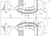
- FIG. 1shows a detailed representation of a dynamoelectric machine 1 with a drive shaft 2 corresponding to the drive shaft according to the invention.
- a rotor section 3is fixed non-rotatably on the drive shaft 2 .
- FIG. 1shows a bearing 4 of the drive shaft 2 .
- the drive shaft 2can be mounted in the bearing 4 and be mechanically connected thereto.
- the rotor and the bearingare examples of heat sources whose heat is coupled to the drive shaft 2 .
- the drive shaft 2has two different heat conduction paths 20 , 21 that are thermally separate from one another, which, for example, extend along an axial direction X of the drive shaft 2 .
- a direction in which heat is dissipated in the example shown,is illustrated with arrows (heat flow direction). This direction can be parallel to the axial direction X of the drive shaft 2 .
- the heat conduction paths 20 , 21can be made of the same materials or different materials.
- the heat conduction paths 20 , 21can, for example, be thermally separated by a layer 22 of a material with thermal conductivity that is worse than the thermal conductivity of the two heat conduction paths 20 , 21 .
- each heat conduction path 20 , 21is monolithic.
- Each path 20 or 21has two ends 200 , 210 or 201 , 211 . It is expedient for the ends of the respective heat conduction path to be physically separate from one another (see FIG. 1 ). Heat can be coupled into one end 200 , 201 of the corresponding heat conduction paths 20 , 21 and out of the other end 210 , 211 . It may be identified from the figure that the rotor section 3 is thermally coupled to a first end 200 of a first heat conduction path 20 and the bearing 4 to be thermally coupled to a first end 201 of a second heat conduction path 21 .
- heat from different heat sources 3 , 4flows (see arrow directions) along the different paths 20 , 21 and in each case is coupled out of the drive shaft 2 from a second end 210 , 211 of the corresponding heat conduction path 20 , 21 .
- the second ends of the different heat conduction pathsare thermally coupled to a heat sink.
- the heat sinkcan, for example, be a fan 5 in thermal contact with the drive shaft 2 or a heat exchanger (not shown) or a cooling medium, for example air.
- An exemplary direction of flow 6 of cooling aircan also be seen in FIG. 1 .
- the fan 5draws heat from the drive shaft 2 and dissipates it to the cooling medium.
- the machine 1can also be provided with a heat-separating apparatus 7 .
- This separating apparatusis embodied such and in contact with the drive shaft 2 such that heat from the second end of one heat conduction path (for example the heat conduction path 21 ) cannot couple back into the second end of the other heat conduction path (for example the heat conduction path 20 ).
- Thiscan enable thermal separation outside the drive shaft 2 in order to keep the thermal coupling low there as well, thus reducing heat flow “back” to the respective heat source (for example rotor section 3 or bearing 4 ).
- the heat-separating apparatus 6can, for example, be a partition wall made of a non-thermally conductive material or at least of a material with thermal conductivity that is worse than the thermal conductivity of air. For example, it is possible to use the same material as that used for the layer 22 .
- the aforementioned fan 5for example an integral fan, can be fixed to the shaft end 23 of the drive shaft 2 arranged downstream of the heat-emitting heat sources—here the rotor section 3 and the bearing 4 —in the axial direction X.
- the shaft end 23is preferably in thermal contact with a heat sink, such as, for example, cooling medium 6 , fan 5 or heat exchanger (not shown).
- a heat sinksuch as, for example, cooling medium 6 , fan 5 or heat exchanger (not shown).
- the fan 7can be thermally coupled to or in thermally conductive contact with the second ends 210 , 211 of both heat conduction paths 20 , 21 .
- the aforementioned heat-separating apparatus 7can be part of the fan 5 . It is quite conceivable for different fans to be in thermally conductive contact with the second ends of different heat conduction paths—this enables different heat conduction paths to have different heat sinks.
- auxiliary thermal element 8is provided within the dynamoelectric machine 1 (for example a further fan) which either dissipates heat to the interior of the dynamoelectric machine 1 or absorbs heat from there and supplies it to the fan 5 via one of the heat paths—here via the first heat conduction path 20 . It is emphasized at this point that it is also possible for a plurality of different heat sources with similar temperature levels to be coupled to each heat conduction path. In the above-described exemplary embodiment, these heat sources are: the rotor section 3 and the auxiliary thermal element 8 .
- FIG. 2shows a sectional view of FIG. 1 .
- the drive shaft 2can, for example, be provided as a solid shaft. It may be identified from a joint examination of FIG. 1 and FIG. 2 that the heat conduction paths 20 , 21 can be arranged coaxially.
- the second heat conduction path 21can be circular in the radial direction and U-shaped in the axial direction. With the exception of its two ends 201 , 211 , the second heat conduction path 21 can be thermally separated from an outer peripheral surface 24 of the drive shaft 2 by a further layer 25 made of a material with thermal conductivity that is at least worse than the thermal conductivity of air. This can further improve heat transfer through the second path 21 .
- the first heat conduction path 20can remain partially non-thermally insulated: FIG. 1 shows that no thermally insulating layer is provided between the greater part of the first heat conduction path 20 and the outer peripheral surface 24 of the drive shaft 2 .
- a layeris of course conceivable and can be used to improve convection properties of the first heat conduction path 20 .
- thermally insulating layer 22 and the further thermally insulating layer 25define an intermediate space in the drive shaft 2 that forms the heat conduction path 21 .
- the other heat conduction path 20is formed by a space defined between the thermally insulating layer 22 and the outer peripheral surface 24 of the drive shaft 2 .
- the heat conduction paths 20 , 21can be (intrinsically) closed in the circumferential direction of the drive shaft 2 . This makes it possible to dissipate heat from a heat source, for example from a bearing 4 , at any angle of rotation of the drive shaft 2 . In other words, while the drive shaft 2 rotates, the heat conduction paths 20 , 21 can continuously dissipate heat from the heat sources due to their closed shape. This can increase the efficiency of heat dissipation.
- FIG. 3shows a section of a drive shaft 2000 transverse to its axial direction X according to a further preferred embodiment.
- FIG. 3shows that the aforementioned heat conduction paths 20 , 21 can have a different geometric shape.
- the thermally conductive paths 2001 , 2002 , 2003 , 2004 , 2005 of the shaft 2000can also have a segment-like structure when viewed in the circumferential direction. This depends on the respective thermal coupling of the respective heat source to the drive shaft 2000 .
- the heat conduction paths 2001 to 2005can be embodied as segments of a ring, in particular segments of an annulus of the hollow shaft with a ring-shaped, in particular annulus-shaped hollow shaft 2000 .
- heat and heat sources which can rotate with the drive shaft 2000for example are firmly connectable to the drive shaft 2000 , can be dissipated more efficiently.
- the heat conduction paths 2001 to 2005can be formed by intermediate spaces defined between the thermally insulating layers 22 .
- Each Insulating layer 22can extend from an outer peripheral surface 24 of the drive shaft 2000 to an inner peripheral surface 27 of the drive shaft 2000 .
- the drive shaft 2000can have a receptacle 26 or a cavity in its interior.
- This receptacle 26which is, for example, arranged coaxially with the drive shaft 2000 , preferably serves as a heat sink or as heat sinks.
- a coolant 6for example air, can flow through the receptacle and enable heat to be transferred along the respective heat conduction paths 2001 to 2005 from the outer peripheral surface 24 to the inner peripheral surface 27 of the hollow shaft 2000 .
- this embodimentcan also be provided with technical features that have already been described, for example to avoid “thermal short circuits” or to improve the convection properties without the need for separate adaptation of other features.
- the shaft 2 , 2000can be additionally equipped with a thermal and/or electric block 28 ( FIG. 4 ).
- This block 28can, for example, take the form of a mechanical coupling and be configured to connect a first part 29 with a second part 30 of the drive shaft 2 , 2000 .
- the block 28can be labyrinth-like.
- the above-described drive shaft 2 , 2000can be manufactured with the aid of an additive manufacturing method or a 3D printing method.
- the manufacture of a shaft of this kind 2 , 2000is based on knowledge of the distribution of the heat sources 3 , 4 and preferably the heat sink(s) 5 , 6 along the drive shaft 2 , 2000 .
- Each heat source 3 , 4has its docking points or stations on the drive shaft 2 , 2000 , which are distributed axially and/or radially and/or in the circumferential direction. These docking stations can, for example, define or specify the positions of the (first) ends 200 , 201 of the heat conduction paths 20 , 21 .
- This knowledgecan be used as the basis for designing a 3D model on a computer of the drive shaft 2 , 2000 to be manufactured.
- This modelis used as input for an additive manufacturing method or a 3D printing method, with which the drive shaft 2 , 2000 with the at least two different heat conduction paths 20 , 21 , 2001 , 2002 , 2003 , 2004 , 2005 that are thermally separate from one another is manufactured from different layers/materials.
- the aforementioned block 28can, for example, also be formed by means of the additive manufacturing method.
- FIG. 5shows by way of example a driving machine or system 100 with the aforementioned dynamoelectric machine 1 .
- FIG. 6shows by way of example a driving machine or system 100 with one of the aforementioned drive shafts 2 , 2000 .
- FIGS. 1 to 4can be screenshots from a computer program according to the invention or from digital twins according to the invention. Hence, FIGS. 1 to 4 also show a digitized image of the drive shaft 2 , 2000 and all other features of the drive shaft 2 , 2000 as described above.
- Said computer program and/or the corresponding digital twincan, for example, be used to simulate the heat flow within the drive shaft 2 , 2000 and/or within the dynamoelectric machine 1 or the driving machine comprising this dynamoelectric machine 1 without having to carry out actual tests.
Landscapes
- Engineering & Computer Science (AREA)
- Power Engineering (AREA)
- Chemical & Material Sciences (AREA)
- Materials Engineering (AREA)
- Manufacturing & Machinery (AREA)
- Mechanical Engineering (AREA)
- General Engineering & Computer Science (AREA)
- Physics & Mathematics (AREA)
- Optics & Photonics (AREA)
- Ocean & Marine Engineering (AREA)
- Motor Or Generator Cooling System (AREA)
Abstract
Description
- computer-aided design of a three-dimensional model of the aforementioned drive shaft based on a distribution of heat sources and preferably sink(s) in the dynamoelectric machine along the drive shaft;
- manufacturing the drive shaft according to the three-dimensional model design by means of an additive manufacturing method or a 3D printing method.
Claims (21)
Applications Claiming Priority (4)
| Application Number | Priority Date | Filing Date | Title |
|---|---|---|---|
| EP19200500.7AEP3799264B1 (en) | 2019-09-30 | 2019-09-30 | Drive shaft of dynamo-electric machine |
| DE19200500.7 | 2019-09-30 | ||
| EP19200500 | 2019-09-30 | ||
| PCT/EP2020/076397WO2021063745A1 (en) | 2019-09-30 | 2020-09-22 | Drive shaft of a dynamoelectrical machine and corresponding manufacturing method |
Publications (2)
| Publication Number | Publication Date |
|---|---|
| US20220344990A1 US20220344990A1 (en) | 2022-10-27 |
| US12323009B2true US12323009B2 (en) | 2025-06-03 |
Family
ID=68104478
Family Applications (1)
| Application Number | Title | Priority Date | Filing Date |
|---|---|---|---|
| US17/764,875Active2041-07-03US12323009B2 (en) | 2019-09-30 | 2020-09-22 | Drive shaft of a dynamoelectrical machine and corresponding manufacturing method |
Country Status (4)
| Country | Link |
|---|---|
| US (1) | US12323009B2 (en) |
| EP (2) | EP3799264B1 (en) |
| CN (1) | CN114502848B (en) |
| WO (1) | WO2021063745A1 (en) |
Citations (39)
| Publication number | Priority date | Publication date | Assignee | Title |
|---|---|---|---|---|
| JPS5577350A (en) | 1978-12-04 | 1980-06-11 | Hitachi Ltd | Cooling device for rotary machine |
| DE4230379A1 (en) | 1992-09-11 | 1994-03-17 | Bosch Gmbh Robert | Electric drive motor for power tool or domestic appliance - with rotor shaft acting as heat pipe having hollow space partially filled with liquid |
| JPH06141509A (en) | 1992-10-27 | 1994-05-20 | Mitsubishi Electric Corp | Rotating machine |
| JPH06178501A (en) | 1992-12-04 | 1994-06-24 | Fuji Electric Co Ltd | Totally closed fan-shaped rotating electric machine |
| DE19900559C1 (en) | 1999-01-09 | 2000-09-21 | Mannesmann Vdo Ag | Compact electric motor e.g. for vehicle power steering or engine valve adjustment, has rotor shaft provided with section having high heat conduction coefficient for dissipating heat generated by motor |
| JP2002017066A (en) | 2000-06-29 | 2002-01-18 | Namiki Precision Jewel Co Ltd | Heat dissipation structure of small cylindrical coreless motor |
| DE102004053424B4 (en) | 2004-11-05 | 2006-09-28 | Borgwarner Inc., Auburn Hills | turbine shaft |
| JP2007010018A (en) | 2005-06-30 | 2007-01-18 | Nissan Motor Co Ltd | Rotating shaft structure of high temperature fluid fan |
| DE102006045178A1 (en) | 2006-09-25 | 2008-04-03 | Siemens Ag | Electric machine, has winding system arranged in grooves of laminated core of stator, and laminated core of rotor arranged at shaft in torque-proof manner, where shaft is supported in two bearings in bearing flanges at housing |
| CN101325352A (en) | 2007-06-13 | 2008-12-17 | 上海熊猫机械(集团)有限公司 | Air-cooled motor |
| US20080309174A1 (en) | 2005-06-16 | 2008-12-18 | Siemens Aktiengesellschaft | Electric Motor with Permanent Magnet Excitation and Rotor Cooling |
| DE102009019154A1 (en) | 2009-04-28 | 2011-02-17 | Continental Automotive Gmbh | Turbocharger rotor shaft for use in turbocharger, has one or multiple cores which consist of one, two or multiple bearings and coatings for casing |
| US20110241040A1 (en) | 2010-04-05 | 2011-10-06 | Taiwan Semiconductor Manufacturing Company, Ltd. | Novel semiconductor package with through silicon vias |
| CN102905590A (en) | 2010-05-21 | 2013-01-30 | 皇家飞利浦电子股份有限公司 | Device for heating water and producing steam |
| JP2014135859A (en) | 2013-01-11 | 2014-07-24 | Kobe Steel Ltd | Electric motor |
| US20140333161A1 (en) | 2013-05-07 | 2014-11-13 | Dr. Ing. H.C. F. Porsche Aktiengesellschaft | Electric machine having a cooled rotor shaft |
| US20150022041A1 (en) | 2013-07-18 | 2015-01-22 | Honeywell International Inc. | Method of cooling a generator or motor rotor with end disks and a hybrid shaft assembly |
| CN104776110A (en)* | 2015-04-13 | 2015-07-15 | 宋天顺 | Hollow shaft and rotating shaft |
| DE102014202055A1 (en) | 2014-02-05 | 2015-08-06 | Magna Powertrain Ag & Co. Kg | Electric machine |
| US20150335070A1 (en) | 2014-05-20 | 2015-11-26 | R.J. Reynolds Tobacco Company | Electrically-powered aerosol delivery system |
| US20160028283A1 (en) | 2014-07-23 | 2016-01-28 | Kurt M. Chankaya | Vacuum Gap Generators and Motors |
| JP2016149898A (en) | 2015-02-13 | 2016-08-18 | ファナック株式会社 | Rotor having flow path for cooling fluid and electric motor including the rotor |
| US20160352201A1 (en) | 2015-05-27 | 2016-12-01 | Hamilton Sundstrand Corporation | Integrated heat dissipative structure for electric machine |
| WO2017013144A1 (en) | 2015-07-20 | 2017-01-26 | Avl List Gmbh | Electrical machine |
| EP3131189A1 (en) | 2015-08-12 | 2017-02-15 | Siemens Aktiengesellschaft | Rotor of an electric machine |
| WO2017050447A1 (en) | 2015-09-22 | 2017-03-30 | Siemens Aktiengesellschaft | Cooling an electric rotating machine |
| WO2017104560A1 (en) | 2015-12-17 | 2017-06-22 | 株式会社デンソー | Motor shaft |
| DE102016202416A1 (en) | 2016-02-17 | 2017-08-17 | Hirschvogel Umformtechnik Gmbh | Rotor shaft arrangement and method for its production |
| WO2017207212A1 (en) | 2016-06-03 | 2017-12-07 | Siemens Aktiengesellschaft | Dynamoelectric machine having a thermosiphon |
| WO2017211477A1 (en) | 2016-06-07 | 2017-12-14 | Siemens Aktiengesellschaft | Rotor for a reluctance machine |
| CN206992887U (en) | 2017-06-26 | 2018-02-09 | 上海嘉熙科技有限公司 | Motor shaft assembly and the motor with motor shaft assembly |
| WO2018059844A1 (en)* | 2016-09-29 | 2018-04-05 | Siemens Aktiengesellschaft | Cooling of a pod drive |
| DE102016124632A1 (en) | 2016-12-16 | 2018-06-21 | Dr. Ing. H.C. F. Porsche Aktiengesellschaft | electric motor |
| WO2018153637A1 (en) | 2017-02-21 | 2018-08-30 | Siemens Aktiengesellschaft | Production of functional units of dynamoelectric machines by additive manufacturing methods |
| FR3065124A1 (en) | 2017-04-10 | 2018-10-12 | Liebherr-Aerospace Toulouse Sas | ROTATING MACHINE COMPRISING A ROTARY SHAFT INCLUDING A HEAT PUMP |
| DE102017112835A1 (en) | 2017-06-12 | 2018-12-13 | Dr. Ing. H.C. F. Porsche Aktiengesellschaft | Electric machine, motor vehicle and method for producing an electrical machine |
| GB2568368A (en) | 2017-09-13 | 2019-05-15 | Fisher Rosemount Systems Inc | Assistant application for a modular control system |
| US20190234313A1 (en) | 2018-01-30 | 2019-08-01 | General Electric Company | Additively Manufactured Rotating Shaft |
| CN110098691A (en) | 2019-06-13 | 2019-08-06 | 北斗航天汽车(北京)有限公司 | A kind of motor of stator rotor synchronous cooling |
Family Cites Families (1)
| Publication number | Priority date | Publication date | Assignee | Title |
|---|---|---|---|---|
| GB201618464D0 (en)* | 2016-11-02 | 2016-12-14 | Jaguar Land Rover Ltd | Cooling of an electrical machine |
- 2019
- 2019-09-30EPEP19200500.7Apatent/EP3799264B1/enactiveActive
- 2020
- 2020-09-22EPEP20789455.1Apatent/EP4008048B1/enactiveActive
- 2020-09-22CNCN202080068426.4Apatent/CN114502848B/enactiveActive
- 2020-09-22USUS17/764,875patent/US12323009B2/enactiveActive
- 2020-09-22WOPCT/EP2020/076397patent/WO2021063745A1/ennot_activeCeased
Patent Citations (46)
| Publication number | Priority date | Publication date | Assignee | Title |
|---|---|---|---|---|
| JPS5577350A (en) | 1978-12-04 | 1980-06-11 | Hitachi Ltd | Cooling device for rotary machine |
| DE4230379A1 (en) | 1992-09-11 | 1994-03-17 | Bosch Gmbh Robert | Electric drive motor for power tool or domestic appliance - with rotor shaft acting as heat pipe having hollow space partially filled with liquid |
| JPH06141509A (en) | 1992-10-27 | 1994-05-20 | Mitsubishi Electric Corp | Rotating machine |
| JPH06178501A (en) | 1992-12-04 | 1994-06-24 | Fuji Electric Co Ltd | Totally closed fan-shaped rotating electric machine |
| DE19900559C1 (en) | 1999-01-09 | 2000-09-21 | Mannesmann Vdo Ag | Compact electric motor e.g. for vehicle power steering or engine valve adjustment, has rotor shaft provided with section having high heat conduction coefficient for dissipating heat generated by motor |
| JP2002017066A (en) | 2000-06-29 | 2002-01-18 | Namiki Precision Jewel Co Ltd | Heat dissipation structure of small cylindrical coreless motor |
| DE102004053424B4 (en) | 2004-11-05 | 2006-09-28 | Borgwarner Inc., Auburn Hills | turbine shaft |
| US20080309174A1 (en) | 2005-06-16 | 2008-12-18 | Siemens Aktiengesellschaft | Electric Motor with Permanent Magnet Excitation and Rotor Cooling |
| JP2007010018A (en) | 2005-06-30 | 2007-01-18 | Nissan Motor Co Ltd | Rotating shaft structure of high temperature fluid fan |
| DE102006045178A1 (en) | 2006-09-25 | 2008-04-03 | Siemens Ag | Electric machine, has winding system arranged in grooves of laminated core of stator, and laminated core of rotor arranged at shaft in torque-proof manner, where shaft is supported in two bearings in bearing flanges at housing |
| CN101325352A (en) | 2007-06-13 | 2008-12-17 | 上海熊猫机械(集团)有限公司 | Air-cooled motor |
| DE102009019154A1 (en) | 2009-04-28 | 2011-02-17 | Continental Automotive Gmbh | Turbocharger rotor shaft for use in turbocharger, has one or multiple cores which consist of one, two or multiple bearings and coatings for casing |
| US20110241040A1 (en) | 2010-04-05 | 2011-10-06 | Taiwan Semiconductor Manufacturing Company, Ltd. | Novel semiconductor package with through silicon vias |
| TW201135884A (en) | 2010-04-05 | 2011-10-16 | Taiwan Semiconductor Mfg | Semiconductor package substrate |
| CN102905590A (en) | 2010-05-21 | 2013-01-30 | 皇家飞利浦电子股份有限公司 | Device for heating water and producing steam |
| US20130055902A1 (en) | 2010-05-21 | 2013-03-07 | Koninklijke Philips Electronics N.V. | Device for heating water and producing steam |
| JP2014135859A (en) | 2013-01-11 | 2014-07-24 | Kobe Steel Ltd | Electric motor |
| US20140333161A1 (en) | 2013-05-07 | 2014-11-13 | Dr. Ing. H.C. F. Porsche Aktiengesellschaft | Electric machine having a cooled rotor shaft |
| JP2014220996A (en) | 2013-05-07 | 2014-11-20 | ドクター エンジニール ハー ツェー エフ ポルシェ アクチエンゲゼルシャフトDr. Ing. h.c.F. Porsche Aktiengesellschaft | Electric machine having cooling rotor shaft |
| US20150022041A1 (en) | 2013-07-18 | 2015-01-22 | Honeywell International Inc. | Method of cooling a generator or motor rotor with end disks and a hybrid shaft assembly |
| DE102014202055A1 (en) | 2014-02-05 | 2015-08-06 | Magna Powertrain Ag & Co. Kg | Electric machine |
| US20150335070A1 (en) | 2014-05-20 | 2015-11-26 | R.J. Reynolds Tobacco Company | Electrically-powered aerosol delivery system |
| KR101957819B1 (en) | 2014-05-20 | 2019-03-13 | 레이 스트라티직 홀딩스, 인크. | Electrically-powered aerosol delivery system |
| US20160028283A1 (en) | 2014-07-23 | 2016-01-28 | Kurt M. Chankaya | Vacuum Gap Generators and Motors |
| JP2016149898A (en) | 2015-02-13 | 2016-08-18 | ファナック株式会社 | Rotor having flow path for cooling fluid and electric motor including the rotor |
| US20160241113A1 (en)* | 2015-02-13 | 2016-08-18 | Fanuc Corporation | Rotor having flow path of cooling fluid and electric motor including the rotor |
| CN104776110A (en)* | 2015-04-13 | 2015-07-15 | 宋天顺 | Hollow shaft and rotating shaft |
| US20160352201A1 (en) | 2015-05-27 | 2016-12-01 | Hamilton Sundstrand Corporation | Integrated heat dissipative structure for electric machine |
| WO2017013144A1 (en) | 2015-07-20 | 2017-01-26 | Avl List Gmbh | Electrical machine |
| EP3131189A1 (en) | 2015-08-12 | 2017-02-15 | Siemens Aktiengesellschaft | Rotor of an electric machine |
| US20180233977A1 (en) | 2015-08-12 | 2018-08-16 | Siemens Aktiengesellschaft | Rotor Of An Electric Machine |
| WO2017050447A1 (en) | 2015-09-22 | 2017-03-30 | Siemens Aktiengesellschaft | Cooling an electric rotating machine |
| WO2017104560A1 (en) | 2015-12-17 | 2017-06-22 | 株式会社デンソー | Motor shaft |
| DE102016202416A1 (en) | 2016-02-17 | 2017-08-17 | Hirschvogel Umformtechnik Gmbh | Rotor shaft arrangement and method for its production |
| US20170237316A1 (en)* | 2016-02-17 | 2017-08-17 | Hirschvogel Umformtechnik Gmbh | Rotor Shaft Arrangement and Method for Manufacturing the Same |
| WO2017207212A1 (en) | 2016-06-03 | 2017-12-07 | Siemens Aktiengesellschaft | Dynamoelectric machine having a thermosiphon |
| WO2017211477A1 (en) | 2016-06-07 | 2017-12-14 | Siemens Aktiengesellschaft | Rotor for a reluctance machine |
| WO2018059844A1 (en)* | 2016-09-29 | 2018-04-05 | Siemens Aktiengesellschaft | Cooling of a pod drive |
| DE102016124632A1 (en) | 2016-12-16 | 2018-06-21 | Dr. Ing. H.C. F. Porsche Aktiengesellschaft | electric motor |
| WO2018153637A1 (en) | 2017-02-21 | 2018-08-30 | Siemens Aktiengesellschaft | Production of functional units of dynamoelectric machines by additive manufacturing methods |
| FR3065124A1 (en) | 2017-04-10 | 2018-10-12 | Liebherr-Aerospace Toulouse Sas | ROTATING MACHINE COMPRISING A ROTARY SHAFT INCLUDING A HEAT PUMP |
| DE102017112835A1 (en) | 2017-06-12 | 2018-12-13 | Dr. Ing. H.C. F. Porsche Aktiengesellschaft | Electric machine, motor vehicle and method for producing an electrical machine |
| CN206992887U (en) | 2017-06-26 | 2018-02-09 | 上海嘉熙科技有限公司 | Motor shaft assembly and the motor with motor shaft assembly |
| GB2568368A (en) | 2017-09-13 | 2019-05-15 | Fisher Rosemount Systems Inc | Assistant application for a modular control system |
| US20190234313A1 (en) | 2018-01-30 | 2019-08-01 | General Electric Company | Additively Manufactured Rotating Shaft |
| CN110098691A (en) | 2019-06-13 | 2019-08-06 | 北斗航天汽车(北京)有限公司 | A kind of motor of stator rotor synchronous cooling |
Non-Patent Citations (3)
| Title |
|---|
| Machine translation of CN-104776110-A. (Year: 2015).* |
| Machine translation of WO-2018059844-A1. (Year: 2018).* |
| PCT International Search Report and Written Opinion of International Searching Authority mailed Nov. 2, 2020 corresponding to PCT International Application No. PCT/EP2020/076397 filed Sep. 22, 2020. |
Also Published As
| Publication number | Publication date |
|---|---|
| EP4008048B1 (en) | 2024-05-22 |
| EP3799264A1 (en) | 2021-03-31 |
| US20220344990A1 (en) | 2022-10-27 |
| CN114502848A (en) | 2022-05-13 |
| EP4008048A1 (en) | 2022-06-08 |
| EP4008048C0 (en) | 2024-05-22 |
| CN114502848B (en) | 2024-07-05 |
| EP3799264B1 (en) | 2023-04-19 |
| WO2021063745A1 (en) | 2021-04-08 |
Similar Documents
| Publication | Publication Date | Title |
|---|---|---|
| US20170237316A1 (en) | Rotor Shaft Arrangement and Method for Manufacturing the Same | |
| US11303174B2 (en) | Rotor for an electric machine | |
| US11205931B2 (en) | Electric machine and rotor with cooling channel | |
| US9413208B2 (en) | Enhanced cooling of enclosed air cooled high power motors | |
| US7629717B2 (en) | Totally-enclosed fan-cooled motor | |
| US10784745B2 (en) | Stators for electrical machines | |
| CN1278475C (en) | Ventilation fan cooled motor | |
| CN107925305B (en) | Cooling system for an electric machine | |
| US11114924B2 (en) | Squirrel-cage rotor for an asynchronous machine | |
| US9525324B2 (en) | Axial flux electrical machines | |
| MX2008003585A (en) | Motor cooling arrangement. | |
| WO2015008390A1 (en) | Liquid-cooled electric motor | |
| CN105531911A (en) | Motors with heat conduction | |
| CN106257803A (en) | Motor | |
| JP2017085765A (en) | Rotary electric machine | |
| US20180212494A1 (en) | Electrical machine | |
| US10720814B2 (en) | Electrical machine and method for cooling the electrical machine | |
| US12323009B2 (en) | Drive shaft of a dynamoelectrical machine and corresponding manufacturing method | |
| US9793784B2 (en) | Cooling structure for slip ring device | |
| WO2005124971A1 (en) | Totally-enclosed fancooled type motor | |
| US8772990B2 (en) | Stator system with a cooling arrangement | |
| CN119546521A (en) | Propulsion device for aircraft | |
| CN214314874U (en) | Liquid cooling motor | |
| JP2019213397A (en) | Fully enclosed rotating electrical machine, frame structure, and frame structure design method | |
| WO2024185149A1 (en) | Rotating electrical machine |
Legal Events
| Date | Code | Title | Description |
|---|---|---|---|
| AS | Assignment | Owner name:SIEMENS AKTIENGESELLSCHAFT, GERMANY Free format text:ASSIGNMENT OF ASSIGNORS INTEREST;ASSIGNOR:HOESLE, MARKUS;REEL/FRAME:059429/0563 Effective date:20220316 | |
| FEPP | Fee payment procedure | Free format text:ENTITY STATUS SET TO UNDISCOUNTED (ORIGINAL EVENT CODE: BIG.); ENTITY STATUS OF PATENT OWNER: LARGE ENTITY | |
| STPP | Information on status: patent application and granting procedure in general | Free format text:DOCKETED NEW CASE - READY FOR EXAMINATION | |
| AS | Assignment | Owner name:INNOMOTICS GMBH, GERMANY Free format text:ASSIGNMENT OF ASSIGNORS INTEREST;ASSIGNOR:SIEMENS AKTIENGESELLSCHAFT;REEL/FRAME:065612/0733 Effective date:20231107 | |
| STPP | Information on status: patent application and granting procedure in general | Free format text:NON FINAL ACTION MAILED | |
| STPP | Information on status: patent application and granting procedure in general | Free format text:RESPONSE TO NON-FINAL OFFICE ACTION ENTERED AND FORWARDED TO EXAMINER | |
| STPP | Information on status: patent application and granting procedure in general | Free format text:FINAL REJECTION MAILED | |
| STPP | Information on status: patent application and granting procedure in general | Free format text:ADVISORY ACTION MAILED | |
| STPP | Information on status: patent application and granting procedure in general | Free format text:DOCKETED NEW CASE - READY FOR EXAMINATION | |
| STPP | Information on status: patent application and granting procedure in general | Free format text:NON FINAL ACTION MAILED | |
| STPP | Information on status: patent application and granting procedure in general | Free format text:RESPONSE TO NON-FINAL OFFICE ACTION ENTERED AND FORWARDED TO EXAMINER | |
| STPP | Information on status: patent application and granting procedure in general | Free format text:NOTICE OF ALLOWANCE MAILED -- APPLICATION RECEIVED IN OFFICE OF PUBLICATIONS | |
| STCF | Information on status: patent grant | Free format text:PATENTED CASE |