US12320584B2 - Portable cooler - Google Patents
Portable coolerDownload PDFInfo
- Publication number
- US12320584B2 US12320584B2US18/328,486US202318328486AUS12320584B2US 12320584 B2US12320584 B2US 12320584B2US 202318328486 AUS202318328486 AUS 202318328486AUS 12320584 B2US12320584 B2US 12320584B2
- Authority
- US
- United States
- Prior art keywords
- container
- cooler
- cooler container
- heat sink
- power
- Prior art date
- Legal status (The legal status is an assumption and is not a legal conclusion. Google has not performed a legal analysis and makes no representation as to the accuracy of the status listed.)
- Active
Links
Images


Classifications
- F—MECHANICAL ENGINEERING; LIGHTING; HEATING; WEAPONS; BLASTING
- F25—REFRIGERATION OR COOLING; COMBINED HEATING AND REFRIGERATION SYSTEMS; HEAT PUMP SYSTEMS; MANUFACTURE OR STORAGE OF ICE; LIQUEFACTION SOLIDIFICATION OF GASES
- F25D—REFRIGERATORS; COLD ROOMS; ICE-BOXES; COOLING OR FREEZING APPARATUS NOT OTHERWISE PROVIDED FOR
- F25D3/00—Devices using other cold materials; Devices using cold-storage bodies
- F25D3/02—Devices using other cold materials; Devices using cold-storage bodies using ice, e.g. ice-boxes
- F25D3/06—Movable containers
- F25D3/08—Movable containers portable, i.e. adapted to be carried personally
- A—HUMAN NECESSITIES
- A01—AGRICULTURE; FORESTRY; ANIMAL HUSBANDRY; HUNTING; TRAPPING; FISHING
- A01N—PRESERVATION OF BODIES OF HUMANS OR ANIMALS OR PLANTS OR PARTS THEREOF; BIOCIDES, e.g. AS DISINFECTANTS, AS PESTICIDES OR AS HERBICIDES; PEST REPELLANTS OR ATTRACTANTS; PLANT GROWTH REGULATORS
- A01N1/00—Preservation of bodies of humans or animals, or parts thereof
- A01N1/10—Preservation of living parts
- A01N1/14—Mechanical aspects of preservation; Apparatus or containers therefor
- A01N1/142—Apparatus
- A01N1/144—Apparatus for temperature control, e.g. refrigerators or freeze-drying apparatus
- A—HUMAN NECESSITIES
- A01—AGRICULTURE; FORESTRY; ANIMAL HUSBANDRY; HUNTING; TRAPPING; FISHING
- A01N—PRESERVATION OF BODIES OF HUMANS OR ANIMALS OR PLANTS OR PARTS THEREOF; BIOCIDES, e.g. AS DISINFECTANTS, AS PESTICIDES OR AS HERBICIDES; PEST REPELLANTS OR ATTRACTANTS; PLANT GROWTH REGULATORS
- A01N1/00—Preservation of bodies of humans or animals, or parts thereof
- A01N1/10—Preservation of living parts
- A01N1/14—Mechanical aspects of preservation; Apparatus or containers therefor
- A01N1/146—Non-refrigerated containers specially adapted for transporting or storing living parts whilst preserving
- A01N1/148—Non-refrigerated containers specially adapted for transporting or storing living parts whilst preserving with provisions specially adapted for transporting
- F—MECHANICAL ENGINEERING; LIGHTING; HEATING; WEAPONS; BLASTING
- F25—REFRIGERATION OR COOLING; COMBINED HEATING AND REFRIGERATION SYSTEMS; HEAT PUMP SYSTEMS; MANUFACTURE OR STORAGE OF ICE; LIQUEFACTION SOLIDIFICATION OF GASES
- F25B—REFRIGERATION MACHINES, PLANTS OR SYSTEMS; COMBINED HEATING AND REFRIGERATION SYSTEMS; HEAT PUMP SYSTEMS
- F25B21/00—Machines, plants or systems, using electric or magnetic effects
- F25B21/02—Machines, plants or systems, using electric or magnetic effects using Peltier effect; using Nernst-Ettinghausen effect
- F—MECHANICAL ENGINEERING; LIGHTING; HEATING; WEAPONS; BLASTING
- F25—REFRIGERATION OR COOLING; COMBINED HEATING AND REFRIGERATION SYSTEMS; HEAT PUMP SYSTEMS; MANUFACTURE OR STORAGE OF ICE; LIQUEFACTION SOLIDIFICATION OF GASES
- F25D—REFRIGERATORS; COLD ROOMS; ICE-BOXES; COOLING OR FREEZING APPARATUS NOT OTHERWISE PROVIDED FOR
- F25D11/00—Self-contained movable devices, e.g. domestic refrigerators
- F25D11/003—Transport containers
- F—MECHANICAL ENGINEERING; LIGHTING; HEATING; WEAPONS; BLASTING
- F25—REFRIGERATION OR COOLING; COMBINED HEATING AND REFRIGERATION SYSTEMS; HEAT PUMP SYSTEMS; MANUFACTURE OR STORAGE OF ICE; LIQUEFACTION SOLIDIFICATION OF GASES
- F25D—REFRIGERATORS; COLD ROOMS; ICE-BOXES; COOLING OR FREEZING APPARATUS NOT OTHERWISE PROVIDED FOR
- F25D29/00—Arrangement or mounting of control or safety devices
- F25D29/003—Arrangement or mounting of control or safety devices for movable devices
- F—MECHANICAL ENGINEERING; LIGHTING; HEATING; WEAPONS; BLASTING
- F25—REFRIGERATION OR COOLING; COMBINED HEATING AND REFRIGERATION SYSTEMS; HEAT PUMP SYSTEMS; MANUFACTURE OR STORAGE OF ICE; LIQUEFACTION SOLIDIFICATION OF GASES
- F25B—REFRIGERATION MACHINES, PLANTS OR SYSTEMS; COMBINED HEATING AND REFRIGERATION SYSTEMS; HEAT PUMP SYSTEMS
- F25B2321/00—Details of machines, plants or systems, using electric or magnetic effects
- F25B2321/02—Details of machines, plants or systems, using electric or magnetic effects using Peltier effects; using Nernst-Ettinghausen effects
- F25B2321/021—Control thereof
- F25B2321/0211—Control thereof of fans
- F—MECHANICAL ENGINEERING; LIGHTING; HEATING; WEAPONS; BLASTING
- F25—REFRIGERATION OR COOLING; COMBINED HEATING AND REFRIGERATION SYSTEMS; HEAT PUMP SYSTEMS; MANUFACTURE OR STORAGE OF ICE; LIQUEFACTION SOLIDIFICATION OF GASES
- F25B—REFRIGERATION MACHINES, PLANTS OR SYSTEMS; COMBINED HEATING AND REFRIGERATION SYSTEMS; HEAT PUMP SYSTEMS
- F25B2321/00—Details of machines, plants or systems, using electric or magnetic effects
- F25B2321/02—Details of machines, plants or systems, using electric or magnetic effects using Peltier effects; using Nernst-Ettinghausen effects
- F25B2321/021—Control thereof
- F25B2321/0212—Control thereof of electric power, current or voltage
- F—MECHANICAL ENGINEERING; LIGHTING; HEATING; WEAPONS; BLASTING
- F25—REFRIGERATION OR COOLING; COMBINED HEATING AND REFRIGERATION SYSTEMS; HEAT PUMP SYSTEMS; MANUFACTURE OR STORAGE OF ICE; LIQUEFACTION SOLIDIFICATION OF GASES
- F25B—REFRIGERATION MACHINES, PLANTS OR SYSTEMS; COMBINED HEATING AND REFRIGERATION SYSTEMS; HEAT PUMP SYSTEMS
- F25B2321/00—Details of machines, plants or systems, using electric or magnetic effects
- F25B2321/02—Details of machines, plants or systems, using electric or magnetic effects using Peltier effects; using Nernst-Ettinghausen effects
- F25B2321/025—Removal of heat
- F25B2321/0251—Removal of heat by a gas
- F—MECHANICAL ENGINEERING; LIGHTING; HEATING; WEAPONS; BLASTING
- F25—REFRIGERATION OR COOLING; COMBINED HEATING AND REFRIGERATION SYSTEMS; HEAT PUMP SYSTEMS; MANUFACTURE OR STORAGE OF ICE; LIQUEFACTION SOLIDIFICATION OF GASES
- F25B—REFRIGERATION MACHINES, PLANTS OR SYSTEMS; COMBINED HEATING AND REFRIGERATION SYSTEMS; HEAT PUMP SYSTEMS
- F25B2400/00—General features or devices for refrigeration machines, plants or systems, combined heating and refrigeration systems or heat-pump systems, i.e. not limited to a particular subgroup of F25B
- F25B2400/24—Storage receiver heat
- F—MECHANICAL ENGINEERING; LIGHTING; HEATING; WEAPONS; BLASTING
- F25—REFRIGERATION OR COOLING; COMBINED HEATING AND REFRIGERATION SYSTEMS; HEAT PUMP SYSTEMS; MANUFACTURE OR STORAGE OF ICE; LIQUEFACTION SOLIDIFICATION OF GASES
- F25D—REFRIGERATORS; COLD ROOMS; ICE-BOXES; COOLING OR FREEZING APPARATUS NOT OTHERWISE PROVIDED FOR
- F25D16/00—Devices using a combination of a cooling mode associated with refrigerating machinery with a cooling mode not associated with refrigerating machinery
- F—MECHANICAL ENGINEERING; LIGHTING; HEATING; WEAPONS; BLASTING
- F25—REFRIGERATION OR COOLING; COMBINED HEATING AND REFRIGERATION SYSTEMS; HEAT PUMP SYSTEMS; MANUFACTURE OR STORAGE OF ICE; LIQUEFACTION SOLIDIFICATION OF GASES
- F25D—REFRIGERATORS; COLD ROOMS; ICE-BOXES; COOLING OR FREEZING APPARATUS NOT OTHERWISE PROVIDED FOR
- F25D2400/00—General features of, or devices for refrigerators, cold rooms, ice-boxes, or for cooling or freezing apparatus not covered by any other subclass
- F25D2400/12—Portable refrigerators
- F—MECHANICAL ENGINEERING; LIGHTING; HEATING; WEAPONS; BLASTING
- F25—REFRIGERATION OR COOLING; COMBINED HEATING AND REFRIGERATION SYSTEMS; HEAT PUMP SYSTEMS; MANUFACTURE OR STORAGE OF ICE; LIQUEFACTION SOLIDIFICATION OF GASES
- F25D—REFRIGERATORS; COLD ROOMS; ICE-BOXES; COOLING OR FREEZING APPARATUS NOT OTHERWISE PROVIDED FOR
- F25D2400/00—General features of, or devices for refrigerators, cold rooms, ice-boxes, or for cooling or freezing apparatus not covered by any other subclass
- F25D2400/36—Visual displays
- F—MECHANICAL ENGINEERING; LIGHTING; HEATING; WEAPONS; BLASTING
- F25—REFRIGERATION OR COOLING; COMBINED HEATING AND REFRIGERATION SYSTEMS; HEAT PUMP SYSTEMS; MANUFACTURE OR STORAGE OF ICE; LIQUEFACTION SOLIDIFICATION OF GASES
- F25D—REFRIGERATORS; COLD ROOMS; ICE-BOXES; COOLING OR FREEZING APPARATUS NOT OTHERWISE PROVIDED FOR
- F25D2700/00—Means for sensing or measuring; Sensors therefor
- F25D2700/12—Sensors measuring the inside temperature
- F—MECHANICAL ENGINEERING; LIGHTING; HEATING; WEAPONS; BLASTING
- F25—REFRIGERATION OR COOLING; COMBINED HEATING AND REFRIGERATION SYSTEMS; HEAT PUMP SYSTEMS; MANUFACTURE OR STORAGE OF ICE; LIQUEFACTION SOLIDIFICATION OF GASES
- F25D—REFRIGERATORS; COLD ROOMS; ICE-BOXES; COOLING OR FREEZING APPARATUS NOT OTHERWISE PROVIDED FOR
- F25D31/00—Other cooling or freezing apparatus
- F25D31/006—Other cooling or freezing apparatus specially adapted for cooling receptacles, e.g. tanks
- F25D31/007—Bottles or cans
Definitions
- the inventionis directed to a portable cooler, and more particularly to a stackable portable cooler.
- Portable coolersare used to store products (e.g., liquids, beverages, medicine, organs, food, etc.) in a cooled state.
- productse.g., liquids, beverages, medicine, organs, food, etc.
- Someare Styrofoam containers that are often filled with ice to keep the product in a cooled state.
- the iceeventually melts, soaking the products and requiring the emptying of the liquid.
- Such coolerscan also leak during transport, which is undesirable.
- such coolersare undesirable for transporting goods across long distances due to their inability to maintain the product in a cooled state, the melting of ice and/or possible leaking of liquid from the cooler. Therefore, such coolers are undesirable for use with temperature sensitive products (e.g., food, medicine, organ transplants, perishable material, etc.).
- an improved portable coolercan optionally have a vacuum-insulated double wall chamber that can be sealed with a lid (e.g., with a vacuum-insulated lid). This allows the temperature in the chamber to be maintained (e.g., be maintained substantially constant) for a prolonged period of time (e.g., 2 days, 1 day, 12 hours, 8 hours, 6 hours, etc.).
- the chambercan hold perishable contents (e.g., medicine, food, other perishables, etc.) therein and a phase change material (e.g., one or more ice packs, a phase change material sleeve) in thermal communication (e.g., thermal contact) with the perishable contents.
- the coolerhas an insulated outer housing (e.g., made of foam, such as lightweight foam).
- the containercan have a cooling fan and one or more air intake openings.
- the cooling fanis operable to cool the chamber and/or the phase change material in the chamber.
- the containerhas one or more sensors that sense a temperature of the chamber and/or contents in the chamber and communicate the information with circuitry.
- the sensed temperature informationis communicated (e.g., wirelessly, via a port on the container, such as a USB port) with an electronic device (e.g., a smartphone, a cloud server, a remote laptop or desktop computer, a USB drive).
- an electronic devicee.g., a smartphone, a cloud server, a remote laptop or desktop computer, a USB drive.
- the containerhas an electronic screen (e.g., digital screen) that can illustrate one or more of a) the temperature sensed by the temperature sensors in the chamber, b) the name of the addressee and/or shipping/delivery address of the container and/or c) the name of the sender and/or shipper/sender address.
- an electronic screene.g., digital screen
- the containerhas a user interface (e.g., a button) that can actuated by a user to one or more of: a) change the name of the addressee and/or shipping/delivery address of the container and/or b) automatically contact a package delivery service (e.g., FedEx, DHL) to request a pick-up of the container.
- a user interfacee.g., a button
- a package delivery servicee.g., FedEx, DHL
- a portable cooler container with active temperature control systemis provided.
- the active temperature control systemis operated to heat or cool a chamber of a vessel to approach a temperature set point suitable for the contents in the cooler container.
- a stackable portable coolerthat allows power transfer between the stacked coolers to charge and/or power the cooling system in the stacked coolers.
- a stackable portable coolerthat allows for removal of heat from each of the stacked coolers without having an upper cooler impede the cooling function of a lower cooler in the stack.
- a stackable portable cooler container with active temperature controlcomprises a container body having a chamber defined by a base and an inner peripheral wall of the container body.
- the containeralso comprises a temperature control system comprising one or more thermoelectric elements configured to actively heat or cool at least a portion of the chamber, and circuitry configured to control an operation of the one or more thermoelectric elements to heat or cool at least a portion of the chamber to a predetermined temperature or temperature range.
- the containercan include one or more batteries configured to provide power to one or both of the circuitry and the one or more thermoelectric elements.
- the circuitryis further configured to wirelessly communicate with a cloud-based data storage system and/or a remote electronic device.
- a portable cooler container with active temperature controlis provided.
- a display screenis disposed on a surface of the container body, the display screen configured to selectively display shipping information for the portable cooler container using electronic ink.
- the display screenis operable to automatically change a shipping address displayed to a different address (e.g., a sender's address for return of the portable cooler to the sender).
- actuation of the display screen to display a shipping addresse.g., a delivery address, a sender's address when the portable cooler is to be returned to the sender
- electronics in the coolerwirelessly communicate a signal to a shipping carrier informing the shipping carrier that a shipping label has been assigned to the portable cooler and that the cooler is ready for pick-up and shipping.
- a portable cooler container systemcomprising a container body having a chamber configured to receive one or more perishable goods.
- a sleeveis disposed about the chamber and housing a phase change material or thermal mass.
- a conduitextends through the sleeve, an outer surface of the conduit in thermal communication with the phase change material or thermal mass.
- a lidis hingedly coupleable or removably coupleable to the container body to access the chamber.
- the cooler container systemalso comprises a temperature control system.
- the temperature control systemcomprises a cold side heat sink in thermal communication with at least a portion of the conduit, a hot side heat sink, and a thermoelectric module interposed between and in thermal communication with the cold side heat sink and hot side heat sink.
- a pumpis operable to flow a fluid relative to the cold side heat sink to cool the fluid and to flow the cooled fluid through the conduit in the sleeve to cool the phase change material or thermal mass so that the phase change material or thermal mass is configured to cool at least a portion of the chamber.
- Circuitryis configured to control an operation of one or both of the thermoelectric module and the pump.
- a portable cooler container systemcomprising a container body having a chamber configured to receive one or more temperature sensitive products.
- a sleeveis disposed about the chamber and housing a phase change material or thermal mass.
- a conduitextends through the sleeve, an outer surface of the conduit in thermal communication with the phase change material or thermal mass.
- a lidis hingedly coupleable or removably coupleable to the container body to access the chamber.
- the cooler container systemalso comprises a temperature control system.
- the temperature control systemcomprises a cold side heat sink in thermal communication with at least a portion of the conduit, a hot side heat sink, and a thermoelectric module interposed between and in thermal communication with the cold side heat sink and hot side heat sink.
- a pumpis operable to flow a fluid relative to the cold side heat sink to cool the fluid and to flow the cooled fluid through the conduit in the sleeve to cool the phase change material or thermal mass so that the phase change material or thermal mass is configured to cool at least a portion of the chamber.
- Circuitryis configured to control an operation of one or more of the thermoelectric module, fan and pump.
- An electrophoretic ink display screenconfigured to selectively display shipping information for the portable cooler container.
- a portable cooler container systemcomprising a double-walled vacuum-insulated container body having a chamber configured to receive and hold one or more perishable goods.
- the systemalso comprises a lid hingedly coupleable or removably coupleable to the container body to access the chamber.
- the systemalso comprises an electronic system comprising one or more batteries and circuitry configured to wirelessly communicate via a cell radio with a cloud-based data storage system or a remote electronic device.
- a display screen on one of the lid and the container bodyis configured to selectively display an electronic shipping label for the portable cooler container.
- a portable cooler container systemcomprising an insulated container body having a payload chamber configured to receive one or more temperature sensitive or perishable goods, a lid hingedly coupleable or removably coupleable to the container body to access the chamber, and an electronic system of the container body.
- the electronic systemcomprises one or more power storage elements, one or more sensors for sensing one or more parameters of the cooler container, circuitry configured to communicate the sensed parameter information with a remote electronic device, and an electrical connector unit on an outer surface of the cooler container via which power is transferred to the cooler container and via which sensed parameter information is transferred from the cooler container when the cooler container is placed against a power and data transfer unit.
- a portable cooler container systemcomprising an insulated container body having a payload chamber configured to receive one or more temperature sensitive or perishable products, a sleeve disposed about the payload chamber and housing a phase change material or thermal mass, a conduit extending through the sleeve, an outer surface of the conduit in thermal communication with the phase change material or thermal mass, a lid hingedly coupleable or removably coupleable to the container body to access the payload chamber, and a temperature control system.
- the temperature control systemcomprises a cold side heat sink in thermal communication with at least a portion of the conduit, a hot side heat sink, a thermoelectric module interposed between and in thermal communication with the cold side heat sink and hot side heat sink, and a pump operable to flow a fluid relative to the cold side heat sink to cool the fluid and to flow the cooled fluid through the conduit in the sleeve to cool the phase change material or thermal mass so that the phase change material or thermal mass is configured to cool at least a portion of the payload chamber.
- the portable cooler container systemalso comprises an electronic system.
- the electronic systemcomprises one or more power storage elements, one or more sensors for sensing one or more parameters of the cooler container, circuitry configured to communicate the sensed parameter information with a remote electronic device and to control an operation of one or both of the thermoelectric module and the pump, and an electrical connector unit on an outer surface of the cooler container via which power is transferred to the cooler container and via which sensed parameter information is transferred from the cooler container when the cooler container is placed against a power and data transfer unit.
- a power and data transfer unit for a portable cooler container systemcomprises a wall or tower having one or more surfaces configured to face one or more cooler containers placed against the one or more surfaces.
- the power and data transfer unitalso comprises a plurality of electrical connector interfaces on the one or more surfaces, each of the electrical connector interfaces configured to interface with an electrical connector unit of a cooler container placed proximate to the electrical connector interface.
- the power and data transfer unitalso comprises one or more magnets proximate each of the plurality of electrical connector interfaces on the one or more surfaces, the one or more magnets configured to exert a magnetic force on a metal or magnetic surface of the cooler containers to align the electrical connector unit of each cooler container with a corresponding electrical connector interface.
- the power and data transfer unitalso comprises an electronic system.
- the electronic systemcomprises a controller with circuitry in communication with the plurality of electrical connector interfaces, one or more power sources in communication with the controller, and a data communication module in communication with the controller.
- the controlleris configured to control delivery of power to the cooler containers and configured to control retrieval of sensed parameter information or data from the cooler containers, the circuitry configured to communicate the sensed parameter information or data to a remote electronic device or cloud-based data storage system.
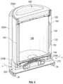
- FIG. 1is perspective front and top view of a cooler container.
- FIG. 2is a cross-sectional view of the cooler container in FIG. 1 along line 2 - 2 .
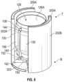
- FIG. 3is a partially assembled view of the cooler container of FIG. 1 , excluding the frame.
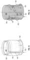
- FIG. 4is a partially assembled view of the cooler container of FIG. 1 , excluding the frame and outer vessel wall.
- FIG. 5is a cross-sectional view of the partial assembly in FIG. 4 along line 2 - 2 in FIG. 1 .
- FIG. 6is a cross-sectional view of the partial assembly in FIG. 4 along line 6 - 6 in FIG. 1 .
- FIG. 7is a perspective bottom view of a partial assembly of the cooler container of FIG. 1 , excluding the frame and outer vessel wall.
- FIG. 8is a perspective view of a partial assembly of the cooler container of FIG. 1 , excluding the frame and outer vessel wall.
- FIG. 9is a perspective view of a partial assembly of the cooler container of FIG. 1 , excluding the frame and outer vessel wall.
- FIG. 10is a cross-sectional view of the partial assembly in FIG. 9 , excluding the frame and outer vessel wall.
- FIG. 11is a perspective bottom view of the partial assembly in FIG. 9 , excluding the frame and outer vessel wall.
- FIG. 12is a partial perspective view of the partial assembly in FIG. 9 , excluding the frame and outer vessel wall.
- FIG. 13is a perspective top view of a component of the cooler container of FIG. 1 , excluding the frame and outer vessel wall and inner liner wall.
- FIG. 14is a perspective transparent view of the component in FIG. 13 , excluding the frame and outer vessel wall and inner liner wall.
- FIG. 15is a front view of a cooler container showing the display on a surface of the container.
- FIG. 16is a schematic view showing multiple cooler containers stacked on a pallet.
- FIG. 17shows a schematic illustration of stacked cooler containers.
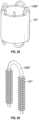
- FIG. 18shows a schematic perspective bottom view of a cooler container.
- FIG. 19shows a schematic view of stacked cooler containers on a charging base.
- FIG. 20shows a schematic partial perspective top view of the cooler container.
- FIG. 21shows a schematic perspective front view of the cooler container.
- FIG. 22is a schematic block diagram showing communication between the cooler container and a remote electronic device.
- FIG. 23is a schematic block diagram showing electronics in the cooler container associated with the operation of the display screen of the cooler container.
- FIGS. 24 A- 24 Bshow block diagrams of a method for operating the cooler container of FIG. 1 .
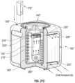
- FIG. 25is a schematic front partially exploded view of a cooler container.
- FIG. 26is a schematic view of a cooler container system.
- FIG. 27 Ais a schematic view of a cooler container system.
- FIG. 27 Bis a partial cutaway view of the cooler container system of FIG. 27 A .
- FIG. 27 Cis a partial cutaway view of an example cooler container system.
- FIG. 28is a schematic view of a portion of a cooler container system.
- FIG. 29is a schematic view of an example of a portion of a conduit of a cooler container system.
- FIG. 30is a schematic view of an example of a portion of a conduit of a cooler container system.
- FIG. 31is a schematic view of an example of a portion of conduit of a cooler container system.
- FIG. 32is a schematic view of an example of a portion of a cooler container system.
- FIG. 33is a schematic cross-sectional view of a cooler container.
- FIG. 34is a schematic side view of a cooler container.
- FIG. 35is a schematic side view of a cooler container.
- FIG. 36 Ais a schematic view of an electrical connector of a cooler container.
- FIG. 36 Bis a schematic view of an electrical connector of a cooler container.
- FIG. 37is a schematic side view of a cooler container.
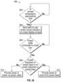
- FIG. 38shows an example process for operating the cooler container.
- FIG. 39is a schematic side view of a cooler container.
- FIG. 40is a schematic side view of a cooler container.
- FIG. 41 Ais a schematic front view of a wall or tower that transfers power to the containers.
- FIG. 41 Bis a schematic side view of multiple cooler containers proximate the wall or tower of FIG. 41 A that transfers power to the containers.
- FIG. 42 Ais a schematic diagram of electronics of the cooler container of FIG. 39 .
- FIG. 42 Bis a schematic diagram of electronics of the cooler container of FIG. 40 .
- FIG. 43is a schematic diagram of electronics of the power and data unit of FIGS. 41 A- 41 B .
- FIGS. 1 - 23illustrate a cooler container assembly 1000 (the “assembly”), or components thereof. Though the features below are described in connection with the cooler container assembly 1000 , the features also apply to all cooler containers, such as cooler containers 1000 ′, 1000 ′′, 1000 ′′′ disclosed herein.
- the assembly 1000can include a container vessel 100 , a frame 300 coupled to the container vessel 100 , and a lid 400 removably coupleable to a top end T of the container vessel 100 .
- the lid 400can be a double-walled vacuum lid.
- the frame 300can have a rectangular shape (e.g., a square shape) with two or more (e.g., four) pillars 301 .
- the frame 300can have other suitable shapes (e.g., cylindrical).
- the frame 300optionally defines one or more openings or open spaces 302 between the frame 300 and the container vessel 100 , allowing air to pass or flow through said openings or spaces 302 (e.g., even when multiple cooler container assemblies 1000 are stacked on top of and beside each other, as shown in FIG. 16 ).
- a lower surface 307 of the frame 300can have one or more air intake openings 203 (e.g., an intake grill). As shown in FIG. 1 , the air intake openings 203 can be arranged around at least a portion of (e.g., around an entirety of) the periphery of the container vessel 100 .
- An upper surface 304 of the frame 300can have one or more distal vent openings 205 A.
- FIG. 1shows two distal vent openings 205 A, though more or fewer openings 205 A can be provided in other implementations.
- the exhaust vent opening(s) 205 Acan optionally have a curved shape (e.g., semicircular shape).
- the upper surface 304 of the frame 300can have one or more electrical contacts 32 (e.g., contact pads, curved contacts). Optionally, the electrical contacts 32 can be recessed relative to the upper surface 304 . In the implementation shown in FIG.
- the frame 300has two distal vent openings 205 A disposed near opposite corners of the frame 300 , and two electrical contacts 32 disposed near opposite corners of the frame 300 , each electrical contact 32 interposed between the two distal vent openings 205 A along a plane that defines the upper surface 304 .
- the frame 300has a bottom surface (e.g., underside surface) 306 that also has one or more proximal vent openings 205 B (see FIG. 6 ) that fluidly communicate with the distal vent opening(s) 205 A.
- the bottom surface 306also has one or more electrical contacts 34 (see FIG. 5 ).
- the electrical contacts 34e.g., pin contacts, Pogo pins, contact pads
- the electrical contacts 34 on the bottom surface 306 of one frame 300will contact the electrical contacts 32 on the top surface 304 of an adjacent frame 300 to thereby provide an electrical connection between the adjacent cooler container assemblies 1000 .
- proximal vent openings 205 B on the bottom surface 306 of one framewith substantially align with distal vent openings 205 A of an adjacent frame 300 to thereby provide fluid communication (e.g., a flow path, a chimney path) between the adjacent cooler container assemblies 1000 (see FIG. 17 ).
- fluid communicatione.g., a flow path, a chimney path
- the cooler container assembly 1000also includes a display screen 188 .
- FIG. 1shows the display screen 188 on the container vessel 100 , it can alternatively (or additionally) be incorporated into the frame 300 and/or lid 400 .
- the display screen 188can optionally be an electronic ink or E-ink display (e.g., electrophoretic ink display).
- the display screen 188can be a digital display (e.g., liquid crystal display or LCD, light emitting diode or LED, etc.).
- the display screen 188can display a label 189 , as shown in FIG.
- the display screen 188can display an advertisement (e.g., for one or more of the payload components, for example, read by an RFID reader of the container 1000 , 1000 ′, 1000 ′′, 1000 ′′′), as further discussed herein.
- the cooler container assembly 1000can optionally also include a user interface 184 .
- the user interface 184is on the upper surface 304 of the frame 300 .
- the user interface 184is disposed on the container vessel 100 and/or lid 400 .
- the user interface 184is optionally a button (e.g., a “return home” button).
- the user interface 184is a depressible button.
- the user interface 184is a capacitive sensor (e.g., touch sensitive sensor, touch sensitive switch).
- the user interface 184is a sliding switch (e.g., sliding lever).
- the user interface 184is a rotatable dial.
- the user interface 184can be a touch screen portion (e.g., separate from or incorporated as part of the display screen 188 ).
- actuation of the user interface 184can alter the information shown on the display 188 , such as the form of a shipping label shown on an E-ink display 188 .
- actuation of the user interface 184can switch the text associated with the sender and receiver, allowing the cooler container assembly 1000 to be shipped back to the sender once the receiving party is done with it.
- actuation of the user interface 184causes a signal to be sent by circuitry in the assembly 1000 , as further discussed below, to a shipping carrier (e.g., UPS, FedEx, DHL) informing the shipping carrier that a shipping label (e.g., new shipping label) has been assigned to the portable cooler and that the cooler is ready for pick-up and shipping.
- a shipping carriere.g., UPS, FedEx, DHL
- a shipping labele.g., new shipping label
- FIG. 2shows a cross-sectional view of the cooler container assembly 1000 along line 2 - 2 in FIG. 1 .
- the assembly 100can optionally have one or more feet 303 that protrude from the bottom surface 306 can facilitate the positioning and/or interlocking of one assembly 1000 on top of another assembly 1000 when stacking them together.
- the container vessel 100can have a chamber 126 defined by an inner wall 126 A and a base wall 126 B and sized to removably hold one or more materials or products to be cooled (e.g., solids, liquids, food, beverages, medicines, living organisms or tissue).
- the chamber 126can in one implementation be cylindrical.
- the assembly 1000also includes a cooling system 200 .
- the cooling system 200can optionally be at least partially housed in the vessel container 100 .
- the cooling system 200can be housed below the chamber 126 (e.g., in one or more cavities between the base wall 126 B and the bottom end B of the cooler container assembly 1000 ).
- the cooling system 200can include a first heat sink 210 (e.g., a cold side heat sink), one or more thermoelectric modules or TEC (e.g., Peltier elements) 220 , and a second heat sink 230 (e.g., a hot side heat sink).
- the one or more thermoelectric modules (e.g., Peltier elements) 220can be interposed between (e.g., in thermal communication with, in thermal contact with, in direct contact with) the first heat sink 210 and the second heat sink 230 .
- the cooling system 200can optionally include a fan 280 in fluid communication with the second heat sink 230 , the fan 280 selectively operable to flow air past the second heat sink 230 to effect heat transfer from the second heat sink 230 (e.g., to remove heat from the hot side heat sink 230 ).
- the cooling system 200can include one or more fans 216 in fluid communication with the first heat sink 210 , the fan(s) 216 selectively operable to flow air past the first heat sink 210 to effect heat transfer with the first heat sink 210 (e.g., to allow the cold side heat sink 210 to remove heat from the air flowing past the heat sink 210 ). In the implementation shown in FIGS.
- two fans 216 A, 216 Bare in fluid communication with the first heat sink 210 .
- the fans 216 A, 216 Bare operable to flow air in the same direction. However, more or fewer fans 216 can be utilized, and can operate in series or parallel to provide air flow.
- the fans 216 A, 216 Bare axial fans. In another example, the fans 216 A, 216 B can be centrifugal fans or radial fans. Other types of fans can be used.
- the cooling system 200can flow (e.g., circulate) cooled air cooled by the first heat sink 210 into a channel 107 defined between the inner wall 126 A and a second wall 106 (e.g., inner liner wall), the cooled air cooling the inner wall 126 A and thereby cooling the chamber 126 and the contents in the chamber 126 .
- a second wall 106e.g., inner liner wall
- the cooling system 200exhausts air that flows past the second heat sink 230 (e.g., heated air that has removed heat from the hot side heat sink 230 ) via air vent assemblies 202 A, 202 B, where said air enters channels 206 A, 206 B in the exhaust assemblies 202 A, 202 B via one or more openings 204 A, 204 B, where the exhausted air travels upward along the channels 206 A, 206 B and exits the cooler container assembly 1000 via the distal vent openings 205 A.
- the second heat sink 230e.g., heated air that has removed heat from the hot side heat sink 230
- air vent assemblies 202 A, 202 Bwhere said air enters channels 206 A, 206 B in the exhaust assemblies 202 A, 202 B via one or more openings 204 A, 204 B, where the exhausted air travels upward along the channels 206 A, 206 B and exits the cooler container assembly 1000 via the distal vent openings 205 A.
- the channels 206 A, 206 Bextend to the proximal vent openings 205 A, 205 B, thereby allowing air from a lower assembly 1000 to also pass through the channels 206 A, 206 B and exit via the distal vent openings 205 A, 205 B. Accordingly, when the assemblies 1000 are stacked on top of each other, the channels 206 A, 206 B align to allow for (hot) air to exhaust the stacked assemblies 1000 in a chimney-like manner (See FIG. 17 ). As shown in FIG.
- intake air Iflows (e.g., via openings 203 ) into the assembly 1000 (e.g., via operation of the fan 280 ) and into fluid contact with the second heat sink 230 , after which the exhaust air E is vented via the channels 206 A, 206 B and distal vent openings 205 A.
- the container vessel 100can include one or more sleeve portions 130 defined between a third wall 132 and the second wall 106 (e.g., inner liner wall).
- the one or more sleeve portions 130can optionally be discrete volumes disposed about at least a portion of the circumference of the second wall 106 .
- the one or more sleeve portions 130can house a phase change material (PCM) 135 or thermal mass therein.
- the phase change material 135can be a solid-liquid PCM.
- the phase change material 135can be a solid-solid PCM.
- the PCM 135advantageously can passively absorb and release energy.
- PCM materialsexamples include water (which can transition to ice when cooled below the freezing temperature), organic PCMs (e.g., bio based or Paraffin, or carbohydrate and lipid derived), inorganic PCMs (e.g., salt hydrates), and inorganic eutectics materials.
- organic PCMse.g., bio based or Paraffin, or carbohydrate and lipid derived
- inorganic PCMse.g., salt hydrates
- inorganic eutectics materialsexamples include water (which can transition to ice when cooled below the freezing temperature), organic PCMs (e.g., bio based or Paraffin, or carbohydrate and lipid derived), inorganic PCMs (e.g., salt hydrates), and inorganic eutectics materials.
- the PCM 135can be any thermal mass that can store and release energy.
- the cooling system 200can be operated to cool the first heat sink 210 to cool the chamber 126 .
- the cooling system 200can optionally also cool the PCM 135 (e.g., via the second wall 106 as cooled air/coolant flows through the channel 107 ) to charge the PCM 135 (e.g., to place the PCM 135 in a state where it can absorb energy).
- one or more finscan extend from the second wall 106 (e.g., into the volume of the sleeve portion(s) 130 ), for example to enhance heat transfer to the PCM 135 .
- the PCM 135operates as a passive (e.g., backup) cooling source for the chamber 126 and contents disposed in the chamber 126 .
- the PCM 135can maintain the chamber 126 and contents in the chamber 126 in a cooled state until the active cooling system can once again operate to cool the chamber 126 and contents therein.
- the container vessel 100can include a fourth wall 104 (e.g., outer liner wall) that defines an annular channel 105 between the second wall 106 (e.g., inner liner wall).
- the annular channel 105can be under negative pressure (e.g. vacuum), thereby advantageously inhibiting heat transfer with the cooled air flowing through the annular channel 105 to inhibit (e.g., prevent) loss of cooling power and/or improve the efficiency of the cooling loop.
- An outer vessel wall 102is disposed about the fourth wall 104 .
- An inlet line (e.g., cool air inlet line, tube, pipe or conduit) 140can have a proximal end 142 in fluid communication with one end 215 A of a cold air fluid chamber 215 and extend to a distal end 144 in communication with the channel 107 between the inner wall 126 A and the second wall (e.g., inner liner wall) 106 .
- An outlet line (e.g., cool air exhaust line, tube, pipe or conduit) 150can have a proximal end 152 in communication with the channel 107 between the inner wall 126 A and the second wall 106 and extend to a distal end 154 in fluid communication with an opposite end 215 B of the cold air fluid chamber 215 .
- the cold air fluid chamber 215 , inlet line 140 , outlet line 150 and channel 107defines a closed system via which a cooled fluid (e.g., cooled air, a cooled liquid coolant) is passed to cool the inner wall 126 A and thereby the chamber 126 .
- a cooled fluide.g., cooled air, a cooled liquid coolant
- the air vent assemblies 202 A, 202 Bare arranged about the fourth wall 104 (e.g., outer liner wall), with a gap or channel 103 defined between the air vent assemblies 202 A, 202 B (see FIGS. 3 - 4 ).
- the fans 216 A, 216 Boperate to drive air past the first heat sink 210 (e.g., cold side heat sink to cool said air) and the air is then directed via the proximal end 142 into the inlet line 140 (e.g., in direction F in FIGS. 2 , 12 ).
- the airflows up the inlet line 140 and exits via the distal end 144 into the channel 107 on one side of dividing wall 109 (see FIG. 8 ) that extends between the inner wall 126 A and the second wall (e.g., inner liner wall) 106 .
- the airthen travels within the channel 107 around the circumference of the inner wall 126 A until it reaches the dividing wall 109 , where it exits the channel via the proximal end 152 of the outlet line 150 .
- the airexits the outlet line 150 at the distal end 154 and into the opposite end 215 B of the cool air fluid chamber 215 , where the air is again driven by the fans 216 A, 216 B over the first heat sink 210 (e.g., cold side heat sink 210 to cool the air) and again circulated via the inlet line 140 into the channel 107 .
- the first heat sink 210e.g., cold side heat sink 210 to cool the air
- valvescan be used to regulate the flow of cooled fluid (e.g., air, another gas, liquid) during active cooling mode as well as control convection thermal ingress when the cooler 1000 is operating in passive cooling mode (e.g., when the fans 216 A, 216 B are not operating, when the PCM 135 is providing the cooling function, etc.).
- the dividing wall 109advantageously forces the cooled air to circulate along substantially the entire surface (e.g., substantially entire circumference) of the chamber 126 (e.g., along path C in FIG.
- one or more finscan extend from the second wall 106 into the channel 107 (e.g., along the direction of air flow in the channel 107 ), for example to enhance heat transfer to the inner wall 126 A and/or chamber 126 .
- the cool air fluid chamber 215is separated from the hot air fluid chamber 218 (see FIGS. 5 - 6 ).
- thermally insulative materialcan be interposed between the cool air fluid chamber 215 and the hot air fluid chamber 218 .
- the assembly 1000can include electronics (e.g., at least partially in a cavity below the base wall 126 B, between the base wall 126 B and the bottom B of the assembly 1000 ) operable to control the operation of the fans 280 , 216 A, 216 B, thermoelectric module(s) (TECs) 220 , and display 188 .
- the electronicscan include circuitry (e.g., control circuitry, one or more processors on a printed circuit board, a CPU or central processing unit, sensors) that controls the operation of the cooling system 200 , and optionally one or more batteries to provide power to one or more of the circuitry, fans 280 , 216 A, 216 B, regulating valves and thermoelectric module(s) (TECs) 220 .
- the assembly 1000can optionally have a power button or switch actuatable by a user to turn on or turn off the cooling system.
- the bottom B of the assembly 1000defines at least a portion of an end cap that is removable to access the electronics (e.g., to replace the one or more batteries, perform maintenance on the electronics, such as the PCBA, etc.).
- the power button or switchis accessible by a user (e.g., can be pressed to turn on the cooling system 200 , pressed to turn off the cooling system 200 , optionally pressed to pair the cooling system 200 with a mobile electronic device, etc.).
- the power switchcan be located generally at the center of the end cap (e.g., so that it aligns/extends along the symmetrical axis of the container vessel 100 ).
- FIG. 18shows an example bottom view of the cooler container assembly 1000 , showing the proximal vent openings 205 B that communicate with the channels 206 A, 206 B of the air vent assemblies 202 A, 202 B.
- FIG. 18also shows the electrical contacts 34 on the bottom surface 306 of the cooler container assembly 1000 .
- the proximal vent openings 205 Bprotrude from the bottom surface 306 of the assembly 1000 , allowing them to extend into the corresponding proximal openings 205 A on the top surface 302 of the assembly 1000 .
- the electrical contacts 34protrude from the bottom surface 306 of the assembly 1000 , allowing them to extend into corresponding openings for the electrical contacts 32 on the top surface 302 of the assembly 1000 .
- FIG. 19shows multiple cooler container assemblies 1000 stacked on top of each other.
- the bottom of the assemblies 1000can be placed on a power base or charging base 500 .
- the electrical contacts 32 , 34 of the assemblies 1000allows power to be transferred from one assembly 1000 to the assembly 1000 above it, allowing each of the assemblies 1000 in the stack to receive power from the single charging base 500 , advantageously allowing the assemblies 1000 to be powered (e.g., their batteries charged) at the same time.
- the charging base 500can have a platform or base 510 optionally coupled to an electrical cord 512 (e.g., which can be connected to wall power or a portable power source, such as a power source in a trailer, truck, boat, airplane or other transportation unit).
- the base 510can have one or more charging units 520 (e.g., two charging units 520 A, 520 B).
- the charging units 520can optionally have one or more connectors 505 sized and/or shaped to interface with the proximal vent openings 205 B.
- the charging units 520can optionally have one or more electrical contacts 534 sized and/or shaped to interface with the electrical contacts 34 on the bottom of the cooler container assembly 1000 .
- the connectors 505 and electrical contacts 534can have a curved shape. In one example, the connectors 505 and electrical contacts 534 together generally define a circular shape (e.g., generally corresponding to a generally circular shape defined by the electrical contacts 34 and proximal vent openings 205 B on the bottom surface 306 of the assembly 1000 ).
- the display 188 of each of the assemblies 1000 in the stackcan display the charging status (e.g., % charge, charge level, time remaining during which cooling system 200 can operate, etc.) of one or more batteries in the corresponding assembly 1000 .
- the display 188 of each of the assemblies 1000can indicate (e.g., via a visual and/or audio signal) when its corresponding batteries are fully charged.
- FIG. 20shows a top surface 302 of the cooler container assembly 1000 , which can optionally include an indicator light 195 to indicate one or more of: the assembly 1000 is on, the lid 400 is closed correctly (e.g., via a signal from one or more sensors, such as proximity sensors, capacitance sensors, etc. send to the control circuitry of the assembly 1000 ), and the cooling system 200 is in operation (e.g., to cool the chamber 126 ).
- an indicator light 195to indicate one or more of: the assembly 1000 is on, the lid 400 is closed correctly (e.g., via a signal from one or more sensors, such as proximity sensors, capacitance sensors, etc. send to the control circuitry of the assembly 1000 ), and the cooling system 200 is in operation (e.g., to cool the chamber 126 ).
- FIG. 21shows a button 187 on a front of the assembly 1000 (e.g., located below the display 188 ).
- the button 187can be actuated (e.g., by a user) to display the battery level of the assembly 1000 (e.g., % charge, charge level, time remaining during which cooling system 200 can operate, etc.).
- the button 187can be located elsewhere on the assembly 1000 .
- the button 187can be a depressible button or a touch switch (e.g., capacitance) sensor.
- FIG. 22shows a block diagram of a control system for (e.g., incorporated into) the devices described herein (e.g., the cooler container assembly 1000 , 1000 ′, 1000 ′′, 1000 ′′′).
- circuitry EMe.g., control circuitry, microcontroller unit MCU, computer processor(s), etc.
- can receive sensed information from one or more sensors S 1 -Sne.g., level sensors, volume sensors, temperature sensors, pressure sensors, orientation sensors such as gyroscopes, accelerometers, battery charge sensors, biometric sensors, load sensors, Global Positioning System or GPS sensors, radiofrequency identification or RFID reader, etc.
- sensors S 1 -Sne.g., level sensors, volume sensors, temperature sensors, pressure sensors, orientation sensors such as gyroscopes, accelerometers, battery charge sensors, biometric sensors, load sensors, Global Positioning System or GPS sensors, radiofrequency identification or RFID reader, etc.
- At least one temperature sensor Sn(e.g., Sn1, Sn2 and/or Sn3) is in the vessel 100 , 100 ′, 100 ′′′ or lid 400 , 400 ′, 400 ′′′ and exposed to the chamber 126 , 126 ′′′ to sense a temperature in the chamber 126 , 126 ′′′.
- at least one temperature sensor Sn, Ta(see FIG. 27 A ) is on the vessel 100 , 100 ′, 100 ′′′ or lid 400 , 400 ′, 400 ′′′ and exposed to the outside of the container 1000 , 1000 ′, 1000 ′′, 1000 ′′′ to measure ambient temperature.
- the RFID reader in the vessel 100 , 100 ′, 100 ′′′ or lid 400 , 400 ′, 400 ′′′can read RFID tags of components (e.g., medication, vials, liquid containers, food packages) placed in the chamber 126 , 126 ′′′.
- the RFID readercan optionally log when the payload contents are inserted into the chamber 126 , 126 ′′′, and additionally or alternatively the RFID reader can optionally log when each of the one or more of the payload contents is removed from the chamber 126 , 126 ′′′ to track their position relative to the vessel 100 , 100 ′, 100 ′′′ and communicate this information to the circuitry EM (e.g., to a memory of the circuitry EM).
- one or more of the sensors S 1 -Sncan include a pressure sensor.
- the pressure sensorcan optionally sense ambient pressure, which can be indicative of an altitude of the cooler container assembly 1000 , 1000 ′, 1000 ′′, 1000 ′′′.
- the pressure sensorcommunicates sensed pressure information to the circuitry EM, which can optionally log or record the data from the pressure sensor and/or can operate one or more components of the cooling system 200 , 200 ′′, such as the TECs 220 , 220 ′′ and fan(s) 280 , 280 ′′ based at least in part on the sensed pressure information from the pressure sensor (e.g., to maintain the chamber 126 , 126 ′, 126 ′′ at a desired temperature or temperature range).
- Such pressure sensor(s)can advantageously allow the cooling system 200 , 200 ′′ to operate such that the chamber 126 , 126 ′, 126 ′′ is at a desired temperature or temperature range while the cooler container assembly 1000 , 1000 ′, 1000 ′′, 1000 ′′′ in transit (e.g., in high altitude locations), such as on an airplane or truck.
- one or more of the sensors S 1 -Sncan include an accelerometer.
- the accelerometercan optionally sense motion (e.g., sudden movement) of the cooler container assembly 1000 , 1000 ′, 1000 ′′, 1000 ′′′.
- the accelerometercommunicates with the circuitry EM, which can optionally log or record the data from the accelerometer and/or can operate one or more components of the cooling system 200 , 200 ′′, such as the TECs 220 , 220 ′′ and fan(s) 280 , 280 ′′ based at least in part on the sensed information from the accelerometer.
- Such accelerometer(s)can advantageously sense, for example, when the cooler container assembly 1000 , 1000 ′, 1000 ′′, 1000 ′′′ has been dropped (e.g., from an unsafe height) or experienced a shock, for example while in transit, such as on an airplane or truck.
- the accelerometercan also provide the circuitry EM with sensed orientation information of the cooler container assembly 1000 , 1000 ′, 1000 ′′, 1000 ′′′.
- a separate orientation sensore.g., a gyroscope
- the circuitry EMcan optionally log or record the data from the orientation sensor and/or can operate one or more components of the cooling system 200 , 200 ′′, such as the TECs 220 , 220 ′′ and fan(s) 280 , 280 ′′ based at least in part on the sensed orientation information.
- the circuitry EMcan be housed in the container vessel 100 .
- the circuitry EMcan receive information from and/or transmit information (e.g., instructions) to one or more heating or cooling elements HC, such as the TEC 220 (e.g., to operate each of the heating or cooling elements in a heating mode and/or in a cooling mode, turn off, turn on, vary power output of, etc.) and optionally to one or more power storage devices PS (e.g., batteries, such as to charge the batteries or manage the power provided by the batteries to the one or more heating or cooling elements).
- informatione.g., instructions
- one or more heating or cooling elements HCsuch as the TEC 220
- PSe.g., batteries, such as to charge the batteries or manage the power provided by the batteries to the one or more heating or cooling elements.
- the circuitry EMcan include a wireless transmitter, receiver and/or transceiver to communicate with (e.g., transmit information, such as sensed temperature and/or position data, to and receive information, such as user instructions from) one or more of: a) a user interface UI 1 on the unit (e.g., on the body of the container vessel 100 or frame 300 ), b) an electronic device ED (e.g., a mobile electronic device such as a mobile phone, PDA, tablet computer, laptop computer, electronic watch, a desktop computer, remote server, cloud server), c) via the cloud CL, or d) via a wireless communication system such as WiFi, broadband network and/or Bluetooth BT.
- a wireless communication systemsuch as WiFi, broadband network and/or Bluetooth BT.
- the circuitry EMcan have a cell radio antenna or cell radio via which it can communicate information (e.g., GPS location, sensed temperature in the chamber, ambient temperature, etc.) wirelessly (e.g., to the cloud CL, to a remote electronic device, such as a smartphone, etc.).
- informatione.g., GPS location, sensed temperature in the chamber, ambient temperature, etc.
- a remote electronic devicesuch as a smartphone, etc.
- a usercan then track a location of the container 1000 , 1000 ′, 1000 ′′, 1000 ′′′ (e.g., via a website or app on a smartphone).
- the circuitry EMcan report data sensed by one or more of the sensors S 1 -Sn (e.g., sensed ambient temperature, sensed temperature in the chamber 126 , 126 ′′, sensed pressure, sensed humidity outside the chamber 126 , 126 ′′, sensed humidity inside the chamber 126 , 126 ′′), for example wirelessly, to a remote electronic device or the cloud CL (e.g., transmit a report to a pharmacy or medical institution with a log temperature, pressure and/or humidity information of the contents of the container 1000 , 1000 ′, 1000 ′′, 1000 ′′′ during transit to said pharmacy or medical institution).
- a remote electronic device or the cloud CLe.g., transmit a report to a pharmacy or medical institution with a log temperature, pressure and/or humidity information of the contents of the container 1000 , 1000 ′, 1000 ′′, 1000 ′′′ during transit to said pharmacy or medical institution.
- the containers 1000 , 1000 ′, 1000 ′′, 1000 ′′′When the containers 1000 , 1000 ′, 1000 ′′, 1000 ′′′ are stacked, they can set up a MESH network (e.g., a meshnet via BLE 5 . 0 ), which would allow the containers 1000 , 1000 ′, 1000 ′′, 1000 ′′′ at the top of the stack to communicate (via the cell radio or cell radio antenna) GPS location and/or sensed temperature data for each of the stacked containers 1000 , 1000 ′, 1000 ′′, 1000 ′′′.
- the MESH networkcan optionally identify the container 1000 , 1000 ′, 1000 ′′, 1000 ′′′ with the most available power to communicate the GPS location and/or sensed temperature data.
- the electronic device EDcan have a user interface UI 2 , that can display information associated with the operation of the cooler container assembly 1000 , 1000 ′, 1000 ′′, 1000 ′′′, and that can receive information (e.g., instructions) from a user and communicate said information to the cooler container assembly 1000 , 1000 ′, 1000 ′′, 1000 ′′′ (e.g., to adjust an operation of the cooling system 200 ).
- UI 2user interface
- the electronic device EDcan have a user interface UI 2 , that can display information associated with the operation of the cooler container assembly 1000 , 1000 ′, 1000 ′′, 1000 ′′′, and that can receive information (e.g., instructions) from a user and communicate said information to the cooler container assembly 1000 , 1000 ′, 1000 ′′, 1000 ′′′ (e.g., to adjust an operation of the cooling system 200 ).
- the cooler container assembly 1000 , 1000 ′, 1000 ′′can operate to maintain the chamber 126 of the container vessel 100 at a preselected temperature or a user selected temperature.
- the cooling systemcan operate the one or more TECs 220 , 220 ′′ to cool the chamber 126 , 126 ′′ (e.g., if the temperature of the chamber is above the preselected temperature, such as when the ambient temperature is above the preselected temperature or temperature range, for example when transporting of medication in summer or to very hot climate location) or to heat the chamber 126 , 126 ′′ (e.g., if the temperature of the chamber 126 is below the preselected temperature, such as when the ambient temperature is below the preselected temperature or temperature range, for example when transporting of medication in winter or to very cold climate location).
- the circuitry EMcan reverse the polarity of the TECs 220 , 220 ′′ and operate the TECs 220 , 220 ′′ to heat the chamber 126 , 126 ′′ (e.g., by heating a fluid circulating via a conduit in thermal communication with a phase change material or thermal mass to heat it, which in turn heats the chamber 126 , 126 ′′).
- such reversing of the polarity of the TECs 220 , 220 ′′ to heat the chamber 126 , 126 ′′inhibits (e.g., prevents) one or more of the payload components (e.g., medicine, vaccines, perishable liquids or solids) from freezing.
- the payload componentse.g., medicine, vaccines, perishable liquids or solids
- a predetermined temperaturee.g., 2 degrees C.
- a temperature sensore.g., Ta in FIG.
- the circuitry EMcan reverse the polarity of the TECs 220 , 220 ′′ and operate them to heat the chamber 126 , 126 ′′ as discussed above.
- the circuitry EMcan stop operation of the TECs 220 , 220 ′′ to heat the chamber 126 , 126 ′′ and/or reverse the polarity of the TECs 220 , 220 ′′ to their original state (e.g., a state in which the TECs 220 , 220 ′′ can operate to cool the chamber 126 , 126 ′′).
- the cooler container 1000 ′′can have one or more removable batteries PS′′, which can be installed in the cooler container 1000 ′′ (e.g., via opening 305 ′′) to power the TECs 220 , 220 ′′ in the reversed polarity state to heat the chamber 126 , 126 ′′.
- the circuitry EM and TECs 220 , 220 ′′can be operated with power from the one or more removable batteries PS′′, instead of other batteries (PS, PS′), which power other components of the cooler container assembly 1000 , 1000 ′, 1000 ′′ when the circuitry EM needs to operate the TECs 220 to heat the chamber 126 , 126 ′′ (e.g., when sensed ambient and/or chamber temperature falls below a predetermined temperature).
- the one or more batteries PS′′can optionally only be installed in the cooler container assembly 1000 , 1000 ′, 1000 ′′, 1000 ′′′ when they are to be shipped to a climate where ambient temperature is likely to drop below a first predetermined temperature (e.g. 2 degrees C.) and/or when they are to be shipped to a climate where ambient temperature is likely to increase above a second predetermined temperature (e.g., 15 degrees C., 20 degrees C., 30 degrees C., etc.).
- the one or more batteries PS′′can be installed in the cooler container assembly 1000 , 1000 ′, 1000 ′′, 1000 ′′′ for all shipments, irrespective of expected ambient temperature.
- the preselected temperaturemay be tailored to the contents of the container (e.g., a specific medication, a specific vaccine, food, beverages, human tissue, animal tissue, living organisms), and can be stored in a memory of the assembly 1000 , and the cooling system or heating system, depending on how the temperature control system is operated, can operate the TEC 220 to approach the preselected or set point temperature.
- the circuitry EM of the cooler container 1000 , 1000 ′, 1000 ′′, 1000 ′′′can communicate (e.g., wirelessly) information to a remote location (e.g., cloud-based data storage system, remote computer, remote server, mobile electronic device such as a smartphone or tablet computer or laptop or desktop computer) and/or to the individual carrying the container (e.g., via their mobile phone, via a visual interface on the container, etc.), such as a temperature history of the chamber 126 to provide a record that can be used (e.g., to evaluate the efficacy of the medication in the container, to evaluate if contents in the chamber 126 have spoiled, etc.) and/or alerts on the status of the chamber 126 and/or contents in the chamber 126 .
- a remote locatione.g., cloud-based data storage system, remote computer, remote server, mobile electronic device such as a smartphone or tablet computer or laptop or desktop computer
- the individual carrying the containere.g., via their mobile phone, via a visual interface on
- the temperature control systeme.g., cooling system, heating system
- the temperature control systemautomatically operates the TEC 220 to heat or cool the chamber 126 of the container vessel 100 to approach the preselected temperature.
- the cooling system 200can cool and maintain one or both of the chamber 126 and the contents therein at or below 15 degrees Celsius, such as at or below 10 degrees Celsius (e.g., in the range of 2 degrees Celsius to 8 degrees Celsius), in some examples at approximately 5 degrees Celsius.
- the one or more sensors S 1 -Sncan include one more air flow sensors that can monitor airflow through one or both of the intake vent 203 and exhaust vent 205 , through the cold side fluid chamber 215 , inlet line 140 and/or outlet line 150 . If said one or more flow sensors senses that the intake vent 203 is becoming clogged (e.g., with dust) due to a decrease in air flow, the circuitry EM (e.g., on the PCBA) can optionally reverse the operation of the fan 280 for one or more predetermined periods of time to draw air through the exhaust vent 205 and exhaust air through the intake vent 203 to clear (e.g., unclog, remove the dust from) the intake vent 203 .
- the circuitry EMe.g., on the PCBA
- the circuitry EMcan additionally or alternatively send an alert to the user (e.g., via a user interface on the assembly 1000 , wirelessly to a remote electronic device such as the user's mobile phone) to inform the user of the potential clogging of the intake vent 203 , so that the user can inspect the assembly 1000 and can instruct the circuitry EM (e.g., via an app on the user's mobile phone) to run an “cleaning” operation, for example, by running the fan 280 in reverse to exhaust air through the intake vent 203 .
- an air filtercan optionally be placed underneath the intake grill/vent 203 .
- the one or more sensors S 1 -Sn of the cooler container 1000 , 1000 ′, 1000 ′′, 1000 ′′′can include one more Global Positioning System (GPS) sensors for tracking the location of the cooler container assembly 1000 , 1000 ′, 1000 ′′, 1000 ′′′.
- GPSGlobal Positioning System
- the location informationcan be communicated, as discussed above, by a transmitter (e.g., cell radio antenna or cell radio) and/or transceiver associated with the circuitry EM to a remote location (e.g., a mobile electronic device, a cloud-based data storage system, etc.).
- the GPS locationis communicated (e.g., automatically, not in response to a query or request) by the circuitry EM at regular intervals (e.g., every 10 minutes, every 15 minutes, etc.).
- the GPS locationis communicated by the circuitry EM upon receipt of a request or query, such as from the user (e.g., via an app or website via which the user can track the location of the cooler container 1000 , 1000 ′, 1000 ′′, 1000 ′′′).
- FIG. 23shows a block diagram of electronics 180 of the cooler container assembly 1000 , 1000 ′, 1000 ′′, 1000 ′′′.
- the electronics 180can include circuitry EM′ (e.g., including one or more processors on a printed circuit board).
- the circuitry EM′communicate with one or more batteries PS′, with the display screen 188 , 188 ′′′, and with the user interface 184 , 184 ′′′.
- a memory module 185is in communication with the circuitry EM′.
- the memory module 185can optionally be disposed on the same printed circuit board as other components of the circuitry EM′.
- the circuitry EM′optionally controls the information displayed on the display screen 188 , 188 ′′′.
- Informationcan be communicated to the circuitry EM′ via an input module 186 .
- the input module 186can receive such information wirelessly (e.g., via radiofrequency or RF communication, via infrared or IR communication, via WiFi 802.11, via BLUETOOTH®, etc.), such as using a wand (e.g., a radiofrequency or RF wand that is waved over the container assembly 1000 , 1000 ′, 1000 ′′, 1000 ′′′, such as over the display screen 188 , 188 ′′′, where the wand is connected to a computer system where the shipping information is contained).
- a wande.g., a radiofrequency or RF wand that is waved over the container assembly 1000 , 1000 ′, 1000 ′′, 1000 ′′′, such as over the display screen 188 , 188 ′′′, where the wand is connected to a computer system where the shipping information is contained.
- the informatione.g., shipping information for a shipping label to be displayed on the display screen 188 can be electronically saved in the memory module 185 ).
- the one or more batteries PS'can power the electronics 180 , and therefore the display screen 188 for a plurality of uses of the cooler container assembly 1000 , 1000 ′, 1000 ′′, 1000 ′′′ (e.g., during shipping of the container assembly 1000 up to one-thousand times).
- the electronics 180can wirelessly communicate a signal to a shipping carrier (e.g., UPS, FedEx, DHL) informing the shipping carrier that a shipping label (e.g., new shipping label) has been assigned to the portable cooler and that the cooler is ready for pick-up and shipping (e.g., when the user interface 184 is actuated by the user).
- a shipping carriere.g., UPS, FedEx, DHL
- a shipping labele.g., new shipping label
- FIG. 24 Ashows a block diagram of one method 800 for shipping the cooler container assembly 1000 , 1000 ′, 1000 ′′, 1000 ′′′.
- one or more componentse.g., food(s), beverage(s), medicine, living tissue or organisms
- the lid 400is closed over the container vessel 100 once the contents have been placed therein.
- the lid 400is locked to the container vessel 100 , 100 ′, 100 ′ (e.g., via a magnetically actuated lock, including an electromagnet actuated when the lid 400 is closed that can be turned off with a code, such as a digital code, a code provided to a user's phone, etc.).
- informatione.g., shipping label information
- is communicatede.g., loaded onto
- a radiofrequency (RF) wandcan be waved over the container assembly 1000 , 1000 ′, 1000 ′′, 1000 ′′′ to transfer the shipping information to the input module 186 of the electronics 180 of the container assembly 1000 , 1000 ′, 1000 ′′, 1000 ′′′.
- the container assembly 1000 , 1000 ′, 1000 ′′, 1000 ′′′is shipped to the recipient (e.g., displayed on the shipping label 189 on the display screen 188 ).
- the assemblies 1000 , 1000 ′, 1000 ′′, 1000 ′′′can be stacked, for example on a pallet P, as shown in FIG. 16 , allowing hot air to be exhausted from the stacked assemblies 100 (using a chimney effect) as discussed above, allowing heated air to exit the stacked assemblies and, for example, be vented out of the shipping container via one or more vents in the shipping container.
- the stacked assemblies 1000 , 1000 ′, 1000 ′′, 1000 ′′′can be electrically connected, allowing power transfer between a lower assembly 1000 , 1000 ′, 1000 ′′, 1000 ′′′ to a higher assembly 1000 , 1000 ′, 1000 ′′, 1000 ′′′ (e.g., when all the assemblies are stacked on a power base or a charging base, such as prior to shipping in a warehouse or distribution center or during shipping if the shipping container has a power or charging base on which the assemblies 1000 are stacked).
- the assemblies 1000 , 1000 ′, 1000 ′′, 1000 ′′′ within the stackcan establish two-way communication link to transmit data, for example temperature history and battery consumption data.
- one of the cooler container assemblies 1000 , 1000 ′, 1000 ′′, 1000 ′′′is low on power, it can optionally draw power from one or more of the assemblies 1000 around it (e.g., above it, below it) when stacked.
- Cooling system 200 in individual cooler container assemblies 1000can optionally remain active when assemblies 1000 are stacked on a power base or charging base (such as charging base 500 in FIG. 19 ) to charge PCM 135 simultaneously, for example, at the warehouse or shipping facility, on a truck, ship, airplane, etc.
- FIG. 24 Bshows a block diagram of a method 800 ′ for returning the container assembly 1000 , 1000 ′, 1000 ′′, 1000 ′′′.
- the lid 400 , 400 ′′can be opened relative to the container vessel 100 .
- the lid 400 , 400 ′′is unlocked relative to the container vessel 100 (e.g., using a code, such as a digital code or RFID code on user's mobile phone, provided to the recipient from the shipper, via a keypad on the vessel 100 , 100 ′, 1000 ′′ or lid 400 , 400 ′′, 400 ′′′ and/or biometric identification).
- the user's smartphone or other electronic device with the unlock codecan be communicated to the container 1000 , 1000 ′, 1000 ′′, 1000 ′′′, for example, via Bluetooth or RFID, to unlock the lid 400 , 400 ′′, 400 ′′′ from the vessel 100 , 100 ′, 100 ′′′ (e.g., by positioning or waiving the smartphone or electronic device near the vessel and/or lid).
- the contentse.g., medicine, foodstuff, beverages, living organisms or tissue
- the lid 400is closed over the container vessel 100 .
- the user interface 184(e.g., button) is actuated to switch the information of the sender and recipient in the display screen 188 with each other, advantageously allowing the return of the container assembly 1000 , 1000 ′, 1000 ′′, 1000 ′′′ to the original sender to be used again without having to reenter shipping information on the display screen 188 , 188 ′′′.
- actuation of the user interface 184 , 184 ′′′ in step 880causes a signal to be wirelessly communicated (e.g., by the electronics 180 ) to a shipping carrier (e.g., UPS, FedEx, DHL) informing the shipping carrier that a shipping label (e.g., new shipping label) has been assigned to the portable cooler and that the cooler is ready for pick-up and shipping.
- a shipping carriere.g., UPS, FedEx, DHL
- the cooler container assembly 1000 , 1000 ′, 1000 ′′, 1000 ′′′ or stack of assemblies 1000 , 1000 ′, 1000 ′′, 1000 ′′′can also send notifications to both end-user as well as origin facility during certain events, for example, payload has been delivered or alerts as needed.
- the display screen 188 , 188 ′′′ and label 189advantageously facilitate the shipping of the container assembly 1000 without having to print any separate labels for the container assembly 1000 .
- the display screen 188 , 188 ′′′ and user interface 184 , 184 ′′′advantageously facilitate return of the container system 1000 to the sender (e.g. without having to reenter shipping information, without having to print any labels), where the container assembly 1000 , 1000 ′, 1000 ′′, 1000 ′′′ can be reused to ship contents again, such as to the same or a different recipient.
- the reuse of the container assembly 1000 , 1000 ′, 1000 ′′, 1000 ′′′ for delivery of perishable materialadvantageously reduces the cost of shipping by allowing the reuse of the container vessel 100 (e.g., as compared to commonly used cardboard containers, which are disposed of after one use).
- perishable materiale.g., medicine, food, beverages, living tissue or organisms
- FIG. 25shows a partially exploded view of a cooler container 1000 ′.
- Some of the features of the cooler container 1000 ′are similar to features of the cooler container 1000 in FIGS. 1 - 24 B .
- reference numerals used to designate the various components of the cooler container 1000 ′are identical to those used for identifying the corresponding components of the cooler container 1000 in FIGS. 1 - 24 B , except that a “′” has been added to the numerical identifier. Therefore, the structure and description for the various features of the cooler container 1000 and how it's operated and controlled in FIGS. 1 - 24 B are understood to also apply to the corresponding features of the cooler container 1000 ′ in FIG. 25 , except as described below. Though the features below are described in connection with the cooler container assembly 1000 ′, the features also apply to all cooler containers, such as cooler containers 1000 , 1000 ′′, 1000 ′′′ disclosed herein.
- the cooler container 1000 ′differs from the cooler container 1000 in that the one or more power storage devices (e.g., batteries) PS, PS′ are in a module 350 ′ that can be removably coupled to the cooler container 1000 ′.
- the power storage devices PS, PS′can optionally be arranged in one or more stacks on a platform 352 ′, and electrically connected to the electrical contacts 34 ′ underneath the platform 352 ′.
- the module 350 ′can optionally couple to the cooler container 1000 ′ (e.g., to the frame 300 ′ of the cooler container 1000 ′) so that the power storage devices PS, PS′ extend into compartments in the cooler container 1000 ′ (e.g., compartments in the frame 300 ′), and so that the platform 352 ′ is adjacent to or generally co-planar with the bottom surface 306 ′ of the frame 300 ′.
- the module 350 ′locks into place on the cooler container 1000 ′ (e.g., via a latch mechanism, such as a spring-loaded latch mechanism, threaded coupling, magnetic coupling, etc.).
- a latch mechanismsuch as a spring-loaded latch mechanism, threaded coupling, magnetic coupling, etc.
- the display 188 ′can optionally register (e.g., display) that the module 350 ′ is coupled and optionally show the charge level of the power storage devices PS, PS′ of the module 350 ′.
- Powercan be provided from the power storage devices PS, PS′ to the electronics (e.g., Peltier element 220 , fan 280 , circuitry EM) in the cooler container 1000 ′, for example, via electrical contacts between the module 350 ′ and the cooler container 1000 ′ (e.g., electrical contacts on the frame 300 ′ that contact electrical contacts of the module 350 ′).
- the electronicse.g., Peltier element 220 , fan 280 , circuitry EM
- the module 350 ′can be decoupled and removed from the cooler container 1000 ′ to replace the power storage devices PS, PS′, or to replace the module 350 ′. Therefore, the module 350 ′ can be interchangeable and/or replaceable.
- the power storage devices (e.g., batteries) PS, PS′ in the module 350 ′can optionally be charged (or recharged) while coupled to the cooler container 1000 ′.
- the module 350 ′can be detached from the cooler container 1000 ′ and charged (or recharged) separately on the charging station or base 500 before being coupled to the cooler container 1000 ′ as discussed above.
- FIG. 26shows a schematic view of a cooler container 1000 ′′.
- Some of the features of the cooler container 1000 ′′are similar to features of the cooler container 1000 in FIGS. 1 - 24 B and cooling container 1000 ′ in FIG. 25 .
- reference numerals used to designate the various components of the cooler container 1000 ′′are identical to those used for identifying the corresponding components of the cooler container 1000 in FIGS. 1 - 24 B and cooler container 1000 ′ in FIG. 25 , except that a “′′” has been added to the numerical identifier. Therefore, the structure and description for the various features of the cooler container 1000 ′′ and how it's operated and controlled in FIGS. 1 - 25 are understood to apply to the corresponding features of the cooler container 1000 ′′ in FIG. 26 , except as described below. Though the features below are described in connection with the cooler container assembly 1000 ′′, the features also apply to all cooler containers, such as cooler containers 1000 ′, 1000 , disclosed herein.
- the cooler container 1000 ′′can have one or more sleeve portions 130 ′′ disposed about the chamber 126 ′′ of the container 1000 ′′ that can be filled with temperature sensitive contents (e.g., medicine, vaccines, tissue).
- the sleeve portion(s) 130 ′′can optionally be discrete volumes disposed about the chamber 126 ′′.
- the sleeve portion(s) 130 ′′can house a phase change material (PCM) or thermal mass 135 ′′ therein.
- the phase change material 135 ′′can be a solid-liquid PCM.
- the phase change material 135 ′′can be a solid-solid PCM.
- the PCM 135 ′′advantageously can passively absorb and release energy.
- PCM materialsexamples include water (which can transition to ice when cooled below the freezing temperature), organic PCMs (e.g., bio based or Paraffin, or carbohydrate and lipid derived), inorganic PCMs (e.g., salt hydrates), and inorganic eutectics materials.
- organic PCMse.g., bio based or Paraffin, or carbohydrate and lipid derived
- inorganic PCMse.g., salt hydrates
- inorganic eutectics materialsexamples include water (which can transition to ice when cooled below the freezing temperature), organic PCMs (e.g., bio based or Paraffin, or carbohydrate and lipid derived), inorganic PCMs (e.g., salt hydrates), and inorganic eutectics materials.
- the PCM 135 ′′can be any thermal mass that can store and release energy.
- the cooler container 1000 ′′can optionally include a cooling system 200 ′′. In other examples, described below, at least a portion of the cooling system 200 ′′ can be external to the container 1000 ′′.
- the cooling system 200 ′′is optionally a closed loop system.
- the cooling system 200 ′′optionally includes a conduit 140 ′′ via which a cooling fluid (e.g., a cooling liquid, such as water) flows.
- a cooling fluide.g., a cooling liquid, such as water
- the cooling fluidcan be water.
- the cooling fluidcan be a water mixture (e.g., a water-alcohol mixture, a mixture of water and ethylene glycol, etc.).
- the cooling system 200 ′′can optionally include one or more of a first heat sink 210 ′′ (e.g., a solid to liquid heat exchanger), thermoelectric module(s) or TEC(s) 220 ′′, a second heat sink 230 ′′, fan(s) 280 ′′, a pump 146 ′′ and a reservoir 148 ′′.
- the conduit 140 ′′can include a first conduit 140 A′′ that extends between the first heat sink 210 ′′ and the sleeve portion(s) 130 ′′.
- the conduit 140 ′′also includes a second conduit 140 B′′ that extends through the sleeve portion(s) 130 ′′ and is in fluid communication with the first conduit 140 A′′.
- the reservoir 148 ′′is in fluid communication with an opposite end of the second conduit 140 B′′.
- the conduit 140 ′′also includes a third conduit 140 C′′ that extends between the reservoir 148 ′′ and the pump 146 ′′.
- the conduit 140 ′′also includes a fourth conduit 140 D′′ that extends between the pump 146 ′′ and the first heat sink 210 ′′.
- the TEC(s) 220 ′′are operated (as described above in connection with the cooling container 1000 , 1000 ′) to remove heat from the first heat sink 210 ′′ and transfer said heat to the second heat sink 230 ′′.
- the fan(s) 280 ′′are optionally operated to dissipate the heat from the second heat sink 230 ′′, thereby allowing the TEC(s) 220 ′′ to remove additional heat from the first heat sink 210 ′′ (e.g., to cool the first heat sink 210 ′′).
- the first heat sink 210 ′′(e.g., solid to liquid heat exchanger) can at least partially define one or more flow paths (e.g., in the body of the heat sink 210 ′′) in fluid communication with the first conduit 140 A′′ and fourth conduit 140 D′′.
- the pump 146 ′′can be selectively operated (e.g., by a controller of the cooling system 200 ′′ or container 1000 ′′) to flow the cooling fluid (e.g., liquid) through the conduit 140 ′′ and past or through the first heat sink 210 ′′ where the cooling fluid is cooled.
- the cooled cooling fluidis then directed through the first conduit 140 A′′ and into the sleeve(s) 130 ′′ via the second conduit 140 B′′ where the cooling fluid removes heat from the PCM 135 ′′ to thereby charge the PCM 135 ′′ (e.g., to place the PCM 135 ′′ in a state where it can absorb energy).
- the fluidthen exits the sleeve(s) 130 ′′ and flows into the reservoir 148 ′′. From the reservoir 148 ′′, the fluid flows via the third conduit 140 C′′ to the pump 146 ′′, where the pump 146 ′′ again pumps the liquid via the fourth conduit 140 D′′ past or through the first heat sink 210 ′′.
- the cooling fluide.g., liquid
- the second conduit 140 B′′ in the sleeve(s) 130 ′′extends in a coil like manner (e.g., in a spiral manner) through the sleeve(s) 130 ′′ to thereby increase the surface area of the second conduit 140 B′′ that contacts the PCM 135 ′′, thereby increasing the amount of heat transfer between the cooling fluid and the PCM 135 ′′.
- This configuration of the second conduit 140 B′′advantageously results in more rapid cooling/charging of the PCM 135 ′′.
- the chamber 126 ′′ of the cooler container 1000 ′′can be cooled to between about 2 and about 8 degrees Celsius (e.g., 0 degrees C., 1 degree C., 2 degrees C., 3 degrees C., 4 degrees C., 5 degrees C., 6 degrees C., 7 degrees C., 8 degrees C., 9 degrees C., 10 degrees C., etc.).
- the reservoir 148 ′′can have a valve (e.g., bleed valve) via which cooling fluid can be bled from the cooling system 200 ′′ or via which cooling fluid can be introduced into the cooling system 200 ′′.
- the cooler container 1000 ′′can optionally exclude batteries and electronics, such that the cooling system 200 ′′ does not operate while the cooler container 1000 ′′ is in transit (e.g., on a trailer, truck, airplane, boat, car, etc.). Rather, while in transit, the chamber 126 ′′ of the cooler container 1000 ′′ is cooled by the charged PCM 135 ′′ (e.g., the PCM 135 ′′ is the primary cooling mechanism for the chamber 126 ′′).
- the cooling system 200 ′can optionally be operated when the cooler container 1000 ′′ is placed on a power base (e.g., at a home shipping location, at a hospital, etc.).
- the cooler container 1000 ′′can have electrical contacts that selectively contact electrical contacts on a power base when the cooler container 1000 ′′ is placed on the power base.
- the power baseprovides power to one or more of the TEC(s) 220 ′′, pump 146 ′′, and fan(s) 280 ′′, which operate (e.g., by circuitry in the container 1000 ′′) as described above to charge the PCM 135 ′′.
- the cooler container 1000 ′′can be removed from the power base and the chamber 126 ′′ filled with temperature sensitive contents (e.g., medicine, vaccines, tissue, etc.), and the cooler container 1000 ′′ can be shipped to its destination, as described above.
- the charged PCM 135 ′′can operate to maintain the contents in the chamber 126 ′′ in a cooled state during transit of the cooler container 1000 ′′ to its destination.
- each cooler container 1000 ′′can optionally be stacked on top of each other, with the bottom cooler container 1000 ′′ disposed on the power base, so that power is transferred from the power base up through the stack of cooler containers 1000 ′′ (e.g., the PCM 135 ′′ in all stacked containers 1000 ′′ are charged substantially simultaneously).
- each cooler container 1000 ′′has an amount of cooling fluid in its closed loop cooling system 200 ′′ and power is transferred from each container 1000 ′′ to the one above it to operate its cooling system 200 ′′ to charge its PCM 135 ′′.
- thisrequires that each container 1000 ′′ have an amount of cooling fluid in it at all times.
- the cooler container(s) 1000 ′′can optionally have quick disconnect connections that allow for the conduit 140 ′′ of each stacked container 1000 ′′ to be in fluid communication with each other when the containers 1000 ′′ are stacked (e.g., each container 1000 ′′ has an open loop cooling system).
- the cooling system 200 ′′e.g., including the first heat sink 210 ′′, TEC(s) 220 ′′, second heat sink 230 ′′, fan(s) 280 ′′, pump 146 ′′ and reservoir 148 ′′
- the cooling system 200 ′′can be located in communication or housed in the power base, not in a vessel 100 ′′ of the cooler container(s) 1000 ′′.
- the power basecan have quick disconnect connectors that removably couple with quick disconnect connectors on the container 1000 ′′ that is connected to the power base (e.g., quick disconnect connectors between different sections of the conduit 140 ′′, where some sections, such as 140 A′′, 140 C′′, 140 B′′ are outside the container 1000 ′′′ and only conduit section 140 B′′ is in the container 1000 ′′), and each container 1000 ′′ can have quick disconnect connectors or valves that allow it to fluidly connect with a container 1000 ′′ placed on top of it (e.g., allow the conduit 140 ′′ of a container to fluidly connect with the conduit 140 ′′ of the container 1000 ′′ placed on top of it).
- thisallows the PCM 135 ′′ in each of the stacked containers 1000 ′′ to be charged at the same time, and allows the reduction in weight and/or size of the cooler container 1000 ′′ (e.g., because the cooling system 200 ′′ and the cooling fluid is not housed in the container 1000 ′′ during transit of the container 1000 ′′), thereby reducing freight cost of shipping the cooling container 1000 ′′.
- FIGS. 27 A- 27 Bshow a schematic view of a variation of the cooling container 1000 ′′.
- FIGS. 27 A-Badd fins 149 ′′ to the second conduit 140 B′′ in the sleeve(s) 130 ′′ (e.g., the fins 149 ′′ would extends between walls of the sleeve(s) 130 ′′), thereby increasing the surface area that is in contact with the PCM 135 ′′ and via which heat can be transferred between the PCM 135 ′′ and the second conduit 140 B′′ to allow the cooling fluid to charge the PCM 135 ′′.
- the features beloware described in connection with the cooler container assembly 1000 ′′, the features also apply to all cooler containers, such as cooler containers 1000 ′, 1000 ′′, disclosed herein.
- the container 1000 ′′can have one or more temperature sensors Sn 1 in communication with the conduit 140 ′′ (e.g., with the conduit section 140 B′′), one or more temperature sensors Sn 2 in communication with the chamber 126 ′′, and/or one or more temperature sensors Sn 3 in the sleeve(s) 130 ′′ (e.g., in thermal communication with the PCM 135 ′′).
- the one or more temperature sensors Sn 1 , Sn 2 , Sn 3can communicate with the circuitry EM, and the circuitry EM can operate one or both of the TEC(s) 220 ′′ and fan(s) 280 ′′ based at least in part on the sensed temperature from the sensors Sn 1 , Sn 2 , and/or Sn 3 .
- the container 1000 ′′can optionally have one or more sensors Ta that sense ambient temperature and communicate with the circuitry EM.
- the sensed temperature from the sensor Tacan provide an indication of humidity level to the circuitry EM, and the circuitry EM can operate one or both of the TEC(s) 220 ′′ and fan(s) 280 ′′ based at least in part on the sensed temperature from the sensor(s) Ta.
- the cooler container 1000 ′′can optionally have a shutoff valve 147 ′′, which can be selectively actuated by the circuitry EM to inhibit (e.g., prevent) flow of liquid through the conduit 140 ′′ (e.g., when there is a malfunction in a component of the cooler container 1000 ′′, such as the pump 146 ′′ or TEC(s) 220 ′′).
- a shutoff valve 147 ′′can be selectively actuated by the circuitry EM to inhibit (e.g., prevent) flow of liquid through the conduit 140 ′′ (e.g., when there is a malfunction in a component of the cooler container 1000 ′′, such as the pump 146 ′′ or TEC(s) 220 ′′).
- one or more of the sensors S 1 -Sncan be one or more humidity sensors that sense a humidity in the chamber 126 , 126 ′′ and/or a humidity outside the chamber 126 , 126 ′′ (e.g., outside the cooler container 1000 , 1000 ′, 1000 ′′, 1000 ′′′) and communicates information indicative of said sensed humidity to the circuitry EM.
- the circuitry EMcan optionally log or record the data from the humidity sensor(s) and/or can operate one or more components of the cooling system 200 , 200 ′′, such as the TECs 220 , 220 ′′ and fan(s) 280 , 280 ′′ based at least in part on the sensed humidity information from the humidity sensor(s) (e.g., to maintain the chamber 126 , 126 ′, 126 ′′ at a desired temperature or temperature range).
- aircan enter the vessel 100 ′′ via one or more air intake openings 203 ′′, and be driven by one or more fans 280 ′′ though a channel or path 215 ′′ and past a first heat sink 230 ′′, where heat is transferred from the first heat sink 230 ′′ to the air.
- the airis then exhausted from the vessel 100 ′′ via one or more exhaust openings 205 ′′.
- FIG. 27 Bshows the intake openings 203 ′′ and exhaust openings 205 ′′ in the same plane or surface, in other implementations, the intake openings 203 ′′ and exhaust openings 205 ′′ can be on separate planes (e.g., separate planes oriented 180 degrees apart, separate planes oriented 90 degrees apart).
- the exhaust openings 205 ′′can be on a front surface of the container 1000 ′′ (e.g., a surface that has the display of the container 1000 ′′) and the intake openings 203 ′′ can be on a rear surface of the container 1000 ′′′ orientated 180 degrees apart.
- the exhaust openings 205 ′′can be on a rear surface of the container 1000 ′′ and the intake openings 203 ′′ can be on a front surface of the container 1000 ′′′ (e.g., a surface that has the display of the container 1000 ′′) orientated 180 degrees apart.
- the cooling systemcan be located in one corner (e.g., along one edge) of the cooler container 1000 ′′, as shown in FIG. 27 B .
- the cooling systemcan be distributed about at least a portion of the chamber 126 ′′ (e.g., distributed completely about the chamber 126 ′′).
- the first heat sink 230 ′′is in thermal communication with one or more TEC(s) 220 ′′, which are in turn in thermal communication with a second heat sink 210 ′′ (e.g., a solid to liquid heat exchanger).
- the second heat sink 210 ′′is in thermal communication with the conduit 140 ′′, which flow a fluid (e.g., a liquid, such as water) therethrough.
- the second heat sink 210 ′′cools the fluid in the conduit 140 ′′ as it flows past the second heat sink 210 ′′, and transfers the heat to the TECs 220 ′′, which in turn transfers the heat to the first heat sink 230 ′′ that in turn transfers the heat to the air that is exhausted via the exhaust opening(s) 205 ′′.
- the cooled liquid in the conduit 140 ′′charges the PCM 135 ′′ in the sleeve portion(s) 130 ′′ via the fins 149 ′′ (e.g., so that the phase change material or PCM 135 ′′ is in a state where it can absorb energy, such as to cool at least a portion of the chamber 126 ′′).
- 27 Cshow another implementation of the cooler container 1000 ′′ with the one or more removable batteries PS′′ that can be optionally installed to power one or both of the circuitry EM and TEC's 220 , 220 ′′ or separate heater, as discussed above, to inhibit (e.g., prevent) one or more of the payload contents from freezing in cold weather or from exposure to high temperatures in hot weather.
- FIG. 28is a schematic view of a variation of the cooler container 1000 ′′ in FIG. 26 .
- the structure and description for the various features of the cooler container 1000 ′′ and how it's operated and controlled in FIGS. 1 - 26are understood to apply to the corresponding features of the cooler container 1000 ′′ in FIG. 28 , except as described below.
- FIG. 26shows the second conduit 140 B′′ oscillating horizontally
- FIG. 28shows the second conduit 140 B′′′ oscillating vertically within the sleeve(s) 130 ′′.
- the features beloware described in connection with the cooler container assembly 1000 ′′, the features also apply to all cooler containers, such as cooler containers 1000 ′, 1000 ′′, disclosed herein.
- FIG. 29is a schematic view of a variation of the cooler container 1000 ′′ in FIGS. 27 A-B .
- the structure and description for the various features of the cooler container 1000 ′′ and how it's operated and controlled in FIGS. 1 - 27 Bare understood to apply to the corresponding features of the cooler container 1000 ′′ in FIG. 29 , except as described below.
- FIGS. 27 A-Bshows the second conduit 140 B′′ with fins 149 ′′ disposed about the conduit 140 B′′ oscillating horizontally
- FIG. 29shows the second conduit 140 B′′′ with fins 149 ′′′ disposed about the conduit 140 B′′′ oscillating vertically within the sleeve(s) 130 ′′.
- the features beloware described in connection with the cooler container assembly 1000 ′′, the features also apply to all cooler containers, such as cooler containers 1000 ′, 1000 ′′, disclosed herein.
- FIG. 30is a schematic view of a variation of the cooler container 1000 ′′ in FIG. 26 .
- the structure and description for the various features of the cooler container 1000 ′′ and how it's operated and controlled in FIGS. 1 - 26are understood to apply to the corresponding features of the cooler container 1000 ′′ in FIG. 31 , except as described below.
- the second conduit 140 B′′′′extends in a spiral manner within the sleeve(s) 130 ′′ (where the sleeve 130 ′′ is excluded to more clearly show the shape of the conduit 140 B′′).
- the features beloware described in connection with the cooler container assembly 1000 ′′, the features also apply to all cooler containers, such as cooler containers 1000 ′, 1000 ′′, disclosed herein.
- FIG. 31is a schematic view of a variation of the cooler container 1000 ′′ in FIG. 26 .
- the structure and description for the various features of the cooler container 1000 ′′ and how it's operated and controlled in FIGS. 1 - 26are understood to apply to the corresponding features of the cooler container 1000 ′′ in FIG. 31 , except as described below.
- the second conduit 140 B′′′′′extends in a horizontal oscillating manner within the sleeve(s) 130 ′′ (where the sleeve 130 ′′ is excluded to more clearly show the shape of the conduit 140 B′′).
- Fins 149 ′′′′are disposed about the conduit 140 B′′′′′ to aid in heat dissipation as discussed above.
- the second conduit 140 B′′′′′extends between an inlet IN and an outlet OUT. Though the features below are described in connection with the cooler container assembly 1000 ′′, the features also apply to all cooler containers, such as cooler containers 1000 ′, 1000 ′′, disclosed herein.
- FIG. 32is a schematic view of a variation of the cooler container 1000 ′′ in FIG. 28 .
- the structure and description for the various features of the cooler container 1000 ′′ and how it's operated and controlled in FIGS. 1 - 28are understood to apply to the corresponding features of the cooler container 1000 ′′ in FIG. 32 , except as described below.
- FIG. 32adds fins 131 that extend from an outer surface of the sleeve(s) 130 ′′ to an outer wall (e.g., fourth wall) 104 ′.
- the features beloware described in connection with the cooler container assembly 1000 ′′, the features also apply to all cooler containers, such as cooler containers 1000 ′, 1000 ′′, disclosed herein.
- FIG. 33shows a schematic cross-sectional view of a cooler container 1000 ′′′.
- Some of the features of the cooler container 1000 ′′′are similar to features of the cooler container 1000 in FIGS. 1 - 24 B .
- reference numerals used to designate the various components of the cooling container 1000 ′′′are identical to those used for identifying the corresponding components of the cooling container 1000 in FIGS. 1 - 24 B , except that a “′′′” has been added to the numerical identifier. Therefore, the structure and description for the various features of the cooling container 1000 and how it's operated and controlled in FIGS. 1 - 24 B are understood to also apply to the corresponding features of the cooling container 1000 ′′′ in FIG. 33 , except as described below. Though the features below are described in connection with the cooler container assembly 1000 ′′′, the features also apply to all cooler containers, such as cooler containers 1000 , 1000 ′′, disclosed herein.
- the cooler container 1000 ′′′differs from the cooler container 1000 in various ways.
- the cooler container 1000 ′′′does not include any fans (such as the fan 280 ), nor any air intake openings (such as the intake openings 203 ).
- the cooler container 1000 ′′′also does not include any thermoelectric modules or TECs (such as Peltier elements 220 ).
- the cooler container 1000 ′′′does not include a flow pathway for flowing air or another fluid through the container to cool the container.
- FIG. 33shows a cross-section of the container 1000 ′′′, one of skill in the art will recognize that the container 1000 ′′′ in one implementation is symmetrical about the cross-sectional plane (e.g.
- the containerhas a generally box-like or cube outer shape, such as with a square cross-section along a transverse plane to the cross-sectional plane in FIG. 33 ), which can advantageously maximize the number of containers 1000 ′′′ that can be stored in a given volume (e.g., a delivery truck).
- the container 1000 ′′′can have other suitable shapes (e.g., cylindrical, rectangular, etc.).
- the cooler container 1000 ′′′has a vessel 100 ′′′ an outer housing 102 ′′′.
- the outer housing 102 ′′′has one or more portions.
- the outer housing 102 ′′′optionally has two portions, including a first (e.g., outer) portion 102 A′′′ and a second (e.g., inner) portion 102 B′′′.
- the outer housing 102 ′′′can have fewer (e.g., one) or more (e.g., three, four, etc.) portions.
- the first portion 102 A′′′optionally provides an outer shell. As shown in FIG. 33 , the first portion 102 A′′′ optionally covers at least some (e.g., but not all) of the outer surface of the container 1000 ′′′. For example, in one implementation, the first portion 102 A′′′ covers at least the edges of the container 1000 ′′′. In one implementation, the first portion 102 A′′′ only covers the edges of the container 1000 ′′′. In one implementation, the first portion 102 A′′′ is made of an impact resistant material, such as plastic. Other suitable materials can be used. In another implementation, the first portion 102 A′′′ can additionally or alternatively be made of a thermally insulative material.
- the second portion 102 B′′′is optionally made of a thermally insulative material, such as a foam material. Other suitable materials can be used. In another implementation, the second portion 102 B′′′ can additionally or alternatively be made of an impact resistant (e.g., compressible) material.
- a thermally insulative materialsuch as a foam material.
- Other suitable materialscan be used.
- the second portion 102 B′′′can additionally or alternatively be made of an impact resistant (e.g., compressible) material.
- the outer housing 102 ′′′includes only the first portion 102 A′′′ (e.g., the housing 102 ′′′ is defined only by the first portion 102 A′′′) and excludes the second portion 102 B′′′.
- the outer housing 102 ′′′includes only the second portion 102 B′′′ (e.g., the housing 102 ′′′ is defined only by the second portion 102 B′′′) and excludes the first portion 102 A′′′.
- the container 1000 ′′′also includes a vacuum-insulated chamber 107 ′′′ defined between an outer wall 106 A′′′ and an inner wall 106 B′′′ (e.g., a double-walled insulated chamber), where the walls 106 A′′′, 106 B′′′ extend along the circumference and base of the chamber 126 ′′′ of the container 1000 ′′′. Therefore, the chamber 126 ′′′ that receives the perishable contents (e.g., medicine, food, other perishables, etc.) is surrounded about its circumference and base by the vacuum-insulated chamber 107 ′′′, which inhibits (e.g., prevents) heat transfer (e.g., loss of cooling) from the chamber 126 ′′′ via its circumference or base.
- the perishable contentse.g., medicine, food, other perishables, etc.
- the cooler container 1000 ′′′optionally includes a phase change material 135 ′′′ that can be disposed in the container 1000 ′′′.
- the phase change material (PCM) 135 ′′′ or thermal massis provided (e.g., contained) in a sleeve 130 ′′′ that is surrounded by the inner wall 106 B′′′ and that defines an inner wall 126 A′′′ of the chamber 126 ′′′.
- the phase change material or thermal masscan alternatively be disposed in one or more packs (e.g., one or more ice packs) in the chamber 126 ′′′, where the chamber 126 ′′′ is defined by the inner wall 106 B′′′.
- phase change material 135 ′′′ or thermal masscan be provided in a sleeve 130 ′′′ as well as in separate pack(s) (e.g., one or more ice packs) inserted into the chamber 126 ′′′ (e.g., about the perishable contents).
- the chamber 126 ′′′can be sealed with a lid 400 ′′′.
- the lid 400 ′′′includes at least a portion 410 ′′′ made of a thermally insulative material (e.g., a foam material) to inhibit (e.g., prevent) heat transfer (e.g., loss of cooling) from the chamber 126 ′′′ via the opening in the top of the container 1000 ′′′ that is sealed with the lid 400 ′′′.
- a thermally insulative materiale.g., a foam material
- the lid 400 ′′′optionally includes a double-walled vacuum-insulated structure 420 ′′′ that at least partially surrounds (e.g., surrounds an entirety of) a sidewall and a top wall of the portion 410 ′′′ of thermally insulative material, which can further inhibit (e.g., prevent) loss of cooling from the chamber 126 ′′′.
- the lid 40 ′′′can optionally be hollow and have a space into which a phase change material can be inserted to further reduce the heat transfer out of the chamber 126 ′′′.
- the container 1000 ′′′includes an electronic display screen 188 ′′′ (e.g., on a side surface, on a top surface, of the container 1000 ′′′).
- the display screen 188 ′′′can optionally be an electronic ink or E-ink display (e.g., electrophoretic ink display).
- the display screen 188 ′′′can be a digital display (e.g., liquid crystal display or LCD, light emitting diode or LED, etc.).
- the display screen 188 ′′′can display a label, as shown in FIG.
- a shipping labelwith one or more of an address of sender, an address of recipient, a Maxi Code machine readable symbol, a QR code, a routing code, a barcode, and a tracking number
- other informatione.g., temperature history information, information on the contents of the container 1000 ′′′.
- the cooler container assembly 1000 ′′′can optionally also include a user interface 184 ′′′.
- the user interface 184 ′′′is on the side of the container 1000 ′′′.
- the user interface 184 ′′′is disposed on a top surface (e.g., a corner) of the housing 102 ′′′ of the container 1000 ′′′ and/or a surface of the lid 400 ′′′.
- the user interface 184 ′′′can optionally be a button (e.g., a “return home” button).
- the user interface 184 ′′′is a depressible button.
- the user interface 184 ′′′is a capacitive sensor (e.g., touch sensitive sensor, touch sensitive switch).
- the user interface 184 ′′′is a sliding switch (e.g., sliding lever).
- the user interface 184 ′′′is a rotatable dial.
- the user interface 184 ′′′can be a touch screen portion (e.g., separate from or incorporated as part of the display screen 188 ′′′).
- actuation of the user interface 184 ′′′can alter the information shown on the display 188 ′′′, such as the form of a shipping label shown on an E-ink display 188 ′′′.
- actuation of the user interface 184 ′′′can switch the text associated with the sender and receiver, allowing the cooler container assembly 1000 ′′′ to be shipped back to the sender once the receiving party is done with it.
- actuation of the user interface 184 ′′′causes (e.g., automatically causes) a signal to be sent by circuitry in the assembly 1000 ′′′, as discussed above, to a shipping carrier (e.g., UPS, FedEx, DHL) informing the shipping carrier that a shipping label (e.g., new shipping label) has been assigned to the portable cooler 1000 ′′′ and that the cooler is ready for pick-up and shipping.
- a shipping carriere.g., UPS, FedEx, DHL
- the cooler container 1000 , 1000 ′, 1000 ′′, 1000 ′′′can be reused multiple times (e.g., 500 times, 1000 times, 1500 times, 20000 times), providing a sustainable cooler container for the delivery of perishable material (e.g., medicine, food, other perishables).
- perishable materiale.g., medicine, food, other perishables.
- the container 1000 , 1000 ′, 1000 ′′, 1000 ′′′is easy to use and streamlines the shipping process.
- the user interface 184 ′′′e.g., button
- the cooler containers 1000 , 1000 ′, 1000 ′′, 1000 ′′′can be stacked, for example in columns of 6 containers 1000 , 1000 ′, 1000 ′′, 1000 ′′′, allowing a user to stack and unstack them without the need for a ladder.
- FIG. 34shows a schematic view of a cooler container 1000 A.
- Some of the features of the cooler container 1000 Aare similar to features of the cooler container 1000 , 1000 ′, 1000 ′′ or 1000 ′′′ in FIGS. 1 - 33 .
- reference numerals used to designate the various components of the cooling container 1000 Aare identical to those used for identifying the corresponding components of the cooling container 1000 , 1000 ′, 1000 ′′ or 1000 ′′′ in FIGS. 1 - 33 , except that an “A” has been added to the numerical identifier. Therefore, the structure and description for the various features of the cooling container 1000 , 1000 ′, 1000 ′′ or 1000 ′′′ and how it's operated and controlled in FIGS.
- cooler container assembly 1000 Athe features below are described in connection with the cooler container assembly 1000 A, the features also apply to all cooler containers, such as cooler containers 1000 , 1000 ′, 1000 ′′ or 1000 ′′′, disclosed herein.
- the cooler container 1000 Ain addition to including the features of the cooler container 1000 , 1000 ′, 1000 ′′ or 1000 ′′′, also includes one or more (e.g., a plurality of) electrical connectors 700 A on a surface thereof, that can be connected to a power cable to provide power from a power source (e.g., AC power such as wall power, DC power from a battery or vehicle) to the electronics 180 and/or cooling system 200 , 200 ′′, as further discussed below.
- the one or more electrical connectors 700 Acan be any suitable electrical connector (e.g., a USB connector, a Mini DisplayPort or MDP connector, a THUNDERBOLTTM connector).
- FIG. 34shows the electrical connector 700 A as a USB-c connector.
- the connector 700 Acan be a USB-A (e.g., USB 1.1-2.0 A or mini-A or micro-A, USB 3.0 A) or a USB-B (e.g., USB 1.1-2.0 B or mini-B or micro-B, USB 3.0 B) connector.
- USB-Ae.g., USB 1.1-2.0 A or mini-A or micro-A, USB 3.0 A
- USB-Be.g., USB 1.1-2.0 B or mini-B or micro-B, USB 3.0 B
- FIG. 35shows a schematic view of a cooler container 1000 B.
- Some of the features of the cooler container 1000 Bare similar to features of the cooler container 1000 , 1000 ′, 1000 ′′, or 1000 ′′′ or 1000 A in FIGS. 1 - 34 .
- reference numerals used to designate the various components of the cooling container 1000 Bare identical to those used for identifying the corresponding components of the cooling container 1000 , 1000 ′, 1000 ′′, 1000 ′′′ or 1000 A in FIGS. 1 - 34 , except that an “B” has been added to the numerical identifier. Therefore, the structure and description for the various features of the cooling container 1000 , 1000 ′, 1000 ′′, 1000 ′′′ or 1000 A and how it's operated and controlled in FIGS.
- cooler container assembly 1000 Bthe features below are described in connection with the cooler container assembly 1000 B, the features also apply to all cooler containers, such as cooler containers 1000 , 1000 ′, 1000 ′′, 1000 ′′′ or 1000 A, disclosed herein.
- the cooler container 1000 Bin addition to including the features of the cooler container 1000 , 1000 ′, 1000 ′′ or 1000 ′′′, also includes one or more (e.g., a plurality of) electrical connectors 700 B on a surface thereof, that can be connected to a power cable to provide power from a power source (e.g., AC power such as wall power, DC power from a battery or vehicle) to the electronics 180 and/or cooling system 200 , 200 ′′, as further discussed below.
- a power sourcee.g., AC power such as wall power, DC power from a battery or vehicle
- FIG. 35shows the electrical connector 700 B as an Edison type male connector, such as a male 3-blade connector.
- the connector 700 Bcan have two blades or can be a female connector or socket.
- FIGS. 36 A- 36 Bshow an electrical connector 700 C, 700 D that can be implemented in the cooler container 1000 A, 1000 B discussed above.
- FIG. 37shows a schematic view of a cooler container 1000 E.
- Some of the features of the cooler container 1000 Eare similar to features of the cooler container 1000 , 1000 ′, 1000 ′′, or 1000 ′′′, 1000 A or 1000 B in FIGS. 1 - 35 .
- reference numerals used to designate the various components of the cooling container 1000 Eare identical to those used for identifying the corresponding components of the cooling container 1000 , 1000 ′, 1000 ′′, 1000 ′′′, 1000 A or 1000 B in FIGS. 1 - 35 , except that an “E” has been added to the numerical identifier.
- cooling container 1000 , 1000 ′, 1000 ′′, 1000 ′′′, 1000 A or 1000 B and how it's operated and controlled in FIGS. 1 - 35are understood to also apply to the corresponding features of the cooling container 1000 E in FIG. 37 , except as described below. Though the features below are described in connection with the cooler container assembly 1000 E, the features also apply to all cooler containers, such as cooler containers 1000 , 1000 ′, 1000 ′′, 1000 ′′′, 1000 A or 1000 B, disclosed herein.
- the cooler container 1000 Ein addition to including the features of the cooler container 1000 , 1000 ′, 1000 ′′ or 1000 ′′′, also includes a plurality of electrical connectors 700 E (e.g., connectors 702 E, 704 E, 706 E, 708 E) on a surface thereof, that can be connected to a power cable to provide power from a power source (e.g., AC power such as wall power, DC power from a battery or vehicle) to the electronics 180 and/or cooling system 200 , 200 ′′, as further discussed below.
- the plurality of electrical connectors 700 Ecan be of different types, allowing a user to connect different types of power cables to the cooler container 1000 E (e.g., depending on the type of power cable they have available).
- one of the electrical connectors 700 Ecan be one type of connector (e.g., one of connectors 700 A, 700 B, 700 C or 700 D described above
- another of the electrical connectors 700 Ee.g., connector 704 E
- each of the connectors 700 E of the cooler container 1000 Eis a different type of connector.
- the electrical connector(s) 700 A, 700 B, 700 C, 700 D, 700 Ecan be coupled to a power cable to delivery power from a power source (e.g., wall power) to the electronics 180 and/or cooling system 200 , 200 ′′, for example to operate the one or more TECs (e.g., Peltier elements) 220 , 220 ′′ and/or fan(s) 280 , 280 ′′, 216 and/or pump 146 ′′, for example to cool (e.g.
- a power sourcee.g., wall power
- TECse.g., Peltier elements
- the electrical connector(s) 700 A, 700 B, 700 C, 700 D, 700 Ecan be in electrical communication with the circuitry EM of the cooler container 1000 A, 1000 B, 1000 E.
- FIG. 38shows a flowchart of a process 900 in the operation of the cooler container 1000 A, 1000 B, 1000 E.
- a determinationis made (e.g., by the circuitry EM) that sensed temperature (e.g., in the payload chamber) is approaching a limit (e.g., increasing toward a temperature limit prescribed for the payload in the chamber). For example, a determination is made that the sensed temperature is within a predetermined number of degrees from the temperature limit. In another example, a determination is made that the sensed temperature has exceeded the predetermined temperature limit.
- an alertis sent to a user (e.g., wirelessly, such as by the circuitry EM) once the sensed temperature is determined to be approaching (or has exceeded) the temperature limit.
- the alertcan be sent to a remote electronic device, such as a smartphone or tablet computer or networked computer.
- a visual alertcan also be provided on the display screen of the cooler container. The alert can indicate (e.g., to the recipient) that the temperature limit is about to be (or has been) exceeded, and that a power cord should be connected to the cooler container to provide power to the cooling system 200 , 200 ′′ in the cooler container.
- the circuitry EMcontrols delivery of power from the power cable connected to the electrical connector(s) 700 A, 700 B, 700 C, 700 D, 700 E to the electronics 180 or cooling system 200 , 200 ′′.
- the circuitry EMcontrols delivery of power from the power/charging base to the electronics 180 or cooling system 200 , 200 ′′ (even if the power cable is connected to the electrical connector(s) 700 A, 700 B, 700 C, 700 D, 700 E). That is, if the cooler container is disposed on, or in electrical communication with a power/charging base, the circuitry does not transfer power from the power cable to the electronics 180 or cooling system 200 , 200 ′′ in the cooler container.
- FIG. 39shows a schematic view of a cooler container 1000 F.
- Some of the features of the cooler container 1000 Fare similar to features of the cooler container 1000 , 1000 ′, 1000 ′′, or 1000 ′′′, 1000 A, 1000 B or 1000 E in FIGS. 1 - 37 .
- reference numerals used to designate the various components of the cooling container 1000 Fare identical to those used for identifying the corresponding components of the cooling container 1000 , 1000 ′, 1000 ′′, 1000 ′′′, 1000 A, 1000 B, or 1000 E in FIGS. 1 - 37 , except that an “F” has been added to the numerical identifier.
- cooling container 1000 , 1000 ′, 1000 ′′, 1000 ′′′, 1000 A, 1000 B or 1000 E and how it's operated and controlled in FIGS. 1 - 37are understood to also apply to the corresponding features of the cooling container 1000 F in FIG. 39 , except as described below. Though the features below are described in connection with the cooler container assembly 1000 F, the features also apply to all cooler containers, such as cooler containers 1000 , 1000 ′, 1000 ′′, 1000 ′′′, 1000 A, 1000 B or 1000 E disclosed herein.
- the cooler container 1000 Fin addition to including the features of the cooler container 1000 , 1000 ′, 1000 ′′ or 1000 ′′′, also includes an electrical connector unit 700 F on a surface thereof.
- the cooler container 1000 Fhas a lid 400 F that can be opened to access a payload chamber that can hold temperature sensitive goods (e.g., medicine).
- the electrical connector unit 700 Fcan include a first electrical contact 265 a and a second electrical contact 265 b .
- One of the first and second electrical contacts 265 a , 265 bcan be the positive connection and the other of the first and second electrical contacts 265 a , 265 b can be the negative connection.
- the first and second electrical contacts 265 a , 265 badvantageously allow power, for example around 80 Watts of power, 12 V and 6-7 Amps to be delivered to the cooler container 1000 F, as further described below.
- the cooler container 1000 Fcan include electrical contacts (such as electrical contacts 32 , 34 described above in connection with the cooler container 1000 in FIGS. 1 - 19 ) on an upper (e.g., top) end and lower (e.g. bottom) end of the cooler container 1000 F, to allow one or both of power and data (e.g., sensed by one or more sensors of the cooler container 1000 F) to the communicated between stacked cooler containers 1000 F.
- the electrical connector unit 700 Fcan include a third electrical contact 267 that can be used to transfer data from the cooler container 1000 F as further described below.
- the electrical connector unit 700 Fcan include a power connector 266 (e.g., a female power connector that receives an AC power jack plug connector).
- the power connector 266can be any of the connectors 700 A, 700 B, 700 C, 700 D, 700 E disclosed above, such as a USB connector (e.g., USB-C connector, USB 3.1 connector).
- the power connector 266can optionally be covered by a movable flap 268 .
- the electrical contacts 265 a , 265 b , 267 and power connector 266can be in a portion 269 of the cooler container 1000 F that is recessed relative to a surrounding portion of the cooler container 1000 F. In another implementation, the electrical contacts 265 a , 265 b , 267 and power connector 266 can be in a portion 269 of the cooler container 1000 F that protrudes relative to a surrounding portion of the cooler container 1000 F.
- a metal surface or plate 270e.g., magnetic surface or plate
- FIG. 40shows a schematic view of a cooler container 1000 G.
- Some of the features of the cooler container 1000 Fare similar to features of the cooler container 1000 , 1000 ′, 1000 ′′, or 1000 ′′′, 1000 A, 1000 B, 1000 E or 1000 F in FIGS. 1 - 39 .
- reference numerals used to designate the various components of the cooling container 1000 Gare identical to those used for identifying the corresponding components of the cooling container 1000 , 1000 ′, 1000 ′′, 1000 ′′′, 1000 A, 1000 B, 1000 E or 1000 F in FIGS. 1 - 39 , except that a “G” has been added to the numerical identifier.
- cooling container 1000 , 1000 ′, 1000 ′′, 1000 ′′′, 1000 A, 1000 B, 1000 E or 1000 F and how it's operated and controlled in FIGS. 1 - 39are understood to also apply to the corresponding features of the cooling container 1000 G in FIG. 40 , except as described below. Though the features below are described in connection with the cooler container assembly 1000 F, the features also apply to all cooler containers, such as cooler containers 1000 , 1000 ′, 1000 ′′, 1000 ′′′, 1000 A, 1000 B, 1000 E or 1000 F disclosed herein.
- the cooler container 1000 Gdiffers from the cooler container 1000 F in that the first and second electrical contacts 265 a , 265 b are excluded. Rather, the cooler container 1000 G has a wireless power receiver 255 (e.g., inductive power receiver) via which the cooler container 1000 G wirelessly receives power, as further discussed below. All other aspects of the cooler container 1000 G are similar (e.g., identical) to the cooler container 1000 F described above.
- a wireless power receiver 255e.g., inductive power receiver
- FIGS. 41 A- 41 Bshow a power and data transfer unit 750 that can be used to provide power to one or more (e.g., multiple) cooler containers 1000 F, 1000 G and/or receive data from the one or more (e.g., multiple) cooler containers 1000 F, 1000 G.
- the power and data unit 750can be disposed within a perimeter (e.g., in a room, warehouse, order fulfillment center, etc.). Though the power and data transfer unit 750 is described below in connection with the cooler containers 1000 F, 1000 G, the features of the power and data unit 750 also apply for use with all cooler containers, such as cooler containers 1000 , 1000 ′, 1000 ′′, 1000 ′′′, 1000 A, 1000 B or 1000 E disclosed herein.
- the power and data transfer unit 750includes a tower or wall 752 with multiple electrical connector units or interfaces 756 with corresponding contacts to couple to the electrical connector unit 700 F, 700 G of the cooler containers 1000 F, 1000 G.
- the electrical connector unit(s) 756can have corresponding contacts to couple to (e.g., engage, electrically communicate with) the first, second and third electrical contacts 265 a , 265 b , 267 for the cooler container 1000 F.
- the power and data transfer unit 750e.g., electrical connector unit 756
- the electrical connector unit(s) 756can have a form factor that fits with the form factor of the portion 269 of the cooler container 1000 F, 1000 G.
- the electrical connector unit(s) 756can protrude relative to a surface of the tower or wall 752 and extend into the recessed portion 269 of the cooler container 1000 F, 1000 G.
- the electrical connector unit(s) 756can be recessed relative to the surface of the tower or wall 752 and receive the protruding portion 269 of the cooler container 1000 F, 1000 G.
- Each of the electrical connector unit(s) 756 of the tower or wall 752can have one or more magnets 758 (e.g., magnetic plate, magnetic surface) that is proximate (e.g., adjacent to, next to, at least partially around, completely around) the electrical connector unit 756 .
- magnets 758e.g., magnetic plate, magnetic surface
- the magnet(s) 758can exert a magnetic force on the metal surface or plate 270 of the cooler container 1000 F, 1000 G to urge the portion 269 into engagement with (e.g., contact with, proximity with) the respective electrical connector unit 756 to allow for power transfer from the power and data transfer unit 750 to the cooler container 1000 F, 1000 G and/or data transfer from the cooler container 1000 F, 1000 G to the power and data transfer unit 750 .
- the electrical connector unit(s) 756can be arranged in one or more rows and one or more columns and spaced apart from each other to allow stacked containers 1000 F, 1000 G to engage the respective electrical connector unit(s) 756 in a column.
- the power and data unit 750can allow the transfer of power to multiple cooler containers 1000 F, 1000 G simultaneously and/or the simultaneous transfer of data from multiple cooler containers 1000 F, 1000 G to the power and data transfer unit 750 .
- the power and data transfer unit 750can have a platform or base 760 on which the cooler containers 1000 F, 1000 G are placed.
- FIG. 41 Bshows a side view of one implementation of the power and data transfer unit 750 , where the tower or wall 752 has a first surface 754 against which one or more cooler containers 1000 F, 1000 G can be stacked and couple with (e.g., engage with) respective electrical connector unit(s) 756 , and a second (opposite) surface 755 against which one or more cooler containers 1000 F, 1000 G can be stacked and couple with (e.g., engage with) respective electrical connector unit(s) 756 .
- the power and data unit 750maximizes the number of cooler containers 1000 F, 1000 G it can engage with for power and/or data transfer.
- the electrical connector unit(s) 756protrude from the surfaces 754 , 755 and engage (e.g., extend into) recessed portions 269 of the cooler containers 1000 F, 1000 G.
- the electrical connector unit(s) 756are recessed in the surfaces 754 , 755 and engage (e.g., receive) protruding portions 269 of the cooler containers 1000 F, 1000 G.
- a usercan stack cooler containers 1000 F, 1000 G against the wall or tower 752 to transfer power to the cooler containers 1000 F, 1000 G from the power and data transfer unit 750 and/or transfer data from the cooler containers 1000 F, 1000 G to the power and data transfer unit 750 .
- the power and data transfer unit 750can evaluate the data (e.g., sensed temperature data) and/or run a diagnostic evaluation while the cooler containers 1000 F, 1000 G are coupled to the wall or tower 752 to determine if the cooler container 1000 F, 1000 G is in good operating condition (e.g., if the PCM is retaining temperature, if the electronics 180 A, 180 B, discussed below, are working well).
- the power and data transfer unit 750can communicate an alert notice (e.g., to a remote electronic device) and/or display a visual alert (e.g., via a visual indicator next to the location of the cooler container 1000 F, 1000 G on the wall or tower 752 to indicate the cooler container 1000 F, 1000 G should not be used and needs maintenance.
- an alert noticee.g., to a remote electronic device
- a visual alerte.g., via a visual indicator next to the location of the cooler container 1000 F, 1000 G on the wall or tower 752 to indicate the cooler container 1000 F, 1000 G should not be used and needs maintenance.
- the wall or tower 752can have visual indicators (e.g., LED lights) proximate (e.g., next to, adjacent) the location of the cooler containers 1000 F, 1000 G on the wall or tower 752 that can illuminate to indicate that, for example, the cooler container 1000 F, 1000 G is in the process of charging (e.g., charging the PCM, charging the power storage elements PS), the cooler container 1000 F, 1000 G is fully charged (e.g., PCM fully charged, power storage elements PS fully charged) and ready for use, of the cooler container 1000 F, 1000 G is malfunctioning and needs maintenance.
- visual indicatorse.g., LED lights
- the current state(e.g., charge status or need for maintenance) described above can additionally or alternatively be displayed on the display screen (e.g., display screen 188 , 188 ′, 188 ′′′) of the cooler container (e.g., the cooler container 1000 , 1000 ′, 1000 ′′, 1000 ′′′, 1000 A, 1000 B, 1000 E, 1000 F, 1000 G).
- the display screene.g., display screen 188 , 188 ′, 188 ′′′
- the cooler containere.g., 1000 ′, 1000 ′′, 1000 ′′′, 1000 A, 1000 B, 1000 E, 1000 F, 1000 G.
- the cooler container 1000 F, 1000 Gincludes electronics 180 A, 180 B, respectively.
- the electronics 180 A, 180 Bcan include a display screen 188 (e.g., digital display screen) on a surface of the cooler container 1000 F, 1000 G.
- the display screen 188is excluded from the cooler container 1000 F, 1000 G.
- the power storage elements (e.g., batteries) in the electronics 180 Aare charged via electrical contacts 265 a , 265 b (e.g., electrical contact strips).
- the power storage elements (e.g., batteries) in the electronics 180 Bare charged via inductive power coupling and the cooler container 1000 G does not have electrical contacts for power transfer.
- FIG. 42 Ashows a schematic diagram of the electronics 180 of the cooler container 1000 F.
- a controller 252e.g., one or more processors, central processing unit or CPU
- communicatese.g., electrically communicates, two-way communication
- one or more power storage elementse.g., batteries
- the power storage element(s) PScan receive power (e.g., from a power source, as further discussed below) via electrical contact(s) 265 a , 265 b .
- the power storage element(s) PScan receive power via the power connector 266 .
- the controller 252also communicates with a memory 256 that can store information sensed by one or more sensors (e.g., GPS, temperature, humidity, pressure, such as such parameter measurements over a period of time), instructions for operation of the electronics 180 A and/or information received wirelessly from a remote electronic device (e.g., request for transfer of sensed parameter data or GPS location).
- sensorse.g., GPS, temperature, humidity, pressure, such as such parameter measurements over a period of time
- instructions for operation of the electronics 180 Ae.g., information received wirelessly from a remote electronic device (e.g., request for transfer of sensed parameter data or GPS location).
- the controller 252also communicates with a transmitter/receiver or transceiver 258 via which the electronics 180 A can communicate wirelessly with a remote electronic device (e.g., a mobile electronic device such as a smartphone, tablet computer, laptop computer, a desktop computer, remote server, cloud server) via a wireless communication system such as Wi-Fi (e.g., IEEE 802.11 standard) and/or short-range wireless communication standard (e.g., BLUETOOTH®) via which the electronics 180 A can communicate information (e.g., GPS location, sensed parameter data, such as sensed temperature, humidity and pressure, etc.) wirelessly (e.g., to the cloud, to a remote electronic device, such as a smartphone, etc.).
- a remote electronic devicee.g., a mobile electronic device such as a smartphone, tablet computer, laptop computer, a desktop computer, remote server, cloud server
- a wireless communication systemsuch as Wi-Fi (e.g., IEEE 802.11 standard) and/or short-range wireless communication
- the electronics 180 Acan also (additionally or alternatively) include a radio antenna 259 (e.g., cell radio antenna or cell radio, such as LTE radio antenna) via which the electronics 180 A can communicate information (e.g., GPS location, sensed parameter data, such as sensed temperature, humidity and pressure, etc.) wirelessly (e.g., to the cloud, to a remote electronic device, such as a smartphone, etc.).
- a radio antenna 259e.g., cell radio antenna or cell radio, such as LTE radio antenna
- informatione.g., GPS location, sensed parameter data, such as sensed temperature, humidity and pressure, etc.
- a remote electronic devicesuch as a smartphone, etc.
- the electronics 180 Acan also include a data port or connection (e.g., pin connection, electrical contact) 267 via which the electronics 188 A can communicate information (e.g., GPS location, sensed parameter data, such as sensed temperature, humidity and pressure, etc.) to a separate electronic device (e.g., to the power and data transfer unit 750 , as discussed above).
- a data port or connectione.g., pin connection, electrical contact
- informatione.g., GPS location, sensed parameter data, such as sensed temperature, humidity and pressure, etc.
- a separate electronic devicee.g., to the power and data transfer unit 750 , as discussed above.
- the controller 252also communicates with the display screen 188 described above (e.g., to display sensed parameter information, GPS location info, shipping address information, etc.), one or more parameter sensors S 1 -Sn (e.g., temperature, pressure, humidity, gas such as carbon dioxide, motion such as via an accelerometer) and one or more global positioning system (GPS) sensors 264 (e.g., receiver(s)) that obtain location information for the electronics 180 A (and therefore for the cooler container 1000 F).
- the electronics 180 Ainclude a power button or interface that communicates with the controller 252 to turn on or turn off the operation of the electronics 180 A (e.g., when manually operated by a user).
- the electronics 180 Aautomatically turn on when the cooler container 1000 F is removed or retrieved from a charging unit, such as the power and data unit 750 .
- FIG. 42 Bshows a schematic diagram of the electronics 180 B of the cooler container 1000 G.
- Some of the features of the electronics 180 Bare similar to features of the electronics 180 A in FIG. 42 A .
- reference numerals used to designate the various components of the electronics 180 Bare identical to those used for identifying the corresponding components of the electronics 180 A in FIG. 42 A , except that a “B” has been added to the numerical identifier. Therefore, the structure and description for the various features of the electronics 180 A in FIG. 42 A are understood to also apply to the corresponding features of the electronics 180 B in FIG. 42 B , except as described below.
- the electronics 180 Bdiffer from the electronics 180 A in that the electrical contacts 265 a , 265 b for power transfer are excluded and the power storage element(s) PS (e.g., batteries) can receive power (e.g., from a power source) via a wireless power receiver 255 (e.g., inductive coupling receiver) that communicates with the controller 252 .
- the power storage element(s) PSe.g., batteries
- the wireless power receiver 255e.g., inductive coupling receiver
- FIG. 43shows a schematic diagram of at least a portion of the electronics of the power and data transfer unit 750 .
- the power and data transfer unit 750has a controller 770 that communicates with (e.g., controls the operation of) a power source 772 , a data communication module 774 (e.g., wired communication module, such as high speed internet connection, and the electrical connector unit(s) 756 to which the cooler container(s) 1000 F, 1000 G can be coupled to transfer power to the cooler container(s) 1000 F, 1000 G and to receive (e.g., download) data (e.g., sensed parameter data, such as sensed temperature data or history, GPS location data or history) from the cooler container(s) 1000 F, 1000 G.
- a controller 770that communicates with (e.g., controls the operation of) a power source 772 , a data communication module 774 (e.g., wired communication module, such as high speed internet connection, and the electrical connector unit(s) 756 to which the cooler container
- one or more magnets 758 proximate (e.g., adjacent to, next to, surrounding) the electrical connector unit(s) 756can facilitate alignment of the electrical contacts in the cooler container 1000 F, 1000 G with the electrical connector unit(s) 756 .
- the power source 772transmits power to the one or more power storage elements PS of the cooler containers 1000 F, 1000 G directly or via the controller 770 , either via electrical contacts that interface with electrical contacts 265 a , 265 b of the cooler container 1000 F or via induction coupling if the cooler container 1000 G has a wireless power receiver 255 .
- Datacan be transferred (e.g., downloaded) from the cooler container 1000 F, 1000 G via a data port or connection 776 of the electrical connector unit(s) 756 that interfaces (e.g., electrically connects) with the data port or connection (e.g., pin connection) 267 of the cooler container 1000 F, 1000 G and communicated via the data communication module 774 , for example, to a remote electronic device (e.g., cloud based data storage system, a remote computer, remote server, etc.).
- a remote electronic devicee.g., cloud based data storage system, a remote computer, remote server, etc.
- one or more power and data units 750can be housed in a single location (e.g., a warehouse), which can be the same location or an adjacent warehouse or location that holds the containers, such as the containers 1000 - 1000 G. Both can be at a shipment fulfillment center or at a shipment origination location, advantageously allowing the easy assembly of containers 1000 - 1000 G with temperature sensitive or perishable goods.
- the power and data unit(s) 750can also be at the destination location, allowing the temperature sensitive and/or perishable goods to be removed at the destination location and the cooler containers 1000 - 1000 G to be powered (e.g. to charge the PCM in the containers to prepare them for another delivery of temperature sensitive goods) or data to be downloaded (e.g., for evaluation or transfer to storage or a customer).
- a portable cooler container system or power and data transfer unitmay be in accordance with any of the following clauses:
- a portable cooler container with active temperature controlcomprising:
- At least one of the one or more sensorsis a temperature sensor configured to sense a temperature in the chamber and to communicate the sensed temperature to the circuitry, the circuitry configured to communicate the sensed temperature data to the cloud-based data storage system or remote electronic device.
- Clause 7The portable cooler container of any preceding clause, wherein the container body is stackable such that electrical contacts on one container body contact electrical contacts in an adjacent container body, and so that proximal vent openings in one container body align with distal vent openings in an adjacent container body to thereby allow heated air to be exhausted from the stacked containers in a chimney-like manner.
- a portable cooler container with active temperature controlcomprising:
- a portable cooler container with active temperature controlcomprising:
- Clause 10The portable cooler container of clause 9, further comprising a display screen disposed on one or both of the container body and the lid, the display screen configured to selectively display shipping information for the portable cooler container using electronic ink.
- Clause 11The portable cooler container of any of clauses 9-10, further comprising a button or touch screen actuatable by a user to automatically switch sender and recipient information on the display screen to facilitate return of the portable cooler container to a sender.
- Clause 12The portable cooler container of any of clauses 9-11, further comprising a phase change material or thermal mass in thermal communication with the chamber and the channel, the phase change material or thermal mass configured to be cooled by the cooled fluid flowing through the channel.
- Clause 13The portable cooler container of any of clauses 9-12, further comprising one or more sensors configured to sense the one or more parameters of the chamber or temperature control system and to communicate the sensed information to the circuitry.
- Clause 14The portable cooler container of any of clauses 9-13, wherein at least one of the one or more sensors is a temperature sensor configured to sense a temperature in the chamber and to communicate the sensed temperature to the circuitry, the circuitry configured to communicate the sensed temperature data to the cloud-based data storage system or remote electronic device.
- at least one of the one or more sensorsis a temperature sensor configured to sense a temperature in the chamber and to communicate the sensed temperature to the circuitry, the circuitry configured to communicate the sensed temperature data to the cloud-based data storage system or remote electronic device.
- Clause 15The portable cooler container of any of clauses 9-14, wherein the container body is stackable such that electrical contacts on one container body contact electrical contacts in an adjacent container body, and so that proximal vent openings in one container body align with distal vent openings in an adjacent container body to thereby allow heated air to be exhausted from the stacked containers in a chimney-like manner.
- a portable cooler container with active temperature controlcomprising:
- a portable cooler container systemcomprising:
- Clause 19The portable cooler container system of clause 18, further comprising a display screen disposed on one or both of the container body and the lid, the display screen configured to selectively display shipping information for the portable cooler container using electronic ink.
- Clause 20The portable cooler container system of any of clauses 18-19, further comprising a button or touch screen actuatable by a user to automatically switch sender and recipient information on the display screen to facilitate return of the portable cooler container to a sender.
- Clause 21The portable cooler container system of any of clauses 18-20, further comprising one or more sensors configured to sense the one or more parameters of the chamber or temperature control system and to communicate the sensed information to the circuitry.
- Clause 22The portable cooler container system of any of clauses 18-21, wherein at least one of the one or more sensors is a temperature sensor configured to sense a temperature in the chamber and to communicate the sensed temperature to the circuitry, the circuitry configured to communicate the sensed temperature data to the cloud-based data storage system or remote electronic device.
- at least one of the one or more sensorsis a temperature sensor configured to sense a temperature in the chamber and to communicate the sensed temperature to the circuitry, the circuitry configured to communicate the sensed temperature data to the cloud-based data storage system or remote electronic device.
- Clause 23The portable cooler container system of any of clauses 18-22, wherein the container body is stackable such that electrical contacts on one container body contact electrical contacts in an adjacent container body, and so that proximal vent openings in one container body align with distal vent openings in an adjacent container body to thereby allow heated air to be exhausted from the stacked containers in a chimney-like manner.
- Clause 24The portable cooler container system of any of clauses 18-23, wherein the temperature control system is disposed outside the container body and is selectively coupleable to the container body to charge or cool the phase change material or thermal mass.
- a portable cooler container systemcomprising:
- Clause 26The portable cooler container system of clause 25, further comprising a display screen disposed on one or both of the container body and the lid, the display screen configured to selectively display shipping information for the portable cooler container using electronic ink.
- Clause 27The portable cooler container system of any of clauses 25-26, further comprising a button or touch screen actuatable by a user to automatically switch sender and recipient information on the display screen to facilitate return of the portable cooler container to a sender.
- Clause 28The portable cooler container system of any of clauses 25-27, further comprising one or more sensors configured to sense the one or more parameters of the chamber or temperature control system and to communicate the sensed information to the circuitry.
- Clause 29The portable cooler container system of any of clauses 25-28, wherein at least one of the one or more sensors is a temperature sensor configured to sense a temperature in the chamber and to communicate the sensed temperature to the circuitry, the circuitry configured to communicate the sensed temperature data to the cloud-based data storage system or remote electronic device.
- at least one of the one or more sensorsis a temperature sensor configured to sense a temperature in the chamber and to communicate the sensed temperature to the circuitry, the circuitry configured to communicate the sensed temperature data to the cloud-based data storage system or remote electronic device.
- Clause 31The portable cooler container system of any of clauses 25-30, wherein the temperature control system is disposed outside the container body and is selectively coupleable to the container body to charge the phase change material.
- a portable cooler container systemcomprising:
- Clause 33The portable cooler container system of clause 32, further comprising circuitry configured to communicate with the electronic display screen.
- Clause 34The portable cooler container system of any of clauses 32-33, further comprising a phase change material or thermal mass in thermal communication with the chamber to cool the one or more perishable components.
- Clause 35The portable cooler container system of any of clauses 32-34, further comprising a button or touch screen actuatable by a user to one or both of a) automatically switch sender and recipient information on the display screen to facilitate return of the portable cooler container to a sender and b) automatically contact a shipping carrier to alert the shipping carrier that a new electronic shipping label has been issued and that the container is ready for pick-up.
- Clause 36The portable cooler container system of any of clauses 32-35, further comprising one or more sensors configured to sense the one or more parameters of the chamber and to communicate the sensed parameters to the circuitry.
- Clause 37The portable cooler container system of any of clauses 32-36, wherein at least one of the one or more sensors is a temperature sensor configured to sense a temperature in the chamber.
- Clause 38The portable cooler container system of any of clauses 32-37, wherein the circuitry is configured to communicate with a cloud-based server system or remote electronic device.
- Clause 40The portable cooler container system of any of clauses 32-39, wherein the outer housing comprises a thermally insulative material.
- a portable cooler container systemcomprising:
- Clause 43The portable cooler container system of clause 42, wherein the conduit extends through the sleeve along a coiled path.
- Clause 44The portable cooler container system of any of clauses 42-43, further comprising a display screen disposed on one or both of the container body and the lid, the display screen configured to selectively display shipping information for the portable cooler container.
- Clause 46The portable cooler container system of any of clauses 42-45, further comprising a button or touch screen manually actuatable by a user to automatically switch sender and recipient information on the display screen to facilitate return of the portable cooler container to a sender.
- Clause 47The portable cooler container system of any of clauses 42-46, further comprising one or more sensors configured to sense one or more parameters of the chamber or temperature control system and to communicate the sensed information to the circuitry.
- Clause 48The portable cooler container system of any of clauses 42-47, wherein at least one of the one or more sensors is a temperature sensor configured to sense a temperature in the chamber and to communicate the sensed temperature to the circuitry, the circuitry configured to communicate the sensed temperature data to a cloud-based data storage system or remote electronic device.
- at least one of the one or more sensorsis a temperature sensor configured to sense a temperature in the chamber and to communicate the sensed temperature to the circuitry, the circuitry configured to communicate the sensed temperature data to a cloud-based data storage system or remote electronic device.
- Clause 49The portable cooler container system of any of clauses 42-48, wherein the container body is stackable such that electrical contacts on one container body contact electrical contacts in an adjacent container body.
- Clause 50The portable cooler container system of any of clauses 42-49, wherein at least a portion of the temperature control system is disposed outside the container body and is selectively coupleable to the container body to cool the phase change material or thermal mass.
- Clause 51The portable cooler container system of any of clauses 42-50, further comprising one or more fins extending from an outer surface of the conduit and in thermal communication with the phase change material or thermal mass.
- Clause 52The portable cooler container system of any of clauses 42-51, wherein the container body is a vacuum-insulated container body.
- a portable cooler containercomprising:
- Clause 54The portable cooler container system of clause 53, further comprising one or more volumes of a phase change material or thermal mass to cool the one or more perishable goods.
- Clause 55The portable cooler container system of any of clauses 53-54, further comprising a button or touch screen manually actuatable by a user to one or both of a) automatically switch sender and recipient information on the display screen to facilitate return of the portable cooler container to a sender and b) automatically contact a shipping carrier to alert the shipping carrier that a new electronic shipping label has been issued and that the container is ready for pick-up.
- Clause 56The portable cooler container system of any of clauses 53-55, further comprising one or more sensors configured to sense the one or more parameters of the chamber and to communicate the sensed parameters to the circuitry.
- Clause 57The portable cooler container system of any of clauses 53-56, wherein at least one of the one or more sensors is a temperature sensor configured to sense a temperature in the chamber.
- Clause 58The portable cooler container system of any of clauses 53-57, wherein the electronic display screen is an electrophoretic ink display screen.
- a portable cooler container systemcomprising:
- Clause 61The portable cooler container system of clause 60, wherein the electrical connector unit further comprises one or more metal plates or surfaces configured to magnetically align the electrical connector unit with a corresponding electrical connector interface of the power and data transfer unit.
- Clause 62The portable cooler container system of any of clauses 60-61, wherein the one or more metal plates or surfaces at least partially surround one or more electrical contacts of the electrical connector unit.
- Clause 63The portable cooler container system of any of clauses 60-62, wherein the electrical connector unit comprises an electrical contact that provides for transfer of sensed parameter information or data from the cooler container.
- Clause 64The portable cooler container system of any of clauses 60-63, wherein the electrical connector unit comprises a pair of electrical contacts that provide a positive and negative power connection.
- Clause 65The portable cooler container system of any of clauses 60-64, wherein the electronic system comprises a wireless power receiver via which the cooler container receives power.
- Clause 66The portable cooler container system of any of clauses 60-65, wherein at least one of the one or more sensors is a temperature sensor configured to sense a temperature in the payload chamber and to communicate the sensed temperature to the circuitry, the circuitry configured to communicate the sensed temperature data to a cloud-based data storage system or remote electronic device.
- at least one of the one or more sensorsis a temperature sensor configured to sense a temperature in the payload chamber and to communicate the sensed temperature to the circuitry, the circuitry configured to communicate the sensed temperature data to a cloud-based data storage system or remote electronic device.
- Clause 67The portable cooler container system of any of clauses 60-66, wherein the container body is stackable such that electrical connector units of the container bodies are configured to face in the same direction to interface with a power and data transfer unit.
- Clause 68The portable cooler container system of any of clauses 60-67, wherein the circuitry is configured to communicate wirelessly with a remote electronic device or a cloud-based data storage system.
- Clause 69The portable cooler container system of any of clauses 60-68, further comprising a power and data transfer unit configured to receive one or more cooler containers in a stacked configuration, the power and data transfer unit operable to simultaneously provide power to each of the one or more cooler containers via an electrical connector interface that interfaces with the electrical connector unit of the cooler container.
- a portable cooler container systemcomprising:
- Clause 71The portable cooler container system of clause 70, wherein the electrical connector unit further comprises one or more metal plates or surfaces configured to magnetically align the electrical connector unit with a corresponding electrical connector interface of the power and data transfer unit.
- Clause 72The portable cooler container system of any of clauses 70-71, wherein the one or more metal plates or surfaces at least partially surround one or more electrical contacts of the electrical connector unit.
- Clause 74The portable cooler container system of any of clauses 70-73, wherein the electrical connector unit comprises a pair of electrical contacts that provide a positive and negative power connection.
- Clause 75The portable cooler container system of any of clauses 70-74, wherein the electronic system comprises a wireless power receiver via which the cooler container receives power.
- Clause 76The portable cooler container system of any of clauses 70-75, wherein at least one of the one or more sensors is a temperature sensor configured to sense a temperature in the payload chamber and to communicate the sensed temperature to the circuitry, the circuitry configured to communicate the sensed temperature data to a cloud-based data storage system or remote electronic device.
- at least one of the one or more sensorsis a temperature sensor configured to sense a temperature in the payload chamber and to communicate the sensed temperature to the circuitry, the circuitry configured to communicate the sensed temperature data to a cloud-based data storage system or remote electronic device.
- Clause 77The portable cooler container system of any of clauses 70-76, wherein the container body is stackable such that electrical connector units of the container bodies are configured to face in the same direction to interface with a power and data transfer unit.
- Clause 78The portable cooler container system of any of clauses 70-77, wherein the circuitry is configured to communicate wirelessly with a remote electronic device or a cloud-based data storage system.
- Clause 79The portable cooler container system of any of clauses 70-78, further comprising a power and data transfer unit configured to receive one or more cooler containers in a stacked configuration, the power and data transfer unit operable to simultaneously provide power to each of the one or more cooler containers via an electrical connector interface that interfaces with the electrical connector unit of the cooler container.
- a power and data transfer unit for a portable cooler container systemcomprising:
- Clause 81The power and data transfer unit of clause 80, where in the one or more surfaces are opposite surfaces of the wall or tower.
- Clause 82The power and data transfer unit of any of clauses 80-81, wherein the one or more magnets at least partially surround one or more electrical contacts of the electrical connector interface.
- Clause 83The power and data transfer unit of any of clauses 80-82, wherein the electrical connector interface comprises an electrical contact that provides for transfer of sensed parameter information or data from the cooler container.
- Clause 84The power and data transfer unit of any of clauses 80-83, wherein the electrical connector interface comprises a pair of electrical contacts that provide a positive and negative power connection with corresponding electrical contacts of the cooler container.
- Clause 85The power and data transfer unit of any of clauses 80-84, wherein the electronic system comprises a wireless power transmitter configured to transmit power wirelessly to the cooler container.
- Clause 86The power and data transfer unit of any of clauses 80-85, wherein the circuitry is configured to communicate wirelessly with a remote electronic device or a cloud-based data storage system.
- Conditional languagesuch as “can,” “could,” “might,” or “may,” unless specifically stated otherwise, or otherwise understood within the context as used, is generally intended to convey that certain embodiments include, while other embodiments do not include, certain features, elements, and/or steps. Thus, such conditional language is not generally intended to imply that features, elements, and/or steps are in any way required for one or more embodiments or that one or more embodiments necessarily include logic for deciding, with or without user input or prompting, whether these features, elements, and/or steps are included or are to be performed in any particular embodiment.
- the terms “generally parallel” and “substantially parallel”refer to a value, amount, or characteristic that departs from exactly parallel by less than or equal to 15 degrees, 10 degrees, 5 degrees, 3 degrees, 1 degree, or 0.1 degree.
Landscapes
- Engineering & Computer Science (AREA)
- General Engineering & Computer Science (AREA)
- Thermal Sciences (AREA)
- Physics & Mathematics (AREA)
- Mechanical Engineering (AREA)
- Life Sciences & Earth Sciences (AREA)
- Chemical & Material Sciences (AREA)
- Combustion & Propulsion (AREA)
- Health & Medical Sciences (AREA)
- Dentistry (AREA)
- General Health & Medical Sciences (AREA)
- Wood Science & Technology (AREA)
- Zoology (AREA)
- Environmental Sciences (AREA)
- Devices That Are Associated With Refrigeration Equipment (AREA)
Abstract
Description
- a container body having a chamber;
- a frame coupled to a bottom end and a top end of the container, the frame having a plurality of openings to allow air to flow about the container, the frame having one or more air intake openings and one or more proximal vent openings and one or more distal vent openings in fluid communication via one or more vent channels, one or more proximal electrical contacts and one or more distal electrical contacts
- a lid removably coupleable to the container body to access the chamber; and
- a temperature control system comprising
- a cold side heat sink,
- a hot side heat sink,
- a thermoelectric module interposed between and in thermal communication with the cold side heat sink and hot side heat sink,
- a hot side fan operable to draw air via the air intake openings, over the hot side heat sink to heat the air, and to exhaust the heated air via the distal vent openings,
- one or more cold side fans operable to flow air over the cold side heat sink to cool the air and into a channel in thermal communication with the chamber to thereby cool the chamber,
- one or more batteries, and
- circuitry configured to control an operation of one or more of the thermoelectric module, hot side fan and cold side fans to cool at least a portion of the chamber to a predetermined temperature or temperature range.
- a container body having a chamber;
- a frame coupled to a bottom end and a top end of the container, the frame having a plurality of openings to allow air to flow about the container, the frame having one or more air intake openings and one or more proximal vent openings and one or more distal vent openings in fluid communication via one or more vent channels, one or more proximal electrical contacts and one or more distal electrical contacts
- a lid removably coupleable to the container body to access the chamber; and
- a temperature control system comprising
- a cold side heat sink,
- a hot side heat sink,
- a thermoelectric module interposed between and in thermal communication with the cold side heat sink and hot side heat sink,
- a hot side fan operable to draw air via the air intake openings, over the hot side heat sink to heat the air, and to exhaust the heated air via the distal vent openings,
- a cooling loop operable to flow a cooled fluid over the cold side heat sink to cool the fluid and into a channel in thermal communication with the chamber to thereby cool the chamber,
- one or more batteries, and
- circuitry configured to control an operation of one or more of the thermoelectric module, hot side fan and cold side fans to cool at least a portion of the chamber to a predetermined temperature or temperature range.
- a container body having a chamber;
- a frame coupled to a bottom end and a top end of the container, the frame having a plurality of openings to allow air to flow about the container, the frame having one or more air intake openings and one or more proximal vent openings and one or more distal vent openings in fluid communication via one or more vent channels, one or more proximal electrical contacts and one or more distal electrical contacts
- a lid removably coupleable to the container body to access the chamber; and
- a temperature control system comprising
- a cold side heat sink,
- a hot side heat sink,
- a thermoelectric module interposed between and in thermal communication with the cold side heat sink and hot side heat sink,
- a hot side fan operable to draw air via the air intake openings, over the hot side heat sink to heat the air, and to exhaust the heated air via the distal vent openings,
- one or more cold side fans operable to flow air over the cold side heat sink to cool the air and into a channel in thermal communication with the chamber to thereby cool the chamber,
- one or more batteries, and
- circuitry configured to control an operation of one or more of the thermoelectric module, hot side fan and cold side fans to cool at least a portion of the chamber to a predetermined temperature or temperature range.
- a container body having a chamber;
- a frame coupled to a bottom end and a top end of the container, the frame having a plurality of openings to allow air to flow about the container, the frame having one or more air intake openings and one or more proximal vent openings and one or more distal vent openings in fluid communication via one or more vent channels, one or more proximal electrical contacts and one or more distal electrical contacts
- a lid removably coupleable to the container body to access the chamber; and
- a temperature control system comprising
- a cold side heat sink,
- a hot side heat sink,
- a thermoelectric module interposed between and in thermal communication with the cold side heat sink and hot side heat sink,
- a hot side fan operable to draw air via the air intake openings, over the hot side heat sink to heat the air, and to exhaust the heated air via the distal vent openings,
- a cooling loop operable to flow a cooled fluid over the cold side heat sink to cool the fluid and into a channel in thermal communication with the chamber to thereby cool the chamber,
- one or more batteries, and
- circuitry configured to control an operation of one or more of the thermoelectric module, hot side fan and cold side fans to cool at least a portion of the chamber to a predetermined temperature or temperature range.
- a container body having a chamber;
- a sleeve disposed about the chamber and housing a phase change material or thermal mass;
- a conduit extending through the sleeve in a coiled path, an outer surface of the conduit in thermal communication with the phase change material or thermal mass;
- a lid removably coupleable to the container body to access the chamber; and
- a temperature control system comprising
- a cold side heat sink in thermal communication with the conduit,
- a hot side heat sink,
- a thermoelectric module interposed between and in thermal communication with the cold side heat sink and hot side heat sink,
- a hot side fan operable to draw air via the air intake openings, over the hot side heat sink to heat the air, and to exhaust the heated air via the distal vent openings,
- a pump operable to flow a fluid relative to the cold side heat sink to cool the fluid and to flow the cooled fluid through the conduit in the sleeve to cool the phase change material or thermal mass so that the phase change material or thermal mass can cool at least a portion of the chamber, and
- circuitry configured to control an operation of one or more of the thermoelectric module, hot side fan and pump.
- a container body having a chamber;
- a sleeve disposed about the chamber and housing a phase change material;
- a conduit extending through the sleeve in a coiled path, an outer surface of the conduit in thermal communication with the phase change material;
- a lid removably coupleable to the container body to access the chamber; and
- a temperature control system comprising
- a cold side heat sink in thermal communication with the conduit,
- a hot side heat sink,
- a thermoelectric module interposed between and in thermal communication with the cold side heat sink and hot side heat sink,
- a hot side fan operable to draw air via the air intake openings, over the hot side heat sink to heat the air, and to exhaust the heated air via the distal vent openings,
- a pump operable to flow a fluid relative to the cold side heat sink to cool the fluid and to flow the cooled fluid through the conduit in the sleeve to charge the phase change material so that the phase change material can cool at least a portion of the chamber, and
- circuitry configured to control an operation of one or more of the thermoelectric module, hot side fan and pump.
- a chamber configured to receive one or more perishable components;
- a first wall circumferentially disposed about the chamber and under a base of the chamber;
- a second wall circumferentially disposed about the first wall and under a base portion of the first wall, the second wall spaced apart from the first wall so as to define a gap therebetween, the gap being under vacuum to thereby thermally insulate the first wall from the second wall to thereby thermally insulate the chamber;
- an outer housing disposed about the second wall;
- a lid removably coupleable over the chamber to substantially seal the chamber; and
- an electronic display screen configured to selectively display an electronic shipping label for the portable cooler container.
- a container body having a chamber configured to receive one or more perishable goods;
- a sleeve disposed about the chamber and housing a phase change material or thermal mass;
- a conduit extending through the sleeve, an outer surface of the conduit in thermal communication with the phase change material or thermal mass;
- a lid hingedly coupleable or removably coupleable to the container body to access the chamber; and
- a temperature control system comprising
- a cold side heat sink in thermal communication with at least a portion of the conduit,
- a hot side heat sink,
- a thermoelectric module interposed between and in thermal communication with the cold side heat sink and hot side heat sink,
- a pump operable to flow a fluid relative to the cold side heat sink to cool the fluid and to flow the cooled fluid through the conduit in the sleeve to charge the phase change material or thermal mass so that the phase change material or thermal mass is configured to cool at least a portion of the chamber, and
- circuitry configured to control an operation of one or both of the thermoelectric module and pump.
- a double-walled vacuum-insulated container body having a chamber configured to receive and hold one or more perishable goods;
- a lid hingedly coupleable or removably coupleable to the container body to access the chamber; and
- an electronic system of the container body, comprising
- one or more batteries, and
- circuitry configured to wirelessly communicate via a cell radio with a cloud-based data storage system or a remote electronic device; and
- an electronic display screen on one of the lid and the container body configured to selectively display an electronic shipping label for the portable cooler container.
- an insulated container body having a payload chamber configured to receive one or more temperature sensitive or perishable goods;
- a lid hingedly coupleable or removably coupleable to the container body to access the chamber; and
- an electronic system of the container body comprising
- one or more power storage elements,
- one or more sensors for sensing one or more parameters of the cooler container,
- circuitry configured to communicate the sensed parameter information with a remote electronic device; and
- an electrical connector unit on an outer surface of the cooler container via which power is transferred to the cooler container and via which sensed parameter information is transferred from the cooler container when the cooler container is placed against a power and data transfer unit.
- an insulated container body having a payload chamber configured to receive one or more temperature sensitive or perishable products;
- a sleeve disposed about the chamber and housing a phase change material or thermal mass;
- a conduit extending through the sleeve, an outer surface of the conduit in thermal communication with the phase change material or thermal mass;
- a lid hingedly coupleable or removably coupleable to the container body to access the chamber;
- a temperature control system comprising
- a cold side heat sink in thermal communication with at least a portion of the conduit,
- a hot side heat sink,
- a thermoelectric module interposed between and in thermal communication with the cold side heat sink and hot side heat sink,
- a pump operable to flow a fluid relative to the cold side heat sink to cool the fluid and to flow the cooled fluid through the conduit in the sleeve to cool the phase change material or thermal mass so that the phase change material or thermal mass is configured to cool at least a portion of the chamber; and an electronic system of the container body comprising
- one or more power storage elements,
- one or more sensors for sensing one or more parameters of the cooler container,
- circuitry configured to communicate the sensed parameter information with a remote electronic device and to control an operation of one or both of the thermoelectric module and the pump; and
- an electrical connector unit on an outer surface of the cooler container via which power is transferred to the cooler container and via which sensed parameter information is transferred from the cooler container when the cooler container is placed against a power and data transfer unit.
- a wall or tower having one or more surfaces configured to face one or more cooler containers placed against the one or more surfaces;
- a plurality of electrical connector interfaces on the one or more surfaces, each of the electrical connector interfaces configured to interface with an electrical connector unit of a cooler container placed proximate to the electrical connector interface;
- one or more magnets proximate each of the plurality of electrical connector interfaces on the one or more surfaces, the one or more magnets configured to exert a magnetic force on a metal or magnetic surface of the cooler containers to align the electrical connector unit of each cooler container with a corresponding electrical connector interface; and
- an electronic system comprising
- a controller with circuitry in communication with the plurality of electrical connector interfaces,
- one or more power sources in communication with the controller, and
- a data communication module in communication with the controller,
- wherein the controller is configured to control delivery of power to the cooler containers and configured to control retrieval of sensed parameter information or data from the cooler containers, the circuitry configured to communicate the sensed parameter information or data to a remote electronic device or cloud-based data storage system.
Claims (20)
Priority Applications (4)
| Application Number | Priority Date | Filing Date | Title |
|---|---|---|---|
| US18/328,486US12320584B2 (en) | 2019-06-25 | 2023-06-02 | Portable cooler |
| US18/767,156US12146706B1 (en) | 2019-06-25 | 2024-07-09 | Portable cooler |
| US18/913,130US12331991B2 (en) | 2019-06-25 | 2024-10-11 | Portable cooler |
| US19/170,117US20250230966A1 (en) | 2019-06-25 | 2025-04-04 | Portable Cooler |
Applications Claiming Priority (8)
| Application Number | Priority Date | Filing Date | Title |
|---|---|---|---|
| US201962866398P | 2019-06-25 | 2019-06-25 | |
| US201962887453P | 2019-08-15 | 2019-08-15 | |
| US201962955696P | 2019-12-31 | 2019-12-31 | |
| US202062970029P | 2020-02-04 | 2020-02-04 | |
| US16/908,519US11365926B2 (en) | 2019-06-25 | 2020-06-22 | Portable cooler |
| US17/094,098US11162716B2 (en) | 2019-06-25 | 2020-11-10 | Portable cooler |
| US17/514,690US11668508B2 (en) | 2019-06-25 | 2021-10-29 | Portable cooler |
| US18/328,486US12320584B2 (en) | 2019-06-25 | 2023-06-02 | Portable cooler |
Related Parent Applications (1)
| Application Number | Title | Priority Date | Filing Date |
|---|---|---|---|
| US17/514,690ContinuationUS11668508B2 (en) | 2019-06-25 | 2021-10-29 | Portable cooler |
Related Child Applications (2)
| Application Number | Title | Priority Date | Filing Date |
|---|---|---|---|
| US18/767,156ContinuationUS12146706B1 (en) | 2019-06-25 | 2024-07-09 | Portable cooler |
| US19/170,117ContinuationUS20250230966A1 (en) | 2019-06-25 | 2025-04-04 | Portable Cooler |
Publications (2)
| Publication Number | Publication Date |
|---|---|
| US20240142154A1 US20240142154A1 (en) | 2024-05-02 |
| US12320584B2true US12320584B2 (en) | 2025-06-03 |
Family
ID=80222759
Family Applications (5)
| Application Number | Title | Priority Date | Filing Date |
|---|---|---|---|
| US17/514,690ActiveUS11668508B2 (en) | 2019-06-25 | 2021-10-29 | Portable cooler |
| US18/328,486ActiveUS12320584B2 (en) | 2019-06-25 | 2023-06-02 | Portable cooler |
| US18/767,156ActiveUS12146706B1 (en) | 2019-06-25 | 2024-07-09 | Portable cooler |
| US18/913,130ActiveUS12331991B2 (en) | 2019-06-25 | 2024-10-11 | Portable cooler |
| US19/170,117PendingUS20250230966A1 (en) | 2019-06-25 | 2025-04-04 | Portable Cooler |
Family Applications Before (1)
| Application Number | Title | Priority Date | Filing Date |
|---|---|---|---|
| US17/514,690ActiveUS11668508B2 (en) | 2019-06-25 | 2021-10-29 | Portable cooler |
Family Applications After (3)
| Application Number | Title | Priority Date | Filing Date |
|---|---|---|---|
| US18/767,156ActiveUS12146706B1 (en) | 2019-06-25 | 2024-07-09 | Portable cooler |
| US18/913,130ActiveUS12331991B2 (en) | 2019-06-25 | 2024-10-11 | Portable cooler |
| US19/170,117PendingUS20250230966A1 (en) | 2019-06-25 | 2025-04-04 | Portable Cooler |
Country Status (1)
| Country | Link |
|---|---|
| US (5) | US11668508B2 (en) |
Families Citing this family (16)
| Publication number | Priority date | Publication date | Assignee | Title |
|---|---|---|---|---|
| CN113751095B (en) | 2015-12-11 | 2024-01-09 | 巴布森诊断公司 | Sample container and method for separating serum or plasma from whole blood |
| CN110291377B (en) | 2016-11-14 | 2023-09-05 | 巴布森诊断公司 | Sample preparation device |
| US11668508B2 (en) | 2019-06-25 | 2023-06-06 | Ember Technologies, Inc. | Portable cooler |
| EP4621318A2 (en)* | 2019-06-25 | 2025-09-24 | YETI Coolers, LLC | Portable cooler |
| CN111156785A (en)* | 2020-01-20 | 2020-05-15 | 广东职业技术学院 | Multifunctional logistics box |
| JP7575293B2 (en)* | 2021-02-18 | 2024-10-29 | 株式会社マキタ | Refrigerator |
| US12050052B1 (en)* | 2021-08-06 | 2024-07-30 | Babson Diagnostics, Inc. | Refrigerated carrier device for biological samples |
| EP4505185A1 (en) | 2022-04-06 | 2025-02-12 | Babson Diagnostics, Inc. | Automated centrifuge loader |
| US20230400232A1 (en)* | 2022-06-08 | 2023-12-14 | B/E Aerospace, Inc. | Advanced control for prognostics and health management (phm) for micro-chiller systems with thermo-electric elements |
| US20240125522A1 (en)* | 2022-10-18 | 2024-04-18 | Artyc PBC | Temperature-Controlled Shipping Container |
| CN116605509B (en)* | 2023-07-20 | 2023-09-15 | 安可瑞(山西)生物细胞有限公司 | Mesenchymal stem cell activity detection kit |
| US12163734B1 (en) | 2023-09-15 | 2024-12-10 | Sharkninja Operating Llc | Insulated container with a drawer |
| US12129099B1 (en) | 2024-03-13 | 2024-10-29 | Sharkninja Operating Llc | Insulated container with a drawer |
| US12252325B1 (en) | 2024-07-15 | 2025-03-18 | Ember Lifesciences, Inc. | Reusable portable shipping container |
| US12325572B1 (en) | 2025-02-07 | 2025-06-10 | Ember Lifesciences, Inc. | Reusable portable shipping container |
| US12398939B1 (en) | 2025-03-03 | 2025-08-26 | Ember Lifesciences, Inc. | Portable container |
Citations (573)
| Publication number | Priority date | Publication date | Assignee | Title |
|---|---|---|---|---|
| US1649067A (en) | 1925-07-13 | 1927-11-15 | Julius H Karlson | Electrically-heated cup and method of producing same |
| US1721311A (en) | 1925-09-28 | 1929-07-16 | Arctic Refrigeration Mfg Corp | Refrigerating vessel |
| US1727913A (en) | 1928-06-09 | 1929-09-10 | Svenn Alfred | Electric heating element for hot-water bottles |
| US2046125A (en) | 1935-07-22 | 1936-06-30 | Herman E Lacy | Electrically heated cup |
| US2483979A (en) | 1947-04-07 | 1949-10-04 | Lewis H Morrill | Electric nursing bottle warmer |
| US2548076A (en) | 1949-09-30 | 1951-04-10 | Strezoff Bogoia | Hot-water bottle heating element |
| US2746265A (en) | 1955-01-07 | 1956-05-22 | Evan D Mills | Container cooling device |
| US3064113A (en) | 1960-01-05 | 1962-11-13 | Pitrone Mani | Electrically heated nursing bottle |
| US3129116A (en) | 1960-03-02 | 1964-04-14 | Westinghouse Electric Corp | Thermoelectric device |
| US3155260A (en) | 1960-12-20 | 1964-11-03 | Maurice W Widener | Heat control device |
| US3238944A (en) | 1962-10-08 | 1966-03-08 | Max L Hirschhorn | Temperature controlling device for living organs |
| US3345934A (en) | 1964-10-27 | 1967-10-10 | Griswold Coffee Company | Coffee brewing and serving apparatus |
| US3435622A (en) | 1965-12-23 | 1969-04-01 | Rue Frigistor Ltd De | Temperature reference apparatus |
| US3463140A (en) | 1967-10-11 | 1969-08-26 | Edward A Rollor Jr | Container for heated liquids |
| US3536893A (en) | 1968-09-24 | 1970-10-27 | Vincent J Cranley | Immersion heater |
| US3539399A (en) | 1966-05-09 | 1970-11-10 | Teledyne Inc | Bellows-loaded thermoelectric module |
| US3543842A (en) | 1966-10-13 | 1970-12-01 | Bolkow Gmbh | Device for elastic and heat conducting connection of thermo-couples |
| US3603106A (en) | 1969-03-27 | 1971-09-07 | John W Ryan | Thermodynamic container |
| US3607444A (en) | 1966-12-06 | 1971-09-21 | Siemens Ag | Thermoelectric assembly |
| US3622753A (en) | 1970-08-14 | 1971-11-23 | Ruth F Lax | Portable heat-maintaining and warming food tray |
| US3678248A (en) | 1971-03-15 | 1972-07-18 | Yves P Tricault | Household dish-heating appliance |
| GB1311955A (en) | 1970-08-04 | 1973-03-28 | Ryan J W | Thermodynamic container |
| US3739148A (en) | 1972-01-28 | 1973-06-12 | Gen Electric | Food warming dish |
| US3757085A (en) | 1972-04-24 | 1973-09-04 | R Balaguer | Removable top with a heating element for a vacuum insulated bottle |
| US3766975A (en) | 1970-09-17 | 1973-10-23 | G Todd | Drinking receptacle |
| US3797563A (en) | 1971-11-18 | 1974-03-19 | Carter Hoffmann Corp | Portable food service equipment |
| US3823567A (en) | 1973-04-05 | 1974-07-16 | Melbro Corp | Thermoelectric-vacuum shipping container |
| US3892945A (en) | 1973-07-26 | 1975-07-01 | Robert Lerner | Electric bottle warmer |
| US3931494A (en) | 1975-04-01 | 1976-01-06 | Barbara Fisher | Rechargeable battery heating unit |
| US4038831A (en) | 1975-06-27 | 1977-08-02 | Air Industrie | Thermoelectric installations |
| US4068115A (en) | 1974-05-09 | 1978-01-10 | Sweetheart Plastics, Inc. | Food serving tray |
| US4095090A (en) | 1976-12-27 | 1978-06-13 | Anthony Pianezza | Electrically-heated container |
| US4134004A (en) | 1977-07-18 | 1979-01-09 | American Can Company | Electrically heated pizza package |
| JPS54147575U (en) | 1978-04-04 | 1979-10-13 | ||
| US4240272A (en) | 1979-06-18 | 1980-12-23 | The United States Of America As Represented By The Secretary Of The Navy | Arctic canteen |
| CH631614A5 (en) | 1978-02-09 | 1982-08-31 | Karl Schmutz | Device for preheating and/or keeping hot a plate of food whilst eating |
| US4442343A (en) | 1982-04-16 | 1984-04-10 | Koffee Keeper, Inc. | Adjustable cup and fluid heater |
| US4470999A (en) | 1982-02-01 | 1984-09-11 | Carpiac Joseph L | High speed, high volume coffee making apparatus and method |
| US4531046A (en) | 1983-01-10 | 1985-07-23 | Bunn-O-Matic Corporation | Beverage brewing apparatus with constant temperature water reservoir |
| US4537044A (en) | 1985-01-11 | 1985-08-27 | David Putnam | Food storage container |
| US4681611A (en) | 1984-04-27 | 1987-07-21 | Bohner Hal J | Wine temperature controller |
| US4751368A (en) | 1986-11-17 | 1988-06-14 | Daifotes Theodore S | Food warming device |
| USD296509S (en) | 1985-07-04 | 1988-07-05 | Mitsutaka Fuke | Hot plate |
| JPS63249519A (en) | 1987-04-07 | 1988-10-17 | 松下電器産業株式会社 | electric water heater |
| US4785637A (en) | 1987-05-22 | 1988-11-22 | Beckman Instruments, Inc. | Thermoelectric cooling design |
| US4801782A (en) | 1986-07-07 | 1989-01-31 | Leonard Ineson | Heated cup |
| US4827107A (en) | 1987-08-31 | 1989-05-02 | Peery William W | Battery-powered food warmer |
| JPH01164322A (en) | 1987-12-18 | 1989-06-28 | Matsushita Electric Ind Co Ltd | Electric jar pot |
| US4865986A (en) | 1988-10-06 | 1989-09-12 | Coy Corporation | Temperature control apparatus |
| EP0332355A2 (en) | 1988-03-05 | 1989-09-13 | Akio Yata | Nursing bottle assembly |
| CN2052513U (en) | 1989-03-28 | 1990-02-07 | 于健 | Semiconductor refrigerating cup for vehicles |
| US4978833A (en) | 1989-01-27 | 1990-12-18 | Bunn-O-Matic Corporation | Hot water dispenser having improved water temperature control system |
| US4980539A (en) | 1990-02-02 | 1990-12-25 | Walton Charles A | Portable warmer |
| US4982722A (en) | 1989-06-06 | 1991-01-08 | Aladdin Synergetics, Inc. | Heat retentive server with phase change core |
| US4983798A (en) | 1989-04-18 | 1991-01-08 | Eckler Paul E | Warming devices and method using a material with a solid-solid phase change |
| US5042258A (en) | 1989-08-07 | 1991-08-27 | Sundhar Shaam P | Drinking container |
| US5090209A (en) | 1990-10-01 | 1992-02-25 | General Cryogenics Incorporated | Enthalpy control for co2 refrigeration system |
| JPH04201877A (en) | 1990-11-30 | 1992-07-22 | Sawafuji Electric Co Ltd | Portable cold storage container and cooler |
| US5163290A (en) | 1992-03-11 | 1992-11-17 | Texaco Inc. | Ignition system battery for preheating of automotive catalytic converter |
| US5174122A (en) | 1989-10-02 | 1992-12-29 | Applied Cryogenics, Inc. | Method and means of low temperature treatment of items and materials with cryogenic liquid |
| US5199275A (en) | 1990-10-01 | 1993-04-06 | General Cryogenics Incorporated | Refrigeration trailer |
| US5208896A (en) | 1990-08-31 | 1993-05-04 | Alexander Katayev | Electrically warmed baby bottle with rechargeable battery recharging system |
| US5209069A (en) | 1991-05-06 | 1993-05-11 | Grindmaster Corporation | Compact thermoelectrically cooled beverage dispenser |
| US5217064A (en) | 1991-11-05 | 1993-06-08 | Robert C. Kellow | Temperature controlled pharmaceutical storage device with alarm detection and indication means |
| US5243684A (en) | 1991-09-19 | 1993-09-07 | Edwards F Dwayne | Portable electrically heated container for liquids |
| JPH05306472A (en) | 1992-04-30 | 1993-11-19 | Nisshin Steel Co Ltd | Coated metallic tableware |
| US5274215A (en) | 1992-11-02 | 1993-12-28 | Jackson Emily R | Portable electric food warming apparatus having a removable tray insert |
| US5283420A (en) | 1991-05-06 | 1994-02-01 | Montalto Bartolino P | Electrically heated beverage container |
| JPH0621549U (en) | 1992-08-21 | 1994-03-22 | 有限会社セルバス工業 | Portable insulation container |
| US5313787A (en) | 1990-10-01 | 1994-05-24 | General Cryogenics Incorporated | Refrigeration trailer |
| US5343368A (en) | 1993-01-22 | 1994-08-30 | Welch Allyn, Inc. | Thermally neutral portable power sources |
| US5388565A (en) | 1994-04-01 | 1995-02-14 | Ou; Lih-Horng | Self-heating container system |
| US5448809A (en) | 1993-03-09 | 1995-09-12 | Trw United Carr Gmbh & Co. Kg | Holding element made of plastic |
| US5456164A (en) | 1995-01-10 | 1995-10-10 | Donghwan Ind. Corp. | Kimchi fermentation or cool storage system using a thermoelectric module |
| US5497883A (en) | 1994-02-22 | 1996-03-12 | Monetti S.P.A. | Warm food isothermal container, particularly for collective catering |
| US5508494A (en) | 1994-11-15 | 1996-04-16 | Sarris; Louis L. | Portable cup for warming beverages |
| US5508600A (en) | 1993-05-03 | 1996-04-16 | Ncr Corporation | Method for displaying a charge level of a battery |
| JPH08142543A (en) | 1994-11-24 | 1996-06-04 | Dainippon Printing Co Ltd | Delivery slip |
| US5535815A (en) | 1995-05-24 | 1996-07-16 | The United States Of America As Represented By The Secretary Of The Navy | Package-interface thermal switch |
| EP0722708A1 (en) | 1995-01-18 | 1996-07-24 | Seb S.A. | Baby bottle heated by induction |
| US5549035A (en) | 1994-04-12 | 1996-08-27 | Simatelex Manufactory Co., Ltd. | Coffee making machines |
| US5550452A (en) | 1993-07-26 | 1996-08-27 | Nintendo Co., Ltd. | Induction charging apparatus |
| FR2737380A1 (en) | 1995-07-26 | 1997-01-31 | Serigraphie Ind Soc Nouv | Electric resistance heating element fitted in wall of water vessel e.g. aquarium, kettle or drinking mug - has insulating sheet, with resistive element deposited on it in serpentine pattern, with sheet wrapping over vessel and has external controller to regulate temperature |
| US5603220A (en) | 1995-09-11 | 1997-02-18 | Cool Med L.L.C. | Electronically controlled container for storing temperature sensitive material |
| US5603858A (en) | 1995-06-02 | 1997-02-18 | Aladdin Synergetics, Inc. | Heat retentive server for induction heating |
| US5605047A (en) | 1994-01-12 | 1997-02-25 | Owens-Corning Fiberglas Corp. | Enclosure for thermoelectric refrigerator and method |
| GB2304179A (en) | 1995-08-11 | 1997-03-12 | Fraser Milne Ltd | Cooling apparatus |
| US5643485A (en) | 1988-04-15 | 1997-07-01 | Midwest Research Institute | Cooking utensil with improved heat retention |
| US5678925A (en) | 1995-10-16 | 1997-10-21 | Garmaise; Ian | Temperature sensing and indicating beverage mug |
| FR2752377A1 (en) | 1996-08-16 | 1998-02-20 | Seb Sa | Feeding bottle for baby |
| US5731568A (en) | 1995-10-13 | 1998-03-24 | Arctic Fox, Inc. | Battery heating device and method |
| US5737923A (en) | 1995-10-17 | 1998-04-14 | Marlow Industries, Inc. | Thermoelectric device with evaporating/condensing heat exchanger |
| US5771788A (en) | 1996-07-23 | 1998-06-30 | Mando Machinery Corp. | Food storage device employing a thermoelectric element as a heat source and sink |
| FR2763463A3 (en) | 1997-05-16 | 1998-11-20 | Jannick Jacques Simeray | Heating food vessel |
| US5842353A (en) | 1996-12-13 | 1998-12-01 | Kuo-Liang; Lin | Apparatus for heating or cooling drinks |
| US5862669A (en) | 1996-02-15 | 1999-01-26 | Springwell Dispensers, Inc. | Thermoelectric water chiller |
| EP0895772A1 (en) | 1997-08-07 | 1999-02-10 | Seb S.A. | Heating device for a feeding bottle with a metallic bottom |
| US5884006A (en) | 1997-10-17 | 1999-03-16 | Frohlich; Sigurd | Rechargeable phase change material unit and food warming device |
| DE19744526A1 (en) | 1997-10-09 | 1999-04-15 | Joachim Stuepp | Drinking bottle with integrated thermometer for infant use |
| US5903133A (en) | 1998-02-23 | 1999-05-11 | Motorola, Inc. | Vehicular beverage holder and charger |
| US5948301A (en) | 1997-01-31 | 1999-09-07 | Bel Group Llc | Food thermalization device |
| US5954984A (en) | 1996-07-31 | 1999-09-21 | Thermal Solutions Inc. | Heat retentive food servingware with temperature self-regulating phase change core |
| US5959433A (en) | 1997-08-22 | 1999-09-28 | Centurion Intl., Inc. | Universal inductive battery charger system |
| JPH11268777A (en) | 1998-01-22 | 1999-10-05 | Toyo Alum Kk | Electro-heating food-container |
| US6000224A (en) | 1998-03-05 | 1999-12-14 | Foye; Matthew R. | Travel mug |
| US6000225A (en) | 1998-04-27 | 1999-12-14 | International Business Machines Corporation | Two dimensional thermoelectric cooler configuration |
| US6005233A (en) | 1997-07-15 | 1999-12-21 | Aladdin Synergetics, Inc. | Pressure relief system for inductively heated heat retentive server |
| US6013901A (en) | 1997-09-18 | 2000-01-11 | Lavoie; Manon | Portable heated cup with motion sensor and timer |
| US6020575A (en) | 1998-04-20 | 2000-02-01 | Tcp/Reliable Inc. | Temperature-controlled container with heating means and eutectic pack |
| US6032481A (en) | 1997-08-26 | 2000-03-07 | Mosby; Sharon D. | Thermoregulating container |
| US6038865A (en) | 1996-07-16 | 2000-03-21 | Thermovonics Co., Ltd. | Temperature-controlled appliance |
| US6042720A (en) | 1996-12-19 | 2000-03-28 | Motorola, Inc. | Apparatus for storing and disinfecting a fluid |
| US6072161A (en) | 1996-08-06 | 2000-06-06 | Stein; Todd Anthony | Beverage container |
| US6075229A (en) | 1998-01-29 | 2000-06-13 | Vanselow; Terry | Cup warmer holder |
| US6089409A (en) | 1997-04-18 | 2000-07-18 | Bunn-O-Matic Corporation | Beverage server |
| US6106784A (en) | 1997-09-26 | 2000-08-22 | Applied Chemical & Engineering Systems, Inc. | Thawing station |
| US6108489A (en) | 1997-10-17 | 2000-08-22 | Phase Change Laboratories, Inc. | Food warning device containing a rechargeable phase change material |
| US6110159A (en) | 1997-07-29 | 2000-08-29 | Niles Parts Co., Ltd. | Device for disposing excrement |
| EP1034407A1 (en) | 1997-11-24 | 2000-09-13 | Isosafe Limited | Container |
| US6119460A (en) | 1998-05-25 | 2000-09-19 | Huang; Yun | Temperature control system for test heads |
| US6123065A (en) | 1996-06-11 | 2000-09-26 | Teglbjarg; Caspar | Feeding bottle |
| JP2000279302A (en) | 1999-03-31 | 2000-10-10 | Miyazawa Kensetsu Kk | Tableware for induction heating, serving utensil set for induction heating, and table set for induction heating |
| US6140614A (en) | 1999-10-25 | 2000-10-31 | Global Sales, Inc. | Electric drinking cup for vehicles |
| US6141975A (en) | 1998-10-30 | 2000-11-07 | Shimadzu Corporation | Sample cooler |
| US6144016A (en) | 1999-06-21 | 2000-11-07 | Garvin; Tomika | Heating element lunch box |
| US6158227A (en) | 1998-10-29 | 2000-12-12 | Seeley; Eric E | Monitoring system for beverage chilling |
| US6178753B1 (en) | 1999-04-19 | 2001-01-30 | Ontro, Inc. | Container with self-heating module having liquid reactant and breakable reactant barrier at distal end of module |
| US6209343B1 (en) | 1998-09-29 | 2001-04-03 | Life Science Holdings, Inc. | Portable apparatus for storing and/or transporting biological samples, tissues and/or organs |
| US6212959B1 (en) | 1999-08-03 | 2001-04-10 | Craig R. Perkins | Hydration insuring system comprising liquid-flow meter |
| US6232585B1 (en) | 1998-05-19 | 2001-05-15 | Thermal Solutions, Inc. | Temperature self-regulating food delivery system |
| USRE37213E1 (en) | 1992-01-14 | 2001-06-12 | Jeff J. Staggs | Container for producing cold foods and beverages |
| US20010009609A1 (en) | 1999-07-27 | 2001-07-26 | Bradenbaugh Kenneth A. | Proportional band temperature control for one or more heating elements |
| DE20108363U1 (en) | 2001-05-17 | 2001-08-09 | Chen Hugh | Baby bottle with heater |
| US6279470B2 (en) | 1998-06-04 | 2001-08-28 | Biontronics S.A. | Portable and self-contained system for maintaining prepared meals in a cool state and reheating them |
| US6281611B1 (en) | 1998-02-10 | 2001-08-28 | Light Sciences Corporation | Use of moving element to produce heat |
| US20010023866A1 (en) | 2000-03-23 | 2001-09-27 | Dongming Wang | Temperature-preserving electrically heated cooker |
| US6295820B1 (en) | 2000-03-14 | 2001-10-02 | Delta T, Llc | Fruit chiller |
| US6310329B1 (en) | 2000-09-08 | 2001-10-30 | Tina H. Carter | Heatable container assembly |
| US6308518B1 (en) | 1999-09-28 | 2001-10-30 | Rick C. Hunter | Thermal barrier enclosure system |
| US6316753B2 (en) | 1998-05-19 | 2001-11-13 | Thermal Solutions, Inc. | Induction heating, temperature self-regulating |
| US6314867B1 (en) | 2000-06-02 | 2001-11-13 | David K. Russell | Inductively coupled beverage warmer |
| US6320169B1 (en) | 1999-09-07 | 2001-11-20 | Thermal Solutions, Inc. | Method and apparatus for magnetic induction heating using radio frequency identification of object to be heated |
| US6350972B1 (en) | 1999-05-26 | 2002-02-26 | Aladdin Temp-Rite, Llc | Induction-based heated delivery container system |
| US20020023912A1 (en) | 2000-08-22 | 2002-02-28 | Mcgee Roy | 12-volt heated coffee mug |
| US6351952B1 (en) | 2000-12-19 | 2002-03-05 | Goodfaith Innovations, Inc. | Interruptible thermal bridge system |
| US6353208B1 (en) | 2000-02-15 | 2002-03-05 | Vesture Corporation | Apparatus and method for heated food delivery |
| CN1338240A (en) | 2000-08-15 | 2002-03-06 | 前基实业有限公司 | cooking utensils |
| US6376803B1 (en) | 1998-09-10 | 2002-04-23 | Thermo Vision Eniwicklings-Und Handels Gmbh | Serving and transport receptacle |
| US6384387B1 (en) | 2000-02-15 | 2002-05-07 | Vesture Corporation | Apparatus and method for heated food delivery |
| JP2002516228A (en) | 1998-05-29 | 2002-06-04 | ピクシス コーポレイション | Drug dispensing systems and devices |
| US6403928B1 (en) | 2001-05-18 | 2002-06-11 | Tracy L. Ford | Beverage heating assembly |
| US6414278B1 (en) | 2000-03-21 | 2002-07-02 | Sigurd Frohlich | Pizza warmer and oven system |
| US20020083840A1 (en) | 2000-04-25 | 2002-07-04 | Lassota Zbigniew G. | Self-heating hot beverage serving urn and method |
| US6415624B1 (en) | 2000-08-25 | 2002-07-09 | Frank R. Connors | Drinking bottle having a separate thermally regulating container |
| JP3302626B2 (en) | 1997-08-11 | 2002-07-15 | 象印マホービン株式会社 | Electronic refrigerator |
| US6427863B1 (en) | 2001-12-29 | 2002-08-06 | Karen Nichols | Baby bottle warmer |
| US20020104318A1 (en) | 2001-02-08 | 2002-08-08 | Ali Jaafar | Miniature thermoelectric cooler |
| US6433313B1 (en) | 2000-02-15 | 2002-08-13 | Vesture Corporation | Apparatus and method for heated food delivery |
| US6434000B1 (en) | 1998-12-03 | 2002-08-13 | Iv Phoenix Group, Inc. | Environmental system for rugged disk drive |
| WO2002067737A2 (en) | 2001-02-27 | 2002-09-06 | Societe Des Produits Nestle S.A. | Apparatus and method of rapidly heating a packaged food product |
| US20020129712A1 (en) | 2001-03-16 | 2002-09-19 | The Procter & Gamble Co. | Beverage brewing system |
| US20020162339A1 (en) | 2001-05-04 | 2002-11-07 | Harrison Howard R. | High performance thermoelectric systems |
| US20020175158A1 (en) | 2001-05-25 | 2002-11-28 | Hughes Sanoner | Electronic drinking mug |
| US20030010768A1 (en) | 2001-07-11 | 2003-01-16 | Li George T. C. | Multifunctional cooking system |
| US20030024250A1 (en) | 2001-05-15 | 2003-02-06 | Michael Haas | Hand-held, heat sink cryoprobe, system for heat extraction thereof, and method therefore |
| FR2828082A1 (en) | 2001-08-06 | 2003-02-07 | Estienne Bertrand D | Baby feeding bottle and warmer assembly has elongated tubular heating element on warmer that fits into matching cavity in bottle |
| US20030029862A1 (en) | 2001-05-21 | 2003-02-13 | Thermal Solutions, Inc. | Thermal seat and thermal device dispensing and vending system employing RFID-based induction heating devices |
| US20030029876A1 (en) | 2000-07-17 | 2003-02-13 | Jean-Pierre Giraud | Dual wall insulated cup assembly and a method of manufacturing an insulated cup assembly |
| US6539725B2 (en) | 2001-02-09 | 2003-04-01 | Bsst Llc | Efficiency thermoelectrics utilizing thermal isolation |
| US6543335B1 (en) | 1996-09-18 | 2003-04-08 | Food Equipment Technologies Company, Inc. | Brewing system with electrical controller and method |
| JP2003106728A (en) | 2001-09-26 | 2003-04-09 | Gac Corp | Container holding device |
| US20030066638A1 (en) | 2001-08-13 | 2003-04-10 | Yuzhi Qu | Devices using a medium having a high heat transfer rate |
| US20030074903A1 (en) | 2001-10-23 | 2003-04-24 | Shashank Upadhye | Timed container warmer and cooler |
| US6558947B1 (en) | 1997-09-26 | 2003-05-06 | Applied Chemical & Engineering Systems, Inc. | Thermal cycler |
| US6584374B2 (en) | 2000-03-23 | 2003-06-24 | Samsung Electronics Co., Ltd. | Cooking system and method for controlling the same |
| US20030122455A1 (en) | 2001-11-20 | 2003-07-03 | Caldwell David W. | Intelligent shelving system |
| US6598405B2 (en) | 2001-02-09 | 2003-07-29 | Bsst Llc | Thermoelectric power generation utilizing convective heat flow |
| US20030145621A1 (en) | 1992-06-12 | 2003-08-07 | Kidwell John E. | Centrifugal heat transfer engine and heat transfer systems embodying the same |
| US6609392B1 (en) | 2002-03-25 | 2003-08-26 | G. C. Hanford Manufacturing Co. | Apparatus and method for a temperature protected container |
| WO2003073030A1 (en) | 2002-02-27 | 2003-09-04 | Energy Storage Technologies, Inc. | Temperature-controlled system including a thermal barrier |
| US6622515B2 (en) | 2000-12-19 | 2003-09-23 | Itb Solutions Llc | Interruptible thermal bridge system |
| JP2003299255A (en) | 2002-04-02 | 2003-10-17 | Nippon Telegr & Teleph Corp <Ntt> | Portable charging device |
| US6634417B1 (en) | 1997-04-07 | 2003-10-21 | J. Bruce Kolowich | Thermal receptacle with phase change material |
| US6637210B2 (en) | 2001-02-09 | 2003-10-28 | Bsst Llc | Thermoelectric transient cooling and heating systems |
| US6651445B1 (en) | 2002-07-10 | 2003-11-25 | Delta T, Llc | Food chiller with ductless air circulation |
| US6662978B2 (en) | 2002-05-13 | 2003-12-16 | Shin-Shuoh Lin | Stopper with interchangeable plug |
| DE20314416U1 (en) | 2003-09-17 | 2003-12-18 | Grötsch, Erwin | Heated bowl for animal food has bowl made of plastics, metal or stoneware with heater coil underneath, connected to electric power supply |
| US6668577B2 (en) | 2001-02-16 | 2003-12-30 | Bcf Holding | Insulated container |
| US6672076B2 (en) | 2001-02-09 | 2004-01-06 | Bsst Llc | Efficiency thermoelectrics utilizing convective heat flow |
| US6674052B1 (en) | 2002-11-25 | 2004-01-06 | Chin-Kuang Luo | Thermal cup |
| US20040006997A1 (en) | 2002-07-10 | 2004-01-15 | Clark George A. | Food chiller with optimized air flow |
| US20040006996A1 (en) | 2002-07-11 | 2004-01-15 | Butcher Dana G. | Workpiece chuck with temperature control assembly having spacers between layers providing clearance for thermoelectric modules |
| US20040007553A1 (en) | 1997-09-19 | 2004-01-15 | Smolko Daniel D. | Pervaporatively cooled containers |
| GB2390798A (en) | 2002-07-18 | 2004-01-21 | Gavin John Murphy | A rechargeable food container |
| US6702138B1 (en) | 2002-09-04 | 2004-03-09 | Starbucks Corporation | Insulated beverage container and lid assembly |
| US6703590B1 (en) | 2003-02-05 | 2004-03-09 | Insta-Mix, Inc. | Bottle warmer for disposable baby bottle |
| CN1502513A (en) | 2002-11-20 | 2004-06-09 | 中国科学技术大学 | Self-balancing two-wheeled electric vehicle |
| US6753775B2 (en) | 2002-08-27 | 2004-06-22 | Hi-G-Tek Ltd. | Smart container monitoring system |
| US6751963B2 (en) | 2002-09-24 | 2004-06-22 | The Coleman Company, Inc. | Portable insulated container with refrigeration |
| WO2004055654A2 (en) | 2002-12-16 | 2004-07-01 | Splashpower Limited | Adapting portable electrical devices to receive power wirelessly |
| JP3102537U (en) | 2003-10-15 | 2004-07-08 | 芳男 岸 | Foldable package that can be used for multiple round trips |
| US6771183B2 (en) | 2000-07-03 | 2004-08-03 | Kodiak Technologies, Inc. | Advanced thermal container |
| US20040159240A1 (en) | 2003-02-14 | 2004-08-19 | Lyall Lucian H. | Beverage brewing apparatus and method |
| US20040167592A1 (en) | 2003-02-25 | 2004-08-26 | Grove Robert E. | Method and apparatus for the treatment of benign pigmented lesions |
| JP2004261493A (en) | 2003-03-04 | 2004-09-24 | Hitachi Metals Ltd | Drink container holder |
| US20040212120A1 (en) | 2001-05-25 | 2004-10-28 | Jean-Pierre Giraud | Dual wall insulated overmold cup assembly and a method of manufacturing an insulated overmold cup assembly |
| US6818867B2 (en) | 2001-06-09 | 2004-11-16 | Braun Gmbh | Method for heating liquid in an electric kettle |
| US20040226309A1 (en) | 2003-02-17 | 2004-11-18 | Broussard Kenneth W. | Temperature controlled, pallet-sized shipping container |
| US6822198B2 (en) | 2001-11-06 | 2004-11-23 | Gorix Limited | Container for transporting temperature sensitive materials |
| US20050005612A1 (en) | 2003-07-07 | 2005-01-13 | Kennedy Brian C. | Cooker utilizing a peltier device |
| US6852954B1 (en) | 2002-12-23 | 2005-02-08 | J Sheng Co., Ltd. | Built-in electric heating structure for a travel mug or thermos bottle |
| US6870135B2 (en) | 2003-01-14 | 2005-03-22 | Hlc Efficiency Products Llc | Beverage container warmer |
| US20050121431A1 (en) | 2003-12-05 | 2005-06-09 | Yuen Se K. | Micro computer thermal mug |
| CN2708795Y (en) | 2004-03-16 | 2005-07-13 | 袁仕杰 | Electric heating thermos cup having temperature display |
| KR200390049Y1 (en) | 2005-04-28 | 2005-07-18 | 윤두창 | Portable Cooling/Heating Cabinet |
| US6953913B1 (en) | 2004-07-26 | 2005-10-11 | Premier Restaurant Equipment Co. | Hot pan |
| US20050242804A1 (en) | 2004-04-28 | 2005-11-03 | Imation Corp. | Magnetic field strength detector |
| JP2005308353A (en) | 2004-04-23 | 2005-11-04 | Matsushita Electric Works Ltd | Method of detecting failure of water supply flow rate sensor of hot water storage type hot water supply system, and hot water storage type hot water supply system using the same |
| GB2414922A (en) | 2004-06-08 | 2005-12-14 | John Se-Kit Yuen | Cup with heating means and temperature regulation |
| US20060021513A1 (en) | 2004-03-22 | 2006-02-02 | Eddy Enterprise Co., Ltd. | Wine storage of ageing type |
| US20060023480A1 (en) | 2004-07-27 | 2006-02-02 | Paccar Inc. | electrical power system for vehicles requiring electrical power while the vehicle engine is not in operation |
| US7002111B2 (en) | 2004-03-19 | 2006-02-21 | Dbk David & Baader Gmbh | Electric warmer with a current sensor |
| CN1748112A (en) | 2002-12-23 | 2006-03-15 | 杰里·彼得森 | Refrigerated container and method |
| JP2006068152A (en) | 2004-08-31 | 2006-03-16 | Seven Seven:Kk | Method for manufacturing cold insulation body and cold insulation apparatus |
| JP2006102234A (en) | 2004-10-06 | 2006-04-20 | Cleanup Corp | Cordless type thermal insulation device, cordless type thermal insulation device, and cordless type thermal insulation device |
| US20060081599A1 (en) | 2002-12-17 | 2006-04-20 | Anderson Keith J | Heating device for a feeding bottle |
| US7034256B1 (en) | 2004-09-16 | 2006-04-25 | Phillips Richard D | Popcorn heating device |
| CN1776992A (en) | 2004-10-27 | 2006-05-24 | 捷通国际有限公司 | Implement rack and system for energizing implements |
| JP2006166522A (en) | 2004-12-03 | 2006-06-22 | Oyama Yoshio | Current supply method |
| US7069739B2 (en) | 2002-12-18 | 2006-07-04 | Porter Michael A | Device for cooling or heating liquids in a bottle |
| US7073678B1 (en) | 2003-08-04 | 2006-07-11 | Helen Of Troy Limited | Travel beverage container |
| US7091455B2 (en) | 2004-06-25 | 2006-08-15 | Shiu Po Fung | Electric thermos jug |
| US7109445B2 (en) | 2002-02-07 | 2006-09-19 | Sunbeam Products, Inc. | Cooking apparatus with electronic recipe display |
| US7117684B2 (en) | 2004-03-15 | 2006-10-10 | Ontech Delaware Inc. | Container with integral module for heating or cooling the contents |
| US20060261233A1 (en) | 2005-04-22 | 2006-11-23 | Williams Don P | Spill-resistant beverage container with detection and notification indicator |
| US7140508B2 (en) | 2002-09-26 | 2006-11-28 | Hasenkamp Internationale Transporte Gmbh | Shipping box for shipping of highly-value high sensitive objects |
| US7140768B2 (en) | 2002-07-15 | 2006-11-28 | Cold Chain Technologies, Inc. | System and method of monitoring temperature |
| JP2006345957A (en) | 2005-06-14 | 2006-12-28 | Beokang I & T Co Ltd | Self-generating type light-emitting glass |
| US20070024237A1 (en) | 2003-10-14 | 2007-02-01 | Credo Technology Corporation And Robert Bosch Gmbh | Battery charging jobsite lunchbox |
| US20070051727A1 (en) | 2005-05-17 | 2007-03-08 | Insta-Mix, Inc., Subsidiary A (Dba Umix, Inc.) | Beverage Container With Integral Flow Control Member Having Vent And Outlet Pinhole Membranes And Safety Button |
| JP2007064557A (en) | 2005-08-31 | 2007-03-15 | Sanyo Electric Co Ltd | Cooling system |
| US7193190B2 (en) | 2004-11-19 | 2007-03-20 | Kissel Jr Waldemar F | Portable plate warming apparatus with rechargeable battery |
| US7208707B2 (en) | 2003-06-27 | 2007-04-24 | S.C. Johnson & Son, Inc. | Dispenser assemblies and systems including a heat storage unit |
| US20070092773A1 (en) | 2005-10-26 | 2007-04-26 | Jiusheng Guo | Organic vapor fuel cell |
| US7212955B2 (en) | 2001-08-16 | 2007-05-01 | Hewlett-Packard Development Company, L.P. | Consumer product status monitoring |
| US7227108B2 (en) | 2003-06-27 | 2007-06-05 | S.C. Johnson & Son, Inc. | Dispenser assemblies and systems including a heat storage unit |
| US7225632B2 (en) | 2003-07-07 | 2007-06-05 | Rodney Derifield | Insulated shipping containers |
| JP2007139328A (en) | 2005-11-18 | 2007-06-07 | Seishi Takagi | Cooling/cold insulating vessel and peltier module thereof |
| US20070144205A1 (en) | 2005-10-11 | 2007-06-28 | Moore Pamela R | Cooling container assembly |
| US20070151457A1 (en) | 2005-12-30 | 2007-07-05 | Michelle Rabin | On demand hot liquid dispenser |
| CN2922666Y (en) | 2005-07-14 | 2007-07-18 | 袁仕杰 | thermos cup |
| US20070182367A1 (en) | 2006-01-31 | 2007-08-09 | Afshin Partovi | Inductive power source and charging system |
| US20070186577A1 (en) | 2006-02-16 | 2007-08-16 | Michael Goncharko | Passively temperature-regulated shipping container suitable for biological, pharmaceutical materials or food products |
| US7263283B2 (en) | 2002-11-08 | 2007-08-28 | Bunn-O-Matic Corporation | Electronic thermostat for liquid heating apparatus |
| US7263855B2 (en) | 2005-06-08 | 2007-09-04 | Doubleday Acquisitions, Llc | Cargo container for transporting temperature sensitive items |
| US20070223895A1 (en) | 2006-03-21 | 2007-09-27 | Kelly Flemm | Baby feeding system |
| US7276676B1 (en) | 2006-02-02 | 2007-10-02 | Thompson Jennifer J | Combined food and food-plate warming device |
| US7278270B2 (en) | 2004-07-01 | 2007-10-09 | The Coleman Company, Inc. | Insulated container with thermoelectric unit |
| JP2007260838A (en) | 2006-03-28 | 2007-10-11 | Brother Ind Ltd | Transfer robot and transfer program |
| US7294374B2 (en) | 2003-08-07 | 2007-11-13 | Tcp Reliable, Inc. | Thermal packaging system |
| CN101069606A (en) | 2007-05-24 | 2007-11-14 | 宁波立信旅游用品有限公司 | Cooling-heating cup |
| US20070278207A1 (en) | 2000-02-15 | 2007-12-06 | Van Hoy Mark E | Apparatus and method for heated food delivery |
| US20070279002A1 (en) | 2006-06-01 | 2007-12-06 | Afshin Partovi | Power source, charging system, and inductive receiver for mobile devices |
| JP2007312932A (en) | 2006-05-24 | 2007-12-06 | Nippon Telegr & Teleph Corp <Ntt> | container |
| US20080011077A1 (en) | 2004-02-13 | 2008-01-17 | Be Intellectual Property, Inc. | Electro-Optic Liquid Level Sensing System For Aircraft Beverage Brewing |
| CN101109795A (en) | 2006-07-18 | 2008-01-23 | 英群企业股份有限公司 | Power switch control device for GPS receiver and power supply control method |
| US20080019122A1 (en) | 2004-10-22 | 2008-01-24 | Kramer James F | Foodware System Having Sensory Stimulating, Sensing And/Or Data Processing Components |
| US20080022695A1 (en) | 2006-07-26 | 2008-01-31 | Welle Richard P | Input Power Control for Thermoelectric-Based Refrigerator Apparatuses |
| US20080041859A1 (en) | 2004-06-08 | 2008-02-21 | Casper Teglbjarg | Modular Transportable Heating Device |
| US20080041233A1 (en) | 2002-07-16 | 2008-02-21 | Bunn Arthur H | Temperature Control System |
| WO2008028329A1 (en) | 2006-08-24 | 2008-03-13 | Kam Tao Lo | Heat preservation dishware |
| GB2441825A (en) | 2006-09-13 | 2008-03-19 | Wright Plastics Ltd | Self-heating food container |
| CN201042350Y (en) | 2007-04-30 | 2008-04-02 | 向锐 | Electronic refrigerating cup |
| US20080121630A1 (en) | 2006-11-29 | 2008-05-29 | Jo-Anne Simard | Portable food container |
| WO2008065175A1 (en) | 2006-11-29 | 2008-06-05 | Josef Höller Gmbh | Chilling and heating plate, in particular for displaying food and drinks |
| US20080135564A1 (en) | 2006-12-12 | 2008-06-12 | Benjamin Romero | Container for shipping products, which controls temperature of products |
| US20080141681A1 (en) | 2004-02-10 | 2008-06-19 | Its Kool, Llc | Personal Heat Control Device and Method |
| CN201076180Y (en) | 2007-09-21 | 2008-06-25 | 黄海强 | Dining table with heating means |
| US20080149624A1 (en) | 2006-12-22 | 2008-06-26 | Semiconductor Energy Laboratory Co., Ltd. | Temperature control device |
| US20080179311A1 (en) | 2007-01-25 | 2008-07-31 | Fuat Koro | Infant feeding system |
| US7411792B2 (en) | 2002-11-18 | 2008-08-12 | Washington State University Research Foundation | Thermal switch, methods of use and manufacturing methods for same |
| US20080190914A1 (en) | 2007-02-09 | 2008-08-14 | Danielle B. A. Gibson Revocable Trust | Portable food storage and preparation device |
| US7414380B2 (en) | 2004-09-21 | 2008-08-19 | Lear Corporation | Apparatus for inductively recharging batteries of a portable convenience device |
| US7419073B2 (en) | 2000-06-08 | 2008-09-02 | Beverage Works, In.C | Refrigerator having a fluid director access door |
| US20080213449A1 (en) | 2007-03-02 | 2008-09-04 | Track Corp. | Food warming and holding device construction and method |
| US7431174B2 (en) | 2004-04-05 | 2008-10-07 | Rafael K. Thissen | Food and beverage storage and serving vessel comprising an integral phase change material |
| US20080251063A1 (en) | 2007-04-16 | 2008-10-16 | Travis Palena | Rechargeable self-heating food container |
| US20080272134A1 (en) | 2007-05-03 | 2008-11-06 | Rohe Jeffrey T | Button actuated spill-proof lid for travel mug |
| WO2008137996A1 (en) | 2007-05-08 | 2008-11-13 | Mojo Mobility, Inc. | System and method for inductive charging of portable devices |
| EP2001761A2 (en) | 2006-03-31 | 2008-12-17 | Helen Of Troy Limited | Container with sealable lid |
| WO2008155538A2 (en) | 2007-06-18 | 2008-12-24 | Otter Controls Limited | Liquid heating vessel and control |
| EP2022727A1 (en) | 2007-08-08 | 2009-02-11 | F.Hoffmann-La Roche Ag | Container for the transport of temperature sensitive products |
| US20090049845A1 (en) | 2007-05-30 | 2009-02-26 | Mcstravick David | Medical travel pack with cooling system |
| US20090058352A1 (en) | 2007-08-27 | 2009-03-05 | Yu Chuan Technology Enterprise Co., Ltd. | Cold storage device capable of collecting solar power |
| US20090064687A1 (en) | 2004-03-22 | 2009-03-12 | General Mills, Inc. | Portable cooled merchandizing unit |
| US20090071952A1 (en) | 2007-09-13 | 2009-03-19 | Semiconductor Energy Laboratory Co., Ltd. | Semiconductor device and heating system |
| US20090078708A1 (en) | 2007-09-20 | 2009-03-26 | Preston Noel Williams | Temperature Maintaining Package Having Corner Discontinuities |
| US7511617B2 (en) | 2004-04-13 | 2009-03-31 | United Parcel Service Of America, Inc. | Electronic shipping label with updateable visual display |
| US20090102296A1 (en) | 2007-01-05 | 2009-04-23 | Powercast Corporation | Powering cell phones and similar devices using RF energy harvesting |
| CN201237271Y (en) | 2008-05-23 | 2009-05-13 | 谢家焘 | Portable heater |
| US20090152276A1 (en) | 2004-10-07 | 2009-06-18 | All-Clad Metalcrafters Llc | Griddle Plate and Cookware Having a Vacuum Bonded, High Conductivity, Low Density Carbon Foam Core Plate |
| US20090151891A1 (en) | 2007-12-14 | 2009-06-18 | Industrial Technology Research Institute | Portable cold and hot water supply device |
| US20090158770A1 (en) | 2007-12-22 | 2009-06-25 | Stefan Cohrs | Portable cooler with powered cooling system |
| US20090166350A1 (en) | 2008-01-02 | 2009-07-02 | Computime, Ltd | Kettle Controller |
| US20090184102A1 (en) | 2008-01-19 | 2009-07-23 | Parker Jr Leslie L | Beverage Heating System |
| US7571830B2 (en) | 2005-03-25 | 2009-08-11 | Shin-Shuoh Lin | Beverage shaker with ice strainer |
| CN101507261A (en) | 2006-08-18 | 2009-08-12 | 索尼爱立信移动通讯股份有限公司 | Angle correction for camera |
| US20090200320A1 (en) | 2004-08-23 | 2009-08-13 | Twinbird Corporation | Storage container |
| JP3153007U (en) | 2009-06-10 | 2009-08-20 | 得業企業有限公司 | Temperature control device for automotive heat retaining cup |
| CN201303850Y (en) | 2008-11-19 | 2009-09-09 | 杜泓哲 | Portable chargeable electric heating cup |
| CN201308643Y (en) | 2008-10-18 | 2009-09-16 | 赵永生 | Feeding bottle with temperature display and humidity measurement functions |
| US20090230117A1 (en) | 2008-03-14 | 2009-09-17 | Philip Morris Usa Inc. | Electrically heated aerosol generating system and method |
| US7592084B2 (en) | 2005-11-17 | 2009-09-22 | Airbus Deutschland Gmbh | Aeroplane drink dispenser |
| US20090277187A1 (en) | 2007-04-16 | 2009-11-12 | Mcgann Ryan | Solar-powered refrigerated container |
| WO2009138930A1 (en) | 2008-05-14 | 2009-11-19 | Koninklijke Philips Electronics N.V. | Device for heating fluid in a container |
| JP2009288234A (en) | 2008-04-28 | 2009-12-10 | Hitachi Ltd | Sample low-temperature storage case and organism transportation supporting system |
| US20100000980A1 (en) | 2008-07-02 | 2010-01-07 | Bogdan Popescu | Induction Heating System with Versatile Inductive Cartridge |
| US20100028758A1 (en) | 2008-08-04 | 2010-02-04 | Eaves Stephen S | Suppression of battery thermal runaway |
| US7659493B2 (en) | 2006-03-03 | 2010-02-09 | Allied Precision Industries, Inc. | Heating system and method |
| US20100064698A1 (en) | 2008-09-16 | 2010-03-18 | The University Of Wyoming Research Corporation D/B/A Western Research Institute | Temperature Control Transport System |
| US7681754B1 (en) | 2005-12-29 | 2010-03-23 | Gary Ross | Thermos with beverage consumption apparatus which enables liquid to be consumed directly from the thermos when a valve is opened |
| US7683572B2 (en) | 2006-11-10 | 2010-03-23 | Sanyo Electric Co., Ltd. | Battery charging cradle and mobile electronic device |
| US20100089247A1 (en) | 2008-10-14 | 2010-04-15 | Hamilton Beach Brands, Inc. | Deep fryer for cooking foodstuff |
| CN201445353U (en) | 2009-07-10 | 2010-05-05 | 黄伟聪 | Network electric kettle capable of being remotely controlled |
| US20100108694A1 (en) | 2005-06-23 | 2010-05-06 | Klaus Sedlbauer | Heat-insulating container |
| US20100125417A1 (en) | 2008-11-14 | 2010-05-20 | Searete Llc, A Limited Liability Corporation Of The State Of Delaware | Food content detector |
| US7721566B1 (en) | 2006-08-14 | 2010-05-25 | Minnesota Thermal Science, Llc | Collapsible interconnected panels of phase change material |
| US7728711B2 (en) | 2006-03-29 | 2010-06-01 | S&S X-Ray Products, Inc | Remotely or locally actuated refrigerator lock with temperature and humidity detection |
| US20100145688A1 (en) | 2008-12-05 | 2010-06-10 | Samsung Electronics Co., Ltd. | Method and apparatus for encoding/decoding speech signal using coding mode |
| US20100147014A1 (en) | 2007-09-01 | 2010-06-17 | Kim Yong-Keun | Freezing crack or distortion proof cooling utensil |
| US20100158660A1 (en) | 2005-09-29 | 2010-06-24 | Rakesh Radhakrishnan | Thermoelectric Device Based Mobile Freezer/Heater |
| US20100158489A1 (en) | 2007-05-25 | 2010-06-24 | Eddi Siu | Data Communication with Cordless Base |
| US7748223B2 (en) | 2003-10-23 | 2010-07-06 | Smc Corporation | Constant temperature liquid bath |
| US7764497B2 (en) | 2008-10-02 | 2010-07-27 | Environmental Container Systems, Inc. | Temperature control assembly receivable in a container lid |
| WO2010087560A2 (en) | 2009-01-30 | 2010-08-05 | Kang Seong Sik | Baby bottle |
| US7784301B2 (en) | 2004-01-30 | 2010-08-31 | Panasonic Corporation | Foldable heat insulating container and distribution method |
| CN101820128A (en) | 2009-02-04 | 2010-09-01 | 德国菲普光电股份有限公司 | The cradle of rechargeable handheld device |
| US7802446B2 (en) | 2005-02-09 | 2010-09-28 | Reactor Spirits Norway Ltd. | Bottle |
| US20100251755A1 (en) | 2009-04-07 | 2010-10-07 | Lauchnor John C | Refrigerated chest for rapidly quenching beverages and visually identifying when such beverages reach target temperature |
| CN201612420U (en) | 2010-01-11 | 2010-10-27 | 陈俊珂 | Heating and heat-insulating bowl |
| US7825353B2 (en) | 2005-10-05 | 2010-11-02 | Evo, Inc. | Electric cooking apparatus |
| WO2010132627A2 (en) | 2009-05-13 | 2010-11-18 | Haemonetics Corporation | System and method for active cooling of stored blood products |
| US7836722B2 (en) | 2005-06-21 | 2010-11-23 | Outlast Technologies, Inc. | Containers and packagings for regulating heat transfer |
| US20100299278A1 (en) | 2009-02-05 | 2010-11-25 | Cryoport, Inc. | Methods for controlling shipment of a temperature controlled material using a spill proof shipping container |
| KR20100124932A (en) | 2009-05-20 | 2010-11-30 | 주식회사 주원정공 | Plate cooking aparatus using changeable electric heater |
| US7861538B2 (en) | 2006-07-26 | 2011-01-04 | The Aerospace Corporation | Thermoelectric-based refrigerator apparatuses |
| US7872214B2 (en) | 2007-12-12 | 2011-01-18 | Hamilton Beach Brands, Inc. | Kitchen appliance for cooling and/or heating foodstuff |
| US7886655B1 (en) | 2004-02-06 | 2011-02-15 | Food Equipment Technologies Company, Inc. | Beverage brewer with insulated brew basket assembly, insulated brew basket and method |
| US20110041546A1 (en) | 2009-06-23 | 2011-02-24 | Nathan Linder | Refreezable ice barrel |
| US20110056215A1 (en) | 2009-09-10 | 2011-03-10 | Qualcomm Incorporated | Wireless power for heating or cooling |
| US7908870B2 (en) | 2007-05-04 | 2011-03-22 | Entropy Solutions, Inc. | Package having phase change materials and method of use in transport of temperature sensitive payload |
| US20110070474A1 (en) | 2009-04-01 | 2011-03-24 | Lg Chem, Ltd. | Battery module of improved safety |
| US7913511B2 (en) | 2005-06-08 | 2011-03-29 | Doubleday Acquisitions, Llc | Cargo container for transporting temperature sensitive items |
| US20110072978A1 (en) | 2009-09-26 | 2011-03-31 | Bogdan Popescu | Method and Apparatus for Determining Taste Degradation of Coffee under Thermal Load |
| US7939312B2 (en) | 2006-08-30 | 2011-05-10 | Dxna Llc | Rapid thermocycler with movable cooling assembly |
| US20110108506A1 (en) | 2009-11-02 | 2011-05-12 | Gwenda Lindhorst-Ko | Drink bottle |
| US7948209B2 (en) | 2007-07-13 | 2011-05-24 | Hanrim Postech Co., Ltd. | Wireless charger system for battery pack solution and controlling method thereof |
| US20110121660A1 (en) | 2008-06-02 | 2011-05-26 | Powermat Ltd. | Appliance mounted power outlets |
| US20110143000A1 (en) | 2009-12-15 | 2011-06-16 | Peter Depew Fiset | Photonic wine processor |
| US20110152979A1 (en) | 2009-12-21 | 2011-06-23 | Ceramoptec Industries Inc. | Microbe Reduction with Light Radiation |
| US7966927B2 (en) | 2005-03-29 | 2011-06-28 | Nestec S.A. | Standalone drink dispensing machine |
| US20110155621A1 (en) | 2009-12-31 | 2011-06-30 | Eric Lindquist | Multiple Walled Primary Package with Phase Change Material |
| US20110168729A1 (en) | 2009-06-29 | 2011-07-14 | Tts Tooltechnic Systems Ag & Co. Kg | Portable Container |
| US20110174993A1 (en) | 2010-01-18 | 2011-07-21 | Camelbak Products, Llc | Water purifying drink containers |
| US20110179807A1 (en) | 2008-02-11 | 2011-07-28 | Artica Technologies Limited | Pcm modules/packs/pcm arrangements |
| US20110180527A1 (en) | 2005-06-24 | 2011-07-28 | Thermoceramix Inc. | Electric grill and methods of providing the same |
| US7997786B2 (en) | 2008-07-24 | 2011-08-16 | Pei-Chuan Liu | Heating and cooling cup |
| US20110198255A1 (en) | 2008-10-22 | 2011-08-18 | Sartorius Stedim Biotech Gmbh | Container having a computer product |
| CN102164526A (en) | 2009-07-09 | 2011-08-24 | 沃尔玛百货有限公司 | Cooking apparatus and method |
| JP2011171205A (en) | 2010-02-22 | 2011-09-01 | Panasonic Corp | Kitchen apparatus |
| US20110247356A1 (en) | 2008-10-20 | 2011-10-13 | Coltratech B.V. | Container for storing articles at a predetermined temperature |
| WO2011131595A2 (en) | 2010-04-20 | 2011-10-27 | Nestec S.A. | Container with thermal management |
| US20110259871A1 (en) | 2010-04-23 | 2011-10-27 | Wing Chung Li | Intelligent electric kettle |
| US20110265562A1 (en) | 2010-04-30 | 2011-11-03 | Wing Chung Li | Non-contact liquid level sensing system for household electric appliances |
| US8056357B2 (en) | 2004-09-15 | 2011-11-15 | Permacool Sa | Method and device for ensuring maintained temperature inside a transport container or the like |
| US8061149B1 (en) | 2007-02-02 | 2011-11-22 | Case In Point LLC | Temperature control case |
| US8076620B2 (en) | 2008-11-07 | 2011-12-13 | Lance P. Johnson | Anti-oxidation food preparation device |
| US8113365B2 (en) | 2000-05-08 | 2012-02-14 | New Vent Designs Inc. | Fully vented nursing bottle with single piece vent tube |
| US20120064470A1 (en) | 2010-09-09 | 2012-03-15 | Thomas Delattre | Baby bottle warmer |
| US20120061050A1 (en) | 2010-09-14 | 2012-03-15 | David William Petrillo | Apparatus for maintaining a beverage at an appropriate consumption temperature |
| US8146485B2 (en) | 2006-06-09 | 2012-04-03 | Nestec S.A. | Modular beverage production device with docking station |
| US8156755B2 (en) | 2005-06-03 | 2012-04-17 | Intervet International B.V. | Refrigerator for storing vials and cartridge for use in the same |
| US20120090333A1 (en) | 2010-05-24 | 2012-04-19 | Dellamorte Jr John O | Method and apparatus for an electrically cooled pitcher |
| US20120103562A1 (en) | 2010-11-02 | 2012-05-03 | Clayton Alexander | Heated or cooled dishwasher safe dishware and drinkware |
| US20120118874A1 (en) | 2008-05-20 | 2012-05-17 | Phillip Williams | Induction Cook-Top Apparatus |
| US20120132646A1 (en) | 2010-11-30 | 2012-05-31 | Bose Corporation | Induction Cooking |
| US20120138597A1 (en) | 2005-10-25 | 2012-06-07 | Hatco Corporation | Induction heating system |
| US8205468B2 (en) | 2008-05-13 | 2012-06-26 | Thermobuffer Llc | Thermodynamic container |
| CN102538037A (en) | 2010-12-22 | 2012-07-04 | 松下电器产业株式会社 | Heating cooker |
| US8215835B2 (en) | 2007-12-11 | 2012-07-10 | Tokitae Llc | Temperature-stabilized medicinal storage systems |
| US20120193999A1 (en) | 2007-06-14 | 2012-08-02 | Omnilectric, Inc. | Wireless power transmission system |
| WO2012104665A1 (en) | 2011-02-03 | 2012-08-09 | Kangyal Tamas | Multi-functional mobile catering device |
| US20120235636A1 (en) | 2011-01-18 | 2012-09-20 | Afshin Partovi | Systems and methods for providing positioning freedom, and support of different voltages, protocols, and power levels in a wireless power system |
| US20120235505A1 (en) | 2008-09-27 | 2012-09-20 | Schatz David A | Wireless energy transfer using repeater resonators |
| US8272532B2 (en) | 2007-12-21 | 2012-09-25 | Helen Of Troy Limited | Beverage container lid |
| US8274016B2 (en) | 2008-10-10 | 2012-09-25 | Mark Montana | Cup warmer |
| US8272530B2 (en) | 2006-09-27 | 2012-09-25 | Matthias Rebernik | Container for receiving media and/or devices to be stored at low temperatures |
| US20120248096A1 (en) | 2011-04-01 | 2012-10-04 | Samsung Electronics Co., Ltd. | Induction heating cooker and control method thereof |
| US20120248095A1 (en) | 2011-03-28 | 2012-10-04 | Samsung Electronics Co., Ltd. | Induction heating cooker |
| US20120258229A1 (en) | 2011-04-11 | 2012-10-11 | Jef Mindrup | Method and Apparatus for Cooking Pizza |
| US20120255946A1 (en) | 2011-04-08 | 2012-10-11 | Samsung Electronics Co., Ltd. | Induction heating cooker and control method thereof |
| US20120285180A1 (en) | 2007-10-23 | 2012-11-15 | Kewl Innovations, Llc | Portable medicine cooler having an electronic cooling controller and medicine efficacy indication circuitry and method of operation thereof |
| US8319154B2 (en) | 2005-04-13 | 2012-11-27 | Jim Shaikh | Self-heating fluid container |
| CN102802294A (en) | 2011-05-27 | 2012-11-28 | 松下电器产业株式会社 | High frequency heating device |
| US20120312031A1 (en) | 2011-06-08 | 2012-12-13 | Richard Elliot Olsen | Cooler for Temperature Sensitive Items |
| US8336729B2 (en) | 2007-10-15 | 2012-12-25 | Millercoors, Llc | Thermal barrier liner for containers |
| CN202681700U (en) | 2012-04-18 | 2013-01-23 | 石秋芬 | Novel temperature displayable boiled water bottle |
| US8362351B2 (en) | 2006-05-15 | 2013-01-29 | Stork Fokker Aesp B.V. | Module comprising a thermoelectric generator, as well as power source |
| US8391104B2 (en) | 1997-03-28 | 2013-03-05 | Carlos De La Huerga | Interactive medication container labeling |
| US20130059259A1 (en) | 2010-05-19 | 2013-03-07 | Kismet Design Pty Ltd | Heat Transfer Apparatus and Container |
| US8398602B2 (en) | 2008-11-14 | 2013-03-19 | Panasonic Corporation | Carrying case and syringe system with same |
| US8400104B2 (en) | 2010-04-06 | 2013-03-19 | L & P Property Management Company | Gangable inductive battery charger |
| US20130103463A1 (en) | 2011-10-19 | 2013-04-25 | Scott & Scott Enterprises, Llc | Beverage container with electronic image display |
| CN202919767U (en) | 2012-11-22 | 2013-05-08 | 陕西理工学院 | Heat-preserving cup with phase-change material isolating layer |
| US8448457B2 (en) | 2009-11-23 | 2013-05-28 | Sartorius Stedim North America Inc. | Systems and methods for use in freezing, thawing, and storing biopharmaceutical materials |
| US8448809B2 (en) | 2007-10-15 | 2013-05-28 | Millercoors, Llc | Thermal barrier liner for containers |
| US8453477B2 (en) | 2009-09-28 | 2013-06-04 | Life Technologies Corporation | Packaging systems and methods for cold chain shipments |
| US20130167730A1 (en) | 2010-09-21 | 2013-07-04 | Joseph Behm | System for precise temperature control of liquids in consumer products |
| US20130206015A1 (en) | 2011-08-12 | 2013-08-15 | Bret David Jacoby | Solid Fuel Grill Temperature Control System |
| US20130221013A1 (en) | 1997-04-07 | 2013-08-29 | J. Bruce Kolowich | Thermal receptacle with phase change material |
| US20130245991A1 (en) | 2012-02-28 | 2013-09-19 | Richard Kriss | Method for determining the remaining life of a thermal mass in a shipping package while in transit |
| US20130255306A1 (en) | 2012-03-27 | 2013-10-03 | William T. Mayer | Passive thermally regulated shipping container employing phase change material panels containing dual immiscible phase change materials |
| US20130255824A1 (en) | 2012-01-06 | 2013-10-03 | Entropy Solutions, Inc. | Thermal receptacle with phase change material containing insert |
| CN102266184B (en) | 2011-07-04 | 2013-10-09 | 上海电力学院 | Layered phase change thermos cup |
| US20130273752A1 (en)* | 2010-02-02 | 2013-10-17 | Apex Technologies, Inc. | Interposer connectors with magnetic components |
| US20130275075A1 (en) | 2012-04-11 | 2013-10-17 | Jeffrey T. Johnson | Water Bottle with Electronic Consumption Counter |
| WO2013187763A1 (en) | 2012-06-13 | 2013-12-19 | Patententransferium B.V. | System and method for monitoring a feeding pattern of a baby |
| US8646282B2 (en) | 2008-01-28 | 2014-02-11 | Alp Ilercil | Thermo-electric heat pump systems |
| US8659903B2 (en) | 2011-12-06 | 2014-02-25 | Palo Alto Research Center Incorporated | Heat switch array for thermal hot spot cooling |
| CN203468187U (en) | 2013-07-12 | 2014-03-12 | 北京依米康科技发展有限公司 | Fast cooling vacuum cup |
| US20140150464A1 (en) | 2010-02-08 | 2014-06-05 | TOKITAE LLC, a limited liability company of the State of Delaware | Temperature-Stabilized Storage Systems with Integral Regulated Cooling |
| US20140165607A1 (en) | 2010-11-02 | 2014-06-19 | Piatto Technologies, Inc. | Heated or cooled dishwasher safe dishware and drinkware |
| US20140230484A1 (en) | 2013-02-17 | 2014-08-21 | Edward Yavitz | Foodservice product with a pcm |
| US20140238985A1 (en) | 2013-02-27 | 2014-08-28 | Jerry Sweeney | Beverage container cap |
| US20140298492A1 (en) | 2013-03-15 | 2014-10-02 | Rollaguard Security, Llc | Security case |
| WO2014158655A2 (en) | 2013-03-14 | 2014-10-02 | Piatto Technologies, Inc. | Heated or cooled dishware and drinkware |
| USD715143S1 (en) | 2013-04-24 | 2014-10-14 | Hewy Wine Chillers, LLC | Chill rod |
| US20140305927A1 (en) | 2010-11-02 | 2014-10-16 | Piatto Technologies, Inc. | Heated or cooled dishware and drinkware |
| GB2513106A (en) | 2013-03-22 | 2014-10-22 | Peli Cool Logistics Ltd | Packaging |
| US20140318153A1 (en) | 2009-01-28 | 2014-10-30 | Micro Q Technologies | Thermo-electric heat pump systems |
| US8887944B2 (en) | 2007-12-11 | 2014-11-18 | Tokitae Llc | Temperature-stabilized storage systems configured for storage and stabilization of modular units |
| US20140340197A1 (en) | 2013-05-15 | 2014-11-20 | Advanced Custom Engineered Systems & Equipment Co. | Method for Deploying Large Numbers of Waste Containers in a Waste Collection System |
| US8893513B2 (en) | 2012-05-07 | 2014-11-25 | Phononic Device, Inc. | Thermoelectric heat exchanger component including protective heat spreading lid and optimal thermal interface resistance |
| US20140352329A1 (en) | 2013-05-31 | 2014-12-04 | Tokitae Llc | Temperature-stabilized storage systems with regulated cooling |
| US8904809B2 (en) | 2011-03-17 | 2014-12-09 | The Aerospace Corporation | Methods and systems for solid state heat transfer |
| US8907796B2 (en) | 2012-03-08 | 2014-12-09 | Gws Tahoe Blue Llc | Valve and cap system for a beverage container |
| US8919138B2 (en) | 2008-09-18 | 2014-12-30 | Tex E.G. Co., Ltd. | Packaged beverage temperature adjustment apparatus |
| US20150024349A1 (en) | 2013-07-16 | 2015-01-22 | Bischoff Holdings, Inc. | Liquid consumption tracking |
| US8938986B2 (en) | 2011-01-04 | 2015-01-27 | Sonoco Development, Inc. | Modular system for thermally controlled packaging devices |
| US8991194B2 (en) | 2012-05-07 | 2015-03-31 | Phononic Devices, Inc. | Parallel thermoelectric heat exchange systems |
| US9021825B2 (en) | 2011-04-21 | 2015-05-05 | Hewy Wine Chillers, LLC | Apparatus for maintaining the temperature of a fluid |
| US9022249B2 (en) | 2013-06-17 | 2015-05-05 | Sonocco Development, Inc. | Thermally insulated polyurethane shipper and method of making same |
| US20150122688A1 (en) | 2013-11-07 | 2015-05-07 | Thermos L.L.C. | System and methods for managing a container or its contents |
| KR20150051074A (en) | 2013-11-01 | 2015-05-11 | 한국식품연구원 | Apparatus for transporting and delivering agrifood |
| US20150143823A1 (en) | 2013-11-26 | 2015-05-28 | The Regents Of The University Of California | System and Method for Solar Powered Thermal Management and Transport |
| US9057568B2 (en) | 2008-12-16 | 2015-06-16 | California Institute Of Technology | Temperature control devices and methods |
| US9060508B2 (en) | 2012-07-18 | 2015-06-23 | Alex N. Anti | High-performance extended target temperature containers |
| WO2015125790A1 (en) | 2014-02-18 | 2015-08-27 | Cbcエスト株式会社 | Temperature-regulated transport box |
| US20150245723A1 (en) | 2010-11-02 | 2015-09-03 | Ember Technologies, Inc. | Heated or cooled dishware and drinkware |
| US9144180B2 (en) | 2013-10-28 | 2015-09-22 | Phononic Devices, Inc. | Thermoelectric heat pump with a surround and spacer (SAS) structure |
| US9139351B2 (en) | 2007-12-11 | 2015-09-22 | Tokitae Llc | Temperature-stabilized storage systems with flexible connectors |
| US9140476B2 (en) | 2007-12-11 | 2015-09-22 | Tokitae Llc | Temperature-controlled storage systems |
| US9139319B2 (en) | 2009-09-28 | 2015-09-22 | Life Technologies Corporation | Packaging systems and methods for cold chain shipments |
| US9151545B2 (en) | 2010-01-08 | 2015-10-06 | Dow Global Technologies Llc | Thermal management of an electrochemical cell by a combination of heat transfer fluid and phase change material |
| US9184427B2 (en) | 2011-11-30 | 2015-11-10 | Atieva, Inc. | Battery assembly with high thermal conductivity |
| US9182155B2 (en) | 2004-12-08 | 2015-11-10 | Ethan J. Crumlin | Environmentally adaptable transport device |
| US20150335184A1 (en) | 2014-05-26 | 2015-11-26 | Suhasini Balachandran | Smart Container |
| US9272475B2 (en) | 2013-06-03 | 2016-03-01 | Sonoco Development, Inc. | Thermally insulated VIP sandwich shipper and method of making same |
| US9351600B2 (en) | 2009-05-06 | 2016-05-31 | Nestec S.A. | Beverage machines with simplified servicing |
| US20160164748A1 (en) | 2014-12-04 | 2016-06-09 | Belkin International, Inc. | Identifying and resolving network device rule conflicts and recursive operations at a network device |
| US9366469B2 (en) | 2012-05-03 | 2016-06-14 | Efp Llc | Temperature controlled box system |
| CN105705890A (en) | 2013-10-17 | 2016-06-22 | 德尔塔轨迹股份有限公司 | A portable temperature controlled container |
| US20160183730A1 (en) | 2014-12-24 | 2016-06-30 | Design HMI LLC | Wireless, temperature-control beverage warmer |
| EP2852540B1 (en) | 2012-05-23 | 2016-07-06 | Carrier Corporation | Climate controlled cargo container |
| US20160202111A1 (en) | 2013-08-21 | 2016-07-14 | Bison Groupl Limited | Container lift and/or weighing system |
| US20160201018A1 (en) | 2013-06-28 | 2016-07-14 | Watsonbrew Ip Limited | A beverage apparatus and method |
| CN105814390A (en) | 2013-12-06 | 2016-07-27 | 脱其泰有限责任公司 | Temperature-stabilized storage system with integrated regulated refrigeration |
| US20160214783A1 (en) | 2015-01-24 | 2016-07-28 | Xianping Xie | Vacuum Insulation Lid |
| US20160239801A1 (en) | 2015-02-18 | 2016-08-18 | Fedex Corporate Services, Inc. | Managing logistics information related to a logistics container using a container interface display apparatus |
| US9429350B2 (en) | 2012-05-03 | 2016-08-30 | Efp Llc | Shipping box system with multiple insulation layers |
| US9435578B2 (en) | 2013-12-05 | 2016-09-06 | Tokitae Llc | Storage apparatuses and related methods for storing temperature-sensitive items |
| US20160271015A1 (en) | 2013-05-16 | 2016-09-22 | Sandy Wengreen | Storage systems and methods for medicines |
| WO2016166324A1 (en) | 2015-04-15 | 2016-10-20 | Ocado Innovation Limited | System and method for configuration of buildings or storage |
| WO2016168523A1 (en) | 2015-04-15 | 2016-10-20 | American Aerogel Corporation | Vessel assemblies for temperature control |
| US20160324338A1 (en) | 2012-01-10 | 2016-11-10 | Spring (U.S.A.) Corporation | Heating and cooling unit with canopy light |
| US9513067B2 (en) | 2012-09-26 | 2016-12-06 | Sonoco Development, Inc. | Convection based temperature assured packaging system |
| WO2016193480A1 (en) | 2015-06-05 | 2016-12-08 | Glowstone Ltd. | Heated beverage receptacle |
| US20170042373A1 (en) | 2010-11-02 | 2017-02-16 | Ember Technologies, Inc. | Heated or cooled dishware and drinkware and food containers |
| US9573754B2 (en) | 2012-09-26 | 2017-02-21 | Sonoco Development, Inc. | Convection based temperature assured packaging system |
| US9581362B2 (en) | 2014-06-06 | 2017-02-28 | Phononic Devices, Inc. | High-efficiency power conversion architecture for driving a thermoelectric cooler in energy conscious applications |
| US20170059216A1 (en) | 2015-08-24 | 2017-03-02 | Shaun Douglas Wiggins | Inductive and Photovoltaic Rechargeable Battery Powered Thermoelectric Cooler System for Consumable Liquids or Food |
| US9593871B2 (en) | 2014-07-21 | 2017-03-14 | Phononic Devices, Inc. | Systems and methods for operating a thermoelectric module to increase efficiency |
| US9618253B2 (en) | 2009-07-15 | 2017-04-11 | The Sure Chill Company Limited | Refrigeration apparatus |
| US20170108261A1 (en) | 2013-12-09 | 2017-04-20 | Kenneth W. Broussard | Modular temperature controlled shipping container |
| US20170150840A1 (en) | 2010-11-03 | 2017-06-01 | Jong Peter Park | Multi-purpose double layered container |
| US9685598B2 (en) | 2014-11-05 | 2017-06-20 | Novation Iq Llc | Thermoelectric device |
| US20170180368A1 (en) | 2015-12-18 | 2017-06-22 | Amazon Technologies, Inc. | Security model for data transfer using a shippable storage device |
| US20170177883A1 (en) | 2015-12-18 | 2017-06-22 | Amazon Technologies, Inc. | Provisioning of a shippable storage device and ingesting data from the shippable storage device |
| US9688454B2 (en) | 2014-08-05 | 2017-06-27 | Sonoco Development, Inc. | Double bag vacuum insulation panel for steam chest molding |
| US20170193297A1 (en) | 2015-12-31 | 2017-07-06 | Unmanned Innovation, Inc. | Unmanned aerial vehicle rooftop inspection system |
| JP2017122521A (en) | 2016-01-06 | 2017-07-13 | 日立工機株式会社 | Electrical apparatus |
| US9713798B2 (en) | 2013-01-04 | 2017-07-25 | Hewy Wine Chillers, LLC | Apparatus for regulating a temperature of a fluid in a container, and aerating and dispensing the fluid |
| US9752808B2 (en) | 2014-12-18 | 2017-09-05 | Panasonic Intellectual Property Management Co., Ltd. | Temperature maintaining case |
| US20170259956A1 (en) | 2016-03-09 | 2017-09-14 | Makita Corporation | Stackable cases |
| US20170290741A1 (en) | 2016-04-11 | 2017-10-12 | Tokitae Llc | Portable device for cold chain storage |
| US9791184B2 (en) | 2014-07-07 | 2017-10-17 | Santa Clara University | Mobile thermoelectric vaccine cooler with a planar heat pipe |
| US9795979B2 (en) | 2012-11-20 | 2017-10-24 | Kenneth John Adler | Thermoelectric pumping apparatus |
| US9802806B2 (en) | 2013-01-04 | 2017-10-31 | Hewy Wine Chillers, LLC | Apparatus for dispensing a fluid from a container and regulating a temperature thereof |
| US20170314851A1 (en) | 2016-05-02 | 2017-11-02 | Ember Technologies, Inc. | Heated or cooled drinkware |
| US20170336134A1 (en) | 2016-05-19 | 2017-11-23 | Benjamin S. Williams | Modular thermal device |
| US20170356686A1 (en) | 2016-06-12 | 2017-12-14 | Okin Refined Electric Technology Co., Ltd | Luminous sofa cup holder |
| US20170372260A1 (en) | 2014-12-24 | 2017-12-28 | Carrier Corporation | Environmental parameter monitor with machine readable display |
| US9874377B1 (en) | 2014-08-05 | 2018-01-23 | Ambassador Asset Management Limited Partnership | Thermoelectric heat pump assembly with removable battery |
| JP2018012510A (en) | 2016-07-19 | 2018-01-25 | セルラー・ダイナミクス・インターナショナル・ジャパン株式会社 | Transport device |
| US20180023865A1 (en) | 2008-01-28 | 2018-01-25 | Ambassador Asset Management Limited Partnership | Thermo-electric heat pump systems |
| US20180039940A1 (en) | 2014-12-16 | 2018-02-08 | Carrier Corporation | Environmental parameter monitor with wide area communication |
| US20180035625A1 (en) | 2015-04-15 | 2018-02-08 | Ocado Innovation Limited | Growing systems and methods |
| US20180036202A1 (en) | 2013-05-16 | 2018-02-08 | Sandy Wengreen | Storage systems and methods for medicines |
| US20180061162A1 (en) | 2016-08-30 | 2018-03-01 | Wal-Mart Stores, Inc. | Smart package |
| US20180075753A1 (en) | 2001-01-23 | 2018-03-15 | Raymond Anthony Joao | Apparatus and method for providing shipment information |
| EP3295098A2 (en) | 2015-05-13 | 2018-03-21 | 3rd Stone Design Inc. | Portable refrigerator and method of using |
| US9958187B2 (en) | 2015-10-20 | 2018-05-01 | Jerry Monroy | Active cooling system for transport of body fluids and organs |
| US20180164034A1 (en) | 2016-12-08 | 2018-06-14 | Nova Laboratories | Temperature-regulating containment system |
| US20180165902A1 (en)* | 2016-12-14 | 2018-06-14 | Wal-Mart Stores, Inc. | Smart Locker |
| US20180175272A1 (en) | 2015-08-31 | 2018-06-21 | Fujifilm Corporation | Thermoelectric conversion module |
| EP3189944B1 (en) | 2016-01-07 | 2018-06-27 | Festool GmbH | Stacking magazin with a transmission device |
| CN108224868A (en) | 2017-12-26 | 2018-06-29 | 宁波华斯特林电机制造有限公司 | A kind of refrigeration equipment and its modes of emplacement |
| US20180235392A1 (en) | 2017-02-23 | 2018-08-23 | Panasonic Intellectual Property Management Co., Ltd. | Bottle storage |
| US20180266739A1 (en) | 2015-12-11 | 2018-09-20 | The Coca-Cola Company | Systems and methods for providing a phase change material panel and charging unit for cooling a cabinet of a merchandiser |
| US10101420B2 (en) | 2016-09-20 | 2018-10-16 | Bruker Biospin Gmbh | Cryostat arrangement with a vacuum container and an object to be cooled, with evacuable cavity |
| WO2018197049A1 (en) | 2017-04-24 | 2018-11-01 | Softbox Systems Limited | An insulating transport and storage container |
| US20180320947A1 (en) | 2015-10-27 | 2018-11-08 | Devendra Jain | A transportation box |
| US20180325296A1 (en) | 2014-09-21 | 2018-11-15 | Aegle Health Ltd | A consumption management beverage apparatus and storage vessel |
| US20180333007A1 (en) | 2017-02-04 | 2018-11-22 | Joseph Ganahl | Container with heating/cooling assembly and removable power source modules |
| WO2018222645A1 (en) | 2017-05-31 | 2018-12-06 | Carrier Corporation | Actively cooled device for small scale delivery |
| CN108974637A (en) | 2018-08-08 | 2018-12-11 | 于洋 | Logistics draw box mechanism and Intelligent logistics case system |
| US20180353379A1 (en) | 2017-06-12 | 2018-12-13 | Tokitae Llc | Freeze-free medicinal transport carriers |
| US20190003781A1 (en) | 2015-12-24 | 2019-01-03 | Universiteit Gent | A thermal storage system and temperature controlled container comprising the same |
| US20190039811A1 (en) | 2016-01-28 | 2019-02-07 | Va-Q-Tec Ag | Transport container system and transport container |
| US20190099027A1 (en) | 2017-10-02 | 2019-04-04 | Goldi Holdings LLC | Thermal regulation and stabilization vessel |
| US20190112119A1 (en)* | 2016-04-01 | 2019-04-18 | Ember Technologies, Inc. | Secured delivery container |
| US10274241B2 (en) | 2013-05-15 | 2019-04-30 | Prs—Passive Refrigeration Solutions S.A. | Apparatus for preserving and transporting fresh or frozen products, particularly for thermally insulated containers or the like |
| US10287085B2 (en) | 2014-05-30 | 2019-05-14 | Va-Q-Tec Ag | Transport container system and method |
| US20190145688A1 (en) | 2016-05-12 | 2019-05-16 | Fujifilm Toyama Chemical Co., Ltd. | Transport container |
| US10328074B2 (en) | 2012-11-16 | 2019-06-25 | Boehringer Ingelheim International Gmbh | Substituted [1,2,4]triazolo[4,3-a]pyrazines as BRD4 inhibitors |
| US20190242626A1 (en) | 2018-02-07 | 2019-08-08 | David Mesquite | Beverage Cooling Assembly |
| EP3531354A1 (en) | 2018-02-23 | 2019-08-28 | Carrier Corporation | Delivery cooler management system |
| US10405650B2 (en) | 2014-01-16 | 2019-09-10 | Bi-Polar Holdings Company, LLC | Heating and cooling system for a food storage cabinet |
| US20190277553A1 (en) | 2018-03-08 | 2019-09-12 | Thaddeus Medical Systems, Inc. | Medical product transportation and storage enclosure with directed cooling and heating |
| US20190303862A1 (en) | 2014-01-07 | 2019-10-03 | Cryoport, Inc. | Digital smart label for shipper with data logger |
| WO2019204660A1 (en) | 2018-04-19 | 2019-10-24 | Ember Technologies, Inc. | Portable cooler with active temperature control |
| US20190359411A1 (en) | 2015-11-06 | 2019-11-28 | Ifoodbag Ab | Grocery transport packaging system |
| US20190373755A1 (en) | 2016-09-06 | 2019-12-05 | Amazon Technologies, Inc. | Rack-mountable shippable network-attached computing device |
| US10549900B2 (en) | 2015-05-26 | 2020-02-04 | Savsu Technologies Llc | Insulated storage and transport system |
| US20200041197A1 (en) | 2018-07-31 | 2020-02-06 | Lg Electronics Inc. | Refrigerator |
| US20200045959A1 (en) | 2017-02-28 | 2020-02-13 | B. Medical Systems, S.a.r.l. | Vaccine carrier with a passive cooling system |
| US10562695B2 (en) | 2015-02-05 | 2020-02-18 | Laminar Medica Limited | Thermally insulated container and method for making same |
| EP3491301B1 (en) | 2017-05-24 | 2020-04-08 | Nexol Photovoltermic AG | Device for storing temperature-controlled fluids |
| US10625922B2 (en) | 2015-06-05 | 2020-04-21 | C.B.B. Lifeline Biotech Limited | Device and methods for transporting temperature-sensitive material |
| US20200224964A1 (en) | 2019-01-11 | 2020-07-16 | Ember Technologies, Inc. | Portable cooler with active temperature control |
| US20200229645A1 (en) | 2019-01-18 | 2020-07-23 | Gpcp Ip Holdings Llc | Food delivery systems, apparatuses, and methods |
| US10722427B2 (en) | 2018-03-29 | 2020-07-28 | Simon Charles Cantor | Hermetically sealable case for medical device and medicine |
| US20200309442A1 (en) | 2019-03-26 | 2020-10-01 | Thaddeus Medical Systems, Inc. | Rotating pump mount and support for transportation enclosure |
| US20200345180A1 (en) | 2018-01-31 | 2020-11-05 | Ember Technologies, Inc. | Actively heated or cooled drinkware container |
| US20200361690A1 (en) | 2019-05-16 | 2020-11-19 | Russell Sanders | Transportable active cooling container |
| WO2020263710A1 (en) | 2019-06-25 | 2020-12-30 | Ember Technologies, Inc. | Portable cooler |
| US20210063062A1 (en) | 2019-06-25 | 2021-03-04 | Ember Technologies, Inc. | Portable cooler |
| US20210169740A1 (en) | 2019-12-09 | 2021-06-10 | Thaddeus Medical Systems, Inc. | Medical transport container monitoring using machine learning |
| US11090225B2 (en) | 2018-03-08 | 2021-08-17 | Thaddeus Medical Systems, Inc. | Protection device that promotes air flow for heat transfer |
| WO2021202147A1 (en) | 2020-04-03 | 2021-10-07 | Ember Technologies, Inc. | Portable cooler with active temperature control |
| US11172585B1 (en) | 2021-05-03 | 2021-11-09 | New Frontier Technologies LLC | Magnetic operator interface assembly |
| WO2022104318A1 (en) | 2020-11-10 | 2022-05-19 | Ember Technologies, Inc. | Portable cooler |
| US11668508B2 (en) | 2019-06-25 | 2023-06-06 | Ember Technologies, Inc. | Portable cooler |
Family Cites Families (3)
| Publication number | Priority date | Publication date | Assignee | Title |
|---|---|---|---|---|
| JPS5127819U (en) | 1974-09-28 | 1976-02-28 | ||
| JPS5646227Y2 (en) | 1977-11-21 | 1981-10-28 | ||
| RS56149B1 (en)* | 2013-09-16 | 2017-11-30 | Phononic Devices Inc | Enhanced heat transport systems for cooling chambers and surfaces |
- 2021
- 2021-10-29USUS17/514,690patent/US11668508B2/enactiveActive
- 2023
- 2023-06-02USUS18/328,486patent/US12320584B2/enactiveActive
- 2024
- 2024-07-09USUS18/767,156patent/US12146706B1/enactiveActive
- 2024-10-11USUS18/913,130patent/US12331991B2/enactiveActive
- 2025
- 2025-04-04USUS19/170,117patent/US20250230966A1/enactivePending
Patent Citations (688)
| Publication number | Priority date | Publication date | Assignee | Title |
|---|---|---|---|---|
| US1649067A (en) | 1925-07-13 | 1927-11-15 | Julius H Karlson | Electrically-heated cup and method of producing same |
| US1721311A (en) | 1925-09-28 | 1929-07-16 | Arctic Refrigeration Mfg Corp | Refrigerating vessel |
| US1727913A (en) | 1928-06-09 | 1929-09-10 | Svenn Alfred | Electric heating element for hot-water bottles |
| US2046125A (en) | 1935-07-22 | 1936-06-30 | Herman E Lacy | Electrically heated cup |
| US2483979A (en) | 1947-04-07 | 1949-10-04 | Lewis H Morrill | Electric nursing bottle warmer |
| US2548076A (en) | 1949-09-30 | 1951-04-10 | Strezoff Bogoia | Hot-water bottle heating element |
| US2746265A (en) | 1955-01-07 | 1956-05-22 | Evan D Mills | Container cooling device |
| US3064113A (en) | 1960-01-05 | 1962-11-13 | Pitrone Mani | Electrically heated nursing bottle |
| US3129116A (en) | 1960-03-02 | 1964-04-14 | Westinghouse Electric Corp | Thermoelectric device |
| US3155260A (en) | 1960-12-20 | 1964-11-03 | Maurice W Widener | Heat control device |
| US3238944A (en) | 1962-10-08 | 1966-03-08 | Max L Hirschhorn | Temperature controlling device for living organs |
| US3345934A (en) | 1964-10-27 | 1967-10-10 | Griswold Coffee Company | Coffee brewing and serving apparatus |
| US3435622A (en) | 1965-12-23 | 1969-04-01 | Rue Frigistor Ltd De | Temperature reference apparatus |
| US3539399A (en) | 1966-05-09 | 1970-11-10 | Teledyne Inc | Bellows-loaded thermoelectric module |
| US3543842A (en) | 1966-10-13 | 1970-12-01 | Bolkow Gmbh | Device for elastic and heat conducting connection of thermo-couples |
| US3607444A (en) | 1966-12-06 | 1971-09-21 | Siemens Ag | Thermoelectric assembly |
| US3463140A (en) | 1967-10-11 | 1969-08-26 | Edward A Rollor Jr | Container for heated liquids |
| US3536893A (en) | 1968-09-24 | 1970-10-27 | Vincent J Cranley | Immersion heater |
| US3603106A (en) | 1969-03-27 | 1971-09-07 | John W Ryan | Thermodynamic container |
| GB1311955A (en) | 1970-08-04 | 1973-03-28 | Ryan J W | Thermodynamic container |
| US3622753A (en) | 1970-08-14 | 1971-11-23 | Ruth F Lax | Portable heat-maintaining and warming food tray |
| US3766975A (en) | 1970-09-17 | 1973-10-23 | G Todd | Drinking receptacle |
| US3678248A (en) | 1971-03-15 | 1972-07-18 | Yves P Tricault | Household dish-heating appliance |
| US3797563A (en) | 1971-11-18 | 1974-03-19 | Carter Hoffmann Corp | Portable food service equipment |
| US3739148A (en) | 1972-01-28 | 1973-06-12 | Gen Electric | Food warming dish |
| US3757085A (en) | 1972-04-24 | 1973-09-04 | R Balaguer | Removable top with a heating element for a vacuum insulated bottle |
| US3823567A (en) | 1973-04-05 | 1974-07-16 | Melbro Corp | Thermoelectric-vacuum shipping container |
| US3892945A (en) | 1973-07-26 | 1975-07-01 | Robert Lerner | Electric bottle warmer |
| US4068115A (en) | 1974-05-09 | 1978-01-10 | Sweetheart Plastics, Inc. | Food serving tray |
| US3931494A (en) | 1975-04-01 | 1976-01-06 | Barbara Fisher | Rechargeable battery heating unit |
| US4038831A (en) | 1975-06-27 | 1977-08-02 | Air Industrie | Thermoelectric installations |
| US4095090A (en) | 1976-12-27 | 1978-06-13 | Anthony Pianezza | Electrically-heated container |
| US4134004A (en) | 1977-07-18 | 1979-01-09 | American Can Company | Electrically heated pizza package |
| CH631614A5 (en) | 1978-02-09 | 1982-08-31 | Karl Schmutz | Device for preheating and/or keeping hot a plate of food whilst eating |
| JPS54147575U (en) | 1978-04-04 | 1979-10-13 | ||
| US4240272A (en) | 1979-06-18 | 1980-12-23 | The United States Of America As Represented By The Secretary Of The Navy | Arctic canteen |
| US4470999A (en) | 1982-02-01 | 1984-09-11 | Carpiac Joseph L | High speed, high volume coffee making apparatus and method |
| US4442343A (en) | 1982-04-16 | 1984-04-10 | Koffee Keeper, Inc. | Adjustable cup and fluid heater |
| US4531046A (en) | 1983-01-10 | 1985-07-23 | Bunn-O-Matic Corporation | Beverage brewing apparatus with constant temperature water reservoir |
| US4681611A (en) | 1984-04-27 | 1987-07-21 | Bohner Hal J | Wine temperature controller |
| US4537044A (en) | 1985-01-11 | 1985-08-27 | David Putnam | Food storage container |
| USD296509S (en) | 1985-07-04 | 1988-07-05 | Mitsutaka Fuke | Hot plate |
| US4801782A (en) | 1986-07-07 | 1989-01-31 | Leonard Ineson | Heated cup |
| US4751368A (en) | 1986-11-17 | 1988-06-14 | Daifotes Theodore S | Food warming device |
| JPS63249519A (en) | 1987-04-07 | 1988-10-17 | 松下電器産業株式会社 | electric water heater |
| US4785637A (en) | 1987-05-22 | 1988-11-22 | Beckman Instruments, Inc. | Thermoelectric cooling design |
| US4827107A (en) | 1987-08-31 | 1989-05-02 | Peery William W | Battery-powered food warmer |
| JPH01164322A (en) | 1987-12-18 | 1989-06-28 | Matsushita Electric Ind Co Ltd | Electric jar pot |
| EP0332355A2 (en) | 1988-03-05 | 1989-09-13 | Akio Yata | Nursing bottle assembly |
| US5643485A (en) | 1988-04-15 | 1997-07-01 | Midwest Research Institute | Cooking utensil with improved heat retention |
| US4865986A (en) | 1988-10-06 | 1989-09-12 | Coy Corporation | Temperature control apparatus |
| US4978833A (en) | 1989-01-27 | 1990-12-18 | Bunn-O-Matic Corporation | Hot water dispenser having improved water temperature control system |
| CN2052513U (en) | 1989-03-28 | 1990-02-07 | 于健 | Semiconductor refrigerating cup for vehicles |
| US4983798A (en) | 1989-04-18 | 1991-01-08 | Eckler Paul E | Warming devices and method using a material with a solid-solid phase change |
| US4982722A (en) | 1989-06-06 | 1991-01-08 | Aladdin Synergetics, Inc. | Heat retentive server with phase change core |
| US5042258A (en) | 1989-08-07 | 1991-08-27 | Sundhar Shaam P | Drinking container |
| US5174122A (en) | 1989-10-02 | 1992-12-29 | Applied Cryogenics, Inc. | Method and means of low temperature treatment of items and materials with cryogenic liquid |
| US4980539A (en) | 1990-02-02 | 1990-12-25 | Walton Charles A | Portable warmer |
| US5208896A (en) | 1990-08-31 | 1993-05-04 | Alexander Katayev | Electrically warmed baby bottle with rechargeable battery recharging system |
| US5090209A (en) | 1990-10-01 | 1992-02-25 | General Cryogenics Incorporated | Enthalpy control for co2 refrigeration system |
| US5313787A (en) | 1990-10-01 | 1994-05-24 | General Cryogenics Incorporated | Refrigeration trailer |
| US5199275A (en) | 1990-10-01 | 1993-04-06 | General Cryogenics Incorporated | Refrigeration trailer |
| JPH04201877A (en) | 1990-11-30 | 1992-07-22 | Sawafuji Electric Co Ltd | Portable cold storage container and cooler |
| US5209069A (en) | 1991-05-06 | 1993-05-11 | Grindmaster Corporation | Compact thermoelectrically cooled beverage dispenser |
| US5283420A (en) | 1991-05-06 | 1994-02-01 | Montalto Bartolino P | Electrically heated beverage container |
| US5243684A (en) | 1991-09-19 | 1993-09-07 | Edwards F Dwayne | Portable electrically heated container for liquids |
| US5217064A (en) | 1991-11-05 | 1993-06-08 | Robert C. Kellow | Temperature controlled pharmaceutical storage device with alarm detection and indication means |
| USRE37213E1 (en) | 1992-01-14 | 2001-06-12 | Jeff J. Staggs | Container for producing cold foods and beverages |
| US5163290A (en) | 1992-03-11 | 1992-11-17 | Texaco Inc. | Ignition system battery for preheating of automotive catalytic converter |
| JPH05306472A (en) | 1992-04-30 | 1993-11-19 | Nisshin Steel Co Ltd | Coated metallic tableware |
| US20030145621A1 (en) | 1992-06-12 | 2003-08-07 | Kidwell John E. | Centrifugal heat transfer engine and heat transfer systems embodying the same |
| JPH0621549U (en) | 1992-08-21 | 1994-03-22 | 有限会社セルバス工業 | Portable insulation container |
| US5274215A (en) | 1992-11-02 | 1993-12-28 | Jackson Emily R | Portable electric food warming apparatus having a removable tray insert |
| US5343368A (en) | 1993-01-22 | 1994-08-30 | Welch Allyn, Inc. | Thermally neutral portable power sources |
| US5448809A (en) | 1993-03-09 | 1995-09-12 | Trw United Carr Gmbh & Co. Kg | Holding element made of plastic |
| US5508600A (en) | 1993-05-03 | 1996-04-16 | Ncr Corporation | Method for displaying a charge level of a battery |
| US5550452A (en) | 1993-07-26 | 1996-08-27 | Nintendo Co., Ltd. | Induction charging apparatus |
| US5605047A (en) | 1994-01-12 | 1997-02-25 | Owens-Corning Fiberglas Corp. | Enclosure for thermoelectric refrigerator and method |
| US5497883A (en) | 1994-02-22 | 1996-03-12 | Monetti S.P.A. | Warm food isothermal container, particularly for collective catering |
| US5388565A (en) | 1994-04-01 | 1995-02-14 | Ou; Lih-Horng | Self-heating container system |
| US5549035A (en) | 1994-04-12 | 1996-08-27 | Simatelex Manufactory Co., Ltd. | Coffee making machines |
| US5508494A (en) | 1994-11-15 | 1996-04-16 | Sarris; Louis L. | Portable cup for warming beverages |
| JP3594343B2 (en) | 1994-11-24 | 2004-11-24 | 大日本印刷株式会社 | Delivery slip |
| JPH08142543A (en) | 1994-11-24 | 1996-06-04 | Dainippon Printing Co Ltd | Delivery slip |
| US5456164A (en) | 1995-01-10 | 1995-10-10 | Donghwan Ind. Corp. | Kimchi fermentation or cool storage system using a thermoelectric module |
| EP0722708A1 (en) | 1995-01-18 | 1996-07-24 | Seb S.A. | Baby bottle heated by induction |
| US5535815A (en) | 1995-05-24 | 1996-07-16 | The United States Of America As Represented By The Secretary Of The Navy | Package-interface thermal switch |
| US5603858A (en) | 1995-06-02 | 1997-02-18 | Aladdin Synergetics, Inc. | Heat retentive server for induction heating |
| US5786643A (en) | 1995-06-02 | 1998-07-28 | Aladdin Synergetics, Inc. | Heat retentive server for induction heating |
| FR2737380A1 (en) | 1995-07-26 | 1997-01-31 | Serigraphie Ind Soc Nouv | Electric resistance heating element fitted in wall of water vessel e.g. aquarium, kettle or drinking mug - has insulating sheet, with resistive element deposited on it in serpentine pattern, with sheet wrapping over vessel and has external controller to regulate temperature |
| GB2304179A (en) | 1995-08-11 | 1997-03-12 | Fraser Milne Ltd | Cooling apparatus |
| US5603220A (en) | 1995-09-11 | 1997-02-18 | Cool Med L.L.C. | Electronically controlled container for storing temperature sensitive material |
| US5731568A (en) | 1995-10-13 | 1998-03-24 | Arctic Fox, Inc. | Battery heating device and method |
| US5678925A (en) | 1995-10-16 | 1997-10-21 | Garmaise; Ian | Temperature sensing and indicating beverage mug |
| US6003319A (en) | 1995-10-17 | 1999-12-21 | Marlow Industries, Inc. | Thermoelectric refrigerator with evaporating/condensing heat exchanger |
| US5737923A (en) | 1995-10-17 | 1998-04-14 | Marlow Industries, Inc. | Thermoelectric device with evaporating/condensing heat exchanger |
| US5862669A (en) | 1996-02-15 | 1999-01-26 | Springwell Dispensers, Inc. | Thermoelectric water chiller |
| US6123065A (en) | 1996-06-11 | 2000-09-26 | Teglbjarg; Caspar | Feeding bottle |
| US6038865A (en) | 1996-07-16 | 2000-03-21 | Thermovonics Co., Ltd. | Temperature-controlled appliance |
| US5771788A (en) | 1996-07-23 | 1998-06-30 | Mando Machinery Corp. | Food storage device employing a thermoelectric element as a heat source and sink |
| US5954984A (en) | 1996-07-31 | 1999-09-21 | Thermal Solutions Inc. | Heat retentive food servingware with temperature self-regulating phase change core |
| US6072161A (en) | 1996-08-06 | 2000-06-06 | Stein; Todd Anthony | Beverage container |
| FR2752377A1 (en) | 1996-08-16 | 1998-02-20 | Seb Sa | Feeding bottle for baby |
| US6543335B1 (en) | 1996-09-18 | 2003-04-08 | Food Equipment Technologies Company, Inc. | Brewing system with electrical controller and method |
| US5842353A (en) | 1996-12-13 | 1998-12-01 | Kuo-Liang; Lin | Apparatus for heating or cooling drinks |
| US6180003B1 (en) | 1996-12-19 | 2001-01-30 | Motorola, Inc. | Portable apparatus for storing and disinfecting a fluid using ultraviolet source |
| US6042720A (en) | 1996-12-19 | 2000-03-28 | Motorola, Inc. | Apparatus for storing and disinfecting a fluid |
| US5948301A (en) | 1997-01-31 | 1999-09-07 | Bel Group Llc | Food thermalization device |
| US8391104B2 (en) | 1997-03-28 | 2013-03-05 | Carlos De La Huerga | Interactive medication container labeling |
| US6634417B1 (en) | 1997-04-07 | 2003-10-21 | J. Bruce Kolowich | Thermal receptacle with phase change material |
| US20130221013A1 (en) | 1997-04-07 | 2013-08-29 | J. Bruce Kolowich | Thermal receptacle with phase change material |
| US6968888B2 (en) | 1997-04-07 | 2005-11-29 | Kolowich J Bruce | Thermal receptacle with phase change material |
| US7059387B2 (en) | 1997-04-07 | 2006-06-13 | Kolowich J Bruce | Thermal receptacle with phase change material |
| US7934537B2 (en) | 1997-04-07 | 2011-05-03 | Kolowich J Bruce | Thermal receptacle with phase change material |
| US6089409A (en) | 1997-04-18 | 2000-07-18 | Bunn-O-Matic Corporation | Beverage server |
| FR2763463A3 (en) | 1997-05-16 | 1998-11-20 | Jannick Jacques Simeray | Heating food vessel |
| US6005233A (en) | 1997-07-15 | 1999-12-21 | Aladdin Synergetics, Inc. | Pressure relief system for inductively heated heat retentive server |
| US6110159A (en) | 1997-07-29 | 2000-08-29 | Niles Parts Co., Ltd. | Device for disposing excrement |
| EP0895772A1 (en) | 1997-08-07 | 1999-02-10 | Seb S.A. | Heating device for a feeding bottle with a metallic bottom |
| JP3302626B2 (en) | 1997-08-11 | 2002-07-15 | 象印マホービン株式会社 | Electronic refrigerator |
| US5959433A (en) | 1997-08-22 | 1999-09-28 | Centurion Intl., Inc. | Universal inductive battery charger system |
| US6032481A (en) | 1997-08-26 | 2000-03-07 | Mosby; Sharon D. | Thermoregulating container |
| US6013901A (en) | 1997-09-18 | 2000-01-11 | Lavoie; Manon | Portable heated cup with motion sensor and timer |
| US20040007553A1 (en) | 1997-09-19 | 2004-01-15 | Smolko Daniel D. | Pervaporatively cooled containers |
| US6106784A (en) | 1997-09-26 | 2000-08-22 | Applied Chemical & Engineering Systems, Inc. | Thawing station |
| US6558947B1 (en) | 1997-09-26 | 2003-05-06 | Applied Chemical & Engineering Systems, Inc. | Thermal cycler |
| DE19744526A1 (en) | 1997-10-09 | 1999-04-15 | Joachim Stuepp | Drinking bottle with integrated thermometer for infant use |
| US6108489A (en) | 1997-10-17 | 2000-08-22 | Phase Change Laboratories, Inc. | Food warning device containing a rechargeable phase change material |
| US5884006A (en) | 1997-10-17 | 1999-03-16 | Frohlich; Sigurd | Rechargeable phase change material unit and food warming device |
| EP1034407A1 (en) | 1997-11-24 | 2000-09-13 | Isosafe Limited | Container |
| JP2001524657A (en) | 1997-11-24 | 2001-12-04 | アイソセーフ リミテッド | container |
| US6260360B1 (en) | 1997-11-24 | 2001-07-17 | Isosafe Limited | Container |
| JPH11268777A (en) | 1998-01-22 | 1999-10-05 | Toyo Alum Kk | Electro-heating food-container |
| US6075229A (en) | 1998-01-29 | 2000-06-13 | Vanselow; Terry | Cup warmer holder |
| US6281611B1 (en) | 1998-02-10 | 2001-08-28 | Light Sciences Corporation | Use of moving element to produce heat |
| US5903133A (en) | 1998-02-23 | 1999-05-11 | Motorola, Inc. | Vehicular beverage holder and charger |
| US6000224A (en) | 1998-03-05 | 1999-12-14 | Foye; Matthew R. | Travel mug |
| US6020575A (en) | 1998-04-20 | 2000-02-01 | Tcp/Reliable Inc. | Temperature-controlled container with heating means and eutectic pack |
| US6000225A (en) | 1998-04-27 | 1999-12-14 | International Business Machines Corporation | Two dimensional thermoelectric cooler configuration |
| US6274856B1 (en) | 1998-05-19 | 2001-08-14 | Thermal Solutions, Inc. | Temperature self-regulating food delivery system |
| US6444961B2 (en) | 1998-05-19 | 2002-09-03 | Thermal Solutions, Inc. | Induction heating pizza delivery systems |
| US6316753B2 (en) | 1998-05-19 | 2001-11-13 | Thermal Solutions, Inc. | Induction heating, temperature self-regulating |
| US6232585B1 (en) | 1998-05-19 | 2001-05-15 | Thermal Solutions, Inc. | Temperature self-regulating food delivery system |
| US6119460A (en) | 1998-05-25 | 2000-09-19 | Huang; Yun | Temperature control system for test heads |
| US20040111179A1 (en) | 1998-05-29 | 2004-06-10 | Pyxis Corporation | System and apparatus for the dispensing of drugs |
| EP1701313A2 (en) | 1998-05-29 | 2006-09-13 | Cardinal Health 301, LLC | System and apparatus for the dispersing of drugs |
| JP2002516228A (en) | 1998-05-29 | 2002-06-04 | ピクシス コーポレイション | Drug dispensing systems and devices |
| US6279470B2 (en) | 1998-06-04 | 2001-08-28 | Biontronics S.A. | Portable and self-contained system for maintaining prepared meals in a cool state and reheating them |
| US6376803B1 (en) | 1998-09-10 | 2002-04-23 | Thermo Vision Eniwicklings-Und Handels Gmbh | Serving and transport receptacle |
| US6209343B1 (en) | 1998-09-29 | 2001-04-03 | Life Science Holdings, Inc. | Portable apparatus for storing and/or transporting biological samples, tissues and/or organs |
| US6158227A (en) | 1998-10-29 | 2000-12-12 | Seeley; Eric E | Monitoring system for beverage chilling |
| US6141975A (en) | 1998-10-30 | 2000-11-07 | Shimadzu Corporation | Sample cooler |
| US6434000B1 (en) | 1998-12-03 | 2002-08-13 | Iv Phoenix Group, Inc. | Environmental system for rugged disk drive |
| JP2000279302A (en) | 1999-03-31 | 2000-10-10 | Miyazawa Kensetsu Kk | Tableware for induction heating, serving utensil set for induction heating, and table set for induction heating |
| US6178753B1 (en) | 1999-04-19 | 2001-01-30 | Ontro, Inc. | Container with self-heating module having liquid reactant and breakable reactant barrier at distal end of module |
| US6350972B1 (en) | 1999-05-26 | 2002-02-26 | Aladdin Temp-Rite, Llc | Induction-based heated delivery container system |
| US6144016A (en) | 1999-06-21 | 2000-11-07 | Garvin; Tomika | Heating element lunch box |
| US20010009609A1 (en) | 1999-07-27 | 2001-07-26 | Bradenbaugh Kenneth A. | Proportional band temperature control for one or more heating elements |
| US6212959B1 (en) | 1999-08-03 | 2001-04-10 | Craig R. Perkins | Hydration insuring system comprising liquid-flow meter |
| US6320169B1 (en) | 1999-09-07 | 2001-11-20 | Thermal Solutions, Inc. | Method and apparatus for magnetic induction heating using radio frequency identification of object to be heated |
| US6308518B1 (en) | 1999-09-28 | 2001-10-30 | Rick C. Hunter | Thermal barrier enclosure system |
| US6140614A (en) | 1999-10-25 | 2000-10-31 | Global Sales, Inc. | Electric drinking cup for vehicles |
| US6384387B1 (en) | 2000-02-15 | 2002-05-07 | Vesture Corporation | Apparatus and method for heated food delivery |
| US20070278207A1 (en) | 2000-02-15 | 2007-12-06 | Van Hoy Mark E | Apparatus and method for heated food delivery |
| US6555789B2 (en) | 2000-02-15 | 2003-04-29 | Vesture Corporation | Apparatus and method for heated food delivery |
| US6353208B1 (en) | 2000-02-15 | 2002-03-05 | Vesture Corporation | Apparatus and method for heated food delivery |
| US6433313B1 (en) | 2000-02-15 | 2002-08-13 | Vesture Corporation | Apparatus and method for heated food delivery |
| US6295820B1 (en) | 2000-03-14 | 2001-10-02 | Delta T, Llc | Fruit chiller |
| US6414278B1 (en) | 2000-03-21 | 2002-07-02 | Sigurd Frohlich | Pizza warmer and oven system |
| US6584374B2 (en) | 2000-03-23 | 2003-06-24 | Samsung Electronics Co., Ltd. | Cooking system and method for controlling the same |
| US20010023866A1 (en) | 2000-03-23 | 2001-09-27 | Dongming Wang | Temperature-preserving electrically heated cooker |
| US20020083840A1 (en) | 2000-04-25 | 2002-07-04 | Lassota Zbigniew G. | Self-heating hot beverage serving urn and method |
| US8113365B2 (en) | 2000-05-08 | 2012-02-14 | New Vent Designs Inc. | Fully vented nursing bottle with single piece vent tube |
| US6314867B1 (en) | 2000-06-02 | 2001-11-13 | David K. Russell | Inductively coupled beverage warmer |
| US7419073B2 (en) | 2000-06-08 | 2008-09-02 | Beverage Works, In.C | Refrigerator having a fluid director access door |
| US6771183B2 (en) | 2000-07-03 | 2004-08-03 | Kodiak Technologies, Inc. | Advanced thermal container |
| US7057527B2 (en) | 2000-07-03 | 2006-06-06 | Kodak Thermal Technologies, Inc. | Insulated container |
| US20030029876A1 (en) | 2000-07-17 | 2003-02-13 | Jean-Pierre Giraud | Dual wall insulated cup assembly and a method of manufacturing an insulated cup assembly |
| CN1338240A (en) | 2000-08-15 | 2002-03-06 | 前基实业有限公司 | cooking utensils |
| US20020023912A1 (en) | 2000-08-22 | 2002-02-28 | Mcgee Roy | 12-volt heated coffee mug |
| US6415624B1 (en) | 2000-08-25 | 2002-07-09 | Frank R. Connors | Drinking bottle having a separate thermally regulating container |
| US6310329B1 (en) | 2000-09-08 | 2001-10-30 | Tina H. Carter | Heatable container assembly |
| US6351952B1 (en) | 2000-12-19 | 2002-03-05 | Goodfaith Innovations, Inc. | Interruptible thermal bridge system |
| US6622515B2 (en) | 2000-12-19 | 2003-09-23 | Itb Solutions Llc | Interruptible thermal bridge system |
| US20180075753A1 (en) | 2001-01-23 | 2018-03-15 | Raymond Anthony Joao | Apparatus and method for providing shipment information |
| US10181109B2 (en) | 2001-01-23 | 2019-01-15 | Gtj Ventures, Llc | Apparatus and method for providing shipment information |
| US20020104318A1 (en) | 2001-02-08 | 2002-08-08 | Ali Jaafar | Miniature thermoelectric cooler |
| US7421845B2 (en) | 2001-02-09 | 2008-09-09 | Bsst Llc | Thermoelectrics utilizing convective heat flow |
| US8375728B2 (en) | 2001-02-09 | 2013-02-19 | Bsst, Llc | Thermoelectrics utilizing convective heat flow |
| US6539725B2 (en) | 2001-02-09 | 2003-04-01 | Bsst Llc | Efficiency thermoelectrics utilizing thermal isolation |
| US6672076B2 (en) | 2001-02-09 | 2004-01-06 | Bsst Llc | Efficiency thermoelectrics utilizing convective heat flow |
| US6598405B2 (en) | 2001-02-09 | 2003-07-29 | Bsst Llc | Thermoelectric power generation utilizing convective heat flow |
| US6637210B2 (en) | 2001-02-09 | 2003-10-28 | Bsst Llc | Thermoelectric transient cooling and heating systems |
| US6948321B2 (en) | 2001-02-09 | 2005-09-27 | Bsst Llc | Efficiency thermoelectrics utilizing convective heat flow |
| US7926293B2 (en) | 2001-02-09 | 2011-04-19 | Bsst, Llc | Thermoelectrics utilizing convective heat flow |
| US7111465B2 (en) | 2001-02-09 | 2006-09-26 | Bsst Llc | Thermoelectrics utilizing thermal isolation |
| US6668577B2 (en) | 2001-02-16 | 2003-12-30 | Bcf Holding | Insulated container |
| WO2002067737A2 (en) | 2001-02-27 | 2002-09-06 | Societe Des Produits Nestle S.A. | Apparatus and method of rapidly heating a packaged food product |
| US20020129712A1 (en) | 2001-03-16 | 2002-09-19 | The Procter & Gamble Co. | Beverage brewing system |
| US20020162339A1 (en) | 2001-05-04 | 2002-11-07 | Harrison Howard R. | High performance thermoelectric systems |
| US20030024250A1 (en) | 2001-05-15 | 2003-02-06 | Michael Haas | Hand-held, heat sink cryoprobe, system for heat extraction thereof, and method therefore |
| DE20108363U1 (en) | 2001-05-17 | 2001-08-09 | Chen Hugh | Baby bottle with heater |
| US6403928B1 (en) | 2001-05-18 | 2002-06-11 | Tracy L. Ford | Beverage heating assembly |
| US20040004072A1 (en) | 2001-05-21 | 2004-01-08 | Clothier Brian L. | Heat retentive inductive-heatable laminated matrix |
| US6664520B2 (en) | 2001-05-21 | 2003-12-16 | Thermal Solutions, Inc. | Thermal seat and thermal device dispensing and vending system employing RFID-based induction heating devices |
| US20030029862A1 (en) | 2001-05-21 | 2003-02-13 | Thermal Solutions, Inc. | Thermal seat and thermal device dispensing and vending system employing RFID-based induction heating devices |
| US6657170B2 (en) | 2001-05-21 | 2003-12-02 | Thermal Solutions, Inc. | Heat retentive inductive-heatable laminated matrix |
| US20020175158A1 (en) | 2001-05-25 | 2002-11-28 | Hughes Sanoner | Electronic drinking mug |
| US7022946B2 (en) | 2001-05-25 | 2006-04-04 | Solar Wide Industrial Ltd. | Electronic drinking mug |
| US6864462B2 (en) | 2001-05-25 | 2005-03-08 | Solar Wide Industrial, Ltd. | Electronic drinking mug |
| US20050045615A1 (en) | 2001-05-25 | 2005-03-03 | Hughes Sanoner | Electronic drinking mug |
| US20040212120A1 (en) | 2001-05-25 | 2004-10-28 | Jean-Pierre Giraud | Dual wall insulated overmold cup assembly and a method of manufacturing an insulated overmold cup assembly |
| US6818867B2 (en) | 2001-06-09 | 2004-11-16 | Braun Gmbh | Method for heating liquid in an electric kettle |
| US20030010768A1 (en) | 2001-07-11 | 2003-01-16 | Li George T. C. | Multifunctional cooking system |
| FR2828082A1 (en) | 2001-08-06 | 2003-02-07 | Estienne Bertrand D | Baby feeding bottle and warmer assembly has elongated tubular heating element on warmer that fits into matching cavity in bottle |
| US20030066638A1 (en) | 2001-08-13 | 2003-04-10 | Yuzhi Qu | Devices using a medium having a high heat transfer rate |
| US7212955B2 (en) | 2001-08-16 | 2007-05-01 | Hewlett-Packard Development Company, L.P. | Consumer product status monitoring |
| JP2003106728A (en) | 2001-09-26 | 2003-04-09 | Gac Corp | Container holding device |
| US7287386B2 (en) | 2001-10-23 | 2007-10-30 | Snuddles, Llc | Container cooler and warmer |
| US20040194470A1 (en) | 2001-10-23 | 2004-10-07 | Upadhye Shashank S. | Container cooler and warmer |
| US6571564B2 (en) | 2001-10-23 | 2003-06-03 | Shashank Upadhye | Timed container warmer and cooler |
| US20030074903A1 (en) | 2001-10-23 | 2003-04-24 | Shashank Upadhye | Timed container warmer and cooler |
| US6822198B2 (en) | 2001-11-06 | 2004-11-23 | Gorix Limited | Container for transporting temperature sensitive materials |
| US20030122455A1 (en) | 2001-11-20 | 2003-07-03 | Caldwell David W. | Intelligent shelving system |
| US7260438B2 (en) | 2001-11-20 | 2007-08-21 | Touchsensor Technologies, Llc | Intelligent shelving system |
| US6427863B1 (en) | 2001-12-29 | 2002-08-06 | Karen Nichols | Baby bottle warmer |
| US7109445B2 (en) | 2002-02-07 | 2006-09-19 | Sunbeam Products, Inc. | Cooking apparatus with electronic recipe display |
| WO2003073030A1 (en) | 2002-02-27 | 2003-09-04 | Energy Storage Technologies, Inc. | Temperature-controlled system including a thermal barrier |
| US6609392B1 (en) | 2002-03-25 | 2003-08-26 | G. C. Hanford Manufacturing Co. | Apparatus and method for a temperature protected container |
| JP2003299255A (en) | 2002-04-02 | 2003-10-17 | Nippon Telegr & Teleph Corp <Ntt> | Portable charging device |
| US6662978B2 (en) | 2002-05-13 | 2003-12-16 | Shin-Shuoh Lin | Stopper with interchangeable plug |
| US6651445B1 (en) | 2002-07-10 | 2003-11-25 | Delta T, Llc | Food chiller with ductless air circulation |
| US20040006997A1 (en) | 2002-07-10 | 2004-01-15 | Clark George A. | Food chiller with optimized air flow |
| US20040006996A1 (en) | 2002-07-11 | 2004-01-15 | Butcher Dana G. | Workpiece chuck with temperature control assembly having spacers between layers providing clearance for thermoelectric modules |
| US7140768B2 (en) | 2002-07-15 | 2006-11-28 | Cold Chain Technologies, Inc. | System and method of monitoring temperature |
| US8621980B2 (en) | 2002-07-16 | 2014-01-07 | Bunn-O-Matic Corporation | Temperature control system |
| US20080041233A1 (en) | 2002-07-16 | 2008-02-21 | Bunn Arthur H | Temperature Control System |
| GB2390798A (en) | 2002-07-18 | 2004-01-21 | Gavin John Murphy | A rechargeable food container |
| US6753775B2 (en) | 2002-08-27 | 2004-06-22 | Hi-G-Tek Ltd. | Smart container monitoring system |
| US6702138B1 (en) | 2002-09-04 | 2004-03-09 | Starbucks Corporation | Insulated beverage container and lid assembly |
| US6751963B2 (en) | 2002-09-24 | 2004-06-22 | The Coleman Company, Inc. | Portable insulated container with refrigeration |
| US7140508B2 (en) | 2002-09-26 | 2006-11-28 | Hasenkamp Internationale Transporte Gmbh | Shipping box for shipping of highly-value high sensitive objects |
| US7263283B2 (en) | 2002-11-08 | 2007-08-28 | Bunn-O-Matic Corporation | Electronic thermostat for liquid heating apparatus |
| US7411792B2 (en) | 2002-11-18 | 2008-08-12 | Washington State University Research Foundation | Thermal switch, methods of use and manufacturing methods for same |
| CN1502513A (en) | 2002-11-20 | 2004-06-09 | 中国科学技术大学 | Self-balancing two-wheeled electric vehicle |
| US6674052B1 (en) | 2002-11-25 | 2004-01-06 | Chin-Kuang Luo | Thermal cup |
| WO2004055654A2 (en) | 2002-12-16 | 2004-07-01 | Splashpower Limited | Adapting portable electrical devices to receive power wirelessly |
| US8055310B2 (en) | 2002-12-16 | 2011-11-08 | Access Business Group International Llc | Adapting portable electrical devices to receive power wirelessly |
| US8280453B2 (en) | 2002-12-16 | 2012-10-02 | Access Business Group International Llc | Adapting portable electrical devices to receive power wirelessly |
| US20120319500A1 (en) | 2002-12-16 | 2012-12-20 | Access Business Group International Llc | Adapting portable electrical devices to receive power wirelessly |
| US20060081599A1 (en) | 2002-12-17 | 2006-04-20 | Anderson Keith J | Heating device for a feeding bottle |
| US7069739B2 (en) | 2002-12-18 | 2006-07-04 | Porter Michael A | Device for cooling or heating liquids in a bottle |
| US20060207442A1 (en) | 2002-12-23 | 2006-09-21 | Jerry Pettersson | Container and method for cooling |
| US6852954B1 (en) | 2002-12-23 | 2005-02-08 | J Sheng Co., Ltd. | Built-in electric heating structure for a travel mug or thermos bottle |
| CN1748112A (en) | 2002-12-23 | 2006-03-15 | 杰里·彼得森 | Refrigerated container and method |
| US6870135B2 (en) | 2003-01-14 | 2005-03-22 | Hlc Efficiency Products Llc | Beverage container warmer |
| US6703590B1 (en) | 2003-02-05 | 2004-03-09 | Insta-Mix, Inc. | Bottle warmer for disposable baby bottle |
| US20040159240A1 (en) | 2003-02-14 | 2004-08-19 | Lyall Lucian H. | Beverage brewing apparatus and method |
| US20040226309A1 (en) | 2003-02-17 | 2004-11-18 | Broussard Kenneth W. | Temperature controlled, pallet-sized shipping container |
| US20040167592A1 (en) | 2003-02-25 | 2004-08-26 | Grove Robert E. | Method and apparatus for the treatment of benign pigmented lesions |
| JP2004261493A (en) | 2003-03-04 | 2004-09-24 | Hitachi Metals Ltd | Drink container holder |
| US7208707B2 (en) | 2003-06-27 | 2007-04-24 | S.C. Johnson & Son, Inc. | Dispenser assemblies and systems including a heat storage unit |
| US7227108B2 (en) | 2003-06-27 | 2007-06-05 | S.C. Johnson & Son, Inc. | Dispenser assemblies and systems including a heat storage unit |
| US20050005612A1 (en) | 2003-07-07 | 2005-01-13 | Kennedy Brian C. | Cooker utilizing a peltier device |
| US7225632B2 (en) | 2003-07-07 | 2007-06-05 | Rodney Derifield | Insulated shipping containers |
| US7174720B2 (en) | 2003-07-07 | 2007-02-13 | Kennedy Brian C | Cooker utilizing a peltier device |
| US7073678B1 (en) | 2003-08-04 | 2006-07-11 | Helen Of Troy Limited | Travel beverage container |
| US7294374B2 (en) | 2003-08-07 | 2007-11-13 | Tcp Reliable, Inc. | Thermal packaging system |
| DE20314416U1 (en) | 2003-09-17 | 2003-12-18 | Grötsch, Erwin | Heated bowl for animal food has bowl made of plastics, metal or stoneware with heater coil underneath, connected to electric power supply |
| US20070024237A1 (en) | 2003-10-14 | 2007-02-01 | Credo Technology Corporation And Robert Bosch Gmbh | Battery charging jobsite lunchbox |
| JP3102537U (en) | 2003-10-15 | 2004-07-08 | 芳男 岸 | Foldable package that can be used for multiple round trips |
| US7748223B2 (en) | 2003-10-23 | 2010-07-06 | Smc Corporation | Constant temperature liquid bath |
| US20050121431A1 (en) | 2003-12-05 | 2005-06-09 | Yuen Se K. | Micro computer thermal mug |
| US7784301B2 (en) | 2004-01-30 | 2010-08-31 | Panasonic Corporation | Foldable heat insulating container and distribution method |
| US7886655B1 (en) | 2004-02-06 | 2011-02-15 | Food Equipment Technologies Company, Inc. | Beverage brewer with insulated brew basket assembly, insulated brew basket and method |
| US20080141681A1 (en) | 2004-02-10 | 2008-06-19 | Its Kool, Llc | Personal Heat Control Device and Method |
| US20080011077A1 (en) | 2004-02-13 | 2008-01-17 | Be Intellectual Property, Inc. | Electro-Optic Liquid Level Sensing System For Aircraft Beverage Brewing |
| US20100186499A1 (en) | 2004-02-13 | 2010-07-29 | Be Intellectual Property, Inc. | Electro-optic liquid level sensing system for aircraft beverage brewing |
| US7117684B2 (en) | 2004-03-15 | 2006-10-10 | Ontech Delaware Inc. | Container with integral module for heating or cooling the contents |
| CN2708795Y (en) | 2004-03-16 | 2005-07-13 | 袁仕杰 | Electric heating thermos cup having temperature display |
| US7002111B2 (en) | 2004-03-19 | 2006-02-21 | Dbk David & Baader Gmbh | Electric warmer with a current sensor |
| US8424316B2 (en) | 2004-03-22 | 2013-04-23 | General Mills, Inc. | Portable cooled merchandizing unit |
| US20060021513A1 (en) | 2004-03-22 | 2006-02-02 | Eddy Enterprise Co., Ltd. | Wine storage of ageing type |
| US20090064687A1 (en) | 2004-03-22 | 2009-03-12 | General Mills, Inc. | Portable cooled merchandizing unit |
| US7431174B2 (en) | 2004-04-05 | 2008-10-07 | Rafael K. Thissen | Food and beverage storage and serving vessel comprising an integral phase change material |
| US7511617B2 (en) | 2004-04-13 | 2009-03-31 | United Parcel Service Of America, Inc. | Electronic shipping label with updateable visual display |
| JP2005308353A (en) | 2004-04-23 | 2005-11-04 | Matsushita Electric Works Ltd | Method of detecting failure of water supply flow rate sensor of hot water storage type hot water supply system, and hot water storage type hot water supply system using the same |
| US20050242804A1 (en) | 2004-04-28 | 2005-11-03 | Imation Corp. | Magnetic field strength detector |
| GB2414922A (en) | 2004-06-08 | 2005-12-14 | John Se-Kit Yuen | Cup with heating means and temperature regulation |
| US20080041859A1 (en) | 2004-06-08 | 2008-02-21 | Casper Teglbjarg | Modular Transportable Heating Device |
| US7091455B2 (en) | 2004-06-25 | 2006-08-15 | Shiu Po Fung | Electric thermos jug |
| US7278270B2 (en) | 2004-07-01 | 2007-10-09 | The Coleman Company, Inc. | Insulated container with thermoelectric unit |
| US6953913B1 (en) | 2004-07-26 | 2005-10-11 | Premier Restaurant Equipment Co. | Hot pan |
| US20060023480A1 (en) | 2004-07-27 | 2006-02-02 | Paccar Inc. | electrical power system for vehicles requiring electrical power while the vehicle engine is not in operation |
| US20090200320A1 (en) | 2004-08-23 | 2009-08-13 | Twinbird Corporation | Storage container |
| JP2006068152A (en) | 2004-08-31 | 2006-03-16 | Seven Seven:Kk | Method for manufacturing cold insulation body and cold insulation apparatus |
| US8056357B2 (en) | 2004-09-15 | 2011-11-15 | Permacool Sa | Method and device for ensuring maintained temperature inside a transport container or the like |
| US7034256B1 (en) | 2004-09-16 | 2006-04-25 | Phillips Richard D | Popcorn heating device |
| US7414380B2 (en) | 2004-09-21 | 2008-08-19 | Lear Corporation | Apparatus for inductively recharging batteries of a portable convenience device |
| JP2006102234A (en) | 2004-10-06 | 2006-04-20 | Cleanup Corp | Cordless type thermal insulation device, cordless type thermal insulation device, and cordless type thermal insulation device |
| US20090152276A1 (en) | 2004-10-07 | 2009-06-18 | All-Clad Metalcrafters Llc | Griddle Plate and Cookware Having a Vacuum Bonded, High Conductivity, Low Density Carbon Foam Core Plate |
| US20080019122A1 (en) | 2004-10-22 | 2008-01-24 | Kramer James F | Foodware System Having Sensory Stimulating, Sensing And/Or Data Processing Components |
| CN1776992A (en) | 2004-10-27 | 2006-05-24 | 捷通国际有限公司 | Implement rack and system for energizing implements |
| US7193190B2 (en) | 2004-11-19 | 2007-03-20 | Kissel Jr Waldemar F | Portable plate warming apparatus with rechargeable battery |
| JP2006166522A (en) | 2004-12-03 | 2006-06-22 | Oyama Yoshio | Current supply method |
| US9182155B2 (en) | 2004-12-08 | 2015-11-10 | Ethan J. Crumlin | Environmentally adaptable transport device |
| US7802446B2 (en) | 2005-02-09 | 2010-09-28 | Reactor Spirits Norway Ltd. | Bottle |
| US7571830B2 (en) | 2005-03-25 | 2009-08-11 | Shin-Shuoh Lin | Beverage shaker with ice strainer |
| US7966927B2 (en) | 2005-03-29 | 2011-06-28 | Nestec S.A. | Standalone drink dispensing machine |
| US8319154B2 (en) | 2005-04-13 | 2012-11-27 | Jim Shaikh | Self-heating fluid container |
| US20060261233A1 (en) | 2005-04-22 | 2006-11-23 | Williams Don P | Spill-resistant beverage container with detection and notification indicator |
| KR200390049Y1 (en) | 2005-04-28 | 2005-07-18 | 윤두창 | Portable Cooling/Heating Cabinet |
| US20070051727A1 (en) | 2005-05-17 | 2007-03-08 | Insta-Mix, Inc., Subsidiary A (Dba Umix, Inc.) | Beverage Container With Integral Flow Control Member Having Vent And Outlet Pinhole Membranes And Safety Button |
| US8156755B2 (en) | 2005-06-03 | 2012-04-17 | Intervet International B.V. | Refrigerator for storing vials and cartridge for use in the same |
| US7913511B2 (en) | 2005-06-08 | 2011-03-29 | Doubleday Acquisitions, Llc | Cargo container for transporting temperature sensitive items |
| US7263855B2 (en) | 2005-06-08 | 2007-09-04 | Doubleday Acquisitions, Llc | Cargo container for transporting temperature sensitive items |
| JP2006345957A (en) | 2005-06-14 | 2006-12-28 | Beokang I & T Co Ltd | Self-generating type light-emitting glass |
| US7836722B2 (en) | 2005-06-21 | 2010-11-23 | Outlast Technologies, Inc. | Containers and packagings for regulating heat transfer |
| US20100108694A1 (en) | 2005-06-23 | 2010-05-06 | Klaus Sedlbauer | Heat-insulating container |
| US20110180527A1 (en) | 2005-06-24 | 2011-07-28 | Thermoceramix Inc. | Electric grill and methods of providing the same |
| CN2922666Y (en) | 2005-07-14 | 2007-07-18 | 袁仕杰 | thermos cup |
| JP2007064557A (en) | 2005-08-31 | 2007-03-15 | Sanyo Electric Co Ltd | Cooling system |
| US20100158660A1 (en) | 2005-09-29 | 2010-06-24 | Rakesh Radhakrishnan | Thermoelectric Device Based Mobile Freezer/Heater |
| US7825353B2 (en) | 2005-10-05 | 2010-11-02 | Evo, Inc. | Electric cooking apparatus |
| US20070144205A1 (en) | 2005-10-11 | 2007-06-28 | Moore Pamela R | Cooling container assembly |
| US20120138597A1 (en) | 2005-10-25 | 2012-06-07 | Hatco Corporation | Induction heating system |
| US20070092773A1 (en) | 2005-10-26 | 2007-04-26 | Jiusheng Guo | Organic vapor fuel cell |
| US7592084B2 (en) | 2005-11-17 | 2009-09-22 | Airbus Deutschland Gmbh | Aeroplane drink dispenser |
| JP2007139328A (en) | 2005-11-18 | 2007-06-07 | Seishi Takagi | Cooling/cold insulating vessel and peltier module thereof |
| US7681754B1 (en) | 2005-12-29 | 2010-03-23 | Gary Ross | Thermos with beverage consumption apparatus which enables liquid to be consumed directly from the thermos when a valve is opened |
| US20070151457A1 (en) | 2005-12-30 | 2007-07-05 | Michelle Rabin | On demand hot liquid dispenser |
| US20120256585A1 (en) | 2006-01-31 | 2012-10-11 | Mojo Mobility, Inc. | System and method for inductive charging of portable devices |
| US20070182367A1 (en) | 2006-01-31 | 2007-08-09 | Afshin Partovi | Inductive power source and charging system |
| US7276676B1 (en) | 2006-02-02 | 2007-10-02 | Thompson Jennifer J | Combined food and food-plate warming device |
| US20070186577A1 (en) | 2006-02-16 | 2007-08-16 | Michael Goncharko | Passively temperature-regulated shipping container suitable for biological, pharmaceutical materials or food products |
| US7659493B2 (en) | 2006-03-03 | 2010-02-09 | Allied Precision Industries, Inc. | Heating system and method |
| US20070223895A1 (en) | 2006-03-21 | 2007-09-27 | Kelly Flemm | Baby feeding system |
| JP2007260838A (en) | 2006-03-28 | 2007-10-11 | Brother Ind Ltd | Transfer robot and transfer program |
| US7728711B2 (en) | 2006-03-29 | 2010-06-01 | S&S X-Ray Products, Inc | Remotely or locally actuated refrigerator lock with temperature and humidity detection |
| US7815067B2 (en) | 2006-03-31 | 2010-10-19 | Helen Of Troy Limited | Container with sealable lid |
| EP2308771A1 (en) | 2006-03-31 | 2011-04-13 | Helen of Troy Limited | Container with sealable lid |
| US8479941B2 (en) | 2006-03-31 | 2013-07-09 | Helen Of Troy Limited | Container with sealable lid |
| EP2001761A2 (en) | 2006-03-31 | 2008-12-17 | Helen Of Troy Limited | Container with sealable lid |
| JP5127819B2 (en) | 2006-03-31 | 2013-01-23 | ヘレン オブ トロイ リミテッド | Container with sealable lid |
| US8362351B2 (en) | 2006-05-15 | 2013-01-29 | Stork Fokker Aesp B.V. | Module comprising a thermoelectric generator, as well as power source |
| JP2007312932A (en) | 2006-05-24 | 2007-12-06 | Nippon Telegr & Teleph Corp <Ntt> | container |
| US20070279002A1 (en) | 2006-06-01 | 2007-12-06 | Afshin Partovi | Power source, charging system, and inductive receiver for mobile devices |
| US8146485B2 (en) | 2006-06-09 | 2012-04-03 | Nestec S.A. | Modular beverage production device with docking station |
| CN101109795A (en) | 2006-07-18 | 2008-01-23 | 英群企业股份有限公司 | Power switch control device for GPS receiver and power supply control method |
| US20080022695A1 (en) | 2006-07-26 | 2008-01-31 | Welle Richard P | Input Power Control for Thermoelectric-Based Refrigerator Apparatuses |
| US7861538B2 (en) | 2006-07-26 | 2011-01-04 | The Aerospace Corporation | Thermoelectric-based refrigerator apparatuses |
| US7721566B1 (en) | 2006-08-14 | 2010-05-25 | Minnesota Thermal Science, Llc | Collapsible interconnected panels of phase change material |
| CN101507261A (en) | 2006-08-18 | 2009-08-12 | 索尼爱立信移动通讯股份有限公司 | Angle correction for camera |
| WO2008028329A1 (en) | 2006-08-24 | 2008-03-13 | Kam Tao Lo | Heat preservation dishware |
| US7939312B2 (en) | 2006-08-30 | 2011-05-10 | Dxna Llc | Rapid thermocycler with movable cooling assembly |
| GB2441825A (en) | 2006-09-13 | 2008-03-19 | Wright Plastics Ltd | Self-heating food container |
| US8272530B2 (en) | 2006-09-27 | 2012-09-25 | Matthias Rebernik | Container for receiving media and/or devices to be stored at low temperatures |
| US7683572B2 (en) | 2006-11-10 | 2010-03-23 | Sanyo Electric Co., Ltd. | Battery charging cradle and mobile electronic device |
| WO2008065175A1 (en) | 2006-11-29 | 2008-06-05 | Josef Höller Gmbh | Chilling and heating plate, in particular for displaying food and drinks |
| US20080121630A1 (en) | 2006-11-29 | 2008-05-29 | Jo-Anne Simard | Portable food container |
| US20080135564A1 (en) | 2006-12-12 | 2008-06-12 | Benjamin Romero | Container for shipping products, which controls temperature of products |
| US20080149624A1 (en) | 2006-12-22 | 2008-06-26 | Semiconductor Energy Laboratory Co., Ltd. | Temperature control device |
| JP2008173464A (en) | 2006-12-22 | 2008-07-31 | Semiconductor Energy Lab Co Ltd | Temperature control device |
| US20090102296A1 (en) | 2007-01-05 | 2009-04-23 | Powercast Corporation | Powering cell phones and similar devices using RF energy harvesting |
| US20080179311A1 (en) | 2007-01-25 | 2008-07-31 | Fuat Koro | Infant feeding system |
| US8061149B1 (en) | 2007-02-02 | 2011-11-22 | Case In Point LLC | Temperature control case |
| US20080190914A1 (en) | 2007-02-09 | 2008-08-14 | Danielle B. A. Gibson Revocable Trust | Portable food storage and preparation device |
| US20080213449A1 (en) | 2007-03-02 | 2008-09-04 | Track Corp. | Food warming and holding device construction and method |
| US7942145B2 (en) | 2007-04-16 | 2011-05-17 | Travis Palena | Rechargeable self-heating food container |
| US20090277187A1 (en) | 2007-04-16 | 2009-11-12 | Mcgann Ryan | Solar-powered refrigerated container |
| US20080251063A1 (en) | 2007-04-16 | 2008-10-16 | Travis Palena | Rechargeable self-heating food container |
| CN201042350Y (en) | 2007-04-30 | 2008-04-02 | 向锐 | Electronic refrigerating cup |
| US20080272134A1 (en) | 2007-05-03 | 2008-11-06 | Rohe Jeffrey T | Button actuated spill-proof lid for travel mug |
| US8607581B2 (en) | 2007-05-04 | 2013-12-17 | Entropy Solutions, Inc. | Package having phase change materials and method of use in transport of temperature sensitive payload |
| US7908870B2 (en) | 2007-05-04 | 2011-03-22 | Entropy Solutions, Inc. | Package having phase change materials and method of use in transport of temperature sensitive payload |
| WO2008137996A1 (en) | 2007-05-08 | 2008-11-13 | Mojo Mobility, Inc. | System and method for inductive charging of portable devices |
| JP2010527226A (en) | 2007-05-08 | 2010-08-05 | モジョ モビリティー インコーポレイテッド | Portable device inductive charging system and method |
| CN101069606A (en) | 2007-05-24 | 2007-11-14 | 宁波立信旅游用品有限公司 | Cooling-heating cup |
| US8467669B2 (en) | 2007-05-25 | 2013-06-18 | Brevilie Pty Limited | Cordless kettle with data communication with cordless base |
| US20100158489A1 (en) | 2007-05-25 | 2010-06-24 | Eddi Siu | Data Communication with Cordless Base |
| US20090049845A1 (en) | 2007-05-30 | 2009-02-26 | Mcstravick David | Medical travel pack with cooling system |
| US20120193999A1 (en) | 2007-06-14 | 2012-08-02 | Omnilectric, Inc. | Wireless power transmission system |
| EP2165243A1 (en) | 2007-06-18 | 2010-03-24 | Otter Controls Limited | Liquid heating vessel and control |
| WO2008155538A2 (en) | 2007-06-18 | 2008-12-24 | Otter Controls Limited | Liquid heating vessel and control |
| US7948209B2 (en) | 2007-07-13 | 2011-05-24 | Hanrim Postech Co., Ltd. | Wireless charger system for battery pack solution and controlling method thereof |
| EP2022727A1 (en) | 2007-08-08 | 2009-02-11 | F.Hoffmann-La Roche Ag | Container for the transport of temperature sensitive products |
| US20090058352A1 (en) | 2007-08-27 | 2009-03-05 | Yu Chuan Technology Enterprise Co., Ltd. | Cold storage device capable of collecting solar power |
| US20100147014A1 (en) | 2007-09-01 | 2010-06-17 | Kim Yong-Keun | Freezing crack or distortion proof cooling utensil |
| US20090071952A1 (en) | 2007-09-13 | 2009-03-19 | Semiconductor Energy Laboratory Co., Ltd. | Semiconductor device and heating system |
| US20090078708A1 (en) | 2007-09-20 | 2009-03-26 | Preston Noel Williams | Temperature Maintaining Package Having Corner Discontinuities |
| CN201076180Y (en) | 2007-09-21 | 2008-06-25 | 黄海强 | Dining table with heating means |
| US20130239607A1 (en) | 2007-10-15 | 2013-09-19 | Jason Morgan Kelly | Thermal barrier liner for containers |
| US8448809B2 (en) | 2007-10-15 | 2013-05-28 | Millercoors, Llc | Thermal barrier liner for containers |
| US8336729B2 (en) | 2007-10-15 | 2012-12-25 | Millercoors, Llc | Thermal barrier liner for containers |
| US20120285180A1 (en) | 2007-10-23 | 2012-11-15 | Kewl Innovations, Llc | Portable medicine cooler having an electronic cooling controller and medicine efficacy indication circuitry and method of operation thereof |
| US9138295B2 (en) | 2007-12-11 | 2015-09-22 | Tokitae Llc | Temperature-stabilized medicinal storage systems |
| US9139351B2 (en) | 2007-12-11 | 2015-09-22 | Tokitae Llc | Temperature-stabilized storage systems with flexible connectors |
| US8215835B2 (en) | 2007-12-11 | 2012-07-10 | Tokitae Llc | Temperature-stabilized medicinal storage systems |
| US9140476B2 (en) | 2007-12-11 | 2015-09-22 | Tokitae Llc | Temperature-controlled storage systems |
| US8887944B2 (en) | 2007-12-11 | 2014-11-18 | Tokitae Llc | Temperature-stabilized storage systems configured for storage and stabilization of modular units |
| US7872214B2 (en) | 2007-12-12 | 2011-01-18 | Hamilton Beach Brands, Inc. | Kitchen appliance for cooling and/or heating foodstuff |
| US20090151891A1 (en) | 2007-12-14 | 2009-06-18 | Industrial Technology Research Institute | Portable cold and hot water supply device |
| JP5481388B2 (en) | 2007-12-21 | 2014-04-23 | ヘレン オブ トロイ リミテッド | Beverage container lid |
| US8272532B2 (en) | 2007-12-21 | 2012-09-25 | Helen Of Troy Limited | Beverage container lid |
| US20090158770A1 (en) | 2007-12-22 | 2009-06-25 | Stefan Cohrs | Portable cooler with powered cooling system |
| US20090166350A1 (en) | 2008-01-02 | 2009-07-02 | Computime, Ltd | Kettle Controller |
| US20090184102A1 (en) | 2008-01-19 | 2009-07-23 | Parker Jr Leslie L | Beverage Heating System |
| US10156388B2 (en) | 2008-01-28 | 2018-12-18 | Ambassador Asset Management Limited Partnership | Thermo-electric heat pump systems |
| US10495357B2 (en) | 2008-01-28 | 2019-12-03 | Ambassador Asset Management Limited Partnership | Thermo-electric heat pump systems |
| US10161657B2 (en) | 2008-01-28 | 2018-12-25 | Ambassador Asset Management Limited Partnership | Thermo-electric heat pump systems |
| US9791185B2 (en) | 2008-01-28 | 2017-10-17 | Ambassador Asset Management Limited Partnership | Thermo-electric heat pump systems |
| US8646282B2 (en) | 2008-01-28 | 2014-02-11 | Alp Ilercil | Thermo-electric heat pump systems |
| US9599376B2 (en) | 2008-01-28 | 2017-03-21 | Ambassador Asset Management Limited Partnership | Thermo-electric heat pump systems |
| US9470440B2 (en) | 2008-01-28 | 2016-10-18 | Ambassador Asset Management Limited Partnership | Thermo-electric heat pump systems |
| US8677767B2 (en) | 2008-01-28 | 2014-03-25 | Tayfun Ilercil | Thermo-electric heat pump systems |
| US9829221B2 (en) | 2008-01-28 | 2017-11-28 | Ambassador Asset Management Limited Partnership | Thermo-electric heat pump systems |
| US20180023865A1 (en) | 2008-01-28 | 2018-01-25 | Ambassador Asset Management Limited Partnership | Thermo-electric heat pump systems |
| US9151523B2 (en) | 2008-01-28 | 2015-10-06 | Micro Q Technologies | Thermo-electric heat pump systems |
| US9134055B2 (en) | 2008-01-28 | 2015-09-15 | Micro Q Technologies | Thermo-electric heat pump systems |
| US20110179807A1 (en) | 2008-02-11 | 2011-07-28 | Artica Technologies Limited | Pcm modules/packs/pcm arrangements |
| US20090230117A1 (en) | 2008-03-14 | 2009-09-17 | Philip Morris Usa Inc. | Electrically heated aerosol generating system and method |
| JP2009288234A (en) | 2008-04-28 | 2009-12-10 | Hitachi Ltd | Sample low-temperature storage case and organism transportation supporting system |
| US20110073603A1 (en) | 2008-04-28 | 2011-03-31 | Hitachi, Ltd. | Sample low-temperature storage case and organism transportation supporting system |
| EP2273250A1 (en) | 2008-04-28 | 2011-01-12 | Hitachi Ltd. | Sample low-temperature storage case and organism transportation supporting system |
| US8205468B2 (en) | 2008-05-13 | 2012-06-26 | Thermobuffer Llc | Thermodynamic container |
| WO2009138930A1 (en) | 2008-05-14 | 2009-11-19 | Koninklijke Philips Electronics N.V. | Device for heating fluid in a container |
| US20110062149A1 (en) | 2008-05-14 | 2011-03-17 | Koninklijke Philips Electronics N.V. | Device for heating fluid in a container |
| US20120118874A1 (en) | 2008-05-20 | 2012-05-17 | Phillip Williams | Induction Cook-Top Apparatus |
| CN201237271Y (en) | 2008-05-23 | 2009-05-13 | 谢家焘 | Portable heater |
| US20110121660A1 (en) | 2008-06-02 | 2011-05-26 | Powermat Ltd. | Appliance mounted power outlets |
| US20100000980A1 (en) | 2008-07-02 | 2010-01-07 | Bogdan Popescu | Induction Heating System with Versatile Inductive Cartridge |
| US7997786B2 (en) | 2008-07-24 | 2011-08-16 | Pei-Chuan Liu | Heating and cooling cup |
| US20100028758A1 (en) | 2008-08-04 | 2010-02-04 | Eaves Stephen S | Suppression of battery thermal runaway |
| US20100064698A1 (en) | 2008-09-16 | 2010-03-18 | The University Of Wyoming Research Corporation D/B/A Western Research Institute | Temperature Control Transport System |
| US8919138B2 (en) | 2008-09-18 | 2014-12-30 | Tex E.G. Co., Ltd. | Packaged beverage temperature adjustment apparatus |
| US20120235505A1 (en) | 2008-09-27 | 2012-09-20 | Schatz David A | Wireless energy transfer using repeater resonators |
| US7764497B2 (en) | 2008-10-02 | 2010-07-27 | Environmental Container Systems, Inc. | Temperature control assembly receivable in a container lid |
| US8274016B2 (en) | 2008-10-10 | 2012-09-25 | Mark Montana | Cup warmer |
| US20100089247A1 (en) | 2008-10-14 | 2010-04-15 | Hamilton Beach Brands, Inc. | Deep fryer for cooking foodstuff |
| CN201308643Y (en) | 2008-10-18 | 2009-09-16 | 赵永生 | Feeding bottle with temperature display and humidity measurement functions |
| US20110247356A1 (en) | 2008-10-20 | 2011-10-13 | Coltratech B.V. | Container for storing articles at a predetermined temperature |
| US20110198255A1 (en) | 2008-10-22 | 2011-08-18 | Sartorius Stedim Biotech Gmbh | Container having a computer product |
| US8076620B2 (en) | 2008-11-07 | 2011-12-13 | Lance P. Johnson | Anti-oxidation food preparation device |
| US20120082766A1 (en) | 2008-11-07 | 2012-04-05 | Maupin Steven L | Anti-oxidation food preparation device |
| US20100125417A1 (en) | 2008-11-14 | 2010-05-20 | Searete Llc, A Limited Liability Corporation Of The State Of Delaware | Food content detector |
| US8398602B2 (en) | 2008-11-14 | 2013-03-19 | Panasonic Corporation | Carrying case and syringe system with same |
| CN201303850Y (en) | 2008-11-19 | 2009-09-09 | 杜泓哲 | Portable chargeable electric heating cup |
| US20100145688A1 (en) | 2008-12-05 | 2010-06-10 | Samsung Electronics Co., Ltd. | Method and apparatus for encoding/decoding speech signal using coding mode |
| US9057568B2 (en) | 2008-12-16 | 2015-06-16 | California Institute Of Technology | Temperature control devices and methods |
| US9115919B2 (en) | 2009-01-28 | 2015-08-25 | Micro Q Technologies | Thermo-electric heat pump systems |
| US20140318153A1 (en) | 2009-01-28 | 2014-10-30 | Micro Q Technologies | Thermo-electric heat pump systems |
| WO2010087560A2 (en) | 2009-01-30 | 2010-08-05 | Kang Seong Sik | Baby bottle |
| WO2010087560A3 (en) | 2009-01-30 | 2010-09-23 | Kang Seong Sik | Baby bottle |
| CN101820128A (en) | 2009-02-04 | 2010-09-01 | 德国菲普光电股份有限公司 | The cradle of rechargeable handheld device |
| US20100299278A1 (en) | 2009-02-05 | 2010-11-25 | Cryoport, Inc. | Methods for controlling shipment of a temperature controlled material using a spill proof shipping container |
| US20110070474A1 (en) | 2009-04-01 | 2011-03-24 | Lg Chem, Ltd. | Battery module of improved safety |
| JP2012523085A (en) | 2009-04-01 | 2012-09-27 | エルジー・ケム・リミテッド | Battery module with improved safety |
| US20100251755A1 (en) | 2009-04-07 | 2010-10-07 | Lauchnor John C | Refrigerated chest for rapidly quenching beverages and visually identifying when such beverages reach target temperature |
| US9351600B2 (en) | 2009-05-06 | 2016-05-31 | Nestec S.A. | Beverage machines with simplified servicing |
| US20110082437A1 (en)* | 2009-05-13 | 2011-04-07 | Haemonetics Corporation | System and Method For Active Cooling of Stored Blood Products |
| WO2010132627A2 (en) | 2009-05-13 | 2010-11-18 | Haemonetics Corporation | System and method for active cooling of stored blood products |
| KR20100124932A (en) | 2009-05-20 | 2010-11-30 | 주식회사 주원정공 | Plate cooking aparatus using changeable electric heater |
| JP3153007U (en) | 2009-06-10 | 2009-08-20 | 得業企業有限公司 | Temperature control device for automotive heat retaining cup |
| US20110041546A1 (en) | 2009-06-23 | 2011-02-24 | Nathan Linder | Refreezable ice barrel |
| US20110168729A1 (en) | 2009-06-29 | 2011-07-14 | Tts Tooltechnic Systems Ag & Co. Kg | Portable Container |
| CN102164526A (en) | 2009-07-09 | 2011-08-24 | 沃尔玛百货有限公司 | Cooking apparatus and method |
| CN201445353U (en) | 2009-07-10 | 2010-05-05 | 黄伟聪 | Network electric kettle capable of being remotely controlled |
| US9618253B2 (en) | 2009-07-15 | 2017-04-11 | The Sure Chill Company Limited | Refrigeration apparatus |
| US20110056215A1 (en) | 2009-09-10 | 2011-03-10 | Qualcomm Incorporated | Wireless power for heating or cooling |
| US20110072978A1 (en) | 2009-09-26 | 2011-03-31 | Bogdan Popescu | Method and Apparatus for Determining Taste Degradation of Coffee under Thermal Load |
| US8453477B2 (en) | 2009-09-28 | 2013-06-04 | Life Technologies Corporation | Packaging systems and methods for cold chain shipments |
| US9139319B2 (en) | 2009-09-28 | 2015-09-22 | Life Technologies Corporation | Packaging systems and methods for cold chain shipments |
| US20110108506A1 (en) | 2009-11-02 | 2011-05-12 | Gwenda Lindhorst-Ko | Drink bottle |
| US8448457B2 (en) | 2009-11-23 | 2013-05-28 | Sartorius Stedim North America Inc. | Systems and methods for use in freezing, thawing, and storing biopharmaceutical materials |
| US20110143000A1 (en) | 2009-12-15 | 2011-06-16 | Peter Depew Fiset | Photonic wine processor |
| US20110152979A1 (en) | 2009-12-21 | 2011-06-23 | Ceramoptec Industries Inc. | Microbe Reduction with Light Radiation |
| US20110155621A1 (en) | 2009-12-31 | 2011-06-30 | Eric Lindquist | Multiple Walled Primary Package with Phase Change Material |
| US9151545B2 (en) | 2010-01-08 | 2015-10-06 | Dow Global Technologies Llc | Thermal management of an electrochemical cell by a combination of heat transfer fluid and phase change material |
| CN201612420U (en) | 2010-01-11 | 2010-10-27 | 陈俊珂 | Heating and heat-insulating bowl |
| US20110174993A1 (en) | 2010-01-18 | 2011-07-21 | Camelbak Products, Llc | Water purifying drink containers |
| US20130273752A1 (en)* | 2010-02-02 | 2013-10-17 | Apex Technologies, Inc. | Interposer connectors with magnetic components |
| US20140150464A1 (en) | 2010-02-08 | 2014-06-05 | TOKITAE LLC, a limited liability company of the State of Delaware | Temperature-Stabilized Storage Systems with Integral Regulated Cooling |
| US9447995B2 (en) | 2010-02-08 | 2016-09-20 | Tokitac LLC | Temperature-stabilized storage systems with integral regulated cooling |
| JP2011171205A (en) | 2010-02-22 | 2011-09-01 | Panasonic Corp | Kitchen apparatus |
| US8400104B2 (en) | 2010-04-06 | 2013-03-19 | L & P Property Management Company | Gangable inductive battery charger |
| WO2011131595A2 (en) | 2010-04-20 | 2011-10-27 | Nestec S.A. | Container with thermal management |
| US20110259871A1 (en) | 2010-04-23 | 2011-10-27 | Wing Chung Li | Intelligent electric kettle |
| US20110265562A1 (en) | 2010-04-30 | 2011-11-03 | Wing Chung Li | Non-contact liquid level sensing system for household electric appliances |
| US20130059259A1 (en) | 2010-05-19 | 2013-03-07 | Kismet Design Pty Ltd | Heat Transfer Apparatus and Container |
| US20120090333A1 (en) | 2010-05-24 | 2012-04-19 | Dellamorte Jr John O | Method and apparatus for an electrically cooled pitcher |
| US20120064470A1 (en) | 2010-09-09 | 2012-03-15 | Thomas Delattre | Baby bottle warmer |
| US9480363B2 (en) | 2010-09-09 | 2016-11-01 | Thomas Delattre | Baby bottle warmer |
| US20120061050A1 (en) | 2010-09-14 | 2012-03-15 | David William Petrillo | Apparatus for maintaining a beverage at an appropriate consumption temperature |
| US20130167730A1 (en) | 2010-09-21 | 2013-07-04 | Joseph Behm | System for precise temperature control of liquids in consumer products |
| US20140305927A1 (en) | 2010-11-02 | 2014-10-16 | Piatto Technologies, Inc. | Heated or cooled dishware and drinkware |
| US20150245723A1 (en) | 2010-11-02 | 2015-09-03 | Ember Technologies, Inc. | Heated or cooled dishware and drinkware |
| US8759721B1 (en) | 2010-11-02 | 2014-06-24 | Piatto Technologies, Inc. | Heated or cooled dishwasher safe dishware and drinkware |
| US20140165607A1 (en) | 2010-11-02 | 2014-06-19 | Piatto Technologies, Inc. | Heated or cooled dishwasher safe dishware and drinkware |
| US20180360264A1 (en) | 2010-11-02 | 2018-12-20 | Ember Technologies, Inc. | Heated or cooled dishware and drinkware and food containers |
| US8618448B2 (en) | 2010-11-02 | 2013-12-31 | Piatto Technologies, Inc. | Heated or cooled dishwasher safe dishware and drinkware |
| US9814331B2 (en) | 2010-11-02 | 2017-11-14 | Ember Technologies, Inc. | Heated or cooled dishware and drinkware |
| US20120103562A1 (en) | 2010-11-02 | 2012-05-03 | Clayton Alexander | Heated or cooled dishwasher safe dishware and drinkware |
| US10188229B2 (en) | 2010-11-02 | 2019-01-29 | Ember Technologies, Inc. | Heated or cooled dishware and drinkware |
| US9035222B2 (en) | 2010-11-02 | 2015-05-19 | Oromo Technologies, Inc. | Heated or cooled dishware and drinkware |
| US20190223635A1 (en) | 2010-11-02 | 2019-07-25 | Ember Technologies, Inc. | Portable cooler container with active temperature control |
| US20200367691A1 (en) | 2010-11-02 | 2020-11-26 | Ember Technologies, Inc. | Portable cooler container with active temperature control |
| US20170042373A1 (en) | 2010-11-02 | 2017-02-16 | Ember Technologies, Inc. | Heated or cooled dishware and drinkware and food containers |
| US10743708B2 (en) | 2010-11-02 | 2020-08-18 | Ember Technologies, Inc. | Portable cooler container with active temperature control |
| US20130200064A1 (en) | 2010-11-02 | 2013-08-08 | Piatto Technologies, Inc. | Heated or cooled dishwasher safe dishware and drinkware |
| US20170150840A1 (en) | 2010-11-03 | 2017-06-01 | Jong Peter Park | Multi-purpose double layered container |
| US20120132646A1 (en) | 2010-11-30 | 2012-05-31 | Bose Corporation | Induction Cooking |
| CN102538037A (en) | 2010-12-22 | 2012-07-04 | 松下电器产业株式会社 | Heating cooker |
| US8938986B2 (en) | 2011-01-04 | 2015-01-27 | Sonoco Development, Inc. | Modular system for thermally controlled packaging devices |
| US20120235636A1 (en) | 2011-01-18 | 2012-09-20 | Afshin Partovi | Systems and methods for providing positioning freedom, and support of different voltages, protocols, and power levels in a wireless power system |
| WO2012104665A1 (en) | 2011-02-03 | 2012-08-09 | Kangyal Tamas | Multi-functional mobile catering device |
| US8904809B2 (en) | 2011-03-17 | 2014-12-09 | The Aerospace Corporation | Methods and systems for solid state heat transfer |
| US9885502B2 (en) | 2011-03-17 | 2018-02-06 | The Aerospace Corporation | Methods and systems for solid state heat transfer |
| US20120248095A1 (en) | 2011-03-28 | 2012-10-04 | Samsung Electronics Co., Ltd. | Induction heating cooker |
| US20120248096A1 (en) | 2011-04-01 | 2012-10-04 | Samsung Electronics Co., Ltd. | Induction heating cooker and control method thereof |
| US20120255946A1 (en) | 2011-04-08 | 2012-10-11 | Samsung Electronics Co., Ltd. | Induction heating cooker and control method thereof |
| US20120258229A1 (en) | 2011-04-11 | 2012-10-11 | Jef Mindrup | Method and Apparatus for Cooking Pizza |
| US9021825B2 (en) | 2011-04-21 | 2015-05-05 | Hewy Wine Chillers, LLC | Apparatus for maintaining the temperature of a fluid |
| CN102802294A (en) | 2011-05-27 | 2012-11-28 | 松下电器产业株式会社 | High frequency heating device |
| US20120312031A1 (en) | 2011-06-08 | 2012-12-13 | Richard Elliot Olsen | Cooler for Temperature Sensitive Items |
| US8887512B2 (en) | 2011-06-08 | 2014-11-18 | Richard Elliot Olsen | Cooler for temperature sensitive items |
| CN102266184B (en) | 2011-07-04 | 2013-10-09 | 上海电力学院 | Layered phase change thermos cup |
| US20130206015A1 (en) | 2011-08-12 | 2013-08-15 | Bret David Jacoby | Solid Fuel Grill Temperature Control System |
| US20130103463A1 (en) | 2011-10-19 | 2013-04-25 | Scott & Scott Enterprises, Llc | Beverage container with electronic image display |
| US9184427B2 (en) | 2011-11-30 | 2015-11-10 | Atieva, Inc. | Battery assembly with high thermal conductivity |
| US8659903B2 (en) | 2011-12-06 | 2014-02-25 | Palo Alto Research Center Incorporated | Heat switch array for thermal hot spot cooling |
| US20130255824A1 (en) | 2012-01-06 | 2013-10-03 | Entropy Solutions, Inc. | Thermal receptacle with phase change material containing insert |
| US20160324338A1 (en) | 2012-01-10 | 2016-11-10 | Spring (U.S.A.) Corporation | Heating and cooling unit with canopy light |
| US20130245991A1 (en) | 2012-02-28 | 2013-09-19 | Richard Kriss | Method for determining the remaining life of a thermal mass in a shipping package while in transit |
| US8907796B2 (en) | 2012-03-08 | 2014-12-09 | Gws Tahoe Blue Llc | Valve and cap system for a beverage container |
| US20130255306A1 (en) | 2012-03-27 | 2013-10-03 | William T. Mayer | Passive thermally regulated shipping container employing phase change material panels containing dual immiscible phase change materials |
| US20130275075A1 (en) | 2012-04-11 | 2013-10-17 | Jeffrey T. Johnson | Water Bottle with Electronic Consumption Counter |
| CN202681700U (en) | 2012-04-18 | 2013-01-23 | 石秋芬 | Novel temperature displayable boiled water bottle |
| US9366469B2 (en) | 2012-05-03 | 2016-06-14 | Efp Llc | Temperature controlled box system |
| US9429350B2 (en) | 2012-05-03 | 2016-08-30 | Efp Llc | Shipping box system with multiple insulation layers |
| US9341394B2 (en) | 2012-05-07 | 2016-05-17 | Phononic Devices, Inc. | Thermoelectric heat exchange system comprising cascaded cold side heat sinks |
| US8893513B2 (en) | 2012-05-07 | 2014-11-25 | Phononic Device, Inc. | Thermoelectric heat exchanger component including protective heat spreading lid and optimal thermal interface resistance |
| US9310111B2 (en) | 2012-05-07 | 2016-04-12 | Phononic Devices, Inc. | Systems and methods to mitigate heat leak back in a thermoelectric refrigeration system |
| US9103572B2 (en) | 2012-05-07 | 2015-08-11 | Phononic Devices, Inc. | Physically separated hot side and cold side heat sinks in a thermoelectric refrigeration system |
| US8991194B2 (en) | 2012-05-07 | 2015-03-31 | Phononic Devices, Inc. | Parallel thermoelectric heat exchange systems |
| US10012417B2 (en) | 2012-05-07 | 2018-07-03 | Phononic, Inc. | Thermoelectric refrigeration system control scheme for high efficiency performance |
| EP2852540B1 (en) | 2012-05-23 | 2016-07-06 | Carrier Corporation | Climate controlled cargo container |
| WO2013187763A1 (en) | 2012-06-13 | 2013-12-19 | Patententransferium B.V. | System and method for monitoring a feeding pattern of a baby |
| US9060508B2 (en) | 2012-07-18 | 2015-06-23 | Alex N. Anti | High-performance extended target temperature containers |
| US9513067B2 (en) | 2012-09-26 | 2016-12-06 | Sonoco Development, Inc. | Convection based temperature assured packaging system |
| US9573754B2 (en) | 2012-09-26 | 2017-02-21 | Sonoco Development, Inc. | Convection based temperature assured packaging system |
| US9758299B2 (en) | 2012-09-26 | 2017-09-12 | Sonoco Development, Inc. | Convection based temperature assured packaging system |
| US10328074B2 (en) | 2012-11-16 | 2019-06-25 | Boehringer Ingelheim International Gmbh | Substituted [1,2,4]triazolo[4,3-a]pyrazines as BRD4 inhibitors |
| US9795979B2 (en) | 2012-11-20 | 2017-10-24 | Kenneth John Adler | Thermoelectric pumping apparatus |
| CN202919767U (en) | 2012-11-22 | 2013-05-08 | 陕西理工学院 | Heat-preserving cup with phase-change material isolating layer |
| US9802806B2 (en) | 2013-01-04 | 2017-10-31 | Hewy Wine Chillers, LLC | Apparatus for dispensing a fluid from a container and regulating a temperature thereof |
| US9713798B2 (en) | 2013-01-04 | 2017-07-25 | Hewy Wine Chillers, LLC | Apparatus for regulating a temperature of a fluid in a container, and aerating and dispensing the fluid |
| US20140230484A1 (en) | 2013-02-17 | 2014-08-21 | Edward Yavitz | Foodservice product with a pcm |
| US20140238985A1 (en) | 2013-02-27 | 2014-08-28 | Jerry Sweeney | Beverage container cap |
| WO2014158655A2 (en) | 2013-03-14 | 2014-10-02 | Piatto Technologies, Inc. | Heated or cooled dishware and drinkware |
| US20140298492A1 (en) | 2013-03-15 | 2014-10-02 | Rollaguard Security, Llc | Security case |
| GB2513106A (en) | 2013-03-22 | 2014-10-22 | Peli Cool Logistics Ltd | Packaging |
| USD715143S1 (en) | 2013-04-24 | 2014-10-14 | Hewy Wine Chillers, LLC | Chill rod |
| US10274241B2 (en) | 2013-05-15 | 2019-04-30 | Prs—Passive Refrigeration Solutions S.A. | Apparatus for preserving and transporting fresh or frozen products, particularly for thermally insulated containers or the like |
| US20140340197A1 (en) | 2013-05-15 | 2014-11-20 | Advanced Custom Engineered Systems & Equipment Co. | Method for Deploying Large Numbers of Waste Containers in a Waste Collection System |
| US20160271015A1 (en) | 2013-05-16 | 2016-09-22 | Sandy Wengreen | Storage systems and methods for medicines |
| US20180036202A1 (en) | 2013-05-16 | 2018-02-08 | Sandy Wengreen | Storage systems and methods for medicines |
| US20140352329A1 (en) | 2013-05-31 | 2014-12-04 | Tokitae Llc | Temperature-stabilized storage systems with regulated cooling |
| US9372016B2 (en) | 2013-05-31 | 2016-06-21 | Tokitae Llc | Temperature-stabilized storage systems with regulated cooling |
| US9272475B2 (en) | 2013-06-03 | 2016-03-01 | Sonoco Development, Inc. | Thermally insulated VIP sandwich shipper and method of making same |
| US9828165B2 (en) | 2013-06-03 | 2017-11-28 | Sonoco Development, Inc. | Thermally insulated VIP sandwich shipper |
| US9950851B2 (en) | 2013-06-17 | 2018-04-24 | Sonoco Development, Inc. | Method of making a thermally insulated polyurethane shipper |
| US9022249B2 (en) | 2013-06-17 | 2015-05-05 | Sonocco Development, Inc. | Thermally insulated polyurethane shipper and method of making same |
| US20160201018A1 (en) | 2013-06-28 | 2016-07-14 | Watsonbrew Ip Limited | A beverage apparatus and method |
| CN203468187U (en) | 2013-07-12 | 2014-03-12 | 北京依米康科技发展有限公司 | Fast cooling vacuum cup |
| US20150024349A1 (en) | 2013-07-16 | 2015-01-22 | Bischoff Holdings, Inc. | Liquid consumption tracking |
| US20160202111A1 (en) | 2013-08-21 | 2016-07-14 | Bison Groupl Limited | Container lift and/or weighing system |
| CN105705890A (en) | 2013-10-17 | 2016-06-22 | 德尔塔轨迹股份有限公司 | A portable temperature controlled container |
| US9144180B2 (en) | 2013-10-28 | 2015-09-22 | Phononic Devices, Inc. | Thermoelectric heat pump with a surround and spacer (SAS) structure |
| KR20150051074A (en) | 2013-11-01 | 2015-05-11 | 한국식품연구원 | Apparatus for transporting and delivering agrifood |
| US20150122688A1 (en) | 2013-11-07 | 2015-05-07 | Thermos L.L.C. | System and methods for managing a container or its contents |
| US20150143823A1 (en) | 2013-11-26 | 2015-05-28 | The Regents Of The University Of California | System and Method for Solar Powered Thermal Management and Transport |
| US9435578B2 (en) | 2013-12-05 | 2016-09-06 | Tokitae Llc | Storage apparatuses and related methods for storing temperature-sensitive items |
| CN105814390A (en) | 2013-12-06 | 2016-07-27 | 脱其泰有限责任公司 | Temperature-stabilized storage system with integrated regulated refrigeration |
| US20170108261A1 (en) | 2013-12-09 | 2017-04-20 | Kenneth W. Broussard | Modular temperature controlled shipping container |
| US20190303862A1 (en) | 2014-01-07 | 2019-10-03 | Cryoport, Inc. | Digital smart label for shipper with data logger |
| US10405650B2 (en) | 2014-01-16 | 2019-09-10 | Bi-Polar Holdings Company, LLC | Heating and cooling system for a food storage cabinet |
| EP3109574A1 (en) | 2014-02-18 | 2016-12-28 | CBC Est Co., Ltd. | Temperature-regulated transport box |
| US20170056289A1 (en) | 2014-02-18 | 2017-03-02 | Cbc Est Co., Ltd. | Temperature-Regulated Transport Box |
| WO2015125790A1 (en) | 2014-02-18 | 2015-08-27 | Cbcエスト株式会社 | Temperature-regulated transport box |
| US20150335184A1 (en) | 2014-05-26 | 2015-11-26 | Suhasini Balachandran | Smart Container |
| US10287085B2 (en) | 2014-05-30 | 2019-05-14 | Va-Q-Tec Ag | Transport container system and method |
| US9581362B2 (en) | 2014-06-06 | 2017-02-28 | Phononic Devices, Inc. | High-efficiency power conversion architecture for driving a thermoelectric cooler in energy conscious applications |
| US9791184B2 (en) | 2014-07-07 | 2017-10-17 | Santa Clara University | Mobile thermoelectric vaccine cooler with a planar heat pipe |
| US9593871B2 (en) | 2014-07-21 | 2017-03-14 | Phononic Devices, Inc. | Systems and methods for operating a thermoelectric module to increase efficiency |
| US9688454B2 (en) | 2014-08-05 | 2017-06-27 | Sonoco Development, Inc. | Double bag vacuum insulation panel for steam chest molding |
| US9874377B1 (en) | 2014-08-05 | 2018-01-23 | Ambassador Asset Management Limited Partnership | Thermoelectric heat pump assembly with removable battery |
| US10458684B1 (en) | 2014-08-05 | 2019-10-29 | Ambassador Asset Management Limited Partnership | Thermoelectric heat pump assembly with removable battery |
| US10472158B2 (en) | 2014-08-05 | 2019-11-12 | Sonoco Development, Inc. | Double bag vacuum insulation panel |
| US10279979B2 (en) | 2014-08-05 | 2019-05-07 | Sonoco Development, Inc. | Double bag vacuum insulation panel for stream chest molding |
| US10119733B1 (en) | 2014-08-05 | 2018-11-06 | Ambassador Asset Management Limited Partnership | Thermoelectric heat pump assembly with removable battery |
| US20180325296A1 (en) | 2014-09-21 | 2018-11-15 | Aegle Health Ltd | A consumption management beverage apparatus and storage vessel |
| US9685598B2 (en) | 2014-11-05 | 2017-06-20 | Novation Iq Llc | Thermoelectric device |
| US20170271570A1 (en) | 2014-11-05 | 2017-09-21 | Novation Iq Llc | Thermoelectric device |
| US20160164748A1 (en) | 2014-12-04 | 2016-06-09 | Belkin International, Inc. | Identifying and resolving network device rule conflicts and recursive operations at a network device |
| US20180039940A1 (en) | 2014-12-16 | 2018-02-08 | Carrier Corporation | Environmental parameter monitor with wide area communication |
| US9752808B2 (en) | 2014-12-18 | 2017-09-05 | Panasonic Intellectual Property Management Co., Ltd. | Temperature maintaining case |
| US20160183730A1 (en) | 2014-12-24 | 2016-06-30 | Design HMI LLC | Wireless, temperature-control beverage warmer |
| US20170372260A1 (en) | 2014-12-24 | 2017-12-28 | Carrier Corporation | Environmental parameter monitor with machine readable display |
| US20160214783A1 (en) | 2015-01-24 | 2016-07-28 | Xianping Xie | Vacuum Insulation Lid |
| US10562695B2 (en) | 2015-02-05 | 2020-02-18 | Laminar Medica Limited | Thermally insulated container and method for making same |
| US20160239801A1 (en) | 2015-02-18 | 2016-08-18 | Fedex Corporate Services, Inc. | Managing logistics information related to a logistics container using a container interface display apparatus |
| JP2018512526A (en) | 2015-04-15 | 2018-05-17 | オカド・イノベーション・リミテッド | System and method for building construction or storage |
| WO2016166324A1 (en) | 2015-04-15 | 2016-10-20 | Ocado Innovation Limited | System and method for configuration of buildings or storage |
| WO2016168523A1 (en) | 2015-04-15 | 2016-10-20 | American Aerogel Corporation | Vessel assemblies for temperature control |
| US20180035625A1 (en) | 2015-04-15 | 2018-02-08 | Ocado Innovation Limited | Growing systems and methods |
| US20190003757A1 (en) | 2015-05-13 | 2019-01-03 | 3Rd Stone Design Inc. | Portable refrigerator and method of using |
| EP3295098A2 (en) | 2015-05-13 | 2018-03-21 | 3rd Stone Design Inc. | Portable refrigerator and method of using |
| US10549900B2 (en) | 2015-05-26 | 2020-02-04 | Savsu Technologies Llc | Insulated storage and transport system |
| US10625922B2 (en) | 2015-06-05 | 2020-04-21 | C.B.B. Lifeline Biotech Limited | Device and methods for transporting temperature-sensitive material |
| WO2016193480A1 (en) | 2015-06-05 | 2016-12-08 | Glowstone Ltd. | Heated beverage receptacle |
| US20170059216A1 (en) | 2015-08-24 | 2017-03-02 | Shaun Douglas Wiggins | Inductive and Photovoltaic Rechargeable Battery Powered Thermoelectric Cooler System for Consumable Liquids or Food |
| US20180175272A1 (en) | 2015-08-31 | 2018-06-21 | Fujifilm Corporation | Thermoelectric conversion module |
| US9958187B2 (en) | 2015-10-20 | 2018-05-01 | Jerry Monroy | Active cooling system for transport of body fluids and organs |
| US20180320947A1 (en) | 2015-10-27 | 2018-11-08 | Devendra Jain | A transportation box |
| US20190359411A1 (en) | 2015-11-06 | 2019-11-28 | Ifoodbag Ab | Grocery transport packaging system |
| US20180266739A1 (en) | 2015-12-11 | 2018-09-20 | The Coca-Cola Company | Systems and methods for providing a phase change material panel and charging unit for cooling a cabinet of a merchandiser |
| US20170180368A1 (en) | 2015-12-18 | 2017-06-22 | Amazon Technologies, Inc. | Security model for data transfer using a shippable storage device |
| US20170177883A1 (en) | 2015-12-18 | 2017-06-22 | Amazon Technologies, Inc. | Provisioning of a shippable storage device and ingesting data from the shippable storage device |
| US10372922B2 (en) | 2015-12-18 | 2019-08-06 | Amazon Technologies, Inc. | Provisioning of a shippable storage device and ingesting data from the shippable storage device |
| US20180225464A1 (en) | 2015-12-18 | 2018-08-09 | Amazon Technologies, Inc. | Provisioning of a shippable storage device and ingesting data from the shippable storage device |
| US20190003781A1 (en) | 2015-12-24 | 2019-01-03 | Universiteit Gent | A thermal storage system and temperature controlled container comprising the same |
| US20170193297A1 (en) | 2015-12-31 | 2017-07-06 | Unmanned Innovation, Inc. | Unmanned aerial vehicle rooftop inspection system |
| JP2017122521A (en) | 2016-01-06 | 2017-07-13 | 日立工機株式会社 | Electrical apparatus |
| EP3189944B1 (en) | 2016-01-07 | 2018-06-27 | Festool GmbH | Stacking magazin with a transmission device |
| US20190039811A1 (en) | 2016-01-28 | 2019-02-07 | Va-Q-Tec Ag | Transport container system and transport container |
| US20170259956A1 (en) | 2016-03-09 | 2017-09-14 | Makita Corporation | Stackable cases |
| US20190112119A1 (en)* | 2016-04-01 | 2019-04-18 | Ember Technologies, Inc. | Secured delivery container |
| US20170290741A1 (en) | 2016-04-11 | 2017-10-12 | Tokitae Llc | Portable device for cold chain storage |
| JP2019516944A (en) | 2016-04-11 | 2019-06-20 | トキタエ エルエルシー | Portable device for cold chain storage |
| US20170314851A1 (en) | 2016-05-02 | 2017-11-02 | Ember Technologies, Inc. | Heated or cooled drinkware |
| US20190145688A1 (en) | 2016-05-12 | 2019-05-16 | Fujifilm Toyama Chemical Co., Ltd. | Transport container |
| US20170336134A1 (en) | 2016-05-19 | 2017-11-23 | Benjamin S. Williams | Modular thermal device |
| US20170356686A1 (en) | 2016-06-12 | 2017-12-14 | Okin Refined Electric Technology Co., Ltd | Luminous sofa cup holder |
| WO2018016238A1 (en) | 2016-07-19 | 2018-01-25 | セルラー・ダイナミクス・インターナショナル・ジャパン株式会社 | Transport device |
| JP2018012510A (en) | 2016-07-19 | 2018-01-25 | セルラー・ダイナミクス・インターナショナル・ジャパン株式会社 | Transport device |
| US20180061162A1 (en) | 2016-08-30 | 2018-03-01 | Wal-Mart Stores, Inc. | Smart package |
| US20190373755A1 (en) | 2016-09-06 | 2019-12-05 | Amazon Technologies, Inc. | Rack-mountable shippable network-attached computing device |
| US10101420B2 (en) | 2016-09-20 | 2018-10-16 | Bruker Biospin Gmbh | Cryostat arrangement with a vacuum container and an object to be cooled, with evacuable cavity |
| US20180164034A1 (en) | 2016-12-08 | 2018-06-14 | Nova Laboratories | Temperature-regulating containment system |
| US20180165902A1 (en)* | 2016-12-14 | 2018-06-14 | Wal-Mart Stores, Inc. | Smart Locker |
| US20180333007A1 (en) | 2017-02-04 | 2018-11-22 | Joseph Ganahl | Container with heating/cooling assembly and removable power source modules |
| US20180235392A1 (en) | 2017-02-23 | 2018-08-23 | Panasonic Intellectual Property Management Co., Ltd. | Bottle storage |
| US20200045959A1 (en) | 2017-02-28 | 2020-02-13 | B. Medical Systems, S.a.r.l. | Vaccine carrier with a passive cooling system |
| WO2018197049A1 (en) | 2017-04-24 | 2018-11-01 | Softbox Systems Limited | An insulating transport and storage container |
| EP3491301B1 (en) | 2017-05-24 | 2020-04-08 | Nexol Photovoltermic AG | Device for storing temperature-controlled fluids |
| WO2018222645A1 (en) | 2017-05-31 | 2018-12-06 | Carrier Corporation | Actively cooled device for small scale delivery |
| US20180353379A1 (en) | 2017-06-12 | 2018-12-13 | Tokitae Llc | Freeze-free medicinal transport carriers |
| US20190099027A1 (en) | 2017-10-02 | 2019-04-04 | Goldi Holdings LLC | Thermal regulation and stabilization vessel |
| CN108224868A (en) | 2017-12-26 | 2018-06-29 | 宁波华斯特林电机制造有限公司 | A kind of refrigeration equipment and its modes of emplacement |
| US20200345180A1 (en) | 2018-01-31 | 2020-11-05 | Ember Technologies, Inc. | Actively heated or cooled drinkware container |
| US20190242626A1 (en) | 2018-02-07 | 2019-08-08 | David Mesquite | Beverage Cooling Assembly |
| US20190263219A1 (en) | 2018-02-23 | 2019-08-29 | Carrier Corporation | Delivery Cooler Management System |
| EP3531354A1 (en) | 2018-02-23 | 2019-08-28 | Carrier Corporation | Delivery cooler management system |
| US11090225B2 (en) | 2018-03-08 | 2021-08-17 | Thaddeus Medical Systems, Inc. | Protection device that promotes air flow for heat transfer |
| US20190277553A1 (en) | 2018-03-08 | 2019-09-12 | Thaddeus Medical Systems, Inc. | Medical product transportation and storage enclosure with directed cooling and heating |
| US10722427B2 (en) | 2018-03-29 | 2020-07-28 | Simon Charles Cantor | Hermetically sealable case for medical device and medicine |
| US20190390890A1 (en) | 2018-04-19 | 2019-12-26 | Ember Technologies, Inc. | Portable cooler with active temperature control |
| US10941972B2 (en) | 2018-04-19 | 2021-03-09 | Ember Technologies, Inc. | Portable cooler with active temperature control |
| US10670323B2 (en) | 2018-04-19 | 2020-06-02 | Ember Technologies, Inc. | Portable cooler with active temperature control |
| WO2019204660A1 (en) | 2018-04-19 | 2019-10-24 | Ember Technologies, Inc. | Portable cooler with active temperature control |
| US20200333057A1 (en) | 2018-04-19 | 2020-10-22 | Ember Technologies, Inc. | Portable cooler with active temperature control |
| US20200041197A1 (en) | 2018-07-31 | 2020-02-06 | Lg Electronics Inc. | Refrigerator |
| CN108974637A (en) | 2018-08-08 | 2018-12-11 | 于洋 | Logistics draw box mechanism and Intelligent logistics case system |
| US20200224964A1 (en) | 2019-01-11 | 2020-07-16 | Ember Technologies, Inc. | Portable cooler with active temperature control |
| US10989466B2 (en) | 2019-01-11 | 2021-04-27 | Ember Technologies, Inc. | Portable cooler with active temperature control |
| US20200229645A1 (en) | 2019-01-18 | 2020-07-23 | Gpcp Ip Holdings Llc | Food delivery systems, apparatuses, and methods |
| US20200309442A1 (en) | 2019-03-26 | 2020-10-01 | Thaddeus Medical Systems, Inc. | Rotating pump mount and support for transportation enclosure |
| US20200361690A1 (en) | 2019-05-16 | 2020-11-19 | Russell Sanders | Transportable active cooling container |
| US20200408452A1 (en) | 2019-06-25 | 2020-12-31 | Ember Technologies, Inc. | Portable cooler |
| US20210025634A1 (en) | 2019-06-25 | 2021-01-28 | Ember Technologies, Inc. | Portable cooler |
| US20210063062A1 (en) | 2019-06-25 | 2021-03-04 | Ember Technologies, Inc. | Portable cooler |
| WO2020263710A1 (en) | 2019-06-25 | 2020-12-30 | Ember Technologies, Inc. | Portable cooler |
| KR20220027144A (en) | 2019-06-25 | 2022-03-07 | 엠버 테크놀로지스 인코포레이티드 | portable cooler |
| US11668508B2 (en) | 2019-06-25 | 2023-06-06 | Ember Technologies, Inc. | Portable cooler |
| US20210169740A1 (en) | 2019-12-09 | 2021-06-10 | Thaddeus Medical Systems, Inc. | Medical transport container monitoring using machine learning |
| WO2021202147A1 (en) | 2020-04-03 | 2021-10-07 | Ember Technologies, Inc. | Portable cooler with active temperature control |
| WO2022104318A1 (en) | 2020-11-10 | 2022-05-19 | Ember Technologies, Inc. | Portable cooler |
| US11172585B1 (en) | 2021-05-03 | 2021-11-09 | New Frontier Technologies LLC | Magnetic operator interface assembly |
Non-Patent Citations (36)
| Title |
|---|
| Apr. 1, 2025—(CN) First Office Action—App. No. 202080053623.9. |
| Australian Examination Report regarding Application No. 2016216669, dated Feb. 14, 2019, four pages. |
| Chinese Office Action, regarding Application No. 201510869257.5, dated Aug. 30, 2018, 9 pages. |
| Decision of Rejection mailed on Apr. 4, 2017 in JP Application No. 2013-537797. |
| European Office Action dated Sep. 28, 2017, received in European Patent Application No. 14 774 350.4, pp. 5. |
| European Patent Office Search Report dated Mar. 17, 2016 regarding Application No. 11838764.6-1804, PCT/US2011059014, 7 pages. |
| European Search Report received in European Patent Application No. 15811173.2, dated Dec. 13, 2017. |
| First Office Action mailed on Nov. 23, 2016 in CN Application No. 201480014620.9. |
| International Preliminary Report on Patentability mailed on May 7, 2013 in PCT Application No. PCT/US2011/059014. |
| International Search Report and Written Opinion dated Aug. 12, 2020, received in International Patent Application No. PCT/US2020/012591, 9 pages. |
| International Search Report and Written Opinion dated Jul. 9, 2019, received in International Patent Application No. PCT/US2019/028198. |
| International Search Report and Written Opinion mailed on Dec. 9, 2014 in PCT/US2014/019130. |
| International Search Report and Written Opinion mailed on Jan. 12, 2016 in PCT Application No. PCT/US15/36304. |
| International Search Report and Written Opinion mailed on Jul. 12, 2017, in PCT Application No. PCT/US2017/031534. |
| International Search Report and Written Opinion mailed on Mar. 16, 2012 in PCT/US2011/059014. |
| International Search Report and Written Opinion received in International Patent Application No. PCT/US2020/038765, dated Nov. 23, 2020, 33 pages. |
| Invitation to Pay Additional Fees dated Aug. 28, 2020 received in International Patent Application No. PCT/US2020/038765, 18 pages. |
| Invitation to Pay Additional Fees dated May 7, 2020, received in International Patent Application No. PCT/US2020/012591. |
| Non-final office action mailed on Aug. 2, 2016 in Japanese Patent Application No. 2013-537797. |
| Non-final Office Action mailed on Nov. 14, 2016 in U.S. Appl. No. 15/050,714. |
| Notice of Reason(s) for Rejection mailed on Aug. 11, 2015 in JP Application No. 2013-53797. |
| Office Action dated Aug. 7, 2018, received for Japanese Patent Application No. JP 2017-151497, 4 pages. |
| Office Action dated Feb. 6, 2024, received in Japanese Patent Application No. 2021-577125. |
| Office Action dated Jan. 12, 2018, received in Chinese Application No. 201510869257.5. |
| Office Action from United States Patent and Trademark Office regarding U.S. Appl. No. 16/908,519, dated Apr. 2, 2021, 16 pages. |
| Office Action from United States Patent and Trademark Office regarding U.S. Appl. No. 17/071,860, dated Apr. 5, 2021, 16 pages. |
| Office Action in related Chinese Application No. 201180063844.5, mailed Dec. 29, 2014. |
| Office Action mailed Sep. 4, 2018 regarding Japan Patent Application No. 2017-554610, 10 pages. |
| Office Action received in Japanese Patent Application No. 2017-151497, dated Nov. 21, 2017, 5 pages. |
| Patent Examination Report No. 1 in related Australian Application No. 2011323416, mailed May 15, 2015. |
| Patent Examination Report No. 2 in related Australian Application No. 2011323416, mailed on Oct. 20, 2015. |
| PCT International Search Report and Written Opinion dated Sep. 14, 2017 regarding International Application No. PCT/US2017/034081, 15 pages. |
| PCT International Search Report and Written Opinion mailed on Aug. 17, 2017 in PCT Application No. PCT/US2017/032020. |
| PCT International Search Reportr and Written Opinion, regarding International Application No. PCT/US2021/072239, mailed Mar. 1, 2022, 17 pages. |
| Second Office Action mailed on Apr. 10, 2017 in CN Application No. 201510869257.5. |
| Supplementary European Search Report mailed on Oct. 18, 2016 in European Patent Application No. 14 77 4350. |
Also Published As
| Publication number | Publication date |
|---|---|
| US20220049890A1 (en) | 2022-02-17 |
| US11668508B2 (en) | 2023-06-06 |
| US20250035360A1 (en) | 2025-01-30 |
| US12146706B1 (en) | 2024-11-19 |
| US12331991B2 (en) | 2025-06-17 |
| US20240142154A1 (en) | 2024-05-02 |
| US20250230966A1 (en) | 2025-07-17 |
| US20240361061A1 (en) | 2024-10-31 |
Similar Documents
| Publication | Publication Date | Title |
|---|---|---|
| US12320584B2 (en) | Portable cooler | |
| US11162716B2 (en) | Portable cooler | |
| US11719480B2 (en) | Portable container | |
| WO2022104318A1 (en) | Portable cooler | |
| US20250003664A1 (en) | Portable container with cooling or heating unit | |
| US20240060699A1 (en) | Portable cooler container | |
| CN108088137A (en) | Pre-heat-storage type automatic temperature control system |
Legal Events
| Date | Code | Title | Description |
|---|---|---|---|
| FEPP | Fee payment procedure | Free format text:ENTITY STATUS SET TO UNDISCOUNTED (ORIGINAL EVENT CODE: BIG.); ENTITY STATUS OF PATENT OWNER: LARGE ENTITY | |
| FEPP | Fee payment procedure | Free format text:ENTITY STATUS SET TO SMALL (ORIGINAL EVENT CODE: SMAL); ENTITY STATUS OF PATENT OWNER: LARGE ENTITY | |
| AS | Assignment | Owner name:GLENN J. KREVLIN, TRUSTEE OF THE GLENN J. KREVLIN 2007 REVOCABLE TRUST DATED JULY 25, 2007, NEW YORK Free format text:SECURITY INTEREST;ASSIGNOR:EMBER TECHNOLOGIES, INC.;REEL/FRAME:064415/0266 Effective date:20230727 | |
| STPP | Information on status: patent application and granting procedure in general | Free format text:NON FINAL ACTION MAILED | |
| STPP | Information on status: patent application and granting procedure in general | Free format text:RESPONSE TO NON-FINAL OFFICE ACTION ENTERED AND FORWARDED TO EXAMINER | |
| AS | Assignment | Owner name:SK EMBER HOLDINGS, LLC, NEW YORK Free format text:ASSIGNMENT OF SECURITY INTEREST;ASSIGNOR:JPMORGAN CHASE BANK, N.A.;REEL/FRAME:069192/0467 Effective date:20240412 | |
| STPP | Information on status: patent application and granting procedure in general | Free format text:FINAL REJECTION MAILED | |
| AS | Assignment | Owner name:EMBER TECHNOLOGIES, INC., CALIFORNIA Free format text:RELEASE BY SECURED PARTY;ASSIGNOR:GLENN J. KREVLIN, TRUSTEE OF THE GLENN J. KREVLIN 2007 REVOCABLE TRUST;REEL/FRAME:069888/0626 Effective date:20241108 Owner name:EMBER TECHNOLOGIES, INC., CALIFORNIA Free format text:PARTIAL TERMINATION AND RELEASE OF PATENT SECURITY INTEREST FILED ON APRIL 12, 2024 AT REEL 069192 AND FRAME 0467;ASSIGNOR:SK EMBER HOLDINGS, LLC;REEL/FRAME:069540/0259 Effective date:20241108 | |
| AS | Assignment | Owner name:YETI COOLERS, LLC, TEXAS Free format text:ASSIGNMENT OF ASSIGNORS INTEREST;ASSIGNOR:EMBER TECHNOLOGIES, INC.;REEL/FRAME:069347/0092 Effective date:20241108 | |
| STPP | Information on status: patent application and granting procedure in general | Free format text:DOCKETED NEW CASE - READY FOR EXAMINATION | |
| STPP | Information on status: patent application and granting procedure in general | Free format text:NOTICE OF ALLOWANCE MAILED -- APPLICATION RECEIVED IN OFFICE OF PUBLICATIONS | |
| FEPP | Fee payment procedure | Free format text:ENTITY STATUS SET TO UNDISCOUNTED (ORIGINAL EVENT CODE: BIG.); ENTITY STATUS OF PATENT OWNER: LARGE ENTITY | |
| STCF | Information on status: patent grant | Free format text:PATENTED CASE |