US12320344B2 - Fracturing apparatus and control method thereof, fracturing system - Google Patents
Fracturing apparatus and control method thereof, fracturing systemDownload PDFInfo
- Publication number
- US12320344B2 US12320344B2US17/493,573US202117493573AUS12320344B2US 12320344 B2US12320344 B2US 12320344B2US 202117493573 AUS202117493573 AUS 202117493573AUS 12320344 B2US12320344 B2US 12320344B2
- Authority
- US
- United States
- Prior art keywords
- clutch
- plunger pump
- prime mover
- pressure
- fracturing apparatus
- Prior art date
- Legal status (The legal status is an assumption and is not a legal conclusion. Google has not performed a legal analysis and makes no representation as to the accuracy of the status listed.)
- Active, expires
Links
Images


Classifications
- F—MECHANICAL ENGINEERING; LIGHTING; HEATING; WEAPONS; BLASTING
- F04—POSITIVE - DISPLACEMENT MACHINES FOR LIQUIDS; PUMPS FOR LIQUIDS OR ELASTIC FLUIDS
- F04B—POSITIVE-DISPLACEMENT MACHINES FOR LIQUIDS; PUMPS
- F04B39/00—Component parts, details, or accessories, of pumps or pumping systems specially adapted for elastic fluids, not otherwise provided for in, or of interest apart from, groups F04B25/00 - F04B37/00
- F04B39/0027—Pulsation and noise damping means
- F04B39/0055—Pulsation and noise damping means with a special shape of fluid passage, e.g. bends, throttles, diameter changes, pipes
- E—FIXED CONSTRUCTIONS
- E21—EARTH OR ROCK DRILLING; MINING
- E21B—EARTH OR ROCK DRILLING; OBTAINING OIL, GAS, WATER, SOLUBLE OR MELTABLE MATERIALS OR A SLURRY OF MINERALS FROM WELLS
- E21B43/00—Methods or apparatus for obtaining oil, gas, water, soluble or meltable materials or a slurry of minerals from wells
- E21B43/25—Methods for stimulating production
- E21B43/26—Methods for stimulating production by forming crevices or fractures
- E21B43/2607—Surface equipment specially adapted for fracturing operations
- F—MECHANICAL ENGINEERING; LIGHTING; HEATING; WEAPONS; BLASTING
- F04—POSITIVE - DISPLACEMENT MACHINES FOR LIQUIDS; PUMPS FOR LIQUIDS OR ELASTIC FLUIDS
- F04B—POSITIVE-DISPLACEMENT MACHINES FOR LIQUIDS; PUMPS
- F04B39/00—Component parts, details, or accessories, of pumps or pumping systems specially adapted for elastic fluids, not otherwise provided for in, or of interest apart from, groups F04B25/00 - F04B37/00
- F04B39/0027—Pulsation and noise damping means
- F—MECHANICAL ENGINEERING; LIGHTING; HEATING; WEAPONS; BLASTING
- F04—POSITIVE - DISPLACEMENT MACHINES FOR LIQUIDS; PUMPS FOR LIQUIDS OR ELASTIC FLUIDS
- F04B—POSITIVE-DISPLACEMENT MACHINES FOR LIQUIDS; PUMPS
- F04B39/00—Component parts, details, or accessories, of pumps or pumping systems specially adapted for elastic fluids, not otherwise provided for in, or of interest apart from, groups F04B25/00 - F04B37/00
- F04B39/02—Lubrication
- F04B39/0284—Constructional details, e.g. reservoirs in the casing
- F—MECHANICAL ENGINEERING; LIGHTING; HEATING; WEAPONS; BLASTING
- F04—POSITIVE - DISPLACEMENT MACHINES FOR LIQUIDS; PUMPS FOR LIQUIDS OR ELASTIC FLUIDS
- F04B—POSITIVE-DISPLACEMENT MACHINES FOR LIQUIDS; PUMPS
- F04B39/00—Component parts, details, or accessories, of pumps or pumping systems specially adapted for elastic fluids, not otherwise provided for in, or of interest apart from, groups F04B25/00 - F04B37/00
- F04B39/06—Cooling; Heating; Prevention of freezing
- F04B39/066—Cooling by ventilation
- F—MECHANICAL ENGINEERING; LIGHTING; HEATING; WEAPONS; BLASTING
- F04—POSITIVE - DISPLACEMENT MACHINES FOR LIQUIDS; PUMPS FOR LIQUIDS OR ELASTIC FLUIDS
- F04B—POSITIVE-DISPLACEMENT MACHINES FOR LIQUIDS; PUMPS
- F04B49/00—Control, e.g. of pump delivery, or pump pressure of, or safety measures for, machines, pumps, or pumping installations, not otherwise provided for, or of interest apart from, groups F04B1/00 - F04B47/00
- F04B49/10—Other safety measures
- F—MECHANICAL ENGINEERING; LIGHTING; HEATING; WEAPONS; BLASTING
- F04—POSITIVE - DISPLACEMENT MACHINES FOR LIQUIDS; PUMPS FOR LIQUIDS OR ELASTIC FLUIDS
- F04B—POSITIVE-DISPLACEMENT MACHINES FOR LIQUIDS; PUMPS
- F04B51/00—Testing machines, pumps, or pumping installations
- F—MECHANICAL ENGINEERING; LIGHTING; HEATING; WEAPONS; BLASTING
- F04—POSITIVE - DISPLACEMENT MACHINES FOR LIQUIDS; PUMPS FOR LIQUIDS OR ELASTIC FLUIDS
- F04B—POSITIVE-DISPLACEMENT MACHINES FOR LIQUIDS; PUMPS
- F04B53/00—Component parts, details or accessories not provided for in, or of interest apart from, groups F04B1/00 - F04B23/00 or F04B39/00 - F04B47/00
- F04B53/08—Cooling; Heating; Preventing freezing
- F—MECHANICAL ENGINEERING; LIGHTING; HEATING; WEAPONS; BLASTING
- F04—POSITIVE - DISPLACEMENT MACHINES FOR LIQUIDS; PUMPS FOR LIQUIDS OR ELASTIC FLUIDS
- F04B—POSITIVE-DISPLACEMENT MACHINES FOR LIQUIDS; PUMPS
- F04B2201/00—Pump parameters
- F04B2201/08—Cylinder or housing parameters
- F04B2201/0802—Vibration
- F—MECHANICAL ENGINEERING; LIGHTING; HEATING; WEAPONS; BLASTING
- F04—POSITIVE - DISPLACEMENT MACHINES FOR LIQUIDS; PUMPS FOR LIQUIDS OR ELASTIC FLUIDS
- F04B—POSITIVE-DISPLACEMENT MACHINES FOR LIQUIDS; PUMPS
- F04B2201/00—Pump parameters
- F04B2201/12—Parameters of driving or driven means
- F04B2201/1201—Rotational speed of the axis
- F—MECHANICAL ENGINEERING; LIGHTING; HEATING; WEAPONS; BLASTING
- F04—POSITIVE - DISPLACEMENT MACHINES FOR LIQUIDS; PUMPS FOR LIQUIDS OR ELASTIC FLUIDS
- F04B—POSITIVE-DISPLACEMENT MACHINES FOR LIQUIDS; PUMPS
- F04B2203/00—Motor parameters
- F04B2203/02—Motor parameters of rotating electric motors
- F04B2203/0206—Vibration
- F—MECHANICAL ENGINEERING; LIGHTING; HEATING; WEAPONS; BLASTING
- F04—POSITIVE - DISPLACEMENT MACHINES FOR LIQUIDS; PUMPS FOR LIQUIDS OR ELASTIC FLUIDS
- F04B—POSITIVE-DISPLACEMENT MACHINES FOR LIQUIDS; PUMPS
- F04B2203/00—Motor parameters
- F04B2203/02—Motor parameters of rotating electric motors
- F04B2203/0209—Rotational speed
Definitions
- Embodiments of the present disclosurerelate to a fracturing apparatus, a control method of the fracturing apparatus, and a fracturing system.
- Fracturing technologyis a method to make oil and gas reservoirs crack by using high-pressure fracturing liquid. Fracturing technology can improve the flowing environment of oil and gas underground by causing cracks in oil and gas reservoirs, which can increase the output of oil wells. Therefore, it is widely used in conventional and unconventional oil and gas exploitation, offshore and onshore oil and gas resources development.
- Plunger pumpis a device that uses the reciprocating motion of a plunger in a cylinder to pressurize liquid. Plunger pump has the advantages of high rated pressure, compact structure and high efficiency, so it is used in fracturing technology.
- Embodiments of the present disclosureprovide a fracturing apparatus, a control method of the fracturing apparatus, and a fracturing system.
- the fracturing apparatuscan control the clutch to disengage, so that the clutch slip phenomenon caused by relatively low liquid pressure can be avoided, deterioration of the fault can be further avoided, and pertinent overhaul and maintenance can be carried out.
- At least one embodiment of the present disclosureprovides a fracturing apparatus, which includes: a plunger pump, including a power end and a hydraulic end; a prime mover, including a power output shaft; a clutch, including a first connection portion, a second connection portion and a clutch portion between the first connection portion and the second connection portion; and a clutch hydraulic system, configured to provide hydraulic oil to the clutch,
- the power end of the plunger pumpincludes a power input shaft
- the first connection portionis connected with the power input shaft
- the second connection portionis connected with the power output shaft of the prime mover
- the fracturing apparatusfurther includes a first pressure sensor configured to detect a hydraulic pressure of the clutch hydraulic system.
- the fracturing apparatusfurther includes: a second pressure sensor, the hydraulic end of the plunger pump includes a liquid output end, and the second pressure sensor is configured to detect a pressure of liquid output by the liquid output end.
- the fracturing apparatusincludes two plunger pumps, one prime mover, two clutches, two clutch hydraulic systems and two first pressure sensors, the two first pressure sensors are arranged in one-to-one correspondence with the two clutch hydraulic systems, and the first pressure sensor is configured to detect a hydraulic pressure of a corresponding one of the two clutch hydraulic systems.
- the fracturing apparatusprovided by an embodiment of the present disclosure further including: a first temperature sensor, configured to detect a temperature of the clutch.
- the fracturing apparatusprovided by an embodiment of the present disclosure further including: a second temperature sensor, configured to detect a temperature of hydraulic oil in the clutch hydraulic system.
- the fracturing apparatusfurther including: a first vibration sensor, configured to detect vibration of the plunger pump, the fracturing apparatus further includes a plunger pump base, the plunger pump is arranged on the plunger pump base, and the first vibration sensor is arranged on the plunger pump or the plunger pump base.
- the fracturing apparatusprovided by an embodiment of the present disclosure further including: a second vibration sensor, configured to detect vibration of the prime mover, the fracturing apparatus further includes a prime mover base, the prime mover is arranged on the prime mover base, and the second vibration sensor is arranged on the prime mover or the prime mover base.
- the fracturing apparatusprovided by an embodiment of the present disclosure further including: a first rotation speed sensor, configured to detect an actual rotation speed of the power input shaft of the plunger pump; and a second rotation speed sensor, configured to detect an actual rotation speed of the power output shaft of the prime mover.
- the fracturing apparatusprovided by an embodiment of the present disclosure further including: a planetary gear box, including an input gear shaft, the first connection portion of the clutch is directly connected with the input gear shaft, and the power input shaft is directly connected with the planetary gear box.
- a planetary gear boxincluding an input gear shaft, the first connection portion of the clutch is directly connected with the input gear shaft, and the power input shaft is directly connected with the planetary gear box.
- the prime moverincludes one of a diesel engine, an electric motor and a turbine engine.
- At least one embodiment of the present disclosurefurther provides a control method of a fracturing apparatus, the fracturing apparatus including the abovementioned fracturing apparatus, the control method including: detecting the hydraulic pressure of the clutch hydraulic system; and controlling the clutch to disengage if the hydraulic pressure of the clutch hydraulic system as detected is smaller than a first preset pressure value.
- control method of the fracturing apparatusfurther including: detecting a pressure of liquid output by the plunger pump; and controlling the clutch to disengage if the pressure of the liquid output by the plunger pump as detected is higher than a second preset pressure value.
- control method of the fracturing apparatusfurther including: detecting a temperature of the clutch; and controlling the clutch to disengage if the temperature of the clutch as detected is higher than a first preset temperature value.
- control method of the fracturing apparatusfurther including: detecting a temperature of hydraulic oil in the clutch hydraulic system; and controlling the clutch to disengage if the temperature of the hydraulic oil in the clutch hydraulic system as detected is higher than a second preset temperature value.
- control method of the fracturing apparatusfurther including: detecting a vibration of the plunger pump; and controlling the clutch to disengage if the vibration of the plunger pump as detected is higher than a first preset vibration value.
- control method of the fracturing apparatusfurther including: detecting a vibration of the prime mover; and controlling the clutch to disengage if the vibration of the prime mover as detected is higher than a second preset vibration value.
- control method of the fracturing apparatusfurther including: detecting a first actual rotation speed of the power input shaft of the plunger pump; detecting a second actual rotation speed of the power output shaft of the prime mover; and calculating a ratio of the first actual rotation speed and the second actual rotation speed, and controlling the clutch to disengage if the ratio is smaller than a first preset ratio or greater than a second preset ratio.
- At least one embodiment of the present disclosurefurther provides a fracturing system, which includes any one of the abovementioned fracturing apparatus, a control system configured to control the clutch in the fracturing apparatus; and a remote control unit communicated with the control system.
- FIG. 1is a schematic diagram of a fracturing apparatus
- FIG. 2 Ais a schematic diagram of a fracturing apparatus according to an embodiment of the present disclosure
- FIG. 2 Bis a schematic diagram of another fracturing apparatus according to an embodiment of the present disclosure.
- FIG. 3is a schematic diagram of another fracturing apparatus according to an embodiment of the present disclosure.
- FIG. 4is a schematic diagram of another fracturing apparatus according to an embodiment of the present disclosure.
- FIG. 5is a schematic diagram of a fracturing system according to an embodiment of the present disclosure.
- FIG. 6is a schematic diagram of a fracturing system according to an embodiment of the present disclosure.
- the plunger pump in fracturing apparatusis gradually changed from being driven by a diesel engine to being driven by an electric motor or a turbine engine to meet higher environmental protection requirements.
- such fracturing apparatusalso has the advantages of high power and low construction cost.
- FIG. 1is a schematic diagram of a fracturing apparatus.
- the fracturing apparatus 10includes a plunger pump 11 and an electric motor 12 .
- a power output shaft of the electric motor 12is connected with a power input shaft of the plunger pump 11 through a clutch 13 .
- the clutch 13has a relatively high damage frequency.
- the plunger pumpneeds to operate stably and continuously, so the requirements on the stability of clutch is very high. Therefore, if there is a problem in the clutch of the fracturing apparatus during operation, and the problem cannot be judged and treated in time, it will cause great economic losses to the fracturing operation.
- the fracturing apparatus illustrated in FIG. 1can adopt a mode of one engine and one pump (that is, one electric motor drives one plunger pump) or a mode of one engine and two pumps (that is, one electric motor drives two plunger pumps).
- fracturing apparatushas high requirements on stability, and belongs to construction operation equipment with high power (the rated maximum output power of a single plunger pump is usually higher than 2000 hp) and high pressure (the rated pressure of the plunger pump is usually not smaller than 10000 psi) (the maximum pressure can usually exceed 40 MPa during construction), and maintenance personnel cannot check and repair nearby during operation. Therefore, once the fracturing apparatus has problems during the operation, it will bring risks to the fracturing operation. In addition, once the fracturing apparatus has appeared potential failure, which cannot be detected by maintenance personnel, it will bring great potential safety hazards to fracturing operation.
- inventions of the present disclosureprovide a fracturing apparatus, a control method of the fracturing apparatus, and a fracturing system.
- the fracturing apparatusincludes a plunger pump, a prime mover, a clutch and a clutch hydraulic system.
- the plunger pumpincludes a power end and a liquid end
- the prime moverincludes a power output shaft
- the clutchincludes a first connection portion, a second connection portion and a clutch portion between the first connection portion and the second connection portion.
- the power end of the plunger pumpincludes a power input shaft
- the first connection portionis connected with the power input shaft
- the second connection portionis connected with the power output shaft of the prime mover
- the clutch hydraulic systemis configured to provide hydraulic oil to the clutch.
- the fracturing apparatusfurther includes a first pressure sensor arranged in the clutch hydraulic system and configured to detect the hydraulic pressure of the clutch hydraulic system. Therefore, upon the first pressure sensor detecting that the pressure of the hydraulic oil provided by the clutch hydraulic system to the clutch is smaller than a preset pressure value, the fracturing apparatus can control the clutch to disengage, so that the clutch slip phenomenon caused by lower liquid pressure can be avoided, further deterioration of the fault can be avoided, and pertinent overhaul and maintenance can be carried out.
- FIG. 2 Ais a schematic diagram of a fracturing apparatus according to an embodiment of the present disclosure
- FIG. 2 Bis a schematic diagram of another fracturing apparatus according to an embodiment of the present disclosure.
- the fracturing apparatus 100includes a plunger pump 110 , a prime mover 120 , a clutch 130 and a clutch hydraulic system 140 .
- the plunger pump 110includes a power end 112 and a liquid end 114
- the prime mover 120includes a power output shaft 125
- the clutch 130includes a first connection portion 131 , a second connection portion 132 and a clutch portion 133 between the first connection portion 131 and the second connection portion 132 .
- the power end 112 of the plunger pump 110includes a power input shaft 1125
- the first connection portion 131is connected with the power input shaft 1125
- the second connection portion 132is connected with the power output shaft 125 of the prime mover 120
- the clutch hydraulic system 140is configured to provide hydraulic oil to the clutch 130 .
- the fracturing apparatus 100further includes a first pressure sensor 151 configured to detect the hydraulic pressure of the clutch hydraulic system 140 , that is, the pressure value of the hydraulic oil provided by the clutch hydraulic system 140 to the clutch 130 .
- a first pressure sensor 151configured to detect the hydraulic pressure of the clutch hydraulic system 140 , that is, the pressure value of the hydraulic oil provided by the clutch hydraulic system 140 to the clutch 130 .
- various “pressures” or “pressure values” in the present disclosureare pressure values obtained by pressure gauges or pressure sensors.
- the clutch hydraulic systemis configured to provide hydraulic oil to the clutch. If the pressure of hydraulic oil does not meet the requirements because of oil leakage and other reasons, the clutch will have a slip phenomenon, in addition, if it is not treated in time, more serious faults may occur, which will bring greater potential safety hazards and greater economic losses to fracturing operations.
- the fracturing apparatusdetects the hydraulic value of the hydraulic oil provided to the clutch by the clutch hydraulic system through the first pressure sensor, upon the first pressure sensor detecting that the hydraulic value of the hydraulic oil provided to the clutch by the clutch hydraulic system is smaller than the preset pressure value, the fracturing apparatus can control the clutch to disengage, so that the clutch slip phenomenon caused by lower hydraulic pressure can be avoided, thus further deterioration of the fault can be avoided, and pertinent overhaul and maintenance can be carried out.
- the hydraulic pressure of the hydraulic oil provided to the clutch by the clutch hydraulic system detected by the first pressure sensorcan be displayed remotely, so that remote operation can be realized and the operation difficulty and cost can be reduced.
- the prime moverincludes one of a diesel engine, an electric motor, and a turbine engine.
- the embodiments of the present disclosureinclude but are not limited thereto, and the prime mover can also be other machines that provide power.
- FIG. 3is a schematic diagram of another fracturing apparatus according to an embodiment of the present disclosure.
- the fracturing apparatus 100includes two plunger pumps 110 and one prime mover 120 .
- One prime mover 120can drive two plunger pumps 110 at the same time.
- the fracturing apparatus 100can include two clutches 130 , two clutch hydraulic systems 140 , and two first pressure sensors 151 .
- the two first pressure sensors 151are arranged in one-to-one correspondence with the two clutch hydraulic systems 140 , and each first pressure sensor 151 is configured to detect the hydraulic pressure of the corresponding clutch hydraulic system 140 . Therefore, upon the first pressure sensor detecting that the hydraulic value of the hydraulic oil provided by any one of the two clutch hydraulic systems is smaller than the preset pressure value, the corresponding clutch can be controlled to disengage, thereby ensuring the normal operation of the other plunger pump.
- the clutch hydraulic system 140includes an oil supply pipeline 142 , the oil supply pipeline 142 is connected with the clutch 130 so as to provide hydraulic oil for the clutch 130 .
- the first pressure sensor 151can be arranged on the oil supply pipeline 142 , so that the hydraulic pressure of the clutch hydraulic system 140 can be better detected.
- the embodiments of the present disclosureinclude but are not limited thereto, and the first pressure sensor can also be arranged at other suitable positions as long as it can detect the hydraulic pressure of the clutch hydraulic system.
- the oil supply pipelinecan be connected with the clutch through a rotary joint.
- the embodiments of the present disclosureinclude but are not limited thereto, and the oil supply pipeline can also be connected with the clutch in other ways.
- the type of rotary jointcan be selected according to the actual situation.
- the fracturing apparatus 100further includes a second pressure sensor 152 .
- the hydraulic end 114 of the plunger pump 110includes a liquid output end 1142 , and the second pressure sensor 152 is configured to detect the pressure of the liquid output from the liquid output end 1142 .
- the fracturing apparatusUpon the fracturing apparatus performing fracturing operations, it is needed for the fracturing apparatus to provide fracturing liquid meeting the preset pressure value. If the pressure of the liquid output from the liquid output end 1142 of the plunger pump 110 is greater than the safe pressure value (for example, 90 MPa), it is needed to protect the transmission and high-pressure components of the apparatus. In this case, the fracturing apparatus can quickly disengage the clutch and protect the transmission and high-pressure components of the apparatus, thus playing a safe role.
- the safe pressure valuefor example, 90 MPa
- the fracturing apparatuscan control the clutch hydraulic system through the control system to make the clutch quickly disengage.
- the embodiments of the present disclosureinclude but are not limited thereto, the fracturing apparatus can also play a safe role by stopping the rotation of the electric motor, stopping the power supply of the electric motor, or stopping the output of the electric motor frequency converter through the control system upon the pressure of the liquid output by the liquid output end of the plunger pump being greater than the safe pressure value.
- the fracturing apparatus 100includes two plunger pumps 110 and a prime mover 120 .
- One prime mover 120can drive two plunger pumps 110 at the same time.
- the fracturing apparatus 100can include two clutches 130 , two clutch hydraulic systems 140 , and two second pressure sensors 152 .
- the two second pressure sensors 152are arranged in one-to-one correspondence with the two liquid output ends 1142 of the two plunger pumps 110 , and each second pressure sensor 151 is configured to detect the hydraulic pressure of the corresponding liquid output end 1142 . Therefore, upon the second pressure sensors detects that the hydraulic pressure provided by any one of the two liquid output ends being greater than the safe pressure value, the clutch can be quickly disengaged to protect the transmission and high-pressure components of the apparatus, thus playing a safe role.
- the fracturing apparatus 100further includes a discharge manifold 160 , the discharge manifold 160 is connected with the liquid output end 1142 .
- the second pressure sensor 152can be arranged on the liquid output end 1142 or the discharge manifold 160 , so as to better detect the pressure of the liquid output by the liquid output end 1142 .
- the embodiments of the present disclosureinclude but are not limited thereto, and the second pressure sensor can also be arranged at other suitable positions as long as it can detect the pressure of the liquid output by the liquid output end; for example, the second pressure sensor can be arranged on a pressure relief manifold.
- the discharge manifold 160 of the fracturing apparatus 100is only arranged on a side of the plunger pump 110 away from the clutch 130
- the fracturing apparatus 100also has an auxiliary manifold 161 on a side of the plunger pump 110 away from the discharge manifold 160 .
- the second pressure sensor 152can also be arranged on the auxiliary manifold 161
- the auxiliary manifold 161can be configured to discharge high-pressure liquid or relieve pressure.
- the fracturing apparatus 100further includes a first temperature sensor 171 configured to detect the temperature of the clutch 130 . Therefore, the fracturing apparatus detects the temperature of the clutch through the first temperature sensor, and upon the first temperature sensor detects that the temperature of the clutch being higher than a preset temperature value, the clutch can be controlled to disengage, so that various faults caused by high clutch temperature can be avoided, further deterioration of faults can be avoided, and pertinent overhaul and maintenance can be carried out.
- the temperature of the clutch detected by the first temperature sensorcan be displayed remotely, so that remote operation can be realized, and the operation difficulty and cost can be reduced.
- the first temperature sensoris configured to detect the temperature of the clutch, but the first temperature sensor is not needed to be installed on the clutch, because the clutch will rotate, and the stability of the first temperature sensor using wiring or wireless connection is easy to have problems, so the first temperature sensor can use non-contact temperature measurement methods such as infrared temperature measurement.
- the fracturing apparatus 100further includes a second temperature sensor 172 , the second temperature sensor 172 is configured to detect the temperature of the clutch hydraulic system 140 . Therefore, the fracturing apparatus detects the temperature of hydraulic oil in the clutch hydraulic system through the second temperature sensor, and upon the second temperature sensor detecting that the temperature of hydraulic oil in the clutch hydraulic system is higher than the preset temperature value, it can control the clutch to disengage, thus avoiding various faults caused by high clutch temperature, thus avoiding further deterioration of faults, and carrying out pertinent overhaul and maintenance.
- the fracturing apparatus 100includes two plunger pumps 110 and one prime mover 120 .
- One prime mover 120can drive two plunger pumps 110 at the same time.
- the fracturing apparatus 100can include two clutches 130 , two clutch hydraulic systems 140 , two first temperature sensors 171 and two second temperature sensors 172 .
- the two first temperature sensors 171are arranged in one-to-one correspondence with the two clutches 130 , and each first temperature sensor 171 is configured to detect the temperature of the corresponding clutch 130 .
- the two second temperature sensors 172are arranged in one-to-one correspondence with the two clutch hydraulic systems 140 , and each second temperature sensor 172 is configured to detect the temperature of the corresponding clutch hydraulic system 140 .
- the corresponding clutchcan be controlled to disengage, thus ensuring the normal operation of the other plunger pump.
- the fracturing apparatus 100further includes a first vibration sensor 181 , the first vibration sensor 181 is configured to detect the vibration of the plunger pump 110 .
- the fracturing apparatus 100further includes a plunger pump base 118 , the plunger pump 110 is arranged on the plunger pump base 118 , and the first vibration sensor 181 is located on the plunger pump 110 or the plunger pump base 118 .
- the fracturing apparatusdetects the vibration of the plunger pump through the first vibration sensor, upon the vibration of the plunger pump being greater than a preset vibration value, the clutch can be controlled to disengage, and the input power of the plunger pump can be completely cut off, so that the further deterioration of the fault can be avoided, and the pertinent overhaul and maintenance can be carried out.
- the first vibration sensoris located on the plunger pump (such as the housing of the plunger pump) or the plunger pump base, the first vibration sensor is rigidly connected with the plunger pump in this case, and the first vibration sensor can better reflect the vibration of the plunger pump.
- the fracturing apparatus 100further includes a second vibration sensor 182 , the second vibration sensor 182 is configured to detect the vibration of the prime mover 120 .
- the fracturing apparatus 100further includes a prime motor base 128 , the prime mover 120 is arranged on the prime motor base 128 , the second vibration sensor 182 is arranged on the prime mover 120 or the prime motor base 128 .
- the transmission between the clutch and the prime moverwill be abnormal, resulting in high vibration value of the prime mover.
- the fracturing apparatusdetects the vibration of the prime mover through the first vibration sensor, and upon the vibration of the prime mover being greater than the preset vibration value, the clutch can be controlled to disengage, so that the further deterioration of the fault can be avoided, and pertinent overhaul and maintenance can be carried out.
- the second vibration sensoris located on the prime mover (such as the housing of the prime mover) or the prime mover base, the second vibration sensor can better reflect the vibration of the prime mover.
- the fracturing apparatus 100further includes a first rotation speed sensor 191 and a second rotation speed sensor 192 .
- the first rotation speed sensor 191is configured to detect the actual rotation speed of the power input shaft 1125 of the plunger pump 110 .
- the second rotation speed sensor 192is configured to detect the actual rotation speed of the power output shaft 125 of the prime mover 120 . Therefore, upon the actual rotation speed detected by the first rotation speed sensor 191 not matching the actual rotation speed detected by the second sensor 192 , for example, the transmission ratio being not conformed, it can be judged that the clutch is abnormal. In this case, the clutch can be controlled to disengage, so that further deterioration of the fault can be avoided, and pertinent overhaul and maintenance can be carried out.
- the first rotation speed sensor 191can be arranged on the power input shaft 1125 of the plunger pump 110 , so that the space that can be fixed and protected is larger. It should be noted that if the rotation speed sensor is installed on the clutch or its upper and lower regions, there is a greater risk of damage to the rotation speed sensor upon the clutch being overhauled or oil leakage occurs. Moreover, the fault jitter of clutch can easily cause the deviation of detection data. However, the fracturing apparatus provided in this example can install the first rotation speed sensor on the power input shaft of the plunger pump, which will not be affected by clutch failure or clutch overhaul.
- the fracturing apparatus 100includes two plunger pumps 110 and one prime mover 120 .
- One prime mover 120can drive two plunger pumps 110 at the same time.
- the fracturing apparatus 100can include two clutches 130 , two clutch hydraulic systems 140 , two first rotation speed sensors 191 and one second rotation speed sensor 192 . Therefore, upon the rotation speed of any one of the two plunger pumps detected by the two first rotation speed sensors 191 being not match the rotation speed of the prime mover detected by the second rotation speed sensor 192 , the corresponding clutch can be controlled to disengage, thereby ensuring the normal operation of the other plunger pump.
- both the fracturing apparatus illustrated in FIGS. 2 A and 2 B and the fracturing apparatus illustrated in FIG. 3can be provided with at least three kinds of the above-mentioned first pressure sensor, second pressure sensor, first temperature sensor, first vibration sensor, second vibration sensor, first rotation speed sensor and second rotation speed sensor at the same time, so as to evaluate the state of the clutch from different aspects, thus controlling the clutch to disengage upon the clutch being abnormal, thus avoiding further deterioration of the fault, and pertinent overhaul and maintenance can be carried out.
- FIG. 4is a schematic diagram of another fracturing apparatus according to an embodiment of the present disclosure.
- the fracturing apparatus 100can further include a reduction gear box 210 , the reduction gear box 210 includes an input gear shaft 212 .
- the input gear shaft 212is directly connected with the first connection portion 131 of the clutch 130
- the power input shaft 1125is directly connected with the reduction gear box 210 .
- the reduction gear box 210can include a planetary gear box 216 and a parallel shaft gear box 214 , in this case, the parallel shaft gear box 214 is connected with the input gear shaft 212 , and the power input shaft 1125 is directly connected with the planetary gear box 216 .
- the clutchis connected with the power input shaft of the plunger pump.
- the vibration or jitter of the plunger pump itselfis obviously higher than the vibration or jitter of the prime mover because of the crankshaft structure of the power input shaft and the instantaneous pressure fluctuation of the inlet and outlet of the plunger pump.
- the clutch itselfis heavy, and the clutch also includes a moving mechanism and a sealing structure, so connecting the clutch with the power input shaft of the plunger pump is prone to failure.
- the power input shaft of the plunger pumpneeds to be directly connected with the clutch, and the plunger pump itself is usually provided with a plunger pump reduction gear box, so the power input shaft of the plunger pump needs to pass through the plunger pump body and the plunger pump reduction gear box and be connected with the clutch, thus resulting in a large length of the power input shaft; in addition, the power input shaft needs to form a hydraulic oil hole penetrating through the power input shaft, and the long length of the power input shaft will also lead to the long length of the hydraulic oil hole need to be formed, resulting in high processing difficulty and cost.
- the fracturing apparatusdirectly connects the first connection portion of the clutch with the input gear shaft of the planetary gear box, and the planetary gear box is directly connected with the power input shaft, so there is no need to connect the clutch with the power input shaft of the plunger pump. Therefore, the fracturing apparatus can reduce the failure rate of the clutch.
- the power input shaft of the plunger pumpdoes not need to be directly connected with the clutch, which can greatly reduce the length of the power input shaft of the plunger pump, thereby greatly reducing the processing difficulty of the power input shaft and hydraulic oil holes in the power input shaft and reducing the cost.
- the length of the power input shaftcan be reduced from more than 2 meters to smaller than 0.8 meters, thus greatly reducing the processing difficulty of the power input shaft and reducing the cost.
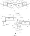
- FIG. 5is a schematic diagram of a fracturing system according to an embodiment of the present disclosure.
- the fracturing system 300includes the fracturing apparatus 100 provided by any one of the above examples.
- the fracturing system 300further includes a control system 230 ; the control system 230 includes a first control unit 231 and a first communication module 232 .
- the control system 230is electrically connected with the clutch 130 ; the control system 230 is communicatively connected with the first pressure sensor 151 , the second pressure sensor 152 , the first temperature sensor 171 , the second temperature sensor 172 , the first vibration sensor 181 , the second vibration sensor 182 , the first rotation speed sensor 191 and the second rotation speed sensor 192 .
- the control system 230can control the clutch 130 according to the parameters fed back by the first pressure sensor 151 , the second pressure sensor 152 , the first temperature sensor 171 , the second temperature sensor 172 , the first vibration sensor 181 , the second vibration sensor 182 , the first rotation speed sensor 191 and the second rotation speed sensor 192 .
- the control systemcan control the clutch to disengage so as to avoid the clutch slip phenomenon caused by the lower hydraulic pressure, thus avoiding the further deterioration of the fault and carrying out pertinent overhaul and maintenance.
- the control method of the control systemaccording to the parameters fed back by other sensors, please refer to the description of the relevant sensors, which will not be repeated here.
- control system 230can be connected with the above-mentioned sensors in a wired manner, or can be connected with the above-mentioned sensors in a wireless manner.
- the fracturing system 300further includes a remote control unit 250 .
- the remote control unit 250includes a second control module 251 , a second communication module 252 , an input module 253 and a display module 254 .
- the remote control unit 250can communicate with the first communication module 232 of the control system 230 through the second communication module 252 .
- the second control module 251is respectively connected with the input module 253 and the display module 254 . Therefore, the remote control unit 250 can receive the data of the control system 230 and display it on the display module 254 .
- the usercan also send control instructions to the control system 230 through the input module 253 of the remote control unit 250 .
- the fracturing system 300further includes a power supply unit 240 , the power supply unit 240 includes a transformer 242 .
- the power supply unit 240can be connected with the prime mover 120 to supply power to the prime mover 120 .
- the power supply unit 240can also be connected with the control system 230 to supply power to the control system 230 .
- FIG. 6is a schematic diagram of another fracturing system according to an embodiment of the present disclosure.
- the second communication module 252can be integrated in the second control module 251 , thereby improving the integration of the remote control unit. Therefore, the second control module 251 can directly receive the data of the control system 230 and display it on the display module 254 .
- the usercan also send control instructions to the control system 230 through the input module 253 of the remote control unit 250 .
- At least one embodiment of the present disclosurefurther provides a control method of a fracturing apparatus.
- the fracturing apparatuscan be the fracturing apparatus provided by any of the above examples.
- the control methodincludes: detecting the hydraulic pressure of the clutch hydraulic system; and controlling the clutch to disengage if the detected hydraulic pressure of the clutch hydraulic system is smaller than a first preset pressure value.
- the clutchUpon the hydraulic pressure value of the hydraulic oil provided to the clutch by the clutch hydraulic system being smaller than the first preset pressure value, the clutch is controlled to disengage, so that the clutch slip phenomenon caused by lower hydraulic pressure can be avoided, further deterioration of faults can be avoided, and pertinent overhaul and maintenance can be carried out.
- the hydraulic pressure of the clutch hydraulic systemcan be detected by the above-mentioned first pressure sensor, that is, the hydraulic pressure value of the hydraulic oil provided by the clutch hydraulic system to the clutch.
- control methodfurther includes: detecting the pressure of the liquid output by the plunger pump; and controlling the clutch to disengage if the detected pressure of the liquid output by the plunger pump is higher than a second preset pressure value. Therefore, if the pressure of the liquid output by the liquid output end of the plunger pump is higher than the second preset pressure value, there may be a problem with the clutch. In this case, the fracturing apparatus can control the clutch to disengage, so that the fault can be found and treated in time. It should be noted that the above-mentioned second preset pressure value can be a safe pressure value.
- the pressure of the liquid output by the plunger pumpcan be detected by the second pressure sensor described above.
- control methodfurther includes: detecting the temperature of the clutch; and controlling the clutch to disengage if the detected temperature of the clutch is higher than a first preset temperature value. Therefore, upon the temperature of the clutch being higher than the preset temperature value, the clutch can be controlled to disengage, so that various faults caused by high clutch temperature can be avoided, further deterioration of faults can be avoided, and pertinent overhaul and maintenance can be carried out.
- the temperature of the clutchcan be detected by the first temperature sensor.
- control methodfurther includes: detecting the temperature of hydraulic oil in the clutch hydraulic system; and controlling the clutch to disengage if the detected temperature of the hydraulic oil in the clutch hydraulic system is higher than a second preset temperature value. Therefore, upon the temperature of hydraulic oil in the clutch hydraulic system being higher than the second preset temperature value, the clutch can be controlled to disengage, so that various faults caused by higher clutch temperature can be avoided, further deterioration of faults can be avoided, and pertinent overhaul and maintenance can be carried out.
- the temperature of the hydraulic oil in the clutch hydraulic systemcan be detected by the second temperature sensor.
- control methodfurther includes: detecting the vibration of the plunger pump; and controlling the clutch to disengage if the detected vibration of the plunger pump is higher than a first preset vibration value.
- a first preset vibration valueDuring the operation process of fracturing apparatus, upon the clutch failing, the transmission between the clutch and the plunger pump will be abnormal, resulting in high vibration value of the plunger pump.
- the control methodcan control the clutch to disengage and completely cut off the input power of the plunger pump, thus avoiding the further deterioration of the fault and carrying out pertinent overhaul and maintenance.
- the vibration of the plunger pumpcan be detected by the first vibration sensor described above.
- control methodfurther includes: detecting vibration of the prime mover; and controlling the clutch to disengage if the detected vibration of the prime mover is higher than a second preset vibration value.
- the control methodcan control the clutch to disengage, thus avoiding the further deterioration of the fault, and carrying out pertinent overhaul and maintenance.
- control methodfurther includes: detecting a first actual rotation speed of the power input shaft of the plunger pump; detecting a second actual rotation speed of the power output shaft of the prime mover; calculating a ratio of the first actual speed and the second actual speed, and controlling the clutch to disengage if the ratio is smaller than a first preset ratio or greater than a second preset ratio. Therefore, upon the ratio of the first actual speed of the power input shaft of the plunger pump to the second actual speed of the power output shaft of the prime mover being smaller than the first preset ratio or greater than the second preset ratio (i.e., there is no match), it can be judged that the clutch is abnormal. In this case, the control method can control the clutch to disengage, so as to avoid the further deterioration of the fault, and can carry out pertinent overhaul and maintenance.
Landscapes
- Engineering & Computer Science (AREA)
- Mechanical Engineering (AREA)
- General Engineering & Computer Science (AREA)
- Life Sciences & Earth Sciences (AREA)
- Geology (AREA)
- Mining & Mineral Resources (AREA)
- Physics & Mathematics (AREA)
- Environmental & Geological Engineering (AREA)
- Fluid Mechanics (AREA)
- General Life Sciences & Earth Sciences (AREA)
- Geochemistry & Mineralogy (AREA)
- Hydraulic Clutches, Magnetic Clutches, Fluid Clutches, And Fluid Joints (AREA)
Abstract
Description
Claims (18)
Priority Applications (2)
| Application Number | Priority Date | Filing Date | Title |
|---|---|---|---|
| US18/348,761US12234712B2 (en) | 2019-09-20 | 2023-07-07 | Adaptive mobile power generation system |
| US18/659,970US20240301777A1 (en) | 2019-09-20 | 2024-05-09 | Adaptive Mobile Power Generation System |
Applications Claiming Priority (2)
| Application Number | Priority Date | Filing Date | Title |
|---|---|---|---|
| CN202110426356.1 | 2021-04-20 | ||
| CN202110426356.1ACN112983381A (en) | 2021-04-20 | 2021-04-20 | Fracturing equipment, control method thereof and fracturing system |
Related Parent Applications (1)
| Application Number | Title | Priority Date | Filing Date |
|---|---|---|---|
| US17/735,826Continuation-In-PartUS11702919B2 (en) | 2019-09-20 | 2022-05-03 | Adaptive mobile power generation system |
Related Child Applications (1)
| Application Number | Title | Priority Date | Filing Date |
|---|---|---|---|
| US18/348,761Continuation-In-PartUS12234712B2 (en) | 2019-09-20 | 2023-07-07 | Adaptive mobile power generation system |
Publications (2)
| Publication Number | Publication Date |
|---|---|
| US20220333471A1 US20220333471A1 (en) | 2022-10-20 |
| US12320344B2true US12320344B2 (en) | 2025-06-03 |
Family
ID=76341358
Family Applications (1)
| Application Number | Title | Priority Date | Filing Date |
|---|---|---|---|
| US17/493,573Active2042-08-28US12320344B2 (en) | 2019-09-20 | 2021-10-04 | Fracturing apparatus and control method thereof, fracturing system |
Country Status (3)
| Country | Link |
|---|---|
| US (1) | US12320344B2 (en) |
| CN (1) | CN112983381A (en) |
| WO (1) | WO2022222518A1 (en) |
Families Citing this family (46)
| Publication number | Priority date | Publication date | Assignee | Title |
|---|---|---|---|---|
| US11624326B2 (en) | 2017-05-21 | 2023-04-11 | Bj Energy Solutions, Llc | Methods and systems for supplying fuel to gas turbine engines |
| US11560845B2 (en) | 2019-05-15 | 2023-01-24 | Bj Energy Solutions, Llc | Mobile gas turbine inlet air conditioning system and associated methods |
| US11680474B2 (en) | 2019-06-13 | 2023-06-20 | Yantai Jereh Petroleum Equipment & Technologies Co., Ltd. | Fracturing apparatus and control method thereof, fracturing system |
| US11746636B2 (en) | 2019-10-30 | 2023-09-05 | Yantai Jereh Petroleum Equipment & Technologies Co., Ltd. | Fracturing apparatus and control method thereof, fracturing system |
| US12326074B2 (en) | 2019-06-13 | 2025-06-10 | Yantai Jereh Petroleum Equipment & Technologies Co., Ltd. | Fracturing apparatus and control method thereof, fracturing system |
| US12173594B2 (en) | 2019-06-13 | 2024-12-24 | Yantai Jereh Petroleum Equipment & Technologies Co., Ltd. | Fracturing system |
| CN112983381A (en) | 2021-04-20 | 2021-06-18 | 烟台杰瑞石油装备技术有限公司 | Fracturing equipment, control method thereof and fracturing system |
| US11604113B2 (en) | 2019-09-13 | 2023-03-14 | Bj Energy Solutions, Llc | Fuel, communications, and power connection systems and related methods |
| US10895202B1 (en) | 2019-09-13 | 2021-01-19 | Bj Energy Solutions, Llc | Direct drive unit removal system and associated methods |
| CA3197583A1 (en) | 2019-09-13 | 2021-03-13 | Bj Energy Solutions, Llc | Fuel, communications, and power connection systems and related methods |
| US10961914B1 (en) | 2019-09-13 | 2021-03-30 | BJ Energy Solutions, LLC Houston | Turbine engine exhaust duct system and methods for noise dampening and attenuation |
| CA3092829C (en) | 2019-09-13 | 2023-08-15 | Bj Energy Solutions, Llc | Methods and systems for supplying fuel to gas turbine engines |
| US10815764B1 (en) | 2019-09-13 | 2020-10-27 | Bj Energy Solutions, Llc | Methods and systems for operating a fleet of pumps |
| CA3092865C (en) | 2019-09-13 | 2023-07-04 | Bj Energy Solutions, Llc | Power sources and transmission networks for auxiliary equipment onboard hydraulic fracturing units and associated methods |
| US12338772B2 (en) | 2019-09-13 | 2025-06-24 | Bj Energy Solutions, Llc | Systems, assemblies, and methods to enhance intake air flow to a gas turbine engine of a hydraulic fracturing unit |
| US12065968B2 (en) | 2019-09-13 | 2024-08-20 | BJ Energy Solutions, Inc. | Systems and methods for hydraulic fracturing |
| US11002189B2 (en) | 2019-09-13 | 2021-05-11 | Bj Energy Solutions, Llc | Mobile gas turbine inlet air conditioning system and associated methods |
| CA3092863C (en) | 2019-09-13 | 2023-07-18 | Bj Energy Solutions, Llc | Fuel, communications, and power connection systems and related methods |
| US11015594B2 (en) | 2019-09-13 | 2021-05-25 | Bj Energy Solutions, Llc | Systems and method for use of single mass flywheel alongside torsional vibration damper assembly for single acting reciprocating pump |
| US12234712B2 (en) | 2019-09-20 | 2025-02-25 | Yantai Jereh Petroleum Equipment & Technologies Co., Ltd. | Adaptive mobile power generation system |
| US11708829B2 (en) | 2020-05-12 | 2023-07-25 | Bj Energy Solutions, Llc | Cover for fluid systems and related methods |
| US10968837B1 (en) | 2020-05-14 | 2021-04-06 | Bj Energy Solutions, Llc | Systems and methods utilizing turbine compressor discharge for hydrostatic manifold purge |
| US11428165B2 (en) | 2020-05-15 | 2022-08-30 | Bj Energy Solutions, Llc | Onboard heater of auxiliary systems using exhaust gases and associated methods |
| US11208880B2 (en) | 2020-05-28 | 2021-12-28 | Bj Energy Solutions, Llc | Bi-fuel reciprocating engine to power direct drive turbine fracturing pumps onboard auxiliary systems and related methods |
| US11208953B1 (en) | 2020-06-05 | 2021-12-28 | Bj Energy Solutions, Llc | Systems and methods to enhance intake air flow to a gas turbine engine of a hydraulic fracturing unit |
| US11109508B1 (en) | 2020-06-05 | 2021-08-31 | Bj Energy Solutions, Llc | Enclosure assembly for enhanced cooling of direct drive unit and related methods |
| US10954770B1 (en) | 2020-06-09 | 2021-03-23 | Bj Energy Solutions, Llc | Systems and methods for exchanging fracturing components of a hydraulic fracturing unit |
| US11066915B1 (en) | 2020-06-09 | 2021-07-20 | Bj Energy Solutions, Llc | Methods for detection and mitigation of well screen out |
| US11111768B1 (en) | 2020-06-09 | 2021-09-07 | Bj Energy Solutions, Llc | Drive equipment and methods for mobile fracturing transportation platforms |
| US11939853B2 (en) | 2020-06-22 | 2024-03-26 | Bj Energy Solutions, Llc | Systems and methods providing a configurable staged rate increase function to operate hydraulic fracturing units |
| US11028677B1 (en) | 2020-06-22 | 2021-06-08 | Bj Energy Solutions, Llc | Stage profiles for operations of hydraulic systems and associated methods |
| US11933153B2 (en) | 2020-06-22 | 2024-03-19 | Bj Energy Solutions, Llc | Systems and methods to operate hydraulic fracturing units using automatic flow rate and/or pressure control |
| US11125066B1 (en) | 2020-06-22 | 2021-09-21 | Bj Energy Solutions, Llc | Systems and methods to operate a dual-shaft gas turbine engine for hydraulic fracturing |
| US11466680B2 (en) | 2020-06-23 | 2022-10-11 | Bj Energy Solutions, Llc | Systems and methods of utilization of a hydraulic fracturing unit profile to operate hydraulic fracturing units |
| US11473413B2 (en) | 2020-06-23 | 2022-10-18 | Bj Energy Solutions, Llc | Systems and methods to autonomously operate hydraulic fracturing units |
| US11149533B1 (en) | 2020-06-24 | 2021-10-19 | Bj Energy Solutions, Llc | Systems to monitor, detect, and/or intervene relative to cavitation and pulsation events during a hydraulic fracturing operation |
| US11220895B1 (en) | 2020-06-24 | 2022-01-11 | Bj Energy Solutions, Llc | Automated diagnostics of electronic instrumentation in a system for fracturing a well and associated methods |
| US11193360B1 (en) | 2020-07-17 | 2021-12-07 | Bj Energy Solutions, Llc | Methods, systems, and devices to enhance fracturing fluid delivery to subsurface formations during high-pressure fracturing operations |
| US11639654B2 (en) | 2021-05-24 | 2023-05-02 | Bj Energy Solutions, Llc | Hydraulic fracturing pumps to enhance flow of fracturing fluid into wellheads and related methods |
| CN113446209B (en)* | 2021-08-12 | 2025-05-09 | 烟台杰瑞石油装备技术有限公司 | Fracturing equipment and vibration reduction method thereof |
| WO2023015687A1 (en) | 2021-08-12 | 2023-02-16 | 烟台杰瑞石油装备技术有限公司 | Fracturing apparatus and vibration reduction method thereof |
| CA3180024A1 (en) | 2021-10-25 | 2023-04-25 | Bj Energy Solutions, Llc | Systems and methods to reduce acoustic resonance or disrupt standing wave formation in a fluid manifold of a high-pressure fracturing system |
| CN114576129A (en)* | 2022-02-17 | 2022-06-03 | 烟台杰瑞石油装备技术有限公司 | Fracturing device |
| US20240026876A1 (en)* | 2022-07-19 | 2024-01-25 | Caterpillar Inc. | Control of a dual-pump single-power source system |
| US12203459B2 (en)* | 2022-07-19 | 2025-01-21 | Caterpillar Inc. | Control of a dual-pump single-power source system |
| CN116446833A (en)* | 2023-01-09 | 2023-07-18 | 烟台杰瑞石油装备技术有限公司 | Electric drive fracturing equipment and braking method thereof |
Citations (75)
| Publication number | Priority date | Publication date | Assignee | Title |
|---|---|---|---|---|
| US3794377A (en)* | 1972-06-05 | 1974-02-26 | E Wachsmuth | Compressor enclosure |
| US3815965A (en)* | 1972-10-10 | 1974-06-11 | Smith & Co Inc Gordon | Air compressor housings |
| US4201523A (en)* | 1978-01-23 | 1980-05-06 | Olofsson Bjorn O E | Device for cooling and silencing of noise of a compressor or vacuum pump |
| US4793775A (en)* | 1984-10-13 | 1988-12-27 | Aspera S.R.L. | Hermetic motor-compressor unit for refrigeration circuits |
| US5282722A (en) | 1991-06-12 | 1994-02-01 | Wagner Spray Tech Corporation | Electronic pressure control |
| US5846056A (en)* | 1995-04-07 | 1998-12-08 | Dhindsa; Jasbir S. | Reciprocating pump system and method for operating same |
| US6134878A (en)* | 1997-09-24 | 2000-10-24 | Sts Corporation | Cooling arrangement for a gas turbine driven power system |
| US20030064858A1 (en)* | 2001-09-10 | 2003-04-03 | Nissan Motor Co., Ltd. | Vehicle with clutch for transmission of torque output of motor |
| US20050093496A1 (en)* | 2003-10-29 | 2005-05-05 | Nissan Motor Co., Ltd. | Vehicle drive force control apparatus |
| US7036310B2 (en) | 2003-10-15 | 2006-05-02 | Honda Motor Co., Ltd. | Hydraulic controller for hydraulic actuator |
| CN201461291U (en) | 2009-07-27 | 2010-05-12 | 河南省煤层气开发利用有限公司 | Underground fracturing plunger pump unit in coal mine |
| US20100135840A1 (en)* | 2008-11-28 | 2010-06-03 | Hitachi Industrial Equipment Systems Co., Ltd. | Screw compressor |
| US20110061411A1 (en) | 2008-02-20 | 2011-03-17 | Jong-Kwon Kim | Linear Compressor |
| CN201953368U (en) | 2011-03-07 | 2011-08-31 | 杜劼 | Coal mine underground unitized fracturing device |
| CN202544830U (en) | 2012-04-20 | 2012-11-21 | 河南易安能源科技有限公司 | Fracturing blender truck for oil field or coal bed gas mining |
| CN202645914U (en) | 2012-04-01 | 2013-01-02 | 河南易安能源科技有限公司 | Fracturing plunger pump set |
| US8459958B2 (en)* | 2009-09-03 | 2013-06-11 | Illinois Tool Works, Inc. | Automatic compressor overpressure control |
| US20130255153A1 (en) | 2012-03-30 | 2013-10-03 | Hitachi, Ltd. | Method of Gas Purification, Coal Gasification Plant, and Shift Catalyst |
| US8731793B2 (en)* | 2010-12-29 | 2014-05-20 | Caterpillar Inc. | Clutch temperature estimation for a mobile machine |
| US8788161B2 (en)* | 2010-11-25 | 2014-07-22 | Voith Patent Gmbh | Method for setting the working pressure of a transmission |
| US20140219824A1 (en)* | 2013-02-06 | 2014-08-07 | Baker Hughes Incorporated | Pump system and method thereof |
| US20160041066A1 (en)* | 2015-10-23 | 2016-02-11 | Caterpillar Inc. | Method for monitoring temperature of clutch assembly |
| US20160121871A1 (en) | 2014-10-31 | 2016-05-05 | Hyundai Motor Company | System and method for controlling vacuum pump in gasoline vehicle with clutch |
| RU163399U1 (en) | 2015-07-01 | 2016-07-20 | Публичное акционерное общество "Татнефть" им. В.Д. Шашина | VIBRATION REDUCED PUMP PUMP UNIT |
| CN205479153U (en) | 2016-01-28 | 2016-08-17 | 烟台杰瑞石油装备技术有限公司 | Be applied to deceleration drive device among fracturing, solid well equipment |
| US20170285062A1 (en)* | 2016-03-29 | 2017-10-05 | Hyundai Motor Company | Electric oil pump control method for operating transmission of hybrid vehicle |
| CN107237617A (en) | 2017-07-27 | 2017-10-10 | 中石化石油工程机械有限公司第四机械厂 | A kind of electricity of single-machine double-pump structure drives pressure break equipment |
| US20170292789A1 (en) | 2016-04-10 | 2017-10-12 | Global Heat Transfer Ulc | Heat exchanger unit |
| WO2018025891A1 (en) | 2016-08-05 | 2018-02-08 | 日本電産トーソク株式会社 | Clutch control device |
| CN107816341A (en) | 2017-10-26 | 2018-03-20 | 宝鸡石油机械有限责任公司 | A kind of hydraulic-driven Modular pump pressure break sledge |
| RU178973U1 (en) | 2018-01-09 | 2018-04-24 | Владимир Алексеевич Попов | INSTALLATION PUMP UNIVERSAL |
| CN108443099A (en) | 2018-04-28 | 2018-08-24 | 中国石油天然气集团有限公司 | A kind of compound gearing for pressure break plunger pump |
| US20180328157A1 (en)* | 2017-05-11 | 2018-11-15 | Mgb Oilfield Solutions, L.L.C. | Equipment, system and method for delivery of high pressure fluid |
| US20180335096A1 (en) | 2017-05-22 | 2018-11-22 | Hyundai Motor Company | System and method for controlling engine clutch |
| CN208281489U (en) | 2018-04-27 | 2018-12-25 | 徐州重型机械有限公司 | A kind of detection hydraulic clutch and its vehicle |
| CN109296733A (en) | 2018-09-27 | 2019-02-01 | 湖北航天技术研究院总体设计所 | A kind of automotive transfer case fault monitoring system and method |
| US10240643B2 (en) | 2014-12-11 | 2019-03-26 | PT Tech, LLC | Self-contained clutch for diesel engines |
| US20190100989A1 (en)* | 2017-10-02 | 2019-04-04 | S.P.M. Flow Control, Inc. | System and Method for Universal Fracturing Site Equipment Monitoring |
| CN109578459A (en) | 2018-12-25 | 2019-04-05 | 中石化四机石油机械有限公司 | Clutch and control method for fracturing device |
| US20190128265A1 (en)* | 2017-11-02 | 2019-05-02 | Kabushiki Kaisha Kobe Seiko Sho (Kobe Steel, Ltd.) | Gas supplying apparatus |
| US20190169971A1 (en) | 2017-12-05 | 2019-06-06 | U.S. Well Services, Inc. | High horsepower pumping configuration for an electric hydraulic fracturing system |
| US20190195292A1 (en)* | 2017-12-22 | 2019-06-27 | Caterpillar Inc. | Clutch Local Peak Temperature Real Time Predictor and Applications |
| CN209041375U (en) | 2018-10-09 | 2019-06-28 | 伟攀(上海)机械设备有限公司 | A kind of radial extensible structure of fracturing pump hydraulic clutch |
| CN209469732U (en) | 2018-12-25 | 2019-10-08 | 中石化四机石油机械有限公司 | Clutch for fracturing device |
| CN110374164A (en) | 2019-07-25 | 2019-10-25 | 徐州徐工矿业机械有限公司 | A kind of hydraulic crawler excavator dynamical system Fault monitoring and diagnosis system and method |
| US20200040878A1 (en)* | 2018-08-06 | 2020-02-06 | Typhon Technology Solutions, Llc | Engagement and disengagement with external gear box style pumps |
| US20200049136A1 (en)* | 2016-11-29 | 2020-02-13 | Halliburton Energy Services, Inc. | Dual turbine direct drive pump |
| US20200109616A1 (en) | 2018-10-09 | 2020-04-09 | U.S. Well Services, LLC | Electric Powered Hydraulic Fracturing Pump System with Single Electric Powered Multi-Plunger Pump Fracturing Trailers, Filtration Units, and Slide Out Platform |
| US20200109617A1 (en) | 2018-10-09 | 2020-04-09 | U.S. Well Services, LLC | Modular switchgear system and power distribution for electric oilfield equipment |
| CN111043023A (en) | 2019-12-27 | 2020-04-21 | 橙色云设计有限公司 | A fracturing pump online monitoring and fault diagnosis system |
| CN111156266A (en) | 2020-03-05 | 2020-05-15 | 伟攀(上海)机械设备有限公司 | Hydraulic clutch of fracturing pump with double rotary joints |
| CN111502974A (en) | 2020-05-28 | 2020-08-07 | 美国杰瑞国际有限公司 | Plunger pump state monitoring and fault diagnosis system |
| US20200325760A1 (en)* | 2019-04-12 | 2020-10-15 | The Modern Group, Ltd. | Hydraulic fracturing pump system |
| US10865624B1 (en) | 2019-09-24 | 2020-12-15 | Yantai Jereh Petroleum Equipment & Technologies Co., Ltd. | Wellsite system for electric drive fracturing |
| US20210040836A1 (en) | 2019-08-07 | 2021-02-11 | CS&P Technologies LP | Lubrication system for a plunger/packing set of a fluid end |
| US20210040830A1 (en)* | 2018-01-23 | 2021-02-11 | Schlumberger Technology Corporation | Automated Control of Hydraulic Fracturing Pumps |
| US20210079902A1 (en) | 2019-09-13 | 2021-03-18 | Bj Services, Llc | Power sources and transmission networks for auxiliary equipment onboard hydraulic fracturing units and associated methods |
| US20210095648A1 (en)* | 2019-10-01 | 2021-04-01 | St9 Gas And Oil, Llc | Electric drive pump for well stimulation |
| US20210102451A1 (en) | 2019-10-03 | 2021-04-08 | U.S. Well Services, LLC | Electric powered hydraulic fracturing pump system with single electric powered multi-plunger fracturing pump |
| US20210102530A1 (en)* | 2018-05-01 | 2021-04-08 | Cameron International Corporation | Fluid pumping using electric linear motor |
| CN112983381A (en) | 2021-04-20 | 2021-06-18 | 烟台杰瑞石油装备技术有限公司 | Fracturing equipment, control method thereof and fracturing system |
| US20210207588A1 (en) | 2019-09-13 | 2021-07-08 | Bj Energy Solutions, Llc | Power sources and transmission networks for auxiliary equipment onboard hydraulic fracturing units and associated methods |
| US11109508B1 (en)* | 2020-06-05 | 2021-08-31 | Bj Energy Solutions, Llc | Enclosure assembly for enhanced cooling of direct drive unit and related methods |
| US11125066B1 (en)* | 2020-06-22 | 2021-09-21 | Bj Energy Solutions, Llc | Systems and methods to operate a dual-shaft gas turbine engine for hydraulic fracturing |
| US20210310341A1 (en) | 2018-05-01 | 2021-10-07 | David Sherman | Powertrain for wellsite operations and method |
| US11162484B2 (en)* | 2012-08-30 | 2021-11-02 | Illinois Tool Works Inc. | Service pack comprising an engine driving a pneumatic air compression system with a flow control system to adjust a position of a proportional control valve, regulate a variable pressure acting on a flow control member, and regulate a power demand placed on the engine |
| CN214741267U (en) | 2021-04-20 | 2021-11-16 | 烟台杰瑞石油装备技术有限公司 | Fracturing device and fracturing system |
| US20210355802A1 (en) | 2019-09-13 | 2021-11-18 | Bj Energy Solutions, Llc | Methods and systems for operating a fleet of pumps |
| US11220895B1 (en)* | 2020-06-24 | 2022-01-11 | Bj Energy Solutions, Llc | Automated diagnostics of electronic instrumentation in a system for fracturing a well and associated methods |
| US20220112892A1 (en) | 2019-10-30 | 2022-04-14 | Yantai Jereh Petroleum Equipment & Technologies Co., Ltd. | Variable-speed integrated machine and wellsite apparatus |
| US11378008B2 (en)* | 2020-06-05 | 2022-07-05 | Bj Energy Solutions, Llc | Systems and methods to enhance intake air flow to a gas turbine engine of a hydraulic fracturing unit |
| US20220213777A1 (en) | 2019-09-24 | 2022-07-07 | Yantai Jereh Petroleum Equipment & Technologies Co., Ltd. | Electrically-driven fracturing well site system |
| US11391136B2 (en)* | 2011-04-07 | 2022-07-19 | Typhon Technology Solutions (U.S.), Llc | Dual pump VFD controlled motor electric fracturing system |
| US20220298906A1 (en) | 2019-10-30 | 2022-09-22 | Yantai Jereh Petroleum Equipment & Technologies Co., Ltd. | Fracturing apparatus and control method thereof, fracturing system |
| US20230296050A1 (en) | 2019-09-13 | 2023-09-21 | Bj Energy Solutions, Llc | Systems and methods for hydraulic fracturing |
- 2021
- 2021-04-20CNCN202110426356.1Apatent/CN112983381A/enactivePending
- 2021-10-04USUS17/493,573patent/US12320344B2/enactiveActive
- 2021-12-17WOPCT/CN2021/139240patent/WO2022222518A1/ennot_activeCeased
Patent Citations (106)
| Publication number | Priority date | Publication date | Assignee | Title |
|---|---|---|---|---|
| US3794377A (en)* | 1972-06-05 | 1974-02-26 | E Wachsmuth | Compressor enclosure |
| US3815965A (en)* | 1972-10-10 | 1974-06-11 | Smith & Co Inc Gordon | Air compressor housings |
| US4201523A (en)* | 1978-01-23 | 1980-05-06 | Olofsson Bjorn O E | Device for cooling and silencing of noise of a compressor or vacuum pump |
| US4793775A (en)* | 1984-10-13 | 1988-12-27 | Aspera S.R.L. | Hermetic motor-compressor unit for refrigeration circuits |
| US5282722A (en) | 1991-06-12 | 1994-02-01 | Wagner Spray Tech Corporation | Electronic pressure control |
| US5846056A (en)* | 1995-04-07 | 1998-12-08 | Dhindsa; Jasbir S. | Reciprocating pump system and method for operating same |
| US6134878A (en)* | 1997-09-24 | 2000-10-24 | Sts Corporation | Cooling arrangement for a gas turbine driven power system |
| US20030064858A1 (en)* | 2001-09-10 | 2003-04-03 | Nissan Motor Co., Ltd. | Vehicle with clutch for transmission of torque output of motor |
| US7036310B2 (en) | 2003-10-15 | 2006-05-02 | Honda Motor Co., Ltd. | Hydraulic controller for hydraulic actuator |
| US20050093496A1 (en)* | 2003-10-29 | 2005-05-05 | Nissan Motor Co., Ltd. | Vehicle drive force control apparatus |
| US20110061411A1 (en) | 2008-02-20 | 2011-03-17 | Jong-Kwon Kim | Linear Compressor |
| US20100135840A1 (en)* | 2008-11-28 | 2010-06-03 | Hitachi Industrial Equipment Systems Co., Ltd. | Screw compressor |
| CN201461291U (en) | 2009-07-27 | 2010-05-12 | 河南省煤层气开发利用有限公司 | Underground fracturing plunger pump unit in coal mine |
| US8459958B2 (en)* | 2009-09-03 | 2013-06-11 | Illinois Tool Works, Inc. | Automatic compressor overpressure control |
| US8788161B2 (en)* | 2010-11-25 | 2014-07-22 | Voith Patent Gmbh | Method for setting the working pressure of a transmission |
| US8731793B2 (en)* | 2010-12-29 | 2014-05-20 | Caterpillar Inc. | Clutch temperature estimation for a mobile machine |
| CN201953368U (en) | 2011-03-07 | 2011-08-31 | 杜劼 | Coal mine underground unitized fracturing device |
| US11391136B2 (en)* | 2011-04-07 | 2022-07-19 | Typhon Technology Solutions (U.S.), Llc | Dual pump VFD controlled motor electric fracturing system |
| US20130255153A1 (en) | 2012-03-30 | 2013-10-03 | Hitachi, Ltd. | Method of Gas Purification, Coal Gasification Plant, and Shift Catalyst |
| CN202645914U (en) | 2012-04-01 | 2013-01-02 | 河南易安能源科技有限公司 | Fracturing plunger pump set |
| CN202544830U (en) | 2012-04-20 | 2012-11-21 | 河南易安能源科技有限公司 | Fracturing blender truck for oil field or coal bed gas mining |
| US11162484B2 (en)* | 2012-08-30 | 2021-11-02 | Illinois Tool Works Inc. | Service pack comprising an engine driving a pneumatic air compression system with a flow control system to adjust a position of a proportional control valve, regulate a variable pressure acting on a flow control member, and regulate a power demand placed on the engine |
| US20140219824A1 (en)* | 2013-02-06 | 2014-08-07 | Baker Hughes Incorporated | Pump system and method thereof |
| US20160121871A1 (en) | 2014-10-31 | 2016-05-05 | Hyundai Motor Company | System and method for controlling vacuum pump in gasoline vehicle with clutch |
| CN106143468A (en) | 2014-10-31 | 2016-11-23 | 现代自动车株式会社 | For controlling the System and method for the vacuum pump in the gasoline vehicle of clutch |
| US10240643B2 (en) | 2014-12-11 | 2019-03-26 | PT Tech, LLC | Self-contained clutch for diesel engines |
| RU163399U1 (en) | 2015-07-01 | 2016-07-20 | Публичное акционерное общество "Татнефть" им. В.Д. Шашина | VIBRATION REDUCED PUMP PUMP UNIT |
| US20160041066A1 (en)* | 2015-10-23 | 2016-02-11 | Caterpillar Inc. | Method for monitoring temperature of clutch assembly |
| CN205479153U (en) | 2016-01-28 | 2016-08-17 | 烟台杰瑞石油装备技术有限公司 | Be applied to deceleration drive device among fracturing, solid well equipment |
| US20170285062A1 (en)* | 2016-03-29 | 2017-10-05 | Hyundai Motor Company | Electric oil pump control method for operating transmission of hybrid vehicle |
| US20170292789A1 (en) | 2016-04-10 | 2017-10-12 | Global Heat Transfer Ulc | Heat exchanger unit |
| WO2018025891A1 (en) | 2016-08-05 | 2018-02-08 | 日本電産トーソク株式会社 | Clutch control device |
| US20210199161A1 (en)* | 2016-08-05 | 2021-07-01 | Nidec Tosok Corporation | Clutch control device |
| US20200049136A1 (en)* | 2016-11-29 | 2020-02-13 | Halliburton Energy Services, Inc. | Dual turbine direct drive pump |
| US20180328157A1 (en)* | 2017-05-11 | 2018-11-15 | Mgb Oilfield Solutions, L.L.C. | Equipment, system and method for delivery of high pressure fluid |
| US20180335096A1 (en) | 2017-05-22 | 2018-11-22 | Hyundai Motor Company | System and method for controlling engine clutch |
| CN107237617A (en) | 2017-07-27 | 2017-10-10 | 中石化石油工程机械有限公司第四机械厂 | A kind of electricity of single-machine double-pump structure drives pressure break equipment |
| US20190100989A1 (en)* | 2017-10-02 | 2019-04-04 | S.P.M. Flow Control, Inc. | System and Method for Universal Fracturing Site Equipment Monitoring |
| CN107816341A (en) | 2017-10-26 | 2018-03-20 | 宝鸡石油机械有限责任公司 | A kind of hydraulic-driven Modular pump pressure break sledge |
| US20190128265A1 (en)* | 2017-11-02 | 2019-05-02 | Kabushiki Kaisha Kobe Seiko Sho (Kobe Steel, Ltd.) | Gas supplying apparatus |
| US20190169971A1 (en) | 2017-12-05 | 2019-06-06 | U.S. Well Services, Inc. | High horsepower pumping configuration for an electric hydraulic fracturing system |
| US11434737B2 (en) | 2017-12-05 | 2022-09-06 | U.S. Well Services, LLC | High horsepower pumping configuration for an electric hydraulic fracturing system |
| US20210095552A1 (en) | 2017-12-05 | 2021-04-01 | U.S. Well Services, LLC | High horsepower pumping configuration for an electric hydraulic fracturing system |
| US10648311B2 (en) | 2017-12-05 | 2020-05-12 | U.S. Well Services, LLC | High horsepower pumping configuration for an electric hydraulic fracturing system |
| US20190195292A1 (en)* | 2017-12-22 | 2019-06-27 | Caterpillar Inc. | Clutch Local Peak Temperature Real Time Predictor and Applications |
| RU178973U1 (en) | 2018-01-09 | 2018-04-24 | Владимир Алексеевич Попов | INSTALLATION PUMP UNIVERSAL |
| US20210040830A1 (en)* | 2018-01-23 | 2021-02-11 | Schlumberger Technology Corporation | Automated Control of Hydraulic Fracturing Pumps |
| CN208281489U (en) | 2018-04-27 | 2018-12-25 | 徐州重型机械有限公司 | A kind of detection hydraulic clutch and its vehicle |
| CN108443099A (en) | 2018-04-28 | 2018-08-24 | 中国石油天然气集团有限公司 | A kind of compound gearing for pressure break plunger pump |
| US20210310341A1 (en) | 2018-05-01 | 2021-10-07 | David Sherman | Powertrain for wellsite operations and method |
| US20210102530A1 (en)* | 2018-05-01 | 2021-04-08 | Cameron International Corporation | Fluid pumping using electric linear motor |
| US20200040878A1 (en)* | 2018-08-06 | 2020-02-06 | Typhon Technology Solutions, Llc | Engagement and disengagement with external gear box style pumps |
| CN109296733A (en) | 2018-09-27 | 2019-02-01 | 湖北航天技术研究院总体设计所 | A kind of automotive transfer case fault monitoring system and method |
| US11578580B2 (en) | 2018-10-09 | 2023-02-14 | U.S. Well Services, LLC | Electric powered hydraulic fracturing pump system with single electric powered multi-plunger pump fracturing trailers, filtration units, and slide out platform |
| US20220364448A1 (en) | 2018-10-09 | 2022-11-17 | U.S. Well Services, LLC | Modular switchgear system and power distribution for electric oilfield equipment |
| US20220018232A1 (en) | 2018-10-09 | 2022-01-20 | U.S. Well Services, LLC | Electric Powered Hydraulic Fracturing Pump System with Single Electric Powered Multi-Plunger Pump Fracturing Trailers, Filtration Units, and Slide Out Platform |
| US11208878B2 (en) | 2018-10-09 | 2021-12-28 | U.S. Well Services, LLC | Modular switchgear system and power distribution for electric oilfield equipment |
| US10914155B2 (en) | 2018-10-09 | 2021-02-09 | U.S. Well Services, LLC | Electric powered hydraulic fracturing pump system with single electric powered multi-plunger pump fracturing trailers, filtration units, and slide out platform |
| US20200109617A1 (en) | 2018-10-09 | 2020-04-09 | U.S. Well Services, LLC | Modular switchgear system and power distribution for electric oilfield equipment |
| US20200109616A1 (en) | 2018-10-09 | 2020-04-09 | U.S. Well Services, LLC | Electric Powered Hydraulic Fracturing Pump System with Single Electric Powered Multi-Plunger Pump Fracturing Trailers, Filtration Units, and Slide Out Platform |
| US12116875B2 (en) | 2018-10-09 | 2024-10-15 | U.S. Well Services, LLC | Electric powered hydraulic fracturing pump system with single electric powered multi-plunger pump fracturing trailers, filtration units, and slide out platform |
| US20230272699A1 (en) | 2018-10-09 | 2023-08-31 | U.S. Well Services, LLC | Electric Powered Hydraulic Fracturing Pump System with Single Electric Powered Multi-Plunger Pump Fracturing Trailers, Filtration Units, and Slide Out Platform |
| CN209041375U (en) | 2018-10-09 | 2019-06-28 | 伟攀(上海)机械设备有限公司 | A kind of radial extensible structure of fracturing pump hydraulic clutch |
| CN109578459B (en) | 2018-12-25 | 2020-07-07 | 中石化四机石油机械有限公司 | Clutch for fracturing device and control method |
| CN209469732U (en) | 2018-12-25 | 2019-10-08 | 中石化四机石油机械有限公司 | Clutch for fracturing device |
| CN109578459A (en) | 2018-12-25 | 2019-04-05 | 中石化四机石油机械有限公司 | Clutch and control method for fracturing device |
| US20200325760A1 (en)* | 2019-04-12 | 2020-10-15 | The Modern Group, Ltd. | Hydraulic fracturing pump system |
| CN110374164A (en) | 2019-07-25 | 2019-10-25 | 徐州徐工矿业机械有限公司 | A kind of hydraulic crawler excavator dynamical system Fault monitoring and diagnosis system and method |
| US20210040836A1 (en) | 2019-08-07 | 2021-02-11 | CS&P Technologies LP | Lubrication system for a plunger/packing set of a fluid end |
| US11859482B2 (en) | 2019-09-13 | 2024-01-02 | Bj Energy Solutions, Llc | Power sources and transmission networks for auxiliary equipment onboard hydraulic fracturing units and associated methods |
| US10989180B2 (en) | 2019-09-13 | 2021-04-27 | Bj Energy Solutions, Llc | Power sources and transmission networks for auxiliary equipment onboard hydraulic fracturing units and associated methods |
| US20240295191A1 (en) | 2019-09-13 | 2024-09-05 | Bj Energy Solutions, Llc | Systems and methods for hydraulic fracturing |
| US20210079902A1 (en) | 2019-09-13 | 2021-03-18 | Bj Services, Llc | Power sources and transmission networks for auxiliary equipment onboard hydraulic fracturing units and associated methods |
| US20210207588A1 (en) | 2019-09-13 | 2021-07-08 | Bj Energy Solutions, Llc | Power sources and transmission networks for auxiliary equipment onboard hydraulic fracturing units and associated methods |
| US12065968B2 (en) | 2019-09-13 | 2024-08-20 | BJ Energy Solutions, Inc. | Systems and methods for hydraulic fracturing |
| US20210355802A1 (en) | 2019-09-13 | 2021-11-18 | Bj Energy Solutions, Llc | Methods and systems for operating a fleet of pumps |
| US20230296050A1 (en) | 2019-09-13 | 2023-09-21 | Bj Energy Solutions, Llc | Systems and methods for hydraulic fracturing |
| US20240093583A1 (en) | 2019-09-13 | 2024-03-21 | Bj Energy Solutions, Llc | Power sources and transmission networks for auxiliary equipment onboard hydraulic fracturing units and associated methods |
| US20230203927A1 (en) | 2019-09-13 | 2023-06-29 | Bj Energy Solutions, Llc | Power sources and transmission networks for auxiliary equipment onboard hydraulic fracturing units and associated methods |
| US11236739B2 (en) | 2019-09-13 | 2022-02-01 | Bj Energy Solutions, Llc | Power sources and transmission networks for auxiliary equipment onboard hydraulic fracturing units and associated methods |
| US11629584B2 (en) | 2019-09-13 | 2023-04-18 | Bj Energy Solutions, Llc | Power sources and transmission networks for auxiliary equipment onboard hydraulic fracturing units and associated methods |
| US20220112889A1 (en) | 2019-09-13 | 2022-04-14 | Bj Energy Solutions, Llc | Power sources and transmission networks for auxiliary equipment onboard hydraulic fracturing units and associated methods |
| US20230055844A1 (en) | 2019-09-13 | 2023-02-23 | Bj Energy Solutions, Llc | Power sources and transmission networks for auxiliary equipment onboard hydraulic fracturing units and associated methods |
| US11530602B2 (en) | 2019-09-13 | 2022-12-20 | Bj Energy Solutions, Llc | Power sources and transmission networks for auxiliary equipment onboard hydraulic fracturing units and associated methods |
| US10865624B1 (en) | 2019-09-24 | 2020-12-15 | Yantai Jereh Petroleum Equipment & Technologies Co., Ltd. | Wellsite system for electric drive fracturing |
| US20220213777A1 (en) | 2019-09-24 | 2022-07-07 | Yantai Jereh Petroleum Equipment & Technologies Co., Ltd. | Electrically-driven fracturing well site system |
| US20210095648A1 (en)* | 2019-10-01 | 2021-04-01 | St9 Gas And Oil, Llc | Electric drive pump for well stimulation |
| US11459863B2 (en) | 2019-10-03 | 2022-10-04 | U.S. Well Services, LLC | Electric powered hydraulic fracturing pump system with single electric powered multi-plunger fracturing pump |
| US20210102451A1 (en) | 2019-10-03 | 2021-04-08 | U.S. Well Services, LLC | Electric powered hydraulic fracturing pump system with single electric powered multi-plunger fracturing pump |
| US20240392666A1 (en) | 2019-10-03 | 2024-11-28 | U.S. Well Services, LLC | Electric Powered Hydraulic Fracturing Pump System with Single Electric Powered Multi-Plunger Fracturing Pump |
| US20240084680A1 (en) | 2019-10-03 | 2024-03-14 | U.S. Well Services, LLC | Electric Powered Hydraulic Fracturing Pump System with Single Electric Powered Multi-Plunger Fracturing Pump |
| US20230146951A1 (en) | 2019-10-03 | 2023-05-11 | U.S. Well Services, LLC | Electric powered hydraulic fracturing pump system with single electric powered multi-plunger fracturing pump |
| US12084952B2 (en) | 2019-10-03 | 2024-09-10 | U.S. Well Services, LLC | Electric powered hydraulic fracturing pump system with single electric powered multi-plunger fracturing pump |
| US20220298906A1 (en) | 2019-10-30 | 2022-09-22 | Yantai Jereh Petroleum Equipment & Technologies Co., Ltd. | Fracturing apparatus and control method thereof, fracturing system |
| US20220112892A1 (en) | 2019-10-30 | 2022-04-14 | Yantai Jereh Petroleum Equipment & Technologies Co., Ltd. | Variable-speed integrated machine and wellsite apparatus |
| CN111043023A (en) | 2019-12-27 | 2020-04-21 | 橙色云设计有限公司 | A fracturing pump online monitoring and fault diagnosis system |
| CN111156266A (en) | 2020-03-05 | 2020-05-15 | 伟攀(上海)机械设备有限公司 | Hydraulic clutch of fracturing pump with double rotary joints |
| CN111502974A (en) | 2020-05-28 | 2020-08-07 | 美国杰瑞国际有限公司 | Plunger pump state monitoring and fault diagnosis system |
| US11047379B1 (en) | 2020-05-28 | 2021-06-29 | American Jereh International Corporation | Status monitoring and failure diagnosis system for plunger pump |
| US11378008B2 (en)* | 2020-06-05 | 2022-07-05 | Bj Energy Solutions, Llc | Systems and methods to enhance intake air flow to a gas turbine engine of a hydraulic fracturing unit |
| US11109508B1 (en)* | 2020-06-05 | 2021-08-31 | Bj Energy Solutions, Llc | Enclosure assembly for enhanced cooling of direct drive unit and related methods |
| US11125066B1 (en)* | 2020-06-22 | 2021-09-21 | Bj Energy Solutions, Llc | Systems and methods to operate a dual-shaft gas turbine engine for hydraulic fracturing |
| US11220895B1 (en)* | 2020-06-24 | 2022-01-11 | Bj Energy Solutions, Llc | Automated diagnostics of electronic instrumentation in a system for fracturing a well and associated methods |
| US20220333471A1 (en) | 2021-04-20 | 2022-10-20 | Yantai Jereh Petroleum Equipment & Technologies Co., Ltd. | Fracturing apparatus and control method thereof, fracturing system |
| CN214741267U (en) | 2021-04-20 | 2021-11-16 | 烟台杰瑞石油装备技术有限公司 | Fracturing device and fracturing system |
| CN112983381A (en) | 2021-04-20 | 2021-06-18 | 烟台杰瑞石油装备技术有限公司 | Fracturing equipment, control method thereof and fracturing system |
Non-Patent Citations (21)
| Title |
|---|
| Deng et al., "Safety evaluation of BY610Z hydraulic transmission for coal mine underground fracturing pump unit", Jun. 15, 2019. English Machine translation of the abstract provided. |
| Deng, "Safety Evaluation of BY610Z Hydraulic Transmission Used in Underground Fracturing Pump Unit of Coal Mine," Jun. 15, 2019, English abstract provided. |
| Final Office Action for U.S. Appl. No. 17/733,922 mailed on Dec. 28, 2022. |
| First Search for Chinese Application No. 202110426356.1 mailed on Dec. 3, 2023. |
| Fourth Office Action for Chinese Application No. 202110426356.1 mailed on Jan. 11, 2025. |
| Non-Final Office Action for U.S. Appl. No. 17/493,573 mailed on Jul. 5, 2024. |
| Non-Final Office Action for U.S. Appl. No. 17/733,922 mailed on Sep. 21, 2022. |
| Non-Final Office Action for U.S. Appl. No. 17/884,358 mailed on Dec. 8, 2022. |
| Non-Final Office Action for U.S. Appl. No. 18/360,678 mailed on Feb. 28, 2024. |
| Notice of Allowance for U.S. Appl. No. 17/884,358 mailed on Feb. 8, 2023. |
| Notice of Allowance for U.S. Appl. No. 18/311,042 mailed on Sep. 27, 2024. |
| Notice of Allowance for U.S. Appl. No. 18/348,761 mailed on Oct. 21, 2024. |
| Notice of Allowance for U.S. Appl. No. 18/360,678 mailed on Aug. 20, 2024. |
| Notice of Allowance for U.S. Appl. No. 18/643,904 mailed on Feb. 4, 2025. |
| Office Action for Russian Application No. 2022132812 mailed on Dec. 19, 2023. |
| Office Action for Russian Application No. 2022132812 mailed on May 22, 2023. |
| Rejection Decision for Chinese Application No. 202110426356.1 mailed on Mar. 26, 2025. |
| Search Report for Chinese Application No. 202110426356.1 mailed on Oct. 14, 2024. English machine translation provided. |
| Supplemental Search for Chinese Application No. 202110426356.1 mailed Jan. 11, 2025. |
| Third Office Action for Chinese Application No. 202110426356.1 mailed on Oct. 13, 2024. English machine translation provided. |
| Written Opinion and International Search Report for PCT Application No. PCT/CN2021/139240 mailed on Mar. 16, 2022. |
Also Published As
| Publication number | Publication date |
|---|---|
| WO2022222518A1 (en) | 2022-10-27 |
| CN112983381A (en) | 2021-06-18 |
| US20220333471A1 (en) | 2022-10-20 |
Similar Documents
| Publication | Publication Date | Title |
|---|---|---|
| US12320344B2 (en) | Fracturing apparatus and control method thereof, fracturing system | |
| CN214741267U (en) | Fracturing device and fracturing system | |
| US10830032B1 (en) | Air source system for supplying air to a turbine engine by fracturing manifold equipment | |
| US20220034211A1 (en) | Mobile fracturing pump transport for hydraulic fracturing of subsurface geological formations | |
| US11959533B2 (en) | Multi-plunger pumps and associated drive systems | |
| US11022526B1 (en) | Systems and methods for monitoring a condition of a fracturing component section of a hydraulic fracturing unit | |
| CA3035171C (en) | Mobile fracturing pump transport for hydraulic fracturing of subsurface geological formations | |
| US20240151128A1 (en) | Systems and methods for exchanging fracturing components of a hydraulic fracturing unit | |
| US12221872B2 (en) | System and method for parallel power and blackout protection for electric powered hydraulic fracturing | |
| US20160105022A1 (en) | System and method for parallel power and blackout protection for electric powered hydraulic fracturing | |
| WO2019071088A1 (en) | Electric powered hydraulic fracturing system without gear reduction | |
| AU2020220087A1 (en) | Mobile electric power generation for hydraulic fracturing of subsurface geological formations | |
| US12234712B2 (en) | Adaptive mobile power generation system | |
| US20210131410A1 (en) | Mobile Pump System | |
| US20230258173A1 (en) | Segmented fluid end plunger pump | |
| CN102955445B (en) | Telex control system for petroleum drilling equipment | |
| CN211038605U (en) | Fracturing skid-mounted device | |
| US20240052826A1 (en) | Fluid pump health protection | |
| CA3173695A1 (en) | Fracturing apparatus and control method thereof, fracturing system | |
| RU2814707C1 (en) | Device for hydraulic fracturing, method of controlling such device and system for hydraulic fracturing | |
| CN114576129A (en) | Fracturing device | |
| US12129845B2 (en) | Controlling a discharge pressure from a pump | |
| CN102168801A (en) | Thin oil station | |
| US12404755B1 (en) | Compartmentalized hydraulic fracturing system | |
| CN213868069U (en) | Buried water circulation system for glass production |
Legal Events
| Date | Code | Title | Description |
|---|---|---|---|
| AS | Assignment | Owner name:YANTAI JEREH PETROLEUM EQUIPMENT & TECHNOLOGIES CO., LTD., CHINA Free format text:ASSIGNMENT OF ASSIGNORS INTEREST;ASSIGNORS:ZHONG, JIFENG;LV, LIANG;LI, XINCHENG;AND OTHERS;REEL/FRAME:057695/0588 Effective date:20210926 | |
| FEPP | Fee payment procedure | Free format text:ENTITY STATUS SET TO UNDISCOUNTED (ORIGINAL EVENT CODE: BIG.); ENTITY STATUS OF PATENT OWNER: LARGE ENTITY | |
| STPP | Information on status: patent application and granting procedure in general | Free format text:DOCKETED NEW CASE - READY FOR EXAMINATION | |
| STPP | Information on status: patent application and granting procedure in general | Free format text:NON FINAL ACTION MAILED | |
| STPP | Information on status: patent application and granting procedure in general | Free format text:RESPONSE TO NON-FINAL OFFICE ACTION ENTERED AND FORWARDED TO EXAMINER | |
| STPP | Information on status: patent application and granting procedure in general | Free format text:FINAL REJECTION MAILED | |
| STPP | Information on status: patent application and granting procedure in general | Free format text:RESPONSE AFTER FINAL ACTION FORWARDED TO EXAMINER | |
| STPP | Information on status: patent application and granting procedure in general | Free format text:ADVISORY ACTION MAILED | |
| STPP | Information on status: patent application and granting procedure in general | Free format text:NOTICE OF ALLOWANCE MAILED -- APPLICATION RECEIVED IN OFFICE OF PUBLICATIONS | |
| ZAAB | Notice of allowance mailed | Free format text:ORIGINAL CODE: MN/=. | |
| STPP | Information on status: patent application and granting procedure in general | Free format text:AWAITING TC RESP., ISSUE FEE NOT PAID | |
| STPP | Information on status: patent application and granting procedure in general | Free format text:NOTICE OF ALLOWANCE MAILED -- APPLICATION RECEIVED IN OFFICE OF PUBLICATIONS | |
| STPP | Information on status: patent application and granting procedure in general | Free format text:PUBLICATIONS -- ISSUE FEE PAYMENT VERIFIED | |
| STCF | Information on status: patent grant | Free format text:PATENTED CASE | |
| STPP | Information on status: patent application and granting procedure in general | Free format text:AWAITING TC RESP., ISSUE FEE NOT PAID | |
| STPP | Information on status: patent application and granting procedure in general | Free format text:DOCKETED NEW CASE - READY FOR EXAMINATION | |
| STCF | Information on status: patent grant | Free format text:PATENTED CASE |