US12311308B2 - Particulate-matter-size-based fan control system - Google Patents
Particulate-matter-size-based fan control systemDownload PDFInfo
- Publication number
- US12311308B2 US12311308B2US17/048,866US201917048866AUS12311308B2US 12311308 B2US12311308 B2US 12311308B2US 201917048866 AUS201917048866 AUS 201917048866AUS 12311308 B2US12311308 B2US 12311308B2
- Authority
- US
- United States
- Prior art keywords
- level
- measured
- filter
- iaq
- control
- Prior art date
- Legal status (The legal status is an assumption and is not a legal conclusion. Google has not performed a legal analysis and makes no representation as to the accuracy of the status listed.)
- Active, expires
Links
Images


Classifications
- B—PERFORMING OPERATIONS; TRANSPORTING
- B01—PHYSICAL OR CHEMICAL PROCESSES OR APPARATUS IN GENERAL
- B01D—SEPARATION
- B01D46/00—Filters or filtering processes specially modified for separating dispersed particles from gases or vapours
- B01D46/42—Auxiliary equipment or operation thereof
- B01D46/44—Auxiliary equipment or operation thereof controlling filtration
- B01D46/46—Auxiliary equipment or operation thereof controlling filtration automatic
- B—PERFORMING OPERATIONS; TRANSPORTING
- B01—PHYSICAL OR CHEMICAL PROCESSES OR APPARATUS IN GENERAL
- B01D—SEPARATION
- B01D46/00—Filters or filtering processes specially modified for separating dispersed particles from gases or vapours
- B01D46/0084—Filters or filtering processes specially modified for separating dispersed particles from gases or vapours provided with safety means
- B01D46/0086—Filter condition indicators
- B—PERFORMING OPERATIONS; TRANSPORTING
- B01—PHYSICAL OR CHEMICAL PROCESSES OR APPARATUS IN GENERAL
- B01D—SEPARATION
- B01D46/00—Filters or filtering processes specially modified for separating dispersed particles from gases or vapours
- B01D46/42—Auxiliary equipment or operation thereof
- B01D46/44—Auxiliary equipment or operation thereof controlling filtration
- B01D46/442—Auxiliary equipment or operation thereof controlling filtration by measuring the concentration of particles
- B—PERFORMING OPERATIONS; TRANSPORTING
- B01—PHYSICAL OR CHEMICAL PROCESSES OR APPARATUS IN GENERAL
- B01D—SEPARATION
- B01D46/00—Filters or filtering processes specially modified for separating dispersed particles from gases or vapours
- B01D46/42—Auxiliary equipment or operation thereof
- B01D46/44—Auxiliary equipment or operation thereof controlling filtration
- B01D46/444—Auxiliary equipment or operation thereof controlling filtration by flow measuring
- B—PERFORMING OPERATIONS; TRANSPORTING
- B01—PHYSICAL OR CHEMICAL PROCESSES OR APPARATUS IN GENERAL
- B01D—SEPARATION
- B01D53/00—Separation of gases or vapours; Recovering vapours of volatile solvents from gases; Chemical or biological purification of waste gases, e.g. engine exhaust gases, smoke, fumes, flue gases, aerosols
- B01D53/02—Separation of gases or vapours; Recovering vapours of volatile solvents from gases; Chemical or biological purification of waste gases, e.g. engine exhaust gases, smoke, fumes, flue gases, aerosols by adsorption, e.g. preparative gas chromatography
- B01D53/04—Separation of gases or vapours; Recovering vapours of volatile solvents from gases; Chemical or biological purification of waste gases, e.g. engine exhaust gases, smoke, fumes, flue gases, aerosols by adsorption, e.g. preparative gas chromatography with stationary adsorbents
- B—PERFORMING OPERATIONS; TRANSPORTING
- B01—PHYSICAL OR CHEMICAL PROCESSES OR APPARATUS IN GENERAL
- B01D—SEPARATION
- B01D53/00—Separation of gases or vapours; Recovering vapours of volatile solvents from gases; Chemical or biological purification of waste gases, e.g. engine exhaust gases, smoke, fumes, flue gases, aerosols
- B01D53/30—Controlling by gas-analysis apparatus
- F—MECHANICAL ENGINEERING; LIGHTING; HEATING; WEAPONS; BLASTING
- F24—HEATING; RANGES; VENTILATING
- F24F—AIR-CONDITIONING; AIR-HUMIDIFICATION; VENTILATION; USE OF AIR CURRENTS FOR SCREENING
- F24F11/00—Control or safety arrangements
- F24F11/30—Control or safety arrangements for purposes related to the operation of the system, e.g. for safety or monitoring
- F—MECHANICAL ENGINEERING; LIGHTING; HEATING; WEAPONS; BLASTING
- F24—HEATING; RANGES; VENTILATING
- F24F—AIR-CONDITIONING; AIR-HUMIDIFICATION; VENTILATION; USE OF AIR CURRENTS FOR SCREENING
- F24F11/00—Control or safety arrangements
- F24F11/62—Control or safety arrangements characterised by the type of control or by internal processing, e.g. using fuzzy logic, adaptive control or estimation of values
- F24F11/63—Electronic processing
- F24F11/64—Electronic processing using pre-stored data
- F—MECHANICAL ENGINEERING; LIGHTING; HEATING; WEAPONS; BLASTING
- F24—HEATING; RANGES; VENTILATING
- F24F—AIR-CONDITIONING; AIR-HUMIDIFICATION; VENTILATION; USE OF AIR CURRENTS FOR SCREENING
- F24F3/00—Air-conditioning systems in which conditioned primary air is supplied from one or more central stations to distributing units in the rooms or spaces where it may receive secondary treatment; Apparatus specially designed for such systems
- F24F3/12—Air-conditioning systems in which conditioned primary air is supplied from one or more central stations to distributing units in the rooms or spaces where it may receive secondary treatment; Apparatus specially designed for such systems characterised by the treatment of the air otherwise than by heating and cooling
- F24F3/14—Air-conditioning systems in which conditioned primary air is supplied from one or more central stations to distributing units in the rooms or spaces where it may receive secondary treatment; Apparatus specially designed for such systems characterised by the treatment of the air otherwise than by heating and cooling by humidification; by dehumidification
- B—PERFORMING OPERATIONS; TRANSPORTING
- B01—PHYSICAL OR CHEMICAL PROCESSES OR APPARATUS IN GENERAL
- B01D—SEPARATION
- B01D2253/00—Adsorbents used in seperation treatment of gases and vapours
- B01D2253/10—Inorganic adsorbents
- B01D2253/102—Carbon
- B—PERFORMING OPERATIONS; TRANSPORTING
- B01—PHYSICAL OR CHEMICAL PROCESSES OR APPARATUS IN GENERAL
- B01D—SEPARATION
- B01D2253/00—Adsorbents used in seperation treatment of gases and vapours
- B01D2253/10—Inorganic adsorbents
- B01D2253/104—Alumina
- B—PERFORMING OPERATIONS; TRANSPORTING
- B01—PHYSICAL OR CHEMICAL PROCESSES OR APPARATUS IN GENERAL
- B01D—SEPARATION
- B01D2253/00—Adsorbents used in seperation treatment of gases and vapours
- B01D2253/10—Inorganic adsorbents
- B01D2253/106—Silica or silicates
- B01D2253/108—Zeolites
- B—PERFORMING OPERATIONS; TRANSPORTING
- B01—PHYSICAL OR CHEMICAL PROCESSES OR APPARATUS IN GENERAL
- B01D—SEPARATION
- B01D2257/00—Components to be removed
- B01D2257/70—Organic compounds not provided for in groups B01D2257/00 - B01D2257/602
- B01D2257/708—Volatile organic compounds V.O.C.'s
- B—PERFORMING OPERATIONS; TRANSPORTING
- B01—PHYSICAL OR CHEMICAL PROCESSES OR APPARATUS IN GENERAL
- B01D—SEPARATION
- B01D2258/00—Sources of waste gases
- B01D2258/06—Polluted air
- B—PERFORMING OPERATIONS; TRANSPORTING
- B01—PHYSICAL OR CHEMICAL PROCESSES OR APPARATUS IN GENERAL
- B01D—SEPARATION
- B01D2259/00—Type of treatment
- B01D2259/45—Gas separation or purification devices adapted for specific applications
- B01D2259/4508—Gas separation or purification devices adapted for specific applications for cleaning air in buildings
- B—PERFORMING OPERATIONS; TRANSPORTING
- B01—PHYSICAL OR CHEMICAL PROCESSES OR APPARATUS IN GENERAL
- B01D—SEPARATION
- B01D2273/00—Operation of filters specially adapted for separating dispersed particles from gases or vapours
- B01D2273/30—Means for generating a circulation of a fluid in a filtration system, e.g. using a pump or a fan
- B—PERFORMING OPERATIONS; TRANSPORTING
- B01—PHYSICAL OR CHEMICAL PROCESSES OR APPARATUS IN GENERAL
- B01D—SEPARATION
- B01D2279/00—Filters adapted for separating dispersed particles from gases or vapours specially modified for specific uses
- B01D2279/50—Filters adapted for separating dispersed particles from gases or vapours specially modified for specific uses for air conditioning
- F—MECHANICAL ENGINEERING; LIGHTING; HEATING; WEAPONS; BLASTING
- F24—HEATING; RANGES; VENTILATING
- F24F—AIR-CONDITIONING; AIR-HUMIDIFICATION; VENTILATION; USE OF AIR CURRENTS FOR SCREENING
- F24F2110/00—Control inputs relating to air properties
- F24F2110/50—Air quality properties
- F24F2110/64—Airborne particle content
- Y—GENERAL TAGGING OF NEW TECHNOLOGICAL DEVELOPMENTS; GENERAL TAGGING OF CROSS-SECTIONAL TECHNOLOGIES SPANNING OVER SEVERAL SECTIONS OF THE IPC; TECHNICAL SUBJECTS COVERED BY FORMER USPC CROSS-REFERENCE ART COLLECTIONS [XRACs] AND DIGESTS
- Y02—TECHNOLOGIES OR APPLICATIONS FOR MITIGATION OR ADAPTATION AGAINST CLIMATE CHANGE
- Y02B—CLIMATE CHANGE MITIGATION TECHNOLOGIES RELATED TO BUILDINGS, e.g. HOUSING, HOUSE APPLIANCES OR RELATED END-USER APPLICATIONS
- Y02B30/00—Energy efficient heating, ventilation or air conditioning [HVAC]
- Y02B30/70—Efficient control or regulation technologies, e.g. for control of refrigerant flow, motor or heating
Definitions
- the present disclosurerelates to environmental control systems and more particularly to control of air filtration systems.
- a residential or light commercial HVAC (heating, ventilation, and air conditioning) systemcontrols temperature and humidity of a building.
- Upper and lower temperature limitsmay be specified by an occupant or owner of the building, such as an employee working in the building or a homeowner.
- a thermostatcontrols operation of the HVAC system based on a comparison of measured air temperature and a target value. The thermostat controls the HVAC system to heat the building when the temperature is less than the lower temperature limit. The thermostat controls the HVAC system to cool the building when the temperature is greater than the upper temperature limit. Heating and cooling the building generally decreases humidity, although the HVAC system may include a humidifier that adds humidity to warm air output by the HVAC system during heating of the building.
- a control system for mitigation deviceincludes a processor and a computer-readable medium that includes instructions executable by the processor.
- the instructionsinclude monitoring a first measured particulate matter (PM) level of a conditioned space of a building.
- the first measured PM levelincludes PM having a first range of sizes.
- the instructionsfurther include monitoring a second measured PM level of the conditioned space.
- the second measured PM levelincludes PM having a second range of sizes.
- the first and second rangesare different but overlapping.
- the instructionsalso include asserting, in response to the first measured PM level being greater than a first predetermined threshold, an activation signal.
- the activation signalforces operation of a fan of the mitigation device.
- the instructionsinclude asserting, in response to the second measured PM level being greater than a predetermined percentage of the first measured PM level, the activation signal.
- the first rangeis bounded at an upper end by a first size and unbounded at a lower end.
- the second rangeis bounded at an upper end by a second size and unbounded at a lower end.
- the first sizeis 2.5 micrometers and the second size is 1 micrometer.
- the instructionsinclude, while the activation signal is asserted monitoring the second measured PM level and deasserting the activation signal in response to the second measured PM level reaching a steady state.
- the instructionsinclude determining that the second measured PM level has reached a steady state in response to the second measured PM level decreasing by less than a predetermined amount in each of a predetermined number of consecutive windows of time.
- the instructionsinclude, while the activation signal is asserted monitoring the first measured PM level and the second measured PM level.
- the instructionsfurther include de-asserting the activation signal in response to concurrence of (i) the first measured PM level being less than a second predetermined threshold and (ii) the second measured PM level being less than a second predetermined percentage of the first measured PM level.
- the instructionsinclude, while the activation signal is asserted, monitoring the first measured PM level, the second measured PM level, and a third measured PM level.
- the third measured PM levelincludes PM having a third range of sizes. The third range is different than the first range.
- the third rangeis different than the second range.
- the instructionsfurther include de-asserting the activation signal in response to concurrence of (i) the first measured PM level being less than a second predetermined threshold, (ii) the second measured PM level being less than a second predetermined percentage of the first measured PM level, and (iii) the third measured PM level being less than a third predetermined threshold.
- the instructionsinclude determining a difference between the first measured PM level at a first time and at a second time.
- the first timecorresponds to the assertion of the activation signal and the second time corresponds to subsequent de-assertion of the activation signal.
- the instructionfurther include generating, in response to the difference being less than a predetermined removal expectation, an alert indicating low PM removal.
- monitoring the first measured PM levelincludes receiving values of the first measured PM level from an indoor air quality (IAQ) sensor module.
- Monitoring the second measured PM levelincludes receiving values of the second measured PM level from the IAQ sensor module.
- the mitigation deviceis a heating, ventilation, and air conditioning (HVAC) system of the building and the activation signal forces operation of a circulator blower of the HVAC system of the building.
- HVACheating, ventilation, and air conditioning
- the instructionsinclude: determining an airflow associated with the circulator blower; determining a first removal efficiency of a filter of the HVAC system with respect to the first range of sizes of PM; and determining a second removal efficiency of the filter with respect to the second range of sizes of PM.
- the instructionsfurther include, while the circulator blower is operating, incrementing a weight of filtered pollutant based on (i) the airflow, (ii) a product of the first measured PM level and the first removal efficiency, and (iii) a product of the second measured PM level and the second removal efficiency.
- the instructionsinclude determining a retention threshold corresponding to a capacity of the filter and generating, in response to the weight exceeding the retention threshold, an alert suggesting replacement of the filter.
- the mitigation deviceis one of an air purifier, a ventilator, and a humidifier.
- a method of controlling a mitigation deviceincludes monitoring a first measured particulate matter (PM) level of a conditioned space of a building and monitoring a second measured PM level of the conditioned space.
- the first measured PM levelincludes PM having a first range of sizes.
- the second measured PM levelincludes PM having a second range of sizes. The first and second ranges are different but overlapping.
- the methodfurther includes asserting, in response to the first measured PM level being greater than a first predetermined threshold, an activation signal.
- the activation signalforces operation of a fan of the mitigation device.
- the methodalso include, in response to the second measured PM level being greater than a predetermined percentage of the first measured PM level, asserting the activation signal.
- the first rangeis bounded at an upper end by a first size and unbounded at a lower end and the second range is bounded at an upper end by a second size and unbounded at a lower end.
- the first sizeis 2.5 micrometers and the second size is 1 micrometer.
- the methodincludes, while the activation signal is asserted, monitoring the second measured PM level and de-asserting the activation signal in response to the second measured PM level reaching a steady state.
- the methodincludes determining that the second measured PM level has reached a steady state in response to the second measured PM level decreasing by less than a predetermined amount in each of a predetermined number of consecutive windows of time. In other features, the method includes, while the activation signal is asserted, monitoring the first measured PM level and the second measured PM level and de-asserting the activation signal in response to concurrence of (i) the first measured PM level being less than a second predetermined threshold and (ii) the second measured PM level being less than a second predetermined percentage of the first measured PM level.
- the methodincludes, while the activation signal is asserted, monitoring the first measured PM level, the second measured PM level, and a third measured PM level.
- the third measured PM levelincludes PM having a third range of sizes.
- the third rangeis different than the first range.
- the third rangeis different than the second range.
- the methodfurther includes de-asserting the activation signal in response to concurrence of (i) the first measured PM level being less than a second predetermined threshold, (ii) the second measured PM level being less than a second predetermined percentage of the first measured PM level, and (iii) the third measured PM level being less than a third predetermined threshold.
- the methodincludes determining a difference between the first measured PM level at a first time and at a second time.
- the first timecorresponds to the assertion of the activation signal and the second time corresponds to subsequent de-assertion of the activation signal.
- the methodalso includes generating, in response to the difference being less than a predetermined removal expectation, an alert indicating low PM removal.
- monitoring the first measured PM levelincludes receiving values of the first measured PM level from an indoor air quality (IAQ) sensor module and monitoring the second measured PM level includes receiving values of the second measured PM level from the IAQ sensor module.
- the mitigation deviceis a heating, ventilation, and air conditioning (HVAC) system of the building. The activation signal forces operation of a circulator blower of the HVAC system of the building.
- HVACheating, ventilation, and air conditioning
- the methodincludes determining an airflow associated with the circulator blower, determining a first removal efficiency of a filter of the HVAC system with respect to the first range of sizes of PM, and determining a second removal efficiency of the filter with respect to the second range of sizes of PM.
- the methodfurther includes, while the circulator blower is operating, incrementing a weight of filtered pollutant based on (i) the airflow, (ii) a product of the first measured PM level and the first removal efficiency, and (iii) a product of the second measured PM level and the second removal efficiency.
- the methodincludes determining a retention threshold corresponding to a capacity of the filter and in response to the weight exceeding the retention threshold, generating an alert suggesting replacement of the filter.
- the mitigation deviceis one of an air purifier, a ventilator, and a humidifier.
- the IAQ systemincludes an IAQ sensor module located within the building that is configured to measure a pollutant level in air surrounding the IAQ sensor module.
- the IAQ sensor moduleincludes at least one of a particulate sensor configured to measure an amount of particulate of at least a predetermined size present in the air and the measured pollutant level is based on the amount of particulate, or a volatile organic compound (VOC) sensor configured to measure an amount of VOCs present in the air and the measured pollutant level is based on the amount of VOCs.
- a particulate sensorconfigured to measure an amount of particulate of at least a predetermined size present in the air and the measured pollutant level is based on the amount of particulate
- VOCvolatile organic compound
- the IAQ systemalso includes an IAQ control module configured to determine a nominal airflow associated with an air handler of the HVAC system, determine a threshold corresponding to a capacity of a filter of the air handler, determine a removal efficiency of the filter, monitor a state of a fan of the air handler, and according to the state of the fan, calculate a weight of filtered pollutant based on the nominal airflow, the removal efficiency of the filter, and the measured pollutant level.
- the IAQ control moduleis further configured to, in response to the weight exceeding the threshold, generate an alert suggesting replacement of the filter.
- the IAQ sensor moduleis configured to periodically update the measured pollutant level.
- the IAQ control moduleis configured to increase the weight of filtered pollutant based on the updated measured pollutant level according to the state of the fan.
- increasing the weight of the filtered pollutantincludes a stepwise increase for each increment of time in which the state of the fan indicates that the fan is running.
- calculating the weight of filtered pollutantis based on an average of the measured pollutant level over a preceding period of time.
- the IAQ control moduleis configured to determine a minimum efficiency reporting value (MERV) rating of the filter. Determining the removal efficiency of the filter includes determining a removal efficiency associated with the MERV rating of the filter.
- MEVminimum efficiency reporting value
- the IAQ control moduleis configured to determine a filtering material of the filter. Determining the removal efficiency of the filter includes determining a removal efficiency associated with the filtering material.
- the filtering materialis one of (i) activated charcoal, (ii) zeolite, (iii) baking soda, and (iv) alumina oxide.
- the IAQ control moduleis configured to determine a remaining life of the filter based on a length of time that the filter has been installed in the air handler, the weight of filtered pollutant, and the capacity of the filter.
- the IAQ control moduleis configured to, in response to the weight of filtered pollutant equaling or exceeding the capacity of the filter, generate an alert indicating that the filter needs to be replaced.
- generating the alert suggesting replacement of the filterincludes generating the alert only once per predetermined period. The predetermined period is greater than or equal to one day.
- a method of monitoring a heating, ventilation, and air conditioning (HVAC) system of a buildingincludes measuring a pollutant level using an indoor air quality (IAQ) sensor module located within the building.
- the IAQ sensor moduleincludes at least one of a particulate sensor configured to measure an amount of particulate of at least a predetermined size present in the air surrounding the IAQ sensor module and a volatile organic compound (VOC) sensor configured to measure an amount of VOCs present in the air surrounding the IAQ sensor module.
- the measured pollutant levelis based on either the amount of particulate or the amount of VOCs.
- the methodfurther includes: determining a nominal airflow associated with and air handler of the HVAC system; determining a threshold corresponding to a capacity of a filter of the air handler; determining a removal efficiency of the filter; monitoring a state of a fan of the air handler; calculating a weight of filtered pollutant based on the nominal airflow, the removal efficiency of the filter, and the measured pollutant level according to the state of the fan; and generating, in response to the weight exceeding the threshold, an alert suggesting replacement of the filter.
- the methodincludes periodically updating the measured pollutant level and increasing the weight of filtered pollutant based on the updated measured pollutant level according to the state of the fan.
- increasing the weight of the filtered pollutantincludes a stepwise increase for each increment of time in which the state of the fan indicates that the fan is running.
- calculating the weight of filtered pollutantis based on an average of the measured pollutant level over a preceding period of time.
- the methodincludes determining a minimum efficiency reporting value (MERV) rating of the filter. Determining the removal efficiency of the filter includes determining a removal efficiency associated with the MERV rating of the filter. In yet other features, the method includes determining a filtering material of the filter. Determining the removal efficiency of the filter includes determining a removal efficiency associated with the filtering material.
- MEVminimum efficiency reporting value
- the filtering materialis one of (i) activated charcoal, (ii) zeolite, (iii) baking soda, and (iv) alumina oxide.
- the methodincludes determining a remaining life of the filter based on a length of time that the filter has been installed in the air handler, the weight of filtered pollutant, and the capacity of the filter.
- the methodincludes generating, in response to the weight of filtered pollutant equaling or exceeding the capacity of the filter, an alert indicating that the filter needs to be replaced.
- generating the alert suggesting replacement of the filterincludes generating the alert only once per predetermined period. The predetermined period is greater than or equal to one day.
- the IAQ systemincludes a first IAQ sensor module that is (i) located within the building and (ii) configured to periodically measure a first pollutant level in air surrounding the first IAQ sensor module.
- the first IAQ sensor moduleincludes at least one of a particulate sensor configured to measure an amount of particulate of at least a predetermined size present in the air as the first pollutant level and a volatile organic compound (VOC) sensor configured to measure an amount of VOCs present in the air as the first pollutant level.
- VOCvolatile organic compound
- the IAQ systemalso includes an IAQ control module configured to compare the first pollutant level to a first threshold, in response to the first pollutant level being greater than the first threshold, (i) begin generating an activation signal and (ii) store the first pollutant level as an initial pollutant level, and obtain an expected efficacy for a filter of the pollutant mitigation device.
- the activation signalcommands operation of a pollutant mitigation device.
- the IAQ control moduleis also configured to, while the activation signal is being generated, in response to the first pollutant level decreasing by less than a predetermined amount for a predetermined period of time, (i) halt generation of the activation signal and (ii) calculate an actual efficacy of the filter based on the initial pollutant level and a last measured first pollutant level.
- the IAQ control moduleis configured to, while the activation signal is being generated, delay for a sampling period and then calculate a second threshold based on a previously measured first pollutant level.
- the IAQ control moduleis configured to, in response to the first pollutant level being greater than or equal to the second threshold, increment a counter. Further, the IAQ control module is configured to, in response to the counter exceeding a predetermined value, determine that the first pollutant level is decreasing by less than the predetermined amount for the predetermined period of time.
- the IAQ control moduleis configured to, while the activation signal is being generated, reset the counter to zero in response to the first pollutant level being less than the second threshold. In further features, the IAQ control module is configured to, in response to the actual efficacy being less than the expected efficacy, generate an alert indicating the filter is operating at less than the expected efficacy.
- the IAQ systemincludes a second IAQ sensor module located within the building that is configured to periodically measure a second pollutant level in air surrounding the second IAQ sensor module.
- the second IAQ sensor moduleincludes at least one of a particulate sensor configured to measure an amount of particulate of at least a predetermined size present in the air as the second pollutant level, and a volatile organic compound (VOC) sensor configured to measure an amount of VOCs present in the air as the second pollutant level.
- VOCvolatile organic compound
- the IAQ control moduleis further configured to, while the activation signal is being generated, delay for a predetermined transit time and calculate a second threshold based on the first pollutant level.
- the IAQ control moduleis also configured to, in response to the second pollutant level being greater than or equal to the second threshold, determine that the first pollutant level is decreasing by less than the predetermined amount for the predetermined period of time.
- the IAQ control moduleis configured to, in response to the actual efficacy being less than the expected efficacy, generate an alert indicating the filter is operating at less than the expected efficacy.
- the pollutant mitigation deviceis an air handler unit of a heating, ventilation, and air conditioning (HVAC) system of the building.
- HVACheating, ventilation, and air conditioning
- the activation signalcommands operation of a circulator blower of the air handler unit.
- the filteris an air filter of the air handler unit.
- the filteris a VOC filter of the air handler unit.
- the pollutant mitigation deviceis one of an air purifier, a ventilator, and a humidifier.
- a method for controlling a pollutant mitigation device in a buildingincludes using a first IAQ sensor module located within the building to periodically measure a first pollutant level in air surrounding the first IAQ sensor module.
- the first IAQ sensor moduleincludes at least one of a particulate sensor configured to measure an amount of particulate of at least a predetermined size present in the air as the first pollutant level and a volatile organic compound (VOC) sensor configured to measure an amount of VOCs present in the air as the first pollutant level.
- VOCvolatile organic compound
- the methodfurther includes comparing the first pollutant level to a first threshold and in response to the first pollutant level being greater than the first threshold, (i) begin generating an activation signal and (ii) storing the first pollutant level as an initial pollutant level.
- the activation signalcommands operation of the pollutant mitigation device.
- the methodalso includes obtaining an expected efficacy for a filter of the pollutant mitigation device and, while the activation signal is being generated, in response to the first pollutant level decreasing by less than a predetermined amount for a predetermined period of time, (i) halting generation of the activation signal and (ii) calculating an actual efficacy of the filter based on the initial pollutant level and a last measured first pollutant level.
- the methodincludes, while the activation signal is being generated, delaying for a sampling period and calculating a second threshold based on a previously measured first pollutant level.
- the methodalso includes, in response to the first pollutant level being greater than the second threshold, incrementing a counter and in response to the counter exceeding a predetermined value, determining that the first pollutant level is decreasing by less than the predetermined amount for the predetermined period of time.
- the methodincludes resetting, while the activation signal is being generated, the counter to zero in response to the first pollutant level being less than the second threshold. In other features, the method includes generating, in response to the actual efficacy being less than the expected efficacy, an alert indicating the filter is operating at less than the expected efficacy.
- the methodincludes using a second IAQ sensor module located within the building to periodically measure a second pollutant level in air surrounding the second IAQ sensor module.
- the second IAQ sensor moduleincludes at least one of a particulate sensor configured to measure an amount of particulate of at least a predetermined size present in the air as the second pollutant level, and a volatile organic compound (VOC) sensor configured to measure an amount of VOCs present in the air as the second pollutant level.
- the methodfurther includes delaying for a predetermined transit time and calculating a second threshold based on the first pollutant level.
- the methodalso includes, in response to the second pollutant level being greater than or equal to the second threshold, determining that the first pollutant level is decreasing by less than the predetermined amount for the predetermined period of time.
- the methodincludes generating, in response to the actual efficacy being less than the expected efficacy, an alert indicating the filter is operating at less than the expected efficacy.
- the pollutant mitigation deviceis an air handler unit of a heating, ventilation, and air conditioning (HVAC) system of the building.
- HVACheating, ventilation, and air conditioning
- the activation signalcommands operation of a circulator blower of the air handler unit.
- the filteris an air filter of the air handler unit.
- the filteris a VOC filter of the air handler unit.
- the pollutant mitigation deviceis one of an air purifier, a ventilator, and a humidifier.
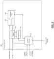
- FIG. 1is a block diagram of an example heating, ventilation, and air conditioning (HVAC) system.
- HVACheating, ventilation, and air conditioning
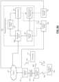
- FIG. 2is a functional block diagram of an example condenser unit of an example HVAC system that includes a heat pump.
- FIG. 3is a functional block diagram of an example indoor air quality (IAQ) sensor module that can be used with an HVAC system and/or other IAQ mitigation devices.
- IAQindoor air quality
- FIGS. 4 A- 4 Care functional block diagrams of an example IAQ control system.
- FIG. 5 Ais a functional block diagram of an example remote monitoring system.
- FIG. 5 Bis a functional block diagram of an example monitoring system.
- FIGS. 6 - 9are example user interfaces displayed by a user computing device during execution of an application based on data received from a remote monitoring system.
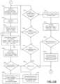
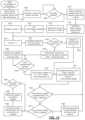
- FIGS. 10 A and 10 B togetherare a flowchart depicting an example method of controlling a mitigation device and estimating filter usage based on granular particulate matter measurements.
- FIGS. 11 A and 11 B togetherare a flowchart depicting another example method of controlling a mitigation device and estimating filter usage based on granular particulate matter measurements.
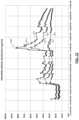
- FIG. 12is a graph showing levels of particulate matter of different size over a 12-hour period.
- FIG. 13is a flowchart depicting an example method of determining filter usage in a mitigation device based on IAQ parameters.
- FIG. 14is a graph showing the estimated weights of different air filters over time.
- FIG. 15is a table showing the estimated life of an air filter with a minimum efficiency reporting value (MERV) of 7 under various operating conditions.
- FIG. 16is a table showing the estimated weight of an air filter over different periods of time.
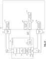
- FIG. 17is a functional block diagram of an example IAQ-based fan control system.
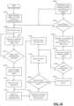
- FIG. 18is a flowchart depicting an example method of controlling a mitigation device based on measurements from a single IAQ sensor.
- FIG. 19is a flowchart depicting an example method of controlling a mitigation device based on measurements from two IAQ sensors.
- FIG. 20is a graph showing estimated percentages of pollutant removed by a mitigation device over a period of time.
- FIG. 21is a graph showing estimated pollutant levels over a period of time for an HVAC system operating with two different fan speeds.
- one or more mitigation devicesmay be capable of reducing levels of particulate matter in a conditioned space.
- an air purifiermay include one or more filters and may include a fan to increase airflow through the filters.
- a humidifiermay also mitigate particulate matter.
- a heating, ventilation, and air conditioning (HVAC) systemmay include one or more filters and a circulator blower that draws air through the filter(s). The circulator blower may be activated when the HVAC system is attempting to heat or cool the conditioned space (which may be described as mitigating deviations from a desired temperature range). The circulator blower may also be turned on independently of heating and cooling to distribute air around the conditioned space as well as to collect pollutants (such as particulate matter and, in some configurations, volatile organic compounds) in the filter(s).
- pollutantssuch as particulate matter and, in some configurations, volatile organic compounds
- mitigation devicesmay be activated in response to levels of particulate matter that exceed a certain threshold, while a lower threshold may be used to activate a single mitigation device.
- particulate matterthere is a wide variety of sizes of particulate matter. Certain sizes of particulate matter may be more deleterious to the health of humans and pets than other sizes. For example, particulate matter smaller than 2.5 micron ( ⁇ m) may be problematic because the smaller particulate matter can more deeply infiltrate a human's lungs. In various analyses, particulate matter smaller than 1 ⁇ m may be even more injurious than particulate matter sized between 1 ⁇ m and 2.5 ⁇ m.
- An indoor air quality (IAQ) control modulemay activate one or more mitigation devices to decrease levels of particulate matter.
- targets for acceptable levels of particulate mattermay be based on health advisories from governmental agencies, nonprofit organizations, and independent testing.
- the mitigation devicescan be controlled based on these different levels, which may be prioritized differently.
- the prioritizationmay be based on, for example, the respective health effects of different sizes of particulate matter.
- a measurement device described belowmay be able to measure particulate matter that is smaller than 10 ⁇ m, particulate matter that is smaller than 2.5 ⁇ m, and particulate matter that is smaller than 1 ⁇ m.
- the particulate matter sensorsmay measure or calculate levels of particulate matter within closed-ended ranges. For example, a measured or calculated value may be produced for particulate matter smaller than 10 ⁇ m but larger than 2.5 ⁇ m.
- the sizes of particulate matter described belowwill be defined only by an upper bound, making each particulate matter level cumulative of the levels of particulate matter of smaller size.
- the level of particulate matter smaller than 2.5 ⁇ mwill be cumulative of the level of particulate matter smaller than 1 ⁇ m
- the level of particulate matter smaller than 10 ⁇ mwill be cumulative of the level of particulate matter smaller than 2.5 ⁇ m.
- the lower bound of the rangeis simply the smallest particulate matter size that the sensor can detect.
- the mitigation devicesmay be controlled to focus mitigation efforts on that size of particulate matter.
- This size of particulate matter(referred to in shorthand as PM1) will be used in the below description, recognizing that the control system may be configured to focus on particulate matter of other sizes based on scientific research, environmental conditions in and around the building, and sensitivities of occupants of the building.
- the IAQ control modulemay perform that control or instruct an operator (such as an HVAC contractor) to so configure the mitigation device.
- the level of PM1may be used as a control variable, optimizing the level of PM1 preferentially over other sizes of particulate matter.
- the circulator blower of an HVAC systemmay be activated in response to undesirable levels of particulate matter.
- the circulator blowermay be maintained in the active state until PM1 falls below a predetermined acceptable level.
- the circulator blowermay remain activated until the apparent effectiveness of the HVAC system to remove PM1 falls below a threshold. For example, the amount of decrease in measured levels of PM1 may be observed over time and once the amount of decrease of PM1 stays below a predetermined threshold over a predetermined period of time, the circulator blower activation may be ended.
- the IAQ control modulemay assert a circulator blower activation signal to activate the circulator blower.
- the circulator blower activation signalmay be similar to or implemented as a call for fan.
- the call for fanmay be made by a thermostat to indicate that the fan should remain running even when the HVAC system is not heating or cooling the conditioned space. If the HVAC system is already heating or cooling the conditioned space, the circulator blower will already be active and the circulator blower activation signal may have no additional effect.
- the circulator blower activation signalmay cause the speed of the circulator blower to increase. This increased speed increases airflow through the filter and accelerates removal of particulate matter.
- the circulator blower activationmay be ended by deasserting the circulator blower activation signal.
- the circulator blower activation signalis activated in response to undesirable levels of particulate matter.
- the circulator blower activation signalis only deasserted once the level of particulate matter smaller than 10 ⁇ m is acceptable, the level of particulate matter smaller than 2.5 ⁇ m is acceptable, and the proportion of PM1 is less than a threshold percentage of particulate matter smaller than 2.5 ⁇ m. For example, when PM1 makes up more than 90% of the particulate matter smaller than 2.5 ⁇ m, the circulator blower activation signal may remain asserted to attempt to remove the undesirable PM1.
- the amount of particulate matter in the airis measured with finer granularity, estimates of how much particulate matter is captured by filters may be more accurate. Therefore, while the circulator blower is drawing air through the filter, the amount of particulate matter in the air and the characteristics of the filter may be used to estimate how much particulate matter is captured by the filter, according to the amounts (and associated weights) of particulate matter of different sizes.
- the usage of a filtermay be determined based on an estimated weight of particulate matter trapped by the filter, and a filter capacity may be determined according to how much weight the filter can be expected to carry without substantive reductions in effectiveness or airflow.
- the IAQ control module and/or the thermostatmay upload data to a remote location.
- the remote locationmay be accessible via any suitable network, including the Internet.
- the remote locationincludes one or more computers, which will be referred to as servers.
- the serversimplement a monitoring system on behalf of a monitoring company. Additionally or alternatively, a user computing device may serve as the monitoring system.
- the monitoring systemreceives and processes the data from the controller and/or thermostat of customers who have such systems installed.
- the monitoring systemcan provide performance information, diagnostic alerts, and error messages to one or more users associated with the building and/or third parties, such as designated HVAC contractors.
- a server of the monitoring systemincludes a processor and memory.
- the memorystores application code that processes data received from the controller and/or the thermostat.
- the processorexecutes this application code and stores received data either in the memory or in other forms of storage, including magnetic storage, optical storage, flash memory storage, etc. While the term server is used in this application, the application is not limited to a single server.
- a collection of serversmay together operate to receive and process data from multiple buildings.
- a load balancing algorithmmay be used between the servers to distribute processing and storage.
- the present applicationis not limited to servers that are owned, maintained, and housed by a monitoring company. Although the present disclosure describes diagnostics, processing, and alerting occurring in a remote monitoring system, some or all of these functions may be performed locally using installed equipment and/or customer resources, such as on a customer computer or computers.
- Customers and/or HVAC contractorsmay be notified of current and predicted issues (e.g., dirty filter) affecting effectiveness or efficiency of the HVAC system and/or other mitigating devices, and may receive notifications related to routine maintenance.
- the methods of notificationmay take the form of push or pull updates to an application, which may be executed on a smartphone, tablet, another type of mobile device, or on a computer (e.g., laptop or desktop).
- Notificationsmay also be viewed using web applications or on local displays, such as on the thermostat and/or other displays located throughout the building. Notifications may also include text messages, emails, social networking messages, voicemails, phone calls, etc.
- the monitoring companycan determine whether various components are operating at their peak performance.
- the monitoring companycan advise the customer and a contractor when performance is reduced. This performance reduction may be measured for the system as a whole, such as in terms of efficiency, and/or may be monitored for one or more individual components.
- the monitoring systemmay detect and/or predict failures of one or more components of the system.
- the customercan be notified and potential remediation steps can be taken immediately.
- components of the HVAC systemmay be shut down to prevent or minimize damage, such as water damage, to HVAC components.
- a contractorcan also be notified that a service call may be required.
- the contractormay schedule a service call to the building.
- the monitoring systemmay provide specific information to a contractor, such as identifying information of the customer's components, including make and model numbers, as well as indications of the specific part numbers of components. Based on this information, the contractor can allocate the correct repair personnel that have experience with the specific components and/or the system. In addition, a service technician is able to bring replacement parts, avoiding return trips after diagnosis.
- the customer and/or contractormay be advised of relevant factors in determining whether to repair or replace some or all of the components. For example only, these factors may include relative costs of repair versus replacement, and may include quantitative or qualitative information about advantages of replacement equipment. For example, expected increases in efficiency and/or comfort with new equipment may be provided. Based on historical usage data and/or electricity or other commodity prices, the comparison may also estimate annual savings resulting from the efficiency improvement.
- the monitoring systemmay also predict impending failures. This allows for preventative maintenance and repair prior to an actual failure of a component. Alerts regarding detected or impending failures reduce the time when the HVAC system is out of operation and allows for more flexible scheduling for both the customer and contractor. If the customer is out of town, these alerts may prevent damage from occurring when the customer is not present to detect the failure of a component. For example, failure of heating components of the HVAC system in winter may lead to pipes freezing and bursting.
- Alerts regarding potential or impending failuresmay specify statistical timeframes before the failure is expected. For example only, if a sensor is intermittently providing bad data, the monitoring system may specify an expected amount of time before it is likely that the sensor effectively stops working due to the prevalence of bad data. Further, the monitoring system may explain, in quantitative or qualitative terms, how the current operation and/or the potential failure will affect operation of the HVAC system. This enables the customer to prioritize and budget for repairs.
- the monitoring companymay charge a periodic rate, such as a monthly rate. This charge may be billed directly to the customer and/or may be billed to the contractor. The contractor may pass along these charges to the customer and/or may make other arrangements, such as by requiring an up-front payment and/or applying surcharges to repairs and service visits.
- a periodic ratesuch as a monthly rate. This charge may be billed directly to the customer and/or may be billed to the contractor.
- the contractormay pass along these charges to the customer and/or may make other arrangements, such as by requiring an up-front payment and/or applying surcharges to repairs and service visits.
- the monitoring serviceallows the customer to remotely monitor real-time data within the building, outside of the building, and/or control components of the system, such as setting temperature and relative humidity setpoints and other IAQ setpoints, enabling or disabling heating, cooling, ventilation, air purification, etc.
- the customermay be able to track usage data for components of the system and/or historical data.
- monitored datamay be transmitted to a local device in the building.
- a smartphone, laptop, or proprietary portable devicemay receive monitoring information to diagnose problems and receive real-time performance data.
- datamay be uploaded to the cloud and then downloaded onto a local computing device, such as via the Internet from an interactive website.
- HVACencompasses all environmental comfort systems in a building, including heating, cooling, humidifying, dehumidifying, air exchanging, and purifying.
- Environmental comfort systemsinclude devices such as furnaces, heat pumps, humidifiers, dehumidifiers, ventilators, and air conditioners. HVAC systems as described in this application do not necessarily include both heating and air conditioning, and may instead have only one or the other.
- a forced air system with a gas furnaceis shown.
- Return airis pulled from the building through an air filter 104 by a circulator blower 108 .
- the air filter 104reduces the amount of particulate matter in the return air.
- the air filter 104is assigned a minimum efficiency reporting value (MERV) rating that is based on the filtration efficiency of the filter.
- MEVminimum efficiency reporting value
- Air filters with a higher MERV ratingremove a larger percentage of particulate matter than air filters with a lower MERV rating.
- a typical, low-cost HVAC air filtermay have a MERV rating of 7, removing only 50%-70% particulate matter 3 microns or larger in size and removing negligible amounts of particulate matter that is smaller than 3 microns.
- an air filter with a MERV rating of 14removes at least 90% of the particulate matter 3 microns or larger, 90% of the particulate matter between 3 microns and 1 micron in size, and 75%-85% of the particulate matter between 0.3 micron and 1 micron in size.
- Particulate matter that is 1 micron or smaller in sizeposes the greatest risk to health in humans.
- the return airmay also be drawn through a volatile organic compound (VOC) filter 106 .
- the VOC filter 106reduces the amount of VOCs in the return air.
- the VOC filter 106may be an absorbent type VOC filter.
- the VOC filter 106may be an activated charcoal filter, a zeolite filter, an alumina oxide filter, or a baking soda filter.
- Activated charcoal filtersare able to remove by absorption 9-10% of toluene, benzene, and o-xylene-three common VOCs found in a home.
- Activated charcoal filtersmay be unable to absorb alcohols, carbon monoxide, or inorganics.
- the air filter 104may include both a particulate matter filter and an absorbent type VOC filter, which may be integrated into a single filter frame.
- the circulator blower 108also referred to as a fan, is controlled by a control module 112 .
- the control module 112receives signals from a thermostat 116 .
- the thermostat 116may include one or more temperature setpoints specified by the user.
- the thermostat 116may be a WiFi thermostat having wireless networking capability.
- the thermostat 116may direct that the circulator blower 108 be turned on at all times or only when a heat request or cool request is present (automatic fan mode).
- the circulator blower 108can operate at one or more discrete speeds or at any speed within a predetermined range.
- the control module 112may actuate one or more switching relays (not shown) to control the circulator blower 108 and/or to select a speed of the circulator blower 108 .
- the thermostat 116provides the heat and/or cool requests to the control module 112 .
- the control module 112causes a burner 120 to ignite. Heat from combustion is introduced to the return air provided by the circulator blower 108 in a heat exchanger 124 .
- the heated airis supplied to the building and is referred to as supply air.
- the burner 120may include a pilot light, which is a small constant flame for igniting the primary flame in the burner 120 .
- a pilot lightwhich is a small constant flame for igniting the primary flame in the burner 120 .
- an intermittent pilotmay be used in which a small flame is first lit prior to igniting the primary flame in the burner 120 .
- a sparkermay be used for an intermittent pilot implementation or for direct burner ignition.
- Another ignition optionincludes a hot surface igniter, which heats a surface to a temperature high enough that gas introduced to the heated surface will combust.
- Fuel for combustionsuch as natural gas, may be provided by a gas valve 128 .
- an inducer blower 132creates a draft to exhaust the products of combustion.
- the inducer blower 132may be turned on prior to ignition of the burner 120 .
- the inducer blower 132may remain running while the burner 120 is operating.
- the inducer blower 132may continue running for a set period of time after the burner 120 turns off.
- An enclosurewhich will be referred to as air handler unit 136 , may include the air filter 104 , the VOC filter 106 , the circulator blower 108 , the control module 112 , the burner 120 , the heat exchanger 124 , the inducer blower 132 , an expansion valve 140 , an evaporator 144 , a condensate pan 146 , and a transformer 147 .
- the transformer 147is connected to an alternating current (AC) power line in order to provide AC power to the control module 112 and the thermostat 116 .
- ACalternating current
- the transformer 147may be a 10-to-1 transformer and therefore provide either a 12 V or 24 V AC supply depending on whether the air handler unit 136 is operating on nominal 120 V or nominal 240 V power.
- the air handler unit 136includes an electrical heating device (not shown) instead of or in addition to the burner 120 . When used in addition to the burner 120 , the electrical heating device may provide backup or secondary (extra) heat.
- the HVAC system of FIG. 1includes a split air conditioning system. Refrigerant is circulated through a compressor 148 , a condenser 152 , the expansion valve 140 , and the evaporator 144 .
- the evaporator 144is placed in series with the supply air so that when cooling is desired, the evaporator 144 removes heat from the supply air, thereby cooling the supply air.
- the evaporator 144is cold (generally, below the dew point of the air within the building), which causes water vapor to condense. This water vapor is collected in the condensate pan 146 , which drains or is pumped out.
- a control module 156receives a cool request from the control module 112 and controls the compressor 148 accordingly.
- the control module 156also controls a condenser fan 160 , which increases heat exchange between the condenser 152 and outside air.
- the compressor 148 , the condenser 152 , the control module 156 , and the condenser fan 160are generally located outside of the building, often in an enclosure referred to as a condensing unit 164 .
- control module 156may include a run capacitor, a start capacitor, and a contactor or relay.
- start capacitormay be omitted, such as when the condensing unit 164 includes a scroll compressor instead of a reciprocating compressor.
- the compressor 148may be a variable-capacity compressor and may respond to a multiple-level cool request. For example, the cool request may indicate a mid-capacity call for cooling or a high-capacity call for greater cooling. The compressor 148 therefore varies its capacity according to the cool request.
- the electrical lines provided to the condensing unit 164may include a 240 V mains power line and a 24 V switched control line.
- the 24 V control linemay correspond to the cool request shown in FIG. 1 .
- the 24 V control linecontrols operation of the contactor.
- the contactorWhen the control line indicates that the compressor should be on, the contactor contacts close, connecting the 240 V power supply to the compressor 148 .
- the contactormay connect the 240 V power supply to the condenser fan 160 .
- the condenser fan 160may be omitted.
- the contactormay have two sets of contacts, and can be referred to as a double-pole single-throw switch.
- the thermostat 116typically includes a temperature sensor and sometimes includes a relative humidity sensor.
- a heating (heat) modethe thermostat 116 generates a heat request when the temperature measured by the temperature sensor is less than a lower temperature limit.
- a cooling (cool) modethe thermostat 116 generates a cool request when the temperature measured by the temperature sensor is greater than an upper temperature limit.
- the upper and lower temperature limitsmay be set based on a setpoint temperature plus and minus a predetermined amount (such as 1, 2, 3, 4, 5 degrees Fahrenheit).
- the setpoint temperaturemay be set to a predetermined temperature by default and may be adjusted by a user.
- the air handler unit 136is located inside the building, while the condensing unit 164 is located outside the building.
- the present disclosureis not limited to that arrangement, however, and applies to other systems including, as examples only, systems where the components of the air handler unit 136 and the condensing unit 164 are located in close proximity to each other or even in a single enclosure.
- the single enclosuremay be located inside or outside of the building.
- the air handler unit 136may be located in a basement, garage, or attic.
- the air handler unit 136 and the condensing unit 164may be located near the earth, such as in a basement, crawlspace, garage, or on the first floor, such as when the first floor is separated from the earth by only a concrete slab.
- an air handler unitIn split HVAC systems, an air handler unit is often located indoors and a condensing unit is often located outdoors. In heat pump systems, the function of the air handler unit and the condensing unit are reversed depending on the mode of the heat pump. As a result, although the present disclosure uses the terms air handler unit and condensing unit, the terms indoor unit and outdoor unit could be used instead in the context of a heat pump. The terms indoor unit and outdoor unit emphasize that the physical locations of the components stay the same while their roles change depending on the mode of the heat pump. A reversing valve selectively reverses the flow of refrigerant from what is shown in FIG. 1 depending on whether the system is heating the building or cooling the building in a heat pump system.
- FIG. 2an example condensing unit 268 is shown for a heat pump implementation in which the HVAC system would include the condensing unit 268 in place of the condensing unit 164 of FIG. 1 .
- the condensing unit 268may be configured similarly to the condensing unit 164 of FIG. 1 .
- the mode of the heat pumpdetermines whether the condenser 152 of the condensing unit 268 is actually operating as a condenser or as an evaporator.
- a reversing valve 272is controlled by a control module 276 and determines whether the compressor 148 discharges compressed refrigerant toward the condenser 152 (cooling mode) or away from the condenser 152 (heating mode).
- the control module 276controls the reversing valve 272 and the compressor 148 based on the control signals.
- the control module 276may receive power from, for example, the transformer 147 of the air handler unit 136 or the incoming alternating current (AC) power line.
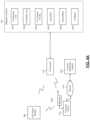
- FIG. 3includes a functional block diagram of an example indoor air quality (IAQ) sensor module 304 that can be used with an HVAC system and/or one or more other mitigation devices.
- the IAQ sensor module 304includes one or more of: a temperature sensor 308 , a relative humidity sensor 312 , a particulate sensor 316 , a VOC sensor 320 , and a carbon dioxide sensor 324 .
- the IAQ sensor modulemay also include one or more other IAQ sensors, such as occupancy, barometric pressure, airflow, light, sound, etc.
- the included sensors of the IAQ sensor module 304will be referred to collectively as IAQ sensors 326 .
- the IAQ sensor module 304may also include a sampling module 328 and a transceiver module 332 .
- a power supply 336may receive AC power from a standard wall outlet (or receptacle) 340 via a plug 344 .
- the standard wall outlet 340may provide nominal 120 V or nominal 240 V AC power.
- the power supply 336may include an AC-to-DC (direct current) converter that converts the AC power into DC power, such as 5 V, 12 V, or 24 V DC power.
- the power supply 336supplies power to the components of the IAQ sensor module 304 , including the sensors, the sampling module 328 , and the transceiver module 332 .
- the power supply 336may provide two or more different DC voltages to different components of the IAQ sensor module 304 .
- the power supply 336may be integrated with the plug 344 .
- the power supply 336may include a battery (or multiple batteries) and/or a solar cell (or multiple solar cells) that supplies power to the components of the IAQ sensor module 304 .
- the batterymay be replaceable or non-replaceable. In the example of the battery being non-replaceable, the battery may be re-chargeable, such as via a standard wall outlet.
- the IAQ sensor module 304may include a charger that charges the battery using power supplied, for example, via the standard wall outlet 340 .
- the IAQ sensor module 304may be portable for easy movement into different rooms of a building.
- the IAQ sensor module 304could also be placed outside the building, for example, to measure one or more conditions outside of the building, for calibration, or for other reasons.
- the temperature sensor 308measures a temperature of air at the IAQ sensor module 304 .
- the relative humidity sensor 312measures a relative humidity of air at the IAQ sensor module 304 .
- the particulate sensor 316measures an amount (for example, micrograms ( ⁇ g)) of particulate in air (for example, a cubic meter (m 3 )) at the IAQ sensor module 304 having a diameter that is less than a predetermined size (for example, 2.5 or 10 micrometers ( ⁇ m)).
- the VOC sensor 320measures an amount (for example, parts per billion (ppb)) of VOC in air at the IAQ sensor module 304 .
- the carbon dioxide sensor 324measures an amount (for example, parts per million (ppm)) of carbon dioxide in air at the IAQ sensor module 304 .
- the sampling module 328samples (analog) measurements of the IAQ sensors 326 .
- the sampling module 328may also digitize and/or store values of the measurements of the IAQ sensors 326 .
- the IAQ sensors 326may be digital sensors and output digital values corresponding to the respective measured parameters.
- the sampling module 328may perform a storage function or may be omitted.
- the IAQ sensor module 304may include one or more expansion ports to allow for connection of additional sensors and/or to allow connection to other devices. Examples of other devices include one or more other IAQ sensor modules, other types of IAQ sensors not included in the IAQ sensor module 304 , a home security system, a proprietary handheld device for use by contractors, a mobile computing device, and other types of devices.
- the transceiver module 332transmits frames of data corresponding to predetermined periods of time.
- Each frame of datamay include the measurements of the IAQ sensors 326 over a predetermined period.
- One or more calculationsmay be performed for the data of each frame of data, such as averages.
- Each frame(including the calculations and/or the measurements) may be transmitted to a monitoring system, as discussed further below.
- the measurements of the IAQ sensors 326may be sampled at a predetermined rate, such as 10 samples per minute or another suitable rate. In various implementations, individual sensors of the IAQ sensors 326 may be sampled at different rates.
- Each framemay correspond to a predetermined number of sets of samples (e.g., 10 ) or a predetermined window of time.
- the monitoring systemmay provide visual representations of the measurements over predetermined periods of time along with other data, as discussed further below.
- the transceiver module 332transmits each frame (including the calculations and/or the measurements) to an IAQ control module 404 (see FIG. 4 B ) and/or the thermostat 116 .
- the transceiver module 332transmits the frames wirelessly via one or more antennas, such as antenna 348 , using a proprietary or standardized, wired or wireless protocol, such as Bluetooth, ZigBee (IEEE 802.15.4), 900 Megahertz, 2.4 Gigahertz, or WiFi (IEEE 802.11).
- the IAQ sensor module 304may communicate directly with the IAQ control module 404 and/or the thermostat 116 or with a separate computing device, such as a smartphone, tablet, or another type of computing device.
- a gateway 408is implemented, which creates a wireless network for the IAQ sensor module 304 , IAQ control module 404 , and the thermostat 116 .
- the gateway 408may also interface with a customer router 412 using a wired or wireless protocol, such as Ethernet (IEEE 802.3).
- the IAQ control module 404may communicate with the customer router 412 using WiFi.
- the IAQ control module 404may communicate with the customer router 412 via the gateway 408 .
- the thermostat 116may also communicate with the customer router 412 using WiFi or via the gateway 408 .
- the IAQ control module 404 and the thermostat 116may communicate directly or via the gateway 408 .
- the IAQ sensor module 304 , the IAQ control module 404 , and/or the thermostat 116transmit data measured by the IAQ sensor module 304 and parameters of the IAQ control module 404 and/or the thermostat 116 over a wide area network, such as the Internet 416 .
- the IAQ sensor module 304 , the IAQ control module 404 , and/or the thermostat 116may access the Internet 416 using the customer router 412 of the customer.
- the customer router 412may already be present to provide Internet access to other devices (not shown) within the building, such as a customer computer and/or various other devices having Internet connectivity, such as a DVR (digital video recorder) or a video gaming system.
- DVRdigital video recorder
- the IAQ sensor module 304 , the IAQ control module 404 , and/or the thermostat 116transmit the data to a remote monitoring system 420 via the Internet 416 using the customer router 412 . Further discussion of the remote monitoring system 420 is provided below.
- the IAQ control module 404 and/or the thermostat 116controls operation of mitigation devices 424 based on the measurements from the IAQ sensor module 304 .
- the measurements of the IAQ sensor module 304may be provided to the thermostat 116 and the thermostat 116 may control operation of the mitigation devices 424 in various implementations (e.g., FIG. 4 A ).
- the IAQ control module 404can be omitted in such implementations. While the example of the thermostat 116 controlling the mitigation devices 424 will be discussed, alternatively the IAQ control module 404 may control operation of the mitigation devices 424 (e.g., FIG. 4 B ), or the thermostat 116 and the IAQ control module 404 may together control the mitigation devices 424 (e.g., FIG. 4 C ).
- the IAQ control module 404 and/or thermostat 116can communicate with the mitigation devices 424 wirelessly, by wire, or using a combination of wireless and wired connections.
- the IAQ control module 404 , the thermostat 116 , and the mitigation devices 424include respective transceivers.
- the mitigation devices 424include: (i) the condensing unit 164 , (ii) the air handler unit 136 (including the circulator blower 108 ), (iii) an air cleaner/purifier 428 , (iv) a humidifier 432 , (v) a dehumidifier 436 , and (vi) a ventilator 440 . Operation of the mitigation devices 424 may be controlled via the thermostat 116 , the IAQ sensor module 304 , and/or the remote monitoring system 420 . The mitigation devices 424 may communicate directly with the thermostat 116 , via the customer router 412 , and or via a remote back-end, such as the remote monitoring system 420 . The mitigation devices 424 may communicate using wired or wireless interfaces, which may be standardized or proprietary. For illustration only, the thermostat 116 will be the controlling device in the following discussion.
- the air cleaner/purifier 428is separate from the air handler unit 136 .
- the air handler unit 136may serve as the air cleaner/purifier 428 .
- the air cleaner/purifier 428draws in air and forces the air through a filter before expelling filtered air to the building.
- the filtermay be rated to remove a predetermined amount (for example, 95%) of particulate of the size measured by the particulate sensor 316 .
- Operation of the air cleaner/purifier 428may include whether the air cleaner/purifier 428 is on or off and, when on, a speed of the air cleaner/purifier 428 .
- the air cleaner/purifier 428may have a single speed or multiple discrete speeds.
- the thermostat 116may control whether the air cleaner/purifier 428 is on or off and, if on, the speed of the air cleaner/purifier 428 . As one example, the thermostat 116 may turn the air cleaner/purifier 428 on when the amount of particulate measured by the particulate sensor 316 is greater than a first predetermined amount of particulate. The thermostat 116 may leave the air cleaner/purifier 428 on until the amount of particulate measured by the particulate sensor 316 is less than a second predetermined amount of particulate that is less than the first predetermined amount of particulate. The thermostat 116 may turn the air cleaner/purifier 428 off when the amount of particulate measured by the particulate sensor 316 is less than the second predetermined amount of particulate.
- the thermostat 116may vary the speed of the air cleaner/purifier 428 based on the amount of particulate measured by the particulate sensor 316 . For example, the thermostat 116 may increase the speed of the air cleaner/purifier 428 as the amount of particulate increases and vice versa.
- the humidifier 432humidifies air within the building. Operation of the humidifier 432 may also reduce the amount of particulate in air within the building.
- the humidifier 432may be included with the air handler unit 136 or may be a stand-alone humidifier. For example, when included with the air handler unit 136 , the humidifier 432 may add moisture to the supply air before the supply air is outputted from vents to the building. The humidifier 432 may add moisture to air, for example, by supplying water to a medium (such as a pad) and forcing air through the hydrated medium. Alternatively, the humidifier 432 may spray water in the form of mist into air. In the example of a stand-alone humidifier, the humidifier 432 may spray water in the form of mist into the conditioned space.
- Operation of the humidifier 432may include whether the humidifier 432 is on or off. In various implementations, operation of the humidifier 432 may also include a humidification rate (for example, an amount of water supplied to the pad or into the air as mist over a period of time). The humidifier 432 may have a single humidification rate or multiple discrete humidification rates.
- a humidification ratefor example, an amount of water supplied to the pad or into the air as mist over a period of time.
- the humidifier 432may have a single humidification rate or multiple discrete humidification rates.
- the humidifier 432When the humidifier 432 is included with the air handler unit 136 , the humidifier 432 may turn on with the burner 120 , governed by a predetermined humidity setpoint. In various implementations, the thermostat 116 may control this setpoint or command the humidifier 432 to turn off. If the humidifier 432 is implemented separately from the air handler unit 136 , the thermostat 116 may control whether the humidifier 432 is on or off and a humidification rate when on. For example only, the thermostat 116 may turn the humidifier 432 on when the relative humidity measured by the relative humidity sensor 312 is less than a first predetermined relative humidity.
- the thermostat 116may leave the humidifier 432 on until the relative humidity measured by the relative humidity sensor 312 is greater than a second predetermined relative humidity that is greater than the first predetermined relative humidity.
- the thermostat 116may turn the humidifier 432 off when the relative humidity measured by the relative humidity sensor 312 is greater than the second predetermined relative humidity.
- the dehumidifier 436dehumidifies air within the building.
- the dehumidifier 436may be included with the air handler unit 136 or may be a stand-alone dehumidifier.
- the dehumidifier 436may draw moisture from the supply air (or add dry air to the supply air) before the supply air is outputted from vents to the building. Operation of the dehumidifier 436 may include whether the dehumidifier 436 is on or off.
- the thermostat 116may control whether the dehumidifier 436 is on or off. For example only, the thermostat 116 may turn the dehumidifier 436 on when the relative humidity measured by the relative humidity sensor 312 is greater than a third predetermined relative humidity.
- the third predetermined relative humiditymay be the same as the second predetermined relative humidity or different than (for example, greater than) the second predetermined relative humidity.
- the thermostat 116may leave the dehumidifier 436 on until the relative humidity measured by the relative humidity sensor 312 is less than a fourth predetermined relative humidity that is less than the third predetermined relative humidity.
- the fourth predetermined relative humiditymay be the same as the first predetermined relative humidity or different than (for example, greater than) the first predetermined relative humidity.
- the ventilator 440vents air from within the building out of the building. This also draws air from outside of the building into the building.
- the ventilator 440may be included with the air handler unit 136 (for example, the inducer blower 132 ) or a stand-alone ventilator. Examples of stand-alone ventilators include blowers that blow air from within the building out of the building (for example, range hoods fans, bathroom fans, etc.). Operation of the ventilator 440 may include whether the ventilator 440 is on or off and, when on, a speed.
- the ventilator 440may have a single speed or multiple discrete speeds.
- the thermostat 116may control whether the ventilator 440 is on or off and, if on, the speed of the ventilator 440 . As one example, the thermostat 116 may turn the ventilator 440 on when the amount of VOCs measured by the VOC sensor 320 is greater than a first predetermined amount of VOCs. The thermostat 116 may leave the ventilator 440 on until the amount of VOCs measured by the VOC sensor 320 is less than a second predetermined amount of VOCs that is less than the first predetermined amount of VOCs.
- the thermostat 116may turn the ventilator 440 on when the amount of carbon dioxide measured by the carbon dioxide sensor 324 is greater than a first predetermined amount of carbon dioxide.
- the thermostat 116may leave the ventilator 440 on until the amount of carbon dioxide measured by the carbon dioxide sensor 324 is less than a second predetermined amount of carbon dioxide that is less than the first predetermined amount of carbon dioxide.
- the mitigation devices 424are described only as examples. One or more of the example mitigation devices may be omitted. One or more other types of mitigation devices may be included. Additionally, while the example of only one of each type of mitigation device is provided, two or more of a given type of mitigation device may be included and controlled.
- Changes in temperature and/or humidityalso cause changes in particulate matter, VOCs, and/or carbon dioxide.
- a change in temperaturemay cause a change in VOCs, relative humidity, particulate, and/or carbon dioxide.
- a change in relative humiditymay cause a change in particulate matter, VOCs, and/or carbon dioxide.
- particulate mattermay increase as relative humidity increases and vice versa.
- the thermostat 116therefore may control operation of the mitigation devices 424 based on all of the parameters measured by the IAQ sensor module 304 in an attempt to: adjust the temperature to within a predetermined temperature range, adjust the relative humidity to within a predetermined relative humidity range, adjust the amount of particulate (if measured) to less than a predetermined amount of particulate, adjust the amount of VOCs (if measured) to less than a predetermined amount of VOCs, and to adjust the amount of carbon dioxide (if measured) to less than a predetermined amount of carbon dioxide.
- FIG. 5 Aincludes a functional block diagram of an example monitoring system.
- the IAQ control module 404 and/or the thermostat 116are shown transmitting, using the customer router 412 , data to the remote monitoring system 420 via the Internet 416 .
- the IAQ control module 404 and/or the thermostat 116may transmit the data to an external wireless receiver.
- the external wireless receivermay be a proprietary receiver for a neighborhood in which the building is located, or may be an infrastructure receiver, such as a metropolitan area network (such as WiMAX) receiver, a WiFi access point, or a mobile phone base station.
- WiMAXmetropolitan area network
- the remote monitoring system 420includes a monitoring server 508 that receives data from the IAQ control module 404 and/or the thermostat 116 and maintains and verifies network continuity with the IAQ control module 404 and/or the thermostat 116 .
- the monitoring server 508executes various algorithms to store setpoints for the building and to store measurements from the thermostat 116 and/or the IAQ sensor module 304 .
- the monitoring server 508may notify a review server 512 when one or more predetermined conditions are satisfied.
- This programmatic assessmentmay be referred to as an advisory.
- Some or all advisoriesmay be triaged by a technician to reduce false positives and potentially supplement or modify data corresponding to the advisory.
- a technician device 516 operated by a technicianmay be used to review the advisory and to monitor data (in various implementations, in real time) from the IAQ control module 404 and/or the thermostat 116 via the monitoring server 508 .
- a technician using the technician device 516may review the advisory. If the technician determines that a problem or fault is either already present or impending, the technician instructs the review server 512 to send an alert to a customer device 524 that is associated with the building. The technician may determine that, although a problem or fault is present, the cause is more likely to be something different than specified by the automated advisory. The technician can therefore issue a different alert or modify the advisory before issuing an alert based on the advisory. The technician may also annotate the alert sent to the customer device 524 with additional information that may be helpful in identifying the urgency of addressing the alert and presenting data that may be useful for diagnosis or troubleshooting.
- minor problemsmay not be reported to the customer device 524 so as not to alarm the customer or inundate the customer with alerts.
- the review server 512(or a technician) may determine whether a problem is minor based on a threshold. For example, an efficiency decrease that is less than a predetermined threshold may not be reported to the customer device 524 .
- the technician device 516may be remote from the remote monitoring system 420 but connected via a wide area network.
- the technician device 516may include a computing device such as a laptop, desktop, smartphone, or tablet.
- the customercan access a customer portal 528 , which provides historical and real-time data from the IAQ control module 404 and/or the thermostat 116 .
- the customer portal 528may also provide setpoints and predetermined ranges for each of the measurements, local outdoor air quality data, statuses of the mitigation devices 424 (e.g., on or off), and other data to the customer device 524 .
- the customer portal 528may be accessed using a web browser and/or a proprietary client application.
- the customermay change the setpoints, predetermined ranges, and other data collected from the customer device 524 .
- the monitoring server 508transmits changed setpoints and predetermined ranges to the thermostat 116 and/or the IAQ control module 404 for use in controlling operation of the mitigation devices 424 .
- the remote monitoring system 420includes an environmental data server 520 that obtains local environmental data for the geographical area surrounding the building.
- the environmental data server 520may obtain the local environmental data from one or more environmental data sources 532 via a wide area network, such as the Internet 416 .
- the geographical location of the buildingmay be specified by, for example, an address, zip code, coordinates, or other geographical identifier of the building.
- the remote monitoring system 420may obtain the geographical location of the building, for example, via the customer device 524 before providing data to the customer device 524 .
- the local environmental dataincludes, for example, air temperature, relative humidity, amount of VOCs in the air, amount of particulate matter (which may be restricted to certain sizes measurable by the particulate sensor 316 ), amount of carbon dioxide, barometric pressure, allergen information, and weather forecast information.
- FIG. 5 Bincludes a functional block diagram of an example monitoring system where the customer device 524 serves as a monitoring system and provides the functionality of the remote monitoring system.
- the thermostat 116 and/or the IAQ control module 404transmit data to the customer device 524 directly, such as via a Bluetooth connection, WiFi, or another wireless connection or via the Internet 416 .
- the customer device 524may obtain the local environmental data from the environmental data sources 532 via a wide area network, such as the Internet 416 .
- FIG. 6includes an example user interface displayed by the customer device 524 based on data from the customer portal 528 .
- the following functionsmay be performed by the customer device 524 during execution of an installed IAQ application.
- the customer device 524may display real-time values of the temperature, relative humidity, amount of VOCs, amount of particulate, and amount of carbon dioxide (CO 2 ) measured by the IAQ sensor module 304 . In FIG. 6 , these are illustrated in the row labeled “Indoor” as they represent parameters within the building.
- the real-time valuesare received by the customer device 524 from the monitoring server 508 via the customer portal 528 .
- the customer device 524may also display real-time values of the temperature, relative humidity, amount of VOCs, amount of particulate, and amount of carbon dioxide (CO 2 ) of the air surrounding the building. In FIG. 6 , these are illustrated in the row labeled “Outdoor” as they represent parameters outside of the building.
- the real-time valuesare received by the customer device 524 from the monitoring server 508 via the customer portal 528 .
- the customer device 524may also display present setpoints for beginning heating (Heat) of the building, cooling (Cool) of the building, humidification (Humidify), dehumidification (Dehumidify), VOC removal (VOCs), particulate removal (Particulate), and carbon dioxide removal (Carbon Dioxide).
- HeatingHeating
- Coolcooling
- HumidifyHumidify
- DehumidificationDehumidify
- Particulateparticulate removal
- Carbon DioxideCarbon Dioxide
- a range of desired values for a measurementmay be set based on the corresponding setpoint. For example, a range of desired values for humidification may be bounded by the humidify setpoint plus and minus a predetermined amount. A range of desired values for particulate may be bounded by the particulate setpoint plus and minus a predetermined amount.
- the customer device 524may allow a user to adjust one or more of the setpoints via the customer device 524 .
- the customer device 524may provide positive and negative adjustment inputs in association with one or more of the setpoints to allow for adjustment of the present setpoints.
- FIG. 6includes the example of “+” serving as the positive adjustment input and “ ⁇ ” serving as the negative adjustment input. Adjustment inputs labeled and configured differently, however, may be used.
- the customer device 524may transmit a command to the monitoring server 508 to adjust (increment or decrement) the setpoint by a predetermined amount. For example, in response to receipt of input indicative of user interaction with the positive adjustment input associated with the heating temperature setpoint, the customer device 524 may transmit a command to the monitoring server 508 to increment the heating temperature setpoint by a first predetermined amount. In response to receipt of input indicative of user interaction with the negative adjustment input associated with the heating temperature setpoint, the customer device 524 may transmit a command to the monitoring server 508 to decrement the heating temperature setpoint by the first predetermined amount. As another example, in response to receipt of input indicative of user interaction with the positive adjustment input associated with the humidification relative humidity setpoint, the customer device 524 may transmit a command to the monitoring server 508 to increment the humidification relative humidity setpoint by a second predetermined amount.
- the monitoring server 508relays (transmits) received commands for adjusting setpoints to the thermostat 116 and/or the IAQ control module 404 via the Internet 416 .
- the thermostat 116 and/or the IAQ control module 404adjust the associated setpoints in response to the commands received from the monitoring server 508 .
- FIG. 7includes an example user interface displayed by the customer device 524 during execution of the application based on data from the customer portal 528 when the building includes multiple IAQ sensor modules.
- the measurements from each IAQ sensor moduleare shown in a separate column.
- each columnincludes a customizable label.
- the columns labelsare numerical values—for example, 1, 2, and 3.
- a usermay use the customer device 524 to edit the label of each column to aid in identifying the location of each IAQ sensor—for example, “Living Room” or “Kitchen”.
- one or more of the IAQ sensorsmay be omitted from an IAQ sensor module.
- the associated IAQ sensor moduleonly includes a particulate sensor and a carbon dioxide sensor.
- the temperature, relative humidity, and VOC readings of zeroindicate that the IAQ sensor module does not include a temperature sensor, a humidity sensor, or a VOC sensor.
- the user interfacemay only display icons associated with the sensors included in each IAQ sensor.
- FIG. 8includes an example user interface displayed by the customer device 524 during execution of the application based on additional data from the customer portal 528 indicative of present statuses of control modes and present statuses of various devices of the building.
- the present status of a control mode or devicemay be on (currently in use) or off (not currently in use).
- One type of indicatormay be used to indicate a present status of on, while another type of indicator may be used to indicate a present status of off.
- the customer device 524may display the additional data concurrently with the data from one or more IAQ modules, the local environmental data, and/or the setpoint data.
- the customer device 524selectively displays measurements of one or more IAQ sensor modules, local data, control modes, and/or statuses from a predetermined period of time.
- the predetermined period of timemay be, for example, the present day, a predetermined number of days, a predetermined number of hours before a present time, a predetermined number of minutes before the present time, or another suitable period.
- a predetermined periodmay be selected (for example, the present day) but a user may select a different predetermined period to cause the customer device 524 to display the data for the selected predetermined period.
- FIG. 9includes an example user interface displayed by the customer device 524 during execution of the application based on data from the customer portal 528 for the present day (from 12:01 AM of the present day to the present time).
- the customer device 524displays data selected by a user of the customer device 524 . By default, all data may be selected, but a user may be allowed to select less than all of the data for display.
- the customer device 524selectively displays a user interface for user selection of a priority for mitigating deviations in IAQ parameters.
- the customer device 524may display a user interface that allows user assignment of an order of prioritization for: (i) temperature control, (ii) relative humidity control, (iii) particulate control, (vi) VOC control, and (v) carbon dioxide control.
- Temperature controlmay refer to maintaining, as much as possible, the temperature within the building within a specified range.
- Relative humidity controlmay refer to maintaining, as much as possible, the relative humidity within the building within a specified range.
- Particulate controlmay refer to maintaining, as much as possible, the amount of particulate within the building less than a predetermined threshold.
- VOC controlmay refer to maintaining, as much as possible, the amount of VOCs within the building less than a threshold.
- Carbon dioxide controlmay refer to maintaining, as much as possible, the amount of carbon dioxide within the building less than a threshold.
- the order of prioritization for (i)-(v)may be preset to a default order.
- the thermostat 116 and/or the IAQ control module 404may control the mitigation devices 424 based on the prioritization. For example, when particulate control is the first priority, the thermostat 116 may control the mitigation devices 424 to decrease particulate as quickly as possible as opposed to, for example, controlling the mitigation devices 424 to more quickly adjust temperature or relative humidity or to more quickly decrease the amount of VOCs and/or the amount of carbon dioxide.
- the user interfaces provided by the customer device 524provide visual information to the user regarding real-time measurements, historical measurements over a period of time, trends, and efficacy of IAQ mitigation and control.
- the user interfacesalso enable the user to adjust setpoints to be used to control the mitigation devices 424 to control comfort and IAQ within the building.
- the user interfacesalso enable the user to adjust prioritization of which IAQ conditions are mitigated and the sequence in which the IAQ conditions are mitigated.
- Relative humidity and temperaturemay both have an effect on the amount of VOCs, the amount of carbon dioxide, and the amount of particulate.
- the thermostat 116 and/or the IAQ control module 404controls the mitigation devices 424 to mitigate deviations of the temperature outside of the desired temperature range and deviations of the relative humidity outside of the desired relative humidity range.
- controlling temperature and/or humiditymay have adverse effects on VOCs, particulate, and CO 2 .
- the thermostat 116may need to coordinate control modes based on the prioritization of IAQ objectives.
- the thermostat 116controls the mitigation devices 424 based on the control modes.
- the control modesinclude the cooling mode, the heating mode, an extra heating mode, a humidify mode, a dehumidify mode, an extra dehumidify mode, a Departicle (or remove particulate) mode, a DeCO 2 (or remove carbon dioxide) mode, an extra DeCO 2 mode, a DeVOC (or remove VOC) mode, and an extra DeVOC mode.
- the thermostat 116 and/or the IAQ control module 404activate only one of the control modes at a time and determine a sequence for activating control modes when at least one of (I) and (II) is true and at least one of (A), (B), and (C) is true:
- the thermostat 116 and/or the IAQ control module 404also activates an associated one of the control modes when one of (I), (II), (A), (B), and (C) is true and the other ones of (I), (II), (A), (B), and (C) are not true and when two or more of (I), (II), (A), (B), and (C) are true and the other ones of (I), (II), (A), (B), and (C) are not true.
- the thermostat 116 and/or the IAQ control module 404operates the burner 120 and/or the heat pump to generate heat.
- the circulator blower 108may operate at a predetermined medium speed when the heating mode is active.
- the heating modemay be activated when the temperature is less than the lower temperature limit of the heating temperature range.
- the thermostat 116 and/or the IAQ control module 404may additionally (to the burner 120 and/or the heat pump and the circulator blower 108 ) operate an electric heater to generate additional heat.
- the extra heating modemay be activated when the outside temperature is less than a predetermined threshold.
- the heating mode and the extra heating modemay be deactivated when the temperature becomes greater than the upper temperature limit of the heating temperature range. In other words, the temperature range creates hysteresis, preventing short cycling of the heat.
- the thermostat 116 and/or the IAQ control module 404operates the condensing unit 164 .
- the thermostat 116may control the reversing valve 272 to provide cooling.
- the circulator blower 108may operate at a predetermined high speed when the cooling mode is active. The predetermined high speed is greater than the predetermined medium speed.
- the cooling modemay be activated when the temperature is greater than the upper temperature limit of the cooling temperature range.
- the cooling modemay be deactivated when the temperature becomes less than the lower temperature limit of the cooling temperature range.
- the cooling modemay naturally have a dehumidifying effect.
- the thermostat 116 and/or the IAQ control module 404operates the humidifier 432 .
- the thermostat 116also operates the circulator blower 108 at a predetermined speed, such as the predetermined high speed when the humidify mode is active.
- the humidify modemay be activated when the relative humidity is less than the first predetermined relative humidity.
- the humidify modemay be deactivated when the relative humidity becomes greater than the second predetermined relative humidity. Other options for humidification without the use of the humidifier 432 are discussed below.
- the thermostat 116 and/or the IAQ control module 404may operate the dehumidifier 436 . Additionally or alternatively, while the dehumidify mode is active, the thermostat 116 may toggle operation of the circulator blower 108 between operation at a predetermined low speed for a predetermined period and the predetermined high speed for the predetermined period.
- the predetermined periodmay be, for example, 5 minutes or another suitable period.
- the dehumidify modemay be activated when the relative humidity is greater than the third predetermined relative humidity.
- the thermostat 116 and/or the IAQ control module 404may also operate the circulator blower 108 at the predetermined high speed.
- the thermostat 116may additionally operate the compressor 148 and/or an electric heater to provide more rapid dehumidification when the extra dehumidify mode is active. Additionally, or alternatively, the thermostat 116 may transition to the cooling mode.
- the dehumidify modemay be activated when the relative humidity is at least a predetermined amount (for example, 1 percent) greater than the third predetermined relative humidity.
- the dehumidify mode and the extra dehumidifymay be deactivated when the relative humidity becomes less than the fourth predetermined relative humidity.
- the thermostat 116 and/or the IAQ control module 404may operate the circulator blower 108 at a predetermined speed, such as the predetermined high speed. Additionally or alternatively, the thermostat 116 may operate the air cleaner/purifier 428 when the Departicle mode is active.
- the Departicle modemay be activated when the amount of particulate is greater than the predetermined amount of particulate.
- the Departicle modemay be deactivated when the amount of particulate becomes less than the predetermined amount of particulate.
- the thermostat 116 and/or the IAQ control module 404may operate the inducer blower 132 at a predetermined speed, such as the predetermined low speed. Additionally or alternatively, the thermostat 116 may operate one or more ventilators, such as one or more bathroom fans or range hood fans. The DeVOC mode may be activated when the amount of VOCs is greater than the predetermined amount of VOCs.
- the thermostat 116 and/or the IAQ control module 404may operate the circulator blower 108 at the predetermined high speed.
- the thermostat 116may additionally operate one or more other ventilators to more rapidly decrease VOCs when the extra DeVOC mode is active.
- the extra DeVOC modemay be activated when the amount of VOCs remains greater than the predetermined amount of VOCs for greater than a predetermined period when the DeVOC mode is active, such as 1 hour.
- the extra DeVOC mode and the DeVOCmay be deactivated when the amount of VOCs becomes less than the predetermined amount of VOCs.
- the thermostat 116 and/or the IAQ control module 404may operate the circulator blower 108 at a predetermined speed, such as the predetermined low speed. Additionally or alternatively, the thermostat 116 and/or the IAQ control module 404 may operate one or more ventilators, such as one or more bathroom fans or range hood fans. The DeCO 2 mode may be activated when the amount of carbon dioxide is greater than the predetermined amount of carbon dioxide.
- the thermostat 116 and/or the IAQ control module 404may operate the circulator blower 108 at the predetermined high speed.
- the thermostat 116 and/or the IAQ control module 404may additionally operate one or more other ventilators to more rapidly decrease carbon dioxide when the extra DeCO 2 mode is active.
- the extra DeCO 2 modemay be activated when the amount of carbon dioxide remains greater than the predetermined amount of carbon dioxide for greater than a predetermined period when the DeCO 2 mode is active, such as 1 hour.
- the extra DeCO 2 mode and the DeCO 2may be deactivated when the amount of carbon dioxide becomes less than the predetermined amount of carbon dioxide.
- FIGS. 10 A and 10 Ba flowchart depicts example mitigation device control and air filter lifetime estimation based on granular particulate matter measurements.
- the mitigation deviceis the particulate matter filter of an HVAC system, which is activated by a circulator blower drawing air through the filter.
- an IAQ control modulesuch as the IAQ control module 404 .
- some or all of the controlmay instead occur in the thermostat 116 , in the remote monitoring system 420 , or in a personal electronic device, such as a smart phone or tablet.
- the IAQ control modulemay simply be implemented as software or firmware within, for example, the thermostat 116 .
- the controlmay activate the circulator blower of the HVAC system via a standard call for fan made by the thermostat 116 .
- the measured levels of particulate mattermay be received from the IAQ sensor module 304 or from multiple sensor modules.
- each sensor modulemay be dedicated to a respective range of sizes of particulate matter. These levels may be combined and, in cases where there are overlapping measurements, harmonized, being used by the IAQ control module. Alerts sent to an operator (such as a homeowner, resident, building operator, or HVAC contractor) may be sent directly to the operator or provided to the remote monitoring system 420 for distribution.
- Controlbegins in FIG. 10 A at 604 upon installation of a new air filter.
- a new air filtermay also be installed so that the IAQ control system can begin monitoring the life of the air filter.
- Installation of a first filtermay be standard because the cost of an air filter may be substantially less than the cost of the IAQ control system and installation.
- controlobtains system information for the HVAC system, including air flow information, dimensions of the air filter, and filter grade.
- the filter grademay be specified as a minimum efficiency reporting value (MERV) metric.
- the airflow and filter dimensionsmay remain the same and may therefore be obtained from storage.
- the filter grademay be specified by the user upon installation of the filter.
- a predetermined grademay be used as a default.
- a predetermined grade of MERV 14may be physically printed on the HVAC system to convey the recommended MERV rating to the operator servicing the HVAC system. Control may therefore assume that the operator will replace the filter with another MERV 14 filter.
- Controlcontinues at 608 , where control estimates the filter capacity (Filter_Capacity) based on the filter dimensions. For example, the filter capacity may be estimated based on total square footage of filtration area, where thicker filters provide for additional square footage.
- controldetermines estimated filter removal efficiencies for various sizes of particulate matter. These efficiencies may be estimated based on standards corresponding to the MERV rating. In general, each range of particulate matter sizes has a corresponding removal efficiency for a given MERV standard. Higher MERV standards generally have higher removal efficiencies for each size of particulate matter.
- the particulate matter removal efficiencyis determined for particles 10 ⁇ m smaller than (PM10_EFF), particulate matter smaller than 2.5 ⁇ m (PM2.5_EFF) and particulate matter smaller than 1 ⁇ m (PM1_EFF).
- the ranges of PMare, in microns, 0-10, 0-2.5, and 0-1, respectively. These ranges are different: overlapping but not co-extensive. In fact, each range is a subset of the next. Note that 0 is not truly the lower bound of the range because the sensitivity of the sensor defines the lower bound: detection of infinitesimally small particles may be possible at the Large Hadron Collider but is not feasible in residential or commercial systems.
- controlinitializes a total weight of filtered particulate matter (Total_Filtered_Weight) to 0.
- controlinitializes a counter variable to 0. The counter may be incremented on a periodic schedule while the circulator blower is running and may therefore be a proxy for how long the circulator blower has been running. The counter can then be used, based on that predetermined period, to estimate filter usage.
- controlmeasures the level of particulate matter smaller than 10 ⁇ m (PM10), the level of particulate matter smaller than 2.5 ⁇ m (PM2.5), and the level of particulate matter smaller than 1 ⁇ m (PM1).
- controldetermines the current state of the circulator blower. For example, if a call for heat, call for cool, or call for fan is currently asserted by the thermostat, the circulator blower would be expected to be on.
- controltransfers to 636 ; if the circulator blower is not already on, control transfers to 640 .
- controlasserts the circulator blower activation signal.
- the assertion of the circulator blower activation signalmay not have immediate effect.
- assertion of the circulator blower activation signalwill prevent the circulator blower from turning off.
- Controlcontinues at 644 , where an initial PM1 value (PM1_Initial) is set equal to the most recently measured value of PM1. Control then continues at 648 in FIG. 10 B .
- controldetermines whether PM10 is greater than a first predetermined threshold. If so, control transfers to 636 ; otherwise, control transfers to 652 .
- controldetermines whether PM2.5 is greater than a second predetermined threshold. If so, control transfers to 636 ; otherwise, control transfers to 656 .
- controldetermines whether PM1 is more than a predetermined percentage (such as 90%) of PM2.5. If so, control transfers to 636 ; otherwise, control transfers to 660 . In other words, any of the conditions 640 , 652 , and 656 will lead to assertion of the circulator blower activation signal at 636 .
- control delays for a predetermined sampling periodsuch as two minutes.
- SPsampling period
- the sampling periodmay be set based on how long it takes measurement devices to respond to changes in particulate matter in the air. For example, if a decrease in particulate matter is not registered for a minute or two, there is no need to sample the measurement more quickly.
- Controlcontinues at 664 , where the counter is incremented. Control then returns to 624 to acquire new measurements.
- controlinitializes a timer to a predetermined value (Steady_State_Period) and begins counting down the timer.
- Step 668where the most recently measured PM1 is stored into a holding variable (PM1_Previous).
- controldelays for the predetermined sampling period, which matches the predetermined sampling period of 660 .
- controlincrements the counter.
- controlmeasures and stores values for PM10, PM2.5, and PM1. This may be performed in the same manner as 624 .
- Controlcontinues at 684 , where control increments the total filtered weight by the product of the sampling period, the air flow through the filter, and a sum of estimated particulate matter removed by the filter per unit of time.
- the sumis calculated as the product of the effectiveness of the filter at removing PM10 and the difference between PM10 and PM2.5 plus the product of the effectiveness of the filter at removing PM 2.5 and the difference between PM2.5 and PM1 plus the product of the effectiveness of the filter at removing PM1 and the value of PM1.
- controlcalculates an amount of decrease (PM1_Decrease) caused by operation of the filter. This may be expressed as a percentage by multiplying 100% by PM1_Previous being divided into the difference between PM1_Previous and PM1.
- controldetermines whether the decrease in PM1 is more than a steady-state percentage of change, such as 5%. If so, the filter still appears to be removing PM1 and therefore control continues at 696 ; otherwise, control transfers to 700 .
- controlresets the timer to begin a new steady-state period and control returns to 668 .
- controldetermines whether the timer has expired. In other words, if the amount of PM1 decrease has been within the steady-state percentage for each sampling period throughout the length of the timer (steady-state period), the level of PM1 has reached steady-state and further operation of the circulator blower appears unlikely to affect the level. If, at 700 , the timer has expired, control transfers to 704 ; otherwise, control returns to 668 . At 704 , control deasserts the circulator blower activation signal. This allows the circulator blower to turn off in the absence of a call for heat, cool, or fan from the thermostat. Note, however, that deasserting the circulator blower activation signal does not necessarily turn off the circulator blower if a call for heat, cool, or fan is present.
- controlcalculates a filter usage variable (Filter_Usage) in terms of a percentage by multiplying 100% by total filtered weight divided by filter capacity.
- controldetermines whether the filter usage is greater than a predetermined percentage, such as 70%, 80%, or 90%. If so, control transfers to 716 ; otherwise, control transfers to 720 .
- controlcalculates the amount of remaining time expected for the filter before filtration or airflow is substantially affected. The remaining time is calculated by determining the product of the sampling period, the counter value and the difference between filter capacity and total filtered weight. This quantity is divided by total filtered weight to arrive at remaining time. When the estimate of total filtered weight exceeds the filter capacity, the remaining time actually becomes negative in this calculation.
- controlselectively generates an alert indicating that the filter is near capacity.
- the alertmay include the remaining time so that the HVAC operator can determine how urgently a new filter needs to be procured and installed.
- the alertmay be generated only at predetermined intervals, such as once per day or, if the remaining time is great enough, a longer interval such as once per week. Control then continues at 720 .
- controlcalculates the amount of PM1 removed (PM1_Removal_%). This may be determined as a percentage by dividing the difference between PM1_Initial and PM1 by PM1_Initial and multiplying by 100%. Control continues at 728 . If the calculated PM1 removal percentage is less than a predetermined percentage, the effectiveness of the filter may be questioned and control transfers to 732 ; otherwise, control returns to 660 in FIG. 10 A . At 732 , control generates an alert indicating that PM1 removal is low. The alert may indicate the calculated PM1 removal percentage and may also display the expected PM1 removal percentage.
- the predetermined percentage threshold of 728may be preprogrammed based on filter grade and other HVAC system parameters. For example, the predetermined percentage may be obtained from a lookup table indexed by MERV rating.
- FIGS. 11 A and 11 Banother implementation of particulate-matter-size-based HVAC system control and filter usage estimation is shown.
- Elements of FIG. 11 A that are similar to those of FIG. 10 Ause parallel reference numerals to those of FIG. 10 A .
- elements 804 , 808 , 812 , 816 , 820 , 824 , 828 , 832 , 836 , 840 , 844 , 852 , 856 , 860 , and 864may be implemented similarly to those elements of FIG. 10 A having the same last two digits of the reference numeral but beginning with 6 .
- FIG. 11 Aanother implementation of particulate-matter-size-based HVAC system control and filter usage estimation is shown.
- Elements of FIG. 11 A that are similar to those of FIG. 10 Ause parallel reference numerals to those of FIG. 10 A .
- Controlcontinues at 896 , where control calculates filter usage based on the total filtered weight divided by the filter capacity times 100%.
- Controlcontinues at 900 , where if the filter usage is greater than a predetermined percentage, control transfers to 904 ; otherwise, control transfers to 908 .
- the predetermined percentagemay be 70%, 80%, or 90%.
- controlcalculates a remaining lifetime expected from the filter, which may be calculated similarly to 716 of FIG. 10 B .
- Controlthen continues at 912 .
- controlselectively generates an alert indicating that the filter is near capacity. The alert may include the calculated remaining time. Control then continues at 908 .
- controldetermines whether the Blower_On variable is set to true. If so, control returns to 860 of FIG. 11 A . Otherwise, the blower was not initially on when the circulator blower activation signal was asserted and therefore exit conditions will be imposed before the circulator blower activation signal is deasserted. The exit conditions may be specified by 916 , 920 , and 924 . If at 908 , the Blower_On variable is set to false, control transfers to 916 .
- controldetermines whether PM10 is greater than a third predetermined threshold. If so, control transfers to 880 ; otherwise, control transfers to 920 .
- the third predetermined thresholdmay be the same as or different than (such as less than) the first predetermined threshold of 840 in FIG. 11 A .
- controldetermines whether PM2.5 is greater than a fourth predetermined threshold. If so, control returns to 880 ; otherwise, control transfers to 924 .
- the fourth predetermined thresholdmay be the same as or different than (such as less than) the second predetermined threshold of 852 of FIG. 11 A .
- controldetermines whether PM1 is more than a predetermined percentage (such as 90%) of PM2.5. If so, control returns to 880 ; otherwise, control transfers to 928 .
- controldeasserts the circulator blower activation signal.
- Controlcontinues at 932 , where a PM1 removal percentage is calculated as a difference between PM1 Initial and PM1 divided by PM1_Initial times 100%.
- controldetermines whether the calculated PM1 removal percentage is less than a predetermined percentage. If so, control transfers to 940 ; otherwise, control returns to 860 of FIG. 11 A .
- controlgenerates an alert indicating that the filter's PM1 removal is lower than expected. The alert may include the calculated value of PM1 removal percentage.
- plots 984 , 988 , and 992 of PM10, PM2.5, and PM1, respectively,are displayed with respect to time.
- a peak 996 of the PM10 plot 984is reached at approximately 2:24 PM.
- the peak 996may result from oil smoking in a pan.
- the peak at 996may exceed a predetermined threshold for acceptable PM10, PM2.5, or PM1 values, initiating particulate matter mitigation. Therefore, over time the values of the plots 984 , 988 , and 992 trend downward.
- the mitigation devicemay be turned off once the PM1 plot 992 achieves steady-state—that is, where each decrease in PM1 over a period of time (such as 20 minutes) is less than a threshold such as 5%.
- the mitigation devicemay be turned off once the value of PM1 is less than or equal to a predetermined percentage, such as 90%, of PM2.5.
- the IAQ control modulemay use PM10, PM2.5, and PM1 data, such as the data shown in FIG. 12 , to predict future PM levels. For example, over the course of a week the IAQ control module may determine that PM10 consistently increases every day around 2:30 PM (shown in FIG. 12 as peak 1060 ). The recurring increase in PM may be caused by regularly repeated activities, such as cooking. Based on the recurring PM spikes, the IAQ control module may determine that an increase in PM is likely to occur every day around 2:30 PM. The IAQ control module may initiate mitigation—for example, activating the circulator blower of an HVAC system—prior to the expected PM increases. This preemptive mitigation may reduce the time required to mitigate the increases in PM and maintain PM within a tighter envelope.
- mitigationfor example, activating the circulator blower of an HVAC system—prior to the expected PM increases. This preemptive mitigation may reduce the time required to mitigate the increases in PM and maintain PM within a tighter envelope.
- an indoor air quality (IAQ) sensor modulecan be used to determine the usage of a filter of a mitigation device, such as an HVAC system.
- the HVAC systemmay mitigate unwanted temperatures or humidity, and by cycling air, may mitigate other air quality issues. Further, drawing air through the HVAC system's filter may mitigate air pollutants.
- the IAQ sensor moduleincludes a particulate sensor that measures an amount (e.g., concentration) of particulate matter in the air and/or a volatile organic compound (VOC) sensor that measures an amount of VOCs in the air.
- VOCvolatile organic compound
- the IAQ sensor moduleis wirelessly connected to a thermostat of the HVAC system, such as via Bluetooth or WiFi.
- the IAQ sensor modulemay additionally or alternatively be wirelessly connected to an IAQ control module.
- the IAQ control module and/or the thermostatdetermine the usage of the filter in the mitigation device based on the measurements from the IAQ sensor module. For example, the IAQ control module and/or the thermostat may determine the amount of air passing though the filter and the level of air pollutant in the air, based on either the particulate matter or the VOCs measured by the IAQ sensor, to estimate the amount of air pollutant collected by the filter. In addition, the IAQ control module and/or the thermostat may determine a capacity of the filter and estimate how much time remains until the filter reaches the capacity.
- the amount of air passing through the filteris proportional to the speed of a fan (called a circulator blower) that draws or pushes air through the filter.
- the IAQ modulemay determine the speed of the fan and, therefore, the amount of air passing through the filter based on the current or power consumed by a motor of the fan. For example, the IAQ control module may measure the current that passes through the motor and determine the speed of the fan based on the measured current. Additionally, the IAQ control module may measure a voltage supplied to the motor and use the measured current and voltage to calculate the apparent power consumed by the motor. Alternatively, the IAQ module may use a power measurement integrated circuit (IC) to measure the real power consumed by the motor. The IAQ module then determines the speed of the fan based on either the apparent power or the real power.
- ICpower measurement integrated circuit
- the speed of the fanmay be inferred according to the operation mode of the HVAC system—for example, a certain fan speed may be used for heating, a certain fan speed may be used for cooling, and a same or different speed may be used for fan-only operation.
- the IAQ modulemay determine the speed of the circulator blower and, therefore, the amount of air passing through the filter based on the operation mode of the HVAC system.
- the IAQ control modulemay receive information about present operation mode of the HVAC system from a thermostat. Alternatively, the IAQ control module may determine the operation mode of the HVAC system based on power consumed by the HVAC system.
- the IAQ control modulemay receive power data from an energy monitor, such as a whole home energy monitor, that indicates whether the circulator blower of the HVAC system is running and indicates the present mode of the HVAC system.
- the IAQ control modulecan determine the speed of the circulator blower (or the airflow through the filter) based on the indicated operation mode.
- airflowmay be measured directly, such as with an airflow sensor.
- the rate of filter loadingcan be adjusted. For example, with a certain ambient level of particulate matter in the air, airflow that is 20% higher may result in 20% (or some fraction thereof, such as 3 ⁇ 4, leading to 15%) faster loading of the filter.
- the model of filter loadingcan include a gain factor based on airflow.
- the IAQ control module and/or the thermostatcan provide information on the filter usage as well as the measurements of the IAQ sensor and other data (e.g., statuses of mitigation devices, local outdoor air conditions, etc.) to one or more user devices (e.g., of tenants, occupants, customers, contractors, etc.) associated with the building.
- the buildingmay be a single-family residence, and the customer may be the homeowner, a landlord, or a tenant.
- the buildingmay be a light commercial building, and the customer may be the building owner, a tenant, or a property management company. Since the determined filter usage is based on operational conditions of the mitigation device, the system may notify a user when the filter needs to be changed based on actual filter usage rather than requiring the user to rely on other less accurate, conventional filter replacement schedules.
- FIG. 13is a flowchart depicting an example method of determining filter usage in a mitigation device based on measured IAQ parameters.
- controlmay be performed by the IAQ control module 404 .
- controlmay be performed by the thermostat 116 or by the IAQ control module 404 and the thermostat 116 .
- the example methodmay be implemented in a single point air purifier (such as the air cleaner/purifier 428 of FIG. 4 A ) or any other mitigation device that uses a particulate matter filter, an absorbent type VOC filter, or a combination particulate matter and absorbent type VOC filter.
- a filter, fan, air pollutant sensor, and control modulemay be collocated in a single device. The control module may operate according to the flowchart of FIG. 13 .
- the single point systemincludes a filter and a fan but may omit the control module (or the control module may be disabled).
- the single point systemcan then be controlled as a mitigation device by another controller, such as the IAQ control module 404 , which may also monitor the life of the filter using the control of FIG. 13 .
- the air pollutant sensormay be used to provide readings to the IAQ module 404 or may be omitted or disabled when the IAQ control module 404 has another source of pollutant level data.
- the IAQ control module 404may operate the single point system in addition to a whole-home system for faster response if air in the space surrounding the single point system (for example, the room in which the single point system is located) has a high level of pollutants.
- the IAQ control module 404may also operate the single point system in the absence of the whole-home system if the space surrounding the single point system has a higher pollutant level than other areas of the home.
- controlbegins at 1003 , with the installation of an IAQ control system.
- controlobtains system parameters of the HVAC system—for example, the airflow of the HVAC system and the dimensions of a filter of the HVAC system, such as the air filter 104 or the VOC filter 106 .
- the obtained airflowmay be a nominal airflow associated with the components of the HVAC system—for example, the air handler unit 136 .
- Controlcontinues with 1006 where control generates a notice to install a new filter in the HVAC system. In various implementations, the notice may be displayed on the customer device 524 and/or on the thermostat 116 .
- Controlcontinues with 1009 .
- controldetermines whether a new filter has been installed.
- the IAQ control systemmay prompt an operator to use the customer device 524 to confirm that a new filter has been installed.
- the operatormay be a building owner, such as a homeowner. In other implementations, the operator may be an HVAC contractor. If 1009 is false, control remains at 1009 . If 1009 is true, control progresses to 1012 .
- controlobtains information about the newly installed filter—for example, a MERV rating of an air filter or a weight of filtering material of a VOC filter.
- controlcontinues with 1015 where control determines a capacity of the installed filter (Filter_Capacity) based on the obtained filter dimensions.
- controlcontinues with 1018 where control determines the removal efficiency of the installed filter (removal efficiency %).
- the IAQ control module 404may determine the removal efficiency % based on either the obtained MERV rating or the filtering material of installed filter. Control then continues with 1021 .
- controlsets the total filtered weight of the installed filter (Total_Filtered_Weight) to zero and, at 1024 , control initializes a counter to zero.
- Controlcontinues with 1027 where the state of the circulator blower 108 is determined.
- the IAQ control module 404may communicate with the thermostat 116 to determine the state of the circulator blower 108 .
- Controlcontinues with 1033 where control determines whether the circulator blower 108 is on. If 1033 is false, control transfers to 1036 .
- controldelays for a predetermined period of time (T). For example, the predetermined period of time may be one minute or 30 seconds.
- Controlcontinues with 1051 , as described below. If 1033 is true, control progresses to 1039 .
- controlresets a timer, measures a level of air pollutant, and sets an average air pollutant (AAP) variable to the measured level.
- the IAQ control systemuses at least one sensor, such as the IAQ sensor module 304 , to measure the level of air pollutant.
- the measured air pollutantis particulate matter—for example, dust.
- the measured air pollutantis at least one type of VOC.
- two or more IAQ sensor modulesmay be used to measure air pollutant levels throughout a building and the IAQ control module 404 uses an average of the values received from the IAQ sensor modules.
- Controlcontinues with 1042 where control measures the air pollutant, as described above, and updates the AAP.
- controlmay use the nominal airflow associated with the components of the HVAC system as the value of airflow in equation 1. In other implementations, control may determine the value of airflow in equation 1 based on the speed of the circulator blower 108 . Control may determine the speed of the circulator blower by measuring the current or power consumed by a motor of the circulator blower 108 . Alternatively, control may determine the speed of the circulator blower 108 based on a present operation mode of the HVAC system—for example, cooling, heating, or fan only. Control may receive the present operation mode of the HVAC system from the thermostat 116 , Alternatively, control may determine the present operation mode of the HVAC system based on power data received from an energy monitor, such as a whole home energy monitor. The power data may include the present operation mode and/or the power consumed by the HVAC system. If the present operation mode is not included in the power data, control may infer the present operation mode based on the power consumed by the HVAC system.
- Controlcontinues with 1051 where control determines the remaining life of the filter based on the capacity of the filter and past usage.
- the IAQ control module 404may calculate Remaining_Time using equation 2 below.
- Remaining_Time( Filter_Capacity - Total_Filtered ⁇ _Weight ) * T * Counter Total_Filtered ⁇ _Weight ( 2 )
- controldetermines whether the filter has reached a predetermined usage level, such as 90% of the capacity of the filter. In other words, the IAQ control module 404 may determine if Total_Filtered_Weight is greater than or equal to 90% of Filter_Capacity. If 1054 is false, control returns to 1027 . If 1054 is true, control transfers to 1057 where control determines whether the filter is full by determining if Total_Filtered_Weight is greater than or equal to Filter_Capacity. If 1057 is false, control progresses to 1060 .
- a predetermined usage levelsuch as 90% of the capacity of the filter. In other words, the IAQ control module 404 may determine if Total_Filtered_Weight is greater than or equal to 90% of Filter_Capacity. If 1054 is false, control returns to 1027 . If 1054 is true, control transfers to 1057 where control determines whether the filter is full by determining if Total_Filtered_Weight is greater than or equal to Filter_Capacity. If 10
- controlselectively generates an alert indicating that the filter is near capacity.
- the alertmay be displayed on the customer device 524 and/or on the thermostat 116 .
- the IAQ control module 404may only generate the alert once per day—for example, the first time that control reaches 1060 each day. In other implementations, the IAQ control module 404 may generate the alert every time control reaches 1060 .
- the alertmay be displayed on the customer device 524 and/or on the thermostat 116 .
- controlcontinues with 1066 where control determines whether a new filter has been installed. For example, the IAQ control module 404 may prompt a user to use the customer device 525 to confirm that a new filter has been installed.
- controldetermines whether the new filter has been installed. If 1069 is false, control returns to 1063 . If 1069 is true, control returns to 1012 . In some implementations, in order to protect components of the HVAC system from damage, control may disable the HVAC system until a new filter is installed.
- FIG. 14is a graph showing the estimated weight of accumulated pollutant in four different air filters over a period of 12 months.
- the four air filters depicted in FIG. 14each measure 20 inches by 25 inches by one inch.
- Three of the filters depictedhave a MERV rating of 14 and one of the filters depicted has a MERV rating of 7.
- the pollutant weight in the MERV 14 rated filtersincrease at a faster rate than in the MERV 7 rated filter, even when subjected to the same operating conditions—an average measured particulate matter (PM) of 7 micrograms/m 3 and an average fan run time (RT) of 30%.
- the graphshows that an increase in either the average measured particulate matter or the average fan run time will result in an increase in the rate that the filter accumulates pollutants.
- FIG. 15is a table showing the estimated life in months of a MERV 7 rated air filter under various operating conditions.
- the tableshows that when the average particulate matter (PM) is 7 micrograms/m 3 and the average fan run time (RT) is 30%, the filter is estimated to reach capacity in 12 months. If either the average measured particulate matter or the average fan run time is increased, the life of the filter decreases due to the increased weight of the filtered particulate matter. For example, when the average measured particulate matter is 13 micrograms/m 3 and the average fan run time is 80%, the filter is estimated to reach capacity in 2.4 months.
- PMaverage particulate matter
- RTaverage fan run time
- actual measured air pollutant levels and fan runtimes of an HVAC systemmay be used to populate a table similar to that shown in FIG. 15 .
- the populated tablemay be presented to an operator of the HVAC system to inform the operator how the various measured parameters influence filter life.
- the operatormay use the information presented in the populated table to adjust the operation of the HVAC system to meet their specific IAQ needs. For example, the operator may increase the use of a fan-only mode of the HVAC system to reduce air pollutant levels.
- FIG. 16is a table showing the estimated weight of trapped pollutant in a MERV 14 rated air filter measuring 20 inches by 25 inches by one inch over various periods of time.
- the estimated trapped pollutant weightsare based on the filter being used in an air handler of a 3 ton AC unit that has an average air flow of 1100 cubic feet per minute (cfm), which is equivalent to 1868 cubic meters per hour (m 3 /h). Further, the estimated weights are based on an average particulate matter level of roughly 9.7 micrograms/m 3 and an average fan runtime of 30%.
- the pollutant weights in the tablewere calculated by multiplying the average particulate matter, the efficiency of the air filter, the airflow, and the average fan run time.
- the filteris estimated to trap 0.13 grams of pollutant each day, 0.91 grams per week, and 3.9 grams per month. Further, after six months of operation, under the above conditions, the filter is estimated to have accumulated 23.4 grams of pollutant and will be near the filter's estimated capacity of 25 grams.
- the HVAC control systemincludes the IAQ control module 404 , the thermostat 116 , and a first IAQ sensor module 1104 .
- the first IAQ sensor module 1104is located in a room 1106 that is supplied with air from the air handler unit 136 and is configured to measure and transmit air pollutant levels of the room 1106 —such as an amount of particulate matter and/or VOCs in the room 1106 .
- the first IAQ sensor module 1104may be implemented by the IAQ sensor module 304 .
- the first IAQ sensor module 1104may be located near the thermostat 116 . In other implementations, the first IAQ sensor module 1104 may be incorporated into the thermostat 116 .
- the HVAC control systemmay include a second IAQ sensor module 1108 and/or a third IAQ sensor module 1112 .
- the second IAQ sensor module 1108is located near a return vent 1116 that supplies air to the air handler unit 136 or in ductwork leading to the air filter 104 .
- the second IAQ sensor module 1108is configured to measure and transmit air pollutant levels-such as an amount of particulate matter and/or VOCs—in air upstream of the circulator blower 108 .
- the third IAQ sensor module 1112is located near a supply vent 1120 that emits air supplied from the air handler unit 136 or within ductwork leading to the supply vent 1120 .
- the third IAQ sensor module 1112is configured to measure and transmit air pollutant levels in air supplied by the air handler unit 136 —in other words, air pollutant levels in air downstream of the circulator blower 108 .
- the second IAQ sensor module 1108 and the third IAQ sensor module 1112may be IAQ sensors such as the IAQ sensor module 304 .
- FIG. 18is a flowchart depicting an example method of controlling a fan of a mitigation device based on IAQ measurements from a single IAQ sensor, such as the first IAQ sensor module 1104 .
- a single IAQ sensorsuch as the first IAQ sensor module 1104 .
- controlmay be performed by the IAQ control module 404 .
- controlmay be performed by the thermostat 116 or shared by a combination of the IAQ control module 404 and the thermostat 116 .
- Controlbegins at 1204 upon startup of the HVAC system.
- controlmay obtain an expected efficacy of an installed filter and store the value as Expected_Efficacy.
- the IAQ control module 404may receive the expected efficacy from the customer device 524 and/or the remote monitoring system 420 .
- Controlcontinues with 1208 where a counter is set to zero. The counter is used to determine a length of time during which a measured pollutant level does not appreciably decrease.
- controlmeasures a level of air pollutant and stores the value as an initial pollutant level (Initial_Level).
- the IAQ control module 404may receive a pollutant level transmitted from the first IAQ sensor module 1104 .
- the IAQ control modulemay receive a pollutant level transmitted from the second IAQ sensor module 1108 or the third IAQ sensor module 1112 .
- Controlthen progresses to 1216 where control determines whether the initial pollutant level (Initial_Level) is greater than or equal to a predetermined threshold. If so, control progresses to 1220 ; otherwise, control returns to 1212 .
- controlasserts a circulator blower activation signal.
- the circulator blower activation signalcontrols the state of a circulator blower, such as the circulator blower 108 .
- assertion of the circulator blower activation signalcauses the control module 112 to actuate one or more switching relays to turn on the circulator blower 108 .
- Deassertion of the circulator blower activation signalmay result in the control module 112 deactivating the circulator blower 108 .
- the circulator blower 108is turned off when the circulator blower activation signal is deasserted and no signal from the thermostat 116 (such as a call for heat, cool, or fan) is directing the circulator blower 108 to be turned on.
- Controlcontinues with 1224 .
- controlsets a first pollutant level (First_Level) equal to the initial pollutant level (Initial_Level).
- First_Levelthe initial pollutant level
- Controlthen continues with 1228 where control delays for a predetermined sampling period, such as one minute. The delay provides sufficient time for the level of air pollutant to be affected by the mitigation device—in other words, for particulate matter in the air to be trapped in the air filter 104 or for VOCs in the air to be trapped in the VOC filter 106 .
- Controlcontinues with 1232 where a second pollutant level is measured and stored as Second Level. Control continues with 1236 .
- controldetermines whether the second pollutant level (Second_Level) is less than the product of the first pollutant level (First_Level) and a predetermined factor—for example, whether Second Level is less than 95% of First Level. If 1236 is true, an appreciable decrease in pollutant level has been observed and control progresses to 1240 where the counter is reset to zero. Control then continues with 1244 where the first pollutant level (First_Level) is set equal to the second pollutant level (Second_Level). Control then returns to 1228 . If 1236 is false, control transfers to 1248 where the counter is incremented by one, indicating that a sampling period has passed without an appreciable decrease in pollutant level. Control continues with 1252 .
- controldetermines if the counter is greater than a predetermined value. If so, control progresses to 1256 ; otherwise, control returns to 1244 .
- the predetermined valuerepresents a number of consecutive sampling periods in which the level of measured air pollutant has not significantly decreased. In an example implementation, the predetermined value is five and the sampling period is one minute—in other words, control determines whether the level of air pollutant has not significantly decreased in any of the last five minutes. In various other implementations, the predetermined value and the predetermined sample period may be set to other, different values, such that control determining that 1252 is true indicates that activation of the fan of the mitigation device is no longer having a significant effect on the measured level of air pollutant.
- controlcauses the circulator blower activation signal to be deasserted.
- Controlcontinues with 1260 where control may calculate an efficacy of the installed filter based on the stored pollutant levels (Actual_Efficacy). For example, the IAQ control module 404 may calculate the value of Actual Efficacy using equation 1 below.
- Controlthen continues with 1264 .
- controldetermines whether the calculated efficacy of the filter (Actual Efficacy) is less than the expected efficacy of the filter (Expected_Efficacy). If 1264 is true, control progresses to 1268 where control generates an alert indicating that the filter is operating at less than the expected efficacy. For example, the thermostat 116 and/or the customer device 524 may display an indication that the filter is operating at less than the expected efficacy. The displayed indication may include the calculated efficacy of the filter (Actual_Efficacy). If 1264 is false, control returns to 1208 .
- the pollutant-level-based circulator blower control of FIG. 18may be used without calculating or evaluating efficacy of the filter.
- elements 1204 and 1260 - 1268would be omitted; then, control in FIG. 18 would begin at 1208 upon startup of the HVAC system and would return from 1256 directly to 1208 .
- FIG. 19is a flowchart depicting an example method of controlling a mitigation device based on IAQ measurements from two IAQ sensors—for example, the second IAQ sensor module 1108 and the third IAQ sensor module 1112 .
- control of the mitigation devicemay be based on the first IAQ sensor module 1104 and the second IAQ sensor module 1108 or based on the first IAQ sensor module 1104 and the third IAQ sensor module 1112 .
- controlmay be performed by the IAQ control module 404 . In other implementations, control may be performed by the IAQ control module 404 and/or the thermostat 116 .
- Controlbegins at 1304 upon startup of the HVAC system.
- controlmay obtain an expected efficacy of an installed filter and store the value as Expected_Efficacy.
- the IAQ control module 404may receive the expected efficacy from the customer device 524 and/or the remote monitoring system 420 .
- Controlcontinues with 1308 where control measures a level of air pollutant in air upstream of the circulator blower 108 —for example, near the supply vent 1120 —and stores the value as an initial pollutant level (Initial_Level).
- the IAQ control module 404may receive a pollutant level transmitted by the third IAQ sensor module 1112 .
- the IAQ control module 404may receive a pollutant level transmitted by the first IAQ sensor module 1104 .
- Controlprogresses to 1312 where control determines whether the initial pollutant level (Initial_Level) is greater than a predetermined level. If so, control progresses to 1316 ; otherwise, control returns to 1308 . At 1316 , control asserts a circulator blower activation signal. Control continues with 1320 where an upstream pollutant level (Up_Level) is set equal to the initial pollutant level (Initial_Level).
- Up_Levelupstream pollutant level
- the IAQ control module 404may receive a pollutant level transmitted by the second IAQ sensor module 1108 . In other implementations, the IAQ control module 404 may receive a pollutant level transmitted by the first IAQ sensor module 1104 . Control then continues with 1332 .
- controldetermines whether the downstream pollutant level (Down_Level) is less than the product of the upstream pollutant level (Up_Level) and a predetermined factor—for example, whether Down_Level is less than 95% of Up_Level. If 1332 is true, control progresses to 1336 where control measures a level of air pollutant upstream of the circulator blower 108 and stores the value as Up_Level. Control then returns to 1324 . If 1332 is false, control transfers to 1340 where control causes the circulator blower activation signal to be deasserted.
- Controlcontinues with 1344 where control may calculate an efficacy of the installed filter based on the stored pollutant levels (Actual_Efficacy). For example, the IAQ control module 404 may calculate the value of Actual Efficacy using equation 2 below.
- the pollutant-level-based circulator blower control of FIG. 19may be used without calculating or evaluating the efficacy of the filter.
- elements 1304 and 1324 - 1352may be omitted; control would instead begin in FIG. 19 at 1308 upon startup of the HVAC system and would return from 1340 directly to 1308 .
- FIG. 20is a graph showing an illustrative percentage of pollutant removed by a mitigation device over a period of time.
- the graphdepicts the reduction of pollutant during operation of the mitigation device, as measured at three separate locations: a point downstream of a filter of the migration device, within a room serviced by the mitigation device, and a point upstream of the filter of the mitigation device.
- the efficacy of the filteris the percentage of pollutant removed at the point where the slopes of at least one of the three lines approach zero. As shown in the graph, the slope of the downstream and room lines approach zero after 120 minutes and approximately 94 percent of the measured pollutant has been removed. In the mitigation scenario depicted in FIG. 20 , the efficacy of the filter is approximately 94 percent.
- FIG. 21is a graph showing illustrative pollutant levels over a period of time for an HVAC system operating at a high fan speed vs a low fan speed.
- operating the fan at high speed for 30 minutesresults in the pollutant level reaching a steady state—the point in time at which drawing air through the HVAC system's filter no longer appreciably reduces the measured pollutant level.
- steady stateis reached in 45 minutes when the fan is operated at low speed.
- operating the fan at high speedconsumes 500 watts and requires 0.25 kilowatt hours to reach the steady state
- operating the fan at low speedconsumes approximately 148 watts and requires 0.11 kilowatt hours to reach the steady state.
- assertion of the blower activation signalcauses the circulator blower 108 to operate at a low speed unless a signal from the thermostat 116 (such as a call for heat, cool, or fan) is directing the circulator blower 108 to operate at a higher speed.
- Spatial and functional relationships between elementsare described using various terms, including “connected,” “engaged,” “coupled,” “adjacent,” “next to,” “on top of,” “above,” “below,” and “disposed.” Unless explicitly described as being “direct,” when a relationship between first and second elements is described in the above disclosure, that relationship can be a direct relationship where no other intervening elements are present between the first and second elements, but can also be an indirect relationship where one or more intervening elements are present (either spatially or functionally) between the first and second elements.
- the phrase at least one of A, B, and Cshould be construed to mean a logical (A OR B OR C), using a non-exclusive logical OR, and should not be construed to mean “at least one of A, at least one of B, and at least one of C.”
- the term subsetdoes not necessarily require a proper subset. In other words, a first subset of a first set may be coextensive with (equal to) the first set.
- the direction of an arrowgenerally demonstrates the flow of information (such as data or instructions) that is of interest to the illustration.
- informationsuch as data or instructions
- the arrowmay point from element A to element B. This unidirectional arrow does not imply that no other information is transmitted from element B to element A.
- element Bmay send requests for, or receipt acknowledgements of, the information to element A.
- moduleor the term “controller” may be replaced with the term “circuit.”
- the term “module”may refer to, be part of, or include: an Application Specific Integrated Circuit (ASIC); a digital, analog, or mixed analog/digital discrete circuit; a digital, analog, or mixed analog/digital integrated circuit; a combinational logic circuit; a field programmable gate array (FPGA); a processor circuit (shared, dedicated, or group) that executes code; a memory circuit (shared, dedicated, or group) that stores code executed by the processor circuit; other suitable hardware components that provide the described functionality; or a combination of some or all of the above, such as in a system-on-chip.
- ASICApplication Specific Integrated Circuit
- FPGAfield programmable gate array
- the modulemay include one or more interface circuits.
- the interface circuit(s)may implement wired or wireless interfaces that connect to a local area network (LAN) or a wireless personal area network (WPAN).
- LANlocal area network
- WPANwireless personal area network
- IEEEInstitute of Electrical and Electronics Engineers
- 802.11-2016also known as the WIFI wireless networking standard
- IEEE Standard 802.3-2015also known as the ETHERNET wired networking standard
- Examples of a WPANare the BLUETOOTH wireless networking standard from the Bluetooth Special Interest Group and IEEE Standard 802.15.4.
- the modulemay communicate with other modules using the interface circuit(s). Although the module may be depicted in the present disclosure as logically communicating directly with other modules, in various implementations the module may actually communicate via a communications system.
- the communications systemincludes physical and/or virtual networking equipment such as hubs, switches, routers, and gateways.
- the communications systemconnects to or traverses a wide area network (WAN) such as the Internet.
- WANwide area network
- the communications systemmay include multiple LANs connected to each other over the Internet or point-to-point leased lines using technologies including Multiprotocol Label Switching (MPLS) and virtual private networks (VPNs).
- MPLSMultiprotocol Label Switching
- VPNsvirtual private networks
- the functionality of the modulemay be distributed among multiple modules that are connected via the communications system.
- multiple modulesmay implement the same functionality distributed by a load balancing system.
- the functionality of the modulemay be split between a server (also known as remote, or cloud) module and a client (or, user) module.
- Some or all hardware features of a modulemay be defined using a language for hardware description, such as IEEE Standard 1364-2005 (commonly called “Verilog”) and IEEE Standard 1076-2008 (commonly called “VHDL”).
- the hardware description languagemay be used to manufacture and/or program a hardware circuit.
- some or all features of a modulemay be defined by a language, such as IEEE 1666-2005 (commonly called “SystemC”), that encompasses both code, as described below, and hardware description.
- codemay include software, firmware, and/or microcode, and may refer to programs, routines, functions, classes, data structures, and/or objects.
- shared processor circuitencompasses a single processor circuit that executes some or all code from multiple modules.
- group processor circuitencompasses a processor circuit that, in combination with additional processor circuits, executes some or all code from one or more modules. References to multiple processor circuits encompass multiple processor circuits on discrete dies, multiple processor circuits on a single die, multiple cores of a single processor circuit, multiple threads of a single processor circuit, or a combination of the above.
- shared memory circuitencompasses a single memory circuit that stores some or all code from multiple modules.
- group memory circuitencompasses a memory circuit that, in combination with additional memories, stores some or all code from one or more modules.
- the term memory circuitis a subset of the term computer-readable medium.
- the term computer-readable mediumdoes not encompass transitory electrical or electromagnetic signals propagating through a medium (such as on a carrier wave); the term computer-readable medium may therefore be considered tangible and non-transitory.
- Non-limiting examples of a non-transitory computer-readable mediumare nonvolatile memory circuits (such as a flash memory circuit, an erasable programmable read-only memory circuit, or a mask read-only memory circuit), volatile memory circuits (such as a static random access memory circuit or a dynamic random access memory circuit), magnetic storage media (such as an analog or digital magnetic tape or a hard disk drive), and optical storage media (such as a CD, a DVD, or a Blu-ray Disc).
- nonvolatile memory circuitssuch as a flash memory circuit, an erasable programmable read-only memory circuit, or a mask read-only memory circuit
- volatile memory circuitssuch as a static random access memory circuit or a dynamic random access memory circuit
- magnetic storage mediasuch as an analog or digital magnetic tape or a hard disk drive
- optical storage mediasuch as a CD, a DVD, or a Blu-ray Disc
- the apparatuses and methods described in this applicationmay be partially or fully implemented by a special purpose computer created by configuring a general purpose computer to execute one or more particular functions embodied in computer programs.
- the functional blocks, flowchart components, and other elements described aboveserve as software specifications, which can be translated into the computer programs by the routine work of a skilled technician or programmer.
- the computer programsinclude processor-executable instructions that are stored on at least one non-transitory computer-readable medium.
- the computer programsmay also include or rely on stored data.
- the computer programsmay encompass a basic input/output system (BIOS) that interacts with hardware of the special purpose computer, device drivers that interact with particular devices of the special purpose computer, one or more operating systems, user applications, background services, background applications, etc.
- BIOSbasic input/output system
- the computer programsmay include: (i) descriptive text to be parsed, such as HTML (hypertext markup language), XML (extensible markup language), or JSON (JavaScript Object Notation), (ii) assembly code, (iii) object code generated from source code by a compiler, (iv) source code for execution by an interpreter, (v) source code for compilation and execution by a just-in-time compiler, etc.
- source codemay be written using syntax from languages including C, C++, C#, Objective-C, Swift, Haskell, Go, SQL, R, Lisp, Java®, Fortran, Perl, Pascal, Curl, OCaml, Javascript®, HTML5 (Hypertext Markup Language 5th revision), Ada, ASP (Active Server Pages), PHP (PHP: Hypertext Preprocessor), Scala, Eiffel, Smalltalk, Erlang, Ruby, Flash®, Visual Basic®, Lua, MATLAB, SIMULINK, and Python®.
- languagesincluding C, C++, C#, Objective-C, Swift, Haskell, Go, SQL, R, Lisp, Java®, Fortran, Perl, Pascal, Curl, OCaml, Javascript®, HTML5 (Hypertext Markup Language 5th revision), Ada, ASP (Active Server Pages), PHP (PHP: Hypertext Preprocessor), Scala, Eiffel, Smalltalk, Erlang, Ruby, Flash®, Visual Basic®, Lua, MATLAB, SIMU
Landscapes
- Chemical & Material Sciences (AREA)
- Engineering & Computer Science (AREA)
- Chemical Kinetics & Catalysis (AREA)
- Analytical Chemistry (AREA)
- Combustion & Propulsion (AREA)
- Oil, Petroleum & Natural Gas (AREA)
- General Chemical & Material Sciences (AREA)
- Mechanical Engineering (AREA)
- General Engineering & Computer Science (AREA)
- Signal Processing (AREA)
- Physics & Mathematics (AREA)
- Fuzzy Systems (AREA)
- Mathematical Physics (AREA)
- Air Conditioning Control Device (AREA)
Abstract
Description
- (I) the temperature is outside of the predetermined temperature range for heating or the predetermined temperature range for cooling; or
- (II) the relative humidity is outside of the predetermined relative humidity range; and
- (A) the amount of particulate is greater than the predetermined amount of particulate;
- (B) the amount of VOCs is greater than the predetermined amount of VOCs; or
- (C) the amount of carbon dioxide is greater than the predetermined amount of carbon dioxide.
Total_Filtered_Weight+=T*AAP*airflow*(removal efficiency %) (1)
Claims (20)
Priority Applications (2)
| Application Number | Priority Date | Filing Date | Title |
|---|---|---|---|
| US17/048,866US12311308B2 (en) | 2018-04-20 | 2019-04-19 | Particulate-matter-size-based fan control system |
| US17/078,031US11371726B2 (en) | 2018-04-20 | 2020-10-22 | Particulate-matter-size-based fan control system |
Applications Claiming Priority (5)
| Application Number | Priority Date | Filing Date | Title |
|---|---|---|---|
| US201862660890P | 2018-04-20 | 2018-04-20 | |
| US201862660896P | 2018-04-20 | 2018-04-20 | |
| US201862660900P | 2018-04-20 | 2018-04-20 | |
| US17/048,866US12311308B2 (en) | 2018-04-20 | 2019-04-19 | Particulate-matter-size-based fan control system |
| PCT/US2019/028398WO2019204785A1 (en) | 2018-04-20 | 2019-04-19 | Particulate-matter-size-based fan control system |
Related Parent Applications (1)
| Application Number | Title | Priority Date | Filing Date |
|---|---|---|---|
| PCT/US2019/028398A-371-Of-InternationalWO2019204785A1 (en) | 2018-04-20 | 2019-04-19 | Particulate-matter-size-based fan control system |
Related Child Applications (1)
| Application Number | Title | Priority Date | Filing Date |
|---|---|---|---|
| US17/078,031ContinuationUS11371726B2 (en) | 2018-04-20 | 2020-10-22 | Particulate-matter-size-based fan control system |
Publications (2)
| Publication Number | Publication Date |
|---|---|
| US20210236979A1 US20210236979A1 (en) | 2021-08-05 |
| US12311308B2true US12311308B2 (en) | 2025-05-27 |
Family
ID=68239250
Family Applications (1)
| Application Number | Title | Priority Date | Filing Date |
|---|---|---|---|
| US17/048,866Active2042-05-15US12311308B2 (en) | 2018-04-20 | 2019-04-19 | Particulate-matter-size-based fan control system |
Country Status (2)
| Country | Link |
|---|---|
| US (1) | US12311308B2 (en) |
| WO (1) | WO2019204785A1 (en) |
Families Citing this family (20)
| Publication number | Priority date | Publication date | Assignee | Title |
|---|---|---|---|---|
| DE102018117514B4 (en)* | 2018-07-19 | 2025-07-03 | LUNOS Lüftungstechnik GmbH & Co. KG für Raumluftsysteme | Additional control unit, ventilation arrangement, ventilation system, operating method for an additional control unit, computer program product |
| FR3086432A1 (en)* | 2018-09-26 | 2020-03-27 | Valeo Systemes Thermiques | METHOD FOR SELECTING AN AIR FILTER FOR CORRESPONDING COCKPIT, TERMINAL AND MOTOR VEHICLE |
| KR102628798B1 (en)* | 2019-04-26 | 2024-01-24 | 삼성전자주식회사 | Air conditioning device and control method thereof |
| US12017506B2 (en) | 2020-08-20 | 2024-06-25 | Denso International America, Inc. | Passenger cabin air control systems and methods |
| US11932080B2 (en) | 2020-08-20 | 2024-03-19 | Denso International America, Inc. | Diagnostic and recirculation control systems and methods |
| US11636870B2 (en) | 2020-08-20 | 2023-04-25 | Denso International America, Inc. | Smoking cessation systems and methods |
| US11813926B2 (en) | 2020-08-20 | 2023-11-14 | Denso International America, Inc. | Binding agent and olfaction sensor |
| US11828210B2 (en) | 2020-08-20 | 2023-11-28 | Denso International America, Inc. | Diagnostic systems and methods of vehicles using olfaction |
| US12377711B2 (en) | 2020-08-20 | 2025-08-05 | Denso International America, Inc. | Vehicle feature control systems and methods based on smoking |
| US11881093B2 (en) | 2020-08-20 | 2024-01-23 | Denso International America, Inc. | Systems and methods for identifying smoking in vehicles |
| US12269315B2 (en) | 2020-08-20 | 2025-04-08 | Denso International America, Inc. | Systems and methods for measuring and managing odor brought into rental vehicles |
| US12251991B2 (en) | 2020-08-20 | 2025-03-18 | Denso International America, Inc. | Humidity control for olfaction sensors |
| US11760169B2 (en) | 2020-08-20 | 2023-09-19 | Denso International America, Inc. | Particulate control systems and methods for olfaction sensors |
| US11760170B2 (en) | 2020-08-20 | 2023-09-19 | Denso International America, Inc. | Olfaction sensor preservation systems and methods |
| KR20220040220A (en)* | 2020-09-23 | 2022-03-30 | 엘지전자 주식회사 | Multi-air conditioner for heating, cooling and air conditioning operations |
| CN112619320B (en)* | 2020-11-26 | 2022-09-06 | 重庆长安汽车股份有限公司 | Method for determining total using time of automobile air conditioner filter, method for reminding replacement and system |
| WO2022118307A1 (en)* | 2020-12-01 | 2022-06-09 | Sensibo Ltd. | Operating a fan-based device together with an air purifier to achieve a combined effect |
| JP7395024B2 (en)* | 2021-01-19 | 2023-12-08 | 三菱電機株式会社 | air conditioner |
| CN113503596B (en)* | 2021-06-25 | 2022-11-01 | 沃逸新能源科技(江苏)有限公司 | Human body self-adaptive adjustment system and method in penta-constant environment |
| TW202405347A (en)* | 2022-07-18 | 2024-02-01 | 大陸商溙奕(江西)電子科技有限公司 | Air purification device and method of estimating air filter lifetime |
Citations (532)
| Publication number | Priority date | Publication date | Assignee | Title |
|---|---|---|---|---|
| US4135370A (en) | 1976-11-04 | 1979-01-23 | Hitachi, Ltd. | Humidity control apparatus |
| US4136529A (en) | 1977-10-03 | 1979-01-30 | General Electric Company | Air conditioning apparatus |
| US4735054A (en) | 1987-08-13 | 1988-04-05 | Honeywell Inc. | Method for minimizing off cycle losses of a refrigeration system during a cooling mode of operation and an apparatus using the method |
| US4922808A (en) | 1989-02-16 | 1990-05-08 | Smith Stephen D | Radon and other gas ventilator |
| US4977818A (en) | 1988-07-22 | 1990-12-18 | Taylor Harry L | Air flow control system |
| US5067394A (en) | 1990-08-02 | 1991-11-26 | Thomas Cavallero | Airborne particle exhaust system |
| US5129234A (en) | 1991-01-14 | 1992-07-14 | Lennox Industries Inc. | Humidity control for regulating compressor speed |
| JPH05180487A (en) | 1991-06-18 | 1993-07-23 | Samsung Electronics Co Ltd | Control system of air conditioner |
| US5259553A (en) | 1991-04-05 | 1993-11-09 | Norm Pacific Automation Corp. | Interior atmosphere control system |
| US5267897A (en) | 1992-02-14 | 1993-12-07 | Johnson Service Company | Method and apparatus for ventilation measurement via carbon dioxide concentration balance |
| US5303561A (en) | 1992-10-14 | 1994-04-19 | Copeland Corporation | Control system for heat pump having humidity responsive variable speed fan |
| WO1994009324A1 (en) | 1992-10-15 | 1994-04-28 | Johnson Service Company | Controlling ventilation rates and indoor air quality |
| US5351855A (en) | 1992-04-02 | 1994-10-04 | Honeywell Inc. | Humidistat reset control |
| US5394934A (en) | 1994-04-15 | 1995-03-07 | American Standard Inc. | Indoor air quality sensor and method |
| US5428964A (en) | 1994-01-10 | 1995-07-04 | Tec-Way Air Quality Products Inc. | Control for air quality machine |
| US5598715A (en) | 1995-06-07 | 1997-02-04 | Edmisten; John H. | Central air handling and conditioning apparatus including by-pass dehumidifier |
| JPH09280640A (en) | 1996-04-11 | 1997-10-31 | Nikon Corp | Chemical filter and its replacement method |
| US5707005A (en) | 1995-01-27 | 1998-01-13 | York International Corporation | Control system for air quality and temperature conditioning unit with high capacity filter bypass |
| US5832411A (en) | 1997-02-06 | 1998-11-03 | Raytheon Company | Automated network of sensor units for real-time monitoring of compounds in a fluid over a distributed area |
| EP0893657A1 (en) | 1997-06-23 | 1999-01-27 | Carrier Corporation | Humidity control thermostat and method for an air conditioning system |
| US5887784A (en) | 1997-07-01 | 1999-03-30 | Electrowatt Technology Innovation Ag | Desiccant device and humidity measuring means |
| US5892690A (en) | 1997-03-10 | 1999-04-06 | Purechoice, Inc. | Environment monitoring system |
| US5904896A (en) | 1995-12-08 | 1999-05-18 | A. R. Grindl | Multi-stage zonal air purification system |
| US6161764A (en) | 1999-01-22 | 2000-12-19 | Honeywell International Inc. | Enhanced economizer controller |
| US6187263B1 (en) | 1996-02-08 | 2001-02-13 | Micro Clean A/S | Method of improving indoor air quality by thermally inactivating fungi on building surfaces |
| US6230980B1 (en) | 1996-08-09 | 2001-05-15 | Ray Hudson Limited | Ventilation controlling apparatus |
| US6251344B1 (en) | 1997-06-27 | 2001-06-26 | Quantum Group, Inc. | Air quality chamber: relative humidity and contamination controlled systems |
| US6288646B1 (en) | 1999-08-31 | 2001-09-11 | Air Advice.Com | Allergen detection and air/asthma advice provision |
| US20010045159A1 (en) | 2000-01-14 | 2001-11-29 | Johnson William A. | Filter-fan product including a circuit for monitoring the filter thereof |
| US6358374B1 (en) | 1999-12-17 | 2002-03-19 | Carrier Corporation | Integrated photocatalytic and adsorbent technologies for the removal of gaseous contaminants |
| US6369716B1 (en) | 2000-12-01 | 2002-04-09 | Johnson Controls Technology Company | System and method for controlling air quality in a room |
| US6377858B1 (en) | 1997-10-02 | 2002-04-23 | Lucent Technologies Inc. | System and method for recording and controlling on/off events of devices of a dwelling |
| US6391102B1 (en) | 2000-03-21 | 2002-05-21 | Stackhouse, Inc. | Air filtration system with filter efficiency management |
| US6392536B1 (en) | 2000-08-25 | 2002-05-21 | Pittway Corporation | Multi-sensor detector |
| US6394427B1 (en) | 2000-09-13 | 2002-05-28 | Research Products Corp. | Drainless humidifier with water level sensing |
| US6406506B1 (en) | 1999-03-12 | 2002-06-18 | Sy-Klone Company, Inc. | Air cleaner |
| US6406367B1 (en) | 2000-12-26 | 2002-06-18 | Carrier Corporation | Indoor air quality control |
| US6423118B1 (en) | 2000-09-05 | 2002-07-23 | General Electric Company | Methods and systems for controlling air filtration systems |
| US6448896B1 (en) | 2001-08-24 | 2002-09-10 | Carrier Corporation | Air filter monitor for HVAC units |
| DE10108274A1 (en) | 2001-02-21 | 2002-09-12 | Paragon Ag | Device for determining the loading of a filter |
| US6493638B1 (en) | 2000-03-01 | 2002-12-10 | Raytheon Company | Sensor apparatus for measuring volatile organic compounds |
| US6494940B1 (en) | 2000-09-29 | 2002-12-17 | Hamilton Beach/Proctor-Silex, Inc. | Air purifier |
| US6494053B1 (en) | 1999-03-14 | 2002-12-17 | Drykor, Ltd. | Dehumidifier/air-conditioning system |
| KR100355352B1 (en) | 1995-12-29 | 2002-12-26 | 한국델파이주식회사 | Device for testing pollution level of vehicle air filter |
| US6503462B1 (en) | 2001-06-19 | 2003-01-07 | Honeywell International Inc. | Smart air cleaning system and method thereof |
| KR20030016787A (en) | 2001-08-22 | 2003-03-03 | (주)바이오텔 | System for controlling indoor air quality |
| US20030070544A1 (en) | 2001-10-15 | 2003-04-17 | Hamilton Beach/Proctor-Silex, Inc. | System and method for determining filter condition |
| US6557365B2 (en) | 2001-02-28 | 2003-05-06 | Munters Corporation | Desiccant refrigerant dehumidifier |
| US6578770B1 (en) | 2002-04-09 | 2003-06-17 | Howard B. Rosen | Thermostat incorporating a carbon dioxide sensor suitable for reading using potentiostat techniques, and environmental control system incorporating such thermostat |
| US6582295B1 (en) | 1999-06-30 | 2003-06-24 | Valeo Climatisation | Method of detecting clogging of an air filter and ventilation system employing such a method |
| US6588250B2 (en) | 2001-04-27 | 2003-07-08 | Edwards Systems Technology, Inc. | Automatic calibration mode for carbon dioxide sensor |
| US6622993B2 (en) | 2000-10-30 | 2003-09-23 | Hamilton Beach/Proctor-Silex, Inc. | Humidifier including output efficiency and liquid level indicators |
| US20040006886A1 (en)* | 2002-07-09 | 2004-01-15 | Soon-Jo Lee | Dryer having a filter sensing system |
| US6691526B2 (en) | 2000-03-09 | 2004-02-17 | Gether As | Method and apparatus for heating and cooling of buildings |
| US6698219B2 (en) | 2001-11-30 | 2004-03-02 | National University Of Singapore | Energy-efficient variable-air-volume (VAV) system with zonal ventilation control |
| US6711470B1 (en) | 2000-11-16 | 2004-03-23 | Bechtel Bwxt Idaho, Llc | Method, system and apparatus for monitoring and adjusting the quality of indoor air |
| EP1402935A1 (en) | 2002-09-20 | 2004-03-31 | Ford Global Technologies, Inc. | Filter diagnostics method and arrangement |
| US20040109800A1 (en) | 2000-08-01 | 2004-06-10 | Pahlman John E. | System and process for removal of pollutants from a gas stream |
| US6752713B2 (en) | 2002-04-09 | 2004-06-22 | Nils V. Johnson, Jr. | Cool air ventilation system |
| KR20040061677A (en) | 2002-12-31 | 2004-07-07 | 엘지전자 주식회사 | Automatic alarm system of dust filter in projection video display device |
| US6790136B2 (en) | 2000-12-11 | 2004-09-14 | Honeywell International Inc. | Methods and apparatus for recirculating air in a controlled ventilated environment |
| US6826920B2 (en) | 2002-12-09 | 2004-12-07 | Honeywell International Inc. | Humidity controller |
| US6843068B1 (en) | 2003-07-25 | 2005-01-18 | Honeywell International Inc. | Method and apparatus for adjusting the temperature set point based on humidity level for increased comfort |
| US6848266B1 (en) | 2003-12-02 | 2005-02-01 | Carrier Corporation | Control of HVAC system |
| US6884399B2 (en) | 2001-07-30 | 2005-04-26 | Carrier Corporation | Modular photocatalytic air purifier |
| US20050098495A1 (en) | 2001-03-02 | 2005-05-12 | Hughes Kenneth D. | Purification materials and method of filtering using the same |
| US6898960B1 (en) | 2002-03-26 | 2005-05-31 | Michael D. Bodnar | Indoor air quality test apparatus |
| US6902592B2 (en) | 2002-10-25 | 2005-06-07 | United Air Specialists, Inc. | Apparatus and method for cleaning an air filter unit |
| US6916239B2 (en) | 2002-04-22 | 2005-07-12 | Honeywell International, Inc. | Air quality control system based on occupancy |
| US6919809B2 (en) | 2003-11-03 | 2005-07-19 | American Standard International Inc. | Optimization of building ventilation by system and zone level action |
| US6920874B1 (en) | 2004-03-01 | 2005-07-26 | Robert Paul Siegel | Intelligent ventilating safety range hood |
| US6924326B2 (en) | 2001-08-07 | 2005-08-02 | Mainstream Engineering Corporation | Method and formulation using passive electrostaticity for improving filter performance |
| US6926079B2 (en) | 2002-11-25 | 2005-08-09 | Honeywell International Inc. | Humidity controller |
| KR100509332B1 (en) | 2004-08-25 | 2005-08-18 | 주식회사 에어로네트 | Iaq control method based on contaminant concentration for various ventilation modes of energy saving, and network-based iaq control system |
| US6941193B2 (en) | 2003-02-12 | 2005-09-06 | Awi Licensing Company | Sensor system for measuring and monitoring indoor air quality |
| US6952715B1 (en) | 1999-01-08 | 2005-10-04 | Amazon.Com, Inc. | Universal protocol for enabling a device to discover and utilize the services of another device |
| WO2005110580A2 (en) | 2004-05-06 | 2005-11-24 | Carrier Corporation | Technique for detecting and predicting air filter condition |
| US20050277381A1 (en) | 2004-06-15 | 2005-12-15 | Chinmoy Banerjee | System to control environmental conditions in a living space |
| KR20050120911A (en) | 2004-06-21 | 2005-12-26 | 엘지전자 주식회사 | Exchange notification apparatus of dust filter |
| US20060055547A1 (en) | 2004-09-16 | 2006-03-16 | Dimaggio Edward G | Warning device for clogged air filter |
| US7016791B2 (en) | 2002-10-02 | 2006-03-21 | Airadvice, Inc. | Particle sizing refinement system |
| US7048776B2 (en) | 2001-11-06 | 2006-05-23 | Radian, Inc. | Advanced air cleaning system and method |
| US7059400B2 (en) | 2001-11-30 | 2006-06-13 | National University Of Signapore | Dual-compartment ventilation and air-conditioning system having a shared heating coil |
| US7114343B2 (en) | 2004-08-11 | 2006-10-03 | Lawrence Kates | Method and apparatus for monitoring a condenser unit in a refrigerant-cycle system |
| US20060267756A1 (en) | 2004-05-27 | 2006-11-30 | Lawrence Kates | System and method for high-sensitivity sensor |
| US7151264B2 (en) | 2004-12-21 | 2006-12-19 | Ranco Incorporated Of Delaware | Inline air handler system and associated method of use |
| US20070013534A1 (en) | 2004-09-16 | 2007-01-18 | Dimaggio Edward G | Detection device for air filter |
| US7178350B2 (en) | 2004-01-20 | 2007-02-20 | Carrier Corporation | Determination of maximum allowable humidity in indoor space to avoid condensation inside building envelope |
| US7186290B2 (en) | 2004-01-08 | 2007-03-06 | Carrier Corporation | Filter system with automatic media refresh |
| JP2007083106A (en) | 2005-09-20 | 2007-04-05 | Nitta Ind Corp | Air filter exchange time determination method of fan filter unit, and fan filter unit |
| US20070082601A1 (en) | 2005-03-10 | 2007-04-12 | Desrochers Eric M | Dynamic control of dilution ventilation in one-pass, critical environments |
| US7222494B2 (en) | 2004-01-07 | 2007-05-29 | Honeywell International Inc. | Adaptive intelligent circulation control methods and systems |
| US20070155305A1 (en) | 2006-01-04 | 2007-07-05 | Thomas Heidel | Indoor air quality systems and methods |
| KR20070072787A (en) | 2006-01-02 | 2007-07-05 | 삼성전자주식회사 | Notification device for filter replacement time of air cleaner and its method |
| US7241326B2 (en) | 2004-06-02 | 2007-07-10 | Samsung Electronics Co., Ltd. | Air purifier and air purification method |
| US7253743B2 (en) | 2005-02-07 | 2007-08-07 | Cisco Technology, Inc. | Techniques for identifying when to change an air filter |
| US7255831B2 (en) | 2003-05-30 | 2007-08-14 | Carrier Corporation | Tungsten oxide/titanium dioxide photocatalyst for improving indoor air quality |
| US7267017B1 (en) | 2002-03-26 | 2007-09-11 | Bodnar Michael D | Method to test indoor air quality |
| US7266960B2 (en) | 2004-01-20 | 2007-09-11 | Carrier Corporation | Single integrated humidity and ventilation control in an HVAC system |
| US7291206B1 (en) | 2006-04-18 | 2007-11-06 | Oreck Holdings, Llc | Pre-ionizer for use with an electrostatic precipitator |
| US7291315B2 (en) | 2003-09-25 | 2007-11-06 | Carrier Corporation | System to enhance the photocatalytic oxidation rate of contaminants through selective desorption of water utilizing microwaves |
| US7302313B2 (en) | 2001-02-07 | 2007-11-27 | Aircuity, Inc. | Air quality monitoring systems and methods |
| US7306650B2 (en) | 2003-02-28 | 2007-12-11 | Midwest Research Institute | Using liquid desiccant as a regenerable filter for capturing and deactivating contaminants |
| US20080014857A1 (en) | 2006-05-23 | 2008-01-17 | Spadafora Paul F | System for improving both energy efficiency and indoor air quality in buildings |
| US20080022705A1 (en) | 2006-07-25 | 2008-01-31 | Roger Dale Clearman | Device and method for managing indoor air quality via filtration and dehumidification |
| US7326388B2 (en) | 2004-02-27 | 2008-02-05 | Carrier Corporation | Indoor air quality module with pivotal inner compartment for servicability of module components |
| US7325748B2 (en) | 2002-09-03 | 2008-02-05 | Phillip F. Acker, Jr. | Ventilation system with humidity responsive ventilation controller |
| EP1904905A2 (en) | 2005-06-29 | 2008-04-02 | Honeywell International Inc. | Rf interconnected hvac system and security system |
| KR100819077B1 (en) | 2006-10-11 | 2008-04-02 | 삼성전자주식회사 | How to display filter replacement time of air cleaner |
| US7357828B2 (en) | 2006-07-17 | 2008-04-15 | Oreck Holdings Llc | Air cleaner including constant current power supply |
| US7366588B2 (en) | 2004-09-23 | 2008-04-29 | Samsung Electronics Co., Ltd. | System and method for managing indoor air through cooperation between air conditioner and mobile assistant device |
| US7369955B2 (en) | 2006-02-23 | 2008-05-06 | Homesafe Inspection, Inc. | Method for residential indoor environmental quality inspection and monitoring |
| US7368003B2 (en) | 2005-06-24 | 2008-05-06 | S.C. Johnson & Son, Inc. | Systems for and methods of providing air purification in combination with odor elimination |
| US7378064B2 (en) | 2004-02-27 | 2008-05-27 | Carrier Corporation | Indoor air quality module with safety switches to deactivate ultraviolet light |
| US7381244B2 (en) | 2005-08-03 | 2008-06-03 | Air Products And Chemicals, Inc. | Apparatus and process for air cleaning |
| US7398821B2 (en) | 2001-03-12 | 2008-07-15 | Davis Energy Group | Integrated ventilation cooling system |
| US20080182506A1 (en) | 2007-01-29 | 2008-07-31 | Mark Jackson | Method for controlling multiple indoor air quality parameters |
| US7407624B2 (en) | 2002-04-16 | 2008-08-05 | Prompt Care, Inc. | Method for abatement of allergens, pathogens and volatile organic compounds |
| US7413594B2 (en) | 2006-09-18 | 2008-08-19 | Oreck Holdings, Llc | Electrical power disable in an air cleaner |
| US7434413B2 (en) | 2005-01-10 | 2008-10-14 | Honeywell International Inc. | Indoor air quality and economizer control methods and controllers |
| US7475828B2 (en) | 2004-01-16 | 2009-01-13 | Honeywell International Inc. | Fresh air ventilation control methods and systems |
| US20090079098A1 (en) | 2007-09-20 | 2009-03-26 | Avi Ezra | System and method of a heat pump combined with a humidifier |
| US20090126382A1 (en) | 2006-01-20 | 2009-05-21 | Carrier Corporation | Electronic Indoor Air Quality Board For Air Conditoner Controller |
| US7552030B2 (en) | 2002-01-22 | 2009-06-23 | Honeywell International Inc. | System and method for learning patterns of behavior and operating a monitoring and response system based thereon |
| US7552635B2 (en) | 2006-06-23 | 2009-06-30 | Fego Precision Industrial Co., Ltd. | Humidity sensor capable of self-regulating temperature compensation and manufacturing method thereof |
| US20090179338A1 (en) | 2008-01-11 | 2009-07-16 | Aymeric Le Cottier | Active weather station system |
| US20090204262A1 (en) | 2004-09-28 | 2009-08-13 | Daikin Industries, Ltd. | Environmental control apparatus, environmental control system, environmental control method, and environmental control program |
| US7574871B2 (en) | 2004-10-27 | 2009-08-18 | Research Products Corporation | Systems and methods for whole-house dehumidification based on dew point measurements |
| US7621985B1 (en) | 2008-05-24 | 2009-11-24 | Adventix Technologies Inc. | Plasma torch implemented air purifier |
| JP2009280640A (en) | 2008-05-20 | 2009-12-03 | Nitto Denko Corp | Sealing material |
| KR100930346B1 (en) | 2007-12-07 | 2009-12-08 | (주)유알엔디 | Indoor air quality detection device by space |
| US7632178B2 (en) | 2005-01-10 | 2009-12-15 | William Meneely | Ventilation blower controls employing air quality sensors |
| US7632340B2 (en) | 2007-03-07 | 2009-12-15 | Hamilton Beach Brands, Inc. | Air purifier for removing particles or contaminants from air |
| US7635845B2 (en) | 2004-06-14 | 2009-12-22 | Danfoss A/S | IR sensor, especially a CO2 sensor |
| US7645323B2 (en) | 2005-08-16 | 2010-01-12 | Oxyvital Limited | Method and apparatus for improving the air quality within an enclosed space |
| US7651256B2 (en) | 2005-05-20 | 2010-01-26 | Lg Electronics Inc. | Ventilation/illumination duct, ventilation/illumination system using the ventilation/illumination duct, and control method for the ventilation/illumination system |
| US7721560B2 (en) | 2004-07-20 | 2010-05-25 | Carpenter Frank K | Climate control and dehumidification system and method |
| US7740184B2 (en) | 2006-08-03 | 2010-06-22 | Honeywell International Inc. | Methods of dehumidification control in unoccupied spaces |
| US7748639B2 (en) | 2005-08-19 | 2010-07-06 | Emerson Electric Co. | Control of a heating and cooling system for a multi-level space |
| US7758408B2 (en) | 2006-06-01 | 2010-07-20 | Ventotech Ab | Dehumidifying ventilation and regulation of airflow in enclosed structures |
| US7765792B2 (en) | 2005-10-21 | 2010-08-03 | Honeywell International Inc. | System for particulate matter sensor signal processing |
| KR20100089605A (en) | 2009-02-04 | 2010-08-12 | 웅진코웨이주식회사 | Method of determining exchange time of aircleaner filter |
| US7780092B2 (en) | 2005-08-30 | 2010-08-24 | Siemens Industry Inc. | Application of microsystems for real time IEQ control |
| US7789951B2 (en) | 2004-12-03 | 2010-09-07 | Samsung Electronics Co., Ltd. | Method and system for moving air purifier |
| US7811363B2 (en) | 2006-12-04 | 2010-10-12 | Yue Zhang | Air purifier with carbon dioxide sensor |
| US7839275B2 (en) | 2004-11-09 | 2010-11-23 | Truveon Corp. | Methods, systems and computer program products for controlling a climate in a building |
| US7837958B2 (en) | 2004-11-23 | 2010-11-23 | S.C. Johnson & Son, Inc. | Device and methods of providing air purification in combination with superficial floor cleaning |
| US7836712B2 (en) | 2005-11-16 | 2010-11-23 | Hitachi, Ltd. | Air conditioning apparatus |
| US7857884B2 (en) | 2006-06-30 | 2010-12-28 | Oreck Holdings, Llc | Air cleaner including an improved airflow path |
| US7857890B2 (en) | 2006-02-28 | 2010-12-28 | Oreck Holdings, Llc | Air cleaner including ozone removal |
| US20110052453A1 (en) | 2008-01-18 | 2011-03-03 | Mclarnon Christopher | Removal of carbon dioxide from a flue gas stream |
| US7918407B2 (en) | 2008-06-17 | 2011-04-05 | Ronald Harrison Patch | Method and apparatus for control of cooling system air quality and energy consumption |
| CN102019120A (en) | 2009-09-15 | 2011-04-20 | 林惜珠 | Method for real-time monitoring pollution level of filter layer of air purification machine |
| US7932490B2 (en) | 2007-08-07 | 2011-04-26 | Tsi, Inc. | Size segregated aerosol mass concentration measurement device |
| US7938896B2 (en) | 2006-08-10 | 2011-05-10 | Oreck Holdings, Llc | Air cleaner including touch points |
| US20110125044A1 (en) | 2009-11-25 | 2011-05-26 | University Of Rochester | Respiratory disease monitoring system |
| US7966104B2 (en) | 2007-03-26 | 2011-06-21 | Siemens Corporation | Apparatus and method for the control of the indoor thermal environment having feed forward and feedback control using adaptive reference models |
| US20110151766A1 (en) | 2009-12-17 | 2011-06-23 | The Regents Of The University Of California | Residential integrated ventilation energy controller |
| KR20110074222A (en) | 2009-12-24 | 2011-06-30 | 동 원 윤 | Sensor-based Indoor Air Quality Diagnosis and Control Method Using Wireless Communication |
| US7979163B2 (en) | 2004-01-16 | 2011-07-12 | Honeywell International Inc. | Devices and methods for providing configuration information to a controller |
| US20110184250A1 (en) | 2010-01-21 | 2011-07-28 | Asthma Signals, Inc. | Early warning method and system for chronic disease management |
| KR20110093329A (en) | 2010-02-12 | 2011-08-18 | 서동근 | Wens-based indoor air quality monitoring and improvement system |
| US8024986B2 (en) | 2007-09-10 | 2011-09-27 | Veris Industries, Llc | Environmental sensing unit |
| US8024982B2 (en) | 2007-09-10 | 2011-09-27 | Veris Industries, Llc | Duct-mountable sensing unit |
| US8066558B2 (en) | 2004-11-24 | 2011-11-29 | Honeywell International Inc. | Demand control ventilation sensor failure |
| US8079575B2 (en) | 2006-09-26 | 2011-12-20 | Honeywell International | Steam tube connection for steam humidifier |
| US8083398B2 (en) | 2007-11-28 | 2011-12-27 | SITRONIC Ges.fuer elektrotechnische Ausruestung mbH & Co. KG | Sensor arrangement |
| US8086407B2 (en) | 2006-03-10 | 2011-12-27 | Akos Advanced Technology Ltd | Method and device for environmental monitoring |
| US8097067B2 (en) | 2009-05-06 | 2012-01-17 | 3M Innovative Properties Company | Runtime sensor for small forced air handling units |
| CN102353751A (en) | 2011-06-13 | 2012-02-15 | 北京世坤环境科技有限公司 | Method for evaluating indoor air quality and system for monitoring and analyzing indoor air quality |
| US8118236B2 (en) | 2006-09-08 | 2012-02-21 | Air Tech Equipment Ltd. | Basement ventilator |
| CN102393882A (en) | 2011-09-21 | 2012-03-28 | 济中节能技术(苏州)有限公司 | Method for monitoring and diagnosing indoor air quality (IAQ) sensor on line |
| US8172154B1 (en) | 2007-02-22 | 2012-05-08 | Figley Donald A | Humidity monitoring and alarm system for unattended detection of building moisture management problems |
| EP2450640A2 (en) | 2010-11-09 | 2012-05-09 | Greenwood Air Management Limited | Humidity control system |
| US8190367B2 (en) | 2006-02-21 | 2012-05-29 | Nir Bassa | System and method for assessing and reducing air pollution by regulating airflow ventilation |
| US8219249B2 (en) | 2008-09-15 | 2012-07-10 | Johnson Controls Technology Company | Indoor air quality controllers and user interfaces |
| EP2134556B1 (en) | 2007-04-06 | 2012-07-18 | Koninklijke Philips Electronics N.V. | Air pollution sensor system |
| US8231112B2 (en) | 2009-09-23 | 2012-07-31 | Honeywell International Inc. | Humidifier with field reconfigurable bypass feature |
| US8231716B2 (en) | 2007-09-25 | 2012-07-31 | Chiwai Patrick Poon | Self-alarming air cleaner |
| US8239066B2 (en) | 2008-10-27 | 2012-08-07 | Lennox Industries Inc. | System and method of use for a user interface dashboard of a heating, ventilation and air conditioning network |
| US8267164B2 (en) | 2005-11-02 | 2012-09-18 | Air Tech Equipment Ltd. | Energy recovery and humidity control |
| US8292270B2 (en) | 2009-09-23 | 2012-10-23 | Honeywell International Inc. | Compact humidifier |
| KR101199180B1 (en) | 2011-04-06 | 2012-11-07 | 박윤재 | Air conditioning unit |
| US8318084B2 (en) | 2008-05-16 | 2012-11-27 | Kobenhavns Universitet | Method and device for cleaning air |
| US8328910B2 (en) | 2010-01-29 | 2012-12-11 | Spiderman Mulholland | Method for building remediation caused by defective drywall |
| EP2368616B1 (en) | 2010-02-18 | 2012-12-12 | Hakko Corporation | Air cleaner assembly and method |
| US8333816B2 (en) | 2007-09-26 | 2012-12-18 | Propulsive Wing Llc | Multi-use personal ventilation/filtration system |
| US8335593B2 (en) | 2009-11-12 | 2012-12-18 | Bank Of America Corporation | Power-using device monitor |
| US20120323374A1 (en) | 2011-06-20 | 2012-12-20 | Honeywell International Inc. | Hvac controller with component change notification |
| US8347643B2 (en) | 2006-05-01 | 2013-01-08 | Carrier Corporation | Indoor air quality improvement by re-evaporation control |
| US20130014522A1 (en) | 2011-07-12 | 2013-01-17 | A.P. Moller - Maersk A/S | Humidity control in a refrigerated transport container with an intermittently operated compressor |
| US8392025B2 (en) | 2003-06-06 | 2013-03-05 | Orfield Laboratories, Inc. | Architectural dynamic control: intelligent environmental control and feedback system for architectural settings including offices |
| EP2564114A1 (en) | 2010-04-26 | 2013-03-06 | Hong Chee Seck | Healthcare cum optimal illumination device |
| CN202792383U (en) | 2012-08-15 | 2013-03-13 | 谈朝阳 | Indoor air quality control device and control system thereof |
| US8398917B2 (en) | 2005-09-01 | 2013-03-19 | Megair Ltd. | Method and apparatus for treating biologically contaminated air |
| US8397522B2 (en) | 2004-04-27 | 2013-03-19 | Davis Energy Group, Inc. | Integrated dehumidification system |
| US8398923B2 (en) | 2004-06-30 | 2013-03-19 | Tri-Air Developments Limited | Air decontamination device |
| US8423192B2 (en) | 2010-05-10 | 2013-04-16 | Mingsheng Liu | Fresh air control device and algorithm for air handling units and terminal boxes |
| US8428901B2 (en) | 2009-12-07 | 2013-04-23 | Fih (Hong Kong) Limited | Mobile communication device and method for using the same |
| US8442694B2 (en) | 2010-07-23 | 2013-05-14 | Lg Electronics Inc. | Distribution of airflow in an HVAC system to optimize energy efficiency and temperature differentials |
| US20130144527A1 (en) | 2010-08-15 | 2013-06-06 | Irad Kuhnreichi | Device, system and method for personal health monitoring based on multitude-points environmental data |
| US8467977B2 (en) | 2010-07-29 | 2013-06-18 | General Electric Company | Fiber optic carbon dioxide purity sensor package and system |
| US8473429B2 (en) | 2008-07-10 | 2013-06-25 | Samsung Electronics Co., Ltd. | Managing personal digital assets over multiple devices |
| US8479560B2 (en) | 2010-03-30 | 2013-07-09 | Honeywell International Inc. | Differential resonant sensor apparatus and method for detecting relative humidity |
| JP5231476B2 (en) | 2010-04-29 | 2013-07-10 | 日本特殊陶業株式会社 | Particulate filter failure detection device |
| US8492722B2 (en) | 2011-04-27 | 2013-07-23 | Hewlett-Packard Development Company, L.P. | Volatile organic compound sensor |
| US8496735B2 (en) | 2008-08-26 | 2013-07-30 | Timilon Technology Acquisitions Llc | Method and apparatus for control and elimination of undesirable substances |
| US8496514B2 (en) | 2007-11-16 | 2013-07-30 | Konkuk University Industrial Cooperation Corp. | Intelligent energy saving ventilation control system |
| CN203090662U (en) | 2012-11-23 | 2013-07-31 | 闫方 | Multi-fan central dust-removing device |
| US20130226352A1 (en) | 2012-02-23 | 2013-08-29 | Honeywell International Inc. | Hvac controller with indoor air quality scheduling |
| US8529830B2 (en) | 2009-12-31 | 2013-09-10 | Shanghai Tianyun Environmental Protection Technology Co., Ltd. | Plasma sterilizing-purifying device and method for air sterilizing and purifying |
| US8544288B2 (en) | 2006-10-02 | 2013-10-01 | Lennox Manufacturing Inc. | Dehumidification enhancement via blower control |
| US8554375B2 (en) | 2005-12-01 | 2013-10-08 | Delta Green Box Patent Gmbh & Co. Kg | Air density comparison control |
| US8560126B2 (en) | 2011-03-11 | 2013-10-15 | Honeywell International Inc. | Setpoint optimization for air handling units |
| US8567204B2 (en) | 2007-01-30 | 2013-10-29 | Johnson Controls Technology Company | Sensor-free optimal control of air-side economizer |
| WO2013163612A1 (en) | 2012-04-27 | 2013-10-31 | Magpie Sensing Llc | Environmental monitoring |
| US20130289778A1 (en) | 2011-01-25 | 2013-10-31 | Mitsubishi Electric Corporation | Control device, control method, and program |
| US20130287626A1 (en) | 2006-11-21 | 2013-10-31 | Karen Benedek | Apparatus and method for treating impurities in air and materials |
| US8574343B2 (en) | 2011-06-20 | 2013-11-05 | Honeywell International Inc. | Methods and systems for setting an air filter change threshold in an HVAC system using a blocking panel |
| US20130323781A1 (en) | 2010-11-23 | 2013-12-05 | Centre Scientifique Et Technique Du Batiment (Cstb) | Device for detecting a fungal contamination |
| US8615327B2 (en) | 2009-10-15 | 2013-12-24 | Kabushiki Kaisha Toshiba | Device and method for humidity estimation |
| US20130344609A1 (en) | 2012-06-21 | 2013-12-26 | Felix Mayer | Chemical sensor in a portable electronic device |
| US20140020559A1 (en) | 2012-07-18 | 2014-01-23 | Udi Meirav | Systems And Methods For Regenerating Adsorbents For Indoor Air Scrubbing |
| US8640970B2 (en) | 2009-05-27 | 2014-02-04 | Direct Success, Llc | Air quality control system |
| US8651391B2 (en) | 2008-06-17 | 2014-02-18 | Ronald Harrison Patch | Method and apparatus for control of cooling system air quality and energy consumption |
| US20140053586A1 (en) | 2010-10-19 | 2014-02-27 | Tsi Incorporated | System and apparatus for using a wireless smart device to perform field calculations |
| US20140079564A1 (en) | 2012-09-18 | 2014-03-20 | Regal Beloit America, Inc. | Systems and method for wirelessly communicating with electric motors |
| US20140083292A1 (en) | 2012-09-24 | 2014-03-27 | Schneider Electric USA, Inc. | Air filter sensor and alarm |
| US8683845B2 (en) | 2009-12-14 | 2014-04-01 | Siemens Aktiengesellschaft | Carbon dioxide sensor and associated method for generating a gas measurement value |
| EP2713159A2 (en) | 2012-09-27 | 2014-04-02 | Arcom | Method for detecting pollutants in the air and for controlling a decontamination system, probe for detecting air pollution and air-treatment system including such a probe |
| US8691144B2 (en) | 2007-05-17 | 2014-04-08 | Garfield Industries, Inc. | System and method for photocatalytic oxidation air filtration using a substrate with photocatalyst particles powder coated thereon |
| US8689572B2 (en) | 2004-12-22 | 2014-04-08 | Emerson Electric Co. | Climate control system including responsive controllers |
| US8696800B2 (en) | 2011-03-30 | 2014-04-15 | Trane International Inc. | Systems and methods for cleaning air |
| US8700227B2 (en) | 2011-03-11 | 2014-04-15 | Honeywell International Inc. | Room thermal comfort monitor |
| US20140109649A1 (en) | 2011-06-15 | 2014-04-24 | Siemens Aktiengesellschaft | Device and method for determining carbon dioxide content of air |
| US20140129004A1 (en) | 2012-02-28 | 2014-05-08 | Panasonic Corporation | Display apparatus for control information, method for displaying control information, and system for displaying control information |
| US8726721B2 (en) | 2011-08-03 | 2014-05-20 | Charles Mitchell Minges | Apparatus and method for monitoring and sampling air quality in an interior space of a wall |
| US20140139342A1 (en) | 2012-11-16 | 2014-05-22 | Terra Vapor, LLC | Remote environmental condition monitoring and reporting |
| US8734565B2 (en) | 2011-06-20 | 2014-05-27 | Honeywell International Inc. | Methods and systems of verifying a filter change in an HVAC system |
| US8744629B2 (en) | 2008-10-27 | 2014-06-03 | Lennox Industries Inc. | System and method of use for a user interface dashboard of a heating, ventilation and air conditioning network |
| US8755942B2 (en) | 2009-05-21 | 2014-06-17 | Lennox Industries, Inc. | Heating, ventilation and air conditioning system controller having a multifunctional indoor air quality sensor and method of controlling the system based on input from the sensor |
| US8757154B2 (en) | 2011-08-09 | 2014-06-24 | Carmen Schuller | Air purifier apparatus |
| US8761945B2 (en) | 2008-10-27 | 2014-06-24 | Lennox Industries Inc. | Device commissioning in a heating, ventilation and air conditioning network |
| US8768521B2 (en) | 2007-11-30 | 2014-07-01 | Honeywell International Inc. | HVAC controller with parameter clustering |
| US20140190679A1 (en) | 2013-01-07 | 2014-07-10 | Honeywell International Inc. | Control assembly |
| US20140207693A1 (en) | 2013-01-24 | 2014-07-24 | United States Green Building Council (Usgbc) | Systems, Devices, Components and Methods for Monitoring, Certifying and/or Recertifying the Performance of a Building or Structure |
| US8797159B2 (en) | 2011-05-23 | 2014-08-05 | Crestron Electronics Inc. | Occupancy sensor with stored occupancy schedule |
| US20140217185A1 (en) | 2013-02-07 | 2014-08-07 | Trane International Inc. | HVAC System With Camera and Microphone |
| US8813583B2 (en) | 2007-08-28 | 2014-08-26 | 3M Innovative Properties Company | Particulate monitor |
| US20140241970A1 (en) | 2013-02-27 | 2014-08-28 | Fuel Tech, Inc. | Process and Apparatus for Improving the Operation of Wet Scrubbers |
| US20140244043A1 (en) | 2013-02-28 | 2014-08-28 | Trolex Corporation | Combination controller |
| US8838037B2 (en) | 2011-03-09 | 2014-09-16 | Sensirion Ag | Mobile phone with humidity sensor |
| US20140262837A1 (en) | 2011-11-30 | 2014-09-18 | The Regents Of The University Of California | Device useful for measuring the amount or concentration of a volatile organic compound |
| US20140266755A1 (en) | 2013-03-15 | 2014-09-18 | Emerson Electric Co. | Hvac system remote monitoring and diagnosis |
| US8852501B2 (en) | 1999-05-28 | 2014-10-07 | Thermapure, Inc. | Method for removing or treating harmful biological and chemical substances within structures and enclosures |
| CN104089361A (en) | 2014-07-22 | 2014-10-08 | 苏州西净环保科技有限公司 | Indoor and outdoor air exchange and intelligent purification system |
| US8860569B2 (en) | 2013-03-15 | 2014-10-14 | Onset Computer Corporation | Automatic detection and offloading of data logger sensed data |
| US20140313048A1 (en) | 2013-04-22 | 2014-10-23 | Ashok Sabata | iCelsius Wireless: Wireless Monitoring with Smart Phones and Tablets |
| JP2014208343A (en) | 2007-02-13 | 2014-11-06 | アクロマ、バイオサイエンス、アクチボラグAkloma Bioscience Ab | Synchronized water and production and use thereof |
| US8883083B2 (en) | 2002-04-29 | 2014-11-11 | Rht Limited | Air cleaner filter system capable of nano-confined catalytic oxidation |
| US8886785B2 (en) | 2012-07-17 | 2014-11-11 | The Procter & Gamble Company | Home network of connected consumer devices |
| US8892797B2 (en) | 2008-10-27 | 2014-11-18 | Lennox Industries Inc. | Communication protocol system and method for a distributed-architecture heating, ventilation and air conditioning network |
| US8889079B2 (en) | 2010-01-13 | 2014-11-18 | Efb, Inc. | Apparatus for removal of particles and VOC from an airstream |
| CN203949322U (en) | 2014-07-22 | 2014-11-19 | 苏州西净环保科技有限公司 | Indoor-outdoor air exchange Intelligent purifying system |
| US20140346237A1 (en) | 2008-10-27 | 2014-11-27 | Lennox Industries Inc. | Control techniques in a heating, ventilation and air conditioning network based on environmental data |
| US8899055B2 (en) | 2005-07-19 | 2014-12-02 | Fraunhofer-Gesellschaft Zur Foerderung Der Angewandten Forschung E.V. | Device and method for cooling and dehumidifying room air |
| US20140354976A1 (en) | 2011-09-20 | 2014-12-04 | Tsi, Incorporated | Apparatus and system for characterizing an aerosol particle flow |
| US8907803B2 (en) | 2012-01-09 | 2014-12-09 | Intwine Energy | Networked air quality monitoring |
| US20140365017A1 (en) | 2013-06-05 | 2014-12-11 | Jason Hanna | Methods and systems for optimized hvac operation |
| US20140370800A1 (en) | 2013-06-14 | 2014-12-18 | Adel Al ANSARI | Air distribution method |
| US8920537B2 (en) | 2011-04-08 | 2014-12-30 | Empire Technology Development Llc | Flying air purifier |
| US8922971B2 (en) | 2012-01-13 | 2014-12-30 | Clean Air Group, Inc. | Integrated bi-polar ionization air purification for fan-powered air distribution devices |
| US8930030B2 (en) | 2011-09-30 | 2015-01-06 | Siemens Industry, Inc. | Method and system for improving energy efficiency in an HVAC system |
| US20150011154A1 (en) | 2012-01-18 | 2015-01-08 | Vkr Holding A/S | Method and system for controlling ventilation in a building |
| US20150032264A1 (en) | 2013-07-26 | 2015-01-29 | Honeywell International Inc. | Air quality based ventilation control for hvac systems |
| US20150046179A1 (en) | 2013-08-08 | 2015-02-12 | Samsung Electronics Co., Ltd. | Terminal and method for providing health contents |
| US8958918B2 (en) | 2008-02-19 | 2015-02-17 | Genea Energy Partners, Inc. | Building optimization system and lighting switch with adaptive blind, window and air quality controls |
| US8955761B2 (en) | 2008-03-19 | 2015-02-17 | Rockwell Automation Technologies, Inc. | Retrofitting a constant volume air handling unit with a variable frequency drive |
| CN104359815A (en) | 2014-11-06 | 2015-02-18 | 北京中科诚毅科技发展有限公司 | Particulate matter mass concentration detector with self-purification system |
| US20150050876A1 (en) | 2012-03-09 | 2015-02-19 | Panasonic Corporation | Ventilation fan and ventilation system |
| US8961881B2 (en) | 2007-04-17 | 2015-02-24 | Honeywell International Inc. | Multi-stage catalytic air purification system |
| US8973845B2 (en) | 2010-10-26 | 2015-03-10 | Mitsubishi Electric Corporation | Air conditioning apparatus with a controller that utilizes two set temperature ranges |
| US8978445B2 (en) | 2010-03-23 | 2015-03-17 | Rikard Bergsten | System and a method relating to measuring humidity in a ventilated space |
| US20150077737A1 (en) | 2013-08-09 | 2015-03-19 | Cnry Inc. | System and methods for monitoring an environment |
| US8986427B2 (en) | 2013-05-18 | 2015-03-24 | Fipak Research And Development Company | Method and apparatus for monitoring and ensuring air quality in a building |
| US20150088786A1 (en) | 2013-09-25 | 2015-03-26 | Vaidyanathan Anandhakrishnan | system, method and device to record personal environment, enable preferred personal indoor environment envelope and raise alerts for deviation thereof |
| US9010172B2 (en) | 2010-06-01 | 2015-04-21 | Dongguan City Simplewell Technology Co., Ltd. | Detection system and humidity detection method for detecting volatile organic compound |
| CN104534617A (en) | 2014-12-08 | 2015-04-22 | 北京华电方胜技术发展有限公司 | Cold source centralized digital control method based on energy consumption monitoring |
| US9019111B1 (en) | 2013-10-07 | 2015-04-28 | Google Inc. | Smart-home hazard detector providing sensor-based device positioning guidance |
| US9023304B2 (en) | 2013-09-18 | 2015-05-05 | John A. Nikles | Composition, system, and method for abatement of airborne contaminants |
| US20150140919A1 (en) | 2013-11-20 | 2015-05-21 | Timothy A. Zwijack | Techniques for improving indoor air quality |
| US9040007B2 (en) | 2010-10-08 | 2015-05-26 | City University Of Hong Kong | Gas treatment by catalytic ozone oxidation |
| WO2015078672A1 (en) | 2013-11-26 | 2015-06-04 | Koninklijke Philips N.V. | Air filter monitoring |
| US20150153317A1 (en) | 2013-11-19 | 2015-06-04 | Acculation, Inc. | System for Inexpensive Characterization of Air Pollutants and Inexpensive Reduction of Indoor Dust |
| US20150153061A1 (en) | 2012-07-02 | 2015-06-04 | Centre Scientifique Technique Du Batiment | Method for controlling and monitoring the level of confinement of internal air, and related environment device and station |
| US20150168964A1 (en) | 2013-12-12 | 2015-06-18 | Industrial Technology Research Institute | Controlling device and method for hvac system |
| US20150168003A1 (en) | 2013-12-18 | 2015-06-18 | Google Inc. | Systems and methods for signature-based thermostat control |
| US9061230B2 (en) | 2012-10-24 | 2015-06-23 | Yaser K. Barakat | System to remove contaminants from air stream |
| US9078082B2 (en) | 2010-09-24 | 2015-07-07 | Amazon Technologies, Inc. | Interacting with cloud-based applications using unrelated devices |
| US9073009B2 (en) | 2006-06-01 | 2015-07-07 | Carrier Corporation | Air purification system |
| EP2891019A1 (en) | 2012-08-28 | 2015-07-08 | Delos Living, LLC | Systems, methods and articles for enhancing wellness associated with habitable environments |
| US20150202563A1 (en) | 2014-01-20 | 2015-07-23 | Prism Analytical Technologies, Inc. | Ambient Air Purifier with Humidification and Dehumidification |
| US9091497B2 (en) | 2012-11-26 | 2015-07-28 | Honeywell International Inc. | Humidifier with scale collection features |
| US9092040B2 (en) | 2010-11-19 | 2015-07-28 | Google Inc. | HVAC filter monitoring |
| US9097432B2 (en) | 2010-01-12 | 2015-08-04 | Honeywell International Inc. | Economizer control |
| US9095636B2 (en) | 2008-09-29 | 2015-08-04 | Carrier Corporation | Catalytic substrates and methods for creating catalytic coatings for indoor air quality applications |
| US9103557B2 (en) | 2009-12-24 | 2015-08-11 | Lg Electronics Inc. | Air conditioner and method for controlling the same based on a calculated value of a malfunctioning sensor |
| US9101904B2 (en) | 2012-05-25 | 2015-08-11 | Honeywell International Inc. | Air purification system using ultraviolet light emitting diodes and photocatalyst-coated supports |
| US9109989B2 (en) | 2012-04-04 | 2015-08-18 | International Business Machines Corporation | Corrosion detector apparatus for universal assessment of pollution in data centers |
| US9109981B2 (en) | 2013-03-15 | 2015-08-18 | Aircuity, Inc. | Methods and apparatus for indoor air contaminant monitoring |
| JP2015152175A (en) | 2014-02-10 | 2015-08-24 | パナソニックIpマネジメント株式会社 | Air quality evaluation device and air quality evaluation system |
| US20150241318A1 (en) | 2013-03-19 | 2015-08-27 | International Business Machines Corporation | Filter replacement lifetime prediction |
| US9121618B2 (en) | 2012-06-04 | 2015-09-01 | Munters Corporation | Direct evaporative air handler |
| US20150246150A1 (en) | 2012-06-21 | 2015-09-03 | Living Technologies, Cooperatieve Vennootschap Met Beperkteaansprakelijkheid | Method for removing particulate matter in indoor environments |
| US20150256355A1 (en) | 2014-03-07 | 2015-09-10 | Robert J. Pera | Wall-mounted interactive sensing and audio-visual node devices for networked living and work spaces |
| US9143344B2 (en) | 2010-12-16 | 2015-09-22 | Lg Electronics Inc. | Network system including an air conditioning apparatus and a method for controlling an air conditioning apparatus |
| US20150285524A1 (en) | 2012-09-11 | 2015-10-08 | Tempo Mechanical Services, Inc. | Climate Smart Fan Ventilation |
| US20150285755A1 (en) | 2014-04-08 | 2015-10-08 | Dwyer Instruments, Inc. | System Method and Apparatus for Humidity Sensor Temperature Compensation |
| US9157647B2 (en) | 2011-09-07 | 2015-10-13 | Honeywell International Inc. | HVAC controller including user interaction log |
| US20150289802A1 (en) | 2014-04-11 | 2015-10-15 | Withings | Method to Determine Positions and States of an Activity Monitoring Device |
| US9164519B2 (en) | 2009-09-15 | 2015-10-20 | Cooper Technologies Company | Smart environmental control system for an enclosure with diagnostics |
| US9166992B1 (en) | 2012-05-01 | 2015-10-20 | Amazon Technologies, Inc. | Methods and apparatus for providing network traffic monitoring services |
| US20150301513A1 (en) | 2013-04-23 | 2015-10-22 | Canary Connect, lnc. | Connecting a security monitoring device to a network and security processing system using an audio connection to a user device |
| US20150298043A1 (en) | 2012-11-15 | 2015-10-22 | Enverid System, Inc. | Method and system for reduction of unwanted gases in indoor air |
| EP2937961A1 (en) | 2012-12-21 | 2015-10-28 | Panasonic Intellectual Property Management Co., Ltd. | Energy management device and energy management system |
| US20150306271A1 (en) | 2009-06-03 | 2015-10-29 | Triatomic Environmental, Inc. | Adsorptive photo-catalytic oxidation air purification device |
| US9175872B2 (en) | 2011-10-06 | 2015-11-03 | Lennox Industries Inc. | ERV global pressure demand control ventilation mode |
| KR101566592B1 (en) | 2012-12-10 | 2015-11-05 | 아즈빌주식회사 | Apparatus and method for automatically adjusting sensor |
| US9182751B1 (en) | 2013-07-16 | 2015-11-10 | Alarm.Com Incorporated | Carbon dioxide monitoring |
| US20150323206A1 (en) | 2014-05-08 | 2015-11-12 | Delta Electronics, Inc. | Controlling device, controlling system and controlling method for indoor apparatus |
| US9186609B2 (en) | 2012-01-31 | 2015-11-17 | Cleanalert, Llc | Filter clog sensing system and method for compensating in response to blower speed changes |
| US20150330817A1 (en) | 2006-03-10 | 2015-11-19 | Sui Chun Law | Method and Device for Environmental and Health Monitoring |
| US20150330861A1 (en)* | 2014-05-15 | 2015-11-19 | Emerson Climate Technologies, Inc. | Current based air filter diagnostics and monitoring |
| US20150330650A1 (en) | 2014-05-15 | 2015-11-19 | Emerson Electric Co. | Hvac system air filter diagnostics and monitoring |
| US20150335834A1 (en) | 2013-09-25 | 2015-11-26 | Vaidyanathan Anandhakrishnan | Intelligent Inhaler Holster with a System and Method to Sense, Track Properties of Inhaled Air and Medication, Alert in Hostile Environments, Map Medication with Personal Dynamics, Inhaled Air and Environment for Better Health |
| US9200804B2 (en) | 2010-11-26 | 2015-12-01 | Bioneer Corporation | Device for eliminating harmful substance |
| US20150348400A1 (en) | 2014-06-03 | 2015-12-03 | Carrier Corporation | Learning alarms for nuisance and false alarm reduction |
| US20150347910A1 (en) | 2013-03-14 | 2015-12-03 | Google Inc. | Devices, methods, and associated information processing for security in a smart-sensored home |
| US20150354848A1 (en) | 2013-02-20 | 2015-12-10 | Oventrop Gmbh & Co. Kg | Device for Influencing the room climate |
| US20150369507A1 (en) | 2014-06-20 | 2015-12-24 | Honeywell International Inc. | Hvac zoning devices, systems, and methods |
| US20150370986A1 (en) | 2014-06-20 | 2015-12-24 | William E. Hayward | Estimating impact of property on individual health - property score |
| US20150375187A1 (en) | 2014-06-25 | 2015-12-31 | Honeywell International Inc. | Photocatalyst air purification system with ultraviolet light emitting diodes operated with a duty cycle |
| US9234667B2 (en) | 2010-12-02 | 2016-01-12 | Mitsubishi Electric Corporation | Dehumidifying system |
| US20160015277A1 (en) | 2014-07-21 | 2016-01-21 | Withings | Method and Device for Monitoring a Baby and for Interaction |
| US20160015314A1 (en) | 2014-07-21 | 2016-01-21 | Withings | System and Method to Monitor and Assist Individual's Sleep |
| US20160015315A1 (en) | 2014-07-21 | 2016-01-21 | Withings | System and method to monitor and assist individual's sleep |
| US20160026201A1 (en) | 2013-07-26 | 2016-01-28 | Mohan Vellanki | Systems and methods for controlling electrical devices |
| US9250633B2 (en) | 2011-12-14 | 2016-02-02 | Industrial Technology Research Institute | Air conditioning control device and method thereof |
| US20160029805A1 (en) | 2013-02-04 | 2016-02-04 | The Regents Of The University Of California | Heated and cooled chair apparatus |
| US9254459B2 (en) | 2013-09-17 | 2016-02-09 | Gregory R. Miller | Room air purifier with pressurization relief |
| US20160041074A1 (en) | 2014-08-10 | 2016-02-11 | Trans-Vac Systems LLC | Contaminant monitoring and air filtration system |
| US9261290B2 (en) | 2011-03-29 | 2016-02-16 | Trane International Inc. | Methods and systems for controlling an energy recovery ventilator (ERV) |
| US20160048143A1 (en) | 2014-08-15 | 2016-02-18 | Delta Electronics, Inc. | Intelligent control method for air condition device |
| US20160054023A1 (en) | 2014-08-22 | 2016-02-25 | Lutron Electronics Co., Inc. | Load control system responsive to sensors and mobile devices |
| US20160061794A1 (en) | 2014-09-03 | 2016-03-03 | Oberon, Inc. | Environmental Sensor Device with Thresholding |
| US20160061472A1 (en) | 2014-09-02 | 2016-03-03 | Samsung Electronics Co., Ltd. | Method and device for controlling room temperature and humidity |
| US9280884B1 (en) | 2014-09-03 | 2016-03-08 | Oberon, Inc. | Environmental sensor device with alarms |
| US9278304B2 (en) | 2011-10-27 | 2016-03-08 | Hwa Hyoung Lee | Gas adsorbing and sound absorbing composite structure of activated charcoal-wooden material composites for improving indoor air quality and removing radon gas, and manufacturing method thereof |
| US9286779B2 (en) | 2010-02-11 | 2016-03-15 | Tyco Fire & Security Gmbh | Detector devices |
| US20160088438A1 (en) | 2014-09-24 | 2016-03-24 | James Thomas O'Keeffe | Mobile device assisted smart building control |
| US20160089089A1 (en) | 2014-09-25 | 2016-03-31 | Aedio, Inc. | Systems and methods for digital predictive disease exacerbation and pre-emptive treatment |
| US20160091216A1 (en) | 2013-09-20 | 2016-03-31 | Hai Thanh Tran | Air ventilation system |
| US9304511B2 (en) | 2012-07-18 | 2016-04-05 | International Business Machines Corporation | Sensor virtualization through cloud storage and retrieval mechanisms |
| US9310088B2 (en) | 2009-07-17 | 2016-04-12 | Technical University Of Denmark | Device and method for reducing spread of microorganisms and airborne health hazardous matter and/or for protection from microorganisms and airborne health hazardous matter |
| US9308492B2 (en) | 2007-06-22 | 2016-04-12 | Carrier Corporation | Method and system for using an ozone generating device for air purification |
| US9311807B2 (en) | 2014-09-03 | 2016-04-12 | Oberon, Inc. | Environmental monitor device |
| US9317659B2 (en) | 2013-05-31 | 2016-04-19 | International Business Machines Corporation | Healthcare management |
| US9316410B2 (en) | 2011-11-17 | 2016-04-19 | Enverid Systems, Inc. | Method and system for conditioning air in an enclosed environment with distributed air circulation systems |
| US20160107114A1 (en) | 2014-06-19 | 2016-04-21 | Corning Incorporated | Honeycomb air filter and methods thereof |
| US20160110782A1 (en) | 2014-10-16 | 2016-04-21 | Oort Europe S.A. | Systems and Methods for Utilizing Hub and Cloud Based Control and Automation in Customer Shopping Experiences and Communication |
| US20160116181A1 (en) | 2014-10-28 | 2016-04-28 | Airadvice For Homes, Inc. | Indoor air quality sense and control system |
| US9332322B2 (en) | 2009-12-29 | 2016-05-03 | The Regents Of The University Of California | Multimodal climate sensor network |
| US9328936B2 (en) | 2012-01-10 | 2016-05-03 | Enverid Systems, Inc. | Methods and systems for managing air quality and energy use in air-conditioning systems |
| US20160125714A1 (en) | 2014-11-04 | 2016-05-05 | Canary Connect, Inc. | Video recording with security/safety monitoring device |
| US20160132031A1 (en) | 2014-11-12 | 2016-05-12 | Google Inc. | Data Processing Systems and Methods for Smart Hub Devices |
| US20160133108A1 (en) | 2014-08-13 | 2016-05-12 | Tyco Safety Products Canada Ltd. | Intelligent smoke sensor with audio-video verification |
| US9344753B2 (en) | 2009-12-30 | 2016-05-17 | Crytek Gmbh | Mobile input and sensor device for a computer-controlled video entertainment system |
| US20160139038A1 (en) | 2014-11-19 | 2016-05-19 | Nxp B.V. | Gas sensor |
| US9347678B2 (en) | 2012-03-29 | 2016-05-24 | Honeywell International Inc. | Distributed indoor air quality control module and method |
| US9347860B1 (en) | 2013-03-15 | 2016-05-24 | The United States Of America As Represented By The Secretary Of The Army | Apparatus for testing vapor emissions from materials |
| US9347925B2 (en) | 2010-11-01 | 2016-05-24 | Koninklijke Philips N.V. | Method of calibrating an air sensor |
| US20160147506A1 (en) | 2014-11-21 | 2016-05-26 | Kiban Labs, Inc. | Internet of things platforms, apparatuses, and methods |
| US9353964B2 (en) | 2004-10-06 | 2016-05-31 | Google Inc. | Systems and methods for wirelessly-enabled HVAC control |
| US9353966B2 (en) | 2013-03-15 | 2016-05-31 | Iaire L.L.C. | System for increasing operating efficiency of an HVAC system including air ionization |
| US20160153674A1 (en) | 2013-11-12 | 2016-06-02 | Ecovent Corp. | Method of and System for Determination of Measured Parameter Gradients for Environmental System Control |
| US20160153884A1 (en) | 2014-12-02 | 2016-06-02 | Tsi, Incorporated | System and method of conducting particle monitoring using low cost particle sensors |
| US9360229B2 (en) | 2013-04-26 | 2016-06-07 | Google Inc. | Facilitating ambient temperature measurement accuracy in an HVAC controller having internal heat-generating components |
| US20160161137A1 (en) | 2014-12-04 | 2016-06-09 | Delta Electronics, Inc. | Controlling system for environmental comfort degree and controlling method of the controlling system |
| US9366448B2 (en) | 2011-06-20 | 2016-06-14 | Honeywell International Inc. | Method and apparatus for configuring a filter change notification of an HVAC controller |
| US20160169545A1 (en) | 2014-12-16 | 2016-06-16 | Honeywell International Inc. | Heating, ventilation, and air conditioning system controller |
| US20160169544A1 (en) | 2014-12-15 | 2016-06-16 | Semco Llc | Unit with recovery wheel and economizer and method of control |
| US9372010B2 (en) | 2011-01-11 | 2016-06-21 | Lg Electronics Inc. | Apparatus, method for controlling one or more outdoor devices, and air conditioning system having the same |
| US20160178586A1 (en) | 2014-12-19 | 2016-06-23 | Carrier Corporation | Air purifying system and a method of using the same |
| US9375672B2 (en) | 2011-02-09 | 2016-06-28 | Enverid Systems, Inc. | Modular, high-throughput air treatment system |
| US9377768B2 (en) | 2008-10-27 | 2016-06-28 | Lennox Industries Inc. | Memory recovery scheme and data structure in a heating, ventilation and air conditioning network |
| WO2016102337A1 (en) | 2014-12-24 | 2016-06-30 | Koninklijke Philips N.V. | Measurements and calibration utilizing colorimetric sensors |
| EP3040948A1 (en) | 2014-12-31 | 2016-07-06 | Xiaomi Inc. | Method of determining remaining use time of a device, and apparatus and computer program to implement such a method |
| US9390388B2 (en) | 2012-05-31 | 2016-07-12 | Johnson Controls Technology Company | Systems and methods for measuring and verifying energy usage in a building |
| US9395096B2 (en) | 2011-10-21 | 2016-07-19 | Google Inc. | Smart-home device that self-qualifies for away-state functionality |
| US20160209065A1 (en) | 2015-01-19 | 2016-07-21 | Halton Oy | Controlling indoor environmental condition |
| US20160209070A1 (en) | 2015-01-19 | 2016-07-21 | Lennox Industries Inc. | Hvac system and an hvac controller configured to operate the hvac system based on air pollutant data and user comfort |
| US20160209316A1 (en) | 2015-01-21 | 2016-07-21 | Aldes Aeraulique | Method for determining the fouling ratio of at least one filter of a ventilation system and associated ventilation system |
| US9399187B2 (en) | 2012-09-24 | 2016-07-26 | Enverid Systems, Inc. | Air handling system with integrated air treatment |
| US9404666B2 (en) | 2009-09-23 | 2016-08-02 | Honeywell International Inc. | Bypass humidifier with damper control |
| US9405301B2 (en) | 2014-01-14 | 2016-08-02 | Dell Products Lp | Systems and methods for user modification of cooling device response in information handling systems |
| US9410752B2 (en) | 2012-08-17 | 2016-08-09 | Albert Reid Wallace | Hydronic building systems control |
| US20160228811A1 (en) | 2013-09-16 | 2016-08-11 | Enverid Systems, Inc. | Method and system for filtering formaldehyde from indoor air |
| US20160228809A1 (en) | 2013-09-17 | 2016-08-11 | Enverid Systems, Inc. | Systems and methods for efficient heating of sorbents in an indoor air scrubber |
| US20160231014A1 (en) | 2015-02-11 | 2016-08-11 | Bitfinder, Inc. | Managing environmental conditions |
| US9416987B2 (en) | 2013-07-26 | 2016-08-16 | Honeywell International Inc. | HVAC controller having economy and comfort operating modes |
| US9417637B2 (en) | 2010-12-31 | 2016-08-16 | Google Inc. | Background schedule simulations in an intelligent, network-connected thermostat |
| US9417005B1 (en) | 2012-06-29 | 2016-08-16 | Mainstream Engineering Corporation | Retrofit device and method to improve humidity control of vapor compression cooling systems |
| US20160238527A1 (en) | 2015-02-16 | 2016-08-18 | Mediatek Inc. | Electronic device and method for sensing air quality |
| US9423146B2 (en) | 2013-03-14 | 2016-08-23 | Bradley Steve Bruce | HVAC controller having integrated comfort window display |
| US9423144B2 (en) | 2005-06-20 | 2016-08-23 | Emerson Electric Co. | Controlling a climate control appliance in response to a reduced operation request |
| US20160245784A1 (en) | 2015-02-23 | 2016-08-25 | Alen Corporation | Air quality sensing module and algorithm |
| US9427728B2 (en) | 2011-06-03 | 2016-08-30 | The Regents Of The University Of California | Use of manganese oxide and activated carbon fibers for removing a particle, volatile organic compound or ozone from a gas |
| US20160256590A1 (en) | 2013-09-01 | 2016-09-08 | Fariborz Taghipour | Air purifier for transportation vehicles |
| WO2016139544A1 (en) | 2015-03-03 | 2016-09-09 | Abb Technology Ltd. | Method and system for fault prediction |
| US20160263263A1 (en) | 2014-03-12 | 2016-09-15 | Michael E. Robert | Sanitizer |
| US20160263268A1 (en) | 2012-12-11 | 2016-09-15 | Aerobiotix, Inc. | Air-surface disinfection system, unit and method |
| US20160292781A1 (en) | 2015-03-31 | 2016-10-06 | Watsco Ventures Llc | Method and system for providing, controlling and monitoring air conditioning, heating and air quality |
| US9463339B2 (en) | 2009-11-04 | 2016-10-11 | Atsuo Nozaki | Cleaning filter, air cleaning device using same, and air cleaning maintenance system |
| US20160313290A1 (en) | 2014-01-02 | 2016-10-27 | Arizona Board of Regents on behalf of Arizona Stat e University | Specific, reversible, and wide-dynamic range sensor for real time detection of carbon dioxide |
| US20160332170A1 (en) | 2015-05-12 | 2016-11-17 | Blueair Ab | Air cleaning device |
| US20160334121A1 (en) | 2014-01-14 | 2016-11-17 | Panasonic Intellectual Property Management Co., Ltd. | Environment control system, control device, program |
| US9498555B2 (en) | 2013-06-17 | 2016-11-22 | Lennox Industries Inc. | Air filtration media for air purification |
| US20160348938A1 (en) | 2015-05-29 | 2016-12-01 | Carrier Corporation | Hvac system thermal recovery |
| CN106196506A (en) | 2016-08-18 | 2016-12-07 | 王清勤 | A kind of Indoor environment particle concentration prediction and control method |
| US20160356511A1 (en) | 2010-02-15 | 2016-12-08 | Philadelphia University | Methods and apparatus for combating sick building syndrome |
| US20160363339A1 (en) | 2015-06-12 | 2016-12-15 | Lunatech, Llc | Remotely Controllable System For Localized Air Sensing |
| US20160363332A1 (en) | 2015-06-15 | 2016-12-15 | Lunatech, Llc | Electronic Vapor And Analysis With HVAC Integration |
| US9522210B2 (en) | 2010-03-26 | 2016-12-20 | Lifeaire Systems, Llc | Methods of purifying air |
| US20160370021A1 (en) | 2011-11-01 | 2016-12-22 | Ruskin Company | Energy recovery ventilation control system |
| US20160370029A1 (en) | 2010-08-26 | 2016-12-22 | Richard S. Kurelowech | Heat Recovery and demand ventilation system |
| US20160377305A1 (en) | 2015-06-24 | 2016-12-29 | Dunan Sensing Llc | Systems and methods for controlling an environment based on occupancy |
| US9537670B2 (en) | 2014-04-04 | 2017-01-03 | Center For Integrated Smart Sensors Foundation | Environment monitoring method and apparatus therefor |
| US9535407B2 (en) | 2009-08-14 | 2017-01-03 | Opto Generic Devices, Inc. | Intelligent total air climate and cleaning conditioner |
| US20170007954A1 (en) | 2015-07-08 | 2017-01-12 | Sassan Ehdaie | Air Purifier System |
| US20170010006A1 (en) | 2015-07-07 | 2017-01-12 | Korea Institute Of Energy Research | Dehumidification system |
| EP3121524A1 (en) | 2014-03-17 | 2017-01-25 | Sui Chun Law | Air purification device |
| US20170021298A1 (en) | 2015-03-25 | 2017-01-26 | K&N Engineering, Inc. | HVAC Home Air Filter |
| US9557069B2 (en) | 2011-09-29 | 2017-01-31 | Daikin Industries, Ltd. | Dehumidification system |
| US9568445B2 (en) | 2014-04-09 | 2017-02-14 | International Business Machines Corporation | Salt-based device and a circuit to monitor and log the times a data center air goes above a predefined limit |
| US9593861B1 (en) | 2014-02-13 | 2017-03-14 | Dust Free, Lp | Controlling and monitoring indoor air quality (IAQ) devices |
| US9593859B2 (en) | 2011-04-24 | 2017-03-14 | Sarfaraz K. Niazi | Clean zone HVAC system |
| US9599353B2 (en) | 2013-07-26 | 2017-03-21 | Whirlpool Corporation | Split air conditioning system with a single outdoor unit |
| US9597627B2 (en) | 2014-10-19 | 2017-03-21 | Wei Zhang (William) | Regenerative air purification system and method |
| US9599357B2 (en) | 2012-05-09 | 2017-03-21 | Vogel Sheet Metal and Heating, Inc | Air handling system and methods of operating same |
| US20170080373A1 (en) | 2015-09-22 | 2017-03-23 | Rolf Engelhard | Air purification system |
| US20170089810A1 (en) | 2015-04-17 | 2017-03-30 | Luigi Novaro | Air Quality Test Unit and Process |
| US9612188B2 (en) | 2014-06-05 | 2017-04-04 | Alen Corporation | Method for monitoring and purifying air |
| US20170098230A1 (en) | 2015-10-02 | 2017-04-06 | Mat Orangkhadivi | Air filters, and electronic mechanical records and notifications regarding same. |
| US20170095762A1 (en) | 2015-10-06 | 2017-04-06 | Lennox Industries Inc. | System and method for replacing air filters |
| US20170097165A1 (en) | 2014-07-04 | 2017-04-06 | Mitsubishi Electric Corporation | Ventilation device |
| US20170108231A1 (en) | 2014-07-04 | 2017-04-20 | Mitsubishi Electric Corporation | Air-conditioning and ventilation apparatus |
| US9638434B2 (en) | 2013-09-18 | 2017-05-02 | Alaska Structures, Inc. | Environment control system and devices |
| US9643117B2 (en) | 2014-10-03 | 2017-05-09 | General Electric Technology Gmbh | Dust separator useful with dry scrubber system |
| US9645112B2 (en) | 2010-01-19 | 2017-05-09 | R2Cd Holdings Pte Ltd. | Auto-cleaning and auto-zeroing system used with a photo-ionization detector |
| US20170130981A1 (en) | 2015-10-22 | 2017-05-11 | Triatomic Enviromental, Inc. | System for monitoring and controlling indoor air quality |
| US20170159964A1 (en) | 2014-07-04 | 2017-06-08 | Mitsubishi Electric Corporation | Ventilation device |
| US9677777B2 (en) | 2005-05-06 | 2017-06-13 | HVAC MFG, Inc. | HVAC system and zone control unit |
| US20170167743A1 (en) | 2015-12-14 | 2017-06-15 | Carrier Corporation | System and method to reduce particulate pollutants in a conditioned space |
| US9696049B2 (en) | 2007-01-22 | 2017-07-04 | Karen Metteer | Modular ductwork decontamination assembly |
| US9696735B2 (en) | 2013-04-26 | 2017-07-04 | Google Inc. | Context adaptive cool-to-dry feature for HVAC controller |
| US9694309B2 (en) | 2008-06-04 | 2017-07-04 | Cashmir | Composition and method of dust suppression wetting agents |
| US20170189844A1 (en) | 2016-01-05 | 2017-07-06 | Keen Home Inc. | Smart air filter and systems and methods for predicting failure of an air filter |
| US20170193792A1 (en) | 2015-12-31 | 2017-07-06 | International Business Machines Corporation | Visitor Flow Management |
| US20170193788A1 (en) | 2014-07-08 | 2017-07-06 | Young Wung KIM | Air quality notifying device connecting air quality measurement device and wireless terminal, and air quality notifying method therefor |
| US9709291B2 (en) | 2012-01-10 | 2017-07-18 | La Crosse Technology, Ltd. | Humidity monitoring and adjustment system |
| US9714844B1 (en) | 2014-05-13 | 2017-07-25 | Senseware, Inc. | Demand/response mechanism in a wireless sensor network |
| US9723380B2 (en) | 2013-11-12 | 2017-08-01 | Ecovent Corp. | Method of and system for automatically adjusting airflow and sensors for use therewith |
| US9729945B2 (en) | 2014-09-03 | 2017-08-08 | Oberon, Inc. | Environmental monitor device with database |
| US20170234570A1 (en) | 2005-01-06 | 2017-08-17 | Oy Halton Group Ltd. | Automatic Displacement Ventilation System with Heating Mode |
| US9737842B2 (en) | 2014-04-25 | 2017-08-22 | Fellowes, Inc. | Air purifier with intelligent sensors and airflow |
| KR101765454B1 (en) | 2016-11-30 | 2017-08-23 | 주식회사 비쥬드림 | Smart Environmental Sensor System |
| KR101771053B1 (en) | 2016-04-26 | 2017-08-25 | 인천대학교 산학협력단 | Method and apparatus for determining real-time comprehensive indoor air quality index |
| US20170246486A1 (en)* | 2014-09-12 | 2017-08-31 | Free Air, Inc. | Systems and methods for air filtration monitoring |
| US20170248332A1 (en) | 2011-06-03 | 2017-08-31 | James P. Wright | Geothermal Heating, Cooling, and Dehumidification Ventilation System |
| WO2017146637A1 (en) | 2016-02-24 | 2017-08-31 | Camfil Ab | System, method and computer program product for air filter management |
| US9752789B2 (en) | 2012-03-06 | 2017-09-05 | Dyson Technology Limited | Humidifying apparatus |
| US9759437B2 (en) | 2015-07-07 | 2017-09-12 | Korea Institute Of Energy Research | Dehumidification system |
| US9764623B2 (en)* | 2012-12-12 | 2017-09-19 | Audi Ag | Vehicle air conditioner device |
| US20170268797A1 (en) | 2010-04-14 | 2017-09-21 | Robert J. Mowris | Efficient Fan Controller |
| US20170273256A1 (en) | 2016-03-22 | 2017-09-28 | Purdue Research Foundation | Botanical air filtration system and method |
| US20170273845A1 (en) | 2014-08-26 | 2017-09-28 | Zentox Corporation | System and method for reducing airborne microbes |
| US20170292432A1 (en) | 2013-05-08 | 2017-10-12 | Cummins Ip, Inc. | Exhaust aftertreatment system diagnostic and conditioning |
| US9789436B2 (en) | 2011-05-17 | 2017-10-17 | Enverid Systems, Inc. | Sorbents for carbon dioxide reduction from indoor air |
| US9797620B2 (en) | 2014-01-31 | 2017-10-24 | Daikin Industries, Ltd. | Ventilation device |
| US9803877B2 (en) | 2013-12-13 | 2017-10-31 | Coway Co., Ltd. | Bio sensor and air cleaner having same |
| US20170314812A1 (en) | 2016-05-02 | 2017-11-02 | Patrick Joseph Hurley | Air filter system for use with individual room air outlets |
| KR20170122043A (en) | 2016-04-26 | 2017-11-03 | 인천대학교 산학협력단 | Real-time indoor air quality outlier smoothing method and apparatus |
| US20170323550A1 (en) | 2016-05-04 | 2017-11-09 | Honeywell International Inc. | Air quality detection module |
| US9816724B2 (en) | 2010-06-16 | 2017-11-14 | Reznor Llc | Integrated ventilation unit |
| US20170328591A1 (en) | 2014-12-24 | 2017-11-16 | Koninklijke Philips N.V. | Systems and methods for monitoring air quality and events likely to affect air quality, and taking remedial action |
| US9821260B2 (en) | 2014-02-14 | 2017-11-21 | Access Business Group International Llc | Air treatment system |
| US20170333838A1 (en) | 2016-05-17 | 2017-11-23 | IONaer International Arizona, LLC | Air ionization system |
| US20170341002A1 (en) | 2016-05-27 | 2017-11-30 | International Business Machines Corporation | Air quality monitoring, analysis and reporting system |
| US20170341001A1 (en) | 2014-12-18 | 2017-11-30 | Koninklijke Philips N.V. | An air purifier filter system, an air purifier and a method for controlling an air purifier |
| US20170347499A1 (en) | 2016-03-15 | 2017-11-30 | Amazon Technologies, Inc. | Free cooling in high humidity environments |
| US20170343227A1 (en) | 2016-05-31 | 2017-11-30 | Robert J. Mowris | Apparatus and Methods to Measure Economizer Outdoor Air Fractions and Fault Detection Diagnostics of Airflow, Cooling Capacity, and Heating Capacity |
| US9835348B2 (en) | 2011-03-11 | 2017-12-05 | Trane International Inc. | Systems and methods for controlling humidity |
| US9833734B2 (en) | 2013-12-17 | 2017-12-05 | 3M Innovative Properties Company | Air quality indicator |
| US20170350611A1 (en) | 2014-12-24 | 2017-12-07 | Koninklijke Philips N.V. | Arrangement and method for air management of a room |
| US20170350610A1 (en) | 2014-12-22 | 2017-12-07 | Levivent Ab | A system and method for control of in-door ventilation |
| US20170356670A1 (en)* | 2016-06-08 | 2017-12-14 | Hangzhou Long-Beach Technology Co. Ltd. | Ventilation system for improving indoor air quality, hvac system comprising the same and process thereof |
| US9851299B2 (en) | 2014-10-25 | 2017-12-26 | Isle Management Co. | Method of analyzing air quality |
| US20170368488A1 (en) | 2016-06-24 | 2017-12-28 | K&N Engineering, Inc. | Compound air filter |
| US9856883B1 (en) | 2014-04-14 | 2018-01-02 | Delta T Corporation | Predictive condensation control system and related method |
| US9857301B1 (en) | 2014-04-14 | 2018-01-02 | Carnegie Mellon University | Air quality sensor |
| US20180001249A1 (en) | 2016-06-19 | 2018-01-04 | Abe M. Sher | Methods Apparatuses Assemblies Devices and Systems for Conditioning and Purifying Air |
| US20180017278A1 (en) | 2016-07-14 | 2018-01-18 | Honeywell International Inc. | Dehumidification control system |
| US20180017513A1 (en) | 2016-07-18 | 2018-01-18 | Stmicroelectronics Pte Ltd | Miniature gas analyzer |
| US20180017536A1 (en) | 2016-07-18 | 2018-01-18 | Stmicroelectronics Pte Ltd | Integrated air quality sensor |
| US20180017275A1 (en) | 2016-07-15 | 2018-01-18 | Schneider Electric Buildings, Llc | Methods and system for obtaining and using wind condition data |
| KR20180007381A (en) | 2016-07-12 | 2018-01-23 | 주식회사 경동나비엔 | Control method of air conditioner |
| US20180023834A1 (en) | 2016-07-20 | 2018-01-25 | Vivint, Inc. | Efficient management of indoor conditions |
| US20180021613A1 (en) | 2016-01-09 | 2018-01-25 | Shenzhen Kangfeng Environmental Technology Development Co., Ltd. | Catalyst for disinfection, sterilization and purification of air, and preparation method thereof |
| US20180023831A1 (en) | 2016-07-25 | 2018-01-25 | Samsung Electronics Co., Ltd. | Air conditioning device and method for calculating amount of dehumidification thereof |
| CN107676931A (en) | 2017-10-23 | 2018-02-09 | 大连三增上学教育科技有限公司 | Indoor air automatic adjustment method and system |
| US20180050302A1 (en) | 2015-02-27 | 2018-02-22 | Mitsubishi Hitachi Power Systems, Ltd. | Cement solidification device for waste and method therefor, and zero-liquid discharge air pollution control system and method therefor |
| US20180073759A1 (en) | 2016-09-13 | 2018-03-15 | Board Of Trustees Of Michigan State University | Intelligent Sensing System For Indoor Air Quality Analytics |
| CN107940682A (en) | 2017-10-24 | 2018-04-20 | 徐州海里奥特环境科技有限公司 | A kind of fresh air system control method monitored in real time based on indoor air quality |
| US20180119974A1 (en) | 2016-10-28 | 2018-05-03 | Mitsubishi Electric Corporation | System and method for controlling an hvac system |
| US20180135877A1 (en) | 2016-11-11 | 2018-05-17 | Johnson Controls Technology Company | Systems and methods for providing custom applications for hvac systems |
| US9986313B2 (en) | 2015-12-16 | 2018-05-29 | Pillar Technologies, Inc. | Systems and methods for providing environmental monitoring and response measures in connection with remote sites |
| US20180148180A1 (en) | 2015-05-22 | 2018-05-31 | Bombardier Inc. | Aircraft air quality monitoring system and method |
| US20190023099A1 (en)* | 2016-03-01 | 2019-01-24 | GM Global Technology Operations LLC | Systems and methods for cabin air quality control |
| WO2020109963A1 (en)* | 2018-11-30 | 2020-06-04 | 3M Innovative Properties Company | Air quality monitoring system |
| US20210041119A1 (en)* | 2018-04-20 | 2021-02-11 | Emerson Climate Technologies, Inc. | Particulate-matter-size-based fan control system |
| US11543147B1 (en) | 2019-10-28 | 2023-01-03 | Trane International Inc. | Systems and methods for detecting air filter fouling in a climate control system |
| US20230070313A1 (en)* | 2021-08-25 | 2023-03-09 | Johnson Controls Tyco IP Holdings LLP | Building data platform with air quality analysis based on mobile air quality sensors |
- 2019
- 2019-04-19WOPCT/US2019/028398patent/WO2019204785A1/ennot_activeCeased
- 2019-04-19USUS17/048,866patent/US12311308B2/enactiveActive
Patent Citations (578)
| Publication number | Priority date | Publication date | Assignee | Title |
|---|---|---|---|---|
| US4135370A (en) | 1976-11-04 | 1979-01-23 | Hitachi, Ltd. | Humidity control apparatus |
| US4136529A (en) | 1977-10-03 | 1979-01-30 | General Electric Company | Air conditioning apparatus |
| US4735054A (en) | 1987-08-13 | 1988-04-05 | Honeywell Inc. | Method for minimizing off cycle losses of a refrigeration system during a cooling mode of operation and an apparatus using the method |
| US4977818A (en) | 1988-07-22 | 1990-12-18 | Taylor Harry L | Air flow control system |
| US4922808A (en) | 1989-02-16 | 1990-05-08 | Smith Stephen D | Radon and other gas ventilator |
| US5067394A (en) | 1990-08-02 | 1991-11-26 | Thomas Cavallero | Airborne particle exhaust system |
| US5129234A (en) | 1991-01-14 | 1992-07-14 | Lennox Industries Inc. | Humidity control for regulating compressor speed |
| US5259553A (en) | 1991-04-05 | 1993-11-09 | Norm Pacific Automation Corp. | Interior atmosphere control system |
| JPH05180487A (en) | 1991-06-18 | 1993-07-23 | Samsung Electronics Co Ltd | Control system of air conditioner |
| US5267897A (en) | 1992-02-14 | 1993-12-07 | Johnson Service Company | Method and apparatus for ventilation measurement via carbon dioxide concentration balance |
| US5351855A (en) | 1992-04-02 | 1994-10-04 | Honeywell Inc. | Humidistat reset control |
| US5303561A (en) | 1992-10-14 | 1994-04-19 | Copeland Corporation | Control system for heat pump having humidity responsive variable speed fan |
| WO1994009324A1 (en) | 1992-10-15 | 1994-04-28 | Johnson Service Company | Controlling ventilation rates and indoor air quality |
| US5428964A (en) | 1994-01-10 | 1995-07-04 | Tec-Way Air Quality Products Inc. | Control for air quality machine |
| US5394934A (en) | 1994-04-15 | 1995-03-07 | American Standard Inc. | Indoor air quality sensor and method |
| US5707005A (en) | 1995-01-27 | 1998-01-13 | York International Corporation | Control system for air quality and temperature conditioning unit with high capacity filter bypass |
| US5598715A (en) | 1995-06-07 | 1997-02-04 | Edmisten; John H. | Central air handling and conditioning apparatus including by-pass dehumidifier |
| US5904896A (en) | 1995-12-08 | 1999-05-18 | A. R. Grindl | Multi-stage zonal air purification system |
| KR100355352B1 (en) | 1995-12-29 | 2002-12-26 | 한국델파이주식회사 | Device for testing pollution level of vehicle air filter |
| US6187263B1 (en) | 1996-02-08 | 2001-02-13 | Micro Clean A/S | Method of improving indoor air quality by thermally inactivating fungi on building surfaces |
| JPH09280640A (en) | 1996-04-11 | 1997-10-31 | Nikon Corp | Chemical filter and its replacement method |
| US6230980B1 (en) | 1996-08-09 | 2001-05-15 | Ray Hudson Limited | Ventilation controlling apparatus |
| US5832411A (en) | 1997-02-06 | 1998-11-03 | Raytheon Company | Automated network of sensor units for real-time monitoring of compounds in a fluid over a distributed area |
| US5892690A (en) | 1997-03-10 | 1999-04-06 | Purechoice, Inc. | Environment monitoring system |
| EP0893657A1 (en) | 1997-06-23 | 1999-01-27 | Carrier Corporation | Humidity control thermostat and method for an air conditioning system |
| US6251344B1 (en) | 1997-06-27 | 2001-06-26 | Quantum Group, Inc. | Air quality chamber: relative humidity and contamination controlled systems |
| US5887784A (en) | 1997-07-01 | 1999-03-30 | Electrowatt Technology Innovation Ag | Desiccant device and humidity measuring means |
| US6377858B1 (en) | 1997-10-02 | 2002-04-23 | Lucent Technologies Inc. | System and method for recording and controlling on/off events of devices of a dwelling |
| US6952715B1 (en) | 1999-01-08 | 2005-10-04 | Amazon.Com, Inc. | Universal protocol for enabling a device to discover and utilize the services of another device |
| US6161764A (en) | 1999-01-22 | 2000-12-19 | Honeywell International Inc. | Enhanced economizer controller |
| US6406506B1 (en) | 1999-03-12 | 2002-06-18 | Sy-Klone Company, Inc. | Air cleaner |
| US6494053B1 (en) | 1999-03-14 | 2002-12-17 | Drykor, Ltd. | Dehumidifier/air-conditioning system |
| US8852501B2 (en) | 1999-05-28 | 2014-10-07 | Thermapure, Inc. | Method for removing or treating harmful biological and chemical substances within structures and enclosures |
| US6582295B1 (en) | 1999-06-30 | 2003-06-24 | Valeo Climatisation | Method of detecting clogging of an air filter and ventilation system employing such a method |
| USRE39871E1 (en) | 1999-08-31 | 2007-10-09 | Airadvice, Inc. | Particulate detection and air advice provision |
| US6466133B1 (en) | 1999-08-31 | 2002-10-15 | Airadvice, Inc. | Apparatus for allergen detection and air/asthma advice provision |
| US6288646B1 (en) | 1999-08-31 | 2001-09-11 | Air Advice.Com | Allergen detection and air/asthma advice provision |
| US6358374B1 (en) | 1999-12-17 | 2002-03-19 | Carrier Corporation | Integrated photocatalytic and adsorbent technologies for the removal of gaseous contaminants |
| US20010045159A1 (en) | 2000-01-14 | 2001-11-29 | Johnson William A. | Filter-fan product including a circuit for monitoring the filter thereof |
| US6493638B1 (en) | 2000-03-01 | 2002-12-10 | Raytheon Company | Sensor apparatus for measuring volatile organic compounds |
| US6691526B2 (en) | 2000-03-09 | 2004-02-17 | Gether As | Method and apparatus for heating and cooling of buildings |
| US6391102B1 (en) | 2000-03-21 | 2002-05-21 | Stackhouse, Inc. | Air filtration system with filter efficiency management |
| US20040109800A1 (en) | 2000-08-01 | 2004-06-10 | Pahlman John E. | System and process for removal of pollutants from a gas stream |
| US6392536B1 (en) | 2000-08-25 | 2002-05-21 | Pittway Corporation | Multi-sensor detector |
| US6423118B1 (en) | 2000-09-05 | 2002-07-23 | General Electric Company | Methods and systems for controlling air filtration systems |
| US6394427B1 (en) | 2000-09-13 | 2002-05-28 | Research Products Corp. | Drainless humidifier with water level sensing |
| US6494940B1 (en) | 2000-09-29 | 2002-12-17 | Hamilton Beach/Proctor-Silex, Inc. | Air purifier |
| US6622993B2 (en) | 2000-10-30 | 2003-09-23 | Hamilton Beach/Proctor-Silex, Inc. | Humidifier including output efficiency and liquid level indicators |
| US6711470B1 (en) | 2000-11-16 | 2004-03-23 | Bechtel Bwxt Idaho, Llc | Method, system and apparatus for monitoring and adjusting the quality of indoor air |
| US6369716B1 (en) | 2000-12-01 | 2002-04-09 | Johnson Controls Technology Company | System and method for controlling air quality in a room |
| US6790136B2 (en) | 2000-12-11 | 2004-09-14 | Honeywell International Inc. | Methods and apparatus for recirculating air in a controlled ventilated environment |
| US6406367B1 (en) | 2000-12-26 | 2002-06-18 | Carrier Corporation | Indoor air quality control |
| US7302313B2 (en) | 2001-02-07 | 2007-11-27 | Aircuity, Inc. | Air quality monitoring systems and methods |
| US7389158B2 (en) | 2001-02-07 | 2008-06-17 | Aircuity, Inc. | Method of making comparisons of indoor air quality scores |
| DE10108274A1 (en) | 2001-02-21 | 2002-09-12 | Paragon Ag | Device for determining the loading of a filter |
| US6557365B2 (en) | 2001-02-28 | 2003-05-06 | Munters Corporation | Desiccant refrigerant dehumidifier |
| US20050098495A1 (en) | 2001-03-02 | 2005-05-12 | Hughes Kenneth D. | Purification materials and method of filtering using the same |
| US7398821B2 (en) | 2001-03-12 | 2008-07-15 | Davis Energy Group | Integrated ventilation cooling system |
| US6588250B2 (en) | 2001-04-27 | 2003-07-08 | Edwards Systems Technology, Inc. | Automatic calibration mode for carbon dioxide sensor |
| US6503462B1 (en) | 2001-06-19 | 2003-01-07 | Honeywell International Inc. | Smart air cleaning system and method thereof |
| US6884399B2 (en) | 2001-07-30 | 2005-04-26 | Carrier Corporation | Modular photocatalytic air purifier |
| US7951327B2 (en) | 2001-07-30 | 2011-05-31 | Carrier Corporation | Photocatalytic air purifier for a fan coil unit |
| US6924326B2 (en) | 2001-08-07 | 2005-08-02 | Mainstream Engineering Corporation | Method and formulation using passive electrostaticity for improving filter performance |
| KR20030016787A (en) | 2001-08-22 | 2003-03-03 | (주)바이오텔 | System for controlling indoor air quality |
| US6448896B1 (en) | 2001-08-24 | 2002-09-10 | Carrier Corporation | Air filter monitor for HVAC units |
| US20030070544A1 (en) | 2001-10-15 | 2003-04-17 | Hamilton Beach/Proctor-Silex, Inc. | System and method for determining filter condition |
| US7048776B2 (en) | 2001-11-06 | 2006-05-23 | Radian, Inc. | Advanced air cleaning system and method |
| US6698219B2 (en) | 2001-11-30 | 2004-03-02 | National University Of Singapore | Energy-efficient variable-air-volume (VAV) system with zonal ventilation control |
| US7059400B2 (en) | 2001-11-30 | 2006-06-13 | National University Of Signapore | Dual-compartment ventilation and air-conditioning system having a shared heating coil |
| US7552030B2 (en) | 2002-01-22 | 2009-06-23 | Honeywell International Inc. | System and method for learning patterns of behavior and operating a monitoring and response system based thereon |
| US6898960B1 (en) | 2002-03-26 | 2005-05-31 | Michael D. Bodnar | Indoor air quality test apparatus |
| US7267017B1 (en) | 2002-03-26 | 2007-09-11 | Bodnar Michael D | Method to test indoor air quality |
| US6752713B2 (en) | 2002-04-09 | 2004-06-22 | Nils V. Johnson, Jr. | Cool air ventilation system |
| US6578770B1 (en) | 2002-04-09 | 2003-06-17 | Howard B. Rosen | Thermostat incorporating a carbon dioxide sensor suitable for reading using potentiostat techniques, and environmental control system incorporating such thermostat |
| US7407624B2 (en) | 2002-04-16 | 2008-08-05 | Prompt Care, Inc. | Method for abatement of allergens, pathogens and volatile organic compounds |
| US6916239B2 (en) | 2002-04-22 | 2005-07-12 | Honeywell International, Inc. | Air quality control system based on occupancy |
| US8883083B2 (en) | 2002-04-29 | 2014-11-11 | Rht Limited | Air cleaner filter system capable of nano-confined catalytic oxidation |
| US20040006886A1 (en)* | 2002-07-09 | 2004-01-15 | Soon-Jo Lee | Dryer having a filter sensing system |
| US7325748B2 (en) | 2002-09-03 | 2008-02-05 | Phillip F. Acker, Jr. | Ventilation system with humidity responsive ventilation controller |
| EP1402935A1 (en) | 2002-09-20 | 2004-03-31 | Ford Global Technologies, Inc. | Filter diagnostics method and arrangement |
| US7016791B2 (en) | 2002-10-02 | 2006-03-21 | Airadvice, Inc. | Particle sizing refinement system |
| US6902592B2 (en) | 2002-10-25 | 2005-06-07 | United Air Specialists, Inc. | Apparatus and method for cleaning an air filter unit |
| US6926079B2 (en) | 2002-11-25 | 2005-08-09 | Honeywell International Inc. | Humidity controller |
| US6826920B2 (en) | 2002-12-09 | 2004-12-07 | Honeywell International Inc. | Humidity controller |
| KR20040061677A (en) | 2002-12-31 | 2004-07-07 | 엘지전자 주식회사 | Automatic alarm system of dust filter in projection video display device |
| US6941193B2 (en) | 2003-02-12 | 2005-09-06 | Awi Licensing Company | Sensor system for measuring and monitoring indoor air quality |
| US7306650B2 (en) | 2003-02-28 | 2007-12-11 | Midwest Research Institute | Using liquid desiccant as a regenerable filter for capturing and deactivating contaminants |
| US7255831B2 (en) | 2003-05-30 | 2007-08-14 | Carrier Corporation | Tungsten oxide/titanium dioxide photocatalyst for improving indoor air quality |
| US8392025B2 (en) | 2003-06-06 | 2013-03-05 | Orfield Laboratories, Inc. | Architectural dynamic control: intelligent environmental control and feedback system for architectural settings including offices |
| US6843068B1 (en) | 2003-07-25 | 2005-01-18 | Honeywell International Inc. | Method and apparatus for adjusting the temperature set point based on humidity level for increased comfort |
| US7291315B2 (en) | 2003-09-25 | 2007-11-06 | Carrier Corporation | System to enhance the photocatalytic oxidation rate of contaminants through selective desorption of water utilizing microwaves |
| US6919809B2 (en) | 2003-11-03 | 2005-07-19 | American Standard International Inc. | Optimization of building ventilation by system and zone level action |
| US6848266B1 (en) | 2003-12-02 | 2005-02-01 | Carrier Corporation | Control of HVAC system |
| US7222494B2 (en) | 2004-01-07 | 2007-05-29 | Honeywell International Inc. | Adaptive intelligent circulation control methods and systems |
| US8555662B2 (en) | 2004-01-07 | 2013-10-15 | Honeywell International Inc. | Intelligent circulation control methods and systems |
| US7186290B2 (en) | 2004-01-08 | 2007-03-06 | Carrier Corporation | Filter system with automatic media refresh |
| US7979163B2 (en) | 2004-01-16 | 2011-07-12 | Honeywell International Inc. | Devices and methods for providing configuration information to a controller |
| US7475828B2 (en) | 2004-01-16 | 2009-01-13 | Honeywell International Inc. | Fresh air ventilation control methods and systems |
| US7266960B2 (en) | 2004-01-20 | 2007-09-11 | Carrier Corporation | Single integrated humidity and ventilation control in an HVAC system |
| US7178350B2 (en) | 2004-01-20 | 2007-02-20 | Carrier Corporation | Determination of maximum allowable humidity in indoor space to avoid condensation inside building envelope |
| US7326388B2 (en) | 2004-02-27 | 2008-02-05 | Carrier Corporation | Indoor air quality module with pivotal inner compartment for servicability of module components |
| US7378064B2 (en) | 2004-02-27 | 2008-05-27 | Carrier Corporation | Indoor air quality module with safety switches to deactivate ultraviolet light |
| US6920874B1 (en) | 2004-03-01 | 2005-07-26 | Robert Paul Siegel | Intelligent ventilating safety range hood |
| US8397522B2 (en) | 2004-04-27 | 2013-03-19 | Davis Energy Group, Inc. | Integrated dehumidification system |
| US7261762B2 (en) | 2004-05-06 | 2007-08-28 | Carrier Corporation | Technique for detecting and predicting air filter condition |
| WO2005110580A2 (en) | 2004-05-06 | 2005-11-24 | Carrier Corporation | Technique for detecting and predicting air filter condition |
| US8963728B2 (en) | 2004-05-27 | 2015-02-24 | Google Inc. | System and method for high-sensitivity sensor |
| US20060267756A1 (en) | 2004-05-27 | 2006-11-30 | Lawrence Kates | System and method for high-sensitivity sensor |
| US7241326B2 (en) | 2004-06-02 | 2007-07-10 | Samsung Electronics Co., Ltd. | Air purifier and air purification method |
| US7635845B2 (en) | 2004-06-14 | 2009-12-22 | Danfoss A/S | IR sensor, especially a CO2 sensor |
| US20050277381A1 (en) | 2004-06-15 | 2005-12-15 | Chinmoy Banerjee | System to control environmental conditions in a living space |
| KR20050120911A (en) | 2004-06-21 | 2005-12-26 | 엘지전자 주식회사 | Exchange notification apparatus of dust filter |
| US8398923B2 (en) | 2004-06-30 | 2013-03-19 | Tri-Air Developments Limited | Air decontamination device |
| US7721560B2 (en) | 2004-07-20 | 2010-05-25 | Carpenter Frank K | Climate control and dehumidification system and method |
| US7114343B2 (en) | 2004-08-11 | 2006-10-03 | Lawrence Kates | Method and apparatus for monitoring a condenser unit in a refrigerant-cycle system |
| US9304521B2 (en) | 2004-08-11 | 2016-04-05 | Emerson Climate Technologies, Inc. | Air filter monitoring system |
| KR100509332B1 (en) | 2004-08-25 | 2005-08-18 | 주식회사 에어로네트 | Iaq control method based on contaminant concentration for various ventilation modes of energy saving, and network-based iaq control system |
| US20060055547A1 (en) | 2004-09-16 | 2006-03-16 | Dimaggio Edward G | Warning device for clogged air filter |
| US20070013534A1 (en) | 2004-09-16 | 2007-01-18 | Dimaggio Edward G | Detection device for air filter |
| US7366588B2 (en) | 2004-09-23 | 2008-04-29 | Samsung Electronics Co., Ltd. | System and method for managing indoor air through cooperation between air conditioner and mobile assistant device |
| US20090204262A1 (en) | 2004-09-28 | 2009-08-13 | Daikin Industries, Ltd. | Environmental control apparatus, environmental control system, environmental control method, and environmental control program |
| US9353964B2 (en) | 2004-10-06 | 2016-05-31 | Google Inc. | Systems and methods for wirelessly-enabled HVAC control |
| US7574871B2 (en) | 2004-10-27 | 2009-08-18 | Research Products Corporation | Systems and methods for whole-house dehumidification based on dew point measurements |
| US7839275B2 (en) | 2004-11-09 | 2010-11-23 | Truveon Corp. | Methods, systems and computer program products for controlling a climate in a building |
| US7837958B2 (en) | 2004-11-23 | 2010-11-23 | S.C. Johnson & Son, Inc. | Device and methods of providing air purification in combination with superficial floor cleaning |
| US8066558B2 (en) | 2004-11-24 | 2011-11-29 | Honeywell International Inc. | Demand control ventilation sensor failure |
| US7789951B2 (en) | 2004-12-03 | 2010-09-07 | Samsung Electronics Co., Ltd. | Method and system for moving air purifier |
| US7151264B2 (en) | 2004-12-21 | 2006-12-19 | Ranco Incorporated Of Delaware | Inline air handler system and associated method of use |
| US8689572B2 (en) | 2004-12-22 | 2014-04-08 | Emerson Electric Co. | Climate control system including responsive controllers |
| US20170234570A1 (en) | 2005-01-06 | 2017-08-17 | Oy Halton Group Ltd. | Automatic Displacement Ventilation System with Heating Mode |
| US7434413B2 (en) | 2005-01-10 | 2008-10-14 | Honeywell International Inc. | Indoor air quality and economizer control methods and controllers |
| US7632178B2 (en) | 2005-01-10 | 2009-12-15 | William Meneely | Ventilation blower controls employing air quality sensors |
| US7253743B2 (en) | 2005-02-07 | 2007-08-07 | Cisco Technology, Inc. | Techniques for identifying when to change an air filter |
| US8147302B2 (en) | 2005-03-10 | 2012-04-03 | Aircuity, Inc. | Multipoint air sampling system having common sensors to provide blended air quality parameter information for monitoring and building control |
| US20070082601A1 (en) | 2005-03-10 | 2007-04-12 | Desrochers Eric M | Dynamic control of dilution ventilation in one-pass, critical environments |
| US9677777B2 (en) | 2005-05-06 | 2017-06-13 | HVAC MFG, Inc. | HVAC system and zone control unit |
| US7651256B2 (en) | 2005-05-20 | 2010-01-26 | Lg Electronics Inc. | Ventilation/illumination duct, ventilation/illumination system using the ventilation/illumination duct, and control method for the ventilation/illumination system |
| US9423144B2 (en) | 2005-06-20 | 2016-08-23 | Emerson Electric Co. | Controlling a climate control appliance in response to a reduced operation request |
| US7368003B2 (en) | 2005-06-24 | 2008-05-06 | S.C. Johnson & Son, Inc. | Systems for and methods of providing air purification in combination with odor elimination |
| EP1904905A2 (en) | 2005-06-29 | 2008-04-02 | Honeywell International Inc. | Rf interconnected hvac system and security system |
| US8899055B2 (en) | 2005-07-19 | 2014-12-02 | Fraunhofer-Gesellschaft Zur Foerderung Der Angewandten Forschung E.V. | Device and method for cooling and dehumidifying room air |
| US7381244B2 (en) | 2005-08-03 | 2008-06-03 | Air Products And Chemicals, Inc. | Apparatus and process for air cleaning |
| US7645323B2 (en) | 2005-08-16 | 2010-01-12 | Oxyvital Limited | Method and apparatus for improving the air quality within an enclosed space |
| US7748639B2 (en) | 2005-08-19 | 2010-07-06 | Emerson Electric Co. | Control of a heating and cooling system for a multi-level space |
| US7780092B2 (en) | 2005-08-30 | 2010-08-24 | Siemens Industry Inc. | Application of microsystems for real time IEQ control |
| US8398917B2 (en) | 2005-09-01 | 2013-03-19 | Megair Ltd. | Method and apparatus for treating biologically contaminated air |
| JP2007083106A (en) | 2005-09-20 | 2007-04-05 | Nitta Ind Corp | Air filter exchange time determination method of fan filter unit, and fan filter unit |
| US20110010071A1 (en) | 2005-10-21 | 2011-01-13 | Honeywell International Inc. | System for particulate matter sensor signal processing |
| US7765792B2 (en) | 2005-10-21 | 2010-08-03 | Honeywell International Inc. | System for particulate matter sensor signal processing |
| US8267164B2 (en) | 2005-11-02 | 2012-09-18 | Air Tech Equipment Ltd. | Energy recovery and humidity control |
| US7836712B2 (en) | 2005-11-16 | 2010-11-23 | Hitachi, Ltd. | Air conditioning apparatus |
| US8554375B2 (en) | 2005-12-01 | 2013-10-08 | Delta Green Box Patent Gmbh & Co. Kg | Air density comparison control |
| KR20070072787A (en) | 2006-01-02 | 2007-07-05 | 삼성전자주식회사 | Notification device for filter replacement time of air cleaner and its method |
| US20070155305A1 (en) | 2006-01-04 | 2007-07-05 | Thomas Heidel | Indoor air quality systems and methods |
| US20090126382A1 (en) | 2006-01-20 | 2009-05-21 | Carrier Corporation | Electronic Indoor Air Quality Board For Air Conditoner Controller |
| US8190367B2 (en) | 2006-02-21 | 2012-05-29 | Nir Bassa | System and method for assessing and reducing air pollution by regulating airflow ventilation |
| US7369955B2 (en) | 2006-02-23 | 2008-05-06 | Homesafe Inspection, Inc. | Method for residential indoor environmental quality inspection and monitoring |
| US7857890B2 (en) | 2006-02-28 | 2010-12-28 | Oreck Holdings, Llc | Air cleaner including ozone removal |
| US9121837B2 (en) | 2006-03-10 | 2015-09-01 | Akos Advanced Technology | Method and device for environmental monitoring |
| US8086407B2 (en) | 2006-03-10 | 2011-12-27 | Akos Advanced Technology Ltd | Method and device for environmental monitoring |
| US20150330817A1 (en) | 2006-03-10 | 2015-11-19 | Sui Chun Law | Method and Device for Environmental and Health Monitoring |
| US20120095684A1 (en) | 2006-03-10 | 2012-04-19 | Akos Advanced Technology Ltd. | Method and device for environmental monitoring |
| US7291206B1 (en) | 2006-04-18 | 2007-11-06 | Oreck Holdings, Llc | Pre-ionizer for use with an electrostatic precipitator |
| US8347643B2 (en) | 2006-05-01 | 2013-01-08 | Carrier Corporation | Indoor air quality improvement by re-evaporation control |
| US20080014857A1 (en) | 2006-05-23 | 2008-01-17 | Spadafora Paul F | System for improving both energy efficiency and indoor air quality in buildings |
| US9073009B2 (en) | 2006-06-01 | 2015-07-07 | Carrier Corporation | Air purification system |
| US7758408B2 (en) | 2006-06-01 | 2010-07-20 | Ventotech Ab | Dehumidifying ventilation and regulation of airflow in enclosed structures |
| US7552635B2 (en) | 2006-06-23 | 2009-06-30 | Fego Precision Industrial Co., Ltd. | Humidity sensor capable of self-regulating temperature compensation and manufacturing method thereof |
| US7857884B2 (en) | 2006-06-30 | 2010-12-28 | Oreck Holdings, Llc | Air cleaner including an improved airflow path |
| US7357828B2 (en) | 2006-07-17 | 2008-04-15 | Oreck Holdings Llc | Air cleaner including constant current power supply |
| US20080022705A1 (en) | 2006-07-25 | 2008-01-31 | Roger Dale Clearman | Device and method for managing indoor air quality via filtration and dehumidification |
| US7740184B2 (en) | 2006-08-03 | 2010-06-22 | Honeywell International Inc. | Methods of dehumidification control in unoccupied spaces |
| US7938896B2 (en) | 2006-08-10 | 2011-05-10 | Oreck Holdings, Llc | Air cleaner including touch points |
| US8118236B2 (en) | 2006-09-08 | 2012-02-21 | Air Tech Equipment Ltd. | Basement ventilator |
| US7413594B2 (en) | 2006-09-18 | 2008-08-19 | Oreck Holdings, Llc | Electrical power disable in an air cleaner |
| US8079575B2 (en) | 2006-09-26 | 2011-12-20 | Honeywell International | Steam tube connection for steam humidifier |
| US8544288B2 (en) | 2006-10-02 | 2013-10-01 | Lennox Manufacturing Inc. | Dehumidification enhancement via blower control |
| KR100819077B1 (en) | 2006-10-11 | 2008-04-02 | 삼성전자주식회사 | How to display filter replacement time of air cleaner |
| US20130287626A1 (en) | 2006-11-21 | 2013-10-31 | Karen Benedek | Apparatus and method for treating impurities in air and materials |
| US7811363B2 (en) | 2006-12-04 | 2010-10-12 | Yue Zhang | Air purifier with carbon dioxide sensor |
| US9696049B2 (en) | 2007-01-22 | 2017-07-04 | Karen Metteer | Modular ductwork decontamination assembly |
| US20080182506A1 (en) | 2007-01-29 | 2008-07-31 | Mark Jackson | Method for controlling multiple indoor air quality parameters |
| US8567204B2 (en) | 2007-01-30 | 2013-10-29 | Johnson Controls Technology Company | Sensor-free optimal control of air-side economizer |
| JP2014208343A (en) | 2007-02-13 | 2014-11-06 | アクロマ、バイオサイエンス、アクチボラグAkloma Bioscience Ab | Synchronized water and production and use thereof |
| US8172154B1 (en) | 2007-02-22 | 2012-05-08 | Figley Donald A | Humidity monitoring and alarm system for unattended detection of building moisture management problems |
| US7632340B2 (en) | 2007-03-07 | 2009-12-15 | Hamilton Beach Brands, Inc. | Air purifier for removing particles or contaminants from air |
| US7966104B2 (en) | 2007-03-26 | 2011-06-21 | Siemens Corporation | Apparatus and method for the control of the indoor thermal environment having feed forward and feedback control using adaptive reference models |
| EP2134556B1 (en) | 2007-04-06 | 2012-07-18 | Koninklijke Philips Electronics N.V. | Air pollution sensor system |
| US8402815B2 (en) | 2007-04-06 | 2013-03-26 | Koninklijke Philips Electronics N.V. | Air pollution sensor system |
| US8961881B2 (en) | 2007-04-17 | 2015-02-24 | Honeywell International Inc. | Multi-stage catalytic air purification system |
| US8691144B2 (en) | 2007-05-17 | 2014-04-08 | Garfield Industries, Inc. | System and method for photocatalytic oxidation air filtration using a substrate with photocatalyst particles powder coated thereon |
| US9308492B2 (en) | 2007-06-22 | 2016-04-12 | Carrier Corporation | Method and system for using an ozone generating device for air purification |
| US7932490B2 (en) | 2007-08-07 | 2011-04-26 | Tsi, Inc. | Size segregated aerosol mass concentration measurement device |
| US8813583B2 (en) | 2007-08-28 | 2014-08-26 | 3M Innovative Properties Company | Particulate monitor |
| US8024986B2 (en) | 2007-09-10 | 2011-09-27 | Veris Industries, Llc | Environmental sensing unit |
| US8024982B2 (en) | 2007-09-10 | 2011-09-27 | Veris Industries, Llc | Duct-mountable sensing unit |
| US20090079098A1 (en) | 2007-09-20 | 2009-03-26 | Avi Ezra | System and method of a heat pump combined with a humidifier |
| US8231716B2 (en) | 2007-09-25 | 2012-07-31 | Chiwai Patrick Poon | Self-alarming air cleaner |
| US8333816B2 (en) | 2007-09-26 | 2012-12-18 | Propulsive Wing Llc | Multi-use personal ventilation/filtration system |
| US8496514B2 (en) | 2007-11-16 | 2013-07-30 | Konkuk University Industrial Cooperation Corp. | Intelligent energy saving ventilation control system |
| US8083398B2 (en) | 2007-11-28 | 2011-12-27 | SITRONIC Ges.fuer elektrotechnische Ausruestung mbH & Co. KG | Sensor arrangement |
| US8768521B2 (en) | 2007-11-30 | 2014-07-01 | Honeywell International Inc. | HVAC controller with parameter clustering |
| KR100930346B1 (en) | 2007-12-07 | 2009-12-08 | (주)유알엔디 | Indoor air quality detection device by space |
| US20090179338A1 (en) | 2008-01-11 | 2009-07-16 | Aymeric Le Cottier | Active weather station system |
| US20110052453A1 (en) | 2008-01-18 | 2011-03-03 | Mclarnon Christopher | Removal of carbon dioxide from a flue gas stream |
| US8958918B2 (en) | 2008-02-19 | 2015-02-17 | Genea Energy Partners, Inc. | Building optimization system and lighting switch with adaptive blind, window and air quality controls |
| US9400119B2 (en) | 2008-03-19 | 2016-07-26 | Rockwell Automation Technologies, Inc. | Retrofitting a constant volume air handling unit with a variable frequency drive |
| US8955761B2 (en) | 2008-03-19 | 2015-02-17 | Rockwell Automation Technologies, Inc. | Retrofitting a constant volume air handling unit with a variable frequency drive |
| US8318084B2 (en) | 2008-05-16 | 2012-11-27 | Kobenhavns Universitet | Method and device for cleaning air |
| JP2009280640A (en) | 2008-05-20 | 2009-12-03 | Nitto Denko Corp | Sealing material |
| US7621985B1 (en) | 2008-05-24 | 2009-11-24 | Adventix Technologies Inc. | Plasma torch implemented air purifier |
| US9694309B2 (en) | 2008-06-04 | 2017-07-04 | Cashmir | Composition and method of dust suppression wetting agents |
| US7918407B2 (en) | 2008-06-17 | 2011-04-05 | Ronald Harrison Patch | Method and apparatus for control of cooling system air quality and energy consumption |
| US8651391B2 (en) | 2008-06-17 | 2014-02-18 | Ronald Harrison Patch | Method and apparatus for control of cooling system air quality and energy consumption |
| US8473429B2 (en) | 2008-07-10 | 2013-06-25 | Samsung Electronics Co., Ltd. | Managing personal digital assets over multiple devices |
| US8496735B2 (en) | 2008-08-26 | 2013-07-30 | Timilon Technology Acquisitions Llc | Method and apparatus for control and elimination of undesirable substances |
| US8219249B2 (en) | 2008-09-15 | 2012-07-10 | Johnson Controls Technology Company | Indoor air quality controllers and user interfaces |
| US9095636B2 (en) | 2008-09-29 | 2015-08-04 | Carrier Corporation | Catalytic substrates and methods for creating catalytic coatings for indoor air quality applications |
| US20140346237A1 (en) | 2008-10-27 | 2014-11-27 | Lennox Industries Inc. | Control techniques in a heating, ventilation and air conditioning network based on environmental data |
| US9377768B2 (en) | 2008-10-27 | 2016-06-28 | Lennox Industries Inc. | Memory recovery scheme and data structure in a heating, ventilation and air conditioning network |
| US8239066B2 (en) | 2008-10-27 | 2012-08-07 | Lennox Industries Inc. | System and method of use for a user interface dashboard of a heating, ventilation and air conditioning network |
| US8744629B2 (en) | 2008-10-27 | 2014-06-03 | Lennox Industries Inc. | System and method of use for a user interface dashboard of a heating, ventilation and air conditioning network |
| US8761945B2 (en) | 2008-10-27 | 2014-06-24 | Lennox Industries Inc. | Device commissioning in a heating, ventilation and air conditioning network |
| US8892797B2 (en) | 2008-10-27 | 2014-11-18 | Lennox Industries Inc. | Communication protocol system and method for a distributed-architecture heating, ventilation and air conditioning network |
| KR20100089605A (en) | 2009-02-04 | 2010-08-12 | 웅진코웨이주식회사 | Method of determining exchange time of aircleaner filter |
| US8097067B2 (en) | 2009-05-06 | 2012-01-17 | 3M Innovative Properties Company | Runtime sensor for small forced air handling units |
| US8755942B2 (en) | 2009-05-21 | 2014-06-17 | Lennox Industries, Inc. | Heating, ventilation and air conditioning system controller having a multifunctional indoor air quality sensor and method of controlling the system based on input from the sensor |
| US8880224B2 (en) | 2009-05-21 | 2014-11-04 | Lennox Industries Inc. | Airflow managing system, a method of monitoring the airflow in an HVAC system and a HVAC system |
| US8640970B2 (en) | 2009-05-27 | 2014-02-04 | Direct Success, Llc | Air quality control system |
| US20150306271A1 (en) | 2009-06-03 | 2015-10-29 | Triatomic Environmental, Inc. | Adsorptive photo-catalytic oxidation air purification device |
| US9310088B2 (en) | 2009-07-17 | 2016-04-12 | Technical University Of Denmark | Device and method for reducing spread of microorganisms and airborne health hazardous matter and/or for protection from microorganisms and airborne health hazardous matter |
| US9535407B2 (en) | 2009-08-14 | 2017-01-03 | Opto Generic Devices, Inc. | Intelligent total air climate and cleaning conditioner |
| US9164519B2 (en) | 2009-09-15 | 2015-10-20 | Cooper Technologies Company | Smart environmental control system for an enclosure with diagnostics |
| CN102019120A (en) | 2009-09-15 | 2011-04-20 | 林惜珠 | Method for real-time monitoring pollution level of filter layer of air purification machine |
| US9404666B2 (en) | 2009-09-23 | 2016-08-02 | Honeywell International Inc. | Bypass humidifier with damper control |
| US8292270B2 (en) | 2009-09-23 | 2012-10-23 | Honeywell International Inc. | Compact humidifier |
| US8231112B2 (en) | 2009-09-23 | 2012-07-31 | Honeywell International Inc. | Humidifier with field reconfigurable bypass feature |
| US8615327B2 (en) | 2009-10-15 | 2013-12-24 | Kabushiki Kaisha Toshiba | Device and method for humidity estimation |
| US9463339B2 (en) | 2009-11-04 | 2016-10-11 | Atsuo Nozaki | Cleaning filter, air cleaning device using same, and air cleaning maintenance system |
| US8335593B2 (en) | 2009-11-12 | 2012-12-18 | Bank Of America Corporation | Power-using device monitor |
| US20110125044A1 (en) | 2009-11-25 | 2011-05-26 | University Of Rochester | Respiratory disease monitoring system |
| US8758262B2 (en) | 2009-11-25 | 2014-06-24 | University Of Rochester | Respiratory disease monitoring system |
| US8428901B2 (en) | 2009-12-07 | 2013-04-23 | Fih (Hong Kong) Limited | Mobile communication device and method for using the same |
| US8683845B2 (en) | 2009-12-14 | 2014-04-01 | Siemens Aktiengesellschaft | Carbon dioxide sensor and associated method for generating a gas measurement value |
| US20110151766A1 (en) | 2009-12-17 | 2011-06-23 | The Regents Of The University Of California | Residential integrated ventilation energy controller |
| US9103557B2 (en) | 2009-12-24 | 2015-08-11 | Lg Electronics Inc. | Air conditioner and method for controlling the same based on a calculated value of a malfunctioning sensor |
| KR20110074222A (en) | 2009-12-24 | 2011-06-30 | 동 원 윤 | Sensor-based Indoor Air Quality Diagnosis and Control Method Using Wireless Communication |
| US9332322B2 (en) | 2009-12-29 | 2016-05-03 | The Regents Of The University Of California | Multimodal climate sensor network |
| US9344753B2 (en) | 2009-12-30 | 2016-05-17 | Crytek Gmbh | Mobile input and sensor device for a computer-controlled video entertainment system |
| US8529830B2 (en) | 2009-12-31 | 2013-09-10 | Shanghai Tianyun Environmental Protection Technology Co., Ltd. | Plasma sterilizing-purifying device and method for air sterilizing and purifying |
| US9097432B2 (en) | 2010-01-12 | 2015-08-04 | Honeywell International Inc. | Economizer control |
| US9040008B2 (en) | 2010-01-13 | 2015-05-26 | Efb, Inc. | Method for removal of particles and VOC from an airstream |
| US8889079B2 (en) | 2010-01-13 | 2014-11-18 | Efb, Inc. | Apparatus for removal of particles and VOC from an airstream |
| US9645112B2 (en) | 2010-01-19 | 2017-05-09 | R2Cd Holdings Pte Ltd. | Auto-cleaning and auto-zeroing system used with a photo-ionization detector |
| US20110184250A1 (en) | 2010-01-21 | 2011-07-28 | Asthma Signals, Inc. | Early warning method and system for chronic disease management |
| US8328910B2 (en) | 2010-01-29 | 2012-12-11 | Spiderman Mulholland | Method for building remediation caused by defective drywall |
| US9286779B2 (en) | 2010-02-11 | 2016-03-15 | Tyco Fire & Security Gmbh | Detector devices |
| KR20110093329A (en) | 2010-02-12 | 2011-08-18 | 서동근 | Wens-based indoor air quality monitoring and improvement system |
| US20160356511A1 (en) | 2010-02-15 | 2016-12-08 | Philadelphia University | Methods and apparatus for combating sick building syndrome |
| EP2368616B1 (en) | 2010-02-18 | 2012-12-12 | Hakko Corporation | Air cleaner assembly and method |
| US8978445B2 (en) | 2010-03-23 | 2015-03-17 | Rikard Bergsten | System and a method relating to measuring humidity in a ventilated space |
| US9522210B2 (en) | 2010-03-26 | 2016-12-20 | Lifeaire Systems, Llc | Methods of purifying air |
| US8479560B2 (en) | 2010-03-30 | 2013-07-09 | Honeywell International Inc. | Differential resonant sensor apparatus and method for detecting relative humidity |
| US20170268797A1 (en) | 2010-04-14 | 2017-09-21 | Robert J. Mowris | Efficient Fan Controller |
| US8900518B2 (en) | 2010-04-26 | 2014-12-02 | Hong Chee SECK | Healthcare cum optimal illumination device |
| EP2564114A1 (en) | 2010-04-26 | 2013-03-06 | Hong Chee Seck | Healthcare cum optimal illumination device |
| JP5231476B2 (en) | 2010-04-29 | 2013-07-10 | 日本特殊陶業株式会社 | Particulate filter failure detection device |
| US8423192B2 (en) | 2010-05-10 | 2013-04-16 | Mingsheng Liu | Fresh air control device and algorithm for air handling units and terminal boxes |
| US9010172B2 (en) | 2010-06-01 | 2015-04-21 | Dongguan City Simplewell Technology Co., Ltd. | Detection system and humidity detection method for detecting volatile organic compound |
| US9816724B2 (en) | 2010-06-16 | 2017-11-14 | Reznor Llc | Integrated ventilation unit |
| US8442694B2 (en) | 2010-07-23 | 2013-05-14 | Lg Electronics Inc. | Distribution of airflow in an HVAC system to optimize energy efficiency and temperature differentials |
| US8467977B2 (en) | 2010-07-29 | 2013-06-18 | General Electric Company | Fiber optic carbon dioxide purity sensor package and system |
| US20130144527A1 (en) | 2010-08-15 | 2013-06-06 | Irad Kuhnreichi | Device, system and method for personal health monitoring based on multitude-points environmental data |
| US20160370029A1 (en) | 2010-08-26 | 2016-12-22 | Richard S. Kurelowech | Heat Recovery and demand ventilation system |
| US9078082B2 (en) | 2010-09-24 | 2015-07-07 | Amazon Technologies, Inc. | Interacting with cloud-based applications using unrelated devices |
| US9040007B2 (en) | 2010-10-08 | 2015-05-26 | City University Of Hong Kong | Gas treatment by catalytic ozone oxidation |
| US20140053586A1 (en) | 2010-10-19 | 2014-02-27 | Tsi Incorporated | System and apparatus for using a wireless smart device to perform field calculations |
| US8973845B2 (en) | 2010-10-26 | 2015-03-10 | Mitsubishi Electric Corporation | Air conditioning apparatus with a controller that utilizes two set temperature ranges |
| US9347925B2 (en) | 2010-11-01 | 2016-05-24 | Koninklijke Philips N.V. | Method of calibrating an air sensor |
| EP2450640A2 (en) | 2010-11-09 | 2012-05-09 | Greenwood Air Management Limited | Humidity control system |
| US9092040B2 (en) | 2010-11-19 | 2015-07-28 | Google Inc. | HVAC filter monitoring |
| US20130323781A1 (en) | 2010-11-23 | 2013-12-05 | Centre Scientifique Et Technique Du Batiment (Cstb) | Device for detecting a fungal contamination |
| US9200804B2 (en) | 2010-11-26 | 2015-12-01 | Bioneer Corporation | Device for eliminating harmful substance |
| US9234667B2 (en) | 2010-12-02 | 2016-01-12 | Mitsubishi Electric Corporation | Dehumidifying system |
| US9143344B2 (en) | 2010-12-16 | 2015-09-22 | Lg Electronics Inc. | Network system including an air conditioning apparatus and a method for controlling an air conditioning apparatus |
| US9417637B2 (en) | 2010-12-31 | 2016-08-16 | Google Inc. | Background schedule simulations in an intelligent, network-connected thermostat |
| US9372010B2 (en) | 2011-01-11 | 2016-06-21 | Lg Electronics Inc. | Apparatus, method for controlling one or more outdoor devices, and air conditioning system having the same |
| US20130289778A1 (en) | 2011-01-25 | 2013-10-31 | Mitsubishi Electric Corporation | Control device, control method, and program |
| US9375672B2 (en) | 2011-02-09 | 2016-06-28 | Enverid Systems, Inc. | Modular, high-throughput air treatment system |
| US8838037B2 (en) | 2011-03-09 | 2014-09-16 | Sensirion Ag | Mobile phone with humidity sensor |
| US9835348B2 (en) | 2011-03-11 | 2017-12-05 | Trane International Inc. | Systems and methods for controlling humidity |
| US8700227B2 (en) | 2011-03-11 | 2014-04-15 | Honeywell International Inc. | Room thermal comfort monitor |
| US8560126B2 (en) | 2011-03-11 | 2013-10-15 | Honeywell International Inc. | Setpoint optimization for air handling units |
| US9261290B2 (en) | 2011-03-29 | 2016-02-16 | Trane International Inc. | Methods and systems for controlling an energy recovery ventilator (ERV) |
| US8696800B2 (en) | 2011-03-30 | 2014-04-15 | Trane International Inc. | Systems and methods for cleaning air |
| KR101199180B1 (en) | 2011-04-06 | 2012-11-07 | 박윤재 | Air conditioning unit |
| US8920537B2 (en) | 2011-04-08 | 2014-12-30 | Empire Technology Development Llc | Flying air purifier |
| US9593859B2 (en) | 2011-04-24 | 2017-03-14 | Sarfaraz K. Niazi | Clean zone HVAC system |
| US8492722B2 (en) | 2011-04-27 | 2013-07-23 | Hewlett-Packard Development Company, L.P. | Volatile organic compound sensor |
| US9789436B2 (en) | 2011-05-17 | 2017-10-17 | Enverid Systems, Inc. | Sorbents for carbon dioxide reduction from indoor air |
| US8797159B2 (en) | 2011-05-23 | 2014-08-05 | Crestron Electronics Inc. | Occupancy sensor with stored occupancy schedule |
| US20170248332A1 (en) | 2011-06-03 | 2017-08-31 | James P. Wright | Geothermal Heating, Cooling, and Dehumidification Ventilation System |
| US9427728B2 (en) | 2011-06-03 | 2016-08-30 | The Regents Of The University Of California | Use of manganese oxide and activated carbon fibers for removing a particle, volatile organic compound or ozone from a gas |
| CN102353751A (en) | 2011-06-13 | 2012-02-15 | 北京世坤环境科技有限公司 | Method for evaluating indoor air quality and system for monitoring and analyzing indoor air quality |
| US20140109649A1 (en) | 2011-06-15 | 2014-04-24 | Siemens Aktiengesellschaft | Device and method for determining carbon dioxide content of air |
| US9523665B2 (en) | 2011-06-15 | 2016-12-20 | Siemens Aktiengesellschaft | Device and method for determining carbon dioxide content of air |
| US20120323374A1 (en) | 2011-06-20 | 2012-12-20 | Honeywell International Inc. | Hvac controller with component change notification |
| US9366448B2 (en) | 2011-06-20 | 2016-06-14 | Honeywell International Inc. | Method and apparatus for configuring a filter change notification of an HVAC controller |
| US8734565B2 (en) | 2011-06-20 | 2014-05-27 | Honeywell International Inc. | Methods and systems of verifying a filter change in an HVAC system |
| US9080784B2 (en) | 2011-06-20 | 2015-07-14 | Honeywell International Inc. | HVAC controller with component change notification |
| US8574343B2 (en) | 2011-06-20 | 2013-11-05 | Honeywell International Inc. | Methods and systems for setting an air filter change threshold in an HVAC system using a blocking panel |
| US20130014522A1 (en) | 2011-07-12 | 2013-01-17 | A.P. Moller - Maersk A/S | Humidity control in a refrigerated transport container with an intermittently operated compressor |
| US8726721B2 (en) | 2011-08-03 | 2014-05-20 | Charles Mitchell Minges | Apparatus and method for monitoring and sampling air quality in an interior space of a wall |
| US8757154B2 (en) | 2011-08-09 | 2014-06-24 | Carmen Schuller | Air purifier apparatus |
| US9157647B2 (en) | 2011-09-07 | 2015-10-13 | Honeywell International Inc. | HVAC controller including user interaction log |
| US20140354976A1 (en) | 2011-09-20 | 2014-12-04 | Tsi, Incorporated | Apparatus and system for characterizing an aerosol particle flow |
| CN102393882A (en) | 2011-09-21 | 2012-03-28 | 济中节能技术(苏州)有限公司 | Method for monitoring and diagnosing indoor air quality (IAQ) sensor on line |
| US9557069B2 (en) | 2011-09-29 | 2017-01-31 | Daikin Industries, Ltd. | Dehumidification system |
| US8930030B2 (en) | 2011-09-30 | 2015-01-06 | Siemens Industry, Inc. | Method and system for improving energy efficiency in an HVAC system |
| CN103958976B (en) | 2011-09-30 | 2016-11-02 | 西门子工业公司 | Method and system for improving energy efficiency of HVAC systems |
| US9175872B2 (en) | 2011-10-06 | 2015-11-03 | Lennox Industries Inc. | ERV global pressure demand control ventilation mode |
| US9395096B2 (en) | 2011-10-21 | 2016-07-19 | Google Inc. | Smart-home device that self-qualifies for away-state functionality |
| US9278304B2 (en) | 2011-10-27 | 2016-03-08 | Hwa Hyoung Lee | Gas adsorbing and sound absorbing composite structure of activated charcoal-wooden material composites for improving indoor air quality and removing radon gas, and manufacturing method thereof |
| US20160370021A1 (en) | 2011-11-01 | 2016-12-22 | Ruskin Company | Energy recovery ventilation control system |
| US9316410B2 (en) | 2011-11-17 | 2016-04-19 | Enverid Systems, Inc. | Method and system for conditioning air in an enclosed environment with distributed air circulation systems |
| US20140262837A1 (en) | 2011-11-30 | 2014-09-18 | The Regents Of The University Of California | Device useful for measuring the amount or concentration of a volatile organic compound |
| US9250633B2 (en) | 2011-12-14 | 2016-02-02 | Industrial Technology Research Institute | Air conditioning control device and method thereof |
| US20150052975A1 (en) | 2012-01-09 | 2015-02-26 | David Martin | Networked air quality monitoring |
| US8907803B2 (en) | 2012-01-09 | 2014-12-09 | Intwine Energy | Networked air quality monitoring |
| US9890969B2 (en) | 2012-01-09 | 2018-02-13 | Intwine Connect, Llc | Networked air quality monitoring |
| US9709291B2 (en) | 2012-01-10 | 2017-07-18 | La Crosse Technology, Ltd. | Humidity monitoring and adjustment system |
| US9328936B2 (en) | 2012-01-10 | 2016-05-03 | Enverid Systems, Inc. | Methods and systems for managing air quality and energy use in air-conditioning systems |
| US8922971B2 (en) | 2012-01-13 | 2014-12-30 | Clean Air Group, Inc. | Integrated bi-polar ionization air purification for fan-powered air distribution devices |
| US9464818B2 (en) | 2012-01-18 | 2016-10-11 | Windowmaster A/S | Method and system for controlling ventilation in a building |
| US20150011154A1 (en) | 2012-01-18 | 2015-01-08 | Vkr Holding A/S | Method and system for controlling ventilation in a building |
| US9186609B2 (en) | 2012-01-31 | 2015-11-17 | Cleanalert, Llc | Filter clog sensing system and method for compensating in response to blower speed changes |
| US9810441B2 (en) | 2012-02-23 | 2017-11-07 | Honeywell International Inc. | HVAC controller with indoor air quality scheduling |
| US20130226352A1 (en) | 2012-02-23 | 2013-08-29 | Honeywell International Inc. | Hvac controller with indoor air quality scheduling |
| US20140129004A1 (en) | 2012-02-28 | 2014-05-08 | Panasonic Corporation | Display apparatus for control information, method for displaying control information, and system for displaying control information |
| US9459606B2 (en) | 2012-02-28 | 2016-10-04 | Panasonic Intellectual Property Management Co., Ltd. | Display apparatus for control information, method for displaying control information, and system for displaying control information |
| US9752789B2 (en) | 2012-03-06 | 2017-09-05 | Dyson Technology Limited | Humidifying apparatus |
| US20150050876A1 (en) | 2012-03-09 | 2015-02-19 | Panasonic Corporation | Ventilation fan and ventilation system |
| US9347678B2 (en) | 2012-03-29 | 2016-05-24 | Honeywell International Inc. | Distributed indoor air quality control module and method |
| US9109989B2 (en) | 2012-04-04 | 2015-08-18 | International Business Machines Corporation | Corrosion detector apparatus for universal assessment of pollution in data centers |
| WO2013163612A1 (en) | 2012-04-27 | 2013-10-31 | Magpie Sensing Llc | Environmental monitoring |
| US9166992B1 (en) | 2012-05-01 | 2015-10-20 | Amazon Technologies, Inc. | Methods and apparatus for providing network traffic monitoring services |
| US9599357B2 (en) | 2012-05-09 | 2017-03-21 | Vogel Sheet Metal and Heating, Inc | Air handling system and methods of operating same |
| US9101904B2 (en) | 2012-05-25 | 2015-08-11 | Honeywell International Inc. | Air purification system using ultraviolet light emitting diodes and photocatalyst-coated supports |
| US9390388B2 (en) | 2012-05-31 | 2016-07-12 | Johnson Controls Technology Company | Systems and methods for measuring and verifying energy usage in a building |
| US9121618B2 (en) | 2012-06-04 | 2015-09-01 | Munters Corporation | Direct evaporative air handler |
| US20150246150A1 (en) | 2012-06-21 | 2015-09-03 | Living Technologies, Cooperatieve Vennootschap Met Beperkteaansprakelijkheid | Method for removing particulate matter in indoor environments |
| US20130344609A1 (en) | 2012-06-21 | 2013-12-26 | Felix Mayer | Chemical sensor in a portable electronic device |
| US9417005B1 (en) | 2012-06-29 | 2016-08-16 | Mainstream Engineering Corporation | Retrofit device and method to improve humidity control of vapor compression cooling systems |
| US20150153061A1 (en) | 2012-07-02 | 2015-06-04 | Centre Scientifique Technique Du Batiment | Method for controlling and monitoring the level of confinement of internal air, and related environment device and station |
| US8886785B2 (en) | 2012-07-17 | 2014-11-11 | The Procter & Gamble Company | Home network of connected consumer devices |
| US9304511B2 (en) | 2012-07-18 | 2016-04-05 | International Business Machines Corporation | Sensor virtualization through cloud storage and retrieval mechanisms |
| US20140020559A1 (en) | 2012-07-18 | 2014-01-23 | Udi Meirav | Systems And Methods For Regenerating Adsorbents For Indoor Air Scrubbing |
| CN202792383U (en) | 2012-08-15 | 2013-03-13 | 谈朝阳 | Indoor air quality control device and control system thereof |
| US9410752B2 (en) | 2012-08-17 | 2016-08-09 | Albert Reid Wallace | Hydronic building systems control |
| US9715242B2 (en) | 2012-08-28 | 2017-07-25 | Delos Living Llc | Systems, methods and articles for enhancing wellness associated with habitable environments |
| EP2891019A1 (en) | 2012-08-28 | 2015-07-08 | Delos Living, LLC | Systems, methods and articles for enhancing wellness associated with habitable environments |
| US20150285524A1 (en) | 2012-09-11 | 2015-10-08 | Tempo Mechanical Services, Inc. | Climate Smart Fan Ventilation |
| US20140079564A1 (en) | 2012-09-18 | 2014-03-20 | Regal Beloit America, Inc. | Systems and method for wirelessly communicating with electric motors |
| US20140083292A1 (en) | 2012-09-24 | 2014-03-27 | Schneider Electric USA, Inc. | Air filter sensor and alarm |
| US9399187B2 (en) | 2012-09-24 | 2016-07-26 | Enverid Systems, Inc. | Air handling system with integrated air treatment |
| EP2713159A2 (en) | 2012-09-27 | 2014-04-02 | Arcom | Method for detecting pollutants in the air and for controlling a decontamination system, probe for detecting air pollution and air-treatment system including such a probe |
| US9061230B2 (en) | 2012-10-24 | 2015-06-23 | Yaser K. Barakat | System to remove contaminants from air stream |
| US20150298043A1 (en) | 2012-11-15 | 2015-10-22 | Enverid System, Inc. | Method and system for reduction of unwanted gases in indoor air |
| US20140139342A1 (en) | 2012-11-16 | 2014-05-22 | Terra Vapor, LLC | Remote environmental condition monitoring and reporting |
| CN203090662U (en) | 2012-11-23 | 2013-07-31 | 闫方 | Multi-fan central dust-removing device |
| US9091497B2 (en) | 2012-11-26 | 2015-07-28 | Honeywell International Inc. | Humidifier with scale collection features |
| KR101566592B1 (en) | 2012-12-10 | 2015-11-05 | 아즈빌주식회사 | Apparatus and method for automatically adjusting sensor |
| US20160263268A1 (en) | 2012-12-11 | 2016-09-15 | Aerobiotix, Inc. | Air-surface disinfection system, unit and method |
| US9764623B2 (en)* | 2012-12-12 | 2017-09-19 | Audi Ag | Vehicle air conditioner device |
| EP2937961A1 (en) | 2012-12-21 | 2015-10-28 | Panasonic Intellectual Property Management Co., Ltd. | Energy management device and energy management system |
| US20140190679A1 (en) | 2013-01-07 | 2014-07-10 | Honeywell International Inc. | Control assembly |
| US20140207693A1 (en) | 2013-01-24 | 2014-07-24 | United States Green Building Council (Usgbc) | Systems, Devices, Components and Methods for Monitoring, Certifying and/or Recertifying the Performance of a Building or Structure |
| US20160029805A1 (en) | 2013-02-04 | 2016-02-04 | The Regents Of The University Of California | Heated and cooled chair apparatus |
| US20140217185A1 (en) | 2013-02-07 | 2014-08-07 | Trane International Inc. | HVAC System With Camera and Microphone |
| US20150354848A1 (en) | 2013-02-20 | 2015-12-10 | Oventrop Gmbh & Co. Kg | Device for Influencing the room climate |
| US20140241970A1 (en) | 2013-02-27 | 2014-08-28 | Fuel Tech, Inc. | Process and Apparatus for Improving the Operation of Wet Scrubbers |
| US20140244043A1 (en) | 2013-02-28 | 2014-08-28 | Trolex Corporation | Combination controller |
| US9423146B2 (en) | 2013-03-14 | 2016-08-23 | Bradley Steve Bruce | HVAC controller having integrated comfort window display |
| US9208676B2 (en) | 2013-03-14 | 2015-12-08 | Google Inc. | Devices, methods, and associated information processing for security in a smart-sensored home |
| US20150347910A1 (en) | 2013-03-14 | 2015-12-03 | Google Inc. | Devices, methods, and associated information processing for security in a smart-sensored home |
| US9638436B2 (en) | 2013-03-15 | 2017-05-02 | Emerson Electric Co. | HVAC system remote monitoring and diagnosis |
| US20150323427A1 (en) | 2013-03-15 | 2015-11-12 | Aircuity, Inc. | Methods and apparatus for indoor air contaminant monitoring |
| US20140266755A1 (en) | 2013-03-15 | 2014-09-18 | Emerson Electric Co. | Hvac system remote monitoring and diagnosis |
| US9347860B1 (en) | 2013-03-15 | 2016-05-24 | The United States Of America As Represented By The Secretary Of The Army | Apparatus for testing vapor emissions from materials |
| US9109981B2 (en) | 2013-03-15 | 2015-08-18 | Aircuity, Inc. | Methods and apparatus for indoor air contaminant monitoring |
| US8860569B2 (en) | 2013-03-15 | 2014-10-14 | Onset Computer Corporation | Automatic detection and offloading of data logger sensed data |
| US9353966B2 (en) | 2013-03-15 | 2016-05-31 | Iaire L.L.C. | System for increasing operating efficiency of an HVAC system including air ionization |
| US20150241318A1 (en) | 2013-03-19 | 2015-08-27 | International Business Machines Corporation | Filter replacement lifetime prediction |
| US9797812B2 (en) | 2013-03-19 | 2017-10-24 | International Business Machines Corporation | Filter replacement lifetime prediction |
| US20140313048A1 (en) | 2013-04-22 | 2014-10-23 | Ashok Sabata | iCelsius Wireless: Wireless Monitoring with Smart Phones and Tablets |
| US20150301513A1 (en) | 2013-04-23 | 2015-10-22 | Canary Connect, lnc. | Connecting a security monitoring device to a network and security processing system using an audio connection to a user device |
| US9449491B2 (en) | 2013-04-23 | 2016-09-20 | Canary Connect, Inc. | Notifying a community of security events |
| US9360229B2 (en) | 2013-04-26 | 2016-06-07 | Google Inc. | Facilitating ambient temperature measurement accuracy in an HVAC controller having internal heat-generating components |
| US9696735B2 (en) | 2013-04-26 | 2017-07-04 | Google Inc. | Context adaptive cool-to-dry feature for HVAC controller |
| US20170292432A1 (en) | 2013-05-08 | 2017-10-12 | Cummins Ip, Inc. | Exhaust aftertreatment system diagnostic and conditioning |
| US8986427B2 (en) | 2013-05-18 | 2015-03-24 | Fipak Research And Development Company | Method and apparatus for monitoring and ensuring air quality in a building |
| US9323895B2 (en) | 2013-05-31 | 2016-04-26 | International Business Machines Corporation | Healthcare management |
| US9317659B2 (en) | 2013-05-31 | 2016-04-19 | International Business Machines Corporation | Healthcare management |
| US20140365017A1 (en) | 2013-06-05 | 2014-12-11 | Jason Hanna | Methods and systems for optimized hvac operation |
| US20140370800A1 (en) | 2013-06-14 | 2014-12-18 | Adel Al ANSARI | Air distribution method |
| US9498555B2 (en) | 2013-06-17 | 2016-11-22 | Lennox Industries Inc. | Air filtration media for air purification |
| US9182751B1 (en) | 2013-07-16 | 2015-11-10 | Alarm.Com Incorporated | Carbon dioxide monitoring |
| US20150032264A1 (en) | 2013-07-26 | 2015-01-29 | Honeywell International Inc. | Air quality based ventilation control for hvac systems |
| US20160026201A1 (en) | 2013-07-26 | 2016-01-28 | Mohan Vellanki | Systems and methods for controlling electrical devices |
| US9599353B2 (en) | 2013-07-26 | 2017-03-21 | Whirlpool Corporation | Split air conditioning system with a single outdoor unit |
| US9618224B2 (en) | 2013-07-26 | 2017-04-11 | Honeywell International Inc. | Air quality based ventilation control for HVAC systems |
| US9416987B2 (en) | 2013-07-26 | 2016-08-16 | Honeywell International Inc. | HVAC controller having economy and comfort operating modes |
| US20150046179A1 (en) | 2013-08-08 | 2015-02-12 | Samsung Electronics Co., Ltd. | Terminal and method for providing health contents |
| US20150077737A1 (en) | 2013-08-09 | 2015-03-19 | Cnry Inc. | System and methods for monitoring an environment |
| US20160256590A1 (en) | 2013-09-01 | 2016-09-08 | Fariborz Taghipour | Air purifier for transportation vehicles |
| US20160228811A1 (en) | 2013-09-16 | 2016-08-11 | Enverid Systems, Inc. | Method and system for filtering formaldehyde from indoor air |
| US20160228809A1 (en) | 2013-09-17 | 2016-08-11 | Enverid Systems, Inc. | Systems and methods for efficient heating of sorbents in an indoor air scrubber |
| US9254459B2 (en) | 2013-09-17 | 2016-02-09 | Gregory R. Miller | Room air purifier with pressurization relief |
| US9638434B2 (en) | 2013-09-18 | 2017-05-02 | Alaska Structures, Inc. | Environment control system and devices |
| US9023304B2 (en) | 2013-09-18 | 2015-05-05 | John A. Nikles | Composition, system, and method for abatement of airborne contaminants |
| US20160091216A1 (en) | 2013-09-20 | 2016-03-31 | Hai Thanh Tran | Air ventilation system |
| US20150088786A1 (en) | 2013-09-25 | 2015-03-26 | Vaidyanathan Anandhakrishnan | system, method and device to record personal environment, enable preferred personal indoor environment envelope and raise alerts for deviation thereof |
| US20150335834A1 (en) | 2013-09-25 | 2015-11-26 | Vaidyanathan Anandhakrishnan | Intelligent Inhaler Holster with a System and Method to Sense, Track Properties of Inhaled Air and Medication, Alert in Hostile Environments, Map Medication with Personal Dynamics, Inhaled Air and Environment for Better Health |
| US9019111B1 (en) | 2013-10-07 | 2015-04-28 | Google Inc. | Smart-home hazard detector providing sensor-based device positioning guidance |
| US20160078751A1 (en) | 2013-10-07 | 2016-03-17 | Google Inc. | Smart-home hazard detector providing sensor-based device positioning guidance |
| US9723380B2 (en) | 2013-11-12 | 2017-08-01 | Ecovent Corp. | Method of and system for automatically adjusting airflow and sensors for use therewith |
| US20160153674A1 (en) | 2013-11-12 | 2016-06-02 | Ecovent Corp. | Method of and System for Determination of Measured Parameter Gradients for Environmental System Control |
| US9854335B2 (en) | 2013-11-12 | 2017-12-26 | EcoVent Systems Inc. | Method of and system for automatically adjusting airflow |
| US20150153317A1 (en) | 2013-11-19 | 2015-06-04 | Acculation, Inc. | System for Inexpensive Characterization of Air Pollutants and Inexpensive Reduction of Indoor Dust |
| US20150140919A1 (en) | 2013-11-20 | 2015-05-21 | Timothy A. Zwijack | Techniques for improving indoor air quality |
| WO2015078672A1 (en) | 2013-11-26 | 2015-06-04 | Koninklijke Philips N.V. | Air filter monitoring |
| EP3073883A1 (en) | 2013-11-26 | 2016-10-05 | Koninklijke Philips N.V. | Air filter monitoring |
| US20150168964A1 (en) | 2013-12-12 | 2015-06-18 | Industrial Technology Research Institute | Controlling device and method for hvac system |
| US9803877B2 (en) | 2013-12-13 | 2017-10-31 | Coway Co., Ltd. | Bio sensor and air cleaner having same |
| US9833734B2 (en) | 2013-12-17 | 2017-12-05 | 3M Innovative Properties Company | Air quality indicator |
| US20150168003A1 (en) | 2013-12-18 | 2015-06-18 | Google Inc. | Systems and methods for signature-based thermostat control |
| US20160313290A1 (en) | 2014-01-02 | 2016-10-27 | Arizona Board of Regents on behalf of Arizona Stat e University | Specific, reversible, and wide-dynamic range sensor for real time detection of carbon dioxide |
| US9405301B2 (en) | 2014-01-14 | 2016-08-02 | Dell Products Lp | Systems and methods for user modification of cooling device response in information handling systems |
| US20160334121A1 (en) | 2014-01-14 | 2016-11-17 | Panasonic Intellectual Property Management Co., Ltd. | Environment control system, control device, program |
| US20150202563A1 (en) | 2014-01-20 | 2015-07-23 | Prism Analytical Technologies, Inc. | Ambient Air Purifier with Humidification and Dehumidification |
| US9839872B2 (en) | 2014-01-20 | 2017-12-12 | Max Analytical Technologies, Inc. | Ambient air purifier with humidification and dehumidification |
| US9797620B2 (en) | 2014-01-31 | 2017-10-24 | Daikin Industries, Ltd. | Ventilation device |
| JP2015152175A (en) | 2014-02-10 | 2015-08-24 | パナソニックIpマネジメント株式会社 | Air quality evaluation device and air quality evaluation system |
| US9593861B1 (en) | 2014-02-13 | 2017-03-14 | Dust Free, Lp | Controlling and monitoring indoor air quality (IAQ) devices |
| US9821260B2 (en) | 2014-02-14 | 2017-11-21 | Access Business Group International Llc | Air treatment system |
| US9325516B2 (en) | 2014-03-07 | 2016-04-26 | Ubiquiti Networks, Inc. | Power receptacle wireless access point devices for networked living and work spaces |
| US20150256355A1 (en) | 2014-03-07 | 2015-09-10 | Robert J. Pera | Wall-mounted interactive sensing and audio-visual node devices for networked living and work spaces |
| US20160263263A1 (en) | 2014-03-12 | 2016-09-15 | Michael E. Robert | Sanitizer |
| EP3121524A1 (en) | 2014-03-17 | 2017-01-25 | Sui Chun Law | Air purification device |
| US9537670B2 (en) | 2014-04-04 | 2017-01-03 | Center For Integrated Smart Sensors Foundation | Environment monitoring method and apparatus therefor |
| US20150285755A1 (en) | 2014-04-08 | 2015-10-08 | Dwyer Instruments, Inc. | System Method and Apparatus for Humidity Sensor Temperature Compensation |
| US9568445B2 (en) | 2014-04-09 | 2017-02-14 | International Business Machines Corporation | Salt-based device and a circuit to monitor and log the times a data center air goes above a predefined limit |
| US20150289802A1 (en) | 2014-04-11 | 2015-10-15 | Withings | Method to Determine Positions and States of an Activity Monitoring Device |
| US9856883B1 (en) | 2014-04-14 | 2018-01-02 | Delta T Corporation | Predictive condensation control system and related method |
| US9857301B1 (en) | 2014-04-14 | 2018-01-02 | Carnegie Mellon University | Air quality sensor |
| US9737842B2 (en) | 2014-04-25 | 2017-08-22 | Fellowes, Inc. | Air purifier with intelligent sensors and airflow |
| US20150323206A1 (en) | 2014-05-08 | 2015-11-12 | Delta Electronics, Inc. | Controlling device, controlling system and controlling method for indoor apparatus |
| US9714844B1 (en) | 2014-05-13 | 2017-07-25 | Senseware, Inc. | Demand/response mechanism in a wireless sensor network |
| US20150330861A1 (en)* | 2014-05-15 | 2015-11-19 | Emerson Climate Technologies, Inc. | Current based air filter diagnostics and monitoring |
| US20150330650A1 (en) | 2014-05-15 | 2015-11-19 | Emerson Electric Co. | Hvac system air filter diagnostics and monitoring |
| US20150348400A1 (en) | 2014-06-03 | 2015-12-03 | Carrier Corporation | Learning alarms for nuisance and false alarm reduction |
| US9990842B2 (en) | 2014-06-03 | 2018-06-05 | Carrier Corporation | Learning alarms for nuisance and false alarm reduction |
| US9612188B2 (en) | 2014-06-05 | 2017-04-04 | Alen Corporation | Method for monitoring and purifying air |
| US20160107114A1 (en) | 2014-06-19 | 2016-04-21 | Corning Incorporated | Honeycomb air filter and methods thereof |
| US20150369503A1 (en) | 2014-06-20 | 2015-12-24 | Honeywell International Inc. | Hvac zoning devices, systems, and methods |
| US20150370986A1 (en) | 2014-06-20 | 2015-12-24 | William E. Hayward | Estimating impact of property on individual health - property score |
| US20150369507A1 (en) | 2014-06-20 | 2015-12-24 | Honeywell International Inc. | Hvac zoning devices, systems, and methods |
| US20150375187A1 (en) | 2014-06-25 | 2015-12-31 | Honeywell International Inc. | Photocatalyst air purification system with ultraviolet light emitting diodes operated with a duty cycle |
| US20170097165A1 (en) | 2014-07-04 | 2017-04-06 | Mitsubishi Electric Corporation | Ventilation device |
| US20170108231A1 (en) | 2014-07-04 | 2017-04-20 | Mitsubishi Electric Corporation | Air-conditioning and ventilation apparatus |
| US20170159964A1 (en) | 2014-07-04 | 2017-06-08 | Mitsubishi Electric Corporation | Ventilation device |
| US20170193788A1 (en) | 2014-07-08 | 2017-07-06 | Young Wung KIM | Air quality notifying device connecting air quality measurement device and wireless terminal, and air quality notifying method therefor |
| US20160015278A1 (en) | 2014-07-21 | 2016-01-21 | Withings | Monitoring Device with Volatile Organic Compounds Sensor and System Using Same |
| US20160015315A1 (en) | 2014-07-21 | 2016-01-21 | Withings | System and method to monitor and assist individual's sleep |
| US20160015277A1 (en) | 2014-07-21 | 2016-01-21 | Withings | Method and Device for Monitoring a Baby and for Interaction |
| US20160015314A1 (en) | 2014-07-21 | 2016-01-21 | Withings | System and Method to Monitor and Assist Individual's Sleep |
| CN203949322U (en) | 2014-07-22 | 2014-11-19 | 苏州西净环保科技有限公司 | Indoor-outdoor air exchange Intelligent purifying system |
| CN104089361A (en) | 2014-07-22 | 2014-10-08 | 苏州西净环保科技有限公司 | Indoor and outdoor air exchange and intelligent purification system |
| US20160041074A1 (en) | 2014-08-10 | 2016-02-11 | Trans-Vac Systems LLC | Contaminant monitoring and air filtration system |
| US20160133108A1 (en) | 2014-08-13 | 2016-05-12 | Tyco Safety Products Canada Ltd. | Intelligent smoke sensor with audio-video verification |
| US20160048143A1 (en) | 2014-08-15 | 2016-02-18 | Delta Electronics, Inc. | Intelligent control method for air condition device |
| US20160054023A1 (en) | 2014-08-22 | 2016-02-25 | Lutron Electronics Co., Inc. | Load control system responsive to sensors and mobile devices |
| US20170273845A1 (en) | 2014-08-26 | 2017-09-28 | Zentox Corporation | System and method for reducing airborne microbes |
| US20160061472A1 (en) | 2014-09-02 | 2016-03-03 | Samsung Electronics Co., Ltd. | Method and device for controlling room temperature and humidity |
| US9280884B1 (en) | 2014-09-03 | 2016-03-08 | Oberon, Inc. | Environmental sensor device with alarms |
| US20160061794A1 (en) | 2014-09-03 | 2016-03-03 | Oberon, Inc. | Environmental Sensor Device with Thresholding |
| US9311807B2 (en) | 2014-09-03 | 2016-04-12 | Oberon, Inc. | Environmental monitor device |
| US9729945B2 (en) | 2014-09-03 | 2017-08-08 | Oberon, Inc. | Environmental monitor device with database |
| US20170246486A1 (en)* | 2014-09-12 | 2017-08-31 | Free Air, Inc. | Systems and methods for air filtration monitoring |
| US9520250B2 (en) | 2014-09-24 | 2016-12-13 | James Thomas O'Keeffe | Mobile device assisted smart building control |
| US20160088438A1 (en) | 2014-09-24 | 2016-03-24 | James Thomas O'Keeffe | Mobile device assisted smart building control |
| US20160089089A1 (en) | 2014-09-25 | 2016-03-31 | Aedio, Inc. | Systems and methods for digital predictive disease exacerbation and pre-emptive treatment |
| US9643117B2 (en) | 2014-10-03 | 2017-05-09 | General Electric Technology Gmbh | Dust separator useful with dry scrubber system |
| US20160110782A1 (en) | 2014-10-16 | 2016-04-21 | Oort Europe S.A. | Systems and Methods for Utilizing Hub and Cloud Based Control and Automation in Customer Shopping Experiences and Communication |
| US9597627B2 (en) | 2014-10-19 | 2017-03-21 | Wei Zhang (William) | Regenerative air purification system and method |
| US9851299B2 (en) | 2014-10-25 | 2017-12-26 | Isle Management Co. | Method of analyzing air quality |
| US20160116181A1 (en) | 2014-10-28 | 2016-04-28 | Airadvice For Homes, Inc. | Indoor air quality sense and control system |
| US20160125714A1 (en) | 2014-11-04 | 2016-05-05 | Canary Connect, Inc. | Video recording with security/safety monitoring device |
| CN104359815A (en) | 2014-11-06 | 2015-02-18 | 北京中科诚毅科技发展有限公司 | Particulate matter mass concentration detector with self-purification system |
| US20160132031A1 (en) | 2014-11-12 | 2016-05-12 | Google Inc. | Data Processing Systems and Methods for Smart Hub Devices |
| US20160139038A1 (en) | 2014-11-19 | 2016-05-19 | Nxp B.V. | Gas sensor |
| US20160147506A1 (en) | 2014-11-21 | 2016-05-26 | Kiban Labs, Inc. | Internet of things platforms, apparatuses, and methods |
| US9726579B2 (en) | 2014-12-02 | 2017-08-08 | Tsi, Incorporated | System and method of conducting particle monitoring using low cost particle sensors |
| US20160153884A1 (en) | 2014-12-02 | 2016-06-02 | Tsi, Incorporated | System and method of conducting particle monitoring using low cost particle sensors |
| US20160161137A1 (en) | 2014-12-04 | 2016-06-09 | Delta Electronics, Inc. | Controlling system for environmental comfort degree and controlling method of the controlling system |
| CN104534617A (en) | 2014-12-08 | 2015-04-22 | 北京华电方胜技术发展有限公司 | Cold source centralized digital control method based on energy consumption monitoring |
| US20160169544A1 (en) | 2014-12-15 | 2016-06-16 | Semco Llc | Unit with recovery wheel and economizer and method of control |
| US20160169545A1 (en) | 2014-12-16 | 2016-06-16 | Honeywell International Inc. | Heating, ventilation, and air conditioning system controller |
| US20170341001A1 (en) | 2014-12-18 | 2017-11-30 | Koninklijke Philips N.V. | An air purifier filter system, an air purifier and a method for controlling an air purifier |
| US20160178586A1 (en) | 2014-12-19 | 2016-06-23 | Carrier Corporation | Air purifying system and a method of using the same |
| US20170350610A1 (en) | 2014-12-22 | 2017-12-07 | Levivent Ab | A system and method for control of in-door ventilation |
| WO2016102337A1 (en) | 2014-12-24 | 2016-06-30 | Koninklijke Philips N.V. | Measurements and calibration utilizing colorimetric sensors |
| US20170350611A1 (en) | 2014-12-24 | 2017-12-07 | Koninklijke Philips N.V. | Arrangement and method for air management of a room |
| US20170328591A1 (en) | 2014-12-24 | 2017-11-16 | Koninklijke Philips N.V. | Systems and methods for monitoring air quality and events likely to affect air quality, and taking remedial action |
| EP3040948A1 (en) | 2014-12-31 | 2016-07-06 | Xiaomi Inc. | Method of determining remaining use time of a device, and apparatus and computer program to implement such a method |
| US20160209070A1 (en) | 2015-01-19 | 2016-07-21 | Lennox Industries Inc. | Hvac system and an hvac controller configured to operate the hvac system based on air pollutant data and user comfort |
| US20160209065A1 (en) | 2015-01-19 | 2016-07-21 | Halton Oy | Controlling indoor environmental condition |
| US20160209316A1 (en) | 2015-01-21 | 2016-07-21 | Aldes Aeraulique | Method for determining the fouling ratio of at least one filter of a ventilation system and associated ventilation system |
| US20160231014A1 (en) | 2015-02-11 | 2016-08-11 | Bitfinder, Inc. | Managing environmental conditions |
| US20160238527A1 (en) | 2015-02-16 | 2016-08-18 | Mediatek Inc. | Electronic device and method for sensing air quality |
| US20160245784A1 (en) | 2015-02-23 | 2016-08-25 | Alen Corporation | Air quality sensing module and algorithm |
| US20180050302A1 (en) | 2015-02-27 | 2018-02-22 | Mitsubishi Hitachi Power Systems, Ltd. | Cement solidification device for waste and method therefor, and zero-liquid discharge air pollution control system and method therefor |
| WO2016139544A1 (en) | 2015-03-03 | 2016-09-09 | Abb Technology Ltd. | Method and system for fault prediction |
| US20170021298A1 (en) | 2015-03-25 | 2017-01-26 | K&N Engineering, Inc. | HVAC Home Air Filter |
| US20160292781A1 (en) | 2015-03-31 | 2016-10-06 | Watsco Ventures Llc | Method and system for providing, controlling and monitoring air conditioning, heating and air quality |
| US20170089810A1 (en) | 2015-04-17 | 2017-03-30 | Luigi Novaro | Air Quality Test Unit and Process |
| US20160332170A1 (en) | 2015-05-12 | 2016-11-17 | Blueair Ab | Air cleaning device |
| US20180148180A1 (en) | 2015-05-22 | 2018-05-31 | Bombardier Inc. | Aircraft air quality monitoring system and method |
| US20160348938A1 (en) | 2015-05-29 | 2016-12-01 | Carrier Corporation | Hvac system thermal recovery |
| US20160363339A1 (en) | 2015-06-12 | 2016-12-15 | Lunatech, Llc | Remotely Controllable System For Localized Air Sensing |
| US20160363332A1 (en) | 2015-06-15 | 2016-12-15 | Lunatech, Llc | Electronic Vapor And Analysis With HVAC Integration |
| US20160377305A1 (en) | 2015-06-24 | 2016-12-29 | Dunan Sensing Llc | Systems and methods for controlling an environment based on occupancy |
| US9759437B2 (en) | 2015-07-07 | 2017-09-12 | Korea Institute Of Energy Research | Dehumidification system |
| US20170010006A1 (en) | 2015-07-07 | 2017-01-12 | Korea Institute Of Energy Research | Dehumidification system |
| US20170007954A1 (en) | 2015-07-08 | 2017-01-12 | Sassan Ehdaie | Air Purifier System |
| US20170080373A1 (en) | 2015-09-22 | 2017-03-23 | Rolf Engelhard | Air purification system |
| US20170098230A1 (en) | 2015-10-02 | 2017-04-06 | Mat Orangkhadivi | Air filters, and electronic mechanical records and notifications regarding same. |
| US20170095762A1 (en) | 2015-10-06 | 2017-04-06 | Lennox Industries Inc. | System and method for replacing air filters |
| US20170130981A1 (en) | 2015-10-22 | 2017-05-11 | Triatomic Enviromental, Inc. | System for monitoring and controlling indoor air quality |
| US20170167743A1 (en) | 2015-12-14 | 2017-06-15 | Carrier Corporation | System and method to reduce particulate pollutants in a conditioned space |
| US9986313B2 (en) | 2015-12-16 | 2018-05-29 | Pillar Technologies, Inc. | Systems and methods for providing environmental monitoring and response measures in connection with remote sites |
| US20170193792A1 (en) | 2015-12-31 | 2017-07-06 | International Business Machines Corporation | Visitor Flow Management |
| US20170189844A1 (en) | 2016-01-05 | 2017-07-06 | Keen Home Inc. | Smart air filter and systems and methods for predicting failure of an air filter |
| US20180021613A1 (en) | 2016-01-09 | 2018-01-25 | Shenzhen Kangfeng Environmental Technology Development Co., Ltd. | Catalyst for disinfection, sterilization and purification of air, and preparation method thereof |
| WO2017146637A1 (en) | 2016-02-24 | 2017-08-31 | Camfil Ab | System, method and computer program product for air filter management |
| US10976065B2 (en)* | 2016-02-24 | 2021-04-13 | Camfil Ab | System, method and computer program product for air filter management |
| US20190023099A1 (en)* | 2016-03-01 | 2019-01-24 | GM Global Technology Operations LLC | Systems and methods for cabin air quality control |
| US20170347499A1 (en) | 2016-03-15 | 2017-11-30 | Amazon Technologies, Inc. | Free cooling in high humidity environments |
| US20170273256A1 (en) | 2016-03-22 | 2017-09-28 | Purdue Research Foundation | Botanical air filtration system and method |
| KR101771053B1 (en) | 2016-04-26 | 2017-08-25 | 인천대학교 산학협력단 | Method and apparatus for determining real-time comprehensive indoor air quality index |
| KR20170122043A (en) | 2016-04-26 | 2017-11-03 | 인천대학교 산학협력단 | Real-time indoor air quality outlier smoothing method and apparatus |
| US20170314812A1 (en) | 2016-05-02 | 2017-11-02 | Patrick Joseph Hurley | Air filter system for use with individual room air outlets |
| US20170323550A1 (en) | 2016-05-04 | 2017-11-09 | Honeywell International Inc. | Air quality detection module |
| US20170333838A1 (en) | 2016-05-17 | 2017-11-23 | IONaer International Arizona, LLC | Air ionization system |
| US20170341002A1 (en) | 2016-05-27 | 2017-11-30 | International Business Machines Corporation | Air quality monitoring, analysis and reporting system |
| US20170343227A1 (en) | 2016-05-31 | 2017-11-30 | Robert J. Mowris | Apparatus and Methods to Measure Economizer Outdoor Air Fractions and Fault Detection Diagnostics of Airflow, Cooling Capacity, and Heating Capacity |
| US20170356670A1 (en)* | 2016-06-08 | 2017-12-14 | Hangzhou Long-Beach Technology Co. Ltd. | Ventilation system for improving indoor air quality, hvac system comprising the same and process thereof |
| US20180001249A1 (en) | 2016-06-19 | 2018-01-04 | Abe M. Sher | Methods Apparatuses Assemblies Devices and Systems for Conditioning and Purifying Air |
| US20170368488A1 (en) | 2016-06-24 | 2017-12-28 | K&N Engineering, Inc. | Compound air filter |
| KR20180007381A (en) | 2016-07-12 | 2018-01-23 | 주식회사 경동나비엔 | Control method of air conditioner |
| US20180017278A1 (en) | 2016-07-14 | 2018-01-18 | Honeywell International Inc. | Dehumidification control system |
| US20180017275A1 (en) | 2016-07-15 | 2018-01-18 | Schneider Electric Buildings, Llc | Methods and system for obtaining and using wind condition data |
| US20180017513A1 (en) | 2016-07-18 | 2018-01-18 | Stmicroelectronics Pte Ltd | Miniature gas analyzer |
| US20180017536A1 (en) | 2016-07-18 | 2018-01-18 | Stmicroelectronics Pte Ltd | Integrated air quality sensor |
| US20180023834A1 (en) | 2016-07-20 | 2018-01-25 | Vivint, Inc. | Efficient management of indoor conditions |
| US20180023831A1 (en) | 2016-07-25 | 2018-01-25 | Samsung Electronics Co., Ltd. | Air conditioning device and method for calculating amount of dehumidification thereof |
| CN106196506A (en) | 2016-08-18 | 2016-12-07 | 王清勤 | A kind of Indoor environment particle concentration prediction and control method |
| US20180073759A1 (en) | 2016-09-13 | 2018-03-15 | Board Of Trustees Of Michigan State University | Intelligent Sensing System For Indoor Air Quality Analytics |
| US20180119974A1 (en) | 2016-10-28 | 2018-05-03 | Mitsubishi Electric Corporation | System and method for controlling an hvac system |
| US20180135877A1 (en) | 2016-11-11 | 2018-05-17 | Johnson Controls Technology Company | Systems and methods for providing custom applications for hvac systems |
| KR101765454B1 (en) | 2016-11-30 | 2017-08-23 | 주식회사 비쥬드림 | Smart Environmental Sensor System |
| CN107676931A (en) | 2017-10-23 | 2018-02-09 | 大连三增上学教育科技有限公司 | Indoor air automatic adjustment method and system |
| CN107940682A (en) | 2017-10-24 | 2018-04-20 | 徐州海里奥特环境科技有限公司 | A kind of fresh air system control method monitored in real time based on indoor air quality |
| US20210041119A1 (en)* | 2018-04-20 | 2021-02-11 | Emerson Climate Technologies, Inc. | Particulate-matter-size-based fan control system |
| US11371726B2 (en)* | 2018-04-20 | 2022-06-28 | Emerson Climate Technologies, Inc. | Particulate-matter-size-based fan control system |
| WO2020109963A1 (en)* | 2018-11-30 | 2020-06-04 | 3M Innovative Properties Company | Air quality monitoring system |
| US11543147B1 (en) | 2019-10-28 | 2023-01-03 | Trane International Inc. | Systems and methods for detecting air filter fouling in a climate control system |
| US20230070313A1 (en)* | 2021-08-25 | 2023-03-09 | Johnson Controls Tyco IP Holdings LLP | Building data platform with air quality analysis based on mobile air quality sensors |
Non-Patent Citations (26)
| Title |
|---|
| "Clean Your Air with Keen Home Smart Filters", Keen Home, Inc., <https://keenhome.io/pages/smart-filter> 2018. |
| "Home Comfort: Digital, App-Based Climate Control", Ecovent Systems Inc., <https://www.ecoventsystems.com/> 2018. |
| "Meet the Keen Home Zoning System—How It Works", Keen Home, Inc., <https://keenhome.io/pages/how-it-works> 2018. |
| Doty, Steve, et al., "Building Operations: Balancing Energy Efficiency with Indoor Air Quality", 2009. |
| El Mankibi, Mohamed, "Indoor air quality control in case of scheduled or intermittent occupancy based building: Development of a scale model", 2009. |
| Emmerich, Steven, et al., "Indoor air quality impacts of residential HVAC systems, phase 1 report: Computer simulation plan", NISTIR 5346: Building and Fire Research Laboratory; National Institute of Standards and Technology: http://www.researchgate.net/profile/Steven_Emmerich/publication/236454476_Indoor_air_quality_impacts_of_residential_HVAC_systems_phase_1_report_Computer_simulation_plan/links/565f5f2308ae1ef929854780.pdf; Feb. 1994; 108 Pages. |
| Footbot; Product Specifications; www.footbot.io. Accessed Sep. 13, 2017. |
| Herberger, Simone, et al., "Indoor Air Quality Monitoring Improving Air Quality Perception", 2012. |
| International Search Report of the ISA/KR regarding International Application No. PCT/US2018/062190 dated Mar. 21, 2019. |
| International Search Report of the ISA/KR regarding International Application No. PCT/US2019/028398 dated Aug. 6, 2019. |
| International Search Report of the ISA/KR regarding International Application No. PCT/US2019/028400 dated Aug. 9, 2019. |
| International Search Report of the ISA/KR regarding International Application No. PCT/US2019/028409 dated Aug. 9, 2019. |
| Non-Final Office Action for U.S. Appl. No. 17/048,910 dated Jul. 27, 2023. |
| Non-Final Office Action for U.S. Appl. No. 17/048,993 dated Aug. 21, 2023. |
| Non-Final Office Action regarding U.S. Appl. No. 17/078,031 dated Oct. 20, 2021. |
| Notice of Allowance regarding U.S. Appl. No. 17/078,031 dated Feb. 22, 2022. |
| Shaw, C. Y., "Maintaining acceptable air quality in office buildings through ventilation", Construction Technology Updated No. 3, Institute for Research in Construction, National Research Council of Canada, Jan. 1997; 4 Pages. |
| Turner, William J.N., et al., "Energy and IAQ implications of residential ventilation cooling", ResearchGate: http://www.researchgate.net/profile/William_Turner10/publication/278961832_Energy_and_IAQ_implications_of_residential_ventilation_cooling/links/5587e12608aef58c03a06547.pdf, Aug. 2014; 52 pages. |
| U.S. Appl. No. 17/048,910, filed Oct. 19, 2020, Hung M. Pham. |
| U.S. Appl. No. 17/048,993, filed Oct. 19, 202, Jeffrey N. Arensmeier. |
| U.S. Appl. No. 17/078,031, filed Oct. 22, 2020, Stuart K. Morgan. |
| Written Opinion of the ISA/KR regarding International Application No. PCT/US2018/062190 dated Mar. 21, 2019. |
| Written Opinion of the ISA/KR regarding International Application No. PCT/US2019/028398 dated Aug. 6, 2019. |
| Written Opinion of the ISA/KR regarding International Application No. PCT/US2019/028400 dated Aug. 9, 2019. |
| Written Opinion of the ISA/KR regarding International Application No. PCT/US2019/028409 dated Aug. 9, 2019. |
| Zhong, Lexuan, et al., "Ozonation Air Purification Technology in HVAC Applications", Concordia University: http://www.researchgate.net/profile/Lexuan_Zhong/publication/260363850_Ozonation_Air_Purification_Technology_in_HVAC_Applications/links/0a85e530e28d98ecf4000000, 2014; 8 Pages. |
Also Published As
| Publication number | Publication date |
|---|---|
| WO2019204785A1 (en) | 2019-10-24 |
| US20210236979A1 (en) | 2021-08-05 |
Similar Documents
| Publication | Publication Date | Title |
|---|---|---|
| US12311308B2 (en) | Particulate-matter-size-based fan control system | |
| US11371726B2 (en) | Particulate-matter-size-based fan control system | |
| US12345433B2 (en) | Indoor air quality sensor calibration systems and methods | |
| EP3781879B1 (en) | Indoor air quality system and method of operating the same | |
| US20240369252A1 (en) | Systems and methods for adjusting mitigation thresholds | |
| US11226128B2 (en) | Indoor air quality and occupant monitoring systems and methods | |
| US10760803B2 (en) | Humidifier control systems and methods | |
| US11421901B2 (en) | Coordinated control of standalone and building indoor air quality devices and systems | |
| US11268725B2 (en) | Condition based energy smart air circulation system | |
| US11486593B2 (en) | Systems and methods with variable mitigation thresholds | |
| CA2904734C (en) | Hvac system remote monitoring and diagnosis | |
| US12018852B2 (en) | HVAC filter usage analysis system | |
| US12259148B2 (en) | Computerized HVAC filter evaluation system |
Legal Events
| Date | Code | Title | Description |
|---|---|---|---|
| FEPP | Fee payment procedure | Free format text:ENTITY STATUS SET TO UNDISCOUNTED (ORIGINAL EVENT CODE: BIG.); ENTITY STATUS OF PATENT OWNER: LARGE ENTITY | |
| AS | Assignment | Owner name:EMERSON CLIMATE TECHNOLOGIES, INC., OHIO Free format text:ASSIGNMENT OF ASSIGNORS INTEREST;ASSIGNORS:PHAM, HUNG M.;MORGAN, STUART K.;BUTLER, BRIAN R.;REEL/FRAME:054152/0873 Effective date:20190418 | |
| STPP | Information on status: patent application and granting procedure in general | Free format text:APPLICATION DISPATCHED FROM PREEXAM, NOT YET DOCKETED | |
| STPP | Information on status: patent application and granting procedure in general | Free format text:DOCKETED NEW CASE - READY FOR EXAMINATION | |
| AS | Assignment | Owner name:COPELAND LP, OHIO Free format text:ENTITY CONVERSION;ASSIGNOR:EMERSON CLIMATE TECHNOLOGIES, INC.;REEL/FRAME:064058/0724 Effective date:20230503 | |
| AS | Assignment | Owner name:WELLS FARGO BANK, NATIONAL ASSOCIATION, AS COLLATERAL AGENT, CALIFORNIA Free format text:SECURITY INTEREST;ASSIGNOR:COPELAND LP;REEL/FRAME:064280/0695 Effective date:20230531 Owner name:U.S. BANK TRUST COMPANY, NATIONAL ASSOCIATION, AS NOTES COLLATERAL AGENT, MINNESOTA Free format text:SECURITY INTEREST;ASSIGNOR:COPELAND LP;REEL/FRAME:064279/0327 Effective date:20230531 Owner name:ROYAL BANK OF CANADA, AS COLLATERAL AGENT, CANADA Free format text:SECURITY INTEREST;ASSIGNOR:COPELAND LP;REEL/FRAME:064278/0598 Effective date:20230531 | |
| STPP | Information on status: patent application and granting procedure in general | Free format text:NON FINAL ACTION MAILED | |
| STPP | Information on status: patent application and granting procedure in general | Free format text:RESPONSE TO NON-FINAL OFFICE ACTION ENTERED AND FORWARDED TO EXAMINER | |
| STPP | Information on status: patent application and granting procedure in general | Free format text:FINAL REJECTION MAILED | |
| STPP | Information on status: patent application and granting procedure in general | Free format text:RESPONSE AFTER FINAL ACTION FORWARDED TO EXAMINER | |
| STPP | Information on status: patent application and granting procedure in general | Free format text:NON FINAL ACTION MAILED | |
| AS | Assignment | Owner name:U.S. BANK TRUST COMPANY, NATIONAL ASSOCIATION, AS NOTES COLLATERAL AGENT, MINNESOTA Free format text:SECURITY INTEREST;ASSIGNOR:COPELAND LP;REEL/FRAME:068241/0264 Effective date:20240708 | |
| STPP | Information on status: patent application and granting procedure in general | Free format text:RESPONSE TO NON-FINAL OFFICE ACTION ENTERED AND FORWARDED TO EXAMINER | |
| STPP | Information on status: patent application and granting procedure in general | Free format text:FINAL REJECTION MAILED | |
| STPP | Information on status: patent application and granting procedure in general | Free format text:DOCKETED NEW CASE - READY FOR EXAMINATION | |
| STPP | Information on status: patent application and granting procedure in general | Free format text:NOTICE OF ALLOWANCE MAILED -- APPLICATION RECEIVED IN OFFICE OF PUBLICATIONS | |
| STPP | Information on status: patent application and granting procedure in general | Free format text:NOTICE OF ALLOWANCE MAILED -- APPLICATION RECEIVED IN OFFICE OF PUBLICATIONS | |
| STCF | Information on status: patent grant | Free format text:PATENTED CASE |