US12311212B2 - Fire suppression system remote monitoring - Google Patents
Fire suppression system remote monitoringDownload PDFInfo
- Publication number
- US12311212B2 US12311212B2US17/989,966US202217989966AUS12311212B2US 12311212 B2US12311212 B2US 12311212B2US 202217989966 AUS202217989966 AUS 202217989966AUS 12311212 B2US12311212 B2US 12311212B2
- Authority
- US
- United States
- Prior art keywords
- monitoring
- sensor
- tank
- unit
- units
- Prior art date
- Legal status (The legal status is an assumption and is not a legal conclusion. Google has not performed a legal analysis and makes no representation as to the accuracy of the status listed.)
- Active
Links
Images


Classifications
- A—HUMAN NECESSITIES
- A62—LIFE-SAVING; FIRE-FIGHTING
- A62C—FIRE-FIGHTING
- A62C37/00—Control of fire-fighting equipment
- A62C37/50—Testing or indicating devices for determining the state of readiness of the equipment
- A—HUMAN NECESSITIES
- A62—LIFE-SAVING; FIRE-FIGHTING
- A62C—FIRE-FIGHTING
- A62C35/00—Permanently-installed equipment
- A62C35/02—Permanently-installed equipment with containers for delivering the extinguishing substance
- A62C35/023—Permanently-installed equipment with containers for delivering the extinguishing substance the extinguishing material being expelled by compressed gas, taken from storage tanks, or by generating a pressure gas
- A—HUMAN NECESSITIES
- A62—LIFE-SAVING; FIRE-FIGHTING
- A62C—FIRE-FIGHTING
- A62C37/00—Control of fire-fighting equipment
- A62C37/36—Control of fire-fighting equipment an actuating signal being generated by a sensor separate from an outlet device
- A62C37/38—Control of fire-fighting equipment an actuating signal being generated by a sensor separate from an outlet device by both sensor and actuator, e.g. valve, being in the danger zone
- A62C37/40—Control of fire-fighting equipment an actuating signal being generated by a sensor separate from an outlet device by both sensor and actuator, e.g. valve, being in the danger zone with electric connection between sensor and actuator
Definitions
- the disclosurerelates to fire suppression. More particularly, the disclosure relates to monitoring of fire suppressant storage tanks.
- HFChydrofluorocarbon
- Halon 1301bromotrifluoromethane
- HFC-227eaheptafluoropropane
- replacementsare readily commercially available, such as a fluoroketone formulated as dodecafluoro-2-methylpentan-3-one (1,1,1,2,2,4,5,5,5-nonafluoro-4-(trifluoromethyl)-3-pentanone) (CF 3 CF 2 C(O)CF(CF 3 ) 2 ) (ASHRAE nomenclature FK-5-1-12).
- Kidde-Fenwal, Inc. of Ashland, Massachusettsmanufactures an exemplary fire suppression system, the Kidde® ADSTM.
- Other suppressant agents and pressurant/propellantsmay be used in fire suppression systems as necessary to meet desired fire suppression capabilities.
- Such agentsare stored as a liquid in one or more metal tanks (e.g., steel tanks having a cylindrical centerbody and domed ends, although other shapes and materials are also known in the art).
- a tankis typically positioned with its axis vertical so that one end is an upper end or top and the other a lower end or base.
- the upper endtypically has a number of ports with fittings (e.g., threaded fittings).
- a large center portreceives a discharge assembly.
- the discharge assemblymay include a fitting portion mated to the tank fitting and an external valve (e.g., automatically controllable via a control system).
- a discharge conduitalso known as a siphon tube or dip tube
- the tanksmay be connected to a suppression system serially, independently, or in distributed locations in different configurations, and may be co-located or distributed throughout a facility.
- the suppression systemincludes piping from the tank(s) to endpoints such as discharge nozzles.
- Various pressure regulators and controllable valvesmay be located along the piping to provide selective discharge of suppressants at locations of fire.
- pressure in the tank headspacee.g., from the pressurant/propellant noted above
- pressure in the tank headspaceis sufficient to drive liquid suppressant up through the discharge conduit and out of the tank.
- the surface level of liquid in the tankwill typically be well into the upper half of the tank. The exact position will depend on factors including the nature of the suppressant, the nature of the pressurant/propellant (e.g. composition and whether internally or externally located), and the application.
- liquid level measurement systemsmake use of an additional vertically-extending conduit mounted to an additional port in the tank upper end.
- the tanksmay be provided with multiple smaller off-center ports (e.g., with internally-threaded fittings) in addition to the center port. These ports may serve for various functions.
- An exemplary such liquid level sensing systemhas a fitting mounted to one of those additional port fittings with a conduit (e.g., metal tube) extending vertically down toward the base of the tank.
- the lower end of this liquid level sensing tubeis closed so that the interior of the liquid level sensing tube is sealed relative to the surrounding interior of the tank.
- a floatmay surround the liquid level sensing tube.
- the floatmay be magnetized.
- the floatmay magnetically interact with a member movable within the tube to in turn provide indication of the liquid level.
- the liquid level sensing fittingin turn, has a removable cap or plug providing access to the upper end of the tube.
- a magnetic weight at the end of a measuring tape, string, or other devicemay be located in the tube. The magnetic weight will interact with the float to be held at the same level as the float and thus at the level of the surface of liquid in the tank. This allows the level of the surface of liquid in the tank to be measured relative to the liquid level sensing fitting and thus relative to any other reference on the tank. Such measurements are typically taken periodically manually by a person assigned to the task.
- the end of the tape opposite the weightmay be connected to the removable cap or plug. The user may open the cap or plug and pull to take up slack in the measuring tape. The user may take a reading with the tape to determine the liquid level of the tank.
- the fire control panelmay be coupled to one or more sensors or switches on each tank.
- sensorsmay include pressure sensors and liquid level sensors and switches may include the control head placement sensor.
- Exemplary pressure sensorsmay effectively be switches in that they are set to open or close a circuit at a threshold pressure. The threshold may be set when the fire suppression system is manufactured.
- the control headis part of the discharge assembly and actuates a discharge valve on the tank.
- An exemplary control head placement sensoris disclosed in International Application Pub. No. WO/2017/196104, Publication Date Aug. 12, 2016, of UTC FIRE & SECURITY CORPORATION and inventor Thomas Kjellman, and entitled “EXTERNALLY MOUNTED DEVICE FOR THE SUPERVISION OF A FIRE SUPPRESSION SYSTEM”, the disclosure of which is incorporated by reference in its entirety herein as if set forth at length.
- the control head placement sensoris mounted to the tank and has a switch which is depressed by the presence of a control head of the discharge assembly.
- the switchmay be a normally closed switch or a normally open switch.
- CMOScomplementary metal-oxide-semiconductor
- NCnormally closed
- NOnormally open
- the fire control panelmonitors and controls the fire suppression system. It collects sensor input from detectors such as smoke sensors and user input devices such as pull boxes. It analyzes sensor inputs to determine if a fault, warning, or alarm condition is present. It communicates this system status locally (e.g., display or status light) and may communicate this status remotely (e.g., via a telephone line or Ethernet or cellular to a remote monitoring station (e.g., computer at a third party monitoring company or fire department)). Depending on the determined status condition (e.g., fault, warning, alarm), the fire control panel controls appropriate connected devices. For example, during alarm condition, the fire control panel may activate notification devices such as strobes and horns and initiate suppressant discharge by activating control heads connected to the suppressant tanks.
- notification devicessuch as strobes and horns
- the construction and operational parameters of the fire control panelsare subject to numerous constraints. For example, there may be code requirements and industry standard requirements (e.g., requirements for a listing by Underwriters Laboratory (UL) or other certification body). In addition to restricting construction and operation of fire control panels, generally, such codes, standards, and approval requirements also affect any updates or retrofits/modifications. For example, if a manufacturer wants to sell an updated version of an approved fire control panel with new constructional details or operational features, the updated version may be subject to requirements for re-approval/re-certification. Similarly, an in-field modification of an existing fire control panel may require such re-approval/recertification. The in-field modification may also require expensive inspection.
- code requirements and industry standard requirementse.g., requirements for a listing by Underwriters Laboratory (UL) or other certification body.
- ULUnderwriters Laboratory
- approval requirementsalso affect any updates or retrofits/modifications. For example, if a manufacturer wants to sell an updated version of an approved fire control panel
- a fire suppression systemcomprising: a plurality of tank units each comprising: a tank body having a first port and an interior for storing at least one of fire suppressant and driver gas; a discharge assembly mounted to the first port and comprising: a discharge valve; and a first monitoring switch or sensor.
- a first monitoring unitis coupled to the first monitoring switch or sensor of each said tank unit and configured to communicate with a remote monitoring location.
- the systemfurther comprises, for each of the tank units: a second monitoring switch or sensor; and a second monitoring unit coupled to said second monitoring switch or sensor and configured to communicate with the remote monitoring location.
- the fire suppression unitfurther comprises a hazard sensor and the first monitoring unit comprises an input from the hazard sensor.
- the hazard sensorcomprises a smoke detector.
- the fire suppression systemfurther comprises a pull box and the first monitoring unit comprises an input from the pull box.
- the discharge assemblycomprises a control head and the first monitoring unit comprises a control output to the control head.
- the second monitoring switch or sensorcomprises a liquid level sensor not connected to the first monitoring unit.
- the second monitoring unitcomprises a radio.
- the first monitoring switch or sensoris selected from the group consisting of pressure switches or sensors and control head placement switches or sensors.
- the second monitoring switch or sensoris not coupled to the first monitoring system.
- a hand held deviceis in wireless communication with each second monitoring unit.
- a gatewayis in wireless communication with each second monitoring unit, each second monitoring unit configured to communicate with the remote monitoring location via the gateway.
- the gatewaycomprises memory storing information from the second monitoring units.
- the second monitoring unitsare configured to communicate with each other.
- the second monitoring unitsare configured to communicate directly with each other.
- the second monitoring unitsare configured to communicate ( 421 ) with each other via Bluetooth mesh networking.
- the second monitoring unitsare configured to each store status data from all the second monitoring units so that any of the second monitoring units may communicate said data to a local handheld device.
- the second monitoring unitsare configured to each store said status data from all the second monitoring units at predetermined times; and the second monitoring units are configured so a user of the local handheld device may manually activate said any of the second monitoring units to communicate said data to the local handheld device.
- the second monitoring unitsare configured to wake up from a sleep mode in response to input from the second monitoring switch or sensor or the first monitoring switch or sensor.
- a method for using the systemcomprises: with the first monitoring unit, receiving input from one or more hazard sensors or pull boxes; and with each second monitoring unit, communicating status via a radio.
- the methodfurther comprises, with the first monitoring unit, controlling suppressant delivery.
- FIG. 1is a schematic view of a fire suppression system.
- FIG. 2is a view of two suppressant tanks and associated driver tanks of the system of FIG. 1 .
- FIG. 3is a partial view of three suppressant tanks of the suppression system of FIG. 1 with the associated sensors and controls.
- FIG. 3 Ais a detail view of a unit of FIG. 3 .
- FIG. 4is a schematic of a fire control panel.
- FIG. 5is a schematic of a control head monitor switch sensor.
- FIG. 6is a schematic of a monitor module.
- FIG. 7is a view of communications in the system of FIG. 1 .
- FIGS. 8 , 9 , and 10are screenshots of a user interface on a hand held device in the system of FIG. 1 .
- FIG. 11is a view of a second fire suppression system.
- FIG. 12is a view of communications in the system of FIG. 11 .
- FIG. 13is a schematic of a communication gateway of the system of FIG. 11 .
- FIG. 14is a screenshot of a user interface displayed on the communication gateway.
- FIGS. 15 and 16are screenshots of a user interface on a computer or a web application in the system of FIG. 11 .
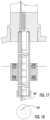
- FIG. 17is a vertical cutaway view of an alternate liquid level sensor with quality sensor.
- FIG. 18is a view of a bottom of the alternate liquid level sensor with quality sensor.
- FIG. 1shows a fire suppression system 20 .
- the systemincludes a suppressant source 22 and one or more flowpaths 24 to one or more protected locations (also known as “hazards”) 26 .
- the flowpath(s) 24pass from the source 22 to outlets 28 at the location(s) 26 .
- the exemplary outlets 28are outlets of discharge nozzles 30 for discharging discharge streams or flows 32 .
- the exemplary source 22includes multiple tanks 34 of suppressant (agent).
- the exemplary configurationis a remote driver configuration where the pressurant for each agent tank is remote of that tank.
- An exemplary agentis a liquid agent and an exemplary pressurant is nitrogen and/or argon.
- FIG. 1shows each agent tank respectively associated with a driver or pressurant tank 36 , 38 in a unit 40 , 42 , 44 , 46 .
- the agentitself is also a pressurant (e.g., inert gas systems) or the pressurant is stored in the headspace of the agent tank.
- the exemplary configurationincludes three kinds of units.
- Unit 40serves as the primary unit.
- Its driver tank 36is equipped with an electric control head 200 ( FIG. 2 ) controlled by the fire control panel 100 via a line 220 .
- an optional reserve unit, 42( FIG. 1 ) also has a driver tank with an electric control head 200 controlled by the fire control panel (via its own line 220 ).
- the suppressant source 22contains additional, secondary units 44 , 46 .
- These secondary unitsare each equipped with a pneumatic control head 202 ( FIG. 2 ) connected in-series to each other and to the primary suppression unit 40 or the reserve suppression unit 42 .
- the illustrated examplehas a series connection along a flowpath 210 from the primary unit 40 to the first secondary unit 44 and then to the second secondary unit 46 via conduits (e.g., hoses) 212 .
- the system 20may further include a reserve unit 42 which may be controlled independently of the primary and secondary units. This may be used to address re-ignition situations or situations where the primary and secondary units are insufficient to even temporarily extinguish a hazardous condition.
- the reserve unitmay itself be a primary unit having one or more associated secondary units.
- the respective suppressant tanks 34 and driver tanks 36 , 38each have a valve 50 , 52 mounted to a fitting 54 , 56 of a tank body 58 , 60 .
- a pressurant flowpath 64extends through a driver conduit 66 (e.g., hose) between the associated valves 50 , 52 .
- the flowpaths 24( FIG. 1 ) comprise respective legs 68 though conduits 70 ( FIG. 1 , e.g., hoses) from the agent tank valve 50 to a supply manifold 72 .
- Valves 74e.g., check valves
- a manifold conduit 76e.g., metal pipe
- the flowpaths 24comprise respective legs 80 though conduits 82 ( FIG. 1 , e.g., metal pipe) from the manifold conduit 76 to the locations 26
- One or more valves 90may selectively permit or block flow along the flowpath legs 80 .
- the exemplary valves 90are solenoid valves controlled by a fire control panel 100 .
- Exemplary solenoid valves 90are piloted valves piloted by a gas (e.g., nitrogen) from a pilot tank 110 having a discharge valve 112 controlled by the fire control panel.
- FIG. 1also shows a pressure switch 120 .
- the pressure switchis activated upon pressurization of the associated flowpath 80 .
- a first functionis to turn on or turn off electrical appliances that would respectively assist or impede the effectiveness of the suppression system.
- Examples of the electrical appliances 122include, but are not limited to speakers and sirens to warn occupants located in spaces 26 of imminent suppressant release, air handling units supplying and retrieving air from the spaces 26 (e.g., the switch might turn off HVAC components to limit air inflow to the affected space and keep suppressant in the space), door and window actuators (e.g., the switch might close such doors and windows to limit air introduction and suppressant loss) and related appliances (e.g., louvers).
- the pressure switch 120may also be connected to the fire control panel 100 and communicate its status information such as ready, activated or malfunction.
- FIG. 1also shows, at each location 26 , one or more sensors/detectors 130 (e.g., smoke detectors, heat detectors, and the like) and one or more pull boxes. These may be hardwired to the fire control panel.
- exemplary system activationinvolves the fire control panel receiving input (e.g., simple switched input or a digital or analog input) from a sensor/detector 130 or pull box 132 .
- the fire control panelthen activates the primary unit 40 .
- the fire control panelsends a signal (e.g., applies power via the associated line 220 ) to the primary unit 40 electric control head 200 which, in turn actuates (opens) the associated valve 52 .
- Pressurant stored in the primary unit driverpasses through the associated conduit 66 and pushes the primary unit's suppressant through the conduit 70 into the distribution piping 76 . Simultaneously, the pressure from the primary unit's driver is also transmitted through the first conduit 212 to the first secondary unit's pneumatic control head 202 . This pressure opens the first secondary unit's valve 52 causing further release of the suppressant into the distribution piping and further activation of additional secondary unit(s) via the remaining sequential conduits 212 .
- the fire control panelmay issue appropriate control signals to one or more local notification devices 214 such as speakers (for audible warnings such as alarms or prerecorded or synthesized voice warnings), other audio sources such as horns, and/or visual sources such as strobes or other lights to warn personnel in the area of a hazardous condition.
- the fire control panelmay also issue an alarm signal to a remote notification station such as monitoring center or fire station ( 800 via communications link 802 in FIG. 7 discussed below).
- the agent itselfis also a pressurant (e.g., inert gas systems) or the pressurant is stored in the headspace of the agent tank and the driver tanks are not required.
- the electronic control head(s) 200 and pneumatic control heads 202are located on the corresponding suppressant tanks.
- FIG. 3further shows one or more of the suppressant tanks and driver tanks as having a control head placement switch sensor 230 (e.g. as in WO/2017/196104), which is mounted to the tank and incorporates a switch which is depressed by the presence of a control head on the valve 52 (discharge valve assembly) ( FIG. 2 ).
- the control head placement switch sensor 230may be only on the drivers; in integrated examples it is on the suppressant tanks.
- the control head placement switch sensorsmay be mounted on the primary unit tank and the reserve unit tank, but not the secondary unit tanks.
- the exemplary switch sensorsare further connected on a common circuit loop 250 either in series or in parallel and wired to the fire control panel for supervisory monitoring of fault conditions.
- the supervisory circuit within the fire control panelinterrogates the status of the placement switch sensors by measuring circuit resistance, for example. Change in state of the placement switch sensors (for example connected to the control head or disconnected) results in, for example, change in the circuit resistance detected by the control panel.
- the panelissues the appropriate fault condition warning through its internal display upon detecting that any one of the placement switch sensors indicates loss of control head connectivity to the body of valve body 50 , 52 .
- the exemplary suppression system 20has pressure switch sensors 240 ( FIG. 3 A , e.g., diaphragm-type mechanical switch), mounted to primary, reserve and secondary tanks (either or both suppressant and driver tanks). These pressure switch sensors are further connected together on a common circuit loop 252 and wired to the control panel for supervisory monitoring.
- the supervisory circuit within the control panelinterrogates the status of the pressure switch sensors by measuring circuit resistance for example. Change in state of the pressure switch sensors (for example loss of pressure within the tank) results in, for example, change in the circuit resistance detected by the control panel.
- the panelissues the appropriate fault condition warning through its internal display 101 upon detecting that any one of the pressure switch sensors indicates change of pressure within the tanks.
- the panel 100issues warnings indicative of the disconnected control head or pressure loss within any given tank.
- further identification of the specific tank affected with disconnected control head or pressure lossin not possible. Therefore, each individual tank requires independent inspection to localize the issue and take appropriate corrective action such as re-installation of the control head or re-pressurizing of the tank. This is problematic and time consuming for large installations containing tens and hundreds of tanks.
- the fire control panel 100is schematically represented in FIG. 4 .
- a user interface driver 300supports display ( 101 above), keyboard, and related functions.
- the main processing unit 302e.g., having a microprocessor and memory/storage (e.g., solid state)
- the detection loop circuit 304receives status information from all the system input devices such as smoke sensors, heat sensors, and user pull boxes and relays this information to the processing unit.
- the control head monitor supervisory circuit 306receives status information from the control head switch sensors.
- the pressure switch sensor supervisory circuit 308receives status information from the pressure switch sensors. Both supervisory circuits relay this information to the main processing unit.
- the control circuits 310 A and 310 B( FIG. 4 ) appropriately energize control heads 200 and thus the associated valves 52 and 50 as to initiate the system response based on signals received from the main processing unit.
- the notification control circuit 312activates notification devices such as voice warnings, strobes and horns based on signals received from the main processing unit.
- the control panelmay also contain communication module 314 allowing the system status to be monitored remotely such as at a monitoring station.
- the communication module 314 interfacemay be an Ethernet connection for connection via router/modem to the Internet or may comprise a connection to a telephone landline, or may comprise a wireless telephone (e.g., cellular) connection.
- the exemplary fire control panelmay contain additional circuits and modules to receive additional input and provide additional output depending on type of installation and system complexity.
- the systemis merely one example of a baseline system to which further modifications may be made.
- An exemplary modified system discussed belowadds a parallel monitoring functionality to that already provided by the baseline.
- the exemplary modified systemmakes use of dual output sensors or switches (collectively “switches” unless indicated to the contrary) if present or provides dual output switches for parallel monitoring of a given switch.
- the modified systemmay add monitoring functions (and associated switches) not present in the baseline.
- the added functionalityis a liquid level monitoring functionality using a liquid level sensor 260 ( FIG. 3 , e.g., a magnetic float sensor) mounted to a fitting 262 on the suppressant tank.
- the added functionalityis a temperature sensing functionality using a thermistor 261 ( FIG. 3 A ) collocated with the liquid level sensor.
- FIG. 3shows the modified system as having an additional monitor module 340 (also see FIG. 6 schematic discussed below) associated with each unit 40 , 42 , 44 , 46 .
- Each monitor module 340is connected to the associated control head placement switch sensor(s) 230 , pressure switch sensor 240 , and level sensor 260 through wired connections 350 , 352 , 354 , respectively.
- the connection 250 from the control head placement sensors and the connection 252 from pressure switch sensors to the control panel 100are independent of the respective associated connections 350 and 352 to the monitor module 340 .
- each monitor module 340may include visual output devices such as a display 362 ( FIG. 6 , e.g., LCD or LED) and one or more status indicator lights 364 , 366 (e.g., colored LED).
- the displaydisplays information such as type, quantity and temperature of an agent present within the tank (e.g., “FM-200; 210 lbs.; 78 F”), while the indicator lights indicate status of the control head placement sensor and the pressure switch sensor (e.g., green light indicating connected control head and appropriately pressurized tank; red light indicating disconnected control head and inadequate pressure within the tank).
- the monitor modulemay include one or more user input devices (e.g., switches 368 , 370 and/or the display 362 being a touchscreen).
- the monitor modulemay include A/D converter 376 (e.g., chipset transforming analog voltage and current signals to digital signals), microcontroller 377 (e.g., chipset retrieving and transmitting digital signals and executing programs) and memory 378 (e.g., non-volatile memory for storing data and programs).
- A/D converter 376e.g., chipset transforming analog voltage and current signals to digital signals
- microcontroller 377e.g., chipset retrieving and transmitting digital signals and executing programs
- memory 378e.g., non-volatile memory for storing data and programs.
- analog signals transmitted via sensor connections 350 , 352 , and 354are transposed into digital signals by the A/D converter and transmitted to the microcontroller for processing.
- the microcontrollerloads, from the memory, the expected values of the sensor outputs along with the appropriate analysis program, computes response, and transmits the results to the display, indicator lights or radios.
- the monitor modulemay include battery 379
- the microcontroller 377stores in the memory 378 status information for the sensors attached to the associated suppression unit 40 , 42 , 44 , or 46 .
- Such informationmay include any combination of parameters such as: suppression unit identifying information (e.g., identification or serial number); the control head placement switch sensor 230 status (e.g., attached or disconnected); the pressure switch sensor 240 status (e.g., OK or low pressure); the agent temperature (e.g.
- a temperature sensore.g., 261
- the agent level within the tanke.g., from the liquid level sensor 260
- the computed agent masse.g., from the measured temperature and the agent level data
- the monitor module battery 379 charge levele.g., connected to other monitor module(s), connected to hand held device 400 ( FIG. 7 ), connected to gateway(s) 600 ( FIG. 11 ) or disconnected
- the monitor module connectivity statuse.g., connected to other monitor module(s), connected to hand held device 400 ( FIG. 7 ), connected to gateway(s) 600 ( FIG. 11 ) or disconnected
- the particular monitor moduleis connected (link 421 - FIG.
- the microcontrolleralso stores the status information for this second monitor module within the memory in the analogous format.
- the memory of each monitor moduleis sufficiently large to contain status information of all the suppression tank units located within a given site or particular area thereof.
- the monitor module 340offers localization of the fault condition warning at each individual unit. This offers significantly simplified system inspection for fault conditions.
- the exemplary monitor module 340is connected to electronic level sensor 260 via connection 354 ( FIGS. 3 and 3 A ).
- the sensor 260supplies data indicative of the agent quantity present within the associated suppressant tank.
- the monitor module 340 displaymay locally display the status information for any given tank including connectivity of the control head, pressure condition within the tank, and the agent quantity.
- the monitor module radiosmay provide communication: with remote sites (e.g., offsite monitoring); with other monitor modules; and/or with a user's local hand held device 400 ( FIG. 7 ) such as a mobile phone, tablet, laptop, or other portable device.
- Exemplary short range wireless communication 420 and 421may be Bluetooth via one of the radios (e.g., 372 - FIG. 6 ).
- Bluetooth mesh networkingThis provides simultaneous communication of multiple monitor modules 340 among each other and with hand held device 400 and gateway 600 .
- the hand held device 400may further communicate system status to a remote notification station 800 ( FIG. 7 ), such as monitoring center or fire station.
- Exemplary communication 422is data over the wireless carrier's network and internet (e.g., over the radio 374 ).
- One or more serversmay intervene in the communication 422 and may store relevant data about and from the system (e.g., and about and from other systems at other facilities).
- Alternative communications 422may be Ethernet or WiFi (e.g., with another radio) via router/modem (e.g., cable modem) to the internet or may comprise a connection to a telephone landline.
- the monitor modulemay thus provide local or remote monitoring and diagnosis of the suppression system 20 without connection to or other use of the fire control panel 100 . Consequently, the monitor module is not subject to requirements for re-approval/re-certification typically mandated by codes and industry standards.
- Communication between the monitor modules 340 and the hand held devicemay be direct for all monitor modules 340 or may be direct for some but indirect for others.
- the monitor modules 340may be spread far enough apart that the hand held device can't communicate with all of them from a given location (e.g., the total span exceeds Bluetooth range).
- the gaps between monitor modules 340may be small enough to allow chained communication 421 (e.g., with gaps less than Bluetooth range).
- each of the monitor modules 340may be configured to share its data via chained inter-module communication 421 with all the other modules and store such data from all the modules.
- the technician's hand held device 400may communicate 421 with just one module 340 to acquire data from all.
- Such chained communication or other inter-module communication 421has uses even where all modules 340 are within range of each other or the hand held device.
- the modules 340may be configured to normally be in a low power sleep mode and wake up to store and share data at specific times (e.g., daily at 12 am and 12 pm). The technician arriving between such times may then manually awaken one of the modules 340 (e.g., by pressing a button/switch) to then establish communication 420 between that module and the hand held device to then download to the hand held device the data from all modules 340 stored on the single awake module.
- FIGS. 8 through 10show example screens on the hand held device 400 associated with the task of inspecting an example suppression system.
- the inspecting techniciansigns into the suppression system monitoring application via a login screen (not shown).
- the app on the device 400may then (or may already automatically have) establish communication 420 with the monitors 340 .
- the exemplary appdisplays the different suppression systems pre-authorized to the technician together with their status information ( FIG. 8 ).
- the pre-authorized systemsmight comprise all systems serviced by the technician's company or may be the limited fraction of those assigned to the technician's service area or the yet more limited fraction represented by that day's route of the technician, among other possibilities.
- the appmay use text, graphics, or some combination thereof to display in a user-readable format information about system status.
- auditory alerts or visual indicatorsfor example, a sound or light on handheld device 400 , may also be used to provide an “alert”.
- a checkmark within a green circlerepresents “system normal” status
- a triangle within a yellow circlerepresents “system warning” status (e.g., sensor connectivity is intermittent, sensor battery is close to discharging, or the like)
- an exclamation mark within a red circlerepresents “supervisory fault” status (e.g., agent level too low, tank pressure too low, control head(s) disconnected, sensor battery discharged, lost sensor connectivity, or the like).
- any one of the overviewed systemsresults in displaying more detailed information ( FIG. 9 ) including status information of all the associated suppression tank units. Further selection of the particular tank unit results in displaying detailed status information pertaining to that tank unit ( FIG. 10 ) including sensor data, sensor connectivity, sensor battery level(s) and pinpoints specific fault(s) if present. Other system parameters may also be displayed such as specified (or expected) condition(s), tank unit specification (e.g. size, material, diameter, type of agent).
- FIG. 5illustrates this schematically in the context of an exemplary control head placement switch sensor 230 based on that of WO/2017/196104.
- the switch sensor 230has a body 500 having a collar portion 502 encircling an opening 504 dimensioned to receive a base portion of the control head.
- the control headmounts atop a discharge valve, the collar is mounted to a top fitting of the discharge valve.
- control headextends from the side of the valve 52 and the head placement switch sensor 230 may be positioned with the axis of its opening extending horizontally (transverse to the tank fitting and valve axis).
- a trigger 510is positioned to have a pivoting range of motion about a pivot 512 between an extended condition and a retracted or depressed condition (extended shown).
- the exemplary switch sensor 230is configured so that the trigger is depressed by the proper installation of the control head (e.g., by the placement of a swivel nut).
- the switch sensor 230further comprises a switch 520 coupled to the trigger via a plunger 522 .
- the exemplary switch 520is a stock dual output switch offering three poles: a common pole 530 ; a normally closed (NC) pole 532 ; and a normally open (NO) pole 534 connected through a wire harness 536 .
- the exemplary wire harnesshas six conductors with three conductors 540 , 541 , 542 connected to the common pole, two conductors 543 , 544 connected to the NO pole, and one conductor 546 connected to the NC pole. Alternatively, two conductors could be connected to the NC pole and one conductor to the NO pole.
- the multiple conductorsfacilitate universal installation of the sensors within the common circuit loop 250 connected to the control head monitor supervisory circuit 306 within the fire control panel.
- the sensorsmay be wired in-parallel through the common and NO poles.
- conductors 540 , 541comprise the common pole connections
- the conductors 543 , 544comprise the NO pole connections within the common circuit loop 250 .
- the supervisory circuit 306detects this short and communicates to the main processing unit 302 within the fire control panel 100 a supervisory fault condition.
- the remaining two conductors 542 , 546 within the wire harness 536may be wired to the monitor module 340 .
- the monitor moduleis configured to detect NC condition.
- the conductors 542 , 546open and the monitor module issues appropriate supervisory fault warning locally for the particular tank pair (e.g., warning light or alphanumeric indication of particular fault).
- this supervisory fault statusis also communicated to the hand held device and displayed in the monitoring application ( FIGS. 8 through 10 ).
- FIG. 11shows one alternative example of a fire suppression system 20 at a similar level to FIG. 3 .
- the systemincludes communication gateway 600 , which is used to collect, store and transmit information from monitor modules to different receivers illustrated in FIG. 12 .
- Example receiversinclude hand held device 400 and remote monitoring station 800 .
- the informationmay also be stored on a cloud storage 700 or any other suitable local or remote data server. This data server may be used to transmit suppression system information to mobile device(s) or remote monitoring station.
- the communication gatewaycontains one or more radios 602 , 604 , 606 ( FIG.
- the communication gatewaycontains one or more interfaces 608 and 610 wired via Ethernet or fiber optic cables to remote monitoring or cloud storage.
- the different radiosmay be enabled on and off by s one or more witches 612 , 614 , 616 (e.g., DIP switches under a locked cover).
- the communication gatewayalso contains microprocessor 620 to control operation of the radios and interfaces, to store suppression system status in memory 622 , and drive internal display 624 .
- the communication gatewayis preferentially externally powered (e.g., connected to AC power), but may also contain internal battery 630 connected to the power circuit 611 (e.g., having transistor or relay switches to switch between external power and battery) to allow operation during power interruption.
- FIG. 14shows exemplary suppression system information displayed by the communication gateway through its build-in display. Also shown is the status of different radios and interfaces; as above, this information may be displayed through auditory or visual signs, textually, graphically, or in a combinations of these.
- FIGS. 15 and 16show screenshots of a user interface displayed on a computer screen or a web application (e.g., at the remote monitoring location 800 ).
- the suppression system informationis displayed in a manner analogous to that shown with the mobile application in FIG. 8 - 10 .
- FIG. 15overviews the different suppression systems accessible to the technician together with their status information.
- a checkmark within a green circlerepresents “system normal” status
- an exclamation mark within a red circlerepresents “supervisory fault” status (e.g., agent level too low, tank pressure too low, control head(s) disconnected, sensor battery discharged, and/or sensor connectivity loss).
- Selecting any one of the overviewed systemsresults in displaying more detailed information ( FIG. 16 ) including status information of all the associated suppression tank units. Further selection of the particular tank unit results in displaying detailed status information pertaining to that tank unit including sensor data, sensor connectivity, and sensor battery level(s) and pinpoints specific fault(s) if present.
- cylinder 34may contain a liquid suppressant such as water.
- a liquid suppressantsuch as water.
- cylinder 36 containing the driver gasWhen activated for discharge, cylinder 36 containing the driver gas would drive water instead of clean agent through the system, and the twin-fluid mixture atomizes to form a water mist that is injected at the nozzles 30 .
- the water quality in cylinder 34may be monitored for pre-cursors to corrosion with sensors (e.g., water conductivity through capacitance, water turbidity via an LED/photodiode system) that may be integrated with the liquid level sensor 260 .
- sensorse.g., water conductivity through capacitance, water turbidity via an LED/photodiode system
- a capacitance sensor 280e.g., a capacitor where the liquid in the tank is between the two poles (shown as rods, although plates or other configurations are possible) at the lower end of a tube of the liquid level sensor.
- the exemplary liquid level sensorhas a magnetic switch array in the tube interfacing with a magnetic float (see U.S. patent applications 62/773,272 “Magnetic Trap Suppression Tank Level Sensor” and 62/773,286 “Adaptable Suppression Tank Level Sensor”, both of Piech et al. and filed Nov. 30, 2018, the disclosures of which are incorporated by reference in their entireties herein as if set forth at length.
- the exemplary sensor leadspass through the tube.
- the module 340may be pre-programmed with limit parameters on capacitance for particular agent blends.
- the particular blendmay be selected in the factory or system installation.
- the modulemay periodically compare measured capacitance to the limit parameters to assess quality and determine a fault condition if out of limit.
- the modulemay communicate the fault condition as discussed for other faults and parameters and sensors herein.
- Water flow ratesmay be monitored during the discharge via a mass flow meter 290 ( FIG. 3 A ) (e.g., a paddle wheel, turbine meter) that may be connected in the discharge port of the valve.
- Gas leakage from cylinder 36may be monitored for acoustics with a microphone 380 (e.g., embedded in monitor module 340 of FIG. 6 ). The signals from these sensors would be incorporated into the monitor module 340 as shown in FIG. 6 .
- the module 340may be pre-programmed with target flow parameters. These parameters may be determined as desired parameters when the system is tailored for a particular site and then verified by on-site testing. The test parameters may then be programmed into the module for in-use comparison. During a discharge, the module 340 compares the measured flow rate to the stored target. The module may store and communicate a fault the actual flow rates fall outside some predetermined range around the nominal target.
- the liquid quality sensor and mass flow rate informationare sent as inputs 356 , 358 alongside 350 , 352 , 354 .
- first”, “second”, and the like in the description and following claimsis for differentiation within the claim only and does not necessarily indicate relative or absolute importance or temporal order.
- identification in a claim of one element as “first” (or the like)does not preclude such “first” element from identifying an element that is referred to as “second” (or the like) in another claim or in the description.
Landscapes
- Health & Medical Sciences (AREA)
- Public Health (AREA)
- Business, Economics & Management (AREA)
- Emergency Management (AREA)
- Alarm Systems (AREA)
- Fire Alarms (AREA)
Abstract
Description
Claims (21)
Priority Applications (1)
| Application Number | Priority Date | Filing Date | Title |
|---|---|---|---|
| US17/989,966US12311212B2 (en) | 2018-11-30 | 2022-11-18 | Fire suppression system remote monitoring |
Applications Claiming Priority (4)
| Application Number | Priority Date | Filing Date | Title |
|---|---|---|---|
| US201862773450P | 2018-11-30 | 2018-11-30 | |
| PCT/US2019/051665WO2020112216A1 (en) | 2018-11-30 | 2019-09-18 | Fire suppression system remote monitoring |
| US202017252021A | 2020-12-18 | 2020-12-18 | |
| US17/989,966US12311212B2 (en) | 2018-11-30 | 2022-11-18 | Fire suppression system remote monitoring |
Related Parent Applications (2)
| Application Number | Title | Priority Date | Filing Date |
|---|---|---|---|
| US17/252,021ContinuationUS11648431B2 (en) | 2018-11-30 | 2019-09-18 | Fire suppression system remote monitoring |
| PCT/US2019/051665ContinuationWO2020112216A1 (en) | 2018-11-30 | 2019-09-18 | Fire suppression system remote monitoring |
Publications (2)
| Publication Number | Publication Date |
|---|---|
| US20230083138A1 US20230083138A1 (en) | 2023-03-16 |
| US12311212B2true US12311212B2 (en) | 2025-05-27 |
Family
ID=68084993
Family Applications (2)
| Application Number | Title | Priority Date | Filing Date |
|---|---|---|---|
| US17/252,021ActiveUS11648431B2 (en) | 2018-11-30 | 2019-09-18 | Fire suppression system remote monitoring |
| US17/989,966ActiveUS12311212B2 (en) | 2018-11-30 | 2022-11-18 | Fire suppression system remote monitoring |
Family Applications Before (1)
| Application Number | Title | Priority Date | Filing Date |
|---|---|---|---|
| US17/252,021ActiveUS11648431B2 (en) | 2018-11-30 | 2019-09-18 | Fire suppression system remote monitoring |
Country Status (4)
| Country | Link |
|---|---|
| US (2) | US11648431B2 (en) |
| EP (1) | EP3886999A1 (en) |
| CN (1) | CN112399875A (en) |
| WO (1) | WO2020112216A1 (en) |
Families Citing this family (8)
| Publication number | Priority date | Publication date | Assignee | Title |
|---|---|---|---|---|
| WO2020112223A1 (en) | 2018-11-30 | 2020-06-04 | Carrier Corporation | Fire suppression system remote monitoring |
| CN112399875A (en)* | 2018-11-30 | 2021-02-23 | 开利公司 | Fire extinguishing system remote monitoring |
| US12097395B2 (en)* | 2019-11-13 | 2024-09-24 | Kidde-Fenwal, Llc | Cartridge weight monitoring |
| FR3110141A1 (en)* | 2020-05-13 | 2021-11-19 | Airbus Operations (S.A.S.) | Aircraft comprising a propulsion unit and a propulsion unit fire-fighting system. |
| CN113450613B (en)* | 2021-05-28 | 2022-07-08 | 中国矿业大学(北京) | Device and method for simulating influence of high-temperature heat-conducting component on fire extinguishing |
| CN113694425B (en)* | 2021-08-26 | 2023-06-02 | 广东新氧器净化科技有限公司 | Fire extinguishing control bottle group mechanism, method and readable storage medium |
| GB2615114A (en)* | 2022-01-28 | 2023-08-02 | Poyntington Holdings Ltd | A self-testing fire door |
| US20250047280A1 (en)* | 2023-08-04 | 2025-02-06 | Carrier Corporation | System and method for verifying operational integrity of a control head monitor |
Citations (70)
| Publication number | Priority date | Publication date | Assignee | Title |
|---|---|---|---|---|
| US4363424A (en)* | 1980-10-23 | 1982-12-14 | Cadbury Schweppes Pcl | Quick coupling device for a gas pressurization system |
| JPH02220673A (en) | 1989-02-22 | 1990-09-03 | Toshiba Corp | Corrosion protection device for fire extinguishing system piping |
| US6598454B2 (en) | 2001-07-30 | 2003-07-29 | Bs&B Safety Systems, Inc. | System and method for monitoring a pressurized system |
| US20050056090A1 (en)* | 1996-01-23 | 2005-03-17 | Mija Industries, Inc. | Remote monitoring of fluid containers |
| US7081815B2 (en)* | 2001-08-23 | 2006-07-25 | Battelle Memorial Institute | Radio frequency security system, method for a building facility or the like, and apparatus and methods for remotely monitoring the status of fire extinguishers |
| US7126465B2 (en)* | 2003-11-17 | 2006-10-24 | Honeywell International, Inc. | Monitoring system and method |
| US7174769B2 (en)* | 1996-01-23 | 2007-02-13 | Mija Industries, Inc. | Monitoring contents of fluid containers |
| US7218237B2 (en) | 2004-05-27 | 2007-05-15 | Lawrence Kates | Method and apparatus for detecting water leaks |
| US7227450B2 (en) | 2004-03-12 | 2007-06-05 | Honeywell International, Inc. | Internet facilitated fire alarm monitoring, control system and method |
| US7360413B2 (en) | 2004-12-29 | 2008-04-22 | Water Cents, Llc | Wireless water flow monitoring and leak detection system, and method |
| US7383892B2 (en)* | 2003-09-05 | 2008-06-10 | The Viking Corporation | Preaction fire extinguishing system for ESFR cold storage applications |
| US7561057B2 (en) | 2004-05-27 | 2009-07-14 | Lawrence Kates | Method and apparatus for detecting severity of water leaks |
| US20090237239A1 (en)* | 2008-02-13 | 2009-09-24 | Mija Industries, Inc. | Emergency Equipment Power Sources |
| CN101660663A (en) | 2009-03-02 | 2010-03-03 | 徐培龙 | Water pressure remote monitoring management system of fire-fighting water supply network |
| WO2010035150A1 (en) | 2008-09-29 | 2010-04-01 | Melli Automazione S.R.L. | A monitoring device for a fire-fighting equipment |
| US7900647B2 (en) | 2004-04-05 | 2011-03-08 | Paul G Tornay | Water leak detection and prevention systems and methods |
| US7921577B2 (en) | 2006-09-12 | 2011-04-12 | Victaulic Company | Method and apparatus for drying sprinkler piping networks |
| US20110168416A1 (en) | 2010-01-12 | 2011-07-14 | David Frasure | Highly integrated data bus automatic fire extinguishing system |
| US20110308638A1 (en)* | 2010-06-16 | 2011-12-22 | Mueller International, Llc | Infrastructure monitoring devices, systems, and methods |
| US20120073839A1 (en)* | 2010-09-27 | 2012-03-29 | Thomas Iii Robert S | Actuation mechanism for a fire extinguisher |
| WO2012091721A1 (en) | 2010-12-30 | 2012-07-05 | Utc Fire & Security Corporation | Fire safety control system |
| US20120188076A1 (en)* | 2011-01-26 | 2012-07-26 | Mcsheffrey Brendan T | Fluid container resource management |
| CN102711924A (en) | 2009-12-22 | 2012-10-03 | 马里奥夫有限公司 | Method and apparatus for connecting a fire suppression system of a mobile unit to an external medium source |
| US20120255345A1 (en) | 2007-01-10 | 2012-10-11 | Tyco Fire Jproducts Lp | Methods and systems for detecting and sealing dry fit connections in a piping assembly |
| US8297370B2 (en) | 2005-06-03 | 2012-10-30 | Tyco Fire Products Lp | Releasing control unit for a residential fire protection system |
| US8350691B2 (en) | 2004-08-09 | 2013-01-08 | Siemens Industry, Inc. | Wireless building control architecture |
| US8561636B2 (en) | 2009-02-24 | 2013-10-22 | Veit Holding As | System and method for leakage control and/or testing of piping and discharge points for non-compressible fluids |
| US8573315B1 (en) | 2012-10-23 | 2013-11-05 | W. S. Darley & Co. | Self-testing and self-calibrating fire sprinkler system, method of installation and method of use |
| EP2687269A1 (en) | 2012-07-19 | 2014-01-22 | Carolina Vilas Blanco | Remote monitoring device of fire-fighting equipment |
| CN103759893A (en) | 2014-01-03 | 2014-04-30 | 重庆和航科技股份有限公司 | Method and device for monitoring leakage of fire extinguishing agent of gas fire-extinguishing system and remote monitoring system |
| US8720591B2 (en)* | 2009-10-27 | 2014-05-13 | Engineered Corrosion Solutions, Llc | Controlled discharge gas vent |
| US8720481B2 (en) | 2011-10-13 | 2014-05-13 | Kevin Duane Guy | Fluid leak detection and shutdown apparatus |
| US20140157890A1 (en)* | 2011-01-26 | 2014-06-12 | Marioff Corporation Oy | Method And Apparatus In A Medium Source Of A Fire-Fighting System |
| US8842016B1 (en) | 2011-09-06 | 2014-09-23 | Cellco Partnership | Fire extinguisher notification system and method of use |
| CN203989652U (en) | 2014-08-05 | 2014-12-10 | 保定学峰实业有限公司 | Fire hydrant pressure monitoring device |
| WO2015015227A1 (en) | 2013-08-02 | 2015-02-05 | Project Fire Products Limited | Fire suppression system |
| CN104399220A (en) | 2014-11-03 | 2015-03-11 | 浙江金盾消防器材有限公司 | Fire extinguishing system with fire extinguishing medium leakage monitoring function and fire fighting medium leakage monitoring method |
| US8981927B2 (en) | 2008-02-13 | 2015-03-17 | En-Gauge, Inc. | Object Tracking with emergency equipment |
| CN104492019A (en) | 2014-12-19 | 2015-04-08 | 乔元 | Fire-fighting pipeline water pressure monitoring equipment |
| US9033061B2 (en)* | 2009-03-23 | 2015-05-19 | Kidde Technologies, Inc. | Fire suppression system and method |
| US20150160663A1 (en) | 2013-12-11 | 2015-06-11 | Echostar Technologies, Llc | Detection and mitigation of water leaks with home automation |
| US9095736B2 (en)* | 2013-05-07 | 2015-08-04 | Engineered Corrosion Solutions, Llc | Corrosion monitoring in a fire sprinkler system |
| CN104826262A (en) | 2015-06-09 | 2015-08-12 | 张维秀 | Fire-fighting apparatus monitoring method, fire-fighting apparatus monitoring device and fire-fighting apparatus monitoring system |
| US9144700B2 (en)* | 2008-09-15 | 2015-09-29 | Engineered Corrosion Solutions, Llc | Fire protection systems having reduced corrosion |
| US20150297925A1 (en) | 2012-11-30 | 2015-10-22 | Marioff Corporation Oy | Intelligent sprinkler system section valve |
| US20160096053A1 (en) | 2014-10-07 | 2016-04-07 | Akron Brass Company | Fire suppression system component integration |
| US9383289B1 (en)* | 2011-07-05 | 2016-07-05 | John Meyer | Water leak detection system |
| US20160263410A1 (en)* | 2010-12-30 | 2016-09-15 | William Armand Enk, SR. | Fire suppression system |
| US9463344B2 (en)* | 2014-04-29 | 2016-10-11 | Kidde Technologies, Inc. | Bellows actuated temperature compensated pressure switching apparatus and system |
| WO2016196104A1 (en) | 2015-06-04 | 2016-12-08 | Utc Fire & Security Corporation | Externally mounted device for the supervision of a fire suppression system |
| WO2016200608A1 (en) | 2015-06-08 | 2016-12-15 | Utc Fire & Security Corporation | Internally mounted device for the supervision of a fire suppression system |
| US9541625B2 (en) | 2011-08-25 | 2017-01-10 | En-Gauge, Inc. | Emergency resource location and status |
| US20170014655A1 (en) | 2015-07-17 | 2017-01-19 | Kidde Graviner Limited | Aircraft with fire suppression control system |
| US9619996B1 (en)* | 2014-08-14 | 2017-04-11 | Kyle B. Smith | Distributed wild fire alert system |
| US20170100617A1 (en)* | 2014-03-07 | 2017-04-13 | Engineered Corrosion Solutions, Llc | Devices, methods and systems for monitoring water-based fire sprinkler systems |
| KR20170043205A (en) | 2015-10-13 | 2017-04-21 | 주식회사 진화이앤씨 | Pressure container leakage monitoring system of fire-fighting equipment |
| US20170209725A1 (en)* | 2016-01-22 | 2017-07-27 | Nec Laboratories America, Inc. | Apparatus, methods, and systems for monitoring fire extinguisher operational readiness |
| WO2018112385A2 (en) | 2016-12-16 | 2018-06-21 | Tyco Fire Products Lp | Systems and methods for mechanical fire suppression, monitoring and analytics |
| US20180169451A1 (en)* | 2016-12-16 | 2018-06-21 | Tyco Fire Products Lp | Monitoring Platform for Mechanical Fire Suppression Systems |
| US10213635B2 (en)* | 2016-09-22 | 2019-02-26 | Kidde Technologies, Inc. | Bracket interlock systems |
| US20190209880A1 (en)* | 2018-01-05 | 2019-07-11 | Fireboy-Xintex Llc | Dynamic fire suppression system and method thereof |
| US20190224512A1 (en)* | 2018-01-23 | 2019-07-25 | Tyco Fire Products Lp | Systems and methods of monitoring temperature in a fire suppression system |
| US20190224509A1 (en)* | 2018-01-23 | 2019-07-25 | Tyco Fire Products Lp | System and method for monitoring and controlling a fire suppression system |
| US20190374803A1 (en)* | 2018-06-08 | 2019-12-12 | Tyco Fire Products Lp | Cartridge monitoring system |
| US20200097904A1 (en)* | 2018-09-22 | 2020-03-26 | Fedex Corporate Services, Inc. | Dynamically transitioning system for monitoring a shipping container for an environmental anomaly related to the shipping container |
| US20200197735A1 (en)* | 2017-05-03 | 2020-06-25 | Kino Offshore Engineering Co., Limited | Automatic security bottle system and automatic control method therefor |
| US20210268322A1 (en)* | 2020-03-02 | 2021-09-02 | South-Tek Systems, LLC | Dry Pipe Fire Protection System Air Maintenance Device with Pressure Monitor |
| US20210283446A1 (en)* | 2018-11-30 | 2021-09-16 | Carrier Corporation | Fire Suppression System Remote Monitoring |
| US20210364335A1 (en)* | 2018-11-30 | 2021-11-25 | Carrier Corporation | Suppression Tank Scale and Level Determination |
| US20210361991A1 (en)* | 2018-11-30 | 2021-11-25 | Carrier Corporation | Fire Suppression System Remote Monitoring |
- 2019
- 2019-09-18CNCN201980041195.5Apatent/CN112399875A/enactivePending
- 2019-09-18USUS17/252,021patent/US11648431B2/enactiveActive
- 2019-09-18WOPCT/US2019/051665patent/WO2020112216A1/ennot_activeCeased
- 2019-09-18EPEP19779699.8Apatent/EP3886999A1/enactivePending
- 2022
- 2022-11-18USUS17/989,966patent/US12311212B2/enactiveActive
Patent Citations (79)
| Publication number | Priority date | Publication date | Assignee | Title |
|---|---|---|---|---|
| US4363424A (en)* | 1980-10-23 | 1982-12-14 | Cadbury Schweppes Pcl | Quick coupling device for a gas pressurization system |
| JPH02220673A (en) | 1989-02-22 | 1990-09-03 | Toshiba Corp | Corrosion protection device for fire extinguishing system piping |
| US20050056090A1 (en)* | 1996-01-23 | 2005-03-17 | Mija Industries, Inc. | Remote monitoring of fluid containers |
| US7174769B2 (en)* | 1996-01-23 | 2007-02-13 | Mija Industries, Inc. | Monitoring contents of fluid containers |
| US6598454B2 (en) | 2001-07-30 | 2003-07-29 | Bs&B Safety Systems, Inc. | System and method for monitoring a pressurized system |
| US7081815B2 (en)* | 2001-08-23 | 2006-07-25 | Battelle Memorial Institute | Radio frequency security system, method for a building facility or the like, and apparatus and methods for remotely monitoring the status of fire extinguishers |
| US7383892B2 (en)* | 2003-09-05 | 2008-06-10 | The Viking Corporation | Preaction fire extinguishing system for ESFR cold storage applications |
| US7126465B2 (en)* | 2003-11-17 | 2006-10-24 | Honeywell International, Inc. | Monitoring system and method |
| US7227450B2 (en) | 2004-03-12 | 2007-06-05 | Honeywell International, Inc. | Internet facilitated fire alarm monitoring, control system and method |
| US7900647B2 (en) | 2004-04-05 | 2011-03-08 | Paul G Tornay | Water leak detection and prevention systems and methods |
| US7218237B2 (en) | 2004-05-27 | 2007-05-15 | Lawrence Kates | Method and apparatus for detecting water leaks |
| US7561057B2 (en) | 2004-05-27 | 2009-07-14 | Lawrence Kates | Method and apparatus for detecting severity of water leaks |
| US8350691B2 (en) | 2004-08-09 | 2013-01-08 | Siemens Industry, Inc. | Wireless building control architecture |
| US7360413B2 (en) | 2004-12-29 | 2008-04-22 | Water Cents, Llc | Wireless water flow monitoring and leak detection system, and method |
| US8297370B2 (en) | 2005-06-03 | 2012-10-30 | Tyco Fire Products Lp | Releasing control unit for a residential fire protection system |
| US7921577B2 (en) | 2006-09-12 | 2011-04-12 | Victaulic Company | Method and apparatus for drying sprinkler piping networks |
| US20120255345A1 (en) | 2007-01-10 | 2012-10-11 | Tyco Fire Jproducts Lp | Methods and systems for detecting and sealing dry fit connections in a piping assembly |
| US20090237239A1 (en)* | 2008-02-13 | 2009-09-24 | Mija Industries, Inc. | Emergency Equipment Power Sources |
| US8981927B2 (en) | 2008-02-13 | 2015-03-17 | En-Gauge, Inc. | Object Tracking with emergency equipment |
| US8749373B2 (en)* | 2008-02-13 | 2014-06-10 | En-Gauge, Inc. | Emergency equipment power sources |
| US9144700B2 (en)* | 2008-09-15 | 2015-09-29 | Engineered Corrosion Solutions, Llc | Fire protection systems having reduced corrosion |
| WO2010035150A1 (en) | 2008-09-29 | 2010-04-01 | Melli Automazione S.R.L. | A monitoring device for a fire-fighting equipment |
| US8561636B2 (en) | 2009-02-24 | 2013-10-22 | Veit Holding As | System and method for leakage control and/or testing of piping and discharge points for non-compressible fluids |
| CN101660663A (en) | 2009-03-02 | 2010-03-03 | 徐培龙 | Water pressure remote monitoring management system of fire-fighting water supply network |
| US9033061B2 (en)* | 2009-03-23 | 2015-05-19 | Kidde Technologies, Inc. | Fire suppression system and method |
| US8720591B2 (en)* | 2009-10-27 | 2014-05-13 | Engineered Corrosion Solutions, Llc | Controlled discharge gas vent |
| CN102711924A (en) | 2009-12-22 | 2012-10-03 | 马里奥夫有限公司 | Method and apparatus for connecting a fire suppression system of a mobile unit to an external medium source |
| US20120317780A1 (en) | 2009-12-22 | 2012-12-20 | Marioff Corporation Oy | Method and apparatus for connecting the fire extinguishing system of a mobile unit to an external medium source |
| US20110168416A1 (en) | 2010-01-12 | 2011-07-14 | David Frasure | Highly integrated data bus automatic fire extinguishing system |
| CN102125741A (en) | 2010-01-12 | 2011-07-20 | 基德科技公司 | Highly integrated data bus automatic fire extinguishing system |
| US20110308638A1 (en)* | 2010-06-16 | 2011-12-22 | Mueller International, Llc | Infrastructure monitoring devices, systems, and methods |
| US20120073839A1 (en)* | 2010-09-27 | 2012-03-29 | Thomas Iii Robert S | Actuation mechanism for a fire extinguisher |
| US20160263410A1 (en)* | 2010-12-30 | 2016-09-15 | William Armand Enk, SR. | Fire suppression system |
| CN103354759A (en) | 2010-12-30 | 2013-10-16 | Utc消防及保安公司 | Fire safety control system |
| WO2012091721A1 (en) | 2010-12-30 | 2012-07-05 | Utc Fire & Security Corporation | Fire safety control system |
| US20150041158A1 (en)* | 2010-12-30 | 2015-02-12 | Utc Fire And Security Corporation | Fire safety control system |
| US20120188076A1 (en)* | 2011-01-26 | 2012-07-26 | Mcsheffrey Brendan T | Fluid container resource management |
| US20140157890A1 (en)* | 2011-01-26 | 2014-06-12 | Marioff Corporation Oy | Method And Apparatus In A Medium Source Of A Fire-Fighting System |
| US9383289B1 (en)* | 2011-07-05 | 2016-07-05 | John Meyer | Water leak detection system |
| US9541625B2 (en) | 2011-08-25 | 2017-01-10 | En-Gauge, Inc. | Emergency resource location and status |
| US8842016B1 (en) | 2011-09-06 | 2014-09-23 | Cellco Partnership | Fire extinguisher notification system and method of use |
| US8720481B2 (en) | 2011-10-13 | 2014-05-13 | Kevin Duane Guy | Fluid leak detection and shutdown apparatus |
| EP2687269A1 (en) | 2012-07-19 | 2014-01-22 | Carolina Vilas Blanco | Remote monitoring device of fire-fighting equipment |
| US8573315B1 (en) | 2012-10-23 | 2013-11-05 | W. S. Darley & Co. | Self-testing and self-calibrating fire sprinkler system, method of installation and method of use |
| CN105025988A (en) | 2012-11-30 | 2015-11-04 | 马里奥夫有限公司 | Smart sprinkler system section valve |
| US20150297925A1 (en) | 2012-11-30 | 2015-10-22 | Marioff Corporation Oy | Intelligent sprinkler system section valve |
| US9095736B2 (en)* | 2013-05-07 | 2015-08-04 | Engineered Corrosion Solutions, Llc | Corrosion monitoring in a fire sprinkler system |
| WO2015015227A1 (en) | 2013-08-02 | 2015-02-05 | Project Fire Products Limited | Fire suppression system |
| US20150160663A1 (en) | 2013-12-11 | 2015-06-11 | Echostar Technologies, Llc | Detection and mitigation of water leaks with home automation |
| CN103759893A (en) | 2014-01-03 | 2014-04-30 | 重庆和航科技股份有限公司 | Method and device for monitoring leakage of fire extinguishing agent of gas fire-extinguishing system and remote monitoring system |
| US20170100617A1 (en)* | 2014-03-07 | 2017-04-13 | Engineered Corrosion Solutions, Llc | Devices, methods and systems for monitoring water-based fire sprinkler systems |
| US9463344B2 (en)* | 2014-04-29 | 2016-10-11 | Kidde Technologies, Inc. | Bellows actuated temperature compensated pressure switching apparatus and system |
| CN203989652U (en) | 2014-08-05 | 2014-12-10 | 保定学峰实业有限公司 | Fire hydrant pressure monitoring device |
| US9619996B1 (en)* | 2014-08-14 | 2017-04-11 | Kyle B. Smith | Distributed wild fire alert system |
| TW201714639A (en) | 2014-10-07 | 2017-05-01 | 阿克隆黃銅公司 | Fire suppression system component integration |
| US20160096053A1 (en) | 2014-10-07 | 2016-04-07 | Akron Brass Company | Fire suppression system component integration |
| CN104399220A (en) | 2014-11-03 | 2015-03-11 | 浙江金盾消防器材有限公司 | Fire extinguishing system with fire extinguishing medium leakage monitoring function and fire fighting medium leakage monitoring method |
| CN104492019A (en) | 2014-12-19 | 2015-04-08 | 乔元 | Fire-fighting pipeline water pressure monitoring equipment |
| WO2016196104A1 (en) | 2015-06-04 | 2016-12-08 | Utc Fire & Security Corporation | Externally mounted device for the supervision of a fire suppression system |
| CN108064183A (en) | 2015-06-04 | 2018-05-22 | Utc 消防及保安公司 | Externally installed equipment for monitoring fire suppression systems |
| WO2016200608A1 (en) | 2015-06-08 | 2016-12-15 | Utc Fire & Security Corporation | Internally mounted device for the supervision of a fire suppression system |
| CN104826262A (en) | 2015-06-09 | 2015-08-12 | 张维秀 | Fire-fighting apparatus monitoring method, fire-fighting apparatus monitoring device and fire-fighting apparatus monitoring system |
| US20170014655A1 (en) | 2015-07-17 | 2017-01-19 | Kidde Graviner Limited | Aircraft with fire suppression control system |
| CN106345089A (en) | 2015-07-17 | 2017-01-25 | 基德格莱维诺有限公司 | Aircraft with fire suppression control system |
| KR20170043205A (en) | 2015-10-13 | 2017-04-21 | 주식회사 진화이앤씨 | Pressure container leakage monitoring system of fire-fighting equipment |
| US20170209725A1 (en)* | 2016-01-22 | 2017-07-27 | Nec Laboratories America, Inc. | Apparatus, methods, and systems for monitoring fire extinguisher operational readiness |
| US10213635B2 (en)* | 2016-09-22 | 2019-02-26 | Kidde Technologies, Inc. | Bracket interlock systems |
| WO2018112385A2 (en) | 2016-12-16 | 2018-06-21 | Tyco Fire Products Lp | Systems and methods for mechanical fire suppression, monitoring and analytics |
| US20180169451A1 (en)* | 2016-12-16 | 2018-06-21 | Tyco Fire Products Lp | Monitoring Platform for Mechanical Fire Suppression Systems |
| US20200197735A1 (en)* | 2017-05-03 | 2020-06-25 | Kino Offshore Engineering Co., Limited | Automatic security bottle system and automatic control method therefor |
| US20190209880A1 (en)* | 2018-01-05 | 2019-07-11 | Fireboy-Xintex Llc | Dynamic fire suppression system and method thereof |
| US20190224512A1 (en)* | 2018-01-23 | 2019-07-25 | Tyco Fire Products Lp | Systems and methods of monitoring temperature in a fire suppression system |
| US20190224509A1 (en)* | 2018-01-23 | 2019-07-25 | Tyco Fire Products Lp | System and method for monitoring and controlling a fire suppression system |
| US20190374803A1 (en)* | 2018-06-08 | 2019-12-12 | Tyco Fire Products Lp | Cartridge monitoring system |
| US20200097904A1 (en)* | 2018-09-22 | 2020-03-26 | Fedex Corporate Services, Inc. | Dynamically transitioning system for monitoring a shipping container for an environmental anomaly related to the shipping container |
| US20210283446A1 (en)* | 2018-11-30 | 2021-09-16 | Carrier Corporation | Fire Suppression System Remote Monitoring |
| US20210364335A1 (en)* | 2018-11-30 | 2021-11-25 | Carrier Corporation | Suppression Tank Scale and Level Determination |
| US20210361991A1 (en)* | 2018-11-30 | 2021-11-25 | Carrier Corporation | Fire Suppression System Remote Monitoring |
| US20210268322A1 (en)* | 2020-03-02 | 2021-09-02 | South-Tek Systems, LLC | Dry Pipe Fire Protection System Air Maintenance Device with Pressure Monitor |
Non-Patent Citations (6)
| Title |
|---|
| Chinese Office Action dated Apr. 1, 2022 for Chinese Patent Application No. 201980041195.5. |
| Chinese Office Action dated Oct. 14, 2022 for Chinese Patent Application No. 201980041195.5. |
| European Office Action dated Nov. 7, 2023 for European Patent Application No. 19779699.8. |
| International Search Report and Written Opinion dated Nov. 28, 2019 for PCT/US2019/051665. |
| Notice of Allowance dated Aug. 24, 2022 for U.S. Appl. No. 17/252,021. |
| US Office Action dated May 5, 2022 for U.S. Appl. No. 17/252,021. |
Also Published As
| Publication number | Publication date |
|---|---|
| US20230083138A1 (en) | 2023-03-16 |
| CN112399875A (en) | 2021-02-23 |
| WO2020112216A1 (en) | 2020-06-04 |
| US11648431B2 (en) | 2023-05-16 |
| EP3886999A1 (en) | 2021-10-06 |
| US20210283446A1 (en) | 2021-09-16 |
Similar Documents
| Publication | Publication Date | Title |
|---|---|---|
| US12311212B2 (en) | Fire suppression system remote monitoring | |
| EP2658616B1 (en) | Fire safety control system | |
| US12296213B2 (en) | Fire suppression system remote monitoring | |
| US20220212046A1 (en) | Fire detection system with multiple stage alarms | |
| JP2018500991A (en) | Fire extinguishing devices, especially alarm valve stations for sprinklers or water jet fire extinguishing devices, and fire extinguishing devices | |
| US11735024B2 (en) | Gas monitoring and alarm systems and methods | |
| US20220249892A1 (en) | Fire detection system with a learning mode | |
| KR20160010896A (en) | Smart fire-fighting management system for cultural assets and method thereof | |
| KR200493371Y1 (en) | Smoke control system for living room | |
| KR102008618B1 (en) | Line resistance meter of fire-prevention facilities | |
| US20240029537A1 (en) | Gas monitoring and alarm systems and methods including level indicator unit | |
| CN114984503B (en) | Multi-parameter fire-fighting monitoring equipment based on data analysis | |
| KR102873671B1 (en) | Fire detection system with learning mode | |
| KR200429451Y1 (en) | P type composite receiver for fire management | |
| NO347284B1 (en) | Automatic testing, inspection, surveillance, and maintainance system of water-based systems | |
| HK1190353B (en) | Fire safety control system |
Legal Events
| Date | Code | Title | Description |
|---|---|---|---|
| FEPP | Fee payment procedure | Free format text:ENTITY STATUS SET TO UNDISCOUNTED (ORIGINAL EVENT CODE: BIG.); ENTITY STATUS OF PATENT OWNER: LARGE ENTITY | |
| STPP | Information on status: patent application and granting procedure in general | Free format text:DOCKETED NEW CASE - READY FOR EXAMINATION | |
| STPP | Information on status: patent application and granting procedure in general | Free format text:NON FINAL ACTION MAILED | |
| STPP | Information on status: patent application and granting procedure in general | Free format text:RESPONSE TO NON-FINAL OFFICE ACTION ENTERED AND FORWARDED TO EXAMINER | |
| STPP | Information on status: patent application and granting procedure in general | Free format text:FINAL REJECTION MAILED | |
| STPP | Information on status: patent application and granting procedure in general | Free format text:DOCKETED NEW CASE - READY FOR EXAMINATION | |
| STPP | Information on status: patent application and granting procedure in general | Free format text:NOTICE OF ALLOWANCE MAILED -- APPLICATION RECEIVED IN OFFICE OF PUBLICATIONS | |
| STPP | Information on status: patent application and granting procedure in general | Free format text:AWAITING TC RESP., ISSUE FEE NOT PAID | |
| STPP | Information on status: patent application and granting procedure in general | Free format text:NOTICE OF ALLOWANCE MAILED -- APPLICATION RECEIVED IN OFFICE OF PUBLICATIONS | |
| AS | Assignment | Owner name:CARRIER CORPORATION, FLORIDA Free format text:ASSIGNMENT OF ASSIGNORS INTEREST;ASSIGNORS:PIECH, MARCIN;CORN, MAY L.;CIOL, JOSEPH WILLIAM;AND OTHERS;SIGNING DATES FROM 20181218 TO 20190128;REEL/FRAME:071057/0680 | |
| AS | Assignment | Owner name:KIDDE-FENWAL, LLC, MASSACHUSETTS Free format text:ASSIGNMENT OF ASSIGNORS INTEREST;ASSIGNOR:CARRIER CORPORATION;REEL/FRAME:070959/0591 Effective date:20250421 | |
| STCF | Information on status: patent grant | Free format text:PATENTED CASE | |
| AS | Assignment | Owner name:MGG INVESTMENT GROUP LP, AS COLLATERAL AGENT, NEW YORK Free format text:SECURITY INTEREST;ASSIGNOR:KIDDE-FENWAL, LLC;REEL/FRAME:072039/0358 Effective date:20250717 |