US12310901B2 - Coupling systems for releasably coupling equipment to a patient transport systems - Google Patents
Coupling systems for releasably coupling equipment to a patient transport systemsDownload PDFInfo
- Publication number
- US12310901B2 US12310901B2US17/802,299US202117802299AUS12310901B2US 12310901 B2US12310901 B2US 12310901B2US 202117802299 AUS202117802299 AUS 202117802299AUS 12310901 B2US12310901 B2US 12310901B2
- Authority
- US
- United States
- Prior art keywords
- base member
- equipment
- retractable stop
- release
- stop member
- Prior art date
- Legal status (The legal status is an assumption and is not a legal conclusion. Google has not performed a legal analysis and makes no representation as to the accuracy of the status listed.)
- Active
Links
Images


Classifications
- A—HUMAN NECESSITIES
- A61—MEDICAL OR VETERINARY SCIENCE; HYGIENE
- A61G—TRANSPORT, PERSONAL CONVEYANCES, OR ACCOMMODATION SPECIALLY ADAPTED FOR PATIENTS OR DISABLED PERSONS; OPERATING TABLES OR CHAIRS; CHAIRS FOR DENTISTRY; FUNERAL DEVICES
- A61G5/00—Chairs or personal conveyances specially adapted for patients or disabled persons, e.g. wheelchairs
- A61G5/10—Parts, details or accessories
- A—HUMAN NECESSITIES
- A61—MEDICAL OR VETERINARY SCIENCE; HYGIENE
- A61G—TRANSPORT, PERSONAL CONVEYANCES, OR ACCOMMODATION SPECIALLY ADAPTED FOR PATIENTS OR DISABLED PERSONS; OPERATING TABLES OR CHAIRS; CHAIRS FOR DENTISTRY; FUNERAL DEVICES
- A61G7/00—Beds specially adapted for nursing; Devices for lifting patients or disabled persons
- A61G7/05—Parts, details or accessories of beds
- A—HUMAN NECESSITIES
- A61—MEDICAL OR VETERINARY SCIENCE; HYGIENE
- A61G—TRANSPORT, PERSONAL CONVEYANCES, OR ACCOMMODATION SPECIALLY ADAPTED FOR PATIENTS OR DISABLED PERSONS; OPERATING TABLES OR CHAIRS; CHAIRS FOR DENTISTRY; FUNERAL DEVICES
- A61G1/00—Stretchers
- A61G1/04—Parts, details or accessories, e.g. head-, foot-, or like rests specially adapted for stretchers
- A—HUMAN NECESSITIES
- A61—MEDICAL OR VETERINARY SCIENCE; HYGIENE
- A61G—TRANSPORT, PERSONAL CONVEYANCES, OR ACCOMMODATION SPECIALLY ADAPTED FOR PATIENTS OR DISABLED PERSONS; OPERATING TABLES OR CHAIRS; CHAIRS FOR DENTISTRY; FUNERAL DEVICES
- A61G2203/00—General characteristics of devices
- A61G2203/70—General characteristics of devices with special adaptations, e.g. for safety or comfort
- A61G2203/80—General characteristics of devices with special adaptations, e.g. for safety or comfort for connecting a trolley to a device, e.g. bed or column table
Definitions
- the present disclosurerelates to coupling systems for releasably coupling equipment to a patient transport system, such as, but not limited to coupling medical equipment to personal transportation systems such as stretchers, wheelchairs or portable beds.
- Patient transportation systemsinclude, for example, stretchers, wheelchairs and portable beds. Oftentimes, along with transporting the patient, there is often a need to transport equipment associated with the patient.
- a coupling systemfor releasably coupling equipment to a patient transport system
- the coupling systemcomprising: a base member connectable to the patient transport system, and a positioning member connectable to the equipment, the positioning member arranged to be releasably coupled to the base member;
- the base membercomprising: a recessed portion for receiving an end portion of the positioning member, the recessed portion having a base with an opening defined therein; and a retractable stop member in the recessed portion and moveable between: an extended position in which the retractable stop member extends into the recessed portion through the opening, and a recessed position in which the retractable stop member is retracted from the recessed portion through the opening, the retractable stop member being resiliently biased to the extended position;
- the positioning membercomprising: an end portion sized and shaped to be received in the recessed portion of the positioning member and to engage with the retractable stop member when the positioning member is positioned in the recessed portion.
- the coupling systemfurther comprises an actuation system for actuating the retractable stop member between the extended position and the retracted position.
- the actuation systemcomprises an actuator for moving the retractable stop member to the retracted position from the extended position, and a resilient member for resiliently biasing the retractable stop member towards the extended position.
- the actuatoris a handle connected to the retractable stop member by at least one pin, optionally two pins, and the resilient member is a spring.
- the base memberhas a three part configuration, (i) an upper portion; (ii) a lower portion connected to the upper portion, and (iii) a retractable stop member portion, including the retractable stop member, moveably arranged between the upper portion and the lower portion.
- the upper portioncomprises an upper body having the recessed portion defined therein;
- the lower portioncomprises a lower body having an upper face, the upper face being adapted to moveably house the retractable stop member portion in a recess;
- the retractable stop member portioncomprises a plate portion, sized and shaped to be received in the recess of the upper face of the lower body, and the retractable stop member extending upwardly from the plate portion.
- the plate portion of the retractable stop member portioncomprises an opening for movingly receiving the pin.
- the recessed portionis defined by a wall extending circumferentially around the base, there being provided an open access area without the wall through which the positioning member can be inserted and removed.
- the recessed portionhas a plurality of sides, and the wall extends along all but one of the plurality of sides which is the open access end.
- the retractable stop memberhas a wedge configuration having a decreasing height towards the open access end.
- the coupling systemfurther comprises a clamp for attaching the base member to the patient transport system.
- the clampmay be attachable to a portion of the base member with a fastener.
- the clampis formed by upper and lower portions of the base member.
- oppositely facing sides of the upper and lower portionsdefine the clamp configured to close around a circumference of the frame of the patient transport system when the upper and lower portions of the base member are brought closer together.
- the coupling systemfurther comprises at least one arm extending from the base member, the at least one arm attachable to the patient transport system or being integral with the patient transport system.
- the positioning member end portioncomprises an opening for receiving the retractable stop member when the retractable stop member is in the extended position.
- the coupling systemfurther comprises an equipment frame to which the positioning member is attached or attachable, the equipment frame also being adapted to attach the equipment thereto.
- the equipment frameis also configured to be attachable to the patient transport system, such as a frame of a stretcher, for example.
- the equipment frameis attachable to the frame of the patient transport system by at least one guide member.
- the at least one guide membermay be detachably attachable to the frame, such as by clamping or fasteners.
- the at least one guide memberis attached to the frame of the patient transport system, the positioning member is attached to an equipment frame which is removably engaged with the at least one guide member.
- the equipment framemay comprise two arms, each arm being configured to be received in a pair of guide members which are axially aligned and attached to the frame along one side of a stretcher.
- the at least one guide membercomprises a first opening for receiving the frame of the patient transport system, and a second opening for receiving an arm of the equipment frame.
- the at least one guide membermay comprise two parts connectable together by one or more fasteners, the first opening being defined by the two parts.
- the second openingmay be formed within a guide member body of the guide member.
- the equipment frameincludes at least one base member of a connecting device, the at least one base member of the connecting device being attachable, or being attached, to the equipment.
- the equipment framecomprises a cross-bar to which the base member is attached.
- the equipment framecomprises at least one horizontal arm extending substantially transversely to the cross-bar and engageable with the at least one guide member on the patient transport system.
- the equipment framecomprises at least one vertical arm extending from the cross-bar.
- the equipment framecomprises at least one support surface for supporting medical equipment.
- the connecting devicecomprises a base member (which can also be referred to herein as a connecting device base member) connectable to the equipment frame, and a release member connectable to the equipment, the base member and the release member being releasably connectable together in a coupled position.
- the coupled positioncan be locked in certain embodiments.
- the base membermay have a front face including a contact portion for contacting a contact face of the release member.
- the release membermay comprise a body which is configured to be received in a pocket on the front face of the base member, when the base member and the release member are in the coupled position, the pocket having an open access end through which the release member can be slidingly inserted and removed from the pocket.
- the base membermay include a stop member moveable, by an actuator, between a lock position in which the stop member interengages with the release member to prevent removal of the release member from the pocket of the base member, and a release position in which the release member can be separated from the base member.
- the base memberhas a shoulder extending around the contact portion to define the pocket for receiving the release member, the shoulder engageable with a portion of a flange of the release member when the release member is positioned on the base member.
- the stop memberis positioned in a recess within the contact portion and moveable by the actuator which is connected to a resilient lock mechanism between the lock position in which at least a portion of the stop member extends from the recess and abuts an edge of an opening defined in the release member contact face in the coupled position, and a release position in which the stop member is retracted into the recess.
- the stop membermay have a wedge shaped portion with a thinner end of the wedge facing the open access end of the pocket, and wherein the resilient lock mechanism is configured to permit the stop member to move into the recess as the release member is slid into the pocket.
- the actuatormay have a neutral position and a deployed position, wherein when the actuator is in the neutral position, the stop member is resiliently biased towards the lock position.
- a perimeter of the body of the release memberis circular in shape, such that the release member can be rotated within the pocket in one or both of the lock position and the release position when the base member is coupled to the release member.
- the stop membermay function as a rotation point and is positioned substantially centrally of the contact portion of the base member.
- a perimeter of the body of the release memberhas an eccentric shape such that the release member is not rotatable in the pocket of the base member when the base member is coupled to the release member.
- the shoulderis configured to delimit movement of the release member orthogonally away from the front face of the base member, when the base member and the release member are in the coupled position.
- the connecting devicecomprises a base member (which can also be referred to herein as a connecting device base member) connectable to the equipment frame, and a release member connectable to the equipment, the base member and the release member being releasably connectable together in a coupled position.
- a base memberwhich can also be referred to herein as a connecting device base member
- a release memberconnectable to the equipment, the base member and the release member being releasably connectable together in a coupled position.
- the release membercomprises a plate-like body with a first side, the first side defining a planar contact face, and a second side having a collar extending therefrom, the collar positioned inwardly of a perimeter of the release member to define a flange portion;
- the base memberhaving: a front face including a planar contact portion for contacting the contact face of the release member; a shoulder extending around a portion of a periphery of the planar portion to define a pocket for receiving the release member, the shoulder engageable with a portion of the flange of the release member when the release member is positioned on the base member; an open access end through which the release member can be slidingly inserted and removed from the pocket; a stop member positioned in a recess within the planar contact portion and moveable by a resilient lock mechanism and an actuator between a lock position in which at least a portion of the stop member extends from the recess and abuts an edge of an opening defined in the release member contact face in the coupled position, and
- the base membercomprises a plurality of spring loaded ball bearings partially extending from recesses formed in the front face of the base member and engageable with corresponding recesses defined in the planar contact face of the release member.
- the planar contact face of the release memberhas an anti-friction layer.
- the coupling systemfurther comprises a damping member attachable to a back face of the base member and arranged to be positioned between the base portion and the surface in use, the damping member being arranged to absorb vibration and/or shock.
- the coupling systemfurther comprises a top plate attachable to the collar of the release member and attachable to the equipment.
- the perimeter of the plate-like body of the release memberis circular in shape
- the stop member of the base memberis positioned substantially centrally of the planar contact portion
- the opening of the release memberis positioned substantially centrally of the plate-like body, such that the release member can be rotated within the pocket when the stop member is in the lock position.
- the perimeter of the plate-like body of the release memberhas an eccentric shape such that the release member is not rotatable in the pocket of the base member.
- a patient transport systemcomprising a frame having a patient support surface attached thereto, the frame including the base member and optionally the positioning member of the coupling system.
- the patient transport systemfurther includes a supporting rail assembly connected to the frame of the patient transport system by at least one guide member.
- the supporting rail assemblymay include a support rail connected to the at least one guide member and at least one support cross member connected to the support rail.
- the supporting rail assemblymay also be connected to the base member of the coupling system.
- a patient transport systemcomprising a frame having a patient support surface attached thereto, and a supporting rail assembly connected to the frame of the patient transport system by at least one guide member.
- the supporting rail assemblymay include a support rail connected to the at least one guide member and at least one support cross member connected to the support rail.
- the patient transport systemmay further comprise the base member connected to the frame of the patient transport system, and optionally the positioning member also connected to the frame of the patient transport system.
- the patient support surfaceis a mattress of a stretcher.
- a stretchercomprising a frame having a patient support surface attached thereto, the frame including the base member of the coupling system as described above.
- an equipment framefor connecting equipment to a patient transport system, the equipment frame comprising at least one support surface for supporting the equipment, and a positioning member of the coupling system as described above.
- the positioning member or the equipment frame supporting the positioning memberfurther comprises at least one connecting device attached to the equipment frame, the at least one connecting device configured to be releasably attached to the equipment.
- the positioning member or the equipment frame supporting the positioning memberfurther comprises at least one base member of a connecting device attached to the equipment frame, the at least one connecting device base member releasably attachable to a release member of the connecting device in a coupled position, and the connecting device release member being attachable to the equipment.
- the patient transport systemis a personal transport system such as a stretcher.
- the stretchermay be for use in aircrafts, or for adapted ground use.
- the equipmentis medical equipment.
- a mounting systemreleasably attachable to a patient transport system such as a stretcher and adapted to releasably secure equipment thereto, the mounting system comprising an equipment frame; a positioning member, as described herein, attached to the equipment frame; and a connecting device release member as described herein, attached to the equipment frame.
- a patient transport systemcomprising an equipment frame and a patient support surface, the equipment frame having attached thereto a base member of the coupling systems described herein.
- the patient transport systemalso includes the positioning member of the coupling system described herein, and optionally one or more of: a connecting device base member, a connecting device release member, and equipment.
- the connecting device release membercomprises a plate-like body with a first side, the first side defining a planar contact face, and a second side having a collar extending therefrom, the collar positioned inwardly of a perimeter of the release member to define a flange portion;
- the connecting device base memberhaving: a front face including a planar contact portion for contacting the contact face of the release member; a shoulder extending around a portion of a periphery of the planar portion to define a pocket for receiving the release member, the shoulder engageable with a portion of the flange of the release member when the release member is positioned on the base member; an open access end through which the release member can be slidingly inserted and removed from the pocket; a stop member positioned in a recess within the planar contact portion and moveable by a resilient lock mechanism and an actuator between a lock position in which at least a portion of the stop member extends from the recess and abuts an edge of an opening defined in the release member contact face in
- the connecting device base membercomprises a plurality of spring loaded ball bearings partially extending from recesses formed in the front face of the base member and engageable with corresponding recesses defined in the planar contact face of the release member.
- the planar contact face of the connecting device release memberhas an anti-friction layer.
- the connecting device base memberfurther comprises a damping member attachable to a back face of the base member and arranged to be positioned between the base portion and the equipment frame in use, the damping member being arranged to absorb vibration and/or shock.
- the connecting device base memberfurther comprises a top plate attachable to the collar of the release member and attachable to the equipment.
- the perimeter of the plate-like body of the connecting device release memberis circular in shape
- the stop member of the connecting device base memberis positioned substantially centrally of the planar contact portion
- the opening of the connecting device release memberis positioned substantially centrally of the plate-like body, such that the connecting device release member can be rotated within the pocket when the stop member is in the lock position.
- the perimeter of the plate-like body of the connecting device release memberhas an eccentric shape such that the release member is not rotatable in the pocket of the connecting device base member.
- the equipmentis medical equipment which is fragile, heavy, expensive, and may be critical for sustaining or saving the life of the patient.
- the coupling systemensures a secure attachment of the medical equipment in close proximity to the patient.
- the coupling systemalso allows a quick and easy release of the medical equipment from the patient transportation system, requiring actuation of the handle.
- the patient transportation systemis a personal system such as a stretcher, a wheelchair or a bed.
- Embodiments of the coupling systemprovide a secure manner of transporting equipment with the patient transportation.
- the equipmentcan remain secured to patient transportation system during high acceleration and deceleration events, as well as travel on uneven surfaces.
- the equipment framecan withstand impacts of up to 30G.
- Embodiments of the coupling systemcan enable the securing and the release of the equipment from the patient transportation system by a single person, and may not require more than one hand.
- Embodiments of the coupling systemenable the securing of mobile equipment of different sizes, shapes and configurations to the equipment frame.
- Embodiments of the coupling systemenable the equipment to be easily secured to the patient transportation system by a sliding action to couple the positioning member attached to the equipment to the base member attached to the patient transportation system. Release of the equipment from the patient transportation system can be achieved by pulling a handle, or any other type of actuation. The release can be readily performed by one person.
- the term “about” in the context of a given value or rangerefers to a value or range that is within 20%, preferably within 10%, and more preferably within 5% of the given value or range.
- the term “and/or”is to be taken as specific disclosure of each of the two specified features or components with or without the other.
- a and/or Bis to be taken as specific disclosure of each of (i) A, (ii) B and (iii) A and B, just as if each is set out individually herein.
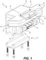
- FIG. 1is a perspective view from the top of a base member of a coupling system and including a portion in exploded view, according to certain embodiments of the present disclosure.
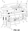
- FIG. 2 Ais a perspective view from the top of the base member of FIG. 1 and including another portion in exploded view, and with a retractable stop member in an extended position; according to certain embodiments of the present disclosure.
- FIG. 2 Bis a perspective view from the top of an alternate embodiment of the base member of FIG. 1 and including a portion in exploded view, and with a retractable stop member in an extended position; according to certain embodiments of the present disclosure.
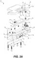
- FIG. 3 Ais a perspective view from the top of the base member of FIG. 1 and including other portions in exploded view, according to certain embodiments of the present disclosure.
- FIG. 3 Bis a perspective view from the top of the base member of FIG. 2 B and including other portions in exploded view, according to certain embodiments of the present disclosure.
- FIG. 4 Ais a perspective view from the bottom of the base member of FIG. 1 and including portions in exploded view, according to certain embodiments of the present disclosure.
- FIG. 4 Bis a perspective view from the bottom of the base member of FIG. 2 B and including portions in exploded view, according to certain embodiments of the present disclosure.
- FIG. 5 Ais a perspective view from the top of a patient transport system and including the base member of FIGS. 2 B, 3 B and 4 B , according to certain embodiments of the present disclosure.
- FIG. 5 Bis a perspective view from the bottom of the patient transport system of FIG. 5 A , according to certain embodiments of the present disclosure.
- FIG. 5 Cis a perspective view from the top of a supporting rail assembly of the patient transport system of FIG. 5 A , according to certain embodiments of the present disclosure.
- FIG. 6is a perspective view of a patient transport system and including the base member of FIGS. 2 B, 3 B and 4 B and a positioning member, according to certain embodiments of the present disclosure.
- FIG. 7is a perspective view of the patient transport system and including the base member of FIG. 6 with the positioning member attached thereto, according to certain embodiments of the present disclosure.
- FIG. 8is a perspective view of another embodiment of a patient transport system and including the base member of FIGS. 1 , 2 A, 3 A and 4 A , according to certain embodiments of the present disclosure.
- FIG. 9is a perspective view of the patient transport system and including the base member of FIG. 8 and a positioning member, according to certain embodiments of the present disclosure.
- FIG. 10is a perspective view of the patient transport system and including the base member of FIG. 9 with the positioning member attached thereto, according to certain embodiments of the present disclosure.
- FIG. 11is a perspective view of the patient transport system and base member of FIG. 9 with another embodiment of the positioning member attached thereto, according to certain embodiments of the present disclosure.
- FIG. 12is the patient transport system, base member and positioning member of FIG. 11 , with equipment attached to an equipment frame of the positioning member using connecting devices, according to certain embodiments of the present disclosure.
- FIG. 13is a clamp for attaching the equipment frame of a positioning member to the patient transportation system, according to certain embodiments of the present disclosure.
- FIG. 14is an equipment frame comprising a positioning member of the coupling system, and a base member of a connecting device attached thereto, according to certain embodiments of the present disclosure.
- FIG. 15is the equipment frame of FIG. 14 attached to a stretcher, according to certain embodiments of the present disclosure.
- FIG. 16is a connecting device comprising a base member, a release member, and a top plate, according to certain embodiments of the present disclosure.
- FIG. 17is the connecting device of FIG. 16 , with the top plate removed for clarity, when in the coupled and lock position, according to certain other embodiments of the present disclosure.
- FIG. 18is the connecting device of FIG. 16 , when in the uncoupled and unlock position, according to certain other embodiments of the present disclosure.
- FIG. 19is an exploded view of the base member of FIG. 16 , according to certain other embodiments of the present disclosure.
- FIG. 20is a cross-sectional view of the connecting device of FIG. 16 , according to certain other embodiments of the present disclosure.
- FIG. 21is an exploded view of the base member and the release member of FIG. 16 , according to certain other embodiments of the present disclosure.
- FIG. 22is an exploded view of the release member of FIG. 16 and a lock mechanism, according to certain other embodiments of the present disclosure.
- FIG. 23is an exploded view of the release member of FIG. 16 and a lock mechanism, according to certain other embodiments of the present disclosure.
- FIG. 24is the base member of FIG. 16 and a damping member, according to certain other embodiments of the present disclosure.
- FIG. 25is a connecting device comprising a base member, a release member, and a top plate, according to certain other embodiments of the present disclosure.
- FIG. 26is the connecting device of FIG. 25 , with the top plate removed for clarity, and including a circular member, according to certain embodiments of the present disclosure.
- the patient transport system 14comprises a personal transport system arranged to transport a patient.
- the personal transport system 14is a stretcher.
- the stretchermay be a stretcher adapted for aircraft use ( FIGS. 5 A-C , 6 and 7 ) or a stretcher adapted for ground use ( FIGS. 8 - 11 ). It is understood that the present technology can be used with stretchers of various configurations, such as, for instance, stretchers with narrow footprints, wide footprints, with side rails and/or arm boards.
- Embodiments of the coupling system 10can also be used with other patient transport systems 14 such as wheelchairs, beds or the like (not shown).
- the patient transport system 14comprises a frame 16 , a support body 18 attachable to the frame 16 for supporting the patient, and optionally wheels 20 attachable to the frame 16 ( FIGS. 8 - 12 ).
- the support body 18may comprise a mattress removably attachable to the frame 16 by fasteners (not shown) such as a hooks, clasps, velcro, etc.
- the equipment 12may be any suitable equipment such as medical equipment, which may or may not be mobile.
- the mobile equipmentcan be any type of equipment that accompanies a patient on the patient transport system 14 , such as, but not limited to, ventilators, pumps, monitoring equipment, screen, drips, etc.
- equipment 12is also meant any structural support for the equipment, such as frames etc.
- FIG. 12illustrates the use of the coupling system 10 to attach medical equipment 12 to a stretcher 14 .
- the coupling system 10comprises a base member 22 connectable to the patient transport system 14 , and a positioning member 24 connectable to the equipment 12 (whether directly or indirectly).
- the positioning member 24is arranged to be coupled to the base member 22 to attach the equipment 12 to the patient transport system 14 , and to be decoupled from the base member 22 to detach the equipment 12 from the patient transport system 14 .
- the coupling system 10can be said to have two operation modes: a coupled mode when the positioning member 24 is coupled to the base member 22 and cannot be separated therefrom, and a release mode when the positioning member 24 is released from the base member 22 and can be separated therefrom.
- the base member 22 and the positioning member 24are configured to be coupled and released in a convenient manner as will be described in further detail below.
- the base member 22comprises a recessed portion 26 having a base 28 and a wall 30 , and a retractable stop member 32 .
- the retractable stop member 32is arranged to extend into the recessed portion 26 , though an opening 34 in the base 28 (best seen in FIG. 2 A ), when in the coupled mode (“extended position” of the retractable stop member 32 ). In the release mode, the retractable stop member 32 is retracted through the opening 34 and does not extend into the recessed portion 26 (“retracted position” of the retractable stop member).
- a channel 36is defined in the recessed portion 26 by the retractable stop member 32 and the wall 30 of the recessed portion 26 , the channel 36 being arranged to receive an end portion 38 of the positioning member 38 for engagement with the wall 30 of the recessed portion 26 and the retractable stop member 32 .
- the recessed portion 26has an open access end 40 through which the positioning member 24 can be slidingly inserted and removed from the recessed portion 26 .
- the recessed portion 26has a rectangular configuration, with the wall 30 extending along three of the four sides, and the open access end 40 being the one side without the wall 30 extending along it.
- the retractable stop member 32has a profile 42 which is wedge-shaped, such that a height 44 of the retractable stop member 32 is decreased towards the open access end 40 of the recessed portion 26 .
- the retractable stop member 32has an actuation system 46 permitting actuation of the retractable stop member 32 between the retracted position and the extended position.
- the actuation system 46comprises a resiliently biased actuator connected to the retractable stop member.
- the resiliently biased actuatorcomprises a handle 48 connected to the retractable stop member 32 by at least one pin 50 , and at least one resilient member 52 , such as a spring extending along the pin 50 , for resiliently biasing the handle 48 towards the retractable stop member 32 , and for resiliently biasing the retractable stop member 32 in the extended position.
- a cover 54may be provided for covering each spring 52 and pin 50 combination.
- the base member 22has a three part configuration: (i) an upper portion 56 ; (ii) a lower portion 58 connected to the upper portion 56 , and (iii) a retractable stop member portion 60 moveably arranged between the upper portion 56 and the lower portion 58 .
- portions of the base member 22may be one-piece.
- the upper portion 56comprises an upper body 62 having the recessed portion 26 defined therein and having the base 28 and the wall 30 , and the opening 34 defined in the base 28 through which the retractable stop member 32 can extend and retract.
- the lower portion 58comprises a lower body 64 having an upper face 66 , the upper face 66 being adapted to moveably house the retractable stop member portion 60 .
- the upper face 66has a recess 68 which is sized and shaped to receive the retractable stop member portion 60 .
- a lower face 70 of the lower body 64is arranged to be connectable to the patient transport system 14 by a clamp 72 .
- the lower portion 58may be attached to the upper portion 56 by any fastener, such as a screw.
- the clamp 72may be attached to the lower body 64 by any fastener, such as a screw.
- the base member 22is connected to the patient transport system 14 through a clamp 73 formed by the upper face 66 of the lower body 64 and a lower face 63 of the upper body 62 .
- the upper face 66 of the lower body 64 and a lower face 63 of the upper body 62are oppositely facing and define a slot configured to receive, and enclose, a portion of the frame 16 when attached thereto by bringing the lower body 64 and the upper body 62 closer together.
- the base member 22 of FIGS. 2 B, 3 B, 4 Bdiffers from the base member 22 of FIGS. 2 A, 3 A, 4 A in the manner in which it can be attached to the patient transport system.
- the base member 22 of FIGS. 2 B, 3 B, 4 Bis provided with the clamp 73 associated with the upper and lower bodies 62 , 64 .
- FIGS. 2 A, 3 A and 4 Aembodiments of the base member 22 as illustrated in FIGS. 2 A, 3 A and 4 A , as well as FIGS. 2 B, 3 B, 4 B are separate and connectable to the frame 16 of the equipment 12 .
- the base member 22 of FIGS. 2 B, 3 B, 4 B as connected to the patient transport system 14is illustrated in FIGS. 5 A-C , 6 and 7 .
- the base member 22may be connected to the patient transport system 14 in any other manner.
- the base member 22could be connected to the patient transport system 14 with another type of clamp or clasp or with fasteners.
- At least a portion of the base member 22may be integrally formed with the frame 16 of the patient transport system 14 .
- the retractable stop member portion 60comprises a plate portion 74 , sized and shaped to be received in the recess 68 of the upper face 66 of the lower body 64 , and the retractable stop member 32 extending upwardly from the plate portion 74 .
- the handle 48may have a grip portion 76 which may be ergonomically shaped for a grip of a user's hand or fingers.
- the pins 50extend through openings 78 in the recess 68 of the lower plate upper face 66 and are arranged to be slidingly moved up and down in the openings 78 .
- a stopper 80may be provided at an end of the pin 50 to ensure retention of the retractable stop member portion 60 with the pin 50 .
- the retractable stop member 32can be said to be moveably connected to the lower portion 58 with the pins 50 guiding the movement.
- the resilient members 52are provided, one on each pin 50 and extending between the lower portion 58 and the handle 48 to resiliently bias the retractable stop member 32 away from the handle 48 , and hence in the extended position, when the base member 22 is at steady state (i.e. no actuation on the handle 48 ). Pulling downwardly on the handle 48 in the release phase compresses the springs 52 , and brings the retractable stop member 32 downwardly so that the retractable stop member 32 is retracted from the opening 34 of the of the base member 22 . This causes the disengagement between the positioning member 24 and the retractable stop member 32 to allow them to be separated.
- guide members 82are provided which are integral with, or formed separately and attachable to, the patient transport system 14 (shown in FIGS. 5 A-C , 6 - 13 ).
- the guide members 82are arranged to receive arms 84 of an equipment frame 96 attached to the positioning member 24 .
- two guide members 82are configured to receive the same arm 84 .
- Each guide member 82comprises a guide member body 86 defining an arm opening 88 a for receiving the arm 84 .
- the arm opening 88 ahas a circular profile for receiving circular cross-sectional arms 84 , in the embodiments illustrated herein.
- Other profiles of arms 84 and arm openings 88 a of the guide member 82are also possible but not shown.
- the guide member body 86also defines a frame opening 88 b for receiving the frame 16 .
- the guide member body 86has a two-part configuration.
- the arm opening 88 ais formed within one of the two parts whilst the frame opening 88 b is formed between the two parts such that the frame 16 can be retained in the frame opening 88 b by a clamping of the two parts together.
- the guide members 82can be considered as a connector of the frame 16 and the positioning member 24 .
- two pairs of guide members 82are provided, one pair per elongate side of the stretcher 14 , with the base member 22 being positioned between the two pairs of guide members 82 .
- Each pair of arm openings 88 a of the guide members along a respective elongate side of the stretcherare axially aligned so as to guide and hold in position the respective arm 84 . It will be appreciated that it is within the scope of the present technology to provide other numbers of guide members 82 or other configurations of the guide member 82 .
- the embodiment of the guide member 82 of FIG. 13differs from that of FIGS. 5 A-C in that the arm opening 88 a is positioned above the frame opening 88 b . Both the arm opening 88 a and the frame opening 88 b are formed between the two parts so as to retain both the arm 84 and the frame 16 by clamping the two parts together.
- Such a two-part configuration of the guide member 82 defining the frame opening 88 ballows for clamping around the frame 16 of the patient transport system 14 for a retroactive attachment of the coupling system 10 to the patient transport system 14 .
- the supporting rail assembly 85connectable to the guide members 82 .
- the supporting rail assembly 85includes a support rail 87 and two support cross members 89 a , 89 b .
- the support rail 87When connected, the support rail 87 is disposed below the frame 16 , extends along a portion of the frame 16 , and generally follows the shape thereof. A front portion of the support rail 87 may engage with the base member 22 .
- the two support cross members 89 a , 89 bare longitudinally spaced from one another, and are fastened to lateral sides of the support rail 87 .
- the two support cross members 89 a , 89 b and the guide rail 87may be connected in a different manner than as described and illustrated herein. It is also contemplated that the two support cross members 89 a , 89 b and the guide rail 87 may be integral. In other embodiments, there may be more or less than two support cross members 89 a , 89 b .
- the supporting rail assembly 85may provide additional stability to the coupling system 10 but is an optional feature. For clarity, in other embodiments, the supporting rail assembly 85 may be omitted.
- the positioning member 24comprises a positioning member body 92 having the end portion 38 adapted to be received in the channel 36 of the base member 22 .
- the end portion 38has a rectangular configuration which is sized and shaped to be received in the recessed portion 26 .
- the positioning member 24is hollow and walls of the positioning member 24 are sized and shaped to be received in the channel 36 . In other words, the walls of the positioning member 24 define a cavity, and when the positioning member 24 is placed on the base member 22 , the retractable stop member 32 extends into the cavity.
- the positioning member body 92has a connection end 94 , arranged to be connectable to the equipment 12 .
- the connection end 94is connected to the equipment frame 96 to which are connectable one or more pieces of equipment 12 using for example one or more connecting devices 120 , which will be described later with reference to FIGS. 16 - 26 .
- a platform 98may be provided attached to the equipment frame 96 for supporting the connecting device, or a portion of the connecting device 120 . Multiple platforms may be provided.
- the equipment frame 96comprises a cross-bar 100 to which the positioning member 24 is attached, and the two arms 84 extending transversely, and substantially parallel to one another, from each end of the cross-bar 100 .
- the arms 84are arranged to be received in the openings 88 defined in each guide member body 86 .
- the equipment frame 96may further comprise, in certain embodiments, at least one structural unit 104 for supporting one or more connecting devices, or at least some portions of the connecting devices.
- the structural support unit 104comprises vertical support arms 106 for supporting medical equipment at different positions and heights to one another.
- the structural support unit 104may also include a platform 98 .
- equipment 12can be secured to the patient transport system 14 by sliding the end portion 38 of the positioning member 24 through the open access end 40 of the recessed portion 26 . Due to the wedge shape of the retractable stop member 32 and the moveable connection of the retractable stop member 32 to the upper portion 56 of the base member 22 , the retractable stop member 32 is caused to move downwardly, to the retracted position, allowing the end portion 38 to be fully housed in the recessed portion 26 . Due to the resilient bias of the retractable stop member 32 to the extended portion, as soon as the end portion 38 of the positioning member 24 is fully received in the recessed portion 26 , the retractable stop member 32 moves upwardly to engage with the end portion 38 of the positioning member 24 and lock it into place.
- a notch(not shown) may be provided to prevent vertical separation between the base member 22 and the positioning member 24 .
- the positioning member 24can be decoupled from the base member 22 by pulling the handle 48 to overcome the resilient bias and to move the retractable stop member 32 downwardly and into the retracted position where it can no longer engage with the end portion 38 of the positioning member 24 .
- the connecting device 120may be used to releasably connect any two items or elements together, such as a first item and a second item.
- the first and second itemsmay comprise one or more of a support surface, a transportation device such as a wheelchair, a stretcher or a bed, equipment such as medical equipment, securing apparatus for equipment such as the securing apparatus 10 .
- the connecting device 120comprises a base member 134 connectable to a portion of the frame 16 , and a release member 136 connectable to the equipment 12 .
- the base member 134 and the release member 136are releasably connectable.
- the release member 136has a body 138 which may be plate-like and has a first side 140 and a second side 142 .
- the first side 140 of the release member body 138defines a planar contact face 144 for contacting the base member 134 .
- the second side 142 of the release member 136has a collar 146 extending therefrom, the collar 146 positioned inwardly of a perimeter 148 of the release member 136 to define a flange portion 150 of the release member 136 .
- the base member 134has a front side 152 and a back side 154 .
- the front side 152has a planar contact portion 156 for contacting the contact face 144 of the release member 136 .
- a shoulder 158extends around a portion of a periphery 160 of the planar contact portion 156 to define a pocket 162 for receiving at least a portion of the release member 136 .
- the shoulder 158is engageable with a portion of the flange 150 of the release member 36 when the release member 136 is positioned on the base member 134 .
- the base member front side 152has an open access end 164 through which the release member 136 can be slidingly inserted and removed from the pocket 162 .
- the base member 134is four-sided, with the shoulder 158 extending around three of the four sides and the fourth side being the open access end 164 . In other embodiments, the base member 134 may have different numbers of sides.
- a stop member 166is positioned in a recess 168 within the planar contact portion 156 of the base member 134 and is moveable relative to the planar contact portion 156 .
- the stop member 166is moveable to extend out of the recess 168 and to be housed fully in the recess 168 by a coupling lock mechanism 170 and an actuator 172 .
- the stop member 166is actuatable between a lock position in which at least a portion of the stop member 166 extends from the recess 168 and a release position in which the stop member 166 is retracted into the recess 168 and does not extend from the recess 168 .
- the stop member 166can abut an edge 174 of an opening 176 defined in the release member contact face 144 to delimit movement of the release member 36 towards the open access end 64 ( FIGS. 18 - 20 ).
- the release member 136can be decoupled from the base member 134 ( FIG. 20 ).
- the actuator 172is positioned at the open access end 164 .
- the actuator 172is a push button 178 housed within a groove 180 formed at the open access end 164 .
- the actuator 172can be moved between a neutral position and a deployed position.
- the stop member 166is resiliently biased towards the lock position.
- the coupling lock mechanism 170is arranged to move the stop member 166 to retract into the recess 168 in the release position. This can allow the release member 136 to be slid relative to the base member 134 and removed from the base member 134 .
- the actuator 172extends beyond a perimeter 182 of the base member 134 ( FIG. 26 ) when in the neutral position. In other embodiments, the actuator 172 does not extend beyond the perimeter 182 of the base member 134 ( FIGS. 16 - 18 ).
- the coupling lock mechanism 170comprises an actuator spring 184 resiliently biasing the actuator 172 outwardly to the neutral position, and a stop member spring 186 resiliently biasing the stop member 166 to the lock position.
- the actuator spring 184 and the stop member spring 186extend in directions which are substantially transverse to one another.
- the base member 134comprises a plurality of spring loaded ball bearings 188 partially extending from recesses 190 formed in the planar contact portion 156 of the front side 152 of the base member 134 and engageable with corresponding recesses 192 defined in the planar contact face 144 of the release member 136 .
- the spring loaded ball bearings 188 and the recesses 192can guide the movement of the release member 136 relative to the base member 134 .
- the planar contact face 144 of the release member 136comprises an anti-friction layer for reducing or minimizing friction between the contact faces 144 , 156 of the release member 136 and the base member 134 .
- the anti-friction layercomprises a disc 194 attached to the release member 136 and with an outer face 196 which is the planar contact face 144 and having anti-friction properties.
- the recesses 192 for receiving the spring loaded ball bearings 188are formed in the disc 194 .
- the anti-friction layercomprises a coating.
- the anti-friction layermay comprise any material that reduces friction between the base member 134 and the release member 136 .
- the connecting device 120further comprises a top plate 198 attachable to the collar 146 of the release member 136 and attachable to the equipment 12 .
- the top plate 198is attached to the collar 146 by fasteners 200 , such as screws.
- the top plate 198has an opening formed therein.
- the release member 136when the base member 134 and the release member 136 are coupled together and in the lock position, the release member 136 is rotatable within the pocket 162 whilst maintaining the coupling.
- the perimeter 148 of the plate-like body 138 of the release member 136is circular in shape
- the stop member 166 of the base member 134is positioned substantially centrally of the planar contact portion 156
- the opening 176 of the release member 136is positioned substantially centrally of the plate-like body 138 , such that the release member 136 can be rotated within the pocket 162 when the stop member 166 is in the lock position.
- the stop member 166can be considered to function also as a pivot point in these embodiments.
- the release member 136when the base member 134 and release member 136 are coupled together and in the lock position, the release member 136 is not rotatable within the pocket 162 .
- the perimeter 148 of the plate-like body 138 of the release member 136has an eccentric shape such that the release member 136 is not rotatable in the pocket 162 of the base member 134 .
- the perimeter 148 of the release member 136may have a shape which is a multi-faceted geometric form.
- This embodiment of the connecting device 120may be used when rotation of the equipment 12 is not required.
- the release member 136further comprises a circular member 206 which is rotatable within the pocket 162 ( FIG. 26 ).
- the connecting device 120is further provided with a damping member 208 ( FIG. 24 ) attachable to the back side 154 of the base member 134 and arranged to be positioned between the base member 134 and the surface in use.
- the damping member 208is arranged to absorb vibrations and shocks, and/or reduce energy transmission.
- the damping member 208is made of any suitable material such as elastomeric materials.
- the positioning memberis mounted, in certain embodiments, it is provided with at least the base member 134 of one or more connecting devices 120 .
- the corresponding release members 136would be attached to the equipment 12 , such as on a base of the equipment 12 .
- the base members 134 of three connecting devices 120are provided on the equipment frame 96 , more specifically one base member 134 attached to the vertical arm close to the cross-bar, and two other base members 134 attached to the platform 46 at a distal end of the vertical arms.
- the connecting device 120 provided close to the cross-barcorresponds to the non-rotatable embodiment illustrated in FIGS. 25 and 26 .
- the one or more connecting devices 120may have the same or different width.
Landscapes
- Health & Medical Sciences (AREA)
- Life Sciences & Earth Sciences (AREA)
- Animal Behavior & Ethology (AREA)
- General Health & Medical Sciences (AREA)
- Public Health (AREA)
- Veterinary Medicine (AREA)
- Nursing (AREA)
- Accommodation For Nursing Or Treatment Tables (AREA)
Abstract
Description
Claims (20)
Priority Applications (1)
| Application Number | Priority Date | Filing Date | Title |
|---|---|---|---|
| US17/802,299US12310901B2 (en) | 2020-02-28 | 2021-02-26 | Coupling systems for releasably coupling equipment to a patient transport systems |
Applications Claiming Priority (3)
| Application Number | Priority Date | Filing Date | Title |
|---|---|---|---|
| US202062983075P | 2020-02-28 | 2020-02-28 | |
| US17/802,299US12310901B2 (en) | 2020-02-28 | 2021-02-26 | Coupling systems for releasably coupling equipment to a patient transport systems |
| PCT/CA2021/050253WO2021168586A1 (en) | 2020-02-28 | 2021-02-26 | Coupling systems for releasably coupling equipment to a patient transport system |
Publications (2)
| Publication Number | Publication Date |
|---|---|
| US20230096795A1 US20230096795A1 (en) | 2023-03-30 |
| US12310901B2true US12310901B2 (en) | 2025-05-27 |
Family
ID=77491707
Family Applications (1)
| Application Number | Title | Priority Date | Filing Date |
|---|---|---|---|
| US17/802,299ActiveUS12310901B2 (en) | 2020-02-28 | 2021-02-26 | Coupling systems for releasably coupling equipment to a patient transport systems |
Country Status (4)
| Country | Link |
|---|---|
| US (1) | US12310901B2 (en) |
| EP (1) | EP4110256A4 (en) |
| CA (1) | CA3168971A1 (en) |
| WO (1) | WO2021168586A1 (en) |
Families Citing this family (4)
| Publication number | Priority date | Publication date | Assignee | Title |
|---|---|---|---|---|
| US11890118B2 (en) | 2021-03-24 | 2024-02-06 | Stryker Corporation | Patient support apparatus with support assembly for medical device |
| USD1018268S1 (en)* | 2021-08-16 | 2024-03-19 | The Braun Corporation | Wheelchair coupling mechanism |
| CA3199389A1 (en) | 2022-05-13 | 2023-11-13 | Technologies Cgc Inc. | Coupling device and base member for coupling device |
| EP4275668B1 (en)* | 2022-05-13 | 2025-04-02 | Technologies CGC Inc. | Support assembly attachable to a patient support and patient support having same |
Citations (218)
| Publication number | Priority date | Publication date | Assignee | Title |
|---|---|---|---|---|
| US4511158A (en) | 1982-08-27 | 1985-04-16 | Mt. Sinai Medical Center Of Greater Miami | Intravenous infusion pole attachment |
| US4887784A (en)* | 1989-03-02 | 1989-12-19 | Nk Innovations, Inc. | Adjustable drink holder |
| US4888922A (en)* | 1988-08-15 | 1989-12-26 | Richmond Screw Anchor Co., Inc. | Setting hoist anchors in poured concrete structures |
| US4892279A (en)* | 1987-05-04 | 1990-01-09 | Polymedical Technologies, Inc. | Fully portable medical I.V. equipment stand/pole |
| US4901967A (en)* | 1986-07-15 | 1990-02-20 | The Cleveland Clinic Foundation | Patient equipment transport and support system |
| US4905882A (en)* | 1988-12-28 | 1990-03-06 | Ross Judy L | Neck engaging support for medical device |
| US4905944A (en)* | 1989-01-26 | 1990-03-06 | Baxter International Inc. | Home care intravenous stand |
| US4915435A (en)* | 1989-04-05 | 1990-04-10 | Levine Brian M | Mobile operating room with pre and post-operational areas |
| US4925444A (en)* | 1987-08-07 | 1990-05-15 | Baxter Travenol Laboratories, Inc. | Closed multi-fluid delivery system and method |
| US4945592A (en)* | 1988-09-30 | 1990-08-07 | The General Hospital Corporation | Transport system for portable patient care apparatus |
| US4966340A (en)* | 1989-04-24 | 1990-10-30 | Hunter Rebecca L | Wheeled stand apparatus for hanging containers of medical fluids |
| US4969768A (en)* | 1989-09-28 | 1990-11-13 | Young Robert J | Coupler for IV pole |
| US4974377A (en)* | 1988-03-18 | 1990-12-04 | The Mitre Corporation | Integrated enclosure and adjustable electronic equipment mounting system |
| US4997150A (en)* | 1987-04-17 | 1991-03-05 | Lifter S.R.L. | Adjustable oleopneumatic support |
| US5007608A (en)* | 1989-08-28 | 1991-04-16 | Kim Manufacturing Company | Television wall bracket |
| US5016307A (en)* | 1990-03-23 | 1991-05-21 | Linda Rebar | Integral stretcher and intravenous fluid carrier/gravity dependent drainage support |
| US5078349A (en)* | 1990-04-16 | 1992-01-07 | Midmark Corporation | Locking mechanism for an IV pole |
| US5083807A (en)* | 1990-12-18 | 1992-01-28 | Church Home & Hospital Of The City Of Baltimore | IV stand coupling device |
| US5094418A (en)* | 1990-09-07 | 1992-03-10 | Stryker Corporation | IV pole |
| US5110076A (en)* | 1991-01-14 | 1992-05-05 | Cal-Surgical, Inc. | Adjustable multipole support stand for medical fluids |
| US5112019A (en)* | 1991-02-04 | 1992-05-12 | Storz Instrument Company | Motorized IV pole assembly |
| US5125607A (en)* | 1991-01-08 | 1992-06-30 | Pryor Products | Stable support stand adapted for flat storage |
| US5135191A (en)* | 1991-05-09 | 1992-08-04 | Jagco Corporation | Medical support system |
| US5149036A (en)* | 1991-08-29 | 1992-09-22 | Sheehan Gerald F | Device for attaching an IV pole to a hospital bed or the like |
| US5152486A (en) | 1991-04-12 | 1992-10-06 | Kabanek Joseph R | Operating room table mate |
| US5157409A (en)* | 1991-08-07 | 1992-10-20 | Radio Frequency Systems, Inc. | Cam lock antenna mounting assembly |
| US5207303A (en)* | 1991-07-15 | 1993-05-04 | Oswalt Brenda K | Medical emergency carrying case |
| US5207642A (en)* | 1987-08-07 | 1993-05-04 | Baxter International Inc. | Closed multi-fluid delivery system and method |
| US5219139A (en)* | 1992-06-25 | 1993-06-15 | Barnes Hospital | Device for connecting an IV pole to a wheelchair |
| US5224681A (en)* | 1990-04-13 | 1993-07-06 | Lundstrom Donald A | Hand releasable locking collar |
| US5306109A (en)* | 1991-04-23 | 1994-04-26 | Kreuzer Gmbh & Co. Ohg | Transportable medical apparatus, in particular infusion supply |
| US5319816A (en)* | 1992-12-07 | 1994-06-14 | Hill-Rom Company, Inc. | IV rack transferrable from an IV stand to a hospital bed |
| US5326059A (en)* | 1992-12-23 | 1994-07-05 | Pryor Products | Quick clamping system |
| US5337992A (en)* | 1993-02-08 | 1994-08-16 | Pryor Products, Inc. | Support device for ambulatory patient |
| US5344169A (en)* | 1992-01-27 | 1994-09-06 | Pryor Products | Multi-pole support stand |
| US5362021A (en) | 1992-05-11 | 1994-11-08 | Phillips Medical Group, Inc. | Multi-adjustable surgical tray apparatus |
| US5366191A (en)* | 1992-02-19 | 1994-11-22 | Joseph Bekanich | Support apparatus for a patient infusion device |
| US5383629A (en)* | 1992-10-07 | 1995-01-24 | Air Methods Corporation International | Emergency medical system |
| US5392350A (en)* | 1992-05-18 | 1995-02-21 | Swanson; Paul J. | Support apparatus for a transportable telephone |
| US5400995A (en)* | 1992-04-15 | 1995-03-28 | Hill-Rom Company, Inc. | IV pole with interior drag brake |
| US5407163A (en)* | 1993-11-19 | 1995-04-18 | Hill-Rom Company, Inc. | Sliding IV pole |
| US5421548A (en)* | 1994-04-01 | 1995-06-06 | Bennett; James R. | I.V. stand and attachments |
| US5425520A (en)* | 1992-03-18 | 1995-06-20 | Hideki Ueda | Corner bracket for use in a sectional shelf |
| US5490703A (en)* | 1993-06-04 | 1996-02-13 | Vancouver Island Helicopters Ltd. | Patient transport system |
| US5527125A (en)* | 1992-08-17 | 1996-06-18 | Kreuzer Gmbh & Co. Ohg | Transportable medical apparatus, in particular infusion supply apparatus |
| US5556065A (en)* | 1994-10-19 | 1996-09-17 | Wadley; Robert D. | Intensive care equipment carriage |
| US5588166A (en)* | 1995-01-04 | 1996-12-31 | Burnett; John | Medical attachment device |
| US5615848A (en)* | 1993-12-23 | 1997-04-01 | Agusta Eli S.R.L. | Rescue and ambulance helicopter |
| US5618090A (en)* | 1995-05-12 | 1997-04-08 | Medaes, Inc. | Movable hospital room equipment column |
| US5626320A (en)* | 1994-12-30 | 1997-05-06 | Garmin Corporation | Mounting bracket for use with aircraft yokes |
| US5647491A (en)* | 1992-04-15 | 1997-07-15 | Hill-Rom Company, Inc. | IV rack |
| US5657884A (en)* | 1996-02-21 | 1997-08-19 | Metaline Products Company Inc. | Display pole support structure |
| US5664750A (en)* | 1995-11-14 | 1997-09-09 | Cohen; Edward | Camera Mount |
| US5699988A (en)* | 1993-01-19 | 1997-12-23 | St. Francis Research Institute | Coupler clamping apparatus for interconnecting a free-standing, wheeled intravenous pole with mobile patient transfer devices |
| US5704577A (en)* | 1995-10-11 | 1998-01-06 | Gordon; Gray J. | Walker-IV stand coupler |
| US5732965A (en)* | 1996-02-07 | 1998-03-31 | Willey; Barry A. | Mounting system for motorcyle accessories |
| US5732867A (en)* | 1996-11-26 | 1998-03-31 | Crush Innovative Sports Systems, Inc. | Releasable backpack |
| US5738306A (en)* | 1995-10-13 | 1998-04-14 | Air Methods Corporation | Articulating patient loading system and transport device for aircraft |
| US5755478A (en)* | 1995-06-06 | 1998-05-26 | Northrop Grumman Corporation | Mobile self-contained trauma care system |
| US5779296A (en)* | 1993-06-04 | 1998-07-14 | Vancouver Island Helicopters, Ltd. | Patient transport system |
| US5785277A (en)* | 1995-10-13 | 1998-07-28 | Air Methods Corporation | Patient loading system and transport device for aircraft |
| US5815629A (en)* | 1995-08-18 | 1998-09-29 | Siemens Aktiengesellschaft | Cap sleeve for light waveguide cables |
| US5829723A (en)* | 1995-06-28 | 1998-11-03 | Medex, Inc. | Medical device mounting structure |
| US5833095A (en)* | 1997-12-05 | 1998-11-10 | Task Corporation | Tool and fastener holder with detachable holding belt |
| US5850891A (en)* | 1997-10-30 | 1998-12-22 | Trimble Navigation Limited | Motorized rack system |
| US5857685A (en)* | 1995-08-09 | 1999-01-12 | Phillips; James R. | Support cart apparatus for supporting intravenous fluid dispensing systems |
| US5865314A (en)* | 1996-06-21 | 1999-02-02 | Medport, Inc. | Case for injectable medication with cooling compartment |
| US5876016A (en)* | 1997-05-14 | 1999-03-02 | Urban; Theodore A. | Apparatus and method to elevate an infusion source |
| US5878536A (en)* | 1997-05-28 | 1999-03-09 | The Charlotte-Mecklenburg Hospital Authority | Neonatal infant care headwall |
| US5886674A (en)* | 1996-02-29 | 1999-03-23 | Mitsubishi Denki Kabushiki Kaisha | Antenna mount |
| US5898961A (en)* | 1995-06-07 | 1999-05-04 | Hill-Rom, Inc. | Mobile support unit and attachment mechanism for patient transport device |
| US5924658A (en)* | 1998-01-07 | 1999-07-20 | Stryker Corporation | IV pole |
| US5966760A (en)* | 1997-01-31 | 1999-10-19 | Hill-Rom, Inc. | Apparatus and method for upgrading a hospital room |
| US5987670A (en)* | 1998-04-23 | 1999-11-23 | The General Hospital Corporation | Medical equipment transport system |
| US5988409A (en)* | 1995-07-21 | 1999-11-23 | Industrial Wire Products, Inc. | Vertical wall rack and variable shelf arrangement |
| US5996957A (en)* | 1998-04-02 | 1999-12-07 | Kurtz; Thomas M. | Rotational beverage holder |
| US6000509A (en)* | 1997-11-26 | 1999-12-14 | Kingport International Corporation | Compartmented suitcase |
| US6056249A (en)* | 1998-02-25 | 2000-05-02 | Fillon, Jr.; Charles W. | Device for allowing a person to be connected to and walk with various medical equipment |
| US6157350A (en)* | 1999-10-07 | 2000-12-05 | Motorola, Inc. | Antenna latching mechanism |
| US6155743A (en)* | 1998-12-09 | 2000-12-05 | Tay-E Co., Ltd. | Anchoring fixture for holding a musical instrument |
| US6170102B1 (en)* | 1997-11-18 | 2001-01-09 | Kreuzer Gmbh & Co. Ohg | Operating equipment |
| US6179260B1 (en)* | 1998-06-10 | 2001-01-30 | N. Sean Ohanian | Device for coupling an IV stand to a patient transport |
| US6182662B1 (en)* | 1998-07-23 | 2001-02-06 | Mcghee Chad J. | Intravenous transport/support device |
| US6213481B1 (en)* | 1998-07-01 | 2001-04-10 | Alm | Assembly consisting of a support structure and of a trolley for transporting equipment |
| US6231016B1 (en)* | 1999-06-09 | 2001-05-15 | Beth A. Slone | Medical support carrier |
| US6241109B1 (en)* | 1999-02-05 | 2001-06-05 | Interlake Material Handling, Inc. | Load lock for rack |
| US6244553B1 (en)* | 2000-02-02 | 2001-06-12 | Chin-Yang Wang | Fastening device for electronic equipment |
| US6244400B1 (en)* | 2000-01-10 | 2001-06-12 | Susan D. Bowers | Personalized, modularized carrying case |
| US6273366B1 (en)* | 1998-06-19 | 2001-08-14 | Daimlerchrysler Aerospace Airbus Gmbh | Patient transport arrangement in an aircraft |
| US6296094B1 (en)* | 1999-03-11 | 2001-10-02 | Wendy S. Knecht | Combination cosmetic bag and travel bag with multiple carrying modes |
| US6317497B1 (en)* | 1999-05-12 | 2001-11-13 | Jack Ou | Toggle joint combination for extending a receptacle of automobile cigarette lighter and application thereof |
| US6315182B1 (en)* | 2000-07-20 | 2001-11-13 | Co-Union Industry Co., Ltd. | Cellular phone pouch assembly adapted to be mounted on a bar |
| US20020011543A1 (en) | 2000-03-23 | 2002-01-31 | Chinn Robert C. | IV pole |
| US6366672B1 (en)* | 1999-11-10 | 2002-04-02 | Wen-Feng Tsay | Mobile phone holder |
| US6367603B1 (en)* | 2000-02-04 | 2002-04-09 | 500 Group, Inc. | Containment article having a pair of hingedly connected, substantially identical plastic shells and related improvements |
| US6375133B1 (en)* | 1998-03-04 | 2002-04-23 | Emergent Innovations, Llc. | Intravenous (IV) pole for transport with multiple infusion devices |
| US20020047075A1 (en)* | 2000-06-05 | 2002-04-25 | Metz Darrell L. | Medical accessory support |
| US6390311B1 (en)* | 2000-07-31 | 2002-05-21 | Martin Paul, Inc. | Ambulatory dispenser rack |
| US6390424B1 (en)* | 2000-07-13 | 2002-05-21 | Margo Kidushim | Accessory support device and method |
| US6394403B1 (en)* | 2000-10-26 | 2002-05-28 | Ray Hung | Supporting device for a liquid crystal display |
| US20020104934A1 (en)* | 1998-03-04 | 2002-08-08 | Emergent Innovations, Llc | Intravenous (IV) pole supporting systems |
| US6434329B1 (en)* | 1999-05-13 | 2002-08-13 | L'universite De Montreal | Controllable camera support and system |
| US20030014817A1 (en)* | 2001-05-25 | 2003-01-23 | Gallant Dennis J. | Architectural system adaptable to patient acuity level |
| US20030037375A1 (en)* | 2001-08-23 | 2003-02-27 | Riley Carl W. | Hospital bed equipment support apparatus |
| US20030046764A1 (en) | 2000-09-25 | 2003-03-13 | Smeed Eric M. | Critical care platform for litters |
| US6585188B2 (en)* | 2001-04-04 | 2003-07-01 | Agusta S.P.A. | Rescue vehicle |
| US6592090B1 (en)* | 2002-08-23 | 2003-07-15 | Chin-Chu Li | Object supporting structure |
| US6595379B1 (en)* | 2002-02-01 | 2003-07-22 | United Steel Enterprises, Inc. | Lock for preventing inadvertent removal of a first frame component of an adjustable storage system from a second frame component of the adjustable storage system and the adjustable storage system |
| US20030143052A1 (en)* | 2002-01-30 | 2003-07-31 | Arinc Incorporated | Medical evacuation patient support pallet |
| US6601860B2 (en)* | 2000-04-10 | 2003-08-05 | Angie Potter | Wagon for use in a hospital |
| US20030150445A1 (en)* | 2001-11-01 | 2003-08-14 | Aerogen, Inc. | Apparatus and methods for delivery of medicament to a respiratory system |
| US6618018B1 (en)* | 2001-11-08 | 2003-09-09 | Bellsouth Intellectual Property Corporation | Mounting assembly for mounting antenna to vehicle |
| US20030201370A1 (en)* | 2002-04-24 | 2003-10-30 | Advancetec Industries, Inc. | Mounting device |
| US6708991B1 (en)* | 2002-07-05 | 2004-03-23 | Art Ortlieb | Ambulatory IV dolly |
| US6726075B1 (en)* | 2001-06-27 | 2004-04-27 | Rajiv P. Patel | Modular tool and materials carrying apparatus |
| US6725483B2 (en)* | 1997-01-31 | 2004-04-27 | Hill-Rom Services, Inc. | Apparatus and method for upgrading a hospital room |
| US6746138B1 (en)* | 2002-05-28 | 2004-06-08 | Genlyte Thomas Group Llc | Support plate for a luminaire |
| US6762727B2 (en)* | 2001-10-09 | 2004-07-13 | Tyco Electronics Corporation | Quick-attach, single-sided automotive antenna attachment assembly |
| US6769657B1 (en)* | 2003-04-09 | 2004-08-03 | Min Hwa Huang | Support device for monitor, display or objects |
| US6789714B1 (en)* | 2002-07-05 | 2004-09-14 | Kerry J. Benson | Movable rack item storage system |
| US20040178309A1 (en)* | 2003-03-13 | 2004-09-16 | Crowley Robert O. | Support system for loads |
| US20040199999A1 (en)* | 2002-02-15 | 2004-10-14 | Jo-Ann Landry | Crib safety sheet/blanket |
| US20040253856A1 (en)* | 2003-03-18 | 2004-12-16 | Erco Leuchten Gmbh | Current-rail adapter |
| US20050000019A1 (en)* | 2003-03-18 | 2005-01-06 | Newkirk David C. | Patient care equipment management system |
| US20050006542A1 (en)* | 2003-07-11 | 2005-01-13 | Henning Gerald W. | Flat panel monitor support arm |
| US20050039644A1 (en)* | 2003-08-18 | 2005-02-24 | Sheahan Kevin Patrick | Modular workbench |
| US6896231B1 (en)* | 2003-01-23 | 2005-05-24 | Thomas E. Sullivan, Sr. | Articulated drink holder assembly for disabled persons |
| US6945414B1 (en)* | 2002-10-18 | 2005-09-20 | Products Of Tomorrow, Inc. | Wall panel and system |
| US20050232519A1 (en)* | 2004-04-15 | 2005-10-20 | Grimes Charles O Jr | Sock laundry and storage utility device |
| US20050230575A1 (en) | 2004-04-16 | 2005-10-20 | Zelenski Karen M | Mobile fluid delivery system with detachable pedestal |
| US6962306B2 (en)* | 2002-07-15 | 2005-11-08 | West Ronald R | Units for storing flexible elongated objects |
| US7048242B2 (en)* | 2003-06-13 | 2006-05-23 | Innovative Office Products, Inc. | Tilter apparatus for electronic device having bias assembly |
| US7097204B2 (en)* | 2002-07-22 | 2006-08-29 | Indiana Mills & Manufacturing, Inc. | Sleeper bunk restraint system |
| US20060242763A1 (en)* | 2003-10-13 | 2006-11-02 | Graham Mark A | Transferable patient care equipment support |
| US20060243766A1 (en)* | 2005-04-29 | 2006-11-02 | Jeff Lan | Mobile electronic audio-visual product carrier |
| US7135634B2 (en)* | 2004-05-28 | 2006-11-14 | Yoga Electronics Co., Ltd. | Mounting device for a microphone |
| US20060255221A1 (en)* | 2005-05-16 | 2006-11-16 | Chun-Hsien Tseng | Bracket device |
| US20060278785A1 (en)* | 2005-05-26 | 2006-12-14 | Sherwood Services Ag | Flexible clamping apparatus for medical devices |
| US7150058B2 (en)* | 2003-02-28 | 2006-12-19 | Sunrise Medical Hhg Inc. | Assist handle assembly for beds |
| US20070056921A1 (en)* | 2005-09-09 | 2007-03-15 | Lo Wen P | Adjustable wall rack |
| US20070097617A1 (en)* | 2005-10-31 | 2007-05-03 | Searby Tom J | Electronic device quick connect system |
| US7234619B2 (en)* | 2003-11-03 | 2007-06-26 | International Automotive Components Group North America, Inc. | Accessory strip for securing articles within a vehicle interior |
| US20070215766A1 (en)* | 2006-03-17 | 2007-09-20 | Yen Shu C | Hands-free device capable of adjusting an angle of its mounting seat in any direction and positioning same |
| US20070267550A1 (en)* | 2006-02-27 | 2007-11-22 | Peter Blankenship | Transformable intravenous pole |
| US20080023976A1 (en)* | 2006-07-28 | 2008-01-31 | Myers Will J | Patient support system for medical transport vehicles |
| US20080061195A1 (en)* | 2006-09-11 | 2008-03-13 | Carnevali Jeffrey D | Universal pole caddy |
| US20080073477A1 (en)* | 2001-12-21 | 2008-03-27 | Heinrich Lang | Linkage arrangement for the adjustment of rearview mirrors |
| US20080121730A1 (en)* | 2006-04-19 | 2008-05-29 | Calkin Carston R | Medical chest bag for military, emergency rescue and other personnel |
| US20080179478A1 (en)* | 2006-06-12 | 2008-07-31 | Michael Lee | Adaptor for vehicle mounts |
| US20080217910A1 (en) | 2007-03-09 | 2008-09-11 | Hill-Rom Services, Inc. | Trasferable patient care equipment support |
| US20080272254A1 (en)* | 2007-05-04 | 2008-11-06 | Tyco Healthcare Group Lp | Medical Device Safety Support with Infinite Positioning |
| US20080302553A1 (en)* | 2007-06-07 | 2008-12-11 | Ross Steven L | Data and Power Distribution System for an Electrical Busway |
| US20090014584A1 (en)* | 2005-05-19 | 2009-01-15 | Telezygology Inc | Tracks, Power, and Data Blocks and Releasable Fastening System |
| US7507005B1 (en)* | 2007-01-30 | 2009-03-24 | Genlyte Thomas Group Llc | Sliding flexible track lighting |
| US7510155B2 (en)* | 2007-07-02 | 2009-03-31 | Shian-Nung Huang | Single spring supporting device |
| US20090140112A1 (en)* | 2007-11-30 | 2009-06-04 | Carnevali Jeffrey D | Dual T-slot adaptor |
| US7546993B1 (en)* | 2008-03-25 | 2009-06-16 | Tyco Healthcare Group Lp | Flexible clamping apparatus for medical devices |
| US20090165208A1 (en)* | 2007-12-31 | 2009-07-02 | Monster Medic, Inc. | Ambulance cot system |
| US7600619B2 (en)* | 2003-06-02 | 2009-10-13 | Perfect World Luggage, Inc. | Storage container and display system for toys and other items |
| US7654834B1 (en)* | 2008-05-05 | 2010-02-02 | Genlyte Thomas Group, Llc | Track lighting assembly |
| US7669945B2 (en)* | 2004-11-05 | 2010-03-02 | Liebherr-Hausegeraete Ochsenhausen Gmbh | Refrigerating or freezing apparatus |
| US7669816B2 (en)* | 2005-04-15 | 2010-03-02 | Seco Manufacturing Company, Inc. | Clamp for mount system |
| US7677400B2 (en)* | 2005-04-07 | 2010-03-16 | Adc Telecommunications, Inc. | Cable management assembly, system and method |
| US7793902B2 (en)* | 2007-05-10 | 2010-09-14 | Gaymar Industries, Inc. | Medical device clamp |
| US7798323B1 (en)* | 2009-06-19 | 2010-09-21 | Dhs Systems Llc | Portable medical emergency equipment pack |
| US20100249513A1 (en)* | 2009-03-31 | 2010-09-30 | Jay Tydlaska | Laryngoscope and system |
| US20100307649A1 (en)* | 2008-01-15 | 2010-12-09 | Elite Bags, Sl | First-aid case for home visits |
| US20100314517A1 (en)* | 2009-06-12 | 2010-12-16 | Smiths Medical Asd, Inc. | Pole Clamp |
| US7946771B2 (en)* | 2005-06-13 | 2011-05-24 | Gvbb Holdings S.A.R.L. | Camera support and respective camera assembly |
| US20110121149A1 (en)* | 2006-05-19 | 2011-05-26 | Arnold Herskovic | Clamping device |
| US20110147428A1 (en)* | 2009-12-17 | 2011-06-23 | Tom Crawford | Tool Retention Device |
| US7984889B2 (en)* | 2008-06-18 | 2011-07-26 | Peerless Industries, Inc. | Rotatable mount for a display |
| US8020825B2 (en)* | 2006-11-16 | 2011-09-20 | Stryker Corporation | Utility clip |
| US20120006873A1 (en)* | 2010-07-12 | 2012-01-12 | Ferno-Washington, Inc. | Litter support systems for medical care units and methods of their use |
| US20120032038A1 (en)* | 2010-08-05 | 2012-02-09 | Hon Hai Precision Industry Co., Ltd. | Display support device and display using the same |
| US8167259B2 (en)* | 2009-04-06 | 2012-05-01 | Baxter International Inc. | Rapid attach and release clamps |
| US8167131B1 (en)* | 2010-06-10 | 2012-05-01 | Anderson Debra A | Carrying device for art and craft supplies |
| US8172077B1 (en)* | 2011-03-01 | 2012-05-08 | Gray Jack D | Portable workstation |
| US20120126075A1 (en)* | 2010-05-26 | 2012-05-24 | Ferno-Washington, Inc. | Mounting Device Providing A Pivotal Interface For Attachment Of Emergency Equipment Thereto And A Method Thereof |
| US8261954B2 (en)* | 2010-02-24 | 2012-09-11 | High Gear Specialties, Inc. | Mount with anti-rotation feature |
| US20120234992A1 (en)* | 2011-03-15 | 2012-09-20 | Scott Vanover | Mast mounting system |
| US8276795B1 (en)* | 2010-05-11 | 2012-10-02 | The United States Of America As Represented By The Secretary Of The Army | Modular ammunition restraint system for ambush protected vehicles |
| US20120262039A1 (en) | 2011-04-14 | 2012-10-18 | Daugbjerg Cristian J | Enhanced modular drawer structures, systems, and methods |
| US8387783B2 (en)* | 2009-10-13 | 2013-03-05 | Skip Hop, Inc. | Device for holding bath toys |
| US20130081233A1 (en)* | 2011-09-30 | 2013-04-04 | Jung-Wen Lu | Positioning and Binding Buckle |
| US8449502B2 (en)* | 2010-01-29 | 2013-05-28 | Kci Licensing, Inc. | Systems and methods for positioning fluid supply system |
| US20130134196A1 (en)* | 2010-02-24 | 2013-05-30 | Michael F. Lee | Scooter device mounting assembly |
| US20130193179A1 (en)* | 2012-01-27 | 2013-08-01 | Joseph M. Davidson | Equipment-storage/carrying apparatus |
| US8505794B2 (en)* | 2010-11-29 | 2013-08-13 | Faurecia Interior Systems, Inc. | Flexible storage system |
| US20140016503A1 (en)* | 2012-07-10 | 2014-01-16 | Girish Altekar | Track Light Powered Adapter for Wireless Networking Device |
| US20140027596A1 (en)* | 2012-07-30 | 2014-01-30 | Michael Chau-Lun CHANG | Extension rod working with fixer for handheld, portable, mobile devices |
| US8701952B1 (en)* | 2012-08-22 | 2014-04-22 | Byron Z. Tripp | Tool storage organizer |
| US20140227892A1 (en)* | 2010-07-12 | 2014-08-14 | Ferno-Washington, Inc. | Electrified Equipment Mounting System |
| US20140226315A1 (en)* | 2012-06-15 | 2014-08-14 | Rtc Industries, Inc. | Low voltage power supply for a merchandise display system |
| US8807376B1 (en)* | 2010-07-23 | 2014-08-19 | Patricia M. Mastors | Container for hospital patients |
| US20140231605A1 (en)* | 2013-02-19 | 2014-08-21 | Gary L. Sharpe | Multi-functional clamp |
| US20140263502A1 (en)* | 2013-03-15 | 2014-09-18 | John Byham | Bag for transporting gas cylinder |
| US20140374565A1 (en) | 2012-06-09 | 2014-12-25 | Harbin Institute Of Technology | Active vibration isolation device based on electromagnetic and aerostatic floatation |
| US20140374564A1 (en)* | 2013-02-11 | 2014-12-25 | Ferno-Washington, Inc. | Equipment mounting system |
| US20150034789A1 (en)* | 2013-08-01 | 2015-02-05 | Lyngsoe Systems Limited | Quick mount connector |
| US20150041419A1 (en) | 2012-04-23 | 2015-02-12 | Terumo Kabushiki Kaisha | Medical apparatus rack |
| US20150090849A1 (en) | 2013-09-30 | 2015-04-02 | Covidien Lp | Medical device supporting apparatus |
| US9078501B2 (en)* | 2011-03-24 | 2015-07-14 | Rw Johnson Inventive Solutions Llc | Carrying case with removable and interchangeable inserts |
| US20150273138A1 (en) | 2012-11-09 | 2015-10-01 | Fresenius Vial Sas | Locking system for locking a medical device |
| US20150344089A1 (en)* | 2014-05-27 | 2015-12-03 | Timbuk 2 Designs, Inc. | Pannier mounting system |
| US20160031382A1 (en)* | 2013-02-11 | 2016-02-04 | Ferno-Washington, Inc. | Equipment mounting system |
| US9282794B2 (en)* | 2012-11-09 | 2016-03-15 | Samsonite Ip Holdings S.A.R.L. | Luggage with shells having varied depths |
| US20160324701A1 (en) | 2014-01-13 | 2016-11-10 | Ferno-Washington, Inc. | Accessory clamp for emergency cots |
| US20170020249A1 (en)* | 2014-02-11 | 2017-01-26 | Ferno-Washington, Inc. | Crash-ready, portable, compartmentalization device |
| US20170021775A1 (en)* | 2014-02-11 | 2017-01-26 | Ferno-Washington, Inc. | Magnetic pouch attachment mechanism with crash stable locking teeth |
| US20170202330A1 (en)* | 2014-02-11 | 2017-07-20 | Ferno-Washington, Inc. | Crash-ready, portable, compartmentalization device |
| US20170209318A1 (en)* | 2013-02-11 | 2017-07-27 | Ferno-Washington, Inc. | Equipment mounting system |
| US20170215979A1 (en) | 2016-02-02 | 2017-08-03 | Stryker Corporation | Accessory Support And Coupling Systems For An Accessory Support |
| US9746125B2 (en) | 2015-04-20 | 2017-08-29 | Innovative Office Products, Llc | Articulating support arm with improved tilter and friction joint |
| US9861178B1 (en)* | 2014-10-23 | 2018-01-09 | WatchGuard, Inc. | Method and system of securing wearable equipment |
| US20180073676A1 (en)* | 2015-04-21 | 2018-03-15 | Ferno-Washington, Inc. | Container mounting assembly |
| DE102017110001A1 (en) | 2017-05-09 | 2018-11-15 | MCS medical concept solutions GmbH | Fastening device for fastening a medical device |
| US11007951B1 (en) | 2020-02-28 | 2021-05-18 | National Creative Enterprises, Inc. | Mounting assembly |
- 2021
- 2021-02-26EPEP21761493.2Apatent/EP4110256A4/enactivePending
- 2021-02-26USUS17/802,299patent/US12310901B2/enactiveActive
- 2021-02-26CACA3168971Apatent/CA3168971A1/enactivePending
- 2021-02-26WOPCT/CA2021/050253patent/WO2021168586A1/ennot_activeCeased
Patent Citations (218)
| Publication number | Priority date | Publication date | Assignee | Title |
|---|---|---|---|---|
| US4511158A (en) | 1982-08-27 | 1985-04-16 | Mt. Sinai Medical Center Of Greater Miami | Intravenous infusion pole attachment |
| US4901967A (en)* | 1986-07-15 | 1990-02-20 | The Cleveland Clinic Foundation | Patient equipment transport and support system |
| US4997150A (en)* | 1987-04-17 | 1991-03-05 | Lifter S.R.L. | Adjustable oleopneumatic support |
| US4892279A (en)* | 1987-05-04 | 1990-01-09 | Polymedical Technologies, Inc. | Fully portable medical I.V. equipment stand/pole |
| US5207642A (en)* | 1987-08-07 | 1993-05-04 | Baxter International Inc. | Closed multi-fluid delivery system and method |
| US4925444A (en)* | 1987-08-07 | 1990-05-15 | Baxter Travenol Laboratories, Inc. | Closed multi-fluid delivery system and method |
| US4974377A (en)* | 1988-03-18 | 1990-12-04 | The Mitre Corporation | Integrated enclosure and adjustable electronic equipment mounting system |
| US4888922A (en)* | 1988-08-15 | 1989-12-26 | Richmond Screw Anchor Co., Inc. | Setting hoist anchors in poured concrete structures |
| US4945592A (en)* | 1988-09-30 | 1990-08-07 | The General Hospital Corporation | Transport system for portable patient care apparatus |
| US4905882A (en)* | 1988-12-28 | 1990-03-06 | Ross Judy L | Neck engaging support for medical device |
| US4905944A (en)* | 1989-01-26 | 1990-03-06 | Baxter International Inc. | Home care intravenous stand |
| US4887784A (en)* | 1989-03-02 | 1989-12-19 | Nk Innovations, Inc. | Adjustable drink holder |
| US4915435A (en)* | 1989-04-05 | 1990-04-10 | Levine Brian M | Mobile operating room with pre and post-operational areas |
| US4966340A (en)* | 1989-04-24 | 1990-10-30 | Hunter Rebecca L | Wheeled stand apparatus for hanging containers of medical fluids |
| US5007608A (en)* | 1989-08-28 | 1991-04-16 | Kim Manufacturing Company | Television wall bracket |
| US4969768A (en)* | 1989-09-28 | 1990-11-13 | Young Robert J | Coupler for IV pole |
| US5016307A (en)* | 1990-03-23 | 1991-05-21 | Linda Rebar | Integral stretcher and intravenous fluid carrier/gravity dependent drainage support |
| US5224681A (en)* | 1990-04-13 | 1993-07-06 | Lundstrom Donald A | Hand releasable locking collar |
| US5078349A (en)* | 1990-04-16 | 1992-01-07 | Midmark Corporation | Locking mechanism for an IV pole |
| US5094418A (en)* | 1990-09-07 | 1992-03-10 | Stryker Corporation | IV pole |
| US5083807A (en)* | 1990-12-18 | 1992-01-28 | Church Home & Hospital Of The City Of Baltimore | IV stand coupling device |
| US5125607A (en)* | 1991-01-08 | 1992-06-30 | Pryor Products | Stable support stand adapted for flat storage |
| US5110076A (en)* | 1991-01-14 | 1992-05-05 | Cal-Surgical, Inc. | Adjustable multipole support stand for medical fluids |
| US5112019A (en)* | 1991-02-04 | 1992-05-12 | Storz Instrument Company | Motorized IV pole assembly |
| US5152486A (en) | 1991-04-12 | 1992-10-06 | Kabanek Joseph R | Operating room table mate |
| US5306109A (en)* | 1991-04-23 | 1994-04-26 | Kreuzer Gmbh & Co. Ohg | Transportable medical apparatus, in particular infusion supply |
| US5135191A (en)* | 1991-05-09 | 1992-08-04 | Jagco Corporation | Medical support system |
| US5207303A (en)* | 1991-07-15 | 1993-05-04 | Oswalt Brenda K | Medical emergency carrying case |
| US5157409A (en)* | 1991-08-07 | 1992-10-20 | Radio Frequency Systems, Inc. | Cam lock antenna mounting assembly |
| US5149036A (en)* | 1991-08-29 | 1992-09-22 | Sheehan Gerald F | Device for attaching an IV pole to a hospital bed or the like |
| US5344169A (en)* | 1992-01-27 | 1994-09-06 | Pryor Products | Multi-pole support stand |
| US5366191A (en)* | 1992-02-19 | 1994-11-22 | Joseph Bekanich | Support apparatus for a patient infusion device |
| US5425520A (en)* | 1992-03-18 | 1995-06-20 | Hideki Ueda | Corner bracket for use in a sectional shelf |
| US5647491A (en)* | 1992-04-15 | 1997-07-15 | Hill-Rom Company, Inc. | IV rack |
| US5400995A (en)* | 1992-04-15 | 1995-03-28 | Hill-Rom Company, Inc. | IV pole with interior drag brake |
| US5362021A (en) | 1992-05-11 | 1994-11-08 | Phillips Medical Group, Inc. | Multi-adjustable surgical tray apparatus |
| US5392350A (en)* | 1992-05-18 | 1995-02-21 | Swanson; Paul J. | Support apparatus for a transportable telephone |
| US5219139A (en)* | 1992-06-25 | 1993-06-15 | Barnes Hospital | Device for connecting an IV pole to a wheelchair |
| US5527125A (en)* | 1992-08-17 | 1996-06-18 | Kreuzer Gmbh & Co. Ohg | Transportable medical apparatus, in particular infusion supply apparatus |
| US5383629A (en)* | 1992-10-07 | 1995-01-24 | Air Methods Corporation International | Emergency medical system |
| US5319816A (en)* | 1992-12-07 | 1994-06-14 | Hill-Rom Company, Inc. | IV rack transferrable from an IV stand to a hospital bed |
| US5326059A (en)* | 1992-12-23 | 1994-07-05 | Pryor Products | Quick clamping system |
| US5699988A (en)* | 1993-01-19 | 1997-12-23 | St. Francis Research Institute | Coupler clamping apparatus for interconnecting a free-standing, wheeled intravenous pole with mobile patient transfer devices |
| US5337992A (en)* | 1993-02-08 | 1994-08-16 | Pryor Products, Inc. | Support device for ambulatory patient |
| US5490703A (en)* | 1993-06-04 | 1996-02-13 | Vancouver Island Helicopters Ltd. | Patient transport system |
| US5779296A (en)* | 1993-06-04 | 1998-07-14 | Vancouver Island Helicopters, Ltd. | Patient transport system |
| US5407163A (en)* | 1993-11-19 | 1995-04-18 | Hill-Rom Company, Inc. | Sliding IV pole |
| US5615848A (en)* | 1993-12-23 | 1997-04-01 | Agusta Eli S.R.L. | Rescue and ambulance helicopter |
| US5421548A (en)* | 1994-04-01 | 1995-06-06 | Bennett; James R. | I.V. stand and attachments |
| US5556065A (en)* | 1994-10-19 | 1996-09-17 | Wadley; Robert D. | Intensive care equipment carriage |
| US5626320A (en)* | 1994-12-30 | 1997-05-06 | Garmin Corporation | Mounting bracket for use with aircraft yokes |
| US5588166A (en)* | 1995-01-04 | 1996-12-31 | Burnett; John | Medical attachment device |
| US5618090A (en)* | 1995-05-12 | 1997-04-08 | Medaes, Inc. | Movable hospital room equipment column |
| US5755478A (en)* | 1995-06-06 | 1998-05-26 | Northrop Grumman Corporation | Mobile self-contained trauma care system |
| US5898961A (en)* | 1995-06-07 | 1999-05-04 | Hill-Rom, Inc. | Mobile support unit and attachment mechanism for patient transport device |
| US5829723A (en)* | 1995-06-28 | 1998-11-03 | Medex, Inc. | Medical device mounting structure |
| US5988409A (en)* | 1995-07-21 | 1999-11-23 | Industrial Wire Products, Inc. | Vertical wall rack and variable shelf arrangement |
| US5857685A (en)* | 1995-08-09 | 1999-01-12 | Phillips; James R. | Support cart apparatus for supporting intravenous fluid dispensing systems |
| US5815629A (en)* | 1995-08-18 | 1998-09-29 | Siemens Aktiengesellschaft | Cap sleeve for light waveguide cables |
| US5704577A (en)* | 1995-10-11 | 1998-01-06 | Gordon; Gray J. | Walker-IV stand coupler |
| US5738306A (en)* | 1995-10-13 | 1998-04-14 | Air Methods Corporation | Articulating patient loading system and transport device for aircraft |
| US5785277A (en)* | 1995-10-13 | 1998-07-28 | Air Methods Corporation | Patient loading system and transport device for aircraft |
| US5664750A (en)* | 1995-11-14 | 1997-09-09 | Cohen; Edward | Camera Mount |
| US5732965A (en)* | 1996-02-07 | 1998-03-31 | Willey; Barry A. | Mounting system for motorcyle accessories |
| US5657884A (en)* | 1996-02-21 | 1997-08-19 | Metaline Products Company Inc. | Display pole support structure |
| US5886674A (en)* | 1996-02-29 | 1999-03-23 | Mitsubishi Denki Kabushiki Kaisha | Antenna mount |
| US5865314A (en)* | 1996-06-21 | 1999-02-02 | Medport, Inc. | Case for injectable medication with cooling compartment |
| US5732867A (en)* | 1996-11-26 | 1998-03-31 | Crush Innovative Sports Systems, Inc. | Releasable backpack |
| US6725483B2 (en)* | 1997-01-31 | 2004-04-27 | Hill-Rom Services, Inc. | Apparatus and method for upgrading a hospital room |
| US5966760A (en)* | 1997-01-31 | 1999-10-19 | Hill-Rom, Inc. | Apparatus and method for upgrading a hospital room |
| US5876016A (en)* | 1997-05-14 | 1999-03-02 | Urban; Theodore A. | Apparatus and method to elevate an infusion source |
| US5878536A (en)* | 1997-05-28 | 1999-03-09 | The Charlotte-Mecklenburg Hospital Authority | Neonatal infant care headwall |
| US5850891A (en)* | 1997-10-30 | 1998-12-22 | Trimble Navigation Limited | Motorized rack system |
| US6170102B1 (en)* | 1997-11-18 | 2001-01-09 | Kreuzer Gmbh & Co. Ohg | Operating equipment |
| US6000509A (en)* | 1997-11-26 | 1999-12-14 | Kingport International Corporation | Compartmented suitcase |
| US5833095A (en)* | 1997-12-05 | 1998-11-10 | Task Corporation | Tool and fastener holder with detachable holding belt |
| US5924658A (en)* | 1998-01-07 | 1999-07-20 | Stryker Corporation | IV pole |
| US6056249A (en)* | 1998-02-25 | 2000-05-02 | Fillon, Jr.; Charles W. | Device for allowing a person to be connected to and walk with various medical equipment |
| US20020104934A1 (en)* | 1998-03-04 | 2002-08-08 | Emergent Innovations, Llc | Intravenous (IV) pole supporting systems |
| US6375133B1 (en)* | 1998-03-04 | 2002-04-23 | Emergent Innovations, Llc. | Intravenous (IV) pole for transport with multiple infusion devices |
| US5996957A (en)* | 1998-04-02 | 1999-12-07 | Kurtz; Thomas M. | Rotational beverage holder |
| US5987670A (en)* | 1998-04-23 | 1999-11-23 | The General Hospital Corporation | Medical equipment transport system |
| US6179260B1 (en)* | 1998-06-10 | 2001-01-30 | N. Sean Ohanian | Device for coupling an IV stand to a patient transport |
| US6273366B1 (en)* | 1998-06-19 | 2001-08-14 | Daimlerchrysler Aerospace Airbus Gmbh | Patient transport arrangement in an aircraft |
| US6213481B1 (en)* | 1998-07-01 | 2001-04-10 | Alm | Assembly consisting of a support structure and of a trolley for transporting equipment |
| US6182662B1 (en)* | 1998-07-23 | 2001-02-06 | Mcghee Chad J. | Intravenous transport/support device |
| US6155743A (en)* | 1998-12-09 | 2000-12-05 | Tay-E Co., Ltd. | Anchoring fixture for holding a musical instrument |
| US6241109B1 (en)* | 1999-02-05 | 2001-06-05 | Interlake Material Handling, Inc. | Load lock for rack |
| US6296094B1 (en)* | 1999-03-11 | 2001-10-02 | Wendy S. Knecht | Combination cosmetic bag and travel bag with multiple carrying modes |
| US6317497B1 (en)* | 1999-05-12 | 2001-11-13 | Jack Ou | Toggle joint combination for extending a receptacle of automobile cigarette lighter and application thereof |
| US6434329B1 (en)* | 1999-05-13 | 2002-08-13 | L'universite De Montreal | Controllable camera support and system |
| US6231016B1 (en)* | 1999-06-09 | 2001-05-15 | Beth A. Slone | Medical support carrier |
| US6157350A (en)* | 1999-10-07 | 2000-12-05 | Motorola, Inc. | Antenna latching mechanism |
| US6366672B1 (en)* | 1999-11-10 | 2002-04-02 | Wen-Feng Tsay | Mobile phone holder |
| US6244400B1 (en)* | 2000-01-10 | 2001-06-12 | Susan D. Bowers | Personalized, modularized carrying case |
| US6244553B1 (en)* | 2000-02-02 | 2001-06-12 | Chin-Yang Wang | Fastening device for electronic equipment |
| US6367603B1 (en)* | 2000-02-04 | 2002-04-09 | 500 Group, Inc. | Containment article having a pair of hingedly connected, substantially identical plastic shells and related improvements |
| US20020011543A1 (en) | 2000-03-23 | 2002-01-31 | Chinn Robert C. | IV pole |
| US6601860B2 (en)* | 2000-04-10 | 2003-08-05 | Angie Potter | Wagon for use in a hospital |
| US20020047075A1 (en)* | 2000-06-05 | 2002-04-25 | Metz Darrell L. | Medical accessory support |
| US6390424B1 (en)* | 2000-07-13 | 2002-05-21 | Margo Kidushim | Accessory support device and method |
| US6315182B1 (en)* | 2000-07-20 | 2001-11-13 | Co-Union Industry Co., Ltd. | Cellular phone pouch assembly adapted to be mounted on a bar |
| US6390311B1 (en)* | 2000-07-31 | 2002-05-21 | Martin Paul, Inc. | Ambulatory dispenser rack |
| US20030046764A1 (en) | 2000-09-25 | 2003-03-13 | Smeed Eric M. | Critical care platform for litters |
| US6394403B1 (en)* | 2000-10-26 | 2002-05-28 | Ray Hung | Supporting device for a liquid crystal display |
| US6585188B2 (en)* | 2001-04-04 | 2003-07-01 | Agusta S.P.A. | Rescue vehicle |
| US20030014817A1 (en)* | 2001-05-25 | 2003-01-23 | Gallant Dennis J. | Architectural system adaptable to patient acuity level |
| US6726075B1 (en)* | 2001-06-27 | 2004-04-27 | Rajiv P. Patel | Modular tool and materials carrying apparatus |
| US20030037375A1 (en)* | 2001-08-23 | 2003-02-27 | Riley Carl W. | Hospital bed equipment support apparatus |
| US6762727B2 (en)* | 2001-10-09 | 2004-07-13 | Tyco Electronics Corporation | Quick-attach, single-sided automotive antenna attachment assembly |
| US20030150445A1 (en)* | 2001-11-01 | 2003-08-14 | Aerogen, Inc. | Apparatus and methods for delivery of medicament to a respiratory system |
| US6618018B1 (en)* | 2001-11-08 | 2003-09-09 | Bellsouth Intellectual Property Corporation | Mounting assembly for mounting antenna to vehicle |
| US20080073477A1 (en)* | 2001-12-21 | 2008-03-27 | Heinrich Lang | Linkage arrangement for the adjustment of rearview mirrors |
| US20030143052A1 (en)* | 2002-01-30 | 2003-07-31 | Arinc Incorporated | Medical evacuation patient support pallet |
| US6595379B1 (en)* | 2002-02-01 | 2003-07-22 | United Steel Enterprises, Inc. | Lock for preventing inadvertent removal of a first frame component of an adjustable storage system from a second frame component of the adjustable storage system and the adjustable storage system |
| US20040199999A1 (en)* | 2002-02-15 | 2004-10-14 | Jo-Ann Landry | Crib safety sheet/blanket |
| US20030201370A1 (en)* | 2002-04-24 | 2003-10-30 | Advancetec Industries, Inc. | Mounting device |
| US6746138B1 (en)* | 2002-05-28 | 2004-06-08 | Genlyte Thomas Group Llc | Support plate for a luminaire |
| US6789714B1 (en)* | 2002-07-05 | 2004-09-14 | Kerry J. Benson | Movable rack item storage system |
| US6708991B1 (en)* | 2002-07-05 | 2004-03-23 | Art Ortlieb | Ambulatory IV dolly |
| US6962306B2 (en)* | 2002-07-15 | 2005-11-08 | West Ronald R | Units for storing flexible elongated objects |
| US7097204B2 (en)* | 2002-07-22 | 2006-08-29 | Indiana Mills & Manufacturing, Inc. | Sleeper bunk restraint system |
| US6592090B1 (en)* | 2002-08-23 | 2003-07-15 | Chin-Chu Li | Object supporting structure |
| US6945414B1 (en)* | 2002-10-18 | 2005-09-20 | Products Of Tomorrow, Inc. | Wall panel and system |
| US6896231B1 (en)* | 2003-01-23 | 2005-05-24 | Thomas E. Sullivan, Sr. | Articulated drink holder assembly for disabled persons |
| US7150058B2 (en)* | 2003-02-28 | 2006-12-19 | Sunrise Medical Hhg Inc. | Assist handle assembly for beds |
| US20040178309A1 (en)* | 2003-03-13 | 2004-09-16 | Crowley Robert O. | Support system for loads |
| US20050000019A1 (en)* | 2003-03-18 | 2005-01-06 | Newkirk David C. | Patient care equipment management system |
| US20040253856A1 (en)* | 2003-03-18 | 2004-12-16 | Erco Leuchten Gmbh | Current-rail adapter |
| US6769657B1 (en)* | 2003-04-09 | 2004-08-03 | Min Hwa Huang | Support device for monitor, display or objects |
| US7600619B2 (en)* | 2003-06-02 | 2009-10-13 | Perfect World Luggage, Inc. | Storage container and display system for toys and other items |
| US7048242B2 (en)* | 2003-06-13 | 2006-05-23 | Innovative Office Products, Inc. | Tilter apparatus for electronic device having bias assembly |
| US20050006542A1 (en)* | 2003-07-11 | 2005-01-13 | Henning Gerald W. | Flat panel monitor support arm |
| US20050039644A1 (en)* | 2003-08-18 | 2005-02-24 | Sheahan Kevin Patrick | Modular workbench |
| US20060242763A1 (en)* | 2003-10-13 | 2006-11-02 | Graham Mark A | Transferable patient care equipment support |
| US7234619B2 (en)* | 2003-11-03 | 2007-06-26 | International Automotive Components Group North America, Inc. | Accessory strip for securing articles within a vehicle interior |
| US20050232519A1 (en)* | 2004-04-15 | 2005-10-20 | Grimes Charles O Jr | Sock laundry and storage utility device |
| US20050230575A1 (en) | 2004-04-16 | 2005-10-20 | Zelenski Karen M | Mobile fluid delivery system with detachable pedestal |
| US7135634B2 (en)* | 2004-05-28 | 2006-11-14 | Yoga Electronics Co., Ltd. | Mounting device for a microphone |
| US7669945B2 (en)* | 2004-11-05 | 2010-03-02 | Liebherr-Hausegeraete Ochsenhausen Gmbh | Refrigerating or freezing apparatus |
| US7677400B2 (en)* | 2005-04-07 | 2010-03-16 | Adc Telecommunications, Inc. | Cable management assembly, system and method |
| US7669816B2 (en)* | 2005-04-15 | 2010-03-02 | Seco Manufacturing Company, Inc. | Clamp for mount system |
| US20060243766A1 (en)* | 2005-04-29 | 2006-11-02 | Jeff Lan | Mobile electronic audio-visual product carrier |
| US20060255221A1 (en)* | 2005-05-16 | 2006-11-16 | Chun-Hsien Tseng | Bracket device |
| US20090014584A1 (en)* | 2005-05-19 | 2009-01-15 | Telezygology Inc | Tracks, Power, and Data Blocks and Releasable Fastening System |
| US20060278785A1 (en)* | 2005-05-26 | 2006-12-14 | Sherwood Services Ag | Flexible clamping apparatus for medical devices |
| US7946771B2 (en)* | 2005-06-13 | 2011-05-24 | Gvbb Holdings S.A.R.L. | Camera support and respective camera assembly |
| US20070056921A1 (en)* | 2005-09-09 | 2007-03-15 | Lo Wen P | Adjustable wall rack |
| US20070097617A1 (en)* | 2005-10-31 | 2007-05-03 | Searby Tom J | Electronic device quick connect system |
| US20070267550A1 (en)* | 2006-02-27 | 2007-11-22 | Peter Blankenship | Transformable intravenous pole |
| US20070215766A1 (en)* | 2006-03-17 | 2007-09-20 | Yen Shu C | Hands-free device capable of adjusting an angle of its mounting seat in any direction and positioning same |
| US20080121730A1 (en)* | 2006-04-19 | 2008-05-29 | Calkin Carston R | Medical chest bag for military, emergency rescue and other personnel |
| US20110121149A1 (en)* | 2006-05-19 | 2011-05-26 | Arnold Herskovic | Clamping device |
| US20080179478A1 (en)* | 2006-06-12 | 2008-07-31 | Michael Lee | Adaptor for vehicle mounts |
| US20080023976A1 (en)* | 2006-07-28 | 2008-01-31 | Myers Will J | Patient support system for medical transport vehicles |
| US20080061195A1 (en)* | 2006-09-11 | 2008-03-13 | Carnevali Jeffrey D | Universal pole caddy |
| US8020825B2 (en)* | 2006-11-16 | 2011-09-20 | Stryker Corporation | Utility clip |
| US7507005B1 (en)* | 2007-01-30 | 2009-03-24 | Genlyte Thomas Group Llc | Sliding flexible track lighting |
| US20080217910A1 (en) | 2007-03-09 | 2008-09-11 | Hill-Rom Services, Inc. | Trasferable patient care equipment support |
| US20080272254A1 (en)* | 2007-05-04 | 2008-11-06 | Tyco Healthcare Group Lp | Medical Device Safety Support with Infinite Positioning |
| US7793902B2 (en)* | 2007-05-10 | 2010-09-14 | Gaymar Industries, Inc. | Medical device clamp |
| US20080302553A1 (en)* | 2007-06-07 | 2008-12-11 | Ross Steven L | Data and Power Distribution System for an Electrical Busway |
| US7510155B2 (en)* | 2007-07-02 | 2009-03-31 | Shian-Nung Huang | Single spring supporting device |
| US20090140112A1 (en)* | 2007-11-30 | 2009-06-04 | Carnevali Jeffrey D | Dual T-slot adaptor |
| US20090165208A1 (en)* | 2007-12-31 | 2009-07-02 | Monster Medic, Inc. | Ambulance cot system |
| US20100307649A1 (en)* | 2008-01-15 | 2010-12-09 | Elite Bags, Sl | First-aid case for home visits |
| US7546993B1 (en)* | 2008-03-25 | 2009-06-16 | Tyco Healthcare Group Lp | Flexible clamping apparatus for medical devices |
| US7654834B1 (en)* | 2008-05-05 | 2010-02-02 | Genlyte Thomas Group, Llc | Track lighting assembly |
| US7984889B2 (en)* | 2008-06-18 | 2011-07-26 | Peerless Industries, Inc. | Rotatable mount for a display |
| US20100249513A1 (en)* | 2009-03-31 | 2010-09-30 | Jay Tydlaska | Laryngoscope and system |
| US8167259B2 (en)* | 2009-04-06 | 2012-05-01 | Baxter International Inc. | Rapid attach and release clamps |
| US20100314517A1 (en)* | 2009-06-12 | 2010-12-16 | Smiths Medical Asd, Inc. | Pole Clamp |
| US7798323B1 (en)* | 2009-06-19 | 2010-09-21 | Dhs Systems Llc | Portable medical emergency equipment pack |
| US8387783B2 (en)* | 2009-10-13 | 2013-03-05 | Skip Hop, Inc. | Device for holding bath toys |
| US20110147428A1 (en)* | 2009-12-17 | 2011-06-23 | Tom Crawford | Tool Retention Device |
| US8449502B2 (en)* | 2010-01-29 | 2013-05-28 | Kci Licensing, Inc. | Systems and methods for positioning fluid supply system |
| US8261954B2 (en)* | 2010-02-24 | 2012-09-11 | High Gear Specialties, Inc. | Mount with anti-rotation feature |
| US20130134196A1 (en)* | 2010-02-24 | 2013-05-30 | Michael F. Lee | Scooter device mounting assembly |
| US8276795B1 (en)* | 2010-05-11 | 2012-10-02 | The United States Of America As Represented By The Secretary Of The Army | Modular ammunition restraint system for ambush protected vehicles |
| US20120126075A1 (en)* | 2010-05-26 | 2012-05-24 | Ferno-Washington, Inc. | Mounting Device Providing A Pivotal Interface For Attachment Of Emergency Equipment Thereto And A Method Thereof |
| US8167131B1 (en)* | 2010-06-10 | 2012-05-01 | Anderson Debra A | Carrying device for art and craft supplies |
| US20140227892A1 (en)* | 2010-07-12 | 2014-08-14 | Ferno-Washington, Inc. | Electrified Equipment Mounting System |
| US20120006873A1 (en)* | 2010-07-12 | 2012-01-12 | Ferno-Washington, Inc. | Litter support systems for medical care units and methods of their use |
| US8807376B1 (en)* | 2010-07-23 | 2014-08-19 | Patricia M. Mastors | Container for hospital patients |
| US20120032038A1 (en)* | 2010-08-05 | 2012-02-09 | Hon Hai Precision Industry Co., Ltd. | Display support device and display using the same |
| US8505794B2 (en)* | 2010-11-29 | 2013-08-13 | Faurecia Interior Systems, Inc. | Flexible storage system |
| US8172077B1 (en)* | 2011-03-01 | 2012-05-08 | Gray Jack D | Portable workstation |
| US20120234992A1 (en)* | 2011-03-15 | 2012-09-20 | Scott Vanover | Mast mounting system |
| US9078501B2 (en)* | 2011-03-24 | 2015-07-14 | Rw Johnson Inventive Solutions Llc | Carrying case with removable and interchangeable inserts |
| US20120262039A1 (en) | 2011-04-14 | 2012-10-18 | Daugbjerg Cristian J | Enhanced modular drawer structures, systems, and methods |
| US20130081233A1 (en)* | 2011-09-30 | 2013-04-04 | Jung-Wen Lu | Positioning and Binding Buckle |
| US20130193179A1 (en)* | 2012-01-27 | 2013-08-01 | Joseph M. Davidson | Equipment-storage/carrying apparatus |
| US20150041419A1 (en) | 2012-04-23 | 2015-02-12 | Terumo Kabushiki Kaisha | Medical apparatus rack |
| US20140374565A1 (en) | 2012-06-09 | 2014-12-25 | Harbin Institute Of Technology | Active vibration isolation device based on electromagnetic and aerostatic floatation |
| US20140226315A1 (en)* | 2012-06-15 | 2014-08-14 | Rtc Industries, Inc. | Low voltage power supply for a merchandise display system |
| US20140016503A1 (en)* | 2012-07-10 | 2014-01-16 | Girish Altekar | Track Light Powered Adapter for Wireless Networking Device |
| US20140027596A1 (en)* | 2012-07-30 | 2014-01-30 | Michael Chau-Lun CHANG | Extension rod working with fixer for handheld, portable, mobile devices |
| US8701952B1 (en)* | 2012-08-22 | 2014-04-22 | Byron Z. Tripp | Tool storage organizer |
| US9282794B2 (en)* | 2012-11-09 | 2016-03-15 | Samsonite Ip Holdings S.A.R.L. | Luggage with shells having varied depths |
| US20150273138A1 (en) | 2012-11-09 | 2015-10-01 | Fresenius Vial Sas | Locking system for locking a medical device |
| US20170209318A1 (en)* | 2013-02-11 | 2017-07-27 | Ferno-Washington, Inc. | Equipment mounting system |
| US20140374564A1 (en)* | 2013-02-11 | 2014-12-25 | Ferno-Washington, Inc. | Equipment mounting system |
| US20160031382A1 (en)* | 2013-02-11 | 2016-02-04 | Ferno-Washington, Inc. | Equipment mounting system |
| US20140231605A1 (en)* | 2013-02-19 | 2014-08-21 | Gary L. Sharpe | Multi-functional clamp |
| US20140263502A1 (en)* | 2013-03-15 | 2014-09-18 | John Byham | Bag for transporting gas cylinder |
| US20150034789A1 (en)* | 2013-08-01 | 2015-02-05 | Lyngsoe Systems Limited | Quick mount connector |
| US20150090849A1 (en) | 2013-09-30 | 2015-04-02 | Covidien Lp | Medical device supporting apparatus |
| US20160324701A1 (en) | 2014-01-13 | 2016-11-10 | Ferno-Washington, Inc. | Accessory clamp for emergency cots |
| US20170021775A1 (en)* | 2014-02-11 | 2017-01-26 | Ferno-Washington, Inc. | Magnetic pouch attachment mechanism with crash stable locking teeth |
| US20170020249A1 (en)* | 2014-02-11 | 2017-01-26 | Ferno-Washington, Inc. | Crash-ready, portable, compartmentalization device |
| US20170202330A1 (en)* | 2014-02-11 | 2017-07-20 | Ferno-Washington, Inc. | Crash-ready, portable, compartmentalization device |
| US20150344089A1 (en)* | 2014-05-27 | 2015-12-03 | Timbuk 2 Designs, Inc. | Pannier mounting system |
| US9861178B1 (en)* | 2014-10-23 | 2018-01-09 | WatchGuard, Inc. | Method and system of securing wearable equipment |
| US9746125B2 (en) | 2015-04-20 | 2017-08-29 | Innovative Office Products, Llc | Articulating support arm with improved tilter and friction joint |
| US20180073676A1 (en)* | 2015-04-21 | 2018-03-15 | Ferno-Washington, Inc. | Container mounting assembly |
| US20170215979A1 (en) | 2016-02-02 | 2017-08-03 | Stryker Corporation | Accessory Support And Coupling Systems For An Accessory Support |
| DE102017110001A1 (en) | 2017-05-09 | 2018-11-15 | MCS medical concept solutions GmbH | Fastening device for fastening a medical device |
| US11007951B1 (en) | 2020-02-28 | 2021-05-18 | National Creative Enterprises, Inc. | Mounting assembly |
Non-Patent Citations (2)
| Title |
|---|
| International Search Report and written opinion issued in corresponding International application No. PCT/CA2021/050253 on May 19, 2021. |
| Supplementary European Search Report issued in co-pending European patent application No. 2176149.3 on Feb. 23, 2024. |
Also Published As
| Publication number | Publication date |
|---|---|
| EP4110256A4 (en) | 2024-03-27 |
| US20230096795A1 (en) | 2023-03-30 |
| CA3168971A1 (en) | 2021-09-02 |
| WO2021168586A1 (en) | 2021-09-02 |
| EP4110256A1 (en) | 2023-01-04 |
Similar Documents
| Publication | Publication Date | Title |
|---|---|---|
| US12310901B2 (en) | Coupling systems for releasably coupling equipment to a patient transport systems | |
| AU2020204281B2 (en) | Container mounting assembly | |
| US20250312205A1 (en) | Mounting apparatus for securing equipment to a patient transport system | |
| US20220034444A1 (en) | Coupling systems | |
| US6493890B2 (en) | Critical care platform for litters | |
| AU2018202637B2 (en) | Electrode assembly for measurement of platelet function in whole blood | |
| CA2962446C (en) | Modular stretcher or litter | |
| EP3661701A1 (en) | Storage device system | |
| US20240084962A1 (en) | Remote Release Assembly for a Surface Mount | |
| KR20170032426A (en) | Equipment mounting system | |
| US20250295466A1 (en) | Support systems for supporting equipment |
Legal Events
| Date | Code | Title | Description |
|---|---|---|---|
| AS | Assignment | Owner name:TECHNOLOGIES CGC INC., CANADA Free format text:ASSIGNMENT OF ASSIGNORS INTEREST;ASSIGNOR:BOUCHARD, CARL;REEL/FRAME:060899/0611 Effective date:20210226 | |
| FEPP | Fee payment procedure | Free format text:ENTITY STATUS SET TO UNDISCOUNTED (ORIGINAL EVENT CODE: BIG.); ENTITY STATUS OF PATENT OWNER: SMALL ENTITY | |
| FEPP | Fee payment procedure | Free format text:ENTITY STATUS SET TO SMALL (ORIGINAL EVENT CODE: SMAL); ENTITY STATUS OF PATENT OWNER: SMALL ENTITY | |
| STPP | Information on status: patent application and granting procedure in general | Free format text:DOCKETED NEW CASE - READY FOR EXAMINATION | |
| STPP | Information on status: patent application and granting procedure in general | Free format text:NON FINAL ACTION MAILED | |
| STPP | Information on status: patent application and granting procedure in general | Free format text:RESPONSE TO NON-FINAL OFFICE ACTION ENTERED AND FORWARDED TO EXAMINER | |
| STPP | Information on status: patent application and granting procedure in general | Free format text:NOTICE OF ALLOWANCE MAILED -- APPLICATION RECEIVED IN OFFICE OF PUBLICATIONS | |
| STPP | Information on status: patent application and granting procedure in general | Free format text:AWAITING TC RESP., ISSUE FEE NOT PAID | |
| STPP | Information on status: patent application and granting procedure in general | Free format text:NOTICE OF ALLOWANCE MAILED -- APPLICATION RECEIVED IN OFFICE OF PUBLICATIONS | |
| STPP | Information on status: patent application and granting procedure in general | Free format text:NOTICE OF ALLOWANCE MAILED -- APPLICATION RECEIVED IN OFFICE OF PUBLICATIONS | |
| STCF | Information on status: patent grant | Free format text:PATENTED CASE |