US12310869B2 - Steering wire attach for angulation - Google Patents
Steering wire attach for angulationDownload PDFInfo
- Publication number
- US12310869B2 US12310869B2US16/562,669US201916562669AUS12310869B2US 12310869 B2US12310869 B2US 12310869B2US 201916562669 AUS201916562669 AUS 201916562669AUS 12310869 B2US12310869 B2US 12310869B2
- Authority
- US
- United States
- Prior art keywords
- expandable device
- actuation wire
- delivery system
- tether
- branch
- Prior art date
- Legal status (The legal status is an assumption and is not a legal conclusion. Google has not performed a legal analysis and makes no representation as to the accuracy of the status listed.)
- Active, expires
Links
Images


Classifications
- A—HUMAN NECESSITIES
- A61—MEDICAL OR VETERINARY SCIENCE; HYGIENE
- A61F—FILTERS IMPLANTABLE INTO BLOOD VESSELS; PROSTHESES; DEVICES PROVIDING PATENCY TO, OR PREVENTING COLLAPSING OF, TUBULAR STRUCTURES OF THE BODY, e.g. STENTS; ORTHOPAEDIC, NURSING OR CONTRACEPTIVE DEVICES; FOMENTATION; TREATMENT OR PROTECTION OF EYES OR EARS; BANDAGES, DRESSINGS OR ABSORBENT PADS; FIRST-AID KITS
- A61F2/00—Filters implantable into blood vessels; Prostheses, i.e. artificial substitutes or replacements for parts of the body; Appliances for connecting them with the body; Devices providing patency to, or preventing collapsing of, tubular structures of the body, e.g. stents
- A61F2/02—Prostheses implantable into the body
- A61F2/04—Hollow or tubular parts of organs, e.g. bladders, tracheae, bronchi or bile ducts
- A61F2/06—Blood vessels
- A61F2/07—Stent-grafts
- A—HUMAN NECESSITIES
- A61—MEDICAL OR VETERINARY SCIENCE; HYGIENE
- A61F—FILTERS IMPLANTABLE INTO BLOOD VESSELS; PROSTHESES; DEVICES PROVIDING PATENCY TO, OR PREVENTING COLLAPSING OF, TUBULAR STRUCTURES OF THE BODY, e.g. STENTS; ORTHOPAEDIC, NURSING OR CONTRACEPTIVE DEVICES; FOMENTATION; TREATMENT OR PROTECTION OF EYES OR EARS; BANDAGES, DRESSINGS OR ABSORBENT PADS; FIRST-AID KITS
- A61F2/00—Filters implantable into blood vessels; Prostheses, i.e. artificial substitutes or replacements for parts of the body; Appliances for connecting them with the body; Devices providing patency to, or preventing collapsing of, tubular structures of the body, e.g. stents
- A61F2/95—Instruments specially adapted for placement or removal of stents or stent-grafts
- A—HUMAN NECESSITIES
- A61—MEDICAL OR VETERINARY SCIENCE; HYGIENE
- A61F—FILTERS IMPLANTABLE INTO BLOOD VESSELS; PROSTHESES; DEVICES PROVIDING PATENCY TO, OR PREVENTING COLLAPSING OF, TUBULAR STRUCTURES OF THE BODY, e.g. STENTS; ORTHOPAEDIC, NURSING OR CONTRACEPTIVE DEVICES; FOMENTATION; TREATMENT OR PROTECTION OF EYES OR EARS; BANDAGES, DRESSINGS OR ABSORBENT PADS; FIRST-AID KITS
- A61F2/00—Filters implantable into blood vessels; Prostheses, i.e. artificial substitutes or replacements for parts of the body; Appliances for connecting them with the body; Devices providing patency to, or preventing collapsing of, tubular structures of the body, e.g. stents
- A61F2/02—Prostheses implantable into the body
- A61F2/04—Hollow or tubular parts of organs, e.g. bladders, tracheae, bronchi or bile ducts
- A61F2/06—Blood vessels
- A61F2002/065—Y-shaped blood vessels
- A—HUMAN NECESSITIES
- A61—MEDICAL OR VETERINARY SCIENCE; HYGIENE
- A61F—FILTERS IMPLANTABLE INTO BLOOD VESSELS; PROSTHESES; DEVICES PROVIDING PATENCY TO, OR PREVENTING COLLAPSING OF, TUBULAR STRUCTURES OF THE BODY, e.g. STENTS; ORTHOPAEDIC, NURSING OR CONTRACEPTIVE DEVICES; FOMENTATION; TREATMENT OR PROTECTION OF EYES OR EARS; BANDAGES, DRESSINGS OR ABSORBENT PADS; FIRST-AID KITS
- A61F2/00—Filters implantable into blood vessels; Prostheses, i.e. artificial substitutes or replacements for parts of the body; Appliances for connecting them with the body; Devices providing patency to, or preventing collapsing of, tubular structures of the body, e.g. stents
- A61F2/95—Instruments specially adapted for placement or removal of stents or stent-grafts
- A61F2002/9505—Instruments specially adapted for placement or removal of stents or stent-grafts having retaining means other than an outer sleeve, e.g. male-female connector between stent and instrument
- A61F2002/9511—Instruments specially adapted for placement or removal of stents or stent-grafts having retaining means other than an outer sleeve, e.g. male-female connector between stent and instrument the retaining means being filaments or wires
- A—HUMAN NECESSITIES
- A61—MEDICAL OR VETERINARY SCIENCE; HYGIENE
- A61M—DEVICES FOR INTRODUCING MEDIA INTO, OR ONTO, THE BODY; DEVICES FOR TRANSDUCING BODY MEDIA OR FOR TAKING MEDIA FROM THE BODY; DEVICES FOR PRODUCING OR ENDING SLEEP OR STUPOR
- A61M25/00—Catheters; Hollow probes
- A61M25/01—Introducing, guiding, advancing, emplacing or holding catheters
- A61M25/0105—Steering means as part of the catheter or advancing means; Markers for positioning
- A61M25/0133—Tip steering devices
- A61M25/0147—Tip steering devices with movable mechanical means, e.g. pull wires
- A61M2025/015—Details of the distal fixation of the movable mechanical means
Definitions
- the present inventionrelates to medical devices and methods for treating an anatomical space (e.g., vessels) of the body. More specifically, the invention relates to methods, apparatuses, and systems that include a prosthesis that allows for accurate deployment to treat dissections and aneurysms in the anatomical space.
- anatomical spacee.g., vessels
- the inventionrelates to methods, apparatuses, and systems that include a prosthesis that allows for accurate deployment to treat dissections and aneurysms in the anatomical space.
- Aortic dissectionsfor example, commonly begin at or near the aortic valve root and continue to the ascending aorta and the aortic arch, and may also affect the upper part of the descending aorta.
- Medical devices implanted at a diseased statemay be used for treatment of aortic dissections, aneurysms, and other diseases of the vasculature.
- a delivery systemmay include a catheter having a leading end and a trailing end.
- the delivery systemmay also include an expandable device arranged near the leading end of the catheter and including a proximal end, a distal end, and a flow lumen extending therebetween.
- the delivery systemmay include an actuation wire coupled to the expandable device at one or more locations thereon with the actuation wire being configured to steer the expandable device during delivery thereof.
- the delivery systemmay include at least one tether arranged through a portion of the expandable device arranged through the actuation wire and configured to couple the actuation wire to the expandable device.
- aspects of the disclosureare also directed toward a delivery system that includes a catheter having a leading end and a trailing end and an expandable device arranged near the leading end of the catheter.
- the expandable devicemay include a proximal end, a distal end, and a flow lumen extending therebetween.
- the delivery systemmay also include an actuation wire coupled to the expandable device at two or more locations thereon, the actuation wire being configured to steer the expandable device during delivery thereof.
- the methodmay include delivering the expandable medical device to the tortious target location and manipulating an actuation wire, coupled to the expandable medical device, to arrange an end of the expandable medical device approximately perpendicular to an inflection point in the curvature of the tortious target location.
- a delivery systemincludes: a catheter having a leading end and a trailing end; an expandable device arranged near the leading end of the catheter and including a proximal end, a distal end, and a flow lumen extending therebetween; an actuation wire coupled to the expandable device at one or more locations thereon, the actuation wire being configured to steer the expandable device during delivery thereof; and at least one tether arranged through a portion of the expandable device arranged through the actuation wire and configured to couple the actuation wire to the expandable device.
- Example 2further to Example 1, the expandable device is configured to deploy at a tortious vessel having a curvature with at least one inflection point, and the actuation wire is configured to maintain the proximal end of the expandable device approximately perpendicular to the inflection point in the curvature of the tortious vessel during delivery of the expandable device.
- the actuation wireis coupled to the expandable device adjacent the proximal end via the at least one tether being arranged through the actuation wire and the portion of the expandable device.
- the actuation wireis configured to bidirectionally steer the expandable device proximally and distally during delivery thereof.
- the at least one tetherincludes two tethers, and the actuation wire coupled to the expandable device at two or more locations via the two tethers.
- the actuation wireincludes a bifurcation including a first branch and a second branch, and the first branch and the second branch are coupled to the expandable device at the two or more locations via a first of the two tethers being arranged through the first branch, and a second of the two tethers being arranged through the second branch.
- the at least one tetheris arranged through the actuation wire and arranged through the expandable device at the two locations to couple the actuation wire to the expandable device.
- the at least one tetherextends from and through the actuation wire and through the expandable device at the two locations adjacent the proximal end of the expandable device.
- the at least one tetherincludes two tethers, and the two tethers extend from and through the actuation wire and through the expandable device at the two locations adjacent the proximal end of the expandable device.
- the at least one tethercomprises a bio-absorbable material.
- the at least one tetheris configured to uncouple and release from the expandable device in response to tension applied to the actuation wire after delivery of the expandable device.
- the actuation wirebifurcates to form a first branch and a second branch to form a y-shaped structure, and the first branch and the second branch are coupled to the expandable device at two locations.
- Example 13further to Example 12, further including two tethers arranged configured to couple the actuation wire to the two or more locations on the expandable device.
- Example 14further to Example 13, a first of the two tethers is arranged through a proximal end of the first branch and through the expandable device, and a second of the two tethers is arranged through a proximal end of the second branch and through the expandable device to couple the actuation wire to the two or more locations on the expandable device.
- the actuation wireincludes an eyelet, and the at least one tether arranged through the eyelet of the actuation wire to couple the actuation wire to the expandable device.
- a delivery systemincludes: a catheter having a leading end and a trailing end; an expandable device arranged near the leading end of the catheter and including a proximal end, a distal end, and a flow lumen extending therebetween; and an actuation wire coupled to the expandable device at two or more locations thereon, the actuation wire being configured to steer the expandable device during delivery thereof.
- Example 17further to Example 16, wherein the actuation wire bifurcates to form a first branch and a second branch to form a y-shaped structure, and the first branch and the second branch are coupled to the expandable device at two locations.
- Example 18further to Example 17, further including two tethers arranged configured to couple the actuation wire to the two or more locations on the expandable device.
- Example 19further to Example 18, a first of the two tethers being arranged through a proximal end of the first branch and through the expandable device, and a second of the two tethers being arranged through a proximal end of the second branch and through the expandable device to couple the actuation wire to the two or more locations on the expandable device.
- Example 20further to Example 17, further including at least one tether arranged through the actuation wire and arranged through the expandable device at two locations to couple the actuation wire to the expandable device.
- Example 21further to Example 20, the at least one tether and the actuation wire form a y-shaped structure.
- a method of deploying an expandable medical device at a tortuous target location within a patientincludes: delivering the expandable medical device to the tortious target location; and manipulating an actuation wire, coupled to the expandable medical device, to arrange an end of the expandable medical device approximately perpendicular to an inflection point in the curvature of the tortious target location.
- Example 23further to Example 22, where the step of manipulating the actuation wire includes bidirectionally steering the expandable medical device relative to the inflection point in the curvature of the tortious target location.
- Example 24further to Example 22, where the step of manipulating the actuation wire includes actuating the expandable medical device by applying force to two or more locations on the expandable medical device.
- Example 25further to Example 22, further including releasing the actuation wire from the expandable medical device by releasing a tether configured to couple the actuation wire to the expandable medical device.
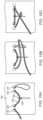
- FIG. 1shows an expandable device and an actuation wire in accordance with various aspects of the present disclosure.
- FIG. 2shows another expandable device and an actuation wire in accordance with various aspects of the present disclosure.
- FIG. 3shows yet another expandable device and an actuation wire in accordance with various aspects of the present disclosure.
- FIGS. 4 A-Eshows side view illustrations of expandable device angulation relative to a target location in accordance with various aspects of the present disclosure.
- FIG. 5 Ashows a front view of an expandable device and an actuation wire in accordance with various aspects of the present disclosure.
- FIG. 5 Bshows a side view of the expandable device and the actuation wire, shown in FIG. 5 A , in accordance with various aspects of the present disclosure.
- FIG. 6 Ashows a front view of another expandable device and an actuation wire in accordance with various aspects of the present disclosure.
- FIG. 6 Bshows a side view of the expandable device and the actuation wire, shown in FIG. 6 A , in accordance with various aspects of the present disclosure.
- FIG. 7 Ashows a front view of yet another expandable device and an actuation wire in accordance with various aspects of the present disclosure.
- FIG. 7 Bshows a side view of the expandable device and the actuation wire, shown in FIG. 7 A , in accordance with various aspects of the present disclosure.
- FIG. 8shows an actuation wire and tether attachment to an expandable device in accordance with various aspects of the present disclosure.
- FIG. 9 A-Dshow a tether attachment arrangement in accordance with various aspects of the present disclosure.
- FIG. 10 A-Cshow another tether attachment arrangement in accordance with various aspects of the present disclosure.
- Various aspects of the present disclosureare directed toward apparatuses, systems, and methods that include an expandable device that may be used in treatment of the vasculature.
- the expandable deviceis delivered to the vasculature using a delivery system.
- the delivery systemmay be configured to position and/or steer the expandable device for accurate placement in the vasculature.
- the expandable devicemay include a flow lumen between ends of the expandable device.
- the delivery systemmay be configured to arrange the expandable device such that one or both of the ends of the expandable device is perpendicular to a portion of the vasculature.
- the expandable devices described hereinmay be substantially cylindrical or include a bifurcation. Further, the expandable devices may be configured to conform to the vasculature into which the expandable device is implanted, low-profile in order to enable delivery thereof using a minimally invasive procedure (e.g., transcatheter), and withstand forces and other stresses that occur once implanted in the vasculature.
- a minimally invasive proceduree.g., transcatheter
- FIG. 1shows an expandable device 100 and an actuation wire 102 in accordance with various aspects of the present disclosure.
- the expandable device 100is releasably coupled to a delivery system for delivery of the expandable device 100 to a target location within a patient's vasculature.
- the delivery systemmay include a catheter 104 that includes a leading end 106 and a trailing end (not shown in FIG. 1 ).
- the expandable device 100may be arranged near the leading end 106 of the catheter 104 .
- the catheter 104may extend through a lumen of the expandable device 100 toward and past a proximal end 108 of the expandable device 100 .
- the catheter 104may also include a tip (not shown) at the leading end 106 .
- the expandable device 100may include a proximal end 108 , a distal end 110 , and a flow lumen extending therebetween.
- the proximal end 108 of the expandable device 100may be considered the end of the expandable device 100 that is closest to the target location within the patient's vasculature.
- the actuation wire 102is coupled to the expandable device 100 at one or more locations thereon. As shown in FIG. 1 , the actuation wire 102 is attached adjacent to or near the proximal end 108 of the expandable device 100 and accessible to a user of the delivery system.
- the actuation wire 102is coupled to the expandable device 100 via at least one tether 112 .
- the tether 112may be arranged through a portion of the expandable device 100 and through the actuation wire 102 to couple the actuation wire 102 to the expandable device 100 .
- the at least one tether 112is arranged through the expandable device 100 near or adjacent to the proximal end 108 of the expandable device 100 .
- the at least one tether 112may be a single tether, as shown in FIG. 1 .
- the actuation wire 102is configured to steer the expandable device 100 during delivery thereof.
- the actuation wire 102may include a stiffness such that a user operating the delivery system may apply force to the actuation wire 102 and bidirectionally steer (e.g., proximally and distally relative to the target location within the patient's vasculature) the expandable device 100 .
- the actuation wire 102may have a stiffness that is greater than a stiffness of the tether 112 .
- the stiffness of the actuation wire 102 and/or the location to which the actuation wire 102 is coupled to the expandable device 100may facilitate deploying and arranging the expandable device 100 relative to the target location within the patient's vasculature.
- the expandable device 100may be configured to deploy at a tortious vessel having a curvature with at least one inflection point.
- the actuation wire 102is configured to maintain the proximal end 108 of the expandable device 100 approximately perpendicular to the inflection point in the curvature of the tortious vessel during delivery of the expandable device 100 .
- the actuation wire 102may be uncoupled or released from the actuation wire 102 subsequent to the expandable device 100 being positioned and deployed at the target location within the patient's vasculature and removed from the patient.
- the tether 112is configured to remain coupled or threaded through the expandable device 100 after the actuation wire 102 is released or uncoupled from the expandable device 100 (e.g., as shown in further detail in FIG. 8 ).
- the tether 112may be formed from a bio-absorbable material that dissolves to release or uncouple the actuation wire 102 from the expandable device 100 .
- FIG. 2shows another expandable device 200 and an actuation wire 202 in accordance with various aspects of the present disclosure.
- the expandable device 200may be releasably coupled to a delivery system.
- the delivery systemmay include a catheter 204 that includes a leading end 206 and a trailing end (not shown in FIG. 2 ).
- the expandable device 200may be arranged near the leading end 206 of the catheter 204 .
- the delivery systemmay be configured to deliver the expandable device 200 to a target location within a patient's vasculature.
- the expandable device 200may be configured to deploy at a tortious vessel having a curvature with at least one inflection point.
- the delivery systemmay include the actuation wire 202 configured to maintain a proximal end 208 (or distal end 210 ) of the expandable device 200 approximately perpendicular to the inflection point in the curvature of the tortious vessel during delivery of the expandable device 200 .
- the actuation wire 202(and accessible to a user of the delivery system), for example, is configured to steer the expandable device 200 during delivery thereof, and is releasably coupled to the expandable device 200 via at least one tether 212 .
- the tether 212may be arranged through a portion of the expandable device 200 and through the actuation wire 202 to couple the actuation wire 202 to the expandable device 200 .
- the at least one tether 212is arranged through the expandable device 200 near or adjacent to the proximal end 208 of the expandable device 200 .
- the tether 212is configured to remain coupled or threaded through the expandable device 200 after the actuation wire 102 is released or uncoupled from the expandable device 200 (e.g., as shown in further detail in FIG. 8 ) or the tether 212 may be configured to be removed or unthreaded from the expandable device 200 after the actuation wire 202 is released or uncoupled from the expandable device 200 (e.g., as shown in further detail in FIGS. 9 A-D and FIGS. 10 A-C ).
- the actuation wire 202may be arranged through a sleeve 214 that is attached to an exterior portion of the expandable device 200 .
- the expandable device 200may include a graft component and one or more stent components (e.g., as shown in further detail with reference to FIG. 5 ).
- the sleeve 214may be formed of a similar material or the same material as the graft component of the expandable device 200 .
- the sleeve 214may include a lumen through which the actuation wire 202 is arranged.
- the sleeve 214is an enclosed structure which forms the lumen, or the sleeve 214 is a layer of graft material that forms a lumen between the sleeve 214 and the expandable device 200 .
- the sleeve 214may facilitate the actuation wire 202 steering the expandable device 200 .
- the sleeve 214may prevent traumatic interaction between the actuation wire 202 and a vessel wall.
- the sleeve 214may enhance the connection between the actuation wire 202 and the expandable device 200 when a user applies force or tension to the actuation wire 202 .
- the sleeve 214has a length similar to a length of the expandable device 200 . In other instances, the sleeve 214 may have a shorter length than the expandable device 200 or a longer length than the expandable device.
- the actuation wire 202may include a stiffness such that a user operating the delivery system may apply force to the actuation wire 202 and bidirectionally steer (e.g., proximally and distally relative to the target location within the patient's vasculature) the expandable device 200 .
- the actuation wire 202may have a stiffness that is greater than a stiffness of the tether 212 .
- the stiffness of the actuation wire 202 and/or the location to which the actuation wire 202 is coupled to the expandable device 200may facilitate deploying and arranging the expandable device 200 relative to the target location within the patient's vasculature.
- FIG. 3shows yet another expandable device 300 and an actuation wire 302 a - c in accordance with various aspects of the present disclosure.
- the actuation wire 302 a - cis shown arranged along the expandable device 300 in three different patterns.
- the patterns of the actuation wire 302 a - c shown in FIG. 3may facilitate the ability of the actuation wire 302 a - c to steer the expandable device by distributing forces that result from a user applying force or tension to the actuation wire 302 a - c to steer the expandable device 300 (e.g., as described above in detail with reference to FIGS. 1 - 2 ).
- the actuation wire 302 a - cmay be attached to the expandable device 300 via a tether 304 a - c .
- the tether 304 a - cmay be arranged through the actuation wire 302 a - c at any portion along a length thereof that is in contact with the expandable device 300 .
- the illustrative expandable device 300 and actuation wire 302 a - c shown in FIG. 3is not intended to suggest any limitation as to the scope of use or functionality of embodiments of the discussed throughout this disclosure. Neither should the illustrative expandable device 300 and actuation wire 302 be interpreted as having any dependency or requirement related to any single component or combination of components illustrated therein.
- the illustrative actuation wire 302 a - cmay include a stiffness and bidirectional steering as described above with reference to FIGS. 1 - 2 .
- any one or more of the components depicted in FIG. 3can be integrated with various ones of the other components depicted therein (and/or components not illustrated).
- the patterns of the actuation wire 302 a - cmay be used in connection with the actuation wires 102 , 202 shown in FIGS. 1 - 2 .
- FIGS. 4 A-Eshows side view illustrations of expandable device angulation relative to a target location 400 a - e in accordance with various aspects of the present disclosure.
- FIGS. 4 A-Eshow a side profile of a leading (or proximal) end 400 a - e of an expandable device, consistent with various aspects of the present disclosure.
- the target location 400 a - emay be at a tortious vessel of a patient.
- the target location 400 a - e into which the expandable device is implantedmay have angulation (e.g., a curvature with at least one inflection point 404 a - e ).
- the target location 400 a - emay be an angulated abdominal aortic aneurism (AAA).
- AAAabdominal aortic aneurism
- one of the ends 402 a - e of the expandable devicemay be deployed perpendicular to the inflection point in the curvature of the tortious vessel during delivery of the expandable device.
- Non-perpendicularitymay negatively affect the ability of the expandable device to seal against the target location 400 a - e .
- FIG. 4 Ashows the leading (or proximal) end 402 a deployed perpendicular to the inflection point 404 a .
- perpendicularity of the expandable devicemay be a function of device flatness, angulation, and rotational alignment.
- FIG. 4 Bshows the leading (or proximal) end 402 b of an expandable device angled relative to the inflection point 404 b of the target location 400 b .
- FIG. 4 Cshows the leading (or proximal) end 402 c of an expandable device rotated relative to the inflection point 404 c of the target location 400 c .
- FIG. 4 Dshows the leading (or proximal) end 402 d of an expandable device deformed relative to the inflection point 404 b of the target location 400 d .
- FIG. 4 Eshows the leading (or proximal) end 402 e of an expandable device deformed or flat, rotated, and angled relative to the inflection point 404 e of the target location 400 e.
- Device deployment and performancecan be enhanced by steering the device to an appropriate location while maintaining one of the ends of the expandable device perpendicular to the target location 400 a - e (e.g., curvature of a vessel with at least one inflection point 404 a - e ) during and after deployment.
- the actuation wires and arrangements thereof discussed hereinfacilitate maintaining the expandable device perpendicular during and after deployment (as shown in FIG. 4 A ) and mitigate against non-perpendicular, angled, or flat deployment (as shown in FIGS. 4 B-E ).
- FIGS. 5 A-Bshow a side view and a front view of an expandable device 500 and an actuation wire 502 in accordance with various aspects of the present disclosure.
- the expandable device 500may include a graft component 504 and one or more stent components 506 .
- the delivery systemmay include a catheter 508 that includes a leading end 510 and a trailing end (not shown in FIGS. 5 A-B ).
- the expandable device 500may be arranged near the leading end 510 of the catheter 508 .
- the expandable device 500may include a proximal end 512 , a distal end 514 , and a flow lumen extending therebetween.
- the proximal end 512 of the expandable device 500is considered the end of the expandable device 500 closest to the target location within the patient's vasculature.
- the actuation wire 502is configured to releasably couple the expandable device 500 to the delivery system for delivery of the expandable device 500 to a target location within a patient's vasculature and accessible to a user of the delivery system.
- the actuation wire 502is coupled to the expandable device 500 at one or more locations thereon. As shown in FIG. 5 B , the actuation wire 502 bifurcates to form a first branch 516 and a second branch 518 . The first branch 516 and the second branch 518 are coupled to the expandable device 500 at the two or more locations thereon. The first branch 516 and the second branch 518 are coupled to the expandable device 500 near the proximal end 512 . In addition, the actuation wire 502 is configured to steer the expandable device 500 during delivery thereof. The first branch 516 and the second branch 518 may facilitate the ability of the actuation wire 502 to steer the expandable device 500 by distributing forces that result from a user manipulating or applying force to the actuation wire 502 to steer the expandable device 500 .
- one of the proximal end 512 and the distal end 514 of the expandable device 500may be deployed perpendicular to a portion of the target location.
- the target locationmay be tortious vessel, which may include one or more inflection points in the curvature of the tortious vessel.
- perpendicularity of an end of the expandable device 500is enhanced by the actuation wire 502 being configured to steer the expandable device 500 to the target location while maintaining one of the ends (the proximal end 512 or the distal end 514 ) of the expandable device 500 perpendicular to the target location.
- the first branch 516 and the second branch 518may facilitate maintaining the expandable device perpendicular during and after deployment (as shown in FIG. 4 A ) and mitigate against non-perpendicular deployment (as shown in FIGS. 4 B-E ).
- the first branch 516 and the second branch 518may distribute forces applied to the actuation wire 502 in steering the expandable device 500 .
- a user operating the delivery systemmay apply force to the actuation wire 500 and bidirectionally steer (e.g., proximally and distally relative to the target location within the patient's vasculature) the expandable device 500 .
- the actuation wire 502is configured to remain in tension through a length thereof when force is applied to the actuation wire 502 by the user.
- the actuation wire 502may have a stiffness such that the actuation wire 502 does not become relaxed or slacked in response to the user applying force (e.g., tension) to steer the expandable device 500 proximally and distally.
- forcee.g., tension
- the actuation wire 502is coupled to the expandable device 500 via an adhesive (e.g., fluorinated ethylene propylene (FEP)).
- FEPfluorinated ethylene propylene
- Each of the first branch 516 and the second branch 518are releasably adhered to the expandable device 500 along any portion thereof.
- portions of the actuation wire 502are arranged through expandable device 500 . The portions may be the first branch 516 and the second branch 518 threaded through the graft component 504 . After the user has steered the expandable device 500 to a desired location and after deployment thereof, the actuation wire 502 may be released from the expandable device 500 and removed from the patient.
- actuation wire 502is directly attached to the expandable device 500 , and when force applied by the user, in excess of the force used to steer, may release the actuation wire 502 .
- Friction between the target location (e.g., vessel wall) and the expandable device 500may allow user to apply a greater force or tension to the actuation wire 502 than during steering to release the actuation wire 502 .
- the delivery systemmay include one or more tethers (not shown) arranged through a portion of the expandable device 500 and arranged through the actuation wire 502 .
- the tethers(e.g., as shown in FIGS. 8 - 9 ) are configured to couple the actuation wire 502 to the expandable device 500 .
- One of the tethersis arranged through the first branch 516
- a second of the two tethersis arranged through the second branch 518 .
- the tethersmay be arranged through the first branch 516 and the second branch 518 of the actuation wire 502 adjacent the proximal end 512 of the expandable device 500 .
- the tethersmay be configured to uncouple and release from the expandable device 500 in response to force or tension applied to the tethers after delivery of the expandable device.
- the tethersmay break in response to the force or tension (and remain with the expandable device 500 after release of the actuation wire 502 ) or the tethers may unthread and be removed with the actuation wire 502 (e.g., as show in FIGS. 9 A-D and FIGS. 10 A-C ).
- FIGS. 6 A-Bshow a side view and a front view of an expandable device 600 and an actuation wire 602 in accordance with various aspects of the present disclosure.
- the expandable device 600may include a graft component 604 and one or more stent components 606 .
- the delivery systemmay include a catheter 608 with a portion 610 of the catheter 608 arranged through the expandable device 600 .
- the actuation wire 602may be configured to releasably couple the expandable device 600 to the delivery system for delivery of the expandable device 600 to a target location within a patient's vasculature.
- the expandable device 600may include a proximal end 612 , a distal end 614 , and a flow lumen extending therebetween.
- the actuation wire 602is coupled to the expandable device 600 at one or more locations thereon and accessible to a user of the delivery system.
- the actuation wire 602may be coupled to the expandable device 600 by at least one tether 616 .
- the at least one tether 616 and the actuation wire 602may form a y-shaped structure.
- the least one tether 616is configured to couple the actuation wire 602 to the two or more locations on the expandable device 602 .
- the least one tether 616is secured to the actuation wire 602 or arranged through the actuation wire 602 (e.g., as shown in FIG. 8 ).
- the at least one tether 616is a plurality of tethers (e.g., two tethers) coupled to the actuation wire 602 .
- the least one tether 616(or plurality of tethers) is coupled to the expandable device 600 adjacent the proximal end 612 thereof.
- the actuation wire 602is configured to steer the expandable device 600 during delivery thereof.
- the at least one tether 616 being coupled to two locations on the expandable device 600may facilitate the ability of the actuation wire 602 to steer the expandable device 600 by distributing forces that result from a user applying force or tension to the actuation wire 602 to steer the expandable device 600 .
- one of the proximal end 612 and the distal end 614 of the expandable device 600are deployed perpendicular to a portion of the target location (e.g., a tortious vessel).
- Perpendicularity of the expandable device 600may be enhanced by the actuation wire 602 being configured to steer the expandable device 600 to the target location while maintaining one of the ends (the proximal end 612 or the distal end 614 ) of the expandable device 600 perpendicular to the target location. Further, a user operating the delivery system may apply force to the actuation wire 600 and bidirectionally steer (e.g., proximally and distally relative to the target location within the patient's vasculature) the expandable device 600 .
- the actuation wire 602may be configured to remain in tension through a length thereof when tension is applied to the actuation wire 602 by the user.
- the actuation wire 602may be released from the expandable device 600 and removed from the patient.
- the force or tension applied to at least one tether 616causes the tether 616 to uncouple from the expandable device 600 .
- FIGS. 7 A-Bshow a side view and a front view of an expandable device 700 and an actuation wire 702 in accordance with various aspects of the present disclosure.
- the expandable device 700may include a graft component 704 and one or more stent components 706 .
- the delivery systemmay include a catheter 708 with a leading end 710 of the catheter 708 arranged near an end of the expandable device 700 .
- the actuation wire 702may be configured to releasably couple the expandable device 700 to the delivery system for delivery of the expandable device 700 to a target location within a patient's vasculature.
- the expandable device 700may include a proximal end 712 , a distal end 714 , and a flow lumen extending therebetween.
- the actuation wire 702is configured to steer the expandable device 700 and is accessible to a user of the delivery system. In certain instances, one of the proximal end 712 and the distal end 714 of the expandable device 700 are deployed perpendicular to a portion of the target location (e.g., a tortious vessel). Further, a user operating the delivery system can apply force to the actuation wire 702 and bidirectionally steer (e.g., proximally and distally relative to the target location within the patient's vasculature) the expandable device 700 .
- the actuation wire 702may be configured to remain in tension through a length thereof when tension is applied to the actuation wire 702 by the user.
- At least one tether 716may be coupled to two (or more) locations 728 , 730 on the expandable device 700 to facilitate the ability of the actuation wire 702 to steer the expandable device 700 by distributing forces that result from a user applying force to the actuation wire 702 to steer the expandable device 700 .
- tethers 716 , 718are configured to couple the actuation wire 702 to the expandable device 700 .
- the tethers 716 , 718are arranged through the expandable device 700 (e.g., through the graft component 704 ) at one or locations thereon.
- the tethers 716 , 718may be arranged through the expandable device 700 near the proximal end 712 .
- the tethers 716 , 718may extend from the proximal end 712 of the expandable device 700 and may also be accessible to the user.
- the at least one tethers 716 , 718 and the actuation wire 702may form a y-shaped structure.
- the tethers 716 , 718may each include two portions.
- first portions 720 , 722 of the tethers 716 , 718are arranged internal to the expandable device and may be accessible to the user, and second portions 724 , 726 of the tethers 716 , 718 are arranged between the eyelet 720 and an eyelet 720 of the actuation wire 702 .
- the first portions 720 , 722 and the second portions 724 , 726 of the tethers 716 , 718are distinct threads attached or knotted together at the locations 728 , 730 on the expandable device 700 .
- the first portions 720 , 722 and/or the second portions 724 , 726may be thread through the graft component 704 .
- the first portions 720 , 722 and the second portions 724 , 726 of the tethers 716 , 718are integral with one another and are thread through the graft component 704 at the locations 728 , 730 on the expandable device 700 .
- the actuation wire 702may be released from the expandable device 700 and removed from the patient.
- the usermay apply tension to ends of the tethers 716 , 718 to unthread the tethers 716 , 718 from the expandable device 700 and through the eyelet 720 .
- the first portions 720 , 722 and the second portions 724 , 726 of the tethers 716 , 718are integral with one another and are concurrently releasable by tensioning the ends of the tethers 716 , 718 .
- first portions 720 , 722 and the second portions 724 , 726 of the tethers 716 , 718are attached or knotted together, tension is applied to the first portions 720 , 722 of the tethers 716 , 718 for release thereof.
- the first portions 720 , 722may release from the second portions 724 , 726 , and the first portions 720 , 722 of the tethers 716 , 718 may be removed from the expandable device 700 .
- the expandable device 700 shown in FIGS. 7 A-Bis not intended to suggest any limitation as to the scope of use or functionality of embodiments of the disclosure disclosed throughout this document. Neither should the illustrative prosthesis 200 be interpreted as having any dependency or requirement related to any single component or combination of components illustrated therein.
- the illustrative expandable device 700may include additional components such as described in further detail with reference to FIGS. 1 - 6 and 8 - 9 .
- any one or more of the components depicted in FIGS. 7 A-Bcan be, in embodiments, integrated with various ones of the other components depicted therein (and/or components not illustrated).
- FIG. 8shows an actuation wire 802 and tether 804 attachment to an expandable device 800 in accordance with various aspects of the present disclosure.
- the actuation wire 802may include an eyelet 806 arranged at an end thereof.
- the tether 804may be threaded through the eyelet 806 to releasably couple the expandable device 800 to a delivery system.
- the tether 804may also be threaded through the expandable device 800 to releasably couple the expandable device 800 to the delivery system. In other instances, the tether 804 is directly attached to the expandable device 800 via an adhesive. In addition, the actuation wire 802 may have a stiffness greater than a stiffness of the tether 804 as is described in further detail above.
- FIG. 9 A-Dshow a tether attachment 902 arrangement in accordance with various aspects of the present disclosure.
- the tether attachment 902may be threaded through an expandable medical device 900 at two locations 904 .
- the tether attachment 902may include a looped end 906 .
- FIG. 9 Bthe tether attachment 902 is threaded through the looped end 906 .
- FIG. 9 Cthe tether attachment 902 is threaded back through the looped end 906 .
- the tether attachment 902is pulled tight to form a releasable slip knot.
- the tether attachment 902may be used to couple an expandable device to an actuation wire as discussed herein.
- FIG. 10 A-Cshow a tether attachment 1002 arrangement in accordance with various aspects of the present disclosure.
- the tether attachment 1002may be threaded through an expandable medical device 1000 at four locations 1004 .
- the tether attachment 1002is threaded through the four locations 1004 .
- the tether attachment 1002may include a looped end 1010 .
- the tether attachment 1002may be used to couple an expandable device to an actuation wire 1006 as discussed herein.
- the tether attachment 1002is arranged through an eyelet 1008 of the actuation wire 1006 .
- the tether attachment 1002is threaded through the looped end 1010 , and then back therethrough.
- the tether attachment 1010is pulled tight to form a releasable slip not.
- Other release mechanismsmay be used to couple an actuation wire to an expandable medical device as discussed herein.
- actuation wires discussed hereinmay be formed from metallic, polymeric or natural materials such as stainless steels, cobalt-chromium alloys and nitinol. Further, actuation wires can also be formed from high strength polymer fibers such as ultra high molecular weight polyethylene fibers (e.g., SpectraTM, Dyneema PurityTM, etc.) or aramid fibers (e.g., TechnoraTM, etc.).
- high strength polymer fiberssuch as ultra high molecular weight polyethylene fibers (e.g., SpectraTM, Dyneema PurityTM, etc.) or aramid fibers (e.g., TechnoraTM, etc.).
- the graft componentsmay be made up of any material which is suitable for use as a graft in the chosen body lumen and being resistant to expansion as discussed herein.
- the graft componentsmay be composed of the same or different materials.
- the graft componentsmay include multiple layers of material that can be the same material or different material. In one embodiment, said materials can be used in combination and assembled together to comprise a graft.
- the graft materials used in a stent graftcan be extruded, coated or formed from wrapped films, or a combination thereof. Polymers, biodegradable and natural materials can be used for specific applications.
- synthetic polymersinclude, but are not limited to, nylon, polyacrylamide, polycarbonate, polyformaldehyde, polymethylmethacrylate, polytetrafluoroethylene, polytrifluorochlorethylene, polyvinylchloride, polyurethane, elastomeric organosilicon polymers, polyethylene, polypropylene, polyurethane, polyglycolic acid, polyesters, polyamides, their mixtures, blends and copolymers are suitable as a graft material.
- said graftis made from a class of polyesters such as polyethylene terephthalate including DACRON® and MYLAR® and polyaramids such as KEVLAR®, polyfluorocarbons such as polytetrafluoroethylene (PTFE) with and without copolymerized hexafluoropropylene (TEFLON® or GORE-TEX®), and porous or nonporous polyurethanes.
- said graftcomprises expanded fluorocarbon polymers (especially PTFE) materials described in British. Pat. No. 1,355,373; 1,506,432; or 1,506,432 or in U.S. Pat. Nos.
- PTFEpolytetrafluoroethylene
- FEPfluorinated ethylene propylene
- TFEtetrafluoroethylene
- PFAperfluoro(propyl vinyl ether)
- PCTFEpolychlorotrifluoroethylene
- ECTFEethylene-chlorotrifluoroethylene
- ETFEethylene-tetrafluoroethylene
- PVDFpolyvinylidene fluoride
- PVFpolyvinyfluoride
- said graftcomprises a combination of said materials listed above.
- said graftis substantially impermeable to bodily fluids.
- Said substantially impermeable graftcan be made from materials that are substantially impermeable to bodily fluids or can be constructed from permeable materials treated or manufactured to be substantially impermeable to bodily fluids (e.g. by layering different types of materials described above or known in the art).
- said outermost tubecomprises ePTFE.
- said innermost tubecomprises ePTFE.
- said innermost and outermost tubecomprises ePTFE film that has been wrapped into a tube.
- said secondary stentis covered with any of the material disclosed herein or known in the art.
- the secondary stent coveringcomprises ePTFE.
- graft materialsinclude, but are not limited to, vinylidinefluoride/hexafluoropropylene hexafluoropropylene (HFP), tetrafluoroethylene (TFE), vinylidenefluoride, 1-hydropentafluoropropylene, perfluoro(m ethyl vinyl ether), chlorotrifluoroethylene (CTFE), pentafluoropropene, trifluoroethylene, hexafluoroacetone, hexafluoroisobutylene, fluorinated poly(ethylene-co-propylene (FPEP), poly(hexafluoropropene) (PHFP), poly(chlorotrifluoroethylene) (PCTFE), poly(vinylidene fluoride (PVDF), poly(vinylidene fluoride-co-tetrafluoroethylene) (PVDF-TFE), poly(vinylidene fluoride-co-hexafluoropropene
- Additional polyfluorocopolymersinclude tetrafluoroethylene (TFE)/perfluoroalkylvinylether (PAVE).
- PAVEcan be perfluoromethylvinyl ether (PMVE), perfluoroethylvinylether (PEVE), or perfluoropropylvinylether (PPVE), as described in U.S. Publication 2006/0198866 and U.S. Pat. No. 7,049,380, both of which are incorporated by reference herein for all purposes in their entireties.
- polymers and copolymersinclude, polylactide, polycaprolacton-glycolide, polyorthoesters, polyanhydrides; poly-aminoacids; polysaccharides; polyphosphazenes; poly(ether-ester) copolymers, e.g., PEO-PLLA, or blends thereof, polydimethyl-siolxane; poly(ethylene-vingylacetate); acrylate based polymers or copolymers, e.g., poly(hydroxyethyl methylmethacrylate, polyvinyl pyrrolidinone; fluorinated polymers such as polytetrafluoroethylene; cellulose esters and any polymer and copolymers described in U.S. Publication 2004/0063805, incorporated by reference herein in its entity.
- the graft componentsmay be attached to the self-expanding stent elements by using a coupling member that is generally a flat ribbon or tape having at least one generally flat surface.
- the tape memberis made from expanded PTFE (ePTFE) coated with an adhesive.
- the adhesivemay be a thermoplastic adhesive.
- the thermoplastic adhesivemay be fluorinated ethylene propylene (FEP). More specifically, an FEP-coated side of the ePTFE may face toward and contacts an exterior surface of the self-expanding stent and graft component, thus attaching the self-expanding stent to the graft component.
- FEPfluorinated ethylene propylene
- the stent component(s) discussed hereincan be fabricated from a variety of biocompatible materials. These materials may include 316 L stainless steel, cobalt-chromium-nickel-molybdenum-iron alloy (“cobalt-chromium”), other cobalt alloys such as L605, tantalum, Nitinol, or other biocompatible metals.
- cobalt-chromiumcobalt-chromium-nickel-molybdenum-iron alloy
- other cobalt alloyssuch as L605, tantalum, Nitinol, or other biocompatible metals.
- the stent (and graft)may be self-expanding.
- the prosthesismay be balloon expandable.
- the stent component(s) discussed hereinmay be constructed from a reasonably high strength material, i.e., one which is resistant to plastic deformation when stressed.
- the stent component(s)comprise a wire which is helically wound around a mandrel having pins arranged thereon so that the helical turns and undulations can be formed simultaneously. Other constructions may also be used.
- the stent component(s)are made from a super-elastic alloy.
- super-elastic alloyssuch as nitinol are used in stents. See for example, U.S. Pat. No. 4,503,569, to Dotter; U.S. Pat. No.
- Nitinolvariously metallic, super elastic alloys, such as Nitinol, are suitable for use in the stent component(s). Primary requirements of the materials are that they be suitably springy even when fashioned into very thin sheets or small diameter wires.
- Various stainless steelswhich have been physically, chemically, and otherwise treated to produce high springiness are suitable as are other metal alloys such as cobalt chrome alloys (e.g., ELGILOY®), platinum/tungsten alloys, and especially the nickel-titanium alloys generically known as “nitinol”.
Landscapes
- Health & Medical Sciences (AREA)
- Engineering & Computer Science (AREA)
- Biomedical Technology (AREA)
- Heart & Thoracic Surgery (AREA)
- Public Health (AREA)
- Transplantation (AREA)
- Cardiology (AREA)
- Veterinary Medicine (AREA)
- Oral & Maxillofacial Surgery (AREA)
- Vascular Medicine (AREA)
- Life Sciences & Earth Sciences (AREA)
- Animal Behavior & Ethology (AREA)
- General Health & Medical Sciences (AREA)
- Gastroenterology & Hepatology (AREA)
- Pulmonology (AREA)
- Media Introduction/Drainage Providing Device (AREA)
- Prostheses (AREA)
- Surgical Instruments (AREA)
Abstract
Description
Claims (17)
Priority Applications (2)
| Application Number | Priority Date | Filing Date | Title |
|---|---|---|---|
| US16/562,669US12310869B2 (en) | 2017-03-08 | 2019-09-06 | Steering wire attach for angulation |
| US19/190,216US20250248832A1 (en) | 2017-03-08 | 2025-04-25 | Steering wire attach for angulation |
Applications Claiming Priority (3)
| Application Number | Priority Date | Filing Date | Title |
|---|---|---|---|
| US201762468618P | 2017-03-08 | 2017-03-08 | |
| PCT/US2018/021442WO2018165358A1 (en) | 2017-03-08 | 2018-03-08 | Steering wire attach for angulation |
| US16/562,669US12310869B2 (en) | 2017-03-08 | 2019-09-06 | Steering wire attach for angulation |
Related Parent Applications (1)
| Application Number | Title | Priority Date | Filing Date |
|---|---|---|---|
| PCT/US2018/021442ContinuationWO2018165358A1 (en) | 2017-03-08 | 2018-03-08 | Steering wire attach for angulation |
Related Child Applications (1)
| Application Number | Title | Priority Date | Filing Date |
|---|---|---|---|
| US19/190,216ContinuationUS20250248832A1 (en) | 2017-03-08 | 2025-04-25 | Steering wire attach for angulation |
Publications (2)
| Publication Number | Publication Date |
|---|---|
| US20190388256A1 US20190388256A1 (en) | 2019-12-26 |
| US12310869B2true US12310869B2 (en) | 2025-05-27 |
Family
ID=62486621
Family Applications (2)
| Application Number | Title | Priority Date | Filing Date |
|---|---|---|---|
| US16/562,669Active2041-10-09US12310869B2 (en) | 2017-03-08 | 2019-09-06 | Steering wire attach for angulation |
| US19/190,216PendingUS20250248832A1 (en) | 2017-03-08 | 2025-04-25 | Steering wire attach for angulation |
Family Applications After (1)
| Application Number | Title | Priority Date | Filing Date |
|---|---|---|---|
| US19/190,216PendingUS20250248832A1 (en) | 2017-03-08 | 2025-04-25 | Steering wire attach for angulation |
Country Status (7)
| Country | Link |
|---|---|
| US (2) | US12310869B2 (en) |
| EP (1) | EP3592285A1 (en) |
| JP (2) | JP6883115B2 (en) |
| CN (1) | CN110650708B (en) |
| AU (1) | AU2018230960B2 (en) |
| CA (1) | CA3055567C (en) |
| WO (1) | WO2018165358A1 (en) |
Families Citing this family (26)
| Publication number | Priority date | Publication date | Assignee | Title |
|---|---|---|---|---|
| US9877858B2 (en) | 2011-11-14 | 2018-01-30 | W. L. Gore & Associates, Inc. | External steerable fiber for use in endoluminal deployment of expandable devices |
| US9782282B2 (en) | 2011-11-14 | 2017-10-10 | W. L. Gore & Associates, Inc. | External steerable fiber for use in endoluminal deployment of expandable devices |
| US9375308B2 (en) | 2012-03-13 | 2016-06-28 | W. L. Gore & Associates, Inc. | External steerable fiber for use in endoluminal deployment of expandable devices |
| CA3055567C (en) | 2017-03-08 | 2021-11-23 | W. L. Gore & Associates, Inc. | Steering wire attach for angulation |
| WO2019195860A2 (en) | 2018-04-04 | 2019-10-10 | Vdyne, Llc | Devices and methods for anchoring transcatheter heart valve |
| AU2018439076B2 (en) | 2018-08-31 | 2022-07-07 | W. L. Gore & Associates, Inc. | Apparatus, system, and method for steering an implantable medical device |
| US10595994B1 (en) | 2018-09-20 | 2020-03-24 | Vdyne, Llc | Side-delivered transcatheter heart valve replacement |
| US11344413B2 (en) | 2018-09-20 | 2022-05-31 | Vdyne, Inc. | Transcatheter deliverable prosthetic heart valves and methods of delivery |
| US10321995B1 (en) | 2018-09-20 | 2019-06-18 | Vdyne, Llc | Orthogonally delivered transcatheter heart valve replacement |
| US11071627B2 (en) | 2018-10-18 | 2021-07-27 | Vdyne, Inc. | Orthogonally delivered transcatheter heart valve frame for valve in valve prosthesis |
| US11278437B2 (en) | 2018-12-08 | 2022-03-22 | Vdyne, Inc. | Compression capable annular frames for side delivery of transcatheter heart valve replacement |
| US12186187B2 (en) | 2018-09-20 | 2025-01-07 | Vdyne, Inc. | Transcatheter deliverable prosthetic heart valves and methods of delivery |
| US11109969B2 (en) | 2018-10-22 | 2021-09-07 | Vdyne, Inc. | Guidewire delivery of transcatheter heart valve |
| US11253359B2 (en) | 2018-12-20 | 2022-02-22 | Vdyne, Inc. | Proximal tab for side-delivered transcatheter heart valves and methods of delivery |
| WO2020146842A1 (en) | 2019-01-10 | 2020-07-16 | Vdyne, Llc | Anchor hook for side-delivery transcatheter heart valve prosthesis |
| US11185409B2 (en) | 2019-01-26 | 2021-11-30 | Vdyne, Inc. | Collapsible inner flow control component for side-delivered transcatheter heart valve prosthesis |
| US11273032B2 (en) | 2019-01-26 | 2022-03-15 | Vdyne, Inc. | Collapsible inner flow control component for side-deliverable transcatheter heart valve prosthesis |
| WO2020181154A2 (en) | 2019-03-05 | 2020-09-10 | Vdyne, Inc. | Tricuspid regurgitation control devices for orthogonal transcatheter heart valve prosthesis |
| US11076956B2 (en) | 2019-03-14 | 2021-08-03 | Vdyne, Inc. | Proximal, distal, and anterior anchoring tabs for side-delivered transcatheter mitral valve prosthesis |
| US11173027B2 (en) | 2019-03-14 | 2021-11-16 | Vdyne, Inc. | Side-deliverable transcatheter prosthetic valves and methods for delivering and anchoring the same |
| CA3138875A1 (en) | 2019-05-04 | 2020-11-12 | Vdyne, Inc. | Cinch device and method for deployment of a side-delivered prosthetic heart valve in a native annulus |
| EP4480458A3 (en) | 2019-08-20 | 2025-04-09 | Vdyne, Inc. | Delivery devices for side-deliverable transcatheter prosthetic valves |
| CN120531525A (en) | 2019-08-26 | 2025-08-26 | 维迪内股份有限公司 | Laterally deliverable transcatheter prosthetic valve and method for its delivery and anchoring |
| US11234813B2 (en) | 2020-01-17 | 2022-02-01 | Vdyne, Inc. | Ventricular stability elements for side-deliverable prosthetic heart valves and methods of delivery |
| CN113876467B (en)* | 2021-12-08 | 2022-04-15 | 上海微创心脉医疗科技(集团)股份有限公司 | stent graft |
| CN118948490A (en)* | 2024-10-17 | 2024-11-15 | 上海宏普医疗器械有限公司 | A sutureless dialysis artificial blood vessel |
Citations (287)
| Publication number | Priority date | Publication date | Assignee | Title |
|---|---|---|---|---|
| US1355373A (en) | 1920-08-09 | 1920-10-12 | White Dell Joseph | Lock-nut |
| US1506432A (en) | 1923-03-26 | 1924-08-26 | Harry B Kimmel | Fire pot |
| US1851314A (en) | 1929-05-25 | 1932-03-29 | Belding Heminway Company | Spool for thread |
| US3625451A (en) | 1969-09-11 | 1971-12-07 | Sonoco Products Co | Textile yarn carrier with improved starting means |
| GB1355373A (en) | 1970-05-21 | 1974-06-05 | Gore & Ass | Porous materials derived from tetrafluoroethylene and process for their production |
| US3915167A (en) | 1974-05-23 | 1975-10-28 | Atlantic Design & Dev Corp | Intravenous clamp |
| GB1506432A (en) | 1974-04-02 | 1978-04-05 | Gore & Ass | Prosthetic device |
| US4503569A (en) | 1983-03-03 | 1985-03-12 | Dotter Charles T | Transluminally placed expandable graft prosthesis |
| US4512338A (en) | 1983-01-25 | 1985-04-23 | Balko Alexander B | Process for restoring patency to body vessels |
| US4655246A (en) | 1983-09-30 | 1987-04-07 | Essex Industries, Inc. | Regulated gas flow control valve |
| US4858810A (en) | 1987-04-30 | 1989-08-22 | Heart Technology, Inc. | Quick acting pin vise for use with angiographic guidewires |
| US4990155A (en) | 1989-05-19 | 1991-02-05 | Wilkoff Howard M | Surgical stent method and apparatus |
| US5035706A (en) | 1989-10-17 | 1991-07-30 | Cook Incorporated | Percutaneous stent and method for retrieval thereof |
| US5037427A (en) | 1987-03-25 | 1991-08-06 | Terumo Kabushiki Kaisha | Method of implanting a stent within a tubular organ of a living body and of removing same |
| US5147370A (en) | 1991-06-12 | 1992-09-15 | Mcnamara Thomas O | Nitinol stent for hollow body conduits |
| US5211658A (en) | 1991-11-05 | 1993-05-18 | New England Deaconess Hospital Corporation | Method and device for performing endovascular repair of aneurysms |
| US5217486A (en) | 1992-02-18 | 1993-06-08 | Mitek Surgical Products, Inc. | Suture anchor and installation tool |
| US5221261A (en) | 1990-04-12 | 1993-06-22 | Schneider (Usa) Inc. | Radially expandable fixation member |
| US5276276A (en) | 1988-07-18 | 1994-01-04 | Gunn Dennis R | Coil transducer |
| US5325746A (en) | 1991-09-27 | 1994-07-05 | Cook Incorporated | Wire guide control handle |
| US5344427A (en) | 1992-08-07 | 1994-09-06 | Celsa L.G. (Societe Anonyme) | Filter with triangular fingers |
| EP0664107A1 (en) | 1994-01-19 | 1995-07-26 | NAZARI, Stefano | Vascular prosthesis and device for its application |
| EP0679372A2 (en) | 1994-04-25 | 1995-11-02 | Advanced Cardiovascular Systems, Inc. | Radiopaque stent markers |
| US5491704A (en) | 1993-10-21 | 1996-02-13 | Quantum Lerning Systems, Inc. | Interactive laser disc system |
| US5527338A (en) | 1992-09-02 | 1996-06-18 | Board Of Regents, The University Of Texas System | Intravascular device |
| WO1996018361A1 (en) | 1994-12-15 | 1996-06-20 | Endovascular Technologies, Inc. | Vascular graft and delivery catheter |
| US5562726A (en) | 1991-10-25 | 1996-10-08 | Cook Incorporated | Expandable transluminal graft prosthesis for repair of aneurysm and method for implanting |
| US5577299A (en) | 1994-08-26 | 1996-11-26 | Thompson; Carl W. | Quick-release mechanical knot apparatus |
| JPH09309054A (en) | 1996-05-22 | 1997-12-02 | Matsuo:Kk | Full automatic repair system for part having three dimensional curved surface contour |
| WO1997048350A1 (en) | 1996-06-20 | 1997-12-24 | Sulzer Vascutek Ltd. | Prosthetic repair of body passages |
| US5707376A (en) | 1992-08-06 | 1998-01-13 | William Cook Europe A/S | Stent introducer and method of use |
| US5709704A (en) | 1994-11-30 | 1998-01-20 | Boston Scientific Corporation | Blood clot filtering |
| US5713917A (en) | 1995-10-30 | 1998-02-03 | Leonhardt; Howard J. | Apparatus and method for engrafting a blood vessel |
| US5713948A (en) | 1995-07-19 | 1998-02-03 | Uflacker; Renan | Adjustable and retrievable graft and graft delivery system for stent-graft system |
| US5720776A (en) | 1991-10-25 | 1998-02-24 | Cook Incorporated | Barb and expandable transluminal graft prosthesis for repair of aneurysm |
| US5725552A (en) | 1994-07-08 | 1998-03-10 | Aga Medical Corporation | Percutaneous catheter directed intravascular occlusion devices |
| WO1998027894A1 (en) | 1996-12-23 | 1998-07-02 | Gore Enterprise Holdings, Inc. | Implant deployment apparatus |
| US5776141A (en) | 1995-08-28 | 1998-07-07 | Localmed, Inc. | Method and apparatus for intraluminal prosthesis delivery |
| US5782909A (en) | 1993-08-05 | 1998-07-21 | Endovascular Technologies, Inc. | Multicapsule intraluminal grafting system and method |
| US5843162A (en) | 1995-05-19 | 1998-12-01 | Inoue; Kanji | Appliance to be implanted, method of collapsing the appliance to be implanted and method of using the appliance to be implanted |
| US5873906A (en) | 1994-09-08 | 1999-02-23 | Gore Enterprise Holdings, Inc. | Procedures for introducing stents and stent-grafts |
| US5904703A (en) | 1996-05-08 | 1999-05-18 | Bard Connaught | Occluder device formed from an open cell foam material |
| US5961546A (en) | 1993-04-22 | 1999-10-05 | C.R. Bard, Inc. | Method and apparatus for recapture of hooked endoprosthesis |
| WO1999065420A1 (en) | 1998-06-15 | 1999-12-23 | Gore Enterprise Holdings, Inc. | Remotely removable covering and support |
| US6013093A (en) | 1995-11-28 | 2000-01-11 | Boston Scientific Corporation | Blood clot filtering |
| US6015431A (en) | 1996-12-23 | 2000-01-18 | Prograft Medical, Inc. | Endolumenal stent-graft with leak-resistant seal |
| US6019785A (en) | 1992-05-20 | 2000-02-01 | Boston Scientific Corporation | Device with a prosthesis implantable in the body of a patient |
| WO2000013613A1 (en) | 1998-09-04 | 2000-03-16 | Scimed Life Systems, Inc. | System for delivering bifurcation stents |
| US6042602A (en) | 1997-06-04 | 2000-03-28 | Wells; Charles A. | Apparatus for effecting traction on the spine and method of using the same |
| US6042588A (en) | 1998-03-03 | 2000-03-28 | Scimed Life Systems, Inc | Stent delivery system |
| GB2344054A (en) | 1998-11-28 | 2000-05-31 | Smiths Industries Plc | Catheter retainers and assemblies |
| US6143021A (en) | 1998-07-10 | 2000-11-07 | American Medical Systems, Inc. | Stent placement instrument and method of assembly |
| US6152144A (en) | 1998-11-06 | 2000-11-28 | Appriva Medical, Inc. | Method and device for left atrial appendage occlusion |
| US6165195A (en) | 1997-08-13 | 2000-12-26 | Advanced Cardiovascylar Systems, Inc. | Stent and catheter assembly and method for treating bifurcations |
| US6203550B1 (en) | 1998-09-30 | 2001-03-20 | Medtronic, Inc. | Disposable delivery device for endoluminal prostheses |
| WO2001021109A1 (en) | 1999-09-23 | 2001-03-29 | Advanced Stent Technologies, Inc. | Differentially expanding stent and methods of use |
| US6214025B1 (en) | 1994-11-30 | 2001-04-10 | Boston Scientific Corporation | Self-centering, self-expanding and retrievable vena cava filter |
| US6231589B1 (en) | 1999-03-22 | 2001-05-15 | Microvena Corporation | Body vessel filter |
| US6231581B1 (en) | 1998-12-16 | 2001-05-15 | Boston Scientific Corporation | Implantable device anchors |
| US6231561B1 (en) | 1999-09-20 | 2001-05-15 | Appriva Medical, Inc. | Method and apparatus for closing a body lumen |
| US6264671B1 (en) | 1999-11-15 | 2001-07-24 | Advanced Cardiovascular Systems, Inc. | Stent delivery catheter and method of use |
| US6302891B1 (en) | 1997-05-12 | 2001-10-16 | B. Braun Celsa | System for repairing an anatomical canal by means of an implant with a progressive opening |
| US20010034549A1 (en) | 2000-02-29 | 2001-10-25 | Bartholf Heather A. | Stent delivery system having delivery catheter member with a clear transition zone |
| US20010037142A1 (en) | 2000-03-14 | 2001-11-01 | Cook Incorporated | Endovascular stent graft |
| US6312454B1 (en) | 1996-06-13 | 2001-11-06 | Nitinol Devices & Components | Stent assembly |
| US6322585B1 (en) | 1998-11-16 | 2001-11-27 | Endotex Interventional Systems, Inc. | Coiled-sheet stent-graft with slidable exo-skeleton |
| US6346117B1 (en) | 2000-03-02 | 2002-02-12 | Prodesco, Inc. | Bag for use in the intravascular treatment of saccular aneurysms |
| US20020029076A1 (en) | 1999-06-21 | 2002-03-07 | Yee Carl E. | Method for deployment of a low profile delivery system |
| WO2002028317A2 (en) | 2000-10-05 | 2002-04-11 | Scimed Life Systems, Inc. | Body sock for a stent delivery catheter |
| US20020099431A1 (en) | 2001-01-22 | 2002-07-25 | Armstrong Joseph R. | Deployment system for intraluminal devices |
| US6451051B2 (en) | 1999-04-26 | 2002-09-17 | William J. Drasler | Intravascular folded tubular endoprosthesis |
| US20020151953A1 (en) | 2001-04-11 | 2002-10-17 | Trivascular, Inc. | Delivery system and method for bifurcated endovascular graft |
| US6475234B1 (en) | 1998-10-26 | 2002-11-05 | Medinol, Ltd. | Balloon expandable covered stents |
| US6485513B1 (en) | 1999-10-08 | 2002-11-26 | The General Hospital Corporation | Percutaneous stent graft and method for vascular bypass |
| US6491704B2 (en) | 1995-02-24 | 2002-12-10 | Heartport, Inc. | Devices and methods for performing a vascular anastomosis |
| US6524335B1 (en) | 1997-12-10 | 2003-02-25 | William A. Cook Australia Pty. Ltd. | Endoluminal aortic stents |
| US6527779B1 (en) | 2000-07-10 | 2003-03-04 | Endotex Interventional Systems, Inc. | Stent delivery device |
| US6551350B1 (en) | 1996-12-23 | 2003-04-22 | Gore Enterprise Holdings, Inc. | Kink resistant bifurcated prosthesis |
| US6551303B1 (en) | 1999-10-27 | 2003-04-22 | Atritech, Inc. | Barrier device for ostium of left atrial appendage |
| WO2003034948A1 (en) | 2001-10-26 | 2003-05-01 | Cook Incorporated | Prostheses for curved lumens |
| US20030098383A1 (en) | 2001-11-26 | 2003-05-29 | Lincoln Global, Inc. | Open shipyard wire feeder |
| US6572643B1 (en) | 2000-07-19 | 2003-06-03 | Vascular Architects, Inc. | Endoprosthesis delivery catheter assembly and method |
| US6572646B1 (en) | 2000-06-02 | 2003-06-03 | Advanced Cardiovascular Systems, Inc. | Curved nitinol stent for extremely tortuous anatomy |
| US20030149467A1 (en) | 2001-11-09 | 2003-08-07 | Linder Richard J. | Methods, systems and devices for delivering stents |
| US20030181942A1 (en) | 2002-01-25 | 2003-09-25 | Sutton Gregg S. | Atrial appendage blood filtration systems |
| WO2003101518A1 (en) | 2002-05-29 | 2003-12-11 | William A. Cook Australia Pty. Ltd. | Trigger wire system for a prosthesis deployment device |
| US6689150B1 (en) | 1999-10-27 | 2004-02-10 | Atritech, Inc. | Filter apparatus for ostium of left atrial appendage |
| US20040034366A1 (en) | 1999-11-08 | 2004-02-19 | Ev3 Sunnyvale, Inc., A California Corporation | Device for containing embolic material in the LAA having a plurality of tissue retention structures |
| US20040054396A1 (en) | 2002-06-26 | 2004-03-18 | Cook Incorporated | Stent-graft fastening |
| US6712836B1 (en) | 1999-05-13 | 2004-03-30 | St. Jude Medical Atg, Inc. | Apparatus and methods for closing septal defects and occluding blood flow |
| US6712842B1 (en) | 1999-10-12 | 2004-03-30 | Allan Will | Methods and devices for lining a blood vessel and opening a narrowed region of a blood vessel |
| US20040063805A1 (en) | 2002-09-19 | 2004-04-01 | Pacetti Stephen D. | Coatings for implantable medical devices and methods for fabrication thereof |
| US20040073289A1 (en) | 2002-08-23 | 2004-04-15 | William A. Cook Australia Pty. Ltd. | Asymmetric stent graft attachment |
| US6733521B2 (en) | 2001-04-11 | 2004-05-11 | Trivascular, Inc. | Delivery system and method for endovascular graft |
| US6743210B2 (en) | 2001-02-15 | 2004-06-01 | Scimed Life Systems, Inc. | Stent delivery catheter positioning device |
| JP2004167239A (en) | 2002-11-06 | 2004-06-17 | Piolax Medical Device:Kk | Therapeutic tool for tubular organ |
| US20040122503A1 (en) | 2002-12-20 | 2004-06-24 | Campbell Carey V. | Implantable medical device assembly |
| US6755854B2 (en) | 2001-07-31 | 2004-06-29 | Advanced Cardiovascular Systems, Inc. | Control device and mechanism for deploying a self-expanding medical device |
| US20040138734A1 (en) | 2001-04-11 | 2004-07-15 | Trivascular, Inc. | Delivery system and method for bifurcated graft |
| US20040143315A1 (en) | 2003-01-17 | 2004-07-22 | Bruun Steven R. | Deployment system for an endoluminal device |
| US20050038470A1 (en) | 2003-08-15 | 2005-02-17 | Van Der Burg Erik J. | System and method for delivering a left atrial appendage containment device |
| US20050049667A1 (en) | 2003-09-03 | 2005-03-03 | Bolton Medical, Inc. | Self-aligning stent graft delivery system, kit, and method |
| US6866669B2 (en) | 2001-10-12 | 2005-03-15 | Cordis Corporation | Locking handle deployment mechanism for medical device and method |
| US20050070820A1 (en) | 2003-09-30 | 2005-03-31 | Scimed Life Systems, Inc. | Side loading wire torquing device |
| US20050080476A1 (en) | 2003-10-09 | 2005-04-14 | Gunderson Richard C. | Medical device delivery system |
| US20050085890A1 (en) | 2003-10-15 | 2005-04-21 | Cook Incorporated | Prosthesis deployment system retention device |
| US6884259B2 (en) | 2001-04-11 | 2005-04-26 | Boston Scientific Scimed, Inc. | Multi-length delivery system |
| US20050125031A1 (en) | 2003-12-03 | 2005-06-09 | Pipenhagen Catherine A. | Vascular sealing device with high surface area sealing plug |
| US6911039B2 (en) | 2002-04-23 | 2005-06-28 | Medtronic Vascular, Inc. | Integrated mechanical handle with quick slide mechanism |
| WO2005070336A1 (en) | 2004-01-09 | 2005-08-04 | Rubicon Medical, Inc. | Stent delivery device |
| US6926732B2 (en) | 2001-06-01 | 2005-08-09 | Ams Research Corporation | Stent delivery device and method |
| WO2005072652A1 (en) | 2004-01-27 | 2005-08-11 | Med Institute, Inc. | Anchoring barb for attachment to a medical prosthesis |
| US6939352B2 (en) | 2001-10-12 | 2005-09-06 | Cordis Corporation | Handle deployment mechanism for medical device and method |
| US6945990B2 (en) | 2003-08-16 | 2005-09-20 | Medtronic Vascular, Inc. | Double sheath deployment system |
| US20050240257A1 (en) | 2002-05-20 | 2005-10-27 | Kawasumi Laboratories, Inc. | Stent and stent graft |
| US20060004433A1 (en) | 2004-06-16 | 2006-01-05 | Cook Incorporated | Thoracic deployment device and stent graft |
| US20060015171A1 (en) | 2004-07-16 | 2006-01-19 | Armstrong Joseph R | Deployment system for intraluminal devices |
| US20060058833A1 (en) | 2004-09-10 | 2006-03-16 | Daniel Vancamp | Diversion device to increase cerebral blood flow |
| US7044134B2 (en) | 1999-11-08 | 2006-05-16 | Ev3 Sunnyvale, Inc | Method of implanting a device in the left atrial appendage |
| US7049380B1 (en) | 1999-01-19 | 2006-05-23 | Gore Enterprise Holdings, Inc. | Thermoplastic copolymer of tetrafluoroethylene and perfluoromethyl vinyl ether and medical devices employing the copolymer |
| US7052511B2 (en) | 2002-04-04 | 2006-05-30 | Scimed Life Systems, Inc. | Delivery system and method for deployment of foreshortening endoluminal devices |
| US7066951B2 (en) | 2000-02-02 | 2006-06-27 | Trivascular, Inc. | Delivery system and method for expandable intracorporeal device |
| US20060155366A1 (en) | 2005-01-10 | 2006-07-13 | Laduca Robert | Apparatus and method for deploying an implantable device within the body |
| US7081132B2 (en) | 2002-05-16 | 2006-07-25 | Cook Incorporated | Flexible barb for anchoring a prosthesis |
| US20060198866A1 (en) | 2002-08-05 | 2006-09-07 | Chang James W | Thermoplastic fluoropolymer-coated medical devices |
| US7122050B2 (en) | 1998-09-30 | 2006-10-17 | Bard Peripheral Vascular, Inc. | Delivery mechanism for implantable stent |
| US7128073B1 (en) | 1998-11-06 | 2006-10-31 | Ev3 Endovascular, Inc. | Method and device for left atrial appendage occlusion |
| US20060254569A1 (en) | 2005-05-16 | 2006-11-16 | Chipman Donald I | Ball cable clamp |
| US20060264980A1 (en) | 1999-08-09 | 2006-11-23 | Alexander Khairkhahan | System for improving cardiac function |
| US7147657B2 (en) | 2003-10-23 | 2006-12-12 | Aptus Endosystems, Inc. | Prosthesis delivery systems and methods |
| US7147661B2 (en) | 2001-12-20 | 2006-12-12 | Boston Scientific Santa Rosa Corp. | Radially expandable stent |
| US20070016281A1 (en) | 2005-07-13 | 2007-01-18 | Cook Incorporated | Introducer for self-expandable medical device |
| US7169160B1 (en) | 1998-07-28 | 2007-01-30 | Medtronic, Inc. | Device for anchoring tubular element |
| US20070066993A1 (en) | 2005-09-16 | 2007-03-22 | Kreidler Marc S | Intracardiac cage and method of delivering same |
| US7198636B2 (en) | 2003-01-17 | 2007-04-03 | Gore Enterprise Holdings, Inc. | Deployment system for an endoluminal device |
| US20070088424A1 (en) | 2005-09-21 | 2007-04-19 | William A. Cook Australia Pty Ltd. | Endoluminal delivery assembly |
| US7208003B2 (en) | 2002-09-20 | 2007-04-24 | Cordis Neurovascular, Inc. | Reattachable introducer for a medical device deployment system |
| US20070100427A1 (en) | 2005-11-02 | 2007-05-03 | Eric Perouse | Device for treating a blood vessel and associated treatment kit |
| US20070162048A1 (en) | 2005-12-01 | 2007-07-12 | Chris Quinn | Method and apparatus for retrieving an embolized implant |
| US20070167955A1 (en) | 2005-01-10 | 2007-07-19 | Duke Fiduciary, Llc | Apparatus and method for deploying an implantable device within the body |
| FR2896405A1 (en) | 2006-01-24 | 2007-07-27 | Perouse Soc Par Actions Simpli | Bent blood vessel e.g. artery, treating device, has tubular endoprosthesis including axis that is inclined with respect to axis of stent when retaining loop formed by tie is in releasing configuration |
| US7252680B2 (en) | 2001-04-18 | 2007-08-07 | Alveolus, Inc. | Removable essentially cylindrical implants |
| WO2007092354A2 (en) | 2006-02-02 | 2007-08-16 | Sadra Medical, Inc. | Medical implant delivery and deployment tool |
| US20070198078A1 (en) | 2003-09-03 | 2007-08-23 | Bolton Medical, Inc. | Delivery system and method for self-centering a Proximal end of a stent graft |
| US20070198077A1 (en) | 2006-01-20 | 2007-08-23 | Cully Edward H | Device for rapid repair of body conduits |
| US20070219467A1 (en) | 2006-03-20 | 2007-09-20 | Merit Medical Systems, Inc. | Torque device for a medical guidewire |
| US20070225797A1 (en) | 2006-03-24 | 2007-09-27 | Medtronic Vascular, Inc. | Prosthesis With Adjustable Opening for Side Branch Access |
| US20070249980A1 (en) | 2004-10-14 | 2007-10-25 | Vygon | Device for Fixing on the Skin a Catheter Exiting a Cutaneous Emergency Site |
| US20070248640A1 (en) | 2006-04-20 | 2007-10-25 | Karabey Halil I | Occlusive implant and methods for hollow anatomical structure |
| US20070255390A1 (en) | 2006-04-27 | 2007-11-01 | William A. Cook Australia Pty. Ltd. | Rotary handle for controlled sequential deployment device |
| US20070270891A1 (en) | 2005-04-22 | 2007-11-22 | Mcguckin James F Jr | Closure device for left atrial appendage |
| US20080027529A1 (en) | 2006-02-27 | 2008-01-31 | William A. Cook Australia Pty Ltd. | Retention of exposed stent loops |
| US20080039925A1 (en) | 2004-04-16 | 2008-02-14 | Shin Ishimaru | Stent Graft Indwelling Device And Fixed Chip |
| US7331992B2 (en) | 2002-02-20 | 2008-02-19 | Bard Peripheral Vascular, Inc. | Anchoring device for an endoluminal prosthesis |
| WO2008047092A1 (en) | 2006-10-16 | 2008-04-24 | Anson Medical Ltd | System and method for positioning a stent graft |
| US20080114440A1 (en) | 2006-11-13 | 2008-05-15 | Sage Medical Technologies, Inc | Methods and devices for deploying an implant in curved anatomy |
| US20080147111A1 (en) | 2005-01-03 | 2008-06-19 | Eric Johnson | Endoluminal Filter With Fixation |
| US7396359B1 (en) | 1998-05-29 | 2008-07-08 | Bypass, Inc. | Vascular port device |
| US20080178434A1 (en) | 2007-01-25 | 2008-07-31 | Panduit Corp. | Retained Tension Multiple Ball Lock Cable Tie |
| US20080208329A1 (en) | 2006-10-20 | 2008-08-28 | Gordon Bishop | Handle mechanism to adjust a medical device |
| US7419498B2 (en) | 2003-10-21 | 2008-09-02 | Nmt Medical, Inc. | Quick release knot attachment system |
| GB2448520A (en) | 2007-04-18 | 2008-10-22 | Spinlock Ltd | Safety line quick release |
| US20080269785A1 (en) | 2005-10-06 | 2008-10-30 | Merit Medical Systems, Inc. | Suture securement apparatus |
| US20080294234A1 (en) | 2007-05-11 | 2008-11-27 | William A. Cook Australia Pty. Ltd. | Stent grafts for the thoracic aorta |
| US20090048656A1 (en) | 2005-11-09 | 2009-02-19 | Ning Wen | Delivery Device for Delivering a Self-Expanding Stent |
| US20090054723A1 (en) | 1999-08-09 | 2009-02-26 | Alexander Khairkhahan | Retrievable devices for improving cardiac function |
| US20090062838A1 (en) | 2007-08-27 | 2009-03-05 | Cook Incorporated | Spider device with occlusive barrier |
| US20090082844A1 (en) | 2007-09-26 | 2009-03-26 | Boston Scientific Corporation | System and method of pivoted stent deployment |
| US20090099596A1 (en) | 2007-05-31 | 2009-04-16 | Rex Medical | Closure device for left atrial appendage |
| US20090099640A1 (en) | 2006-03-30 | 2009-04-16 | Ning Weng | Axial Pullwire Tension Mechanism for Self-Expanding Stent |
| US20090112249A1 (en) | 2007-10-19 | 2009-04-30 | Coherex Medical, Inc. | Medical device for modification of left atrial appendage and related systems and methods |
| US7555034B2 (en) | 2004-12-09 | 2009-06-30 | Electronics And Telecommunications Research Institute | Apparatus and method for detecting timing error based on cyclic correlation |
| US20090171386A1 (en) | 2007-12-28 | 2009-07-02 | Aga Medical Corporation | Percutaneous catheter directed intravascular occlusion devices |
| US20090182407A1 (en)* | 2008-01-14 | 2009-07-16 | Boston Scientific Scimed, Inc. | Luer or clamp-type suture release apparatus and method for loading and delivering a stent |
| US20090182411A1 (en) | 2008-01-15 | 2009-07-16 | Irwin Craig W | Pleated deployment sheath |
| US7566336B2 (en) | 2003-11-25 | 2009-07-28 | Cardia, Inc. | Left atrial appendage closure device |
| US20090204198A1 (en) | 2008-02-11 | 2009-08-13 | William Cook Europe, Aps | Introducer for endovascular grafts and stents |
| WO2009102441A1 (en) | 2008-02-11 | 2009-08-20 | William A. Cook Australia Pty. Ltd. | Curve forming apparatus and curvable stent graft |
| US7601159B2 (en) | 2004-05-07 | 2009-10-13 | Usgi Medical, Inc. | Interlocking tissue anchor apparatus and methods |
| CN101554343A (en) | 2009-04-14 | 2009-10-14 | 上海英诺伟医疗器械有限公司 | Method for blocking up obstacle in coelom and blocking device thereof |
| WO2009126227A2 (en) | 2008-04-09 | 2009-10-15 | William Cook Europe Aps | Stent-graft and apparatus and fitting method |
| US7611528B2 (en) | 2003-01-24 | 2009-11-03 | Medtronic Vascular, Inc. | Stent-graft delivery system |
| US20090299449A1 (en) | 2005-05-19 | 2009-12-03 | Mikolaj Witold Styrc | Kit for inserting a cavity-treatment element and method for preparing an associated treatment element |
| WO2009148594A1 (en) | 2008-06-04 | 2009-12-10 | Gore Enterprise Holdings, Inc. | Controlled deployable medical device and method of making the same |
| WO2010001012A1 (en) | 2008-06-05 | 2010-01-07 | Laboratoires Perouse | Device for processing a blood circulation conduit |
| US20100016943A1 (en) | 2001-12-20 | 2010-01-21 | Trivascular2, Inc. | Method of delivering advanced endovascular graft |
| US20100023048A1 (en) | 2008-07-24 | 2010-01-28 | Aga Medical Corporation | Multi-layered medical device for treating a target site and associated method |
| US7655034B2 (en) | 2006-11-14 | 2010-02-02 | Medtronic Vascular, Inc. | Stent-graft with anchoring pins |
| EP1915113B1 (en) | 2005-08-17 | 2010-03-03 | C.R. Bard, Inc. | Variable speed stent delivery system |
| WO2010024881A1 (en) | 2008-08-29 | 2010-03-04 | Med Institute, Inc. | Barbed anchors for implantable medical device |
| US20100082089A1 (en) | 2008-10-01 | 2010-04-01 | Arshad Quadri | Delivery system for vascular implant |
| US20100094394A1 (en) | 2008-10-06 | 2010-04-15 | Bradley Beach | Reconstrainable stent delivery system |
| WO2010041038A1 (en) | 2008-10-10 | 2010-04-15 | Veryan Medical Limited | A medical device |
| US20100094401A1 (en) | 2008-10-10 | 2010-04-15 | William Cook Europe, Aps | Curvable stent-graft and apparatus and fitting method |
| WO2010044854A1 (en) | 2008-10-16 | 2010-04-22 | Aptus Endosystems, Inc. | Devices, systems, and methods for endovascular staple and/or prosthesis delivery and implantation |
| US20100114290A1 (en) | 2008-10-31 | 2010-05-06 | William Cook Europe Aps | Introducer for Deploying a Stent Graft in a Curved Lumen |
| WO2010063795A1 (en) | 2008-12-03 | 2010-06-10 | Angiomed Gmbh & Co. Medizintechnik Kg | Catheter sheath for implant delivery |
| WO2010081041A1 (en) | 2009-01-08 | 2010-07-15 | Coherex Medical, Inc. | Medical device for modification of left atrial appendage and related systems and methods |
| CN101780306A (en) | 2009-01-21 | 2010-07-21 | 王宏飞 | Medical inner support hollow tubular sac catheter |
| US7771455B2 (en) | 2007-08-31 | 2010-08-10 | Ken Christopher G M | Closure medical device |
| WO2010090699A1 (en) | 2009-01-19 | 2010-08-12 | Gore Enterprise Holdings, Inc. | Forced deployment sequence |
| WO2010105195A2 (en) | 2009-03-13 | 2010-09-16 | Bolton Medical, Inc. | System and method for deploying an endoluminal prosthesis at a surgical site |
| US7815591B2 (en) | 2004-09-17 | 2010-10-19 | Gi Dynamics, Inc. | Atraumatic gastrointestinal anchor |
| US20100280591A1 (en) | 2009-04-30 | 2010-11-04 | Kyong-Min Shin | Drawstring for removal of stent |
| US7837724B2 (en) | 2002-02-11 | 2010-11-23 | Anson Medical Ltd. | Control device for medical catheters |
| US7846179B2 (en) | 2005-09-01 | 2010-12-07 | Ovalis, Inc. | Suture-based systems and methods for treating septal defects |
| US20110034987A1 (en) | 2009-08-04 | 2011-02-10 | Kennedy Kenneth C | Roll sleeve mechanism for proximal release stent |
| US20110040366A1 (en) | 2008-03-02 | 2011-02-17 | Transcatheter Technologies Gmbh | Stent which is reduceable again in its diameter from an expanded state in a controlled manner |
| US20110054515A1 (en) | 2009-08-25 | 2011-03-03 | John Bridgeman | Device and method for occluding the left atrial appendage |
| US20110054519A1 (en) | 2008-03-26 | 2011-03-03 | Malte Neuss | Device for closing defects in the vascular system |
| US20110066221A1 (en) | 2007-11-15 | 2011-03-17 | Endogad Research Pty Limited | Hybrid intraluminal device |
| WO2011031981A1 (en) | 2009-09-11 | 2011-03-17 | Gi Dynamics, Inc. | Anchors with open heads |
| US20110094401A1 (en) | 2009-10-27 | 2011-04-28 | Heidelberger Druckmaschinen Aktiengesellschaft | Apparatus for correcting the position of sheets |
| US7938851B2 (en) | 2005-06-08 | 2011-05-10 | Xtent, Inc. | Devices and methods for operating and controlling interventional apparatus |
| WO2011062858A1 (en) | 2009-11-18 | 2011-05-26 | Med Institute, Inc. | Stent graft and introducer assembly |
| US8062349B2 (en) | 2003-09-03 | 2011-11-22 | Bolton Medical, Inc. | Method for aligning a stent graft delivery system |
| US20110288624A1 (en) | 2010-05-24 | 2011-11-24 | Roeder Blayne A | Variable diameter trigger wire |
| US20120022638A1 (en) | 2008-12-17 | 2012-01-26 | Leewood Alan R | Barb for anchoring an implantable medical device within a body vessel |
| US20120046652A1 (en) | 2010-08-17 | 2012-02-23 | Sokel Justin W | Forced deployment sequence handle assembly with independent actuating mechanism |
| WO2012065080A2 (en) | 2010-11-11 | 2012-05-18 | Gore Enterprise Holdings, Inc. | Deployment of endoluminal devices |
| WO2012068257A2 (en) | 2010-11-16 | 2012-05-24 | Gore Enterprise Holdings, Inc. | Apposition fiber for use in endoluminal deployment of expandable devices in tortuous anatomies |
| US20120130475A1 (en) | 2010-11-16 | 2012-05-24 | Shaw Edward E | Sleeves for expandable medical devices |
| US20120130474A1 (en) | 2010-11-11 | 2012-05-24 | Buckley Kyle R | Deployment sleeve shortening mechanism |
| US20120172965A1 (en) | 2010-12-31 | 2012-07-05 | Cook Medical Technologies Llc | Conformable prosthesis delivery system and method for deployment thereof |
| US8231650B2 (en) | 2002-10-17 | 2012-07-31 | W. L. Gore & Associates, Inc. | Embolic filter frame having looped support strut elements |
| EP2481381A1 (en) | 2011-01-28 | 2012-08-01 | Cook Medical Technologies LLC | Barbed anchor |
| US8257431B2 (en) | 2006-11-01 | 2012-09-04 | Boston Scientific Scimed, Inc. | Multi-furcated ePTFE grafts and stent-graft prostheses and methods of making the same |
| US8262671B2 (en) | 2003-03-14 | 2012-09-11 | Oscor Inc. | Vascular introducer having hemostatic valve with integral seal |
| US20120239133A1 (en) | 2006-07-31 | 2012-09-20 | Richard George Cartledge | Surgical Implant Devices and Methods for Their Manufacture and Use |
| US8273105B2 (en) | 2008-02-20 | 2012-09-25 | Tyco Healthcare Group Lp | Compound barb medical device and method |
| WO2012136984A1 (en)* | 2011-04-08 | 2012-10-11 | Lombard Medical Limited | Apparatus for deploying a stent graft |
| US8287583B2 (en) | 2005-01-10 | 2012-10-16 | Taheri Laduca Llc | Apparatus and method for deploying an implantable device within the body |
| US8328861B2 (en) | 2007-11-16 | 2012-12-11 | Trivascular, Inc. | Delivery system and method for bifurcated graft |
| US20120323270A1 (en) | 2011-06-17 | 2012-12-20 | Northwestern University | Left atrial appendage occluder |
| WO2012174254A1 (en) | 2011-06-14 | 2012-12-20 | W.L. Gore & Associates, Inc. | Apposition fiber for use in endoluminal deployment of expandable implants |
| US8361135B2 (en) | 2003-09-16 | 2013-01-29 | Cook Medical Technologies Llc | Prosthesis deployment system |
| US20130046371A1 (en) | 2011-04-28 | 2013-02-21 | Cook Medical Technologies Llc | Endoluminal prosthesis having multiple branches or fenestrations and methods of deployment |
| WO2013040431A1 (en) | 2011-09-16 | 2013-03-21 | W.L. Gore & Associates, Inc. | Occlusive devices with anchors extending from peripheral edge of the occlusive face |
| US20130073029A1 (en) | 2011-09-16 | 2013-03-21 | Edward E. Shaw | Medical device fixation anchors |
| US8424166B2 (en) | 2007-11-02 | 2013-04-23 | Band-It-Idex, Inc. | Dual locking band clamp and method of forming the same |
| US20130123896A1 (en) | 2011-11-14 | 2013-05-16 | W. L. Gore & Associates, Inc. | External steerable fiber for use in endoluminal deployment of expandable devices |
| US8449595B2 (en) | 2003-09-03 | 2013-05-28 | Bolton Medical, Inc. | Delivery systems for delivering and deploying stent grafts |
| US20130138138A1 (en) | 2011-11-09 | 2013-05-30 | Boston Scientific Scimed, Inc. | Occlusion Device |
| US8469990B2 (en) | 2004-01-22 | 2013-06-25 | Rex Medical, L.P. | Vein filter |
| US20130178889A1 (en) | 2009-06-17 | 2013-07-11 | Coherex Medical, Inc. | Medical device for modification of left atrial appendage and related systems and methods |
| US8529597B2 (en) | 2006-08-09 | 2013-09-10 | Coherex Medical, Inc. | Devices for reducing the size of an internal tissue opening |
| WO2013137977A1 (en) | 2012-03-13 | 2013-09-19 | W.L. Gore & Associates, Inc. | External steerable fiber for use in endoluminal deployment of expandable devices |
| US20130296912A1 (en) | 2010-05-23 | 2013-11-07 | Occlutech Holding Ag | Medical Implant And Manufacturing Method Thereof |
| US20140012303A1 (en) | 2010-05-23 | 2014-01-09 | Occlutech Holding Ag | Braided Medical Device And Manufacturing Method Thereof |
| US20140180385A1 (en) | 2012-12-21 | 2014-06-26 | Cordis Corporation | Stent cannulation guiding device and method of use |
| CN103945798A (en) | 2011-11-16 | 2014-07-23 | W.L.戈尔及同仁股份有限公司 | Implant assembly with tactile indicator |
| US20140277412A1 (en) | 2011-09-12 | 2014-09-18 | Highlife Sas | Transcatheter valve prosthesis |
| US20140296909A1 (en) | 2011-10-27 | 2014-10-02 | Occlutech Holding Ag | Medical Implant, A Kit And A Method Of Manufacturing A 3D Fabric Of Strands For Forming A Medical Implant |
| US20150005810A1 (en) | 2013-06-26 | 2015-01-01 | W. L. Gore & Associates, Inc. | Space filling devices |
| US20150005809A1 (en) | 2013-06-26 | 2015-01-01 | W. L. Gore & Associates, Inc. | Space filling devices |
| US8968384B2 (en) | 2012-04-27 | 2015-03-03 | Medtronic Vascular, Inc. | Circumferentially constraining sutures for a stent-graft |
| US8986363B2 (en) | 2009-12-30 | 2015-03-24 | Cook Medical Technologies Llc | Proximal release delivery system |
| US9060895B2 (en) | 2009-10-20 | 2015-06-23 | Cook Medical Technologies Llc | Rotational controlled deployment device |
| WO2015132668A1 (en) | 2014-02-28 | 2015-09-11 | Highlife Sas | Transcatheter valve prosthesis |
| US9132025B2 (en) | 2012-06-15 | 2015-09-15 | Trivascular, Inc. | Bifurcated endovascular prosthesis having tethered contralateral leg |
| US20150305749A1 (en) | 2002-03-20 | 2015-10-29 | Spiration, Inc. | Removable anchored lung volume reduction devices and methods |
| US20150313738A1 (en) | 2014-05-02 | 2015-11-05 | W. L. Gore & Associates. Inc. | Push and pull medical device delivery system |
| US9254204B2 (en) | 2013-03-15 | 2016-02-09 | Cook Medical Technologies Llc | Stents having barbs protected during delivery |
| US9308349B2 (en) | 2013-02-08 | 2016-04-12 | Vention Medical Advanced Components, Inc. | Universal catheter handle |
| US9351858B2 (en) | 2001-12-20 | 2016-05-31 | Trivascular, Inc. | Endovascular graft joint and method for manufacture |
| US9364359B2 (en) | 2011-12-08 | 2016-06-14 | W. L. Gore & Associates, Inc. | Systems and methods for delivery of a medical device |
| EP2749251B1 (en) | 2012-12-26 | 2016-07-20 | Cook Medical Technologies LLC | Expandable stent-graft system having diameter reducing connectors |
| EP3064173A1 (en) | 2015-03-05 | 2016-09-07 | Cook Medical Technologies LLC | Prosthesis delivery device |
| US20160278782A1 (en) | 2015-03-26 | 2016-09-29 | Boston Scientific Scimed, Inc. | Embolic coil delivery system with easy-release knot |
| US20160296352A1 (en)* | 2015-04-13 | 2016-10-13 | Cook Medical Technologies Llc | Axial lock and release stent deployment system |
| CN106102596A (en) | 2014-03-06 | 2016-11-09 | W.L.戈尔及同仁股份有限公司 | Implantable Medical Device Constraint and Deployment Equipment |
| US20160331382A1 (en) | 2015-05-14 | 2016-11-17 | W. L. Gore & Associates, Inc. | Devices and methods for occlusion of an atrial appendage |
| US9498361B2 (en) | 2012-12-19 | 2016-11-22 | Cook Medical Technologies Llc | Repositionable diameter constraints |
| US20170056153A1 (en) | 2012-04-06 | 2017-03-02 | Trivascular, Inc. | Low Profile Stent Graft and Delivery System |
| US9700701B2 (en) | 2008-07-01 | 2017-07-11 | Endologix, Inc. | Catheter system and methods of using same |
| US9730700B2 (en) | 2008-04-25 | 2017-08-15 | Nellix, Inc. | Stent graft delivery system |
| US20170281382A1 (en) | 2016-04-05 | 2017-10-05 | Bolton Medical, Inc. | Delivery systems with introducer and distal sheaths and methods of use |
| US9782284B2 (en) | 2003-10-14 | 2017-10-10 | Cook Medical Technologies Llc | Introducer for an iliac side branch device |
| EP2956198B1 (en) | 2013-05-07 | 2017-11-08 | St. Jude Medical Atrial Fibrillation Division Inc. | Steering actuator for deflectable catheter |
| WO2018005779A1 (en) | 2016-06-30 | 2018-01-04 | Tegels Zachary J | Prosthetic heart valves and apparatus and methods for delivery of same |
| US9877858B2 (en) | 2011-11-14 | 2018-01-30 | W. L. Gore & Associates, Inc. | External steerable fiber for use in endoluminal deployment of expandable devices |
| US9937070B2 (en) | 2014-12-04 | 2018-04-10 | Cook Medical Technologies Llc | Delivery device handle assembly for the sequential deployment of a prosthesis |
| US9987155B1 (en) | 2013-03-07 | 2018-06-05 | W. L. Gore & Associates, Inc. | Implantable medical devices and related delivery systems |
| WO2018165358A1 (en) | 2017-03-08 | 2018-09-13 | W. L. Gore & Associates, Inc. | Steering wire attach for angulation |
| US20190321207A1 (en)* | 2017-10-31 | 2019-10-24 | Bolton Medical, Inc. | Distal Torque Component, Delivery System and Method of Using Same |
| US20210169669A1 (en) | 2018-08-31 | 2021-06-10 | W. L. Gore & Associates, Inc. | Releasable knots for medical device delivery |
| US20210244553A1 (en) | 2018-08-31 | 2021-08-12 | W. L. Gore & Associates, Inc. | Pivot delivery system for implantable medical device |
Family Cites Families (1)
| Publication number | Priority date | Publication date | Assignee | Title |
|---|---|---|---|---|
| US20050096725A1 (en)* | 2003-10-29 | 2005-05-05 | Pomeranz Mark L. | Expandable stent having removable slat members |
- 2018
- 2018-03-08CACA3055567Apatent/CA3055567C/enactiveActive
- 2018-03-08JPJP2019548649Apatent/JP6883115B2/enactiveActive
- 2018-03-08WOPCT/US2018/021442patent/WO2018165358A1/ennot_activeCeased
- 2018-03-08CNCN201880030563.1Apatent/CN110650708B/enactiveActive
- 2018-03-08EPEP18728468.2Apatent/EP3592285A1/enactivePending
- 2018-03-08AUAU2018230960Apatent/AU2018230960B2/enactiveActive
- 2019
- 2019-09-06USUS16/562,669patent/US12310869B2/enactiveActive
- 2021
- 2021-05-07JPJP2021079040Apatent/JP7161573B2/enactiveActive
- 2025
- 2025-04-25USUS19/190,216patent/US20250248832A1/enactivePending
Patent Citations (398)
| Publication number | Priority date | Publication date | Assignee | Title |
|---|---|---|---|---|
| US1355373A (en) | 1920-08-09 | 1920-10-12 | White Dell Joseph | Lock-nut |
| US1506432A (en) | 1923-03-26 | 1924-08-26 | Harry B Kimmel | Fire pot |
| US1851314A (en) | 1929-05-25 | 1932-03-29 | Belding Heminway Company | Spool for thread |
| US3625451A (en) | 1969-09-11 | 1971-12-07 | Sonoco Products Co | Textile yarn carrier with improved starting means |
| GB1355373A (en) | 1970-05-21 | 1974-06-05 | Gore & Ass | Porous materials derived from tetrafluoroethylene and process for their production |
| US3953566A (en) | 1970-05-21 | 1976-04-27 | W. L. Gore & Associates, Inc. | Process for producing porous products |
| US4187390A (en) | 1970-05-21 | 1980-02-05 | W. L. Gore & Associates, Inc. | Porous products and process therefor |
| GB1506432A (en) | 1974-04-02 | 1978-04-05 | Gore & Ass | Prosthetic device |
| US3915167A (en) | 1974-05-23 | 1975-10-28 | Atlantic Design & Dev Corp | Intravenous clamp |
| US4512338A (en) | 1983-01-25 | 1985-04-23 | Balko Alexander B | Process for restoring patency to body vessels |
| US4503569A (en) | 1983-03-03 | 1985-03-12 | Dotter Charles T | Transluminally placed expandable graft prosthesis |
| US4655246A (en) | 1983-09-30 | 1987-04-07 | Essex Industries, Inc. | Regulated gas flow control valve |
| US5693083A (en) | 1983-12-09 | 1997-12-02 | Endovascular Technologies, Inc. | Thoracic graft and delivery catheter |
| US5037427A (en) | 1987-03-25 | 1991-08-06 | Terumo Kabushiki Kaisha | Method of implanting a stent within a tubular organ of a living body and of removing same |
| US4858810A (en) | 1987-04-30 | 1989-08-22 | Heart Technology, Inc. | Quick acting pin vise for use with angiographic guidewires |
| US5276276A (en) | 1988-07-18 | 1994-01-04 | Gunn Dennis R | Coil transducer |
| US4990155A (en) | 1989-05-19 | 1991-02-05 | Wilkoff Howard M | Surgical stent method and apparatus |
| US5035706A (en) | 1989-10-17 | 1991-07-30 | Cook Incorporated | Percutaneous stent and method for retrieval thereof |
| US5221261A (en) | 1990-04-12 | 1993-06-22 | Schneider (Usa) Inc. | Radially expandable fixation member |
| US5147370A (en) | 1991-06-12 | 1992-09-15 | Mcnamara Thomas O | Nitinol stent for hollow body conduits |
| US5325746A (en) | 1991-09-27 | 1994-07-05 | Cook Incorporated | Wire guide control handle |
| US5562726A (en) | 1991-10-25 | 1996-10-08 | Cook Incorporated | Expandable transluminal graft prosthesis for repair of aneurysm and method for implanting |
| US5720776A (en) | 1991-10-25 | 1998-02-24 | Cook Incorporated | Barb and expandable transluminal graft prosthesis for repair of aneurysm |
| US5211658A (en) | 1991-11-05 | 1993-05-18 | New England Deaconess Hospital Corporation | Method and device for performing endovascular repair of aneurysms |
| US5217486A (en) | 1992-02-18 | 1993-06-08 | Mitek Surgical Products, Inc. | Suture anchor and installation tool |
| US20020007208A1 (en) | 1992-05-20 | 2002-01-17 | Boston Scientific Corporation | Device with a prosthesis implantable in the body of a patient |
| US6019785A (en) | 1992-05-20 | 2000-02-01 | Boston Scientific Corporation | Device with a prosthesis implantable in the body of a patient |
| US5707376A (en) | 1992-08-06 | 1998-01-13 | William Cook Europe A/S | Stent introducer and method of use |
| US5344427A (en) | 1992-08-07 | 1994-09-06 | Celsa L.G. (Societe Anonyme) | Filter with triangular fingers |
| US5527338A (en) | 1992-09-02 | 1996-06-18 | Board Of Regents, The University Of Texas System | Intravascular device |
| US5961546A (en) | 1993-04-22 | 1999-10-05 | C.R. Bard, Inc. | Method and apparatus for recapture of hooked endoprosthesis |
| US5782909A (en) | 1993-08-05 | 1998-07-21 | Endovascular Technologies, Inc. | Multicapsule intraluminal grafting system and method |
| US5491704A (en) | 1993-10-21 | 1996-02-13 | Quantum Lerning Systems, Inc. | Interactive laser disc system |
| EP0664107A1 (en) | 1994-01-19 | 1995-07-26 | NAZARI, Stefano | Vascular prosthesis and device for its application |
| US5554183A (en)* | 1994-01-19 | 1996-09-10 | Nazari; Stefano | Vascular prosthesis for the substitution or internal lining of blood vessels of medium or large diameter and device for its application |
| JPH08126704A (en) | 1994-04-25 | 1996-05-21 | Advanced Cardeovascular Syst Inc | Radiopaque stent marker |
| EP0679372A2 (en) | 1994-04-25 | 1995-11-02 | Advanced Cardiovascular Systems, Inc. | Radiopaque stent markers |
| US5725552A (en) | 1994-07-08 | 1998-03-10 | Aga Medical Corporation | Percutaneous catheter directed intravascular occlusion devices |
| US5577299A (en) | 1994-08-26 | 1996-11-26 | Thompson; Carl W. | Quick-release mechanical knot apparatus |
| US20020040236A1 (en) | 1994-09-08 | 2002-04-04 | Gore Enterprise Holdings, Inc. | Procedures for introducing stents and stent-grafts |
| US5873906A (en) | 1994-09-08 | 1999-02-23 | Gore Enterprise Holdings, Inc. | Procedures for introducing stents and stent-grafts |
| US5709704A (en) | 1994-11-30 | 1998-01-20 | Boston Scientific Corporation | Blood clot filtering |
| US6273900B1 (en) | 1994-11-30 | 2001-08-14 | Boston Scientific Corporation | Blood clot filtering |
| US6214025B1 (en) | 1994-11-30 | 2001-04-10 | Boston Scientific Corporation | Self-centering, self-expanding and retrievable vena cava filter |
| JP2002503114A (en) | 1994-12-15 | 2002-01-29 | エンドバスキュラー テクノロジーズ インコーポレイテッド | Vascular grafts and delivery catheters |
| US20020091439A1 (en) | 1994-12-15 | 2002-07-11 | Baker Steve G. | Graft assembly having support structure |
| WO1996018361A1 (en) | 1994-12-15 | 1996-06-20 | Endovascular Technologies, Inc. | Vascular graft and delivery catheter |
| US6491704B2 (en) | 1995-02-24 | 2002-12-10 | Heartport, Inc. | Devices and methods for performing a vascular anastomosis |
| US5843162A (en) | 1995-05-19 | 1998-12-01 | Inoue; Kanji | Appliance to be implanted, method of collapsing the appliance to be implanted and method of using the appliance to be implanted |
| US5776186A (en) | 1995-07-19 | 1998-07-07 | Endotex Interventional Systems, Inc. | Adjustable and retrievable graft and graft delivery system for stent-graft system and methods of implantation |
| US5713948A (en) | 1995-07-19 | 1998-02-03 | Uflacker; Renan | Adjustable and retrievable graft and graft delivery system for stent-graft system |
| US5776141A (en) | 1995-08-28 | 1998-07-07 | Localmed, Inc. | Method and apparatus for intraluminal prosthesis delivery |
| US5713917A (en) | 1995-10-30 | 1998-02-03 | Leonhardt; Howard J. | Apparatus and method for engrafting a blood vessel |
| US6013093A (en) | 1995-11-28 | 2000-01-11 | Boston Scientific Corporation | Blood clot filtering |
| US5904703A (en) | 1996-05-08 | 1999-05-18 | Bard Connaught | Occluder device formed from an open cell foam material |
| JPH09309054A (en) | 1996-05-22 | 1997-12-02 | Matsuo:Kk | Full automatic repair system for part having three dimensional curved surface contour |
| US6312454B1 (en) | 1996-06-13 | 2001-11-06 | Nitinol Devices & Components | Stent assembly |
| WO1997048350A1 (en) | 1996-06-20 | 1997-12-24 | Sulzer Vascutek Ltd. | Prosthetic repair of body passages |
| US6352561B1 (en) | 1996-12-23 | 2002-03-05 | W. L. Gore & Associates | Implant deployment apparatus |
| WO1998027894A1 (en) | 1996-12-23 | 1998-07-02 | Gore Enterprise Holdings, Inc. | Implant deployment apparatus |
| US6015431A (en) | 1996-12-23 | 2000-01-18 | Prograft Medical, Inc. | Endolumenal stent-graft with leak-resistant seal |
| US20020029077A1 (en) | 1996-12-23 | 2002-03-07 | Leopold Eric W. | Implant deployment apparatus |
| US20100145434A1 (en) | 1996-12-23 | 2010-06-10 | Troy Thornton | Kink resistant bifurcated prosthesis |
| US6551350B1 (en) | 1996-12-23 | 2003-04-22 | Gore Enterprise Holdings, Inc. | Kink resistant bifurcated prosthesis |
| JP2001506902A (en) | 1996-12-23 | 2001-05-29 | ゴア エンタープライズ ホールディングス,インコーポレイティド | Implant deployment device |
| US6302891B1 (en) | 1997-05-12 | 2001-10-16 | B. Braun Celsa | System for repairing an anatomical canal by means of an implant with a progressive opening |
| US6042602A (en) | 1997-06-04 | 2000-03-28 | Wells; Charles A. | Apparatus for effecting traction on the spine and method of using the same |
| US6165195A (en) | 1997-08-13 | 2000-12-26 | Advanced Cardiovascylar Systems, Inc. | Stent and catheter assembly and method for treating bifurcations |
| JP2004188219A (en) | 1997-08-13 | 2004-07-08 | Advanced Cardeovascular Syst Inc | Stent and stent delivery assembly |
| US6524335B1 (en) | 1997-12-10 | 2003-02-25 | William A. Cook Australia Pty. Ltd. | Endoluminal aortic stents |
| US6042588A (en) | 1998-03-03 | 2000-03-28 | Scimed Life Systems, Inc | Stent delivery system |
| US7396359B1 (en) | 1998-05-29 | 2008-07-08 | Bypass, Inc. | Vascular port device |
| US6224627B1 (en) | 1998-06-15 | 2001-05-01 | Gore Enterprise Holdings, Inc. | Remotely removable covering and support |
| WO1999065420A1 (en) | 1998-06-15 | 1999-12-23 | Gore Enterprise Holdings, Inc. | Remotely removable covering and support |
| JP2002518086A (en) | 1998-06-15 | 2002-06-25 | ゴア エンタープライズ ホールディングス,インコーポレイティド | Remotely removable covering and support |
| US6143021A (en) | 1998-07-10 | 2000-11-07 | American Medical Systems, Inc. | Stent placement instrument and method of assembly |
| US7169160B1 (en) | 1998-07-28 | 2007-01-30 | Medtronic, Inc. | Device for anchoring tubular element |
| WO2000013613A1 (en) | 1998-09-04 | 2000-03-16 | Scimed Life Systems, Inc. | System for delivering bifurcation stents |
| US6203550B1 (en) | 1998-09-30 | 2001-03-20 | Medtronic, Inc. | Disposable delivery device for endoluminal prostheses |
| US7122050B2 (en) | 1998-09-30 | 2006-10-17 | Bard Peripheral Vascular, Inc. | Delivery mechanism for implantable stent |
| US6475234B1 (en) | 1998-10-26 | 2002-11-05 | Medinol, Ltd. | Balloon expandable covered stents |
| US8523897B2 (en) | 1998-11-06 | 2013-09-03 | Atritech, Inc. | Device for left atrial appendage occlusion |
| US8080032B2 (en) | 1998-11-06 | 2011-12-20 | Atritech, Inc. | Method and device for left atrial appendage occlusion |
| US20140046360A1 (en) | 1998-11-06 | 2014-02-13 | Atritech, Inc. | Device for left atrial appendage occlusion |
| US8834519B2 (en) | 1998-11-06 | 2014-09-16 | Artritech, Inc. | Method and device for left atrial appendage occlusion |
| US7128073B1 (en) | 1998-11-06 | 2006-10-31 | Ev3 Endovascular, Inc. | Method and device for left atrial appendage occlusion |
| US6152144A (en) | 1998-11-06 | 2000-11-28 | Appriva Medical, Inc. | Method and device for left atrial appendage occlusion |
| US6322585B1 (en) | 1998-11-16 | 2001-11-27 | Endotex Interventional Systems, Inc. | Coiled-sheet stent-graft with slidable exo-skeleton |
| GB2344054A (en) | 1998-11-28 | 2000-05-31 | Smiths Industries Plc | Catheter retainers and assemblies |
| US6231581B1 (en) | 1998-12-16 | 2001-05-15 | Boston Scientific Corporation | Implantable device anchors |
| US7049380B1 (en) | 1999-01-19 | 2006-05-23 | Gore Enterprise Holdings, Inc. | Thermoplastic copolymer of tetrafluoroethylene and perfluoromethyl vinyl ether and medical devices employing the copolymer |
| US7462675B2 (en) | 1999-01-19 | 2008-12-09 | Gore Enterprise Holdings, Inc. | Thermoplastic copolymer of tetrafluoroethylene and perfluoromethyl vinyl ether and medical devices employing the copolymer |
| US6231589B1 (en) | 1999-03-22 | 2001-05-15 | Microvena Corporation | Body vessel filter |
| US6451051B2 (en) | 1999-04-26 | 2002-09-17 | William J. Drasler | Intravascular folded tubular endoprosthesis |
| US6712836B1 (en) | 1999-05-13 | 2004-03-30 | St. Jude Medical Atg, Inc. | Apparatus and methods for closing septal defects and occluding blood flow |
| JP2003502107A (en) | 1999-06-21 | 2003-01-21 | ボストン サイエンティフィック リミテッド | Low profile deployment system for stent and graft deployment, and method of deployment |
| US20020029076A1 (en) | 1999-06-21 | 2002-03-07 | Yee Carl E. | Method for deployment of a low profile delivery system |
| US20060264980A1 (en) | 1999-08-09 | 2006-11-23 | Alexander Khairkhahan | System for improving cardiac function |
| US20090054723A1 (en) | 1999-08-09 | 2009-02-26 | Alexander Khairkhahan | Retrievable devices for improving cardiac function |
| US6231561B1 (en) | 1999-09-20 | 2001-05-15 | Appriva Medical, Inc. | Method and apparatus for closing a body lumen |
| US6328727B1 (en) | 1999-09-20 | 2001-12-11 | Appriva Medical, Inc. | Transluminal anastomosis method and apparatus |
| US6746472B2 (en) | 1999-09-20 | 2004-06-08 | Ev3 Sunnyvale, Inc. | Endoluminal anchor |
| WO2001021109A1 (en) | 1999-09-23 | 2001-03-29 | Advanced Stent Technologies, Inc. | Differentially expanding stent and methods of use |
| US6485513B1 (en) | 1999-10-08 | 2002-11-26 | The General Hospital Corporation | Percutaneous stent graft and method for vascular bypass |
| US6712842B1 (en) | 1999-10-12 | 2004-03-30 | Allan Will | Methods and devices for lining a blood vessel and opening a narrowed region of a blood vessel |
| US6551303B1 (en) | 1999-10-27 | 2003-04-22 | Atritech, Inc. | Barrier device for ostium of left atrial appendage |
| US6949113B2 (en) | 1999-10-27 | 2005-09-27 | Atritech, Inc. | Barrier device for ostium of left atrial appendage |
| US20120283773A1 (en) | 1999-10-27 | 2012-11-08 | Atritech, Inc. | Barrier device for ostium of left atrial appendage |
| US8685055B2 (en) | 1999-10-27 | 2014-04-01 | Atritech, Inc. | Filter apparatus for ostium of left atrial appendage |
| US6689150B1 (en) | 1999-10-27 | 2004-02-10 | Atritech, Inc. | Filter apparatus for ostium of left atrial appendage |
| US6730108B2 (en) | 1999-10-27 | 2004-05-04 | Atritech, Inc. | Barrier device for ostium of left atrial appendage |
| US20040034366A1 (en) | 1999-11-08 | 2004-02-19 | Ev3 Sunnyvale, Inc., A California Corporation | Device for containing embolic material in the LAA having a plurality of tissue retention structures |
| US6994092B2 (en) | 1999-11-08 | 2006-02-07 | Ev3 Sunnyvale, Inc. | Device for containing embolic material in the LAA having a plurality of tissue retention structures |
| US7044134B2 (en) | 1999-11-08 | 2006-05-16 | Ev3 Sunnyvale, Inc | Method of implanting a device in the left atrial appendage |
| US6264671B1 (en) | 1999-11-15 | 2001-07-24 | Advanced Cardiovascular Systems, Inc. | Stent delivery catheter and method of use |
| US7066951B2 (en) | 2000-02-02 | 2006-06-27 | Trivascular, Inc. | Delivery system and method for expandable intracorporeal device |
| US20010034549A1 (en) | 2000-02-29 | 2001-10-25 | Bartholf Heather A. | Stent delivery system having delivery catheter member with a clear transition zone |
| US6346117B1 (en) | 2000-03-02 | 2002-02-12 | Prodesco, Inc. | Bag for use in the intravascular treatment of saccular aneurysms |
| US20010037142A1 (en) | 2000-03-14 | 2001-11-01 | Cook Incorporated | Endovascular stent graft |
| US6572646B1 (en) | 2000-06-02 | 2003-06-03 | Advanced Cardiovascular Systems, Inc. | Curved nitinol stent for extremely tortuous anatomy |
| US6527779B1 (en) | 2000-07-10 | 2003-03-04 | Endotex Interventional Systems, Inc. | Stent delivery device |
| US7033368B2 (en) | 2000-07-10 | 2006-04-25 | Endotex Interventional Systems, Inc. | Stent delivery device |
| US6572643B1 (en) | 2000-07-19 | 2003-06-03 | Vascular Architects, Inc. | Endoprosthesis delivery catheter assembly and method |
| WO2002028317A2 (en) | 2000-10-05 | 2002-04-11 | Scimed Life Systems, Inc. | Body sock for a stent delivery catheter |
| US6827731B2 (en) | 2001-01-22 | 2004-12-07 | Gore Enterprise Holdings, Inc. | Deployment system for intraluminal devices |
| US20020099431A1 (en) | 2001-01-22 | 2002-07-25 | Armstrong Joseph R. | Deployment system for intraluminal devices |
| US6743210B2 (en) | 2001-02-15 | 2004-06-01 | Scimed Life Systems, Inc. | Stent delivery catheter positioning device |
| US20040138734A1 (en) | 2001-04-11 | 2004-07-15 | Trivascular, Inc. | Delivery system and method for bifurcated graft |
| US20020151953A1 (en) | 2001-04-11 | 2002-10-17 | Trivascular, Inc. | Delivery system and method for bifurcated endovascular graft |
| US6884259B2 (en) | 2001-04-11 | 2005-04-26 | Boston Scientific Scimed, Inc. | Multi-length delivery system |
| US6733521B2 (en) | 2001-04-11 | 2004-05-11 | Trivascular, Inc. | Delivery system and method for endovascular graft |
| US7252680B2 (en) | 2001-04-18 | 2007-08-07 | Alveolus, Inc. | Removable essentially cylindrical implants |
| US6926732B2 (en) | 2001-06-01 | 2005-08-09 | Ams Research Corporation | Stent delivery device and method |
| US6755854B2 (en) | 2001-07-31 | 2004-06-29 | Advanced Cardiovascular Systems, Inc. | Control device and mechanism for deploying a self-expanding medical device |
| US6866669B2 (en) | 2001-10-12 | 2005-03-15 | Cordis Corporation | Locking handle deployment mechanism for medical device and method |
| US6939352B2 (en) | 2001-10-12 | 2005-09-06 | Cordis Corporation | Handle deployment mechanism for medical device and method |
| US6974471B2 (en) | 2001-10-26 | 2005-12-13 | Cook Incorporated | Prostheses for curved lumens |
| EP1441668B1 (en) | 2001-10-26 | 2008-01-23 | Cook Incorporated | Prostheses for curved lumens |
| WO2003034948A1 (en) | 2001-10-26 | 2003-05-01 | Cook Incorporated | Prostheses for curved lumens |
| US20030088305A1 (en) | 2001-10-26 | 2003-05-08 | Cook Incorporated | Prostheses for curved lumens |
| US20030149467A1 (en) | 2001-11-09 | 2003-08-07 | Linder Richard J. | Methods, systems and devices for delivering stents |
| US20030098383A1 (en) | 2001-11-26 | 2003-05-29 | Lincoln Global, Inc. | Open shipyard wire feeder |
| US6705563B2 (en) | 2001-11-26 | 2004-03-16 | Lincoln Global, Inc. | Open shipyard wire feeder |
| US20100016943A1 (en) | 2001-12-20 | 2010-01-21 | Trivascular2, Inc. | Method of delivering advanced endovascular graft |
| US7147661B2 (en) | 2001-12-20 | 2006-12-12 | Boston Scientific Santa Rosa Corp. | Radially expandable stent |
| US8241346B2 (en) | 2001-12-20 | 2012-08-14 | Trivascular, Inc. | Endovascular graft and method of delivery |
| US9351858B2 (en) | 2001-12-20 | 2016-05-31 | Trivascular, Inc. | Endovascular graft joint and method for manufacture |
| US8167927B2 (en) | 2001-12-20 | 2012-05-01 | Trivascular, Inc. | Barbed radially expandable stent |
| US20030181942A1 (en) | 2002-01-25 | 2003-09-25 | Sutton Gregg S. | Atrial appendage blood filtration systems |
| EP1474074B1 (en) | 2002-02-11 | 2014-04-16 | Anson Medical Limited | Control mechanism for medical catheters |
| US7837724B2 (en) | 2002-02-11 | 2010-11-23 | Anson Medical Ltd. | Control device for medical catheters |
| US7331992B2 (en) | 2002-02-20 | 2008-02-19 | Bard Peripheral Vascular, Inc. | Anchoring device for an endoluminal prosthesis |
| US8241350B2 (en) | 2002-02-20 | 2012-08-14 | Bard Peripheral Vascular, Inc. | Anchoring device for an endoluminal prosthesis |
| US7887580B2 (en) | 2002-02-20 | 2011-02-15 | Bard Peripheral Vascular, Inc. | Anchoring device for an endoluminal prosthesis |
| US20150305749A1 (en) | 2002-03-20 | 2015-10-29 | Spiration, Inc. | Removable anchored lung volume reduction devices and methods |
| US7052511B2 (en) | 2002-04-04 | 2006-05-30 | Scimed Life Systems, Inc. | Delivery system and method for deployment of foreshortening endoluminal devices |
| US6911039B2 (en) | 2002-04-23 | 2005-06-28 | Medtronic Vascular, Inc. | Integrated mechanical handle with quick slide mechanism |
| EP1358903B1 (en) | 2002-04-23 | 2011-11-02 | Medtronic Vascular, Inc. | Integrated mechanical handle with quick slide mechanism |
| US7081132B2 (en) | 2002-05-16 | 2006-07-25 | Cook Incorporated | Flexible barb for anchoring a prosthesis |
| US20050240257A1 (en) | 2002-05-20 | 2005-10-27 | Kawasumi Laboratories, Inc. | Stent and stent graft |
| WO2003101518A1 (en) | 2002-05-29 | 2003-12-11 | William A. Cook Australia Pty. Ltd. | Trigger wire system for a prosthesis deployment device |
| US20040054396A1 (en) | 2002-06-26 | 2004-03-18 | Cook Incorporated | Stent-graft fastening |
| US20060198866A1 (en) | 2002-08-05 | 2006-09-07 | Chang James W | Thermoplastic fluoropolymer-coated medical devices |
| US8048440B2 (en) | 2002-08-05 | 2011-11-01 | Gore Enterprise Holdings, Inc. | Thermoplastic fluoropolymer-coated medical devices |
| US20040073289A1 (en) | 2002-08-23 | 2004-04-15 | William A. Cook Australia Pty. Ltd. | Asymmetric stent graft attachment |
| US20040063805A1 (en) | 2002-09-19 | 2004-04-01 | Pacetti Stephen D. | Coatings for implantable medical devices and methods for fabrication thereof |
| US7208003B2 (en) | 2002-09-20 | 2007-04-24 | Cordis Neurovascular, Inc. | Reattachable introducer for a medical device deployment system |
| US8231650B2 (en) | 2002-10-17 | 2012-07-31 | W. L. Gore & Associates, Inc. | Embolic filter frame having looped support strut elements |
| JP2004167239A (en) | 2002-11-06 | 2004-06-17 | Piolax Medical Device:Kk | Therapeutic tool for tubular organ |
| US20040122503A1 (en) | 2002-12-20 | 2004-06-24 | Campbell Carey V. | Implantable medical device assembly |
| US7198636B2 (en) | 2003-01-17 | 2007-04-03 | Gore Enterprise Holdings, Inc. | Deployment system for an endoluminal device |
| US20040143315A1 (en) | 2003-01-17 | 2004-07-22 | Bruun Steven R. | Deployment system for an endoluminal device |
| US7611528B2 (en) | 2003-01-24 | 2009-11-03 | Medtronic Vascular, Inc. | Stent-graft delivery system |
| US8262671B2 (en) | 2003-03-14 | 2012-09-11 | Oscor Inc. | Vascular introducer having hemostatic valve with integral seal |
| US20050038470A1 (en) | 2003-08-15 | 2005-02-17 | Van Der Burg Erik J. | System and method for delivering a left atrial appendage containment device |
| US6945990B2 (en) | 2003-08-16 | 2005-09-20 | Medtronic Vascular, Inc. | Double sheath deployment system |
| US20050049667A1 (en) | 2003-09-03 | 2005-03-03 | Bolton Medical, Inc. | Self-aligning stent graft delivery system, kit, and method |
| US20120143305A1 (en) | 2003-09-03 | 2012-06-07 | Bolton Medical, Inc. | Vascular repair devices |
| US20070198078A1 (en) | 2003-09-03 | 2007-08-23 | Bolton Medical, Inc. | Delivery system and method for self-centering a Proximal end of a stent graft |
| US20110313503A1 (en) | 2003-09-03 | 2011-12-22 | Bolton Medical, Inc. | Delivery System and Method for Self-Centering a Proximal End of a Stent Graft |
| US8062349B2 (en) | 2003-09-03 | 2011-11-22 | Bolton Medical, Inc. | Method for aligning a stent graft delivery system |
| US8449595B2 (en) | 2003-09-03 | 2013-05-28 | Bolton Medical, Inc. | Delivery systems for delivering and deploying stent grafts |
| US8361135B2 (en) | 2003-09-16 | 2013-01-29 | Cook Medical Technologies Llc | Prosthesis deployment system |
| US20050070820A1 (en) | 2003-09-30 | 2005-03-31 | Scimed Life Systems, Inc. | Side loading wire torquing device |
| US20050080476A1 (en) | 2003-10-09 | 2005-04-14 | Gunderson Richard C. | Medical device delivery system |
| US9782284B2 (en) | 2003-10-14 | 2017-10-10 | Cook Medical Technologies Llc | Introducer for an iliac side branch device |
| US20050085890A1 (en) | 2003-10-15 | 2005-04-21 | Cook Incorporated | Prosthesis deployment system retention device |
| JP2007518465A (en) | 2003-10-16 | 2007-07-12 | トライバスキュラー・インコーポレイテッド | Delivery system and method for branch grafts |
| US7419498B2 (en) | 2003-10-21 | 2008-09-02 | Nmt Medical, Inc. | Quick release knot attachment system |
| US7147657B2 (en) | 2003-10-23 | 2006-12-12 | Aptus Endosystems, Inc. | Prosthesis delivery systems and methods |
| US7566336B2 (en) | 2003-11-25 | 2009-07-28 | Cardia, Inc. | Left atrial appendage closure device |
| US20050125031A1 (en) | 2003-12-03 | 2005-06-09 | Pipenhagen Catherine A. | Vascular sealing device with high surface area sealing plug |
| WO2005070336A1 (en) | 2004-01-09 | 2005-08-04 | Rubicon Medical, Inc. | Stent delivery device |
| US8469990B2 (en) | 2004-01-22 | 2013-06-25 | Rex Medical, L.P. | Vein filter |
| US8029559B2 (en) | 2004-01-27 | 2011-10-04 | Cook Medical Technologies Llc | Anchoring barb for attachment to a medical prosthesis |
| WO2005072652A1 (en) | 2004-01-27 | 2005-08-11 | Med Institute, Inc. | Anchoring barb for attachment to a medical prosthesis |
| US7572289B2 (en) | 2004-01-27 | 2009-08-11 | Med Institute, Inc. | Anchoring barb for attachment to a medical prosthesis |
| US20080039925A1 (en) | 2004-04-16 | 2008-02-14 | Shin Ishimaru | Stent Graft Indwelling Device And Fixed Chip |
| US7601159B2 (en) | 2004-05-07 | 2009-10-13 | Usgi Medical, Inc. | Interlocking tissue anchor apparatus and methods |
| WO2006007389A1 (en) | 2004-06-16 | 2006-01-19 | Cook Incorprated | Thoracic deployment device and stent graft |
| US20060004433A1 (en) | 2004-06-16 | 2006-01-05 | Cook Incorporated | Thoracic deployment device and stent graft |
| US20060015171A1 (en) | 2004-07-16 | 2006-01-19 | Armstrong Joseph R | Deployment system for intraluminal devices |
| US20060058833A1 (en) | 2004-09-10 | 2006-03-16 | Daniel Vancamp | Diversion device to increase cerebral blood flow |
| US7815591B2 (en) | 2004-09-17 | 2010-10-19 | Gi Dynamics, Inc. | Atraumatic gastrointestinal anchor |
| US20070249980A1 (en) | 2004-10-14 | 2007-10-25 | Vygon | Device for Fixing on the Skin a Catheter Exiting a Cutaneous Emergency Site |
| US7555034B2 (en) | 2004-12-09 | 2009-06-30 | Electronics And Telecommunications Research Institute | Apparatus and method for detecting timing error based on cyclic correlation |
| US20080147111A1 (en) | 2005-01-03 | 2008-06-19 | Eric Johnson | Endoluminal Filter With Fixation |
| US20060155366A1 (en) | 2005-01-10 | 2006-07-13 | Laduca Robert | Apparatus and method for deploying an implantable device within the body |
| US20070167955A1 (en) | 2005-01-10 | 2007-07-19 | Duke Fiduciary, Llc | Apparatus and method for deploying an implantable device within the body |
| US8287583B2 (en) | 2005-01-10 | 2012-10-16 | Taheri Laduca Llc | Apparatus and method for deploying an implantable device within the body |
| US20070270891A1 (en) | 2005-04-22 | 2007-11-22 | Mcguckin James F Jr | Closure device for left atrial appendage |
| US20060254569A1 (en) | 2005-05-16 | 2006-11-16 | Chipman Donald I | Ball cable clamp |
| US20090299449A1 (en) | 2005-05-19 | 2009-12-03 | Mikolaj Witold Styrc | Kit for inserting a cavity-treatment element and method for preparing an associated treatment element |
| US7938851B2 (en) | 2005-06-08 | 2011-05-10 | Xtent, Inc. | Devices and methods for operating and controlling interventional apparatus |
| US20070016281A1 (en) | 2005-07-13 | 2007-01-18 | Cook Incorporated | Introducer for self-expandable medical device |
| EP1915113B1 (en) | 2005-08-17 | 2010-03-03 | C.R. Bard, Inc. | Variable speed stent delivery system |
| US7846179B2 (en) | 2005-09-01 | 2010-12-07 | Ovalis, Inc. | Suture-based systems and methods for treating septal defects |
| US20070066993A1 (en) | 2005-09-16 | 2007-03-22 | Kreidler Marc S | Intracardiac cage and method of delivering same |
| US20070088424A1 (en) | 2005-09-21 | 2007-04-19 | William A. Cook Australia Pty Ltd. | Endoluminal delivery assembly |
| US20080269785A1 (en) | 2005-10-06 | 2008-10-30 | Merit Medical Systems, Inc. | Suture securement apparatus |
| US20070100427A1 (en) | 2005-11-02 | 2007-05-03 | Eric Perouse | Device for treating a blood vessel and associated treatment kit |
| US20090048656A1 (en) | 2005-11-09 | 2009-02-19 | Ning Wen | Delivery Device for Delivering a Self-Expanding Stent |
| US20070162048A1 (en) | 2005-12-01 | 2007-07-12 | Chris Quinn | Method and apparatus for retrieving an embolized implant |
| US20070198077A1 (en) | 2006-01-20 | 2007-08-23 | Cully Edward H | Device for rapid repair of body conduits |
| US8252037B2 (en) | 2006-01-24 | 2012-08-28 | Laboratoires Perouse | Device for treating a duct through which blood flows and associated preparation method |
| FR2896405A1 (en) | 2006-01-24 | 2007-07-27 | Perouse Soc Par Actions Simpli | Bent blood vessel e.g. artery, treating device, has tubular endoprosthesis including axis that is inclined with respect to axis of stent when retaining loop formed by tie is in releasing configuration |
| WO2007092354A2 (en) | 2006-02-02 | 2007-08-16 | Sadra Medical, Inc. | Medical implant delivery and deployment tool |
| US20080027529A1 (en) | 2006-02-27 | 2008-01-31 | William A. Cook Australia Pty Ltd. | Retention of exposed stent loops |
| US20070219467A1 (en) | 2006-03-20 | 2007-09-20 | Merit Medical Systems, Inc. | Torque device for a medical guidewire |
| US20070225797A1 (en) | 2006-03-24 | 2007-09-27 | Medtronic Vascular, Inc. | Prosthesis With Adjustable Opening for Side Branch Access |
| US20090099640A1 (en) | 2006-03-30 | 2009-04-16 | Ning Weng | Axial Pullwire Tension Mechanism for Self-Expanding Stent |
| US20070248640A1 (en) | 2006-04-20 | 2007-10-25 | Karabey Halil I | Occlusive implant and methods for hollow anatomical structure |
| US20070255390A1 (en) | 2006-04-27 | 2007-11-01 | William A. Cook Australia Pty. Ltd. | Rotary handle for controlled sequential deployment device |
| US20120172968A1 (en) | 2006-04-27 | 2012-07-05 | William A. Cook Australila Pty. Ltd. | Controlled sequential deployment |
| US9585743B2 (en) | 2006-07-31 | 2017-03-07 | Edwards Lifesciences Cardiaq Llc | Surgical implant devices and methods for their manufacture and use |
| US20170172724A1 (en) | 2006-07-31 | 2017-06-22 | Edwards Lifesciences Cardiaq Llc | Surgical implant devices and methods for their manufacture and use |
| US20120239133A1 (en) | 2006-07-31 | 2012-09-20 | Richard George Cartledge | Surgical Implant Devices and Methods for Their Manufacture and Use |
| US8529597B2 (en) | 2006-08-09 | 2013-09-10 | Coherex Medical, Inc. | Devices for reducing the size of an internal tissue opening |
| WO2008047092A1 (en) | 2006-10-16 | 2008-04-24 | Anson Medical Ltd | System and method for positioning a stent graft |
| US20110125252A1 (en) | 2006-10-16 | 2011-05-26 | Robert William Goddard | System and method for positioning a stent graft |
| US8979919B2 (en) | 2006-10-16 | 2015-03-17 | Anson Medical Limited | System and method for positioning a stent graft |
| US20080208329A1 (en) | 2006-10-20 | 2008-08-28 | Gordon Bishop | Handle mechanism to adjust a medical device |
| US8257431B2 (en) | 2006-11-01 | 2012-09-04 | Boston Scientific Scimed, Inc. | Multi-furcated ePTFE grafts and stent-graft prostheses and methods of making the same |
| WO2008063464A2 (en) | 2006-11-13 | 2008-05-29 | Sage Medical Technologies, Inc. | Methods and devices for deploying an implant in curved anatomy |
| US20080114440A1 (en) | 2006-11-13 | 2008-05-15 | Sage Medical Technologies, Inc | Methods and devices for deploying an implant in curved anatomy |
| US7655034B2 (en) | 2006-11-14 | 2010-02-02 | Medtronic Vascular, Inc. | Stent-graft with anchoring pins |
| US20080178434A1 (en) | 2007-01-25 | 2008-07-31 | Panduit Corp. | Retained Tension Multiple Ball Lock Cable Tie |
| GB2448520A (en) | 2007-04-18 | 2008-10-22 | Spinlock Ltd | Safety line quick release |
| US20080294234A1 (en) | 2007-05-11 | 2008-11-27 | William A. Cook Australia Pty. Ltd. | Stent grafts for the thoracic aorta |
| US20090099596A1 (en) | 2007-05-31 | 2009-04-16 | Rex Medical | Closure device for left atrial appendage |
| US20090062838A1 (en) | 2007-08-27 | 2009-03-05 | Cook Incorporated | Spider device with occlusive barrier |
| US7771455B2 (en) | 2007-08-31 | 2010-08-10 | Ken Christopher G M | Closure medical device |
| US20090082844A1 (en) | 2007-09-26 | 2009-03-26 | Boston Scientific Corporation | System and method of pivoted stent deployment |
| US20090112249A1 (en) | 2007-10-19 | 2009-04-30 | Coherex Medical, Inc. | Medical device for modification of left atrial appendage and related systems and methods |
| US8424166B2 (en) | 2007-11-02 | 2013-04-23 | Band-It-Idex, Inc. | Dual locking band clamp and method of forming the same |
| US20110066221A1 (en) | 2007-11-15 | 2011-03-17 | Endogad Research Pty Limited | Hybrid intraluminal device |
| US8328861B2 (en) | 2007-11-16 | 2012-12-11 | Trivascular, Inc. | Delivery system and method for bifurcated graft |
| US20090171386A1 (en) | 2007-12-28 | 2009-07-02 | Aga Medical Corporation | Percutaneous catheter directed intravascular occlusion devices |
| US20090182407A1 (en)* | 2008-01-14 | 2009-07-16 | Boston Scientific Scimed, Inc. | Luer or clamp-type suture release apparatus and method for loading and delivering a stent |
| US20090182411A1 (en) | 2008-01-15 | 2009-07-16 | Irwin Craig W | Pleated deployment sheath |
| WO2009102441A1 (en) | 2008-02-11 | 2009-08-20 | William A. Cook Australia Pty. Ltd. | Curve forming apparatus and curvable stent graft |
| US7976575B2 (en) | 2008-02-11 | 2011-07-12 | William A. Cook Australia Pty. Ltd. | Curve forming apparatus and curvable stent graft |
| US20090204198A1 (en) | 2008-02-11 | 2009-08-13 | William Cook Europe, Aps | Introducer for endovascular grafts and stents |
| US20090216308A1 (en)* | 2008-02-11 | 2009-08-27 | William A. Cook Australia Pty. Ltd. | Curve forming apparatus and curvable stent graft |
| JP2011511663A (en) | 2008-02-11 | 2011-04-14 | ウィリアム・クック・ヨーロッパ・アンパルトセルスカブ | Introducers for endovascular grafts and stents |
| JP2011511693A (en) | 2008-02-11 | 2011-04-14 | ウイリアム エー クック オーストラリア ピィティワイ リミテッド | Curvature device and bendable stent graft |
| US8273105B2 (en) | 2008-02-20 | 2012-09-25 | Tyco Healthcare Group Lp | Compound barb medical device and method |
| US9681968B2 (en) | 2008-03-02 | 2017-06-20 | Venus Medtech (Hangzhou), Inc. | Stent which is reduceable again in its diameter from an expanded state in a controlled manner |
| US20110040366A1 (en) | 2008-03-02 | 2011-02-17 | Transcatheter Technologies Gmbh | Stent which is reduceable again in its diameter from an expanded state in a controlled manner |
| US20110054519A1 (en) | 2008-03-26 | 2011-03-03 | Malte Neuss | Device for closing defects in the vascular system |
| JP2011516202A (en) | 2008-04-09 | 2011-05-26 | ウィリアム クック ユーロープ アーペーエス | Stent graft and device and attachment method |
| US20090259291A1 (en) | 2008-04-09 | 2009-10-15 | William Cook Europe Aps | Stent-graft and apparatus and fitting method |
| US8043356B2 (en) | 2008-04-09 | 2011-10-25 | Cook Medical Technologies Llc | Stent-graft and apparatus and fitting method |
| WO2009126227A2 (en) | 2008-04-09 | 2009-10-15 | William Cook Europe Aps | Stent-graft and apparatus and fitting method |
| US9730700B2 (en) | 2008-04-25 | 2017-08-15 | Nellix, Inc. | Stent graft delivery system |
| US20140194968A1 (en)* | 2008-06-04 | 2014-07-10 | W. L. Gore & Associates, Inc. | Controlled deployable medical device and method of making the same |
| WO2009148594A1 (en) | 2008-06-04 | 2009-12-10 | Gore Enterprise Holdings, Inc. | Controlled deployable medical device and method of making the same |
| US20110130821A1 (en) | 2008-06-05 | 2011-06-02 | Witold Styrc | Device for treating a blood flow conduit |
| WO2010001012A1 (en) | 2008-06-05 | 2010-01-07 | Laboratoires Perouse | Device for processing a blood circulation conduit |
| US9700701B2 (en) | 2008-07-01 | 2017-07-11 | Endologix, Inc. | Catheter system and methods of using same |
| US20100023048A1 (en) | 2008-07-24 | 2010-01-28 | Aga Medical Corporation | Multi-layered medical device for treating a target site and associated method |
| US20100057195A1 (en) | 2008-08-29 | 2010-03-04 | Roeder Blayne A | Barbed anchors for wire stent |
| US8394139B2 (en) | 2008-08-29 | 2013-03-12 | Cook Medical Technologies Llc | Barbed anchors for wire stent |
| WO2010024881A1 (en) | 2008-08-29 | 2010-03-04 | Med Institute, Inc. | Barbed anchors for implantable medical device |
| US20130023981A1 (en) | 2008-08-29 | 2013-01-24 | William Kurt Dierking | Barbed anchor |
| US20100082089A1 (en) | 2008-10-01 | 2010-04-01 | Arshad Quadri | Delivery system for vascular implant |
| US20100094394A1 (en) | 2008-10-06 | 2010-04-15 | Bradley Beach | Reconstrainable stent delivery system |
| WO2010041038A1 (en) | 2008-10-10 | 2010-04-15 | Veryan Medical Limited | A medical device |
| US20100094401A1 (en) | 2008-10-10 | 2010-04-15 | William Cook Europe, Aps | Curvable stent-graft and apparatus and fitting method |
| US7998189B2 (en) | 2008-10-10 | 2011-08-16 | Cook Medical Technologies Llc | Curvable stent-graft and apparatus and fitting method |
| WO2010044854A1 (en) | 2008-10-16 | 2010-04-22 | Aptus Endosystems, Inc. | Devices, systems, and methods for endovascular staple and/or prosthesis delivery and implantation |
| US8480725B2 (en) | 2008-10-31 | 2013-07-09 | Cook Medical Technologies Llc | Introducer for deploying a stent graft in a curved lumen |
| US20100114290A1 (en) | 2008-10-31 | 2010-05-06 | William Cook Europe Aps | Introducer for Deploying a Stent Graft in a Curved Lumen |
| US20120022630A1 (en) | 2008-12-03 | 2012-01-26 | C.R. Bard, Inc. | Catheter sheath for implant delivery |
| WO2010063795A1 (en) | 2008-12-03 | 2010-06-10 | Angiomed Gmbh & Co. Medizintechnik Kg | Catheter sheath for implant delivery |
| US20120022638A1 (en) | 2008-12-17 | 2012-01-26 | Leewood Alan R | Barb for anchoring an implantable medical device within a body vessel |
| US8690911B2 (en) | 2009-01-08 | 2014-04-08 | Coherex Medical, Inc. | Medical device for modification of left atrial appendage and related systems and methods |
| WO2010081041A1 (en) | 2009-01-08 | 2010-07-15 | Coherex Medical, Inc. | Medical device for modification of left atrial appendage and related systems and methods |
| WO2010090699A1 (en) | 2009-01-19 | 2010-08-12 | Gore Enterprise Holdings, Inc. | Forced deployment sequence |
| US20100211052A1 (en) | 2009-01-19 | 2010-08-19 | Brown Harold A | Forced deployment sequence |
| CN101780306A (en) | 2009-01-21 | 2010-07-21 | 王宏飞 | Medical inner support hollow tubular sac catheter |
| WO2010105195A2 (en) | 2009-03-13 | 2010-09-16 | Bolton Medical, Inc. | System and method for deploying an endoluminal prosthesis at a surgical site |
| US20180071123A1 (en) | 2009-03-13 | 2018-03-15 | Bolton Medical, Inc. | System for deploying an endoluminal prosthesis at a surgical site |
| CN102413794A (en) | 2009-03-13 | 2012-04-11 | 波顿医疗公司 | Systems and methods for deploying an endoluminal prosthesis at a surgical site |
| CN101554343A (en) | 2009-04-14 | 2009-10-14 | 上海英诺伟医疗器械有限公司 | Method for blocking up obstacle in coelom and blocking device thereof |
| US20100280591A1 (en) | 2009-04-30 | 2010-11-04 | Kyong-Min Shin | Drawstring for removal of stent |
| US20130178889A1 (en) | 2009-06-17 | 2013-07-11 | Coherex Medical, Inc. | Medical device for modification of left atrial appendage and related systems and methods |
| US20110034987A1 (en) | 2009-08-04 | 2011-02-10 | Kennedy Kenneth C | Roll sleeve mechanism for proximal release stent |
| US20110054515A1 (en) | 2009-08-25 | 2011-03-03 | John Bridgeman | Device and method for occluding the left atrial appendage |
| US9265596B2 (en) | 2009-09-11 | 2016-02-23 | Gi Dynamics, Inc. | Anchors with open heads |
| WO2011031981A1 (en) | 2009-09-11 | 2011-03-17 | Gi Dynamics, Inc. | Anchors with open heads |
| US9060895B2 (en) | 2009-10-20 | 2015-06-23 | Cook Medical Technologies Llc | Rotational controlled deployment device |
| US20110094401A1 (en) | 2009-10-27 | 2011-04-28 | Heidelberger Druckmaschinen Aktiengesellschaft | Apparatus for correcting the position of sheets |
| WO2011062858A1 (en) | 2009-11-18 | 2011-05-26 | Med Institute, Inc. | Stent graft and introducer assembly |
| US8986363B2 (en) | 2009-12-30 | 2015-03-24 | Cook Medical Technologies Llc | Proximal release delivery system |
| US20130296912A1 (en) | 2010-05-23 | 2013-11-07 | Occlutech Holding Ag | Medical Implant And Manufacturing Method Thereof |
| US20140012303A1 (en) | 2010-05-23 | 2014-01-09 | Occlutech Holding Ag | Braided Medical Device And Manufacturing Method Thereof |
| US20110288624A1 (en) | 2010-05-24 | 2011-11-24 | Roeder Blayne A | Variable diameter trigger wire |
| US20120046652A1 (en) | 2010-08-17 | 2012-02-23 | Sokel Justin W | Forced deployment sequence handle assembly with independent actuating mechanism |
| JP2014502180A (en) | 2010-11-11 | 2014-01-30 | ダブリュ.エル.ゴア アンド アソシエイツ,インコーポレイティド | Deployment of intraluminal devices |
| US20120130474A1 (en) | 2010-11-11 | 2012-05-24 | Buckley Kyle R | Deployment sleeve shortening mechanism |
| WO2012065080A3 (en) | 2010-11-11 | 2012-07-19 | Gore Enterprise Holdings, Inc. | Deployment catheter for endoluminal devices |
| US20120130473A1 (en) | 2010-11-11 | 2012-05-24 | Norris Patrick M | Deployment of endoluminal devices |
| WO2012065080A2 (en) | 2010-11-11 | 2012-05-18 | Gore Enterprise Holdings, Inc. | Deployment of endoluminal devices |
| CN103347467A (en) | 2010-11-16 | 2013-10-09 | W.L.戈尔及同仁股份有限公司 | Apposition fiber for use in endoluminal deployment of expandable devices in tortuous anatomies |
| US20120130475A1 (en) | 2010-11-16 | 2012-05-24 | Shaw Edward E | Sleeves for expandable medical devices |
| JP2014501563A (en) | 2010-11-16 | 2014-01-23 | ダブリュ.エル.ゴア アンド アソシエイツ,インコーポレイティド | Stretchable medical device sleeve |
| JP2014501565A (en) | 2010-11-16 | 2014-01-23 | ダブリュ.エル.ゴア アンド アソシエイツ,インコーポレイティド | A juxtaposed fiber member used for intraluminal deployment of stretchable devices in serpentine anatomy |
| US9095466B2 (en) | 2010-11-16 | 2015-08-04 | W. L. Gore & Associates, Inc. | Apposition fiber for use in endoluminal deployment of expandable devices in tortuous anatomies |
| US20120296360A1 (en)* | 2010-11-16 | 2012-11-22 | Norris Patrick M | Apposition fiber for use in endoluminal deployment of expandable devices in tortuous anatomies |
| WO2012068257A2 (en) | 2010-11-16 | 2012-05-24 | Gore Enterprise Holdings, Inc. | Apposition fiber for use in endoluminal deployment of expandable devices in tortuous anatomies |
| US20120172965A1 (en) | 2010-12-31 | 2012-07-05 | Cook Medical Technologies Llc | Conformable prosthesis delivery system and method for deployment thereof |
| EP2481381A1 (en) | 2011-01-28 | 2012-08-01 | Cook Medical Technologies LLC | Barbed anchor |
| WO2012136984A1 (en)* | 2011-04-08 | 2012-10-11 | Lombard Medical Limited | Apparatus for deploying a stent graft |
| US20130046371A1 (en) | 2011-04-28 | 2013-02-21 | Cook Medical Technologies Llc | Endoluminal prosthesis having multiple branches or fenestrations and methods of deployment |
| US20130158647A1 (en) | 2011-06-14 | 2013-06-20 | Patrick M. Norris | Apposition fiber for use in endoluminal deployment of expandable implants |
| WO2012174254A1 (en) | 2011-06-14 | 2012-12-20 | W.L. Gore & Associates, Inc. | Apposition fiber for use in endoluminal deployment of expandable implants |
| US20120323270A1 (en) | 2011-06-17 | 2012-12-20 | Northwestern University | Left atrial appendage occluder |
| US20140277412A1 (en) | 2011-09-12 | 2014-09-18 | Highlife Sas | Transcatheter valve prosthesis |
| WO2013040431A1 (en) | 2011-09-16 | 2013-03-21 | W.L. Gore & Associates, Inc. | Occlusive devices with anchors extending from peripheral edge of the occlusive face |
| US8870947B2 (en) | 2011-09-16 | 2014-10-28 | W.L. Gore & Associates, Inc. | Medical device fixation anchors |
| US20150051695A1 (en) | 2011-09-16 | 2015-02-19 | W.L. Gore & Associates, Inc. | Medical device fixation anchors |
| US20130245666A1 (en) | 2011-09-16 | 2013-09-19 | Coby C. Larsen | Occlusive devices |
| US20140379019A1 (en) | 2011-09-16 | 2014-12-25 | W. L. Gore & Associates, Inc. | Occlusive devices |
| US20170181751A1 (en) | 2011-09-16 | 2017-06-29 | W. L. Gore & Associates, Inc. | Occlusive devices |
| US20130073029A1 (en) | 2011-09-16 | 2013-03-21 | Edward E. Shaw | Medical device fixation anchors |
| US20140296909A1 (en) | 2011-10-27 | 2014-10-02 | Occlutech Holding Ag | Medical Implant, A Kit And A Method Of Manufacturing A 3D Fabric Of Strands For Forming A Medical Implant |
| US20140296908A1 (en) | 2011-10-27 | 2014-10-02 | Occlutech Holding Ag | Medical Implant For Occluding An Opening In A Body And A Method Of Producing Such A Medical Implant |
| US20130138138A1 (en) | 2011-11-09 | 2013-05-30 | Boston Scientific Scimed, Inc. | Occlusion Device |
| US20170367859A1 (en) | 2011-11-14 | 2017-12-28 | W. L. Gore & Associates, Inc. | External steerable fiber for use in endoluminal deployment of expandable devices |
| US20130123896A1 (en) | 2011-11-14 | 2013-05-16 | W. L. Gore & Associates, Inc. | External steerable fiber for use in endoluminal deployment of expandable devices |
| US11324615B2 (en) | 2011-11-14 | 2022-05-10 | W. L. Gore & Associates, Inc. | External steerable fiber for use in endoluminal deployment of expandable devices |
| JP2014533189A (en) | 2011-11-14 | 2014-12-11 | ダブリュ.エル.ゴア アンド アソシエイツ,インコーポレイティドW.L. Gore & Associates, Incorporated | Externally manipulable fiber for use with expandable devices in intraluminal deployment |
| US11382781B2 (en) | 2011-11-14 | 2022-07-12 | W. L. Gore & Associates, Inc. | External steerable fiber for use in endoluminal deployment of expandable devices |
| WO2013074266A1 (en) | 2011-11-14 | 2013-05-23 | W.L. Gore & Associates, Inc. | External steerable fiber for use in endoluminal deployment of expandable devices |
| US9782282B2 (en) | 2011-11-14 | 2017-10-10 | W. L. Gore & Associates, Inc. | External steerable fiber for use in endoluminal deployment of expandable devices |
| US9877858B2 (en) | 2011-11-14 | 2018-01-30 | W. L. Gore & Associates, Inc. | External steerable fiber for use in endoluminal deployment of expandable devices |
| EP3278771A1 (en) | 2011-11-14 | 2018-02-07 | W. L. Gore & Associates, Inc. | External steerable fiber for use in endoluminal deployment of expandable devices |
| US20180071126A1 (en) | 2011-11-14 | 2018-03-15 | W. L. Gore & Associates, Inc. | External steerable fiber for use in endoluminal deployment of expandable devices |
| CN103945798A (en) | 2011-11-16 | 2014-07-23 | W.L.戈尔及同仁股份有限公司 | Implant assembly with tactile indicator |
| US9387097B2 (en) | 2011-11-16 | 2016-07-12 | W. L. Gore & Associates, Inc. | Implant assembly with tactile indicator |
| US9364359B2 (en) | 2011-12-08 | 2016-06-14 | W. L. Gore & Associates, Inc. | Systems and methods for delivery of a medical device |
| US20130245742A1 (en) | 2012-03-13 | 2013-09-19 | W. L. Gore & Associates, Inc. | External steerable fiber for use in endoluminal deployment of expandable devices |
| US9375308B2 (en) | 2012-03-13 | 2016-06-28 | W. L. Gore & Associates, Inc. | External steerable fiber for use in endoluminal deployment of expandable devices |
| US20220151762A1 (en) | 2012-03-13 | 2022-05-19 | W. L. Gore & Associates, Inc. | External steerable fiber for use in endoluminal deployment of expandable devices |
| US9770322B2 (en) | 2012-03-13 | 2017-09-26 | W. L. Gore & Associates, Inc. | External steerable fiber for use in endoluminal deployment of expandable devices |
| US11123174B2 (en) | 2012-03-13 | 2021-09-21 | W. L. Gore & Associates, Inc. | External steerable fiber for use in endoluminal deployment of expandable devices |
| CN106344208A (en) | 2012-03-13 | 2017-01-25 | W.L.戈尔及同仁股份有限公司 | External steerable fiber for use in endoluminal deployment of expandable devices |
| US20180036113A1 (en) | 2012-03-13 | 2018-02-08 | W. L. Gore & Associates, Inc. | External steerable fiber for use in endoluminal deployment of expandable devices |
| WO2013137977A1 (en) | 2012-03-13 | 2013-09-19 | W.L. Gore & Associates, Inc. | External steerable fiber for use in endoluminal deployment of expandable devices |
| US20170056153A1 (en) | 2012-04-06 | 2017-03-02 | Trivascular, Inc. | Low Profile Stent Graft and Delivery System |
| US8968384B2 (en) | 2012-04-27 | 2015-03-03 | Medtronic Vascular, Inc. | Circumferentially constraining sutures for a stent-graft |
| US9585774B2 (en) | 2012-06-15 | 2017-03-07 | Trivascular, Inc. | Bifurcated endovascular prosthesis having tethered contralateral leg |
| US9132025B2 (en) | 2012-06-15 | 2015-09-15 | Trivascular, Inc. | Bifurcated endovascular prosthesis having tethered contralateral leg |
| US9498361B2 (en) | 2012-12-19 | 2016-11-22 | Cook Medical Technologies Llc | Repositionable diameter constraints |
| US20140180385A1 (en) | 2012-12-21 | 2014-06-26 | Cordis Corporation | Stent cannulation guiding device and method of use |
| EP2749251B1 (en) | 2012-12-26 | 2016-07-20 | Cook Medical Technologies LLC | Expandable stent-graft system having diameter reducing connectors |
| US9308349B2 (en) | 2013-02-08 | 2016-04-12 | Vention Medical Advanced Components, Inc. | Universal catheter handle |
| US9987155B1 (en) | 2013-03-07 | 2018-06-05 | W. L. Gore & Associates, Inc. | Implantable medical devices and related delivery systems |
| US9254204B2 (en) | 2013-03-15 | 2016-02-09 | Cook Medical Technologies Llc | Stents having barbs protected during delivery |
| EP2956198B1 (en) | 2013-05-07 | 2017-11-08 | St. Jude Medical Atrial Fibrillation Division Inc. | Steering actuator for deflectable catheter |
| US20150005810A1 (en) | 2013-06-26 | 2015-01-01 | W. L. Gore & Associates, Inc. | Space filling devices |
| US20150005809A1 (en) | 2013-06-26 | 2015-01-01 | W. L. Gore & Associates, Inc. | Space filling devices |
| WO2015132668A1 (en) | 2014-02-28 | 2015-09-11 | Highlife Sas | Transcatheter valve prosthesis |
| CN106102596A (en) | 2014-03-06 | 2016-11-09 | W.L.戈尔及同仁股份有限公司 | Implantable Medical Device Constraint and Deployment Equipment |
| US20150313738A1 (en) | 2014-05-02 | 2015-11-05 | W. L. Gore & Associates. Inc. | Push and pull medical device delivery system |
| US9937070B2 (en) | 2014-12-04 | 2018-04-10 | Cook Medical Technologies Llc | Delivery device handle assembly for the sequential deployment of a prosthesis |
| US20160256301A1 (en)* | 2015-03-05 | 2016-09-08 | Cook Medical Technologies Llc | Pre-loaded delivery device with tri-fold proximal prosthesis attachment |
| EP3064173A1 (en) | 2015-03-05 | 2016-09-07 | Cook Medical Technologies LLC | Prosthesis delivery device |
| US20160278782A1 (en) | 2015-03-26 | 2016-09-29 | Boston Scientific Scimed, Inc. | Embolic coil delivery system with easy-release knot |
| US20160296352A1 (en)* | 2015-04-13 | 2016-10-13 | Cook Medical Technologies Llc | Axial lock and release stent deployment system |
| US20160331382A1 (en) | 2015-05-14 | 2016-11-17 | W. L. Gore & Associates, Inc. | Devices and methods for occlusion of an atrial appendage |
| US20170281382A1 (en) | 2016-04-05 | 2017-10-05 | Bolton Medical, Inc. | Delivery systems with introducer and distal sheaths and methods of use |
| WO2018005779A1 (en) | 2016-06-30 | 2018-01-04 | Tegels Zachary J | Prosthetic heart valves and apparatus and methods for delivery of same |
| WO2018165358A1 (en) | 2017-03-08 | 2018-09-13 | W. L. Gore & Associates, Inc. | Steering wire attach for angulation |
| US20190321207A1 (en)* | 2017-10-31 | 2019-10-24 | Bolton Medical, Inc. | Distal Torque Component, Delivery System and Method of Using Same |
| US20210169669A1 (en) | 2018-08-31 | 2021-06-10 | W. L. Gore & Associates, Inc. | Releasable knots for medical device delivery |
| US20210244553A1 (en) | 2018-08-31 | 2021-08-12 | W. L. Gore & Associates, Inc. | Pivot delivery system for implantable medical device |
Non-Patent Citations (13)
| Title |
|---|
| European Search Report for EP Patent Application No. 24162997.1, Issued on Jun. 19, 2024, 12 pages. |
| Hsu et al., The Impact of Bird-Beak Configuration on Aortic Remodeling of Distal Arch Pathology After Thoracic Endovascular Aortic Repair with the Zenith Pro-FormTX2 Thoracic Endograft, Journal of Vascular Surgery, 2013, pp. 1-9. |
| International Preliminary Report on Patentability received for PCT Patent Application No. PCT/US2018/049053, mailed on Mar. 11, 2021, 8 pages. |
| International Preliminary Report on Patentability received for PCT Patent Application No. PCT/US2018/049057, mailed on Mar. 11, 2021, 9 pages. |
| International Search Report and Written Opinion for PCT/US2013/022404 mailed May 8, 2013, corresponding to U.S. Appl. No. 13/743,118, 7 pages. |
| International Search Report and Written Opinion for PCT/US2014/066153 mailed Feb. 17, 2015, corresponding to U.S. Appl. No. 14/084,592, 5 pages. |
| International Search Report and Written Opinion received for PCT Patent Application No. PCT/US2012/061928, mailed on Jan. 22, 2013, 8 pages. |
| International Search Report and Written Opinion received for PCT Patent Application No. PCT/US2018/021442, mailed on Jul. 11, 2018, 8 pages. |
| International Search Report and Written Opinion received for PCT Patent Application No. PCT/US2018/049053, mailed on Apr. 25, 2019, 9 pages. |
| International Search Report and Written Opinion received for PCT Patent Application No. PCT/US2018/049057, mailed on Apr. 23, 2019, 14 pages. |
| International Search Report PCT/US2013/022404 mailed May 8, 2013, corresponding to U.S. Appl. No. 13/743,118. |
| Thread. (n.d) American Heritage (r) Dictionary of the English Language, Fifth Edition. (2011). Retrieved Feb. 14, 2016 from http://www.thefreedictionary.com/thread. |
| Ueda, et al., Incomplete Endograft Apposition to the Aortic Arch: Bird-Beak Configuration Increases Risk of Endoleak Formation after Thoracic Endovascular Aortic Repair, Radiology: vol. 255: No. 2; May 2010, pp. 645-652. |
Also Published As
| Publication number | Publication date |
|---|---|
| JP6883115B2 (en) | 2021-06-09 |
| CN110650708A (en) | 2020-01-03 |
| CA3055567A1 (en) | 2018-09-13 |
| US20250248832A1 (en) | 2025-08-07 |
| CN110650708B (en) | 2022-06-07 |
| AU2018230960B2 (en) | 2020-07-09 |
| AU2018230960A1 (en) | 2019-10-17 |
| CA3055567C (en) | 2021-11-23 |
| US20190388256A1 (en) | 2019-12-26 |
| EP3592285A1 (en) | 2020-01-15 |
| JP7161573B2 (en) | 2022-10-26 |
| JP2020509836A (en) | 2020-04-02 |
| JP2021112644A (en) | 2021-08-05 |
| WO2018165358A1 (en) | 2018-09-13 |
Similar Documents
| Publication | Publication Date | Title |
|---|---|---|
| US20250248832A1 (en) | Steering wire attach for angulation | |
| US12409054B2 (en) | Pivot delivery system for implantable medical device | |
| US11376112B2 (en) | Pre-strained stent elements | |
| US9402751B2 (en) | Devices and methods for treatment of the aortic arch | |
| EP3843658B1 (en) | System for steering an implantable medical device | |
| JP2019526389A (en) | Whole arch concept | |
| HK1216076B (en) | Devices for treatment of the aortic arch |
Legal Events
| Date | Code | Title | Description |
|---|---|---|---|
| FEPP | Fee payment procedure | Free format text:ENTITY STATUS SET TO UNDISCOUNTED (ORIGINAL EVENT CODE: BIG.); ENTITY STATUS OF PATENT OWNER: LARGE ENTITY | |
| STPP | Information on status: patent application and granting procedure in general | Free format text:APPLICATION DISPATCHED FROM PREEXAM, NOT YET DOCKETED | |
| STPP | Information on status: patent application and granting procedure in general | Free format text:DOCKETED NEW CASE - READY FOR EXAMINATION | |
| AS | Assignment | Owner name:W. L. GORE & ASSOCIATES, INC., DELAWARE Free format text:ASSIGNMENT OF ASSIGNORS INTEREST;ASSIGNORS:CHUNG, KARL R.;BEARD, MATTHEW S.;SECTOR, MARTIN J.;SIGNING DATES FROM 20180602 TO 20180824;REEL/FRAME:052899/0358 | |
| STPP | Information on status: patent application and granting procedure in general | Free format text:NON FINAL ACTION MAILED | |
| STPP | Information on status: patent application and granting procedure in general | Free format text:RESPONSE TO NON-FINAL OFFICE ACTION ENTERED AND FORWARDED TO EXAMINER | |
| STPP | Information on status: patent application and granting procedure in general | Free format text:NON FINAL ACTION MAILED | |
| STPP | Information on status: patent application and granting procedure in general | Free format text:FINAL REJECTION MAILED | |
| STCV | Information on status: appeal procedure | Free format text:NOTICE OF APPEAL FILED | |
| STCV | Information on status: appeal procedure | Free format text:ON APPEAL -- AWAITING DECISION BY THE BOARD OF APPEALS | |
| STCV | Information on status: appeal procedure | Free format text:BOARD OF APPEALS DECISION RENDERED | |
| STCV | Information on status: appeal procedure | Free format text:NOTICE OF APPEAL FILED | |
| STPP | Information on status: patent application and granting procedure in general | Free format text:DOCKETED NEW CASE - READY FOR EXAMINATION | |
| STPP | Information on status: patent application and granting procedure in general | Free format text:NON FINAL ACTION MAILED | |
| STPP | Information on status: patent application and granting procedure in general | Free format text:RESPONSE TO NON-FINAL OFFICE ACTION ENTERED AND FORWARDED TO EXAMINER | |
| STPP | Information on status: patent application and granting procedure in general | Free format text:NOTICE OF ALLOWANCE MAILED -- APPLICATION RECEIVED IN OFFICE OF PUBLICATIONS | |
| STCF | Information on status: patent grant | Free format text:PATENTED CASE |