US12310692B2 - Surgical drape for thermal treatment basin - Google Patents
Surgical drape for thermal treatment basinDownload PDFInfo
- Publication number
- US12310692B2 US12310692B2US18/453,302US202318453302AUS12310692B2US 12310692 B2US12310692 B2US 12310692B2US 202318453302 AUS202318453302 AUS 202318453302AUS 12310692 B2US12310692 B2US 12310692B2
- Authority
- US
- United States
- Prior art keywords
- drape
- basin
- basin portion
- sheet
- side sheet
- Prior art date
- Legal status (The legal status is an assumption and is not a legal conclusion. Google has not performed a legal analysis and makes no representation as to the accuracy of the status listed.)
- Active
Links
Images


Classifications
- A—HUMAN NECESSITIES
- A61—MEDICAL OR VETERINARY SCIENCE; HYGIENE
- A61B—DIAGNOSIS; SURGERY; IDENTIFICATION
- A61B46/00—Surgical drapes
- A61B46/10—Surgical drapes specially adapted for instruments, e.g. microscopes
- A—HUMAN NECESSITIES
- A61—MEDICAL OR VETERINARY SCIENCE; HYGIENE
- A61B—DIAGNOSIS; SURGERY; IDENTIFICATION
- A61B46/00—Surgical drapes
- A61B46/40—Drape material, e.g. laminates; Manufacture thereof
- A—HUMAN NECESSITIES
- A61—MEDICAL OR VETERINARY SCIENCE; HYGIENE
- A61F—FILTERS IMPLANTABLE INTO BLOOD VESSELS; PROSTHESES; DEVICES PROVIDING PATENCY TO, OR PREVENTING COLLAPSING OF, TUBULAR STRUCTURES OF THE BODY, e.g. STENTS; ORTHOPAEDIC, NURSING OR CONTRACEPTIVE DEVICES; FOMENTATION; TREATMENT OR PROTECTION OF EYES OR EARS; BANDAGES, DRESSINGS OR ABSORBENT PADS; FIRST-AID KITS
- A61F7/00—Heating or cooling appliances for medical or therapeutic treatment of the human body
- A61F7/0085—Devices for generating hot or cold treatment fluids
- A—HUMAN NECESSITIES
- A61—MEDICAL OR VETERINARY SCIENCE; HYGIENE
- A61F—FILTERS IMPLANTABLE INTO BLOOD VESSELS; PROSTHESES; DEVICES PROVIDING PATENCY TO, OR PREVENTING COLLAPSING OF, TUBULAR STRUCTURES OF THE BODY, e.g. STENTS; ORTHOPAEDIC, NURSING OR CONTRACEPTIVE DEVICES; FOMENTATION; TREATMENT OR PROTECTION OF EYES OR EARS; BANDAGES, DRESSINGS OR ABSORBENT PADS; FIRST-AID KITS
- A61F7/00—Heating or cooling appliances for medical or therapeutic treatment of the human body
- A61F7/02—Compresses or poultices for effecting heating or cooling
- A61F7/0241—Apparatus for the preparation of hot packs, hot compresses, cooling pads, e.g. heaters or refrigerators
Definitions
- This disclosurerelates to surgical drapes and, more particularly, surgical drapes used to cover medical equipment during a procedure.
- Disposable surgical drapesare used to help establish or maintain a sterile field during a medical procedure, reducing the likelihood that a patient undergoing the procedure will be infected from contaminated surfaces or objects.
- a sterile surgical drapemay be deployed over a piece of equipment used in the surgical suite or other medical environment prior to the start of the procedure.
- the sterile surgical drapecan provide a barrier between materials introduced into and/or removed from the patient during the procedure and the equipment being used during the procedure. Even though the equipment itself may be sterilized before use, the addition of a sterile surgical drape can reduce the likelihood of patient contamination and hospital-acquired infection during the procedure.
- a sterile surgical drapemay be provided as a pre-packaged, disposable item.
- the sterile surgical drapemay be packed sufficiently small so as to be conveniently transported and stored.
- the sterile surgical drapemay have an unpackaged size adequate to cover the intended medical equipment.
- the drapemay be folded and packaged so as to minimize contact of sterile surfaces by a user deploying the drape.
- a surgical drapeis designed to cover a basin of a surgical system, such as a system for thermally treating surgical fluid before utilizing the fluid during a medical procedure.
- the surgical fluidmay be temperature adjusted within the system to raise the temperature above ambient temperature or reduce the temperature below ambient temperature.
- the systemcan also maintain the surgical fluid at an elevated or reduced temperature relative to ambient temperature until the surgical fluid is ready to be used during a procedure.
- the surgical fluidmay be withdrawn from the basin and dispensed over a surgical site on or in a patient to irrigate the site and flush away bodily matter.
- a drape according to the disclosureincludes a thermoformed basin and side sheet bonded to the thermoformed basin.
- the thermoformed basincan be shape-indexed to the shape of a basin of a surgical system.
- the thermoformed basinmay be formed of a polymeric material and may be sufficiently thin so as to be collapsible.
- the drapemay be defined by a bottom wall and collapsible sidewall.
- the sidewall and/or bottom wall of the drapecan collapse into a substantially flat package. After being removed from the package, however, the sidewall and/or bottom can expand to define the shape-indexed basin portion of the drape, which is insertable into the basin of the thermal treatment system. In this way, the drape can define a compact package for transport and/or storage yet expand to include a basin portion that would occupy more space if not collapsible.
- the drapeincludes a flexible window portion.
- the flexible window portionmay be thermally bonded between a thermoformed basin portion and flexible side sheet portion of the drape.
- the window portioncan be positionable over a user input device (e.g., display screen) of the thermal treatment system over which the drape is deployed.
- the window portionmay be formed of a polymer that is visually transparent to the user.
- the polymermay contain a tackifying agent to increase the tackiness and/or friction of the window (e.g., as compared to other portions of the drape). This can help prevent the window from sliding relative to the user interface over which the window is positioned when the user interacts with the user interface through the window.
- the drapemay include an electronically readable tag embedded in the drape.
- the electronically readable tagmay be positioned in a pocket formed by bonding two sheets of material together.
- the electronically readable tagmay be oriented relative to the basin portion such that, when the drape is placed over the thermal treatment system, the electronically readable tag is positioned over a non-contact reader.
- This arrangementcan provide a securely attached electronically readable tag that is appropriately positioned relative to the thermal treatment system by inserting the basin portion of the drape into the basin of the thermal treatment system without requiring special positioning by the operator.
- a drape for a surgical fluid thermal treatment systemincludes a flexible sheet having a basin portion and a side sheet portion connected to the basin portion.
- the basin portiondefines a bottom wall and a collapsible sidewall.
- the collapsible sidewallis configured to transform from a first configuration in which the basin portion is expanded such that the basin portion is configured to conform to a basin of the surgical fluid thermal treatment system to a second configuration in which the basin portion is collapsed and the flexible sheet is planar.
- a drapein another example, includes a thermoformed basin that is shape-indexed to a shape of a basin of a surgical system into which the thermoformed basin is configured to be inserted.
- the examplespecifies that the thermoformed basin is collapsible.
- the examplespecifies that the drape includes flexible side sheet bonded to and extending about an entire perimeter of the thermoformed basin.
- a methodin another example, includes removing a drape that is folded and flat from a sealed package. The method includes inserting a basin portion of the drape into a basin of a surgical fluid thermal treatment system and expanding the basin portion of the drape from a collapsed configuration to an expanded configuration.
- a method of folding a drapeincludes providing a drape that includes a collapsible basin and a flexible side sheet extending about a perimeter of the collapsible basin, the flexible side sheet having a first edge and a second edge on an opposite side of the flexible side sheet from the first edge.
- the methodinvolves arranging the drape so the collapsible basin is collapsed and substantially planar and folding the first edge of the drape toward the second edge of the drape to form a first fold line transecting the collapsible basin.
- the methodfurther involves folding the first edge of the drape back away from the second edge of the drape to form a second fold line offset form the first fold line, thereby providing a first drape panel positioned over the collapsible basin.
- the methodincludes folding the first edge of the drape toward the second edge of the drape to form a third fold line offset from the second fold line, and folding the first edge of the drape back away from the second edge of the drape to form a fourth fold line offset form the third fold line, thereby providing a second drape panel positioned over the collapsible basin.
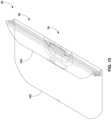
- FIG. 1is a perspective view of an example surgical system that may be draped with a drape according to the disclosure.
- FIGS. 2 and 3are perspective illustrations of an example drape.
- FIGS. 4 and 5are a side view and perspective view, respectively, showing an example layout of a basin portion that can be used for the drape of FIGS. 2 and 3 .
- FIG. 6is a perspective view showing an example arrangement of window portions relative to a basin portion that can be used for the drape of FIGS. 2 and 3 .
- FIG. 7is a sectional view illustrating an example configuration of a basin portion where the thickness of the basin portion varies.
- FIG. 8is a perspective view showing an example collapsed configuration for the drape of FIGS. 2 and 3 .
- FIG. 9is a perspective view of an example portion of a drape showing how an electronically readable tag may be arranged in the drape.
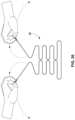
- FIGS. 10 - 26illustrate example folding and packaging steps that may be utilized for a drape according to the disclosure.
- a drape according to the disclosureis individually pre-packaged and is sterilized so as to be free from bacteria or other living organisms.
- the drapemay be subject to thermal treatment and/or chemical treatment (e.g., exposed to ethylene oxide) to provide a sterilized drape that can be arranged over medical equipment within an operating environment to establish a sterile field over the medical equipment so draped.
- the drapecan be disposed after use and a new drape used during a subsequent medical procedure or, in the case of a long procedure, during a latter portion of the same medical procedure.
- a drapeis configured with a basin portion and a side sheet portion.
- the side sheet portioncan be operatively connected to the basin portion and, in some configurations, extend outwardly away from the basin portion.
- the entire drapemay be formed of flexible sheet material(s) that can be deformed under human hand pressure.
- the drapemay be folded into a compact, substantially flat package with the basin portion collapsed in on itself and the side sheet portion folded over the collapsed basin.
- an operatorcan remove the drape from the package and insert the collapsed basin portion over a corresponding piece of medical equipment to be draped.
- the operatorcan expand the collapsed basin portion into its expanded shape, substantially conforming the walls of the basin portion to the corresponding piece of medical equipment to be draped.
- the side sheet portionmay drape downwardly over the piece of medical equipment.
- a more compact packagemay be provided for transport and storage than if a drape structure was fabricated by attaching a flexible plastic drape around a rigid basin.
- a drape according to the disclosurecan be used to drape any type of equipment that is desirably covered during use, the drape may be particularly useful to drape equipment used within a medical environment to provide a sterile draped surface over the equipment.
- Reference to a medical, surgical, or operating environmentincludes any hospital, clinic, facility or location where illness or injuries are diagnosed or treated using interventional or non-interventional techniques.
- Example pieces of medical equipment that may be draped using a drape with a basin portion according to the disclosureinclude, but are not limited to, a sink basin, a weighing trough to weight materials introduced into or removed from a patient, a basin to hold material used during a surgical procedure (e.g., tools, swabs), and the like.
- a drapemay be deployed over a system for thermally treating surgical fluid before utilizing the fluid during a medical procedure.
- the surgical fluidmay be temperature adjusted within the system to raise the temperature above ambient temperature or reduce the temperature below ambient temperature.
- the systemcan also maintain the surgical fluid at an elevated or reduced temperature relative to ambient temperature until the surgical fluid is ready to be used during a procedure.
- FIG. 1is a perspective view of one example of a system 10 for thermally treating surgical fluids that may be draped with a drape according to the disclosure.
- system 10includes a base 12 and a basin 14 .
- Basin 14is supported by and vertically elevated above base 12 .
- Basin 14can provide an open reservoir into which surgical fluid can be dispensed or other material being processed introduced.
- the surgical fluidcan be temperature adjusted within the basin.
- basin 14may be thermally coupled to a thermal treatment device that can raise or lower the temperature of thermal fluid.
- Basin 14can also maintain surgical fluid at a target temperature until the fluid is removed from the basin and used in a procedure.
- system 10can heat surgical fluid in basin 14 to a temperature near a patient's normal body temperature, such as a temperature within the range of 90 degrees F. (32.2 C.) to 120 degrees F. (48.9 C.), such as from 95 degrees F. (35 C.) to 105 degrees F. (40.6 C.).
- system 10may include a user interface.
- system 10includes at least one user interface 16 .
- User interface 16can include a user input through which a clinician inputs information to system 10 and a user output from which the clinician receives information from the system.
- user interface 16may include one or more manipulable inputs that the clinician can interact with to adjust settings of system 10 , provide an indication that fresh fluid is being added to basin 14 , provide an indication that non-surgical components are being added or removed from system 10 , change a temperature to which fluid in basin 14 is heated, or the like.
- the manipulable user inputmay be implemented as physically depressible buttons (e.g., switches), portions of a touch screen that a clinician can interact with, or other features that a clinician can interact with to convey information to system 10 .
- the user output of user interface 16may be a display that provides graphical and/or textual information concerning the operation of system 10 .
- system 10can be configured with a single display or multiple displays.
- system 10is illustrated as having a first display that forms part of user interface 16 and a second display 18 .
- the first displayis positioned on an exterior surface of one side of basin 14 while the second display is positioned on an exterior surface on a substantially opposite side of the basin.
- second display 18is part of a user interface that includes the same features and functionalities (e.g., user input(s) and/or user output(s)) as first user interface 16 .
- second display 18may be a display that provide a user output but does not have user input controls. In these applications, the clinician may enter information or commands through user input(s) on user interface 16 but be able to view output information on both displays.
- any type of materialmay be introduced into and removed from basin 14 during a procedure, including any type of surgical fluid during a medical procedure.
- Example types of medical fluid that may be used during a medical procedureinclude water, saline, or the like.
- the surgical fluidmay or may not include medicament, such as compounds imparting antibacterial properties, anticoagulation/coagulation properties, anesthesia properties, or the like.
- Alternative materials that may be introduced into basin 14can include a medical specimen extracted from a patient for weighing (e.g., in embodiments in which basin is configured to measure weight), blood, platelets, or materials for thermal adjustment before being introduced into a patient, or non-medical related materials (e.g., in applications in which system 10 is not used in a medical environment).
- medical toolsmay be added and removed from basin 14 during use, such as an asepto bulb syringe and/or a graduated measuring container.
- basin 14is supported by and vertically elevated above base 12 .
- basin 14is mounted on an elongated housing 20 that extends vertically upwardly from base 12 .
- Base 12 and housing 20can elevate basin 14 to a position where it is convenient for a clinician to interact with the basin. Additional details on example thermal treatment systems can be found in U.S. patent application Ser. No. 15/469,476, filed Mar. 24, 2017, the entire contents of which are incorporated herein by reference.
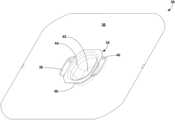
- FIGS. 2 and 3are perspective illustrations of an example drape 30 that may be used to drape system 10 in FIG. 1 or any other desired piece of equipment.
- FIG. 2is an exploded perspective view of drape 30
- FIG. 3illustrates the drape in assembled form.
- drape 30can be formed from a flexible sheet of material 32 that has a basin portion 34 and side sheet portion 36 .
- Side sheet portion 36can at least partially, and in the illustrated example entirely, surround the perimeter of basin portion 34 .
- Side sheet portion 36can be physically connected to basin portion 34 to define a unitary, unbroken sheeting surface. In some configurations such as that illustrated in FIGS.
- drape 30includes one or more window portions 38 , 40 .
- the window portions 38 , 40 of drape 30may be arranged and designed to be positioned over viewable and/or interactable features of the equipment being draped, such as user interface 16 and/or display 18 in system 10 of FIG. 1 .
- Basin portion 34 of drape 30can be collapsible to facilitate flat folding and packing of drape 30 and expandable to facilitate insertion of the basin portion into a basin to be draped during use.
- Basin portion 34 in FIGS. 2 and 3is illustrated in an expanded configuration where the basin portion defines its maximum volume, e.g., such as the configuration when the drape is in use and basin portion 34 of drape 30 is inserted into basin 14 of system 10 .
- Basin portion 34 of drape 30can be collapsible so that the basin portion folds down into a more compact shape and is substantially planar (e.g., FIG. 7 ).
- Basin portion 34 of drape 30may define a reservoir that receives and holds surgical fluid or other materials inserted into the equipment being draped with the drape positioned therebetween.
- Basin portion 34 of drape 30can define any polygonal (e.g., rectangle, square, hexagonal) or arcuate (e.g., circular, elliptical) shape, or even combinations of polygonal and arcuate shapes.
- basin portion 34is shown as a general oval shape and includes a bottom wall 42 and at least one sidewall 44 extending vertically upwardly away from the base (e.g., when basin portion is expanded and not collapsed). Bottom wall 42 and sidewall 44 can collectively form a bounded cavity with an open top surface that receives and holds materials inserted into the covered equipment with the drape positioned between the equipment and the material.
- Side sheet portion 36 of drape 30can be connected to basin portion 34 and extend outwardly and/or downwardly away from the basin portion.
- basin portion 34may define a perimeter 46 that delimits the basin portion.
- the perimeter 46 of basin portion 34may be where the basin portion transitions from a vertical-orientated sidewall defining a reservoir depth or height (e.g., when in the expanded configuration) to a horizontally-oriented sidewall.
- side sheet portion 36can be physically connected to perimeter 46 of basin portion, e.g., either directly or indirectly with a window 38 , 40 positioned between the perimeter and the side sheet.
- Side sheet portion 36can be flexible and fall or drape downwardly under the force of gravity over the equipment which the drape is installed.
- basin portion 34can be inserted into basin 14 of the system with side sheet portion 36 draping downwardly over at least a portion of the exterior surface of basin 14 and/or housing 24 .
- basin portion 34 of drape 30may be shape-indexed to the shape of the basin or reservoir into which basin portion 34 is intended to be inserted.
- Basin portion 34may be shape-indexed in that it may have a complementary size and/or shape to the reservoir or basin of the equipment to be draped and into which basin portion 34 is intended to be inserted.
- basin portion 34may be shape-indexed so that bottom wall 42 and sidewall 44 are in physical contact with and/or conform to corresponding wall surfaces of the structure into which the draped basin portion is inserted (e.g., basin 14 of system 10 in FIG. 1 ). Conforming the shape of basin portion 34 to the structure into which it is intended to be inserted can be useful, e.g., to facilitate efficient thermal transfer between the heated or cooled wall surfaces of the structure and the material contained within basin portion 34 whose temperature is being adjusted.
- the shape of basin portion 34can be established by the configuration of bottom wall 42 and the at least one sidewall 44 .
- sidewall 44extends upwardly from bottom wall 42 .
- the number of sidewalls interconnected together to form the side structure of basin portion 34can vary depending on the shape of the reservoir.
- a basin portion with a circular cross-sectional shapee.g., in the horizontal plane
- a basin portion with a square or rectangular cross-sectional shapemay be defined by four interconnected sidewalls.
- the at least one sidewall 44 defining basin portion 34is sloped such that the sidewall extends vertically upwardly and outwardly away from bottom wall 42 .
- sidewall 44may be curved and define a radius of curvature where the sidewall intersects and joins bottom wall 42 .
- Bottom wall 42may be flat, curved, or have other suitable shape profile. Configuring sidewall 44 with a curved or sloped profile instead of a straight sidewall may help prevent materials from accumulating in corners where sidewall 44 intersects bottom wall 42 .
- basin portion 34may define an arcuate shape devoid of 90 degree angles to help prevent materials from accumulating in such angular regions. That being said, in other examples, sidewall 44 may not be curved but may instead be straight (e.g., perpendicular with respect to ground).
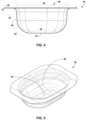
- FIGS. 4 and 5are a side view and perspective view, respectively, of basin portion 34 showing an example layout of the basin portion.
- sidewall 44defines a radius of curvature 45 where the sidewall extends outwardly from and joins to bottom wall 42 .
- basin portion 34may define an open top surface 48 that has a greater cross-sectional area 50 then the cross-sectional area 52 defined by bottom wall 42 .
- Configuring basin portion 34 so the open top surface 48 defined by the basin portion is larger than bottom wall 42may be useful to provide space for the basin portion to collapse into a compact profile.
- basin portion 34may collapse telescopically such that bottom wall 42 is arranged substantially coplanar with perimeter 46 and sidewall 44 is nested or folded in rings of collapsed/gathered material between the bottom wall and upper end of the sidewall.
- sidewall 44extends vertically upwardly from bottom wall 42 and defines a curved perimeter lip 54 .
- the curve perimeter lip 54may be a transition region of sidewall 44 that transitions from a generally vertical orientation to a generally horizontal orientation.
- curved perimeter lip 54 of basin portion 34may transition sidewall 44 from a generally upward vertical orientation, to a generally horizontal orientation, and then to a generally downward vertical orientation.
- sidewall 44may extend upwardly from bottom wall 42 to an inflection point 56 and then extend downwardly from the inflection point toward ground (e.g., when installed over the object being draped).
- the weight of side sheet portion 36 hanging down toward ground under a force of gravitymay help impart this curvature to the perimeter lip of basin portion 34 .
- Configuring basin portion 34 with a curved perimeter lipmay be useful to help the basin portion wrap over the top surface of the basin or reservoir of the equipment being draped with drape 30 .
- drape 30is illustrated as having a single basin portion 34 for being inserted into a corresponding basin of equipment being draped, the drape may be formed with multiple basin portions separated from each other by a wall of material.
- basin portion 34may be a single cavity with internal partition(s) or divider(s) separating one or more reservoir cavities from fluid communication with one or more other reservoir cavities.
- drape 30may include multiple basin portions 34 separated from each other but physically joined together.
- drape 30may include at least one window portion which, in the example of FIGS. 2 and 3 , is illustrated as two window portions 38 , 40 .
- Each window portionmay be a transparent region that is configured to be positioned over user interface features of the equipment being draped.
- drape 30may include a first window portion 38 configured to be positioned over user interface 16 of system 10 ( FIG. 1 ) and a second window portion 40 configured to be positioned over display 18 of system 10 .
- drape 30When drape 30 includes a window portion, the location of the window portion relative to basin portion 34 may vary depending on the configuration of the equipment intended to be draped. In some examples, drape 30 includes at least one window portion positioned between basin portion 34 and side sheet portion 36 . The window portion can be connected to basin portion 34 and side sheet portion 36 , collectively forming an unbroken drape surface.
- FIG. 6is a perspective view of basin portion 34 showing an example arrangement of window portions 38 and 40 relative to the basin portion.
- basin portion 34defines a perimeter 46 having a length 58 and a width 60 .
- first window portion 38projects away from one lengthwise perimeter section of basin portion 34 .
- Second window portion 40projects away from the opposite lengthwise perimeter section of basin portion 34 .
- no window portionprojects away from the widthwise perimeter sections of the basin portion, although other window arrangements can be used without departing from the scope of disclosure.
- basin portion 34is illustrated as defining an oval-shaped cavity formed, collectively, by bottom wall 42 and sidewall 44 .
- the oval-shaped cavitytransitions to a generally rectangular shape about perimeter 46 .
- perimeter lip 54 of sidewall 44is illustrated as transitioning from the oval cross-sectional shape to the generally rectangular cross-sectional shape.
- the corners of the generally rectangular perimeter shape for basin portion 34are illustrated as being chamfered or rounded, although may intersect at sharp (e.g., 90°) angles in other configurations.
- drape 30can be fabricated from any suitable materials, the drape may typically be fabricated from one or more polymeric materials.
- Example polymers that may be used to fabricate drape 30include, but are not limited to, polyethylene, polypropylene, polyvinyl chloride, polystyrene, polyamide, polytetrafluoroethylene (PTFE), polyethylene terephthalate (PET), polyurethane, and combinations thereof.
- the specific material or materials used to form drape 30may be selected based on the desired performance characteristics of the drape, such as its chemical and/or thermal resistance, its puncture resistance, its flexibility, or yet further performance characteristic.
- at least basin portion 34may be selected for temperature compatibility with the equipment being draped.
- drape 30 and/or basin portion 34 of the drapemay be formed of a polymer having a melt temperature rater than 100° F., such as greater than 120° F., greater than 130° F., or greater than 150° F. This may be useful for draping over a thermal warmer, such as the example thermal warmer illustrated in FIG. 1 , in applications where the contents placed in basin portion 34 are heated around the temperature of the human body or slightly above that temperature.
- each portion of drape 30(e.g., basin portion 34 , side sheet portion 36 , and windows 38 , 40 ) are formed of the same polymer.
- at least one portion of drape 30may be formed of a different polymer composition then at least one (and optionally all) of the other portions forming the drape.
- basin portion 34may be formed of a first polymer composition
- windows 38 , 40may be formed of a second polymer composition
- side sheet portion 36may be formed of a third polymer composition.
- the first, second, and third polymer compositionsmay each be different from each other.
- each polymer compositionmay be formed from different types of monomers, or multiple (e.g., all) of the polymer compositions may be formed from the same type of monomer with different constituent ingredients included in the formulation to provide a different resulting composition.
- the first, second, and third polymer compositionsmay each be formed from a polyurethane monomer but may having different formulations to provide compositions different from each other.
- the pre-polymerization resins used to fabricate the first, second, and third polymer compositionsmay contain a common polyurethane monomer but may include different additives and/or constituent ingredients. Additionally or alternatively, the type and/or degree of polymerization may vary between the different polymer compositions used to fabricate the different portions of drape 30 .
- the second polymer composition used to fabricate window portions 38 , 40is selected to have tackier surface properties than the first polymer composition used to fabricate basin portion 34 and the third polymer composition used to fabricate side sheet portion 36 .
- the second polymer compositionmay have a tackifying agent (e.g., in different amounts and/or a different composition than in the first and third polymer compositions) that impacts the tackiness of window portions 38 , 40 .
- Example tackifying agentsthat may be used include, but are not limited to, aliphatic hydrocarbon resins; rosin esters and rosin acids; mixed aliphatic/aromatic tackifying resins; polyterpene tackifiers; and hydrogenated tackifying resins, such as those produced from the polymerization and subsequent hydrogenation of aromatic feedstocks such as styrene, alpha-methyl styrene, and vinyl toluene.
- Fabricating window portions 38 , 40 from a polymeric composition that imparts tackiness and/or resistance to sliding frictionmay be useful to facilitate user interaction with the portion of the draped equipment underlying window portions 38 , 40 .
- the comparatively greater tackiness of window portions 38 , 40 than basin portion 34 and/or side sheet portion 36may be useful to help prevent the window portions from moving if a user presses against one of the window portions to interact with equipment features under the window portion.
- a window portionoverlies a user interface of a draped piece of equipment
- a usermay press against the window portion to engage the user interface covered by the window portion.
- the material(s) used to fabricate the window portions of drape 30exhibits a coefficient of friction according to ASTM D1894 greater than 1 and/or may be too tacky to test according to the standard.
- the different portionsmay have any degree of optical transparency ranging from transparent to opaque, in each case within the visible light spectrum.
- drape 30 or any portion thereofmay be transparent, translucent, or opaque.
- window portions 38 , 40are transparent
- side sheet portion 36is transparent or translucent. This configuration can help a user see features and/or components of the equipment draped under the window portions and/or side sheet portion.
- any portion of drape 30may or may not be colored, e.g., by incorporating a dye or pigment in a polymeric composition forming the drape.
- Drape 30 or a portion thereof, such as side sheet portion 36may be blue to help visually designate that the drape is defining a sterile area.
- drape 30When drape 30 is formed from one or more polymeric materials, polymeric processing techniques may be used to fabricate the drape or any portion thereof.
- drape 30may be formed using casting, extrusion, calendaring, and/or other polymeric processing technique.
- drape 30 or any portion thereofis formed from an extruded polymeric film, which may be a single layer film or multilayer film of the same or different chemical constituents.
- basin portion 34 of drape 30may be formed using a thermoforming technique to produce a thermoformed basin.
- Thermoforminggenerally involves heating a plastic sheet until it is pliable (e.g., optionally above the glass transition temperature) and stretching it over a mold having the inverse shape of the shape desired to be imparted into the sheet being thermoformed.
- the polymeric sheetcan have the shape of the mold imparted into it upon cooling, e.g., resulting in a thermoformed basin portion 34 .
- the thermoforming processmay occur under vacuum pressure or positive pressure.
- a plastic sheetmay be heated until it is pliable (e.g., optionally above the glass transition temperature) and then vacuum drawn down into a mold having the same shape as the shape desired to be imparted into the sheet being thermoformed.
- basin portion 34 of drape 30may be formed using other polymer shaping techniques, such as injection molding, blow molding, or rotational molding, thermoforming may be useful to produce a basin portion that has a thinner thickness than would result if using other polymer shaping techniques.
- Basin portion 34 of drape 30may collapse more readily to facilitate packing and storage when it is formed of a thinner gauge material than if it is formed of a thicker gauge material that does not collapse into a planar shape.
- basin portion 34is fabricated from a thicker material than the side sheet portion 36 . Fabricating basin portion 34 from a thicker material may be helpful to prevent surgical tools or other potentially sharp objects placed in basin portion 34 during use from puncturing the drape. By contrast, fabricating side sheet portion 36 from a comparatively thinner material may increase the flexibility of the side sheet portion, helping the side sheet portion drape downwardly over the object covered by drape 30 .
- basin portion 34has a thickness ranging from 0.05 mm to 1 mm, such as from 0.1 mm to 0.5 mm.
- Side sheet portion 36may have a thickness less than mm, such as less than 0.15 mm, or less than 0.05 mm.
- side sheet portion 36may have a thickness ranging from 0.025 mm to 0.15 mm, such as from 0.05 mm to 0.08 mm.
- a window portion of drape 30(such as window portions 38 , 40 , when included) can have a thickness substantially equal to that of side sheet portion 36 , basin portion 34 , or yet a different thickness.
- the window portion(s) of drape 30may have a thickness that is thinner than that of the side sheet portion 36 and/or basin portion 34 .
- the window portion(s)may have a thickness and be constructed of a material that allows a screen and/or buttons under the window to be tactile and feelable to a user pressing the screen and/or buttons through the window.
- window portion(s) of drape 30may have a thickness ranging from 0.05 mm to 0.1 mm. The thickness of each portion of drape 30 may be constant across the drape or may vary across the drape.
- FIG. 7is a sectional view of basin portion 34 illustrating an example configuration of the basin where the thickness of the basin varies.
- basin portion 34defines a maximum thickness 62 at its perimeter edge 46 .
- the thickness of the material forming basin portion 34tapers to a minimum thickness 64 at bottom wall 42 .
- FIG. 7illustrates the thickness of material progressively and continuously decreasing in thickness along sidewall 44 between perimeter edge 46 and bottom wall 42 , in other configurations, the taper may be discontinuous or may be to a different extent than illustrated in the example figure.
- the material forming basin portion 34may be tapered during the thermoforming process as the polymeric sheet used to form the basin portion is stretched to assume the basin shape. This can result in a thinning of material over the region in which the basin depression is defined as compared to the substantially horizontal/planar perimeter edge of the basin portion, which may be substantially un-deformed through the thermoforming process.
- the thickness of sidewall 44varies from a maximum thickness 62 equal to or greater than 0.4 mm to a minimum thickness 64 where the sidewall joins bottom wall 42 less than 0.4 mm.
- the maximum thickness 62 of sidewall 44may range from 0.4 mm to 0.7 mm.
- the minimum thickness 64 of sidewall 44may range from 0.1 mm to 0.2 mm. Accordingly, a ratio of a maximum thickness divided by a minimum thickness of the basin portion 34 may range from 2 to 10, such as from 3 to 5, although other thickness ratios may be used.
- the thicknessmay be sufficiently small so as to allow the sidewall of the basin portion to collapse.
- Sidewall 44may collapse by deforming the sidewall under human hand pressure, causing the sidewall to lose structural rigidity and fold or crumple upon itself.
- the sidewall 44may be reversibly expanded by applying an expansion force under human hand pressure opposite the deformation force, causing the folded or crumpled sidewall to elongate and/or stretch out to assume its stretched, wall-like structure.
- bottom wall 42 of basin portion 34may be rigid or may be as flexible and collapsible (or even more so) than sidewall 44 .
- drape 30may be fabricated from a single sheet of material (which may itself be a single layer of material or multiple layers of material integrally bonded together, such as through co-extrusion) or may be fabricated from different sections of material joined together.
- each portion of drape 30e.g., side sheet portion 36 , basin portion 34 , windows 38 , 40
- drape 30may be formed separately (e.g., from separate sections of material) and joined together to form drape 30 .
- drape 30may be formed from a single, unitary sheet of material in which basin portion 34 is formed to define the drape. Accordingly, while the different portions of drape 30 are described as being connected together herein, it should be appreciated that the portions may be physically connected by being part of a common sheet of material or may be physically connected by bonding different sheets or sections of material together to form drape 30 .
- each portion of drape 30(e.g., side sheet portion 36 , basin portion 34 , windows 38 , 40 ) are formed from separate sections or sheets of material, e.g., each of which has a different polymeric composition.
- Each portion of drape 30may be cut to a size suitable for incorporation into the resulting drape, e.g., with the edge of the cut portion overlapping an adjacent portion to form a bond therebetween. Any suitable bonding technique can be used to join different portions of drape 30 together to form the resultant drape structure.
- drape 30may be bonded together using an adhesive and/or thermal bonding, such as ultrasonic bonding, RF bonding, laser bonding, or other bonding technique which uses heat to melt and integrally join overlapping sections of polymeric material to form a bond there between.
- an adhesive and/or thermal bondingsuch as ultrasonic bonding, RF bonding, laser bonding, or other bonding technique which uses heat to melt and integrally join overlapping sections of polymeric material to form a bond there between.
- Basin portion 34 of drape 30can define a height 66 ( FIG. 7 ) that varies depending on whether the basin is in its fully expanded form (deployed use state) or whether it is in its fully collapsed form (packaged state).
- the height 66 of basin portion 34ranges from 75 mm to 150 mm when the basin is fully expanded.
- the height of the basin portionmay be less than 50 mm, such as less than 25 mm.
- bottom wall 42 and sidewall 44may be folded up into the void space defined by the basin portion in its otherwise expanded state, as indicated by arrows 68 on FIG. 7 .
- bottom wall 42 of basin portion 34may be pushed upward and/or side sheet portion 32 pushed downward relative to the basin portion until the bottom wall is substantially coplanar with the side sheet portion.
- sidewall 44may collapse inwardly to also be substantially coplanar with the bottom wall and side sheet portion.
- the cavity defined by basin portion 34 in its expanded statecan be eliminated to provide a substantially flat or planar drape. This can facilitate further folding and/or packaging of the drape to provide a compact structure for storage.
- FIG. 8is a perspective view of drape 30 shown with basin portion 34 collapsed to provide a planar flexible sheet.
- drape 30may define a height 70 less than 25 mm when basin portion 34 is collapsed, such as less than 10 mm, lesson 5 mm, or less than 1 mm.
- height 70ranges from 1 mm to 50 mm when basin portion 34 is collapsed, such as from 5 mm to 25 mm. The height 70 can be measured when basin portion 34 is collapsed and side sheet portion 36 is unfolded (e.g., as opposed to being stacked on top of the collapsed basin portion).
- Drape 30may include a variety of features to enhance the performance and/or functionality of the drape.
- drape 30may include an electronically readable tag embedded in the drape.
- the electronically readable tagmay be positioned in a pocket formed by bonding two sheets of material together.
- the electronically readable tagmay be positioned within any portion(s) of drape 30 , e.g., to appropriately align the tag relative to the location of a corresponding non-contact electronic tag reader associated with the equipment being covered by drape 30 .
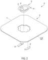
- FIG. 9is a perspective view of an example portion of drape 30 showing how an electronically readable tag 80 may be arranged in the drape portion.
- tag 80is positioned within a first window portion 38 of drape 30 , although the tag may be positioned at other locations and/or in other portions of the drape without departing from the disclosure.
- the electronically readable tag 80may be bonded between multiple layers of multiple.
- electronically readable tag 80is illustrated as being positioned between a first layer of material 82 and a second layer of material 84 .
- Each layer of material 82 , 84may itself be a single layer of material or multiple layers of material integrally bonded together, such as through co-extrusion, to form a composite layer having an inner face and an outer face.
- the first layer of material 82 and the second layer of material 84can be bonded together, e.g., using any of the bonding techniques discussed above, to seal the electronically readable tag 80 in the space between the layers of material.
- the layers of materialmay be sealed and/or joined together directly up to the perimeter of the electronically readable tag 80 or may be joined together to form a pocket surrounding and separated from the perimeter edge of electronically readable tag 80 .
- a small slit 86(e.g., having a length less than the length of electronically readable tag 80 ) is formed through one of the layers of material between which the electronically readable tag 80 is positioned. Slit 86 can help during subsequent sterilization of drape 80 , e.g., allowing a chemical sterilization gas such as ethylene oxide to flow into the space between the layers of material 82 , 84 for sterilization.
- Electronically readable tag 80may be any type of non-transitory electronically readable medium and may be readable using a non-contact reader.
- electronically readable tag 80may be implemented using as a bar code, a radio frequency identification (RFID) tag, or a near field communication (NFC) tag.
- RFIDradio frequency identification
- NFCnear field communication
- the electronically readable tag 80may or may not be covered with a manufacturer or distributor logo or trademark, such as by placing a sticker bearing the trademark over the electronically readable tag 80 .
- drape 30may be sterilized to provide a sterile covering over the equipment draped for medical procedure. Drape 30 may be sterilized after fabrication, and optionally, after being packaged. To help ensure that drape 30 does not inadvertently become contaminated by an operator during the process of removing the drape from its packaging and deploying it over the equipment to be draped, drape 30 may be packaged so as to promote sterile and aseptic removal and deployment of the drape. For example, drape 30 may be folded and packaged in such a way that the user can remove the drape from its packaging and employ it over the equipment to be draped while minimizing or eliminating the extent to which the user touches the sterile, outward facing, surfaces of the drape defining the sterile field.
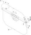
- FIGS. 8 and 10 - 26illustrate example folding and packaging steps that may be utilized to produce a folded drape that facilitates subsequent sterile removal and deployment.
- drape 30is illustrated as being arranged in a substantially planar or flat layout, which may be achieved by laying the drape out on a table surface for folding. Basin portion 34 is collapsed to be substantially planar with side sheet portion 36 .
- drape 30defines a first perimeter edge 100 and a second perimeter edge 102 on an opposite side of the drape from the first perimeter edge.
- the first perimeter edge 100 and the second perimeter edge 102are lengthwise edges of a generally rectangular-shaped drape perimeter.
- the perimeter edges used for foldingmay be width-wise edges of a drape having a rectangular-shaped perimeter, opposite side edges of a circular-shaped drape perimeter, or other edges defining the outward extent of the drape to be folded.
- first edge 100 of drape 30is folded towards second edge 102 of the drape to form a first fold line 104 .
- the first fold line 104may extend parallel to the basin portion 34 .
- first fold line 104is offset from the basin portion 34 in a direction away from second edge 102 .
- first fold line 104may transect (e.g., cut across) basin portion 34 .
- the first fold linemay bisect basin portion 34 or, in the illustrated example, be offset from a bisecting centerline through basin portion 34 such that first edge 100 is not folded all the way to second edge 102 .
- the first edge 100 of drape 30can be folded back away from second edge 102 , for example in a direction opposite to the direction the first edge was initially folded toward the second edge.
- the first edge 100may be folded back away from second edge 102 a lesser distance than the first edge 100 was previously folded toward the second edge 102 .
- thiscan establish a second fold line 106 offset from the first fold line 104 .
- the distance and/or drape material between the first fold line 104 and second fold line 106can define a first drape panel 108 , which may be a folded section of drape material.
- first drape panel 108may be positioned at least partially, and in some examples fully, over the collapsed basin portion 36 .
- first edge 100 of drape 30may again be folded toward the second edge 102 of the drape.
- the first edge 100may be folded toward second edge 102 a lesser distance than the first edge 100 was previously folded toward the second edge 102 to define a third fold line 110 offset from the second fold line 106 .
- the distance and/or drape material between the second fold line 106 and third fold line 110can define a second drape panel 112 , which may be a second section of folded drape material.
- second drape panel 112may or may not be positioned at least partially, and in some examples fully, over the collapsible basin portion 36 .
- first panel 108may have the same width as second panel 112 or may have a different width.
- the process of folding the first edge 100 of drape 30 toward the second edge 102 and back away from the second edge to define additional fold lines, and correspondingly folded panels of material between the fold lines,can be repeated one or more (e.g., multiple) additional times.
- the number of folds and fold panels created during the folding processmay vary, e.g., based on the size of the drape and the size of each panel created during the folding process.
- FIGS. 12 - 16illustrate additional example folding steps that can be performed on drape 30 to define additional fold lines 114 and additional fold panels 116 between adjacent fold lines.
- first edge 100may be positioned for grasping by a user during subsequent deployment of the drape.
- first edge 100is folded toward second edge 102 to define a final fold line 118 and to position the first edge 100 over the collapsible basin portion 36 .
- first edge 100may be folded toward second edge 102 so the edge is positioned on an axis bisecting basin portion 36 .
- FIG. 18is a side view illustration of drape 30 showing an example arrangement of fold lines and drape panel portions that may be formed through the process of folding the drape.
- the resultant folded drape sectionmay have multiple drape panels stacked vertically on top of each other to define a stacked fold arrangement.
- the cumulative number of drape panels in the vertical stackmay range from 2 panels to 20 panels, such as from 5 drape panels to 15 drape panels.
- the drape panelsmay or may not be positioned over the collapsed basin portion 36 . While the size of each panel may vary, in some examples, each panel ranges from 25 mm to 200 mm, such as from 50 mm to 100 mm.
- Drape 30 in the illustrated exampleis shown as being symmetrical, such that side sheet portion 34 extends the same distance from basin portion 36 to first edge 100 as the side sheet portion extends from basin portion 36 to second edge 102 . Accordingly, the folding process illustrated and described with respect to FIGS. 8 and 10 - 18 with respect to one half of the side sheet portion between basin portion 36 and first edge 100 may be replicated on the second half of side sheet portion 34 , either concurrently with, prior to, or after folding the first half of the side sheet portion. In other configurations of drape 30 , side sheet portion 34 may only extend from one side of basin portion 36 , or may extend a different distance from the basin portion to the first edge 100 than the second edge 102 . Accordingly, the number of folds and/or size of drape panels formed during folding may be the same on each side of basin portion 36 or may be different on different sides of the basin portion.
- FIG. 19is a side view illustration of drape 30 showing an example arrangement of fold lines and drape panel portions that may be formed through the process of folding both sides of the drape. As shown, both sides of drape 30 have been folded to define two vertically stacked sections of panel portions arranged side-by-side next to each other.
- the first stack of panel sectionsincludes first fold line 104 , second fold line 106 , third fold line 110 , etc. to form first drape panel 108 , second drape panel 112 , etc.
- the second stack of panel sectionsincludes a fourth fold line 120 , a fifth fold line 122 , a sixth fold line 124 , etc. to form a third drape panel 126 , a fourth drape panel 128 , etc.
- first edge 100 of drape 30 and the second edge 102 of the drapeare folded towards each other to create the outermost fold of the full drape.
- first edge 100 of drape 30 and second edge 102 of the drapemay be brought into adjacent alignment, and in some examples abutting contact.
- the edgesmay be substantially centered over the collapsed basin portion 34 , such as in alignment with an axis bisecting the basin portion.
- a tag, label, or tabis a fixed to the first edge 100 and/or the second edge 102 .
- the respective labelsmay be co-linearly aligned when the two edges are brought into adjacent alignment and may provide grasping surfaces and/or markers that a user is intended to grasp when opening drape 30 .
- the respective labelsmay be positioned so that a user's hands are positioned at the inner-most surface of the drape when grasping at the labels, which can help minimize the risk of the user touching non-sterile equipment when opening the drape.
- drape 30may be folded further beyond the vertically stacked arrangement illustrated in FIG. 19 .
- FIGS. 20 - 22illustrate additional example folds that may be made to drape 30 to provide a compact folded drape structure.
- opposed folded edges of drape 30may be folded toward each other to reduce the overall size profile of the folded drape.
- drape 30may include a third perimeter edge 130 substantially perpendicular to the first edge 100 and the second edge 102 .
- the drapemay also include a fourth perimeter edge 132 on an opposite side of the drape from the third edge 130 .
- Drapemay be folded by folding a corner 134 formed by an intersection of the third edge 130 with the first fold line 104 toward the second edge 102 and/or fourth fold line 120 . It should be appreciated that the designation of a particular fold line number is used for purposes of discussion, and the fold line need not be in any particular numeric sequence or representative of any particular number of folds imparted to the drape. Drape 30 may also be folded by folding a corner 136 formed by an intersection of the fourth edge 132 with the first fold line 104 toward second edge 102 and/or fourth fold line 120 .
- a corner 138 formed by the intersection of the third edge 130 with the fourth fold line 120may be folded toward first edge 100 and/or first fold line 104 , overlapping corner 134 .
- a corner 140 formed by the intersection of the fourth edge 132 with the fourth fold line 120may be folded toward the first edge 100 and/or first fold line 104 , overlapping corner 136 .
- the overlapping regions of corners 138 and 140 extending beyond the folded body of drape 30may be tucked back under the folded body, as shown in FIG. 22 .
- the ends of the resulting folded bodymay be folded, for example perpendicular to the basin portion 36 , to define a resulting folded drape as illustrated in FIGS. 23 and 24 .
- the folded drapemay be inserted into a container 150 , as shown in FIG. Drape 30 and/or container 150 may then be subject to a sterilization treatment to sterilize drape 30 and/or the contents of container 150 .
- Container 150may be sealed (e.g., hermetically) to close drape 30 in the container before or after sterilization.
- container 150is formed of a polymeric material.
- an operatormay open container 150 and remove drape 30 from the container.
- the operatormay unfold the ends of the folded drape, e.g., reversing the folding process described above.
- the operatormay place drape 30 and, more particularly, basin portion 36 of the drape over a corresponding basin of the equipment to be draped before fully unfolding the drape.
- the operatormay place the basin portion of the drape in/or over the basin of the equipment being draped.
- the operatormay grasp first edge 100 and second edge 102 , e.g., by grasping respective tabs or labels placed on each edge.
- the operatormay then pull the edges outwardly and away from each other, unfolding the vertically folded drape sections, e.g., as illustrated in FIG. 26 .
- the operatormay push the collapsed basin portion 36 downwardly into the basin of the equipment being draped, thereby expanding the collapsed basin portion of the drape and causing the basin portion to conform to the walls of the basin of equipment being draped.
- by folding drape 30so that an operator can deploy the drape while minimizing the extent to which the outward facing surface of the drape is contacted during deployment, the likelihood that the sterile surfaces the drape may be contaminated during deployment are reduced.
Landscapes
- Health & Medical Sciences (AREA)
- Life Sciences & Earth Sciences (AREA)
- Surgery (AREA)
- Biomedical Technology (AREA)
- Public Health (AREA)
- Heart & Thoracic Surgery (AREA)
- Veterinary Medicine (AREA)
- Engineering & Computer Science (AREA)
- Animal Behavior & Ethology (AREA)
- General Health & Medical Sciences (AREA)
- Medical Informatics (AREA)
- Molecular Biology (AREA)
- Vascular Medicine (AREA)
- Physics & Mathematics (AREA)
- Thermal Sciences (AREA)
- Packages (AREA)
- Thermotherapy And Cooling Therapy Devices (AREA)
- Medical Preparation Storing Or Oral Administration Devices (AREA)
- Accommodation For Nursing Or Treatment Tables (AREA)
Abstract
Description
Claims (19)
Priority Applications (2)
| Application Number | Priority Date | Filing Date | Title |
|---|---|---|---|
| US18/453,302US12310692B2 (en) | 2017-09-27 | 2023-08-21 | Surgical drape for thermal treatment basin |
| US19/218,037US20250281256A1 (en) | 2017-09-27 | 2025-05-23 | Surgical drape for thermal treatment basin |
Applications Claiming Priority (3)
| Application Number | Priority Date | Filing Date | Title |
|---|---|---|---|
| US201762564229P | 2017-09-27 | 2017-09-27 | |
| US16/144,706US11730555B2 (en) | 2017-09-27 | 2018-09-27 | Surgical drape for thermal treatment basin |
| US18/453,302US12310692B2 (en) | 2017-09-27 | 2023-08-21 | Surgical drape for thermal treatment basin |
Related Parent Applications (1)
| Application Number | Title | Priority Date | Filing Date |
|---|---|---|---|
| US16/144,706ContinuationUS11730555B2 (en) | 2017-09-27 | 2018-09-27 | Surgical drape for thermal treatment basin |
Related Child Applications (1)
| Application Number | Title | Priority Date | Filing Date |
|---|---|---|---|
| US19/218,037ContinuationUS20250281256A1 (en) | 2017-09-27 | 2025-05-23 | Surgical drape for thermal treatment basin |
Publications (2)
| Publication Number | Publication Date |
|---|---|
| US20230390014A1 US20230390014A1 (en) | 2023-12-07 |
| US12310692B2true US12310692B2 (en) | 2025-05-27 |
Family
ID=63896648
Family Applications (3)
| Application Number | Title | Priority Date | Filing Date |
|---|---|---|---|
| US16/144,706Active2041-02-09US11730555B2 (en) | 2017-09-27 | 2018-09-27 | Surgical drape for thermal treatment basin |
| US18/453,302ActiveUS12310692B2 (en) | 2017-09-27 | 2023-08-21 | Surgical drape for thermal treatment basin |
| US19/218,037PendingUS20250281256A1 (en) | 2017-09-27 | 2025-05-23 | Surgical drape for thermal treatment basin |
Family Applications Before (1)
| Application Number | Title | Priority Date | Filing Date |
|---|---|---|---|
| US16/144,706Active2041-02-09US11730555B2 (en) | 2017-09-27 | 2018-09-27 | Surgical drape for thermal treatment basin |
Family Applications After (1)
| Application Number | Title | Priority Date | Filing Date |
|---|---|---|---|
| US19/218,037PendingUS20250281256A1 (en) | 2017-09-27 | 2025-05-23 | Surgical drape for thermal treatment basin |
Country Status (9)
| Country | Link |
|---|---|
| US (3) | US11730555B2 (en) |
| EP (2) | EP3687433B1 (en) |
| JP (2) | JP7436360B2 (en) |
| CN (2) | CN118924437A (en) |
| CA (1) | CA3077862A1 (en) |
| IL (2) | IL312113B2 (en) |
| MX (2) | MX2020007328A (en) |
| SA (1) | SA520411588B1 (en) |
| WO (1) | WO2019067739A1 (en) |
Families Citing this family (5)
| Publication number | Priority date | Publication date | Assignee | Title |
|---|---|---|---|---|
| ES2833957T3 (en) | 2016-03-25 | 2021-06-16 | Microtek Medical Inc | Medical weighing systems |
| IL312113B2 (en)* | 2017-09-27 | 2025-06-01 | Microtek Medical Inc | Thermal therapy pelvic surgical drape |
| USD869683S1 (en) | 2017-09-27 | 2019-12-10 | Microtek Medical, Inc. | Medical drape |
| US12290332B2 (en) | 2018-11-16 | 2025-05-06 | WEG Surgical Solutions, LLC | Air gap detectors in heating system for draped basin |
| US10973601B2 (en) | 2018-11-16 | 2021-04-13 | WEG Surgical Solutions, LLC | Sterile drape without air-trapping wrinkles for use in warming system |
Citations (81)
| Publication number | Priority date | Publication date | Assignee | Title |
|---|---|---|---|---|
| US3770119A (en) | 1971-08-23 | 1973-11-06 | Baxter Laboratories Inc | Medical procedure tray |
| US3777749A (en) | 1969-10-01 | 1973-12-11 | Kendall & Co | Folded surgical drape |
| US4042109A (en) | 1976-01-21 | 1977-08-16 | C. R. Bard, Inc. | Medical procedure package |
| US4889231A (en)* | 1989-06-06 | 1989-12-26 | Baxter International Inc. | Surgical procedure tray |
| US4934152A (en) | 1989-07-10 | 1990-06-19 | Saniserv Inc. | Apparatus and method for producing sterile slush and heated sterile liquid |
| US4944427A (en) | 1987-09-21 | 1990-07-31 | Nippon Petrochemical Co., Ltd. | Disposable tray for medical use and method of making the same |
| EP0401591A2 (en) | 1989-06-03 | 1990-12-12 | Bayer Ag | Support dressing having limited tendency to foam |
| US5163299A (en) | 1992-03-16 | 1992-11-17 | O.R. Solutions, Inc. | Method and apparatus for producing sterile slush |
| JPH0698852A (en) | 1992-09-22 | 1994-04-12 | Olympus Optical Co Ltd | Endoscope system |
| US5331820A (en) | 1993-09-23 | 1994-07-26 | O.R. Solutions, Inc. | Method and apparatus for forming and collecting surgical slush |
| US5333326A (en) | 1993-03-16 | 1994-08-02 | O. R. Solutions, Inc. | Method and apparatus for producing surgical slush and heated sterile liquid |
| US5402644A (en) | 1994-03-16 | 1995-04-04 | O.R. Solutions, Inc. | Method for maintaining sterile slush |
| US5435322A (en)* | 1992-07-10 | 1995-07-25 | Scherer Healthcare Ltd. | Operating room ring stand basin liner/drape |
| US5443082A (en) | 1990-03-30 | 1995-08-22 | British Technology Group Ltd. | Controlling articles of equipment during surgery |
| US5457962A (en) | 1993-09-23 | 1995-10-17 | O.R. Solutions, Inc. | Sterile drape for use in making surgical slush |
| US5502980A (en) | 1993-09-23 | 1996-04-02 | O. R. Solutions, Inc. | Sterile drape for use in making surgical slush |
| US5522095A (en) | 1993-03-16 | 1996-06-04 | O.R. Solutions, Inc. | Method and apparatus for producing sterile surgical media |
| US5524643A (en) | 1995-05-02 | 1996-06-11 | O.R. Solutions, Inc. | Method and apparatus for detection of liquid and leaks in surgical drapes used with surgical equipment |
| US5615423A (en) | 1993-03-16 | 1997-04-01 | O. R. Solutions, Inc. | Surgical drape with placement indicia |
| US5653938A (en) | 1995-04-26 | 1997-08-05 | O. R. Solutions, Inc. | Method and apparatus for ensuring sterility of surgical drapes used with surgical equipment |
| US5809788A (en) | 1996-03-05 | 1998-09-22 | O.R. Solutions, Inc. | Surgical drape for use in forming and collecting surgical slush |
| US5816252A (en) | 1997-04-29 | 1998-10-06 | O.R. Solutions, Inc. | Surgical drape leak detection method and apparatus |
| US5857467A (en) | 1997-06-20 | 1999-01-12 | O.R. Solutions, Inc. | Reinforced surgical drapes for use with thermal treatment systems |
| US5879621A (en)* | 1995-04-26 | 1999-03-09 | O.R. Solutions, Inc. | Method and apparatus for ensuring sterility of surgical drapes used with surgical equipment |
| US5964161A (en) | 1997-10-30 | 1999-10-12 | Conway; Kay Christine | Expandable tray |
| US6003328A (en) | 1996-03-05 | 1999-12-21 | O.R. Solutions, Inc. | Surgical drape having securing device for attachment to thermal treatment systems |
| US6035855A (en) | 1997-02-25 | 2000-03-14 | O.R. Solutions, Inc. | Surgical drape for use with surgical slush machines having an automatic dislodgement mechanism |
| US6087636A (en) | 1997-02-27 | 2000-07-11 | O.R. Solutions, Inc. | Surgical drape and stand for use in heated thermal treatment basins |
| US6091058A (en) | 1995-04-26 | 2000-07-18 | O.R. Solutions, Inc. | Thermal treatment system and method for maintaining integrity and ensuring sterility of surgical drapes used with surgical equipment |
| US6371121B1 (en) | 2000-05-17 | 2002-04-16 | O.R. Solutions, Inc. | Remote controlled thermal treatment system and method for controlling the system remotely to thermally treat sterile surgical liquid |
| US6615836B1 (en) | 2000-11-27 | 2003-09-09 | Kimberly-Clark Worldwide, Inc. | Surgical drape having a pocket-forming feature |
| RU2219950C2 (en) | 2001-06-05 | 2003-12-27 | Общество с ограниченной ответственностью Производственно-коммерческая фирма "Кварц" | Device for preparation of washing solutions and their delivery to surgery field |
| US20040045954A1 (en) | 2002-09-10 | 2004-03-11 | Lehman Timothy M. | Cover system for heating unit |
| US20040208780A1 (en) | 2001-10-22 | 2004-10-21 | Faries Durward I. | Heated medical instrument stand with surgical drape and method of detecting fluid and leaks in the stand tray |
| US6810881B2 (en) | 2001-10-22 | 2004-11-02 | O.R. Solutions, Inc. | Medical solution thermal treatment system and method of controlling system operation in accordance with detection of solution and leaks in surgical drape containers |
| JP2004333048A (en) | 2003-05-09 | 2004-11-25 | Hitachi Hometec Ltd | Cooking device |
| US6860271B2 (en) | 2000-05-17 | 2005-03-01 | O.R. Solutions, Inc. | Thermal treatment system and method for controlling the system to thermally treat sterile surgical liquid |
| US20060016897A1 (en)* | 2004-07-23 | 2006-01-26 | Terumo Kabushiki Kaisha | Medical products and medical product ordering system |
| CA2620906A1 (en) | 2004-08-24 | 2006-03-02 | C Change Surgical Llc | Basin for use in liquid warming device |
| US7168098B2 (en)* | 2003-01-10 | 2007-01-30 | Michael Akira West | Display system for a garment |
| US7176030B2 (en) | 2002-06-17 | 2007-02-13 | O.R. Solutions, Inc. | Method and apparatus for ensuring sterility of disposable medical items used with medical equipment |
| USD546943S1 (en) | 2005-03-24 | 2007-07-17 | C Change Surgical Llc | Hospital basin |
| USD546944S1 (en) | 2005-03-24 | 2007-07-17 | C Change Surgical Llc | Hospital basin with protrusions |
| USD547444S1 (en) | 2005-03-24 | 2007-07-24 | C Change Surgical Llc | Hospital basin with channel |
| US20080017292A1 (en) | 2006-07-24 | 2008-01-24 | Adroit Development, Inc. | Sterile drape and agitator for making surgical slush |
| US20080065264A1 (en) | 2004-09-03 | 2008-03-13 | Tosho Inc. | Medical Resource Storage and Management Apparatus and Medical Supply Management System |
| US7347210B2 (en)* | 2001-10-22 | 2008-03-25 | O.R. Solutions, Inc. | Surgical drape with conductor and method of detecting fluid and leaks in thermal treatment system Basins |
| US7350373B1 (en) | 2003-12-23 | 2008-04-01 | O.R. Solutions, Inc. | Surgical disk drape and method of dislodging surgical slush within thermal treatment system basins |
| US20080152937A1 (en) | 2004-08-24 | 2008-06-26 | C Change Surgical Llc | Adapter for use with a liquid warming device |
| US7398738B2 (en) | 2005-04-14 | 2008-07-15 | Hekman Furniture Company | Workstation with adjustable height work surface |
| US7418966B2 (en) | 2001-10-22 | 2008-09-02 | O. R. Solutions, Inc. | Surgical drape and method of detecting fluid and leaks in thermal treatment system basins |
| US20080264967A1 (en) | 2007-02-09 | 2008-10-30 | Cerner Innovation, Inc. | Medication dispensing apparatus |
| RU2352312C2 (en) | 2003-06-02 | 2009-04-20 | Мелнлюкке Хелт Кэр Аб | Furniture material for surgical operations |
| US20090112057A1 (en) | 2007-10-26 | 2009-04-30 | Patrick Kammer | Anti-fogging and cleaning apparatus for medical scopes |
| US20090113618A1 (en) | 2007-11-06 | 2009-05-07 | Shamirra Slayton | Portable wash basin cart and disposable personal wash basin |
| US7560667B2 (en) | 2004-08-24 | 2009-07-14 | C Change Surgical Llc | Heating element for liquid warming device |
| US20090198347A1 (en) | 2007-08-16 | 2009-08-06 | Hannes Kirzinger | Access-controlled storage system |
| US20090255540A1 (en) | 2008-04-09 | 2009-10-15 | Faries Jr Durward I | Method and Apparatus for Warming Medical Solutions in a Thermal Treatment System Employing a Removable Basin |
| CN201384756Y (en) | 2009-04-21 | 2010-01-20 | 周卫东 | Big liquid bag warmer for operation |
| US7654402B2 (en) | 2003-12-16 | 2010-02-02 | Dart Industries Inc. | Collapsible container |
| US7671302B1 (en) | 2004-03-23 | 2010-03-02 | O. R. Solutions, Inc. | Thermal treatment system instrument rack and method of selectively thermally treating medical instrument portions |
| US7728262B1 (en) | 2004-03-23 | 2010-06-01 | O.R. Solutions, Inc. | Thermal treatment system instrument rack and method of selectively thermally treating medical instrument portions |
| US7854387B2 (en) | 2004-08-24 | 2010-12-21 | C Change Surgical Llc | Open access sleeve for heated fluid units |
| US7959860B2 (en) | 2001-10-22 | 2011-06-14 | Faries Jr Durward I | System and method of detecting fluid and leaks in thermal treatment system basins |
| RU2428138C2 (en) | 2006-03-22 | 2011-09-10 | Мелнлюкке Хелт Кэр Аб | Surgical sheet with absorbing edge |
| CN202885227U (en) | 2012-11-14 | 2013-04-17 | 新疆维吾尔自治区人民医院 | Water thermostat for operating table |
| US20130152946A1 (en) | 2011-12-20 | 2013-06-20 | James Peter Sosnowski | Surgical Drape |
| US20130247921A1 (en)* | 2010-12-06 | 2013-09-26 | Mayo Foundation For Medical Education And Research | Portal for medical instruments |
| RU2493796C2 (en) | 2008-10-22 | 2013-09-27 | Дохени Ай Инститьют | Sterile surgical tray |
| US20130293353A1 (en) | 2012-05-02 | 2013-11-07 | Tyco Healthcare Group Lp | External Reader for Device Management |
| US20140041669A1 (en) | 2012-08-10 | 2014-02-13 | Kimberly-Clark Worldwide, Inc. | Sterile Drape for Two Tiered Hospital Instrument Table |
| US20140208986A1 (en) | 2013-01-25 | 2014-07-31 | Léon DesRoches | Workstation having automated and powered height, depth and rotational adjusters |
| CN204033502U (en) | 2014-08-05 | 2014-12-24 | 北京健康广济贸易有限公司 | Disposable breast operation bag |
| US8925125B2 (en) | 2010-07-06 | 2015-01-06 | Chene Vert | Method for producing a basin integrated in a receiving plane, receiving plane for carrying out the method and monobloc assembly obtained by the method |
| US20150296900A1 (en)* | 2014-04-19 | 2015-10-22 | Albert Yung-Hsiang Huang | Disposable, Sterile, Windowed Surgical Gown |
| JP2016502435A (en) | 2012-11-14 | 2016-01-28 | インテュイティブ サージカル オペレーションズ, インコーポレイテッド | Smart drape for collision prevention |
| US9367061B2 (en) | 2014-02-07 | 2016-06-14 | Enovate Medical, Llc | Medical cart for dispensing medication |
| AU2016200812B2 (en) | 2011-11-04 | 2016-11-03 | Deka Products Limited Partnership | Medical treatment system and methods using a plurality of fluid lines |
| CN106473635A (en) | 2015-09-02 | 2017-03-08 | 襄阳市第三十九中学 | The basin that can fold |
| US20170274157A1 (en) | 2016-03-25 | 2017-09-28 | Ecolab Usa Inc. | Thermal treatment of surgical fluids |
| US11730555B2 (en)* | 2017-09-27 | 2023-08-22 | Microtek Medical, Inc. | Surgical drape for thermal treatment basin |
Family Cites Families (15)
| Publication number | Priority date | Publication date | Assignee | Title |
|---|---|---|---|---|
| US3698791A (en)* | 1971-04-19 | 1972-10-17 | Xerox Corp | Drape for operating microscope |
| US3791381A (en)* | 1971-09-29 | 1974-02-12 | Johnson & Johnson | Universal surgical drape |
| US4553539A (en)* | 1983-09-30 | 1985-11-19 | Surgikos, Inc. | Bilateral fenestrated drape |
| US6070586A (en)* | 1996-06-05 | 2000-06-06 | Lingeman Medical Products, Inc. | Fluid control drape with conforming lip |
| CN1195900C (en)* | 1998-11-17 | 2005-04-06 | 艾尔坎国际有限公司 | Wettable and erosion/oxidation-resistant carbon-composite materials |
| US7160246B2 (en)* | 2002-10-17 | 2007-01-09 | Microtek Medical, Inc. | System and method for removing a protective cover from a medical instrument |
| DE10311198B4 (en)* | 2003-02-06 | 2016-09-22 | Carl Zeiss Meditec Ag | Holding device with transparent cover for drape and Drape for a surgical microscope with such a holding device |
| US7232230B2 (en)* | 2003-03-24 | 2007-06-19 | Bala Andrew J | Surgical microscope drape with removable lens assembly |
| IL165341A (en)* | 2003-12-16 | 2010-05-31 | Dart Ind Inc | Collapsible container |
| US20080236598A1 (en)* | 2007-03-30 | 2008-10-02 | Fred Gobel | Drape for open tracheal suctioning |
| DE202011101217U1 (en)* | 2011-05-20 | 2012-08-21 | Pemax Kunststoff Gmbh | Plastic lining for tempered bowls |
| JP5931497B2 (en)* | 2011-08-04 | 2016-06-08 | オリンパス株式会社 | Surgery support apparatus and assembly method thereof |
| US8910637B2 (en)* | 2012-12-12 | 2014-12-16 | Marilyn Winer | Sterile drape for robotic surgical equipment |
| JP6043619B2 (en)* | 2012-12-18 | 2016-12-14 | 株式会社リブドゥコーポレーション | Drape and disposable medical equipment set |
| CN111616804B (en)* | 2014-03-17 | 2024-04-09 | 直观外科手术操作公司 | Surgical drape and system including a surgical drape and an attached sensor |
- 2018
- 2018-09-26ILIL312113Apatent/IL312113B2/enunknown
- 2018-09-27CACA3077862Apatent/CA3077862A1/enactivePending
- 2018-09-27ILIL273622Apatent/IL273622B2/enunknown
- 2018-09-27CNCN202411100535.6Apatent/CN118924437A/enactivePending
- 2018-09-27USUS16/144,706patent/US11730555B2/enactiveActive
- 2018-09-27CNCN201880059260.2Apatent/CN111107800B/enactiveActive
- 2018-09-27MXMX2020007328Apatent/MX2020007328A/enunknown
- 2018-09-27EPEP18789296.3Apatent/EP3687433B1/enactiveActive
- 2018-09-27JPJP2020517089Apatent/JP7436360B2/enactiveActive
- 2018-09-27EPEP24187725.7Apatent/EP4454595A1/enactivePending
- 2018-09-27WOPCT/US2018/053154patent/WO2019067739A1/ennot_activeCeased
- 2020
- 2020-03-23SASA520411588Apatent/SA520411588B1/enunknown
- 2020-07-13MXMX2024005008Apatent/MX2024005008A/enunknown
- 2023
- 2023-08-21USUS18/453,302patent/US12310692B2/enactiveActive
- 2024
- 2024-02-08JPJP2024017883Apatent/JP2024042109A/enactivePending
- 2025
- 2025-05-23USUS19/218,037patent/US20250281256A1/enactivePending
Patent Citations (98)
| Publication number | Priority date | Publication date | Assignee | Title |
|---|---|---|---|---|
| US3777749A (en) | 1969-10-01 | 1973-12-11 | Kendall & Co | Folded surgical drape |
| US3770119A (en) | 1971-08-23 | 1973-11-06 | Baxter Laboratories Inc | Medical procedure tray |
| US4042109A (en) | 1976-01-21 | 1977-08-16 | C. R. Bard, Inc. | Medical procedure package |
| US4944427A (en) | 1987-09-21 | 1990-07-31 | Nippon Petrochemical Co., Ltd. | Disposable tray for medical use and method of making the same |
| EP0401591A2 (en) | 1989-06-03 | 1990-12-12 | Bayer Ag | Support dressing having limited tendency to foam |
| US4889231A (en)* | 1989-06-06 | 1989-12-26 | Baxter International Inc. | Surgical procedure tray |
| US4934152A (en) | 1989-07-10 | 1990-06-19 | Saniserv Inc. | Apparatus and method for producing sterile slush and heated sterile liquid |
| US5443082A (en) | 1990-03-30 | 1995-08-22 | British Technology Group Ltd. | Controlling articles of equipment during surgery |
| US5163299A (en) | 1992-03-16 | 1992-11-17 | O.R. Solutions, Inc. | Method and apparatus for producing sterile slush |
| US5435322A (en)* | 1992-07-10 | 1995-07-25 | Scherer Healthcare Ltd. | Operating room ring stand basin liner/drape |
| JPH0698852A (en) | 1992-09-22 | 1994-04-12 | Olympus Optical Co Ltd | Endoscope system |
| US5615423A (en) | 1993-03-16 | 1997-04-01 | O. R. Solutions, Inc. | Surgical drape with placement indicia |
| US5333326A (en) | 1993-03-16 | 1994-08-02 | O. R. Solutions, Inc. | Method and apparatus for producing surgical slush and heated sterile liquid |
| US5522095A (en) | 1993-03-16 | 1996-06-04 | O.R. Solutions, Inc. | Method and apparatus for producing sterile surgical media |
| US5429801A (en) | 1993-03-16 | 1995-07-04 | O.R. Solutions, Inc. | Method and apparatus for producing surgical slush and heated sterile liquid |
| US5400616A (en) | 1993-09-23 | 1995-03-28 | O.R. Solutions, Inc. | Method and apparatus for forming and collecting surgical slush |
| US5457962A (en) | 1993-09-23 | 1995-10-17 | O.R. Solutions, Inc. | Sterile drape for use in making surgical slush |
| US5502980A (en) | 1993-09-23 | 1996-04-02 | O. R. Solutions, Inc. | Sterile drape for use in making surgical slush |
| US5331820A (en) | 1993-09-23 | 1994-07-26 | O.R. Solutions, Inc. | Method and apparatus for forming and collecting surgical slush |
| US5402644A (en) | 1994-03-16 | 1995-04-04 | O.R. Solutions, Inc. | Method for maintaining sterile slush |
| US5551240A (en) | 1994-03-16 | 1996-09-03 | O. R. Solutions, Inc. | Method and apparatus for maintaining temperature control of sterile fluid |
| US5653938A (en) | 1995-04-26 | 1997-08-05 | O. R. Solutions, Inc. | Method and apparatus for ensuring sterility of surgical drapes used with surgical equipment |
| US5879621A (en)* | 1995-04-26 | 1999-03-09 | O.R. Solutions, Inc. | Method and apparatus for ensuring sterility of surgical drapes used with surgical equipment |
| US6091058A (en) | 1995-04-26 | 2000-07-18 | O.R. Solutions, Inc. | Thermal treatment system and method for maintaining integrity and ensuring sterility of surgical drapes used with surgical equipment |
| US6255627B1 (en) | 1995-04-26 | 2001-07-03 | O.R. Solutions, Inc. | Thermal treatment system and method for maintaining integrity and ensuring sterility of surgical drapes used with surgical equipment |
| US5524643A (en) | 1995-05-02 | 1996-06-11 | O.R. Solutions, Inc. | Method and apparatus for detection of liquid and leaks in surgical drapes used with surgical equipment |
| US5809788A (en) | 1996-03-05 | 1998-09-22 | O.R. Solutions, Inc. | Surgical drape for use in forming and collecting surgical slush |
| US5950438A (en) | 1996-03-05 | 1999-09-14 | O.R. Solutions, Inc. | Method and apparatus for manipulating a surgical drape via an inflatable device to collect surgical slush |
| US6003328A (en) | 1996-03-05 | 1999-12-21 | O.R. Solutions, Inc. | Surgical drape having securing device for attachment to thermal treatment systems |
| US6035855A (en) | 1997-02-25 | 2000-03-14 | O.R. Solutions, Inc. | Surgical drape for use with surgical slush machines having an automatic dislodgement mechanism |
| US6087636A (en) | 1997-02-27 | 2000-07-11 | O.R. Solutions, Inc. | Surgical drape and stand for use in heated thermal treatment basins |
| US5816252A (en) | 1997-04-29 | 1998-10-06 | O.R. Solutions, Inc. | Surgical drape leak detection method and apparatus |
| US5857467A (en) | 1997-06-20 | 1999-01-12 | O.R. Solutions, Inc. | Reinforced surgical drapes for use with thermal treatment systems |
| US5964161A (en) | 1997-10-30 | 1999-10-12 | Conway; Kay Christine | Expandable tray |
| US6371121B1 (en) | 2000-05-17 | 2002-04-16 | O.R. Solutions, Inc. | Remote controlled thermal treatment system and method for controlling the system remotely to thermally treat sterile surgical liquid |
| US6860271B2 (en) | 2000-05-17 | 2005-03-01 | O.R. Solutions, Inc. | Thermal treatment system and method for controlling the system to thermally treat sterile surgical liquid |
| US6918395B2 (en) | 2000-05-17 | 2005-07-19 | O.R. Solutions, Inc. | Thermal treatment system and method for controlling the system remotely to thermally treat sterile surgical liquid |
| US6615836B1 (en) | 2000-11-27 | 2003-09-09 | Kimberly-Clark Worldwide, Inc. | Surgical drape having a pocket-forming feature |
| RU2219950C2 (en) | 2001-06-05 | 2003-12-27 | Общество с ограниченной ответственностью Производственно-коммерческая фирма "Кварц" | Device for preparation of washing solutions and their delivery to surgery field |
| US20040208780A1 (en) | 2001-10-22 | 2004-10-21 | Faries Durward I. | Heated medical instrument stand with surgical drape and method of detecting fluid and leaks in the stand tray |
| US6810881B2 (en) | 2001-10-22 | 2004-11-02 | O.R. Solutions, Inc. | Medical solution thermal treatment system and method of controlling system operation in accordance with detection of solution and leaks in surgical drape containers |
| US7959860B2 (en) | 2001-10-22 | 2011-06-14 | Faries Jr Durward I | System and method of detecting fluid and leaks in thermal treatment system basins |
| US6910485B2 (en) | 2001-10-22 | 2005-06-28 | O.R. Solutions, Inc. | Medical solution thermal treatment system and method of controlling system operation in accordance with detection of solution and leaks in surgical drape containers |
| US7418966B2 (en) | 2001-10-22 | 2008-09-02 | O. R. Solutions, Inc. | Surgical drape and method of detecting fluid and leaks in thermal treatment system basins |
| US7347210B2 (en)* | 2001-10-22 | 2008-03-25 | O.R. Solutions, Inc. | Surgical drape with conductor and method of detecting fluid and leaks in thermal treatment system Basins |
| US7176030B2 (en) | 2002-06-17 | 2007-02-13 | O.R. Solutions, Inc. | Method and apparatus for ensuring sterility of disposable medical items used with medical equipment |
| US20040045954A1 (en) | 2002-09-10 | 2004-03-11 | Lehman Timothy M. | Cover system for heating unit |
| US7168098B2 (en)* | 2003-01-10 | 2007-01-30 | Michael Akira West | Display system for a garment |
| JP2004333048A (en) | 2003-05-09 | 2004-11-25 | Hitachi Hometec Ltd | Cooking device |
| RU2352312C2 (en) | 2003-06-02 | 2009-04-20 | Мелнлюкке Хелт Кэр Аб | Furniture material for surgical operations |
| US7654402B2 (en) | 2003-12-16 | 2010-02-02 | Dart Industries Inc. | Collapsible container |
| US7350373B1 (en) | 2003-12-23 | 2008-04-01 | O.R. Solutions, Inc. | Surgical disk drape and method of dislodging surgical slush within thermal treatment system basins |
| US8148667B2 (en) | 2004-03-23 | 2012-04-03 | Ecolab Inc. | Thermal treatment system instrument rack and method of selectively thermally treating medical instrument portions |
| US7728262B1 (en) | 2004-03-23 | 2010-06-01 | O.R. Solutions, Inc. | Thermal treatment system instrument rack and method of selectively thermally treating medical instrument portions |
| US7671302B1 (en) | 2004-03-23 | 2010-03-02 | O. R. Solutions, Inc. | Thermal treatment system instrument rack and method of selectively thermally treating medical instrument portions |
| US20060016897A1 (en)* | 2004-07-23 | 2006-01-26 | Terumo Kabushiki Kaisha | Medical products and medical product ordering system |
| US20080152937A1 (en) | 2004-08-24 | 2008-06-26 | C Change Surgical Llc | Adapter for use with a liquid warming device |
| US7560667B2 (en) | 2004-08-24 | 2009-07-14 | C Change Surgical Llc | Heating element for liquid warming device |
| US7903957B2 (en) | 2004-08-24 | 2011-03-08 | C Change Surgical Llc | Methods using a draped liquid warming device |
| US7128275B2 (en) | 2004-08-24 | 2006-10-31 | C Change Surgical Llc | Liquid warming device with basin |
| US7854387B2 (en) | 2004-08-24 | 2010-12-21 | C Change Surgical Llc | Open access sleeve for heated fluid units |
| CA2620906A1 (en) | 2004-08-24 | 2006-03-02 | C Change Surgical Llc | Basin for use in liquid warming device |
| US7441714B2 (en) | 2004-08-24 | 2008-10-28 | C Change Surgical Llc | Liquid warming system |
| US8138454B2 (en) | 2004-08-24 | 2012-03-20 | C Change Surgical Llc | Liquid warming device with basin detection |
| US7459657B2 (en) | 2004-08-24 | 2008-12-02 | C Change Surgical Llc | Basin for use in liquid warming device |
| CA2620907A1 (en) | 2004-08-24 | 2006-03-02 | C Change Surgical Llc | Liquid warming device with basin |
| US20080065264A1 (en) | 2004-09-03 | 2008-03-13 | Tosho Inc. | Medical Resource Storage and Management Apparatus and Medical Supply Management System |
| USD568989S1 (en) | 2005-03-24 | 2008-05-13 | C Change Surgical Llc | Hospital basin |
| USD547444S1 (en) | 2005-03-24 | 2007-07-24 | C Change Surgical Llc | Hospital basin with channel |
| USD546944S1 (en) | 2005-03-24 | 2007-07-17 | C Change Surgical Llc | Hospital basin with protrusions |
| USD569970S1 (en) | 2005-03-24 | 2008-05-27 | C Change Surgical Llc | Hospital basin with channel |
| USD546943S1 (en) | 2005-03-24 | 2007-07-17 | C Change Surgical Llc | Hospital basin |
| US7398738B2 (en) | 2005-04-14 | 2008-07-15 | Hekman Furniture Company | Workstation with adjustable height work surface |
| RU2428138C2 (en) | 2006-03-22 | 2011-09-10 | Мелнлюкке Хелт Кэр Аб | Surgical sheet with absorbing edge |
| US20080017292A1 (en) | 2006-07-24 | 2008-01-24 | Adroit Development, Inc. | Sterile drape and agitator for making surgical slush |
| US20080264967A1 (en) | 2007-02-09 | 2008-10-30 | Cerner Innovation, Inc. | Medication dispensing apparatus |
| US20090198347A1 (en) | 2007-08-16 | 2009-08-06 | Hannes Kirzinger | Access-controlled storage system |
| US20090112057A1 (en) | 2007-10-26 | 2009-04-30 | Patrick Kammer | Anti-fogging and cleaning apparatus for medical scopes |
| US20090113618A1 (en) | 2007-11-06 | 2009-05-07 | Shamirra Slayton | Portable wash basin cart and disposable personal wash basin |
| US20090255540A1 (en) | 2008-04-09 | 2009-10-15 | Faries Jr Durward I | Method and Apparatus for Warming Medical Solutions in a Thermal Treatment System Employing a Removable Basin |
| RU2493796C2 (en) | 2008-10-22 | 2013-09-27 | Дохени Ай Инститьют | Sterile surgical tray |
| CN201384756Y (en) | 2009-04-21 | 2010-01-20 | 周卫东 | Big liquid bag warmer for operation |
| US8925125B2 (en) | 2010-07-06 | 2015-01-06 | Chene Vert | Method for producing a basin integrated in a receiving plane, receiving plane for carrying out the method and monobloc assembly obtained by the method |
| US20130247921A1 (en)* | 2010-12-06 | 2013-09-26 | Mayo Foundation For Medical Education And Research | Portal for medical instruments |
| AU2016200812B2 (en) | 2011-11-04 | 2016-11-03 | Deka Products Limited Partnership | Medical treatment system and methods using a plurality of fluid lines |
| US20130152946A1 (en) | 2011-12-20 | 2013-06-20 | James Peter Sosnowski | Surgical Drape |
| US20130293353A1 (en) | 2012-05-02 | 2013-11-07 | Tyco Healthcare Group Lp | External Reader for Device Management |
| US20140041669A1 (en) | 2012-08-10 | 2014-02-13 | Kimberly-Clark Worldwide, Inc. | Sterile Drape for Two Tiered Hospital Instrument Table |
| JP2016502435A (en) | 2012-11-14 | 2016-01-28 | インテュイティブ サージカル オペレーションズ, インコーポレイテッド | Smart drape for collision prevention |
| CN202885227U (en) | 2012-11-14 | 2013-04-17 | 新疆维吾尔自治区人民医院 | Water thermostat for operating table |
| US20140208986A1 (en) | 2013-01-25 | 2014-07-31 | Léon DesRoches | Workstation having automated and powered height, depth and rotational adjusters |
| US9367061B2 (en) | 2014-02-07 | 2016-06-14 | Enovate Medical, Llc | Medical cart for dispensing medication |
| US20150296900A1 (en)* | 2014-04-19 | 2015-10-22 | Albert Yung-Hsiang Huang | Disposable, Sterile, Windowed Surgical Gown |
| CN204033502U (en) | 2014-08-05 | 2014-12-24 | 北京健康广济贸易有限公司 | Disposable breast operation bag |
| CN106473635A (en) | 2015-09-02 | 2017-03-08 | 襄阳市第三十九中学 | The basin that can fold |
| US20170274157A1 (en) | 2016-03-25 | 2017-09-28 | Ecolab Usa Inc. | Thermal treatment of surgical fluids |
| US20170274136A1 (en) | 2016-03-25 | 2017-09-28 | Ecolab Usa Inc. | Medical weighing systems |
| US11730555B2 (en)* | 2017-09-27 | 2023-08-22 | Microtek Medical, Inc. | Surgical drape for thermal treatment basin |
Non-Patent Citations (2)
| Title |
|---|
| International Patent Application No. PCT/US2018/053154, International Search Report and Written Opinion mailed Feb. 27, 2019, 21 pages. |
| International Patent Application No. PCT/US2018/053154, Invitation to Pay Additional Fees and Partial Search Report mailed Jan. 2, 2019, 16 pages. |
Also Published As
| Publication number | Publication date |
|---|---|
| CN111107800B (en) | 2024-08-16 |
| IL273622B1 (en) | 2024-05-01 |
| CN118924437A (en) | 2024-11-12 |
| MX2020007328A (en) | 2020-09-07 |
| US20250281256A1 (en) | 2025-09-11 |
| EP4454595A1 (en) | 2024-10-30 |
| US20230390014A1 (en) | 2023-12-07 |
| CA3077862A1 (en) | 2018-09-27 |
| BR112020005983A2 (en) | 2020-09-29 |
| IL312113B2 (en) | 2025-06-01 |
| IL273622A (en) | 2020-05-31 |
| EP3687433B1 (en) | 2024-07-17 |
| IL273622B2 (en) | 2024-09-01 |
| RU2020113524A (en) | 2021-10-27 |
| MX2024005008A (en) | 2024-05-10 |
| JP2024042109A (en) | 2024-03-27 |
| JP2020534909A (en) | 2020-12-03 |
| IL312113A (en) | 2024-06-01 |
| SA520411588B1 (en) | 2024-01-21 |
| JP7436360B2 (en) | 2024-02-21 |
| US11730555B2 (en) | 2023-08-22 |
| EP3687433A1 (en) | 2020-08-05 |
| RU2020113524A3 (en) | 2022-01-13 |
| WO2019067739A1 (en) | 2019-04-04 |
| CN111107800A (en) | 2020-05-05 |
| IL312113B1 (en) | 2025-02-01 |
| US20190090972A1 (en) | 2019-03-28 |
Similar Documents
| Publication | Publication Date | Title |
|---|---|---|
| US12310692B2 (en) | Surgical drape for thermal treatment basin | |
| US11684347B2 (en) | Catheter tray, packaging system, instruction insert, and associated methods | |
| US11707597B2 (en) | Catheter tray, packaging system, and associated methods | |
| US5325987A (en) | Sterile package for surgical devices | |
| EP3100760B1 (en) | Catheterization procedure system | |
| CN101910018A (en) | Rigid containment vessel with rupturable perimeter bubble | |
| US20160015388A1 (en) | Hangable Disposable Bag for Sutures and Other Medical Waste | |
| US20240225768A9 (en) | Packaging System With Folded Sidewalls | |
| RU2786991C2 (en) | Surgical sheet for tray of heat treatment system | |
| BR112020005983B1 (en) | FIELD FOR A SURGICAL FLUID HEAT TREATMENT SYSTEM | |
| US20230263511A1 (en) | Catheter Tray, Packaging System, Instruction Insert, and Associated Methods | |
| CN110151459A (en) | ICU nursing phlegm sucking nursing plate | |
| US20240217706A1 (en) | Package for Medical Devices Including a Pinch-Open Closure | |
| WO2023150606A1 (en) | Package for a sterile medical device and assembly method |
Legal Events
| Date | Code | Title | Description |
|---|---|---|---|
| FEPP | Fee payment procedure | Free format text:ENTITY STATUS SET TO UNDISCOUNTED (ORIGINAL EVENT CODE: BIG.); ENTITY STATUS OF PATENT OWNER: LARGE ENTITY | |
| STPP | Information on status: patent application and granting procedure in general | Free format text:DOCKETED NEW CASE - READY FOR EXAMINATION | |
| AS | Assignment | Owner name:MICROTEK MEDICAL, INC., MISSISSIPPI Free format text:ASSIGNMENT OF ASSIGNORS INTEREST;ASSIGNORS:HENDRIX, HEIDI FRANCES;RAWLINGS, DAVID RICHARD;WILSON, MICHELLE;SIGNING DATES FROM 20180910 TO 20180917;REEL/FRAME:065384/0009 | |
| AS | Assignment | Owner name:MEDLINE INDUSTRIES, LP, ILLINOIS Free format text:ASSIGNMENT OF ASSIGNORS INTEREST;ASSIGNOR:MICROTEK MEDICAL, INC.;REEL/FRAME:068909/0001 Effective date:20240801 | |
| STPP | Information on status: patent application and granting procedure in general | Free format text:NON FINAL ACTION MAILED | |
| STPP | Information on status: patent application and granting procedure in general | Free format text:RESPONSE TO NON-FINAL OFFICE ACTION ENTERED AND FORWARDED TO EXAMINER | |
| STPP | Information on status: patent application and granting procedure in general | Free format text:NOTICE OF ALLOWANCE MAILED -- APPLICATION RECEIVED IN OFFICE OF PUBLICATIONS | |
| STCF | Information on status: patent grant | Free format text:PATENTED CASE | |
| AS | Assignment | Owner name:WILMINGTON TRUST, NATIONAL ASSOCIATION, MINNESOTA Free format text:PATENT SECURITY AGREEMENT;ASSIGNOR:MEDLINE INDUSTRIES, LP;REEL/FRAME:071677/0152 Effective date:20250603 Owner name:BANK OF AMERICA, N.A., AS COLLATERAL AGENT, TEXAS Free format text:PATENT SECURITY AGREEMENT;ASSIGNOR:MEDLINE INDUSTRIES, LP F/K/A MEDLINE INDUSTRIES, INC.;REEL/FRAME:071672/0172 Effective date:20250603 Owner name:WILMINGTON TRUST, NATIONAL ASSOCIATION, MINNESOTA Free format text:PATENT SECURITY AGREEMENT;ASSIGNOR:MEDLINE INDUSTRIES, LP;REEL/FRAME:071808/0640 Effective date:20250603 | |
| AS | Assignment | Owner name:WILMINGTON TRUST, NATIONAL ASSOCIATION, MINNESOTA Free format text:CORRECTIVE ASSIGNMENT TO CORRECT THE PATENT SECURITY AGREEMENT DOCUMENT PREVIOUSLY RECORDED ON REEL 71677 FRAME 152. ASSIGNOR(S) HEREBY CONFIRMS THE PATENT SECURITY AGREEMENT;ASSIGNOR:MEDLINE INDUSTRIES, LP;REEL/FRAME:072235/0868 Effective date:20250603 |