US12310502B2 - Automated task chair - Google Patents
Automated task chairDownload PDFInfo
- Publication number
- US12310502B2 US12310502B2US18/093,923US202318093923AUS12310502B2US 12310502 B2US12310502 B2US 12310502B2US 202318093923 AUS202318093923 AUS 202318093923AUS 12310502 B2US12310502 B2US 12310502B2
- Authority
- US
- United States
- Prior art keywords
- seating device
- seating
- foot support
- seat
- support
- Prior art date
- Legal status (The legal status is an assumption and is not a legal conclusion. Google has not performed a legal analysis and makes no representation as to the accuracy of the status listed.)
- Active
Links
Images


Classifications
- A—HUMAN NECESSITIES
- A47—FURNITURE; DOMESTIC ARTICLES OR APPLIANCES; COFFEE MILLS; SPICE MILLS; SUCTION CLEANERS IN GENERAL
- A47C—CHAIRS; SOFAS; BEDS
- A47C7/00—Parts, details, or accessories of chairs or stools
- A47C7/50—Supports for the feet or the legs
- A47C7/52—Supports for the feet or the legs of detachable type
- A—HUMAN NECESSITIES
- A47—FURNITURE; DOMESTIC ARTICLES OR APPLIANCES; COFFEE MILLS; SPICE MILLS; SUCTION CLEANERS IN GENERAL
- A47C—CHAIRS; SOFAS; BEDS
- A47C1/00—Chairs adapted for special purposes
- A47C1/02—Reclining or easy chairs
- A47C1/031—Reclining or easy chairs having coupled concurrently adjustable supporting parts
- A47C1/032—Reclining or easy chairs having coupled concurrently adjustable supporting parts the parts being movably-coupled seat and back-rest
- A47C1/03255—Reclining or easy chairs having coupled concurrently adjustable supporting parts the parts being movably-coupled seat and back-rest with a central column, e.g. rocking office chairs
- A—HUMAN NECESSITIES
- A47—FURNITURE; DOMESTIC ARTICLES OR APPLIANCES; COFFEE MILLS; SPICE MILLS; SUCTION CLEANERS IN GENERAL
- A47C—CHAIRS; SOFAS; BEDS
- A47C7/00—Parts, details, or accessories of chairs or stools
- A47C7/002—Chair or stool bases
- A47C7/006—Chair or stool bases with castors
- A—HUMAN NECESSITIES
- A47—FURNITURE; DOMESTIC ARTICLES OR APPLIANCES; COFFEE MILLS; SPICE MILLS; SUCTION CLEANERS IN GENERAL
- A47C—CHAIRS; SOFAS; BEDS
- A47C7/00—Parts, details, or accessories of chairs or stools
- A47C7/36—Supports for the head or the back
- A—HUMAN NECESSITIES
- A47—FURNITURE; DOMESTIC ARTICLES OR APPLIANCES; COFFEE MILLS; SPICE MILLS; SUCTION CLEANERS IN GENERAL
- A47C—CHAIRS; SOFAS; BEDS
- A47C7/00—Parts, details, or accessories of chairs or stools
- A47C7/50—Supports for the feet or the legs
- A—HUMAN NECESSITIES
- A47—FURNITURE; DOMESTIC ARTICLES OR APPLIANCES; COFFEE MILLS; SPICE MILLS; SUCTION CLEANERS IN GENERAL
- A47C—CHAIRS; SOFAS; BEDS
- A47C7/00—Parts, details, or accessories of chairs or stools
- A47C7/50—Supports for the feet or the legs
- A47C7/506—Supports for the feet or the legs of adjustable type
- A47C7/5066—Supports for the feet or the legs of adjustable type by rotation
- A—HUMAN NECESSITIES
- A47—FURNITURE; DOMESTIC ARTICLES OR APPLIANCES; COFFEE MILLS; SPICE MILLS; SUCTION CLEANERS IN GENERAL
- A47C—CHAIRS; SOFAS; BEDS
- A47C1/00—Chairs adapted for special purposes
- A47C1/02—Reclining or easy chairs
- A47C1/031—Reclining or easy chairs having coupled concurrently adjustable supporting parts
- A47C1/036—Reclining or easy chairs having coupled concurrently adjustable supporting parts the parts including a head-rest
- A—HUMAN NECESSITIES
- A47—FURNITURE; DOMESTIC ARTICLES OR APPLIANCES; COFFEE MILLS; SPICE MILLS; SUCTION CLEANERS IN GENERAL
- A47C—CHAIRS; SOFAS; BEDS
- A47C7/00—Parts, details, or accessories of chairs or stools
- A47C7/36—Supports for the head or the back
- A47C7/38—Supports for the head or the back for the head, e.g. detachable
Definitions
- the present inventionis in the technical field of ergonomic seating.
- Ergonomicshas become an extremely popular subject in relation to all types of products, and to furniture and seating in particular.
- the wordmeans “the study of people's efficiency in their working environment.”
- the fundamental challenge with chairsis that they force the body into positions in which users remain in relatively fixed positions and do not move for extended periods of time.
- numerous adjustable chairshave been developed for a wide range of applications—from working to resting to rehabilitation.
- More traditional, recent ergonomic chairslike Aeron and Leap, are based on adjustable seating surfaces that are controlled with knobs, levers, air cylinders and torsion springs. These surfaces can be adjusted to conform to a wide range of body sizes, shapes and weights. While traditional seating supports the body in relatively upright positions, more advanced ergonomic chairs can also support the body in a series of positions ranging from forward tilt/leaning all the way to reclined orientations.
- the user's feet and legsprovide limited resistive force to this action because the user's feet tend to rest unevenly on the floor, the user's knees are bent, and the legs and feet are not in optimal positions to provide countering leverage. Even if the user's feet are firmly planted on the floor, a chair on casters will simply roll backward away from the user's foot placement on the floor.
- Conventional chairsdo not include any form of integrated foot support to counter the this shearing action or to counter the unbalanced condition that results when users place too much of their body weight onto the back of the seat when they recline.
- Conventional chairsrequire the user to engage their legs to partially stand up out of the seat in order to raise the height of the seat because conventional gas pistons or simple springs located in the seat base cannot generate enough force to lift the user's entire weight.
- While some conventional chairsallow the user to adjust the seat recline mechanism by adjusting spring tension in the mechanism to counter a portion of their body weight, these mechanisms are limited in their ability to support a more extended range of travel from a fully reclined seating orientation to a fully raised and sit-stand seating orientation.
- Disclosed hereinis a novel device that provides the ability to support the user more effectively in seated positions and to assist the user in altering their positions over time into a range of more optimal body support postures that are best suited to their particular activity while seated.
- the ATCincludes an integrated footplate support that is coupled to the seat structure to provide a stable surface to support the user's feet and legs and to counter the shearing action described in the background.
- One embodiment of the inventionincludes a footrest support structure that can be temporarily or permanently attached to locations on an existing chair structure, including the vertical axis extending from the seat base.
- a further embodimentincorporates a footplate that is integrated into an alternate design for a seat base structure.
- Both embodimentscould include a fixed footplate angle.
- Both embodimentscould also include a mechanical linkage means or powered means to automatically adjust the angle of the footplate support structure as a function of the seat orientation.
- the range of inclination of the footplatecould be from a lowered position that is flat or parallel to the floor plane, all the way to a raised position that approaches an angle approximately 45 degrees to the floor plane.
- the mechanical linkage meanscould be in the form of pulleys and cables.
- the powered meanscould be in the form of a rotary or linear electric, pneumatic or hydraulic actuator.
- the distance between the footplate and the seatcould be fixed or an adjustable slide means could be provided to change this distance.
- a further embodiment of the ATCincorporates powered actuators to allow the user to manually adjust the footplate, seat, armrest and headrest surfaces over a wider range of positions than would normally be possible with conventional chairs that use only springs and pneumatic pistons for adjustment.
- a further embodiment of the ATCuses a powered seat angle actuator to control the seat angle adjustment mechanism that includes a spring means which could be a torsion spring.
- a spring meanswhich could be a torsion spring.
- conventional chairsallow the user to adjust the seat recline mechanism by adjusting spring tension to counter a portion of their body weight.
- the seat anglecan be adjusted through a more extended range of travel from a fully reclined seating orientation to a forward-tilt seating orientation.
- the powered actuatorwith a spring-based mechanism, the user is able to sit in stable position angle ranges while still being able to dynamically move up/forward or down/reclined as function of spring tension.
- Angle rangesmay vary+/ ⁇ one to ten degrees, or more.
- a further embodiment of the ATCis to incorporate a control system that can automatically adjust the seating surfaces utilizing the powered actuators based on inputs that are provided by data from sensors that are built into the chair structure and/or logic/computer programs that operate the control system.
- the control systemcould include a PLC or other computer device.
- Angle sensorscould include inclinometers and axial accelerometers.
- Pressure sensorscould include pressure pads, pressure plates and strain gauges.
- These powered embodimentscould include electric linear and/or rotary actuators, a battery or non battery power source and an integrated control source such as a PLC, all attached/integrated to the chair, or a non integrated control source such as the user's smart phone.
- Automated motion controlcould be programmed in a variety of ways.
- One example of automated movementis to automatically change the seat angle of inclination in relation to the ground plane between two extreme ranges, e.g. forward-tilt to full recline, at a controlled rate of change over a given time period.
- An advanced example of automated motioncould us axial accelerometer sensors that measure the position of the user's body elements, e.g. feet, legs, trunk, torso, arms, head, and the associated pressures that these body elements are exerting on their corresponding support surfaces using strain gauges sensors.
- Automated motioncould be programmed based on recognizing when pressures exceeded defined levels at given positions and adjusting these support surfaces to achieve new position and pressure values that have been defined as being in more optimal ranges.
- Automated motioncould also be programmed based on recognizing when the time duration for a given position exceeded defined time limits and then adjusting chair support surfaces to achieve new positions.
- An additional advanced automated motion control capabilityis based on initially defining optimal seating component spatial relationships based on inputing or measuring the user's specific physical size and weight. Once these inputs are made, the ATC automatically adjusts the relative relationship between certain components, e.g., headrest and seat back, as the user changes seating angle. Instead of having to manually readjust the key relationships of the headrest, arm support and seat height as the user moves from forward-tilt to reclined postures, the adjustments could be made automatically as the user performs a single selected action, e.g. leaning back in the seat.
- An additional automated motion control capabilityis based on analyzing data from sensors that have monitored a range of different users performing similar tasks.
- This datacould include biometric data e.g., respiration and heart rate, and seating support component position data from users as they engage in different seated activities, e.g., resting, reading, working on computer devices, writing, designing, programming, other, etc.
- Seating position, activity efficiency and biometric datacould be analyzed in a comparative fashion. More optimal seating orientations could be identified that maximize activity efficiency.
- the usercould then enter preference settings into the control system to instruct the control system to automatically encourage seating orientations that help the user achieve their activity goals while minimizing physical stress, e.g., minimizing excessive pressure loading in key areas of the neck, back, armrest, seat and feet while maximizing respiration and blood circulation.
- An additional automated motion control analysis capabilitycould be to provide visual or tactile feedback to the user based on their body position.
- the usercould be provided with an indication that they are in an optimal posture range. Or, if the control system observes that the user is in non optimal positions or postures, the system could alert the user.
- Visual feedbackcould include status lights or a graphical interface displayed on the screen of an electronic device.
- Tactile feedbackcould be provided by means including haptic motors.
- An additional automated motion control capabilitycould allow users to shift their body position to direct the chair to move into predefined positions. These shifts in position could be used to trigger an action based on specific, predefined sensor readings. For example, if the user leaned forward and certain angle limit ranges were achieved, the seat could automatically raise and tilt forward more while keeping the head to headrest and arm to armrest relationships in optimal, predefined spacial relationships. The control system could also detect when the user leaned backward. If certain angle limit ranges were achieved, the control system could provide augmentative power to the actuators to recline the seat and to lower the chair even further.
- An additional automated motion control capabilitycould enable users to use voice commands to direct the chair to move into predefined positions.
- An additional automated sensor and motion control system capabilitycould be the ability to measure proper spinal posture.
- the chairBy sitting in the ATC in a reclined orientation, the chair could measure the user's weight distribution along the cervical, thoracic, lumbar, ischial/pelvis and footplate surfaces. By comparing this pressure data to other users of similar weight and height who were measured in known surface orientations, the user's approximate spinal posture could be inferred and determined.
- the control systemcould then determine when the user was sitting in non optimal, compromised spinal posture. The control system could then make automated seat adjustments using the seat component actuators to encourage the user back into more optimal postures that promoted proper spinal support.
- the ATCprovides the potential upsides of offering a seating system that assists the user in sitting, working and resting in more optimal orientations that promote both task efficiency and user health.
- the ATCdoes not have any known downside.
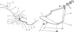
- FIG. 1is a side view of the separate footrest support device attached to a standard task chair.
- FIG. 2is an orthographic view of the separate footrest support device.
- FIG. 3is an exploded orthographic view of the separate footrest support device
- FIG. 4is a top view of the separate footrest support device.
- FIG. 5is a side view of the device with the seat in an upright, forward-tilt position.
- FIG. 6is a side view of the device with the seat in semi-reclined position.
- FIG. 7is a side view of the device with the seat in full reclined position.
- FIG. 8is an orthographic view of the device with the seat in reclined position.
- FIG. 9is a top view of the device with the seat in reclined position.
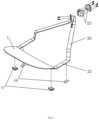
- FIG. 10is side view of the device with an alternative base
- FIG. 11is a top view of the device with an alternative base
- FIG. 12is an orthographic view of the device with an alternative base
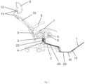
- FIG. 13is a side view of the device with an alternative base with a cable and pulley-based mechanism linkage that rotates the footplate automatically as the seat is raised or lowered
- FIG. 14is a side view of the device with an alternative base with a mechanism linkage that has rotated the footplate flush with the ground plane when the seat is raised
- FIG. 15is a simplified side view of the upper portion of a chair and seat angle adjustment mechanism in an upright position
- FIG. 16is a simplified orthographic detail view of a seat angle adjustment mechanism incorporating a torsion spring and seat angle actuator in an upright orientation
- the components of the Automated Task Chairinclude some or all of the following:
Landscapes
- Health & Medical Sciences (AREA)
- Dentistry (AREA)
- General Health & Medical Sciences (AREA)
- Chairs For Special Purposes, Such As Reclining Chairs (AREA)
Abstract
Description
- Seat base means to support the seat structure
- Footplate means to support the user's feet and legs
- Seat vertical axis means to raise or lower the entire seat structure.
- Seat base vertical axis actuator means to raise or lower the seat
- Seat angle adjustment mechanism means to change the angle of the seat
- Seat angle adjustment mechanism actuator means to change the angle of the seat
- Seat pan means to support the user's bottom/pelvis
- Armrest means to support the user's arms
- Armrest actuator means to raise or lower the arm support
- Seat back means to support the user's back
- Headrest means to support the user's head
- Headrest adjustment means to change the headrest position
- Headrest angle actuator means to change the headrest angle
- Headrest height actuator means to change the headrest height
- Footplate adjustment mechanism to change the footplate position
- Footplate actuator to change the footplate position and/or angle
- Sensor means to measure the position of relative seat components
- Sensor means to measure the pressure of the user's body at various points as it contacts the seating surfaces
- Control system means to receive data from the sensors, run programs and provide powered and/or automated movements by controlling the different actuators in the ATC
- Control system means integrated into chair
- Control system means integrated into device that is separate from chair
- Control system integrated into smart device, e.g., mobile phone, computer
- Control system integrated into wearable device
Claims (12)
Priority Applications (1)
| Application Number | Priority Date | Filing Date | Title |
|---|---|---|---|
| US18/093,923US12310502B2 (en) | 2023-01-06 | 2023-01-06 | Automated task chair |
Applications Claiming Priority (1)
| Application Number | Priority Date | Filing Date | Title |
|---|---|---|---|
| US18/093,923US12310502B2 (en) | 2023-01-06 | 2023-01-06 | Automated task chair |
Publications (2)
| Publication Number | Publication Date |
|---|---|
| US20240225287A1 US20240225287A1 (en) | 2024-07-11 |
| US12310502B2true US12310502B2 (en) | 2025-05-27 |
Family
ID=91762357
Family Applications (1)
| Application Number | Title | Priority Date | Filing Date |
|---|---|---|---|
| US18/093,923ActiveUS12310502B2 (en) | 2023-01-06 | 2023-01-06 | Automated task chair |
Country Status (1)
| Country | Link |
|---|---|
| US (1) | US12310502B2 (en) |
Families Citing this family (2)
| Publication number | Priority date | Publication date | Assignee | Title |
|---|---|---|---|---|
| US12226031B2 (en)* | 2022-01-27 | 2025-02-18 | The Texas A&M University System | Deployable backrest, footrail and anti-fatigue mat ergonomic office stool |
| US20230397733A1 (en)* | 2022-06-10 | 2023-12-14 | Anthro Form, Llc | Chair or seat assembly with sensor and illumination |
Citations (39)
| Publication number | Priority date | Publication date | Assignee | Title |
|---|---|---|---|---|
| US503246A (en)* | 1893-08-15 | Foot-rest for rocking-chairs | ||
| US694538A (en)* | 1901-04-02 | 1902-03-04 | Walton A Eddy | Foot-rest attachment for chairs. |
| US2524187A (en)* | 1946-01-05 | 1950-10-03 | Clarence M Boles | Roving seat for barber and similar chairs |
| US2620863A (en)* | 1949-07-26 | 1952-12-09 | John E Cooper | Dental stool extension for feet and motor control support |
| US3642320A (en)* | 1970-01-28 | 1972-02-15 | Duracraft Boats Inc | Vertically adjustable boat seat |
| US3820844A (en)* | 1973-04-30 | 1974-06-28 | Den Tal Ez Mfg Co | Step attachment for a dental stool |
| US4597356A (en)* | 1985-02-07 | 1986-07-01 | Mccaghren Charles P | Boat motor control platform for use with fisherman's chair |
| US4767160A (en)* | 1985-02-18 | 1988-08-30 | Mengshoel Hans Chr | Device for use in a kneeling-like sitting position |
| US4768831A (en)* | 1985-06-04 | 1988-09-06 | Bohusgruppen Ett Samhallsforetag | Arrangement for an operator's seat with a foot control |
| US5174631A (en)* | 1991-10-04 | 1992-12-29 | Schaevitz Lester P | Footrest and stabilizer |
| US5255957A (en)* | 1988-12-13 | 1993-10-26 | Peter Opsvik | Arrangement in a chair, for example a combined chair |
| US5765910A (en)* | 1993-08-05 | 1998-06-16 | Larkin; Stephen F. | Programmed motion work station |
| US20020043841A1 (en)* | 2000-07-21 | 2002-04-18 | Sitting Snc De Bordin Giacinto E Mauro | Ergonomic chair-armchair structure, particularly for office, of the type equipped with adjustable kidneyrest and headrest |
| US20030025374A1 (en)* | 2001-08-02 | 2003-02-06 | Edward Moore | Chair |
| US20030173808A1 (en)* | 2000-06-17 | 2003-09-18 | Hans Ruckstadter | Ergonomic office chair with an extending foot |
| US6634716B2 (en)* | 2000-10-17 | 2003-10-21 | Armin Sander | Office chair |
| US6648417B1 (en)* | 2001-06-13 | 2003-11-18 | Iceberg Enterprises, Llc | Auxiliary footrest for chair |
| US7032976B2 (en)* | 2004-03-01 | 2006-04-25 | Iou Jia Industrial Co., Ltd. | Stool apparatus for chair |
| US20060131942A1 (en)* | 2004-11-24 | 2006-06-22 | Humanscale Corporation | Delayed gas spring chair |
| US7198329B1 (en)* | 2003-10-23 | 2007-04-03 | Larson John E | Height adjustable work chair |
| US7341310B1 (en)* | 2005-06-24 | 2008-03-11 | Betty Ross | Office chair with automated height adjustment |
| US7452034B2 (en)* | 2006-12-27 | 2008-11-18 | Duoback Korea Co., Ltd. | Foot supporting apparatus of a chair |
| CN101332024A (en)* | 2008-07-30 | 2008-12-31 | 无锡佳思比科技有限公司 | Chair for correcting sitting posture |
| US8025334B2 (en)* | 2006-03-24 | 2011-09-27 | Herman Miller, Inc. | Piece of furniture |
| US20140103688A1 (en)* | 2011-06-09 | 2014-04-17 | Haworth, Inc. | Forward sliding reclining chair |
| US20150257960A1 (en)* | 2014-03-11 | 2015-09-17 | Rafael Barajas Reyes | Hydraulic Chair with Positioning Apparatus |
| US9149678B2 (en)* | 2007-05-08 | 2015-10-06 | Chair Trainer Ltd. | Exercise apparatus for retrofitting to swivel chairs on castors |
| US9642465B1 (en)* | 2016-07-28 | 2017-05-09 | Bright Company Inc. | Foot and leg support device for a chair |
| US20170197534A1 (en)* | 2014-07-25 | 2017-07-13 | Hyundai Dymos Incorporated | Footrest apparatus |
| US9848705B2 (en)* | 2015-07-28 | 2017-12-26 | Stabilus Gmbh | Electrically adjustable office chair |
| US9884200B2 (en)* | 2008-03-10 | 2018-02-06 | Neuronetics, Inc. | Apparatus for coil positioning for TMS studies |
| US10219625B2 (en)* | 2015-07-28 | 2019-03-05 | Stabilus Gmbh | Piece of furniture and adjusting assembly, in particular for adjusting a back of a chair |
| US10405666B1 (en)* | 2017-12-22 | 2019-09-10 | Scott A. Reus | Reconfigurable chair system |
| US10653242B2 (en)* | 2018-09-02 | 2020-05-19 | Ace Casual Limited | Racing gaming chair |
| US10772432B2 (en)* | 2016-07-28 | 2020-09-15 | Bright Company Inc. | Foot and leg support device for a chair |
| US11045002B1 (en)* | 2019-01-23 | 2021-06-29 | B&Z Productions, LLC | Quick-release footrest device |
| US11129480B2 (en)* | 2018-08-31 | 2021-09-28 | Fama Sofas, S.L.U. | Footrest for chair and armchair |
| US11160382B2 (en)* | 2018-03-02 | 2021-11-02 | Reid Beloff | Chair support assembly and related methods of use |
| US20230232993A1 (en)* | 2022-01-27 | 2023-07-27 | The Texas A&M University System | Deployable backrest, footrail and anti-fatigue mat ergonomic office stool |
- 2023
- 2023-01-06USUS18/093,923patent/US12310502B2/enactiveActive
Patent Citations (39)
| Publication number | Priority date | Publication date | Assignee | Title |
|---|---|---|---|---|
| US503246A (en)* | 1893-08-15 | Foot-rest for rocking-chairs | ||
| US694538A (en)* | 1901-04-02 | 1902-03-04 | Walton A Eddy | Foot-rest attachment for chairs. |
| US2524187A (en)* | 1946-01-05 | 1950-10-03 | Clarence M Boles | Roving seat for barber and similar chairs |
| US2620863A (en)* | 1949-07-26 | 1952-12-09 | John E Cooper | Dental stool extension for feet and motor control support |
| US3642320A (en)* | 1970-01-28 | 1972-02-15 | Duracraft Boats Inc | Vertically adjustable boat seat |
| US3820844A (en)* | 1973-04-30 | 1974-06-28 | Den Tal Ez Mfg Co | Step attachment for a dental stool |
| US4597356A (en)* | 1985-02-07 | 1986-07-01 | Mccaghren Charles P | Boat motor control platform for use with fisherman's chair |
| US4767160A (en)* | 1985-02-18 | 1988-08-30 | Mengshoel Hans Chr | Device for use in a kneeling-like sitting position |
| US4768831A (en)* | 1985-06-04 | 1988-09-06 | Bohusgruppen Ett Samhallsforetag | Arrangement for an operator's seat with a foot control |
| US5255957A (en)* | 1988-12-13 | 1993-10-26 | Peter Opsvik | Arrangement in a chair, for example a combined chair |
| US5174631A (en)* | 1991-10-04 | 1992-12-29 | Schaevitz Lester P | Footrest and stabilizer |
| US5765910A (en)* | 1993-08-05 | 1998-06-16 | Larkin; Stephen F. | Programmed motion work station |
| US20030173808A1 (en)* | 2000-06-17 | 2003-09-18 | Hans Ruckstadter | Ergonomic office chair with an extending foot |
| US20020043841A1 (en)* | 2000-07-21 | 2002-04-18 | Sitting Snc De Bordin Giacinto E Mauro | Ergonomic chair-armchair structure, particularly for office, of the type equipped with adjustable kidneyrest and headrest |
| US6634716B2 (en)* | 2000-10-17 | 2003-10-21 | Armin Sander | Office chair |
| US6648417B1 (en)* | 2001-06-13 | 2003-11-18 | Iceberg Enterprises, Llc | Auxiliary footrest for chair |
| US20030025374A1 (en)* | 2001-08-02 | 2003-02-06 | Edward Moore | Chair |
| US7198329B1 (en)* | 2003-10-23 | 2007-04-03 | Larson John E | Height adjustable work chair |
| US7032976B2 (en)* | 2004-03-01 | 2006-04-25 | Iou Jia Industrial Co., Ltd. | Stool apparatus for chair |
| US20060131942A1 (en)* | 2004-11-24 | 2006-06-22 | Humanscale Corporation | Delayed gas spring chair |
| US7341310B1 (en)* | 2005-06-24 | 2008-03-11 | Betty Ross | Office chair with automated height adjustment |
| US8025334B2 (en)* | 2006-03-24 | 2011-09-27 | Herman Miller, Inc. | Piece of furniture |
| US7452034B2 (en)* | 2006-12-27 | 2008-11-18 | Duoback Korea Co., Ltd. | Foot supporting apparatus of a chair |
| US9149678B2 (en)* | 2007-05-08 | 2015-10-06 | Chair Trainer Ltd. | Exercise apparatus for retrofitting to swivel chairs on castors |
| US9884200B2 (en)* | 2008-03-10 | 2018-02-06 | Neuronetics, Inc. | Apparatus for coil positioning for TMS studies |
| CN101332024A (en)* | 2008-07-30 | 2008-12-31 | 无锡佳思比科技有限公司 | Chair for correcting sitting posture |
| US20140103688A1 (en)* | 2011-06-09 | 2014-04-17 | Haworth, Inc. | Forward sliding reclining chair |
| US20150257960A1 (en)* | 2014-03-11 | 2015-09-17 | Rafael Barajas Reyes | Hydraulic Chair with Positioning Apparatus |
| US20170197534A1 (en)* | 2014-07-25 | 2017-07-13 | Hyundai Dymos Incorporated | Footrest apparatus |
| US9848705B2 (en)* | 2015-07-28 | 2017-12-26 | Stabilus Gmbh | Electrically adjustable office chair |
| US10219625B2 (en)* | 2015-07-28 | 2019-03-05 | Stabilus Gmbh | Piece of furniture and adjusting assembly, in particular for adjusting a back of a chair |
| US9642465B1 (en)* | 2016-07-28 | 2017-05-09 | Bright Company Inc. | Foot and leg support device for a chair |
| US10772432B2 (en)* | 2016-07-28 | 2020-09-15 | Bright Company Inc. | Foot and leg support device for a chair |
| US10405666B1 (en)* | 2017-12-22 | 2019-09-10 | Scott A. Reus | Reconfigurable chair system |
| US11160382B2 (en)* | 2018-03-02 | 2021-11-02 | Reid Beloff | Chair support assembly and related methods of use |
| US11129480B2 (en)* | 2018-08-31 | 2021-09-28 | Fama Sofas, S.L.U. | Footrest for chair and armchair |
| US10653242B2 (en)* | 2018-09-02 | 2020-05-19 | Ace Casual Limited | Racing gaming chair |
| US11045002B1 (en)* | 2019-01-23 | 2021-06-29 | B&Z Productions, LLC | Quick-release footrest device |
| US20230232993A1 (en)* | 2022-01-27 | 2023-07-27 | The Texas A&M University System | Deployable backrest, footrail and anti-fatigue mat ergonomic office stool |
Also Published As
| Publication number | Publication date |
|---|---|
| US20240225287A1 (en) | 2024-07-11 |
Similar Documents
| Publication | Publication Date | Title |
|---|---|---|
| US10213024B2 (en) | Office, work and leisure chair and retrofit kit for a chair or a seat surface for causing subliminal movements of the person sitting thereon | |
| US12310502B2 (en) | Automated task chair | |
| US10602846B2 (en) | Method for using a chair providing uplifting force to the user | |
| US11471345B2 (en) | Adjustable ergonomic chair | |
| US7806479B2 (en) | Seat with adjustable dynamic joint | |
| US8944977B2 (en) | Combination ergonomic task chair and exercise device | |
| KR20110117193A (en) | Method and apparatus for correcting posture dynamically | |
| EP2156766B1 (en) | Chair (variants) | |
| JP6189861B2 (en) | Desk configuration | |
| JP7738087B2 (en) | Ergonomic Motion Chair | |
| EP2632297B1 (en) | A furniture unit to sit-on | |
| Festervoll | Office seating and movement | |
| WO2007001207A1 (en) | Superposable seat | |
| JP2002336095A (en) | Chair | |
| EP2575551B1 (en) | Automatic tilting of a support surface on a support device | |
| KR102361944B1 (en) | Backrest chair with back-down seat plate structure with front sliding tilting and rear twisting functions | |
| EP3796813B1 (en) | Sitting furniture | |
| CN221382969U (en) | Ergonomic sports seats | |
| RU153742U1 (en) | KINETIC CHAIR | |
| KR102540993B1 (en) | Chair with adjustable seat angle | |
| KR200180804Y1 (en) | Standing typed chair | |
| JP2024535042A (en) | Apparatus and method for adapting the contour of a back element to a person's posture - Patents.com | |
| CA3093618A1 (en) | Dynamic seating plate | |
| US20200037763A1 (en) | Adjustable home/office balance ball chair | |
| AU2018226511A1 (en) | Adjustable home/office balance ball chair |
Legal Events
| Date | Code | Title | Description |
|---|---|---|---|
| FEPP | Fee payment procedure | Free format text:ENTITY STATUS SET TO UNDISCOUNTED (ORIGINAL EVENT CODE: BIG.); ENTITY STATUS OF PATENT OWNER: SMALL ENTITY | |
| FEPP | Fee payment procedure | Free format text:ENTITY STATUS SET TO SMALL (ORIGINAL EVENT CODE: SMAL); ENTITY STATUS OF PATENT OWNER: SMALL ENTITY | |
| STPP | Information on status: patent application and granting procedure in general | Free format text:NON FINAL ACTION MAILED | |
| STPP | Information on status: patent application and granting procedure in general | Free format text:NON FINAL ACTION MAILED | |
| STPP | Information on status: patent application and granting procedure in general | Free format text:FINAL REJECTION MAILED | |
| STPP | Information on status: patent application and granting procedure in general | Free format text:DOCKETED NEW CASE - READY FOR EXAMINATION | |
| STPP | Information on status: patent application and granting procedure in general | Free format text:NOTICE OF ALLOWANCE MAILED -- APPLICATION RECEIVED IN OFFICE OF PUBLICATIONS | |
| AS | Assignment | Owner name:PUSH PRODUCT DESIGN, LLC, ALABAMA Free format text:ASSIGNMENT OF ASSIGNORS INTEREST;ASSIGNORS:PHILLIPS, FOSTER DANIEL;WILSON, LARRY TODD;COOPER, LLOYD BOWERS;REEL/FRAME:070958/0242 Effective date:20250425 | |
| STCF | Information on status: patent grant | Free format text:PATENTED CASE |