US12310356B2 - Organ container with oxygenation option - Google Patents
Organ container with oxygenation optionDownload PDFInfo
- Publication number
- US12310356B2 US12310356B2US17/015,443US202017015443AUS12310356B2US 12310356 B2US12310356 B2US 12310356B2US 202017015443 AUS202017015443 AUS 202017015443AUS 12310356 B2US12310356 B2US 12310356B2
- Authority
- US
- United States
- Prior art keywords
- basin
- oxygen
- organ
- tubing
- perfusate
- Prior art date
- Legal status (The legal status is an assumption and is not a legal conclusion. Google has not performed a legal analysis and makes no representation as to the accuracy of the status listed.)
- Active, expires
Links
Images


Classifications
- A—HUMAN NECESSITIES
- A01—AGRICULTURE; FORESTRY; ANIMAL HUSBANDRY; HUNTING; TRAPPING; FISHING
- A01N—PRESERVATION OF BODIES OF HUMANS OR ANIMALS OR PLANTS OR PARTS THEREOF; BIOCIDES, e.g. AS DISINFECTANTS, AS PESTICIDES OR AS HERBICIDES; PEST REPELLANTS OR ATTRACTANTS; PLANT GROWTH REGULATORS
- A01N1/00—Preservation of bodies of humans or animals, or parts thereof
- A01N1/10—Preservation of living parts
- A01N1/14—Mechanical aspects of preservation; Apparatus or containers therefor
- A01N1/142—Apparatus
- A01N1/143—Apparatus for organ perfusion
Definitions
- organ or tissue perfusion apparatusesthat are capable of sustaining and/or restoring viability of organs or tissue and preserving organs or tissue for diagnosis, treatment, storage, and/or transport.
- organas used herein should be understood to mean organ and/or tissue unless otherwise specified.
- organ perfusion apparatusesIt is an objective of organ perfusion apparatuses to support aerobic metabolism such that the organ remains viable before being used for research, diagnosis, treatment, or transplantation. Often the organ must be stored and/or transported between facilities. A goal of sustaining and restoring organs during perfusion is to reduce ischemia and reperfusion injury. The increase in storage periods in a normal or near normal functioning state also provides certain advantages. For example, organs can be transported greater distances and there is increased time for testing, treatment, and evaluation of the organs.
- U.S. Pat. Nos. 9,357,767; 9,357,766; and 9,723,830disclose, for example, a perfusion apparatus that employs a disposable perfusion circuit within which the organ may be stored during perfusion.
- This circuitcomprises a basin that may serve as a receptacle for an organ cradle on which the organ may be placed and for a perfusate bath that may be formed around the organ.
- Inner and outer lidsmay be used to close the basin during perfusion, and the basin may fit within a coolant container so that both the perfusate bath and the organ are brought to hypothermic temperatures.
- hypothermic temperatures during transportation and perfusiongreatly improves organ preservation by decreasing oxygen demands and metabolic activity of the organ, it does not completely eliminate them.
- a corresponding lack of oxygencan drive the cells of the organ to anaerobic activity, which causes a buildup of lactate and mitochondrial uncoupling and depleted adenosine triphosphate (“ATP”) stores, and thereby leads to the release of toxic molecules such as radical oxygen species, inflammatory cytokines, and lactate.
- ATPadenosine triphosphate
- the firstis the amount of time required to adequately oxygenate the perfusate solution. Time during organ transplantation is at a premium, so an oxygenator device should be able to rapidly oxygenate the perfusate solution. Further, hospitals and clinics may have also acquired or purchased a substantial amount of disposables to be used during perfusion, and may be hesitant to discard these likely expensive disposables to oxygenate the perfusate solution. There is thus also a need for a device with an oxygenation option that works with existing equipment and disposables to oxygenate the perfusate solution.
- a device with an oxygenation optionmay be for oxygenating a perfusate solution to be perfused through an organ or tissue.
- This devicemay comprise an inlet configured to receive oxygen from an oxygen supply, and it may also comprise tubing connected to the inlet, the tubing including a plurality of holes by which the received oxygen may exit the tubing.
- the oxygenation devicemay also comprise a top portion from which the inlet extends, and it may further include a plurality of holders extending below the top portion so as to secure the tubing below the top portion.
- each of the plurality of holdersmay also include (i) a vertical portion extending substantially perpendicular to the top portion and (ii) an angled portion extending at an outward angle relative to the vertical portion.
- the tubingmay be secured by the angled portions of the plurality of holders.
- the plurality of holdersmay secure the tubing in a loop having a circumference sufficient to encircle the organ or tissue in use, and a majority of this loop may be substantially parallel to a virtual plane formed by the top portion.
- the oxygenation devicemay be configured to be attached to an organ perfusion circuit, and a top portion of the oxygenation device, from which the inlet extends, may constitute a lid for a basin of the organ perfusion circuit that is configured to hold the organ or tissue during perfusion.
- the tubingmay be fixed below the top portion so that, when the oxygenation device is placed on the basin, the tubing and the plurality of holes therein may be submerged in a bath of the perfusate solution in the basin.
- the tubingmay be secured in position by a plurality of holders so that, when the oxygenation device is placed on the basin, the tubing does not interfere with an organ cradle locatable within the basin.
- the oxygenation devicemay further comprise a hydrophobic vent in the top portion, the vent being configured to limit pressure increase within the basin when the oxygenation device is placed on the basin and oxygen flows from the plurality of holes in the tubing to the perfusate solution.
- the holesmay be arranged in a plurality of groupings spaced apart along a length of the tubing.
- each of the groupingsmay comprise a plurality of the holes spaced apart around a circumference of the tubing.
- each pair of the plurality of groupingsmay be spaced apart by 34.79 mm of the tubing, and an average diameter of the plurality of holes may be between 0.10 mm and 0.18 mm.
- This methodmay include placing the oxygenation device on a basin of an organ perfusion circuit so that the tubing and the holes therein are submerged within a bath of the perfusate solution within the basin; connecting the inlet of the oxygenation device to an oxygen supply; and administering oxygen from the oxygen supply, through the inlet, through the holes in the tubing, and into the perfusate bath so as to increase oxygen concentration of the perfusate solution constituting the bath.
- the methodmay also include a step of administering the oxygen from the oxygen source at a rate of about 10 liters per minute for at least 10 minutes.
- the placing stepmay further include, prior to the placing step, removing a lid of the basin.
- the placing stepmay thus replace the lid of the basin with the oxygenation device.
- the methodmay yet further include steps of discontinuing administration of the oxygen from the oxygen supply, and then placing the organ or tissue in the basin of the organ perfusion circuit.
- the oxygenmay alternatively be administered while the organ or tissue is being perfused in the organ perfusion circuit.
- the oxygenation structuresbe located within the basin of the organ container itself.
- advantageslike the ability to close an outer lid on top of the basin of the organ container during oxygen administration and especially the ability to provide oxygen during liver perfusion, this could reduce the number of disposables that a hospital or clinician must maintain on hand.
- an organ containerfor storing an organ or tissue and configured to be inserted into an apparatus for at least one of perfusion and transport of the organ or tissue.
- the organ containermay include a basin configured to hold the organ or tissue and a perfusate bath, and it may also include tubing that (i) is connectable to a source of oxygen, (ii) includes a plurality of holes by which the oxygen may exit the tubing, and (iii) is located within the basin so as to be submerged within the perfusate bath present during the perfusion or transport of the organ or tissue.
- the organ containermay also include at least one holder within the basin to secure the tubing below a surface of the perfusate bath.
- the at least one holdermay be a plurality of the holders, and each of the plurality of holders may: (i) extend toward a bottom of the basin from an upper rim of the basin; (ii) descend along an internal wall of the basin; and (iii) include a hole through which the tubing passes.
- the at least one holdermay secure the tubing in a loop that encircles the organ or tissue in use.
- the organ containermay also include a connector within the basin, and the connector may be configured to connect and disconnect the tubing with an oxygen line that extends outside of the basin.
- the connectormay be connected to the tubing by another tubing and a T-fitting.
- the connectormay be a Luer Lock fitting.
- the holes of the tubingmay be arranged in a plurality of groupings spaced apart along a length of the tubing.
- the groupingsmay comprise a plurality of the holes spaced apart around a circumference of the tubing.
- each pair of the plurality of groupingsmay be spaced apart by about 34.79 mm of the tubing, and an average diameter of each of the plurality of holes may be between 0.10 mm and 0.18 mm.
- the oxygenation devicemay further include a hydrophobic vent in each lid of the basin, the vent in use limiting pressure increase within the basin.
- the apparatusmay include the organ container discussed above, and it may include an oxygen line configured to convey oxygen from a source of oxygen to the tubing.
- a first end of the oxygen linemay be within the basin of the organ container, and a second end of the oxygen line may be outside the basin.
- the apparatusmay further include a first external lid configured to cover the basin when closed and a second external lid, adjacent the first external lid, and configured to cover other components of the apparatus when closed.
- the second end of the oxygen linemay be exposed even when the first external lid is closed.
- the apparatusmay further include an anti-bacterial filter at the second end of the oxygen line.
- This methodmay include a step of introducing the perfusate solution into the organ container discussed above so as to form in the basin of the organ container a perfusate bath within which the tubing inside the basin is submerged.
- the methodmay also include steps of connecting the tubing to a source of oxygen and administering oxygen from the source, through the holes in the tubing, and into the perfusate bath so as to increase oxygen concentration of perfusate solution constituting the bath.
- the methodmay further include a step of administering the oxygen from the oxygen source at a rate of about 10 liters per minute for at least 10 minutes.
- FIG. 1is a cross-sectional view of an organ perfusion apparatus according to one or more embodiments of the disclosure.
- FIG. 2is a cross-sectional view of the combined coolant container, basin, and cradle of the organ perfusion apparatus of FIG. 1 .
- FIG. 3is a top perspective view of a device with oxygenation option according to one or more embodiments of the disclosure.
- FIG. 4is a bottom perspective view of the oxygenation device of FIG. 3 .
- FIG. 5is a top plan view of the oxygenation device of FIG. 3 .
- FIG. 6is a bottom plan view of the oxygenation device of FIG. 3 .
- FIG. 7is a side elevation view of the oxygenation device of FIG. 3 .
- FIG. 8is another side elevation view of the oxygenation device of FIG. 3 .
- FIG. 9is an enlarged view of a portion IX of the tubing shown in FIG. 8 .
- FIG. 10is a cross-sectional view of the tubing taken along line X-X in FIG. 9 .
- FIG. 11shows a process of using the oxygenation device of FIG. 3 .
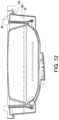
- FIG. 12is a cross-sectional view of the oxygenation device of FIG. 3 placed on a basin of an organ perfusion circuit.
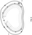
- FIG. 13shows a top plan view of a basin of an organ container according to one or more embodiments of the disclosure.
- FIG. 14shows a top plan view of an organ perfusion device configured to receive the organ container of FIG. 13 .
- FIG. 15shows another top plan view of the organ perfusion device of FIG. 14 .
- FIG. 16shows a process of using the organ container of FIG. 13 .
- FIGS. 1 and 2show an exemplary perfusion apparatus 10 for an organ.
- the organmay preferably be a liver, kidney, heart, lung, or intestine, but it may be any human or animal, natural or engineered, healthy, injured, or diseased organ or tissue.
- the apparatus 10may include outer lids 20 , 22 and an organ container including a basin 30 (see FIG. 2 ) in which the organ may be placed.
- the basin 30may hold a removable cradle 60 , which may preferably include a surface 60 a on which the organ may be disposed when the organ is in the apparatus 10 .
- the basin 30 and/or the cradle 60may preferably be configured to allow a perfusate bath of perfusate solution such as VASOSOL® to be contained around the organ.
- the basin 30may preferably be disposed within an insulating coolant container 50 that may contain cold materials such as ice, ice water, brine, or the like.
- Coolant container 50may be permanently or removably attached to, or an integral, monolithic part of, apparatus 10 .
- the organmay be disposed within the cradle 60 , which may be disposed within the basin 30 , which may be disposed within the coolant container 50 , as shown in FIG. 2 .
- the arrangement of the coolant container 50 , basin 30 , and cradle 60preferably provides a configuration that provides cooling for the organ without the contents of coolant container 50 contacting the organ or the cradle 60 .
- the coolant container 50is described herein as containing ice or ice water, any suitable cooling medium can be used.
- an inner lid 66 and an outer lid 67may be provided on an upper surface of the basin 30 .
- the inner lid 66may be sized to come into close proximity to the perimeter top surface of the cradle 60 to help maintain stability of the organ in the event of mechanical impact and shock during transport. More specifically, the inner lid 66 may have a downwardly protruding extension 66 a that matches a circumferential shape of a peripheral ridge 60 b of the cradle 60 and is configured to contact the peripheral ridge 60 b and help hold the cradle 60 in position.
- the lids 66 and 67may create a substantially fluid-tight seal with the basin 30 , and they can prevent contamination.
- the lids 66 and 67may also provide for a redundant airtight seal should the seal from either lid 66 or 67 fail.
- Both the inner lid 66 and the outer lid 67may preferably contain an air vent, e.g., a porous hydrophobic membrane, that allows for gas transfer in order to maintain pressure equilibrium.
- all components of the apparatus 10 that come into contact with perfusate solution and/or the organare disposable and/or easily replaced.
- These componentsmay include the basin 30 , the organ cradle 60 , and the lids 66 and 67 , which may constitute parts of a disposable organ perfusion circuit.
- this disposable organ perfusion circuitmay be placed within the non-disposable portion of the apparatus 10 , and the organ may be placed on the organ cradle 60 within the basin 30 . Because of the presence of the coolant container 50 , both the organ and the perfusate bath within the basin 30 are subjected to hypothermic temperatures. The perfusate solution may then be circulated through the disposable perfusion circuit and the organ.
- FIGS. 3 and 4show a device with an oxygenation option 100 in accordance with one or more aspects of the present disclosure.
- the device 100may be designed to work with the perfusion apparatus 10 to increase the oxygen concentration of the perfusate bath within the basin 30 .
- This device 100may generally be constituted by a main body 110 and oxygenation components 150 .
- the main body 110may in turn include a top portion 120 including, as shown in FIG. 5 , radially inner and outer portions 122 and 124 .
- the main body 110may also include, as shown in FIG. 6 , a bottom portion 130 projecting downward from the top portion 120 .
- the main body 110may be formed, for example, from clear polycarbonate plastic resin.
- the top portion 120may be, like the inner lid 66 , sized to correspond to the basin 30 . More specifically, a lower lip 126 (see FIG. 4 ) of the radially outer portion 124 of the top portion 120 may be sized so as to be received by an indentation 36 (see FIG. 2 ) in an upper surface of the basin 30 and thereby allow the oxygenation device 100 to constitute a lid for that basin in place of the inner lid 66 . Latches (not shown) on the basin 30 may be used to lock the oxygenation device 100 in place relative to the basin 30 . As shown in FIGS. 7 and 8 , the top portion 120 may be substantially planar.
- the overall shape of the top portion 120forms a virtual plane projecting into the pages of FIGS. 7 and 8 .
- the outer portion 124may be flat, whereas the inner portion 122 may be convex outward.
- a vent 128also provided within the top portion 120 may be a vent 128 (see FIGS. 5 and 6 ).
- the vent 128may include a porous hydrophobic membrane, which allows for gas transfer in order to maintain pressure equilibrium.
- the membrane of the vent 128may be an acrylic copolymer treated to render it hydrophobic and oleophobic, and the membrane may be attached and bonded to a non-woven nylon substrate.
- the membraneitself may have an average porosity of 0.45 microns, and it may repel and be resistant to oil, water, and organic solvents and be non-wettable by most low-surface-tension liquids. This stands in contrast to, say, a hydrophilic membrane that has a tendency to mix with or be wettable by such liquids.
- Around the perimeter of the vent 128may be provided an adhesive to secure the vent 128 to the remainder of the top portion 120 and thereby ensure that it remains attached thereto with a tight seal.
- the bottom portion 130may be formed in the space between the radially inner and outer portions 122 and 124 of the top portion 120 , and it may have a substantially triangular shape in cross-section. More specifically, a radially outer wall 132 (see FIG. 4 ) of the bottom portion 130 may extend downward substantially perpendicular to the virtual plane of the top portion 120 , and a radially inner wall 134 of the bottom portion 130 may extend downward from the top portion 120 at an angle inclined relative to the outer wall 132 . The walls 132 and 134 may meet at a vertex 136 , thereby ensuring that the main body 110 is able to create a substantially fluid-tight seal with the basin 30 and thereby prevent contamination.
- the bottom portion 130(and particularly the vertex 136 ) may, like the downwardly protruding extension 66 a of the inner lid 66 , also match the circumferential shape of the peripheral ridge 60 b of the cradle 60 , and it may thus likewise be configured to contact that peripheral ridge and help hold the cradle 60 and any organ thereon in position.
- the oxygenation components 150may in turn include, as shown in FIG. 7 , an oxygen inlet 160 , a T-fitting 162 , holders 170 , and tubing 180 .
- the oxygen inlet 160may be an oxygen barb projecting from a bridge portion 129 (see FIG. 5 ) that connects the radially inner and outer portions 122 and 124 of the top portion 120 .
- the oxygen inlet 160may be angled substantially perpendicular to the virtual plane of the top portion 120 to facilitate ease of use and to reduce the risk of kinking of the tube delivering oxygen to the inlet.
- the T-fitting 162may in turn be fluidly connected to the oxygen inlet 160 , and it may be formed below the bridge portion 129 in a gap 138 formed in the bottom portion 130 .
- the tubing 180may be fluidly connected to the T-fitting 162 , and it may be secured in position by the plurality of holders 170 .
- each of these holders 170may include an upper, vertical portion 172 secured to the bottom portion 130 of the main body 110 and projecting from the top portion 120 in a direction substantially perpendicular to the virtual vertical plane of the top portion 120 .
- the holders 170may secure the tubing 180 below the bottom portion 130 , and each of the holders 170 may also include an angled portion 174 that is angled outward relative to the vertical portion 172 .
- the angled portion 174may be angled relative to the vertical portion 172 by, say, 2.5 degrees, although other angles are possible.
- the angled portion 174 of each of the holders 170may include a hole through which the tubing 180 may pass. As discussed below, angling the angled portions 174 relative to the vertical portions 172 may help ensure that neither the holders 170 nor the tubing 180 interferes in use with the organ cradle 60 , any organ or vasculature thereon, or cannula that may be disposed within the basin 30 .
- the rounded ends of the angled portions 174at which the holes are located, may also ensure that there is no crashing or interference with the basin 30 during use.
- the tubing 180may be formed of aromatic polyether-based polyurethane, and it may be of sufficient length to encircle the bottom portion 130 and thus to encircle a perfused organ when the oxygenation device 100 serves as the lid for the basin 30 .
- the total length of the tubing 180may be equal to or about 1,054.10 mm, although other lengths are possible.
- FIG. 9shows an enlarged view of the portion IX of the tubing 180 shown in FIG. 8 , and as shown in this Figure, the tubing 180 may include a plurality of groupings 182 of holes 184 that may be spaced apart along the length of the tubing 180 by a distance 186 .
- the distance 186may be equal to or about 34.79 mm, although other distances are possible.
- 24 groupings 182may be formed in the tubing 180 , and as shown in FIG. 10 , which shows a cross-section of the tubing 180 at one of the groupings 182 , each grouping may include 5 holes 184 equally spaced around the circumference of the tubing 180 .
- the tubing 180may thus include a total of 120 holes 184 .
- Each of the holes 184may be formed in the tubing 180 by way of laser ablation. And each hole 184 may have a diameter of 0.10 mm to 0.18 mm, which has been shown to be well within the capability of the laser ablation process and repeatable.
- hollow fiber filtersmay be used to provide oxygen to the perfusate solution. Hollow fiber filters may prevent bubbling of the perfusate solution during the oxygenation process. But if the perfusate solution is not whole blood, this potential difference may be insufficient to justify the substantial increase in cost of hollow fiber filters relative to the tubing 180 .
- the above-described arrangement of the holes 184achieves a sufficiently short time to “bubble” and therefore saturate the perfusate solution of the perfusate bath with oxygen while maintaining a suitable cost.
- the holes 184ensure that the perfusate solution of the bath will be saturated within a timeframe of 10-15 minutes, which is acceptable for most clinics as surgical procedures taking place concurrently may take substantially longer.
- Other numbers of holes 184 and other sizes of those holesare possible; however, various considerations should be taken into account. More holes 184 of the same diameter, for example, may reduce the time required to fully saturate the perfusate solution.
- holes 184are also possible. They could be positioned linearly along the length of the tubing 180 , for example. However, the above-described arrangement with the groupings 182 , in which five holes 184 are spaced around the circumference of the tubing 180 , helps ensure that at least most of the holes 184 are placed below the surface of the perfusate in use. Equally spacing the groupings 182 by the distance 186 across the length of the tubing 182 may also help ensure that most of the perfusate solution is evenly exposed to oxygen gas, thereby preventing one region from being under-concentrated.
- FIG. 11shows a method by which the device with an oxygenation option 100 may be used with a perfusion apparatus, e.g., the perfusion apparatus 10 , to increase the dissolved oxygen content in the perfusate solution constituting a perfusate bath.
- the oxygenation device 100may be placed on the basin 30 . This arrangement is shown by cross-section in FIG. 12 . As shown in this Figure, the lower lip 126 of the oxygenation device 100 may be sized so as to correspond to the depression 36 in the top surface of the basin 30 .
- the holders 170may also secure the tubing 180 and the holes 184 therein low enough within the basin 30 to be submerged within the perfusate bath, a possible level of which is shown by 190 in FIG.
- the tubing 180may be located outside so as not to interfere with the organ cradle 60 , any organ or vasculature thereon, or any cannula in the assembled position shown in FIG. 12 .
- the oxygenation device 100may be secured to the basin 30 by way of the aforementioned latches.
- the oxygenation device 100may be connected to an external oxygen source.
- the oxygen sourceis not particularly limited. It may be, for example, an oxygen cylinder or a wall valve in a hospital or clinic setting.
- a user or users of the device 100may attach one end of an extension tube to the oxygen inlet 160 and another end of that tube to the oxygen source.
- oxygenmay be administered in a step 230 .
- oxygenmay be administered from the oxygen source at a rate at or about 10 liters per minute for at least 10 minutes, more preferably for at least 15 minutes, and even more preferably for at least 20 minutes.
- Other rates of oxygen floware possible, however.
- the oxygencould be administered from the oxygen source at a rate of 1, 2, or 3 liters per minute. But this may unacceptably lengthen the period of time required to fully saturate the perfusate solution of the perfusate bath.
- oxygen flow rates up to 20 liters per minute or moreare conceived.
- the oxygen administrationmay be discontinued and the oxygenation device 100 may be removed from the basin 30 at step 240 . Because the oxygenated perfusate is then open to atmosphere, the inner lid 66 may then preferably be placed on the basin 30 as soon as possible. The organ may then be placed within the basin 30 and perfused with the oxygenated perfusate solution. It is also conceivable that, once the administration of oxygen has been discontinued, there may be some delay in placing the organ within the basin 30 and beginning perfusion. It may therefore be necessary to oxygenate the perfusate solution again after a period of time so that the desirable oxygenation level can be maintained. Preferably this re-administration occurs prior to removal of the oxygenation device 100 from the basin 30 , as the device's sterility may become compromised once removed from the basin.
- the process 200 shown in FIG. 11thus provides a means by which to pre-charge with oxygen a perfusate solution prior to placement of an organ within the perfusion circuit and subsequent perfusion of that organ.
- the oxygenation device 100may not be removed from the basin 30 once pre-charging is complete, and it could thus serve as the lid of the basin during perfusion of the organ.
- the oxygenation device 100could also continue to oxygenate the perfusate during perfusion and/or transport of the organ. This oxygenation during perfusion could help maintain elevated oxygen levels in the perfusate throughout transport.
- a portable oxygen sourcewould likely be beneficial for this modification.
- the step 210 of the process 200may also be preceded by steps 205 and 207 .
- step 205following priming and cooling of the perfusion circuit, the inner lid 66 of the perfusion circuit may be removed to make space for the oxygenation device 100 . And in step 207 , the perfusate solution may be decanted into the basin 30 so as to form the perfusate bath.
- the device with an oxygenation option 100thus provides a mechanism by which to rapidly oxygenate a perfusate solution, thereby providing the above-described benefits of oxygen while avoiding the hazards associated with delays in the transplantation process. It also works with existing perfusion circuits, ensuring that these costly disposables need not be replaced by a clinic or hospital to obtain the benefits of oxygenation.
- the oxygenation components 150may constitute part of a separate oxygenation device 100 . But this need not be the case. Instead, and as shown in FIG. 13 , some or all of oxygenation components 350 may be integrated with the organ container.
- tubing 380which may be identical to any of the embodiments of the tubing 180 discussed previously, may be incorporated inside the basin 30 .
- This tubing 380may run generally along an internal wall 32 of the basin so as to encircle an organ or tissue placed within the basin.
- Holders 370may extend from a rim 34 of the basin 30 and hold the tubing 380 so that it is submerged within a perfusate bath in the basin during perfusion of the organ.
- These holders 370may generally descend along the internal wall 32 of the basin 30 , and like the holders 170 , they may each include a hole through which the tubing 380 may pass.
- a T-fitting 362which fluidly connects the tubing 380 to an oxygen source
- a connector 364upstream of the T-fitting 362 , that enables a practitioner to switch between bubble and surface oxygenation. More specifically, when upstream, oxygen line 390 and tubing 382 downstream of the connector 364 are connected at the connector 364 , input oxygen is routed to the tubing 380 , which may be submerged below the surface of the perfusate bath during perfusion of the organ. But when that connection is severed at the connector 364 , the input oxygen is administered within the basin 30 but above the surface of the perfusate bath.
- the connector 364may be a Luer Lock connector or 3-way stopcock.
- FIG. 14shows the oxygen line 390 , which may extend from the connector 364 and outside of the basin 30 .
- oxygenmay be supplied from an oxygen source (not shown).
- an anti-bacterial filter 394 for filtering the input oxygenmay be attached to the oxygen line 390 .
- this filter 394may be attached to the end 392 of the line.
- FIG. 15by virtue of the oxygen line 390 extending away from the basin 30 , oxygen may still be input to that line 390 with the outer lid 20 closed.
- FIG. 16shows a method 400 by which a perfusion apparatus, e.g., the perfusion apparatus 10 , equipped with an organ container including a basin 30 having the oxygenation components 350 may be used to increase the dissolved oxygen content in the perfusate solution constituting a perfusate bath.
- the oxygen line 390may be connected to an oxygen source, e.g., an external oxygen source, by way of the anti-bacterial filter 394 .
- this connectionoccurs after an amount, e.g., 3 L, of Vasosol solution has been added to the basin 30 so as to form the perfusate bath therein and both inner lid 66 and outer lid 67 are placed on the basin 30 so as to seal it from the external environment.
- oxygenis administered to the oxygen line 390 at a rate of preferably 10 L/min. Because the oxygen line 390 and the tubing 382 are connected by way of the connector 364 , this input oxygen is supplied to the perfusate bath by way of the submerged tubing 380 . This bubble oxygenation may continue for at least 10 minutes, and more preferably for at least 20 minutes, during which time the clinician may be preparing the organ for machine perfusion. Both lids 66 , 67 may remain closed during the administration of oxygen by way of the tubing 380 .
- both inner and outer lids 66 , 67may be removed so as to open the basin 30 .
- a sterile drapemay optionally be applied after opening the outer lid 67 and before opening the inner lid 66 .
- the oxygen line 390 and the tubing 382may be disconnected at the connector 364 .
- Oxygen input to the oxygen line 390may also be reduced, preferably to at or about 2 L/min, and this reduced oxygen may then be administered to the surface of the perfusate bath by way of the open connector 364 .
- the organmay then be introduced into the basin 30 and perfusion of that organ may begin.
- the inner lid 66may then be placed on the basin 30 as soon as possible thereafter, and once perfusion flows have stabilized, the sterile drape may be removed and the outer lid 67 also placed on the basin 30 .
- the outer lid 20is closed during this surface oxygenation so as to help maintain a hypothermic environment for the perfused organ.
- Surface oxygenationmay continue until a transport step 440 , in which the oxygen line 390 may be disconnected from the external oxygen source and the outer lid 22 , which covers the end 390 of the oxygen line, may also be closed.
- surface oxygenationmay be resumed at step 450 . This may be accomplished by opening outer lid 22 , connecting the oxygen line 390 to another oxygen source by way of the anti-bacterial filter 394 , and then administering oxygen at a reduced flow rate, preferably 2 L/min, until implantation of the organ.
- Moving oxygenation components 350 into the basin 30thus provides various differences in functionality relative to the components 150 constituting part of a separate oxygenation device 100 .
- bubble oxygenationmay be achieved without the presence of the device 100 .
- placing the end 392 of the oxygen line 390 outside the basin 30 while including the connector 364 in that basinenables the option to continue oxygenation during perfusion by way of the interface between the perfusion bath and the gas above.
Landscapes
- Life Sciences & Earth Sciences (AREA)
- Health & Medical Sciences (AREA)
- Engineering & Computer Science (AREA)
- Dentistry (AREA)
- General Health & Medical Sciences (AREA)
- Wood Science & Technology (AREA)
- Zoology (AREA)
- Environmental Sciences (AREA)
- Agricultural Chemicals And Associated Chemicals (AREA)
- Packages (AREA)
Abstract
Description
Claims (14)
Priority Applications (1)
| Application Number | Priority Date | Filing Date | Title |
|---|---|---|---|
| US17/015,443US12310356B2 (en) | 2019-09-13 | 2020-09-09 | Organ container with oxygenation option |
Applications Claiming Priority (2)
| Application Number | Priority Date | Filing Date | Title |
|---|---|---|---|
| US201962900131P | 2019-09-13 | 2019-09-13 | |
| US17/015,443US12310356B2 (en) | 2019-09-13 | 2020-09-09 | Organ container with oxygenation option |
Publications (2)
| Publication Number | Publication Date |
|---|---|
| US20210076668A1 US20210076668A1 (en) | 2021-03-18 |
| US12310356B2true US12310356B2 (en) | 2025-05-27 |
Family
ID=73014583
Family Applications (1)
| Application Number | Title | Priority Date | Filing Date |
|---|---|---|---|
| US17/015,443Active2041-12-28US12310356B2 (en) | 2019-09-13 | 2020-09-09 | Organ container with oxygenation option |
Country Status (9)
| Country | Link |
|---|---|
| US (1) | US12310356B2 (en) |
| EP (1) | EP4027786B1 (en) |
| JP (1) | JP7667777B2 (en) |
| CN (1) | CN114375159A (en) |
| AU (1) | AU2020345839A1 (en) |
| BR (1) | BR112022004154A2 (en) |
| CA (1) | CA3153134A1 (en) |
| IL (1) | IL291245A (en) |
| WO (1) | WO2021050557A1 (en) |
Families Citing this family (3)
| Publication number | Priority date | Publication date | Assignee | Title |
|---|---|---|---|---|
| GB2620389B (en)* | 2022-07-04 | 2024-11-27 | Scubatx Ltd | Body tissue preservation systems and methods |
| USD1021129S1 (en)* | 2022-10-28 | 2024-04-02 | Ruben Oganesyan | Organ chamber |
| USD1078083S1 (en)* | 2023-05-31 | 2025-06-03 | X-Therma, Inc. | Organ and tissue transport device |
Citations (52)
| Publication number | Priority date | Publication date | Assignee | Title |
|---|---|---|---|---|
| US3892628A (en) | 1969-10-06 | 1975-07-01 | Baxter Laboratories Inc | Preservation of organs |
| US4186565A (en) | 1978-05-19 | 1980-02-05 | Henry Ford Hospital | Perfusion system for organ preservation |
| WO1991006692A1 (en) | 1989-11-06 | 1991-05-16 | Ceramatec, Inc. | Ceramic solid electrolyte based electrochemical oxygen concentrator cell and method of fabrication |
| US5051352A (en) | 1987-10-07 | 1991-09-24 | The Regents Of The University Of California | Apparatus and method of preserving the viability of animal organs |
| JPH0499701A (en) | 1988-10-26 | 1992-03-31 | Mckelvey Karen | Transporting device for human internal organs for use in transplant |
| US5270005A (en) | 1990-09-07 | 1993-12-14 | Baxter International Inc. | Extracorporeal blood oxygenation system incorporating integrated reservoir-membrane oxygenerator-heat exchanger and pump assembly |
| US5322500A (en) | 1991-05-09 | 1994-06-21 | Cardio Pulmonary Supplies, Inc. | Variable ratio blood-additive solution device and delivery system |
| US5356771A (en) | 1993-03-11 | 1994-10-18 | Board Of Regents, The University Of Texas System | Combined perfusion and oxygenation organ preservation apparatus |
| US5368555A (en) | 1992-12-29 | 1994-11-29 | Hepatix, Inc. | Organ support system |
| US5378345A (en) | 1986-07-25 | 1995-01-03 | Ceramatec, Inc. | Ceramic solid electrolyte-based electrochemical oxygen concentrator cell |
| US5494822A (en) | 1992-09-21 | 1996-02-27 | Bio-Preserve Medical Corporation | Organ perfusion device |
| US5586438A (en) | 1995-03-27 | 1996-12-24 | Organ, Inc. | Portable device for preserving organs by static storage or perfusion |
| WO1999015011A1 (en) | 1997-09-23 | 1999-04-01 | Hassanein Waleed H | Compositions, methods and devices for maintaining an organ |
| US6046046A (en) | 1997-09-23 | 2000-04-04 | Hassanein; Waleed H. | Compositions, methods and devices for maintaining an organ |
| US6110139A (en) | 1997-10-21 | 2000-08-29 | Loubser; Paul Gerhard | Retrograde perfusion monitoring and control system |
| US6312647B1 (en)* | 1994-12-09 | 2001-11-06 | Wayne State University | Method for enriching a fluid with oxygen |
| WO2002089571A1 (en) | 2001-05-04 | 2002-11-14 | Breonics, Inc. | Organ chamber for exsanguinous metabolic support system |
| US6673594B1 (en) | 1998-09-29 | 2004-01-06 | Organ Recovery Systems | Apparatus and method for maintaining and/or restoring viability of organs |
| US20040170950A1 (en) | 2002-09-12 | 2004-09-02 | Prien Samuel D. | Organ preservation apparatus and methods |
| US20050147958A1 (en) | 1997-09-23 | 2005-07-07 | Waleed Hassanein | Compositions, method and devices for maintaining an organ |
| US20050153271A1 (en) | 2004-01-13 | 2005-07-14 | Wenrich Marshall S. | Organ preservation apparatus and methods |
| US6953655B1 (en) | 1997-09-23 | 2005-10-11 | The United States Of America As Represented By The Department Of Veterans Affairs | Compositions, methods and devices for maintaining an organ |
| US20060121439A1 (en) | 2002-09-18 | 2006-06-08 | Jan Baker | Organ preservation and transportation apparatus and method |
| US20060137522A1 (en) | 2003-02-14 | 2006-06-29 | Kenshi Nishimura | Oxygen concentrator for medical treatment |
| US20060154359A1 (en) | 2004-10-07 | 2006-07-13 | Transmedics, Inc. | Systems and methods for ex-vivo organ care |
| US7176015B2 (en) | 2001-09-14 | 2007-02-13 | Organ Transport Systems, Inc. | Organ preservation apparatus and methods |
| US7238165B2 (en) | 2002-02-21 | 2007-07-03 | Design Mentor, Inc. | Fluid pump |
| WO2007107327A1 (en) | 2006-03-20 | 2007-09-27 | Medical Device Works Nv Sa | A device for delivering medical treatment |
| US7338461B2 (en) | 2004-02-02 | 2008-03-04 | The General Hospital Corporation | Modified organ support devices |
| WO2010087986A2 (en) | 2009-01-30 | 2010-08-05 | Simpkins Cuthbert O | Resuscitation fluid |
| US7811808B2 (en) | 2003-07-30 | 2010-10-12 | Organ Assist B.V. | Portable preservation apparatus for a donor organ |
| US20100330547A1 (en) | 2009-06-18 | 2010-12-30 | Tempelman Linda A | Perfusing an organ with an in situ generated gas |
| US7896834B2 (en) | 2005-03-17 | 2011-03-01 | Smisson-Cartledge Biomedical Llc | Alignment and attachment of a heat exchanger cartridge to a pump device |
| US20110076666A1 (en) | 2009-09-25 | 2011-03-31 | John Brassil | Organ Preservation System |
| US7985536B2 (en) | 1999-04-14 | 2011-07-26 | Lauren Brasile | Method for regulating NO production in an isolated organ or tissue during warm perfusion |
| US20110236875A1 (en) | 2005-07-27 | 2011-09-29 | University Of North Carolina At Charlotte | Composition and Method for the Restoration and Preservation of Transplant Organs Procured From DCD Donors |
| US8057419B2 (en) | 2000-09-27 | 2011-11-15 | Sorin Group Usa, Inc. | Blood perfusion system |
| US8178041B2 (en) | 2003-10-16 | 2012-05-15 | Rheoxtech, Llc | Method and apparatus for controlled reoxygenation |
| US20120143115A1 (en) | 2010-12-07 | 2012-06-07 | Lifebridge Medizintechnik Ag | Cardiopulmonary Apparatus And Methods For Preserving Organ Viability |
| US20120178150A1 (en) | 2009-06-18 | 2012-07-12 | Tempelman Linda A | System for fluid perfusion of biological matter comprising tissue |
| WO2012170633A1 (en) | 2011-06-09 | 2012-12-13 | Lifeline Scientific, Inc. | Data record for organ transport and/or storage, comprising biomarker and events information |
| WO2013068753A1 (en) | 2011-11-10 | 2013-05-16 | Organox Limited | Oxygen supply for organ perfusion systems |
| US20140017657A1 (en) | 2012-07-10 | 2014-01-16 | Lifeline Scientific, Inc. | Organ transport apparatus with sample compartments |
| US20140017664A1 (en) | 2012-07-10 | 2014-01-16 | Lifeline Scientific, Inc. | Temperature sensing in organ preservation apparatus |
| US20140017659A1 (en) | 2012-07-10 | 2014-01-16 | Lifeline Scientific, Inc. | Organ transport apparatus with a document compartment and a tamper evident seal |
| US20140017662A1 (en) | 2012-07-10 | 2014-01-16 | Lifeline Scientific, Inc. | Organ perfusion apparatus with downstream flow control |
| US20140017666A1 (en) | 2012-07-10 | 2014-01-16 | Lifeline Scientific, Inc. | Filtration in organ perfusion apparatus |
| US20150231322A1 (en) | 2014-02-17 | 2015-08-20 | Patrick Richard Spearman | Systems And Methods For Treating Blood |
| US9357767B2 (en) | 2012-07-10 | 2016-06-07 | Lifeline Scientific, Inc. | Organ transporter |
| US20180310549A1 (en) | 2017-04-28 | 2018-11-01 | Lifeline Scientific, Inc. | Organ transporter with supplemental oxygenation system |
| CN109380213A (en) | 2018-11-28 | 2019-02-26 | 西安交通大学医学院第附属医院 | A kind of in vitro animal viscera device for casting |
| WO2020185559A1 (en) | 2019-03-14 | 2020-09-17 | Lifeline Scientific, Inc. | Oxygenator device |
Family Cites Families (4)
| Publication number | Priority date | Publication date | Assignee | Title |
|---|---|---|---|---|
| US6759008B1 (en)* | 1999-09-30 | 2004-07-06 | Therox, Inc. | Apparatus and method for blood oxygenation |
| DE102007029150A1 (en)* | 2007-06-25 | 2009-01-02 | Biotest Ag | Perfusion device for hollow organs and their use for perfusion of an explanted hollow organ |
| AU2011211050B2 (en)* | 2010-01-29 | 2014-05-15 | Organ Technologies, Inc. | Perfusion culture method and perfusion culture device for organ or tissue |
| CN207151645U (en)* | 2017-05-27 | 2018-03-30 | 江苏农牧科技职业学院 | A kind of fish tank water oxygenation chlorination equipment |
- 2020
- 2020-09-09USUS17/015,443patent/US12310356B2/enactiveActive
- 2020-09-09JPJP2022516239Apatent/JP7667777B2/enactiveActive
- 2020-09-09CNCN202080063466.XApatent/CN114375159A/enactivePending
- 2020-09-09BRBR112022004154Apatent/BR112022004154A2/enunknown
- 2020-09-09AUAU2020345839Apatent/AU2020345839A1/enactivePending
- 2020-09-09EPEP20797237.3Apatent/EP4027786B1/enactiveActive
- 2020-09-09WOPCT/US2020/049958patent/WO2021050557A1/ennot_activeCeased
- 2020-09-09CACA3153134Apatent/CA3153134A1/enactivePending
- 2022
- 2022-03-09ILIL291245Apatent/IL291245A/enunknown
Patent Citations (62)
| Publication number | Priority date | Publication date | Assignee | Title |
|---|---|---|---|---|
| US3892628A (en) | 1969-10-06 | 1975-07-01 | Baxter Laboratories Inc | Preservation of organs |
| US4186565A (en) | 1978-05-19 | 1980-02-05 | Henry Ford Hospital | Perfusion system for organ preservation |
| US5378345A (en) | 1986-07-25 | 1995-01-03 | Ceramatec, Inc. | Ceramic solid electrolyte-based electrochemical oxygen concentrator cell |
| US5051352A (en) | 1987-10-07 | 1991-09-24 | The Regents Of The University Of California | Apparatus and method of preserving the viability of animal organs |
| JPH0499701A (en) | 1988-10-26 | 1992-03-31 | Mckelvey Karen | Transporting device for human internal organs for use in transplant |
| WO1991006692A1 (en) | 1989-11-06 | 1991-05-16 | Ceramatec, Inc. | Ceramic solid electrolyte based electrochemical oxygen concentrator cell and method of fabrication |
| JPH05502060A (en) | 1989-11-06 | 1993-04-15 | セラマテック,インコーポレーテッド | Ceramic solid electrolyte based electrochemical oxygen concentrator |
| US5270005A (en) | 1990-09-07 | 1993-12-14 | Baxter International Inc. | Extracorporeal blood oxygenation system incorporating integrated reservoir-membrane oxygenerator-heat exchanger and pump assembly |
| US5322500A (en) | 1991-05-09 | 1994-06-21 | Cardio Pulmonary Supplies, Inc. | Variable ratio blood-additive solution device and delivery system |
| US5494822A (en) | 1992-09-21 | 1996-02-27 | Bio-Preserve Medical Corporation | Organ perfusion device |
| US5368555A (en) | 1992-12-29 | 1994-11-29 | Hepatix, Inc. | Organ support system |
| US5356771A (en) | 1993-03-11 | 1994-10-18 | Board Of Regents, The University Of Texas System | Combined perfusion and oxygenation organ preservation apparatus |
| US6312647B1 (en)* | 1994-12-09 | 2001-11-06 | Wayne State University | Method for enriching a fluid with oxygen |
| US5586438A (en) | 1995-03-27 | 1996-12-24 | Organ, Inc. | Portable device for preserving organs by static storage or perfusion |
| US6953655B1 (en) | 1997-09-23 | 2005-10-11 | The United States Of America As Represented By The Department Of Veterans Affairs | Compositions, methods and devices for maintaining an organ |
| US20050147958A1 (en) | 1997-09-23 | 2005-07-07 | Waleed Hassanein | Compositions, method and devices for maintaining an organ |
| JP2001516768A (en) | 1997-09-23 | 2001-10-02 | ハッサネイン,ワリード,エイチ. | Compositions, methods and devices for maintaining organs |
| US6046046A (en) | 1997-09-23 | 2000-04-04 | Hassanein; Waleed H. | Compositions, methods and devices for maintaining an organ |
| US6100082A (en) | 1997-09-23 | 2000-08-08 | Hassanein; Waleed H. | Perfusion apparatus and method including chemical compositions for maintaining an organ |
| WO1999015011A1 (en) | 1997-09-23 | 1999-04-01 | Hassanein Waleed H | Compositions, methods and devices for maintaining an organ |
| US6110139A (en) | 1997-10-21 | 2000-08-29 | Loubser; Paul Gerhard | Retrograde perfusion monitoring and control system |
| US6673594B1 (en) | 1998-09-29 | 2004-01-06 | Organ Recovery Systems | Apparatus and method for maintaining and/or restoring viability of organs |
| US7985536B2 (en) | 1999-04-14 | 2011-07-26 | Lauren Brasile | Method for regulating NO production in an isolated organ or tissue during warm perfusion |
| US8057419B2 (en) | 2000-09-27 | 2011-11-15 | Sorin Group Usa, Inc. | Blood perfusion system |
| WO2002089571A1 (en) | 2001-05-04 | 2002-11-14 | Breonics, Inc. | Organ chamber for exsanguinous metabolic support system |
| US7176015B2 (en) | 2001-09-14 | 2007-02-13 | Organ Transport Systems, Inc. | Organ preservation apparatus and methods |
| US7238165B2 (en) | 2002-02-21 | 2007-07-03 | Design Mentor, Inc. | Fluid pump |
| US20040170950A1 (en) | 2002-09-12 | 2004-09-02 | Prien Samuel D. | Organ preservation apparatus and methods |
| US20060121439A1 (en) | 2002-09-18 | 2006-06-08 | Jan Baker | Organ preservation and transportation apparatus and method |
| US20060137522A1 (en) | 2003-02-14 | 2006-06-29 | Kenshi Nishimura | Oxygen concentrator for medical treatment |
| US7811808B2 (en) | 2003-07-30 | 2010-10-12 | Organ Assist B.V. | Portable preservation apparatus for a donor organ |
| US8178041B2 (en) | 2003-10-16 | 2012-05-15 | Rheoxtech, Llc | Method and apparatus for controlled reoxygenation |
| US20090291486A1 (en) | 2004-01-13 | 2009-11-26 | Organ Transport Systems, Inc. | Organ preservation apparatus and methods |
| US20050153271A1 (en) | 2004-01-13 | 2005-07-14 | Wenrich Marshall S. | Organ preservation apparatus and methods |
| US7338461B2 (en) | 2004-02-02 | 2008-03-04 | The General Hospital Corporation | Modified organ support devices |
| US20060154359A1 (en) | 2004-10-07 | 2006-07-13 | Transmedics, Inc. | Systems and methods for ex-vivo organ care |
| US7896834B2 (en) | 2005-03-17 | 2011-03-01 | Smisson-Cartledge Biomedical Llc | Alignment and attachment of a heat exchanger cartridge to a pump device |
| US20110236875A1 (en) | 2005-07-27 | 2011-09-29 | University Of North Carolina At Charlotte | Composition and Method for the Restoration and Preservation of Transplant Organs Procured From DCD Donors |
| WO2007107327A1 (en) | 2006-03-20 | 2007-09-27 | Medical Device Works Nv Sa | A device for delivering medical treatment |
| WO2010087986A2 (en) | 2009-01-30 | 2010-08-05 | Simpkins Cuthbert O | Resuscitation fluid |
| US20100330547A1 (en) | 2009-06-18 | 2010-12-30 | Tempelman Linda A | Perfusing an organ with an in situ generated gas |
| US20120178150A1 (en) | 2009-06-18 | 2012-07-12 | Tempelman Linda A | System for fluid perfusion of biological matter comprising tissue |
| US20110076666A1 (en) | 2009-09-25 | 2011-03-31 | John Brassil | Organ Preservation System |
| US20120143115A1 (en) | 2010-12-07 | 2012-06-07 | Lifebridge Medizintechnik Ag | Cardiopulmonary Apparatus And Methods For Preserving Organ Viability |
| WO2012170633A1 (en) | 2011-06-09 | 2012-12-13 | Lifeline Scientific, Inc. | Data record for organ transport and/or storage, comprising biomarker and events information |
| WO2013068753A1 (en) | 2011-11-10 | 2013-05-16 | Organox Limited | Oxygen supply for organ perfusion systems |
| US20140017664A1 (en) | 2012-07-10 | 2014-01-16 | Lifeline Scientific, Inc. | Temperature sensing in organ preservation apparatus |
| JP2015527997A (en) | 2012-07-10 | 2015-09-24 | ライフライン サイエンティフック インコーポレイテッドLifeline Scientific, Inc. | Filtration in organ perfusion devices |
| US20140017659A1 (en) | 2012-07-10 | 2014-01-16 | Lifeline Scientific, Inc. | Organ transport apparatus with a document compartment and a tamper evident seal |
| US20140017662A1 (en) | 2012-07-10 | 2014-01-16 | Lifeline Scientific, Inc. | Organ perfusion apparatus with downstream flow control |
| US20140017666A1 (en) | 2012-07-10 | 2014-01-16 | Lifeline Scientific, Inc. | Filtration in organ perfusion apparatus |
| US9723830B2 (en) | 2012-07-10 | 2017-08-08 | Lifeline Scientific, Inc. | Filtration in organ perfusion apparatus |
| JP2015525759A (en) | 2012-07-10 | 2015-09-07 | ライフライン サイエンティフック インコーポレイテッドLifeline Scientific, Inc. | Organ transport apparatus having sample compartment |
| US20140017657A1 (en) | 2012-07-10 | 2014-01-16 | Lifeline Scientific, Inc. | Organ transport apparatus with sample compartments |
| US20150272111A1 (en) | 2012-07-10 | 2015-10-01 | Lifeline Scientific, Inc. | Filtration in organ perfusion apparatus |
| US9357766B2 (en)* | 2012-07-10 | 2016-06-07 | Lifeline Scientific, Inc. | Organ transport apparatus with a document compartment and a tamper evident seal |
| US9357767B2 (en) | 2012-07-10 | 2016-06-07 | Lifeline Scientific, Inc. | Organ transporter |
| US20150231322A1 (en) | 2014-02-17 | 2015-08-20 | Patrick Richard Spearman | Systems And Methods For Treating Blood |
| US20180310549A1 (en) | 2017-04-28 | 2018-11-01 | Lifeline Scientific, Inc. | Organ transporter with supplemental oxygenation system |
| WO2018201138A1 (en) | 2017-04-28 | 2018-11-01 | Lifeline Scientific, Inc. | Organ transporter with supplemental oxygenation system |
| CN109380213A (en) | 2018-11-28 | 2019-02-26 | 西安交通大学医学院第附属医院 | A kind of in vitro animal viscera device for casting |
| WO2020185559A1 (en) | 2019-03-14 | 2020-09-17 | Lifeline Scientific, Inc. | Oxygenator device |
Non-Patent Citations (38)
| Title |
|---|
| Apr. 2, 2018 Office Action issued in Chinese Patent Application No. 201380046882.9. |
| Apr. 27, 2022 Office Action issued in Chinese Patent Application No. 202080020240.1. |
| Apr. 28, 2023 Office Action issued in U.S. Appl. No. 16/353,188. |
| Apr. 30, 2019 Office Action issued in Canadian Patent Application No. 2,917,876. |
| Aug. 19, 2019 Office Action issued in U.S. Appl. No. 14/964,868. |
| Aug. 27, 2024 Office Action issued in Japanese Patent Application No. 2021-555337. |
| Dec. 28, 2022 Office Action issued in Chinese Patent Application No. 202080063466.X. |
| Feb. 14, 2025 Office Action issued in European Patent Application No. 20 797 237.3. |
| Feb. 19, 2019 Office Action issued in Brazilian Patent Application No. BR112015000465-2. |
| Feb. 21, 2017 Office Action issued in Japanese Application No. 2015-521697. |
| Feb. 7, 2018 Office Action Issued in U.S. Appl. No. 14/964,868. |
| Fisher Scientific. Three-Prong Extension Clamps. Retrieved Mar. 5, 2023. https://web.archive.org/web/20161114114722/https:// www.fishersci.com/us/en/products/19C8K6PQ/clamps-stands-supports.html (Nov. 14, 2016). |
| Jan. 13, 2015 International Preliminary Report on Patentability issued in International Patent Application No. PCT/US2013/049594. |
| Jan. 13, 2025 Office Action issued in Indian Patent Application No. 202247013769. |
| Jan. 14, 2025 Office Action issued in Brazilian Patent Application No. 112022004154-3. |
| Jan. 16, 2024 Office Action issued in Japanese Patent Application No. 2021-555337. |
| Jan. 2, 2024 Office Action issued in Chinese Patent Application No. 202080063466.X. |
| Jan. 5, 2016 Office Action issued in Chinese Patent Application No. 201380046882.9. |
| Jul. 17, 2024 Office Action issued in Israeli Patent Application No. 291245. |
| Jul. 27, 2017 Office Action issued in Chinese Patent Application No. 201380046882.9. |
| Jul. 8, 2013 International Search Report issued in International Patent Application No. PCT/US2013/049594. |
| Jul. 8, 2013 Written Opinion issued in International Patent Application No. PCT/US2013/049594. |
| Jun. 29, 2020 International Search Report issued in International Patent Application No. PCT/US2020/021391. |
| Jun. 29, 2020 Written Opinion issued in International Patent Application No. PCT/US2020/021391. |
| Lim ("The history of extracorporeal oxygenators," Anaesthesia, 2006,61, pp. 984-995). (Year: 2006).* |
| Mar. 15, 2022 International Preliminary Report on Patentability issued in International Patent Application No. PCT/US2020/049958. |
| Mar. 18, 2025 Office Action issued in Japanese Patent Application No. 2022-516239. |
| Mar. 4, 2025 Office Action issued in Australian Patent Application No. 2020238826. |
| Mar. 6, 2025 Office Action issued in Brazilian Patent Application No. 112021017249-1. |
| May 21, 2020 U.S. Office Action issued U.S. Appl. No. 14/964,868. |
| May 7, 2024 Office Action issued in Japanese Patent Application No. 2022-516239. |
| Oct. 8, 2024 Office Action issued in Japanese Patent Application No. 2022-516239. |
| Sep. 11, 2018 Office Action issue in Japanese Application No. 2015-521697. |
| Sep. 11, 2018 Office Action issued in Japanese Application No. 2015-521697. |
| Sep. 30, 2022 Office Action issued in U.S. Appl. No. 16/353,188. |
| Sep. 5, 2023 Office Action issued in Chinese Patent Application No. 202080063466.X. |
| Steinman. "BR-1120150004652" Publishing Date: Aug. 2017. Search of Brazilian National Institute of Industrial Property Ministry of Economy (machine translation). Searched Mar. 3, 2023. (Year: 2023). |
| U.S. Appl. No. 16/353,188, filed Mar. 14, 2019 in the name of Pettinato et al. |
Also Published As
| Publication number | Publication date |
|---|---|
| JP7667777B2 (en) | 2025-04-23 |
| IL291245A (en) | 2022-05-01 |
| EP4027786B1 (en) | 2025-07-16 |
| US20210076668A1 (en) | 2021-03-18 |
| BR112022004154A2 (en) | 2022-05-31 |
| AU2020345839A1 (en) | 2022-03-24 |
| EP4027786A1 (en) | 2022-07-20 |
| WO2021050557A1 (en) | 2021-03-18 |
| CA3153134A1 (en) | 2021-03-18 |
| CN114375159A (en) | 2022-04-19 |
| JP2022547332A (en) | 2022-11-11 |
Similar Documents
| Publication | Publication Date | Title |
|---|---|---|
| JP6347565B2 (en) | Composition, method and apparatus for maintaining an organ | |
| US9756851B2 (en) | Compositions, methods and devices for maintaining an organ | |
| ES2210825T3 (en) | COMPOSITIONS, METHODS AND SYSTEMS TO MAINTAIN AN ORGAN. | |
| US12310356B2 (en) | Organ container with oxygenation option | |
| AU2020238826B2 (en) | Oxygenator device | |
| HK40070725A (en) | Organ container with oxygenation option | |
| HK40062385B (en) | Oxygenator device | |
| HK40062385A (en) | Oxygenator device |
Legal Events
| Date | Code | Title | Description |
|---|---|---|---|
| AS | Assignment | Owner name:LIFELINE SCIENTIFIC, INC., ILLINOIS Free format text:ASSIGNMENT OF ASSIGNORS INTEREST;ASSIGNORS:DE MUYLDER, PETER;KRAVITZ, DAVID;STEINMAN, CHRISTOPHER P;AND OTHERS;SIGNING DATES FROM 20200903 TO 20200907;REEL/FRAME:054227/0648 | |
| FEPP | Fee payment procedure | Free format text:ENTITY STATUS SET TO UNDISCOUNTED (ORIGINAL EVENT CODE: BIG.); ENTITY STATUS OF PATENT OWNER: SMALL ENTITY | |
| FEPP | Fee payment procedure | Free format text:ENTITY STATUS SET TO SMALL (ORIGINAL EVENT CODE: SMAL); ENTITY STATUS OF PATENT OWNER: SMALL ENTITY | |
| STPP | Information on status: patent application and granting procedure in general | Free format text:APPLICATION DISPATCHED FROM PREEXAM, NOT YET DOCKETED | |
| STPP | Information on status: patent application and granting procedure in general | Free format text:DOCKETED NEW CASE - READY FOR EXAMINATION | |
| STPP | Information on status: patent application and granting procedure in general | Free format text:NON FINAL ACTION MAILED | |
| STPP | Information on status: patent application and granting procedure in general | Free format text:RESPONSE TO NON-FINAL OFFICE ACTION ENTERED AND FORWARDED TO EXAMINER | |
| STPP | Information on status: patent application and granting procedure in general | Free format text:FINAL REJECTION MAILED | |
| STPP | Information on status: patent application and granting procedure in general | Free format text:RESPONSE AFTER FINAL ACTION FORWARDED TO EXAMINER | |
| STPP | Information on status: patent application and granting procedure in general | Free format text:ADVISORY ACTION MAILED | |
| STPP | Information on status: patent application and granting procedure in general | Free format text:DOCKETED NEW CASE - READY FOR EXAMINATION | |
| STPP | Information on status: patent application and granting procedure in general | Free format text:NON FINAL ACTION MAILED | |
| STPP | Information on status: patent application and granting procedure in general | Free format text:RESPONSE TO NON-FINAL OFFICE ACTION ENTERED AND FORWARDED TO EXAMINER | |
| STCF | Information on status: patent grant | Free format text:PATENTED CASE |