US12308391B2 - Segmented cell architecture for solid state batteries - Google Patents
Segmented cell architecture for solid state batteriesDownload PDFInfo
- Publication number
- US12308391B2 US12308391B2US15/421,499US201715421499AUS12308391B2US 12308391 B2US12308391 B2US 12308391B2US 201715421499 AUS201715421499 AUS 201715421499AUS 12308391 B2US12308391 B2US 12308391B2
- Authority
- US
- United States
- Prior art keywords
- segments
- layer
- array
- structural matrix
- lithium
- Prior art date
- Legal status (The legal status is an assumption and is not a legal conclusion. Google has not performed a legal analysis and makes no representation as to the accuracy of the status listed.)
- Active
Links
Images


Classifications
- H—ELECTRICITY
- H01—ELECTRIC ELEMENTS
- H01M—PROCESSES OR MEANS, e.g. BATTERIES, FOR THE DIRECT CONVERSION OF CHEMICAL ENERGY INTO ELECTRICAL ENERGY
- H01M10/00—Secondary cells; Manufacture thereof
- H01M10/05—Accumulators with non-aqueous electrolyte
- H01M10/058—Construction or manufacture
- H—ELECTRICITY
- H01—ELECTRIC ELEMENTS
- H01M—PROCESSES OR MEANS, e.g. BATTERIES, FOR THE DIRECT CONVERSION OF CHEMICAL ENERGY INTO ELECTRICAL ENERGY
- H01M10/00—Secondary cells; Manufacture thereof
- H01M10/04—Construction or manufacture in general
- H01M10/0413—Large-sized flat cells or batteries for motive or stationary systems with plate-like electrodes
- H—ELECTRICITY
- H01—ELECTRIC ELEMENTS
- H01M—PROCESSES OR MEANS, e.g. BATTERIES, FOR THE DIRECT CONVERSION OF CHEMICAL ENERGY INTO ELECTRICAL ENERGY
- H01M10/00—Secondary cells; Manufacture thereof
- H01M10/05—Accumulators with non-aqueous electrolyte
- H01M10/052—Li-accumulators
- H—ELECTRICITY
- H01—ELECTRIC ELEMENTS
- H01M—PROCESSES OR MEANS, e.g. BATTERIES, FOR THE DIRECT CONVERSION OF CHEMICAL ENERGY INTO ELECTRICAL ENERGY
- H01M10/00—Secondary cells; Manufacture thereof
- H01M10/05—Accumulators with non-aqueous electrolyte
- H01M10/052—Li-accumulators
- H01M10/0525—Rocking-chair batteries, i.e. batteries with lithium insertion or intercalation in both electrodes; Lithium-ion batteries
- H—ELECTRICITY
- H01—ELECTRIC ELEMENTS
- H01M—PROCESSES OR MEANS, e.g. BATTERIES, FOR THE DIRECT CONVERSION OF CHEMICAL ENERGY INTO ELECTRICAL ENERGY
- H01M10/00—Secondary cells; Manufacture thereof
- H01M10/05—Accumulators with non-aqueous electrolyte
- H01M10/056—Accumulators with non-aqueous electrolyte characterised by the materials used as electrolytes, e.g. mixed inorganic/organic electrolytes
- H01M10/0561—Accumulators with non-aqueous electrolyte characterised by the materials used as electrolytes, e.g. mixed inorganic/organic electrolytes the electrolyte being constituted of inorganic materials only
- H01M10/0562—Solid materials
- H—ELECTRICITY
- H01—ELECTRIC ELEMENTS
- H01M—PROCESSES OR MEANS, e.g. BATTERIES, FOR THE DIRECT CONVERSION OF CHEMICAL ENERGY INTO ELECTRICAL ENERGY
- H01M10/00—Secondary cells; Manufacture thereof
- H01M10/05—Accumulators with non-aqueous electrolyte
- H01M10/056—Accumulators with non-aqueous electrolyte characterised by the materials used as electrolytes, e.g. mixed inorganic/organic electrolytes
- H01M10/0564—Accumulators with non-aqueous electrolyte characterised by the materials used as electrolytes, e.g. mixed inorganic/organic electrolytes the electrolyte being constituted of organic materials only
- H01M10/0565—Polymeric materials, e.g. gel-type or solid-type
- H—ELECTRICITY
- H01—ELECTRIC ELEMENTS
- H01M—PROCESSES OR MEANS, e.g. BATTERIES, FOR THE DIRECT CONVERSION OF CHEMICAL ENERGY INTO ELECTRICAL ENERGY
- H01M10/00—Secondary cells; Manufacture thereof
- H01M10/05—Accumulators with non-aqueous electrolyte
- H01M10/058—Construction or manufacture
- H01M10/0585—Construction or manufacture of accumulators having only flat construction elements, i.e. flat positive electrodes, flat negative electrodes and flat separators
- H—ELECTRICITY
- H01—ELECTRIC ELEMENTS
- H01M—PROCESSES OR MEANS, e.g. BATTERIES, FOR THE DIRECT CONVERSION OF CHEMICAL ENERGY INTO ELECTRICAL ENERGY
- H01M4/00—Electrodes
- H01M4/02—Electrodes composed of, or comprising, active material
- H01M4/04—Processes of manufacture in general
- H01M4/0402—Methods of deposition of the material
- H—ELECTRICITY
- H01—ELECTRIC ELEMENTS
- H01M—PROCESSES OR MEANS, e.g. BATTERIES, FOR THE DIRECT CONVERSION OF CHEMICAL ENERGY INTO ELECTRICAL ENERGY
- H01M4/00—Electrodes
- H01M4/02—Electrodes composed of, or comprising, active material
- H01M4/04—Processes of manufacture in general
- H01M4/0471—Processes of manufacture in general involving thermal treatment, e.g. firing, sintering, backing particulate active material, thermal decomposition, pyrolysis
- H—ELECTRICITY
- H01—ELECTRIC ELEMENTS
- H01M—PROCESSES OR MEANS, e.g. BATTERIES, FOR THE DIRECT CONVERSION OF CHEMICAL ENERGY INTO ELECTRICAL ENERGY
- H01M4/00—Electrodes
- H01M4/02—Electrodes composed of, or comprising, active material
- H01M4/04—Processes of manufacture in general
- H01M4/0483—Processes of manufacture in general by methods including the handling of a melt
- H01M4/0485—Casting
- H—ELECTRICITY
- H01—ELECTRIC ELEMENTS
- H01M—PROCESSES OR MEANS, e.g. BATTERIES, FOR THE DIRECT CONVERSION OF CHEMICAL ENERGY INTO ELECTRICAL ENERGY
- H01M4/00—Electrodes
- H01M4/02—Electrodes composed of, or comprising, active material
- H01M4/13—Electrodes for accumulators with non-aqueous electrolyte, e.g. for lithium-accumulators; Processes of manufacture thereof
- H01M4/131—Electrodes based on mixed oxides or hydroxides, or on mixtures of oxides or hydroxides, e.g. LiCoOx
- H—ELECTRICITY
- H01—ELECTRIC ELEMENTS
- H01M—PROCESSES OR MEANS, e.g. BATTERIES, FOR THE DIRECT CONVERSION OF CHEMICAL ENERGY INTO ELECTRICAL ENERGY
- H01M4/00—Electrodes
- H01M4/02—Electrodes composed of, or comprising, active material
- H01M4/13—Electrodes for accumulators with non-aqueous electrolyte, e.g. for lithium-accumulators; Processes of manufacture thereof
- H01M4/133—Electrodes based on carbonaceous material, e.g. graphite-intercalation compounds or CFx
- H—ELECTRICITY
- H01—ELECTRIC ELEMENTS
- H01M—PROCESSES OR MEANS, e.g. BATTERIES, FOR THE DIRECT CONVERSION OF CHEMICAL ENERGY INTO ELECTRICAL ENERGY
- H01M4/00—Electrodes
- H01M4/02—Electrodes composed of, or comprising, active material
- H01M4/13—Electrodes for accumulators with non-aqueous electrolyte, e.g. for lithium-accumulators; Processes of manufacture thereof
- H01M4/134—Electrodes based on metals, Si or alloys
- H—ELECTRICITY
- H01—ELECTRIC ELEMENTS
- H01M—PROCESSES OR MEANS, e.g. BATTERIES, FOR THE DIRECT CONVERSION OF CHEMICAL ENERGY INTO ELECTRICAL ENERGY
- H01M4/00—Electrodes
- H01M4/02—Electrodes composed of, or comprising, active material
- H01M4/13—Electrodes for accumulators with non-aqueous electrolyte, e.g. for lithium-accumulators; Processes of manufacture thereof
- H01M4/136—Electrodes based on inorganic compounds other than oxides or hydroxides, e.g. sulfides, selenides, tellurides, halogenides or LiCoFy
- H—ELECTRICITY
- H01—ELECTRIC ELEMENTS
- H01M—PROCESSES OR MEANS, e.g. BATTERIES, FOR THE DIRECT CONVERSION OF CHEMICAL ENERGY INTO ELECTRICAL ENERGY
- H01M4/00—Electrodes
- H01M4/02—Electrodes composed of, or comprising, active material
- H01M4/13—Electrodes for accumulators with non-aqueous electrolyte, e.g. for lithium-accumulators; Processes of manufacture thereof
- H01M4/139—Processes of manufacture
- H01M4/1391—Processes of manufacture of electrodes based on mixed oxides or hydroxides, or on mixtures of oxides or hydroxides, e.g. LiCoOx
- H—ELECTRICITY
- H01—ELECTRIC ELEMENTS
- H01M—PROCESSES OR MEANS, e.g. BATTERIES, FOR THE DIRECT CONVERSION OF CHEMICAL ENERGY INTO ELECTRICAL ENERGY
- H01M4/00—Electrodes
- H01M4/02—Electrodes composed of, or comprising, active material
- H01M4/13—Electrodes for accumulators with non-aqueous electrolyte, e.g. for lithium-accumulators; Processes of manufacture thereof
- H01M4/139—Processes of manufacture
- H01M4/1393—Processes of manufacture of electrodes based on carbonaceous material, e.g. graphite-intercalation compounds or CFx
- H—ELECTRICITY
- H01—ELECTRIC ELEMENTS
- H01M—PROCESSES OR MEANS, e.g. BATTERIES, FOR THE DIRECT CONVERSION OF CHEMICAL ENERGY INTO ELECTRICAL ENERGY
- H01M4/00—Electrodes
- H01M4/02—Electrodes composed of, or comprising, active material
- H01M4/13—Electrodes for accumulators with non-aqueous electrolyte, e.g. for lithium-accumulators; Processes of manufacture thereof
- H01M4/139—Processes of manufacture
- H01M4/1395—Processes of manufacture of electrodes based on metals, Si or alloys
- H—ELECTRICITY
- H01—ELECTRIC ELEMENTS
- H01M—PROCESSES OR MEANS, e.g. BATTERIES, FOR THE DIRECT CONVERSION OF CHEMICAL ENERGY INTO ELECTRICAL ENERGY
- H01M4/00—Electrodes
- H01M4/02—Electrodes composed of, or comprising, active material
- H01M4/13—Electrodes for accumulators with non-aqueous electrolyte, e.g. for lithium-accumulators; Processes of manufacture thereof
- H01M4/139—Processes of manufacture
- H01M4/1397—Processes of manufacture of electrodes based on inorganic compounds other than oxides or hydroxides, e.g. sulfides, selenides, tellurides, halogenides or LiCoFy
- H—ELECTRICITY
- H01—ELECTRIC ELEMENTS
- H01M—PROCESSES OR MEANS, e.g. BATTERIES, FOR THE DIRECT CONVERSION OF CHEMICAL ENERGY INTO ELECTRICAL ENERGY
- H01M4/00—Electrodes
- H01M4/02—Electrodes composed of, or comprising, active material
- H01M4/36—Selection of substances as active materials, active masses, active liquids
- H01M4/48—Selection of substances as active materials, active masses, active liquids of inorganic oxides or hydroxides
- H01M4/485—Selection of substances as active materials, active masses, active liquids of inorganic oxides or hydroxides of mixed oxides or hydroxides for inserting or intercalating light metals, e.g. LiTi2O4 or LiTi2OxFy
- H—ELECTRICITY
- H01—ELECTRIC ELEMENTS
- H01M—PROCESSES OR MEANS, e.g. BATTERIES, FOR THE DIRECT CONVERSION OF CHEMICAL ENERGY INTO ELECTRICAL ENERGY
- H01M4/00—Electrodes
- H01M4/02—Electrodes composed of, or comprising, active material
- H01M4/36—Selection of substances as active materials, active masses, active liquids
- H01M4/48—Selection of substances as active materials, active masses, active liquids of inorganic oxides or hydroxides
- H01M4/50—Selection of substances as active materials, active masses, active liquids of inorganic oxides or hydroxides of manganese
- H01M4/505—Selection of substances as active materials, active masses, active liquids of inorganic oxides or hydroxides of manganese of mixed oxides or hydroxides containing manganese for inserting or intercalating light metals, e.g. LiMn2O4 or LiMn2OxFy
- H—ELECTRICITY
- H01—ELECTRIC ELEMENTS
- H01M—PROCESSES OR MEANS, e.g. BATTERIES, FOR THE DIRECT CONVERSION OF CHEMICAL ENERGY INTO ELECTRICAL ENERGY
- H01M4/00—Electrodes
- H01M4/02—Electrodes composed of, or comprising, active material
- H01M4/36—Selection of substances as active materials, active masses, active liquids
- H01M4/48—Selection of substances as active materials, active masses, active liquids of inorganic oxides or hydroxides
- H01M4/52—Selection of substances as active materials, active masses, active liquids of inorganic oxides or hydroxides of nickel, cobalt or iron
- H01M4/525—Selection of substances as active materials, active masses, active liquids of inorganic oxides or hydroxides of nickel, cobalt or iron of mixed oxides or hydroxides containing iron, cobalt or nickel for inserting or intercalating light metals, e.g. LiNiO2, LiCoO2 or LiCoOxFy
- H—ELECTRICITY
- H01—ELECTRIC ELEMENTS
- H01M—PROCESSES OR MEANS, e.g. BATTERIES, FOR THE DIRECT CONVERSION OF CHEMICAL ENERGY INTO ELECTRICAL ENERGY
- H01M4/00—Electrodes
- H01M4/02—Electrodes composed of, or comprising, active material
- H01M4/36—Selection of substances as active materials, active masses, active liquids
- H01M4/58—Selection of substances as active materials, active masses, active liquids of inorganic compounds other than oxides or hydroxides, e.g. sulfides, selenides, tellurides, halogenides or LiCoFy; of polyanionic structures, e.g. phosphates, silicates or borates
- H01M4/5825—Oxygenated metallic salts or polyanionic structures, e.g. borates, phosphates, silicates, olivines
- H—ELECTRICITY
- H01—ELECTRIC ELEMENTS
- H01M—PROCESSES OR MEANS, e.g. BATTERIES, FOR THE DIRECT CONVERSION OF CHEMICAL ENERGY INTO ELECTRICAL ENERGY
- H01M4/00—Electrodes
- H01M4/02—Electrodes composed of, or comprising, active material
- H01M4/62—Selection of inactive substances as ingredients for active masses, e.g. binders, fillers
- H—ELECTRICITY
- H01—ELECTRIC ELEMENTS
- H01M—PROCESSES OR MEANS, e.g. BATTERIES, FOR THE DIRECT CONVERSION OF CHEMICAL ENERGY INTO ELECTRICAL ENERGY
- H01M2300/00—Electrolytes
- H01M2300/0017—Non-aqueous electrolytes
- H01M2300/0065—Solid electrolytes
- H01M2300/0068—Solid electrolytes inorganic
- H01M2300/0071—Oxides
- H01M2300/0074—Ion conductive at high temperature
- H01M2300/0077—Ion conductive at high temperature based on zirconium oxide
- H—ELECTRICITY
- H01—ELECTRIC ELEMENTS
- H01M—PROCESSES OR MEANS, e.g. BATTERIES, FOR THE DIRECT CONVERSION OF CHEMICAL ENERGY INTO ELECTRICAL ENERGY
- H01M2300/00—Electrolytes
- H01M2300/0017—Non-aqueous electrolytes
- H01M2300/0065—Solid electrolytes
- H01M2300/0082—Organic polymers
- Y—GENERAL TAGGING OF NEW TECHNOLOGICAL DEVELOPMENTS; GENERAL TAGGING OF CROSS-SECTIONAL TECHNOLOGIES SPANNING OVER SEVERAL SECTIONS OF THE IPC; TECHNICAL SUBJECTS COVERED BY FORMER USPC CROSS-REFERENCE ART COLLECTIONS [XRACs] AND DIGESTS
- Y02—TECHNOLOGIES OR APPLICATIONS FOR MITIGATION OR ADAPTATION AGAINST CLIMATE CHANGE
- Y02E—REDUCTION OF GREENHOUSE GAS [GHG] EMISSIONS, RELATED TO ENERGY GENERATION, TRANSMISSION OR DISTRIBUTION
- Y02E60/00—Enabling technologies; Technologies with a potential or indirect contribution to GHG emissions mitigation
- Y02E60/10—Energy storage using batteries
- Y—GENERAL TAGGING OF NEW TECHNOLOGICAL DEVELOPMENTS; GENERAL TAGGING OF CROSS-SECTIONAL TECHNOLOGIES SPANNING OVER SEVERAL SECTIONS OF THE IPC; TECHNICAL SUBJECTS COVERED BY FORMER USPC CROSS-REFERENCE ART COLLECTIONS [XRACs] AND DIGESTS
- Y02—TECHNOLOGIES OR APPLICATIONS FOR MITIGATION OR ADAPTATION AGAINST CLIMATE CHANGE
- Y02P—CLIMATE CHANGE MITIGATION TECHNOLOGIES IN THE PRODUCTION OR PROCESSING OF GOODS
- Y02P70/00—Climate change mitigation technologies in the production process for final industrial or consumer products
- Y02P70/50—Manufacturing or production processes characterised by the final manufactured product
Definitions
- This inventionrelates to electrochemical devices, such as lithium ion battery electrodes, lithium ion conducting solid-state electrolytes, and solid-state lithium ion batteries including these electrodes and solid-state electrolytes.
- This inventionalso relates to methods for making such electrochemical devices. More particularly, the invention relates to a segmented cell architecture that enables solid state batteries to be flexible and capable of assuming a rolled or folded stack structure.
- Li-ion battery technologyhas advanced significantly and has a market size projected to be $10.5 billion by 2019.
- Current state-of-the-art Li-ion batteriescomprise two electrodes (an anode and a cathode), a separator material that keeps the electrodes from touching but allows Li + ions through, and an electrolyte (which is an organic liquid with lithium salts). During charge and discharge, Li + ions are exchanged between the electrodes.
- Solid state batterieswhere the liquid electrolyte is replaced with a solid material that is conductive to Li + ions and can offer three to four times the energy density while reducing the battery pack cost by about 20%.
- solid state batteriesfor bulk scale applications, such as electric vehicles, has not been demonstrated.
- the primary challenge associated with solid state batteriesis the development of new manufacturing techniques for thin ceramic layers and the assembly of these layers into new cell architectures.
- each layer of the solid state batterymust be assembled into an architecture.
- Current liquid-based technology layerseach piece of a battery—the anode, separator, and cathode—into a stack, and then this stack is rolled or folded.
- This type of rolled or folded stack architecturerequires each layer to be flexible and capable of being significantly bent. Since the layers for a typical solid state battery are not as flexible as the current liquid-based technology layers, rolled or folded architectures have not been possible.
- This disclosurereports on a segmented cell architecture that enables solid state batteries to be flexible and capable of assuming a rolled or folded stack structure.
- the present disclosurealso provides methods for forming a segmented cell architecture for solid state batteries.
- the inventionprovides an electrochemical device comprising a cathode, an anode, and a solid-state electrolyte positioned between the cathode and the anode.
- Either of or both the cathode and the anodemay comprise an array of segments embedded within a structural matrix.
- the segments of the cathode or the anodemay comprise a lithium host material.
- the structural matrixmay comprise a flexible material.
- the structural matrixmay comprise a polymeric material.
- the polymeric materialmay be selected from the group consisting of polyolefins, polystyrene, divinylbenzene, and styrene-divinylbenzene copolymer.
- the structural matrixmay comprise polypropylene or polyethylene.
- the anodemay comprise the array of segments embedded within the structural matrix, and the lithium host material may be selected from the group consisting of graphite, lithium metal, lithium titanium oxides, hard carbon, tin/cobalt alloy, or silicon/carbon.
- the cathodemay comprise the array of segments embedded within the structural matrix, and the lithium host material may be selected from the group consisting of lithium metal oxides wherein the metal is one or more aluminum, cobalt, iron, manganese, nickel and vanadium, and lithium containing phosphates having a general formula LiMPO 4 wherein M is one or more of cobalt, iron, manganese, and nickel.
- the lithium host materialmay be selected from lithium manganese nickel oxides.
- the lithium host materialmay be selected from lithium titanium oxides.
- the solid electrolyte materialcan be any combination oxide or phosphate materials with the garnet, perovskite, NaSICON, or LiSICON phase.
- the garnet phasecan have the formula Li u Re v M w A x O y , wherein Re can be any combination of elements with a nominal valance of +3 including La, Nd, Pr, Pm, Sm, Sc, Eu, Gd, Tb, Dy, Y, Ho, Er, Tm, Yb, and Lu; M can be any combination of metals with a nominal valance of +3, +4, +5 or +6 including Zr, Ta, Nb, Sb, W, Hf, Sn, Ti, V, Bi, Ge, and Si; A can be any combination of dopant atoms with nominal valance of +1, +2, +3 or +4 including H, Na, K, Rb, Cs, Ba, Sr, Ca, Mg, Fe, Co, Ni, Cu, Zn, Ga, Al, B,
- the garnetcan, be lithium lanthanum zirconium oxide having the formula Li 6.25 La 3 Zr 2 Al 0.25 O 12 (LLZO) which is a ceramic oxide that exhibits the combination of high ionic conductivity (4 ⁇ 10 ⁇ 4 S/cm at room temperature) and chemical stability against metallic lithium.
- LLZOlithium lanthanum zirconium oxide having the formula Li 6.25 La 3 Zr 2 Al 0.25 O 12
- the inventionprovides a method for forming a segmented electrode.
- the methodmay comprise the steps of: (a) forming an array comprising spaced apart segments; and (b) depositing a flexible material between the segments, wherein the segments comprise a lithium host material, Step (a) may comprise casting a slurry on a surface to form the array comprising spaced apart segments, and sintering the segments. Each segment may have a thickness in a range of 10 to 100 microns.
- Step (a)may comprise sintering the layer at a temperature in a range of 600° C. to 1100° C.
- the lithium host materialmay be selected from the group consisting of graphite, lithium metal, lithium titanium oxides, hard carbon, tin/cobalt alloy, or silicon/carbon.
- the lithium host materialmay be selected from the group consisting of lithium metal oxides wherein the metal is one or more aluminum, cobalt, iron, manganese, nickel and vanadium, and lithium-containing phosphates having a general formula LiMPO 4 wherein M is one or more of cobalt, iron, manganese, and nickel.
- the lithium host materialmay be selected from lithium manganese nickel oxides.
- the lithium host materialmay be selected from lithium titanium oxides.
- the inventionprovides a method for forming a segmented solid-state electrolyte array.
- the methodmay include the steps of: (a) forming an array comprising spaced apart segments; and (b) depositing a flexible material between the segments, wherein the segments comprise a solid electrolyte material.
- Step (a)may comprise casting a slurry on a surface to form the array comprising spaced apart segments and sintering the segments to form the solid-state electrolyte material, wherein the slurry comprises a solid electrolyte material precursor.
- each segmentmay have a thickness in a range of 10 to 100 microns.
- the slurrymay comprise 40 wt. % to 60 wt.
- Step (a)may comprise sintering the layer at a temperature in a range of 600° C. to 1100° C.
- the inventionprovides a method for forming an electrochemical device.
- the methodmay include the steps of: (a) forming a first layer of an array comprising spaced apart segments, wherein the segments comprise a first lithium host material; (b) forming a second layer of the array on the first layer of the array, wherein the second layer comprises a solid electrolyte material; (c) forming a third layer of the array on the second layer of the array, wherein the third layer comprises a second lithium host material; and (d) depositing a flexible material between the segments to form the electrochemical device.
- step (a)may comprise casting a first slurry on a surface to form the first layer of the array comprising spaced apart segments, wherein the first slurry comprises the first lithium host material;
- step (b)may comprise casting a second slurry on the first layer of the array to form the second layer of the array, wherein the second slurry comprises the solid electrolyte material;
- step (c)may comprise casting a third slurry on the second layer of the array to form the third layer of the array, wherein the third slurry comprises the second lithium host material;
- step (d)may comprise sintering the array before depositing the flexible material between the segments.
- each of the first, second, and third layersmay have a thickness in a range of 10 to 100 microns.
- the surfacemay comprise a surface of a flexible current collector.
- the flexible material deposited between the segmentsmay comprise a polymeric material.
- the polymeric materialmay be selected from polyolefins, polystyrenes, divinylbenzene, and styrene-divinylbenzene copolymer.
- the polymeric materialmay be selected from polypropylene and polyethylene.
- the first lithium host materialmay be selected from (i) a first group consisting of lithium metal oxides wherein the metal is one or more aluminum, cobalt, iron, manganese, nickel and vanadium, and lithium-containing phosphates having a general formula LiMPO 4 wherein M is one or more of cobalt, iron, manganese, and nickel, and (ii) a second group consisting of graphite, lithium metal, lithium titanium oxides, hard carbon, tin/cobalt alloy, or silicon/carbon.
- the second lithium host materialis selected from the second group when the first lithium host material is selected from the first group, and the second lithium host material is selected from the first group when the first lithium host material is selected from the second group.
- Step (d)may comprise sintering the array at a temperature in a range of 600° C. to 1100° C.
- step (a)may comprise first casting a layer of polymeric material and forming, indentations in the layer, wherein the indentations provide spaces within the array for the spaced apart segments.
- the methodmay further comprise stacking the electrochemical device atop a similar electrochemical device thereby forming a bipolar stacked battery.
- the second slurrymay comprise 40 wt. % to 60 wt. % of the solid electrolyte material wherein the solid electrolyte material comprises lithium lanthanum zirconium oxide having the formula Li 6.25 La 3 Zr 2 Al 0.25 O 12 , 0.1 wt.
- the solid electrolyte materialmay be selected from the group consisting of oxide materials with the garnet phase.
- the solid electrolyte materialmay be a lithium lanthanum zirconium oxide.
- the solid electrolyte materialmay have the formula Li 6.25 La 3 Zr 2 Al 0.25 O 12 .
- the solid electrolyte materialmay have the formula Li u Re v M w A x O y , wherein: Re can be any combination of elements with a nominal valance of +3 including La, Nd, Pr, Pm, Sm, Sc, Eu, Gd, Tb, Dy, Y, Ho, Er, Tm, Yb, and Lu; M can be any combination of metals with a nominal valance of +3, +4, +5 or +6 including Zr, Ta, Nb, Sb, W, Hf, Sn, Ti, V, Bi, Ge, and Si; A can be any combination of dopant atoms with nominal valance of +1, +2, +3 or +4 including H, Na, K, Rb, Cs, Ba, Sr, Ca, Mg, Fe, Co, Ni, Cu, Zn, Ga, Al, B, and Mn; u can vary from 3-7.5; v can vary from 0-3; w can vary from 0-2; and y can vary from 11-12.5
- the inventionprovides a method for forming a segmented electrochemical device.
- the methodmay include the steps of: (a) forming a first layer comprising a first lithium host material; (b) forming a second layer on the first layer, wherein the second layer comprises a solid electrolyte material; (c) forming a third layer on the second layer to form a continuous stack, wherein the third layer comprises a second lithium host material; (d) dividing the continuous stack into segments, wherein each of the segments comprises a part of the first, second, and third layers of the continuous stack; (e) dispersing the segments into an array; and (f) depositing a flexible material between the segments to form the segmented electrochemical device.
- step (a)may comprise casting a first slurry on a surface to form the first layer, wherein the first slurry comprises the first lithium host material;
- step (b)may comprise casting a second slurry on the first layer to form the second layer, wherein the second slurry comprises the solid electrolyte material;
- step (c)may comprise casting a third slurry on the second layer to form the third layer and sintering the first, second, and third layers to form the continuous stack, wherein the third slurry comprises the second lithium host material.
- the methodmay further comprise stacking the electrochemical device atop a similar electrochemical device thereby forming a bipolar stacked battery.
- each of the first, second, and third layersmay have a thickness in a range of 10 to 100 microns.
- the surfacemay comprise a surface of a flexible current collector.
- the flexible material deposited between the segmentsmay comprise a polymeric material.
- the polymeric materialmay be selected from polyolefins, polystyrenes, divinylbenzene, and styrene-divinylbenzene copolymer.
- the polymeric materialmay be selected from polypropylene and polyethylene.
- the first lithium host materialmay be selected from (i) a first group consisting of lithium metal oxides wherein the metal is one or more aluminum, cobalt, iron, manganese, nickel and vanadium, and lithium-containing phosphates having a general formula LiMPO 4 wherein M is one or more of cobalt, iron, manganese, and nickel, and (ii) a second group consisting of graphite, lithium metal, lithium titanium oxides, hard carbon, tin/cobalt alloy, or silicon/carbon.
- the second lithium host materialis selected from the second group when the first lithium host material is selected from the first group, and the second lithium host material is selected from the first group when the first lithium host material is selected from the second group.
- Step (d)may comprise sintering the first, second, and third layers at a temperature in a range of 600° C. to 1100° C.
- the second slurrymay comprise 40 wt. % to 60 wt. % of the solid electrolyte material wherein the solid electrolyte material comprises lithium lanthanum zirconium oxide having the formula Li 6.25 La 3 Zr 2 Al 0.25 O 12 , 0.1 wt. % to 2 wt. % of a dispersant, 1 wt. % to 5 wt. % of a binder, wt % to 5 wt. % of a plasticizer, and 20 wt. % to 45 wt.
- the solid electrolyte materialmay be selected from the group consisting of oxide materials with the garnet phase.
- the solid electrolyte materialmay be a lithium lanthanum zirconium oxide.
- the solid electrolyte materialmay have the formula Li 6.25 La 3 Zr 2 Al 0.25 O 12 .
- the solid electrolyte materialmay have the formula Li u Re v M w A x O y , wherein: Re can be any combination of elements with a nominal valance of +3 including La, Nd, Pr, Pm, Sm, Sc, Eu, Gd, Tb, Dy, Y, Ho, Er, Tm, Yb, and Lu; M can be any combination of metals with a nominal valance of +3, +4, +5 or +6 including Zr, Ta, Nb, Sb, W, Hf, Sn, Ti, Bi, Ge, and Si; A can be any combination of dopant atoms with nominal valance of +1, +2, +3 or +4 including N, Na, K, Rb, Cs, Ba, Sr, Ca, Mg, Fe, Co, Ni, Cu, Zn, Ga, Al, B, and Mn; u can vary from 3-7.5; v can vary from 0-3; w can vary from 0-2; and y can vary from 11-12.5.
- a solid state battery fabricated using the methods and cell architecture of the inventionhas many advantages. For example, a solid state battery fabricated using the methods and cell architecture of the invention is safer than a liquid electrolyte battery (i.e., it is non-flammable); a solid state battery fabricated using the methods and cell architecture of the invention offers higher energy density; a solid state battery fabricated using the methods and cell architecture of the invention reduces battery cost (e.g., simpler packaging is used); and a solid state battery fabricated using the methods and cell architecture of the invention allows ceramics to be used in various structures. Further, solid state batteries fabricated using the methods and cell architecture of the invention will enable the batteries to be flexible and capable of assuming a rolled or folded stack structure.
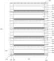
- FIG. 1is a partial perspective view of an exemplary embodiment of an electrode including an array of spaced apart segments.
- FIG. 2is another perspective view of the exemplary embodiment of an electrode including the array of spaced apart segments embedded in a structural matrix.
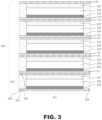
- FIG. 3is a partial side view of an exemplary embodiment of a bipolar stacked battery including bilaminar current collectors and segments embedded in structural matrices.
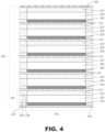
- FIG. 4is a partial side view of another exemplary embodiment of a bipolar stacked battery including segments embedded in structural matrices.
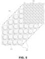
- FIG. 5is a partial exploded view of another exemplary embodiment of a bipolar stacked battery similar to the embodiment of FIG. 4 .
- FIG. 6is a partial cutaway view of an exemplary embodiment of stacked electrodes similar those in the embodiment of FIG. 4 .
- FIG. 7is a side view of various example unit cell configurations.
- FIG. 8is a partial side view of an example unit cell dispensing system.
- FIG. 9is a side view of an example bipolar stacked battery made from unit cells similar to that shown in FIG. 7 .
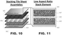
- FIG. 10is an exploded view of an example unit cell similar to that shown in FIG. 7 .
- FIG. 11is a partial detailed view of the example unit cell shown in FIG. 10 .
- FIG. 12is a partial side view of various example materials which may be used in a unit cell.
- the present inventionprovides new cell architectures and methods for their fabrication suitable for use in solid state batteries that will enable the batteries to be flexible and capable of assuming a rolled or folded stack structure.
- Active materialmeans the material in a battery layer which is participating in the electrochemical reaction. This may include a material transporting or storing Li atoms but exclude materials such as additives to increase the electronic conductivity. Formation, as used throughout this specification, means the process or state where all the materials in the cell become active and the device may behave as a battery. For example, formation may be bonding all three layers (anode, electrolyte, and cathode) together so that the electrochemical reaction can occur.
- liquid based batteriesare fabricated in two steps.
- layers of each electrode typeare cast from a slurry onto a metal foil, or current collector.
- the cast slurries on the metal current collectorscan be several meters long, and the process is amenable to continuous roll-to-roll processing.
- the dried electrodes from the slurriesare composites which contain flexible polymer binders in addition to the active materials.
- a stackis then formed comprised of three components: the anode, separator, and cathode. This stack can be rolled, or folded, and placed inside a container. Once in the container, the liquid electrolyte is added and the battery is formed.
- the combination of discrete layers in a rolled or folded geometryis called the cell architecture.
- the cell architecture described aboveis advantageous from a manufacturing stand point since the process is amenable to roll-to-roll continuous processing and is therefore inexpensive.
- new battery technologiesincluding solid state batteries, must be amenable to continuous processing to some extent in order to be cost competitive with the incumbent technology.
- This continuous processing of solid state batteriesmay include casting each of the three layers—anode, electrolyte, and cathode—from a slurry.
- a high temperature sintering stepis required to form the solid state battery. At such high temperatures, any polymer, which may provide flexibility to the film, may be lost. As such, the resulting films have limited flexibility and cannot be rolled as a continuous sheet.
- the new cell architectures disclosed hereinmay minimize the fracture of the layers and may enable an inherently brittle material to be used in a roll-to-roll continuous process.
- a cell architectureis a culmination of how the battery pieces—anode, electrolyte, and cathode—are assembled into a package. For example, the rolling or folding of discrete composite layers of a battery constitute different package assemblies. Several different techniques, such as film deposition, may be utilized in order to form the disclosed cell architectures.
- the layer materialmay be broken up into regularly repeating sub-units, similar to tiles or segments 11 ,
- the repeating pattern of segments 11may form an array 15 .
- These segments 11may offer advantages such as reducing the aspect ratio—each segment 11 has a small area compared to its thickness—so that fracture is less likely.
- Another benefit of the segments 11is the flexibility they may allow for in the resulting structures, such as segments 11 dispersed on a flexible current collector 13 .
- the flexible structures or arrays 15may be used in roll-to-roll processing.
- the spaces 17 between the tiles, or segments 11may be back filled with a second material (such as a polymer or other flexible material). As seen in FIG. 2 , this second material filling in the spaces 17 between the segments 11 forms a structural matrix 19 .
- the structural matrix 19may provide structural support for the segments 11 .
- the structural matrix materialmay or may not be electrochemically active.
- the segments 11 embedded in the structural matrix 19may form a “tiled” structure with polymeric “grout” which may be a composite.
- this novel cell architectureoffers distinct advantages for solid state batteries.
- the segments 11may be of any size.
- the segments 11may be as small as 1-5 micrometers or as large 1-5 centimeters across.
- the segments 11may have a thickness of 1-5 micrometers up to a thickness of 100 micrometers.
- the segments 11may be of any shape.
- the segments 11may be formed in the shape of polyhedrons, or other self-similar shapes, which may be closely packed. These close-packed structures may advantageously minimize the space 17 between each segment 11 , thus saving on the space that the entire array 15 would otherwise occupy.
- the segments 11may be shaped as hexagons, squares, triangles, discs (as seen in FIGS. 5 - 6 ), or any combination thereof.
- the segments 11may be randomly formed or fractured into various shapes which may lower processing costs.
- a three-layer continuous sheet of an anode, solid-state electrolyte, and cathodemay be cast, sintered, and then fractured to form the array 15 .
- the randomly occurring fractures, or spaces 17 , along the three-layer continuous sheetmay be filled with a flexible material, for example by spraying or pouring the flexible material in a liquid state over the sheet and allowing it to set to form the structural matrix 19 .
- the segments 11may be spaced any distance away from each other.
- the segments 11may be spaced anywhere from 100-900 nanometers, 1-9 micrometers, or 10-50 micrometers away from each other.
- the segments 11may be of any composition.
- the composition of a segment 11may be different in the as-deposited state as compared to the as-formed state.
- the composition in the as-deposited statemay contain additives, besides the active material, to enhance deposition.
- the composition in the as-deposited statemay contain additives to enhance the battery performance after formation.
- the structural matrix 19may be of any composition.
- the structural matrix 19may be advantageously formed of a flexible polymer-based material which may enhance the mechanical properties of the sheet.
- the structural matrix 19may be formed of any material, such as thermoplastic polymers, inorganic polymers, metals, glass, or ceramics.
- Non-limiting example polymeric materialsinclude polyolefins (e.g., polypropylene or polyethylene), polystyrene, divinylbenzene, and styrene-divinylbenzene copolymer.
- segments 111may be formed from layers of cathode 123 , solid electrolyte 125 , and anode 127 .
- the layersmay be sintered together in continuous sheets and divided into the segments 111 , and then dispersed into an array (not shown) over a first current collector 113 ,
- the spaces between the segments 111may be filled with a structural matrix 119 .
- the structural matrix 119may be made of a polymer or other flexible material. Alternatively, the structural matrix 119 may be of any other material.
- a second current collector 131may be applied over the top of the array of tri-layered segments 111 in a structural matrix.
- the first and second current collectors 113 , 131may be made of flexible material or thin foils with some flexibility.
- the first current collector 113may comprise a conductive aluminum foil
- the second current collector 131may be conductive fabric with metallic threading or a mesh.
- the layers of a first current collector 113 , cathode 123 , solid electrolyte 125 , anode 127 , and second current collector 131may form a unit cell 121 .
- Multiple layers of unit cells 121may be rolled or stacked or otherwise arranged to form a battery.
- the unit cells 121may be stacked in series to form a bipolar stacked battery 129 with bilaminar current collectors (formed of the second and first current collectors 131 , 113 ) between each anode 127 and cathode 123 in adjacent half cells, Stacking the unit cells 121 in series provide higher voltages in the bipolar batteries 129 . Varying numbers of stacked unit cells 121 may provide a modular battery system to advantageously meet changing needs.
- a layer of a unit cell 121 comprising the array of segments 111may be stored in a roll and dispensed, cut, and stacked as needed.
- the unit cells 121may be stacked with an insulator between the first current collectors 113 and the second current collectors 131 creating a monopolar alternative to the bipolar arrangement.
- a parallel connection of the first current collectors 113 and a parallel connection of the second current collectors 131provides for higher cell capacity in the battery.
- unit cells 221may be further stacked or rolled or otherwise arranged to form an electrochemical device 229 .
- the current collector 213 of the electrode, next to the anode 223may act as a conductor for the cathode 227 of the adjacent unit cell 221 .
- a final current collector 231may be placed atop or otherwise connected to the stack of unit cells 221 to form a bipolar battery.
- FIG. 5shows an exploded view of how unit cells 221 comprising arrays of segments 211 (similar to those shown in FIG. 4 ) may be stacked and topped with current collector 231 to form a bipolar battery 229 .
- FIG. 6shows a stack of two unit cell 221 arrays with a quarter of the top layer shown in dashed lines to illustrate one possible arrangement of the segments 211 of each unit cell 221 directly on top of one another.
- the unit cells 221may be arranged so that the segments 211 of adjacent unit cells 221 are offset from each other.
- Particular arrangements of the segments 211 within the stacks 229may aid in structural stability of the stack 229 or even the flexibility of the same.
- FIGS. 5 - 6are shown without the structural matrix 219 , but the segments 211 may be embedded in a structural matrix material at each unit cell 221 layer in the bipolar battery stack 229 .
- a unit cell 521may be formed from layers of polymer composite anode 523 , solid electrolyte 525 , and polymer composite cathode 527 . Either or both of the current collectors 513 , 531 may be applied to the top and/or bottom of the unit cell 521 .
- the layers of polymer composite anode 523 , solid electrolyte 525 , and polymer composite cathode 527may be arranged in an array of segments 511 within a structural matrix 519 , which may comprise a polymer material.
- the structural matrix 519may provide support for the segments 511 with the current collectors 513 , 531 applied separately.
- the polymer composite anode 523may comprise anode active material mixed with a polymer.
- the polymer composite cathode 527may comprise cathode active material mixed with a polymer.
- the solid electrolyte 525may comprise lithium lanthanum zirconium oxide or any other solid electrolyte material.
- the solid electrolyte 625may comprise any solid electrolyte material, such as lithium lanthanum zirconium oxide, for example.
- the ceramic composite anode 623may comprise anode active material mixed with a ceramic to form a composite.
- the ceramic composite cathode 627may comprise cathode active material mixed with a ceramic to form a composite.
- a unit cell 721may be formed from layers of current collector 713 , lithium metal anode 735 , solid electrolyte 725 , ceramic composite cathode 727 , and current collector 731 .
- the segments 711are supported by the current collector 713 , which may be metal foil, but as described above a structural matrix may also support the segments 711 in an array.
- Lithium metalmay replace either of the electrodes in a unit cell.
- FIG. 7shows the anode comprising, lithium metal 735 .
- FIG. 8shows an example rolled dispensing system for sheets of a unit cell 521 similar to that shown in FIG. 7 .
- the sheets of the unit cell 521may comprise an array of segments 511 supported by a structural matrix 519 .
- the sheetsmay be rolled around a cylindrical dispenser or drum 550 for easy accessibility. The length and width of a particular cell stack may be cut from the sheet after it is drawn from the drum 550 .
- the drum 550may be arranged with other drums supplying sheets of other unit cells and/or current collectors such as metal foils. This arrangement could supply a system for continuous roll manufacturing of batteries. This may be advantageous for quickly manufacturing mass quantities of stacked, folded, or rolled batteries while utilizing electrodeposition sprays of components or other techniques amenable to continuous roll or sheet manufacturing.
- the rolled unit cells 521 arranged around a drum 550may also be advantageous for custom battery sizes where the length and width may be cut or folded from the larger array of segments 511 in the sheet.
- a bipolar stacked battery 629may be formed from layers of unit cells similar to that shown in FIG. 7 .
- the current collector 613provides support for the segments 611 in their array.
- the current collector 613may act as the conductor for both the anode of one unit cell 621 and the cathode of an adjacent unit cell.
- the current collector 631may top off the battery stack and provide a good conductor for one terminal of the bipolar stacked battery 629 .
- a unit cell 621 similar to one embodiment shown in FIG. 7may be formed from stacking segments 611 of an electrolyte layer 625 between electrode layers in an array.
- the unit cell array 621may be placed between current collectors 613 , 631 .
- the electrode layersmay comprise a layer of ceramic composite anode material 623 and a layer of ceramic composite cathode material 627 .
- the electrode layersmay comprise any suitable anode or cathode material such as those seen in FIG. 12 , for example, discrete cathode material 627 A, polymer composite cathode material 527 , discrete anode material 623 A, polymer composite anode material 523 , and lithium metal 735 .
- Methods for forming electrodes or solid state electrolytes of the inventionmay include the steps of: (a) forming an array comprising spaced apart segments; and (b) depositing a flexible material between the segments.
- the array comprising spaced apart segmentsmay be formed by casting a slurry on a surface to form the array comprising spaced apart segments, and sintering the segments.
- Non-limiting example slurry formulations for forming the segmentsmay include; (i) one or more active battery materials (e.g., lithium lanthanum zirconium oxide as a component of a solid electrolyte, or lithium host materials for the anode or cathode of a lithium ion battery); (ii) one or more binders; (iii) one or more dispersants (used to prevent suspended powders such as the active battery materials from settling); (iv) one or more plasticizers (for increasing the workability of the cast segments); (v) one or more sintering aids (i.e., a material added to the system that melts before other components in liquid phase sintering to cause grains to rearrange into a more favorable packing arrangement and provide attraction between the grains through capillary action; and (vi) one or more solvents.
- the slurry componentsare mixed and a layer is cast which is then sintered forming a ceramic layer suitable for use in a solid state battery.
- the slurry formulation used in forming the segmentscan be tailored for solid state batteries by addressing the problem of lithium volatility in the slurry during sintering, A change in the material formulation from the loss of lithium can lead to negative consequences for battery performance (especially when using LLZO as the electrolyte).
- excess lithiumis added to the system to account for lithium loss, Lithium boron oxide may be used as the sintering aid; however, instead of directly adding lithium boron oxide, a precursor (e.g., a source of borate ions such as a boron containing alkoxide including tri-isopropyl borate) can be added and the precursor forms lithium boron oxide from the excess lithium.
- the slurry componentsare mixed until uniform and then a continuous layer or layer of segments is cast.
- the thickness of the cast layercan be controlled, and layers 10-150 microns in thickness are suitable for a solid electrolyte or an anode or a cathode of a solid state battery.
- Subsequent layerscan be cast on top of one another.
- the anodecan be cast first, followed by the electrolyte, and finally the cathode.
- the cathodecan be cast first, followed by the electrolyte, and finally the anode.
- Slurry formulations used in forming the segments 11can be utilized in a low temperature co-fired ceramics process. Additional constraints, not present in related fields, must be considered with electrochemical applications such as a solid state battery. Primarily, many solid state battery materials contain a large fraction of the element lithium, which is volatile at the high temperatures required for sintering. The loss of lithium, and thus change in the battery material formulation, will have negative consequences for the performance of the battery. This is especially true for solid electrolytes such as LLZO. Thus, any means of achieving a dense layer (i.e., sintering) at a lower temperature will help to alleviate the lithium loss problem.
- the slurry formulation described hereinhas been tailored to, among other things, specifically address lithium loss during sintering.
- each component of example slurry formulations used in forming the segments 11i.e., active battery material, sintering aid, dispersant, plasticizer, binder, and solvent.
- the active battery materialsmay be: (i) a component of a solid electrolyte, or (ii) lithium host materials for the anode or cathode of a lithium ion battery.
- the active battery materialsmay be particles.
- the suitable particlesmay have an average diameter of 1 nanometer to 500 micrometers.
- the particlesmay have any suitable shapes, including spherical. In another embodiment, the suitable particles may have more than one shape.
- the active battery materialsmay be fibers.
- a suitable solid electrolyte active materialis Li-ion fast conducting materials.
- the solid electrolytecan be any combination oxide or phosphate materials with the garnet, perovskite, NaSICON, or LiSICON phase.
- the garnet phasecan have the formula Li u Re v M w A x O y , wherein Re can be any combination of elements with a nominal valance of +3 including La, Nd, Pr, Pm, Sm, Sc, Eu, Gd, Tb, Dy, Y, Ho, Er, Tm, Yb, and Lu; M can be any combination of metals with a nominal valance of +3, +4, +5 or +6 including Zr, Ta, Nb, Sb, W, Hf, Sn, Ti, V, Bi, Ge, and Si; A can be any combination of dopant atoms with nominal valance of +1, +2, +3 or +4 including H, Na, K, Rb, Cs, Ba, Sr, Ca, Mg, Fe
- the garnetcan be lithium lanthanum zirconium oxide having the formula Li 6.25 La 3 Zr 2 Al 0.25 O 12 (LLZO). Disadvantages associated with the degradation of liquid electrolytes can be eliminated if a solid electrolyte is used. To match or exceed the current ionic conductivity values of a liquid electrolyte, solid electrolytes need to be near theoretical density and be thermally and chemically stable in air and against metallic lithium. The formation of lithium dendrites in the solid electrolyte after charging cycles should be minimized or eliminated. High-density solid electrolytes can be produced through optimization of the slurry sintering conditions, i.e., time, temperature, pressure, atmosphere and chemical composition.
- Ceramic powder processing optimization of the sintering temperature and sintering mechanismhas been shown here to increase the density as well as the Li-ion conductivity in the garnet lithium lanthanum zirconium oxide electrolyte Li 6.25 La 3 Zr 2 Al 0.25 O 12 (LLZO).
- a suitable cathode active materialis a lithium host material capable of storing and subsequently releasing lithium ions.
- An example cathode active materialis a lithium metal oxide wherein the metal is one or more aluminum, cobalt, iron, manganese, nickel and vanadium.
- Non-limiting example lithium metal oxidesare LiCoO 2 (LCO), LiFeO 2 , LiMnO 2 (LMO), LiMn 2 O 4 , LiNiO 2 (LNO), LiNi x CO y O 2 , LiMn x CO y O 2 , LiMn x Ni y O 2 , LiMn x Ni y O 4 , LiNi x Co y Al z O 2 , LiNi 1/3 Mn 1/3 Co 1/3 O 2 and others.
- LCOLiCoO 2
- LiFeO 2LiMnO 2
- LiMn 2 O 4LiNiO 2 (LNO)
- LiNi x CO y O 2LiMn x CO y O 2
- LiMn x Ni y O 2LiMn x Ni y O 4
- LiNi x Co y Al z O 2LiNi 1/3 Mn 1/3 Co 1/3 O 2 and others.
- cathode active materialsis a lithium-containing phosphate having a general formula LiMPO 4 wherein M is one or more of cobalt, iron, manganese, and nickel, such as lithium iron phosphate (LFP) and lithium iron fluorophosphates.
- Mis one or more of cobalt, iron, manganese, and nickel, such as lithium iron phosphate (LFP) and lithium iron fluorophosphates.
- LFPlithium iron phosphate
- Many different elementse.g., Co, Mn, Ni, Cr, Al, or Li, may be substituted or additionally added into the structure to influence electronic conductivity, ordering of the layer, stability on dilithiation and cycling performance of the cathode materials.
- the cathode active materialcan be a mixture of any number of these cathode active materials.
- a suitable anode active materialis a lithium host material capable of incorporating and subsequently releasing the lithium ion such as graphite, lithium metal, lithium titanium oxide, hard carbon, a tin/cobalt alloy, or silicon/carbon.
- the anode active materialcan be a mixture of any number of these anode active materials.
- Sintering AidOptional sintering aids which melt and form a liquid can assist in sintering, of a cast slurry formulation used in forming the segments 11 via liquid phase sintering.
- the sintering aidprovides a source of borate ions.
- the sintering aidprovides a source of phosphate ions.
- the sintering aidprovides a source of silicate ions.
- the sintering aidprovides a source of aluminate ions.
- Example sintering aidscan be selected from boric acid, boric acid salts, boric acid esters, boron alkoxides phosphoric acid, phosphoric acid salts, phosphate acid esters, silicic acid, silicic acid salts, silanols, silicon alkoxides, aluminum alkoxides and mixtures thereof that assist in the formation of lithium boron oxide (LBO), lithium phosphate, lithium silicate, and lithium aluminum oxide phases.
- LBOlithium boron oxide
- excess lithiumreacts with the sintering aid to form a lithium borate phase in-situ between the LLZO grains during heating.
- a liquid source of the sintering aide.g., tri-isopropyl borate as a source of borate ions
- the source of borate ionsis a liquid, it uniformly and conformally coats the active battery materials in the slurry thereby forming interphase layers upon sintering.
- excess lithiumis added to the system to account for the lithium loss that occurs during high temperature processing. The excess lithium acts as a source to form the LBO phase from the source of borate ions (e.g., tri-isopropyl borate).
- An LLZO having an excess of lithium ionscan provide the lithium ions needed to react with the source of borate ions to form the LBO phase.
- the slurry formulationmay optionally include a dispersant.
- a dispersantOne purpose of the dispersant is to stabilize the slurry and prevent the suspended active battery material particles from settling out.
- the dispersantcan also provide a source of lithium ions that is needed to react with the sintering aid.
- the dispersant chosenmay contain lithium ions and is soluble in the solvent. This means that the dispersant can stabilize the particles in the slurry during casting and also act as a source of lithium ions when the temperature is increased after the cast segments are dried.
- the dispersantmay be selected from the group consisting of salts of lithium and a fatty acid.
- the fatty acidmay be selected from lauric acid, myristic acid, palmitic acid, stearic acid, oleic acid, linoleic acid, linolenic acid, arachidic acid, and behenic acid.
- the dispersantis lithium stearate.
- the slurry formulationmay optionally include a plasticizer.
- the purpose of the plasticizeris to increase the workability of the as-cast segments.
- the plasticizeris a naturally derived plant based oil.
- the plasticizermay be selected from the group consisting of coconut oil, castor oil, soybean oil, palm kernel oil, almond oil, corn oil, canola oil, rapeseed oil, and mixtures thereof.
- a petroleum derivativecould also be used for the plasticizer, the choice of a plant oil is sustainable.
- the plasticizerwas also chosen to reduce the evaporation rate of the solvent and increase the mechanical ductility of the slurry after drying.
- coconut oilis used for the plasticizer.
- the slurry formulationmay optionally include a binder.
- the binderinclude: poly(methylmethacrylate), poly(vinylacetate), polyvinyl alcohol, polyethyleneoxide, polyvinylpyrrolidone, polyvinyl ether, polyvinylchloride, polyacrylonitrile, polyvinylpyridine, styrene-butadiene rubber, acrylonitrile-butadiene rubber, polyethylene, polypropylene, ethylene-propylene-diene terpolymers (EPDM), cellulose, carboxymethylcellulose, starch, hydroxypropylcellulose, and mixtures thereof.
- the binderis preferably a non-fluorinated polymeric material.
- Fluorinated polymerssuch as polytetrafluoroethylene (Teflon®) and polyvinylidene fluoride, are often used as binders in current Li-ion batteries.
- Teflon®polytetrafluoroethylene
- polyvinylidene fluorideare often used as binders in current Li-ion batteries.
- the cast ceramic segment layers of the present inventionwill be sintered.
- the elevated temperatures and the presence of fluorine in the polymersresults in the unavoidable formation of the compound LiF and deterioration of the performance of the battery.
- an acrylic polymer, poly(methylmethacrylate)can be chosen since these polymers leave behind little to no residue when heated.
- SolventA solvent is useful in a slurry formulation to dissolve the binder and act as a medium for mixing the other additives. Any suitable solvents may be used for mixing the active battery material particles, dispersant, and binder into a uniform slurry. Suitable solvents may include alkanols (e.g., ethanol), nitriles (e.g., acetonitrile), alkyl carbonates, alkylene carbonates (e.g., propylene carbonate), alkyl acetates, sulfoxides, glycol ethers, ethers, N-methyl-2-pyrrolidone, dimethylformamide, dimethylacetamide, tetrahydrofuran, or a mixture of any of these solvents.
- alkanolse.g., ethanol
- nitrilese.g., acetonitrile
- alkyl carbonatese.g., alkylene carbonates (e.g., propylene carbonate)
- a mixture of two solventscan be chosen.
- a solventcan be chosen to dissolve the binder and the dispersant.
- a second solventcan be added and the ratio of plasticizer varied to tune the evaporation rate and resulting cast slurry segments.
- a mixture of ethanol and acetonitrilecan be used for the solvent.
- the slurry formulationmay include other additives.
- the cathode or anode active battery material particlesmay be mixed with other particles, such as conductive particles.
- Any conductive materialmay be used without particular limitation so long as it has suitable conductivity without causing chemical changes in the fabricated battery, Examples of conductive materials include graphite; carbon blacks such as carbon black, acetylene black, Ketjen channel black, furnace black, lamp black and thermal black; conductive fibers such as carbon fibers and metallic fibers; metallic powders such as aluminum powder and nickel powder; conductive whiskers such as zinc oxide and potassium titanate; conductive metal oxides such as titanium oxide; and polyphenylene derivatives.
- Any suitable methodmay be used to mix the active battery material particles and/or other particles with the sintering aid, plasticizer, binder and solvent into a uniform slurry.
- Suitable mixing methodsmay include sonication, mechanical stirring, physical shaking, vortexing, ball milling, and any other suitable means.
- the formulationis cast on a substrate surface to form a cast layer or a cast layer of segments.
- the substratemay include any stable and conductive metals suitable as a current collector for the battery.
- a suitable metallic substratemay include aluminum, copper, silver, iron, gold, nickel, cobalt, titanium, molybdenum, steel, zirconium, tantalum, and stainless steel.
- the metal substrateis aluminum.
- the slurry layer cast on the surfacemay have a thickness in the range of a few micrometers to a few centimeters. In one embodiment, the thickness of the cast slurry layer is in the range of 10 micrometers to 150 micrometers, preferably 10 micrometers to 100 micrometers, more preferably 10 micrometers to 50 micrometers.
- the green layer or green layer of segmentscan be dried and sintered at a temperature in a range of 300° C. to 1200° C., more preferably 600° C. to 1000° C. to achieve the necessary electrochemical properties.
- multiple layerscan be cast on top of one another.
- the anodecan be cast first on the metal substrate, followed by casting the electrolyte on the anode, and finally casting the cathode on the electrolyte.
- the cathodecan be cast first on the metal substrate, followed by the electrolyte, and finally the anode.
- the multi-layer green cast layer or green cast layer of segmentscan be dried and sintered at a temperature in a range of 300° C. to 1200° C., more preferably 600° C. to 1000° C. to achieve the necessary electrochemical properties.
- Tables 1, 2 and 3 belowprovide general formulas for slurries for casting a cast a layer or a layer of segments according to the present invention.
- the present inventionprovides methods and structures for the fabrication of solid-state batteries, such as lithium ion solid state batteries, into segmented cell architectures.
Landscapes
- Chemical & Material Sciences (AREA)
- Engineering & Computer Science (AREA)
- Chemical Kinetics & Catalysis (AREA)
- Electrochemistry (AREA)
- General Chemical & Material Sciences (AREA)
- Manufacturing & Machinery (AREA)
- Materials Engineering (AREA)
- Inorganic Chemistry (AREA)
- Condensed Matter Physics & Semiconductors (AREA)
- General Physics & Mathematics (AREA)
- Physics & Mathematics (AREA)
- Crystallography & Structural Chemistry (AREA)
- Dispersion Chemistry (AREA)
- Secondary Cells (AREA)
- Battery Electrode And Active Subsutance (AREA)
- Cell Electrode Carriers And Collectors (AREA)
Abstract
Description
| TABLE 1 |
| Slurry for Casting Solid State Electrolyte |
| Layer Or Layer Of Segments |
| Component Functional Description | Weight Percentage | ||
| Lithium Ion Conductor | 35-65 | wt % | ||
| Binder | 1-5 | wt % | ||
| Dispersant - Source of Lithium Ions | 0.1-5 | wt % | ||
| Plasticizer | 1-30 | wt % | ||
| Sintering Aid - Source of Borate Ions | 0-5 | wt % | ||
| Solvent | 10-55 | wt % | ||
| All weight percentages are percent by weight of the total slurry. | ||||
| TABLE 2 |
| Slurry for Casting Cathode Layer Or Layer Of Segments |
| Component Functional Description | Weight Percentage | ||
| Lithium Host Material | 35-65 | wt % | ||
| Binder | 1-5 | wt % | ||
| Dispersant - Source of Lithium Ions | 0.1-5 | wt % | ||
| Plasticizer | 1-30 | wt % | ||
| Sintering Aid - Source of Borate Ions | 0-5 | wt % | ||
| Solvent | 10-55 | wt % | ||
| All weight percentages are percent by weight of the total slurry. | ||||
| TABLE 3 |
| Slurry for Casting Anode Layer Or Layer Of Segments |
| Component Functional Description | Weight Percentage | ||
| Lithium Host Material | 35-65 | wt % | ||
| Binder | 1-5 | wt % | ||
| Dispersant - Source of Lithium Ions | 0.1-5 | wt % | ||
| Plasticizer | 1-30 | wt % | ||
| Sintering Aid - Source of Borate Ions | 0-5 | wt % | ||
| Solvent | 10-55 | wt % | ||
| All weight percentages are percent by weight of the total slurry. | ||||
Claims (22)
Priority Applications (1)
| Application Number | Priority Date | Filing Date | Title |
|---|---|---|---|
| US15/421,499US12308391B2 (en) | 2016-02-01 | 2017-02-01 | Segmented cell architecture for solid state batteries |
Applications Claiming Priority (2)
| Application Number | Priority Date | Filing Date | Title |
|---|---|---|---|
| US201662289559P | 2016-02-01 | 2016-02-01 | |
| US15/421,499US12308391B2 (en) | 2016-02-01 | 2017-02-01 | Segmented cell architecture for solid state batteries |
Publications (2)
| Publication Number | Publication Date |
|---|---|
| US20170222254A1 US20170222254A1 (en) | 2017-08-03 |
| US12308391B2true US12308391B2 (en) | 2025-05-20 |
Family
ID=59387146
Family Applications (1)
| Application Number | Title | Priority Date | Filing Date |
|---|---|---|---|
| US15/421,499ActiveUS12308391B2 (en) | 2016-02-01 | 2017-02-01 | Segmented cell architecture for solid state batteries |
Country Status (6)
| Country | Link |
|---|---|
| US (1) | US12308391B2 (en) |
| EP (1) | EP3411917A4 (en) |
| JP (2) | JP2019507473A (en) |
| KR (1) | KR102841002B1 (en) |
| CN (2) | CN117895056A (en) |
| WO (1) | WO2017136320A1 (en) |
Families Citing this family (22)
| Publication number | Priority date | Publication date | Assignee | Title |
|---|---|---|---|---|
| EP3252024B1 (en) | 2016-05-27 | 2019-12-18 | Toyota Jidosha Kabushiki Kaisha | Oxide electrolyte sintered body and method for producing the same |
| JP2019046721A (en)* | 2017-09-05 | 2019-03-22 | トヨタ自動車株式会社 | Slurry, method for manufacturing solid electrolyte layer, and method for manufacturing all-solid battery |
| JP6962094B2 (en) | 2017-09-21 | 2021-11-05 | トヨタ自動車株式会社 | Method for producing garnet-type ionic conductive oxide and oxide electrolyte sintered body |
| US10505162B2 (en) | 2017-10-05 | 2019-12-10 | Analog Devices, Inc. | Battery housing |
| WO2019079258A2 (en)* | 2017-10-16 | 2019-04-25 | The Regents Of The University Of Colorado, A Body Corporate | Anode material - method of production and solid-state battery made therewith |
| EP3713000A4 (en)* | 2017-11-13 | 2021-10-20 | Murata Manufacturing Co., Ltd. | SOLID STATE BATTERY |
| JP6954032B2 (en)* | 2017-11-15 | 2021-10-27 | トヨタ自動車株式会社 | Electrodes for non-aqueous electrolyte secondary batteries |
| JP6988473B2 (en) | 2017-12-28 | 2022-01-05 | トヨタ自動車株式会社 | Battery separators, lithium batteries, and methods for manufacturing these. |
| US11764392B2 (en) | 2018-03-01 | 2023-09-19 | Analog Devices, Inc. | Battery assembly and method of manufacturing the same |
| WO2020014268A1 (en) | 2018-07-09 | 2020-01-16 | 24M Technologies, Inc. | Continuous and semi-continuous methods of semi-solid electrode and battery manufacturing |
| CN109755637B (en)* | 2018-12-29 | 2022-04-19 | 浙江南都电源动力股份有限公司 | Oxide ceramic composite solid electrolyte, preparation method and application thereof |
| CN109888372B (en)* | 2019-02-25 | 2022-06-21 | 蜂巢能源科技有限公司 | Solid Electrolyte Composite Membrane and Its Application |
| JP7211165B2 (en)* | 2019-03-01 | 2023-01-24 | トヨタ自動車株式会社 | All-solid-state battery and manufacturing method thereof |
| US11264609B2 (en)* | 2019-06-21 | 2022-03-01 | Hyundai Motor Company | Method of manufacturing cathode composite for all-solid-state battery and method of manufacturing all-solid-state battery comprising same |
| JP2023513009A (en) | 2020-01-31 | 2023-03-30 | ザ リージェンツ オブ ザ ユニバーシティ オブ ミシガン | Rapid Induction Sinter Forging for Roll-to-Roll Continuous Manufacturing of Thin Films |
| KR20210109730A (en)* | 2020-02-27 | 2021-09-07 | 현대자동차주식회사 | Vehicle body member having charger and discharger function |
| EP4226434A1 (en) | 2020-10-09 | 2023-08-16 | 24M Technologies, Inc. | Methods of continuous and semi-continuous production of electrochemical cells |
| CN112803063A (en)* | 2021-03-19 | 2021-05-14 | 国家纳米科学中心 | Flexible lithium ion battery and preparation method and application thereof |
| EP4220747A4 (en)* | 2021-04-15 | 2024-07-24 | LG Energy Solution, Ltd. | ELECTRODE AND METHOD FOR MANUFACTURING THE ELECTRODE |
| WO2024106224A1 (en)* | 2022-11-18 | 2024-05-23 | 株式会社トクヤマ | Material for forming all-solid-state lithium ion secondary battery negative electrode, and all-solid-state lithium ion secondary battery |
| DE102023004490A1 (en)* | 2023-11-08 | 2025-05-08 | Mercedes-Benz Group AG | Layer structure for a solid-state battery and method for producing such a layer structure |
| CN118198480A (en)* | 2024-05-13 | 2024-06-14 | 深圳欣界能源科技有限公司 | Flexible solid electrolyte membrane and preparation method thereof, solid battery and preparation method thereof, and power utilization device |
Citations (56)
| Publication number | Priority date | Publication date | Assignee | Title |
|---|---|---|---|---|
| US1332483A (en) | 1919-05-29 | 1920-03-02 | Bridge Arthur | Sea-water battery for vessels |
| US3033909A (en) | 1959-11-03 | 1962-05-08 | Union Carbide Corp | Fiber-bonded electrodes |
| US3129118A (en) | 1959-05-26 | 1964-04-14 | Servel Inc | Reserve electric battery with combined electrode and separator member |
| US3428495A (en) | 1966-02-23 | 1969-02-18 | Accumulateurs Fixes | Separator arrangements for electrochemical power sources,methods of their manufacture and power sources equipped therewith |
| US4022952A (en) | 1975-12-19 | 1977-05-10 | The United States Of America As Represented By The Secretary Of The Air Force | Electrode assembly for bipolar battery |
| US4192913A (en) | 1978-11-27 | 1980-03-11 | Magnavox Government And Industrial Electronics Company | Deferred action battery having an improved depolarizer |
| US4400447A (en) | 1981-06-03 | 1983-08-23 | The Continental Group, Inc. | Combined current collector and electrode separator |
| US4551399A (en) | 1983-06-02 | 1985-11-05 | Aleksandar Despic | Bipolar battery |
| US4822698A (en) | 1987-05-15 | 1989-04-18 | Westinghouse Electric Corp. | Seawater power cell |
| US5395709A (en) | 1993-10-18 | 1995-03-07 | Westinghouse Electric Corporation | Carbon bipolar walls for batteries and method for producing same |
| US20030013012A1 (en)* | 2000-02-08 | 2003-01-16 | Soon-Ho Ahn | Stacked electrochemical cell |
| US6529308B2 (en) | 1998-07-10 | 2003-03-04 | Saint-Gobain Glass France | Electrochemical device |
| US20030099884A1 (en) | 2001-07-27 | 2003-05-29 | A123Systems, Inc. | Battery structures, self-organizing structures and related methods |
| US20040106037A1 (en) | 2002-11-02 | 2004-06-03 | Samsung Sdi Co., Ltd. | Separator having inorganic protective film and lithium battery using the same |
| US20050214621A1 (en)* | 2004-03-26 | 2005-09-29 | Liu Yung-Yi | Flat panel direct methanol fuel cell and method of making the same |
| US7282295B2 (en) | 2004-02-06 | 2007-10-16 | Polyplus Battery Company | Protected active metal electrode and battery cell structures with non-aqueous interlayer architecture |
| US7288340B2 (en)* | 2003-03-20 | 2007-10-30 | Matsushita Electric Industrial Co., Ltd. | Integrated battery |
| JP2008103260A (en) | 2006-10-20 | 2008-05-01 | Idemitsu Kosan Co Ltd | Solid electrolyte sheet, electrode sheet, and all-solid secondary battery using the same |
| US7396612B2 (en) | 2003-07-29 | 2008-07-08 | Matsushita Electric Industrial Co., Ltd. | Lithium ion secondary battery |
| US20090197183A1 (en) | 2008-01-31 | 2009-08-06 | Ohara Inc. | Solid battery and a method for manufacturing an electrode thereof |
| US20100099020A1 (en) | 2007-03-05 | 2010-04-22 | Koninklijke Philips Electronics N.V. | Electrochemical energy source and electronic device provided with such an electrochemical energy source |
| US20110183183A1 (en) | 2010-01-26 | 2011-07-28 | Grady Steven C | Battery arrays, constructions and method |
| US8048571B2 (en) | 2003-10-14 | 2011-11-01 | Polyplus Battery Company | Active metal / aqueous electrochemical cells and systems |
| US20110281173A1 (en) | 2008-02-13 | 2011-11-17 | Seeo, Inc. | Multiple electrolyte electrochemical cells |
| US8114171B2 (en) | 2002-10-15 | 2012-02-14 | Polyplus Battery Company | In situ formed ionically conductive membranes for protection of active metal anodes and battery cells |
| US8124267B2 (en)* | 2005-09-16 | 2012-02-28 | Bong Sup Kang | Lithium secondary battery having partitioned electrolyte |
| US20120141881A1 (en)* | 2009-08-14 | 2012-06-07 | Seeo, Inc | High energy polymer battery |
| JP2012160371A (en) | 2011-02-01 | 2012-08-23 | Panasonic Corp | Lithium ion secondary battery |
| JP2012169071A (en) | 2011-02-10 | 2012-09-06 | Panasonic Corp | Lithium ion secondary battery |
| JP2013058427A (en) | 2011-09-09 | 2013-03-28 | Dainippon Screen Mfg Co Ltd | Lithium ion secondary battery |
| US8486568B2 (en) | 2011-08-18 | 2013-07-16 | Dainippon Screen Mfg. Co., Ltd. | Preparation process of all-solid battery |
| US20140072697A1 (en) | 2012-09-13 | 2014-03-13 | Dainippon Screen Mfg. Co., Ltd. | Method for manufacturing electrode for battery |
| JP2014060014A (en) | 2012-09-14 | 2014-04-03 | Dainippon Screen Mfg Co Ltd | Method of manufacturing electrode for battery and apparatus of manufacturing electrode for battery |
| US8691429B2 (en) | 2008-10-14 | 2014-04-08 | Samsung Sdi Co., Ltd. | Polymer battery pack and method for manufacturing the same |
| US20140099538A1 (en) | 2012-10-09 | 2014-04-10 | Microsoft Corporation | Solid-State Battery Electrodes |
| US20140186720A1 (en) | 2012-12-29 | 2014-07-03 | Murata Manufacturing Co., Ltd. | Material for solid electrolyte |
| WO2014124049A2 (en) | 2013-02-06 | 2014-08-14 | The Board Of Trustees Of The University Of Illinois | Stretchable electronic systems with containment chambers |
| US20140234726A1 (en) | 2013-02-21 | 2014-08-21 | John F. Christensen | Lithium Battery with Composite Solid Electrolyte |
| JP2014179250A (en) | 2013-03-15 | 2014-09-25 | Dainippon Screen Mfg Co Ltd | Method for manufacturing all-solid battery, and manufacturing equipment |
| US8883357B2 (en) | 2008-08-21 | 2014-11-11 | Ngk Insulators, Ltd. | Ceramic material and process for producing the same |
| US8889300B2 (en) | 2012-02-27 | 2014-11-18 | California Institute Of Technology | Lithium-based high energy density flow batteries |
| US8900743B2 (en) | 2011-10-27 | 2014-12-02 | Sakti3, Inc. | Barrier for thin film lithium batteries made on flexible substrates and related methods |
| US8932771B2 (en) | 2012-05-03 | 2015-01-13 | Polyplus Battery Company | Cathode architectures for alkali metal / oxygen batteries |
| US20150024256A1 (en)* | 2013-07-16 | 2015-01-22 | Ford Global Technologies, Llc | Flexible composite solid polymer electrochemical membrane |
| US20150099188A1 (en)* | 2013-10-07 | 2015-04-09 | Quantumscape Corporation | Garnet materials for li secondary batteries and methods of making and using garnet materials |
| US9034421B2 (en) | 2008-01-08 | 2015-05-19 | Sion Power Corporation | Method of forming electrodes comprising sulfur and porous material comprising carbon |
| US9077041B2 (en) | 2012-02-14 | 2015-07-07 | Sion Power Corporation | Electrode structure for electrochemical cell |
| US9093717B2 (en) | 2011-05-20 | 2015-07-28 | Board Of Trustees Of Michigan State University | Methods of making and using oxide ceramic solids and products and devices related thereto |
| US9166214B2 (en) | 2004-07-15 | 2015-10-20 | General Electric Company | Seal ring and associated method |
| US9172114B2 (en) | 2013-05-15 | 2015-10-27 | Quantumscape Corporation | Solid state catholytes and electrolytes for energy storage devices |
| US9246158B2 (en) | 2012-07-24 | 2016-01-26 | Quantumscape Corporation | Nanostructured materials for electrochemical conversion reactions |
| US9276255B2 (en) | 2009-12-23 | 2016-03-01 | Robert Bosch Gmbh | Lithium cell having an improved cathode structure and production method for it |
| US20160099453A1 (en) | 2014-10-02 | 2016-04-07 | Ford Global Technologies, Llc | Composite Separator with Aligned Particles |
| US20160190640A1 (en)* | 2014-12-02 | 2016-06-30 | Polyplus Battery Company | VITREOUS SOLID ELECTROLYTE SHEETS OF Li ION CONDUCTING SULFUR-BASED GLASS AND ASSOCIATED STRUCTURES, CELLS AND METHODS |
| US9531036B2 (en) | 2013-08-23 | 2016-12-27 | Kabushiki Kaisha Toyota Chuo Kenkyusho | Garnet-type ion conducting oxide, complex, lithium secondary battery, manufacturing method of garnet-type ion conducting oxide and manufacturing method of complex |
| US20170047589A1 (en)* | 2014-04-24 | 2017-02-16 | Daiichi Kigenso Kagaku Kogyo Co., Ltd. | Method for producing garnet-type compound, garnet-type compound, and all-solid lithium secondary cell containing said garnet-type compound |
Family Cites Families (5)
| Publication number | Priority date | Publication date | Assignee | Title |
|---|---|---|---|---|
| US6124267A (en)* | 1991-02-05 | 2000-09-26 | Southpac Trust Internationals, Inc. | O-glycan inhibitors of selectin mediated inflammation derived from PSGL-1 |
| KR100582558B1 (en) | 2004-11-25 | 2006-05-22 | 한국전자통신연구원 | Lithium metal cathode for lithium metal polymer secondary battery with spacer and manufacturing method thereof |
| JP5497538B2 (en) | 2010-06-01 | 2014-05-21 | 日本電信電話株式会社 | Solid type secondary battery |
| WO2013099541A1 (en) | 2011-12-27 | 2013-07-04 | 株式会社村田製作所 | Electricity storage device and method for manufacturing same |
| KR101656406B1 (en)* | 2014-07-21 | 2016-09-12 | 경상대학교산학협력단 | Electrode, battery and method of manufacturing the electrode |
- 2017
- 2017-01-31KRKR1020187025301Apatent/KR102841002B1/enactiveActive
- 2017-01-31EPEP17748001.9Apatent/EP3411917A4/enactivePending
- 2017-01-31CNCN202410057823.1Apatent/CN117895056A/enactivePending
- 2017-01-31WOPCT/US2017/015773patent/WO2017136320A1/ennot_activeCeased
- 2017-01-31JPJP2018540027Apatent/JP2019507473A/enactivePending
- 2017-01-31CNCN201780020708.5Apatent/CN108886125A/enactivePending
- 2017-02-01USUS15/421,499patent/US12308391B2/enactiveActive
- 2022
- 2022-12-02JPJP2022193772Apatent/JP7714516B2/enactiveActive
Patent Citations (65)
| Publication number | Priority date | Publication date | Assignee | Title |
|---|---|---|---|---|
| US1332483A (en) | 1919-05-29 | 1920-03-02 | Bridge Arthur | Sea-water battery for vessels |
| US3129118A (en) | 1959-05-26 | 1964-04-14 | Servel Inc | Reserve electric battery with combined electrode and separator member |
| US3033909A (en) | 1959-11-03 | 1962-05-08 | Union Carbide Corp | Fiber-bonded electrodes |
| US3428495A (en) | 1966-02-23 | 1969-02-18 | Accumulateurs Fixes | Separator arrangements for electrochemical power sources,methods of their manufacture and power sources equipped therewith |
| US4022952A (en) | 1975-12-19 | 1977-05-10 | The United States Of America As Represented By The Secretary Of The Air Force | Electrode assembly for bipolar battery |
| US4192913A (en) | 1978-11-27 | 1980-03-11 | Magnavox Government And Industrial Electronics Company | Deferred action battery having an improved depolarizer |
| US4400447A (en) | 1981-06-03 | 1983-08-23 | The Continental Group, Inc. | Combined current collector and electrode separator |
| US4551399A (en) | 1983-06-02 | 1985-11-05 | Aleksandar Despic | Bipolar battery |
| US4822698A (en) | 1987-05-15 | 1989-04-18 | Westinghouse Electric Corp. | Seawater power cell |
| US5395709A (en) | 1993-10-18 | 1995-03-07 | Westinghouse Electric Corporation | Carbon bipolar walls for batteries and method for producing same |
| US6529308B2 (en) | 1998-07-10 | 2003-03-04 | Saint-Gobain Glass France | Electrochemical device |
| US20030013012A1 (en)* | 2000-02-08 | 2003-01-16 | Soon-Ho Ahn | Stacked electrochemical cell |
| US20030099884A1 (en) | 2001-07-27 | 2003-05-29 | A123Systems, Inc. | Battery structures, self-organizing structures and related methods |
| US8114171B2 (en) | 2002-10-15 | 2012-02-14 | Polyplus Battery Company | In situ formed ionically conductive membranes for protection of active metal anodes and battery cells |
| US20040106037A1 (en) | 2002-11-02 | 2004-06-03 | Samsung Sdi Co., Ltd. | Separator having inorganic protective film and lithium battery using the same |
| US7288340B2 (en)* | 2003-03-20 | 2007-10-30 | Matsushita Electric Industrial Co., Ltd. | Integrated battery |
| US7754377B2 (en) | 2003-07-29 | 2010-07-13 | Panasonic Corporation | Lithium ion secondary battery |
| US7758998B2 (en) | 2003-07-29 | 2010-07-20 | Panasonic Corporation | Lithium ion secondary battery |
| US7396612B2 (en) | 2003-07-29 | 2008-07-08 | Matsushita Electric Industrial Co., Ltd. | Lithium ion secondary battery |
| US7931983B2 (en) | 2003-07-29 | 2011-04-26 | Panasonic Corporation | Lithium ion secondary battery |
| US8048571B2 (en) | 2003-10-14 | 2011-11-01 | Polyplus Battery Company | Active metal / aqueous electrochemical cells and systems |
| US8202649B2 (en) | 2003-10-14 | 2012-06-19 | Polyplus Battery Company | Active metal/aqueous electrochemical cells and systems |
| US7829212B2 (en) | 2004-02-06 | 2010-11-09 | Polyplus Battery Company | Protected active metal electrode and battery cell structures with non-aqueous interlayer architecture |
| US8293398B2 (en) | 2004-02-06 | 2012-10-23 | Polyplus Battery Company | Protected active metal electrode and battery cell with ionically conductive protective architecture |
| US8501339B2 (en) | 2004-02-06 | 2013-08-06 | Polyplus Battery Company | Protected lithium electrodes having a polymer electrolyte interlayer and battery cells thereof |
| US7282295B2 (en) | 2004-02-06 | 2007-10-16 | Polyplus Battery Company | Protected active metal electrode and battery cell structures with non-aqueous interlayer architecture |
| US20050214621A1 (en)* | 2004-03-26 | 2005-09-29 | Liu Yung-Yi | Flat panel direct methanol fuel cell and method of making the same |
| US9166214B2 (en) | 2004-07-15 | 2015-10-20 | General Electric Company | Seal ring and associated method |
| US8124267B2 (en)* | 2005-09-16 | 2012-02-28 | Bong Sup Kang | Lithium secondary battery having partitioned electrolyte |
| JP2008103260A (en) | 2006-10-20 | 2008-05-01 | Idemitsu Kosan Co Ltd | Solid electrolyte sheet, electrode sheet, and all-solid secondary battery using the same |
| US20100099020A1 (en) | 2007-03-05 | 2010-04-22 | Koninklijke Philips Electronics N.V. | Electrochemical energy source and electronic device provided with such an electrochemical energy source |
| US9034421B2 (en) | 2008-01-08 | 2015-05-19 | Sion Power Corporation | Method of forming electrodes comprising sulfur and porous material comprising carbon |
| US20090197183A1 (en) | 2008-01-31 | 2009-08-06 | Ohara Inc. | Solid battery and a method for manufacturing an electrode thereof |
| US20110281173A1 (en) | 2008-02-13 | 2011-11-17 | Seeo, Inc. | Multiple electrolyte electrochemical cells |
| US20140377665A1 (en) | 2008-08-21 | 2014-12-25 | Ngk Insulators, Ltd. | Ceramic material and process for producing the same |
| US8883357B2 (en) | 2008-08-21 | 2014-11-11 | Ngk Insulators, Ltd. | Ceramic material and process for producing the same |
| US8691429B2 (en) | 2008-10-14 | 2014-04-08 | Samsung Sdi Co., Ltd. | Polymer battery pack and method for manufacturing the same |
| US20120141881A1 (en)* | 2009-08-14 | 2012-06-07 | Seeo, Inc | High energy polymer battery |
| US9276255B2 (en) | 2009-12-23 | 2016-03-01 | Robert Bosch Gmbh | Lithium cell having an improved cathode structure and production method for it |
| US20110183183A1 (en) | 2010-01-26 | 2011-07-28 | Grady Steven C | Battery arrays, constructions and method |
| JP2012160371A (en) | 2011-02-01 | 2012-08-23 | Panasonic Corp | Lithium ion secondary battery |
| JP2012169071A (en) | 2011-02-10 | 2012-09-06 | Panasonic Corp | Lithium ion secondary battery |
| US9093717B2 (en) | 2011-05-20 | 2015-07-28 | Board Of Trustees Of Michigan State University | Methods of making and using oxide ceramic solids and products and devices related thereto |
| US8486568B2 (en) | 2011-08-18 | 2013-07-16 | Dainippon Screen Mfg. Co., Ltd. | Preparation process of all-solid battery |
| JP2013058427A (en) | 2011-09-09 | 2013-03-28 | Dainippon Screen Mfg Co Ltd | Lithium ion secondary battery |
| US8900743B2 (en) | 2011-10-27 | 2014-12-02 | Sakti3, Inc. | Barrier for thin film lithium batteries made on flexible substrates and related methods |
| US9077041B2 (en) | 2012-02-14 | 2015-07-07 | Sion Power Corporation | Electrode structure for electrochemical cell |
| US8889300B2 (en) | 2012-02-27 | 2014-11-18 | California Institute Of Technology | Lithium-based high energy density flow batteries |
| US8932771B2 (en) | 2012-05-03 | 2015-01-13 | Polyplus Battery Company | Cathode architectures for alkali metal / oxygen batteries |
| US9246158B2 (en) | 2012-07-24 | 2016-01-26 | Quantumscape Corporation | Nanostructured materials for electrochemical conversion reactions |
| JP2014056747A (en) | 2012-09-13 | 2014-03-27 | Dainippon Screen Mfg Co Ltd | Process of manufacturing electrode for cell |
| US20140072697A1 (en) | 2012-09-13 | 2014-03-13 | Dainippon Screen Mfg. Co., Ltd. | Method for manufacturing electrode for battery |
| JP2014060014A (en) | 2012-09-14 | 2014-04-03 | Dainippon Screen Mfg Co Ltd | Method of manufacturing electrode for battery and apparatus of manufacturing electrode for battery |
| US20140099538A1 (en) | 2012-10-09 | 2014-04-10 | Microsoft Corporation | Solid-State Battery Electrodes |
| US20140186720A1 (en) | 2012-12-29 | 2014-07-03 | Murata Manufacturing Co., Ltd. | Material for solid electrolyte |
| WO2014124049A2 (en) | 2013-02-06 | 2014-08-14 | The Board Of Trustees Of The University Of Illinois | Stretchable electronic systems with containment chambers |
| US20140234726A1 (en) | 2013-02-21 | 2014-08-21 | John F. Christensen | Lithium Battery with Composite Solid Electrolyte |
| JP2014179250A (en) | 2013-03-15 | 2014-09-25 | Dainippon Screen Mfg Co Ltd | Method for manufacturing all-solid battery, and manufacturing equipment |
| US9172114B2 (en) | 2013-05-15 | 2015-10-27 | Quantumscape Corporation | Solid state catholytes and electrolytes for energy storage devices |
| US20150024256A1 (en)* | 2013-07-16 | 2015-01-22 | Ford Global Technologies, Llc | Flexible composite solid polymer electrochemical membrane |
| US9531036B2 (en) | 2013-08-23 | 2016-12-27 | Kabushiki Kaisha Toyota Chuo Kenkyusho | Garnet-type ion conducting oxide, complex, lithium secondary battery, manufacturing method of garnet-type ion conducting oxide and manufacturing method of complex |
| US20150099188A1 (en)* | 2013-10-07 | 2015-04-09 | Quantumscape Corporation | Garnet materials for li secondary batteries and methods of making and using garnet materials |
| US20170047589A1 (en)* | 2014-04-24 | 2017-02-16 | Daiichi Kigenso Kagaku Kogyo Co., Ltd. | Method for producing garnet-type compound, garnet-type compound, and all-solid lithium secondary cell containing said garnet-type compound |
| US20160099453A1 (en) | 2014-10-02 | 2016-04-07 | Ford Global Technologies, Llc | Composite Separator with Aligned Particles |
| US20160190640A1 (en)* | 2014-12-02 | 2016-06-30 | Polyplus Battery Company | VITREOUS SOLID ELECTROLYTE SHEETS OF Li ION CONDUCTING SULFUR-BASED GLASS AND ASSOCIATED STRUCTURES, CELLS AND METHODS |
Non-Patent Citations (14)
| Title |
|---|
| Gambe, et al., Development of Bipolar All-solid-state Lithium Battery Based on Quasi-solid-state Electrolyte Containing Tetraglyme-LiTFSA Equimolar Complex, Scientific Reports, 2015, 5:8869, 11 pages. |
| Gwon et al., Recent Progress on Flexible Lithium Rechargeable Batteries, Energy & Environmental Science, 2014, 7(2):538-551. |
| Hu, et al., Lithium-Ion Textile Batteries with Large Areal Mass Loading, Advanced Energy Materials, 2011, 1(6):1012-1017. |
| Kim et al., Printable Solid-State Lithium-Ion Batteries: A New Route Toward Shape-Conformable Power Sources with Aesthetic Versatility for Flexible Electronics, Nano Letters, 2015, 15(8):5168-5177. |
| Machine Translation of JP 2008-103260 A. |
| Machine Translation of JP 2014-056747. |
| MacMillan Dictionary definition of "pillar", accessed Feb. 10, 2021 (Year: 2021).* |
| Merriam-Webster Dictionary definition of "pillar", accessed Feb. 10, 2021 (Year: 2021).* |
| Oxford English Dictionary definition of "pillar", accessed Feb. 10, 2021 (Year: 2021).* |
| PCT International Search Report and Written Opinion, PCT/US2017/015773, Apr. 20, 2017. |
| Pushparaj et al., Flexible Energy Storage Devices Based on Nanocomposite Paper, Proceedings of the National Academy of Sciences, 2007, 104(34):13574-13577. |
| Singh, Paintable Battery, Scientific Reports, 2012, 2:481, 5 pages. |
| Vlad et al., Roll Up Nanowire Battery From Silicon Chips, Proceedings of the National Academy of Sciences, 2012, 109(38):15168-15173. |
| Xu, et al., Stretchable Batteries with Self-Similar Serpentine Interconnects and Integrated Wireless Recharging Systems, Nature Communications, 2013, 4:1543, 28 pages. |
Also Published As
| Publication number | Publication date |
|---|---|
| WO2017136320A1 (en) | 2017-08-10 |
| CN117895056A (en) | 2024-04-16 |
| US20170222254A1 (en) | 2017-08-03 |
| KR102841002B1 (en) | 2025-07-30 |
| KR20180107223A (en) | 2018-10-01 |
| JP2023025186A (en) | 2023-02-21 |
| EP3411917A4 (en) | 2020-03-18 |
| JP7714516B2 (en) | 2025-07-29 |
| JP2019507473A (en) | 2019-03-14 |
| CN108886125A (en) | 2018-11-23 |
| EP3411917A1 (en) | 2018-12-12 |
Similar Documents
| Publication | Publication Date | Title |
|---|---|---|
| JP7714516B2 (en) | Segmented Cell Architecture for Solid-State Batteries | |
| US11973182B2 (en) | Slurry formulation for the formation of layers for solid state batteries | |
| CN111886090B (en) | Ordered porous solid electrolyte structure, electrochemical device having the structure, method for manufacturing the structure | |
| US11916187B2 (en) | Mixed ionic and electronic conductor for solid state battery | |
| US11108083B2 (en) | Electrode composite body, method of manufacturing electrode composite body, and lithium battery | |
| KR102478029B1 (en) | Garnet materials for li secondary batteries | |
| US20200280093A1 (en) | Solid-State Battery Electrolyte Having Increased Stability Towards Cathode Materials | |
| US8173292B2 (en) | Solid battery and a method for manufacturing an electrode thereof | |
| US20160344006A1 (en) | Mechanical systems and methods for providing edge support and protection in semi-solid electrodes | |
| KR20100137530A (en) | High energy high power electrodes and batteries | |
| CN116615822A (en) | Composite solid electrolyte for secondary battery, secondary battery including same, and preparation method thereof | |
| KR102843327B1 (en) | Secondary battery and method of manufacturing secondary battery |
Legal Events
| Date | Code | Title | Description |
|---|---|---|---|
| STPP | Information on status: patent application and granting procedure in general | Free format text:FINAL REJECTION MAILED | |
| STPP | Information on status: patent application and granting procedure in general | Free format text:DOCKETED NEW CASE - READY FOR EXAMINATION | |
| STPP | Information on status: patent application and granting procedure in general | Free format text:NON FINAL ACTION MAILED | |
| STPP | Information on status: patent application and granting procedure in general | Free format text:RESPONSE TO NON-FINAL OFFICE ACTION ENTERED AND FORWARDED TO EXAMINER | |
| STPP | Information on status: patent application and granting procedure in general | Free format text:FINAL REJECTION MAILED | |
| STCV | Information on status: appeal procedure | Free format text:NOTICE OF APPEAL FILED | |
| STCV | Information on status: appeal procedure | Free format text:APPEAL BRIEF (OR SUPPLEMENTAL BRIEF) ENTERED AND FORWARDED TO EXAMINER | |
| AS | Assignment | Owner name:THE REGENTS OF THE UNIVERSITY OF MICHIGAN, MICHIGAN Free format text:ASSIGNMENT OF ASSIGNORS INTEREST;ASSIGNORS:SAKAMOTO, JEFFREY;THOMPSON, TRAVIS;SIGNING DATES FROM 20190819 TO 20200213;REEL/FRAME:059794/0153 | |
| STCV | Information on status: appeal procedure | Free format text:EXAMINER'S ANSWER TO APPEAL BRIEF MAILED | |
| STCV | Information on status: appeal procedure | Free format text:ON APPEAL -- AWAITING DECISION BY THE BOARD OF APPEALS | |
| STCV | Information on status: appeal procedure | Free format text:BOARD OF APPEALS DECISION RENDERED | |
| STPP | Information on status: patent application and granting procedure in general | Free format text:AMENDMENT / ARGUMENT AFTER BOARD OF APPEALS DECISION | |
| STPP | Information on status: patent application and granting procedure in general | Free format text:FINAL REJECTION MAILED | |
| STPP | Information on status: patent application and granting procedure in general | Free format text:DOCKETED NEW CASE - READY FOR EXAMINATION | |
| STPP | Information on status: patent application and granting procedure in general | Free format text:NON FINAL ACTION MAILED | |
| STPP | Information on status: patent application and granting procedure in general | Free format text:RESPONSE TO NON-FINAL OFFICE ACTION ENTERED AND FORWARDED TO EXAMINER | |
| STPP | Information on status: patent application and granting procedure in general | Free format text:NOTICE OF ALLOWANCE MAILED -- APPLICATION RECEIVED IN OFFICE OF PUBLICATIONS | |
| STCF | Information on status: patent grant | Free format text:PATENTED CASE | |
| CC | Certificate of correction |