US12307761B2 - Scene-adaptive radar - Google Patents
Scene-adaptive radarDownload PDFInfo
- Publication number
- US12307761B2 US12307761B2US17/396,032US202117396032AUS12307761B2US 12307761 B2US12307761 B2US 12307761B2US 202117396032 AUS202117396032 AUS 202117396032AUS 12307761 B2US12307761 B2US 12307761B2
- Authority
- US
- United States
- Prior art keywords
- radar
- hyperparameter
- hyperparameters
- neural network
- processing chain
- Prior art date
- Legal status (The legal status is an assumption and is not a legal conclusion. Google has not performed a legal analysis and makes no representation as to the accuracy of the status listed.)
- Active, expires
Links
Images


Classifications
- G—PHYSICS
- G01—MEASURING; TESTING
- G01S—RADIO DIRECTION-FINDING; RADIO NAVIGATION; DETERMINING DISTANCE OR VELOCITY BY USE OF RADIO WAVES; LOCATING OR PRESENCE-DETECTING BY USE OF THE REFLECTION OR RERADIATION OF RADIO WAVES; ANALOGOUS ARRANGEMENTS USING OTHER WAVES
- G01S7/00—Details of systems according to groups G01S13/00, G01S15/00, G01S17/00
- G01S7/02—Details of systems according to groups G01S13/00, G01S15/00, G01S17/00 of systems according to group G01S13/00
- G01S7/41—Details of systems according to groups G01S13/00, G01S15/00, G01S17/00 of systems according to group G01S13/00 using analysis of echo signal for target characterisation; Target signature; Target cross-section
- G01S7/414—Discriminating targets with respect to background clutter
- G—PHYSICS
- G06—COMPUTING OR CALCULATING; COUNTING
- G06V—IMAGE OR VIDEO RECOGNITION OR UNDERSTANDING
- G06V20/00—Scenes; Scene-specific elements
- G06V20/10—Terrestrial scenes
- G06V20/17—Terrestrial scenes taken from planes or by drones
- G—PHYSICS
- G01—MEASURING; TESTING
- G01S—RADIO DIRECTION-FINDING; RADIO NAVIGATION; DETERMINING DISTANCE OR VELOCITY BY USE OF RADIO WAVES; LOCATING OR PRESENCE-DETECTING BY USE OF THE REFLECTION OR RERADIATION OF RADIO WAVES; ANALOGOUS ARRANGEMENTS USING OTHER WAVES
- G01S13/00—Systems using the reflection or reradiation of radio waves, e.g. radar systems; Analogous systems using reflection or reradiation of waves whose nature or wavelength is irrelevant or unspecified
- G01S13/88—Radar or analogous systems specially adapted for specific applications
- G01S13/89—Radar or analogous systems specially adapted for specific applications for mapping or imaging
- G—PHYSICS
- G01—MEASURING; TESTING
- G01S—RADIO DIRECTION-FINDING; RADIO NAVIGATION; DETERMINING DISTANCE OR VELOCITY BY USE OF RADIO WAVES; LOCATING OR PRESENCE-DETECTING BY USE OF THE REFLECTION OR RERADIATION OF RADIO WAVES; ANALOGOUS ARRANGEMENTS USING OTHER WAVES
- G01S7/00—Details of systems according to groups G01S13/00, G01S15/00, G01S17/00
- G01S7/02—Details of systems according to groups G01S13/00, G01S15/00, G01S17/00 of systems according to group G01S13/00
- G01S7/41—Details of systems according to groups G01S13/00, G01S15/00, G01S17/00 of systems according to group G01S13/00 using analysis of echo signal for target characterisation; Target signature; Target cross-section
- G01S7/415—Identification of targets based on measurements of movement associated with the target
- G—PHYSICS
- G01—MEASURING; TESTING
- G01S—RADIO DIRECTION-FINDING; RADIO NAVIGATION; DETERMINING DISTANCE OR VELOCITY BY USE OF RADIO WAVES; LOCATING OR PRESENCE-DETECTING BY USE OF THE REFLECTION OR RERADIATION OF RADIO WAVES; ANALOGOUS ARRANGEMENTS USING OTHER WAVES
- G01S7/00—Details of systems according to groups G01S13/00, G01S15/00, G01S17/00
- G01S7/02—Details of systems according to groups G01S13/00, G01S15/00, G01S17/00 of systems according to group G01S13/00
- G01S7/41—Details of systems according to groups G01S13/00, G01S15/00, G01S17/00 of systems according to group G01S13/00 using analysis of echo signal for target characterisation; Target signature; Target cross-section
- G01S7/417—Details of systems according to groups G01S13/00, G01S15/00, G01S17/00 of systems according to group G01S13/00 using analysis of echo signal for target characterisation; Target signature; Target cross-section involving the use of neural networks
- G—PHYSICS
- G06—COMPUTING OR CALCULATING; COUNTING
- G06N—COMPUTING ARRANGEMENTS BASED ON SPECIFIC COMPUTATIONAL MODELS
- G06N3/00—Computing arrangements based on biological models
- G06N3/02—Neural networks
- G06N3/04—Architecture, e.g. interconnection topology
- G06N3/045—Combinations of networks
- G—PHYSICS
- G06—COMPUTING OR CALCULATING; COUNTING
- G06N—COMPUTING ARRANGEMENTS BASED ON SPECIFIC COMPUTATIONAL MODELS
- G06N3/00—Computing arrangements based on biological models
- G06N3/02—Neural networks
- G06N3/04—Architecture, e.g. interconnection topology
- G06N3/0464—Convolutional networks [CNN, ConvNet]
- G—PHYSICS
- G06—COMPUTING OR CALCULATING; COUNTING
- G06N—COMPUTING ARRANGEMENTS BASED ON SPECIFIC COMPUTATIONAL MODELS
- G06N3/00—Computing arrangements based on biological models
- G06N3/02—Neural networks
- G06N3/08—Learning methods
- G—PHYSICS
- G06—COMPUTING OR CALCULATING; COUNTING
- G06N—COMPUTING ARRANGEMENTS BASED ON SPECIFIC COMPUTATIONAL MODELS
- G06N3/00—Computing arrangements based on biological models
- G06N3/02—Neural networks
- G06N3/08—Learning methods
- G06N3/084—Backpropagation, e.g. using gradient descent
- G—PHYSICS
- G06—COMPUTING OR CALCULATING; COUNTING
- G06N—COMPUTING ARRANGEMENTS BASED ON SPECIFIC COMPUTATIONAL MODELS
- G06N3/00—Computing arrangements based on biological models
- G06N3/02—Neural networks
- G06N3/08—Learning methods
- G06N3/092—Reinforcement learning
- G—PHYSICS
- G01—MEASURING; TESTING
- G01S—RADIO DIRECTION-FINDING; RADIO NAVIGATION; DETERMINING DISTANCE OR VELOCITY BY USE OF RADIO WAVES; LOCATING OR PRESENCE-DETECTING BY USE OF THE REFLECTION OR RERADIATION OF RADIO WAVES; ANALOGOUS ARRANGEMENTS USING OTHER WAVES
- G01S13/00—Systems using the reflection or reradiation of radio waves, e.g. radar systems; Analogous systems using reflection or reradiation of waves whose nature or wavelength is irrelevant or unspecified
- G01S13/02—Systems using reflection of radio waves, e.g. primary radar systems; Analogous systems
- G01S13/06—Systems determining position data of a target
- G01S13/08—Systems for measuring distance only
- G01S13/32—Systems for measuring distance only using transmission of continuous waves, whether amplitude-, frequency-, or phase-modulated, or unmodulated
- G01S13/34—Systems for measuring distance only using transmission of continuous waves, whether amplitude-, frequency-, or phase-modulated, or unmodulated using transmission of continuous, frequency-modulated waves while heterodyning the received signal, or a signal derived therefrom, with a locally-generated signal related to the contemporaneously transmitted signal
- G01S13/343—Systems for measuring distance only using transmission of continuous waves, whether amplitude-, frequency-, or phase-modulated, or unmodulated using transmission of continuous, frequency-modulated waves while heterodyning the received signal, or a signal derived therefrom, with a locally-generated signal related to the contemporaneously transmitted signal using sawtooth modulation
- G—PHYSICS
- G01—MEASURING; TESTING
- G01S—RADIO DIRECTION-FINDING; RADIO NAVIGATION; DETERMINING DISTANCE OR VELOCITY BY USE OF RADIO WAVES; LOCATING OR PRESENCE-DETECTING BY USE OF THE REFLECTION OR RERADIATION OF RADIO WAVES; ANALOGOUS ARRANGEMENTS USING OTHER WAVES
- G01S13/00—Systems using the reflection or reradiation of radio waves, e.g. radar systems; Analogous systems using reflection or reradiation of waves whose nature or wavelength is irrelevant or unspecified
- G01S13/66—Radar-tracking systems; Analogous systems
- G01S13/72—Radar-tracking systems; Analogous systems for two-dimensional tracking, e.g. combination of angle and range tracking, track-while-scan radar
- G01S13/723—Radar-tracking systems; Analogous systems for two-dimensional tracking, e.g. combination of angle and range tracking, track-while-scan radar by using numerical data
- G01S13/726—Multiple target tracking
- G—PHYSICS
- G01—MEASURING; TESTING
- G01S—RADIO DIRECTION-FINDING; RADIO NAVIGATION; DETERMINING DISTANCE OR VELOCITY BY USE OF RADIO WAVES; LOCATING OR PRESENCE-DETECTING BY USE OF THE REFLECTION OR RERADIATION OF RADIO WAVES; ANALOGOUS ARRANGEMENTS USING OTHER WAVES
- G01S13/00—Systems using the reflection or reradiation of radio waves, e.g. radar systems; Analogous systems using reflection or reradiation of waves whose nature or wavelength is irrelevant or unspecified
- G01S13/88—Radar or analogous systems specially adapted for specific applications
- G01S13/93—Radar or analogous systems specially adapted for specific applications for anti-collision purposes
- G01S13/931—Radar or analogous systems specially adapted for specific applications for anti-collision purposes of land vehicles
- G—PHYSICS
- G06—COMPUTING OR CALCULATING; COUNTING
- G06V—IMAGE OR VIDEO RECOGNITION OR UNDERSTANDING
- G06V20/00—Scenes; Scene-specific elements
- G06V20/10—Terrestrial scenes
- G06V20/194—Terrestrial scenes using hyperspectral data, i.e. more or other wavelengths than RGB
Definitions
- the present disclosurerelates generally to an electronic system and method, and, in particular embodiments, to a scene-adaptive radar.
- the distance between the radar and a targetis determined by transmitting a frequency modulated signal, receiving a reflection of the frequency modulated signal (also referred to as the echo), and determining a distance based on a time delay and/or frequency difference between the transmission and reception of the frequency modulated signal.
- some radar systemsinclude a transmitting antenna for transmitting the radio-frequency (RF) signal, and a receiving antenna for receiving the reflected RF signal, as well as the associated RF circuits used to generate the transmitted signal and to receive the RF signal.
- multiple antennasmay be used to implement directional beams using phased array techniques.
- a multiple-input and multiple-output (MIMO) configuration with multiple chipsetscan be used to perform coherent and non-coherent signal processing.
- a methodincludes: receiving first radar data from a millimeter-wave radar sensor; receiving a set of hyperparameters with a radar processing chain; generating a first radar processing output using the radar processing chain based on the first radar data and the set of hyperparameters; updating the set of hyperparameters based on the first radar processing output using a hyperparameter selection neural network; receiving second radar data from the millimeter-wave radar sensor; and generating a second radar processing output using the radar processing chain based on the second radar data and the updated set of hyperparameters.
- a methodincludes: receiving first radar data from a millimeter-wave radar sensor; receiving a set of hyperparameters with a radar processing chain including a tracker; generating a first radar image using the radar processing chain based on the first radar data and the set of hyperparameters; tracking a target using the tracker based on the first radar image and the set of hyperparameters; updating the set of hyperparameters based on the first radar image using a hyperparameter selection neural network; receiving second radar data from the millimeter-wave radar sensor; and generating a second radar image using the radar processing chain based on the second radar data and the updated set of hyperparameters.
- a millimeter-wave radar systemincludes: a millimeter-wave radar sensor configured to transmit radar signals and receive reflected radar signals, and generate radar data based on the reflected radar signals; and a processing system including: a radar processing chain configured to generate a first radar processing output based on the radar data and a set of hyperparameters, and a hyperparameter selection neural network configured to update the set of hyperparameters based on the first radar processing output, where the radar processing chain is configured to generate a second radar processing output based on the radar data and the updated set of hyperparameters.
- FIG. 1shows a block diagram of a radar processing system, according to an embodiment of the present invention
- FIG. 2 Ashows a block diagram of a possible implementation of the radar processing system of FIG. 1 , according to an embodiment of the present invention
- FIG. 2 Bshows radar images that may be used by the coprocessor of FIG. 2 A to update the hyperparameters provided to radar pre-processing module and/or the tracking module of the FIG. 2 A , according to an embodiment of the present invention
- FIG. 3 Ashows a block diagram of a possible implementation of the radar processing system of FIG. 1 , according to an embodiment of the present invention
- FIG. 3 Bshows a heatmap, according to an embodiment of the present invention
- FIG. 4shows a block diagram of a possible implementation of the radar processing system of FIG. 1 , according to an embodiment of the present invention
- FIGS. 5 - 8show possible implementations of the radar processing system of FIG. 2 A , according to embodiments of the present invention
- FIGS. 9 A and 9 Bshow a block diagram and a flow chart, respectively, illustrating an embodiment method for training a hyperparameter selection neural network, according to an embodiment of the present invention
- FIG. 9 Cshows a block diagram illustrating an embodiment method for training a hyperparameter selection neural network, according to an embodiment of the present invention.
- FIG. 10shows a flow chart of embodiment an method for training a hyperparameter selection neural network, according to an embodiment of the present invention
- FIGS. 11 A and 11 Billustrate a comparison between training a hyperparameter selection neural network using the method of FIG. 10 versus a baseline method, according to an embodiment of the present invention
- FIG. 12shows a schematic diagram of a millimeter-wave radar system, according to an embodiment of the present invention.
- FIG. 13shows a sequence of chirps transmitted by transmitting antenna of FIG. 12 , according to an embodiment of the present invention.
- Embodiments of the present inventionwill be described in a specific context, a millimeter-wave radar system for tracking targets (e.g., such as human targets) using scene-adaptive hyperparameters. Some embodiments may implement a radar processing chain that does not perform tracking of a target. Some embodiments may be implemented in regimes different than millimeter-wave.
- a scene-adaptive radar systemdynamically updates one or more hyperparameters of a radar processing chain based on scene sensed by the radar processing chain.
- a coprocessor that includes a hyperparameter selection neural networkprovides the updated hyperparameters to the radar processing chain.
- Radar applicationsgenerally include a radar processing chain that receives several hyperparameters that (e.g., strongly) influence the radar performance.
- a hyperparametermay be understood as a configuration variable that affects the radar performance of the radar system.
- hyperparameters of a radar systemare chosen based on manual tuning or by using offline optimization methods (e.g., grid search, random search of Bayesian search) and are fixed after the hyperparameter values are selected.
- offline optimization methodse.g., grid search, random search of Bayesian search
- hyperparameters applied to the radar processing chainmay be sensitive to the scene (e.g., the environment sensed by the radar sensor) in which the radar sensor is deployed.
- some hyperparametersmay be sensitive to the angle, range, and orientation of the target with respect to the radar sensor, the number of targets present in the field-of-view of the radar sensor, clutter present in the field-of-view of the radar sensor, the characteristics of the target (e.g., size, velocity of movement, etc.), etc.
- a higher detection thresholdmay be used when targets are closer to the radar sensor (lower ranges) than when targets are farther from the radar sensor (higher ranges).
- the selected (fixed) hyperparametersare generally optimized for a sub-set of scenarios associated with the environment in which the radar sensor is to be deployed (e.g., one or two targets in a small room).
- a radar processing chainincludes a radar pre-processing module that generates radar pre-processing outputs (e.g., radar images), a tracking module that tracks one or more targets based on the radar pre-processing outputs, and a coprocessor that provides a set of hyperparameters to the radar pre-processing module and to the tracking module.
- the coprocessordynamically updates one or more hyperparameters of the set of hyperparameters based on radar processing outputs of the radar processing chain (e.g., outputs from the radar pre-processing module and/or outputs from the tracking module).
- FIG. 1shows a block diagram of radar processing system 100 , according to an embodiment of the present invention.
- Radar processing system 100includes radar processing chain 102 and coprocessor 104 .
- Radar processing chainincludes radar pre-processing module 106 and tracking module 108 .
- Coprocessor 105includes hyperparameter selection neural network 105 .
- radar pre-processing module 106receives radar data, e.g., from a millimeter-wave radar sensor (e.g., 1202 ), and process the radar data to generate a radar pre-processing output s (e.g., a radar image, a radar time series). As radar pre-processing module 106 receives radar data, radar pre-processing module 106 generates corresponding radar pre-processing outputs s. Tracking module 108 receives the radar pre-processing outputs and tracks one or more target based on the radar pre-processing outputs.
- a millimeter-wave radar sensore.g. 1202
- Tracking module 108receives the radar pre-processing outputs and tracks one or more target based on the radar pre-processing outputs.
- Coprocessor 104receives radar processing outputs (e.g., outputs from radar pre-processing module 106 and/or outputs from tracking module 108 ) and provides updated hyperparameters to radar pre-processing module 106 and/or to tracking module 108 based on the radar processing outputs, e.g., to adapt (e.g., optimize) radar performance to the scenes associated with the radar data.
- the updated hyperparametersare advantageously used by radar pre-processing module 106 to generate more accurate radar pre-processing output (e.g., achieve less noise, achieve more accurate target detection, etc.).
- the updated hyperparametersare advantageously used by tracking module 108 to improve the tracking performance (e.g., decrease false alarms, decrease misdetections, etc.).
- radar processing outputs of some embodimentsinclude, heatmaps, and/or radar images, such as range-angle images (RAIs) and range Doppler images (RDIs), e.g., before and/or after and order statistics (OS) constant false alarm rate (CFAR) (OS-CFAR) detector (e.g., from a last frame of radar data and/or from an aggregation of previous frames of radar data).
- radar imagessuch as range-angle images (RAIs) and range Doppler images (RDIs), e.g., before and/or after and order statistics (OS) constant false alarm rate (CFAR) (OS-CFAR) detector (e.g., from a last frame of radar data and/or from an aggregation of previous frames of radar data).
- RTIsrange-angle images
- RDIsrange Doppler images
- OS-CFARconstant false alarm rate detector
- coprocessor 104provides updated hyperparameters to radar pre-processing module 106 without updating the hyperparameters of tracking module 108 . In some embodiments, coprocessor 104 provides updated hyperparameters to tracking module 108 without updating the hyperparameters of radar pre-processing module 106 . In some embodiments, coprocessor 104 provides updated hyperparameters to radar pre-processing module 106 and to tracking module 108 .
- the total number of hyperparameters provided by coprocessor 104 to radar processing chain 102may be between 5 and 15, such as 14. In some embodiments, the number of hyperparameters provided by coprocessor 104 to radar processing chain 102 may be lower than 5, such as 4, 3, 2, or 1, or higher than 15, such as 16 or higher.
- coprocessor 104updates one or more hyperparameters each time a new radar processing output is generated (e.g., each frame of radar data). In some embodiments, coprocessor 104 updates one or more hyperparameters each time step of tracking module 108 . In some embodiments, coprocessor 104 may update one or more hyperparameters at a different interval, such as every n frames, or every n time steps of tracking module 108 , where n is, e.g., an integer greater than or equal to 1, such as 8, 12, 16, or more.
- coprocessor 104includes a hyperparameter selection neural network ( 105 ) for dynamically selecting the values of the hyperparameters based on the radar processing outputs.
- the hyperparameter selection neural network 105may be trained using reinforcement learning (RL), imitation learning, and/or curriculum learning.
- radar processing chain 102may be implemented as a conventional radar processing chain.
- radar pre-processing module 106may perform one or more of signal conditioning, low-pass filtering and background removal, as well as range FFT, Doppler FFT, beamforming, coherent integration, target detection, target clustering, movement detection, and/or localization estimation, for example.
- tracking module 108may be implemented with a Kalman filter, such as an unscented Kalman filter. Other implementations are also possible.
- tracking module 108generates tracking data.
- the tracking data generated by tracking module 108includes target(s) track history, target(s) prediction (e.g., location prediction), and/or number of targets.
- the tracking datamay be streamed to an external circuit, such as a processor.
- the tracking datamay be stored inside coprocessor 104 and may be accessed on the demand by an external circuit (e.g., a processor). Other implementations are also possible.
- the radar dataincludes digital data generated by an analog-to-digital converter (ADC) of the millimeter-wave radar.
- ADCanalog-to-digital converter
- the radar dataincludes separate baseband radar data from multiple antennas of the radar sensor.
- the radar dataincludes a datacube of slow-time samples by fast-time samples by number of receiving antennas of the millimeter-wave radar.
- the radar datais organized in frames.
- each radar dataincludes a single frame. In some embodiments, each radar data includes a plurality of frames (e.g., 16 frames). Other implementations are also possible.
- radar processing chain 102is implemented using a general purpose processor, controller or digital signal processor (DSP) that includes, for example, combinatorial circuits coupled to a memory.
- radar processing chain 102may be implemented using as an application specific integrated circuit (ASIC).
- ASICapplication specific integrated circuit
- radar processing chain 102may be implemented using an ARM, RISC, or x86 architecture, for example.
- radar processing chain 102may be implemented using an artificial intelligence (AI) accelerator.
- AIartificial intelligence
- Some embodimentsmay use a combination of hardware accelerator and software running on a DSP or general purpose microcontroller for implementing radar processing chain 102 . Other implementations are also possible.
- coprocessor 106may be implemented using a general purpose processor, controller or digital signal processor (DSP) that includes, for example, combinatorial circuits coupled to a memory.
- coprocessor 106may be implemented as an application specific integrated circuit (ASIC).
- ASICapplication specific integrated circuit
- coprocessor 106may be implemented with an ARM, RISC, or x86 architecture, for example.
- coprocessor 106may include an artificial intelligence (AI) accelerator. Other implementations are also possible.
- FIG. 2 Ashows a block diagram of radar processing system 200 , according to an embodiment of the present invention.
- Radar processing system 200includes radar processing chain 202 and coprocessor 204 .
- Radar processing chain 202includes radar pre-processing module 206 and tracking module 108 .
- Radar processing system 100may be implemented as radar processing system 200 .
- Radar processing chain 102may be implemented as radar processing chain 202 .
- Radar pre-processing module 106may be implemented as radar pre-processing module 206 .
- Coprocessor 104may be implemented as coprocessor 204 .
- Hyperparameter selection neural network 105may be implemented as hyperparameter selection neural network 205 .
- radar pre-processing module 206generates a radar image based on the radar data.
- Coprocessor 204provides (e.g., using hyperparameter selection neural network 205 ) updated hyperparameters to radar pre-processing module 206 and/or to tracking module 108 based on the radar image generated by radar pre-processing module 206 (e.g., using hyperparameter selection neural network 205 ).
- the radar imagemay be a range angle image (RAI) or a range Doppler image (RDI) from one or multiple frames (e.g., an aggregation of images from multiple frames).
- RAIrange angle image
- RDIrange Doppler image
- the radar imagemay be masked, e.g., based on the output of an order statistics (OS) constant false alarm rate (CFAR) (OS-CFAR) detector.
- OSorder statistics
- CFARconstant false alarm rate
- Other types of radar imagesmay also be used.
- radar pre-processing module 206generates multiple radar images that are used by coprocessor 204 to update the hyperparameters provided to radar pre-processing module 206 and/or tracking module 108 .
- radar pre-processing module 206provides to coprocessor 204 an unmasked RAI based on the current frame, a masked RAI based on the current frame, an unmasked RAI based on the aggregation of the last 32 frames, and a masked RAI based on the aggregation of the last 32 frames.
- Other types and combinations of radar imagesmay also be used.
- FIG. 2 Bshows radar images, according to an embodiment of the present invention.
- radar images 212 and 216correspond to 1-frame data.
- Radar images 214 and 218correspond to 32-frame data.
- Radar images 212 and 214correspond to unmasked RAIs.
- Radar images 216 and 218correspond to RAIs masked based on an output of an OS-CFAR detector.
- radar-pre-processing 206provides 1-frame and 32-frame masked and unmasked RAIs to coprocessor 204 .
- Coprocessor 204then uses such radar images to update the hyperparameters provided to radar pre-processing module 206 and/or tracking module 108 .
- other combination of radar imagesmay be used.
- coprocessor 204may use only masked radar images to update the provided hyperparameters.
- FIG. 3 Ashows a block diagram of radar processing system 300 , according to an embodiment of the present invention.
- Radar processing system 300includes radar processing chain 302 and coprocessor 304 .
- Radar processing chain 302includes radar pre-processing module 106 and tracking module 308 .
- Radar processing system 100may be implemented as radar processing system 300 .
- Radar processing chain 102may be implemented as radar processing chain 302 .
- Tracking module 108may be implemented as tracking module 308 .
- Coprocessor 104may be implemented as coprocessor 304 .
- Hyperparameter selection neural network 105may be implemented as hyperparameter selection neural network 305 .
- tracking module 308generates a heatmap based on the radar pre-processing output (e.g., based on radar image(s), such as shown in FIG. 2 B ).
- a heatmapmay be understood as an image that includes a prediction, e.g., from tracking module 308 (e.g., location of a target) and its associated uncertainty (e.g., co-variance).
- Coprocessor 304provides (e.g., using hyperparameter selection neural network 305 ) updated hyperparameters to radar pre-processing module 106 and/or to tracking module 308 based on the heatmap generated by tracking module 308 .
- FIG. 3 Bshows heatmap 312 , according to an embodiment of the present invention.
- Heatmap 312corresponds to a prediction of tracking module 308 based on radar images received from radar pre-processing module 106 .
- tracking module 308provides a heatmap (e.g., as shown in FIG. 3 B ) to coprocessor 304 , which in turn uses such heatmap to update the hyperparameters provided to radar pre-processing module 106 and/or tracking module 308 .
- the coprocessormay receive other combinations of inputs to generate the provided hyperparameters.
- FIG. 4shows a block diagram of radar processing system 400 , according to an embodiment of the present invention.
- Radar processing system 400includes radar processing chain 402 and coprocessor 404 .
- Radar processing chain 402includes radar pre-processing module 206 and tracking module 308 .
- Radar processing system 100may be implemented as radar processing system 400 .
- Radar processing chain 102may be implemented as radar processing chain 402 .
- Coprocessor 104may be implemented as coprocessor 404 .
- Hyperparameter selection neural network 105may be implemented as hyperparameter selection neural network 405 .
- coprocessor 404may provide (e.g., using hyperparameter selection neural network 405 ) updated hyperparameters to radar pre-processing module 206 and/or tracking module 308 based on output(s) of a radar pre-processing module (e.g., 206 ), such as radar image(s) (e.g., as shown in FIG. 2 B ) and based on outputs from a tracking module (e.g., 308 ), such as a heatmap (e.g., as shown in FIG. 3 B .
- a radar pre-processing modulee.g., 206
- radar image(s)e.g., as shown in FIG. 2 B
- a tracking modulee.g., 308
- a heatmape.g., as shown in FIG. 3 B .
- the coprocessorreceives images from a radar pre-processing module (e.g., 106 , 206 ) and/or a tracking module (e.g., 108 , 308 ) having the same size.
- imagessuch as 212 , 214 , 216 , 218 , and 312 all have the same size, such as 64 ⁇ 64 pixels.
- FIG. 5shows a block diagram of radar processing system 500 , according to an embodiment of the present invention.
- Radar processing system 500includes radar processing chain 502 and coprocessor 504 .
- Radar processing chain 502includes radar pre-processing module 506 and tracking module 508 .
- Radar processing system 100may be implemented as radar processing system 500 .
- Radar processing chain 102may be implemented as radar processing chain 502 .
- Coprocessor 104may be implemented as coprocessor 504 .
- Hyperparameter selection neural networks 105 and 205may be implemented as hyperparameter selection neural network 505 .
- radar processing system 500is configured to detect and track human targets. For example, after preforming a range and Doppler FFTs, a RAI (also referred to as a range cross-range image) is generated ( 510 ) based on radar data by generating range-Doppler maps ( 514 , 516 ), applying 2D MTI filtering ( 518 , 520 ), performing digital beamforming ( 522 ), and performing coherent integration ( 524 ).
- Target detection ( 526 )is performed by using an OS-CFAR detector ( 528 ).
- the CFAR detector ( 528 )generates a detection image in which, e.g., “ones” represent targets and “zeros” represent non-targets based, e.g., on the power levels of the range image (e.g., the RAI).
- the detection imageoperates as a mask and is multiplied by the RAI to obtain a masked image in which only details of the detected targets are non-zero.
- the targets present in the masked imageare clustered ( 530 ) using a density-based spatial clustering of applications with noise (DBSCAN) algorithm ( 532 ).
- DBSCANdensity-based spatial clustering of applications with noise
- the estimation of parameters ( 534 ) for each of the clustered targetsis performed based on the masked RAI, and the estimated parameters for each detected target is provided to tracking module 508 .
- tracking module 508associates ( 540 ) the detected target to respective tracks using a probabilistic data association filter (PDAF) ( 542 ).
- Track filtering ( 544 )is performed on the tracks using an unscented Kalman filter ( 546 ).
- Tracksare managed ( 548 ), e.g., each time step of tracking module 508 , and tracks are initialized, killed, reinitialized, and multi-path reflection suppression is performed ( 550 ) based on the filtered tracks generated by the unscented Kalman filter ( 546 ).
- parameter estimationmay be performed by tracking module 508 instead of by radar pre-processing module 506 .
- other parametersinstead of, or in addition to, the centroid of the target ( 536 ) and the angle of arrival ( 538 ), may be performed for each target during the parameter estimation step ( 534 ).
- Performance of radar pre-processing module 506 and tracking module 508may be affected by hyperparameters such as probability of false alarm (P fa ), number of reference cells (N ref ) and number of guard cells (N guard ), which are used by OS-CFAR detector 528 ; desired minimum cluster size for determining a cluster (MinPts) and neighborhood ( ⁇ ), which are used by DBSCAN algorithm ( 532 ); and process and measurement covariance matrices Q and R (which are used by the unscented Kalman filter 546 ), track start count and track kill count (which are used by task management module ( 548 ), and gating threshold (which is used by the PDAF algorithm to determine a valid measurement, e.g., when comparing the actual measurement with the predicted measurement when assigning the detected target to the track).
- P faprobability of false alarm
- N refnumber of reference cells
- N guardnumber of guard cells
- Q and Rdesired minimum cluster size for determining a cluster
- ⁇desired minimum cluster size for determining a cluster
- coprocessor 504(e.g., using hyperparameter selection neural network 505 ) dynamically updates one or more of the hyperparameters provided to radar pre-processing module 506 (P fa , N ref , N guard , MinPts, ⁇ ) and/or tracking module 508 (Q, R, track start count, track kill count, gating threshold) based on RAI and/or masked RAI, as generated by modules 510 and 526 , respectively.
- RAIs and masked RAIs based on the aggregation of images from a plurality of framesmay also be used.
- coprocessor 504uses a different combination of radar images, such as using only masked radar images, or only radar images based on aggregation of images from a plurality of frames.
- coprocessor 504generates updated hyperparameters each frame of range data. In some embodiments, coprocessor 504 generates updated hyperparameters each time step of tracking module 508 . Other parameter generation intervals, such as every n frames or every n time steps, where n is greater than 1, may also be used.
- Radar processing system 500may be modified to operate with other types of radar images.
- FIG. 6shows a block diagram of radar processing system 600 , according to an embodiment of the present invention.
- Radar processing system 600includes radar processing chain 602 and coprocessor 604 .
- Radar processing chain 602includes radar pre-processing module 606 and tracking module 508 .
- Radar processing system 100may be implemented as radar processing system 600 .
- Radar processing chain 102may be implemented as radar processing chain 602 .
- Coprocessor 104may be implemented as coprocessor 604 .
- Hyperparameter selection neural network 105 and 205may be implemented as hyperparameter selection neural network 605 .
- Radar processing system 600operates in a similar manner as radar processing system 500 . Radar processing system 600 , however, operates with range Doppler images instead of RAIs.
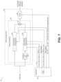
- FIG. 7shows a block diagram of radar processing system 700 , according to an embodiment of the present invention.
- Radar processing system 700includes radar processing chain 702 and coprocessor 704 .
- Radar processing chain 702includes radar pre-processing module 706 and tracking module 708 .
- Radar processing system 100may be implemented as radar processing system 700 .
- Radar processing chain 102may be implemented as radar processing chain 702 .
- Coprocessor 104may be implemented as coprocessor 704 .
- Hyperparameter selection neural network 105 and 205may be implemented as hyperparameter selection neural network 705 .
- radar processing system 700is configured to detect and track humans targets.
- Radar pre-processing module 706is used to detect one or more targets, which are tracked by tracking module 708 .
- Radar pre-processing module 706includes macro-Doppler processing chain 724 , and a micro-Doppler processing chain 724 .
- macro-Doppler processing chain 722 , and micro-Doppler processing chain 724may each be implemented in a similar manner as radar pre-processing module 506 or 606 , but operating at different frame rates.
- macro-Doppler processing chain 722processes the radar data at a frame rate equal to the frame rate of the radar data
- micro-Doppler detection processing chain 724processes the radar data at a frame rate lower than the frame rate of the radar data (e.g., every 32 frames of radar data).
- the micro framesare constructed ( 726 ) by sampling chirps from frames of the range data or from integrating chirps from frames of range data so that the micro frames have a slower frame rate (e.g., 32 times slower than the frames of range data).
- Macro-Doppler detection processing chain 722detects and identifies moving targets and high SNR static targets based on the radar data. For example, in some embodiments, macro detection processing chain 722 produces an output that includes a set of target parameters associated with the respective detected targets, where each target parameter includes data associated with range, Doppler velocity, and angle of the respective target.
- the set of target parametersdo not include target parameters associated with low motion, such as walls, since such targets may be removed, e.g., by MTI filtering, performed by macro detection processing chain 722 (e.g., since, even though a wall may be considered a high SNR object, fluctuations in the motion of a wall, if any, are too low to cause the retention of the wall as a target after MTI filtering).
- Micro detection processing chain 724detects and identifies static targets based on the radar data. For example, in some embodiments, micro detection processing chain 724 produces an output that includes a set of target parameters associated with the respective detected targets, where each target parameter includes data associated with range and angle of the respective target. In some embodiments, the target parameters generated by micro detection processing chain 724 do not include Doppler velocity, as it may be assumed to be 0 m/s (since the targets detected by micro detection processing chain 724 are static targets).
- micro-Doppler processing chain 724includes a micro-Doppler filter that filters the range FFTs with a pass-band corresponding to human vital signs (e.g., between 0.5 Hz and 5 Hz) before generating the range-Doppler maps ( 514 , 516 ).
- a micro-Doppler filterthat filters the range FFTs with a pass-band corresponding to human vital signs (e.g., between 0.5 Hz and 5 Hz) before generating the range-Doppler maps ( 514 , 516 ).
- tracking module 708may be implemented as an interactive multiple model (IMM) tracker. Other trackers may also be used.
- IMMinteractive multiple model
- coprocessor 704receives (e.g., using hyperparameter selection neural network 705 ) radar images (e.g., RAI and/or RDI before or after OS-CFAR) from detection processing chains 722 and 724 and updates one or more hyperparameters based on the received radar images.
- the hyperparameters provided by coprocessor 704 to macro-Doppler processing chain 722include probability of false alarm (P fa_macro ), number of reference cells (N ref_macro ), and number of guard cells (N guard_macro ), which are used by the OS-CFAR detector; and desired minimum cluster size (MinPts macro ) and neighborhood ( ⁇ macro ), which are used by DBSCAN algorithm.
- the hyperparameters provided by coprocessor 704 to micro-Doppler processing chain 724include probability of false alarm (P fa_micro ), number of reference cells (N ref_micro ), and number of guard cells (N guard_micro ), which are used by the OS-CFAR detector; desired minimum cluster size (MinPts micro ) and neighborhood ( ⁇ micro ), which are used by DBSCAN algorithm; and f L (lower cut-off frequency) and f H (higher cut-off frequency), which are used to configure the bandwidth of the micro-Doppler filter.
- P fa_microprobability of false alarm
- N ref_micronumber of reference cells
- N guard_micronumber of guard cells
- MinPts microdesired minimum cluster size
- ⁇ microneighborhood
- f Llower cut-off frequency
- f Hhigher cut-off frequency
- the hyperparameters provided by coprocessor 704 to tracking module 708include process and measurement covariance matrices Q and R, track start count and track kill count, and gating threshold.
- FIG. 8shows a block diagram of radar processing system 800 , according to an embodiment of the present invention.
- Radar processing system 800includes radar processing chain 802 and coprocessor 804 .
- Radar processing chain 802includes radar pre-processing module 806 and tracking module 808 .
- Radar processing system 100may be implemented as radar processing system 800 .
- Radar processing chain 102may be implemented as radar processing chain 802 .
- Coprocessor 104may be implemented as coprocessor 804 .
- Hyperparameter selection neural network 105 and 205may be implemented as hyperparameter selection neural network 805 .
- radar processing system 800is configured to detect and track a heartbeat rate of a human target.
- Radar pre-processing module 806is used to generate a displacement signal of a detected human target.
- the displacement signalis further processed by tracking module 708 , which uses Kalman filter to track the heartbeat rate of the human based on the processed displacement signal.
- Radar pre-processing module 806includes radar image generation 810 , which generates a radar image (e.g., RDI, RAI) based on the radar data.
- a radar imagee.g., RDI, RAI
- target movement detectionis performed ( 822 ), e.g., based on the standard deviation on the complex range data at the detected target range.
- an ellipse fitting algorithmis applied to the I-Q trace (of the complex range data) associated with the detected target to compensate for offset, amplitude, and gain errors.
- the compensated data(the compensated I-Q signals) are provided to a classifier ( 826 ), which estimates the quality of the compensated data and classifies the compensated data as “high quality” or “low quality” based on the random body movements (RBM) and/or intermodulation product (IMP) exhibited by the compensated data.
- the angle of the compensated target datais calculated ( 828 ) (e.g., by arctangent demodulation of the I-Q signals from the selected range bin) and the resulting phase values are unwrapped ( 830 ) between two consecutive data points for “high quality” compensated data to generate a displacement signal.
- Tracking module 808receives the displacement signal and filters it using band-pass (e.g., FIR) filter 832 .
- the heartbeat rate z k+1is estimated ( 834 ) based on the filtered displacement signal, where k+1 is indicative of the next time step of the Kalman filter.
- Kalman filteringmay be understood as a recursive Bayesian process, which may be applied when the measured values contain unpredictable or random errors, uncertainties or variations.
- the process of Kalman filteringincludes steps 836 , 838 , 840 , and 848 .
- the Kalman filtermakes a state prediction ( 836 ) based on the track associated with the heartbeat rate of the human target.
- An ellipsoidal gating functionchecks ( 838 ) whether the estimated heartbeat rate z k+1 is within a gating window.
- the state of the Kalman filteris updated ( 848 ) based on the first rate z k+1 and the band-pass filter settings are updated ( 852 ) (e.g., by narrowing the pass-band) based on the updated state.
- the state of the Kalman filteris not updated ( 840 ). If the state of the Kalman filter is not updated for M consecutive cycles, the band-pass filter settings are updated ( 846 ) (e.g., by increasing the pass-band).
- coprocessor 804receives (e.g., using hyperparameter selection neural network 805 ) radar images (e.g., RAI and/or RDI before or after OS-CFAR) from radar pre-processing module 806 and updates one or more hyperparameters based on the received radar images.
- radar imagese.g., RAI and/or RDI before or after OS-CFAR
- the hyperparameters provided by coprocessor 804 to m radar pre-processing module 806include probability of false alarm (P fa ), number of reference cells (N ref ), and number of guard cells (N guard ), which are used by the OS-CFAR detector ( 528 ); desired minimum cluster size (MinPts) and neighborhood ( ⁇ ), which are used by DBSCAN algorithm; and Quality_thres, which is used by classifier 826 to discriminate between high quality data and low quality data.
- the hyperparameters provided by coprocessor 804 to tracking module 808include process and measurement covariance matrices Q and R, threshold M, and gating threshold.
- radar image generation module 810may be implemented as modules 510 or 610 , for example.
- the hyperparameter selection neural network(e.g., 105 , 205 , 305 , 405 , 505 , 605 , 705 , 805 ) may be implemented with an input layer (e.g., 32 ⁇ 29 ⁇ 16), followed by three convolutional layers, followed by three dense layers. Other implementations, such as including one or more fully connected layers, are also possible.
- the hyperparameter selection neural network(e.g., 105 , 205 , 305 , 405 , 505 , 605 , 705 , 805 ) may be trained using one of or a combination of imitation learning, reinforcement learning, and cumulative learning. Other training methods may also be used.
- Advantages of some embodimentsinclude the capability of dynamically adapting one or more hyperparameters of the radar processing chain to optimize the radar performance, e.g., on a scene by scene basis. Adapting the hyperparameters of the radar processing chain based on the scene may advantageously result in better radar performance, e.g., when compared with radar processing chains that operate with fixed hyperparameters.
- FIG. 9 Ashows a block diagram illustrating embodiment method 900 for training a hyperparameter selection neural network (e.g., 105 , 205 , 305 , 405 , 505 , 605 , 705 , 805 ), according to an embodiment of the present invention.
- a hyperparameter selection neural networke.g., 105 , 205 , 305 , 405 , 505 , 605 , 705 , 805
- method 900may be implemented using reinforcement learning.
- main hyperparameter selection neural network 904generates a set H of probability distributions of hyperparameters based on the current radar processing output s (e.g., received from a radar processing chain, such as 102 , 202 , 302 , 402 , 502 , 602 , 702 , 802 ) according to the current policy ⁇ ( ) of the main hyperparameter selection neural network 904 .
- a radar processing chainsuch as 102 , 202 , 302 , 402 , 502 , 602 , 702 , 802
- Main critic neural network 906generates a Q-value Q(s,H) based on the current radar processing output s and the set of hyperparameters H generated by main hyperparameter selection neural network 904 , where the Q-value Q(s,H) is indicative of how good the set H is with respect to the current radar processing output s.
- a policy gradient algorithm 908is used based on the Q-value Q(s,H) to find the direction and magnitude of change of the coefficients of main hyperparameter selection neural network 904 .
- the coefficients of main hyperparameter selection neural network 904are updated based on the gradient ⁇ J determined by the policy gradient algorithm 908 .
- the policy gradient algorithm 908may be implemented in any way known in the art.
- Main critic neural network 906may be updated based on a Q-value generated based on the next radar processing output s′.
- the estimated value E[Q(s′,H′)] used in Equation 1is based on an estimate generated by man critic neural network 906 .
- Target critic neural network 916may generate Q(s′,H′) based on the set H′ of probability distribution of hyperparameters generated by target hyperparameter selection neural network 914 based on the next radar processing output s′.
- each of the hyperparameters of the set of hyperparameters H icorresponds to the peak value of their respective probability distributions.
- the main neural networks ( 904 and 906 )are updated during each training batch while the target networks ( 914 and 916 ) are updated every m updates of the main networks 904 and 906 (e.g., by copying the coefficients from networks 904 and 906 to 914 and 916 , respectively).
- mis 1000.
- each of the neural networks 904 , 906 , 914 , and 914may be implemented with an input layer (e.g., 32 ⁇ 29 ⁇ 16), followed by three convolutional layers, followed by three dense layers.
- an input layere.g., 32 ⁇ 29 ⁇ 16
- convolutional layerse.g., 32 ⁇ 29 ⁇ 16
- dense layerse.g., 3 ⁇ 29 ⁇ 16
- FIG. 9 Bshows a flow chart of embodiment method 900 for training a hyperparameter selection neural network, according to an embodiment of the present invention.
- FIG. 9 Bmay be understood in view of FIG. 9 A .
- main neural networks ( 904 and 906 ) and the target neural networks ( 914 and 916 )are initialized.
- main and target hyperparameter selection neural networks 904 and 914are initialized as identical networks
- main and target critic neural networks 906 and 916are initialized as identical networks.
- neural networks 904 , 906 , 914 and 916are initialized randomly.
- main and target hyperparameter selection neural networks 904 and 914may be initialized with pre-trained hyperparameter selection neural networks (e.g., trained using imitation learning). Some embodiments may initialize the main and target hyperparameter selection neural networks and/or the main and target critic networks in other ways.
- replay memory 902is initialized.
- replay memory 902is configured to store experiences e, where each experience e includes current and next radar processing output s and s′, the set H of hyperparameters generated by main hyperparameter selection neural network 904 based on s, and the reward value r.
- ⁇⁇ ⁇ ⁇ ⁇ ⁇ ⁇ ⁇ ⁇ ⁇ ⁇ ⁇ ⁇ ⁇ ⁇ ⁇ ⁇ ⁇ ⁇ ⁇ ⁇ ⁇ ⁇ ⁇ ⁇ ⁇ ⁇ ⁇ ⁇ ⁇ ⁇ ⁇ ⁇ ⁇ ⁇ ⁇ ⁇ ⁇ ⁇ ⁇ ⁇ ⁇ ⁇ ⁇ ⁇ ⁇ ⁇ ⁇ ⁇ ⁇ ⁇ ⁇ ⁇ ⁇ ⁇ ⁇ ⁇ ⁇ ⁇ ⁇ ⁇ ⁇ ⁇ ⁇ ⁇ ⁇ ⁇ ⁇ ⁇ ⁇ ⁇ ⁇ ⁇ ⁇ ⁇ ⁇ ⁇ ⁇ ⁇ ⁇ ⁇ ⁇ ⁇ ⁇ ⁇ ⁇ ⁇ ⁇ ⁇ ⁇ ⁇ ⁇ ⁇ ⁇ ⁇ ⁇ ⁇ ⁇ ⁇ ⁇ ⁇ ⁇ ⁇ ⁇ ⁇ ⁇ ⁇ ⁇ ⁇ ⁇ ⁇ ⁇ ⁇ ⁇ ⁇ ⁇ ⁇ ⁇ ⁇ ⁇ ⁇ ⁇ ⁇ ⁇ ⁇ ⁇
- the outputs generated by the radar processing chainare fed to the main and target neural networks ( 904 , 906 , 914 , and 916 ), and outputs from the neural networks ( 904 , 906 , 914 , and 916 ), together with other associated data (e.g., r) are stored in the replay buffer.
- experiences from replay bufferare (e.g., randomly) sampled.
- the sampled experiencesare used to compute TD loss L ( 918 ) using, e.g., Equation 2, during step 930 .
- main hyperparameter selection neural network 904is updated using a policy gradient algorithm ( 908 ).
- steps 936 and 938in some embodiments, steps 928 , 930 , 932 , and 934 are repeated T times, where T is larger than 1, such as 100, 1000, or more.
- steps 940 and 942the main neural networks ( 904 , 906 ) are copied to the respective target networks ( 914 , 916 ) every T iteration steps.
- the target neural networks ( 914 , 916 )are updated every T updates of the main neural networks ( 904 , 906 ).
- target hyperparameter selection neural network 914is copied into a coprocessor (e.g., to become hyperparameter selection neural network 105 , 205 , 305 , 405 , 505 , 605 , 705 , 805 ) to be used in inference mode.
- the copied hyperparameter selection neural networkdeactivates the feature of outputting the set H of probability distribution of hyperparameters and instead provides the set H i of specific hyperparameters.
- the hyperparameter selection neural network(e.g., 105 , 205 , 305 , 405 , 505 , 605 , 705 , 805 ) outputs a set H i of specific hyperparameters based on the radar processing input (s) received by the radar processing chain (e.g., 102 , 202 , 302 , 402 , 502 , 602 , 702 , 802 ).
- the reward re.g., used to compute the TD loss function ( 918 ), e.g., using Equation 2, may be given by
- T Nrepresents the number of targets present in the radar processing data s
- errDist irepresents the distance between a prediction of the tracker (e.g., 108 , 208 , 308 , 408 , 508 , 608 , 708 , 808 ) and the closest detected target
- the reward rmay be given by
- Equation 5maxCondPPres represents the highest condition number in the matrix of prediction of the tracker.
- the distance errDist iis the Euclidean distance between the prediction of the tracker and the closest detected target.
- using a Mahalanobis distancemay advantageously take into account the distribution of the prediction of the tracker, which may advantageously provide a better distance metric than Euclidean distance.
- Other distance functions, such as the Mahalanobis distancemay be used.
- the distance errDist iis based on labels associated with the radar processing output s.
- the distance errDist iis the distance (e.g., Euclidean, Mahalanobis) between the tracker prediction and the location of target according to label data.
- the label datais generated by capturing frames with a radar sensor of a scene and, simultaneously, capturing data, e.g., with a video camera and/or other sensors, of the same scene. Other methods for generating the labeled data may also be used.
- the Q-value function Q(s,H) generated by a critic neural networkmay be given by Q ( s,H
- ⁇ Q )A ( s,H
- V( )represents a value function indicative of a value of radar processing output s
- A( )represents an advantage function indicative of the relative quality of H relative to the average quality of possible hyperparameters that can be selected
- the advantage functionmay be given by A ( s,H
- ⁇ A )⁇ 1 ⁇ 2( u ⁇ ( s
- ⁇ ( )represents the policy of hyperparameter selection neural network 904
- ⁇ P )is a state dependent square matrix that may be given by P ( s
- ⁇ P )L ( s
- ⁇ L )is a lower triangular matrix
- ⁇ ⁇represents the parameters of the hyperparameter selection neural network 904
- ⁇ Lrepresents the parameters of a lower triangular neural network producing the values of the lower triangular matrix L(s
- FIG. 9 Cshows a block diagram illustrating embodiment method 950 for training a hyperparameter selection neural network (e.g., 105 , 205 , 305 , 405 , 505 , 605 , 705 , 805 ), according to an embodiment of the present invention.
- FIG. 9 Cmay be understood in view of Equations 6-9.
- main hyperparameter selection neural network 904implements the policy function ⁇ ( ) (which is used to generate the set H of hyperparameters), lower triangular neural network 952 provides the elements of the lower triangular function matrix L(s
- Neural networks 952 , 954 , and 956may be referred to as critic neural networks.
- the Q-value termis generated based on Equations 6-9 using main hyperparameter selection neural network 904 , lower triangular neural network 952 , and main value neural network 954 .
- Target value neural network 956implements the value function V( ) and operates based on the next radar processing output s′.
- target value neural network 956is updated in a time delayed manner by copying the coefficients from main value neural network 954 .
- the neural networks 904 , 952 , and 954are updated during each training batch while neural network 956 is updated every m updates of the neural networks 904 , 952 , and 954 .
- each of the neural networks 904 , 952 , 954 , and 956may be implemented with an input layer (e.g., 32 ⁇ 29 ⁇ 16), followed by three convolutional layers, followed by three dense layers. Other implementations, such as including one or more fully connected layers, are also possible.
- methods 900 and 950may be implemented using curriculum learning.
- the radar processing outputs s provided to the neural networkse.g., 904 , 906 , 914 , and 916 ; or 904 , 952 , and 956 ) are provided in a sequence of increasing complexity.
- the first iterations of the loop including steps 928 , 930 , 932 , 934 , 936 , 938 , 940 , and 942include only radar processing outputs s corresponding to 0 targets; the next iterations of the loop may include only radar processing outputs s corresponding to 0 and 1 targets; the following iterations of the loop may include only radar processing outputs s corresponding to 0, 1, and 2 targets; etc.
- the mini-batches of lower complexityare fed first during training, followed by mini-batches of increasing complexity (e.g., 0 and 1 targets; 0, 1, and 2 targets; etc.).
- complexitymay be increased in other ways, such as by increasing clutter in the environment, increasing the size of the field-of-view, etc.
- some embodimentsadvantageously achieved faster learning time/convergence compared to presenting the radar processing outputs in a random manner.
- the hyperparameter selection neural network(e.g., 105 , 205 , 305 , 405 , 505 , 605 , 705 , 805 ) is trained in multiple phases.
- FIG. 10shows a flow chart of embodiment method 1000 for training a hyperparameter selection neural network, according to an embodiment of the present invention.
- the hyperparameter selection neural network(e.g., 904 ) is trained.
- the hyperparameter selection neural networkis trained using imitation learning.
- manually selected hyperparametersare paired with radar processing outputs s.
- a loss functionmay be defined as the difference between the manually selected hyperparameters and the hyperparameters produced by hyperparameter selection neural network 904 .
- the coefficients of the hyperparameter selection neural networkare iteratively adjusted based on the loss function (e.g., to minimize the difference between the manually selected hyperparameters and the hyperparameters produced by hyperparameter selection neural network 904 ).
- using imitation learning before performing phase II ( 1004 ) and phase III ( 1006 ) trainingadvantageously a hyperparameter neural network that provides a good initial set H of hyperparameters, which may result in faster training/convergence time.
- the critic neural networkis trained during phase II ( 1004 ).
- the hyperparameter selection neural networks 904 and 914are fixed (e.g., equal to the trained hyperparameter selection neural network after phase I), and the critic neural networks ( 906 and 916 ) are trained.
- method 900is performed to train the critic neural networks ( 906 and 916 ) while keeping constant the hyperparameter selection neural networks (e.g., during steps 934 and 940 ).
- the hyperparameter selection neural networks 904is fixed (e.g., equal to the trained hyperparameter selection neural network after phase I), and neural networks 952 , 954 , and 956 , are trained.
- the hyperparameter selection neural network and the critic neural networkare trained during phases I ( 1002 ) and II ( 1004 ), respectively, the hyperparameter selection neural network and the critic neural network are jointly trained during phase III ( 1006 ).
- the hyperparameter selection neural network and the critic neural networkare jointly trained during phase III ( 1006 ) by performing method 900 or 950 .
- method 900 or 950may be performed using curriculum learning (e.g., by increasing the complexity of the radar processing outputs as the training progresses).
- phase III1006
- phases I1002
- phases I1002
- II1004
- Other implementationsare also possible.
- FIGS. 11 A and 11 Billustrate a comparison between a scene-based radar (as implemented as shown in FIG. 8 ) versus a baseline radar, according to an embodiment of the present invention.
- the scene-based radarincludes a radar processing chain and a hyperparameter selection neural network trained using method 1000 to dynamically provide hyperparameters to the radar processing chain.
- the baseline radaroperates with fixed hyperparameters.
- dynamically adjusting the hyperparameters of the radar processing chainadvantageously results in superior radar performance when compared to using fixed hyperparameters, as indicated by the higher average reward r (which is used here as a metric to evaluate performance) and lower errorDet exhibited by the scene-based radar, as compared to the baseline radar.
- FIG. 12shows a schematic diagram of millimeter-wave radar system 1200 , according to an embodiment of the present invention.
- Millimeter-wave radar system 1200includes millimeter-wave radar sensor 1202 and processing system 1204 .
- millimeter-wave radar sensor 1202may be used to generate radar data (x out_dig (n)) and processing system 1204 may implement a radar processing chain (e.g., 102 , 202 , 302 , 402 , 502 , 602 , 702 , 802 ) and a coprocessor (e.g., 104 , 204 , 304 , 404 , 504 , 604 , 704 , 804 ).
- a radar processing chaine.g., 102 , 202 , 302 , 402 , 502 , 602 , 702 , 802
- coprocessore.g., 104 , 204 , 304 , 404 , 504 , 604
- millimeter-wave radar sensor 1202operates as a frequency-modulated continuous-wave (FMCW) radar sensor and transmits a plurality of TX radar signals 1206 , such as chirps, towards scene 1220 using one or more transmitter (TX) antenna 1214 .
- the radar signals 1206are generated using RF and analog circuits 1230 .
- the radar signals 1206may be, e.g., in the 20 GHz to 122 GHz range. Other frequencies may also be used.
- the objects in scene 1220may include one or more static or moving objects, such as cars, motorcycles, bicycles, trucks, and other vehicles, idle and moving humans and animals, furniture, machinery, mechanical structures, walls and other types of structures. Other objects may also be present in scene 1220 .
- the radar signals 1206are reflected by objects in scene 920 .
- the reflected radar signals 1208which are also referred to as the echo signal, are received by one or more receiving (RX) antennas 916 .
- RF and analog circuits 1230processes the received reflected radar signals 1208 using, e.g., band-pass filters (BPFs), low-pass filters (LPFs), mixers, low-noise amplifier (LNA), and/or intermediate frequency (IF) amplifiers in ways known in the art to generate an analog signal x out (t).
- BPFsband-pass filters
- LPFslow-pass filters
- LNAlow-noise amplifier
- IFintermediate frequency
- the analog signal x out (t)is converted to raw digital data x out_dig (n) (also referred to as radar data) using ADC 1212 .
- the raw digital data x out_dig (n)is processed by processing system 1204 to, e.g., detect and track targets. In some embodiments, processing system 1204 may be used to identify and classify targets.
- Controller 1210controls one or more circuits of millimeter-wave radar sensor 1202 , such as RF and analog circuit 1230 and/or ADC 1212 .
- Controller 1210may be implemented, e.g., as a custom digital or mixed signal circuit, for example. Controller 1210 may also be implemented in other ways, such as using a general purpose processor or controller, for example. In some embodiments, processing system 104 implements a portion or all of controller 1210 .
- Processing system 1204may be implemented with a general purpose processor, controller or digital signal processor (DSP) that includes, for example, combinatorial circuits coupled to a memory.
- processing system 1204may be implemented as an application specific integrated circuit (ASIC).
- processing system 904may be implemented with an ARM, RISC, or x86 architecture, for example.
- processing system 1204may include an artificial intelligence (AI) accelerator.
- AIartificial intelligence
- Some embodimentsmay use a combination of hardware accelerator and software running on a DSP or general purpose microcontroller.
- processing system 1204may be implemented with a plurality of processors and/or controllers. Other implementations are also possible.
- processing system 1204implements the radar processing chain (e.g., 102 , 202 , 302 , 402 , 502 , 602 , 702 , 802 ) in a DSP or microcontroller, and the coprocessor (e.g., 104 , 204 , 304 , 404 , 504 , 604 , 704 , 804 ) in an AI accelerator.
- the coprocessore.g., 104 , 204 , 304 , 404 , 504 , 604 , 704 , 804
- Other implementationsare also possible.
- millimeter-wave radar sensor 1202 and a portion or all of processing system 1204may be implemented inside the same integrated circuit (IC).
- ICintegrated circuit
- millimeter-wave radar sensor 1202 and a portion or all of processing system 1204may be implemented in respective semiconductor substrates that are integrated in the same package.
- millimeter-wave radar sensor 1202 and a portion or all of processing system 1204may be implemented in the same monolithic semiconductor substrate.
- millimeter-wave radar sensor 1202 and processing system 1204are implemented in respective integrated circuits.
- a plurality of integrated circuitsis used to implement millimeter-wave radar sensor 1202 .
- a plurality of integrated circuitsis used to implement processing system 1204 .
- Other implementationsare also possible.
- RF and analog circuits 1230may be implemented, e.g., as shown in FIG. 12 .
- VCOvoltage-controlled oscillator
- PLL 1234receives a reference clock signal (e.g., 80 MHz) from reference oscillator 1232 .
- PLL 1234is controlled by a loop that includes frequency divider 1238 and amplifier 1240 .
- Amplifier 1237may be used to drive transmitting antenna 1214 .
- the TX radar signals 1206 transmitted by transmitting antenna 1214are reflected by objects in scene 1220 and received by receiving antenna 1216 .
- the echo received by receiving antenna 1216is mixed with a replica of the signal transmitted by transmitting antenna 1214 using mixer 1246 to produce intermediate frequency (IF) signal x IF (t) (also known as beat signal).
- IFintermediate frequency
- x IF (t)also known as beat signal
- the beat signal x IF (t)has a bandwidth between 10 kHz and 1 MHz. Beat signals with a bandwidth lower than 10 kHz or higher than 1 MHz is also possible.
- Amplifier 1245may be used to receive the reflected radar signals from antenna 1216 .
- Beat signal x IF (t)is filtered with low-pass filters (LPF) 1248 and then sampled by ADC 1212 .
- ADC 1212is advantageously capable of sampling the filtered beat signal x out (t) with a sampling frequency that is much smaller than the frequency of the signal received by receiving antenna 1216 .
- FMCW radarstherefore, advantageously allows for a compact and low cost implementation of ADC 1212 , in some embodiments.
- the raw digital data x out_dig (n), which in some embodiments include the digitized version of the filtered beat signal x out (t)is (e.g., temporarily) stored, e.g., in matrices of N c ⁇ N s per receiving antenna 1216 , where N c is the number of chirps considered in a frame and N s is the number of transmit samples per chirp, for further processing by processing system 1204 .
- FIG. 13shows a sequence of chirps 1206 transmitted by TX antenna 1214 , according to an embodiment of the present invention.
- chirps 1206are organized in a plurality of frames and may be implemented as up-chirps. Some embodiments may use down-chirps or a combination of up-chirps and down-chirps, such as up-down chirps and down-up chirps. Other waveform shapes may also be used.
- each framemay include a plurality of chirps 1206 .
- the number of chirps in a frameis 16.
- Some embodimentsmay include more than 16 chirps per frame, such as 20 chirps, 32 chirps, or more, or less than 16 chirps per frame, such as 10 chirps, 8 chirps, or less.
- each frameincludes only a single chirp.
- framesare repeated every FT time.
- FT timeis 50 ms.
- a different FT timemay also be used, such as more than 50 ms, such as 60 ms, 100 ms, 200 ms, or more, or less than 50 ms, such as 45 ms, 40 ms, or less.
- the FT timeis selected such that the time between the beginning of the last chirp of frame n and the beginning of the first chirp of frame n+1 is equal to PRT.
- Other embodimentsmay use or result in a different timing.
- the time between chirps of a frameis generally referred to as pulse repetition time (PRT).
- PRTpulse repetition time
- the PRTis 5 ms.
- a different PRTmay also be used, such as less than 5 ms, such as 4 ms, 2 ms, or less, or more than 5 ms, such as 6 ms, or more.
- the duration of the chirp(from start to finish) is generally referred to as chirp time (CT).
- CTchirp time
- the chirp timemay be, e.g., 64 ⁇ s. Higher chirp times, such as 128 ⁇ s, or higher, may also be used. Lower chirp times, may also be used.
- the chirp bandwidthmay be, e.g., 4 GHz. Higher bandwidth, such as 6 GHz or higher, or lower bandwidth, such as 2 GHz, 1 GHz, or lower, may also be possible.
- the sampling frequency of millimeter-wave radar sensor 902may be, e.g., 1 MHz. Higher sampling frequencies, such as 2 MHz or higher, or lower sampling frequencies, such as 500 kHz or lower, may also be possible.
- the number of samples used to generate a chirpmay be, e.g., 64 samples.
- Example 1A method including: receiving first radar data from a millimeter-wave radar sensor; receiving a set of hyperparameters with a radar processing chain; generating a first radar processing output using the radar processing chain based on the first radar data and the set of hyperparameters; updating the set of hyperparameters based on the first radar processing output using a hyperparameter selection neural network; receiving second radar data from the millimeter-wave radar sensor; and generating a second radar processing output using the radar processing chain based on the second radar data and the updated set of hyperparameters.
- Example 2The method of example 1, where the first radar processing output includes a first radar image.
- Example 3The method of one of examples 1 or 2, further including generating the first radar image using the radar processing chain based on an aggregation of a last m frames of the first radar data, where m is a positive integer greater than 1 and lower than or equal to 32.
- Example 4The method of one of examples 1 to 3, further including generating the first radar image by masking a range-angle image (RAI) or range-Doppler image (RDI) based on an output of an order statistics (OS) constant false alarm rate (CFAR) (OS-CFAR) detector.
- RAIrange-angle image
- RDIrange-Doppler image
- OS-CFARconstant false alarm rate
- Example 5The method of one of examples 1 to 4, where the set of hyperparameters includes a probability of false alarm hyperparameter, a number of reference cells hyperparameter and a number of guard cell hyperparameter, where receiving the set of hyperparameters includes receiving the probability of false alarm hyperparameter, the number of reference cells hyperparameter, and the number of guard cell hyperparameter with the OS-CFAR detector.
- Example 6The method of one of examples 1 to 5, further including, generating a heatmap with a tracker of the radar processing chain, and where the first radar processing output includes the heatmap.
- Example 7The method of one of examples 1 to 6, where the radar processing chain includes a tracker, where the set of hyperparameters includes a gating threshold hyperparameter, and where receiving the set of hyperparameters includes receiving the gating threshold hyperparameter with the tracker.
- Example 8The method of one of examples 1 to 7, where the tracker includes an unscented Kalman filter.
- Example 9The method of one of examples 1 to 8, further including training the hyperparameter selection neural network.
- Example 10The method of one of examples 1 to 9, where training the hyperparameter selection neural network includes training the hyperparameter selection neural network using imitation learning.
- Example 11The method of one of examples 1 to 10, where training the hyperparameter selection neural network further includes, after training the hyperparameter selection neural network using imitation learning, training the hyperparameter selection neural network using reinforcement learning.
- Example 12The method of one of examples 1 to 11, where training the hyperparameter selection neural network using reinforcement learning includes using a value neural network for providing a value function and a lower triangular neural network for providing a lower triangular matrix, where a Q function is based on the value function and the lower triangular matrix.
- Example 13The method of one of examples 1 to 12, where training the hyperparameter selection neural network further includes using curriculum learning during reinforcement learning.
- Example 14The method of one of examples 1 to 13, further including using a reward function based on missed detections, false alarms, and error distances between predicted and actual target locations during reinforcement learning.
- Example 15The method of one of examples 1 to 14, further including determining the error distances using Mahalanobis distances between predicted and actual target locations.
- Example 16The method of one of examples 1 to 15, further including determining the error distances using Euclidean distances between predicted and actual target locations.
- Example 17A method including: receiving first radar data from a millimeter-wave radar sensor; receiving a set of hyperparameters with a radar processing chain including a tracker; generating a first radar image using the radar processing chain based on the first radar data and the set of hyperparameters; tracking a target using the tracker based on the first radar image and the set of hyperparameters; updating the set of hyperparameters based on the first radar image using a hyperparameter selection neural network; receiving second radar data from the millimeter-wave radar sensor; and generating a second radar image using the radar processing chain based on the second radar data and the updated set of hyperparameters.
- Example 18The method of example 17, where the target is a human target.
- Example 19The method of one of examples 17 or 18, where the target is a heartbeat rate of a human.
- Example 20The method of one of examples 17 to 19, where the tracker includes a Kalman filter.
- Example 21A millimeter-wave radar system including: a millimeter-wave radar sensor configured to transmit radar signals and receive reflected radar signals, and generate radar data based on the reflected radar signals; and a processing system including: a radar processing chain configured to generate a first radar processing output based on the radar data and a set of hyperparameters, and a hyperparameter selection neural network configured to update the set of hyperparameters based on the first radar processing output, where the radar processing chain is configured to generate a second radar processing output based on the radar data and the updated set of hyperparameters.
- Example 22The millimeter-wave radar system of example 21, where the radar processing chain is configured to track a target based on the radar data.
- Example 23The millimeter-wave radar system of one of examples 21 or 22, where the radar data includes a plurality of consecutive frames, and where the hyperparameter selection neural network is configured to update the set of hyperparameters every n frames of the radar data, where n is a positive integer greater than or equal to 1.
- Example 24The millimeter-wave radar system of one of examples 21 to 23, where the hyperparameter selection neural network includes an initial layer, a plurality of convolutional layers, and a plurality of dense layers.
- Example 25The millimeter-wave radar system of one of examples 21 to 24, where the first radar processing output includes a radar image and a masked radar image.
Landscapes
- Engineering & Computer Science (AREA)
- Physics & Mathematics (AREA)
- Theoretical Computer Science (AREA)
- General Physics & Mathematics (AREA)
- Remote Sensing (AREA)
- Evolutionary Computation (AREA)
- Artificial Intelligence (AREA)
- Radar, Positioning & Navigation (AREA)
- Biophysics (AREA)
- Mathematical Physics (AREA)
- General Health & Medical Sciences (AREA)
- Molecular Biology (AREA)
- Computing Systems (AREA)
- General Engineering & Computer Science (AREA)
- Computational Linguistics (AREA)
- Data Mining & Analysis (AREA)
- Software Systems (AREA)
- Biomedical Technology (AREA)
- Life Sciences & Earth Sciences (AREA)
- Health & Medical Sciences (AREA)
- Computer Networks & Wireless Communication (AREA)
- Electromagnetism (AREA)
- Multimedia (AREA)
- Radar Systems Or Details Thereof (AREA)
Abstract
Description
Q(s,H)=E[r+γE[Q(s′,H′)]] (1)
where E[ ] represents the expected value function, r represents the reward, γ represents a discount factor (which may be between 0 and 1), and Q-value Q(s′,H′) is the Q-value based on the next radar processing output s′. However, the estimated value E[Q(s′,H′)] used in
L=E[r+γQ(s′,H′)−Q(s,Hi)] (2)
where Hiis a set of specific hyperparameters that corresponds to, e.g., optimal specific hyperparameters selected from the probability distributions of the hyperparameters of set H. In some embodiments, each of the hyperparameters of the set of hyperparameters Hicorresponds to the peak value of their respective probability distributions.
where TNrepresents the number of targets present in the radar processing data s, errDistirepresents the distance between a prediction of the tracker (e.g.,108,208,308,408,508,608,708,808) and the closest detected target, factorVal represents a factor, which may be a real number, such as between 1 and 5, such as 2, and errDet is indicative of target detection errors, and may be given by
errDet=misDets+falseAlarms (4)
where misDets represents the number of misdetections (e.g., targets that are present in radar processing output s but that are not detected by the tracker (e.g.,108,208,308,408,508,608,708,808)), and falseAlarms represents the number of false alarms (e.g., targets that are not present in radar processing output s but that are detected by the tracker (e.g.,108,208,308,408,508,608,708,808)).
where maxCondPPres represents the highest condition number in the matrix of prediction of the tracker. When applying
Q(s,H|θQ)=A(s,H|θA)+V(s|θV) (6)
where V( ) represents a value function indicative of a value of radar processing output s, A( ) represents an advantage function indicative of the relative quality of H relative to the average quality of possible hyperparameters that can be selected, and θQ, θA, and θVparametrizes functions Q( ), A( ), and V( ), respectively, so that θQ=θA∪θV.
A(s,H|θA)=−½(u−μ(s|θμ))TP(s|θP)(u−μ(s|θμ)) (7)
where μ( ) represents the policy of hyperparameter selection
u=μ(s|θμ)+N (8)
where N represents exploration noise, and P(s|θP) is a state dependent square matrix that may be given by
P(s|θP)=L(s|θL)L(s|θL)T (9)
where L(s|θL) is a lower triangular matrix, where θμrepresents the parameters of the hyperparameter selection
L=E[(Q(s,H)−(r+γV(s′)))2] (10)
where the gradient of the TD loss function of Equation 10 may be calculated by
∇L=∇E[(Q(s,H)−(r+γV(s′)))2]=E[2(Q(s,H)−(r+γV(s′)))∇Q(s,H)] (11).
Claims (26)
Priority Applications (3)
| Application Number | Priority Date | Filing Date | Title |
|---|---|---|---|
| US17/396,032US12307761B2 (en) | 2021-08-06 | 2021-08-06 | Scene-adaptive radar |
| EP22188672.4AEP4130782A3 (en) | 2021-08-06 | 2022-08-04 | Scene-adaptive radar |
| CN202210937009.XACN115704891A (en) | 2021-08-06 | 2022-08-05 | Scene adaptive radar |
Applications Claiming Priority (1)
| Application Number | Priority Date | Filing Date | Title |
|---|---|---|---|
| US17/396,032US12307761B2 (en) | 2021-08-06 | 2021-08-06 | Scene-adaptive radar |
Publications (2)
| Publication Number | Publication Date |
|---|---|
| US20230040007A1 US20230040007A1 (en) | 2023-02-09 |
| US12307761B2true US12307761B2 (en) | 2025-05-20 |
Family
ID=82839076
Family Applications (1)
| Application Number | Title | Priority Date | Filing Date |
|---|---|---|---|
| US17/396,032Active2043-07-22US12307761B2 (en) | 2021-08-06 | 2021-08-06 | Scene-adaptive radar |
Country Status (3)
| Country | Link |
|---|---|
| US (1) | US12307761B2 (en) |
| EP (1) | EP4130782A3 (en) |
| CN (1) | CN115704891A (en) |
Families Citing this family (2)
| Publication number | Priority date | Publication date | Assignee | Title |
|---|---|---|---|---|
| CN117930142B (en)* | 2024-03-20 | 2024-06-07 | 哈尔滨工业大学(威海) | Radar waveform design method for coping with high sea state sea surface maneuvering target tracking |
| CN119508151A (en)* | 2024-10-28 | 2025-02-25 | 北京航天嘉诚精密科技发展有限公司 | Fan blade clearance distance monitoring system capable of measuring rotation speed and speed measurement method thereof |
Citations (143)
| Publication number | Priority date | Publication date | Assignee | Title |
|---|---|---|---|---|
| US4241347A (en) | 1978-06-28 | 1980-12-23 | International Telephone And Telegraph Corporation | PRC/FM CW Radar system |
| GB2247799A (en) | 1990-09-04 | 1992-03-11 | Gec Ferranti Defence Syst | Radar based navigation aid |
| US6147572A (en) | 1998-07-15 | 2000-11-14 | Lucent Technologies, Inc. | Filter including a microstrip antenna and a frequency selective surface |
| JP2001174539A (en) | 1999-10-06 | 2001-06-29 | Nec Corp | Multi-beam ladar device |
| US20030179127A1 (en) | 2000-07-28 | 2003-09-25 | Hans-Theo Wienand | People counter |
| US6636174B2 (en) | 2000-06-06 | 2003-10-21 | Altratek Inc. | System and method for detection and tracking of targets |
| CN1463161A (en) | 2002-06-01 | 2003-12-24 | 三星电子株式会社 | Device and method of correcting image movement |
| JP2004198312A (en) | 2002-12-19 | 2004-07-15 | Mitsubishi Electric Corp | Radar equipment |
| US20040238857A1 (en) | 2001-08-28 | 2004-12-02 | Tessera, Inc. | High frequency chip packages with connecting elements |
| CN1716695A (en) | 2004-06-30 | 2006-01-04 | 国际商业机器公司 | Apparatus and methods for constructing and packaging printed antenna devices |
| US20060049995A1 (en) | 2004-09-01 | 2006-03-09 | Toshikazu Imaoka | Integrated antenna type circuit apparatus |
| US20060067456A1 (en) | 2004-09-27 | 2006-03-30 | Point Grey Research Inc. | People counting systems and methods |
| US7048973B2 (en) | 2001-08-08 | 2006-05-23 | Mitsubishi Heavy Industries, Ltd. | Metal film vapor phase deposition method and vapor phase deposition apparatus |
| US7057564B2 (en) | 2004-08-31 | 2006-06-06 | Freescale Semiconductor, Inc. | Multilayer cavity slot antenna |
| JP2006234513A (en) | 2005-02-23 | 2006-09-07 | Toyota Central Res & Dev Lab Inc | Obstacle detection device |
| WO2007060069A1 (en) | 2005-11-28 | 2007-05-31 | Nokia Siemens Networks Gmbh & Co. Kg | Method and arrangement for calibrating transmit paths of an antenna array |
| US20070210959A1 (en) | 2006-03-07 | 2007-09-13 | Massachusetts Institute Of Technology | Multi-beam tile array module for phased array systems |
| US7317417B2 (en) | 2004-07-12 | 2008-01-08 | Orhan Arikan | Methods for detection and tracking of targets |
| JP2008029025A (en) | 2002-06-27 | 2008-02-07 | Harris Corp | Highly efficient resonance line |
| JP2008089614A (en) | 2007-12-27 | 2008-04-17 | Hitachi Ltd | Radar sensor |
| US20080106460A1 (en) | 2006-06-01 | 2008-05-08 | James Lynn Kurtz | Radar microsensor for detection, tracking, and classification |
| US20080238759A1 (en) | 2007-03-30 | 2008-10-02 | Honeywell International Inc. | Integrated distance measuring equipment and transponder system and method |
| US20080291115A1 (en) | 2007-05-22 | 2008-11-27 | Sibeam, Inc. | Surface mountable integrated circuit packaging scheme |
| US20080308917A1 (en) | 2007-06-13 | 2008-12-18 | Infineon Technologies Ag | Embedded chip package |
| US20090073026A1 (en) | 2007-09-18 | 2009-03-19 | Mitsubishi Electric Corporation | Radar apparatus |
| US20090085815A1 (en) | 2007-09-27 | 2009-04-02 | Jakab Andrew J | Tightly-coupled pcb gnss circuit and manufacturing method |
| KR20090063166A (en) | 2007-12-12 | 2009-06-17 | 브로드콤 코포레이션 | Method and system for phased array antenna embedded in integrated circuit package |
| CN101490578A (en) | 2006-07-13 | 2009-07-22 | 罗伯特·博世有限公司 | FMCW-radarsensor |
| US7596241B2 (en) | 2005-06-30 | 2009-09-29 | General Electric Company | System and method for automatic person counting and detection of specific events |
| CN101585361A (en) | 2009-05-25 | 2009-11-25 | 郭文艺 | Anti-collision and lane-departure-prevention control device for automobile |
| DE102008054570A1 (en) | 2008-12-12 | 2010-06-17 | Robert Bosch Gmbh | FMCW radar sensor for motor vehicles |
| US20100207805A1 (en) | 2009-02-19 | 2010-08-19 | Agd Systems Limited | Obtaining an indication of a number of moving objects passing speed detection apparatus |
| US7873326B2 (en) | 2006-07-11 | 2011-01-18 | Mojix, Inc. | RFID beam forming system |
| US7889147B2 (en) | 2007-02-23 | 2011-02-15 | Northrop Grumman Systems Corporation | Modular active phased array |
| JP2011529181A (en) | 2008-07-24 | 2011-12-01 | コーニンクレッカ フィリップス エレクトロニクス エヌ ヴィ | Distance measurement |
| US20110299433A1 (en) | 2010-06-03 | 2011-12-08 | Broadcom Corporation | Rf front-end module |
| DE102011100907A1 (en) | 2011-05-09 | 2012-01-12 | Daimler Ag | Device for determining road condition of roadway located in front of vehicle, comprises imaging sensor for detecting road surface, and evaluation unit for evaluation of image data |
| US20120087230A1 (en) | 2009-06-17 | 2012-04-12 | Telefonaktiebolaget Lm Ericsson (Publ) | Method For Antenna Calibration In A Wideband Communication System |
| US20120092284A1 (en) | 2010-09-30 | 2012-04-19 | Broadcom Corporation | Portable computing device including a three-dimensional touch screen |
| US20120116231A1 (en) | 2009-05-18 | 2012-05-10 | Perception Digital Limited | Earplug-type earphone |
| JP2012112861A (en) | 2010-11-26 | 2012-06-14 | Fujitsu Ltd | Fm-cw radar device and pairing method |
| US8228382B2 (en) | 2005-11-05 | 2012-07-24 | Ram Pattikonda | System and method for counting people |
| US20120195161A1 (en) | 2005-05-03 | 2012-08-02 | Sonosite, Inc. | Systems and methods for ultrasound beam forming data control |
| US20120206339A1 (en) | 2009-07-07 | 2012-08-16 | Elliptic Laboratories As | Control using movements |
| US20120265486A1 (en) | 2009-12-23 | 2012-10-18 | Endress + Hauser Gmbh + Co. Kg | Method for ascertaining and monitoring fill level of a medium in a container with a travel time measuring method |
| US20120268314A1 (en) | 2011-02-11 | 2012-10-25 | Honda Elesys Co., Ltd. | Multibeam radar apparatus for vehicle, multibeam radar method, and multibeam radar program |
| US20120280900A1 (en) | 2011-05-06 | 2012-11-08 | Nokia Corporation | Gesture recognition using plural sensors |
| DE102011075725A1 (en) | 2011-05-12 | 2012-11-15 | Robert Bosch Gmbh | Method for recognizing gestures |
| CN102788969A (en) | 2012-07-04 | 2012-11-21 | 中国人民解放军海军航空工程学院 | Sea surface micromotion target detection and feature extraction method based on short-time fractional Fourier transform |
| WO2013009473A2 (en) | 2011-07-12 | 2013-01-17 | Sensormatic Electronics, LLC | Method and system for people counting using passive infrared detectors |
| US20130027240A1 (en) | 2010-03-05 | 2013-01-31 | Sazzadur Chowdhury | Radar system and method of manufacturing same |
| CN102967854A (en) | 2012-12-07 | 2013-03-13 | 中国人民解放军海军航空工程学院 | Multi-fractal detection method of targets in FRFT (Fractional Fourier Transformation) domain sea clutter |
| US20130106673A1 (en) | 2011-10-20 | 2013-05-02 | Waveconnex, Inc. | Low-profile wireless connectors |
| CN103529444A (en) | 2013-09-27 | 2014-01-22 | 安徽师范大学 | A vehicle-mounted millimeter-wave radar moving target recognizer and recognition method |
| US20140028542A1 (en) | 2012-07-30 | 2014-01-30 | Microsoft Corporation | Interaction with Devices Based on User State |
| US20140050368A1 (en)* | 2006-05-02 | 2014-02-20 | Geoeye Solutions, Inc. | Semi-automatic extraction of linear features from image data including path width attribution |
| US8659369B2 (en) | 2007-12-13 | 2014-02-25 | Broadcom Corporation | IC package with embedded filters |
| US20140070994A1 (en) | 2012-09-13 | 2014-03-13 | Toyota Motor Engineering & Manufacturing North America, Inc. | 3d short range detection with phased array radar |
| US8731502B2 (en) | 2009-02-13 | 2014-05-20 | Freescale Semiconductor, Inc. | Integrated circuit comprising frequency generation circuitry for controlling a frequency source |
| US20140145883A1 (en) | 2012-11-26 | 2014-05-29 | International Business Machines Corporation | Millimeter-wave radio frequency integrated circuit packages with integrated antennas |
| US8836596B2 (en) | 2013-01-15 | 2014-09-16 | Cubic Corporation | Filter antenna |
| US8860532B2 (en) | 2011-05-20 | 2014-10-14 | University Of Central Florida Research Foundation, Inc. | Integrated cavity filter/antenna system |
| US20140324888A1 (en) | 2011-12-09 | 2014-10-30 | Nokia Corporation | Method and Apparatus for Identifying a Gesture Based Upon Fusion of Multiple Sensor Signals |
| CN203950036U (en) | 2014-03-12 | 2014-11-19 | 肖令军 | A kind of have people's depopulated helicopter anti-collision system based on millimetre-wave radar range finding |
| US20150181840A1 (en) | 2013-12-31 | 2015-07-02 | i4c Innovations Inc. | Ultra-Wideband Radar System for Animals |
| US20150185316A1 (en) | 2013-10-25 | 2015-07-02 | Texas Instruments Incorporated | Techniques for angle resolution in radar |
| DE102014118063A1 (en) | 2014-01-29 | 2015-07-30 | Fujitsu Ten Limited | radar device |
| US20150243575A1 (en) | 2014-02-27 | 2015-08-27 | Stats Chippac, Ltd. | Semiconductor Device and Method of Forming Encapsulated Wafer Level Chip Scale Package (EWLCSP) |
| US20150277569A1 (en) | 2014-03-28 | 2015-10-01 | Mark E. Sprenger | Radar-based gesture recognition |
| US9172132B2 (en) | 2011-02-17 | 2015-10-27 | Globalfoundries Inc | Integrated antenna for RFIC package applications |
| US9182476B2 (en) | 2009-04-06 | 2015-11-10 | Conti Temic Microelectronic Gmbh | Radar system having arrangements and methods for the decoupling of transmitting and receiving signals and for the suppression of interference radiation |
| US20150325925A1 (en) | 2013-12-18 | 2015-11-12 | Telesphor Teles Kamgaing | Embedded millimeter-wave phased array module |
| US9202105B1 (en) | 2012-01-13 | 2015-12-01 | Amazon Technologies, Inc. | Image analysis for user authentication |
| US20150346820A1 (en) | 2014-06-03 | 2015-12-03 | Google Inc. | Radar-Based Gesture-Recognition through a Wearable Device |
| US20150348821A1 (en) | 2012-12-26 | 2015-12-03 | Hitachi Chemical Company, Ltd. | Expansion method, method for manufacturing semiconductor device, and semiconductor device |
| US20150364816A1 (en) | 2014-06-16 | 2015-12-17 | Texas Instruments Incorporated | Millimeter wave integrated circuit with ball grid array package including transmit and receive channels |
| US20160018511A1 (en) | 2014-07-17 | 2016-01-21 | Texas Instruments Incorporated | Distributed Radar Signal Processing in a Radar System |
| US20160041617A1 (en) | 2014-08-07 | 2016-02-11 | Google Inc. | Radar-Based Gesture Recognition |
| US20160041618A1 (en) | 2014-08-07 | 2016-02-11 | Google Inc. | Radar-Based Gesture Sensing and Data Transmission |
| WO2016033361A1 (en) | 2014-08-27 | 2016-03-03 | Texas Instruments Incorporated | Improving the range resolution in fmcw radars |
| US20160061947A1 (en) | 2014-08-27 | 2016-03-03 | Texas Instruments Incorporated | Fmcw doppler processing algorithm for achieving cw performance |
| US20160098089A1 (en) | 2014-10-02 | 2016-04-07 | Google Inc. | Non-Line-of-Sight Radar-Based Gesture Recognition |
| US20160103213A1 (en) | 2014-10-08 | 2016-04-14 | Texas Instruments Incorporated | Three Dimensional (3D) Tracking of Objects in a Radar System |
| US20160109566A1 (en) | 2014-10-21 | 2016-04-21 | Texas Instruments Incorporated | Camera Assisted Tracking of Objects in a Radar System |
| US20160118353A1 (en) | 2014-10-22 | 2016-04-28 | Infineon Techologies Ag | Systems and Methods Using an RF Circuit on Isolating Material |
| US20160135655A1 (en) | 2014-11-17 | 2016-05-19 | Samsung Electronics Co., Ltd. | Robot cleaner, terminal apparatus, and method of controlling the same |
| US20160146931A1 (en) | 2014-11-21 | 2016-05-26 | Texas Instruments Incorporated | Techniques for high arrival angle resolution using multiple nano-radars |
| US20160146933A1 (en) | 2014-11-25 | 2016-05-26 | Texas Instruments Incorporated | Controlling Radar Transmission to Enable Interference Mitigation |
| US20160178730A1 (en) | 2014-12-23 | 2016-06-23 | Infineon Technologies Ag | RF System with an RFIC and Antenna System |
| US20160187462A1 (en) | 2014-12-30 | 2016-06-30 | Texas Instruments Incorporated | Multiple Chirp Generation in a Radar System |
| US20160191232A1 (en) | 2014-12-31 | 2016-06-30 | Texas Instruments Incorporated | Dynamic measurement of frequency synthesizer noise spurs or phase noise |
| US20160223651A1 (en) | 2015-01-29 | 2016-08-04 | Nidec Elesys Corporation | Neural network-based radar system having independent multibeam antenna |
| US9413079B2 (en) | 2013-03-13 | 2016-08-09 | Intel Corporation | Single-package phased array module with interleaved sub-arrays |
| US20160240907A1 (en) | 2015-02-12 | 2016-08-18 | Texas Instruments Incorporated | Dielectric Waveguide Radar Signal Distribution |
| US20160249133A1 (en) | 2013-10-07 | 2016-08-25 | Gn Netcom A/S | Earphone device with optical sensor |
| US20160252607A1 (en) | 2015-02-27 | 2016-09-01 | Texas Instruments Incorporated | Gesture Recognition using Frequency Modulated Continuous Wave (FMCW) Radar with Low Angle Resolution |
| US20160259037A1 (en) | 2015-03-03 | 2016-09-08 | Nvidia Corporation | Radar based user interface |
| US20160266233A1 (en) | 2013-06-13 | 2016-09-15 | Texas Instruments Incorporated | Kalman filter for indoor positioning |
| US20160291130A1 (en) | 2015-04-06 | 2016-10-06 | Texas Instruments Incorporated | Interference Detection in a Frequency Modulated Continuous Wave (FMCW) Radar System |
| US20160299215A1 (en) | 2015-04-09 | 2016-10-13 | Texas Instruments Incorporated | Circuit and method for impedance detection in millimeter wave systems |
| US20160306034A1 (en) | 2014-12-23 | 2016-10-20 | Infineon Technologies Ag | RF System with an RFIC and Antenna System |
| US20160320853A1 (en) | 2015-04-30 | 2016-11-03 | Google Inc. | RF-Based Micro-Motion Tracking for Gesture Tracking and Recognition |
| US20160320852A1 (en) | 2015-04-30 | 2016-11-03 | Google Inc. | Wide-Field Radar-Based Gesture Recognition |
| US20160327633A1 (en) | 2015-05-05 | 2016-11-10 | Texas Instruments Incorporated | Dynamic Programming of Chirps in a Frequency Modulated Continuous Wave (FMCW) Radar System |
| US9495600B2 (en) | 2013-05-31 | 2016-11-15 | Samsung Sds Co., Ltd. | People detection apparatus and method and people counting apparatus and method |
| US20160334502A1 (en) | 2015-05-15 | 2016-11-17 | Texas Instruments Incorporated | Low Complexity Super-Resolution Technique for Object Detection in Frequency Modulation Continuous Wave Radar |
| US20160349845A1 (en) | 2015-05-28 | 2016-12-01 | Google Inc. | Gesture Detection Haptics and Virtual Tools |
| US20170033062A1 (en) | 2015-07-29 | 2017-02-02 | STATS ChipPAC Pte. Ltd. | Antenna In Embedded Wafer-Level Ball-Grid Array Package |
| US20170045607A1 (en) | 2015-08-13 | 2017-02-16 | Texas Instruments Incorporated | Chirp frequency non-linearity mitigation in radar systems |
| US20170054449A1 (en) | 2015-08-19 | 2017-02-23 | Texas Instruments Incorporated | Method and System for Compression of Radar Signals |
| US20170052618A1 (en) | 2014-04-30 | 2017-02-23 | Lg Innotek Co., Ltd. | Touch device, wearable device having the same and touch recognition method |
| US20170070952A1 (en) | 2015-09-08 | 2017-03-09 | Texas Instruments Incorporated | Re-sampling with reduced power consumption and complexity |
| US20170074974A1 (en) | 2015-09-15 | 2017-03-16 | Texas Instruments Incorporated | Method and apparatus for fmcw radar processing |
| US20170074980A1 (en) | 2014-02-24 | 2017-03-16 | Massachusetts Institute Of Technology | Object tracking via radio reflections |
| US20170090015A1 (en) | 2015-09-30 | 2017-03-30 | Texas Instruments Incorporated | Multi-Chip Transceiver Testing in a Radar System |
| US20170090014A1 (en) | 2015-09-30 | 2017-03-30 | Texas Instruments Incorporated | Measurement of Transceiver Performance Parameters in a Radar System |
| US20170115377A1 (en) | 2015-10-23 | 2017-04-27 | Texas Instruments Incorporated | RF/mm-Wave Peak Detector with High-Dynamic Range Calibration |
| US20170131395A1 (en) | 2014-06-25 | 2017-05-11 | University Of Washington | Devices, systems, and methods for detecting gestures using multiple antennas and/or reflections of signals transmitted by the detecting device |
| US20170141453A1 (en) | 2015-11-17 | 2017-05-18 | Vega Grieshaber Kg | Antenna device and method for transmitting and/or receiving a signal |
| US20170139036A1 (en) | 2015-11-12 | 2017-05-18 | Texas Instruments Incorporated | Buffer sample size control for variable chirp radar |
| US20170170947A1 (en) | 2015-12-09 | 2017-06-15 | Samsung Electronics Co. Ltd. | Method for operating switch and electronic device supporting the same |
| US20170176574A1 (en) | 2015-12-18 | 2017-06-22 | Texas Instruments Incorporated | Circuits and methods for determining chirp signal linearity and phase noise of a fmcw radar |
| US20170192847A1 (en) | 2015-12-31 | 2017-07-06 | Texas Instruments Incorporated | Protecting Data Memory in a Signal Processing System |
| US20170201019A1 (en) | 2016-01-13 | 2017-07-13 | Infineon Technologies Ag | System and Method for Measuring a Plurality of RF Signal Paths |
| US20170212597A1 (en) | 2016-01-27 | 2017-07-27 | Wipro Limited | Method and System for Recommending One or More Gestures to Users Interacting With Computing Device |
| US20170364160A1 (en) | 2016-06-17 | 2017-12-21 | Texas Instruments Incorporated | Hidden markov model-based gesture recognition with fmcw radar |
| US9886095B2 (en) | 2015-09-24 | 2018-02-06 | Stmicroelectronics Sa | Device and method for recognizing hand gestures using time-of-flight sensing |
| US20180046255A1 (en) | 2016-08-09 | 2018-02-15 | Google Inc. | Radar-based gestural interface |
| US20180071473A1 (en) | 2015-03-16 | 2018-03-15 | Mario Agostino FERRARIO | Device for tracheal intubation |
| US9935065B1 (en) | 2016-12-21 | 2018-04-03 | Infineon Technologies Ag | Radio frequency device packages and methods of formation thereof |
| US20180101239A1 (en) | 2016-10-09 | 2018-04-12 | Alibaba Group Holding Limited | Three-dimensional graphical user interface for informational input in virtual reality environment |
| US20180348343A1 (en) | 2017-06-05 | 2018-12-06 | Metawave Corporation | Intelligent metamaterial radar for target identification |
| US20200103498A1 (en)* | 2018-10-02 | 2020-04-02 | Metawave Corporation | Adaptive radar for near-far target identification |
| US20200272148A1 (en) | 2019-02-21 | 2020-08-27 | Zoox, Inc. | Motion prediction based on appearance |
| US10795012B2 (en) | 2018-01-22 | 2020-10-06 | Infineon Technologies Ag | System and method for human behavior modelling and power control using a millimeter-wave radar sensor |
| US10958287B1 (en)* | 2019-12-03 | 2021-03-23 | Qualcomm Incorporated | Efficient compression of radar data |
| US20210114553A1 (en)* | 2019-10-17 | 2021-04-22 | The Regents Of The University Of Michigan | Passenger State Modulation System For Passenger Vehicles Based On Prediction And Preemptive Control |
| US20210116540A1 (en) | 2019-10-22 | 2021-04-22 | Infineon Technologies Ag | Integration of Tracking with Classifier in mmWave Radar |
| US20210365038A1 (en)* | 2019-02-19 | 2021-11-25 | SZ DJI Technology Co., Ltd. | Local sensing based autonomous navigation, and associated systems and methods |
| US20220067884A1 (en)* | 2020-08-31 | 2022-03-03 | Element Ai Inc. | Method and system for designing an optical filter |
| US20220138568A1 (en)* | 2020-11-01 | 2022-05-05 | Nvidia Corporation | Model-based reinforcement learning for behavior prediction |
| US20220196798A1 (en)* | 2020-12-21 | 2022-06-23 | Intel Corporation | High end imaging radar |
| US11380108B1 (en)* | 2019-09-27 | 2022-07-05 | Zoox, Inc. | Supplementing top-down predictions with image features |
- 2021
- 2021-08-06USUS17/396,032patent/US12307761B2/enactiveActive
- 2022
- 2022-08-04EPEP22188672.4Apatent/EP4130782A3/enactivePending
- 2022-08-05CNCN202210937009.XApatent/CN115704891A/enactivePending
Patent Citations (160)
| Publication number | Priority date | Publication date | Assignee | Title |
|---|---|---|---|---|
| US4241347A (en) | 1978-06-28 | 1980-12-23 | International Telephone And Telegraph Corporation | PRC/FM CW Radar system |
| GB2247799A (en) | 1990-09-04 | 1992-03-11 | Gec Ferranti Defence Syst | Radar based navigation aid |
| US6147572A (en) | 1998-07-15 | 2000-11-14 | Lucent Technologies, Inc. | Filter including a microstrip antenna and a frequency selective surface |
| US6414631B1 (en) | 1999-06-10 | 2002-07-02 | Nec Corporation | Time sharing type multi-beam radar apparatus having alternately arranged transmitting antennas and receiving antennas |
| JP2001174539A (en) | 1999-10-06 | 2001-06-29 | Nec Corp | Multi-beam ladar device |
| US6636174B2 (en) | 2000-06-06 | 2003-10-21 | Altratek Inc. | System and method for detection and tracking of targets |
| US20030179127A1 (en) | 2000-07-28 | 2003-09-25 | Hans-Theo Wienand | People counter |
| US7048973B2 (en) | 2001-08-08 | 2006-05-23 | Mitsubishi Heavy Industries, Ltd. | Metal film vapor phase deposition method and vapor phase deposition apparatus |
| US20040238857A1 (en) | 2001-08-28 | 2004-12-02 | Tessera, Inc. | High frequency chip packages with connecting elements |
| CN1463161A (en) | 2002-06-01 | 2003-12-24 | 三星电子株式会社 | Device and method of correcting image movement |
| US7171052B2 (en) | 2002-06-01 | 2007-01-30 | Samsung Electronics Co., Ltd. | Apparatus and method for correcting motion of image |
| JP2008029025A (en) | 2002-06-27 | 2008-02-07 | Harris Corp | Highly efficient resonance line |
| JP2004198312A (en) | 2002-12-19 | 2004-07-15 | Mitsubishi Electric Corp | Radar equipment |
| US20060001572A1 (en) | 2004-06-30 | 2006-01-05 | Gaucher Brian P | Apparatus and method for constructing and packaging printed antenna devices |
| CN1716695A (en) | 2004-06-30 | 2006-01-04 | 国际商业机器公司 | Apparatus and methods for constructing and packaging printed antenna devices |
| US7317417B2 (en) | 2004-07-12 | 2008-01-08 | Orhan Arikan | Methods for detection and tracking of targets |
| US7057564B2 (en) | 2004-08-31 | 2006-06-06 | Freescale Semiconductor, Inc. | Multilayer cavity slot antenna |
| US20060049995A1 (en) | 2004-09-01 | 2006-03-09 | Toshikazu Imaoka | Integrated antenna type circuit apparatus |
| US20060067456A1 (en) | 2004-09-27 | 2006-03-30 | Point Grey Research Inc. | People counting systems and methods |
| JP2006234513A (en) | 2005-02-23 | 2006-09-07 | Toyota Central Res & Dev Lab Inc | Obstacle detection device |
| US20120195161A1 (en) | 2005-05-03 | 2012-08-02 | Sonosite, Inc. | Systems and methods for ultrasound beam forming data control |
| US7596241B2 (en) | 2005-06-30 | 2009-09-29 | General Electric Company | System and method for automatic person counting and detection of specific events |
| US8228382B2 (en) | 2005-11-05 | 2012-07-24 | Ram Pattikonda | System and method for counting people |
| WO2007060069A1 (en) | 2005-11-28 | 2007-05-31 | Nokia Siemens Networks Gmbh & Co. Kg | Method and arrangement for calibrating transmit paths of an antenna array |
| US20070210959A1 (en) | 2006-03-07 | 2007-09-13 | Massachusetts Institute Of Technology | Multi-beam tile array module for phased array systems |
| US20140050368A1 (en)* | 2006-05-02 | 2014-02-20 | Geoeye Solutions, Inc. | Semi-automatic extraction of linear features from image data including path width attribution |
| US20080106460A1 (en) | 2006-06-01 | 2008-05-08 | James Lynn Kurtz | Radar microsensor for detection, tracking, and classification |
| US7873326B2 (en) | 2006-07-11 | 2011-01-18 | Mojix, Inc. | RFID beam forming system |
| US20090315761A1 (en) | 2006-07-13 | 2009-12-24 | Thomas Walter | FMCW Radar Sensor |
| CN101490578A (en) | 2006-07-13 | 2009-07-22 | 罗伯特·博世有限公司 | FMCW-radarsensor |
| US7889147B2 (en) | 2007-02-23 | 2011-02-15 | Northrop Grumman Systems Corporation | Modular active phased array |
| US20080238759A1 (en) | 2007-03-30 | 2008-10-02 | Honeywell International Inc. | Integrated distance measuring equipment and transponder system and method |
| US20080291115A1 (en) | 2007-05-22 | 2008-11-27 | Sibeam, Inc. | Surface mountable integrated circuit packaging scheme |
| US20080308917A1 (en) | 2007-06-13 | 2008-12-18 | Infineon Technologies Ag | Embedded chip package |
| JP2009069124A (en) | 2007-09-18 | 2009-04-02 | Mitsubishi Electric Corp | Radar equipment |
| US7692574B2 (en) | 2007-09-18 | 2010-04-06 | Mitsubishi Electric Corporation | Radar apparatus |
| US20090073026A1 (en) | 2007-09-18 | 2009-03-19 | Mitsubishi Electric Corporation | Radar apparatus |
| US20090085815A1 (en) | 2007-09-27 | 2009-04-02 | Jakab Andrew J | Tightly-coupled pcb gnss circuit and manufacturing method |
| US8497805B2 (en) | 2007-12-12 | 2013-07-30 | Broadcom Corporation | IC package with embedded phased array antenna |
| US20090153428A1 (en) | 2007-12-12 | 2009-06-18 | Ahmadreza Rofougaran | Method and system for a phased array antenna embedded in an integrated circuit package |
| KR20090063166A (en) | 2007-12-12 | 2009-06-17 | 브로드콤 코포레이션 | Method and system for phased array antenna embedded in integrated circuit package |
| US8659369B2 (en) | 2007-12-13 | 2014-02-25 | Broadcom Corporation | IC package with embedded filters |
| JP2008089614A (en) | 2007-12-27 | 2008-04-17 | Hitachi Ltd | Radar sensor |
| JP2011529181A (en) | 2008-07-24 | 2011-12-01 | コーニンクレッカ フィリップス エレクトロニクス エヌ ヴィ | Distance measurement |
| US8847814B2 (en) | 2008-12-12 | 2014-09-30 | Robert Bosch Gmbh | FMCW radar sensor for motor vehicles |
| DE102008054570A1 (en) | 2008-12-12 | 2010-06-17 | Robert Bosch Gmbh | FMCW radar sensor for motor vehicles |
| US8731502B2 (en) | 2009-02-13 | 2014-05-20 | Freescale Semiconductor, Inc. | Integrated circuit comprising frequency generation circuitry for controlling a frequency source |
| US20100207805A1 (en) | 2009-02-19 | 2010-08-19 | Agd Systems Limited | Obtaining an indication of a number of moving objects passing speed detection apparatus |
| US9182476B2 (en) | 2009-04-06 | 2015-11-10 | Conti Temic Microelectronic Gmbh | Radar system having arrangements and methods for the decoupling of transmitting and receiving signals and for the suppression of interference radiation |
| US20120116231A1 (en) | 2009-05-18 | 2012-05-10 | Perception Digital Limited | Earplug-type earphone |
| US20160269815A1 (en) | 2009-05-18 | 2016-09-15 | Well Being Digital Limited | Earplug-Type Earphone |
| CN101585361A (en) | 2009-05-25 | 2009-11-25 | 郭文艺 | Anti-collision and lane-departure-prevention control device for automobile |
| US20120087230A1 (en) | 2009-06-17 | 2012-04-12 | Telefonaktiebolaget Lm Ericsson (Publ) | Method For Antenna Calibration In A Wideband Communication System |
| US20120206339A1 (en) | 2009-07-07 | 2012-08-16 | Elliptic Laboratories As | Control using movements |
| US20120265486A1 (en) | 2009-12-23 | 2012-10-18 | Endress + Hauser Gmbh + Co. Kg | Method for ascertaining and monitoring fill level of a medium in a container with a travel time measuring method |
| US8976061B2 (en) | 2010-03-05 | 2015-03-10 | Sazzadur Chowdhury | Radar system and method of manufacturing same |
| US20130027240A1 (en) | 2010-03-05 | 2013-01-31 | Sazzadur Chowdhury | Radar system and method of manufacturing same |
| JP2013521508A (en) | 2010-03-05 | 2013-06-10 | ユニバーシティ・オブ・ウィンザー | Radar system and manufacturing method thereof |
| US20110299433A1 (en) | 2010-06-03 | 2011-12-08 | Broadcom Corporation | Rf front-end module |
| US20120092284A1 (en) | 2010-09-30 | 2012-04-19 | Broadcom Corporation | Portable computing device including a three-dimensional touch screen |
| JP2012112861A (en) | 2010-11-26 | 2012-06-14 | Fujitsu Ltd | Fm-cw radar device and pairing method |
| US20120268314A1 (en) | 2011-02-11 | 2012-10-25 | Honda Elesys Co., Ltd. | Multibeam radar apparatus for vehicle, multibeam radar method, and multibeam radar program |
| US9172132B2 (en) | 2011-02-17 | 2015-10-27 | Globalfoundries Inc | Integrated antenna for RFIC package applications |
| US20120280900A1 (en) | 2011-05-06 | 2012-11-08 | Nokia Corporation | Gesture recognition using plural sensors |
| DE102011100907A1 (en) | 2011-05-09 | 2012-01-12 | Daimler Ag | Device for determining road condition of roadway located in front of vehicle, comprises imaging sensor for detecting road surface, and evaluation unit for evaluation of image data |
| DE102011075725A1 (en) | 2011-05-12 | 2012-11-15 | Robert Bosch Gmbh | Method for recognizing gestures |
| US8860532B2 (en) | 2011-05-20 | 2014-10-14 | University Of Central Florida Research Foundation, Inc. | Integrated cavity filter/antenna system |
| WO2013009473A2 (en) | 2011-07-12 | 2013-01-17 | Sensormatic Electronics, LLC | Method and system for people counting using passive infrared detectors |
| US20130106673A1 (en) | 2011-10-20 | 2013-05-02 | Waveconnex, Inc. | Low-profile wireless connectors |
| KR20140082815A (en) | 2011-10-20 | 2014-07-02 | 웨이브코넥스, 아이엔씨. | Low-profile wireless connectors |
| US20140324888A1 (en) | 2011-12-09 | 2014-10-30 | Nokia Corporation | Method and Apparatus for Identifying a Gesture Based Upon Fusion of Multiple Sensor Signals |
| US9202105B1 (en) | 2012-01-13 | 2015-12-01 | Amazon Technologies, Inc. | Image analysis for user authentication |
| CN102788969A (en) | 2012-07-04 | 2012-11-21 | 中国人民解放军海军航空工程学院 | Sea surface micromotion target detection and feature extraction method based on short-time fractional Fourier transform |
| US20140028542A1 (en) | 2012-07-30 | 2014-01-30 | Microsoft Corporation | Interaction with Devices Based on User State |
| JP2014055957A (en) | 2012-09-13 | 2014-03-27 | Toyota Motor Engineering & Manufacturing North America Inc | 3d short range detection with phased array radar |
| US20140070994A1 (en) | 2012-09-13 | 2014-03-13 | Toyota Motor Engineering & Manufacturing North America, Inc. | 3d short range detection with phased array radar |
| US20140145883A1 (en) | 2012-11-26 | 2014-05-29 | International Business Machines Corporation | Millimeter-wave radio frequency integrated circuit packages with integrated antennas |
| CN102967854A (en) | 2012-12-07 | 2013-03-13 | 中国人民解放军海军航空工程学院 | Multi-fractal detection method of targets in FRFT (Fractional Fourier Transformation) domain sea clutter |
| US20150348821A1 (en) | 2012-12-26 | 2015-12-03 | Hitachi Chemical Company, Ltd. | Expansion method, method for manufacturing semiconductor device, and semiconductor device |
| US8836596B2 (en) | 2013-01-15 | 2014-09-16 | Cubic Corporation | Filter antenna |
| US9413079B2 (en) | 2013-03-13 | 2016-08-09 | Intel Corporation | Single-package phased array module with interleaved sub-arrays |
| US9495600B2 (en) | 2013-05-31 | 2016-11-15 | Samsung Sds Co., Ltd. | People detection apparatus and method and people counting apparatus and method |
| US20160266233A1 (en) | 2013-06-13 | 2016-09-15 | Texas Instruments Incorporated | Kalman filter for indoor positioning |
| CN103529444A (en) | 2013-09-27 | 2014-01-22 | 安徽师范大学 | A vehicle-mounted millimeter-wave radar moving target recognizer and recognition method |
| US20160249133A1 (en) | 2013-10-07 | 2016-08-25 | Gn Netcom A/S | Earphone device with optical sensor |
| US20150185316A1 (en) | 2013-10-25 | 2015-07-02 | Texas Instruments Incorporated | Techniques for angle resolution in radar |
| US20150325925A1 (en) | 2013-12-18 | 2015-11-12 | Telesphor Teles Kamgaing | Embedded millimeter-wave phased array module |
| US20150181840A1 (en) | 2013-12-31 | 2015-07-02 | i4c Innovations Inc. | Ultra-Wideband Radar System for Animals |
| US20150212198A1 (en) | 2014-01-29 | 2015-07-30 | Fujitsu Ten Limited | Radar apparatus |
| DE102014118063A1 (en) | 2014-01-29 | 2015-07-30 | Fujitsu Ten Limited | radar device |
| US20170074980A1 (en) | 2014-02-24 | 2017-03-16 | Massachusetts Institute Of Technology | Object tracking via radio reflections |
| US20150243575A1 (en) | 2014-02-27 | 2015-08-27 | Stats Chippac, Ltd. | Semiconductor Device and Method of Forming Encapsulated Wafer Level Chip Scale Package (EWLCSP) |
| CN203950036U (en) | 2014-03-12 | 2014-11-19 | 肖令军 | A kind of have people's depopulated helicopter anti-collision system based on millimetre-wave radar range finding |
| US20150277569A1 (en) | 2014-03-28 | 2015-10-01 | Mark E. Sprenger | Radar-based gesture recognition |
| US20170052618A1 (en) | 2014-04-30 | 2017-02-23 | Lg Innotek Co., Ltd. | Touch device, wearable device having the same and touch recognition method |
| US20150346820A1 (en) | 2014-06-03 | 2015-12-03 | Google Inc. | Radar-Based Gesture-Recognition through a Wearable Device |
| US20150364816A1 (en) | 2014-06-16 | 2015-12-17 | Texas Instruments Incorporated | Millimeter wave integrated circuit with ball grid array package including transmit and receive channels |
| US20170131395A1 (en) | 2014-06-25 | 2017-05-11 | University Of Washington | Devices, systems, and methods for detecting gestures using multiple antennas and/or reflections of signals transmitted by the detecting device |
| US20160018511A1 (en) | 2014-07-17 | 2016-01-21 | Texas Instruments Incorporated | Distributed Radar Signal Processing in a Radar System |
| US20160041617A1 (en) | 2014-08-07 | 2016-02-11 | Google Inc. | Radar-Based Gesture Recognition |
| US20160041618A1 (en) | 2014-08-07 | 2016-02-11 | Google Inc. | Radar-Based Gesture Sensing and Data Transmission |
| WO2016033361A1 (en) | 2014-08-27 | 2016-03-03 | Texas Instruments Incorporated | Improving the range resolution in fmcw radars |
| US20160061942A1 (en) | 2014-08-27 | 2016-03-03 | Texas Instruments Incorporated | Range resolution in fmcw radars |
| US20160061947A1 (en) | 2014-08-27 | 2016-03-03 | Texas Instruments Incorporated | Fmcw doppler processing algorithm for achieving cw performance |
| US20160098089A1 (en) | 2014-10-02 | 2016-04-07 | Google Inc. | Non-Line-of-Sight Radar-Based Gesture Recognition |
| US20160103213A1 (en) | 2014-10-08 | 2016-04-14 | Texas Instruments Incorporated | Three Dimensional (3D) Tracking of Objects in a Radar System |
| US20160109566A1 (en) | 2014-10-21 | 2016-04-21 | Texas Instruments Incorporated | Camera Assisted Tracking of Objects in a Radar System |
| US20160118353A1 (en) | 2014-10-22 | 2016-04-28 | Infineon Techologies Ag | Systems and Methods Using an RF Circuit on Isolating Material |
| US20160135655A1 (en) | 2014-11-17 | 2016-05-19 | Samsung Electronics Co., Ltd. | Robot cleaner, terminal apparatus, and method of controlling the same |
| US20160146931A1 (en) | 2014-11-21 | 2016-05-26 | Texas Instruments Incorporated | Techniques for high arrival angle resolution using multiple nano-radars |
| US20160146933A1 (en) | 2014-11-25 | 2016-05-26 | Texas Instruments Incorporated | Controlling Radar Transmission to Enable Interference Mitigation |
| US20160178730A1 (en) | 2014-12-23 | 2016-06-23 | Infineon Technologies Ag | RF System with an RFIC and Antenna System |
| US20160306034A1 (en) | 2014-12-23 | 2016-10-20 | Infineon Technologies Ag | RF System with an RFIC and Antenna System |
| US20160187462A1 (en) | 2014-12-30 | 2016-06-30 | Texas Instruments Incorporated | Multiple Chirp Generation in a Radar System |
| US20160191232A1 (en) | 2014-12-31 | 2016-06-30 | Texas Instruments Incorporated | Dynamic measurement of frequency synthesizer noise spurs or phase noise |
| US20160223651A1 (en) | 2015-01-29 | 2016-08-04 | Nidec Elesys Corporation | Neural network-based radar system having independent multibeam antenna |
| US20160240907A1 (en) | 2015-02-12 | 2016-08-18 | Texas Instruments Incorporated | Dielectric Waveguide Radar Signal Distribution |
| US20160252607A1 (en) | 2015-02-27 | 2016-09-01 | Texas Instruments Incorporated | Gesture Recognition using Frequency Modulated Continuous Wave (FMCW) Radar with Low Angle Resolution |
| US20160259037A1 (en) | 2015-03-03 | 2016-09-08 | Nvidia Corporation | Radar based user interface |
| US20170060254A1 (en) | 2015-03-03 | 2017-03-02 | Nvidia Corporation | Multi-sensor based user interface |
| US20180071473A1 (en) | 2015-03-16 | 2018-03-15 | Mario Agostino FERRARIO | Device for tracheal intubation |
| US20160291130A1 (en) | 2015-04-06 | 2016-10-06 | Texas Instruments Incorporated | Interference Detection in a Frequency Modulated Continuous Wave (FMCW) Radar System |
| US20160299215A1 (en) | 2015-04-09 | 2016-10-13 | Texas Instruments Incorporated | Circuit and method for impedance detection in millimeter wave systems |
| US20160320853A1 (en) | 2015-04-30 | 2016-11-03 | Google Inc. | RF-Based Micro-Motion Tracking for Gesture Tracking and Recognition |
| US20160320852A1 (en) | 2015-04-30 | 2016-11-03 | Google Inc. | Wide-Field Radar-Based Gesture Recognition |
| US20160327633A1 (en) | 2015-05-05 | 2016-11-10 | Texas Instruments Incorporated | Dynamic Programming of Chirps in a Frequency Modulated Continuous Wave (FMCW) Radar System |
| US20160334502A1 (en) | 2015-05-15 | 2016-11-17 | Texas Instruments Incorporated | Low Complexity Super-Resolution Technique for Object Detection in Frequency Modulation Continuous Wave Radar |
| US20160349845A1 (en) | 2015-05-28 | 2016-12-01 | Google Inc. | Gesture Detection Haptics and Virtual Tools |
| US20170033062A1 (en) | 2015-07-29 | 2017-02-02 | STATS ChipPAC Pte. Ltd. | Antenna In Embedded Wafer-Level Ball-Grid Array Package |
| US20170045607A1 (en) | 2015-08-13 | 2017-02-16 | Texas Instruments Incorporated | Chirp frequency non-linearity mitigation in radar systems |
| US20170054449A1 (en) | 2015-08-19 | 2017-02-23 | Texas Instruments Incorporated | Method and System for Compression of Radar Signals |
| US20170070952A1 (en) | 2015-09-08 | 2017-03-09 | Texas Instruments Incorporated | Re-sampling with reduced power consumption and complexity |
| US20170074974A1 (en) | 2015-09-15 | 2017-03-16 | Texas Instruments Incorporated | Method and apparatus for fmcw radar processing |
| US9886095B2 (en) | 2015-09-24 | 2018-02-06 | Stmicroelectronics Sa | Device and method for recognizing hand gestures using time-of-flight sensing |
| US20170090015A1 (en) | 2015-09-30 | 2017-03-30 | Texas Instruments Incorporated | Multi-Chip Transceiver Testing in a Radar System |
| US20170090014A1 (en) | 2015-09-30 | 2017-03-30 | Texas Instruments Incorporated | Measurement of Transceiver Performance Parameters in a Radar System |
| US20170115377A1 (en) | 2015-10-23 | 2017-04-27 | Texas Instruments Incorporated | RF/mm-Wave Peak Detector with High-Dynamic Range Calibration |
| US20170139036A1 (en) | 2015-11-12 | 2017-05-18 | Texas Instruments Incorporated | Buffer sample size control for variable chirp radar |
| US20170141453A1 (en) | 2015-11-17 | 2017-05-18 | Vega Grieshaber Kg | Antenna device and method for transmitting and/or receiving a signal |
| US20170170947A1 (en) | 2015-12-09 | 2017-06-15 | Samsung Electronics Co. Ltd. | Method for operating switch and electronic device supporting the same |
| US20170176574A1 (en) | 2015-12-18 | 2017-06-22 | Texas Instruments Incorporated | Circuits and methods for determining chirp signal linearity and phase noise of a fmcw radar |
| US20170192847A1 (en) | 2015-12-31 | 2017-07-06 | Texas Instruments Incorporated | Protecting Data Memory in a Signal Processing System |
| US20170201019A1 (en) | 2016-01-13 | 2017-07-13 | Infineon Technologies Ag | System and Method for Measuring a Plurality of RF Signal Paths |
| US20170212597A1 (en) | 2016-01-27 | 2017-07-27 | Wipro Limited | Method and System for Recommending One or More Gestures to Users Interacting With Computing Device |
| US20170364160A1 (en) | 2016-06-17 | 2017-12-21 | Texas Instruments Incorporated | Hidden markov model-based gesture recognition with fmcw radar |
| US20180046255A1 (en) | 2016-08-09 | 2018-02-15 | Google Inc. | Radar-based gestural interface |
| US20180101239A1 (en) | 2016-10-09 | 2018-04-12 | Alibaba Group Holding Limited | Three-dimensional graphical user interface for informational input in virtual reality environment |
| US9935065B1 (en) | 2016-12-21 | 2018-04-03 | Infineon Technologies Ag | Radio frequency device packages and methods of formation thereof |
| US20180348343A1 (en) | 2017-06-05 | 2018-12-06 | Metawave Corporation | Intelligent metamaterial radar for target identification |
| US10795012B2 (en) | 2018-01-22 | 2020-10-06 | Infineon Technologies Ag | System and method for human behavior modelling and power control using a millimeter-wave radar sensor |
| US20200103498A1 (en)* | 2018-10-02 | 2020-04-02 | Metawave Corporation | Adaptive radar for near-far target identification |
| US20210365038A1 (en)* | 2019-02-19 | 2021-11-25 | SZ DJI Technology Co., Ltd. | Local sensing based autonomous navigation, and associated systems and methods |
| US20200272148A1 (en) | 2019-02-21 | 2020-08-27 | Zoox, Inc. | Motion prediction based on appearance |
| US11380108B1 (en)* | 2019-09-27 | 2022-07-05 | Zoox, Inc. | Supplementing top-down predictions with image features |
| US20210114553A1 (en)* | 2019-10-17 | 2021-04-22 | The Regents Of The University Of Michigan | Passenger State Modulation System For Passenger Vehicles Based On Prediction And Preemptive Control |
| US20210116540A1 (en) | 2019-10-22 | 2021-04-22 | Infineon Technologies Ag | Integration of Tracking with Classifier in mmWave Radar |
| US10958287B1 (en)* | 2019-12-03 | 2021-03-23 | Qualcomm Incorporated | Efficient compression of radar data |
| US20220067884A1 (en)* | 2020-08-31 | 2022-03-03 | Element Ai Inc. | Method and system for designing an optical filter |
| US20220138568A1 (en)* | 2020-11-01 | 2022-05-05 | Nvidia Corporation | Model-based reinforcement learning for behavior prediction |
| US20220196798A1 (en)* | 2020-12-21 | 2022-06-23 | Intel Corporation | High end imaging radar |
Non-Patent Citations (60)
| Title |
|---|
| "BT24MTR11 Using BGT24MTR11 in Low Power Applications 24 GHz Rader," Application Note AN341, Revision: Rev 1.0, Infineon Technologies AG, Munich, Germany, Dec. 2, 2013, 25 pages. |
| Bengio, Y. et al., "Curriculum Learning," Journal of the American Podiatry Association, Jan. 2009, 8 pages. |
| Cheikh, K., et al., "Application of neural networks to radar signal detection in K-distributed clutter", The Institute of Engineering and Technology, IEEE Proceedings No. 20050103, doi:10.1049/ip-rsn:20050103, IEEE Proc.-Radar Sonar Navig., vol. 153, No. 5, Oct. 2006, 8 pages. |
| Chen, Xiaolong et al., "Detection and Extraction of Marine Target with Micromotion via Short-Time Fractional Fourier Transform in Sparse Domain," IEEE International Conference on Signal Processing, Communications and Computing, ICSPCC, Aug. 5-8, 2016, 5 pages. |
| Chen, Xiaolong et al., "Detection and Extraction of Target with Micromotion in Spiky Sea Clutter via Short-Time Fractional Fourier Transform", IEEE Transactions on Geoscience and Remote Sensing, vol. 52, No. 2, Feb. 2014, pp. 1002-1018. |
| Chioukh, Lydia et al., "Noise and Sensitivity of Harmonic Radar Architecture for Remote Sensing and Detection of Vital Signs", IEEE Transactions on Microwave Theory and Techniques, vol. 62, No. 9, Sep. 2014, pp. 1847-1855. |
| Chuanhua, Du, "FMCW Radar Range-Doppler Processing and Beam Formation Technology," Chinese Doctoral Dissertations & Master's Theses Full Text Database (Masters)—Information Science and Technology Series, China National Knowledge Infrastructure, ISSN 1674-0246, CN 11-9144/G, Dec. 16, 2004-Mar. 2015, 14 pages. |
| Deacon, Peter et al., "Frequency Modulated Continuous Wave (FMCW) Radar," Design Team 6 Technical Lecture, Nov. 9, 2011, 27 pages. |
| Dham, Vivek "Programming Chirp Parameters in TI Radar Devices," Application Report SWRA553, Texas Instruments, May 2017, 15 pages. |
| Diederichs, Kailtyn et al., "Wireless Biometric Individual Identification Utilizing Millimeter Waves", IEEE Sensors Letters, vol. 1, No. 1, IEEE Sensors Council 3500104, Feb. 2017, 4 pages. |
| Dong, X. et al., "Hyperparameter Optimization for Tracking with Continuous Deep Q-Learning," IEEE, Dec. 17, 2018, 10 pages. |
| Gigie, Andrew et al., "Novel Approach for Vibration Detection Using Indented Radar", Progess in Electromagnetic Research C, vol. 87, pp. 147-162, Oct. 4, 2018. |
| Gouveia, Carolina et al., "A Review on Methods for Random Motion Detection and Compensation in Bio-Radar Systems", Sensors, MDPI, Jan. 31, 2019, 17 pages. |
| Gu, Changzhan et al., "Assessment of Human Respiration Patterns via Noncontact Sensing Using Doppler Multi-Radar System", Sensors Mar. 2015, 15(3), 6383-6398, doi: 10.3390/s150306383, 17 pages. |
| Gu, Changzhan et al., "Deep Neural Network based Body Movement Cancellation for Doppler Radar Vital Sign Detection", IEEE MTT-S International Wireless Symposium (IWS) May 19-22, 2019, 3 pages. |
| Gu, Changzhan et al., "From Tumor Targeting to Speed Monitoring", IEEE Microwave Magazine, ResearchGate, Jun. 2014, 11 pages. |
| Gu, Changzhu "Short-Range Noncontact Sensors for Healthcare and Other Emerginng Applications: A Review", Sensors, MDPI, Jul. 26, 2016, 24 pages. |
| Gu, S. et al., "Continuous Deep Q-Learning with Model-based Acceleration," arXiv:1603.00748v1 [cs.LG], Mar. 2, 2016, 13 pages. |
| Guercan, Yalin "Super-resolution Algorithms for Joint Range-Azimuth-Doppler Estimation in Automotive Radars," Technische Universitet Delft, TUDelft University of Technology Challenge the Future, Jan. 25, 2017, 72 pages. |
| Hu, Wei et al., "Noncontact Accurate Measurement of Cardiopulmonary Activity Using a Compact Quadrature Doppler Radar Sensor", IEEE Transactions on Biomedical Engineering, vol. 61, No. 3, Mar. 2014, pp. 725-735. |
| Immoreev, I. Ya. "Ultrawideband Radars: Features and Capabilities", Journal of Communications Technology and Electronics, ISSN: 1064-2269, vol. 54, No. 1, Feb. 8, 2009, pp. 1-26. |
| Inac, Ozgur et al., "A Phased Array RFIC with Built-In Self-Test Capabilities," IEEE Transactions on Microwave Theory and Techniques, vol. 60, No. 1, Jan. 2012, 10 pages. |
| Killedar, Abdulraheem "XWR1xxx Power Management Optimizations—Low Cost LC Filter Solution," Application Report SWRA577, Texas Instruments, Oct. 2017, 19 pages. |
| Kishore, N. et al., "Millimeter Wave Antenna for Intelligent Transportation Systems Application", Journal of Microwaves, Optoelectronics and Electromagnetic Applications, vol. 17, No. 1, Mar. 2018, pp. 171-178. |
| Kizhakkel, V., "Pulsed Radar Target Recognition Based on Micro-Doppler Signatures Using Wavelet Analysis", A Thesis, Graduate Program in Electrical and Computer Engineering, Ohio State University, Jan. 2013-May 2013, 118 pages. |
| Kuehnke, Lutz, "Phased Array Calibration Procedures Based on Measured Element Patterns," 2001 Eleventh International Conference on Antennas and Propagation, IEEE Conf., Publ. No. 480, Apr. 17-20, 2001, 4 pages. |
| Li, Changzhi "Vital-sign monitoring on the go", Sensors news and views, www.nature.com/naturelectronics, Nature Electronics, vol. 2, Jun. 2019, 2 pages. |
| Li, Changzhi et al., "A Review on Recent Advances in Doppler Radar Sensors for Noncontact Healthcare Monitoring", IEEE Transactions on Microwave Theory and Techniques, vol. 61, No. 5, May 2013, pp. 2046-2060. |
| Li, Changzhi et al., "A Review on Recent Progress of Portable Short-Range Noncontact Microwave Radar Systems", IEEE Transactions on Microwave Theory and Techniques, vol. 65, No. 5, May 2017, pp. 1692-1706. |
| Li, Changzhi et al., "Random Body Movement Cancellation in Doppler Radar Vital Sign Detection", IEEE Transactions on Microwave Theory and Techniques, vol. 56, No. 12, Dec. 2008, pp. 3143-3152. |
| Li, Changzhi et al., "Robust Overnight Monitoring of Human Vital Signs by a Non-contact Respiration and Heartbeat Detector", IEEE Proceedings of the 28th EMBS Annual International Conference, FrA05.5, Aug. 30-Sep. 3, 2006, 4 pages. |
| Lillicrap, T. et al., "Continuous Control with Deep Reinforcement Learning," ICLR 2016, arXiv:1509.02971v6 [cs.LG], Jul. 5, 2019, 14 pages. |
| Lim, Soo-Chul et al., "Expansion of Smartwatch Touch Interface from Touchscreen to Around Device Interface Using Infrared Line Image Sensors," Sensors 2015, ISSN 1424-8220, vol. 15, 16642-16653, doi:10.3390/s150716642, www.mdpi.com/journal/sensors, Jul. 15, 2009, 12 pages. |
| Lin, Jau-Jr et al., "Design of an FMCW radar baseband signal processing system for automotive application," SpringerPlus a SpringerOpen Journal, (2016) 5:42, http://creativecommons.org/licenses/by/4.0/, DOI 10.1186/s40064-015-1583-5; Jan. 2016, 16 pages. |
| Massagram, Wansuree et al., "Assessment of Heart Rate Variability and Respiratory Sinus Arrhythmia via Doppler Radar", IEEE Transactions on Microwave Theory and Techniques, vol. 57, No. 10, Oct. 2009, pp. 2542-2549. |
| Mercuri, Marco et al., "Vital-sign monitoring and spatial tracking of multiple people using a contactless radar-based sensor", Nature Electronics, vol. 2, Articles, https://doi.org/10.1038/s41928-019-0258-6, Jun. 2019, 13 pages. |
| Microwave Journal Frequency Matters, "Single-Chip 24 GHz Radar Front End," Infineon Technologies AG, www.microwavejournal.com/articles/print/21553-single-chip-24-ghz-radar-front-end, Feb. 13, 2014, 2 pages. |
| Mostov, K., et al., "Medical applications of shortwave FM radar: Remote monitoring of cardiac and respiratory motion", Am. Assoc. Phys. Med., 37(3), Mar. 2010, pp. 1332-1338. |
| Oguntala, G et al., "Indoor location identification technologies for real-time IoT-based applications: an inclusive survey", Elsevier Inc., http://hdl.handle.net/10454/16634, Oct. 2018, 21 pages. |
| Peng, Zhengyu et al., "A Portable FMCW Interferometry Radar with Programmable Low-IF Architecture for Localization, ISAR Imaging, and Vial Sign Tracking", IEEE Transactions on Microwave Theory and Techniques, Dec. 15, 2016, 11 pages. |
| Qadir, Shahida G., et al., "Focused ISAR Imaging of Rotating Target in Far-Field Compact Range Anechoic Chamber," 14th International Conference on Aerospace Sciences & Aviation Technology, ASAT-14-241-IP, May 24-26, 2011, 7 pages. |
| Richards, Mark A., "Fundamentals of Radar Signal Processing," McGraw Hill Electronic Engineering, ISBN: 0-07-144474-2, Jun. 2005, 93 pages. |
| Sakamoto, Takuya et al., "Feature-Based Correlation and Topological Similarity for Interbeat Interval Estimation Using Ultrawideband Radar", IEEE Transactions on Biomedical Engineering, vol. 63, No. 4, Apr. 2016, pp. 747-757. |
| Santra, Avik et al., "Short-range multi-mode continuous-wave radar for vital sign measurement and imaging", ResearchGate, Conference Paper, Apr. 2018, 6 pages. |
| Schroff, Florian et al., "FaceNet: A Unified Embedding for Face Recognition and Clustering," CVF, CVPR2015, IEEE Computer Society Conference on Computer Vision and Pattern Recognition; Mar. 12, 2015, pp. 815-823. |
| Simon, W., et al., "Highly Integrated KA-Band Tx Frontend Module Including 8x8 Antenna Array," IMST GmbH, Germany, Asia Pacific Microwave Conference, Dec. 7-10, 2009, 63 pages. |
| Singh, Aditya et al., "Data-Based Quadrature Imbalance Compensation for a CW Doppler Radar System", https://www.researchgate.net/publication/258793573, IEEE Transactions on Microwave Theory and Techniques, Apr. 2013, 7 pages. |
| Suleymanov, Suleyman, "Design and Implementation of an FMCW Radar Signal Processing Module for Automotive Applications," Master Thesis, University of Twente, Aug. 31, 2016, 64 pages. |
| Thayaparan, T. et al., "Intelligent target recognition using micro-Doppler radar signatures," Defence R&D Canada, Radar Sensor Technology III, Proc. of SPIE, vol. 7308, 730817, Dec. 9, 2009, 11 pages. |
| Thayaparan, T. et al., "Micro-Doppler Radar Signatures for Intelligent Target Recognition," Defence Research and Development Canada, Technical Memorandum, DRDC Ottawa TM 2004-170, Sep. 2004, 73 pages. |
| Tu, Jianxuan et al., "Fast Acquisition of Heart Rate in Noncontact Vital Sign Radar Measurement Using Time-Window-Variation Technique", IEEE Transactions on Instrumentation and Measurement, vol. 65, No. 1, Jan. 2016, pp. 112-122. |
| Vinci, Gabor et al., "Microwave Interferometer Radar-Based Vital Sign Detection for Driver Monitoring Systems", IEEE MTT-S International Conference on Microwaves for Intelligent Mobility, Apr. 27-29, 2015, 4 pages. |
| Vinci, Gabor et al., "Six-Port Radar Sensor for Remote Respiration Rate and Heartbeat Vital-Sign Monitoring", IEEE Transactions on Microwave Theory and Techniques, vol. 61, No. 5, May 2013, pp. 2093-2100. |
| Wang, Fu-Kang et al., "Wrist Pulse Rate Monitor Using Self-Injection-Locked Radar Technology", Biosensors, MDPI, Oct. 26, 2016, 12 pages. |
| Wilder, Carol N., et al., "Respiratory patterns in infant cry," Canada Journal of Speech, Human Communication Winter, 1974-75, http://cjslpa.ca/files/1974_HumComm_Vol_01/No_03_2-60/Wilder_Baken_HumComm_1974.pdf, pp. 18-34. |
| Will, Christoph et al., "Advanced Template Matching Algorithm for Instantaneous Heartbeat Detection using Continuous Wave Radar Systems", ResearchGate, May 2017, 5 pages. |
| Will, Christoph et al., "Human Target Detection, Tracking, and Classification Using 24-GHz FMCW Radar", IEEE Sensors Journal, vol. 19, No. 17, Sep. 1, 2019, pp. 7283-7299. |
| Will, Christoph et al., "Local Pulse Wave Detection using Continuous Wave Radar Systems", IEEE Journal of Electromagnetics, RF and Microwaves in Medicine and Biology, Oct. 25, 2017, 9 pages. |
| Will, Christoph et al., "Radar-Based Heart Sound Detection", Scientific Reports, www.nature.com/scientificreports, Jul. 26, 2018, 15 pages. |
| Xin, Qin et al., "Signal Processing for Digital Beamforming FMCW SAR," Hindawi Publishing Corporation, Mathematical Problems in Engineering, vol. 2014, Article ID 859890, http://dx.doi.org/10.1155/2014/859890, Apr. 15, 2014, 11 pages. |
Also Published As
| Publication number | Publication date |
|---|---|
| EP4130782A3 (en) | 2023-05-17 |
| EP4130782A2 (en) | 2023-02-08 |
| US20230040007A1 (en) | 2023-02-09 |
| CN115704891A (en) | 2023-02-17 |
Similar Documents
| Publication | Publication Date | Title |
|---|---|---|
| US11719787B2 (en) | Radar-based target set generation | |
| US11125869B2 (en) | Estimating angle of human target using mmWave radar | |
| US11614511B2 (en) | Radar interference mitigation | |
| US11614516B2 (en) | Radar vital signal tracking using a Kalman filter | |
| US12189021B2 (en) | Radar-based target tracker | |
| US8314732B2 (en) | Adaptive radar | |
| US11719805B2 (en) | Radar based tracker using empirical mode decomposition (EMD) and invariant feature transform (IFT) | |
| EP4130782A2 (en) | Scene-adaptive radar | |
| US12254670B2 (en) | Radar-based activity classification | |
| Jin et al. | Design and implementation of FMCW surveillance radar based on dual chirps | |
| Ninos et al. | Multi-user macro gesture recognition using mmwave technology | |
| US20240004055A1 (en) | Radar Device and Method of Operating a Radar Device | |
| Cho et al. | Deep complex-valued network for ego-velocity estimation with millimeter-wave radar | |
| US20240111040A1 (en) | Radar-based segmented presence detection | |
| US20240248170A1 (en) | Fully adaptive radar for ubiquitious human sensing applications | |
| EP4365623A1 (en) | Radar-based target tracker | |
| Huang et al. | Phase Compensation Based Multi-Frame Coherent Integration for Drone Detection with Radar | |
| US12405351B2 (en) | Adaptive Tx-Rx crosstalk cancellation for radar systems | |
| Cheredarchuk et al. | Adaptive radar system configuration tuning | |
| Biswas et al. | Advanced Signal Processing and Modeling Techniques for Automotive Radar: Challenges and Innovations in ADAS Applications. | |
| Subramaniam et al. | Integrated bias removal in passive radar systems |
Legal Events
| Date | Code | Title | Description |
|---|---|---|---|
| FEPP | Fee payment procedure | Free format text:ENTITY STATUS SET TO UNDISCOUNTED (ORIGINAL EVENT CODE: BIG.); ENTITY STATUS OF PATENT OWNER: LARGE ENTITY | |
| AS | Assignment | Owner name:INFINEON TECHNOLOGIES AG, GERMANY Free format text:ASSIGNMENT OF ASSIGNORS INTEREST;ASSIGNORS:SERVADEI, LORENZO;SANTRA, AVIK;STEPHAN, MICHAEL;SIGNING DATES FROM 20210806 TO 20210809;REEL/FRAME:057118/0497 | |
| STPP | Information on status: patent application and granting procedure in general | Free format text:DOCKETED NEW CASE - READY FOR EXAMINATION | |
| STPP | Information on status: patent application and granting procedure in general | Free format text:NON FINAL ACTION MAILED | |
| STPP | Information on status: patent application and granting procedure in general | Free format text:RESPONSE TO NON-FINAL OFFICE ACTION ENTERED AND FORWARDED TO EXAMINER | |
| STPP | Information on status: patent application and granting procedure in general | Free format text:FINAL REJECTION MAILED | |
| STPP | Information on status: patent application and granting procedure in general | Free format text:RESPONSE AFTER FINAL ACTION FORWARDED TO EXAMINER | |
| STPP | Information on status: patent application and granting procedure in general | Free format text:ADVISORY ACTION MAILED | |
| STPP | Information on status: patent application and granting procedure in general | Free format text:RESPONSE AFTER FINAL ACTION FORWARDED TO EXAMINER | |
| STPP | Information on status: patent application and granting procedure in general | Free format text:NOTICE OF ALLOWANCE MAILED -- APPLICATION RECEIVED IN OFFICE OF PUBLICATIONS | |
| STPP | Information on status: patent application and granting procedure in general | Free format text:AWAITING TC RESP., ISSUE FEE NOT PAID | |
| STCF | Information on status: patent grant | Free format text:PATENTED CASE |