US12303650B2 - Self-clearing catheters and methods of use thereof - Google Patents
Self-clearing catheters and methods of use thereofDownload PDFInfo
- Publication number
- US12303650B2 US12303650B2US18/459,479US202318459479AUS12303650B2US 12303650 B2US12303650 B2US 12303650B2US 202318459479 AUS202318459479 AUS 202318459479AUS 12303650 B2US12303650 B2US 12303650B2
- Authority
- US
- United States
- Prior art keywords
- cannula
- self
- nanoparticles
- clearing
- patient
- Prior art date
- Legal status (The legal status is an assumption and is not a legal conclusion. Google has not performed a legal analysis and makes no representation as to the accuracy of the status listed.)
- Active
Links
Images


Classifications
- A—HUMAN NECESSITIES
- A61—MEDICAL OR VETERINARY SCIENCE; HYGIENE
- A61M—DEVICES FOR INTRODUCING MEDIA INTO, OR ONTO, THE BODY; DEVICES FOR TRANSDUCING BODY MEDIA OR FOR TAKING MEDIA FROM THE BODY; DEVICES FOR PRODUCING OR ENDING SLEEP OR STUPOR
- A61M25/00—Catheters; Hollow probes
- A61M25/0017—Catheters; Hollow probes specially adapted for long-term hygiene care, e.g. urethral or indwelling catheters to prevent infections
- A—HUMAN NECESSITIES
- A61—MEDICAL OR VETERINARY SCIENCE; HYGIENE
- A61L—METHODS OR APPARATUS FOR STERILISING MATERIALS OR OBJECTS IN GENERAL; DISINFECTION, STERILISATION OR DEODORISATION OF AIR; CHEMICAL ASPECTS OF BANDAGES, DRESSINGS, ABSORBENT PADS OR SURGICAL ARTICLES; MATERIALS FOR BANDAGES, DRESSINGS, ABSORBENT PADS OR SURGICAL ARTICLES
- A61L29/00—Materials for catheters, medical tubing, cannulae, or endoscopes or for coating catheters
- A61L29/14—Materials characterised by their function or physical properties, e.g. lubricating compositions
- A—HUMAN NECESSITIES
- A61—MEDICAL OR VETERINARY SCIENCE; HYGIENE
- A61L—METHODS OR APPARATUS FOR STERILISING MATERIALS OR OBJECTS IN GENERAL; DISINFECTION, STERILISATION OR DEODORISATION OF AIR; CHEMICAL ASPECTS OF BANDAGES, DRESSINGS, ABSORBENT PADS OR SURGICAL ARTICLES; MATERIALS FOR BANDAGES, DRESSINGS, ABSORBENT PADS OR SURGICAL ARTICLES
- A61L2400/00—Materials characterised by their function or physical properties
- A61L2400/12—Nanosized materials, e.g. nanofibres, nanoparticles, nanowires, nanotubes; Nanostructured surfaces
- A—HUMAN NECESSITIES
- A61—MEDICAL OR VETERINARY SCIENCE; HYGIENE
- A61M—DEVICES FOR INTRODUCING MEDIA INTO, OR ONTO, THE BODY; DEVICES FOR TRANSDUCING BODY MEDIA OR FOR TAKING MEDIA FROM THE BODY; DEVICES FOR PRODUCING OR ENDING SLEEP OR STUPOR
- A61M25/00—Catheters; Hollow probes
- A61M2025/0019—Cleaning catheters or the like, e.g. for reuse of the device, for avoiding replacement
- A—HUMAN NECESSITIES
- A61—MEDICAL OR VETERINARY SCIENCE; HYGIENE
- A61M—DEVICES FOR INTRODUCING MEDIA INTO, OR ONTO, THE BODY; DEVICES FOR TRANSDUCING BODY MEDIA OR FOR TAKING MEDIA FROM THE BODY; DEVICES FOR PRODUCING OR ENDING SLEEP OR STUPOR
- A61M25/00—Catheters; Hollow probes
- A61M25/0043—Catheters; Hollow probes characterised by structural features
- A61M2025/0056—Catheters; Hollow probes characterised by structural features provided with an antibacterial agent, e.g. by coating, residing in the polymer matrix or releasing an agent out of a reservoir
- A—HUMAN NECESSITIES
- A61—MEDICAL OR VETERINARY SCIENCE; HYGIENE
- A61M—DEVICES FOR INTRODUCING MEDIA INTO, OR ONTO, THE BODY; DEVICES FOR TRANSDUCING BODY MEDIA OR FOR TAKING MEDIA FROM THE BODY; DEVICES FOR PRODUCING OR ENDING SLEEP OR STUPOR
- A61M2205/00—General characteristics of the apparatus
- A61M2205/36—General characteristics of the apparatus related to heating or cooling
- A—HUMAN NECESSITIES
- A61—MEDICAL OR VETERINARY SCIENCE; HYGIENE
- A61M—DEVICES FOR INTRODUCING MEDIA INTO, OR ONTO, THE BODY; DEVICES FOR TRANSDUCING BODY MEDIA OR FOR TAKING MEDIA FROM THE BODY; DEVICES FOR PRODUCING OR ENDING SLEEP OR STUPOR
- A61M25/00—Catheters; Hollow probes
- A61M25/0043—Catheters; Hollow probes characterised by structural features
- A61M25/0045—Catheters; Hollow probes characterised by structural features multi-layered, e.g. coated
- Y—GENERAL TAGGING OF NEW TECHNOLOGICAL DEVELOPMENTS; GENERAL TAGGING OF CROSS-SECTIONAL TECHNOLOGIES SPANNING OVER SEVERAL SECTIONS OF THE IPC; TECHNICAL SUBJECTS COVERED BY FORMER USPC CROSS-REFERENCE ART COLLECTIONS [XRACs] AND DIGESTS
- Y10—TECHNICAL SUBJECTS COVERED BY FORMER USPC
- Y10S—TECHNICAL SUBJECTS COVERED BY FORMER USPC CROSS-REFERENCE ART COLLECTIONS [XRACs] AND DIGESTS
- Y10S977/00—Nanotechnology
- Y10S977/902—Specified use of nanostructure
- Y10S977/904—Specified use of nanostructure for medical, immunological, body treatment, or diagnosis
- Y10S977/931—Medical device coating
Definitions
- the present novel technologygenerally relates to medical devices, and, more particularly, to a catheter for reducing the likelihood of the formation of cellular occlusion at the site of central venous access.
- Central venous cathetersalso known as central venous access devices
- central venous access deviceshave become a mainstay for patients requiring intravenous administration of medications and other therapies.
- central access devicesare inserted into large veins in the central venous circulatory system, for example into a large vein in the neck, chest, or groin.
- central venous access deviceshave a relatively high failure rate, due in part to cellular obstructions or thrombus formation that can be lethal for patients.
- FIG. 1graphically illustrates the relationship between heating time and temperature of a magnetically infused cannula according to a first embodiment the present novel technology for various power input levels.
- FIG. 2 Ais a schematic illustration of a cannula with a surface infusion of superparamagnetic nanoparticles according to the embodiment of FIG. 1 .
- FIG. 2 Bis a schematic illustration of a cannula with a surface coating containing a dispersion of superparamagnetic nanoparticles according to the embodiment of FIG. 1 .
- FIG. 3 Ais a schematic drawing of a cannula of FIG. 2 as connected to a fluid source.
- FIG. 3 Bis a schematic drawing of a cannula of FIG. 2 having a coating of uneven thickness and particulate concentration.
- FIG. 3 Cis a schematic drawing of a cannula of FIG. 2 having an internal coating.
- FIG. 4is a process flow diagram of a method for clearing occlusions from an implantable device.
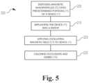
- FIG. 5is a process flow diagram of a method of preparing, inserting and in-situ cleaning an implantable device.
- the present novel technologyrelates to methods and devices by which the likelihood of formation of cellular occlusion at the site of central venous access devices in patients may be reduced.
- Magnetic nanoparticle induced hyperthermiahas been utilized in the treatment of cancer cells.
- Chronically implantable devicessuch as ventricular catheters and central venous access devices, tend to have high failure rates due to mechanical cellular occlusion of the lumen and/or inlet pores.
- chronically implantable catheters and like devicesare coated or surface-infused with superparamagnetic nanoparticles. Once implanted in a subject, the nanoparticles may be energized to induce localized hyperthermia in and around the implanted devices to reduce and/or remove cellular obstructions, and thus prolong device lifetime.
- the superparamagnetic nanoparticlesare typically magnetite (Fe 3 O 4 ), maghemite ( ⁇ -Fe 2 O 3 ), or the like and are typically provided from 10 to 100 nanometers in diameter, although the nanoparticles may be smaller than 10 nm or larger than 100 nm as desired.
- the temperature of the superparamagnetic nanoparticlesmay be increased by applying an alternating magnetic field, typically characterized by a frequency between about 0.1 and about 2 MHz, more typically about 1.2 MHz.
- the magnetic field strengthis typically between about 3 and about 40 kA/m, although other weaker or stronger field strengths may be elected.
- chronically implantable catheterssuch as ones used for hydrocephalous and central venous access, typically experience high failure rate due to cellular and thrombotic occlusions. Often, the failed devices need to be replaced to prevent the more serious side effects of hydrocephalus and catheter related thrombosis.
- the present novel technologyrelates to a system 5 for reducing clogging of catheters and like implantable devices 10 .
- the system 5operates by coating or infusing catheters, cannulas and like implantable devices 10 to define a layer or coating 20 containing magnetic nanoparticles 30 , typically homogeneously distributed throughout, the implantable devices 10 may be locally superheated through interaction of an applied oscillating magnetic field with the magnetic nanoparticles 30 sufficiently to energize and heat the device 10 to remove or reduce the formation of cellular occlusions that interfere with the proper operation of these devices 10 .
- a cannula 10is typically defined by an elongated tube portion 11 having an inner surface 12 and an oppositely disposed outer surface 13 .
- the device 10typically has a first end 14 fluidically connectable to a fluid source 16 outside the patient and a second, oppositely disposed end 17 for fluidically communicating with the patient.
- a self-clearing catheter 10includes at least one surface portion 15 coated or infused 20 with magnetic nanoparticles 30 .
- the coated or infused surface portions 15are typically positioned at or near the parts of the device 10 prone to occlusion by a build-up of cellular debris, such as openings, pores, ports, bends, junctions, or the like.
- the nanoparticles 30may be energized by application of an oscillating magnetic field to induce localized hyperthermia at the site of the occlusion.
- a method 100 of removing or reducing the formation of cellular occlusion 105 associated with a catheter 10 implanted in a patientincludes applying no a magnetic field 120 to the catheter 10 such that magnetic nanoparticles 30 on a surface 15 of the catheter 10 may be energized 130 to induce 135 localized hyperthermia 140 in and/or around predetermined portions 15 of the catheter 10 .
- Such localized hyperthermia 140reduces or removes 150 occlusions and/or built-up masses of cellular and like debris 105 .
- the nanoparticles 30may be energized 130 to induce localized heat (hyperthermia) 140 and thereby remove an organic occlusion 105 and/or reduce or retard the formation of the same 105 , resulting in the reduction of the need for revisional surgery or replacement of chronically implanted devices 10 .
- the magnetic nanoparticles 30may be energized in situ and are thus activated non-invasively.
- one method 200 of removing, or reducing the formation of, cellular occlusions 105 associated with a catheter 10 implanted in a patientincludes disposing 205 a plurality of magnetic nanoparticles 30 on those portions or locations 15 of a catheter 10 predetermined to be at risk of clogging from accretions of cellular material 105 .
- an oscillating magnetic field 215 of predetermined strength and frequencyis applied 220 to the catheter 10 .
- the applied magnetic field 215energizes 130 the magnetic nanoparticles 30 such that they generate heat 140 , and the catheter 10 is heated to a high enough temperature to calcine 225 the cellular material 105 sufficiently to reduce or eliminate the clogging mass 105 .
- the magnetic nanoparticles 30may be infused into the catheter body 10 so as to be unitary with the surface of the catheter 10 to define an infusion layer 20 , thus yielding a composite material, may be applied to an already formed catheter 10 as a coating 20 , or a combination of both.
- the coating 20may be mixed in any biocompatible silicone dispersions, polyurethane, polyethylene, polyimide solution or the like which is applied, such as by dip coating, spray coating, or the like, and is typically then cured following coating.
- the concentration of the nanoparticles 30typically ranges from 0.5-200 mg/ml, although lower or higher concentrations may be chosen as desired.
- the coating thicknesstypically ranges from 0.1-20 microns, but may be thinner or thicker.
- the magnetic nanoparticles 30are typically disposed likely to clog portions 15 of the catheter or cannula 10 , such as around an opening in the catheter defining, when placed, a patient interface.
- the magnetic nanoparticles 30may be distributed in or on the cannula in a distribution pattern and/or concentration sufficient to define a maximum temperature to which an implanted cannula 30 may be heated by an oscillating magnetic field of a given strength and frequency, typically sufficient enough to calcine away clogs or obstructing masses, but insufficient to severely or permanently damage surrounding tissue.
- Chronically implantable devices 10include central venous access devices, hydrocephalus shunt system, implantable glucose sensors, biosensors, and like devices that may suffer from functional degradation due to biofouling be coated 20 according to the present novel technology to yield systems 10 that can be energized to combat biofouling.
- the coating matrixis typically applied via spray or dip coating techniques to yield a thin external membrane or layer 20 with the nanoparticles 30 suspended therein.
- the inner lumen of the cathetersmay also be coated using low viscosity dip solution.
- the nanoparticles 30are typically mixed homogeneously to provide uniform distribution of specific nanoparticle concentration to achieve predetermined temperature for biofouling removal, although nonhomogeneous distributions are contemplated to yield predetermined temperature gradients when energized.
- nanoparticles or microparticles 30infused into the implant body (typically mad of a polymer composition), which eliminates the need for coating process.
- specific infusion depthmay be better controlled and, typically, the superparamagnetic particles are positioned near the surface, more typically within 0.1 to 20 microns.
Landscapes
- Health & Medical Sciences (AREA)
- Life Sciences & Earth Sciences (AREA)
- Animal Behavior & Ethology (AREA)
- General Health & Medical Sciences (AREA)
- Public Health (AREA)
- Veterinary Medicine (AREA)
- Epidemiology (AREA)
- Biophysics (AREA)
- Pulmonology (AREA)
- Engineering & Computer Science (AREA)
- Anesthesiology (AREA)
- Biomedical Technology (AREA)
- Heart & Thoracic Surgery (AREA)
- Hematology (AREA)
- Urology & Nephrology (AREA)
- Media Introduction/Drainage Providing Device (AREA)
- Materials For Medical Uses (AREA)
- Surgical Instruments (AREA)
Abstract
Description
Claims (15)
Priority Applications (1)
| Application Number | Priority Date | Filing Date | Title |
|---|---|---|---|
| US18/459,479US12303650B2 (en) | 2015-02-27 | 2023-09-01 | Self-clearing catheters and methods of use thereof |
Applications Claiming Priority (4)
| Application Number | Priority Date | Filing Date | Title |
|---|---|---|---|
| US201562121920P | 2015-02-27 | 2015-02-27 | |
| US15/054,398US10729879B2 (en) | 2015-02-27 | 2016-02-26 | Self-clearing catheters and methods of use thereof |
| US16/983,108US11752296B2 (en) | 2015-02-27 | 2020-08-03 | Self-clearing catheters and methods of use thereof |
| US18/459,479US12303650B2 (en) | 2015-02-27 | 2023-09-01 | Self-clearing catheters and methods of use thereof |
Related Parent Applications (1)
| Application Number | Title | Priority Date | Filing Date |
|---|---|---|---|
| US16/983,108DivisionUS11752296B2 (en) | 2015-02-27 | 2020-08-03 | Self-clearing catheters and methods of use thereof |
Publications (2)
| Publication Number | Publication Date |
|---|---|
| US20230405265A1 US20230405265A1 (en) | 2023-12-21 |
| US12303650B2true US12303650B2 (en) | 2025-05-20 |
Family
ID=56798602
Family Applications (3)
| Application Number | Title | Priority Date | Filing Date |
|---|---|---|---|
| US15/054,398ActiveUS10729879B2 (en) | 2015-02-27 | 2016-02-26 | Self-clearing catheters and methods of use thereof |
| US16/983,108Active2037-02-09US11752296B2 (en) | 2015-02-27 | 2020-08-03 | Self-clearing catheters and methods of use thereof |
| US18/459,479ActiveUS12303650B2 (en) | 2015-02-27 | 2023-09-01 | Self-clearing catheters and methods of use thereof |
Family Applications Before (2)
| Application Number | Title | Priority Date | Filing Date |
|---|---|---|---|
| US15/054,398ActiveUS10729879B2 (en) | 2015-02-27 | 2016-02-26 | Self-clearing catheters and methods of use thereof |
| US16/983,108Active2037-02-09US11752296B2 (en) | 2015-02-27 | 2020-08-03 | Self-clearing catheters and methods of use thereof |
Country Status (1)
| Country | Link |
|---|---|
| US (3) | US10729879B2 (en) |
Families Citing this family (2)
| Publication number | Priority date | Publication date | Assignee | Title |
|---|---|---|---|---|
| US10729879B2 (en)* | 2015-02-27 | 2020-08-04 | Purdue Research Foundation | Self-clearing catheters and methods of use thereof |
| WO2025106234A1 (en)* | 2023-11-15 | 2025-05-22 | Bard Access Systems, Inc. | Therapeutic systems for medical treatment with magnetoresponsive materials or structures |
Citations (11)
| Publication number | Priority date | Publication date | Assignee | Title |
|---|---|---|---|---|
| US5614652A (en)* | 1991-01-07 | 1997-03-25 | Syngenix Limited | Particulates |
| US5817017A (en)* | 1994-04-12 | 1998-10-06 | Pharmacyclics, Inc. | Medical devices and materials having enhanced magnetic images visibility |
| US6560477B1 (en) | 2000-03-17 | 2003-05-06 | The Regents Of The University Of California | Joint imaging system utilizing magnetic resonance imaging and associated methods |
| US20040265233A1 (en) | 2001-10-31 | 2004-12-30 | Susanne Holzer | Composite particle containing superparamagnetic iron oxide |
| US20090022785A1 (en) | 2005-05-03 | 2009-01-22 | Veterinarmedizinische Universitat Wien | Permeable Capsules |
| US20090081122A1 (en) | 2005-05-23 | 2009-03-26 | Universite De Geneve | Injectable superparamagnetic nanoparticles for treatment by hyperthermia and use for forming an hyperthermic implant |
| US20090179171A1 (en) | 2004-07-19 | 2009-07-16 | The Regents Of The University Of California | Control of materials and porous magnetic particles |
| US20120323318A1 (en) | 2010-03-03 | 2012-12-20 | Seikh Mohammad Yusuf | Flexible magnetic membrane based actuation system and devices involving the same |
| US20140093572A1 (en)* | 2011-05-06 | 2014-04-03 | Ut-Battelle, Llc | Active materials for prevention and treatment of fouled surfaces |
| US20150336096A1 (en) | 2012-06-25 | 2015-11-26 | The General Hospital Corporation | Sorting Particles Using High Gradient Magnetic Fields |
| US10729879B2 (en)* | 2015-02-27 | 2020-08-04 | Purdue Research Foundation | Self-clearing catheters and methods of use thereof |
- 2016
- 2016-02-26USUS15/054,398patent/US10729879B2/enactiveActive
- 2020
- 2020-08-03USUS16/983,108patent/US11752296B2/enactiveActive
- 2023
- 2023-09-01USUS18/459,479patent/US12303650B2/enactiveActive
Patent Citations (12)
| Publication number | Priority date | Publication date | Assignee | Title |
|---|---|---|---|---|
| US5614652A (en)* | 1991-01-07 | 1997-03-25 | Syngenix Limited | Particulates |
| US5817017A (en)* | 1994-04-12 | 1998-10-06 | Pharmacyclics, Inc. | Medical devices and materials having enhanced magnetic images visibility |
| US6560477B1 (en) | 2000-03-17 | 2003-05-06 | The Regents Of The University Of California | Joint imaging system utilizing magnetic resonance imaging and associated methods |
| US20040265233A1 (en) | 2001-10-31 | 2004-12-30 | Susanne Holzer | Composite particle containing superparamagnetic iron oxide |
| US20090179171A1 (en) | 2004-07-19 | 2009-07-16 | The Regents Of The University Of California | Control of materials and porous magnetic particles |
| US20090022785A1 (en) | 2005-05-03 | 2009-01-22 | Veterinarmedizinische Universitat Wien | Permeable Capsules |
| US20090081122A1 (en) | 2005-05-23 | 2009-03-26 | Universite De Geneve | Injectable superparamagnetic nanoparticles for treatment by hyperthermia and use for forming an hyperthermic implant |
| US20120323318A1 (en) | 2010-03-03 | 2012-12-20 | Seikh Mohammad Yusuf | Flexible magnetic membrane based actuation system and devices involving the same |
| US20140093572A1 (en)* | 2011-05-06 | 2014-04-03 | Ut-Battelle, Llc | Active materials for prevention and treatment of fouled surfaces |
| US20150336096A1 (en) | 2012-06-25 | 2015-11-26 | The General Hospital Corporation | Sorting Particles Using High Gradient Magnetic Fields |
| US10729879B2 (en)* | 2015-02-27 | 2020-08-04 | Purdue Research Foundation | Self-clearing catheters and methods of use thereof |
| US11752296B2 (en)* | 2015-02-27 | 2023-09-12 | Hyowon Lee | Self-clearing catheters and methods of use thereof |
Also Published As
| Publication number | Publication date |
|---|---|
| US20160250446A1 (en) | 2016-09-01 |
| US20230405265A1 (en) | 2023-12-21 |
| US10729879B2 (en) | 2020-08-04 |
| US20210038862A1 (en) | 2021-02-11 |
| US11752296B2 (en) | 2023-09-12 |
Similar Documents
| Publication | Publication Date | Title |
|---|---|---|
| US12303650B2 (en) | Self-clearing catheters and methods of use thereof | |
| JP5114482B2 (en) | Vascular access device with non-stick surface | |
| CN105722545B (en) | Treatment catheter including therapeutic energy delivery | |
| JP2019088870A (en) | Method and apparatus for delivering a drug to a target location | |
| US20130218068A1 (en) | Therapeutics reservoir | |
| EP3490653B1 (en) | Implantable intraventricular sampling and infusion access device | |
| US12433984B2 (en) | Multi-lumen indwelling catheter | |
| WO2012061193A3 (en) | Magnetic targeting device, system and method | |
| EP3157611B1 (en) | Over-the-needle catheter insert | |
| WO2020076596A1 (en) | Implantable dual pathway therapeutic agent delivery port | |
| US9138293B1 (en) | Intravascular treatment of lesions using magnetic nanoparticles | |
| WO2020149993A1 (en) | Infusing drug solution directly into brain fluid | |
| KR20110005769A (en) | System and method for heat treatment of body tissue | |
| WO2011150359A1 (en) | Tissue infusion apparatus and method | |
| US20230404736A1 (en) | Vibrating vascular filter with infusion capability | |
| CN105939751B (en) | Pleural fixation devices and methods | |
| Ananthakrishnan et al. | Central venous access port devices-a pictorial review of common complications from the interventional radiology perspective | |
| AU2005206767B2 (en) | Multilumen catheters and methods for their use | |
| Naidoo et al. | Convection-Enhanced Drug Delivery in the Central Nervous System | |
| Putterman | Intravenous Access | |
| WO2011106383A2 (en) | A catheter | |
| HK1184075A (en) | Magnetic targeting device, system and method |
Legal Events
| Date | Code | Title | Description |
|---|---|---|---|
| FEPP | Fee payment procedure | Free format text:ENTITY STATUS SET TO UNDISCOUNTED (ORIGINAL EVENT CODE: BIG.); ENTITY STATUS OF PATENT OWNER: SMALL ENTITY | |
| FEPP | Fee payment procedure | Free format text:ENTITY STATUS SET TO SMALL (ORIGINAL EVENT CODE: SMAL); ENTITY STATUS OF PATENT OWNER: SMALL ENTITY | |
| STPP | Information on status: patent application and granting procedure in general | Free format text:DOCKETED NEW CASE - READY FOR EXAMINATION | |
| AS | Assignment | Owner name:PURDUE RESEARCH FOUNDATION, INDIANA Free format text:ASSIGNMENT OF ASSIGNORS INTEREST;ASSIGNOR:LEE, HYOWON;REEL/FRAME:064951/0140 Effective date:20230905 | |
| STPP | Information on status: patent application and granting procedure in general | Free format text:NON FINAL ACTION MAILED | |
| STPP | Information on status: patent application and granting procedure in general | Free format text:RESPONSE TO NON-FINAL OFFICE ACTION ENTERED AND FORWARDED TO EXAMINER | |
| STPP | Information on status: patent application and granting procedure in general | Free format text:NON FINAL ACTION MAILED | |
| FEPP | Fee payment procedure | Free format text:PETITION RELATED TO MAINTENANCE FEES GRANTED (ORIGINAL EVENT CODE: PTGR); ENTITY STATUS OF PATENT OWNER: SMALL ENTITY | |
| STPP | Information on status: patent application and granting procedure in general | Free format text:RESPONSE TO NON-FINAL OFFICE ACTION ENTERED AND FORWARDED TO EXAMINER | |
| STPP | Information on status: patent application and granting procedure in general | Free format text:FINAL REJECTION MAILED | |
| STPP | Information on status: patent application and granting procedure in general | Free format text:RESPONSE AFTER FINAL ACTION FORWARDED TO EXAMINER | |
| STCF | Information on status: patent grant | Free format text:PATENTED CASE |