US12303242B2 - Optical vital signs sensor - Google Patents
Optical vital signs sensorDownload PDFInfo
- Publication number
- US12303242B2 US12303242B2US16/318,567US201716318567AUS12303242B2US 12303242 B2US12303242 B2US 12303242B2US 201716318567 AUS201716318567 AUS 201716318567AUS 12303242 B2US12303242 B2US 12303242B2
- Authority
- US
- United States
- Prior art keywords
- user
- force
- sensor
- skin
- vital signs
- Prior art date
- Legal status (The legal status is an assumption and is not a legal conclusion. Google has not performed a legal analysis and makes no representation as to the accuracy of the status listed.)
- Active, expires
Links
Images


Classifications
- A—HUMAN NECESSITIES
- A61—MEDICAL OR VETERINARY SCIENCE; HYGIENE
- A61B—DIAGNOSIS; SURGERY; IDENTIFICATION
- A61B5/00—Measuring for diagnostic purposes; Identification of persons
- A61B5/02—Detecting, measuring or recording for evaluating the cardiovascular system, e.g. pulse, heart rate, blood pressure or blood flow
- A61B5/024—Measuring pulse rate or heart rate
- A61B5/02416—Measuring pulse rate or heart rate using photoplethysmograph signals, e.g. generated by infrared radiation
- A—HUMAN NECESSITIES
- A61—MEDICAL OR VETERINARY SCIENCE; HYGIENE
- A61B—DIAGNOSIS; SURGERY; IDENTIFICATION
- A61B5/00—Measuring for diagnostic purposes; Identification of persons
- A61B5/02—Detecting, measuring or recording for evaluating the cardiovascular system, e.g. pulse, heart rate, blood pressure or blood flow
- A61B5/021—Measuring pressure in heart or blood vessels
- A61B5/022—Measuring pressure in heart or blood vessels by applying pressure to close blood vessels, e.g. against the skin; Ophthalmodynamometers
- A61B5/0225—Measuring pressure in heart or blood vessels by applying pressure to close blood vessels, e.g. against the skin; Ophthalmodynamometers the pressure being controlled by electric signals, e.g. derived from Korotkoff sounds
- A61B5/02255—Measuring pressure in heart or blood vessels by applying pressure to close blood vessels, e.g. against the skin; Ophthalmodynamometers the pressure being controlled by electric signals, e.g. derived from Korotkoff sounds the pressure being controlled by plethysmographic signals, e.g. derived from optical sensors
- A—HUMAN NECESSITIES
- A61—MEDICAL OR VETERINARY SCIENCE; HYGIENE
- A61B—DIAGNOSIS; SURGERY; IDENTIFICATION
- A61B5/00—Measuring for diagnostic purposes; Identification of persons
- A61B5/68—Arrangements of detecting, measuring or recording means, e.g. sensors, in relation to patient
- A61B5/6801—Arrangements of detecting, measuring or recording means, e.g. sensors, in relation to patient specially adapted to be attached to or worn on the body surface
- A61B5/6843—Monitoring or controlling sensor contact pressure
- A—HUMAN NECESSITIES
- A61—MEDICAL OR VETERINARY SCIENCE; HYGIENE
- A61B—DIAGNOSIS; SURGERY; IDENTIFICATION
- A61B5/00—Measuring for diagnostic purposes; Identification of persons
- A61B5/68—Arrangements of detecting, measuring or recording means, e.g. sensors, in relation to patient
- A61B5/6801—Arrangements of detecting, measuring or recording means, e.g. sensors, in relation to patient specially adapted to be attached to or worn on the body surface
- A61B5/6802—Sensor mounted on worn items
- A61B5/681—Wristwatch-type devices
- A—HUMAN NECESSITIES
- A61—MEDICAL OR VETERINARY SCIENCE; HYGIENE
- A61B—DIAGNOSIS; SURGERY; IDENTIFICATION
- A61B5/00—Measuring for diagnostic purposes; Identification of persons
- A61B5/68—Arrangements of detecting, measuring or recording means, e.g. sensors, in relation to patient
- A61B5/6801—Arrangements of detecting, measuring or recording means, e.g. sensors, in relation to patient specially adapted to be attached to or worn on the body surface
- A61B5/6813—Specially adapted to be attached to a specific body part
- A61B5/6824—Arm or wrist
Definitions
- the inventionrelates to an optical vital signs sensor for monitoring vital signs of a user.
- Heart rate sensors like optical heart rate sensorsare well known to monitor or detect vital signs like a heart rate of a user.
- a heart rate sensorcan be based on a photoplethysmograph (PPG) sensor and can be used to acquire a volumetric organ measurement.
- PPGphotoplethysmograph
- the PPG sensorscomprise a light source like a light emitting diode (LED) which is emitting light into the skin of a user. The emitted light is scattered in the skin and is at least partially absorbed by the blood. Part of the light exits the skin and can be captured by a photo detector.
- LEDlight emitting diode
- the amount of light that is captured by the photo detectorcan be an indication of the blood volume inside the skin of a user.
- a PPG sensorcan thus monitor the perfusion of blood in the dermis and subcutaneous tissue of the skin through an absorption measurement at a specific wave length. If the blood volume is changed due to the pulsating heart, the scattered light coming back from the skin of the user is also changing. Therefore, by monitoring the detected light signal by means of the photo detector, a pulse of a user in his skin and thus the heart rate can be determined. Furthermore, compounds of the blood like oxygenated or de-oxygenated hemoglobin as well as oxygen saturation can be determined.
- the PPG sensorcan be implemented for example in a smart watch and can be placed in direct contact with the skin of the user. If the PPG sensor is, however, not anymore in direct contact with the skin of the user, e.g. if a loss of skin contact has occurred, the output of the photo detector cannot be used to detect vital signs of a user.
- Vital signs of a usercan be the heart rate, the respiration rate, the core temperature and the blood pressure of the user.
- WO 2016/040263 A1discloses a wrist worn device for determining a pressure of blood of a user.
- An accelerometeris provided to detect when a blood pressure pulse is propagated.
- a PPG sensor or a pulse pressure sensordetects the arrival of the blood pressure at the user's wrist.
- the output signal of the accelerometer and the PPG sensorare processed to calculate a pulse transit time and to generate a pulse pressure value based on the pulse transient time.
- US 2007/0167844 A1discloses an optical vital signs sensor with a PPG sensor which is used to determine a blood pressure.
- WO 2011/082341 A1discloses an optical vital signs sensor with a PPG sensor, wherein the output of the PPG sensor is used to determine a blood pressure.
- US 2012/0215118 A1discloses a cuff for determining a blood pressure of the user.
- the cuffalso comprises a PPG sensor.
- US 2011/0208069 A1discloses a blood pressure information measuring device which includes a PPG sensor.
- US 2007/0055163 A1discloses a wearable blood pressure sensor which also comprises a PPG sensor.
- JP 2006/239114 A1discloses a blood pressure monitor having a PPG sensor.
- a (wrist worn) optical vital signs sensoris provided to measure or determine vital signs of a user.
- the optical vital signs sensoris a photoplethysmographic sensor (PPG).
- a light sourceis configured to generate light which is directed towards a skin of the user.
- the sensoralso comprises a photo detector unit configured to detect light which is indicative of a reflection of light emitted in or from the skin of the user.
- the PPC sensorcomprises a contact surface configured to be placed against a skin of a user. The light from the light source is directed towards the skin of the user via the contact surface.
- the optical vital signs sensorfurther comprises a force transducer or force measuring unit to measure a force applied via the PPG sensor to the skin of the user.
- the senorcomprises a processing unit to extract information regarding a blood volume pulse from an output signal of the PPG sensor and to map the extracted information to a blood pressure value at a specific force applied to the PPG sensor.
- a processing unitto extract information regarding a blood volume pulse from an output signal of the PPG sensor and to map the extracted information to a blood pressure value at a specific force applied to the PPG sensor.
- the force at which the PPG sensor is pressed against the skin of the useris induced by the user himself.
- the wrist worn optical vital signs sensorcomprises a force actuator to apply a force to the skin of the user via the PPG sensor in order to start the measuring process to estimate the blood pressure of a user.
- the wrist worn optical vital signs sensorcomprises a wrist band with a cavity in which a distensible membrane is arranged.
- the membranecan be inflated or deflated by means of an air pump unit in order to apply a force to the PPG sensor to press the PPG sensor against the skin of the user.
- the force transduceris coupled to the PPG sensor in order to detect a force at which the PPG sensor is pressed against a skin of the user.
- the force applied to the skin of a useris >15 N.
- the inventionalso relates to a method of measuring or determining vital signs of a user with a wrist worn optical vital signs sensor.
- the optical vital signs sensoris a PPG sensor having a contact surface, at least one light source for generating light which is directed towards the skin of the user and at least one photo detector to detect light which is indicative of a reflection of light emitted in or from the skin of the user.
- a forceis applied to the PPG sensor when the PPG sensor is pressed against a skin of the user.
- Light from the at least one light sourceis emitted towards the skin of the user and the reflective light is detected.
- the force at which the PPG sensor is pressed against the skin of the useris measured.
- Blood volume pulse informationis extracted from an output signal of the PPG sensor and the extracted blood volume pulse information is mapped to a blood pressure value at a specific force applied to the PPG sensor.
- a blood pressureis measured with an external device like a typical blood pressure cuff and the mapping of the blood volume pulse information to a blood pressure value is calibrated based on the blood pressure as measured by the external device.
- an external devicelike a typical blood pressure cuff
- the mapping of the blood volume pulse information to a blood pressure valueis calibrated based on the blood pressure as measured by the external device.
- the force transducer or the force measuring unitcan detect or measure the force directly e.g. by means of a force sensor. Alternatively, the force can be determined indirectly.
- the blood pressure valuecorresponds to the Mean Arterial Pressure MAP.
- the force applied to the skin of the useris only applied by the PPG sensor and its contact surface.
- a computer program productcomprising a computer readable memory storing computer program code means for causing the optical vital signs to carry out the steps of measuring or determining vital signs of a user as described above is provided.
- the vital signs sensorcomprises a LED based PPG sensor.
- the LED lightpenetrates the skin of the user, is reflected and some of it can reach a photo detector.
- the output of the photo detectorcan be used to monitor a blood volume fraction and blood compounds like oxygenated and de-oxygenated hemoglobin.
- the amount of absorption or reflectance of the light from the LED light sourcecan be used to determine the heart rate as well as the blood volume fraction or blood compounds.
- the heart raterelates to the blood volume fraction.
- the PPG sensor according to the inventionis therefore an optical sensor allowing a non-invasive measurement of vital signs of a user.
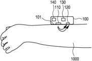
- FIG. 1shows a schematic representation of a vital signs sensor according to the invention
- FIG. 2shows a graph indicating blood pressure in several vessels of a user
- FIG. 3shows a graph indicating a correlation between a pulsatile AC component of the output of the photo detector and a mean arterial pressure as a function of an applied force
- FIG. 4shows a scatter plot between the mean arterial pressure and the AC component of the output signal of the photo detector
- FIG. 5shows a schematic cross section of an optical vital signs sensor according to a first embodiment of the invention
- FIG. 6shows a schematic representation of the optical vital signs sensor with a wrist band worn at the wrist of the user
- FIG. 7shows a schematic cross section of an optical vital signs sensor according to a second embodiment
- FIG. 8shows a schematic representation of the optical vital signs sensor worn at the wrist of the user.
- FIG. 1shows a basic representation of an operational principle of an optical vital signs sensor.
- the optical vital signs sensore.g. a heart rate sensor 100
- the contact surface 101can be (directly) placed onto the skin 1000 of the user.
- the heart rate sensor 100comprises at least one light source 110 and at least one photo detector 120 .
- the light source 110emits light via the contact surface 101 onto or in the skin 1000 of a user. Some of the light is reflected and the reflected light can be detected by the photo detector 120 . Some light can be transmitted through tissue of the user and be detected by the photo detector 120 . Based on the reflected light, vital signs of a user like a heart rate can be determined.
- pressureis applied to small vessels within the skin organ (skin arterioles).
- the optical vital signs sensor 100furthermore comprises a force transducer 130 which is able to measure the force applied to the skin 1000 of the user via the contact surface 101 .
- the force transducer 130can measure the force with which the sensor is pressed against the skin of the user.
- the optical vital signs sensor 100furthermore comprises a processing unit 140 which is used to estimate a blood pressure of a user.
- the vital signs sensor 100can be implemented as a PPG sensor or may comprise a PPG sensor.
- the output signal of the PPG sensorgives an indication on the blood movement in vessels of a user.
- the quality of the output signal of the PPG sensorcan depend on the blood flow rate, skin morphology and skin temperature.
- optical losses in the PPG sensormay also have an influence on the quality of the output signal of the PPG sensor.
- the optical efficiency of the PPG sensorcan depend on reflection losses when light penetrates from one media into another. Furthermore, scattering of light at the surface of the skin of the user may also have an influence on the optical efficiency of the PPG sensor.
- the PPG sensor or optical vital signs sensor according to an aspect of the inventioncan be implemented as a device that requires a contact with the skin of the user such as a wrist worn device (like a watch or smart watch).
- FIG. 2shows a graph indicating blood pressure P in several vessels of a user.
- the graphthus depicts the pressure P (mmHg) in the systematic SYS and the pulmonary PUL phase.
- These vesselsinclude the aorta A, large arteries LA, small arteries SA, arterioles AR, capillaries C, venules V, small veins SV, large veins LV, vena cava VC and pulmonary veins PV.
- the pressure within the arteriolesfor example is also regulated or influenced by the pressure in the larger arteries. However, the value of the pressure is much lower.
- a (wrist worn) optical vital signs sensor having a PPG sensor together with a force applied to the skin of a useris used in a non-invasive way to measure or estimate the blood pressure of a user.
- a forceis applied to the skin 1000 of the user via a contact surface 101 of the sensor 100 .
- the output of the photo detector 120is measured and based on these measurements together with an estimation of the applied force, the blood pressure is estimated by the processing unit 140 .
- the PPG sensoris used to detect variations in the blood volume pulse when no pressure is applied to the skin of the user as well as when pressure is applied to the skin of the user.
- blood pressure estimationis performed by analyzing the reaction of the blood volume pulse in the skin arterioles in response to an external force applied locally to the skin of a user.
- the force applied to the PPG sensoris first increased (ramp up) and then decreased (ramp down).
- the output signal of the PPG sensor during the ramping up of the force applied to the PPG sensoris used to determine the blood pressure of a user.
- FIG. 3shows a graph indicating a correlation between a strength of the pulsatile AC component PC of the output of the photo detector and a mean arterial pressure MAP as a function of the force applied to the sensor.
- a “negative” applied forcerelates to a higher level of pressure on the skin.
- the strength of the AC component of the output signal of the photo detectorhighly correlates with the mean arterial pressure MAP starting with force levels at 15 N or stronger.
- FIG. 4shows a scatter plot between the mean arterial pressure and the AC component AC of the output signal of the photo detector.
- FIG. 4therefore shows a correlation diagram between the mean arterial pressure and the value of the AC component of the photo detector at an applied force of 17.25 N.
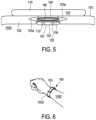
- FIG. 5shows a schematic cross section of an optical vital signs sensor according to a first embodiment of the invention.
- the vital signs sensor 100 according to the first embodimentcan be implemented as a wrist worn device like a smart watch.
- the device 100comprises a wrist band 103 , a PPG sensor 102 , a force transducer 130 , a processing unit 140 optionally, an air pump unit 150 , optionally a distensible membrane 160 and optionally a display 170 .
- a cavity 103 acan be present.
- the distensible membrane 160can be arranged inside the cavity 103 a .
- the distensible membrane 160can be arranged over the PPG sensor 102 . Between the PPG sensor 102 and the membrane 160 , the force transducer 130 is arranged.
- the deviceis provided with a force actuator or compression unit.
- the compression unit 150 , 160is implemented by the air pump unit 150 and the distensible membrane 160 .
- the compression unit 150 , 160is used to exert force on the PPG sensor 102 such that the PPG sensor 102 is pressed against the skin of a user.
- the PPG sensor 102comprises at least one light emitting diode 110 and at least one photo diode 120 .
- the function of the PPG sensor 102corresponds to the function of the PPG sensor according to FIG. 1 .
- the PPG sensor 102is used as a blood volume sensor and measures volumetric changes of the blood flow in the skin arterioles.
- the force transducer 130(arranged between the PPG sensor 102 and the compression unit 160 , 150 ) is used to measure the locally applied force on the PPG sensor 102 .
- the processing unit 140receives the output of the PPG sensor 102 and extracts features from the PPG sensor to estimate a blood pressure.
- the result of the blood pressure estimationcan be displayed on the display 170 .
- the wristband 103can be implemented as a flexible strap having two ends with a securement means to circumferentially fasten the strap around a waist of a user.
- the compression means 150 , 160By means of the compression means 150 , 160 , the PPG sensor 102 is pressed against the skin 1000 of the user.
- the PPG sensor 102is used to detect blood volume changes in particular in the skin arterioles 1001 .
- the compression means 150 , 160comprises a distensible membrane 160 which can be embedded as a distensible air bag which can be inflated or deflated by means of the air pump unit 150 .
- a forcecan be applied to the PPG sensor 102 by reducing or shrinking the inner circumference of the wristband 103 thus pressing the PPG sensor 102 against the skin of a user.
- the force transducer 130is used to detect the external force being applied to the PPG sensor 102 pressing the PPG sensor 102 against the skin of the user.
- the force transducer 130can be implemented as a strain gauge or a piezo electric sensor. According to an aspect of the invention, the detected force can be converted into an electronic signal and can be forwarded to the processor 140 .
- the PPG sensor 102can have green LEDs 110 .
- the light from the LEDsis directed into the skin surface and the photo diode 120 is used to detect the amount of reflected light.
- the amount of reflected lightvaries due to the varying amount of blood flowing through the arterioles.
- a variation in the skin-tone over timemay contain information on the blood volume.
- the output signal of the PPG sensorcan be forwarded to the processing unit 140 .
- the usershould keep his wrist and the wrist worn device at the level of his heart during the measurement period.
- the blood pressure estimation proceduremay be initiated by the user for example by pressing a button.
- the compression unit 150 , 160is activated in order to apply pressure on the PPG sensor 102 thereby pressing the PPG sensor into the skin of the user.
- the PPG sensor 102will then detect blood volume variations of the blood in the skin arterioles.
- the force applied to the skin of the usercan linearly increase from 0 N to a predefined maximum value.
- the output of the PPG sensor 102 as well as the output of the force transducer 130are forwarded to the processing unit 140 .
- the processing unit 140may comprise a unit for assessing the quality of the output of the sensor.
- the processing unit 140may furthermore comprise an extraction unit for deriving real time features from the PPG output signal. These features may include the pulsatile AC component. Also other features describing the morphology of the PPG output signal may apply.
- the processing unitmay also comprise a unit for selecting of which specific external force the extracted feature can be mapped to a blood pressure value by analyzing the sensor signal and its quality.
- the extracted PPG featuresmay be combined with other physiologic or subject specific properties measured by the optical vital signs sensor. Alternatively, these features can be stored in a memory of the device.
- the relationship between the external force, features extracted from the PPG sensor output signal and blood pressuremay be learned in an offline training stage.
- the calibration function which maps external force and features extracted from the PPG signal to a blood pressure estimatemay also include parameters related to physiological or subject specific properties.
- the processing unit 140estimates a blood pressure value.
- this estimated blood pressure valuecan be displayed on the display 170 . The pressure inside the membrane 160 can then be reduced.
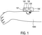
- FIG. 6shows a schematic representation of the optical vital signs sensor 100 with a wrist band 103 worn at a wrist 1002 of the user 1000 .
- FIG. 7shows a schematic cross section of an optical vital signs sensor according to a second embodiment.
- the second embodiment of the optical vital signs sensorsubstantially corresponds to the optical vital signs sensor according to a first embodiment however without a dedicated compression means 150 , 160 .
- the optical vital signs sensor 100 according to a second embodimentcomprises a wrist band 103 , a PPG sensor 102 , a force transducer 130 coupled to the PPG sensor 102 and optionally a display 170 .
- the optical vital signs sensorfurthermore comprises a processing unit 140 .
- the usermust apply the force to press the PPG sensor 100 against the skin of the user himself.
- FIG. 8shows a schematic representation of a wrist 1002 of a user together with the optical vital signs sensor during a measurement according to the second embodiment.
- the usermust apply the required force to press the PPG sensor 102 against the skin 1000 by pressing the optical vital signs sensor against his skin. The amount of pressure applied is detected by the force transducer 130 .
- the PPG sensor 102When the PPG sensor 102 is pressed against the skin of the user, the PPG sensor 102 can be activated to detect the variations in the blood volume in the skin arterioles.
- the usermay be guided by information on the display 170 through the measurement procedure.
- the processing unithas estimated the blood pressure (for example as described according to the first embodiment)
- the estimated blood pressurecan be outputted via the display.
- the second embodimentis in particular advantageous as a standard optical vital signs sensor having a PPG sensor only needs to be adapted by introducing a force transducer in order to be able to estimate the blood pressure according to the invention.
- a third embodiment of the inventionmay be based on a combination of the first and second embodiment.
- the usermust compress the device in order to supply the required force to press the PPG sensor against the skin of the user.
- the force transducer 130measures the force with which the PPG sensor is pressed against the skin of the user.
- the compression meanscan be controlled and deflected in order to reduce the force.
- an external devicelike a blood pressure cuff can be used to measure the blood pressure of the user, in particular when the PPG sensor is also determining the blood pressure of the user.
- the blood pressure of the external devicecan then be forwarded e. g. wirelessly or can be input into the PPG sensor.
- the processing unit 140can then use this blood pressure value to calibrate the mapping of the blood pressure value or the determination of the blood pressure for this specific user.
- This calibration stepcan be performed on a daily, weekly or monthly basis. With such a calibration step, the accuracy of the determined blood pressure by the PPG sensor or by the processing unit 140 can be significantly increased.
- the results of calibrationcan be forwarded to a server for further analysis to improve the algorithm in the PPG sensor.
- a single unit or devicemay fulfil the functions of several items recited in the claims.
- a computer programmay be stored/distributed on a suitable medium such as an optical storage medium or a solid state medium, supplied together with or as a part of other hardware, but may also be distributed in other forms such as via the internet or other wired or wireless telecommunication systems.
Landscapes
- Health & Medical Sciences (AREA)
- Life Sciences & Earth Sciences (AREA)
- Cardiology (AREA)
- Biomedical Technology (AREA)
- Medical Informatics (AREA)
- Physics & Mathematics (AREA)
- Veterinary Medicine (AREA)
- Biophysics (AREA)
- Pathology (AREA)
- Engineering & Computer Science (AREA)
- Public Health (AREA)
- Heart & Thoracic Surgery (AREA)
- General Health & Medical Sciences (AREA)
- Molecular Biology (AREA)
- Surgery (AREA)
- Animal Behavior & Ethology (AREA)
- Physiology (AREA)
- Vascular Medicine (AREA)
- Ophthalmology & Optometry (AREA)
- Measuring Pulse, Heart Rate, Blood Pressure Or Blood Flow (AREA)
Abstract
Description
Claims (20)
Applications Claiming Priority (4)
| Application Number | Priority Date | Filing Date | Title |
|---|---|---|---|
| EP16181087.4 | 2016-07-25 | ||
| EP16181087 | 2016-07-25 | ||
| EP16181087 | 2016-07-25 | ||
| PCT/EP2017/068564WO2018019742A1 (en) | 2016-07-25 | 2017-07-24 | Optical vital signs sensor |
Publications (2)
| Publication Number | Publication Date |
|---|---|
| US20190282107A1 US20190282107A1 (en) | 2019-09-19 |
| US12303242B2true US12303242B2 (en) | 2025-05-20 |
Family
ID=56550129
Family Applications (1)
| Application Number | Title | Priority Date | Filing Date |
|---|---|---|---|
| US16/318,567Active2039-11-03US12303242B2 (en) | 2016-07-25 | 2017-07-24 | Optical vital signs sensor |
Country Status (4)
| Country | Link |
|---|---|
| US (1) | US12303242B2 (en) |
| EP (1) | EP3487384A1 (en) |
| CN (1) | CN109496137B (en) |
| WO (1) | WO2018019742A1 (en) |
Families Citing this family (33)
| Publication number | Priority date | Publication date | Assignee | Title |
|---|---|---|---|---|
| PL3122173T5 (en) | 2014-03-26 | 2024-08-05 | Scr Engineers Ltd | Livestock location system |
| US11071279B2 (en) | 2014-09-05 | 2021-07-27 | Intervet Inc. | Method and system for tracking health in animal populations |
| US10986817B2 (en) | 2014-09-05 | 2021-04-27 | Intervet Inc. | Method and system for tracking health in animal populations |
| US10952638B2 (en) | 2015-06-12 | 2021-03-23 | ChroniSense Medical Ltd. | System and method for monitoring respiratory rate and oxygen saturation |
| US11712190B2 (en) | 2015-06-12 | 2023-08-01 | ChroniSense Medical Ltd. | Wearable device electrocardiogram |
| CN108403093B (en)* | 2018-02-27 | 2021-12-14 | 京东方科技集团股份有限公司 | Apparatus and method for determining the location of blood vessels |
| EP3533390A1 (en) | 2018-02-28 | 2019-09-04 | Koninklijke Philips N.V. | Rehabilitation system and method |
| WO2019209712A1 (en) | 2018-04-22 | 2019-10-31 | Vence, Corp. | Livestock management system and method |
| WO2019207561A1 (en)* | 2018-04-22 | 2019-10-31 | CardiacSense Ltd. | A sensor for detecting a physiological parameter of an animal |
| EP3566641A1 (en)* | 2018-05-08 | 2019-11-13 | Koninklijke Philips N.V. | Apparatus for determining a blood pressure measurement |
| EP3566639A1 (en)* | 2018-05-08 | 2019-11-13 | Koninklijke Philips N.V. | Apparatus for determining a blood pressure measurement |
| KR102775421B1 (en)* | 2018-05-10 | 2025-03-06 | 카디악센스 엘티디. | Displacement sensor for measuring biological parameters |
| FR3086837B1 (en) | 2018-10-03 | 2021-06-18 | Allflex Europe | CLAMP FOR THE HANDLING OF AN ANIMAL IDENTIFICATION DEVICE AND / OR ANIMAL TISSUE REMOVAL INCLUDING HOLDING MEANS WITH REMOTE DRIVING MEANS |
| WO2020075174A1 (en) | 2018-10-10 | 2020-04-16 | Scr Engineers Ltd | Livestock dry off method and device |
| WO2020160589A1 (en) | 2019-02-08 | 2020-08-13 | Allflex Australia Pty Ltd | Electronic animal identification tag reader synchronisation |
| EP3921763A4 (en) | 2019-02-08 | 2022-08-31 | Allflex Australia Pty Ltd | DETERMINING THE LOCATION OF AN ANIMAL |
| US12193413B2 (en) | 2019-02-08 | 2025-01-14 | Allflex Australia Pty Ltd | Electronic animal tag reader |
| CN110123270A (en)* | 2019-04-02 | 2019-08-16 | 博脉有限公司 | Pulse condition analyser output signal modification method and system |
| AU2020335853A1 (en) | 2019-08-28 | 2022-04-14 | S.C.R. (Engineers) Limited | Devices for analysis of a fluid |
| CN112450906B (en)* | 2019-09-09 | 2025-04-11 | 马克西姆综合产品公司 | Measuring system with controlled pressure ramp |
| IL275518B (en) | 2020-06-18 | 2021-10-31 | Scr Eng Ltd | An animal tag |
| USD990062S1 (en) | 2020-06-18 | 2023-06-20 | S.C.R. (Engineers) Limited | Animal ear tag |
| USD990063S1 (en) | 2020-06-18 | 2023-06-20 | S.C.R. (Engineers) Limited | Animal ear tag |
| IL275812B (en) | 2020-07-01 | 2022-01-01 | Scr Eng Ltd | A device assignment system and method |
| EP4250912A4 (en) | 2020-11-25 | 2024-05-22 | IdentiGEN Limited | A system and method for tracing members of an animal population |
| IL280374B2 (en) | 2021-01-24 | 2023-11-01 | Scr Eng Ltd | An animal marking control system and method |
| CA206812S (en) | 2021-04-08 | 2023-04-11 | Chevillot Sas | Tag applicator for animals |
| CA206747S (en) | 2021-04-08 | 2024-12-30 | Chevillot Sas | Tag applicator for animals |
| WO2023031906A1 (en)* | 2021-08-31 | 2023-03-09 | ChroniSense Medical Ltd. | Optimizing sensor pressure in blood pressure measurements using a wearable device |
| US12402596B2 (en) | 2022-05-03 | 2025-09-02 | S.C.R. (Engineers) Limited | Milk channel and feed inlet coupled thereto, and system and method for conserving wash fluid in a washing process for cleaning a milkmeter system |
| CN114812761B (en)* | 2022-05-19 | 2024-03-26 | 环荣电子(惠州)有限公司 | External force measurement system based on optical signals and measurement method thereof |
| US20230414115A1 (en)* | 2022-06-28 | 2023-12-28 | Shenzhen GOODIX Technology Co., Ltd. | Dual-altitude-based non-invasive blood pressure monitoring |
| GB2629586A (en)* | 2023-05-03 | 2024-11-06 | Earswitch Ltd | Improvements in or relating to capturing biometric data |
Citations (15)
| Publication number | Priority date | Publication date | Assignee | Title |
|---|---|---|---|---|
| US5485838A (en) | 1992-12-07 | 1996-01-23 | Nihon Kohden Corporation | Non-invasive blood pressure measurement device |
| JP2006239114A (en) | 2005-03-03 | 2006-09-14 | Citizen Watch Co Ltd | Cuff-less electronic blood pressure monitor |
| US20070055163A1 (en)* | 2005-08-22 | 2007-03-08 | Asada Haruhiko H | Wearable blood pressure sensor and method of calibration |
| US20070167844A1 (en) | 2005-11-29 | 2007-07-19 | Asada Haruhiko H | Apparatus and method for blood pressure measurement by touch |
| US20090124912A1 (en)* | 2007-11-09 | 2009-05-14 | Western Clinical Engineering Ltd. | Tourniquet Apparatus for Measuring Limb Occlusion Pressure |
| WO2011082341A1 (en) | 2009-12-30 | 2011-07-07 | Sotera Wireless, Inc. | Body-worn system for measuring continuous non-invasive blood pressure (cnibp) |
| US20110208069A1 (en) | 2008-08-29 | 2011-08-25 | Omron Healthcare Co., Ltd. | Blood pressure information measurement device |
| US20120215118A1 (en) | 2011-02-18 | 2012-08-23 | Nellcor Puritan Bennett Llc | Pattern of cuff inflation and deflation for non-invasive blood pressure measurement |
| WO2014089665A1 (en) | 2012-12-13 | 2014-06-19 | Cnv Systems Ltd. | System for measurement of cardiovascular health |
| US20150018637A1 (en) | 2012-01-16 | 2015-01-15 | Agency For Science, Technology And Research | Method and system for optical blood pressure monitoring |
| CN104688202A (en) | 2013-12-09 | 2015-06-10 | 三星电子株式会社 | Modular sensor platform |
| US20160022220A1 (en) | 2014-07-26 | 2016-01-28 | Salutron, Inc. | Sensor system for heart rate measurement per axis of shared orientation |
| WO2016040263A1 (en) | 2014-09-08 | 2016-03-17 | Braintree Analytics Llc | Wrist worn accelerometer for pulse transit time (ptt) measurements of blood pressure |
| US20170188973A1 (en)* | 2016-01-05 | 2017-07-06 | Tosense, Inc. | Physiological monitoring system featuring floormat and wired handheld sensor |
| US20180325398A1 (en)* | 2015-11-16 | 2018-11-15 | Jerusalem College Of Technology | System and method of measurement of average blood pressure |
Family Cites Families (6)
| Publication number | Priority date | Publication date | Assignee | Title |
|---|---|---|---|---|
| US11607152B2 (en)* | 2007-06-12 | 2023-03-21 | Sotera Wireless, Inc. | Optical sensors for use in vital sign monitoring |
| US8398556B2 (en)* | 2008-06-30 | 2013-03-19 | Covidien Lp | Systems and methods for non-invasive continuous blood pressure determination |
| US8834378B2 (en)* | 2010-07-30 | 2014-09-16 | Nellcor Puritan Bennett Ireland | Systems and methods for determining respiratory effort |
| US8761853B2 (en)* | 2011-01-20 | 2014-06-24 | Nitto Denko Corporation | Devices and methods for non-invasive optical physiological measurements |
| WO2016055260A1 (en)* | 2014-10-09 | 2016-04-14 | Koninklijke Philips N.V. | Optical vital signs sensor. |
| CN104257371A (en)* | 2014-10-13 | 2015-01-07 | 天津工业大学 | Research of dynamic blood pressure detection and calibration method of radial artery |
- 2017
- 2017-07-24USUS16/318,567patent/US12303242B2/enactiveActive
- 2017-07-24WOPCT/EP2017/068564patent/WO2018019742A1/ennot_activeCeased
- 2017-07-24EPEP17740408.4Apatent/EP3487384A1/ennot_activeWithdrawn
- 2017-07-24CNCN201780046246.4Apatent/CN109496137B/enactiveActive
Patent Citations (15)
| Publication number | Priority date | Publication date | Assignee | Title |
|---|---|---|---|---|
| US5485838A (en) | 1992-12-07 | 1996-01-23 | Nihon Kohden Corporation | Non-invasive blood pressure measurement device |
| JP2006239114A (en) | 2005-03-03 | 2006-09-14 | Citizen Watch Co Ltd | Cuff-less electronic blood pressure monitor |
| US20070055163A1 (en)* | 2005-08-22 | 2007-03-08 | Asada Haruhiko H | Wearable blood pressure sensor and method of calibration |
| US20070167844A1 (en) | 2005-11-29 | 2007-07-19 | Asada Haruhiko H | Apparatus and method for blood pressure measurement by touch |
| US20090124912A1 (en)* | 2007-11-09 | 2009-05-14 | Western Clinical Engineering Ltd. | Tourniquet Apparatus for Measuring Limb Occlusion Pressure |
| US20110208069A1 (en) | 2008-08-29 | 2011-08-25 | Omron Healthcare Co., Ltd. | Blood pressure information measurement device |
| WO2011082341A1 (en) | 2009-12-30 | 2011-07-07 | Sotera Wireless, Inc. | Body-worn system for measuring continuous non-invasive blood pressure (cnibp) |
| US20120215118A1 (en) | 2011-02-18 | 2012-08-23 | Nellcor Puritan Bennett Llc | Pattern of cuff inflation and deflation for non-invasive blood pressure measurement |
| US20150018637A1 (en) | 2012-01-16 | 2015-01-15 | Agency For Science, Technology And Research | Method and system for optical blood pressure monitoring |
| WO2014089665A1 (en) | 2012-12-13 | 2014-06-19 | Cnv Systems Ltd. | System for measurement of cardiovascular health |
| CN104688202A (en) | 2013-12-09 | 2015-06-10 | 三星电子株式会社 | Modular sensor platform |
| US20160022220A1 (en) | 2014-07-26 | 2016-01-28 | Salutron, Inc. | Sensor system for heart rate measurement per axis of shared orientation |
| WO2016040263A1 (en) | 2014-09-08 | 2016-03-17 | Braintree Analytics Llc | Wrist worn accelerometer for pulse transit time (ptt) measurements of blood pressure |
| US20180325398A1 (en)* | 2015-11-16 | 2018-11-15 | Jerusalem College Of Technology | System and method of measurement of average blood pressure |
| US20170188973A1 (en)* | 2016-01-05 | 2017-07-06 | Tosense, Inc. | Physiological monitoring system featuring floormat and wired handheld sensor |
Non-Patent Citations (6)
| Title |
|---|
| "Vital signs monitoring market—Landscape analysis of blood pressure monitoring devices, pulse oximeters and temperature monitoring devices", Markets and Markets, Forecast up to 2018, 2013. |
| Alpert, B. et al., "Oscillometric blood pressure: a review for clinicians", Journal of the American Society of Hypertension, 2014. |
| Elgendi, M., "On the Analysis of Fingertip Photoplethysmogram Signals", Current Cardiology Reviews, 2012. |
| McGhee, B et al., "Monitoring Arterial Blood Pressure: What You May Not Know", Critical Care Nurse, 2002. |
| Monte-Moreno, E., "Non-invasive estimate of blood glucose and blood pressure from a photoplethysmograph by means of machine learning techniques", Artificial Intelligence in Medicine, 2011. |
| Yilmaz, T. et al., "Detecting Vital Signs with Wearable Wireless Sensors", Sensors, 2010, London. |
Also Published As
| Publication number | Publication date |
|---|---|
| WO2018019742A1 (en) | 2018-02-01 |
| CN109496137B (en) | 2023-03-21 |
| US20190282107A1 (en) | 2019-09-19 |
| EP3487384A1 (en) | 2019-05-29 |
| CN109496137A (en) | 2019-03-19 |
Similar Documents
| Publication | Publication Date | Title |
|---|---|---|
| US12303242B2 (en) | Optical vital signs sensor | |
| CN112426141B (en) | Blood pressure detection device and electronic device | |
| EP3270772B1 (en) | Method and apparatus for measuring blood pressure | |
| EP3781029B1 (en) | Device, system and method for supporting detection of return of spontaneous circulation during cardiopulmonary resuscitation | |
| US10292662B2 (en) | Device and method for obtaining pulse transit time and/or pulse wave velocity information of a subject | |
| US8834378B2 (en) | Systems and methods for determining respiratory effort | |
| US20190175027A1 (en) | Biological information analysis device and system, and program | |
| US20150073239A1 (en) | Continuous cuffless blood pressure measurement using a mobile device | |
| US20180303358A1 (en) | Vital signs sensor and method of measuring vital signs of a user | |
| JP5196323B2 (en) | Blood oxygen saturation measuring device | |
| EP3048961B1 (en) | Heart rate monitor system and method of determining a warming-up status of a user | |
| JP5039123B2 (en) | Finger artery elasticity measurement program, finger artery elasticity measurement device, and finger artery elasticity measurement method | |
| KR20190043453A (en) | Apparatus and method for estimating blood pressure | |
| KR20210114228A (en) | Apparatus and method for estimating bio-information | |
| CN113226161A (en) | Control unit for deriving a measure of arterial compliance | |
| WO2019053276A1 (en) | Device for determining diastolic blood pressure of a subject | |
| JP7361046B2 (en) | Apparatus, method and computer program for determining blood pressure measurements | |
| Mouradian et al. | Continuous wearable health monitoring using novel PPG optical sensor and device | |
| Mouradian et al. | Noninvasive continuous mobile blood pressure monitoring using novel PPG optical sensor | |
| TWM547951U (en) | Biophysical signal detection apparatus | |
| EP4173555A1 (en) | Device, system and method for calibrating a blood pressure surrogate for use in monitoring a subject's blood pressure | |
| EP3456254A1 (en) | Device for determining diastolic blood pressure of a subject | |
| US20220280053A1 (en) | Electronic apparatus, and method | |
| EP3581104A1 (en) | Method, device and computer program product for estimating a compliance of a blood vessel in a subject |
Legal Events
| Date | Code | Title | Description |
|---|---|---|---|
| AS | Assignment | Owner name:KONINKLIJKE PHILIPS N.V., NETHERLANDS Free format text:ASSIGNMENT OF ASSIGNORS INTEREST;ASSIGNORS:GELISSEN, JOZEF HUBERTUS;HILBIG, RAINER;HILGERS, ACHIM;AND OTHERS;SIGNING DATES FROM 20180205 TO 20180207;REEL/FRAME:048087/0077 | |
| FEPP | Fee payment procedure | Free format text:ENTITY STATUS SET TO UNDISCOUNTED (ORIGINAL EVENT CODE: BIG.); ENTITY STATUS OF PATENT OWNER: LARGE ENTITY | |
| STPP | Information on status: patent application and granting procedure in general | Free format text:DOCKETED NEW CASE - READY FOR EXAMINATION | |
| STPP | Information on status: patent application and granting procedure in general | Free format text:RESPONSE TO NON-FINAL OFFICE ACTION ENTERED AND FORWARDED TO EXAMINER | |
| STPP | Information on status: patent application and granting procedure in general | Free format text:FINAL REJECTION MAILED | |
| STPP | Information on status: patent application and granting procedure in general | Free format text:RESPONSE AFTER FINAL ACTION FORWARDED TO EXAMINER | |
| STPP | Information on status: patent application and granting procedure in general | Free format text:ADVISORY ACTION MAILED | |
| STPP | Information on status: patent application and granting procedure in general | Free format text:DOCKETED NEW CASE - READY FOR EXAMINATION | |
| STPP | Information on status: patent application and granting procedure in general | Free format text:NON FINAL ACTION MAILED | |
| STPP | Information on status: patent application and granting procedure in general | Free format text:RESPONSE TO NON-FINAL OFFICE ACTION ENTERED AND FORWARDED TO EXAMINER | |
| STPP | Information on status: patent application and granting procedure in general | Free format text:FINAL REJECTION MAILED | |
| STPP | Information on status: patent application and granting procedure in general | Free format text:RESPONSE AFTER FINAL ACTION FORWARDED TO EXAMINER | |
| STPP | Information on status: patent application and granting procedure in general | Free format text:ADVISORY ACTION MAILED | |
| STCV | Information on status: appeal procedure | Free format text:NOTICE OF APPEAL FILED | |
| STCV | Information on status: appeal procedure | Free format text:APPEAL BRIEF (OR SUPPLEMENTAL BRIEF) ENTERED AND FORWARDED TO EXAMINER | |
| STCV | Information on status: appeal procedure | Free format text:EXAMINER'S ANSWER TO APPEAL BRIEF MAILED | |
| STCV | Information on status: appeal procedure | Free format text:ON APPEAL -- AWAITING DECISION BY THE BOARD OF APPEALS | |
| STCV | Information on status: appeal procedure | Free format text:BOARD OF APPEALS DECISION RENDERED | |
| STPP | Information on status: patent application and granting procedure in general | Free format text:NOTICE OF ALLOWANCE MAILED -- APPLICATION RECEIVED IN OFFICE OF PUBLICATIONS | |
| STPP | Information on status: patent application and granting procedure in general | Free format text:AWAITING TC RESP., ISSUE FEE NOT PAID | |
| STPP | Information on status: patent application and granting procedure in general | Free format text:NOTICE OF ALLOWANCE MAILED -- APPLICATION RECEIVED IN OFFICE OF PUBLICATIONS | |
| STCF | Information on status: patent grant | Free format text:PATENTED CASE |